Class II Div II Hazardous Environment Occupancy...
34
Class II Div II Hazardous Environment Occupancy Sensor Project Specifications First Edition 10/23/2012 Joint ECE (Team 166) and ME (Team 26) Senior Design ECE 4901/ME 4972 Fall 2012 Advisors Sung Yeul Park (EE), George Lykotrafitis (ME) Sponsored By: Contact: David Behnke ([email protected]) Computer Engineering Christopher Zannoni Electrical Engineering Christopher Zannoni Joanne Hitchcock Gledi Progonati Engineering Physics Russell Gee Mechanical Engineering Michael Gazda James Fisher
Transcript of Class II Div II Hazardous Environment Occupancy...
Class II Div II Hazardous Environment
Occupancy Sensor
Project Specifications
First Edition 10/23/2012
Joint ECE (Team 166) and ME (Team 26) Senior Design
ECE 4901/ME 4972
Fall 2012
Advisors
Sung Yeul Park (EE), George Lykotrafitis (ME)
Sponsored By:
Contact: David Behnke ([email protected])
Computer Engineering Christopher Zannoni
Electrical Engineering Christopher Zannoni
Joanne Hitchcock
Gledi Progonati
Engineering Physics Russell Gee
Mechanical Engineering Michael Gazda
James Fisher
Page 2 of 34
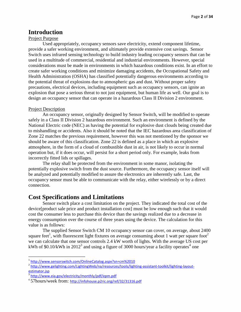
Introduction Project Purpose
Used appropriately, occupancy sensors save electricity, extend component lifetime,
provide a safer working environment, and ultimately provide extensive cost savings. Sensor
Switch uses infrared sensing technology to build industry leading occupancy sensors that can be
used in a multitude of commercial, residential and industrial environments. However, special
considerations must be made in environments in which hazardous conditions exist. In an effort to
create safer working conditions and minimize damaging accidents, the Occupational Safety and
Health Administration (OSHA) has classified potentially dangerous environments according to
the potential threat of explosions due to atmospheric gas and dust. Without proper safety
precautions, electrical devices, including equipment such as occupancy sensors, can ignite an
explosion that pose a serious threat to not just equipment, but human life as well. Our goal is to
design an occupancy sensor that can operate in a hazardous Class II Division 2 environment.
Project Description
An occupancy sensor, originally designed by Sensor Switch, will be modified to operate
safely in a Class II Division 2 hazardous environment. Such an environment is defined by the
National Electric code (NEC) as having the potential for explosive dust clouds being created due
to mishandling or accidents. Also it should be noted that the IEC hazardous area classification of
Zone 22 matches the previous requirement, however this was not mentioned by the sponsor we
should be aware of this classification. Zone 22 is defined as a place in which an explosive
atmosphere, in the form of a cloud of combustible dust in air, is not likely to occur in normal
operation but, if it does occur, will persist for a short period only. For example, leaks from
incorrectly fitted lids or spillages.
The relay shall be protected from the environment in some manor, isolating the
potentially explosive switch from the dust source. Furthermore, the occupancy sensor itself will
be analyzed and potentially modified to assure the electronics are inherently safe. Last, the
occupancy sensor must be able to communicate with the relay, either wirelessly or by a direct
connection.
Cost Specifications and Limitations Sensor switch place a cost limitation on the project. They indicated the total cost of the
device[product sale price and product installation cost] must be low enough such that it would
cost the consumer less to purchase this device than the savings realized due to a decrease in
energy consumption over the course of three years using the device. The calculation for this
value is as follows:
The supplied Sensor Switch CM 10 occupancy sensor can cover, on average, about 2400
square feet1, with fluorescent light fixtures on average consuming about 1 watt per square foot
2
we can calculate that one sensor controls 2.4 kW worth of lights. With the average US cost per
kWh of $0.10/kWh in 20123 and using a figure of 3000 hours/year a facility operates
4 one
1 http://www.sensorswitch.com/OnlineCatalog.aspx?sn=cm%2010
2 http://www.gelighting.com/LightingWeb/na/resources/tools/lighting-assistant-toolkit/lighting-layout-
estimator.jsp 3 http://www.eia.gov/electricity/monthly/pdf/epm.pdf
4 57hours/week from: http://infohouse.p2ric.org/ref/32/31316.pdf
Page 3 of 34
occupancy sensor controls $720/year worth of electricity. Storage areas or warehouses would be
a good example a division 2 area5. According to a U.S. EPA Prediction
6 a storage area is
occupied 45%-80% of the time. Using this percentage, one sensor would save $144-$396 per
year in electricity costs if the lights were on 100% of the operating time without a sensor. Using
the 3 year constraint mentioned earlier the cost of the sensor, relay and installation, cannot be
more than $432-$1188.
Regulations Related to Project that Drive Specifications: The largest part of our project specifications come from hazardous location regulations.
Below are the specifications from various hazardous location regulations that pertain to our
project
NEC 2011 Regulations:
Article 500: Hazardous (Classified) Locations, Classes I, II, III, Divisions 1
and 2
500.5 Classifications of Locations
Class II, Division 2.
A Class II, Division 2 location is a location:
Where combustible dust may be present in the air in quantities that can produce
explosive or ignitable mixtures
Where combustible dust accumulations are present but there is not enough dust to
interfere with the operation of electrical equipment, but it could interfere with
operation of equipment if there is mishandling of equipment and the dust becomes
suspended in the air.
Where combustible dust accumulates near electrical equipment it can interfere
with the safe dissipation of heat from electrical equipment, or there could be an
ignitable failure of electrical equipment.
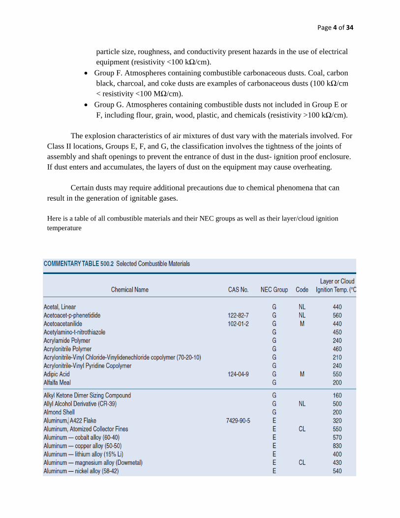
500.6 Material Groups
Class II Group Classifications
Group E. Atmospheres containing combustible metal dusts, including aluminum,
magnesium, and their commercial alloys, or other combustible dusts whose
5 Understanding Hazardous Area Sensing-Intrinsic Safety, handbook by Bob Svacina and Brad
Larson found at: http://www.parrinst.com/wp-content/uploads/downloads/2011/06/Svacina-
Larson_Understanding-Hazardous-Area-Sensing_Intrinsic-Safety.pdf 6 Although the actual report could not be found, this number is used throughout the industry. Additionally we did
find a study by a member of the EPA ENERGY STAR Buildings Program, Bill VonNeida, who referenced that this number. The report is found here: http://www.lrc.rpi.edu/resources/pdf/dorene1.pdf
Page 4 of 34
particle size, roughness, and conductivity present hazards in the use of electrical
equipment (resistivity <100 kΩ/cm).
Group F. Atmospheres containing combustible carbonaceous dusts. Coal, carbon
black, charcoal, and coke dusts are examples of carbonaceous dusts (100 kΩ/cm
< resistivity <100 MΩ/cm).
Group G. Atmospheres containing combustible dusts not included in Group E or
F, including flour, grain, wood, plastic, and chemicals (resistivity >100 kΩ/cm).
The explosion characteristics of air mixtures of dust vary with the materials involved. For
Class II locations, Groups E, F, and G, the classification involves the tightness of the joints of
assembly and shaft openings to prevent the entrance of dust in the dust- ignition proof enclosure.
If dust enters and accumulates, the layers of dust on the equipment may cause overheating.
Certain dusts may require additional precautions due to chemical phenomena that can
result in the generation of ignitable gases.
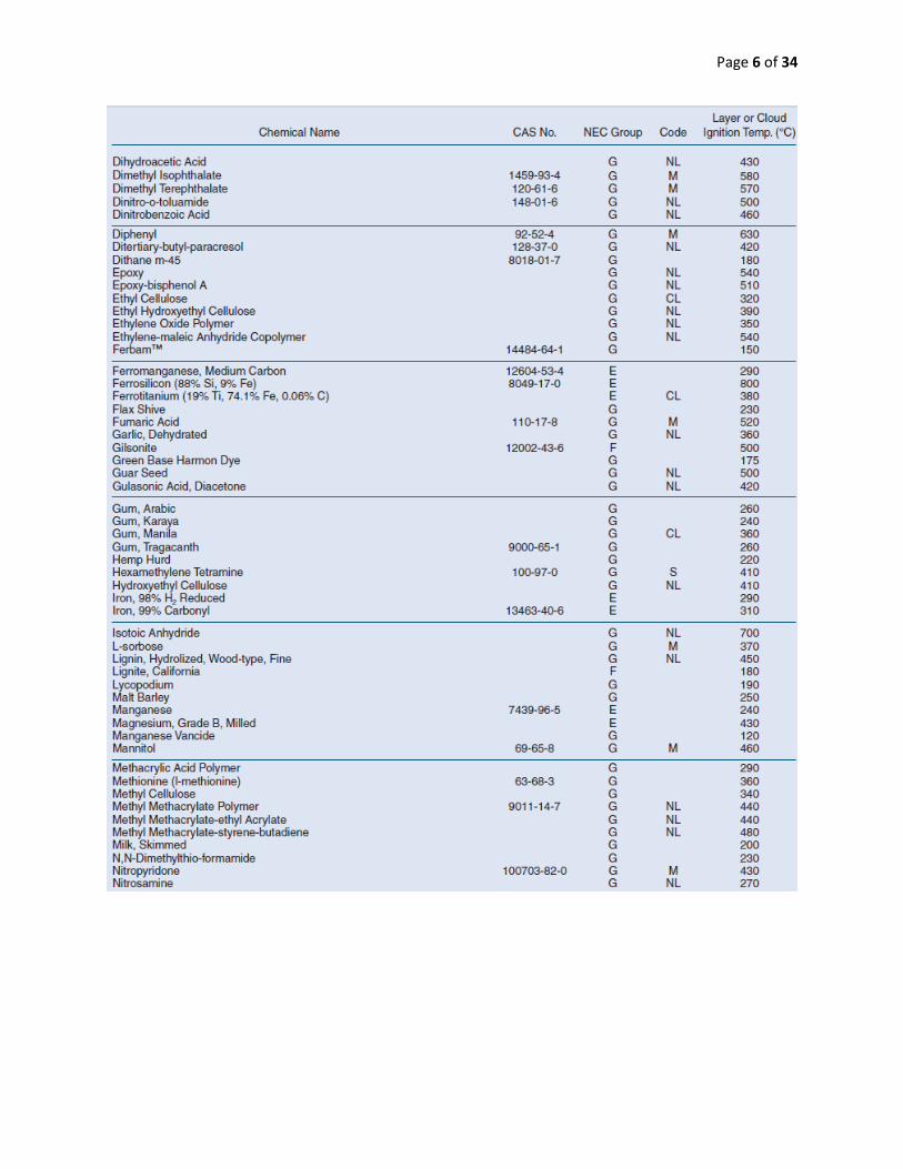
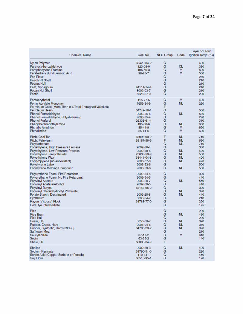
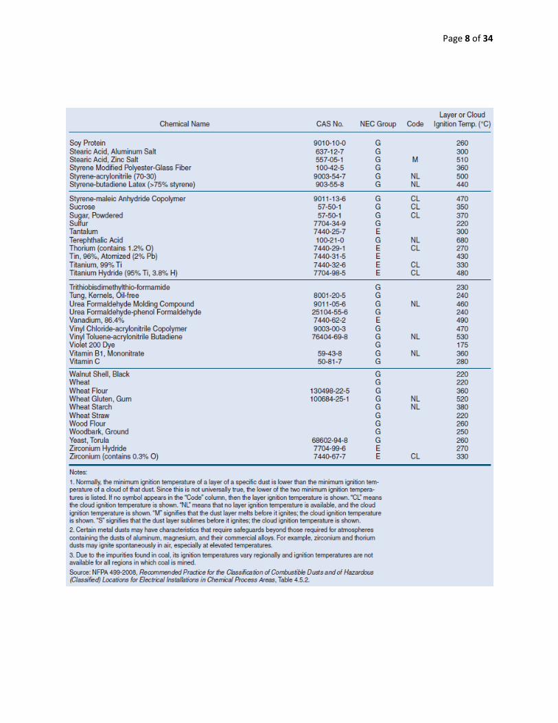
Here is a table of all combustible materials and their NEC groups as well as their layer/cloud ignition
temperature

Page 5 of 34
Page 6 of 34
Page 7 of 34
Page 8 of 34
Page 9 of 34
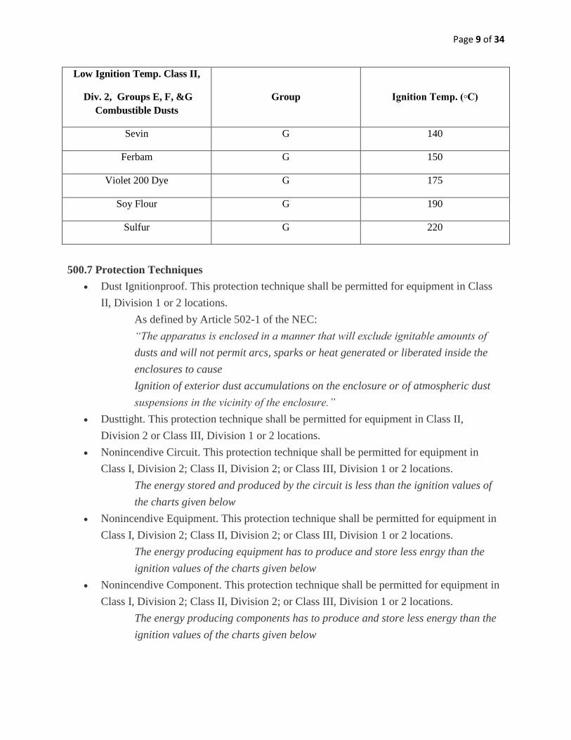
Low Ignition Temp. Class II,
Div. 2, Groups E, F, &G
Combustible Dusts
Group
Ignition Temp. (C)
Sevin G 140
Ferbam G 150
Violet 200 Dye G 175
Soy Flour G 190
Sulfur G 220
500.7 Protection Techniques
Dust Ignitionproof. This protection technique shall be permitted for equipment in Class
II, Division 1 or 2 locations.
As defined by Article 502-1 of the NEC:
“The apparatus is enclosed in a manner that will exclude ignitable amounts of
dusts and will not permit arcs, sparks or heat generated or liberated inside the
enclosures to cause
Ignition of exterior dust accumulations on the enclosure or of atmospheric dust
suspensions in the vicinity of the enclosure.”
Dusttight. This protection technique shall be permitted for equipment in Class II,
Division 2 or Class III, Division 1 or 2 locations.
Nonincendive Circuit. This protection technique shall be permitted for equipment in
Class I, Division 2; Class II, Division 2; or Class III, Division 1 or 2 locations.
The energy stored and produced by the circuit is less than the ignition values of
the charts given below
Nonincendive Equipment. This protection technique shall be permitted for equipment in
Class I, Division 2; Class II, Division 2; or Class III, Division 1 or 2 locations.
The energy producing equipment has to produce and store less enrgy than the
ignition values of the charts given below
Nonincendive Component. This protection technique shall be permitted for equipment in
Class I, Division 2; Class II, Division 2; or Class III, Division 1 or 2 locations.
The energy producing components has to produce and store less energy than the
ignition values of the charts given below
Page 10 of 34
Hermetically Sealed. This protection technique shall be permitted for equipment in Class
I, Division 2; Class II, Division 2; or Class III, Division 1 or 2 locations.
An enclosure that is sealed air tight and certified to be used in a hazardous
location
500.8 Construction and installation of equipment under hazardous locations
Suitability of equipment
o All equipment must have a listing or label with evidence from a qualified testing
laboratory or inspection agency concerned with product evaluation
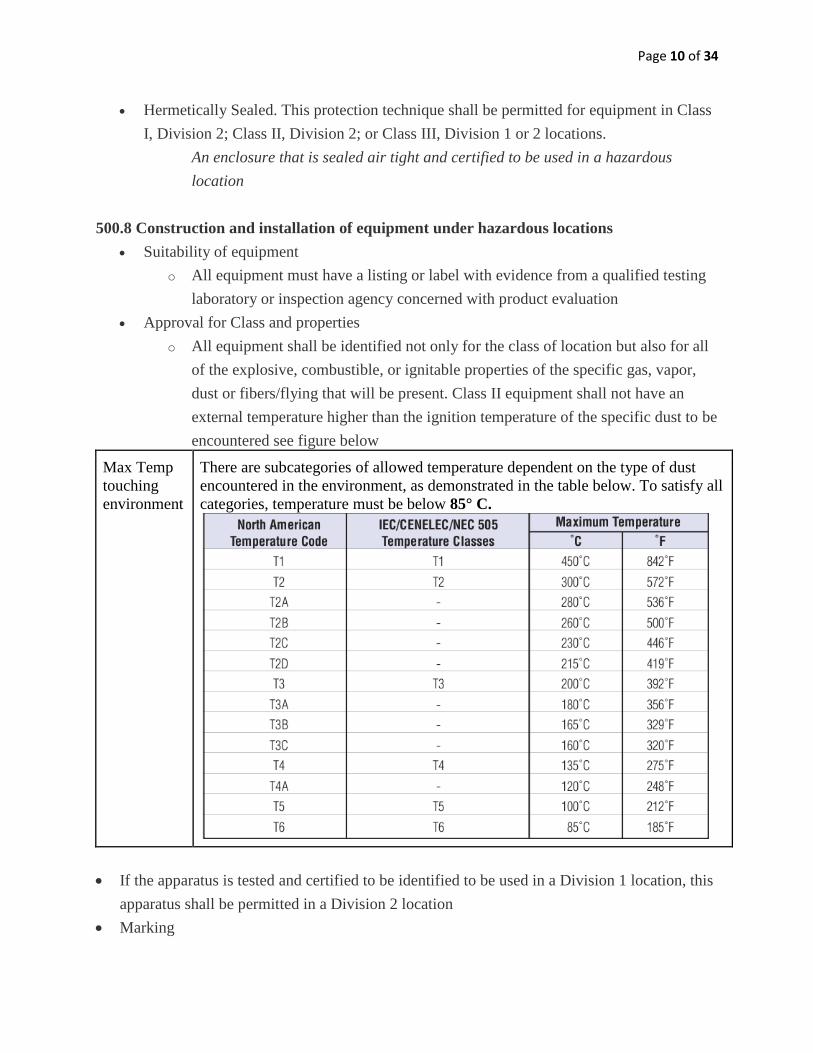
Approval for Class and properties
o All equipment shall be identified not only for the class of location but also for all
of the explosive, combustible, or ignitable properties of the specific gas, vapor,
dust or fibers/flying that will be present. Class II equipment shall not have an
external temperature higher than the ignition temperature of the specific dust to be
encountered see figure below
Max Temp
touching
environment
There are subcategories of allowed temperature dependent on the type of dust
encountered in the environment, as demonstrated in the table below. To satisfy all
categories, temperature must be below 85° C.
If the apparatus is tested and certified to be identified to be used in a Division 1 location, this
apparatus shall be permitted in a Division 2 location
Marking
Page 11 of 34
o All equipment shall be marked to show the environment for which it has been
evaluated.
Class
Division
Materials (Groups E, F, and G)
Equipment Temperature: the operating temperature and the maximum safe
operating temperature
Threading: The supply connection entry thread form shall be NPT or metric. Conduit and
fittings shall be made wrench tight to prevent sparking when fault current flows through the
conduit system, and to ensure the explosion proof integrity of the conduit system where
applicable. Equipment provided with threaded entries for field wiring connections shall be
installed in accordance with the following:
Equipment Provided with Threaded Entries for NPT Threaded Conduit or Fittings. For
equipment provided with threaded entries for NPT threaded conduit or fittings, listed conduit,
conduit fittings, or cable fittings shall be used. All NPT threaded conduit and fittings shall be
threaded with a National (American) Standard Pipe Taper (NPT) thread.
Unused Openings: All unused openings shall be closed with listed metal close-up plugs.
The plug engagement shall comply with the above.
Article 502: Class II Locations
502.5 Explosionproof Equipment
Explosion proof equipment and wiring shall not be required and shall not be acceptable in
Class II locations unless also indentified for such locations.
Note: Electrical equipment required in Class II locations is different from that required
for Class I locations. Class II equipment is designed to prevent the ignition of layers of
dust, which may cause an increase in operating temperature, which Class II equipment
does not address this concern.
Dust-ignition proof enclosures are not required to be explosion proof
502.6 Zone Equipment
Equipment listed and marked in accordance with 506.9(c) for Zone 20,21,22 locations
shall be permitted in Class II div 2 locations for the same dust atmosphere and with a
suitable temperature class.
II. Wiring
502.10 Wiring Methods
Page 12 of 34
1. Rigid metal conduit, intermediate metal conduit, electrical metallic tubing, dusttight
wireways
2. Type MC or MI cable with listed termination fittings
3. Type PLTC and Type PLTC-ER cable in accordance with the provisions of article 725,
including installation in cable tray systems. The cable shall be terminated with listed
fittings
4. Type ITC and Type ITC-ER cable as permitted in 727.4 and terminated with listed
fittings.
5. Type MC, MI, or TC cable installed in ladder, ventilated trough, or ventilated channel
cable trays in a single layer, with a space not less than the larger cable diameter between
the two adjacent cables, shall be the wiring method employed.
6. Reinforced Thermosetting resin conduit RTRC, all marked with suffice –XW and
Schedule 80 PVC conduit, shall be permitted
7. Exception Type MC cable shall be permitted to be installed without the spacing required
by 5.
Flexable Connections.
1. Dust tight flexible connectors
2. Liquidtight flexible metal conduit with listed fittings
3. Liquidtight flexible nonmetallic conduit with listed fittings
4. Interlocked armor tyoe MC cable having an overall jacket of suitable polymeric material
and provided with termination fittings listed for class II, division 1 locations
5. Flexible cord listed for extra-hard usage and terminated with listed dusttight fittings,
Where flexible cords are used they shall comply with 502.140
1. Liquidtight flexible conduit or extra-hard-usage flexible cord is permitted.
However a bonding jumper must be provided around such conduit (see 502.30),
and an additional conductor for grounding must be used in conjunction with
flexible cords.
Nonincendive field wiring: (wiring entering or leaving an enclosure where grounding or shorting
of the wiring does not ignite the atmosphere around it)
Installation:
1. In separate cables
2. In multiconductor cables where the conductors of each circuit are within a grounded
metal shield
3. In multiconductor cables or in raceways where the conductors of each circuit have
insulation with a minimum thickness of 0.25mm.
All boxes and fittings shall be dusttight
Page 13 of 34
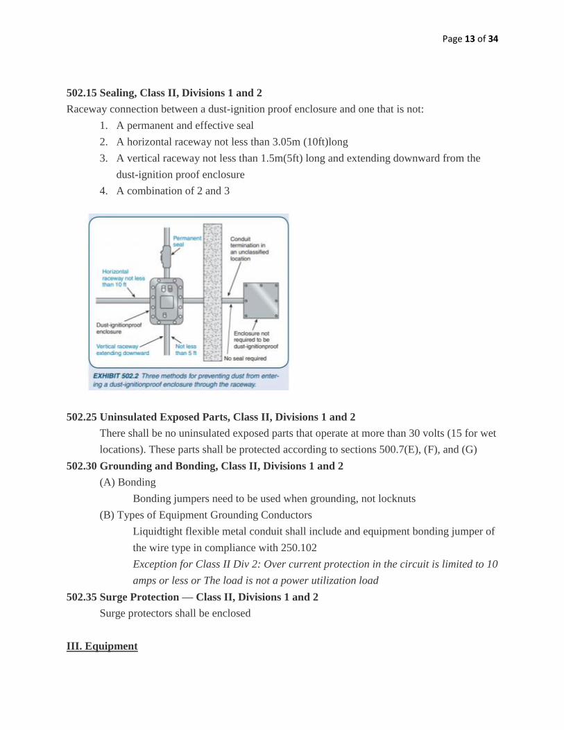
502.15 Sealing, Class II, Divisions 1 and 2
Raceway connection between a dust-ignition proof enclosure and one that is not:
1. A permanent and effective seal
2. A horizontal raceway not less than 3.05m (10ft)long
3. A vertical raceway not less than 1.5m(5ft) long and extending downward from the
dust-ignition proof enclosure
4. A combination of 2 and 3
502.25 Uninsulated Exposed Parts, Class II, Divisions 1 and 2
There shall be no uninsulated exposed parts that operate at more than 30 volts (15 for wet
locations). These parts shall be protected according to sections 500.7(E), (F), and (G)
502.30 Grounding and Bonding, Class II, Divisions 1 and 2
(A) Bonding
Bonding jumpers need to be used when grounding, not locknuts
(B) Types of Equipment Grounding Conductors
Liquidtight flexible metal conduit shall include and equipment bonding jumper of
the wire type in compliance with 250.102
Exception for Class II Div 2: Over current protection in the circuit is limited to 10
amps or less or The load is not a power utilization load
502.35 Surge Protection — Class II, Divisions 1 and 2
Surge protectors shall be enclosed
III. Equipment
Page 14 of 34
502.100 Transformers and Capacitors
Can not contain liquid that will burn. If it does then it needs to be in a vaults that comply
with 450.41-450.48
502.115 Switches, Circuit Breakers, Motor Controllers, and Fuses
(B) Class II, Division 2. In Class II, Division 2 locations, enclosures for fuses, switches,
circuit breakers, and motor controllers, including push buttons, relays, and similar
devices, shall be dusttight or otherwise identified for the location.
502.120 Control Transformers and Resistors
Switching mechanisms and coils/ windings have to be dusttight
502.140 Flexible Cords — Class II, Divisions 1 and 2
Be supported by clamps so there is no tension on the wires
Must be dusttight
502.145 Receptacles and Attachment Plugs
Of the type that provides for connection to the equipment grounding conductor of the
flexible cord and shall be designed so that connection to the supply circuit cannot be
made or broken while live parts are exposed
The following information summarizes section 504 of the National Electrical Code. The
abbreviation IS will be used to abbreviate “Intrinsically Safe”. Sections of particular
relevance to our project have been bolded.
Article 504: Intrinsically Safe Conductors
Definition: “Simple Apparatus”:
A. Passive Components (switches, junction boxes, resistors, simple semiconductors (i.e.
LEDs)
B. Sources of stored energy consisting of single components (i.e. capacitors or inductors)
C. Sources of generated energy (i.e. photocells)
Control Drawings
A. IS apparatus, associated apparatus and other equipment shall be installed in accordance
with the control drawing(s).
i) Control drawing identification is marked on apparatus
ii) Associated apparatus over 250 V has special conditions
Since IS systems are to be installed according to control drawing, this puts limitations on cables
and separation of circuits in the system. Also illustrates what is allowed to be connected to
system. Testing by third parties is based on installation with accordance with control drawing.
Surface Temperature
Surface Temp can be calculated by following equation:
Page 15 of 34
T=P0Rth+Tamb
P0 = output power
Rth = thermal resistance of simple apparatus
Tamb = ambient temperature (typically room temp, but also reference Table 500.8)
In addition, components with surface area less than 10cm2 may be classified as T5
if surface temperature does not exceed 150C.
Wiring methods suitable for unclassified locations (covered Ch7, Ch8) are permitted for IS.
Separation of IS Conductors
a) Conductors of IS circuits cannot be placed in raceways, cable tray or cable with
conductor from non-IS circuit
i) Exception: If conductors are separated by 50mm and secured or by an approved
insulating partition or grounded metal partition
ii) Exception: All IS conductors and all non-IS conductors are in grounded metal-
sheathed or metal-clad cables where fault current is capable of going to ground
iii) Exception: IS circuit in Div2 or Zone 2 shall be permitted to be installed in a
raceway, cable tray or cable along with nonincendive field wiring circuits when
installed as long as :
1. Conductors are within a grounded metal shield OR
2. Conductors of each circuit have insulation with min thickness of .25mm
b) In enclosures, conductors of IS circuits shall be secured so that any conductor that might
come loose from a terminal in unlikely to come into contact with another terminal. One
of the following methods may be used to do this:
i) Separation by at least 50mm
ii) Separation by grounded metal partition or insulated partition
iii) Metal sheathed cables
Grounding
a) IS apparatus, enclosures and raceways shall be connected to equipment grounding
conductor
b) Associated apparatus and cable shields must be grounded with accord to control drawing
c) When connection to grounding electrode is necessary, special conditions necessary (see
NEC for details)
Bonding
a) Hazardous Locations: IS apparatus shall be bonded with accordance to 250.100. 250.10
summarized as follows:
Page 16 of 34
i) Ground clamps and other fittings are approved for general use without protection if
they are in installations where they are unlikely to be damaged, or enclosed in metal,
wood or equivalent protective covering.
b) Unclassified: See NEC
Sealing
a) Conduits and cables required to be sealed by NEC shall be sealed to minimize passage of
hazardous gases, vapors, dusts. Such seals shall not be required to be explosionproof or
flameproof but shall be identified for the purpose of minimizing dust passage under
normal operating conditions and shall be accessible.
b) Exception: Seals shall not be required for enclosures that contain only IS safe apparatus,
except as required by 501.12(F)(3)
Identification
a) Terminals: IS circuits shall be identified at terminal and junction locations in a manner
intended to prevent unintentional interference with the circuits during testing and
servicing.
b) Wiring: Raceways, cable trays and other wiring methods for IS system wiring shall be
identified with the affixed label: “Intrinsic Safety Wiring” or equivalent. Must be visible
after installation and placed to be readily traced through entire length of installation.
Labels shall be appear in every section separated by enclosures, walls, partitions, floors.
Spacing between labels cannot exceed more than 7.5m. (Exception for underground
cables).
c) Color Coding: Color coding shall be permitted to identify IS conductors colored light
blue and where no other conductors colored light blue are used. (Basically if IS
conductor is colored light blue, this satisfies Identification requirement as long as there
are no other light blue conductors).
UL913, Fourth Edition, Regulations: Intrinsically Safe Apparatus7
(2) Intrinsic Safe Apparatus
(2.1.1) The energy available in the hazardous location shall not be capable of igniting the
flammable mixture specified in 8.3.1 through 8.3.5 due to arcing or hot surfaces during normal
operation.
(2.1.1.1) Normal Operation is defined as:
7 From UL913, Fourth Edition from 1988. Due to cost constraint as of 10/23/12 the most recent edition, seventh
edition from 2011, was not investigated. However the latest edition will be bought and investigated later in the project
Page 17 of 34
Circuit is at 1.5x its max energy rating
Environmental conditions within the ratings given:
Maximum rated supply voltage
Tolerances of components are at most unfavorable conditions
Adjustments are at most unfavorable
Shorting, grounding or opening of any field wires
(2.1.2.1)Circuit is under fault conditions, which include: (see article 2 for fault
definitions)
The most unfavorable single fault and any subsequent related defects and breakdowns,
with an additional test factor of 1.5 applied to energy;
The most unfavorable combination of two faults and any subsequent related defects and
breakdowns, with no additional test factor. Such test factors are to be achieved according
to the procedures outlined in 8.6 through 8.6.4.
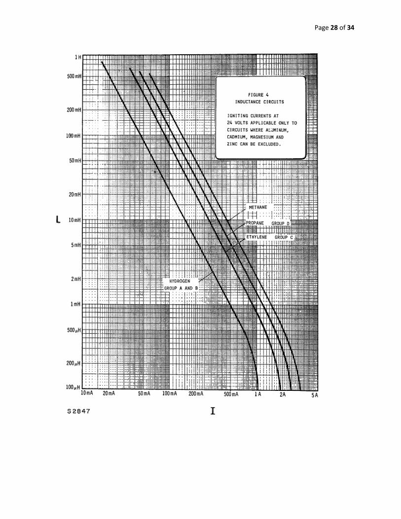
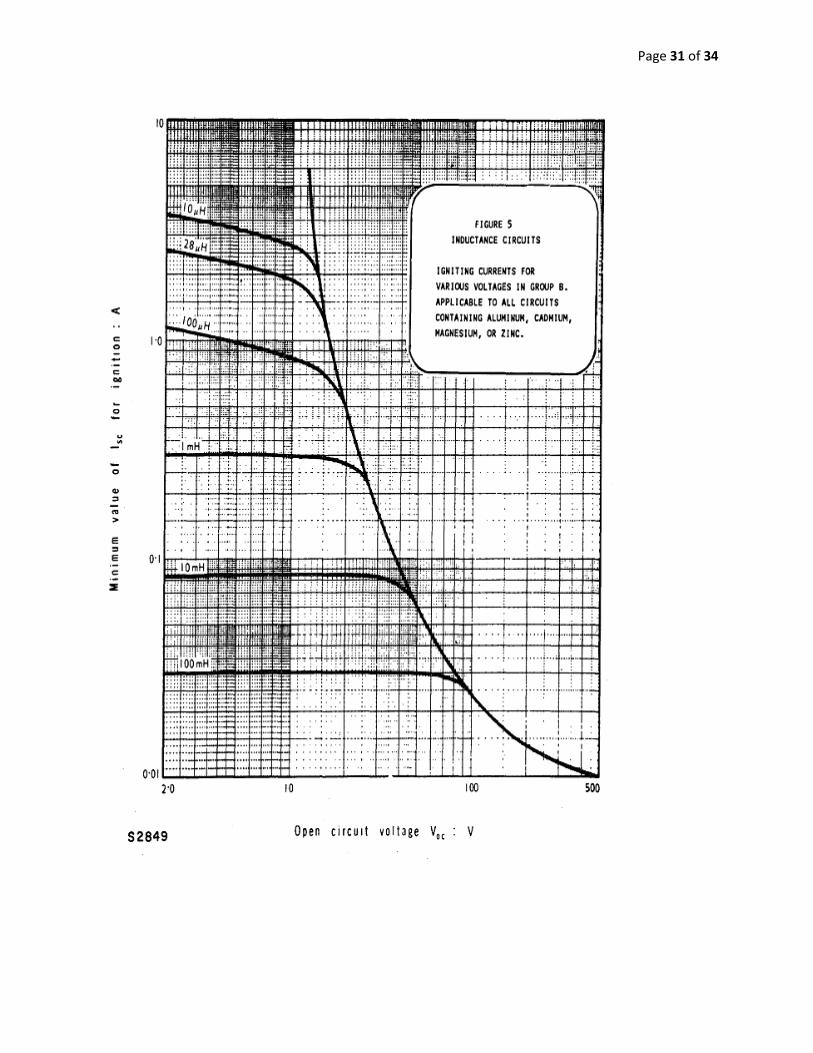
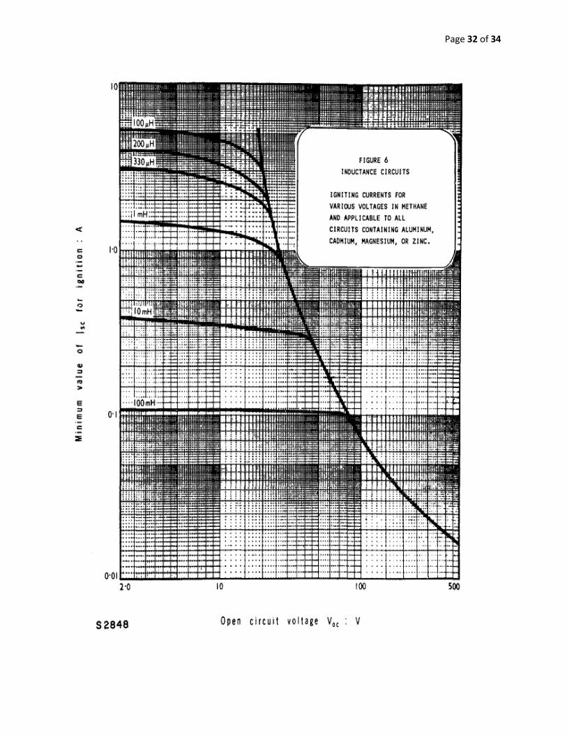
(2.2.3) The possibility of arc ignition under normal and fault conditions is to be determined by
either of the following two procedures:
Testing the circuit according to the test requirements of Section 8; or
Comparing the calculated or measured values of current, voltage, and associated
inductances and capacitances to the appropriate figures in Section 5 to establish that the
current and voltage levels are below the specified values in 5.2.1 through 5.2.2.
(2.2.4) Ignition sources are the following:
Sources of spark ignition:
Discharge of a capacitive circuit;
Interruption of an inductive circuit;
Intermittent making and breaking of a resistive circuit;
Hot wire fusing.
Sources of thermal ignition:
Heating of small gage wire strand;
Glowing of a filament;
Page 18 of 34
High surface temperature of components.
(2.4) Associated Apparatus Evaluation.
Associated apparatus is to be evaluated to determine that the output is intrinsically
safe. Associated apparatus shall comply with 2.1 through 2.2.4.
(2.4.1) The maximum output voltage is to be the highest output voltage from the following:
No faults and the most unfavorable normal operating condition.
The most unfavorable one fault condition.
The most unfavorable two fault condition.
(2.4.2) The maximum output current is to be the highest shortcircuit current obtainable under
the conditions specified in 2.4.1.
(2.4.3) The maximum allowed capacitance is determined by test or by comparison and is the
lower value obtained from the following:
The maximum capacitance that does not cause ignition at 1.22 times the maximum output
voltage if this voltage was determined with less than two faults.
The maximum capacitance that does not cause ignition at the maximum output voltage if
this voltage was determined with two faults.
(2.4.4) The maximum allowed inductance is determined by test or by comparison and is the
lower value obtained from the following:
The maximum inductance that does not cause ignition at 1.22 times the maximum output
current if this current was determined with less than two faults.
The maximum inductance that does not cause ignition at the maximum output current if
this current was determined with two faults.
(2.5) Intrinsically Safe Apparatus Inductance and Capacitance Determination. The intrinsically
safe apparatus maximum internal capacitance or inductance is to be determined considering both
normal and fault conditions by one of the following methods:
Inspection or analytical computation; or
Confirmation of the value by testing in accordance with 7.14.1 through 7.14.6, if the
apparatus manufacturer declares a maximum internal capacitance or maximum internal
inductance value; or
Derivation of the value of maximum internal capacitance or maximum internal inductance
using the procedure specified in 7.14.1 through 7.14.6.
Page 19 of 34
Faults:
Fault Definitions:
One fault is counted if all associated apparatus common to the loop are considered to be
at their maximum voltages and currents.
A fault is only counted after 2 shorts of the outputs or after 1 grounded output. If two
associated apparatus outputs are shorted and then the connection is grounded, the
grounding is a countable fault.
Current limiting resisters are not considered subject to fault if are a film type, wirewound
type, or if broken provide a larger resistance
Shunt protective components are not considered subject to fault (see section for details)
(2.6) Intrinsically Safe and Associated Apparatus
A control drawing needs to accompany the part shall contain notes to explain the
following if applicable:
Specifies the allowed apparatus on each terminal
Which apparatus terminal normally supplies power
(2.6.7)Polarity for associated apparatus
(2.6.7)How to calculate allowed capacitance and inductance values for field wiring used in the
intrinsically safe circuit
(2.7) Intrinsically Safe Apparatus Evaluation. Intrinsically safe apparatus is to be evaluated for
the possibility of arc ignition or hot surface ignition using 2.1 through 2.2.4. The associated
apparatus connected to each terminal is determined from the control drawing. The number of
faults counted when connecting various allowed combinations of the associated apparatus is
described in 2.6 through 2.6.7.
(2.7.1)The determination of temperature rise of a component in an entity evaluation is to be
made using a power source having parameters that are within the stated entity parameters at a
voltage and current that is on the relevant ignition curve and that results in maximum power
transfer.
(2.7.2)Capacitive discharge evaluation of the intrinsically safe apparatus is done using the
highest specified maximum output voltage from any set of parameters adjusted by the test
factor described in 2.1.2.1, considering current drawn from the source during discharge.
(2.7.3) Inductive discharge evaluation of the intrinsically safe apparatus is to be done using an
equivalent power source that has parameters within the stated entity parameters at a voltage
and current that lie on the relevant ignition curve. The source is to be chosen that causes
Page 20 of 34
maximum current flow in the inductor. The current is adjusted using the test factor described
in 2.1.2.1.
(3)Construction Requirements
(3.1)Creepage and Clearance Distances (see table 1)
(3.1.1)If insulators are at least 1/3 of table values then they are considered a possible fault
(3.1.2)If separation is less than 1/3 of table values then they are considered a possible
fault
(3.1.3) If more than two conductors are involved and the spacing between adjacent
conductors is less than one third the applicable value in Table 1, the sum of the individual
spacings is to be added until the total spacing equals or exceeds one third the applicable
value. Only that number of conductors is to be considered connected. A single fault
is to be counted. Within a total dimension equal to the applicable table value, only one
such group of conductors is to be considered connected.
(3.4)If components are not rigidly supported so they don’t comply with table follow
3.4.1-3.4.3 for insulating and separating these components
(3.1.5)Printed circuits distance from ground planes to other traces don’t have to comply
with table as long as they ground can carry max current at fault condition.
(3.1.6)Field wiring must be separated by 0.25in unless no hazard results from connection.
(3.1.7)Creepage under coating for PCB’s is:
1) Two layers of solder resist or varnish with min dielectric voltage rating of 200 volts per
0.025mm; or
2) A single layer of .7mm; or
3) Complies with voltage test in 7.7.3.
(3.2)Encapsulation
Can be used to separate conductors (casting compound table 1) if encapsulation is used to
reduce ignition the minimum thickness has to be
(3.3)Field wiring
Adjacent terminals between IS an non-IS must be at least 50mm(2in). Care must be taken
so that they do not come in contact with each other if dislodged.
Page 21 of 34
Plugs cannot be interchangeable as to prevent wrong connections.
(3.6)Miscellaneous Components
(3.6.1.1) Plugs shall not be interchangeable with non identical boards or components in
the same apparatus.
Exception is if IS is not affected from interchange, if it is unlikely are identified
so that it is unlikely
(3.7) Portable Apparatus Enclosures
(3.7.1)Exposed external surfaces of the external enclosure and parts shall be made of a
nonsparking material, such as plastic or brass, unless the part is protected by a recess or
a guard.
Exception: Such a surface may be of a sparking material if an investigation
indicates that percussion sparks capable of igniting a flammable atmosphere are
unlikely.
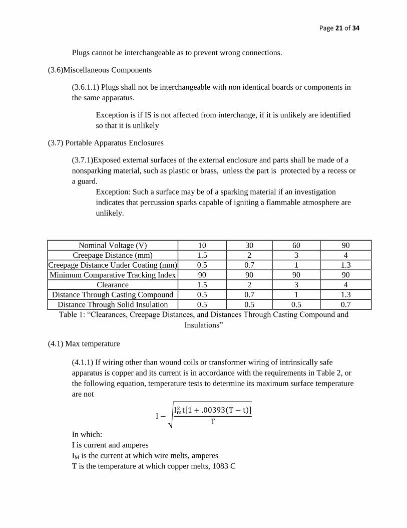
Nominal Voltage (V) 10 30 60 90
Creepage Distance (mm) 1.5 2 3 4
Creepage Distance Under Coating (mm) 0.5 0.7 1 1.3
Minimum Comparative Tracking Index 90 90 90 90
Clearance 1.5 2 3 4
Distance Through Casting Compound 0.5 0.7 1 1.3
Distance Through Solid Insulation 0.5 0.5 0.5 0.7
Table 1: “Clearances, Creepage Distances, and Distances Through Casting Compound and
Insulations”
(4.1) Max temperature
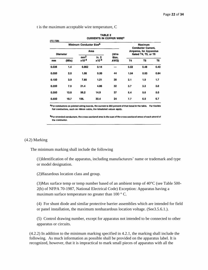
(4.1.1) If wiring other than wound coils or transformer wiring of intrinsically safe
apparatus is copper and its current is in accordance with the requirements in Table 2, or
the following equation, temperature tests to determine its maximum surface temperature
are not
In which:
I is current and amperes
IM is the current at which wire melts, amperes
T is the temperature at which copper melts, 1083 C
Page 22 of 34
t is the maximum acceptable wire temperature, C
(4.2) Marking
The minimum marking shall include the following
(1)Identification of the apparatus, including manufacturers’ name or trademark and type
or model designation.
(2)Hazardous location class and group.
(3)Max surface temp or temp number based of an ambient temp of 40°C (see Table 500-
2(b) of NFPA 70-1987, National Electrical Code) Exception: Apparatus having a
maximum surface temperature no greater than 100 ° C.
(4) For shunt diode and similar protective barrier assemblies which are intended for field
or panel installation, the maximum nonhazardous location voltage. (See3.5.6.1.).
(5) Control drawing number, except for apparatus not intended to be connected to other
apparatus or circuits.
(4.2.2) In addition to the minimum marking specified in 4.2.1, the marking shall include the
following. As much information as possible shall be provided on the apparatus label. It is
recognized, however, that it is impractical to mark small pieces of apparatus with all the
Page 23 of 34
required information. If this information is not on the apparatus, it shall be included in the
accompanying literature.
(1) For intrinsically safe apparatus:
(a) An indication that the apparatus is intrinsically safe;
(b) If investigated using the entity evaluation, the maximum input voltage, maximum
input current, maximum internal capacitance and maximum internal inductance;
(c) If repair is possible, a warning label worded "Warning - Substitution of Components
May Impair Intrinsic Safety;" and
(d) A reference to accompanying literature, that provides special installation, maintenance,
or operating instructions. If this information is not on the apparatus, it shall be included or
referenced on the control drawing.
(2) For associated apparatus:
(a) If investigated using the entity evaluation, the maximum output voltage, maximum
output current, maximum allowed capacitance, and maximum allowed inductance;
(b) If repair is possible, a warning worded "Warning - Substitution of Components May
Impair Intrinsic Safety;"
(c) Any other necessary information, in particular, an indication of any other type of
protection and its characteristics; and
(d) A reference to accompanying literature, that provides special installation, maintenance,
or operating instructions. If this information is not on the apparatus, it shall be included or
referenced on the control drawing.
4.2.3 Terminals, terminal boxes, and plugs and receptacles for connection to intrinsically safe
circuits shall be clearly identified and clearly distinguishable. If color only is used to comply
with this requirement, the color shall be light blue.
Comparison Procedure for Determining Spark Ignition Capability
(5.1.3) [Resistive] Circuits
(a) These figures apply only to circuits having an output voltage-current plot that is a
straight line drawn between open circuit voltage and short-circuit current.
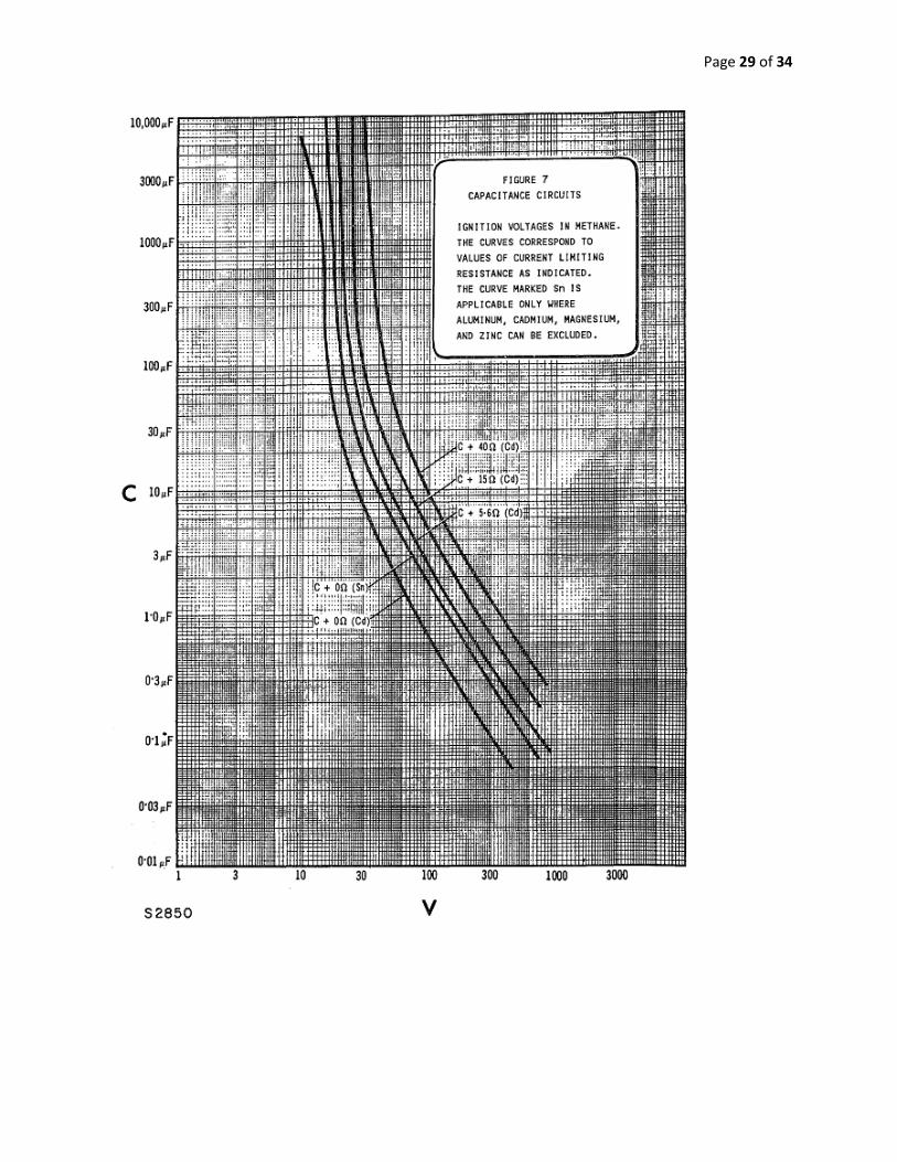
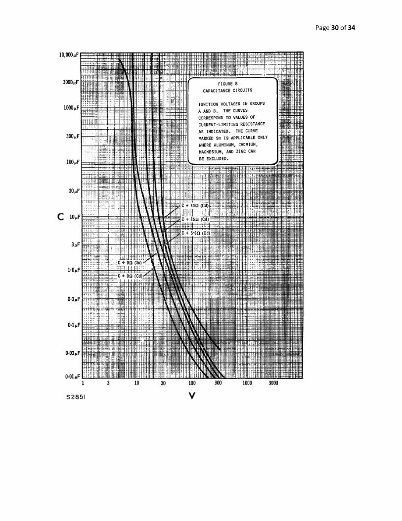
(5.1.5) [Resistive-Capacitive] Circuits
(a) Refer to Fig. 7 and 8. These curves represent capacitor discharge only. They do not
include the additional current which may be available from the associated apparatus.
Page 24 of 34
(5.2) Maximum Voltage and Current Levels
(5.2.1) The circuit conditions are to include all normal and fault conditions described in this
standard, excluding the 1.5 test factor.
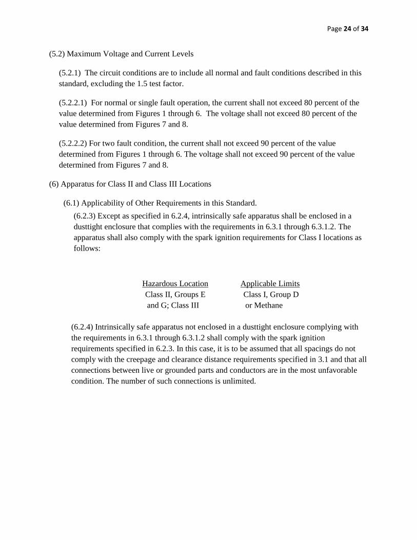
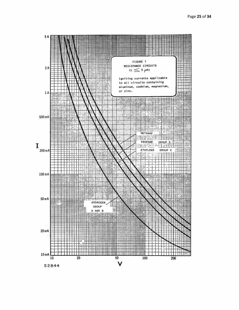
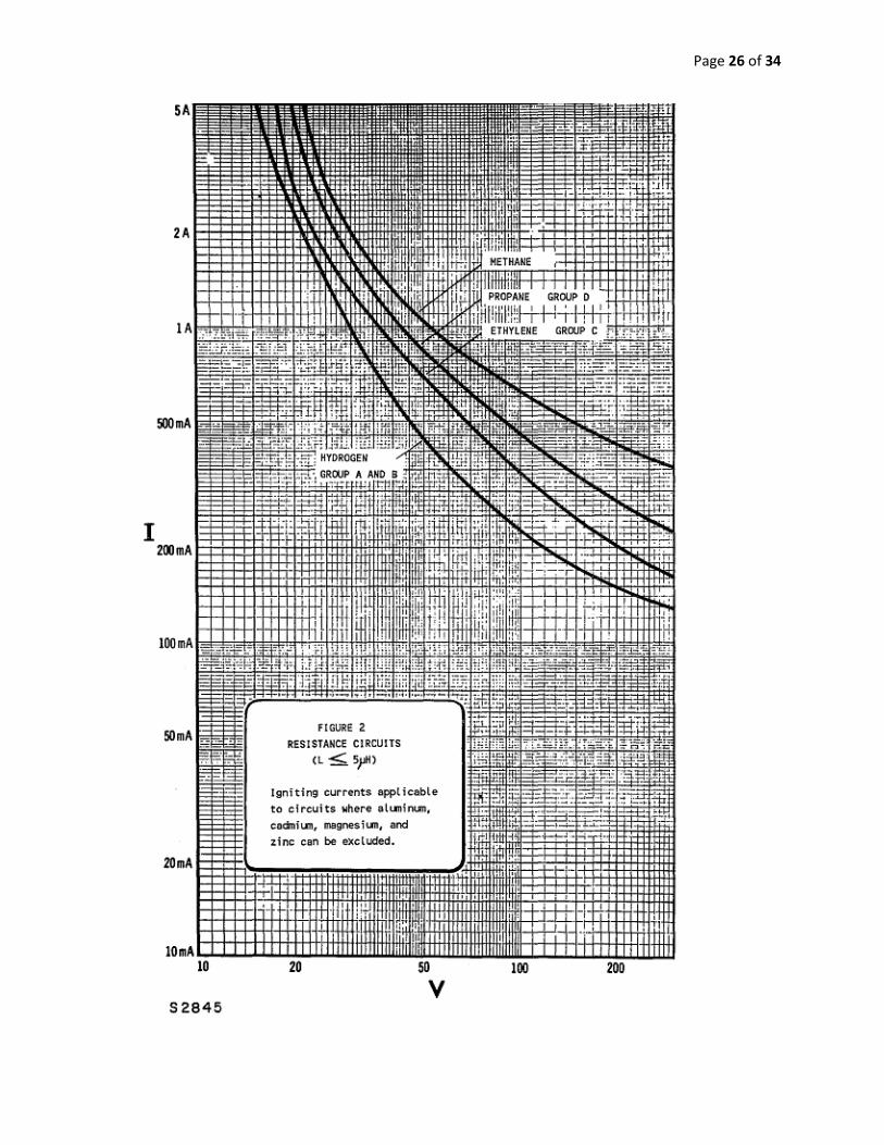
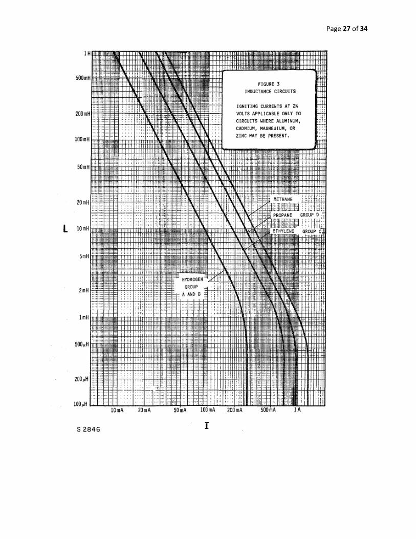
(5.2.2.1) For normal or single fault operation, the current shall not exceed 80 percent of the
value determined from Figures 1 through 6. The voltage shall not exceed 80 percent of the
value determined from Figures 7 and 8.
(5.2.2.2) For two fault condition, the current shall not exceed 90 percent of the value
determined from Figures 1 through 6. The voltage shall not exceed 90 percent of the value
determined from Figures 7 and 8.
(6) Apparatus for Class II and Class III Locations
(6.1) Applicability of Other Requirements in this Standard.
(6.2.3) Except as specified in 6.2.4, intrinsically safe apparatus shall be enclosed in a
dusttight enclosure that complies with the requirements in 6.3.1 through 6.3.1.2. The
apparatus shall also comply with the spark ignition requirements for Class I locations as
follows:
Hazardous Location Applicable Limits
Class II, Groups E Class I, Group D
and G; Class III or Methane
(6.2.4) Intrinsically safe apparatus not enclosed in a dusttight enclosure complying with
the requirements in 6.3.1 through 6.3.1.2 shall comply with the spark ignition
requirements specified in 6.2.3. In this case, it is to be assumed that all spacings do not
comply with the creepage and clearance distance requirements specified in 3.1 and that all
connections between live or grounded parts and conductors are in the most unfavorable
condition. The number of such connections is unlimited.
Page 25 of 34
Page 26 of 34
Page 27 of 34
Page 28 of 34
Page 29 of 34
Page 30 of 34
Page 31 of 34
Page 32 of 34
Page 33 of 34
Standard Regulations for Electrical Safety8:
In addition to the above specifications, more general installation and application
specifications are as follows.
1. Insulation Integrity:
Completed wiring installations shall be free from short circuits and from grounds other
than those required or permitted by this subpart.
2. Interrupting Rating:
Equipment intended to interrupt current at fault levels shall have an interrupting rating
sufficient for the nominal circuit voltage and the current that is available at the line terminals of
the equipment. Equipment intended to interrupt current at other than fault levels shall have an
interrupting rating at nominal circuit voltage sufficient for the current that must be interrupted.
3. Circuit Impedance and Other Characteristics:
The over current protective devices, the total impedance, the component short-circuit
current ratings, and other characteristics of the circuit to be protected shall be selected and
coordinated to permit the circuit protective devices used to clear a fault to do so without the
occurrence of extensive damage to the electrical components of the circuit. This fault shall be
assumed to be either between two or more of the circuit conductors, or between any circuit
conductor and the grounding conductor or enclosing metal raceway.
4. Internal Parts:
Internal parts of electrical equipment, including busbars, wiring terminals, insulators, and
other surfaces, may not be damaged or contaminated by foreign materials such as paint, plaster,
cleaners, abrasives, or corrosive residues.
5. Mounting Safety:
Electric equipment shall be firmly secured to the surface on which it is mounted. Wooden
plugs driven into holes in masonry, concrete, plaster, or similar materials are not considered
secure means of fastening electric equipment.
6. 600 Volts, Nominal, or Less (Space and Electric Equipment):
Sufficient access and working space shall be provided and maintained about all electric
equipment to permit ready and safe operation and maintenance of such equipment. Working
space for equipment likely to require examination, adjustment, servicing, or maintenance while
energized shall comply with the following dimensions, except as required or permitted elsewhere
in this subpart. Switchboards, panelboards, and distribution boards installed for the control of
light and power circuits, and motor control centers shall be located in dedicated spaces and
protected from damage.
8 http://www.osha.gov/pls/oshaweb/owadisp.show_document?p_table=STANDARDS&p_id=9880
Page 34 of 34
Additional Requirements not specified above due to time constraint.
1) Cables and cable fittings shall be designed following the regulations of UL 2225
2) Dust-tight and Dust-ignition proof equipment shall be designed following the regulations
of ISA 12.12.01
3) Any portable electric equipment shall be designed following the regulations of ISA
12.12.03
4) Other regulations that may need to be considered are as follows:
a) ISA 61241-0: Electrical Apparatus For Use In Zone 20, Zone 21 And Zone 22
Hazardous (Classified) Locations – General Requirements
b) ISA 61241-1: Electrical Apparatus For Use In Zone 21 And Zone 22 Hazardous
(Classified) Locations – Protection By Enclosures “ “TD”
c) ISA 61241-10: Electrical Apparatus For Use In Zone 20, Zone 21 And Zone 22
Hazardous (Classified) Locations – Classification Of Zone 20, Zone 21 And Zone 22
Hazardous (Classified) Locations.
d) ISA 61241-11: Electrical Apparatus For Use In Zone 20, Zone 21 And Zone 22
Hazardous (Classified) Locations – Protection By Intrinsic Safety “ID”
e) ISA RP12.06.01: Recommended Practice For Wiring Methods For Hazardous
(Classified)Locations Instrumentation Part 1: Intrinsic Safety
f) The following specification might be needed to test the sensor that is assumed to be
intrinsically safe:
ISA TR12.2: Intrinsically Safe System Assessment Using The Entity Concept