Class C Motorhome Owner’s Manual - Jayco Jayco Seneca OM Black... · Class C Motorhome Owner’s...
181
PRINTED ON RECYCLED PAPER 0181976.2017 2017 Class C Motorhome Owner’s Manual
-
Upload
nguyennguyet -
Category
Documents
-
view
219 -
download
0
Transcript of Class C Motorhome Owner’s Manual - Jayco Jayco Seneca OM Black... · Class C Motorhome Owner’s...
2016 CAMPING TRAILERS
PRINTED ON RECYCLED PAPER0181976.2017
2017
Class C Motorhome
Owner’s Manual

THE JAYCO ECOADVANTAGE IS OUR COMPANY’S COMMITMENT
TO PROTECTING THE ENVIRONMENT. Through Jayco’s company-wide
sustainability program, we’re creating better ways to build better RV’s using
fewer natural resources. Already, our initiative has created significant impact.
As of 2014 our company has:
Recycled
Conserved
Saved
We’re proud of our results, and we know those numbers show that a little
initiative can go a long way. The Jayco EcoAdvantage is our way of making
sure endless generations can enjoy the Great Outdoors.
● 7,192 tons of wood ● 2,354 tons of scrap metal ● 1,428 tons of cardboard and paper
● 9,997,400 gallons fo fresh water, enough to meet the daily needs of 133,293 Americans.
● 34,277 gallons of gas, enough for Americans to drive more than 957,600 miles.
● Enough electricity to power 1,745 homes for tha year.
● 60,900 mature trees. ● Enough landfill airspace to meet the annual disposal
needs of a community of 44,683 people.
2017 Jayco Seneca Class C Motorhome

Table of ContentsSection 1: Warranty & Service
About This Manual 3Chassis Guide 3Warranty packet 3Safety Alerts 3Reporting Safety Defects 4Manufacturing Process 5Options & Equipment 5Customer Responsibility 6Change Of Address/Ownership 6Dealer Responsibility 6Suggestions For Obtaining Service 6Customer Relations 7Jayco Travel Club 8JayPlus™ Extended Service Contract 8Jayco Customer First Emergency Roadside Assistance 8Obtaining Emergency Warranty Repair 9Obtaining Service For Separately Warranted Items 10Obtaining Service at Jayco 10Parts & Accessories 11Notice To Jayco Dealers 15
Section 2: Occupant SafetySecondary Means of Escape (Exit Window) 19
Exit Window Label 19Fire Safety 20Fire Extinguisher 21Smoke Alarm 21Combination Carbon Monoxide/ Propane Alarm 23
Smoke detector warning label 23Formaldehyde 27Extended Or Full Time Usage 27Cold Weather Usage 27Condensation 27
Section 3: Pre-travel informationVehicle Labels 29
Weight Terms 29Upper section Federal OCCC weight labels 30Lower section Federal OCCC weight labels 30Federal Certification Label 30
Weight and Capacity Labels 30Loading Your Motorhome 31Trailer Plug 32Weighing Your Motor home 32
7-way trailer plug 32Section 4: Vehicle Operation
Vehicle Operation 35Using The Rear Hitch 35
Towing and braking label 35Braking & Stopping 36
Parking Brake 37Power Entry Door Step 37Entrance Door Step(s) 37Entrance Door 37
Table of Contents
RV Step 37Keys 38Keyless Entry (if so equipped) 38
Battery powered keyless entry system: 38Driver & Passenger Seat 41Seat Belts 42Child Safety Restraint Systems 42Outside Rearview Mirrors 43Rear Vision Camera 43Backing Up 44Campsite Hook-Up 44Hydraulic Leveling System 45
Hydraulic Jack Pad 46Emergency Stopping 49Emergency Towing 49Front Axle Tire Alignment 50Wheel Lug Nuts/Wheel Liners 50Tires 51Changing A Tire 53Patio Awning 53Operating Power Awnings (If So Equipped) 54
Carefree® LONGITUDE Awnings (If So Equipped) 54Awning care 54Adjusting the Awning Pitch 55Emergency Operation 56
Section 5: Slideout SystemsElectric Slide Room(s) 59
Troubleshooting the Slideout 59Slideout Systems 60
Schwintek Inwall slideout system 60Retracting slideout room 60Trouble shooting the Inwall slideout system 61Manual override for the inwall slideout 61Flush Floor Slideout 64Trouble shooting the flush floor slideout 64Manual Operation for the flush floor slideout 64Power Gear® Slideout 65
Fig. 1-Through Frame Crank Extension w/pin. 65Fig. 3-Hex Head Crank Extension 65Fig. 2-Crank Handle 65Fig. 4-Ratchet 65
Manual Operation for the Power Gear slideout system 67Norco Slideout 69Manually Moving The Room – Norco slideout 69Power Gear® Slim Rack Slideout System 70Operating the Slideout 70
Fig.1 Slideout Controller 70Emergency Retract Mode: 73Manually Retract Room with Ratchet & Socket: 73
Section 6: Electrical SystemThe Electrical System 77In Case Of An Electrical Fire 77Controls and Switches 77Command Center 78
Table of ContentsCommand Center Panel 78Mounted to wall 78
GFCI Receptacle 79Testing the Campsite Power Connection 79Connecting the Power Cord 80Inverter (If so Equpped) 80Converter 81
Inspection and maintenance 8112-volt DC System 81
Wizard Button & Reverse 81 Protection Fuses 81
12-volt Fuse Panel 82Replacing a fuse 82
12-Volt DC Outlet 82Batteries 83
House Batteries 83Dry camping 83Battery inspection & care 84Battery storage instructions 84Battery replacement 84
Auxiliary Start System 85Isolator Solenoid 8512-Volt Battery Disconnect 85Load Center 86Approximate Electrical Load Ratings 86
Typical Load Center Exterior Panel 86Load Center Panel w/120 volt Main breaker 86
120-volt (50 AMP) AC System (If So Equipped) 8750-amp Power Cord (If So Equipped) 88Calculating 50 AMP Electrical Load (If So Equipped) 88120-volt Circuit Breakers 89
Before starting the generator 91Magnum® Standalone AGS 91AGS Controller 91
AGS Controller 91Command Center Panel 92
Replacing Light Bulbs 93Section 7: Fuel & Propane System
Diesel Fuel & Fill 95Fuel selection 95DEF Fluid 95
Fuel Safety 96Fuel selection 96Fuel filler cap 97Filling the fuel tank 97Fuel Economy 97
Exhaust Gas Fumes 97Propane Gas System (If so equipped) 98
Maintenance 99Propane Leak Test 99
Propane label 99Propane Safety Procedure 100Propane Gas Container 100
Propane system label 100
Table of Contents
Servicing or filling 101LP gas container overfill 101
ASME Tank 101Using The Propane System 102Calculating Propane Gas Usage 102
“Do not fill to more than 80%” label 102Cooking With Propane Gas 103Traveling with Propane 104
Refueling warning label 104Ensure a supply of fresh air (Canada units only) 104Cooking / comfort heating label 104
Section 8: Plumbing SystemPlumbing System Maintenance 105Monitor Panel (If So Equipped) 105
Monitor Panel 105(Monitor panel appearance and components listed may vary) 105Command Center Panel 105
Fresh Water System 106Fresh Water Holding Tank 10712-Volt Water Pump & Switch 107Water Pressure Regulator (customer Supplied) 108
Water Pump 108Utility Center 109
Potable water only label 110City Fixtures 110City Fill Tank 111Country Fill 111
Water Purification System (If So Equipped) 112Normal Setting 112Sanitize Tank 112Sanitize / Winterize Lines 112To Replace Canister Filter Cartridge 113
Filter housing 113Water Heater 114
Tank (Storage) Water Heater System(If So Equipped) 114Gas/Electric DSI Tank (Storage) Water Heater (If So Equipped) 114
Anode rod 116Replacement chart 116
TANKLESS WATER HEATER (If So Equipped) 118Water Heater Bypass – 3 Valves (If So Equipped) 120
Factory installed water heater bypass 120Outside Shower (If So Equipped) 120Faucets 121Bathroom Tub / Shower 121Hardware & Sink or Shower Fixtures 122Draining The Fresh Water System 122
Exterior FreshWater 122Drain 122
Sanitizing the Plumbing System 123When to sanitize 123How to sanitize 123
Low Point Drain 123Winterization 125
Table of ContentsBlack/Grey Water System 127Black/Grey Water Holding Tanks 127Black & Grey Tank Drains 128
Dump Station Connector 129Garden hose connection 129Electric Dump Valves 129Macerator power switch 129
Black Tank Flush (If So Equipped) 130Black Tank Flush Inlet 130Macerator Bypass 130
Toilet 131Section 9: Heating & Cooling
Air Conditioner 133Power Roof Vent (If So Equipped) 133
Attic Fan Control 133Furnace 134
Section 10: AppliancesConvection Microwave 135Induction Cooktop (If So Equipped) 135Range Hood (If So Equipped) 138Cooking With Propane 138In Case Of A Grease Fire 138Refrigerator 138
Range Hood Vent 138Cleaning Your Refrigerator 139
Cleaning the interior 139Washer/Dryer Prep (If So Equipped) 140
Dryer vent label 140Cleaning the exterior 140
Water Heater – See plumbing section 141Section 11: Electronics
Satellite Dish (if so equipped) 143HDTV Antenna (If So Equipped) 144
HDTV antenna 144Enclosure Base 144
Exterior Television (if so equipped) 145Winegard HDTV antenna 145Interior base 145
Secion 12: InteriorCleaning The Interior 147Décor Items 147
Décor Glass (if so equipped) 147Furniture Upholstery 147Window treatments 147Window Shades 147
Sofa 148Hide-a-bed Sofa or Sofa Sleeper 148Jack Knife Sofa 148Trifold Sofa 149
Free Standing Dinette Chairs (If So Equipped) 149Booth Dinette (If So Equipped) 149Cabinetry & Tables 150
Booth Dinette 150
Dream Dinette 150Countertops 151
Laminate countertops (if so equipped) 151Solid surface countertops (if so equipped) 151
Interior Wall Panel 152Flooring 152
Carpet 152Vinyl flooring 152
Ceiling Fabric 153Privacy Drape Installation 153Bed Storage 153ABS Plastics 153
Section 13: ExteriorCleaning The Exterior 155Frame 157Chassis Maintenance 157Front Axle Tire Alignment 157Exterior Roof & Sidewall Vents 158Windows 158Exterior ladder (If So Equipped) 158Sealants 159
Section 14: Travel/Camping/Storage ChecklistsRV Start-Up 161Ready To Leave Checklist 161Motor home Storage 162
Section 15: Additional InformationFeatured Components Quick Reference Chart 165Vehicle Maintenance Record 166
1
WARNING: Read all instructions in this manual and component
manufacturer supplied information before using your RV.
This manual has been provided by Jayco for the sole purpose of providing instructions concerning the operation and maintenance of this vehicle and its components. Nothing in this manual creates any warranty, either expressed or implied. The only warranty offered by Jayco is as set forth in the limited warranty applicable to this vehicle.
The owner’s failure to provide required service and/or maintenance could result in the loss of warranty. The owner should review the Jayco limited warranty and the limited warranties that apply to specific components that are offered with this vehicle.
Instructions are included in the manual for operating various components which are optional on some vehicles or may not be available on your particular model. “If so equipped” does not indicate or imply that the component(s) or option(s) were at any time available, or can be retrofitted to your model. In addition, the owner should refer to individual manufacturer’s operating instructions contained in the owner’s packet.

2
3
Section 1: Warranty & Service
Congratulations! Thank you for selecting a Jayco recreation vehicle. We are excited to welcome you to our growing RV family. Jayco is the largest privately held manufacturer of recreation vehicles in the world. We are committed to being the most respected name in RVs. We invite you to drop by our Visitors Center located in Middlebury, Indiana. To book a group tour or check our scheduled factory tour times (free admission, closed holidays) please call 1-800-RV-JAYCO.
About This ManualThis manual is a guide to operation of the features, equipment and controls in your motor home. If you find components in your motor home vary significantly from what is described, please contact your dealer to ensure you have the correct information. Nothing in this manual creates any warranty, either expressed or implied. The only warranty offered is as set forth in the Limited Warranty applicable to the motor home that you received prior to your purchase.
This Owner’s Manual, Owner’s Portfolio and Chassis Guide are to be considered permanent components of the vehicle and kept in the motor home at all times for personal reference. If the motor home is sold, they should remain with the vehicle for the next owner. Nothing in this manual creates any warranty, either expressed or implied, nor does it cover every possible detail of equipment, standard or option, installed on or in your motor home.
The descriptions, illustrations and specifications in this manual reflect the most current available to us at the time of publication, are subject to change and are not intended to indicate actual size.
Warranty packetThere are components that are excluded from the vehicle warranty, or are warranted separately by their own individual manufacturer’s limited warranty. The Warranty Packet contains these component manufacturer supplied manuals or information sheets, warranty cards and/or registrations. Consult this information for questions regarding operating, maintenance, servicing instructions and warranty coverage. It is important you complete and mail warranty cards and registrations within the prescribed time limits to avoid loss of warranty coverage.
Chassis GuideThroughout this manual, frequent reference is made to the vehicle’s Chassis Guide. The Chassis Guide includes the owner’s manual provided by the manufacturer of the chassis on which this motor home is built, warranty cards and/or registrations. It also includes pertinent information regarding the transmission, tires, etc. Consult the Chassis Guide for operating safety, maintenance, servicing instructions and warranty coverage.
Safety AlertsThroughout this manual, certain items are labeled NOTE, CAUTION, WARNING, and DANGER. These terms will alert you to precautions that can involve risk to your vehicle or to your personal safety.
Read and follow them carefully. National Safety Associations and organizations require many of the instructions listed. Always use the appropriate safety gear when servicing or maintaining your recreation vehicle. Please call your dealer or our customer service representatives if you are unsure how to proceed.
These signal words indicate precautions and potential situations, which if not avoided, may result in personal injury, property damage, or damage to your recreation vehicle. These
4
Section 1: Warranty & Service
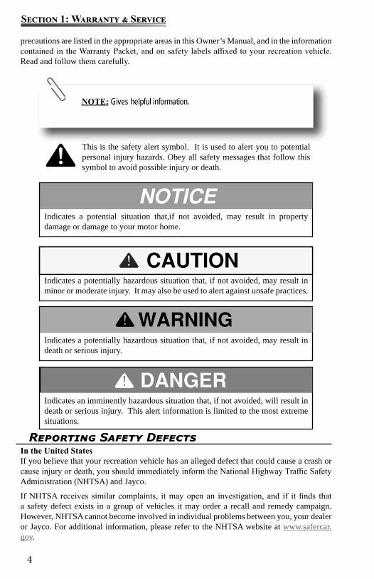
Indicates a potentially hazardous situation that, if not avoided, may result in minor or moderate injury. It may also be used to alert against unsafe practices.
Indicates an imminently hazardous situation that, if not avoided, will result in death or serious injury. This alert information is limited to the most extreme situations.
Indicates a potentially hazardous situation that, if not avoided, may result in death or serious injury.
NOTE: Gives helpful information.
Indicates a potential situation that,if not avoided, may result in property damage or damage to your motor home.
This is the safety alert symbol. It is used to alert you to potential personal injury hazards. Obey all safety messages that follow this symbol to avoid possible injury or death.
precautions are listed in the appropriate areas in this Owner’s Manual, and in the information contained in the Warranty Packet, and on safety labels affixed to your recreation vehicle. Read and follow them carefully.
Reporting Safety DefectsIn the United StatesIf you believe that your recreation vehicle has an alleged defect that could cause a crash or cause injury or death, you should immediately inform the National Highway Traffic Safety Administration (NHTSA) and Jayco.
If NHTSA receives similar complaints, it may open an investigation, and if it finds that a safety defect exists in a group of vehicles it may order a recall and remedy campaign. However, NHTSA cannot become involved in individual problems between you, your dealer or Jayco. For additional information, please refer to the NHTSA website at www.safercar.gov.
5
Section 1: Warranty & Service
To contact NHTSA by phone:Call the Department of Transportation (DOT) Vehicle Safety Hotline at 1-888- 327-4236 and a NHTSA representative will record your complaint information (TTY: 1-800-424-9153 or 1-202-484-5238).
To contact NHTSA by mail:Office of Defects Investigations/CRDNVS-2161200 New Jersey Ave. SEWashington, DC 20590
In CanadaIf you believe your recreation vehicle has an alleged safety defect, you should contact Transport Canada and Jayco. Transport Canada prefers to be called instead of posted mail or email as it enables their investigators to confirm that your information is correct, and to answer your questions accurately. For additional information, please refer to the Transport Canada website at www.tc.gc.ca.
To contact Transport Canada by phone:Call 1-800-333-0510 (or 1-613-993-9851 if you are calling from the Ottawa region) and ask to speak to a defect investigator.
To contact Transport Canada by mail:Road Safety and Motor VehicleRegulation DirectorateTransport CanadaTower C, Place de Ville330 Sparks StreetOttawa, Ontario K1A 0N5
Manufacturing ProcessJayco recreation vehicles are manufactured for use as temporary living quarters for recreation, camping and travel uses, all as defined by the bylaws of the Recreation Vehicle Industry Association (RVIA).
This recreation vehicle is not intended for use as a full-time residence or for commercial use. Commercial use means using the recreation vehicle as a business asset such as a mobile office or using the recreation vehicle for lease or rental purposes.
Jayco reserves the right to discontinue or change specifications or design at any time without notice and without incurring any obligation whatsoever. Recreation vehicles built for sale in Canada may differ to conform to Canadian Codes.
Options & EquipmentJayco recreation vehicles are available in several sizes and models, so accessories and components may differ slightly between models. Some equipment described in this manual may not apply to your recreation vehicle.
Jayco reserves the right to discontinue or change specifications or design at any time without notice, and to make additions or improvements without incurring any obligations upon itself to install these changes on its products previously manufactured. Recreation vehicles built for sale in Canada may differ to conform to Canadian Codes.
6
Section 1: Warranty & Service
Customer ResponsibilityIt is important you read and understand all instructions and precautions before operating the recreation vehicle. Even if you are an experienced RV’er we encourage you to thoroughly read this Owner’s Manual, as well as the information contained in your Warranty Packet.
As technology advances, new improvements enter the RV industry every day, and each RV manufacturer has its own unique manufacturing process.
Familiarize yourself with the applicable warranties. There are components that are excluded or warranted separately by their individual manufacturer’s limited warranty (refer to the Warranty Packet).
As the owner of the recreation vehicle, you are responsible for regular and proper maintenance performed in accordance with this manual and the OEM manuals. Regular and proper maintenance will help prevent conditions arising from neglect that are not covered by warranty. It is your responsibility and obligation to return your recreation vehicle to your dealer for warranty service repair.
Change Of Address/OwnershipPlease notify Jayco Customer Service as soon as possible of a change of address by writing or calling us. For notification of a change of ownership, please fill out the appropriate form located in this manual and mail it to Jayco Customer Service along with documentation showing proof of ownership. Please include your current vehicle mileage (motorized only).
Dealer ResponsibilityAt the time of sale of the new recreation vehicle, your Jayco dealer is expected to:
Deliver your recreation vehicle in the best condition possible. Your recreation vehicle must pass the dealer’s pre-delivery inspection (PDI), including all systems tests.
Provide orientation of the recreation vehicle, its systems, components and operation. Request that you read all warranty information and explain any provision not clearly
understood. Ensure you receive the Warranty Packet. Your dealer can assist you in completing the
OEM warranty cards or registrations, and locate any required component model or serial numbers.
Complete and return the “Warranty Registration and Customer Delivery Form” to Jayco within 10 days of delivery to activate the applicable warranty coverage.
The Limited Warranty is activated only after Jayco receives a signed and dated “Warranty Registration and Customer Delivery Form” from your dealer.
Suggestions For Obtaining ServiceTo help ensure your dealer provides the level of service you expect, here are some suggestions we would like to make:
Contact your dealer at once… Do not wait until you are ready to use your RV. Your dealer may not be able to service it immediately and/or the repair may require parts be ordered. The dealer’s service department is busiest on Mondays, Fridays and before the holidays.
Prepare for the appointment… If you are having warranty work performed, be sure to have the right papers with you. Take your warranty folder and have your vehicle information available. All work to be performed may not be covered by the warranty. Discuss additional charges with the service personnel.
7
Section 1: Warranty & Service
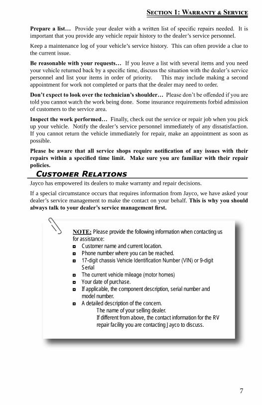
NOTE: Please provide the following information when contacting us for assistance:
◘ Customer name and current location. ◘ Phone number where you can be reached. ◘ 17-digit chassis Vehicle Identification Number (VIN) or 9-digit
Serial ◘ The current vehicle mileage (motor homes) ◘ Your date of purchase. ◘ If applicable, the component description, serial number and
model number. ◘ A detailed description of the concern.
The name of your selling dealer. If different from above, the contact information for the RV repair facility you are contacting Jayco to discuss.
Prepare a list… Provide your dealer with a written list of specific repairs needed. It is important that you provide any vehicle repair history to the dealer’s service personnel.
Keep a maintenance log of your vehicle’s service history. This can often provide a clue to the current issue.
Be reasonable with your requests… If you leave a list with several items and you need your vehicle returned back by a specific time, discuss the situation with the dealer’s service personnel and list your items in order of priority. This may include making a second appointment for work not completed or parts that the dealer may need to order.
Don’t expect to look over the technician’s shoulder… Please don’t be offended if you are told you cannot watch the work being done. Some insurance requirements forbid admission of customers to the service area.
Inspect the work performed… Finally, check out the service or repair job when you pick up your vehicle. Notify the dealer’s service personnel immediately of any dissatisfaction. If you cannot return the vehicle immediately for repair, make an appointment as soon as possible.
Please be aware that all service shops require notification of any issues with their repairs within a specified time limit. Make sure you are familiar with their repair policies.
Customer RelationsJayco has empowered its dealers to make warranty and repair decisions.
If a special circumstance occurs that requires information from Jayco, we have asked your dealer’s service management to make the contact on your behalf. This is why you should always talk to your dealer’s service management first.
8
Section 1: Warranty & Service
Mailing address Shipping addressJayco, Inc. Jayco, Inc.Customer Service Customer ServiceP.O. Box 460 100 Bontrager Drive903 S. Main Street Bldg 42 Door 4220Middlebury IN 46540 Middlebury IN 46540Phone (toll-free) (800) 283-8267Phone (local) (574) 825-0608Fax (toll-free) (866) 709-9139Brochure request [email protected] email [email protected] email [email protected] www.Jayco.com
An important note about alterations and warrantiesInstallations or alterations to the original equipment vehicle as distributed by Jayco are not covered by the Jayco Limited Warranty. The special body company, assembler, equipment installer or up fitter is solely responsible for warranties on the body or equipment and any alterations (or any effect of the alterations) to any of the parts, components, systems or assemblies installed by Jayco. Jayco is not responsible for the safety or quality of design features, materials or workmanship of any alterations by such suppliers.
Jayco Travel ClubAll owners of Jayco recreation vehicles are eligible for membership in the Jayco Travel Club. The club promotes family camping and the active use of your RV with others who have similar interests in the RV lifestyle.
One “International Rally” is held each year in various locations around the United States and Canada. In addition, the club offers a variety of local and regional activities throughout the year.
By belonging to the Jayco Travel Club, you will find new ways to enjoy your RV and make friends all across the country.
For more information, please visit www.Jaycorvclub.com or call 1-800-262-5178.JayPlus™ Extended Service Contract
Don’t let unexpected repair costs keep you from traveling toward your dreams. Protect yourself with a JayPlus™ Extended Service Agreement. For more information, contact your dealer or call 1-800-527-3426.
Your dealer can help you obtain a JayPlus™ insurance quote from GMAC Insurance or call 1-877-484-2261 (Savings Code: GL 2A).
Jayco Customer First Emergency Roadside Assistance
Jayco has teamed up with Coach Net, the largest RV emergency road service in the country to give you 24 hour, 7 days a week assistance in obtaining dependable service when and where you need it. We are offering this free of charge for the first year of ownership from the date of purchase (certain restrictions apply*).
9
Section 1: Warranty & Service
Obtaining Emergency Warranty RepairA roadside emergency can happen at any time, whether your recreation vehicle is new or old. If you are traveling, using the following guidelines can help get you back on the road faster.
1. Call 1-800-RV-JAYCO or use our website dealer locator to find an authorized Jayco dealer in your area. Contact them for an appointment; they will handle all warranty repair billing and returned parts for you.
2. If you cannot locate an authorized Jayco dealer near you, ask the campground staff for referrals or check the local telephone yellow pages. Or contact Jayco Customer Service or your selling dealer for assistance in locating a repair facility.a. Contact the RV repair facility to discuss your situation and make an appointment.
Ask how their billing will be handled. They may choose to bill Jayco directly; otherwise, you are expected to pay them.
b. Have the RV repair facility inspect your RV. Either they or you must call Jayco Customer Service to discuss applicable warranty coverage prior to any repair work being performed.
c. Jayco Customer Service will issue an authorization number upon warranty repair approval and advise if any original parts need to be returned.
d. Once Jayco Customer Service has issued an authorization number, the RV repair facility may begin actual repair to your RV.
e. Inspect the completed repair work thoroughly. If you are not satisfied, communicate that immediately to the RV repair facility management. Make sure you are satisfied with the repair before you pay or leave the premises.
f. For reimbursement, either you or the RV repair facility must send a copy of your itemized repair bill and all requested return parts by UPS (regular ground, freight pre-paid) within 60 days of the completed repair date.
To expedite processing your warranty claim, include your name, address, phone number, RV 17-digit VIN and authorization number. If returning parts, include a copy of your return freight bill.
OBTAINING WEEKEND OR AFTER BUSINESS HOURS REPAIR ASSISTANCE
If an authorized Jayco dealer is not located nearby, contact your selling dealer for assistance. If your dealer is closed, check with the campground staff or telephone yellow pages for an RV repair facility. Have the item repaired and contact Jayco Customer Service immediately the following business day.
You may continue your Customer First Roadside Assistance benefits in the following years by contacting Coach Net to discuss any applicable terms and rates for this independently continued coverage at 1-877-801-0333.
For further details and instructions on how to access your Roadside Assistance benefits, please refer to your Member Benefit Guide which will be mailed 6-8 weeks from the date the completed Warranty Registration and Customer Delivery Form is received by Jayco, or by contacting Coach-Net (www.coach-net.com) at 1-877-801-0333.
*To qualify for coverage, your RV must be eligible as set forth under the terms of the applicable “Limited Warranty” offered by Jayco.
10
Section 1: Warranty & Service
Obtaining Service For Separately Warranted Items
Your selling dealer is responsible for servicing your recreation vehicle before delivery, and has an interest in your continued satisfaction. We recommend your dealer perform all inspection, warranty and maintenance services. Some dealers may be authorized service centers for those OEMs whose products are warranted separately and excluded from the Limited Warranty.
Obtaining Service at JaycoShould your RV be in need of service, and your dealer recommend that the repairs be made at the Jayco Factory Service Center, your RV may be returned to us with the following guidelines*:
You or your dealer must make a confirmed appointment a minimum of 60 days prior to dropping off your RV at the Jayco Factory Service Center.
The holding tanks must be emptied and rinsed. We have a dumping station available for customer use.
The propane system and all electrical systems must be shut down and turned off. We are not responsible for discharged batteries or propane tanks.
During the appropriate season, please ensure your RV is winterized. Unless prior approval has been obtained from the Jayco Factory Service Center, all
personal items must be removed from the area where you are requesting service repair and the refrigerator emptied. We are not responsible for loss of food items.
All transportation costs are the responsibility of the owner. You may need to arrange for alternative accommodations for some types of repairs. Please be prepared accordingly
*Jayco Customer Service occasionally utilizes local independent repair facilities. Your RV may be referred to or repaired by one of these local repair facilities.
Failure to contact Jayco Customer Service, unauthorized or improper warranty repairs, or failure to return requested original parts may result in loss of reimbursements and/or loss of warranty.
11
Section 1: Warranty & Service
Parts & AccessoriesContact your independent Jayco dealer for assistance in obtaining replacement parts or accessories. Jayco does not sell parts retail direct or to non-authorized dealers. If the original part is no longer available, Jayco makes every effort to provide an appropriate substitute.
MOTORIZED LIMITED WARRANTYWHAT AND WHO IS COVERED The Jayco warranty covers the “house portion” of this recreational vehicle (“RV”), when used only for its intended purpose of recreational travel and camping, for two (2) years, or the first twenty-four thousand (24,000) miles of use, whichever occurs first. It covers RV’s that are sold in, and remain in, the United States, U.S. Territories and Canada, only. The house portion means the living area of the RV assembled by Jayco. The warranty period begins on the date that the RV is delivered to the first retail purchaser by an independent, authorized dealer of Jayco, or, if the dealer places the vehicle in service prior to retail sale, on the date the RV is first placed in such service. In the event that a substantial defect in material or workmanship, attributable to Jayco, is found to exist during the warranty period, it will be repaired or replaced, at Jayco’s option, without charge to the RV owner, in accordance with the terms, conditions and limitations of this limited warranty.
This limited warranty applies to the first consumer purchaser only. All rights and limitations within this warranty are applicable to the original owner of the RV only. Jayco’s limited warranty only covers substantial defects in materials, components, or parts of the RV attributable to Jayco. It does not replace, modify, or apply to the warranties provided by the manufacturers that supply the products used by Jayco to assemble the RV, like the chassis. You may contact an independent, authorized dealer for details.
Jayco’s obligation to repair or replace defective materials or workmanship is the sole obligation of Jayco under this limited warranty. Jayco reserves the right to use new or remanufactured parts of similar quality to complete any work, and to make parts and design changes from time to time without notice to anyone. Jayco reserves the right to make changes in the design or material of its products without incurring any obligation to incorporate such changes in any product previously manufactured. Jayco makes no warranty as to the future performance of this RV, and this limited warranty is not intended to extend to the future performance of this RV, or any of its materials, components or parts. In addition, the RV owner’s obligation to notify Jayco, or one of its independent, authorized dealers, of a claimed defect does not modify any obligation placed on the RV owner to contact Jayco directly when attempting to pursue remedies under state or federal law.
LIMITATIONS, EXCLUSIONS AND DISCLAIMER OF IMPLIED WARRANTIES
ANY IMPLIED WARRANTY THAT IS FOUND TO ARISE BY WAY OF STATE OR FEDERAL LAW, INCLUDING ANY IMPLIED WARRANTY OF MER-CHANTABILITY OR ANY IMPLIED WARRANTY OF FITNESS, IS LIMITED IN DURATION TO THE DURATION SET FORTH IN THIS LIMITED WARRANTY AND IS LIMITED IN SCOPE OF COVERAGE TO THE SCOPE OF COVERAGE OF THIS LIMITED WARRANTY.Jayco makes no warranty of any nature beyond that contained in this limited warranty. Jayco does not authorize any person to create any other obligation or liability for it regarding this RV, and Jayco is not responsible for any representation, promise or warranty made by any dealer or other person beyond what is expressly stated in this limited warranty, and no one has the authority to enlarge, amend or modify this limited warranty. Any selling or servicing
12
Section 1: Warranty & Service
dealer is not Jayco’s agent, but an independent entity.
JAYCO SHALL NOT BE LIABLE FOR ANY INCIDENTAL OR CON-SEQUENTIAL DAMAGES THAT MAY RESULT FROM BREACH OF THIS LIMITED WARRANTY OR ANY IMPLIED WARRANTY. THIS EXCLUSION OF CONSEQUENTIAL AND INCIDENTAL DAMAGES SHALL BE INDEPENDENT OF ANY FAILURE OF THE ESSENTIAL PURPOSE OF ANY WARRANTY, AND THIS EXCLUSION SHALL SURVIVE ANY DETERMINATION THAT THIS LIMITED WARRANTY OR ANY IMPLIED WARRANTY HAS FAILED OF ITS ESSENTIAL PURPOSE. Some states do not allow limitations on how long an implied warranty lasts, or the exclusion or limitation of incidental or consequential damages, so the above limitations or exclusions may not apply to you.
HOW TO GET SERVICETo obtain warranty service the owner must do all of the following:
1. Notify an independent, authorized dealer of Jayco, or Jayco, of the substantial defect in material or workmanship attributable to Jayco, within the warranty coverage period designated above;
2. Provide the notification mentioned in (1), above, within ten (10) days of when the owner discovered, or should have discovered, the substantial defect in material or workmanship attributable to Jayco;
3. Promptly schedule an appointment with and take the RV to an independent, authorized dealer of Jayco, or Jayco, for repairs; and
4. Pay any freight or transportation costs, import duties, fees and all incidental expenses associated with obtaining warranty service.
For warranty service simply contact one of Jayco’s independent, authorized service centers for an appointment and then deliver your RV to the service center on the specified appointment date. If you need assistance you may contact Jayco, at 903 S. Main Street, P.O. Box 460, Middlebury, Indiana 46540, Attn: Customer Service, (574) 825-5861, (800) 283-8267 or www.jayco.com.
NOTE: Jayco does not control the scheduling of service work at the independent, authorized dealerships. You may encounter some delay in scheduling or completion of work. Also, you must notify the selling dealer at time of delivery to have work performed on any defect that occurred at the factory during manufacture at no cost to you as provided by this limited warranty. (See below under WHAT IS NOT COVERED).
If two (2) or more service attempts have been made to correct any covered defect that you believe impairs the value, use or safety of the RV, or if it has taken longer than thirty (30) days for those types of repairs to be completed, you must, to the extent permitted by law, notify Jayco directly, in writing, at the above address, of the unsuccessful repair(s) of the alleged defect(s) so that Jayco can become directly involved in making sure that you are provided service pursuant to the terms of this limited warranty.
WHAT IS NOT COVERED
By way of example only, this limited warranty does not cover any of the following: defects in materials, components or parts of the RV not attributable to Jayco; items that are added or changed after the RV leaves the possession of Jayco; additional equipment or accessories installed at any dealership, or other place of business, or by any other party,
13
Section 1: Warranty & Service
other than Jayco; any RV used for rental or other commercial purposes (Note: It shall be concluded that the RV has been used for commercial and/or business purposes if the RV owner or user files a tax form claiming any business or commercial tax benefit related to the RV, or if the RV is purchased, registered or titled in a business name); any RV sold or used outside the United States, U.S. Territories or Canada; any RV not used solely for recreational travel and camping; any RV purchased through auction or wholesale; any RV purchased from a dealer that is not an authorized dealer of Jayco; normal wear, tear or usage, such as tears, punctures, soiling, mildew, fading, or discoloration of exterior plastic or fiberglass, or soft goods, such as upholstery, drapes, carpet, vinyl, screens, cushions, mattresses and fabrics; the effects of condensation or moisture from condensation inside the RV or failure to provide adequate ventilation; mold or any damage caused by mold to the inside or outside of the RV; imperfections that do not affect the suitability of the RV for its intended purpose of recreational use or items that are working as designed but that you are unhappy with; problems, including water leaks, related to misuse, mishandling, neglect or abuse, including failure to maintain the RV in accordance with the owner’s manual, or other routine maintenance such as inspections, lubricating, adjustments, tightening of screws and fittings, tightening of lug nuts, sealing, rotating tires; damage due to accident, whether or not foreseeable, including any acts of weather or damage or corrosion due to the environment, theft, vandalism, fire, or other intervening acts not attributable to Jayco; service items such as windshield wiper blades, lubricants, fluids, filters, etc.; damage resulting from tire wear or tire failure; defacing, scratches, dents, chips on any surface or fabric of the RV; damage caused by off road use, overloading the RV or alteration of the RV, or any of its components or parts; wheel alignment or adjustments to axles when caused by improper maintenance, loading or damage from road hazards, including off road travel, wheel damage or balancing or damage from tire failures. Also, any costs associated with obtaining service, including by way of example, travel costs, are specifically excluded from the coverage of this warranty.
In addition, this limited warranty does not cover any material, component or part of the RV that is warranted by another entity, including, by way of example, the automotive chassis and power train, steering, handling, braking, wheel balance, muffler, tires, tubes, batteries, gauges, generator, hydraulic jacks, inverter, converter, microwave, television, DVD/CD player, radio, speakers, television, refrigerator, range, hot water heater, water pump, stove, carbon monoxide detector, smoke detector, propane detector, furnace or any air conditioner. (Note: The written warranty provided by the manufacturer of the component part is the direct responsibility of that manufacturer).
Defects and/or damage to interior and exterior surfaces, trim, upholstery and other appearance items may occur at the factory. These items are usually detected and corrected at the factory or by the selling dealer prior to delivery to the retail customer. You must inspect your RV for this type of damage when you take delivery. If you find any such defect or damage you must notify the selling dealer at time of delivery to have these items covered by this limited warranty and to have work performed on the items at no cost to you as provided by this limited warranty.
EVENTS DISCHARGING JAYCO FROM OBLIGATION UNDER WARRANTY
Certain things completely discharge Jayco from any obligation under this warranty and void it. By way of example, the following shall discharge Jayco from any express or implied warranty obligation to repair or replace any defect that results from: any rental or other commercial use or purchase of the RV (as defined in this warranty), any RV sold outside of, or used outside of, the United States, U.S. Territories or Canada,

14
Section 1: Warranty & Service
through an auction or wholesale or by a non-authorized dealer, any defect in a separately manufactured component part, owner neglect or failure to provide routine maintenance (See Owner’s Manual), unauthorized alteration, off road use, collision or accident, whether or not foreseeable, including any acts of weather or damage or corrosion due to the environment, theft, vandalism, fire, explosions, overloading in excess of weight ratings, and tampering with any portion of the RV, or any use of the RV as a semi-permanent or permanent home.
LEGAL REMEDIES Any action to enforce any portion of this limited warranty, or any implied warranty, shall be commenced within six (6) months after expiration of the warranty coverage period designated above. Any performance of repairs shall not suspend this limitation period from expiring. Any performance of repairs after the warranty coverage period has expired, or performance of repairs regarding anything excluded from coverage under this limited warranty shall be considered “good will” repairs, and they will not alter the express terms of this limited warranty, or extend the warranty coverage period or this limitation period. In addition, this warranty is not intended to extend to future performance, and nothing in this warranty, or any action of Jayco, or any agent of Jayco, shall be interpreted as an extension of the warranty period or this limitation period. Some states do not allow a reduction in the statute of limitations, so this reduction may not apply to you.
WARRANTY REGISTRATIONS Your warranty registration records should be completed and delivered to the manufacturers of component parts. The selling dealership will assist you in completing and submitting a delayed warranty start form for your chassis, which is included in your chassis paperwork, and in filling out the Jayco product warranty registration form. That form must be returned to Jayco within ten (10) days of your taking delivery of the RV. Your Jayco warranty will not be registered unless this warranty registration is completed and received by Jayco. Failure to file this warranty registration with Jayco will not affect your rights under this limited warranty as long as you can present proof of purchase, but it can cause delays in obtaining the benefits of this limited warranty, and it may inhibit any servicing facility’s ability to provide proper repairs and/or part replacement.
CARE AND MAINTENANCE It is the owner’s responsibility to perform proper care and maintenance of the RV, and to assure correct load distribution. For details regarding this, please see your Jayco owner’s manual and the owner’s manuals of the chassis manufacturer and other component part manufacturers. These outline various care and maintenance that is required to maintain your RV. Please review all manuals supplied with your RV, and contact your selling dealership or supplier of the component part if you have questions. Note: Failure to maintain the RV as noted in those manuals voids this limited warranty, and any damage to the RV as a result of your failure to perform such care, is not covered by this limited warranty.
THIS WARRANTY GIVES YOU SPECIFIC LEGAL RIGHTS, AND YOU MAY ALSO HAVE OTHER RIGHTS THAT VARY FROM STATE TO STATE.
JAYCO, INC.903 S. Main Street * P.O. Box 460 * Middlebury, IN 46540
Telephone: 574-825-5861 or 800-283-8267
15
Section 1: Warranty & Service
Notice To Jayco DealersThis Owner’s Manual contains the Towable Limited Warranty that applies to this RV. However, if the Jayco dealer decides to use this RV for rental purposes, then the Towable Limited Warranty will not apply to this RV. The Towable Limited Rental Warranty applies in that situation.
If, on the other hand, the Jayco dealer sells this RV to a retail customer then the rental warranty would not be applicable. The rental warranty does not apply to retail consumers.
Jayco’s rental program is applicable to the following product lines:
Redhawk Greyhawk Melbourne Seneca Precept Alante
If you have any questions regarding this, please contact Jayco Customer Service at (800) 283-8267 or (574) 825-0608.
JAYCO MOTORIZED RENTAL LIMITED WARRANTYWHAT AND WHO IS COVERED The Jayco warranty covers this recreational vehicle (“RV”), when used only for recreational travel and camping, including recreational travel and camping by renters of the Dealer, for one (1) year, or the first twelve thousand (12,000) miles of use. This limited warranty applies to the original Dealer only, and it is not transferable. The warranty period begins on the date that Dealer first places the RV in rental service. In the event that a substantial defect in material or workmanship, attributable to Jayco, is found to exist during the warranty period, Jayco will reimburse the Dealer either the reasonable costs of repair or the reasonable costs of replacement of the defect, (Jayco’s option), in accordance with the terms, conditions and limitations of this limited warranty.
Jayco’s obligation to reimburse Dealer for the reasonable costs of repair or replacement of defective materials or workmanship is the sole obligation of Jayco under this limited warranty. Jayco reserves the right to use new or remanufactured parts of similar quality to complete any work, and to make parts and design changes from time to time without notice to anyone. Jayco reserves the right to make changes in the design or material or its products without incurring any obligation to incorporate such changes in any product previously manufactured. Jayco makes no warranty as to the future performance of this RV, and this limited warranty is not intended to extend to the future performance of this RV, or any of its materials, components or parts. In addition, the Dealer’s obligation to notify Jayco, of a claimed defect does not modify any obligation placed on the Dealer to contact Jayco directly when attempting to pursue remedies under state or federal law.
LIMITATIONS, EXCLUSIONS AND DISCLAIMER OF IMPLIED WARRANTIES
ANY IMPLIED WARRANTY THAT IS FOUND TO ARISE BY WAY OF STATE OR FEDERAL LAW, INCLUDING ANY IMPLIED WARRANTY OF MERCHANTABILITY OR ANY IMPLIED WARRANTY OF FITNESS, IS LIMITED IN DURATION TO THE DURATION OF THIS LIMITED WARRANTY AND IS LIMITED IN SCOPE OF COVERAGE TO THE SCOPE OF COVERAGE OF THIS LIMITED WARRANTY.
16
Section 1: Warranty & Service
Jayco makes no warranty of any nature beyond that contained in this limited warranty. Jayco does not authorize any person to create any other obligation or liability for it regarding this RV, and Jayco is not responsible for representation, promise or warranty made by any dealer or other person beyond what is expressly stated in this limited warranty, and no one has the authority to enlarge, amend or modify this limited warranty. Any selling or servicing dealer is not Jayco’s agent, but an independent entity.
JAYCO SHALL NOT BE LIABLE FOR ANY INCIDENTAL OR CONSEQUENTIAL DAMAGES THAT MAY RESULT FROM BREACH OF THIS LIMITED WARRANTY OR ANY IMPLIED WARRANTY. THIS EXCLUSION OF CONSEQUENTIAL AND INCIDENTAL DAMAGES SHALL BE INDEPENDENT OF ANY FAILURE OF THE ESSENTIAL PURPOSE OF ANY WARRANTY, AND THIS EXCLUSION SHALL SURVIVE ANY DETERMINATION THAT THIS LIMITED WARRANTY OR ANY IMPLIED WARRANTY HAS FAILED OF ITS ESSENTIAL PURPOSE.
Some states do not allow limitations on how long an implied warranty lasts, or the exclusion or limitation of incidental or consequential damages, so the above limitations or exclusions may not apply to you.
HOW TO GET SERVICETo obtain reimbursement of warranty service the owner must do all of the following:
1. Notify Jayco of the substantial defect in material or workmanship attributable to Jayco, within the warranty coverage period;
2. Provide the notification mentioned in (1), above, within ten (10) days of when the owner discovered, or should have discovered, the substantial defect in material or workmanship attributable to Jayco;
3. Promptly and appropriately make the necessary repairs; and4. Pay any freight or transportation costs, import duties, fees and all incidental expenses
associated with obtaining warranty service. If you need assistance you may contact Jayco, at P. O. Box 460, Middlebury, Indiana, 46540, Attn: Customer Service (574) 825-5861, (800) 283-8267 or www.jayco.com. Also, you must notify Jayco within three (3) days of delivery to you to have work performed on any defect or damage to appearance items that occurred at the factory during manufacturer or during delivery at no cost to you as provided by this limited warranty. (See below under WHAT IS NOT COVERED).
I f two (2) or more service attempts have been made to correct any covered defect that you believe impairs the value, use or safety of the RV, or if it has taken longer than thirty (30) days for those types of repairs to be completed, you must, to the extent permitted by law, notify Jayco directly, in writing, at the above address, of the unsuccessful repair(s) of the alleged defect(s) so that Jayco can become directly involved in making sure that you are provided service pursuant to the terms of this limited warranty.
WHAT IS NOT COVERED By way of example, only, this Limited Warranty does not cover any of the following: defects in materials, components or parts of the RV not attributable to Jayco, items that are added or changed after the RV leaves the possession of Jayco; additional equipment or accessories installed at any dealership, or other place of business, or by any other party, other than Jayco; any RV not used solely for recreational travel and camping;
17
Section 1: Warranty & Service
all soft goods, normal wear, tear or usage, such as tears, punctures, soiling, mildew, fading, or discoloration of exterior plastic, fiberglass, upholstery, drapes, carpet, vinyl, screens, cushions, mattresses and fabrics; the effects of condensation or moisture from condensation inside the RV and failure to provide adequate ventilation; mold or any damage caused by mold to the inside or outside of the RV; imperfections that do not affect the suitability of the RV for its intended purpose of recreational use or items that are working as designed but that you are unhappy with; problems related to misuse, mishandling, neglect or abuse, including failure to maintain the RV in accordance with the owner’s manual, or other routine maintenance such as inspections, lubricating, adjustments, tightening of screws, tightening of lug nuts, sealing, rotating tires; damage due to accident, whether or not foreseeable, including any acts of weather or damage or corrosion due to the environment, theft, vandalism, fire, or other intervening acts not attributable to Jayco; service items such as windshield wiper blades, lubricants, fluids, filters, etc.; damage resulting from tire wear or tire failure; defacing, scratches, dents, chips on any surface or fabric of the RV; damage caused by off road use, overloading the RV or alteration of the RV, or any of its components or parts.
In addition, this limited warranty does not cover any material, component or part of the RV that is warranted by another entity, including, by way of example, the automotive chassis and power train, steering, handling, braking, wheel balance, muffler, tires, tubes, batteries, gauges, generator, hydraulic jacks, inverter, converter, microwave, television, DVD/CD player, radio, speakers, television, refrigerator, range, hot water heater, water pump, stove, carbon monoxide detector, smoke detector, propane detector, furnace or any air conditioner. (Note: the written warranty provided by the manufacturer of the component part is the direct responsibility of that manufacturer).
Defects and/or damage to interior and exterior surfaces, trim, upholstery and other appearance items may occur at the factory or during delivery of the RV to you. These items are usually detected and corrected at the factory. You must inspect the RV for this type of damage when you take delivery from Jayco. If you find any such defect or damage you must notify Jayco within three (3) days of delivery of the RV to you to have these items covered by this limited warranty and to have work performed on the items covered by this limited warranty.
EVENTS DISCHARGING JAYCO FROM OBLIGATION UNDER WARRANTY Certain things completely discharge Jayco from any obligation under this warranty and void it. By way of example, the following shall discharge Jayco from any express or implied warranty obligation to repair or replace any defect that results from: any defect in a separately manufactured component part, any neglect or failure to provide routine maintenance by you or anyone you rent the RV to (See Owner’s Manual), unauthorized alteration, off road use, collision or accident, whether or not foreseeable, including any acts of weather or damage or corrosion due to the environment, theft, vandalism, fire, explosions, overloading in excess of weight ratings, and tampering with any portion of the RV.
LEGAL REMEDIES Any action to enforce any portion of this limited warranty, or any implied warranty, shall be commenced within six (6) months after expiration of the warranty coverage period designated above. Any performance of repairs shall not suspend this limitation period from expiring. Any performance of repairs after the warranty coverage period has expired, or performance of repairs regarding anything excluded from coverage under this limited warranty shall be considered “good will” repairs, and they will not alter the express terms

18
Section 1: Warranty & Service
of this limited warranty, or extend the warranty coverage period or this limitation period. In addition, this warranty is not intended to extend to future performance, and nothing in this warranty, or any action of Jayco, or any agent of Jayco, shall be interpreted as an extension of the warranty or this limitation period. Some states do not allow a reduction in the statute of limitations, so this reduction may not apply to you.
WARRANTY REGISTRATIONS Your warranty registration records should be completed and delivered to the manufacturers of component parts, including the delayed warranty start form for the chassis, which is included in the chassis paperwork. The Jayco product warranty registration form must be returned to Jayco within ten (10) days of your taking delivery of the RV. Your Jayco warranty will not be registered unless this warranty registration is completed and received by Jayco. Failure to file this warranty registration with Jayco will not affect your rights under this limited warranty as long as you can present proof of purchase, but it can cause delays in obtaining the benefits of this limited warranty, and it may inhibit any servicing facilities’ ability to provide proper repairs and/or part replacement.
CARE AND MAINTENANCE It is your responsibility to perform proper care and maintenance of the RV, and to assure correct load distribution. For details regarding this, please see your Jayco owner’s manual and the owner’s manuals of the chassis manufacturer and other component part manufacturers. These outline various care and maintenance that is required to maintain your RV. Please review all manuals supplied with the RV, and contact Jayco or the supplier of the component part if you have questions. Note: failure to maintain the RV as noted in those manuals voids this limited warranty, and any damage to the RV as a result of your failure to perform such care, is not covered by this limited warranty.
THIS WARRANTY GIVES YOU SPECIFIC LEGAL RIGHTS, AND YOU MAY ALSO HAVE OTHER RIGHTS THAT VARY FROM STATE TO STATE.
19
Section 2: Occupant Safety
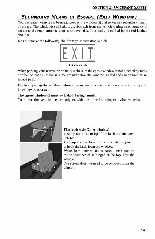
Exit Window Label
Secondary Means of Escape (Exit Window)Your recreation vehicle has been equipped with a window(s) that serves as a secondary means of escape. The window(s) will allow a quick exit from the vehicle during an emergency if access to the main entrance door is not available. It is easily identified by the red latches and label.
Do not remove the following label from your recreation vehicle:
When parking your recreation vehicle, make sure the egress window is not blocked by trees or other obstacles. Make sure the ground below the window is solid and can be used as an escape path.
Practice opening the window before an emergency occurs, and make sure all occupants know how to operate it:
The egress window(s) must be locked during transit.Your recreation vehicle may be equipped with one of the following exit window styles.
Flip latch style (2 per window)Push up on the front lip of the latch and the latch unfolds.Push up on the front lip of the latch again to unhook the latch from the window. When both latches are released, push out on the window which is hinged at the top. Exit the vehicle.The screen does not need to be removed from the window.
20
Section 2: Occupant Safety
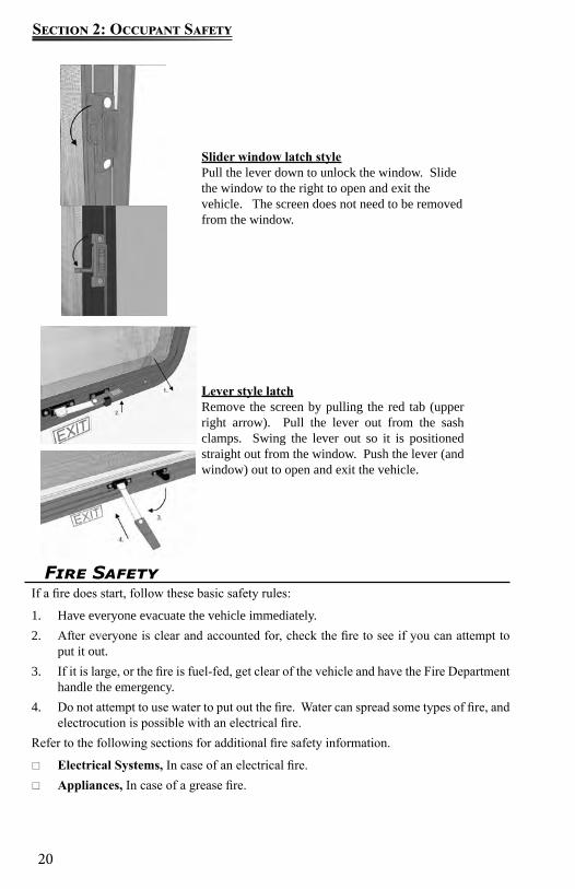
Slider window latch stylePull the lever down to unlock the window. Slidethe window to the right to open and exit the vehicle. The screen does not need to be removedfrom the window.
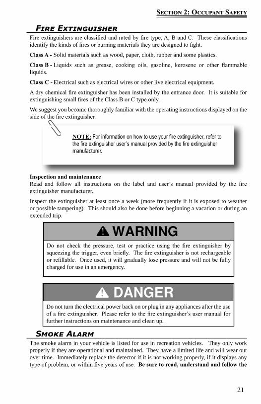
Lever style latchRemove the screen by pulling the red tab (upper right arrow). Pull the lever out from the sash clamps. Swing the lever out so it is positioned straight out from the window. Push the lever (and window) out to open and exit the vehicle.
Fire SafetyIf a fire does start, follow these basic safety rules:
1. Have everyone evacuate the vehicle immediately.2. After everyone is clear and accounted for, check the fire to see if you can attempt to
put it out. 3. If it is large, or the fire is fuel-fed, get clear of the vehicle and have the Fire Department
handle the emergency.4. Do not attempt to use water to put out the fire. Water can spread some types of fire, and
electrocution is possible with an electrical fire.Refer to the following sections for additional fire safety information.
Electrical Systems, In case of an electrical fire. Appliances, In case of a grease fire.
21
Section 2: Occupant Safety
Do not turn the electrical power back on or plug in any appliances after the use of a fire extinguisher. Please refer to the fire extinguisher’s user manual for further instructions on maintenance and clean up.
Do not check the pressure, test or practice using the fire extinguisher by squeezing the trigger, even briefly. The fire extinguisher is not rechargeable or refillable. Once used, it will gradually lose pressure and will not be fully charged for use in an emergency.
NOTE: For information on how to use your fire extinguisher, refer to the fire extinguisher user’s manual provided by the fire extinguisher manufacturer.
Fire ExtinguisherFire extinguishers are classified and rated by fire type, A, B and C. These classifications identify the kinds of fires or burning materials they are designed to fight.
Class A - Solid materials such as wood, paper, cloth, rubber and some plastics.
Class B - Liquids such as grease, cooking oils, gasoline, kerosene or other flammable liquids.
Class C - Electrical such as electrical wires or other live electrical equipment.
A dry chemical fire extinguisher has been installed by the entrance door. It is suitable for extinguishing small fires of the Class B or C type only.
We suggest you become thoroughly familiar with the operating instructions displayed on the side of the fire extinguisher.
Inspection and maintenanceRead and follow all instructions on the label and user’s manual provided by the fire extinguisher manufacturer.
Inspect the extinguisher at least once a week (more frequently if it is exposed to weather or possible tampering). This should also be done before beginning a vacation or during an extended trip.
Smoke AlarmThe smoke alarm in your vehicle is listed for use in recreation vehicles. They only work properly if they are operational and maintained. They have a limited life and will wear out over time. Immediately replace the detector if it is not working properly, if it displays any type of problem, or within five years of use. Be sure to read, understand and follow the
22
Section 2: Occupant Safety
information provided by the smoke alarm manufacturer, including information on the limited life of smoke alarms.
Be aware the smoke alarm is not fool proof and cannot detect fires if smoke does not reach it. Anything preventing smoke from reaching the alarm may delay or prevent an alarm.
Though the alarm horn in this detector meets or exceeds current UL standards, it may not be heard for reasons that include (but not limited to): a closed or partially closed door, other noise from electronics, appliances or traffic.
The smoke alarm is operational once the battery is correctly installed. It will not function if the battery is missing, disconnected, dead, the wrong type or not installed correctly. It requires one standard 9V battery. Refer to the user’s guide, for correct battery and installation information,
The LED light will indicate the battery is functioning properly. When the production of combustion is sensed, the smoke detector sounds a loud alarm that continues until the air is cleared. The LED light will also give a visual indication of a sounding alarm.
When the battery becomes weak, the alarm will “beep” about once a minute indicating a low battery. This warning should last for 30 days. You MUST replace the battery once the alarms low battery warning (beeping) starts to assure continued protection.
When the battery is removed from the alarm, the battery flag will pop up; the alarm cannot be installed to the mounting bracket without a battery.
To test, stand at arm’s length from the smoke alarm as the alarm horn is loud and may be harmful to your hearing. The test button will accurately test all functions. Never use an open flame to test the smoke alarm.
Test the smoke alarm operation after the vehicle has been in storage, before each trip and at least once per week during use. Do not disconnect the battery or the alarm.
This smoke alarm will not alert hearing impaired residents. Special alarms with flashing strobe lights are recommended for the hearing impaired
Only use the replacement battery recommended by the smoke detector manufacturer. The smoke detector alarm may not operate properly with other batteries. Never use a rechargeable battery as it may not provide a constant charge. Never disconnect the battery to silence the alarm.
23
Section 2: Occupant Safety
Do not remove the warning label located near the smoke alarm from your recreation vehicle:
MaintenanceVacuum off any dust on the cover of the smoke alarm using a soft brush attachment. Test the smoke alarm once you have vacuumed. Never use water, cleaners or solvents to clean the smoke alarm as they may damage the alarm. Do not paint the smoke alarm. Refer to the manufacturer’s use guide for detailed maintenance information.
Smoke detector warning label
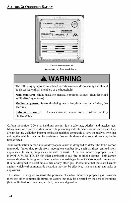
Combination Carbon Monoxide/ Propane Alarm
Your recreation vehicle is equipped with a combination carbon monoxide (CO)/propane alarm that is listed for use in recreation vehicles. The combination carbon monoxide/ propane alarm will only work if it is operational and maintained.
The alarm is wired directly to the 12-volt electrical system, with continuous power being supplied by the recreation vehicle battery. There is no 9-volt battery power supply in the carbon monoxide/propane alarm. If the battery cable is disconnected at the battery terminals, the combination alarm will not work.
Be sure to read, understand and follow the owner’s information from the manufacturer of the combination CO/propane alarm supplied in your Warranty Packet. This includes information regarding the limited life of the alarm.
The carbon monoxide detector installed is intended for use in ordinary indoor locations of recreation vehicles. It is not designed to comply with Occupational Safety and Health Administration (OSHA) commercial or industrial standards.
Do not disconnect the battery or the alarm.
Individuals with medical problems may consider using warning devices that provide audible and visual signals for carbon monoxide concentrations under 30 PPM.
This alarm will only indicate the presence of carbon monoxide gas at the sensor. Carbon monoxide gas may be present in other areas.
The ultimate responsibility for protection against toxic carbon monoxide fumes rests solely on you. Installing a carbon monoxide/propane alarm is just the first step in protecting your family from toxic carbon monoxide poisoning
24
Section 2: Occupant Safety
Carbon monoxide (CO) is an insidious poison. It is a colorless, odorless and tasteless gas. Many cases of reported carbon monoxide poisoning indicate while victims are aware they are not feeling well, they become so disoriented they are unable to save themselves by either exiting the vehicle or calling for assistance. Young children and household pets may be the first affected.
Your combination carbon monoxide/propane alarm is designed to detect the toxic carbon monoxide fumes that result from incomplete combustion, such as those emitted from appliances, furnaces, fireplaces and auto exhaust. A carbon monoxide/propane alarm is NOT A SUBSTITUTE for other combustible gas, fire or smoke alarms. This carbon monoxide alarm is designed to detect carbon monoxide gas from ANY source of combustion. It is not designed to detect smoke, fire or any other gas. Please note that there are hazards against which carbon monoxide detection may not be effective, such as natural gas leaks or explosions.
This alarm is designed to sense the presence of carbon monoxide/propane gas, however there are other combustible fumes or vapors that may be detected by the sensor including (but not limited to ): acetone, alcohol, butane and gasoline.
The following symptoms are related to carbon monoxide poisoning and should be discussed with all members of the household:
Mild exposure: Slight headache, nausea, vomiting, fatigue (often described as “flu-like” symptoms).
Medium exposure: Severe throbbing headaches, drowsiness, confusion, fast heart rate.
Extreme exposure: Unconsciousness, convulsions, cardio-respiratory failure, death.
LP/Carbon monoxide detector
(alarm may vary from model shown)
25
Section 2: Occupant Safety
These chemicals can be found in commonly used items such as deodorants, colognes, perfumes, adhesives, lacquer, kerosene, glues, wine, liquor, most cleaning agents and the propellants of aerosol cans.
High temperatures can activate glue and adhesive vapors. If you close up the recreation vehicle on a hot day, the chemicals used in its construction may be detected for months after the vehicle was constructed (for more information, refer to Section 2, Formaldehyde).
What you should do if the alarm sounds
1. Operate the RESET/SILENCE button.2. Call your emergency services (fire department or 911).3. Immediately move to fresh air (outdoors or by an open door or window)4. Do not re-enter the premises or move away from the open door or window until the
emergency service responders have arrived, the premises have been aired out, and your alarm remains in its normal condition.
If your alarm reactivates within a 24-hour period, repeat steps 1-4 and call a qualified appliance technician to investigate for sources of carbon monoxide from fuel burning equipment and appliances, and inspect for proper operation of this equipment. Make sure that motor vehicle(s) are not, and have not been, operating in an attached garage or adjacent to the recreation vehicle.
If problems are identified during this inspection, have the alarm serviced immediately. Note any combustion equipment not inspected by the technician and consult the manufacturer’s instructions or contact the manufacturer directly for more information about carbon monoxide safety and this alarm.
Alarm Signals Normal Operation: The LED will maintain a steady green light, indicating that the
alarm is powered. CO alarm condition: The red LED light will remain steady and the alarm will sound 4
“BEEPS” then silent for 5 seconds. These signals indicate immediate action is required. Propane gas alarm: The red LED light will flash and the alarm will sound a steady
Actuation of this detector indicates the presence of carbon monoxide which can kill you.
Never turn the 12-volt battery disconnect control to the off position and disconnect the battery cable to silence an alarm. The alarm will automatically sense when the level of carbon monoxide in the air reaches below dangerous levels. You should stay outside the vehicle in fresh air until the alarm is silenced. When the alarm sounds, do not stand too close to the alarm. The sound produced by the alarm is loud because it is designed to wake a person in an emergency. Prolonged exposure to the alarm at a close distance may be harmful to your hearing.:
26
Section 2: Occupant Safety
tone. These signals indicate immediate action is required. Alarm malfunction/low battery: The gas LED will remain off and the Operational/
CO LED will alternate re/green and the alarm will sound once every 15 seconds.
End of life alarm: The LED will flash red/red, green/green and the alarm will “BEEP every 25-30 seconds. The alarm should be immediately replaced.
MaintenanceVacuum the alarm cover at least once a year. Clean the cover by hand using a cloth dampened in clean water. Dry with a soft cloth. Do not spray the front panel of the alarm with cleaning agents or waxes. This action may damage the sensor causing an alarm or cause the alarm to malfunction. Do not paint the face of the alarm.
Testing the combination carbon monoxide/ propane alarm
The TEST/RESET button tests all ELECTRICAL functions of the alarm. The TEST/Mute switch is located on the front of the alarm. Press and hold the test button for 1 second. The alarm is working properly if the GREEN indicator light changes color to RED and the horn beeps 4 times. The Gas LED should also blink red.
Repair or replace the combination carbon monoxide/propane alarm when the alarm no longer functions. As with any electronic product, it has a limited life. Alarms that do not work cannot protect you.
Refer to the Warranty Packet for more information from the carbon monoxide/ propane alarm manufacturer.
NOTE: The carbon monoxide/propane alarm manufacturer strongly recommends replacement of the detector five years after the date of purchase.
NOTE: Pressing the test button does not check the sensor opera-tion. Refer to the carbon monoxide/propane alarm manufacturers user’s manual provided in the Warranty Packet for additional informa-tion on testing the sensors.
Test the alarm operation after the RV has been in storage, before each trip and at least once per week during use.
27
Section 2: Occupant Safety
FormaldehydeSome components in the recreation vehicle contain formaldehyde-based adhesives that may release formaldehyde fumes into the air for an unknown period of time. Individuals who are allergic to formaldehyde gas fumes may experience irritation to eyes, ears, nose and throat. Indoor air quality may also be affected by leaving your vehicle closed for a period of time.
To aid in dissipation, ventilate the recreation vehicle by opening all windows and circulate the air with a fan.
This label is located inside the vehicle near the entry door. The label should be left permanently affixed to the recreation vehicle:
Extended Or Full Time UsageYour new recreation vehicle has been built for enjoyment in a recreational manner. It is not intended for use as full-time quarters or a permanent residence. Continuous living in your vehicle could cause accelerated wear and damage to the various components.
Continuous or permanent living in your recreation vehicle may affect your warranty coverage and may void the “Limited Warranty” applicable to your vehicle.
Cold Weather UsageWhen used in freezing or below freezing temperatures, the precautions should be taken:
Fresh water and drainage systems - preparations to avoid freeze-ups. Propane gas (if so equipped) and sufficient power is needed for protection from possible
freeze-ups on the propane gas regulator. Keep in mind that more frequent furnace operation will substantially increase battery draw and propane gas use.
During cool weather usage, ventilation or addition of a dehumidifier may be required to reduce condensation.
Check outside extrusions on compartment doors, locks, slide outs, windows, vents, etc., for frozen moisture before operating to avoid damage to parts.
CondensationCondensation is a natural phenomenon. The amount of condensation will vary with climate conditions, particularly the relative humidity. Condensation occurs because there is water vapor present in the air. When the temperature reaches the “dew point” the water vapor in the air condenses and changes to a liquid form.
Proper ventilation or the use of a dehumidifier (customer supplied) will assist in controlling the condensation. Suggestions to eliminate warm moist air:
Crack open windows and roof vents to allow warm moist air to escape. Open the bath roof vent (if so equipped) approximately ½” when showering. Use the range hood fan (if so equipped) when cooking or washing dishes.
28
Section 2: Occupant Safety
Condensation may cause dampness, mildew, mold, staining and, if allowed to continue, it may result in damage to the recreation vehicle (damage caused by condensation is not warrantable). It can also lead to mold or mildew issues, which could be a health hazard.
Avoid hanging wet towels (or clothes) inside the recreation vehicle to dry. If found in cabinets or closets, open the doors slightly to provide ventilation.
29
Section 3: Pre-travel information
The factory-installed weight labels are specific to the recreation vehicle for which they are supplied and are not interchangeable. Do not remove these labels from your vehicle. If labels are missing contact your dealer or Customer Service for replacements.
Vehicle LabelsDecals and data plates used throughout the motor home aid in its safe and efficient operation; others give service instructions. Read all decals, data and instruction plates before operating your recreation vehicle. Any decal, data or instruction plate painted over, damaged or removed should be replaced.
Keep a record of the 17-digit chassis vehicle identification number (VIN), the 9-digit serial number, and your license number in the event theft or vandalism requires you to supply this information to the authorities.
Weight TermsGAWR - Gross Axle Weight Rating: The value specified by the vehicle manufacturer as the load-carrying capacity of a single axle system, as measured at the tire-to-ground interfaces. This is the total weight a given axle is capable of carrying.
GCWR - Gross Combined Weight Rating: The value specified by the motor home manufacturer as the maximum allowable loaded weight of the motor home in combination with its towed trailer or towed vehicle. The tongue weight of a towed vehicle/ trailer counts as part of the motor home cargo.
GVWR - Gross Vehicle Weight Rating: The value specified by the manufacturer as the maximum permissible weight of the fully loaded motor home.
OCCC - Occupant And Cargo Carrying Capacity: Is equal to the GVWR of the motor home, minus the weight of the motor home, as completed at the factory, minus the weight of all occupants, including the driver, minus the weight of all personal cargo, minus the weight of a full tank of chassis engine fuel and, if applicable, minus the weight of a full tank of propane. The full weight of potable water, including the water heater and the tongue weight of a towed vehicle/ trailer counts as cargo in or on the motor home. Additions to or other changes made to the motor home after it left the factory will affect (reduce) the OCCC.
UVW - Unloaded Vehicle Weight: The weight of this motor home as manufactured at the factory with fuel, engine oil and coolants and if applicable, the weight of a full tank of propane.
Do not exceed any applicable motor home weight ratings. Doing so could damage your motor home or affect handling and braking characteristics.
Your motor home braking system is designed and rated for operation at GVWR not GCWR.
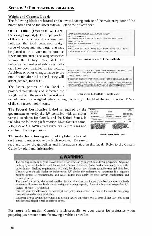
30
Section 3: Pre-travel information
Weight and Capacity LabelsThe following labels are located on the inward-facing surface of the main entry door of the motor home and on the lower sidewall left of the driver’s seat.
OCCC Label (Occupant & Cargo Carrying Capacity): The upper portion of this label is the federally required and indicates the total combined weight value of occupants and cargo that may be placed in or on your motor home as it was manufactured and weighed before leaving the factory. This label also indicates the number of safety seat belts that have been installed at the factory. Additions or other changes made to the motor home after it left the factory will affect (reduce) the OCCC.
The lower portion of the label is provided voluntarily and indicates the weight value of the motor home as it was manufactured and weighed before leaving the factory. This label also indicates the GCWR of the completed motor home.
The Federal Certification Label is required by the government to verify the RV complies with all motor vehicle standards for Canada and the United States. It includes the following information: Manufacturer name, VIN, GVWR, GAWR (front/rear), tire & rim sizes and cold tire inflation pressures.
The motor home towing and braking label is located on the rear bumper above the hitch receiver. Be sure to read and follow the guidelines and information stated on this label. Refer to the Chassis Guide for additional information
For more information Consult a hitch specialist or your dealer for assistance when preparing your motor home for towing a vehicle or trailer.
Lower section Federal OCCC weight labels
Federal Certification Label
Upper section Federal OCCC weight labels

31
Section 3: Pre-travel information
Loading Your Motorhome
When loading heavy objects keep them as low as possible, preferably on the floor.When loading heavy objects keep them as low as possible, preferably on the floor. Distribute cargo side-to-side so the weight on each tire does not exceed one half of the GAWR for either axle. Store and secure all loose items inside the motor home before traveling. Overlooked items such as canned goods, small appliances on the countertop, cooking pans on the range or free-standing furniture items can become dangerous projectiles during a sudden stop.
Never load the motor home in excess of the GVWR or the GAWR for either axle. Overloading your motor home may result in adverse handling characteristics and damage to the chassis.
For traveling safety, it is important to make sure the tie down straps are secured on all appliances such as the toaster, coffee maker, etc. Vibration during travel will move the appliances, creating the potential for them to fall out of their cabinets possibly causing injury.
The actual weight of the vehicle, passengers, all options, liquids, the hitch weight of your towed vehicle and your personal cargo is important for you to know so you do not exceed the Gross Vehicle Weight Rating (GVWR) of the motor home. The volume of space available for storage may exceed the amount of available cargo capacity. Large storage compartments have been designed to accommodate normal camping items, which are bulky, but not necessarily heavy.
Store items in areas designated for storage. Do not store anything in the areas reserved for the converter, electrical panels, furnace or water heater, etc.
Your recreation vehicle’s load capacity is designated by weight, not by volume, so you cannot necessarily use all available space when loading the vehicle. Do not exceed your GVWR and ensure you are loading the vehicle as evenly as you can for the best possible handling. Ensure heavy items are secured so they do not shift during travel.
32
Section 3: Pre-travel information
Trailer PlugIf you choose to tow behind your RV, a chassis manufacturer supplied 7-way trailer plug (located at the hitch) is pre-wired into your motor home. Wiring to operate your towed vehicle brakes must be the same size in both the towed vehicle and the motor home.
White 1 GroundBlue 2 BrakesGreen 3 Running lightsBlack 4 House batteries charge lineRed 5 Stop & left turnBrown 6 Stop & right turnYellow 7 Back up
MaintenanceThe connector plug may build up corrosion with extended use and should be cleaned periodically to insure good electrical contact. Make sure the connector plug is kept clean and protected from road elements as you travel.
7-way trailer plugCar end, rear view
Weighing Your Motor homeNow that your motor home is loaded you should have it weighed. The actual weight of the motor home, passengers, all options, liquids, the hitch weight of your towed vehicle and your personal cargo is important for you to know so you do not exceed the GVWR. There are two important factors when loading your motor home, total weight and balance.
It is imperative that you verify compliance within all applicable weight ratings. Overloading your motor home will void the Limited Warranty and the warranties of many component part manufacturers.
Have your RV weighed periodically at a public scale to determine the proper load distribution. Keep in mind that individual scales will operate differently. The surroundings of the scale need to be adequate to accommodate weighing each side of your motor home.
There are three basic types of public scales. Each type of scale involves a different procedure in weighing the motor home. Your motor home must remain as level as possible on the scale (even if an axle is not physically on the scale). To obtain the side-to-side weights, make sure there is enough space on either side of the scale to accommodate the motor home being partially off the scale.
DO NOT EXCEED YOUR GVWR! This means you should weigh your vehicle as loaded for your normal travel to determine the actual weight.
If you exceed the GVWR, you MUST remove items from the motor home, or drain liquids, then re-weigh the vehicle to ensure you have achieved a safe weight. Weight labels are posted inside a cabinet door inside all motor homes so you can make a decision before you buy about how much cargo capacity is important for you personally.
33
Section 3: Pre-travel information
If a boat, trailer or other vehicle is being towed, it should be weighed separately. This weight should be combined with the motor home’s Gross Vehicle Weight (GVW) to ensure the total combined weight does not exceed the GCWR.
Once actual weights are obtained, it is now possible to compare them to the Weight Information Label weight ratings to ensure you are below the posted minimum ratings.
If there is a difference in the weights on one side of the vehicle as compared to weights on the other side, components (tires, wheels, brakes, springs, etc.) on the heavier side may be overloaded, although the total axle load is within the GAWR.See Vehicle Labels and Loading Your Motor home, for important information on how towing a vehicle affects the motor home weight.
Dump the gray and black water holding tanks before traveling to avoid carrying unnecessary weight. Traveling with the tanks full can affect your fuel consumption, and depending on the location of the tanks, can affect your vehicle handling characteristics. If you are dry camping and cannot immediately empty your holding tanks, reduce your vehicle speed until you reach a dumping station.
It is important to redistribute the load to avoid component failure as well as to improve the handling characteristics of the vehicle.

34
Section 3: Pre-travel information
Notes:
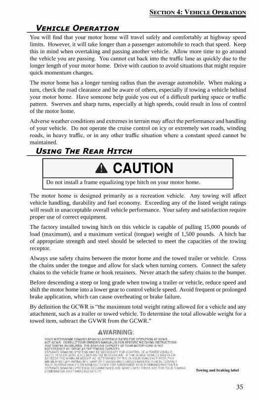
35
Section 4: Vehicle Operation
Vehicle OperationYou will find that your motor home will travel safely and comfortably at highway speed limits. However, it will take longer than a passenger automobile to reach that speed. Keep this in mind when overtaking and passing another vehicle. Allow more time to go around the vehicle you are passing. You cannot cut back into the traffic lane as quickly due to the longer length of your motor home. Drive with caution to avoid situations that might require quick momentum changes.
The motor home has a longer turning radius than the average automobile. When making a turn, check the road clearance and be aware of others, especially if towing a vehicle behind your motor home. Have someone help guide you out of a difficult parking space or traffic pattern. Swerves and sharp turns, especially at high speeds, could result in loss of control of the motor home.
Adverse weather conditions and extremes in terrain may affect the performance and handling of your vehicle. Do not operate the cruise control on icy or extremely wet roads, winding roads, in heavy traffic, or in any other traffic situation where a constant speed cannot be maintained.
Using The Rear Hitch
The motor home is designed primarily as a recreation vehicle. Any towing will affect vehicle handling, durability and fuel economy. Exceeding any of the listed weight ratings will result in unacceptable overall vehicle performance. Your safety and satisfaction require proper use of correct equipment.
The factory installed towing hitch on this vehicle is capable of pulling 15,000 pounds of load (maximum), and a maximum vertical (tongue) weight of 1,500 pounds. A hitch bar of appropriate strength and steel should be selected to meet the capacities of the towing receptor.
Always use safety chains between the motor home and the towed trailer or vehicle. Cross the chains under the tongue and allow for slack when turning corners. Connect the safety chains to the vehicle frame or hook retainers. Never attach the safety chains to the bumper.
Before descending a steep or long grade when towing a trailer or vehicle, reduce speed and shift the motor home into a lower gear to control vehicle speed. Avoid frequent or prolonged brake application, which can cause overheating or brake failure.
By definition the GCWR is “the maximum total weight rating allowed for a vehicle and any attachment, such as a trailer or towed vehicle. To determine the total allowable weight for a towed item, subtract the GVWR from the GCWR.”
Do not install a frame equalizing type hitch on your motor home.
Towing and braking label

36
Section 4: Vehicle Operation
Total weight of your motor home and any trailer or vehicle towed by it must not exceed the GCWR. Do not assume that you can tow a RV that happens to be within the capacity of the tow vehicle hitch. By doing so, you may exceed the total GCWR of the motor home.
The total weight of your motor home (including cargo, passengers, fluids, etc.) in addition to the vertical (tongue) weight must not exceed the GVWR and/or any GAWR. Once again, do not assume that you can tow a trailer or vehicle that happens to be within the vertical (tongue) weight capacity of the hitch. By doing so, you may exceed the GVWR and/or GAWR of the motor home
Your motor home chassis breaking system is rated for operation at GVWR, NOT GCWR. Any trailer or vehicle being towed by your motor home must have adequate brakes as required by all state (or province) and local regulations for towing with your motor home, including areas you may be traveling through.
In addition, a separate supplemental braking system must be installed if the towed trailer or vehicle meets or exceeds the minimum weight determined by the chassis manufacturer (this minimum weight rating will vary by chassis and chassis manufacturer).
Contact your dealer for assistance in determining whether a separate braking system is recommended for your towing and traveling safety. Failure to follow these instructions will create a safety hazard and may result in an accident.
MaintenanceKeep the hitch clean along with your general frame maintenance.
At the beginning of the season, and monthly or thereafter, clean the inside of the receiver tube with a wire brush and spray with a silicone spray.
Always remove the utility mount from the receiver when it is not in use. This will help prevent the utility mount from rusting to the tube.
Periodically check the bolts for tightness. They need to be torqued to the proper setting (refer to your Chassis Guide).
Refer to the Electrical Systems section for information on the trailer plug.
Braking & StoppingEven though your motor home is equipped with brakes designed for its Gross Vehicle Weight Rating (GVWR) we suggest you practice stopping away from traffic until you become accustomed to your motor home’s stopping distance. Your motor home is equipped with a
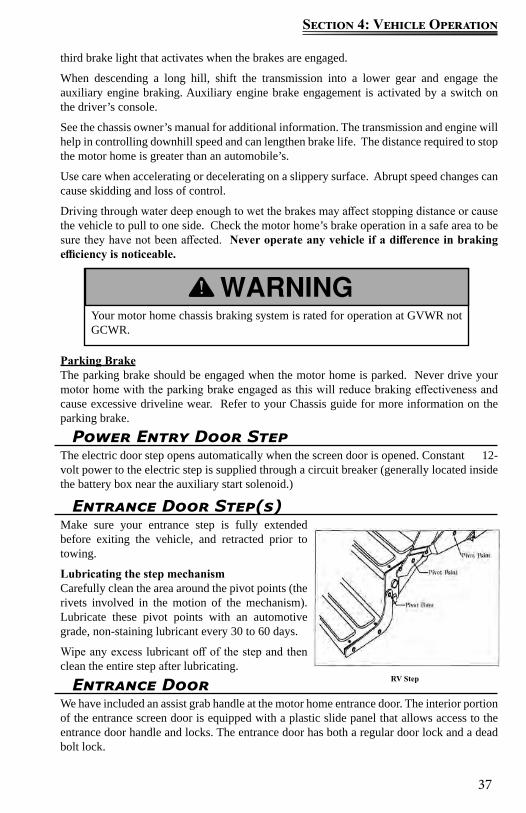
37
Section 4: Vehicle Operation
Your motor home chassis braking system is rated for operation at GVWR not GCWR.
Power Entry Door StepThe electric door step opens automatically when the screen door is opened. Constant 12-volt power to the electric step is supplied through a circuit breaker (generally located inside the battery box near the auxiliary start solenoid.)
Entrance Door Step(s)Make sure your entrance step is fully extended before exiting the vehicle, and retracted prior to towing.
Lubricating the step mechanismCarefully clean the area around the pivot points (the rivets involved in the motion of the mechanism). Lubricate these pivot points with an automotive grade, non-staining lubricant every 30 to 60 days.
Wipe any excess lubricant off of the step and then clean the entire step after lubricating.
third brake light that activates when the brakes are engaged.
When descending a long hill, shift the transmission into a lower gear and engage the auxiliary engine braking. Auxiliary engine brake engagement is activated by a switch on the driver’s console.
See the chassis owner’s manual for additional information. The transmission and engine will help in controlling downhill speed and can lengthen brake life. The distance required to stop the motor home is greater than an automobile’s.
Use care when accelerating or decelerating on a slippery surface. Abrupt speed changes can cause skidding and loss of control.
Driving through water deep enough to wet the brakes may affect stopping distance or cause the vehicle to pull to one side. Check the motor home’s brake operation in a safe area to be sure they have not been affected. Never operate any vehicle if a difference in braking efficiency is noticeable.
Parking BrakeThe parking brake should be engaged when the motor home is parked. Never drive your motor home with the parking brake engaged as this will reduce braking effectiveness and cause excessive driveline wear. Refer to your Chassis guide for more information on the parking brake.
RV StepEntrance DoorWe have included an assist grab handle at the motor home entrance door. The interior portion of the entrance screen door is equipped with a plastic slide panel that allows access to the entrance door handle and locks. The entrance door has both a regular door lock and a dead bolt lock.
38
Section 4: Vehicle Operation
NOTE: Locks on entrance and baggage doors need biannual lubri-cation using a light coat of silicone spray. Conditions such as rain, salt, dust and pollution may increase the maintenance needs.
KeysSeveral keys are provided when you purchase your vehicle. Most keys have an individual key number stamped on the plate. Record these key numbers and keep the information in a safe place. You can order a key blank from your dealer to have duplicate keys made. If you lose the keys, contact your dealer or a locksmith for assistance. Make sure the keys are not inside the vehicle before you close and lock the entrance door.
Keyless Entry (if so equipped)If your RV is equipped with a keyless entry system, it is a battery operated system. Programming and changing batteries on the lock system are described in the following sections.
For detailed instructions, please refer to the manufacturer’s operators manual included in your warranty packet.
Battery powered keyless entry system:The battery powered entry system is a 4 button touch pad programmable deadbolt lock. The 4 buttons are labeled “1|2”, “3|4”, “5|6”, “7|8”. The button labeled “1|2” is the same button whether the number 1 or 2 is desired. Please note this handle uses touch technology. The buttons are activated by touch and do not require pressing the buttons. Touch the button and lift finger from button for proper code entry.
Operation The entry system incorporates proximity sensing to determine when you want to activate the lock. To operate the lock you first must “wake up” the lock, by touching the “wake up area” to the right of the buttons. The buttons will illuminate once the Touch Pad is wakened. This indicates that the touch pad is ready for the code to be entered. (Refer to the diagram on next page)
Preset Factory Code The entry system has a factory set code of 3,7,1,5 followed by the Enter button. The Enter button is the bottom button with the picture of the key. The Enter button is required to be touched after the code is entered. The factory code resets every time the batteries are removed for at least 10 seconds.
Always hold onto the entry door when opening or closing it. Damage caused by the entry door catch and holder because you failed to do so is not covered by the Motorized Limited Warranty.
Make sure the entrance door is completely closed and locked when traveling. Locking the door helps prevent it from opening unintentionally and keeps intruders from your motor home.
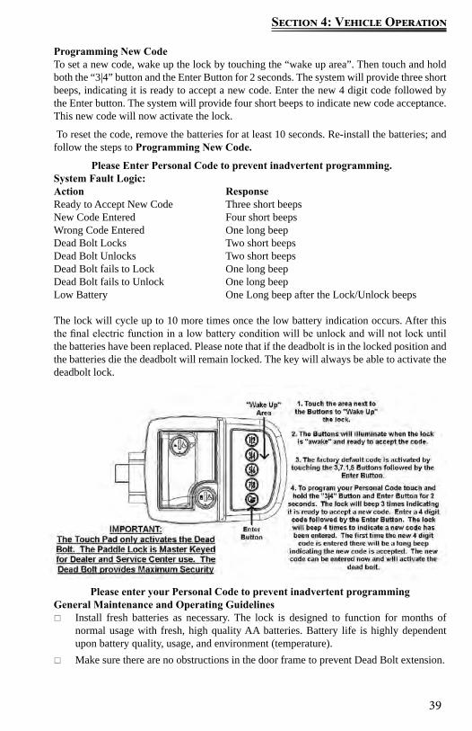
39
Section 4: Vehicle Operation
Programming New Code To set a new code, wake up the lock by touching the “wake up area”. Then touch and hold both the “3|4” button and the Enter Button for 2 seconds. The system will provide three short beeps, indicating it is ready to accept a new code. Enter the new 4 digit code followed by the Enter button. The system will provide four short beeps to indicate new code acceptance. This new code will now activate the lock.
To reset the code, remove the batteries for at least 10 seconds. Re-install the batteries; and follow the steps to Programming New Code.
Please Enter Personal Code to prevent inadvertent programming. System Fault Logic:Action Response Ready to Accept New Code Three short beeps New Code Entered Four short beeps Wrong Code Entered One long beep Dead Bolt Locks Two short beeps Dead Bolt Unlocks Two short beeps Dead Bolt fails to Lock One long beep Dead Bolt fails to Unlock One long beep Low Battery One Long beep after the Lock/Unlock beeps
The lock will cycle up to 10 more times once the low battery indication occurs. After this the final electric function in a low battery condition will be unlock and will not lock until the batteries have been replaced. Please note that if the deadbolt is in the locked position and the batteries die the deadbolt will remain locked. The key will always be able to activate the deadbolt lock.
Please enter your Personal Code to prevent inadvertent programmingGeneral Maintenance and Operating Guidelines
Install fresh batteries as necessary. The lock is designed to function for months of normal usage with fresh, high quality AA batteries. Battery life is highly dependent upon battery quality, usage, and environment (temperature).
Make sure there are no obstructions in the door frame to prevent Dead Bolt extension.
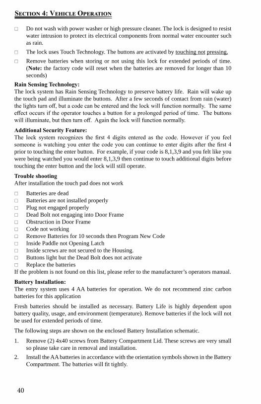
40
Section 4: Vehicle Operation
Do not wash with power washer or high pressure cleaner. The lock is designed to resist water intrusion to protect its electrical components from normal water encounter such as rain.
The lock uses Touch Technology. The buttons are activated by touching not pressing. Remove batteries when storing or not using this lock for extended periods of time.
(Note: the factory code will reset when the batteries are removed for longer than 10 seconds)
Rain Sensing Technology:The lock system has Rain Sensing Technology to preserve battery life. Rain will wake up the touch pad and illuminate the buttons. After a few seconds of contact from rain (water) the lights turn off, but a code can be entered and the lock will function normally. The same effect occurs if the operator touches a button for a prolonged period of time. The buttons will illuminate, but then turn off. Again the lock will function normally.
Additional Security Feature:The lock system recognizes the first 4 digits entered as the code. However if you feel someone is watching you enter the code you can continue to enter digits after the first 4 prior to touching the enter button. For example, if your code is 8,1,3,9 and you felt like you were being watched you would enter 8,1,3,9 then continue to touch additional digits before touching the enter button and the lock will still operate.
Trouble shootingAfter installation the touch pad does not work
Batteries are dead Batteries are not installed properly Plug not engaged properly Dead Bolt not engaging into Door Frame Obstruction in Door Frame Code not working Remove Batteries for 10 seconds then Program New Code Inside Paddle not Opening Latch Inside screws are not secured to the Housing. Buttons light but the Dead Bolt does not activate Replace the batteries
If the problem is not found on this list, please refer to the manufacturer’s operators manual.
Battery Installation: The entry system uses 4 AA batteries for operation. We do not recommend zinc carbon batteries for this application
Fresh batteries should be installed as necessary. Battery Life is highly dependent upon battery quality, usage, and environment (temperature). Remove batteries if the lock will not be used for extended periods of time.
The following steps are shown on the enclosed Battery Installation schematic.
1. Remove (2) 4x40 screws from Battery Compartment Lid. These screws are very small so please take care in removal and installation.
2. Install the AA batteries in accordance with the orientation symbols shown in the Battery Compartment. The batteries will fit tightly.
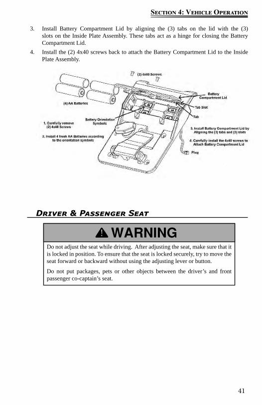
41
Section 4: Vehicle Operation
Do not adjust the seat while driving. After adjusting the seat, make sure that it is locked in position. To ensure that the seat is locked securely, try to move the seat forward or backward without using the adjusting lever or button.
Do not put packages, pets or other objects between the driver’s and front passenger co-captain’s seat.
Driver & Passenger Seat
3. Install Battery Compartment Lid by aligning the (3) tabs on the lid with the (3) slots on the Inside Plate Assembly. These tabs act as a hinge for closing the Battery Compartment Lid.
4. Install the (2) 4x40 screws back to attach the Battery Compartment Lid to the Inside Plate Assembly.
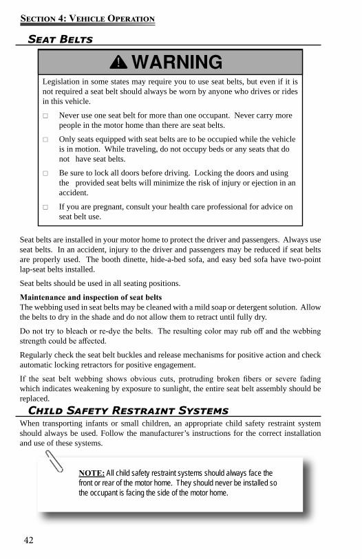
42
Section 4: Vehicle Operation
Seat Belts
Seat belts are installed in your motor home to protect the driver and passengers. Always use seat belts. In an accident, injury to the driver and passengers may be reduced if seat belts are properly used. The booth dinette, hide-a-bed sofa, and easy bed sofa have two-point lap-seat belts installed.
Seat belts should be used in all seating positions.
Maintenance and inspection of seat beltsThe webbing used in seat belts may be cleaned with a mild soap or detergent solution. Allow the belts to dry in the shade and do not allow them to retract until fully dry.
Do not try to bleach or re-dye the belts. The resulting color may rub off and the webbing strength could be affected.
Regularly check the seat belt buckles and release mechanisms for positive action and check automatic locking retractors for positive engagement.
If the seat belt webbing shows obvious cuts, protruding broken fibers or severe fading which indicates weakening by exposure to sunlight, the entire seat belt assembly should be replaced.
Legislation in some states may require you to use seat belts, but even if it is not required a seat belt should always be worn by anyone who drives or rides in this vehicle.
Never use one seat belt for more than one occupant. Never carry more people in the motor home than there are seat belts.
Only seats equipped with seat belts are to be occupied while the vehicle is in motion. While traveling, do not occupy beds or any seats that do not have seat belts.
Be sure to lock all doors before driving. Locking the doors and using the provided seat belts will minimize the risk of injury or ejection in an accident.
If you are pregnant, consult your health care professional for advice on seat belt use.
NOTE: All child safety restraint systems should always face the front or rear of the motor home. They should never be installed so the occupant is facing the side of the motor home.
Child Safety Restraint SystemsWhen transporting infants or small children, an appropriate child safety restraint system should always be used. Follow the manufacturer’s instructions for the correct installation and use of these systems.
43
Section 4: Vehicle Operation
Adjust the outside rearview mirrors before driving.
The rear vision camera aids in the use of, but does not replace vehicle side/rear-view mirrors
Outside Rearview Mirrors After adjusting the front driver’s seat, adjust the outside rearview mirrors to your driving preference. Have someone help you adjust the mirrors in the desired direction for maximum rear visibility before driving. During travel, vibration may loosen the fitting holding the mirror(s), causing them to change position. As part of your regular motor home maintenance, check and adjust the mirrors to the desired position.
Power remote mirrors (if so equipped)You can adjust the power remote mirrors when the ignition key is in the ON position.
1. Move the control knob to the side you want to adjust.2. Press the control arrows in the direction you want the mirror to move.3. Return the control knob to the center to lock the mirror(s) into place.The power remote mirrors also contain heating elements to defog or de-ice the mirrored glass if needed. To activate this feature, use the “Mirror Heat” control located on the driver’s side console next to the mirror control.
Rear Vision Camera Your motor home is equipped with a rear vision monitor that gives a limited televised view of what is behind your motor home. The rear vision camera will aid you in backing up the motor home, and can be used for a greater field of vision when driving in heavy traffic.
In addition to the rear vision camera, your RV may be equipped with side view cameras as well. These will be mounted on each side of the RV facing rearward to give you views down each side of the motor home.
Check the outside rear view mirrors when driving and backing up the motor home for a more complete field of vision.
Objects in the camera/monitor view can be closer than they appear. To become accustomed to using the rear view camera monitor, practice backing up in a safe place. If in doubt, ask another person outside the vehicle to assist.
The monitor is operational whenever the engine is running. To use the monitor, flip the switch from standby to ON (the monitor will also work when with the motor home is in “reverse” and the monitor in standby). Make sure you turn the monitor to standby while driving to avoid being distracted.
Never operate the rear vision monitor in the ON position for extended periods of time as this may result in an “image burn” on the monitor.
For detailed operating and safety information, refer to the manufacturers user guide.
44
Section 4: Vehicle Operation
Campsite Hook-Up Refer to Electrical System section before connecting the shore line power cord (when
using full hook-up) OR before starting the generator (if so equipped) or operating the vehicle on 12-volt power when dry camping.
Refer to Fuel & LP System section before using the LP system. Open the LP gas tank valve (if so equipped) slowly. There may be air in the lines and five to thirty seconds of time is needed to bleed air before LP vapor fills the lines.
Refer to Plumbing Systems section before connecting the fresh water supply or turning ON the water pump or water heater.
When using full hook-up, connect the sewer hose to the campsite sewer hook-up.If applicable, start the refrigerator and the cooling or heating system.
Backing UpWhen parking your motor home, pick a location that is level and back in carefully. Check to ensure there are no obstacles in your path and that you have plenty of vehicle clearance. Check for low-hanging tree limbs, posts, large rocks or other obstacles.
Try to choose a parking site that is on the driver’s side, so you can see what the rear of the motor home is doing. With the site on the passenger side, you would be backing into the site on your blind side. When you determine the site conditions are satisfactory, maneuver the motor home into position for backing up into the site space and follow the instructions listed for backing up the motor home in the Chassis Guide.
Objects in the camera view are closer than they appear. When backing up, proceed cautiously and be prepared to stop.
NOTE: Back up the motor home slowly using the outside rearview mirrors, along with the rear and side view cameras, as aides. Have another person outside the motor home assist you until the motor home is parked in the desired position.
NOTE: For extended dry camping, management of all your re-sources is essential. Check your battery levels and conserve battery power, use it sparingly.

45
Section 4: Vehicle Operation
Hydraulic Leveling SystemYour motor home has been equipped with a hydraulic leveling system. Leveling your motor home is important for several reasons:
The water drainage systems are designed with proper slope and must be level for proper operation.
The appliances perform best when level.The following is an overview of the system functions and operation. For detailed operating and safety information, refer to the manufacturer’s user guide provided in the Owner’s Portfolio.
Before operating the systemThe hydraulic leveling jack system should only be operated under the following conditions:
1. The motor home is parked on a reasonably level surface.2. The motor home parking brake is engaged.3. The motor home transmission gear selector is in NEUTRAL.4. The motor home engine is not running.
Before operating the hydraulic leveling system:
Check that potential jack contact locations are clear of obstructions or depressions.
Keep people clear of the motor home prior to turning the leveling system ON and while the leveling system is in operation.
NOTE: All slide-out rooms should be fully extended prior to leveling the motor home; rooms out, jacks down. Raise the jacks before retracting the slide-out rooms.
NOTE: The chassis air bags will automatically begin dumping when the jacks extend in either manual or automatic mode.
Never expose hands or other parts of the body near hydraulic leaks. High-pressure oil leaks may cut and penetrate the skin causing serious injury.
Never lift the motor home wheels off of the ground when leveling the motor home.
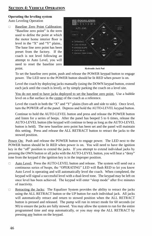
46
Section 4: Vehicle Operation
Operating the leveling systemAuto Leveling Operation
Baseline Zero Point Calibration: “Baseline zero point” is the term used to define the point at which the motor home interior floor is level in the “X” and “Y” plains.. The base line zero point has been preset from the factory. If the coach is not level following an attempt to Auto Level, you will need to reset the baseline zero point. To set the baseline zero point, push and release the POWER keypad button to engage power. The LED next to the POWER button should be lit RED when power is on.
Level the coach by deploying jacks manually (using the DOWN keypad button, extend each jack until the coach is level), or by simply parking the coach on a level site.
You do not need to have jacks deployed to set the baseline zero point. Use a bubble level on a flat surface in the center of the coach as a reference.
Level the coach in both the “X” and “Y” plains (fore-aft and side to side). Once level, turn the POWER off at the panel. Depress and hold the AUTO-LEVEL keypad button.
Continue to hold the AUTO-LEVEL button and press and release the POWER button and listen for a series of beeps. After the panel has beeped 5 to 6 times, release the AUTO-LEVEL button (the keypad will continue to beep as long as the AUTO-LEVEL button is held). The new baseline zero point has been set and the panel will maintain this setting. Press and release the ALL RETRACT button to retract the jacks to the stowed position.
Power On: Push and release the POWER button to engage power. The LED next to the POWER button should be lit RED when power is on. You will need to have the ignition key in the “off” position to extend the jacks. If you attempt to extend individual jacks by pressing the OWN button or all jacks with the AUTO-LEVEL button, you will hear a “deny” tone from the keypad if the ignition key is in the improper position.
Auto Level: Press the AUTO-LEVEL button and release. The system will send out a continuous series of beeps, the “OPERATING” LED will flash RED to let you know Auto Level is operating and will automatically level the coach. When completed, the keypad will signal a successful level with a dual-level tone. The keypad may be left on once level has been achieved. The keypad will enter “sleep mode” after five minutes of inactivity.
Retracting the Jacks: The Equalizer System provides the ability to retract the jacks using the ALL RETRACT button or the UP button for each individual jack. All jacks will automatically retract and return to stowed position when the ALL RETRACT button is pressed and released. The pump will run in retract mode for 60 seconds (or 90) to ensure the jacks are fully stowed. You may allow the system to run for the entire programmed time and stop automatically, or you may stop the ALL RETRACT by pressing any button on the keypad.
Hydraulic Jack Pad
47
Section 4: Vehicle Operation
Manual operationPower on: Push and release the POWER keypad button to engage power. The LED next to the POWER button should be lit RED when power is on. If you attempt to extend individual jacks by pressing the DOWN keypad button or all jacks with the AUTO-LEVEL button, you will hear a “deny” tone from the keypad if the ignition key is in the improper position.
Planting the Jacks: Using the DOWN keypad button, extend each jack until they contact the ground (this is referred to as “planting” the jacks). As you extend the jacks, the LED lights on the keypad will indicate the jacks are out of the “stowed” position. Jacks may be operated individually or in pairs.
Do not manually overextend individual jacks. This may cause unwanted stress on the coach or the jacks.
Leveling the Coach: Use a bubble level in the center of the coach as a reference. Level the vehicle by using DOWN or UP keypad buttons until the vehicle is level. Jacks may be operated individually or in pairs as long as they are operated in the same direction.Do not attempt to lift the vehicle off of the tires. The keypad may be left “on” once level has been achieved. The keypad will enter “sleep mode” after five minutes of inactivity.
Retracting the Jacks: The Equalizer System provides the ability to retract the jacks using the ALL RETRACT button or the UP button for each individual jack. All jacks will automatically retract and return to stowed position when the ALL RETRACT button is pressed and released.
The pump will run in retract mode until all of the jacks are fully stowed (plus an additional 5 seconds) up to a maximum of 60 seconds. You may stop the ALL RETRACT by pressing any button on the keypad. Your coach is equipped with air suspension, and it is recommended that you start your coach before pressing ALL RETRACT allowing the chassis air to build. This will ensure adequate air supply to the chassis air valves.
Helpful Hints The ALL RETRACT function is a timed event. Pressing ALL RETRACT will
cause the pump to run in retract mode for 60 seconds (or 90 seconds, depending on your specific system).
NOTE: There are specific instances when manual extension of one (or more) jack is inhibited (deny tone when DOWN is depressed). This situation is caused by the “anti-twist” protocol in the software contained in the control box. Simply stated, the “anti-twist” protocol denies jack extension if the system senses that a specific corner of the coach is approximately 3 degrees higher than the rest. You will be able to extend other jacks to overcome this slope. If the system incorrectly senses excessive slope, this can be overcome by re-setting the baseline zero point. This will allow manual extension of all jacks. Remember to re-set the baseline zero point after manually leveling the coach.
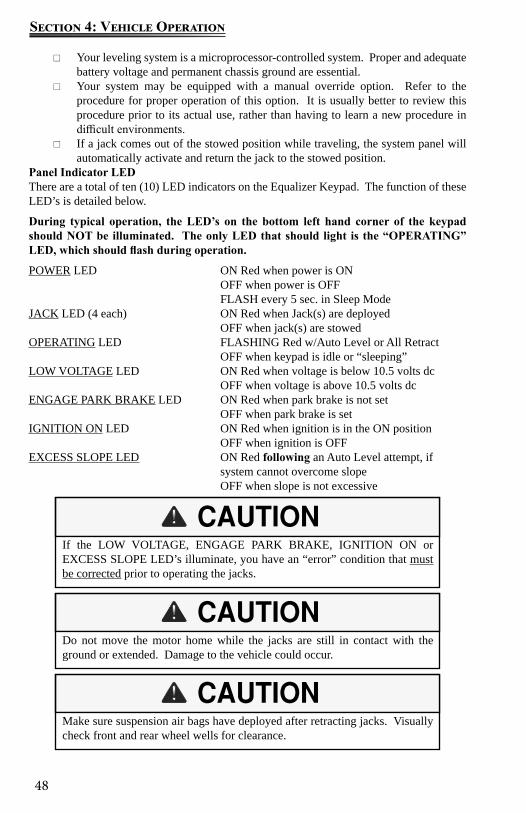
48
Section 4: Vehicle Operation
Your leveling system is a microprocessor-controlled system. Proper and adequate battery voltage and permanent chassis ground are essential.
Your system may be equipped with a manual override option. Refer to the procedure for proper operation of this option. It is usually better to review this procedure prior to its actual use, rather than having to learn a new procedure in difficult environments.
If a jack comes out of the stowed position while traveling, the system panel will automatically activate and return the jack to the stowed position.
Panel Indicator LEDThere are a total of ten (10) LED indicators on the Equalizer Keypad. The function of these LED’s is detailed below.
During typical operation, the LED’s on the bottom left hand corner of the keypad should NOT be illuminated. The only LED that should light is the “OPERATING” LED, which should flash during operation.
POWER LED ON Red when power is ON OFF when power is OFF FLASH every 5 sec. in Sleep ModeJACK LED (4 each) ON Red when Jack(s) are deployed OFF when jack(s) are stowedOPERATING LED FLASHING Red w/Auto Level or All Retract OFF when keypad is idle or “sleeping”LOW VOLTAGE LED ON Red when voltage is below 10.5 volts dc OFF when voltage is above 10.5 volts dcENGAGE PARK BRAKE LED ON Red when park brake is not set OFF when park brake is setIGNITION ON LED ON Red when ignition is in the ON position OFF when ignition is OFFEXCESS SLOPE LED ON Red following an Auto Level attempt, if system cannot overcome slope OFF when slope is not excessive
If the LOW VOLTAGE, ENGAGE PARK BRAKE, IGNITION ON or EXCESS SLOPE LED’s illuminate, you have an “error” condition that must be corrected prior to operating the jacks.
Do not move the motor home while the jacks are still in contact with the ground or extended. Damage to the vehicle could occur.
Make sure suspension air bags have deployed after retracting jacks. Visually check front and rear wheel wells for clearance.
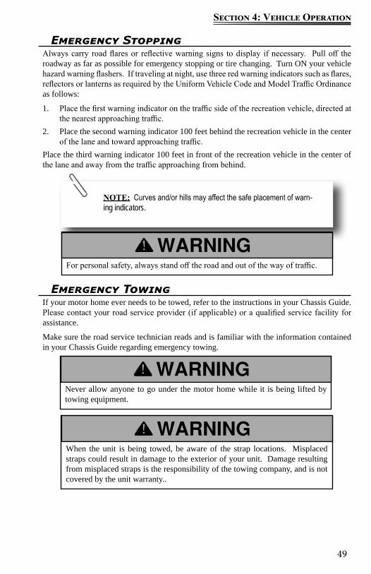
49
Section 4: Vehicle Operation
Emergency StoppingAlways carry road flares or reflective warning signs to display if necessary. Pull off the roadway as far as possible for emergency stopping or tire changing. Turn ON your vehicle hazard warning flashers. If traveling at night, use three red warning indicators such as flares, reflectors or lanterns as required by the Uniform Vehicle Code and Model Traffic Ordinance as follows:
1. Place the first warning indicator on the traffic side of the recreation vehicle, directed at the nearest approaching traffic.
2. Place the second warning indicator 100 feet behind the recreation vehicle in the center of the lane and toward approaching traffic.
Place the third warning indicator 100 feet in front of the recreation vehicle in the center of the lane and away from the traffic approaching from behind.
NOTE: Curves and/or hills may affect the safe placement of warn-ing indicators.
For personal safety, always stand off the road and out of the way of traffic.
Emergency TowingIf your motor home ever needs to be towed, refer to the instructions in your Chassis Guide. Please contact your road service provider (if applicable) or a qualified service facility for assistance.
Make sure the road service technician reads and is familiar with the information contained in your Chassis Guide regarding emergency towing.
Never allow anyone to go under the motor home while it is being lifted by towing equipment.
When the unit is being towed, be aware of the strap locations. Misplaced straps could result in damage to the exterior of your unit. Damage resulting from misplaced straps is the responsibility of the towing company, and is not covered by the unit warranty..

50
Section 4: Vehicle Operation
Front Axle Tire AlignmentThe term alignment refers to both the adjustment angles on the steering axle and suspension and tracking of the rear axle. Many factors are considered when establishing proper alignment. Steering components, suspension, wheel bearings and even proper loading will affect the alignment.
We recommend you have the front suspension and steering alignment checked and adjusted after you have fully loaded the vehicle according to your needs as part of the vehicle maintenance. Thereafter, it is your responsibility to have the alignment inspected periodically to maintain vehicle steering performance and prevent uneven tire wear as part of your normal maintenance.
After this road test has been completed, front-end alignment and/or vibrations will not be covered as part of the new vehicle limited warranty.Follow the Chassis Guide maintenance instructions for the front and rear axle for wheel and suspension maintenance, including the brakes and wheel bearings. Contact your Chassis manufacturer for assistance.
NOTE: Always have the alignment checked and adjusted by a qualified shop with the proper equipment to handle heavy vehicles.
NOTE: A road test by the dealer should be included as part of the pre-delivery inspection. The dealer can check for and correct any steering problems before you take delivery.
Wheel Lug Nuts/Wheel Liners
Torque is the amount of rotating force applied to a fastener, such as a lug nut. Proper torque of lug nuts can only be achieved by using a properly calibrated torque wrench and socket. Do not use a 4-way socket or any other type of wrench that does not measure the actual pressure applied to the lug nut.
After your first trip, check the wheel lug torque periodically for safety according to your Chassis Guide. If you suspect the wheel lug nuts have loosened at any time, have them checked and torqued to the proper limits immediately.
Check and tighten the wheel lug nuts regularly to make sure they did not loosen during travel. Refer to your Chassis Guide for Torque recommendations. Failure to tighten and maintain wheel lug nuts to the proper torque specification, could allow the wheels to come off while the motor home is in motion, and could result in serious injury in the event of a collision or loss of vehicle control.
51
Section 4: Vehicle Operation
Check and re-torque after the first 10, 25 and 50 miles (16, 40 and 80 kilometers). Thereafter, check and maintain the torque according to the listed torque values.
Wheel lugsIf you suspect or notice the wheel stud bolts are cracked or broken, they must be replaced, along with adjacent bolts that have probably also been weakened due to the additional stress placed on them.
Aluminum Wheels (if so equipped)Clean the aluminum wheels with a cleaner that is designed for use on aluminum and apply an appropriate protection agent. Do not use abrasive cleaners. Wheels exposed to sea water or road chemicals should be cleaned as soon as possible. Be sure to use a sponge or chamois leather (brushes may damage the aluminum wheel surface.)
NOTE: The proper method of tightening wheel lug nuts is with a torque wrench, not with an impact wrench or by hand. Because of the importance of having proper torque on the wheel lug nuts, you should always have the wheels mounted and properly torqued by a qualified technician using the proper tools.
NOTE: If your motor home is equipped with aluminum wheels, only the outer dual wheels are aluminum, the inner duals are steel wheels.
TiresRead and understand the following before taking your first trip in your RV!Proper care and maintenance of your tires is essential to ensure your safety, as well as the safety of others, as you travel.
Routine maintenance on your motor home is important, but it cannot be overstated just how critical proper tire maintenance is to the safety, operation and durability of your new vehicle.
You must follow the manufacturer’s inflation guidelines for maximum load capacity; under-inflation is just as dangerous as over-inflation.
To insure your tires are operating safely, regular inspection of your tires and checking tire pressures is absolutely mandatory.
Examine your tires frequently for unusual wear. Alignment, balance and bearing wear will affect tire wear. Make sure to look for cracking, bulging, uneven tread wear, etc.
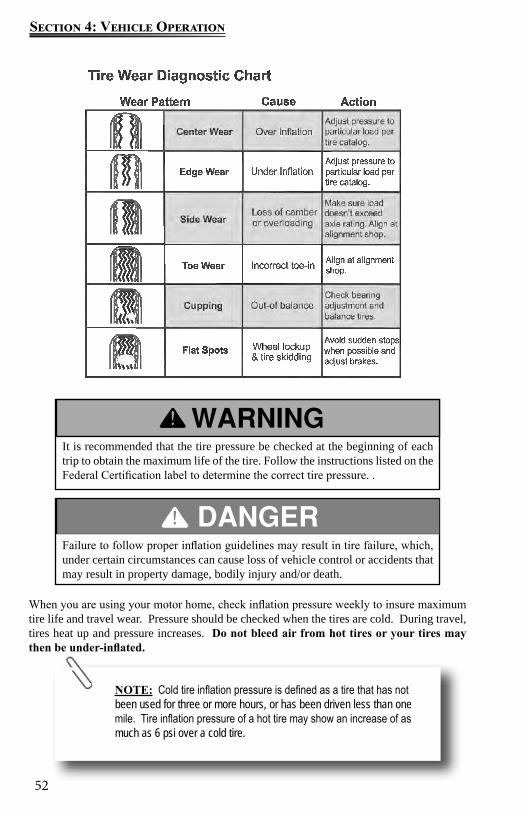
52
Section 4: Vehicle Operation
NOTE: Cold tire inflation pressure is defined as a tire that has not been used for three or more hours, or has been driven less than one mile. Tire inflation pressure of a hot tire may show an increase of as much as 6 psi over a cold tire.
It is recommended that the tire pressure be checked at the beginning of each trip to obtain the maximum life of the tire. Follow the instructions listed on the Federal Certification label to determine the correct tire pressure. .
Failure to follow proper inflation guidelines may result in tire failure, which, under certain circumstances can cause loss of vehicle control or accidents that may result in property damage, bodily injury and/or death.
When you are using your motor home, check inflation pressure weekly to insure maximum tire life and travel wear. Pressure should be checked when the tires are cold. During travel, tires heat up and pressure increases. Do not bleed air from hot tires or your tires may then be under-inflated.
53
Section 4: Vehicle Operation
The motor home is very heavy. Raising the motor home to replace the spare tire should only be done with extreme caution by a qualified technician. The vehicle could slip, causing personal injury or death. DO NOT ATTEMPT TO DO THIS YOURSELF..
Changing A Tire
If you experience a flat tire on your motor home while driving, gradually decrease your vehicle speed (if possible). Hold the steering wheel firmly and move the motor home to a safe place on the side of the road. Please contact your road service provider (if applicable) or a qualified service facility for assistance. Do not attempt to change the spare tire or jack the motor home yourself; this is why a jack and a spare tire have not been included with the motor home.
Make sure the road service technician reads and is familiar with the Chassis Guide information regarding changing the tires. Make sure the wheel lug nuts have been tightened to the proper torque as outlined in your Chassis Guide.
Tire pressure is the most important factor in the life and performance of your tires. Proper inflation should be monitored closely. Failure to do so could result in the overheating of a tire, which could result in a blowout. Inflation pressure should be as recommended by the tire manufacturer or as the federal label for the motor home indicates.
Do not use the hydraulic leveling jack system to support the motor home while under the vehicle or changing tires. The hydraulic leveling system is designed as a leveling system only. Do not use the hydraulic leveling jack system as a jack or in conjunction with a jack. It is highly recommended that, should a tire change be required, it be performed by a knowledgeable, trained professional. Attempts to change tires while supporting the motor home with the hydraulic leveling jack system could result in damage to the motor home and risk causing serious injury or death..
When replacing a tire, make sure to replace it with a tire of the same size and specifications (refer to your Chassis Guide for assistance.)
Patio Awning
Awnings must be closed (and locked if applicable) while the RV is in transit.

54
Section 4: Vehicle Operation
The effects of wind and rain on an awning are unpredictable and can cause severe damage to the awning and/or the recreation vehicle. Retract the awning if:
If wind or extended periods of rain are expected If you leave the RV unattended for a length of time to avoid unexpected
climate conditions.
Operating Power Awnings (If So Equipped)
Your recreation vehicle may be equipped with multiple (power) awnings which will each have its own control switch. The control switch(s) for each awning is typically located on the command center switch panel located inside the entrance door. Pressing and holding the switch will extend or retract the awning.
Carefree® LONGITUDE Awnings (If So Equipped)These awnings offer various features that make them easy and convenient to use. These features include:
If weather conditions are windy or stormy, close the awning(s) into the travel mode position.
It is recommended that if leaving the RV unattended for a length of time, retract the awning to avoid unexpected climate conditions.
The effects of wind and rain on an awning are unpredictable and can cause severe damage to the awning and/or the recreation vehicle. If wind or extended periods of rain are expected, retract the awning.
Awning careKeep your awnings clean and in good condition to prevent costly repairs.
Periodically check that the fasteners are tight. Tighten if necessary. Keep the awning fabric clean. For detailed cleaning information, refer to the
manufacturer’s owner information included in the Warranty Packet.The 12-volt power awning (if so equipped) may need to be adjusted (retracted) to operate the entry door (some models).
For detailed safety and operating information, refer to the manufacturer’s user guide included in the Warranty Packet.
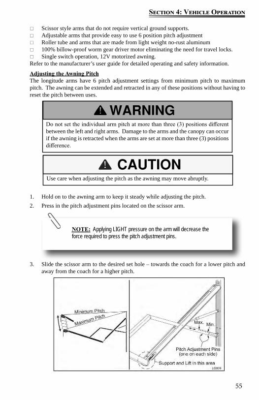
55
Section 4: Vehicle Operation
Do not set the individual arm pitch at more than three (3) positions different between the left and right arms. Damage to the arms and the canopy can occur if the awning is retracted when the arms are set at more than three (3) positions difference.
Scissor style arms that do not require vertical ground supports. Adjustable arms that provide easy to use 6 position pitch adjustment Roller tube and arms that are made from light weight no-rust aluminum 100% billow-proof worm gear driver motor eliminating the need for travel locks. Single switch operation, 12V motorized awning.
Refer to the manufacturer’s user guide for detailed operating and safety information.
Adjusting the Awning PitchThe longitude arms have 6 pitch adjustment settings from minimum pitch to maximum pitch. The awning can be extended and retracted in any of these positions without having to reset the pitch between uses.
1. Hold on to the awning arm to keep it steady while adjusting the pitch.2. Press in the pitch adjustment pins located on the scissor arm.
3. Slide the scissor arm to the desired set hole – towards the coach for a lower pitch and away from the coach for a higher pitch.
Use care when adjusting the pitch as the awning may move abruptly.
NOTE: Applying LIGHT pressure on the arm will decrease the force required to press the pitch adjustment pins.
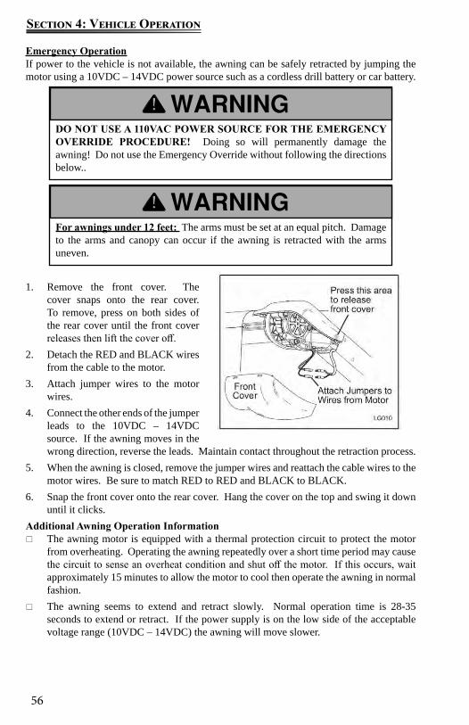
56
Section 4: Vehicle Operation
Emergency OperationIf power to the vehicle is not available, the awning can be safely retracted by jumping the motor using a 10VDC – 14VDC power source such as a cordless drill battery or car battery.
1. Remove the front cover. The cover snaps onto the rear cover. To remove, press on both sides of the rear cover until the front cover releases then lift the cover off.
2. Detach the RED and BLACK wires from the cable to the motor.
3. Attach jumper wires to the motor wires.
4. Connect the other ends of the jumper leads to the 10VDC – 14VDC source. If the awning moves in the wrong direction, reverse the leads. Maintain contact throughout the retraction process.
5. When the awning is closed, remove the jumper wires and reattach the cable wires to the motor wires. Be sure to match RED to RED and BLACK to BLACK.
6. Snap the front cover onto the rear cover. Hang the cover on the top and swing it down until it clicks.
Additional Awning Operation Information The awning motor is equipped with a thermal protection circuit to protect the motor
from overheating. Operating the awning repeatedly over a short time period may cause the circuit to sense an overheat condition and shut off the motor. If this occurs, wait approximately 15 minutes to allow the motor to cool then operate the awning in normal fashion.
The awning seems to extend and retract slowly. Normal operation time is 28-35 seconds to extend or retract. If the power supply is on the low side of the acceptable voltage range (10VDC – 14VDC) the awning will move slower.
DO NOT USE A 110VAC POWER SOURCE FOR THE EMERGENCY OVERRIDE PROCEDURE! Doing so will permanently damage the awning! Do not use the Emergency Override without following the directions below..
For awnings under 12 feet: The arms must be set at an equal pitch. Damage to the arms and canopy can occur if the awning is retracted with the arms uneven.
57
Section 4: Vehicle Operation
If the awning does not operate, contact the Carefree Service Center. Visit the Carefree website at www.carefreeofcolorado.com for a listing of service centers.
Always operate the awning according to the instructions. Periodically check that the fasteners are tight. (Tighten if necessary) Keep the awning fabric and arms clean.

58
Section 4: Vehicle Operation
Notes:
59
Section 5: Slideout Systems
Make sure the interior slideout room path and the slideout room itself is clear of people and objects before operating. Keep away from the slide rails and gear assembly when the room is in motion. They may pinch or catch on loose clothing causing personal injury. Failure to follow these instructions could result in serious injury or death.
Make sure the motor home is level before operating the slideout room. Water leaks and other problems could result if the slideout is operated without leveling the motor home...
Do not place excessive weight in the slideout room. It can cause the slideout room to malfunction and cause damage to the slideout.
Electric Slide Room(s)
The slideout room system is designed for additional floor space and comfort. Electric powered slideout room systems have a manual override to allow you to extend or retract the slideout room(s) in case of a power loss.
Make sure you have sufficient power available before operating your slideout system. Slideout switches are typically located inside the RV, either in the command center or
on the wall. To extend the slideout, locate the slideout control switch and press the OUT section of
the switch; hold until the slideout room stops (travel time is approx. 25 seconds). To retract the slideout, press the IN section of the slideout control switch and hold it
until the slideout is fully retracted. Operating the switch after the room is fully extended or retracted may damage the switch and motor.
Troubleshooting the SlideoutIf the slideout does not move when the slideout switch is depressed, follow these steps.
Check the auxiliary battery (customer supplied) for a full charge and good wire connections.
Check the 12-volt fuse or circuit breaker. Check for loose connections at the slideout motor.
If the slideout still will not operate, follow these steps.
If the slideout is extended, refer to the section on operating the specific slideout system installed on your RV.
If the slideout is retracted, leave it in that position. Contact your dealer or customer service for repair assistance.
60
Section 5: Slideout Systems
NOTE: Do not operate the switch after the room is fully extended as damage can occur to the motor and/or switch..
Additional support jacks are not needed under the slideout. Damage can occur to your slideout room from improper use of aftermarket support jacks.
Slideout SystemsYour RV may be equipped with one or more of the following slideout systems.
Schwintek Inwall slideout systemThe in-wall slideout system requires no maintenance it will never require any adjustments. This system has two vertical columns. Each side has a drive motor located at the top of the column. The right and left hand motors remain synchronized by a circuit board.
1. The auxiliary battery (customer supplied) must be fully charged and connected. When possible, the recreation vehicle should be hooked up to 120-volt AC power so the converter operates.
2. The recreation vehicle must be level and the stabilizer jacks in the extended position.3. Slideout switches are typically located on the inside of the recreation vehicle, either in
the command center panel or on the wall. To move the room out, press the OUT section of the switch and hold it until the motor stops (travel time is approx. 25 seconds
Some models may be equipped with a wireless remote control to operate the slideout. To operate the slideout using the remote:
Press the on/off button to power on the remote. Select the slideout you want to operate by pressing the corresponding button. Press and hold the (extend/retract) arrow button to move the room in or out. Press the on/off button once more to power off the remote.
DO NOT try and time the end of the stroke by releasing the button early.
ALWAYS allow the controller to stop both motors before releasing the switch button.
Retracting slideout roomPress the IN section of the slideout control switch and hold it until the motor stops.
NOTE: Operating the switch after the room is fully retracted will damage the switch and motor.
61
Section 5: Slideout Systems
Do not work on your system unless the 12-volt DC (auxiliary battery, customer supplied) and 120-volt AC electrical systems (shore line power cord) have been disconnected.
Maintenance
Your slideout system has been designed to require very little maintenance. To ensure a long life of your slideout system, read, understand and follow these simple instructions. This system contains a pre-lubed bearing that is lubricated when the room is moved in and out. Do not spray oil or grease on the rails while the room is extended.
Trouble shooting the Inwall slideout systemChecking Fuses: The inwall slide requires a minimum 30 Amp fuse. Check the load center for blown fuses and replace any if necessary.
If the fuse blows immediately upon replacement, there is a problem with the wiring to the inwall slide control box. A qualified service person should be called to check and repair.
Obstructions: Check outside for possible obstructions such as a tree, post or car etc. Check inside the vehicle for any obstructions such as luggage, furniture or open cabinets etc. Also check for smaller objects that may be wedged under the floor or in the sides of the unit. Remove any obstructions before proceeding.
Error Codes: Refer to the error codes section for codes and instructions on how to locate the inwall slide controller.
Low Voltage: The inwall slide controller is capable of operating the room with as little as 8 volts. But at these lower voltages the amperage requirement is greater. Check the voltage at the controller. If voltage is lower than 11 volts, it is recommended that the battery be placed on a charger until it is fully charged. It may be possible to “jump” the RV battery temporarily to extend or retract the room. Consult Customer Service before attempting to “jump” the auxiliary battery.
Only 1 Side Moving: The slide room has a separate motor to operate each side of the room. If only 1 side of the room is moving, then with another person’s assistance press the switch to extend or retract the room while pushing the non-moving side in the appropriate direction. On larger rooms it may be necessary to have 2 or more people pushing the room.
Non-moving side moved manually: Try to push the non-moving side in and out. If a motor shaft has broken then it will be possible to move that side of the room several inches by hand. Larger rooms may require several people to push.
Debris in the rack: Check all 4 gear racks on the side of the room for debris.
Do the status LEDs light? Locate the slide controller for the slideout in question. When the room slideout direction switch is actuated, do the status LEDs light up. Check this in both the extend and retract modes.
Manual override for the inwall slideoutThe slideout system comes with an “electronic” manual override. In event the slide out does not extend or retract follow these steps to override the system which should allow the slideout to be retracted.
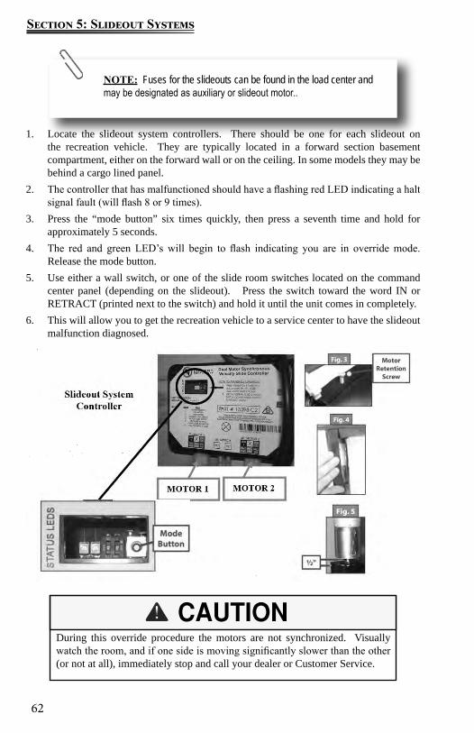
62
Section 5: Slideout Systems
1. Locate the slideout system controllers. There should be one for each slideout on the recreation vehicle. They are typically located in a forward section basement compartment, either on the forward wall or on the ceiling. In some models they may be behind a cargo lined panel.
2. The controller that has malfunctioned should have a flashing red LED indicating a halt signal fault (will flash 8 or 9 times).
3. Press the “mode button” six times quickly, then press a seventh time and hold for approximately 5 seconds.
4. The red and green LED’s will begin to flash indicating you are in override mode. Release the mode button.
5. Use either a wall switch, or one of the slide room switches located on the command center panel (depending on the slideout). Press the switch toward the word IN or RETRACT (printed next to the switch) and hold it until the unit comes in completely.
6. This will allow you to get the recreation vehicle to a service center to have the slideout malfunction diagnosed.
7.
During this override procedure the motors are not synchronized. Visually watch the room, and if one side is moving significantly slower than the other (or not at all), immediately stop and call your dealer or Customer Service.
NOTE: Fuses for the slideouts can be found in the load center and may be designated as auxiliary or slideout motor..
63
Section 5: Slideout Systems
Manually pushing in the slideout1. Locate the slideout system controller 2. Unplug motor 1 and motor 2 connectors at the bottom of the slideout controller. This
releases the motor brakes for each motor.3. The slideout room can now be manually pushed in. Larger rooms may require several
people to push or pull them.4. Keep both sides of the slideout relatively even while pushing/pulling.5. When the room is completely in, plug both motor connectors back into the control
module. This will apply the motor brakes for road travel.Disengage motors, manually retract the room and travel lock6. Locate and remove the motor retention screw which can be found near the top of each
vertical column (Fig. 3).7. Bend back the wipe seal and visually locate the motor (Fig. 4).8. Pull the motor up until it disengages (about 1/2 inch).9. Repeat this process for both sides of the slide room.10. Physically push or pull the room back into the opening, keep both sides relatively even.11. The room must be travel locked to keep the room in place for road travel.
Error CodesWhen an error code occurs during operation, the board will use the LEDs lights to indicate where the problem is. For motor specific faults the green LED will blink (1) time for motor #1 and (2) times for motor #2. The red LED will blink from 2 to 9 times depending on the error code. Error codes are as follows:
2 times Battery drop out: battery capacity low enough to drop below 6 volts while running.
3 times Low battery: voltage is below 8 volts at the start of a cycle.
4 times High battery: voltage is greater than 18 volts.
5 times Excessive motor current: high amperage, also indicated by (1) side of the slide continually stalling.
6 times Motor short circuit: motor or wiring to motor has shorted out.
8 times Hall signal not present: encoder is not providing a signal; usually a wiring problem.
If the system stalls our before reaching end of stroke OR if the room does not close and seal tightly, call your dealer Customer Service.
DO NOT MOVE THE RV UNLESS THE MOTORS ARE PLUGGED IN TO THE CONTROLLER AND THERE IS BATTERY POWER TO THE RV. THIS SETS THE BRAKES ON THE SLIDEOUTS TO PREVENT THEM FROM MOVING DURING TRANSIT.
64
Section 5: Slideout Systems
9 times Hall power short to ground: power to encoder has been shorted to ground; usually a wiring problem.
When an error code is present, the board needs to be reset. Energizing the extend / retract switch will reset the board. Energize the extend / retract switch again to go back to normal operation.Refer to the Schwintek Slide Room Operation Guide for further information. Contact Lippert or visit the Lippert website at www.lci1.com for additional troubleshooting information.
Flush Floor SlideoutFor optimum performance, the slide-out system requires full battery current and voltage. Although the system is designed to be almost maintenance free, actuate the room once or twice a month to keep the seals and internal moving parts lubricated. Check for any visible signs of external damage after and before movement of the travel trailer.
Trouble shooting the flush floor slideoutIf the slideout does not move when the slideout switch is depressed, follow these steps:
Check the auxiliary battery (customer supplied) for a full charge and good wire connections.
Check the 12-volt fuse or circuit breaker. Check for loose connections at the slideout motor. If the slideout still will not operate, follow these steps: If the slideout is extended, refer to the following section on overriding the specific
slideout system installed on your RV. If the slideout is retracted, leave it in that position. Contact your dealer or customer service for repair assistance. If the slideout extends crooked or only one side moves, follow these steps. Follow steps on overriding the specific slideout system installed on your RV. You may need to push the side that is not sliding to get it to retract all the way. Contact your dealer or customer service for repair assistance.
Manual Operation for the flush floor slideout
NOTE: For long-term storage it is recommend the room be closed (retracted).
Always disconnect battery from system prior to manually operating system. Failure to disconnect battery can cause electricity to backfeed through the motor and cause serious damage to the system as well as void the warranty
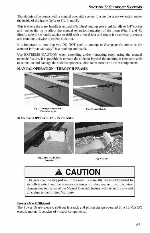
65
Section 5: Slideout Systems
The electric slide comes with a manual over ride system. Locate the crank extension under the inside of the frame (refer to Fig. 1 and 2).
This is where the crank handle (standard fifth wheel landing gear crank handle or 3/4” socket and ratchet fits on to allow the manual extension/retraction of the room (Fig. 3 and 4). Simply take the wrench, ratchet or drill with a nut driver and rotate it clockwise to retract and counterclockwise to extend slide-out.
It is important to note that you DO NOT need to attempt to disengage the motor as the actuator is “manual ready” Just hook up and crank.
Use EXTREME CAUTION when extending and/or retracting room using the manual override feature. It is possible to operate the slideout beyond the maximum extension and/or retraction and damage the slide components, slide room structure or trim components.
MANUAL OPERATION - THROUGH FRAME
MANUAL OPERATION - IN FRAME
Power Gear® SlideoutThe Power Gear® electric slideout is a rack and pinion design operated by a 12 Volt DC electric motor. It consists of 4 major components:
The gears can be stripped out if the room is manually retracted/extended to its fullest extent and the operator continues to rotate manual override. Any damage due to misuse of the Manual Override feature will disqualify any and all claims to the Limited Warranty.
Fig. 1-Through Frame Crank Extension w/pin.
Fig. 2-Crank Handle
Fig. 3-Hex Head Crank Extension
Fig. 4-Ratchet
66
Section 5: Slideout Systems
Inner rail assemblies to support the room weight. A 12 Volt DC gear motor to operate the room using power from the onboard battery. A manual override that allows you to extend or retract the room in the event of a loss
of power. A control that gives the user full control of room movement, in or out. The control has
a sensing capability that stops the motor when the room is fully extended or retracted.
Electric Operation
Extending the room1. Level the unit.2. Main Power switch at stepwell (locations may vary) must be
ON.3. Verify the battery is fully charged and hooked up to the
electrical system.4. Remove the transit bars (if so equipped).5. Press and hold the IN/OUT switch in the OUT position until the room is fully extended
and stops moving.6. Release the switch, which will lock the room into position. If the slideout switch is held
after the room is fully extended, the control will sense that the room has stopped and will shut the motor off after a few seconds.
Retracting the room 1. Verify the battery is fully charged and hooked up to the electrical system.2. Press and hold the IN/OUT switch in the IN position until the room is fully retracted
and stops moving.3. Release the switch, which will lock the room into position. If the slideout switch is held
after the room is fully extended, the control will sense that the room has stopped and will shut the motor off after a few seconds.
NOTE: For long-term storage: It is recommended the room be closed (retracted).
Always make sure the slideout room path is clear of people and objects before and during operation of the slideout room.
Always keep away from the slide rails when the room is being operated. The gear assembly may pinch or catch on loose clothing causing personal injury.
Install transit bars (if so equipped) on the slideout room during storage and transportation.
FAILURE TO FOLLOW THESE INSTRUCTIONS COULD RESULT IN SERIOUS INJURY OR DEATH.
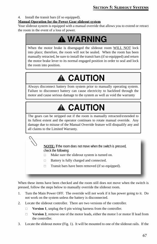
67
Section 5: Slideout Systems
4. Install the transit bars (if so equipped).Manual Operation for the Power Gear slideout systemYour slideout system is equipped with a manual override that allows you to extend or retract the room in the event of a loss of power.
When these items have been checked and the room still does not move when the switch is pressed, follow the steps below to manually override the slideout room.
1. Turn the Main Power OFF. The override will not work if it has power going to it. Do not work on the system unless the battery is disconnected.
2. Locate the slideout controller. There are two versions of the controller. Version 1, unplug the 6 pin wiring harness from the controller. Version 2, remove one of the motor leads, either the motor I or motor II lead from
the controller. 3. Locate the slideout motor (Fig. 1). It will be mounted to one of the slideout rails. If the
When the motor brake is disengaged the slideout room WILL NOT lock into place; therefore, the room will not be sealed. When the room has been manually retracted, be sure to install the transit bars (if so equipped) and return the motor brake lever to its normal engaged position in order to seal and lock the room into position.
Always disconnect battery from system prior to manually operating system. Failure to disconnect battery can cause electricity to backfeed through the motor and cause serious damage to the system as well as void the warranty
The gears can be stripped out if the room is manually retracted/extended to its fullest extent and the operator continues to rotate manual override. Any damage due to misuse of the Manual Override feature will disqualify any and all claims to the Limited Warranty.
NOTE: If the room does not move when the switch is pressed, check the following:
Make sure the slideout system is turned on. Battery is fully charged and connected. Transit bars have been removed (if so equipped).
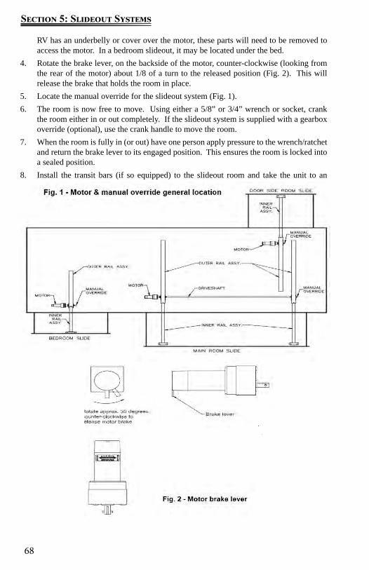
68
Section 5: Slideout Systems
RV has an underbelly or cover over the motor, these parts will need to be removed to access the motor. In a bedroom slideout, it may be located under the bed.
4. Rotate the brake lever, on the backside of the motor, counter-clockwise (looking from the rear of the motor) about 1/8 of a turn to the released position (Fig. 2). This will release the brake that holds the room in place.
5. Locate the manual override for the slideout system (Fig. 1). 6. The room is now free to move. Using either a 5/8” or 3/4” wrench or socket, crank
the room either in or out completely. If the slideout system is supplied with a gearbox override (optional), use the crank handle to move the room.
7. When the room is fully in (or out) have one person apply pressure to the wrench/ratchet and return the brake lever to its engaged position. This ensures the room is locked into a sealed position.
8. Install the transit bars (if so equipped) to the slideout room and take the unit to an authorized dealer for service.
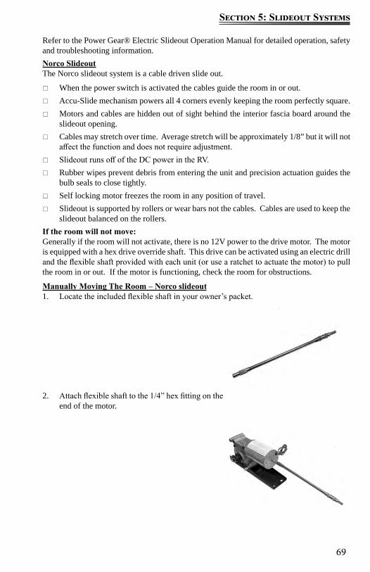
69
Section 5: Slideout Systems
Refer to the Power Gear® Electric Slideout Operation Manual for detailed operation, safety and troubleshooting information.Norco SlideoutThe Norco slideout system is a cable driven slide out.
When the power switch is activated the cables guide the room in or out. Accu-Slide mechanism powers all 4 corners evenly keeping the room perfectly square. Motors and cables are hidden out of sight behind the interior fascia board around the
slideout opening. Cables may stretch over time. Average stretch will be approximately 1/8” but it will not
affect the function and does not require adjustment. Slideout runs off of the DC power in the RV. Rubber wipes prevent debris from entering the unit and precision actuation guides the
bulb seals to close tightly. Self locking motor freezes the room in any position of travel. Slideout is supported by rollers or wear bars not the cables. Cables are used to keep the
slideout balanced on the rollers.If the room will not move:Generally if the room will not activate, there is no 12V power to the drive motor. The motor is equipped with a hex drive override shaft. This drive can be activated using an electric drill and the flexible shaft provided with each unit (or use a ratchet to actuate the motor) to pull the room in or out. If the motor is functioning, check the room for obstructions.
Manually Moving The Room – Norco slideout1. Locate the included flexible shaft in your owner’s packet.
2. Attach flexible shaft to the 1/4” hex fitting on the end of the motor.
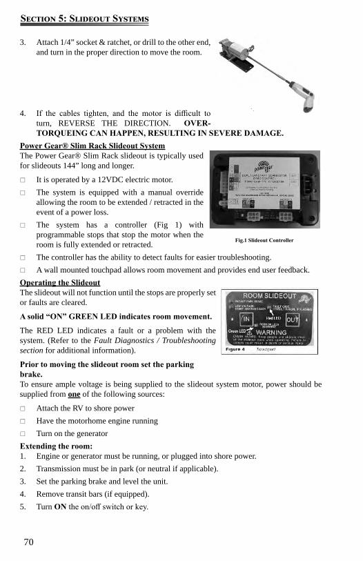
70
Section 5: Slideout Systems
3. Attach 1/4” socket & ratchet, or drill to the other end, and turn in the proper direction to move the room.
4. If the cables tighten, and the motor is difficult to turn, REVERSE THE DIRECTION. OVER-TORQUEING CAN HAPPEN, RESULTING IN SEVERE DAMAGE.
Power Gear® Slim Rack Slideout SystemThe Power Gear® Slim Rack slideout is typically used for slideouts 144” long and longer.
It is operated by a 12VDC electric motor. The system is equipped with a manual override
allowing the room to be extended / retracted in the event of a power loss.
The system has a controller (Fig 1) with programmable stops that stop the motor when the room is fully extended or retracted.
The controller has the ability to detect faults for easier troubleshooting. A wall mounted touchpad allows room movement and provides end user feedback.
Operating the SlideoutThe slideout will not function until the stops are properly set or faults are cleared.
A solid “ON” GREEN LED indicates room movement.
The RED LED indicates a fault or a problem with the system. (Refer to the Fault Diagnostics / Troubleshooting section for additional information).
Prior to moving the slideout room set the parking brake. To ensure ample voltage is being supplied to the slideout system motor, power should be supplied from one of the following sources:
Attach the RV to shore power Have the motorhome engine running Turn on the generator
Extending the room:1. Engine or generator must be running, or plugged into shore power.2. Transmission must be in park (or neutral if applicable).3. Set the parking brake and level the unit.4. Remove transit bars (if equipped).5. Turn ON the on/off switch or key.
Fig.1 Slideout Controller
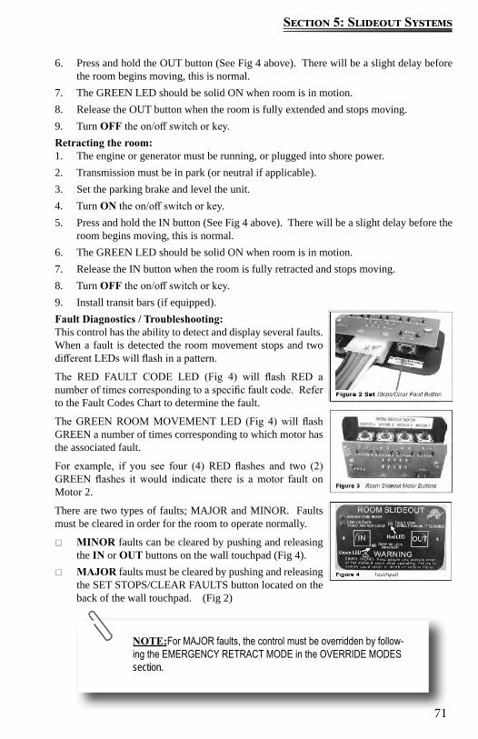
71
Section 5: Slideout Systems
6. Press and hold the OUT button (See Fig 4 above). There will be a slight delay before the room begins moving, this is normal.
7. The GREEN LED should be solid ON when room is in motion.8. Release the OUT button when the room is fully extended and stops moving.9. Turn OFF the on/off switch or key.Retracting the room:1. The engine or generator must be running, or plugged into shore power.2. Transmission must be in park (or neutral if applicable).3. Set the parking brake and level the unit.4. Turn ON the on/off switch or key.5. Press and hold the IN button (See Fig 4 above). There will be a slight delay before the
room begins moving, this is normal.6. The GREEN LED should be solid ON when room is in motion.7. Release the IN button when the room is fully retracted and stops moving.8. Turn OFF the on/off switch or key.9. Install transit bars (if equipped).Fault Diagnostics / Troubleshooting:This control has the ability to detect and display several faults. When a fault is detected the room movement stops and two different LEDs will flash in a pattern.
The RED FAULT CODE LED (Fig 4) will flash RED a number of times corresponding to a specific fault code. Refer to the Fault Codes Chart to determine the fault.
The GREEN ROOM MOVEMENT LED (Fig 4) will flash GREEN a number of times corresponding to which motor has the associated fault.
For example, if you see four (4) RED flashes and two (2) GREEN flashes it would indicate there is a motor fault on Motor 2.
There are two types of faults; MAJOR and MINOR. Faults must be cleared in order for the room to operate normally.
MINOR faults can be cleared by pushing and releasing the IN or OUT buttons on the wall touchpad (Fig 4).
MAJOR faults must be cleared by pushing and releasing the SET STOPS/CLEAR FAULTS button located on the back of the wall touchpad. (Fig 2)
NOTE:For MAJOR faults, the control must be overridden by follow-ing the EMERGENCY RETRACT MODE in the OVERRIDE MODES section.

72
Section 5: Slideout Systems
Fault Code
Fau l t Type
Fault CodesDescription Possible Cause Possible Solution
1 Major Stops not programmed
-Stops have not been set-Stops were cleared-Stops were improperly set
Steps need to be programmed by an authorized service facility.
2 Minor System Fault -Obstruction present-Excessive system drag
Run room in opposite direction. If it continues to move in the opposite direction, remove obstruction, excessive weight in room or repair of damaged component. If room stops moving in opposite direction, observe fault code and refer to this chart
4 Major E x c e s s i v e Battery Voltage
-Bad or loose connection-Defective harness-Open or shorted motor
-Check all connections at control box and motor-Check the harness for broken wires.-Put 12.0 VDC direct to the motor. If it does not run replace the motor.
6 Minor Supply voltage to control box is 17 0 V DC or greater
Check 2-pin power connector at control box. If the voltage is 17. VDC or higher, contact O.E.M for power and ground supplies
Park brake LED flashing
-Parking brake not set (if applicable )-Ground signal lost at park brake control
-Set parking brake (if applicable)-Check for continuity to ground on wire plugged into park brake connector at control box
Low voltage LED flashingIncoming violated to control box is below 12.0 VDC
Check 2-pin power connector at control box. If voltage is below 12.0 VDC contact O.E.M for power and ground supplies.
Preventative Maintenance:Your Power Gear® slideout system is designed to require very little maintenance. To ensure long life of your slideout system read and follow these few simple procedures:
When the room is extended, visually inspect the slide rail assemblies. Check for excess buildup of dirt or foreign material; remove any debris that may be present.
If the system squeaks or makes any noises, blow out any debris from the gear rack arms and apply a dry lubricant to prevent and/or stop squeaking.
Refer to the Power Gear® website (www.powergearus.com) CONTACT tab if you have any problems or questions.
OVERRIDE MODES:In the event of component failure or loss of system power, your slideout can be manually overridden and retracted for travel.
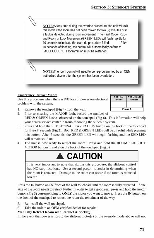
73
Section 5: Slideout Systems
Emergency Retract Mode:Use this procedure when there is NO loss of power ore electrical problem with the system.
1. Remove the touchpad (Fig 4) from the wall.2. Prior to clearing the MAJOR fault, record the number of
RED & GREEN flashes observed on the touchpad (Fig 6). This information will help your dealer/service center in troubleshooting the slideout system.
3. Press and hold the SET STOPS/CLEAR FAULTS button on the back of the touchpad for five (5) seconds (Fig 2). Both RED & GREEN LEDs will be on solid while pressing this button. After 5 seconds, the GREEN LED will begin flashing and the RED LED will remain solid on.
4. The unit is now ready to retract the room. Press and hold the ROOM SLIDEOUT MOTOR buttons 1 and 2 on the back of the touchpad (Fig 3).
Press the IN button on the front of the wall touchpad until the room is fully retracted. If one side of the room needs to retract further in order to get a good seal, press and hold the motor button (Fig 3) corresponding to ONLY the motor you want to move. Press the IN button on the front of the touchpad to retract the room the remainder of the way.
5. Re-install the wall touchpad.6. Take the unit to an OEM certified dealer for repairs.Manually Retract Room with Ratchet & Socket:In the event that power is lost to the slideout motor(s) or the override mode above will not
NOTE:At any time during the override procedure, the unit will exit this mode if the room has not been moved for two (2) minutes or if a fault is detected during room movement. The Fault Code (RED) and Room or Lock Movement (GREEN) LEDs will flash rapidly for 10 seconds to indicate the override procedure failed. After 10 seconds of flashing, the control will automatically default to FAULT CODE 1. Programming must be restarted.
NOTE:The room control will need to be re-programmed by an OEM authorized dealer after the system has been overridden.
It is very important to note that during this procedure, the slideout control has NO stop locations. Use a second person to assist in determining when the room is retracted. Damage to the room can occur if the room is retracted too far.
74
Section 5: Slideout Systems
work, the room may be manually retracted using a ratchet and socket attached to the end of the coupler (Fig 11).
1. You need to gain access to the VERTICAL CHANNEL assembly from either inside or outside of the coach (whichever is more convenient). Remove the OEM trim and flange pieces on the slideout room box.
2. If applicable, remove the top screw from the bulb seal at the top of the VERTICAL CHANNEL (Fig 8).
3. Pull down the bulb seal and remove the motor cover (Fig 9). The motor seal may stick to the bulb seal.
4. Using a pick tool, remove the end of the retaining spring from the motor spring clip (Fig 10A). If not equipped with a retaining spring, loosen the motor retaining screw (Fig 10B).
5. Unplug the motor from the harness and remove the motor by lifting it up and out.6. Repeat steps 1-4 for the other side.7. Place a socket wrench with a 3 inch extension and a 5/8” deep well socket (Fig 12)
through the motor access opening and seat the socket onto the coupler (Fig 13). One man alternating from side to side of the room can retract a 1500 lb. room with or without a ramp.
8. Secure the room in place by either: Re-installing the motors (making sure the end of the retaining screw is re-hooked
to the motor spring clip (Fig 10A). Torque the motor retaining screw to 40 inch/lbs. (Fig 10B) and the motor retainer
is fully engaged. Use a travel lock, (a 2x4 cut to size), etc. Refer to Fig 10A and 10B for proper seating of the motor.
9. Have the slideout room serviced by an OEM authorized dealer as soon as possible. Do not operate the room until service is complete as damage to the room may result.
NOTE:1 person on each side of the room with a ratchet and socket will expedite the process. Room moves ¼ inch for every 30 to 40 degree turn of the wrench.

75
Section 5: Slideout Systems
For further information refer to the Slim Rack In Wall Slide Out System Owner’s Manual ,or visit Lippert’s website @ http://www.lci1.com/assets/content/support/manuals/pg-3010002679.pdf

76
Section 5: Slideout Systems
Notes:
77
Section 6: Electrical System
In Case Of An Electrical Fire
HAVE EVERYONE EVACUATE THE RECREATION VEHICLE IMMEDIATELY.
Switch the 120-volt main circuit breaker to the “off” position. Disconnect the negative battery cable(s) at the battery. Disconnect the power cord from the shore power receptacle. Turn “off” the generator (if so equipped).
Always have faulty or damaged wiring and electrical components repaired immediately.
Use caution when using metal tools. If a tool contacts a battery terminal or metal connected to it, a short circuit could occur which could cause personal injury, explosion or fire.
Do not attempt to use water to put out an electrical fire. Water can spread some types of fire, and electrocution is possible with an electrical fire.
The Electrical System The RV electrical system is comprised of two independent electrical systems. One operates off of 12-volt DC power and the other off of 120/240-volt 60hz AC power. All installations have been made in compliance with industry standards applicable on the date of manufacture. Because the electrical equipment and associated circuitry are engineered into a dedicated system specific to your model, do not make unauthorized changes or add fixed appliances to it. Changes or additions made after delivery may result in a hazardous condition.
Service and/or modification of the electrical system should only be performed by qualified electrical technicians using approved materials, components, and methods meeting current safety and code requirements. Please consult your dealer’s service department for assistance.
To read more about the various components incorporated into the RV electrical system, refer to the component manufacturer’s user guide. Consult the Chassis Guide for information pertaining to the chassis drivetrain electrical system.
Electrical System MaintenanceAlways make sure the inverter/charger (if so equipped) is turned “off” before disconnecting batteries. Always disconnect the shore power cord, turn “off” the generator, disable automatic generator start functionality, and disconnect the negative 12-volt DC battery terminal before working on the electrical system.
Controls and SwitchesYour motor home is equipped with various switches and controls that allow you to operate and monitor the systems in your motor home.
Information on these controls and their location will be provided throughout this manual. Additional information on the various components can be found in the component manufacturer’s user guide.

78
Section 6: Electrical System
Command CenterThe command center is typically located just inside the entrance door or in the living area of the recreation vehicle. It contains switches and controls for electrical functions for the RV. Depending on your model, the command center may be a panel complete with switches, or it can be a group of switch pods mounted to a recessed panel inside a cabinet. Some models may have the switches and controls mounted directly to the wall in the living area or vicinity of the entrance door. In some cases, the systems monitor (which indicates tank levels and battery charge) may also be included on this panel (refer to the Monitor Panel section).
Command Center Panel:Items found on this panel typically include (may vary by model):
Fuel gauge and hour meter with switches for fuel pump and fuel levels Lighted red pump switch, lighted red water heater switches (electric & LP gas) Generator start / stop switch Tank heater switches Light switches for porch lights, exterior security lights, interior lights, awning LED
lights, front cap LED accent lights Cargo bed red lighted master control switch Slideout control switches (press and hold to extend / retract) Awning control switches (press and hold to extend / retract)
Mounted to wall
Command Center Panel W/Switch ModulesCommand Center Panel
NOTE: Command center configurations and components may vary from model to model. Not all components listed may be available in your model.
79
Section 6: Electrical System
Command Center Panel with Switch Modules:Items may include separate switch modules and controls that are mounted to a recessed plastic panel. Items found on this panel typically include (may vary by model):
Systems monitor with LED indicators for tank levels and battery charge status Systems monitor includes lighted red switches for pump and water heater Slideout switches (press and hold to retract / extend slideouts) Light switches for porch lights, exterior security lights, interior lights, awning LED
lights, power entry step Awning switches (press and hold to retract / extend awning) Auto leveling control panel (for leveling the recreation vehicle) Inverter panel (power switch with display) Generator start / stop control with hour meter Cargo bed red lighted master control switch Power bunk bed lift control switch Fuel gauge with fuel station on/off switch Speaker selector switch
Command Center Modules Mounted to the WallSome models may have the modules mounted directly to the interior wall of the vehicle. They are typically located near the entrance door. They may include any of the modules listed above.
Testing the Campsite Power ConnectionThe campsite 120-volt power receptacle(s) should always be tested for proper functionality prior to plugging the recreation vehicle shore power cord into it.
Campsite 120-volt power receptacles can be tested using a digital multimeter or a dedicated circuit analyzer. Dedicated circuit analyzers plug directly into the campsite power receptacle and minimally test for open neutral, open ground, and correct polarity. Polarity indicators can be purchased in most electrical and hardware stores.
GFCI ReceptacleThere is a ground fault current interrupter (GFCI) engineered into the electrical system. It is designed to reduce the possible injury caused by electric shock. The GFCI will not protect against short circuits or circuit overloads.
Test all GFCI receptacles monthly Push in the GFCI “TEST” button. The GFCI “RESET” button should pop out indicating
the GFCI receptacle has been “tripped” and interrupted 120-volt power. Push in the GFCI “RESET” button to restore 120-volt power.
Contact your independent dealer for assistance if the GFCI “RESET” button does not restore 120-volt power and pops back out.
A “tripped” GFCI breaker indicates that abnormally high 120-volt current flow (a ground fault) was detected. A fault condition can be caused by faulty wire insulation, wet wiring inside an appliance, faulty electrical equipment connected to the circuit, etc. All ground faults must be repaired before use of the recreation vehicle.
80
Section 6: Electrical System
Connecting the Power Cord
Always test the external power source (i.e., the campsite power receptacle or electrical box) with a ground monitor before connecting your power cord to it. If the ground monitor indicates ‘reverse polarity’ or an ‘open ground’ DO NOT connect the power cord.
To help prevent power surges from damaging the connected loads, please follow these instructions when hooking up to the external power source:
1. Turn “off” the load center main 120-volt circuit breaker.2. Carefully extend the entire length of the power cord (approximately 25’-35’) from the
electric cable hatch to the external power source.3. Plug the power cord into the receptacle. Be sure all the power cord prongs are properly
plugged into the receptacle.4. Return to your RV and turn “on” the load center main circuit breaker.The shore line power cord should be unplugged when the recreation vehicle is left unattended. If something would happen to the electrical system, this may help limit potential damage.
When you are ready to leave, reverse the power cord connection process. Use care to prevent damaging the power cord electrical connection pins when connecting or disconnecting the shore line power cord. Grasp the plug to remove the power cord from the outlet; do not unplug it by pulling on the cord.
MaintenanceInspect the power cord for cuts, cracks and worn insulation. Have the power cord replaced immediately if these symptoms are noticed.
Plugging the shoreline power cord into an incorrectly wired power source could damage the recreation vehicle electrical system and result in severe or fatal injury.
The power cord must be fully extended when in use and not left coiled in the electrical compartment or on the ground. If the power cord is left coiled, it may potentially create enough heat to melt its protective casing.
Inverter (If so Equpped)Your recreation vehicle may be equipped with a factory installed inverter that converts 12-volts DC to useable 120-volts AC and supplies continuous AC power to the appliance plugged into it. It is important that you familiarize yourself with the inverter function and operation. The inverter should be “off” when not in use.
The factory-installed inverter is not intended for use with medical device(s).If your recreation vehicle is equipped with a residential style refrigerator, the inverter may be used to supply the 120-volts AC necessary to power the refrigerator. The inverter has been
81
Section 6: Electrical System
carefully selected to provide proper power to operate the refrigerator safely.
Inspection and maintenanceIf the inverter is not functioning, check the fuse protecting the inverter input. If you have further concerns contact your dealer. There are no customer serviceable parts inside the inverter case and the manufacturer’s warranty will be void if the case has been removed. The inverter cooling fins and the cooling fan should be kept clear of any obstructions.
ConverterThe power converter (located in the Load Center) converts 120-volt AC power to useable 12-volt DC power when the shore power cord is connected to an external power source.
The converter has a built-in protective thermal breaker that will shut it down should overheating occur. Overheating can be caused by operating the converter above its maximum power output for an extended period of time, or by an obstruction to its ventilation air flow. To reduce converter heat build, keep unnecessary 12-volt lights and motors turned “off”. Keep the converters cooling fins and fan clear of obstructions.
Charge Wizard OperationThe converter has (3) possible charging modes; NORMAL, BOOST and STORAGE. The charge wizard will automatically select the best mode to charge your battery.
A green LED next to the wizard mode button will indicate by flashes, which mode is currently being used.
NORMAL MODE: Green LED flashes once per second; battery is between 50% and 90% charged. Green LED will flash 2-3 times per second; battery is 90% charged. Output voltage is 13.6VDC and the converter is safely completing the charge of the battery.
BOOST MODE: Green LED is on solid. Output voltage is 14.4VDC to rapidly charge the battery up to 90% of full charge.
STORAGE MODE: Green LED flashes every 6-8 seconds. Output voltage has been reduced to 13.2VDC; the RV battery is fully charged and converter is maintaining the charge.
MANUAL MODE (Not recommended): The wizard mode button is used to override the charge wizard. Refer to the converter owner’s manual for additional information.
REVERSE BATTERY PROTECTION: Reverse polarity fuse(s) provide protection for the converter when a battery is used. If the battery is connected backwards to the fuse board a fuse will blow preventing damage to the converter. Four easily accessible fuses are located next to the wizard button. Replace with fuses of the same type and rating.
Inspection and maintenanceIf the 12-volt power converter is not working (auxiliary battery not being charged) check the reverse polarity fuse(s) in the Load Center. There are no customer serviceable parts inside the converter case and the manufacturer’s warranty will be void if the case has been removed. If you have further concerns contact your dealer.
Wizard Button & Reverse
Protection Fuses
12-volt DC SystemThe majority of your motor home lighting is powered by 12-volt electricity. The 12-volt DC system is composed of components that will operate when the following conditions are met:
Power is supplied by the chassis alternator when the chassis engine is running.
82
Section 6: Electrical System
The power converter will supply interior 12-volt DC power when the shore power cord is plugged into a 120-volt external power source. The converter will also charge the house batteries in most situations.
The house batteries power many interior 12-volt components including the lighting fixtures, water pump, 12-volt motors, 12-volt appliances, etc, when the motorhome is not connected to a 120 volt power source.
12-volt Fuse PanelThe 12-volt fuse panel is labeled to indicate fuse sizes, positions and the components powered. At the beginning of camping season, inspect all the 12-volt fuses and replace as needed. Fuses are located in the Load Center.
Replacing a fuseBefore replacing a fuse, always turn off the electrical components protected by it.
1. Disconnect the shore power cord. 2. Turn “off” the inverter (if so equipped).3. Disconnect the house batteries main negative battery cable.4. Remove the fuse panel cover to check fuses.5. Pull the fuse straight out of the fuse block. If the fuse is not blown, something else must
be causing the problem. Please contact your dealer for further assistance.6. Insert a new fuse of the same specified voltage, amperage rating and type in the original
location. Never use a higher rated replacement fuse.The fuse panel label should be kept permanently affixed to your motor home. The fuses will not offer complete protection of the motor home electrical system in the event of a power surge or spike.
Replacement fuses must be of the same voltage, amperage rating and type. Never use a higher rated replacement fuse; doing so may cause a fire by overheating the RV wiring.
12-Volt DC OutletThere may be one or more 12-volt DC power outlets in your recreation vehicle. When the 12-volt DC outlet is used as a power source for an electric appliance, make sure the appliance operates on 12-volt DC power and that it consumes less than 60 watts (5 amps) of power.
Keep the protective dust cap on the 12-volt DC outlet when not in use to prevent ingestion of foreign material and potential short circuit conditions.
83
Section 6: Electrical System
Batteries
House BatteriesYour motor home is equipped with Group 27 deep cycle batteries. If the batteries need to be replaced, only deep cycle batteries of the same size and type should be installed.
Unless a battery has been fully discharged, house auxiliary batteries are normally charged in one of two ways:
When the power cord is plugged into 120-volt shore power, or when the generator (if so equipped) is operational, the inverter/charger functions as a multi-stage battery charger and will automatically charge the house auxiliary batteries when required. A bi-directional charge relay incorporated into the electrical system allows the inverter/charger to charge the chassis batteries once the house auxiliary batteries are sufficiently charged.
The chassis alternator charging system supplies power to the house auxiliary batteries when the engine is running and the chassis batteries are sufficiently charged
For more informationConsult the Chassis Guide for information pertaining to the chassis drivetrain electrical system.
A fully charged battery will read 12.65 volts DC with a specific gravity of 1.265 at 80°F (32°C). A battery is considered discharged at 11.89 DC volts or when it has a specific gravity of1.120 or less. When voltage drops to 11.89 volts, irreversible battery damage can occur.
Dry campingHouse auxiliary and chassis batteries should be fully charged prior to dry camping. When disconnected from 120-volt shore or generator power (i.e., while dry camping or tailgating) all electrically operated appliances and accessories must be used sparingly. Typically, a deep cycle battery has an amp-hour rating of 75-100 amps.
During this period these appliances and accessories are being powered by the house auxiliary batteries directly, and/or indirectly through the inverter/charger. If excessive amounts of power are drawn from the house auxiliary batteries, either as small applied loads over an extended period of time or as high applied loads for a short period of time, they will become deeply discharged. Permanent battery damage will occur after repeated deep discharge cycles
Do not store anything inside the battery compartment(s) or near the batteries that could touch the battery or battery cable terminals. Contact with the battery or battery cable terminals could cause an electrical short circuit, discharge the batteries, or start an electrical fire.

84
Section 6: Electrical System
Battery inspection & care
Check the level of electrolyte in each battery cell once a year. Add distilled water as needed to reach the split-level marker on each battery. Keep batteries and battery terminals clean and tight.
Check the external condition of the batteries periodically. Look for cracks in the cover and case. Make sure battery vent caps are tight and replace them if they are cracked or broken.
Battery storage instructionsTo prevent house auxiliary battery discharge when your motor home will not be connected to shore power for extended periods of time, it is recommended you turn “off” the 12-volt battery disconnect switch, or “main power switch,” and disconnect each battery bank at the negative battery cable running to the chassis frame.
During storage, it is important to check battery voltage at least every two weeks and to recharge them as needed. If you remove the batteries from your motor home protect them from accidental shorting and keep them in a cool, dry, well ventilated area.
Battery replacement If house auxiliary batteries need to be replaced, only deep cycle batteries of the same size and type should be installed. Refer to the Chassis Guide for information on chassis battery replacement.
Do not allow battery electrolyte (acid) to come into contact with skin, eyes, fabric or painted surfaces. Electrolyte is a sulfuric acid solution that could cause serious personal injury or property damage. If your hands, eyes, clothes or the painted surface of your motor home are exposed to electrolyte, flush the exposed area thoroughly with water. If electrolyte gets in your eyes, immediately flush them thoroughly with water and get prompt medical attention.
Make sure the inverter/charger is turned “off” before disconnecting the negative battery cable from the battery bank. Keep the batteries out of the reach of children.
Keep sparks, cigarettes and flames away from the batteries as the hydrogen gas they create may explode. Do not connect a booster battery or other power source that outputs more than 14.2-volts DC to the motor home batteries. Use adequate ventilation when charging or using batteries in an enclosed space.
Remove metal jewelry and always wear eye protection when working around batteries.
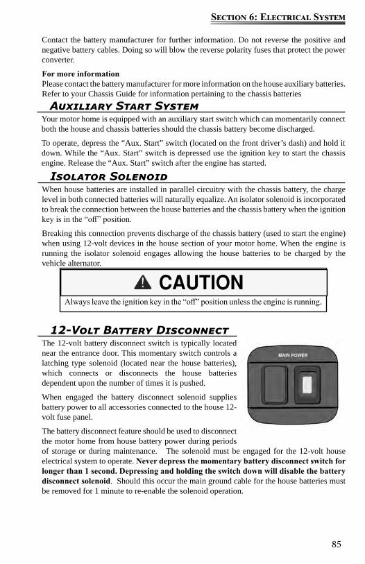
85
Section 6: Electrical System
Auxiliary Start SystemYour motor home is equipped with an auxiliary start switch which can momentarily connect both the house and chassis batteries should the chassis battery become discharged.
To operate, depress the “Aux. Start” switch (located on the front driver’s dash) and hold it down. While the “Aux. Start” switch is depressed use the ignition key to start the chassis engine. Release the “Aux. Start” switch after the engine has started.
Contact the battery manufacturer for further information. Do not reverse the positive and negative battery cables. Doing so will blow the reverse polarity fuses that protect the power converter.
For more informationPlease contact the battery manufacturer for more information on the house auxiliary batteries. Refer to your Chassis Guide for information pertaining to the chassis batteries
Isolator SolenoidWhen house batteries are installed in parallel circuitry with the chassis battery, the charge level in both connected batteries will naturally equalize. An isolator solenoid is incorporated to break the connection between the house batteries and the chassis battery when the ignition key is in the “off” position.
Breaking this connection prevents discharge of the chassis battery (used to start the engine) when using 12-volt devices in the house section of your motor home. When the engine is running the isolator solenoid engages allowing the house batteries to be charged by the vehicle alternator.
Always leave the ignition key in the “off” position unless the engine is running.
12-Volt Battery DisconnectThe 12-volt battery disconnect switch is typically located near the entrance door. This momentary switch controls a latching type solenoid (located near the house batteries), which connects or disconnects the house batteries dependent upon the number of times it is pushed.
When engaged the battery disconnect solenoid supplies battery power to all accessories connected to the house 12-volt fuse panel.
The battery disconnect feature should be used to disconnect the motor home from house battery power during periods of storage or during maintenance. The solenoid must be engaged for the 12-volt house electrical system to operate. Never depress the momentary battery disconnect switch for longer than 1 second. Depressing and holding the switch down will disable the battery disconnect solenoid. Should this occur the main ground cable for the house batteries must be removed for 1 minute to re-enable the solenoid operation.

86
Section 6: Electrical System
Load CenterThe Load Center contains 12VDC fuses and 120VAC circuit breakers for almost all of the electrical appliances and circuits in the RV. The 120V Main Breaker (if so equipped) is located in this panel and will turn off all 120-volt power to the recreation vehicle. The load center is a hinged panel typically attached to a cabinet face in the main living area. Locations will vary by model. Refer to the diagram inside the Load Center for specific fuse assignments. Most load centers contain the same components, but they may be positioned differently. Not all load centers will include a main breaker.
Typical Load Center Exterior Panel
Load Center Panel w/120 volt Main breaker
Load center appearance and configuration may vary by model
Approximate Electrical Load Ratings12 Volt System
Aisle Lights 1.0 AMPBaggage Compartment Lights 1.4 AMPSDecorative Wall Lights 1.5 AMPSDinette Light 4.5 AMPSExterior Entertainment Center 5-7 AMPSFantastic Fan 1.5 AMPSFluorescent Double Lights -12” 2.0 AMPSFluorescent Double Lights -18” 2.5 AMPSFurnace 12.0 AMPSGenerator Start 95.0 AMPS*Halogen Light 1.7 AMPSIlluminated Switch .125 AMPInverter variableLeveling System 95.0 AMPS*LP Detector .125 AMPMap Light 1.5 AMPSPorch Light 1.5 AMPS
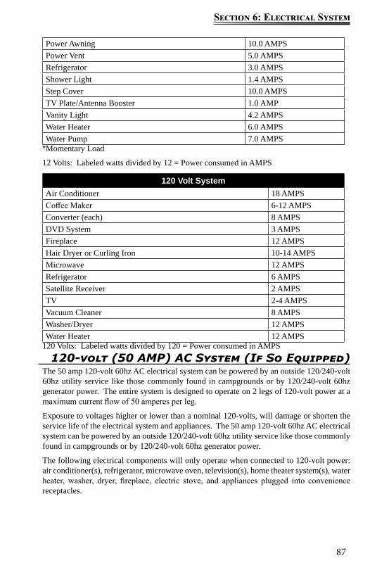
87
Section 6: Electrical System
Power Awning 10.0 AMPSPower Vent 5.0 AMPSRefrigerator 3.0 AMPSShower Light 1.4 AMPSStep Cover 10.0 AMPSTV Plate/Antenna Booster 1.0 AMPVanity Light 4.2 AMPSWater Heater 6.0 AMPSWater Pump 7.0 AMPS
*Momentary Load
12 Volts: Labeled watts divided by 12 = Power consumed in AMPS
120 Volt SystemAir Conditioner 18 AMPSCoffee Maker 6-12 AMPSConverter (each) 8 AMPSDVD System 3 AMPSFireplace 12 AMPSHair Dryer or Curling Iron 10-14 AMPSMicrowave 12 AMPSRefrigerator 6 AMPSSatellite Receiver 2 AMPSTV 2-4 AMPSVacuum Cleaner 8 AMPSWasher/Dryer 12 AMPSWater Heater 12 AMPS
120 Volts: Labeled watts divided by 120 = Power consumed in AMPS120-volt (50 AMP) AC System (If So Equipped)
The 50 amp 120-volt 60hz AC electrical system can be powered by an outside 120/240-volt 60hz utility service like those commonly found in campgrounds or by 120/240-volt 60hz generator power. The entire system is designed to operate on 2 legs of 120-volt power at a maximum current flow of 50 amperes per leg.
Exposure to voltages higher or lower than a nominal 120-volts, will damage or shorten the service life of the electrical system and appliances. The 50 amp 120-volt 60hz AC electrical system can be powered by an outside 120/240-volt 60hz utility service like those commonly found in campgrounds or by 120/240-volt 60hz generator power.
The following electrical components will only operate when connected to 120-volt power: air conditioner(s), refrigerator, microwave oven, television(s), home theater system(s), water heater, washer, dryer, fireplace, electric stove, and appliances plugged into convenience receptacles.
88
Section 6: Electrical System
Circuit breakers and fuses will not offer complete protection of the electrical system in the event of power surge or voltage spike.
Make certain the external power source you connect the power cord to is a properly wired 50 amp NEMA 14-50 RV receptacle and not 240 volt AC.
50-amp Power Cord (If So Equipped)
The 50 amp external utility power cord is commonly referred to as the “shore” power cord. It is designed to mate and properly function with 50 amp “shore” power receptacles available at most campgrounds.
The shore power cord is designed to continuously carry the 50 amp current flow required to power each leg of the electrical system. It also creates a critical ground connection between the vehicle electrical system and the campground shore power receptacle.
PLUG INTO 50-AMP SERVICE ONLY.
Calculating 50 AMP Electrical Load (If So Equipped)
When connecting appliances to the electrical system, remember that 120-volt power usage is limited to 50 amps per electrical system leg for a total of 100 amps. Be mindful of the fact that each operating appliance collectively places an added load on your 120-volt electrical system.
An unintentional “trip” of a circuit breaker may occur if you overload the recreation vehicle and/or campground electrical system. The amperage rating of individual appliances can be calculated by dividing appliance wattage consumed (normally listed on the appliance) by nominal design voltage (120 for a 120-volt appliance). For example: 1200 watts divided by 120-volts equals 10 amps.
Only connect the shore power cord to RV 50 amp 120/240 volt electrical power receptacles.

89
Section 6: Electrical System
Do not hook up the power cord to any receptacle until you have verified proper polarity and grounding. Polarity indicators can be purchased in most electrical and hardware stores.
Do not use any cheater plug, adapter or extension cord to reconfigure incoming AC power or break the continuity of the circuit connected to the grounding pin.
Do not connect the power cord into an outlet that is not grounded, or adapt the power cord plug to connect it to a receptacle for which it is not designed.
Do not remove the grounding pin to connect to a non-grounded receptacle. Removal of the ground pin disables an important safety feature designed to prevent shock and electrocution hazards.
Do not connect the power cord to an extension cord. Use of an improper extension cord will cause overheating of the cord as well as potentially causing premature failure of the AC equipment.
It is the responsibility of the owner of the electrical receptacle to ensure that the receptacle is properly wired and grounded. Reverse polarity and/or improper grounding of your recreation vehicle can cause personal injury or death.
120-volt Circuit BreakersThe 120-volt AC circuit breakers located inside the load center protect all 120-volt wiring and components in the recreation vehicle from circuit overloads and short circuits. Should a circuit overload or short circuit occur the circuit breaker protecting the affected circuit will “trip” preventing the flow of electricity through that circuit.
If a circuit breaker trips, shut “off” the appliance on that circuit (i.e., power converter etc.) and allow the circuit breaker to cool down for a brief period of time. After the cooling down period, reset the circuit breaker by moving its lever “off” and then back to the “on” position. If the circuit breaker re-trips or frequently trips, contact your dealer to have the electrical problem diagnosed and repaired.
A circuit breaker identification label is permanently attached to the inside surface of the 120-volt Load Center. 120-volt circuit breakers are located in the sub-panels inside the cabinet above the driver seat.
NOTE: Load Centers may not always include a main circuit breaker.
Circuit breakers and fuses will not offer complete protection of the electrical system in the event of power surge or voltage spike.
90
Section 6: Electrical System
ReplacementOnly replace circuit breakers with those of the same specified type, voltage, and current rating. Never replace a circuit breaker with one listed at a higher amperage rating. Please contact your dealer for repair assistance when replacing circuit breakers.
Maintenance At the beginning of camping season, inspect the circuit breakers and replace as needed. Test by turning each circuit breaker “off” and back “on”. Circuit breakers are wearable parts and must be replaced as needed, as part of your RV maintenance. If you have any questions, consult your dealer.
A label is provided to explain the function of every 120-volt circuit breaker. This label is located on or near the appropriate load center or sub-panel and must remain permanently affixed to the recreation vehicle.
Replacement circuit breakers must be of the same voltage, amperage rating and type. Never use a higher rated replacement circuit breaker; doing so may cause a fire by overheating the RV wiring.
NOTE: The diesel generator requires 12-volt power from the house auxiliary batteries to start, and draws diesel fuel to operate from the chassis fuel tank. If the fuel level in the chassis fuel tank drops to or below ¼ full, the generator will automatically shut “off” and cannot be re-started until the fuel tank is filled to above ¼ full.
CARBON MONOXIDE IS DEADLY! Do not run the generator when your motor home is indoors or in a confined space. Asphyxiation or carbon monoxide poisoning hazards exist whenever generator exhaust gasses can accumulate.
GeneratorYour motor home may be equipped with a diesel powered generator and a generator slide tray. The generator produces 120/240-volt power compatible with the motor home electrical system. It can be used to power the entire motor home when 120/240-volt shore power is not available.
Transfer switchThe generator interfaces with the 120/240-volt electrical system through a transfer switch that automatically switches between available shore power and generator power. The transfer switch does not require any manual operation. When the generator is operating, it powers the inverter/charger which in turn functions as a multi-stage battery charger to charge the house auxiliary and chassis batteries.
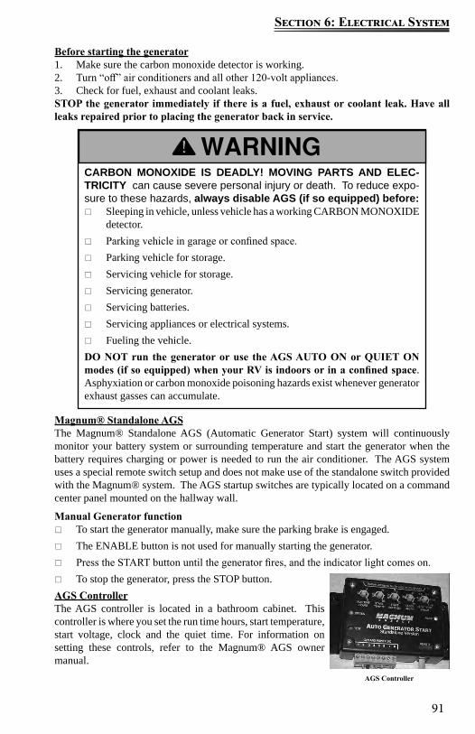
91
Section 6: Electrical System
CARBON MONOXIDE IS DEADLY! MOVING PARTS AND ELEC-TRICITY can cause severe personal injury or death. To reduce expo-sure to these hazards, always disable AGS (if so equipped) before:
Sleeping in vehicle, unless vehicle has a working CARBON MONOXIDE detector.
Parking vehicle in garage or confined space. Parking vehicle for storage. Servicing vehicle for storage. Servicing generator. Servicing batteries. Servicing appliances or electrical systems. Fueling the vehicle.
DO NOT run the generator or use the AGS AUTO ON or QUIET ON modes (if so equipped) when your RV is indoors or in a confined space. Asphyxiation or carbon monoxide poisoning hazards exist whenever generator exhaust gasses can accumulate.
Before starting the generator1. Make sure the carbon monoxide detector is working.2. Turn “off” air conditioners and all other 120-volt appliances.3. Check for fuel, exhaust and coolant leaks. STOP the generator immediately if there is a fuel, exhaust or coolant leak. Have all leaks repaired prior to placing the generator back in service.
Magnum® Standalone AGSThe Magnum® Standalone AGS (Automatic Generator Start) system will continuously monitor your battery system or surrounding temperature and start the generator when the battery requires charging or power is needed to run the air conditioner. The AGS system uses a special remote switch setup and does not make use of the standalone switch provided with the Magnum® system. The AGS startup switches are typically located on a command center panel mounted on the hallway wall.
Manual Generator function To start the generator manually, make sure the parking brake is engaged. The ENABLE button is not used for manually starting the generator. Press the START button until the generator fires, and the indicator light comes on. To stop the generator, press the STOP button.
AGS ControllerThe AGS controller is located in a bathroom cabinet. This controller is where you set the run time hours, start temperature, start voltage, clock and the quiet time. For information on setting these controls, refer to the Magnum® AGS owner manual.
AGS Controller
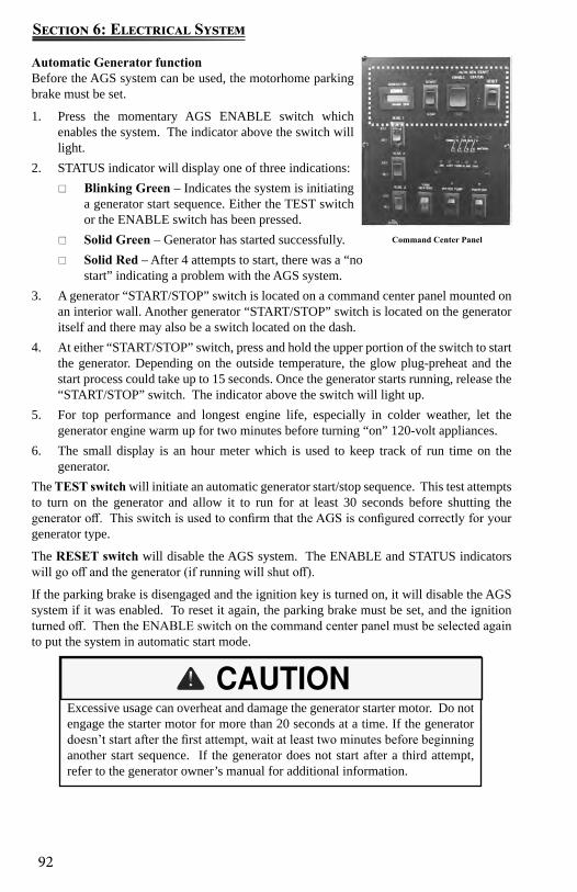
92
Section 6: Electrical System
Automatic Generator functionBefore the AGS system can be used, the motorhome parking brake must be set.
1. Press the momentary AGS ENABLE switch which enables the system. The indicator above the switch will light.
2. STATUS indicator will display one of three indications: Blinking Green – Indicates the system is initiating
a generator start sequence. Either the TEST switch or the ENABLE switch has been pressed.
Solid Green – Generator has started successfully. Solid Red – After 4 attempts to start, there was a “no
start” indicating a problem with the AGS system.3. A generator “START/STOP” switch is located on a command center panel mounted on
an interior wall. Another generator “START/STOP” switch is located on the generator itself and there may also be a switch located on the dash.
4. At either “START/STOP” switch, press and hold the upper portion of the switch to start the generator. Depending on the outside temperature, the glow plug-preheat and the start process could take up to 15 seconds. Once the generator starts running, release the “START/STOP” switch. The indicator above the switch will light up.
5. For top performance and longest engine life, especially in colder weather, let the generator engine warm up for two minutes before turning “on” 120-volt appliances.
6. The small display is an hour meter which is used to keep track of run time on the generator.
The TEST switch will initiate an automatic generator start/stop sequence. This test attempts to turn on the generator and allow it to run for at least 30 seconds before shutting the generator off. This switch is used to confirm that the AGS is configured correctly for your generator type.
The RESET switch will disable the AGS system. The ENABLE and STATUS indicators will go off and the generator (if running will shut off).
If the parking brake is disengaged and the ignition key is turned on, it will disable the AGS system if it was enabled. To reset it again, the parking brake must be set, and the ignition turned off. Then the ENABLE switch on the command center panel must be selected again to put the system in automatic start mode.
Command Center Panel
Excessive usage can overheat and damage the generator starter motor. Do not engage the starter motor for more than 20 seconds at a time. If the generator doesn’t start after the first attempt, wait at least two minutes before beginning another start sequence. If the generator does not start after a third attempt, refer to the generator owner’s manual for additional information.
93
Section 6: Electrical System
Replacing Light BulbsBefore replacing a bulb, be sure the light is off. Do not touch the glass part of the new bulb with your bare fingers. The skin oil left on the glass will evaporate when the bulb gets hot, the vapor will condense on the reflector and it will dim the surface.
Replacement light bulbs must be of the type, voltage and wattage listed on the lamp fixture. Use of incorrectly sized bulbs can overload lam circuits and may create a fire hazard by overheating the fixture.
MaintenanceFollow the generator owner’s manual for maintenance intervals and recommendations.
During periods of extended storage:
1. Add a diesel fuel additive to the chassis fuel tank to prevent algae growth.2. Completely fill the chassis diesel fuel tank to prevent water condensation and rust in
the tank.3. Cover the end of the generator exhaust pipe with screen to prevent bug and rodent
intrusion.With the exception of simple items, such as normal maintenance (i.e., oil changes, etc.), all service work should be done by an authorized repair facility. Improper adjustments can damage the generator and electrical appliances and can result in a safety hazard.
Exercising Your Generator – It’s also very important to run your generator regularly, to keep everything in good working order and in the case of gasoline sets, to avoid fuel varnishing, which can affect performance, if the generator is stored for an extended time.
Lack of exercise can cause moisture build-up and fuel system degradation that make it run poorly. In as little as 30 days, the fuel in gasoline-powered generators can begin to gum and varnish the fuel system. Fuel varnishing results in hard starting and surging. (A surging generator never settles at a stable operating speed.)
To prevent such problems, it is recommended to run gasoline generators at a minimum of 50 percent capacity (2000-watts, or one air conditioner for a 4000-watt set) for two hours once every four weeks. This is necessary to help keep moving parts lubricated, expel moisture and control fuel varnishing in the carburetor. A long two-hour exercise period is preferable to several short periods. While traveling, this can be accomplished by running the air conditioning.
For additional information on generator operation and maintenance, refer to the generator owner’s manual.

94
Section 6: Electrical System
Notes:
95
Section 7: Fuel & Propane System
Diesel Fuel & FillFor your protection and others, it is critical to understand the danger associated with fuel. Take time to become educated about the property of fuel and use it safely.
Fuel selectionUse diesel fuel only. Remember the diesel generator (if so equipped) is also fueled by the same system used to fuel the motor home chassis engine. Consider the fuel requirements of the diesel generator (if so equipped) when making a decision on the type of fuel to use.
DEF FluidDiesel engines (since 2010) require the use of DEF fluid (Diesel Exhaust Fluid) to aid in burning particulate matter in the exhaust and reduce emissions to nitrogen and water. This DEF fluid is kept in a separate heated tank and is required for the normal operation of the diesel engine. DEF tank is typically located in one of the exterior compartments and the tank will have a blue cap with “DEF” written on it. There will be a series of warnings at the dash before running out of DEF fluid. If the vehicle is allowed to run out of DEF fluid, engine power is intentionally reduced and speed will be limited to 5 MPH until the tank is re-filled.
Automotive fuels can cause serious injury or death if misused or mishandled. If you have further questions, consult your dealer or Customer Service for assistance.
Always shut OFF the vehicle engine while refueling. Do not bring or store fuel or other flammable liquids inside the motor
home because a fire or explosion may result. Before refueling, extinguish all smoking materials and any open flames. Before refueling, always turn OFF all spark producing appliances (i.e.,
water heaters, furnaces, etc.). Do not overfill the fuel tank(s). The pressure in an overfilled fuel tank
may cause leakage and lead to fuel spray and/or fire. Fuel spills represent a serious fire hazard, and should be cleaned up
immediately. Never restart an engine or re-light any pilot lights while raw fuel is
present.FAILURE TO COMPLY COULD RESULT IN FIRE, DEATH OR SERIOUS INJURY.
NOTE: If your motor home is equipped with a diesel generator, check the diesel generator and chassis manufacturer’s information to help you determine the type of diesel fuel best suited for this dual application.
96
Section 7: Fuel & Propane System
Fuel spills represent a serious fire hazard, and should be cleaned up immediately. Never restart an engine or re-light any pilot lights while raw fuel is present.
If you spill fuel on the motor home, clean it up immediately. Fuel can dull or soften paint and damage other surfaces.
Fuel SafetyFor your protection and others, it is critical to understand the danger associated with fuel. Take time to become educated about the property of fuel and use it safely.
Fuel selectionRemember the generator is also fueled by the same system used to fuel the chassis engine. Check the generator manufacturer and the chassis manufacturer information to help determine the type of fuel best suited for this dual application.
Automotive fuels can cause serious injury or death if misused or mishandled. If you have further questions, consult your dealer or Customer Service for assistance.
Always shut OFF the vehicle engine while refueling.
Do not bring or store fuel or other flammable liquids inside the motor home because a fire or explosion may result.
Before refueling, extinguish all smoking materials and any open flames.
Before refueling, always turn OFF all spark producing appliances (i.e., water heaters, furnaces, etc.).
Do not overfill the fuel tank(s). The pressure in an overfilled fuel tank may cause leakage and lead to fuel spray and/or fire.
Fuel spills represent a serious fire hazard, and should be cleaned up immediately.
Never restart an engine or re-light any pilot lights while raw fuel is present.
FAILURE TO COMPLY COULD RESULT IN FIRE, DEATH OR SERIOUS INJURY.
97
Section 7: Fuel & Propane System
Fuel filler cap
Remove the fuel filler cap by slowly turning it counterclockwise and waiting for any “hiss” noise to stop. Then unscrew the cap all the way. To close the fuel filler cap, securely turn the cap clockwise until you hear clicking sounds.
Filling the fuel tankIf you spill fuel on the motor home, clean it up immediately. Fuel can dull or soften paint and damage other surfaces. Use care when fueling your motor home.
Fuel EconomyFuel economy depends on many factors. Your driving habits can significantly affect your fuel economy. Some recommendations for achieving maximum fuel economy are shown:
Keep your tires inflated to the recommended pressures. Keep your motor home “tuned-up.” An out-of-tune engine wastes fuel and costs you
money. Keep your air cleaner clean and your motor home lubricated according to the
recommendations in this manual and the Chassis Guide. Do not overload your motor home or tow heavy loads.
Exhaust Gas Fumes
To avoid breathing exhaust gases, follow these precautions:
Do not run the engine in confined areas, such as a closed garage, any longer than needed to move your motor home in or out of the area.
Windows should be closed while driving or running the generator (if so equipped) to avoid drawing dangerous exhaust gases into the motor home.
Avoid inhaling exhaust gases as they contain carbon monoxide, which is a potentially toxic gas that is colorless and odorless.
If you are in a parked motor home with either the engine running or the generator running there is a potential for exhaust fumes to filter back into the motor home.
Do not replace the fuel fill cap with one of a different type. Only use a cap specified for your motor home. Use of a substitute cap may create excessive fuel system pressure, resulting in fuel station damage and improper operation in a collision.
98
Section 7: Fuel & Propane System
If you suspect that exhaust fumes are entering the passenger compartment, have the cause determined and corrected as soon as possible.
If you must drive under these circumstances, close all the windows, and adjust the heating or cooling system to force outside air into the motor home (set the blower on high speed).
The best protection against carbon monoxide entry into the motor home is a properly maintained ventilation system and an active carbon monoxide detector. To allow for proper operation of the motor home ventilation system, keep the ventilation inlet grill(s) clear of snow, leaves or other obstructions at all times.
MaintenanceIt is recommended that the exhaust system and vehicle body be inspected by a qualified motor home service center:
Each time the engine is ready for an oil change. Whenever a change in the sound of the exhaust is noticed. Whenever the exhaust system, underbody or rear of the vehicle is damaged.
To allow for proper operation of the motor home ventilation system, keep the ventilation inlet grill clear of snow, leaves or other obstructions at all times.
For more information refer to your Chassis Guide.
Propane Gas System (If so equipped)Propane or LP (liquefied petroleum) gas is a clean and efficient form of energy when proper handling and safety precautions are observed. The propane system in your motor home furnishes the fuel for cooking, heating, hot water and propane generator (if so equipped). Propane can also be used as an alternative energy source for refrigeration.
The propane fuel system is comprised of numerous components such as the propane container, hoses, the propane gas regulator, piping and copper tubing lines to each appliance.
Propane is heavier than air; the gas tends to flow to lower areas and will sometimes pocket in these low areas, such as the floor. Your motor home is equipped with a propane alarm (refer to Safety Precautions, Combination Carbon Monoxide (CO)/Propane Alarm).
The following label should be kept permanently affixed to the motor home:
Propane cylinders should not be placed or stored inside the vehicle. LP-gas cylinders are equipped with safety devices that relieve pressure by discharging gas into the atmosphere.
99
Section 7: Fuel & Propane System
MaintenanceAlthough your motor home has been carefully tested at the factory and by your selling dealer for leakage, travel vibrations can loosen fittings. Have the vehicle propane system checked at all connections soon after the purchase of your vehicle, and after the initial filling of the propane tanks.
Continued periodic checks of the propane system at 5,000 miles of travel (or at least once a year), by a qualified propane service representative as part of your normal maintenance is recommended. Hand tighten the LP gas system valves only, do not use a wrench or pliers as over tightening may damage the valve seals and cause them to leak.
Propane label
NOTE: All propane lines have been checked with air pressure at the time of manufature. Dealers are required to recheck and adjust pressure before retail delivery
Propane Leak Test Leaks may be found easily with a soapy water solution. Do not use a solution containing ammonia or chlorine when locating leaks. These products are corrosive to copper gas lines and brass fittings, which could result in deterioration of the copper and brass components.
Apply the soapy solution to the outside of the gas piping fittings. If a leak is present, the soapy solution will “bubble” at the leak point. If a leak is indicated, shut off the propane system valve(s) and contact an independent Entegra dealer or qualified propane service representative immediately.
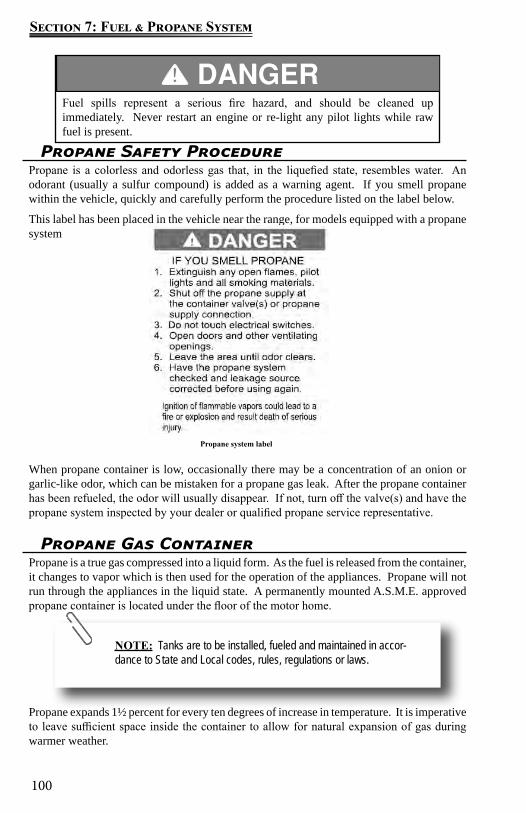
100
Section 7: Fuel & Propane System
Propane Safety ProcedurePropane is a colorless and odorless gas that, in the liquefied state, resembles water. An odorant (usually a sulfur compound) is added as a warning agent. If you smell propane within the vehicle, quickly and carefully perform the procedure listed on the label below.
This label has been placed in the vehicle near the range, for models equipped with a propane system
When propane container is low, occasionally there may be a concentration of an onion or garlic-like odor, which can be mistaken for a propane gas leak. After the propane container has been refueled, the odor will usually disappear. If not, turn off the valve(s) and have the propane system inspected by your dealer or qualified propane service representative.
Fuel spills represent a serious fire hazard, and should be cleaned up immediately. Never restart an engine or re-light any pilot lights while raw fuel is present.
Propane system label
Propane Gas Container Propane is a true gas compressed into a liquid form. As the fuel is released from the container, it changes to vapor which is then used for the operation of the appliances. Propane will not run through the appliances in the liquid state. A permanently mounted A.S.M.E. approved propane container is located under the floor of the motor home.
Propane expands 1½ percent for every ten degrees of increase in temperature. It is imperative to leave sufficient space inside the container to allow for natural expansion of gas during warmer weather.
NOTE: Tanks are to be installed, fueled and maintained in accor-dance to State and Local codes, rules, regulations or laws.
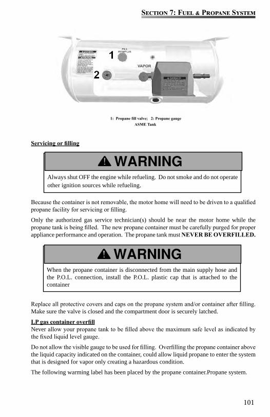
101
Section 7: Fuel & Propane System
Servicing or filling
Because the container is not removable, the motor home will need to be driven to a qualified propane facility for servicing or filling.
Only the authorized gas service technician(s) should be near the motor home while the propane tank is being filled. The new propane container must be carefully purged for proper appliance performance and operation. The propane tank must NEVER BE OVERFILLED.
Replace all protective covers and caps on the propane system and/or container after filling. Make sure the valve is closed and the compartment door is securely latched.
LP gas container overfillNever allow your propane tank to be filled above the maximum safe level as indicated by the fixed liquid level gauge.
Do not allow the visible gauge to be used for filling. Overfilling the propane container above the liquid capacity indicated on the container, could allow liquid propane to enter the system that is designed for vapor only creating a hazardous condition.
The following warming label has been placed by the propane container.Propane system.
ASME Tank1: Propane fill valve; 2: Propane gauge
Always shut OFF the engine while refueling. Do not smoke and do not operate other ignition sources while refueling.
When the propane container is disconnected from the main supply hose and the P.O.L. connection, install the P.O.L. plastic cap that is attached to the container
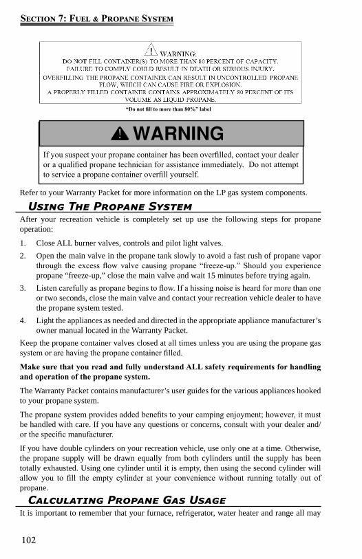
102
Section 7: Fuel & Propane System
If you suspect your propane container has been overfilled, contact your dealer or a qualified propane technician for assistance immediately. Do not attempt to service a propane container overfill yourself.
“Do not fill to more than 80%” label
Using The Propane SystemAfter your recreation vehicle is completely set up use the following steps for propane operation:
1. Close ALL burner valves, controls and pilot light valves.2. Open the main valve in the propane tank slowly to avoid a fast rush of propane vapor
through the excess flow valve causing propane “freeze-up.” Should you experience propane “freeze-up,” close the main valve and wait 15 minutes before trying again.
3. Listen carefully as propane begins to flow. If a hissing noise is heard for more than one or two seconds, close the main valve and contact your recreation vehicle dealer to have the propane system tested.
4. Light the appliances as needed and directed in the appropriate appliance manufacturer’s owner manual located in the Warranty Packet.
Keep the propane container valves closed at all times unless you are using the propane gas system or are having the propane container filled.
Make sure that you read and fully understand ALL safety requirements for handling and operation of the propane system.
The Warranty Packet contains manufacturer’s user guides for the various appliances hooked to your propane system.
The propane system provides added benefits to your camping enjoyment; however, it must be handled with care. If you have any questions or concerns, consult with your dealer and/or the specific manufacturer.
If you have double cylinders on your recreation vehicle, use only one at a time. Otherwise, the propane supply will be drawn equally from both cylinders until the supply has been totally exhausted. Using one cylinder until it is empty, then using the second cylinder will allow you to fill the empty cylinder at your convenience without running totally out of propane.
Calculating Propane Gas UsageIt is important to remember that your furnace, refrigerator, water heater and range all may
Refer to your Warranty Packet for more information on the LP gas system components.
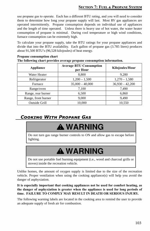
103
Section 7: Fuel & Propane System
Cooking With Propane Gas
Unlike homes, the amount of oxygen supply is limited due to the size of the recreation vehicle. Proper ventilation when using the cooking appliance(s) will help you avoid the danger of asphyxiation.
It is especially important that cooking appliances not be used for comfort heating, as the danger of asphyxiation is greater when the appliance is used for long periods of time. FAILURE TO COMPLY MAY RESULT IN DEATH OR SERIOUS INJURY.
The following warning labels are located in the cooking area to remind the user to provide an adequate supply of fresh air for combustion.
Do not turn gas range burner controls to ON and allow gas to escape before lighting.
Do not use portable fuel burning equipment (i.e., wood and charcoal grills or stoves) inside the recreation vehicle.
use propane gas to operate. Each has a different BTU rating, and you will need to consider them to determine how long your propane supply will last. Most RV gas appliances are operated intermittently. Propane consumption depends on individual use of appliances and the length of time operated. Unless there is heavy use of hot water, the water heater consumption of propane is minimal. During cool temperature or high wind conditions, furnace consumption can be extremely high.
To calculate your propane supply, take the BTU ratings for your propane appliances and divide that into the BTU availability. Each gallon of propane gas (3.785 liters) produces about 91,500 BTU’s (96,528 kilojoules) of heat energy.
Propane consumption chartThe following chart provides average propane consumption information.
Appliance Average BTU Consumption per Hour Kilojoules/Hour
Water Heater 8,800 9,280Refrigerator 1,200 – 1,500 1,270 – 1,580
Furnace 35,000 – 40,000 36,930 – 42,200Range/oven 7,100 7,490
Range, rear burner 6,500 6,860Range, front burner 9,000 9,490
Outside Grill 10,000 10,550
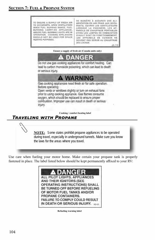
104
Section 7: Fuel & Propane System
Traveling with Propane
Use care when fueling your motor home. Make certain your propane tank is properly fastened in place. The label listed below should be kept permanently affixed to your RV:
Ensure a supply of fresh air (Canada units only)
Cooking / comfort heating label
NOTE: Some states prohibit propane appliances to be operated during travel, especially in underground tunnels. Make sure you know the laws for the areas where you travel.
Refueling warning label
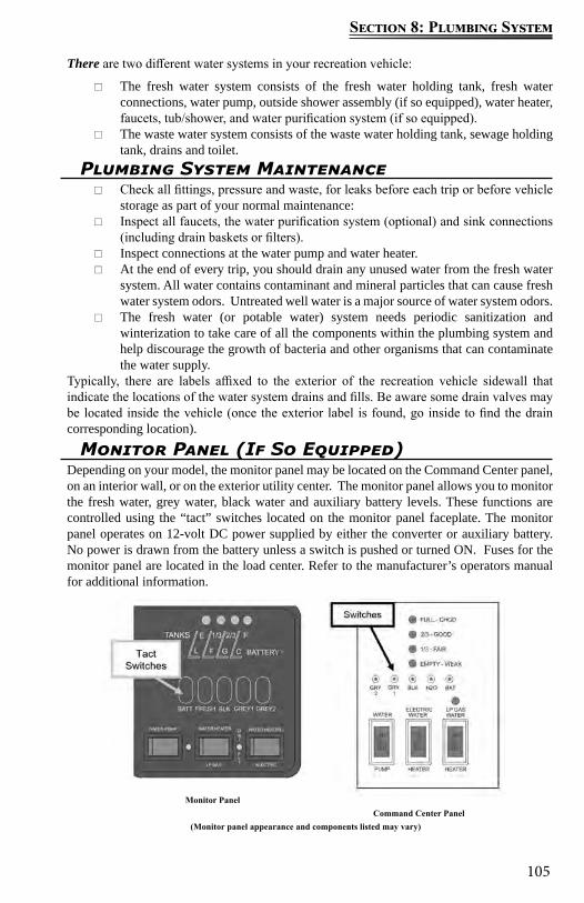
105
Section 8: Plumbing System
There are two different water systems in your recreation vehicle:
The fresh water system consists of the fresh water holding tank, fresh water connections, water pump, outside shower assembly (if so equipped), water heater, faucets, tub/shower, and water purification system (if so equipped).
The waste water system consists of the waste water holding tank, sewage holding tank, drains and toilet.
Plumbing System Maintenance Check all fittings, pressure and waste, for leaks before each trip or before vehicle
storage as part of your normal maintenance: Inspect all faucets, the water purification system (optional) and sink connections
(including drain baskets or filters). Inspect connections at the water pump and water heater. At the end of every trip, you should drain any unused water from the fresh water
system. All water contains contaminant and mineral particles that can cause fresh water system odors. Untreated well water is a major source of water system odors.
The fresh water (or potable water) system needs periodic sanitization and winterization to take care of all the components within the plumbing system and help discourage the growth of bacteria and other organisms that can contaminate the water supply.
Typically, there are labels affixed to the exterior of the recreation vehicle sidewall that indicate the locations of the water system drains and fills. Be aware some drain valves may be located inside the vehicle (once the exterior label is found, go inside to find the drain corresponding location).
Monitor Panel (If So Equipped)Depending on your model, the monitor panel may be located on the Command Center panel, on an interior wall, or on the exterior utility center. The monitor panel allows you to monitor the fresh water, grey water, black water and auxiliary battery levels. These functions are controlled using the “tact” switches located on the monitor panel faceplate. The monitor panel operates on 12-volt DC power supplied by either the converter or auxiliary battery. No power is drawn from the battery unless a switch is pushed or turned ON. Fuses for the monitor panel are located in the load center. Refer to the manufacturer’s operators manual for additional information.
Monitor PanelCommand Center Panel
(Monitor panel appearance and components listed may vary)
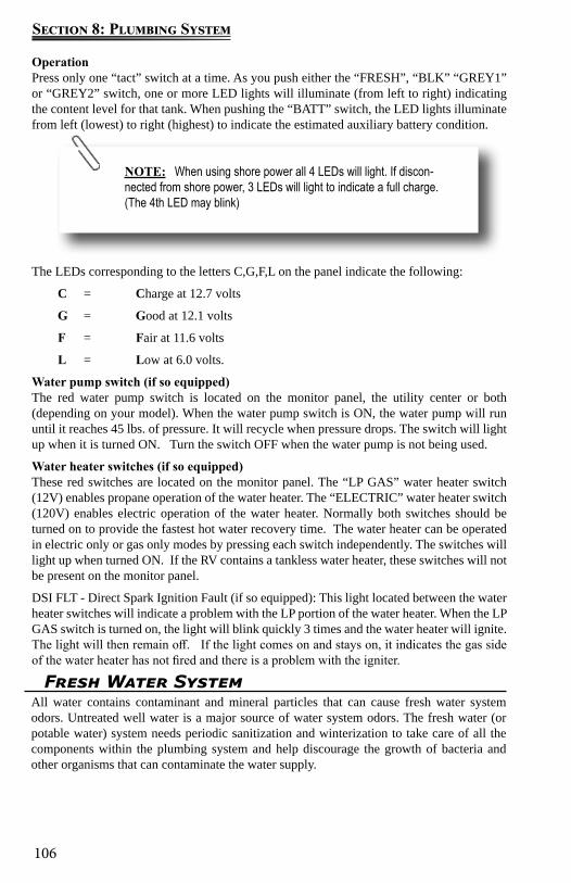
106
Section 8: Plumbing System
Fresh Water SystemAll water contains contaminant and mineral particles that can cause fresh water system odors. Untreated well water is a major source of water system odors. The fresh water (or potable water) system needs periodic sanitization and winterization to take care of all the components within the plumbing system and help discourage the growth of bacteria and other organisms that can contaminate the water supply.
OperationPress only one “tact” switch at a time. As you push either the “FRESH”, “BLK” “GREY1” or “GREY2” switch, one or more LED lights will illuminate (from left to right) indicating the content level for that tank. When pushing the “BATT” switch, the LED lights illuminate from left (lowest) to right (highest) to indicate the estimated auxiliary battery condition.
The LEDs corresponding to the letters C,G,F,L on the panel indicate the following:
C = Charge at 12.7 volts
G = Good at 12.1 volts
F = Fair at 11.6 volts
L = Low at 6.0 volts.
Water pump switch (if so equipped)The red water pump switch is located on the monitor panel, the utility center or both (depending on your model). When the water pump switch is ON, the water pump will run until it reaches 45 lbs. of pressure. It will recycle when pressure drops. The switch will light up when it is turned ON. Turn the switch OFF when the water pump is not being used.
Water heater switches (if so equipped)These red switches are located on the monitor panel. The “LP GAS” water heater switch (12V) enables propane operation of the water heater. The “ELECTRIC” water heater switch (120V) enables electric operation of the water heater. Normally both switches should be turned on to provide the fastest hot water recovery time. The water heater can be operated in electric only or gas only modes by pressing each switch independently. The switches will light up when turned ON. If the RV contains a tankless water heater, these switches will not be present on the monitor panel.
DSI FLT - Direct Spark Ignition Fault (if so equipped): This light located between the water heater switches will indicate a problem with the LP portion of the water heater. When the LP GAS switch is turned on, the light will blink quickly 3 times and the water heater will ignite. The light will then remain off. If the light comes on and stays on, it indicates the gas side of the water heater has not fired and there is a problem with the igniter.
NOTE: When using shore power all 4 LEDs will light. If discon-nected from shore power, 3 LEDs will light to indicate a full charge. (The 4th LED may blink)
107
Section 8: Plumbing System
Fresh Water Holding TankThere may be several ways to fill the fresh water tank depending on the model. For details of each method, refer to the Fresh Water Connections or the Utility Center (if so equipped) sections. There are plastic overflow tubes plumbed into the fresh water holding tank which allow water to flow out of the water tank (see City Water Fill). Occasionally, you may see water coming from the overflow tubes when the fresh water holding tank is filled. This is normal and can be a result of the recreation vehicle being parked on an incline, or the motion caused by starting or stopping during travel.
DO NOT drink water deemed microbiologically unsafe or of unknown quality..
Never travel with full fresh, black or grey water holding tanks..
Be careful not to overfill the fresh water holding tank. It can pressurize the tank, causing leakage and water damage and void the warranty. DO NOT leave the tank unattended while filling.
Do not cap, block or modify the fresh water tank overflow tubes in any way. Enough water pressure can build up during the filling process to damage the plumbing system if the overflow tubes are obstructed.
12-Volt Water Pump & SwitchWhen you want to use water in your recreation vehicle and it is not hooked up to city water, you will need sufficient 12-volt DC power to run the water pump. Once activated, the water pump (also known as the demand pump) will self-prime, and provide water. The pump is designed for intermittent use only. Using the pump continuously or with high pressure will shorten the life of the pump and is not covered in your warranty. The water pump is engineered with a check valve to prevent water from back flowing into the fresh water supply tank.
Periodically check the in-line water pump strainer for accumulated debris. To clean, shut off the water pump, unscrew the clear cap, remove the re-useable metal strainer and clear any debris, then reinstall.
For additional information on the care and operation of the pump, read the safety and operating information in the pump manufacturer’s owner’s manual.
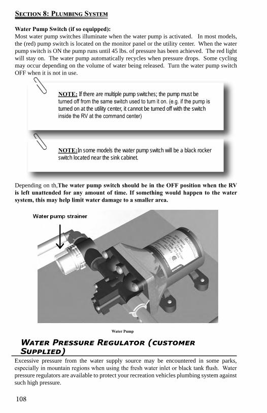
108
Section 8: Plumbing System
Water Pump Switch (if so equipped): Most water pump switches illuminate when the water pump is activated. In most models, the (red) pump switch is located on the monitor panel or the utility center. When the water pump switch is ON the pump runs until 45 lbs. of pressure has been achieved. The red light will stay on. The water pump automatically recycles when pressure drops. Some cycling may occur depending on the volume of water being released. Turn the water pump switch OFF when it is not in use.
Depending on th,The water pump switch should be in the OFF position when the RV is left unattended for any amount of time. If something would happen to the water system, this may help limit water damage to a smaller area.
Water Pump
NOTE:In some models the water pump switch will be a black rocker switch located near the sink cabinet.
NOTE: If there are multiple pump switches; the pump must be turned off from the same switch used to turn it on. (e.g. if the pump is turned on at the utility center, it cannot be turned off with the switch inside the RV at the command center)
Water Pressure Regulator (customer Supplied)
Excessive pressure from the water supply source may be encountered in some parks, especially in mountain regions when using the fresh water inlet or black tank flush. Water pressure regulators are available to protect your recreation vehicles plumbing system against such high pressure.

109
Section 8: Plumbing System
Utility CenterThe following information defines the function of the utility center water valve settings indicated on the utility center label:
City Fixtures - Allows you to access water from all faucets using a pressurized water source (referred to from here on as “city water”).
City Fill Tank - Allows you to fill your fresh water tank using city water. Country Fill - Allows you to siphon fill your fresh water tank (using the 12-volt water
pump) when you do not have access to city water. Normal - If the RV is not connected to city water, this setting allows you to pump water
from the fresh water tank to all faucets using the 12-volt water pump. Sanitize/Winterize Lines – Allows you to sanitize or winterize the water lines in your
motor home. Sanitize Tank – Allows you to sanitize the fresh water tank.
Depending on your model, the city water connections may be configured one of three ways:
1. A water valve control panel (Fig A). The City Water Connection inlet will be located on the outside of the motor home. The pump switch will be located inside the motor home on the Monitor Panel.
2. A horizontal utility center (Fig B). This utility center contains the city water connection inlet, pump switch, water valve controls, outside shower, black tank flush inlet and a macerator discharge system.
3. A vertical utility center (Fig C). This utility center contains an outside shower, city water connection inlet, black tank flush inlet, pump switch and water valve controls.
A water pressure regulator is recommended to prevent damage to the plumbing system or components. To prevent damage when using the city water connection, a 45 lb. (315 KPa) rated water pressure regulator is recommended.
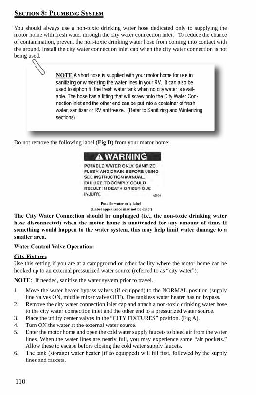
110
Section 8: Plumbing System
You should always use a non-toxic drinking water hose dedicated only to supplying the motor home with fresh water through the city water connection inlet. To reduce the chance of contamination, prevent the non-toxic drinking water hose from coming into contact with the ground. Install the city water connection inlet cap when the city water connection is not being used.
Do not remove the following label (Fig D) from your motor home:
The City Water Connection should be unplugged (i.e., the non-toxic drinking water hose disconnected) when the motor home is unattended for any amount of time. If something would happen to the water system, this may help limit water damage to a smaller area.
Water Control Valve Operation:
City FixturesUse this setting if you are at a campground or other facility where the motor home can be hooked up to an external pressurized water source (referred to as “city water”).
NOTE: If needed, sanitize the water system prior to travel.
1. Move the water heater bypass valves (if equipped) to the NORMAL position (supply line valves ON, middle mixer valve OFF). The tankless water heater has no bypass.
2. Remove the city water connection inlet cap and attach a non-toxic drinking water hose to the city water connection inlet and the other end to a pressurized water source.
3. Place the utility center valves in the “CITY FIXTURES” position. (Fig A).4. Turn ON the water at the external water source.5. Enter the motor home and open the cold water supply faucets to bleed air from the water
lines. When the water lines are nearly full, you may experience some “air pockets.” Allow these to escape before closing the cold water supply faucets.
6. The tank (storage) water heater (if so equipped) will fill first, followed by the supply lines and faucets.
NOTE A short hose is supplied with your motor home for use in sanitizing or winterizing the water lines in your RV. It can also be used to siphon fill the fresh water tank when no city water is avail-able. The hose has a fitting that will screw onto the City Water Con-nection inlet and the other end can be put into a container of fresh water, sanitizer or RV antifreeze. (Refer to Sanitizing and Winterizing sections)
Potable water only label(Label appearance may not be exact)
111
Section 8: Plumbing System
7. Turn the appropriate (12-volt GAS or 120-volt ELECTRIC) storage water heater power switch ON. (For a tankless water heater (if so equipped) turn the water heater power switch ON (the switch is located outside the RV at the water heater panel). The water will be heated on demand.
To disconnect8. Shut OFF the water at the external water source and disconnect the hose.9. Disconnect the non-toxic drinking water hose from the city water connection inlet and
reinstall the city water connection inlet cap.City Fill TankUse this setting to fill the water tank from a pressurized water source.
NOTE: If needed, sanitize the water system prior to travel.
1. If equipped with a tank (storage) water heater, set the bypass valves to the NORMAL position (supply line valves ON, middle mixer valve OFF). The tankless water heater has no bypass valves.
2. Remove the city water connection inlet cap. Attach a non-toxic water hose to the city water connection and the other end to a pressurized water source.
3. Place the utility center valves in the “CITY FILL TANK” position (Fig A).4. Turn ON the water at the external water source.5. Water will flow into the fresh water tank.During the filling process, periodically check the fresh water tank level using the monitor panel located in the command center. When the fresh water tank is full, it is normal to see water running from the fresh water overflow tubes onto the ground.
To disconnect6. Shut OFF the water at the external water source.7. Disconnect the non-toxic drinking water hose and reinstall the city water connection
inlet cap.Country FillThis setting is used to siphon fill the water tank from a water container when dry camping and a pressurized water source is unavailable.
NOTE: If needed, sanitize the water system prior to travel.
1. If equipped with a tank (storage) water heater, set the bypass valves to the NORMAL position (supply line valves ON, middle mixer valve OFF). The tankless water heater has no bypass valves.
2. Remove the city water connection inlet cap and attach one end of the short hose supplied with the motor home to the city water connection inlet, and the other end into a container of fresh water.
3. Place the utility center valves in the “COUNTRY FILL” position. (Fig A)4. Turn water pump ON. Water should begin to be drawn out of the container and into the
fresh water tank. To aid siphoning place the container on a flat surface approximately 2 feet off the ground. All low point drains must be off in order to create a siphon.
During the filling process, periodically check the fresh water tank level using the monitor panel located in the command center. When the fresh water tank is full, it is normal to see water running from the fresh water overflow tubes onto the ground.
To disconnect5. Shut OFF the water pump.6. Disconnect the short water hose and reinstall the city water connection inlet cap.
112
Section 8: Plumbing System
NOTE:Filters should be replaced at the beginning of each camping season or if they have come into contact with contaminated water.
NOTE:When not in use, the water filter cartridge should be stored out of freezing temperatures. RV antifreeze will damage the water filter cartridge.
Normal SettingThis setting allows you to use the water system when dry camping. The water pump circulates water from the fresh water tank to all the fixtures.
NOTE: If needed, sanitize the water system prior to travel.
1. If equipped with a tank (storage) water heater, set the bypass valves to the NORMAL position (supply line valves ON, middle mixer valve OFF). The tankless water heater has no bypass valves.
2. Place the utility center valves in the “NORMAL” position (Fig A).3. Turn the water pump ON (make sure you have sufficient 12-volt power).4. Water will be pumped from the fresh water tank to all faucets.5. The tank (storage) water heater will fill first, followed by the supply lines and faucets.6. Enter the motor home and open the cold water supply faucets to bleed air from the
water lines. When the water lines are nearly full, you may experience some “air pockets.” Allow these to escape before closing the cold water supply faucets.
7. Turn the appropriate (12-volt GAS or 120-volt ELECTRIC) storage water heater power switch ON. For a tankless water heater (if so equipped) turn the water heater power switch ON (switch is located outside the RV at the water heater panel) Water will be heated on demand.
Sanitize TankThis setting is used to sanitize the fresh water tank. When the fresh water tank drain and the low point drains are closed, a siphon is created in the water lines allowing sanitizer to be pulled into the fresh water tank from an external container (see Sanitization section).Sanitize / Winterize LinesThis setting is typically used for drawing RV antifreeze into the water lines of the motor home. When the fresh water tank drain and the low point drains are closed, a siphon is created in the water lines allowing antifreeze to be pulled into the water lines. This setting will not allow antifreeze into the fresh water tank (see Winterization section).
Water Purification System (If So Equipped)Depending on the model, your recreation vehicle may have a canister style water purification system. If the water supply has not been used for some time, allow the water to flow for several minutes to flush the system.
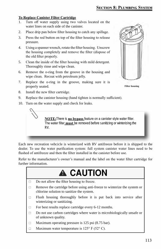
113
Section 8: Plumbing System
To Replace Canister Filter Cartridge1. Turn off water supply using two valves located on the
water lines on each side of the canister.2. Place drip pan below filter housing to catch any spillage.3. Press the red button on top of the filter housing to release
pressure.4. Using a spanner wrench, rotate the filter housing. Unscrew
the housing completely and remove the filter (dispose of the old filter properly.
5. Clean the inside of the filter housing with mild detergent. Thoroughly rinse and wipe clean.
6. Remove the o-ring from the groove in the housing and wipe clean. Recoat with petroleum jelly.
7. Replace the o-ring in the groove, making sure it is properly seated.
8. Install the new filter cartridge.9. Replace the canister housing (hand tighten is normally sufficient).10. Turn on the water supply and check for leaks.
Each new recreation vehcicle is winterized with RV antifreeze before it is shipped to the dealer. To use the water purification system: full system canister water lines need to be flushed of antifreeze and then the filter installed in the canister before use.
Refer to the manufacturer’s owner’s manual and the label on the water filter cartridge for further information.
Filter housing
Do not allow the filter housing to freeze. Remove the cartridge before using anti-freeze to winterize the system or
chlorine solution to sanitize the system. Flush housing thoroughly before it is put back into service after
winterizing or sanitizing. For best results replace cartridge every 6-12 months. Do not use carbon cartridges where water is microbiologically unsafe or
of unknown quality. Maximum operating pressure is 125 psi (8.75 bar). Maximum water temperature is 125° F (52° C).
NOTE:There is no bypass feature on a canister style water filter. The water filter must be removed before sanitizing or winterizing the RV.
114
Section 8: Plumbing System
Water Heater
Operating Instructions
Your motor home may be equipped with either a tank (storage) water heater or tankless water heater. The following is an overview of both systems. For detailed operating instructions, refer to the manufacturer’s owner’s manual supplied in your Warranty packet.
Tank (Storage) Water Heater System(If So Equipped)Gas/Electric DSI Tank (Storage) Water Heater (If So Equipped)Your motor home may be equipped with a gas/electric DSI (direct spark ignite) water heater. The following is an overview of the water heater operation. For detailed operating and safety information, refer to the manufacturer’s user’s guide included in the Owner’s Warranty packet.
Read the safety and operating information provided in the manufacturer’s user guide before attempting to activate the water heater. Make sure the water heater is filled with water before use; even momentary operation of the water heater without water in it may result in damage to the tank and/or controls. Always open both the hot and cold water faucets when filling the fresh water tank to allow air pockets to be forced out of the water heater.
Hydrogen gas may result if you have not used the water heater for two weeks or more. HYDROGEN GAS IS EXTREMELY FLAMMABLE. To reduce the risk of injury under these conditions, open the hot water faucet for several minutes at the kitchen sink before you use any electrical appliance connected to the hot water system. If hydrogen is present, you may hear what sounds like air escaping through the pipe as the water begins to flow. Hydrogen gas may be present even after water has been drained from the water heater tank. Open the faucet at the sink and allow the system to vent for five to ten minutes. Do not smoke or have any open flame near the open faucet while venting. On DSI water heater models, make sure the switch is OFF.
Do not alter the operation or change the design/construction of your water heater. For your safety, only factory authorized parts should be used on your water heater. Accessories marketed for recreation vehicles, such as an “add-on” electric heating elements, are not recommended by the manufacturer. Such items are not approved to be installed and could create an unsafe condition and will void all warranties
If you smell propane gas then STOP! and follow the procedures listed in the Propane System Section before attempting to operate the water heater.
115
Section 8: Plumbing System
The DSI water heater is designed to heat water quickly and efficiently. The water heater manufacturer has preset the sensing limit to maintain the water temperature when the water heater is activated. The thermostat on your water heater is not adjustable. It is a temperature sensing limit designed to maintain a water temperature of 130°F (54°C).
The water heater does not have a pilot. It is equipped with an ignition device which automatically lights the burner. Do not try to light the burner by hand.
Operating instructions1. Turn OFF all electric power to the water heater.2. Turn OFF the propane supply.3. Wait five minutes for the propane to clear the area. If you smell propane STOP!
Follow the safety instructions listed in the manufacturer’s owner’s manual. If you do not smell propane, go to the next step.
4. Turn ON the propane supply.5. Turn ON electrical power to the water heater.6. Turn the switch to the “ON” position. If the burner does not light, the system will
automatically attempt two more tries for ignition before lock-out occurs. NOTE: Each ignition cycle will have a 15 second purge before spark cycle if system is a three try system.
7. If lock-out occurs before the main burner lights, turn the water heater control switch to OFF, wait five seconds and turn the switch to the ON position. This will restart the ignition cycle.
8. The first start-up of the heater may require several ignition cycles before all the air is purged form the propane lines.
If the burner will not come on, the following items should be checked before calling a service person:
1. See if the switch is turned OFF.2. Check to make sure the propane supply to the water heater is not empty or turned OFF.3. Check to see if the reset button on the water heater ECO is tripped.Water heater bypass (If So Equipped)Your motor home may be equipped with a water heater bypass. This three-valve system is located at either the water heater, or on the utility center panel depending on your model. For detailed information see the Water Heater Bypass section
Odor from the hot water systemMany water supplies contain sufficient amounts of sulfur to produce an odor, often called “sulfur water.” Sulfur water can be caused by a chemical action or by bacteria. Generally, sulfur water is not harmful, only unpleasant to smell. Refer to the water heater manufacturer’s owner’s manual for details on eliminating the odor from sulfur water. Odor from sulfur water is not a service problem.
Do not replace anode rod or any other component with an accessory part that is not authorized by the water heater manufacturer, such as an “add-on electric heating element. Such items are not approved to be installed and could create an unsafe condition and will void all warranties
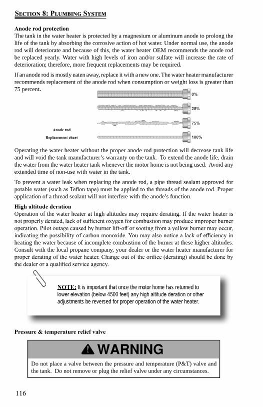
116
Section 8: Plumbing System
Anode rod
Replacement chart
NOTE: It is important that once the motor home has returned to lower elevation (below 4500 feet) any high altitude deration or other adjustments be reversed for proper operation of the water heater.
Do not place a valve between the pressure and temperature (P&T) valve and the tank. Do not remove or plug the relief valve under any circumstances.
Anode rod protectionThe tank in the water heater is protected by a magnesium or aluminum anode to prolong the life of the tank by absorbing the corrosive action of hot water. Under normal use, the anode rod will deteriorate and because of this, the water heater OEM recommends the anode rod be replaced yearly. Water with high levels of iron and/or sulfate will increase the rate of deterioration; therefore, more frequent replacements may be required.
If an anode rod is mostly eaten away, replace it with a new one. The water heater manufacturer recommends replacement of the anode rod when consumption or weight loss is greater than 75 percent.
Operating the water heater without the proper anode rod protection will decrease tank life and will void the tank manufacturer’s warranty on the tank. To extend the anode life, drain the water from the water heater tank whenever the motor home is not being used. Avoid any extended time of non-use with water in the tank.
To prevent a water leak when replacing the anode rod, a pipe thread sealant approved for potable water (such as Teflon tape) must be applied to the threads of the anode rod. Proper application of a thread sealant will not interfere with the anode’s function.
High altitude derationOperation of the water heater at high altitudes may require derating. If the water heater is not properly derated, lack of sufficient oxygen for combustion may produce improper burner operation. Pilot outage caused by burner lift-off or sooting from a yellow burner may occur, indicating the possibility of carbon monoxide. You may also notice a lack of efficiency in heating the water because of incomplete combustion of the burner at these higher altitudes. Consult with the local propane company, your dealer or the water heater manufacturer for proper derating of the water heater. Change out of the orifice (derating) should be done by the dealer or a qualified service agency.
Pressure & temperature relief valve
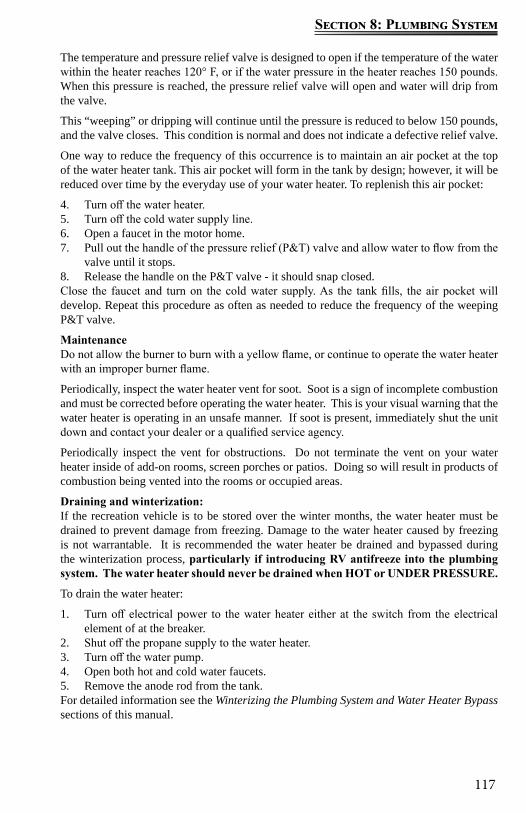
117
Section 8: Plumbing System
The temperature and pressure relief valve is designed to open if the temperature of the water within the heater reaches 120° F, or if the water pressure in the heater reaches 150 pounds. When this pressure is reached, the pressure relief valve will open and water will drip from the valve.
This “weeping” or dripping will continue until the pressure is reduced to below 150 pounds, and the valve closes. This condition is normal and does not indicate a defective relief valve.
One way to reduce the frequency of this occurrence is to maintain an air pocket at the top of the water heater tank. This air pocket will form in the tank by design; however, it will be reduced over time by the everyday use of your water heater. To replenish this air pocket:
4. Turn off the water heater.5. Turn off the cold water supply line.6. Open a faucet in the motor home.7. Pull out the handle of the pressure relief (P&T) valve and allow water to flow from the
valve until it stops.8. Release the handle on the P&T valve - it should snap closed. Close the faucet and turn on the cold water supply. As the tank fills, the air pocket will develop. Repeat this procedure as often as needed to reduce the frequency of the weeping P&T valve.
MaintenanceDo not allow the burner to burn with a yellow flame, or continue to operate the water heater with an improper burner flame.
Periodically, inspect the water heater vent for soot. Soot is a sign of incomplete combustion and must be corrected before operating the water heater. This is your visual warning that the water heater is operating in an unsafe manner. If soot is present, immediately shut the unit down and contact your dealer or a qualified service agency.
Periodically inspect the vent for obstructions. Do not terminate the vent on your water heater inside of add-on rooms, screen porches or patios. Doing so will result in products of combustion being vented into the rooms or occupied areas.
Draining and winterization:If the recreation vehicle is to be stored over the winter months, the water heater must be drained to prevent damage from freezing. Damage to the water heater caused by freezing is not warrantable. It is recommended the water heater be drained and bypassed during the winterization process, particularly if introducing RV antifreeze into the plumbing system. The water heater should never be drained when HOT or UNDER PRESSURE.
To drain the water heater:
1. Turn off electrical power to the water heater either at the switch from the electrical element of at the breaker.
2. Shut off the propane supply to the water heater.3. Turn off the water pump.4. Open both hot and cold water faucets.5. Remove the anode rod from the tank.For detailed information see the Winterizing the Plumbing System and Water Heater Bypass sections of this manual.

118
Section 8: Plumbing System
TANKLESS WATER HEATER (If So Equipped)Your motor home may be equipped with a tankless water heater. The tankless water heater uses less LP Gas than storage tank model water heaters since it only uses energy when hot water is demanded. There is no pilot light to burn when no hot water is needed. The tankless water heater supplies an unlimited supply of hot water on demand (once lines are purged of standing water). As hot water is used, the cold water enters the heater. A water flow sensor detects the flowing water and automatically ignites the burner. Water circulates through the heat exchanger and is heated to the set temperature. When the tap is closed, the unit shuts down.
The tankless water heater does not require an anode rod to prevent corrosion, or a by-pass valve for winterizing. It is not affected by high altitudes.
The output temperature of the water depends on the temperature of the inlet water AND the amount of hot water that is drawn. If the inlet water temperature is over 65ºF the tankless water heater will generate water in the range of 105°F to 120°F (on Low flame) depending on the water flow selected by the user.
Operating Tips Purge air out of ALL hot and cold water lines. Open the water heater door and turn the power switch “ON”. Set GMC (gas modulator dial) to appropriate setting.
● Normal weather – set dial to the middle area. ● Extreme cold weather – set dial to the extreme right (large flame). ● Extreme hot weather – set dial to the extreme left (small flame).
Open hot water faucet to a medium water flow. It may take a few seconds for the water to travel from the water heater to the faucet.
To reduce temperature: ● Turn GMC dial “counter-clockwise”. ● Increase hot water flow. ● Gradually add cold water.
To increase temperature: ● Turn GMC dial “clockwise”. NOTE: Use caution not to increase the dial too
much which could cause the hot water temperature to rise to the point the water heater “limits’ and turns OFF the flame (flame shut off is approximately 131° F).
● Reduce hot water flow.For Additional Information For detailed operating information refer to the manufacturer’s owner’s manual included in the Warranty Packet.
WinterizationFreezing of the water heater and its plumbing components will result in severe damage not covered by warranty. For this reason it is advisable to follow the recommendation(s) below if the unit is to be stored in a freezing environment or for long periods of time. At the start of the winter season or before traveling to a location where freezing conditions are likely, the unit must be winterized.
The very small amount of water present in the heat exchanger DOES NOT require the installation of a bypass kit. Winterization can be accomplished using one of the two
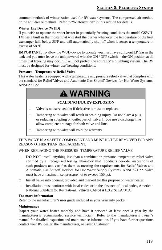
119
Section 8: Plumbing System
SCALDING INJURY-EXPLOSION
Valve is not serviceable; if defective it must be replaced.
Tampering with valve will result in scalding injury. Do not place a plug or reducing coupling on outlet part of valve. If you use a discharge line allow complete drainage for both valve and line.
Tampering with valve will void the warranty.
common methods of winterization used for RV water systems, The compressed air method or the anti-freeze method. Refer to “Winterization” in this section for details.
Winter Use Device (WUD)If you wish to operate the water heater in potentially freezing conditions the model GSWH-1M has a built in thermostat that will start the burner whenever the temperature of the heat exchanger falls below 38ºF and will automatically shut off when it senses a temperature in excess of 58 ºF.
IMPORTANT: To allow the WUD device to operate you must have sufficient LP Gas in the tank and you must leave the unit powered with the ON / OFF switch in the ON position at all times that freezing may occur. It will not protect the entire RV’s plumbing system. The RV must be designed for winter use/freezing conditions.
Pressure - Temperature Relief ValveThis water heater is equipped with a temperature and pressure relief valve that complies with the standard for Relief Valves and Automatic Gas Shutoff Devices for Hot Water Systems, ANSI Z21.22.
THIS VALVE IS A SAFETY COMPONENT AND MUST NOT BE REMOVED FOR ANY REASON OTHER THAN REPLACEMENT.
WHEN REPLACING THE PRESSURE–TEMPERATURE RELIEF VALVE
DO NOT install anything less than a combination pressure–temperature relief valve certified by a recognized testing laboratory that conducts periodic inspections of such products and certifies them as meeting the requirements for Relief Valves and Automatic Gas Shutoff Devices for Hot Water Supply Systems, ANSI Z21.22. Valve must have a maximum set pressure not to exceed 150 psi.
Install valve into opening provided and marked for this purpose on water heater. Installation must conform with local codes or in the absence of local codes, American
National Standard for Recreational Vehicles, ANSI A119.2/NFPA 501C.For more informationRefer to the manufacturer’s user guide included in your Warranty packet.
MaintenanceInspect your water heater monthly and have it serviced at least once a year by the manufacturer’s recommended service technician. Refer to the manufacturer’s owner’s manual for detailed inspection and maintenance information. If you have further questions contact your RV dealer, the manufacturer, or Jayco Customer
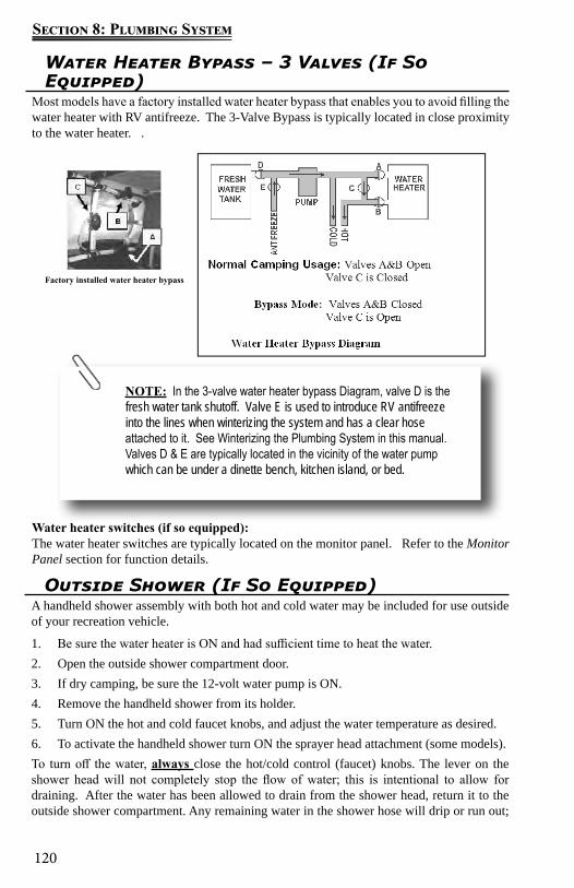
120
Section 8: Plumbing System
Water Heater Bypass – 3 Valves (If So Equipped)
Most models have a factory installed water heater bypass that enables you to avoid filling the water heater with RV antifreeze. The 3-Valve Bypass is typically located in close proximity to the water heater. .
Water heater switches (if so equipped):The water heater switches are typically located on the monitor panel. Refer to the Monitor Panel section for function details.
Factory installed water heater bypass
NOTE: In the 3-valve water heater bypass Diagram, valve D is the fresh water tank shutoff. Valve E is used to introduce RV antifreeze into the lines when winterizing the system and has a clear hose attached to it. See Winterizing the Plumbing System in this manual. Valves D & E are typically located in the vicinity of the water pump which can be under a dinette bench, kitchen island, or bed.
Outside Shower (If So Equipped)A handheld shower assembly with both hot and cold water may be included for use outside of your recreation vehicle.
1. Be sure the water heater is ON and had sufficient time to heat the water.2. Open the outside shower compartment door. 3. If dry camping, be sure the 12-volt water pump is ON.4. Remove the handheld shower from its holder.5. Turn ON the hot and cold faucet knobs, and adjust the water temperature as desired.6. To activate the handheld shower turn ON the sprayer head attachment (some models).To turn off the water, always close the hot/cold control (faucet) knobs. The lever on the shower head will not completely stop the flow of water; this is intentional to allow for draining. After the water has been allowed to drain from the shower head, return it to the outside shower compartment. Any remaining water in the shower hose will drip or run out;
121
Section 8: Plumbing System
NOTE: The shower head may be removed from the hose so that it will drain faster. If you remove the shower head, be sure to reas-semble it prior to storage.
NOTE: When putting the shower assembly back into the storage compartment, make sure the hose is not pinched or the shower head is positioned in a way it can be damaged.
this is not a leak but performs as intended. If you are dry camping, turn the water pump OFF.
Turning off the water with the shower head lever can also create a condition where the hot and cold water will mix through the outside shower faucet, thereby reducing the temperature of the hot water. It can appear as though the hot water heater is not working properly.
Bathroom Tub / Shower The shower faucet includes a vacuum breaker for the shower. There are two purposes for this breaker:
To prevent siphoning water through the hose from another fixture. To prevent water from being retained in the hose.
The showerhead DOES NOT have a complete shut-off valve (the complete shut-off is at the faucet). The showerhead may drip slightly in the OFF position after use; this is normal and does not indicate a leak or defect.
There may be air in the plumbing lines that will need to be bled out before a steady stream of water comes from the faucet.
FaucetsThe bathroom, kitchen and outside shower faucets operate much the same way as the faucets in your home. Make sure there is sufficient water available and the 12-volt water pump is turned ON before operating.
NOTE: There may be air in the water plumbing lines which needs to be bled out before a steady stream of water comes from the faucet.
Water temperatures over 125°F (49°C) can cause severe burns instantly or death from scalds; therefore, be careful when using hot water. Always test the water temperature before showering or washing.
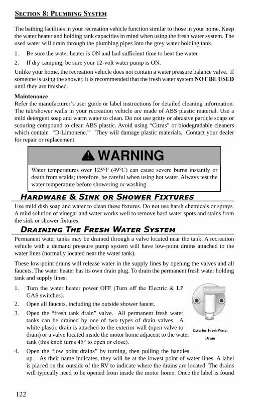
122
Section 8: Plumbing System
Exterior FreshWater
Drain
The bathing facilities in your recreation vehicle function similar to those in your home. Keep the water heater and holding tank capacities in mind when using the fresh water system. The used water will drain through the plumbing pipes into the grey water holding tank.
1. Be sure the water heater is ON and had sufficient time to heat the water.2. If dry camping, be sure your 12-volt water pump is ON.Unlike your home, the recreation vehicle does not contain a water pressure balance valve. If someone is using the shower, it is recommended that the fresh water system NOT BE USED until they are finished.
MaintenanceRefer the manufacturer’s user guide or label instructions for detailed cleaning information. The tub/shower walls in your recreation vehicle are made of ABS plastic material. Use a mild detergent soap and warm water to clean. Do not use gritty or abrasive particle soaps or scouring compound to clean ABS plastic. Avoid using “Citrus” or biodegradable cleaners which contain “D-Limonene.” They will damage plastic materials. Contact your dealer for repair or replacement.
Hardware & Sink or Shower FixturesUse mild dish soap and water to clean these fixtures. Do not use harsh chemicals or sprays. A mild solution of vinegar and water works well to remove hard water spots and stains from the sink or shower fixtures.
Draining The Fresh Water SystemPermanent water tanks may be drained through a valve located near the tank. A recreation vehicle with a demand pressure pump system will have low-point drains attached to the water lines (normally located near the water tank).
These low-point drains will release water in the supply lines by opening the valves and all faucets. The water heater has its own drain plug. To drain the permanent fresh water holding tank and supply lines:
1. Turn the water heater power OFF (Turn off the Electric & LP GAS switches).
2. Open all faucets, including the outside shower faucet.3. Open the “fresh tank drain” valve. All permanent fresh water
tanks can be drained by one of two types of drain valves. A white plastic drain is attached to the exterior wall (open valve to drain) or a valve located inside the motor home adjacent to the water tank (this knob turns 45° to open or close).
4. Open the “low point drains” by turning, then pulling the handles up. As their name indicates, they will be at the lowest point of water lines. A label is placed on the outside of the RV to indicate where the drains are located. The drains will typically need to be opened from inside the motor home. Once the label is found
Water temperatures over 125°F (49°C) can cause severe burns instantly or death from scalds; therefore, be careful when using hot water. Always test the water temperature before showering or washing.
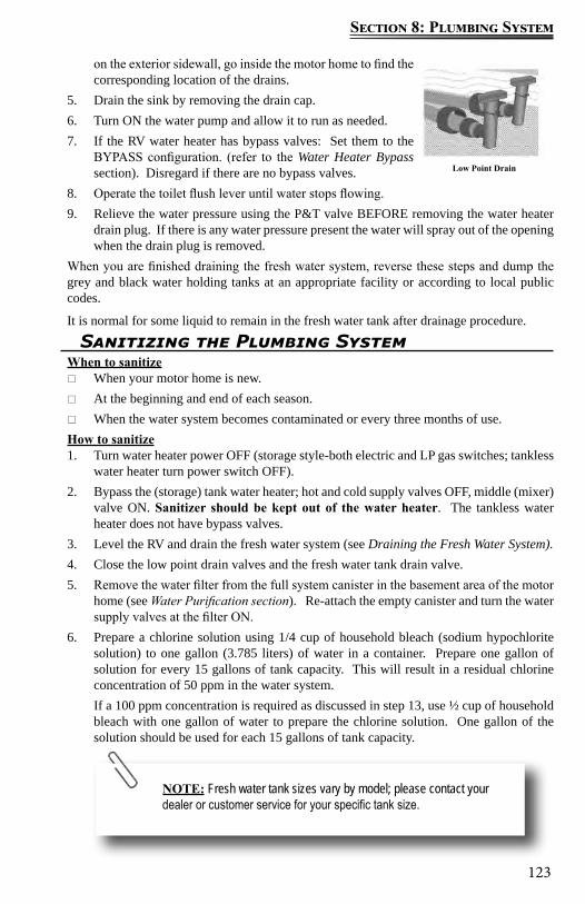
123
Section 8: Plumbing System
on the exterior sidewall, go inside the motor home to find the corresponding location of the drains.
5. Drain the sink by removing the drain cap. 6. Turn ON the water pump and allow it to run as needed. 7. If the RV water heater has bypass valves: Set them to the
BYPASS configuration. (refer to the Water Heater Bypass section). Disregard if there are no bypass valves.
8. Operate the toilet flush lever until water stops flowing. 9. Relieve the water pressure using the P&T valve BEFORE removing the water heater
drain plug. If there is any water pressure present the water will spray out of the opening when the drain plug is removed.
When you are finished draining the fresh water system, reverse these steps and dump the grey and black water holding tanks at an appropriate facility or according to local public codes.
It is normal for some liquid to remain in the fresh water tank after drainage procedure.
Low Point Drain
Sanitizing the Plumbing SystemWhen to sanitize
When your motor home is new. At the beginning and end of each season. When the water system becomes contaminated or every three months of use.
How to sanitize1. Turn water heater power OFF (storage style-both electric and LP gas switches; tankless
water heater turn power switch OFF).2. Bypass the (storage) tank water heater; hot and cold supply valves OFF, middle (mixer)
valve ON. Sanitizer should be kept out of the water heater. The tankless water heater does not have bypass valves.
3. Level the RV and drain the fresh water system (see Draining the Fresh Water System). 4. Close the low point drain valves and the fresh water tank drain valve.5. Remove the water filter from the full system canister in the basement area of the motor
home (see Water Purification section). Re-attach the empty canister and turn the water supply valves at the filter ON.
6. Prepare a chlorine solution using 1/4 cup of household bleach (sodium hypochlorite solution) to one gallon (3.785 liters) of water in a container. Prepare one gallon of solution for every 15 gallons of tank capacity. This will result in a residual chlorine concentration of 50 ppm in the water system. If a 100 ppm concentration is required as discussed in step 13, use ½ cup of household bleach with one gallon of water to prepare the chlorine solution. One gallon of the solution should be used for each 15 gallons of tank capacity.
NOTE: Fresh water tank sizes vary by model; please contact your dealer or customer service for your specific tank size.
124
Section 8: Plumbing System
7. Attach the short hose supplied with your recreation vehicle to the fresh water connection inlet (on the utility center or on the outside of the motor home). Place the other end of the hose in a container holding the sanitized solution. To assist the syphoning process set the container on a flat surface approximately (2) feet above ground level.
8. Place the utility center valves in the SANITIZE TANK position.9. Turn the water pump ON. 10. Solution will be drawn into the fresh water tank. When all the solution is in the tank, set
the utility center water valves to the city fill tank position.11. Remove the container and the short hose from the fresh water connection inlet.12. Attach a hose (can be your drinking water hose) to the fresh water connection inlet and
attach the other end of the hose to a potable pressurized water source. 13. Turn on the pressurized water source and finish filling the fresh water tank.14. When the tank is full, turn off the water source, disconnect the hose from the water
source, and remove it from the fresh water connection inlet (at the utility center or on the outside of the motor home).
15. Set the utility center valves to the NORMAL position.16. Turn the water pump ON.17. Open all hot water faucets one by one until water begins to flow continuously and a
chlorine smell is noticeable. Include outside shower faucets (if so equipped).18. Close the hot water faucets and repeat opening all cold water faucets one by one until
you smell chlorine. Include outside shower faucets (if so equipped) and toilet.19. Let the solution remain in the system for at least four hours when disinfecting with 50
PPM residual chlorine. If a shorter time period is desired, then a 100 PPM chlorine concentration should be permitted to sit in the system for at least one hour.
20. After the required period, drain the chlorine solution from the fresh water system (see Draining The Fresh Water System). Since the water heater was bypassed there should be no sanitizer in the (storage) tank water heater.
Rinse the system with fresh water: 21. Re-fill the fresh water tank using clean (potable) water. Refer to steps 12-14 to re-fill
the tank. If city water is not available, the tank can be siphon filled. (refer to Country Fill section)
22. Set the (storage) tank water heater bypass valves to normal: hot & cold supply lines ON, middle (mixer) valve OFF.
23. Set utility center water valves to the normal position and turn the pump ON to circulate fresh water through the lines.
NOTE: For complete sanitizing of the fresh water tank, the unit should be driven around for a brief time allowing the solution to splash the sides and top of the tank.
125
Section 8: Plumbing System
24. Open hot & cold lines to all faucets (including outside shower) until chlorine smell is gone.
25. Restore power to the (storage) tank water heater only when it is full of water. Tankless water heater; turn the power switch ON (water is heated on demand).
NOTE: If a chlorine taste still lingers in the water, flush the water system with a solution consisting of one-quart vinegar to five gal-lons of clean water. Re-flush as necessary. The vinegar solution may damage the water heater or the water filter, so both must be bypassed again before performing this operation. To add the vinegar solution, follow the same procedure used to add the sanitizer to the system.
Winterization
Preparing your motor home for colder weather or storage is very important for most states and Canada. Failure to prepare your motor home may cause water supply lines and the water heater to freeze.
No commodity or product should be added to the fresh water system to ensure freeze protection other than RV antifreeze.
The motor home should be winterized at the end of the camping season or when the motor home will be exposed to temperatures that will fall at or below 32°F (0°C). Repairs due to freezing are not covered by warranty.
The preferred method is to winterize the plumbing system with RV antifreeze. Please read, understand and follow all instructions before beginning to winterize you motor home.
Winterizing with Antifreeze methodIt may be easier to winterize the motor home with another person to assist you.
1. Level the motor home and drain the fresh water plumbing system.2. Turn the water valves OFF on each side of the water filter canister. The canister is
Never apply air pressure to the water system with any of the valves in the closed position. Air pressure applied to a closed valve, faucet or low point drain could potentially damage the seals and cause water leaks. If you have questions, consult with your RV dealer.
Automotive antifreeze (ethylene glycol) and windshield washer antifreeze (methanol) are poisonous. Never use these products in your fresh water system. These products are harmful and may be fatal if swallowed
126
Section 8: Plumbing System
located behind the utility center. Unscrew the canister and remove the filter. Re-attach the empty canister and turn the water valves ON (refer to the Water Purification section).
3. Water heater power switches (12V GAS & 120V ELECTRIC at the command center) should be turned OFF. Gas valve at the water heater should be turned OFF. The tankless water power switch is located outside the RV.
4. Turn the water heater bypass valves (if so equipped) to the BYPASS position. Tankless water heater will not have bypass valves.
5. Move the valves to the “Sanitize/Winterize Lines” position. The low point drains must be closed for the antifreeze to siphon through the lines.
6. Attach the short hose supplied with the motor home to the fresh water connection inlet and insert the other end of the hose into a gallon container of RV antifreeze (this quantity should be enough to winterize the motor home). To assist the siphoning process, put the container on a surface approximately two feet above ground level.
7. Turn the water pump ON. If the water pump fails to self-prime, temporarily open the low point drains. Close the low point drains as soon as the water pump primes (RV antifreeze will begin draining out)] and before continuing to the next step.
8. Open the hot water line on all the faucets (kitchen, lavatory, shower and outside shower) until RV antifreeze begins to flow continuously (refer to “Winterizing Dishwasher and Winterizing Washing Machine instructions in this section if applicable).
9. Close the faucet hot water lines and repeat with the cold water lines on all the faucets. Flush the toilet a couple of times until you see antifreeze in the bowl.
When you are done adding RV antifreeze10. Remove the short hose from the container of RV antifreeze.11. To prevent staining, wipe the RV antifreeze out of the sinks, shower (or tub) and toilet
using a soft, dry cloth. If needed, contact your RV dealer for assistance.Winterizing the Dishwasher (if so equipped)While you are putting antifreeze in the water lines follow these instructions to winterize the dishwasher:
1. Use the dishwasher remote control to unlock the dishwasher. Open the dishwasher and select RINSE.
2. Close the dishwasher and the rinse cycle should begin. This will bring antifreeze into the dishwasher through the water lines.
3. Pause the dishwasher with the remote (wait for 3 beeps), open the dishwasher and add several cups of antifreeze into the tub.
4. Close the dishwasher, re-start it with the remote, then press and hold the button on the remote until you hear a quick double beep. The dishwasher will drain the antifreeze into the pump assembly.
Winterizing Washing Machine (if so equipped)While you are putting antifreeze in the water lines follow these instructions to winterize the washing machine:
1. Set the Cycle Selector to RINSE.
127
Section 8: Plumbing System
2. Set the Wash Temperature to WARM.3. Press the ON/OFF button to turn the washer on.4. Press the START button to begin the rinse cycle.5. Antifreeze should flow into the drum. When antifreeze begins flowing in the drum,
press and hold the START button to cancel the rinse cycle. Add several cups of antifreeze in the drum.
6. Turn the Cycle Selector to DRAIN.7. Press the START button to begin draining the antifreeze out of the drum and into the
pump assembly.8. When antifreeze disappears out of the drum press and hold the START button to cancel
the Drain cycle. Press the ON/OFF button to turn off the washer.To De-winterize the Dishwasher and Washing MachineRun a regular empty wash cycle which will remove antifreeze from the dishwasher, washing machine and water lines. You can now use the dishwasher and washing machine normally.
Black/Grey Water SystemWater from the sinks and shower (or tub) flow into the gray water (or waste water) holding tank. Water from the toilet will flow into the sewage (or black water) holding tank. Certain floor plans may also have the lavatory draining into the waste (black) tank.
Drain pipesThe drain pipes have a “P-trap” installed to help prevent odors from escaping into the motor home. During travel, water from the P-traps may spill and permit odors into the motor home. These odors come from food particles decomposing in the tank.
By adding water and using a RV approved deodorizing agent you will dissolve the contents faster and will keep the drain lines and tanks clean and free flowing. These chemicals are available at an RV supply store or your dealer.
VentsAnother important part of this system is the vent pipes and vents that release air from the grey and black water holding tanks. The exterior vent cap is attached to the roof and must be kept clear of obstructions to perform as intended.
On some models, the vent pipe may be part of the drainage system referred to as a “wet vent” (water flows downward as air flows upward in the same pipe).
Black/Grey Water Holding TanksDump the gray and black water holding tanks before traveling to avoid carrying unnecessary weight. The weight of the holding tank contents is not calculated into the motor home cargo carrying capacity (this extra weight would reduce your available cargo capacity).
Traveling with the tanks full can affect your fuel consumption, and depending on the location of the tanks, can affect your vehicle handling characteristics.
If you are dry camping and cannot immediately empty your holding tanks, reduce your vehicle speed until you reach a dumping station.
When connected to the sewer drain line at a campground, keep the “black tank drain” valve closed until the holding tank is at least ¾ full. This will provide sufficient water to assist in complete draining of the black water holding tank. Repeat as needed.
128
Section 8: Plumbing System
Before using the motor home, or after dumping the grey and black water holding tanks, always add the proper amount of deodorant to the black water tank to prevent odors and help break down holding tank contents (unless winterizing). Follow the deodorant bottle or package instructions. Driving to a disposal site will normally loosen any accumulated waste debris or solids from the sides of the holding tanks.
Never leave the black tank drain in the open position continuously when connected to the campground sewer system. Leaving the drain open will allow the liquid to drain out increasing the potential for a blockage in the tank. Keeping the drain in the closed position will prevent debris from accumulating in the tank.
Do not add automotive antifreeze or caustic chemicals, such as laundry detergents, into the holding tanks. Although these products may have a deodorizing effect, they may damage the plastic and rubber parts of the plumbing system or the components.
Black & Grey Tank DrainsThe grey tank drain and black tank drain are also referred to as dump valves. Always drain the black water holding tank first so the following grey tank waste water can help rinse any solids or debris from the dump outlet and sewer hose.
1. To make drainage easier, level the motor home.2. Remove the sewer hose housing dust cap, and attach the sewer hose.3. Place the end of the sewer hose into the approved dump station.4. Open the black tank dump valve (close it when the black water holding tank is emptied).5. Open the grey tank dump valve (close it when the grey holding tank is emptied).6. Remove, clean and store the sewer hose.7. Close the sewer hose housing dust cap.You can locate many dump stations throughout the United States and Canada in Woodall’s, Rand McNally Camp Guide, Good Sam Camp Guide, KOA Kampgrounds Camp Guide and various other publications. Some fuel stations also have dump stations.
Please contact your RV dealer for assistance in the purchase and installation of a sewer hose and/or sewer hose extension (if needed).Macerator Pump System (if so equipped)
Your motor home may be equipped with a macerator pump system used to discharge waste from the gray and black waste tank. The system has a 1-1/2 inch diameter flexible hose that runs from the pump (behind the utility center panel) and attaches to a separate compartment on the exterior of the motor home (beside the utility center). Not all models are equipped with external storage compartment. The system when powered on can discharge waste (uphill if necessary) up to a distance of 150 feet.
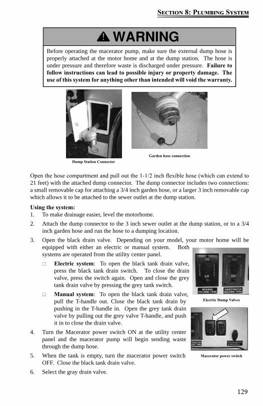
129
Section 8: Plumbing System
Before operating the macerator pump, make sure the external dump hose is properly attached at the motor home and at the dump station. The hose is under pressure and therefore waste is discharged under pressure. Failure to follow instructions can lead to possible injury or property damage. The use of this system for anything other than intended will void the warranty.
Open the hose compartment and pull out the 1-1/2 inch flexible hose (which can extend to 21 feet) with the attached dump connector. The dump connector includes two connections: a small removable cap for attaching a 3/4 inch garden hose, or a larger 3 inch removable cap which allows it to be attached to the sewer outlet at the dump station.
Using the system: 1. To make drainage easier, level the motorhome.2. Attach the dump connector to the 3 inch sewer outlet at the dump station, or to a 3/4
inch garden hose and run the hose to a dumping location.3. Open the black drain valve. Depending on your model, your motor home will be
equipped with either an electric or manual system. Both systems are operated from the utility center panel.
Electric system: To open the black tank drain valve, press the black tank drain switch. To close the drain valve, press the switch again. Open and close the grey tank drain valve by pressing the grey tank switch.
Manual system: To open the black tank drain valve, pull the T-handle out. Close the black tank drain by pushing in the T-handle in. Open the grey tank drain valve by pulling out the grey valve T-handle, and push it in to close the drain valve.
4. Turn the Macerator power switch ON at the utility center panel and the macerator pump will begin sending waste through the dump hose.
5. When the tank is empty, turn the macerator power switch OFF. Close the black tank drain valve.
6. Select the gray drain valve.
Garden hose connectionDump Station Connector
Macerator power switch
Electric Dump Valves
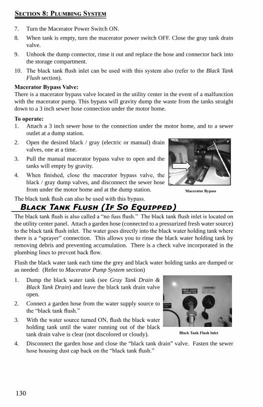
130
Section 8: Plumbing System
7. Turn the Macerator Power Switch ON.8. When tank is empty, turn the macerator power switch OFF. Close the gray tank drain
valve.9. Unhook the dump connector, rinse it out and replace the hose and connector back into
the storage compartment.10. The black tank flush inlet can be used with this system also (refer to the Black Tank
Flush section).Macerator Bypass Valve:There is a macerator bypass valve located in the utility center in the event of a malfunction with the macerator pump. This bypass will gravity dump the waste from the tanks straight down to a 3 inch sewer hose connection under the motor home.
To operate:1. Attach a 3 inch sewer hose to the connection under the motor home, and to a sewer
outlet at a dump station. 2. Open the desired black / gray (electric or manual) drain
valves, one at a time. 3. Pull the manual macerator bypass valve to open and the
tanks will empty by gravity. 4. When finished, close the macerator bypass valve, the
black / gray dump valves, and disconnect the sewer hose from under the motor home and at the dump station.
The black tank flush can also be used with this bypass.Macerator Bypass
Black Tank Flush (If So Equipped)The black tank flush is also called a “no fuss flush.” The black tank flush inlet is located on the utility center panel. Attach a garden hose (connected to a pressurized fresh water source) to the black tank flush inlet. The water goes directly into the black water holding tank where there is a “sprayer” connection. This allows you to rinse the black water holding tank by removing debris and preventing accumulation. There is a check valve incorporated in the plumbing lines to prevent back flow.
Flush the black water tank each time the grey and black water holding tanks are dumped or as needed: (Refer to Macerator Pump System section)
1. Dump the black water tank (see Gray Tank Drain & Black Tank Drain) and leave the black tank drain valve open.
2. Connect a garden hose from the water supply source to the “black tank flush.”
3. With the water source turned ON, flush the black water holding tank until the water running out of the black tank drain valve is clear (not discolored or cloudy).
4. Disconnect the garden hose and close the “black tank drain” valve. Fasten the sewer hose housing dust cap back on the “black tank flush.”
Black Tank Flush Inlet

131
Section 8: Plumbing System
The black tank drain valve must be OPEN any time there is a hose (water supply) connected to the black tank flush.
Do not leave any hose (water supply) connected to the black tank flush when it is not in use.
Do not use the same hose to fill your fresh (potable) water tank that is used for the black tank flush.
ToiletThe toilet is efficient and easy to operate. Generally, more water is required only when flushing solids. Prior to using the sanitation system, it is strongly recommended to flush the toilet several times to release sufficient water into the holding tank. If there is not a sufficient amount of water used during flushing, the waste materials may not evacuate properly from the drain line to the tank. Clogged tanks and pipes could eventually occur.
The toilet system will perform better when water is run for ten to fifteen seconds after flushing to ensure that the waste will proceed to the bottom of the tank.
Unlike a toilet in a home, which may use up to seven gallons of water per flush, the average recreation vehicle system uses one to three quarts (1 - 3 liters). For added convenience and better sanitation system performance, it is advisable to always have four to six inches (10 - 15 cm) of water in the toilet.
It is important to add enough water to prevent solid waste buildup. The following guidelines will help to prevent solid waste buildup. Sewage (black) tank preparation
To prevent help toilet blockage, always use RV grade single-ply toilet paper. Do not flush paper towels, diapers, sanitary napkins or other foreign objects down the toilet.
It is important to prevent solid waste buildup. Follow the toilet manufacturer’s recommended instructions each time after emptying the black water holding tank.
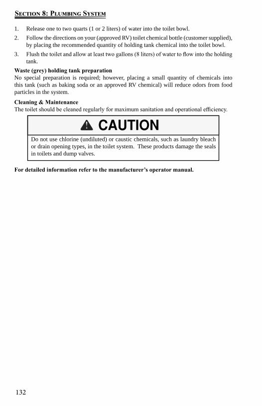
132
Section 8: Plumbing System
Do not use chlorine (undiluted) or caustic chemicals, such as laundry bleach or drain opening types, in the toilet system. These products damage the seals in toilets and dump valves.
1. Release one to two quarts (1 or 2 liters) of water into the toilet bowl.2. Follow the directions on your (approved RV) toilet chemical bottle (customer supplied),
by placing the recommended quantity of holding tank chemical into the toilet bowl.3. Flush the toilet and allow at least two gallons (8 liters) of water to flow into the holding
tank.Waste (grey) holding tank preparationNo special preparation is required; however, placing a small quantity of chemicals into this tank (such as baking soda or an approved RV chemical) will reduce odors from food particles in the system.
Cleaning & MaintenanceThe toilet should be cleaned regularly for maximum sanitation and operational efficiency.
For detailed information refer to the manufacturer’s operator manual.
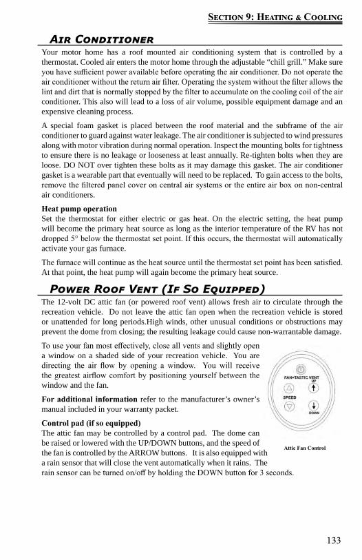
133
Section 9: Heating & Cooling
Air Conditioner Your motor home has a roof mounted air conditioning system that is controlled by a thermostat. Cooled air enters the motor home through the adjustable “chill grill.” Make sure you have sufficient power available before operating the air conditioner. Do not operate the air conditioner without the return air filter. Operating the system without the filter allows the lint and dirt that is normally stopped by the filter to accumulate on the cooling coil of the air conditioner. This also will lead to a loss of air volume, possible equipment damage and an expensive cleaning process.
A special foam gasket is placed between the roof material and the subframe of the air conditioner to guard against water leakage. The air conditioner is subjected to wind pressures along with motor vibration during normal operation. Inspect the mounting bolts for tightness to ensure there is no leakage or looseness at least annually. Re-tighten bolts when they are loose. DO NOT over tighten these bolts as it may damage this gasket. The air conditioner gasket is a wearable part that eventually will need to be replaced. To gain access to the bolts, remove the filtered panel cover on central air systems or the entire air box on non-central air conditioners.
Heat pump operationSet the thermostat for either electric or gas heat. On the electric setting, the heat pump will become the primary heat source as long as the interior temperature of the RV has not dropped 5° below the thermostat set point. If this occurs, the thermostat will automatically activate your gas furnace.
The furnace will continue as the heat source until the thermostat set point has been satisfied. At that point, the heat pump will again become the primary heat source.
Power Roof Vent (If So Equipped)The 12-volt DC attic fan (or powered roof vent) allows fresh air to circulate through the recreation vehicle. Do not leave the attic fan open when the recreation vehicle is stored or unattended for long periods.High winds, other unusual conditions or obstructions may prevent the dome from closing; the resulting leakage could cause non-warrantable damage.
To use your fan most effectively, close all vents and slightly open a window on a shaded side of your recreation vehicle. You are directing the air flow by opening a window. You will receive the greatest airflow comfort by positioning yourself between the window and the fan.
For additional information refer to the manufacturer’s owner’s manual included in your warranty packet.
Control pad (if so equipped)The attic fan may be controlled by a control pad. The dome can be raised or lowered with the UP/DOWN buttons, and the speed of the fan is controlled by the ARROW buttons. It is also equipped with a rain sensor that will close the vent automatically when it rains. The rain sensor can be turned on/off by holding the DOWN button for 3 seconds.
Attic Fan Control
134
Section 9: Heating & Cooling
The furnace should be inspected periodically (monthly during the heating season) for presence of soot on the vent. Soot is formed whenever combustion is incomplete. This is a visual warning that the furnace is operating in an unsafe manner. If soot is observed on the vent, immediately shut the furnace OFF and contact a qualified service agency. Operating the furnace under this condition could lead to serious property damage, personal injury or loss of life.
To ensure your personal safety, do not obstruct or alter the furnace in any manner. Do not install screens over the vent for any reason. Screens will become restricted and cause unsafe furnace operation. For your safety, only the manufacturer’s factory authorized parts should be used on your furnace.
Furnace The furnace installed in your recreation vehicle is controlled by a 12-volt DC thermostat. Depending on your model, there may be up to two thermostats in your recreation vehicle to enabling you to control the temperature to your comfort level.
The furnace requires both 12-volt power and propane gas for full operation. Make sure you have sufficient power available before operating your furnace.
If you have any questions contact your dealer or Customer Service. A qualified RV technician should perform all furnace maintenance at least once a year (more often depending on furnace usage). Never attempt to repair the furnace yourself,
To ensure your personal safety, do not obstruct or alter the furnace in any manner. Do not install screens over the vent for any reason. Screens will become restricted and cause unsafe furnace operation. For your safety, only the manufacturer’s factory authorized parts should be used on your furnace.
The furnace should be inspected periodically (monthly during the heating season) for presence of soot on the vent. Soot is formed whenever combustion is incomplete. This is a visual warning that the furnace is operating in an unsafe manner. If soot is observed on the vent, immediately shut the furnace OFF and contact a qualified service agency. Operating the furnace under this condition could lead to serious property damage, personal injury or loss of life.
135
Section 10: Appliances
Convection Microwave
For details on operation, cleaning and safety information, refer to the manufacturer’s user guide included in the Owner’s Portfolio, or visit the manufacturer’s website.
The convection microwave bridges the gap between microwaving your food and conventional cooking. Make sure there is sufficient 120-volt power available before operating the convection microwave (refer to Sec. 6 Electrical Systems, Calculating electrical load).
Microwave Oven UseFor list of preset programs, see the Quick Reference Guide provided with your model.
General CleaningIMPORTANT: Before cleaning, make sure all controls are off and the microwave oven is cool. Always follow label instructions on cleaning products.
To avoid damage to the microwave oven caused by arcing due to soil buildup keep cavity, microwave inlet cover, cooking rack supports, and area where the door touches the frame clean.
Clean with mild soap, water and a soft cloth or sponge, or as indicated below.
Grease filters: mild soap and water or dishwasher. Door and exterior: mild soap and water, or glass cleaner applied to paper towel. Control panel: sponge or soft cloth and water. Stainless steel (on some models): mild soap and water, then rinse with clean water and
dry with soft cloth, or use stainless steel cleaner. Turntable: mild soap and water or dishwasher. Rack(s): mild soap, water and washcloth. Dishwasher cleaning is not recommended.
Never use the microwave cavity for storage. The microwave cavity should always be empty when not in use.
NOTE: To prevent damage, remove the turntable from the micro-wave when traveling.
NOTE: Make sure you are connected to a 120-volt power source.
Induction Cooktop (If So Equipped)Induction cooktops are more efficient than gas or electric cooktops. The cooking surface heats through magnetic induction. Cookware for induction cooking should be magnetic (steel or cast iron) and have a flat bottom. Cookware made from aluminum, corning ware,
136
Section 10: Appliances
Kitchen Range & Oven (If So Equipped)
If using glass, glass/ceramic, ceramic, earthenware or other glazed utensils (or cookware) verify it is safe for use on the top burners. Only certain types of utensils (or cookware) are suitable for surface or top burner use.
During and after use, do not touch or let clothing or other flammable material come in contact with the top burners (or heating elements), burner grates or other areas near the top burners or oven until they have had sufficient time to cool. These areas can get hot enough to cause burns.
Pyrex, or glass will not work by just placing them on the surface, but can be used if they are placed on top of a magnetic interface disk which will function as a conventional hot plate. Stainless steel cookware may or may not work. If there is a doubt as to whether a certain pan or skillet will work, check it with a magnet. If the magnet clings to it, it will probably work with the induction cooktop; if it doesn’t or clings weakly it probably won’t work.
Induction cooktops are much safer to use than electric or gas.
The stovetop stays cool, no burned fingers or hands if you touch the surface. Only the cooking vessel gets hot. The cooking surface only works when there is a magnetic pan (or interface disk) in
place on it. Sensors detect the amount of ferrous material in the area of the magnetic field and if it is not the size of a small pan it won’t turn on.
Induction cooktops will not heat up the kitchen. Very rapid temperature increases can be achieved and very fine adjustments can be
made.Refer to manufacturer’s manual for detailed operating and cleaning instructions.
Aluminum foil should NEVER be used with an induction cooktop. It can permanently melt to the cooktop cracking the surface or causing permanent damage.
Touching a hot pan or cooking vessel can still cause burns. Use pot holders or oven mitts to remove hot pans from the cooktop..
137
Section 10: Appliances
Never leave cooking food unattended. Turn pan handles inward, but not over the tops of the other range burners. Ensure that pans used are large enough to contain the food and avoid boil-overs. Heavy splattering or spills left on the cooktop can ignite and cause burns.
To prevent damage, always use the manufacturer’s recommended size flat bottom pan(s). Generally, the pan should be large enough to cover the burner, but not be more than one inch larger than the burner grate.
Do not use a broiler pan, griddle or any other large utensil that covers more than one burner at a time. This will create excessive heat that may cause melting, sooting or discoloration.
The use of undersized pans could expose a portion of the heating element to direct contact and may result in ignition of clothing. Proper relationship of pans to burner will improve efficiency.
Refer to the manufacturer’s user guide for detailed operation, cleaning and safety information.Oven (if so equipped)The propane gas oven must have 12-volt power to operate. If you have any questions contact your dealer or our customer service department. Do not use the oven as a storage area.
Refer to the manufacturer’s user guide for detailed operation, cleaning and safety information.
Do not cover the oven vent openings while the oven is in operation. Restricting the flow of combustion air will create an asphyxiation hazard.
NOTE: To help reduce potential condensation or unwanted cooking odors, turn on the overhead kitchen roof vent or the range hood vent (if so equipped).
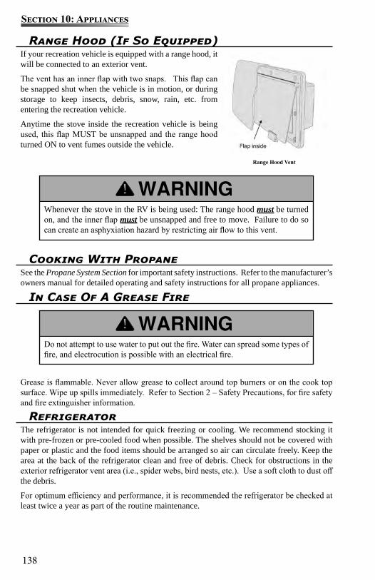
138
Section 10: Appliances
Range Hood Vent
Range Hood (If So Equipped)If your recreation vehicle is equipped with a range hood, it will be connected to an exterior vent.
The vent has an inner flap with two snaps. This flap can be snapped shut when the vehicle is in motion, or during storage to keep insects, debris, snow, rain, etc. from entering the recreation vehicle.
Anytime the stove inside the recreation vehicle is being used, this flap MUST be unsnapped and the range hood turned ON to vent fumes outside the vehicle.
Whenever the stove in the RV is being used: The range hood must be turned on, and the inner flap must be unsnapped and free to move. Failure to do so can create an asphyxiation hazard by restricting air flow to this vent.
Cooking With PropaneSee the Propane System Section for important safety instructions. Refer to the manufacturer’s owners manual for detailed operating and safety instructions for all propane appliances.
In Case Of A Grease Fire
Grease is flammable. Never allow grease to collect around top burners or on the cook top surface. Wipe up spills immediately. Refer to Section 2 – Safety Precautions, for fire safety and fire extinguisher information.
Do not attempt to use water to put out the fire. Water can spread some types of fire, and electrocution is possible with an electrical fire.
RefrigeratorThe refrigerator is not intended for quick freezing or cooling. We recommend stocking it with pre-frozen or pre-cooled food when possible. The shelves should not be covered with paper or plastic and the food items should be arranged so air can circulate freely. Keep the area at the back of the refrigerator clean and free of debris. Check for obstructions in the exterior refrigerator vent area (i.e., spider webs, bird nests, etc.). Use a soft cloth to dust off the debris.
For optimum efficiency and performance, it is recommended the refrigerator be checked at least twice a year as part of the routine maintenance.

139
Section 10: Appliances
If you smell propane gas STOP! Follow the directions located in your manufacturer’s owner’s manual and in this manual.
NOTE: If you are using electric to power the refrigerator, make sure you are connected to a 120-volt power source.
The ice maker (if so equipped) should be turned off and the ice tray emptied when power to your recreation vehicle has been shut off. With no power, the ice will melt and water may “pool” in the refrigerator door. When power is restored, the vibration may cause this water to run out of the door and on to the vehicle floor.
Gas/electric models (If So Equipped)
Residential models (If So Equipped)
For detailed operating and safety information, refer to the manufacturer’s user guide included in the Warranty Packet.
Cleaning Your RefrigeratorThe following are general cleaning guidelines. For detailed information on cleaning your specific refrigerator, refer to the manufacturer’s user’s guide.
Cleaning the interior1. Unplug refrigerator or disconnect power.2. Hand wash, rinse, and dry removable parts and interior surfaces thoroughly. Use a clean
sponge or soft cloth and a mild detergent in warm water.3. For the inside of the refrigerator, use a warm water and baking soda solution
consisting of approximately 1 tablespoon (15ml) baking soda to 1 quart (1 liter) of water. This solution both cleans and neutralizes odors. Rinse and wipe dry.
4. Leave an open box of baking soda in the refrigerator and freezer compartments to help prevent odors.
NOTE: Do not use abrasive or harsh cleaners such as window sprays, scouring cleansers, flammable fluids, cleaning waxes, concentrated detergents, bleaches or cleansers containing petroleum products on plastic parts, interior and door liners or gaskets. Do not use paper towels, scouring pads, or other harsh cleaning tools.
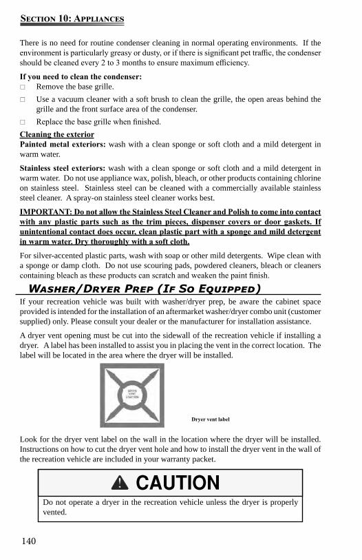
140
Section 10: Appliances
There is no need for routine condenser cleaning in normal operating environments. If the environment is particularly greasy or dusty, or if there is significant pet traffic, the condenser should be cleaned every 2 to 3 months to ensure maximum efficiency.
If you need to clean the condenser: Remove the base grille. Use a vacuum cleaner with a soft brush to clean the grille, the open areas behind the
grille and the front surface area of the condenser. Replace the base grille when finished.
Cleaning the exteriorPainted metal exteriors: wash with a clean sponge or soft cloth and a mild detergent in warm water.
Stainless steel exteriors: wash with a clean sponge or soft cloth and a mild detergent in warm water. Do not use appliance wax, polish, bleach, or other products containing chlorine on stainless steel. Stainless steel can be cleaned with a commercially available stainless steel cleaner. A spray-on stainless steel cleaner works best.
IMPORTANT: Do not allow the Stainless Steel Cleaner and Polish to come into contact with any plastic parts such as the trim pieces, dispenser covers or door gaskets. If unintentional contact does occur, clean plastic part with a sponge and mild detergent in warm water. Dry thoroughly with a soft cloth.
For silver-accented plastic parts, wash with soap or other mild detergents. Wipe clean with a sponge or damp cloth. Do not use scouring pads, powdered cleaners, bleach or cleaners containing bleach as these products can scratch and weaken the paint finish.
Washer/Dryer Prep (If So Equipped)If your recreation vehicle was built with washer/dryer prep, be aware the cabinet space provided is intended for the installation of an aftermarket washer/dryer combo unit (customer supplied) only. Please consult your dealer or the manufacturer for installation assistance.
A dryer vent opening must be cut into the sidewall of the recreation vehicle if installing a dryer. A label has been installed to assist you in placing the vent in the correct location. The label will be located in the area where the dryer will be installed.
Look for the dryer vent label on the wall in the location where the dryer will be installed. Instructions on how to cut the dryer vent hole and how to install the dryer vent in the wall of the recreation vehicle are included in your warranty packet.
Do not operate a dryer in the recreation vehicle unless the dryer is properly vented.
Dryer vent label
141
Section 10: Appliances
Water Heater – See plumbing section
Gas dryers should NEVER be installed in your recreation vehicle. Dryer prep has been designed for electric dryer operation ONLY.

142
Section 10: Appliances
Notes:
143
Section 11: Electronics
Satellite Dish (if so equipped)Your motor home may be equipped with the TRAV’LER® automatic multi-satellite TV antenna.
The following is an overview of the antenna operation. For detailed operating instructions, including receiver set up, refer to the manufacturer’s user guide included in your Owner’s Portfolio.
The TRAV’LER antenna offers a simple one-button operation. Simply press “POWER,” and the antenna will automatically begin searching for satellites. The instructions assume that the antenna is already in the stowed position.
1. Press and hold “POWER” for two seconds or until the TRAV’LER interface displays “POWER ON.”
2. Once the unit has been powered on, release “POWER.3. The interface screen will display the type of satellite dish on the top line.4. The TRAV’LER antenna will enter the search mode as part of its normal operation and
will display “Searching” on the bottom line.5. The antenna will find its home position and begin to look for a satellite. Upon finding a
satellite, the antenna will fine-tune or “peak” on the signal.6. In automatic search mode, the TRAV’LER antenna will lock onto three different
satellites: 99°, 101°, and 103°. The antenna will display an asterisk for each satellite found.
If the receiver is already set up in the RV, you are now ready to watch TV
Before traveling, make sure to press “POWER” and wait for the antenna to start to power up; then press “POWER” again to initiate the stow sequence. See below for information on stowing before traveling.
User Menu for Manual OperationThe interface includes a user menu for some advanced features. The options most commonly used are the ability to change the dish type, check software/hardware versions, change desired satellite configuration, or manually move the dish.
The TRAV’LER antenna is not meant for use while traveling. To stow the unit when you are ready to travel, press “POWER” one time. The unit will stop what it is doing and return to the stowed position. The TRAV’LER interface will not turn off unless the TRAV’LER antenna is successfully stowed. Visually inspect that the antenna is in the stowed/travel
NOTE: If you want to turn off the power to the TRAV’LER antenna after the antenna has locked onto satellites, press “POWER” and “SELECT” at the same time.
Improper use of the user menu could cause damage to the TRAV’LER antenna and/or vehicle. Do not enter the user menu for regular operation.
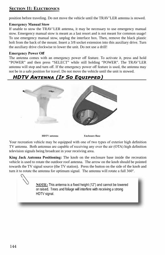
144
Section 11: Electronics
HDTV Antenna (If So Equipped)
Your recreation vehicle may be equipped with one of two types of exterior high definition TV antenna. Both antennas are capable of receiving any over the air (OTA) high definition television signals being broadcast in your receiving area.
King Jack Antenna Positioning: The knob on the enclosure base inside the recreation vehicle is used to rotate the outdoor roof antenna. The arrow on the knob should be pointed towards the TV signal source (the TV station). Press the button on the side of the knob and turn it to rotate the antenna for optimum signal. The antenna will rotate a full 360°.
Enclosure BaseHDTV antenna
NOTE: This antenna is a fixed height (12”) and cannot be lowered or raised. Trees and foliage will interfere with receiving a strong HDTV signal.
position before traveling. Do not move the vehicle until the TRAV’LER antenna is stowed.
Emergency Manual StowIf unable to stow the TRAV’LER antenna, it may be necessary to use emergency manual stow. Emergency manual stow is meant as a last resort and is not meant for common usage! To use emergency manual stow, unplug the interface box. Then, remove the black plastic bolt from the back of the mount. Insert a 3/8 socket extension into this auxiliary drive. Turn the auxiliary drive clockwise to lower the unit. Do not use a drill!
Emergency Power OffThe antenna comes with an emergency power off feature. To activate it, press and hold “POWER” and then press “SELECT” while still holding “POWER”. The TRAV’LER antenna will stop and turn off. If the emergency power off feature is used, the antenna may not be in a safe position for travel. Do not move the vehicle until the unit is stowed.
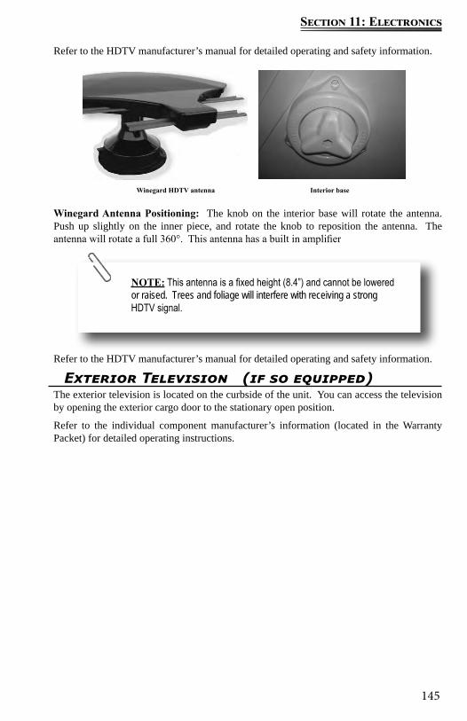
145
Section 11: Electronics
Exterior Television (if so equipped)The exterior television is located on the curbside of the unit. You can access the television by opening the exterior cargo door to the stationary open position.
Refer to the individual component manufacturer’s information (located in the Warranty Packet) for detailed operating instructions.
Refer to the HDTV manufacturer’s manual for detailed operating and safety information.
Winegard Antenna Positioning: The knob on the interior base will rotate the antenna. Push up slightly on the inner piece, and rotate the knob to reposition the antenna. The antenna will rotate a full 360°. This antenna has a built in amplifier
Refer to the HDTV manufacturer’s manual for detailed operating and safety information.
Winegard HDTV antenna Interior base
NOTE: This antenna is a fixed height (8.4”) and cannot be lowered or raised. Trees and foliage will interfere with receiving a strong HDTV signal.

146
Section 11: Electronics
Notes:
147
Secion 12: Interior
Décor ItemsDécor items such as décor glass, furniture, window treatments, shades and blinds should be cared for as follows:
Décor Glass (if so equipped)Use a glass cleaner to remove smudges, smears and spots. If there is any decorative etching on the décor glass, use care when cleaning around that area.
Furniture UpholsteryTo retain the value of your recreation vehicle, maintain the furniture upholstery carefully and keep the interior clean. Vacuum the furniture regularly using a soft brush attachment to remove any loose dirt or debris.
Fabric (if so equipped)It is recommended the fabric be professionally cleaned if it becomes stained or soiled. The professional cleaner should be made aware the fabrics that may have been treated to be fire resistant. For more information, refer to the specific furniture manufacturer’s care instructions.
Ultraleather™ (if so equipped)It is recommended the Ultraleather™ be professionally cleaned if it becomes stained or soiled. For more information, refer to the specific furniture manufacturer’s care instructions.
Leather (if so equipped)Periodic vacuuming, using a dry cloth to wipe up spills immediately, and using a damp cloth on problem areas, will help to keep your leather furniture in good condition. Leather surfaces can vary as do the cleaning methods. Refer to the furniture manufacturer’s recommendation, or consult a cleaning professional.
It is recommended you do not use any cleaners containing oils, waxes or silicones. Cleaners containing silicone can eventually destroy the finish on the leather. Cleaners containing oils or waxes should not be used as they leave residues on the surface of the leather which can attract more dirt which can eventually lead to cracking
Window treatments Fabric – Drapes and valancesDust occasionally with a vacuum and soft brush attachment. It is recommended the fabric be professionally cleaned if it becomes stained or soiled. The professional cleaner should be made aware the fabrics that may have been treated to be fire resistant.
Window ShadesShades should be vacuumed periodically to remove dust. It doesn’t matter what type of shade or fabric you have, using your vacuum cleaners upholstery brush on low suction will remove most dust and dirt from the shade.
Refer to the shade manufacturer’s owner’s manual for additional and detailed information.
Cleaning The InteriorTo keep the value of your recreation vehicle, perform regular maintenance using the proper materials and procedures. Using the wrong cleaner may result in damage to the surfaces in your vehicle. Check with the manufacturer’s information for the recommended cleaning agent. If in doubt, check to see if the cleaner will cause damage by testing a small area out of sight or contact your dealer for assistance. Do not use flammable liquids or sprays to clean the recreation vehicle.
148
Secion 12: Interior
To remove stuck on dust or stains refer to the following guide.
Solar shields: Use a sponge or soft brush and water to remove stains. A mild cleaning solution can be used to remove tougher stains. Rinse after cleaning by wetting a clean cloth in fresh water, wringing our any excess and wiping the areas where the cleaner was used.
Day/night Shades: Clean with a mild cleaning solution using a sponge or paper towel. Wipe down with water after cleaning and dry thoroughly before raising the shade. Do not use spot remover, household cleaners or detergents to remove soiled spots, as these may cause damage to fabric or loss of color from fading.
Mini Blinds: A simple dry rag may do the trick. If they’re especially dirty, you can use cold or warm water to clean them. But never use hot water.
Fill a spray bottle with water and a tiny amount of soap. Then spray a lint-free towel with the mixture and use the towel to wipe down each slat. While cleaning, try not to bend the slats. They can also be soaked in a bathtub to loosen up any debris so the slats can be wiped down easily.
Roller Shades: Can be easily cared for by simply using soapy water or a mild cleaning solution on spots. However try a small area first. Harsh household cleaners or detergents may cause damage to fabric or loss of color. It is our recommendation to dust the rails and fabrics of the shades on a regular basis. Shades should be kept in the closed or up position when not in use, to maintain pleat retention and minimize dirt and soil build-up. Do not store shades in the down position. This may cause some loss of pleat retention if the shades are not operated on a consistent basis.
NOTE: If your recreation vehicle must be stored for an extended period of time, store shades in the up position and cover your win-dows with additional protection (I.E. Cut out cardboard).
Sofa
Your motor home may be equipped with one of the following sofa styles.
Hide-a-bed Sofa or Sofa Sleeper The hide-a-bed sofa functions much the same as a regular residential hide-a-bed sofa. To make the hide-a-bed sofa into a bed, remove the seat cushions and pull the sofa back towards you firmly and gently. Activate (or deflate) the air mattress (if so equipped) using the supplied furniture manufacturer’s instructions. To convert the hide-a-bed back into the upright sofa position, reverse the process.
Jack Knife Sofa The Jack Knife sofa functions much the same as a residential futon. To make the sofa in to a bed, lift up on the bottom seat cushion and pull it towards you. The sofa back will drop down to provide a sleeping surface. For additional comfort and to reduce fabric damage,
Always use seatbelts if sitting in the sofa while the motor home is in transit.
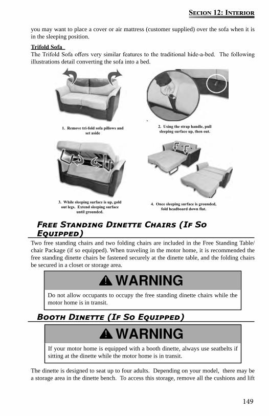
149
Secion 12: Interior
you may want to place a cover or air mattress (customer supplied) over the sofa when it is in the sleeping position.
Trifold Sofa The Trifold Sofa offers very similar features to the traditional hide-a-bed. The following illustrations detail converting the sofa into a bed.
1. Remove tri-fold sofa pillows and set aside
2. Using the strap handle, pull sleeping surface up, then out.
3. While sleeping surface is up, gold out legs. Extend sleeping surface
until grounded.
4. Once sleeping surface is grounded, fold headboard down flat.
Free Standing Dinette Chairs (If So Equipped)
Two free standing chairs and two folding chairs are included in the Free Standing Table/chair Package (if so equipped). When traveling in the motor home, it is recommended the free standing dinette chairs be fastened securely at the dinette table, and the folding chairs be secured in a closet or storage area.
Do not allow occupants to occupy the free standing dinette chairs while the motor home is in transit.
Booth Dinette (If So Equipped)
The dinette is designed to seat up to four adults. Depending on your model, there may be a storage area in the dinette bench. To access this storage, remove all the cushions and lift
If your motor home is equipped with a booth dinette, always use seatbelts if sitting at the dinette while the motor home is in transit.
150
Secion 12: Interior
up on the bottom seat support. If the bottom seat support is secured closed with screws, do not remove the seat support or use this area for storage. The dinette seats that are secured with screws contain factory installed equipment and should only be accessed by a qualified service technician.
Your motor home may be equipped with one of the following dinette styles that can be converted into a bed.
Booth DinetteRemove all the cushions from the booth dinette. Lift up the tabletop and remove the detachable table legs. Place the tabletop on the ledges provided between the booth dinette benches. Lay the seat back cushions against the back of the dinette bench. Lay the dinette seat bottom cushions in between the seat back cushions. The area where the cushions meet should be slightly raised. Push the raised cushion ends down gently as the cushions are designed to fit snugly. Reverse this process when converting back to the booth dinette.
Dream DinetteRemove all the cushions from the dinette. Locate the locking mechanism rod under the table top. This locking mechanism is designed to keep the table from collapsing into the bed configuration. Turn this rod so it moves out of the channel and points down toward the floor. Push the dinette table down toward the floor to form the platform for the bed. Arrange the cushions to form a mattress for sleeping. To convert back to a dinette, remove the cushions, pull the table back up as high as it will go, and turn the rod underneath back to the locked position.
Make certain the rod underneath the table is in the locked position before using then the table in the dinette position. Failure to secure the table in the locked position may result in injury or property damage.
Dream Dinette unlocked Dream Dinette locked
Cabinetry & TablesTo keep hardwood doors, cabinet fronts and hardwood tables looking like new regularly dust with a soft cloth dampened with a cleaning polish or mild detergent solution. Avoid using ammonia based products or silicone oils as they may cause damage if used over a long period of time.
The finish is durable and resistant to most household spills. However, spills should be wiped up promptly to avoid potential problems. Excessive prolonged exposure to direct sunlight, high temperatures and high humidity can cause damage to both the finish and the wood itself. These should be avoided.
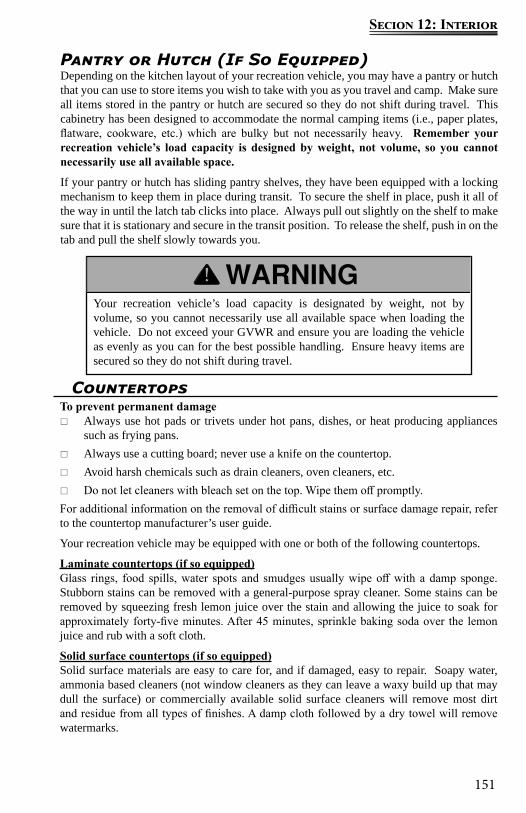
151
Secion 12: Interior
Pantry or Hutch (If So Equipped)Depending on the kitchen layout of your recreation vehicle, you may have a pantry or hutch that you can use to store items you wish to take with you as you travel and camp. Make sure all items stored in the pantry or hutch are secured so they do not shift during travel. This cabinetry has been designed to accommodate the normal camping items (i.e., paper plates, flatware, cookware, etc.) which are bulky but not necessarily heavy. Remember your recreation vehicle’s load capacity is designed by weight, not volume, so you cannot necessarily use all available space.
If your pantry or hutch has sliding pantry shelves, they have been equipped with a locking mechanism to keep them in place during transit. To secure the shelf in place, push it all of the way in until the latch tab clicks into place. Always pull out slightly on the shelf to make sure that it is stationary and secure in the transit position. To release the shelf, push in on the tab and pull the shelf slowly towards you.
Your recreation vehicle’s load capacity is designated by weight, not by volume, so you cannot necessarily use all available space when loading the vehicle. Do not exceed your GVWR and ensure you are loading the vehicle as evenly as you can for the best possible handling. Ensure heavy items are secured so they do not shift during travel.
Countertops To prevent permanent damage
Always use hot pads or trivets under hot pans, dishes, or heat producing appliances such as frying pans.
Always use a cutting board; never use a knife on the countertop. Avoid harsh chemicals such as drain cleaners, oven cleaners, etc. Do not let cleaners with bleach set on the top. Wipe them off promptly.
For additional information on the removal of difficult stains or surface damage repair, refer to the countertop manufacturer’s user guide.
Your recreation vehicle may be equipped with one or both of the following countertops.
Laminate countertops (if so equipped)Glass rings, food spills, water spots and smudges usually wipe off with a damp sponge. Stubborn stains can be removed with a general-purpose spray cleaner. Some stains can be removed by squeezing fresh lemon juice over the stain and allowing the juice to soak for approximately forty-five minutes. After 45 minutes, sprinkle baking soda over the lemon juice and rub with a soft cloth.
Solid surface countertops (if so equipped)Solid surface materials are easy to care for, and if damaged, easy to repair. Soapy water, ammonia based cleaners (not window cleaners as they can leave a waxy build up that may dull the surface) or commercially available solid surface cleaners will remove most dirt and residue from all types of finishes. A damp cloth followed by a dry towel will remove watermarks.
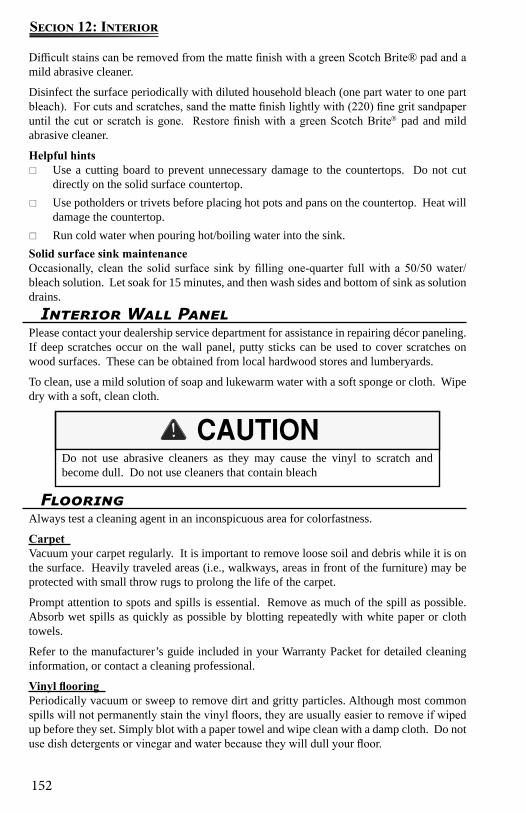
152
Secion 12: Interior
Difficult stains can be removed from the matte finish with a green Scotch Brite® pad and a mild abrasive cleaner.
Disinfect the surface periodically with diluted household bleach (one part water to one part bleach). For cuts and scratches, sand the matte finish lightly with (220) fine grit sandpaper until the cut or scratch is gone. Restore finish with a green Scotch Brite pad and mild abrasive cleaner.
Helpful hints Use a cutting board to prevent unnecessary damage to the countertops. Do not cut
directly on the solid surface countertop. Use potholders or trivets before placing hot pots and pans on the countertop. Heat will
damage the countertop. Run cold water when pouring hot/boiling water into the sink.
Solid surface sink maintenanceOccasionally, clean the solid surface sink by filling one-quarter full with a 50/50 water/bleach solution. Let soak for 15 minutes, and then wash sides and bottom of sink as solution drains.
Do not use abrasive cleaners as they may cause the vinyl to scratch and become dull. Do not use cleaners that contain bleach
Interior Wall PanelPlease contact your dealership service department for assistance in repairing décor paneling. If deep scratches occur on the wall panel, putty sticks can be used to cover scratches on wood surfaces. These can be obtained from local hardwood stores and lumberyards.
To clean, use a mild solution of soap and lukewarm water with a soft sponge or cloth. Wipe dry with a soft, clean cloth.
FlooringAlways test a cleaning agent in an inconspicuous area for colorfastness.
Carpet Vacuum your carpet regularly. It is important to remove loose soil and debris while it is on the surface. Heavily traveled areas (i.e., walkways, areas in front of the furniture) may be protected with small throw rugs to prolong the life of the carpet.
Prompt attention to spots and spills is essential. Remove as much of the spill as possible. Absorb wet spills as quickly as possible by blotting repeatedly with white paper or cloth towels.
Refer to the manufacturer’s guide included in your Warranty Packet for detailed cleaning information, or contact a cleaning professional.
Vinyl flooring Periodically vacuum or sweep to remove dirt and gritty particles. Although most common spills will not permanently stain the vinyl floors, they are usually easier to remove if wiped up before they set. Simply blot with a paper towel and wipe clean with a damp cloth. Do not use dish detergents or vinegar and water because they will dull your floor.
153
Secion 12: Interior
To care for the vinyl floor covering, use a damp mop with water and a mild cleaner on the entire floor. DO NOT SOAK THE FLOORING. Use care to avoid wetting the carpet edges. To avoid problems of “yellowing” linoleum, the flooring manufacturer recommends avoiding cleaners that contain oil based solvents (i.e. cleaners containing lemon oil, Murphy’s Oil Soap, etc.).
Privacy Drape InstallationStarting at the driver’s side of the cab, attach the black plastic hook to the loop attached to the wall behind the driver’s seat. Make sure that the side of the drape with Velcro® is facing the motorhome windshield.
1. Pull the drape toward the front of the motor home and behind the driver’s side sun visor. Open the sun visor against the windshield to hold the drape in place.
2. Proceed across the windshield to the passenger side, again placing the drape behind the sun visor and opening the sun visor to hold the drape in place.
3. Attach the black plastic hook at the passenger’s side of the cab to the loop attached to the wall behind the passenger’s seat.
4. Attach the Velcro® at the top edge of the drape above the driver’s and passenger’s doors to the corresponding Velcro on the roof of the motorhome cab.
5. The Velcro® at the bottom corners of the privacy drape under the black plastic hooks should also be attached to the Velcro on the walls of the motor home in the corresponding locations.
Bed StorageAdditional storage has been provided under the bed. It is equipped with gas struts to assist with easy access. To access the storage area, grasp the end ledge at the foot of the bed and lift carefully. To close, carefully push down on the bed slowly easing it to the closed position.
The bedroom electric slide room system may be located under the bed. Use care not to obstruct the slide room system when using the under bed storage area.
Before lifting, be sure there is nothing on the bed that will restrict its movement or add extra weight. Use caution when opening or closing the bed to keep hands and fingers at the end ledge provided (not on the side or further back than necessary) to avoid pinch points.
ABS PlasticsDust and wipe clean with soft, damp cloth or chamois, wiping gently. Do not use gritty or abrasive particle soaps or scouring compound to clean ABS plastic. Avoid using “citrus” or biodegradable cleaners which contain “D-Limonene” as they may damage plastic materials.
Ceiling FabricThe ceiling fabric is made from padded vinyl fabric. Wash with mild detergent and water. Use a soft bristle brush for stubborn soil. Rinse and dry. Some household cleaners and solvents remove plasticizers from vinyl, making them brittle. Abrasive cleaners may mar or scratch the surface. Always test a small hidden area before applying cleaners to the vinyl surface.

154
Secion 12: Interior
Notes:
155
Section 13: Exterior
Cleaning The ExteriorTo protect your recreation vehicle’s exterior finish, wash it often and thoroughly.
For recreation vehicles with painted exterior graphics: If desired you may wash and wax your vehicle 60 days after purchase. The exterior paint does need time to cure before any wax is applied to the exterior surface. Careful maintenance for the first 60 days will assure a long lasting durable finish.
Your recreation vehicle is exposed to many environmental conditions that have an adverse affect on the paint finish:
Road Salt and Sodium Chloride Road Tar / Bugs Bird Droppings / Tree Sap Industrial Fallout / Acid Rain /Pollution UV Exposure and Moisture
The most common problems resulting from these conditions are corrosion, staining, and chemical spotting. Generally, the longer the foreign material remains in contact with the exterior finish, the more extensive the damage. These problems can be minimized by regularly scheduled washing and polishing. Wash your recreation vehicle as soon as possible if it becomes contaminated with foreign material.
Avoid parking under trees or near ocean sea salt. Ice or snow should not be scraped from the painted surface: Brush off!
Gravel roads should be avoided. Anti-freeze, gasoline or washer solvents if spilled on the painted surface should be rinsed off with water immediately. Bugs and bird droppings should be rinsed off daily.
WashingCommercial washing should be avoided. Wash with cold water using a mild liquid soap. Dry wiping with a dry cloth is not recommended.
Make sure the recreation vehicle’s surface temperature is cool, under 90 F, and out of direct sunlight. A shaded area is ideal for washing your vehicle as direct sunlight causes water spotting. Use a mild soap or detergent. Most auto care stores will carry a car wash shampoo. Try to avoid combination wash-n-wax products as these waxes can cause build up and are designed for smaller surfaces. Have two dedicated sponges or wash mitts: one for the exterior walls and one for the wheels and under- carriage. Brushes or wash mitts that are made of plastic bristles are acceptable for use on tires and wheel wells, but are not intended for use on the exterior walls. Avoid using such items on painted surfaces as they will damage the finish. Wash the wheels and wheel wells first as this removes heavy dirt and debris and prevents it from splattering on panels. Wet the entire area down to remove loose dirt and grime, then hand wash one area at a time using your dedicated paint finish sponge or wash mitt.
Wash from the top and work your way down, rinsing frequently to minimize grit abrasion. Follow with a final rinse of water. This process will remove most contamination from the recreation vehicle’s surface. For stubborn stains such as road tar or bug stains, use an ammonia based glass cleaner or a small amount of rubbing alcohol on a damp cloth followed immediately by warm soapy water, and rinsing with clean water.
This may not dissolve the road tar, but it will loosen tar and bug stains and remove them
156
Section 13: Exterior
Do not use waxes containing high-abrasive compounds. Such waxes remove rust and stains effectively from the paint work, but they are also harmful to the luster of the painted surface since they scrape off the coating. Further, they are detrimental to glossy surfaces, such as the grille, garnish, moldings, etc. do not use gasoline or paint thinners to remove road tar or other contamination to the painted surface.
NOTE: When the slideout or door is frozen, opening it by force may tear off or crack the rubber gasket that is installed around the slideout or door. Therefore, pour warm water on the gasket to melt the ice (wipe off the water thoroughly after opening the slideout or door). To prevent the weather stripping from freezing, treat it with a silicone spray.
from the surface. Do not use solvent based cleaners on bird droppings or tree sap as these are water based stains. They can be dissolved using ammonia based glass cleaner, warm soapy water and a little “elbow grease”. Once again, after removing stubborn stains immediately rinse with clean water.
Drying the recreation vehicle is just as important as washing your vehicle. Tap and well water contain many chemicals that could water stain your vehicle’s finish. We suggest using a damp natural or synthetic chamois. There are other drying products such as lint-free micro-fiber towels that work just as well.
During cold weatherSalt and other chemicals that are spread on winter roads in some geographical areas can have a detrimental effect on the recreation vehicle’s underbody. If your recreation vehicle is exposed to these conditions, spray the underbody with a high-pressure hose every time you wash the exterior of your recreation vehicle.
Take special care to remove mud or other debris that could trap and hold salt or moisture. After washing your recreation vehicle, wipe off all water drops from the rubber parts around the slideout and doors.
Waxing Wax your recreation vehicle once or twice a year, or when painted surfaces do not shed water well. Use a soft cloth to apply a small amount of wax to the painted surfaces. After the wax has dried, polish the recreation vehicle with a dry, soft cloth. Do not wax your recreation vehicle in direct sunlight. Wax it after the surfaces have cooled.
Do not apply wax to any area having a flat black finish as it can cause discoloration. If the finish has been stained with wax, wipe off the area with a soft cloth and warm water. When waxing the area around the various openings, do not apply any wax on the weather-strip. If it is stained with wax, the weather-strip cannot maintain a weatherproof seal around the opening.
157
Section 13: Exterior
Polishing your recreation vehicleIf painted surfaces have been severely damaged and have lost their original luster and color tone, polish the surface lightly with a fine polishing compound. Avoid limiting your polishing to the damaged surface only; polish a somewhat wider area, moving the polishing cloth in one direction. After polishing, flush the compound from the surface and apply a coat of wax to regain a beautiful luster.
Damaged paintTo prevent corrosion, touch up small cracks and scratches in the paint coat as soon as possible with touch-up film or paint. Carefully check the body areas facing the road and the tires for damage to the paint coat caused by flying stones, etc. To purchase touch-up paint, use the closest automotive paint (available locally) match possible.
Cleaning plastic partsUse a sponge or chamois to clean plastic parts. Use warm water and a soft cloth or chamois to remove any white residue from dark colored plastic surfaces. Do not use a scrubbing brush, other hard tools, or wax containing abrasives as they may damage the plastic surface.
Chrome partsTo prevent chrome parts from spotting or corroding, wash with water, dry thoroughly, and apply a non-abrasive automotive wax. If the chrome is severely damaged or pitted, use a commercially available chrome polish product.
Do not use a buffer and a buffing compound as it may damage the exterior surface. Please contact a professional paint body shop for assistance.
Do not allow plastic to come into contact with brake fluid, engine oil, grease, paint thinner, or batter acid. These will damage plastic. Use a soft cloth and a mild detergent solution to wipe away any such contact..
FrameSand, pebbles, objects on the highway, climate (salt air exposure) or ice inhibiting chemicals used during the winter months will damage the paint, inviting rust and other deterioration. Periodically inspect the exterior exposed areas, clean and repaint the frame members occasionally and whenever you notice rust or paint chipped away, to insure protection.
Chassis Maintenance Refer to your Chassis Guide for detailed safety and maintenance instructions.
Front Axle Tire AlignmentThe term alignment refers to both the adjustment angles on the steering axle and suspension and tracking of the rear axle. Many factors are considered when establishing proper alignment. Steering components, suspension, wheel bearings and even proper loading will affect your motor home alignment. Your motor home chassis was aligned by the manufacturer, and weighed at our facility before shipment to your dealer. It is your responsibility to have

158
Section 13: Exterior
Windows
Any ventilating window may permit water inside, especially during heavy rainstorms or while driving. This is normal and water should only be seen in the lower track portion of the window frame. Condensation will also cause water to accumulate on windows and in the tracks. Ensure that the escape window latches are properly adjusted (the window will pop open if not adjusted tight enough).
Window glassThe window glass can normally be cleaned with a sponge and water. Use glass cleaner to remove wax, oil, grease, dead insects, etc. After washing the glass, wipe it dry with a clean, soft cloth.
To avoid exhaust gas entry into the motor home, keep windows closed when the chassis or generator engines are running.
the alignment inspected periodically to maintain vehicle steering performance and prevent uneven tire wear as part of your normal maintenance.
NOTE: Always have the alignment checked and adjusted by a qualified shop with the proper equipment to handle heavy vehicles.
NOTE: A road test by the dealer should be included as part of the pre-delivery inspection. The dealer can check for and correct any steering problems before you take delivery of the motor home. After this road test has been completed, front-end alignment and/or vibra-tions will not be covered as part of the new vehicle limited warranty.
Exterior Roof & Sidewall VentsWhile you are cleaning the exterior roof assembly, also inspect the roof vents (including sealants) for cracks and keep them clean. Inspect the refrigerator and holding tank vents for blockages from bird nests, spider webs, leaves, etc. All exterior access doors and vents need to be kept clean and free of obstructions (i.e., insect nests, mud daubers, etc.) while the appliances are in use.
Exterior ladder (If So Equipped)Your recreation vehicle may be equipped with an optional roof ladder. The recreation vehicle roof has decking under the rubber roof membrane to allow you to walk on the roof (with caution) to do maintenance.
159
Section 13: Exterior
To check the exterior sidewall sealants, use a stepladder placed safely alongside the vehicle. Do not prop a ladder against the body of the motor home as it may damage the exterior finish
SealantsSealants perform a very important function and should be inspected closely and regularly maintained. We incorporate many different types of sealants, including butyl/putty, black butyl-encapsulated foam, silicone (clear and colored), roof sealant and foam. In general, sealants do not have “set” lifetimes. Varying environmental factors affect the pliability and adhesiveness of sealants.
You or your dealer must:
Inspect all sealants, a minimum of every six months. A quick walk around the motor home before leaving may help prevent potential problems during trips and vacations.
Have the sealant replaced if you notice any cracks, voids, gaps, breaks, looseness or any sign of physical deterioration.
Always use the same type of sealant that was removed. Your dealer service or parts manager can help you obtain the correct sealant(s).
The sealants may become damaged due to ultraviolet exposure, air pollution, freezing temperatures and exposure to other elements. If deteriorated, repair immediately to prevent damage. Cap seal all trim and openings at least once after the first year and thereafter as cracks, peeling, lifting and shrinkage occur. Conditions such as rain, salt, dust and pollution may increase your vehicle maintenance needs.
If your recreation vehicle is equipped with a roof ladder, do not leave items attached to it while traveling. The ladder weight capacity should not be exceeded (see ladder capacity label). DO NOT exceed this weight limit. There should never be more than one person on the ladder at the same time.

160
Section 13: Exterior
Notes:
161
Section 14: Travel/Camping/Storage Checklists
RV Start-UpThe following checklist will help ensure a trouble-free camping and travel season:
Inspect and work all interior and exterior latches and locks (lube if necessary). Make sure the batteries are fully charged and installed correctly. Turn ON the motor home 12-volt battery disconnect switch. Inspect the power cord and carefully clean the contacts if necessary. Plug in the power
cord to an appropriate power source. Turn on the interior lights and check outlets for polarity. If needed, replace any blown
fuses. Check the circuit breakers and test the GFCI circuits. Inspect and turn on the LP gas system (if so equipped). If you have any questions,
contact your independent dealer or a qualified LP gas service representative for assistance. If the propane system is functioning properly, test any pilot lights or direct spark ignition features.
Inspect and test all safety detectors. If needed, replace any drained or discharged batteries. If you have a defective or damaged safety detector, replace it immediately.
Inspect the leveling jacks for operation. If needed, perform maintenance as per the manufacturer’s information.
Test all exterior and interior lights. Replace any bulbs that are burnt out. Prepare the chassis portion of the motor home for the camping season in accordance
with the Chassis Guide. Inspect the tires for wear, cracks and inflation pressure. Wash the exterior of the motor home. Do a sealant inspection and repair as necessary. De-winterize and sanitize system according to the instructions in Sec. 8 Plumbing
Section. If you are towing a vehicle, connect it to the motor home and test all connections and
lights.
Ready To Leave ChecklistFollowing is a preliminary list of items that need to be checked before leaving your home or campsite. This is a general list, which you may want to customize as you determine your own needs. Refer to your Chassis Guide for information on chassis pre-trip inspections and maintenance.
Check the area under the motor home after overnight parking and look for fuel, water, oil or other fluid leaks. If leaks are detected, find the cause and correct it immediately.
Make sure all fluids are at proper levels. Check the engine oil, transmission fluid, engine coolant, power steering fluid and windshield washer fluid.
Check the fuel gauge and lights on the motor home. Have someone observe the operation of all exterior lights while you activate the controls. Check the turn signal and high beam indicators on the instrument panel.
Examine the tires for excessive tread wear or uneven wear patterns. Check for stones, nails, glass or other objects lodged in the tread. Inspect for tread cuts or sidewall cracks.
Check wheel nuts for tightness and tires for proper air inflation pressure.
162
Section 14: Travel/Camping/Storage Checklists
Motor home StorageProperly preparing your motor home for storage during periods of non-usage will prevent problems from arising. It will also make it easier to get started again for the following camping trip or season. To prevent costly freeze-ups, winterize the plumbing system when it will not be in use for an extended period of time, especially if it is stored in colder climates.
Prepare the chassis for storage in accordance to the Chassis Guide. Remember to use fuel additives and supplements if so recommended.
Wash and wax the exterior of the vehicle. Do a sealant inspection and repair as necessary.
Adding fuel stabilizer to the generator will aid in preventing condensation and fuel varnishing.
Test brakes for proper operation Check the propane tank gauge (if so equipped) to make sure there is propane available.
Turn off propane tanks. Empty black and gray holding tank, rinse as needed If needed, sanitize the fresh water system. Fill the fresh water tank. Disconnect, drain and store the garden hose on the bracket. Retract any awnings and secure them for transport. Close all the roof vents. Close windows & latch blinds Disconnect the cable TV and phone hookups and lower the TV antenna. Turn off the interior lights, water heater, furnace and water pump. Secure any loose, heavy or sharp objects in the motor home or exterior compartments. Disconnect the power cord and ensure it is stored correctly. Disconnect any water connections. Water pump and water heater (if applicable) turned off Fasten all interior and exterior doors securely. Lock them (if applicable) Latch drawers,
cabinets & doors Make sure the leveling jacks are retracted to the travel position. Walk around your motor home one last time to make sure everything is stored away and
the baggage compartments are closed and locked. Refrigerator door locked Furnace turned off Check the seat belt buckles and release mechanisms for positive action and secure
connections Move slideout(s) in and lock it in place (if applicable). Retract step Secure and lock the entrance door.
Safety Make sure you follow all safety precautions noted in this owner’s manual and in any
manufacturer’s operators manual when preparing to travel.
163
Section 14: Travel/Camping/Storage Checklists
Inspect and clean tires. Check for wear, cracks and inflation pressure. Inspect under the motor home for any openings into the floor where animals or insects
may enter and seal if necessary. Turn the furnace thermostat(s) to the OFF position. If your motor home is equipped with a gas/electric DSI range, light a range gas burner
to consume any gas remaining in the lines. Once the flame extinguishes itself, turn the burner valve OFF.
You may want to place rodent control products in the vehicle during storage. Rodents can do damage to the interior components, particularly during the winter months.
Remove all perishables from the refrigerator/freezer. Defrost, wash and dry the interior of the refrigerator/freezer and prop (or block) the doors open so air can circulate and prevent mildew.
Remove all perishables from the cabinets. Leave the cabinets and doors ajar to allow air circulation and prevent mildew and musty odors.
Lubricate locks and hinges on exterior doors. Turn OFF the motor home 12-volt battery disconnect switch. Turn OFF the inverter mode at remote. Disconnect the batteries to prevent battery discharge. While the motor home is being stored
If the vehicle is stored outside in areas of heavy snow, you should periodically brush the snow off to prevent excessive accumulation and prevent possible roof damage.
Periodically inspect your motor home during storage, and seal off any area that can offer an entry point for rodents, birds or insects. Also inspect the motor home for any damage.
Damage from birds, rodents, insects, etc., is not covered under the “Motorized Transferable Limited Warranty” applicable to your motor home.

164
Section 14: Travel/Camping/Storage Checklists
Notes:
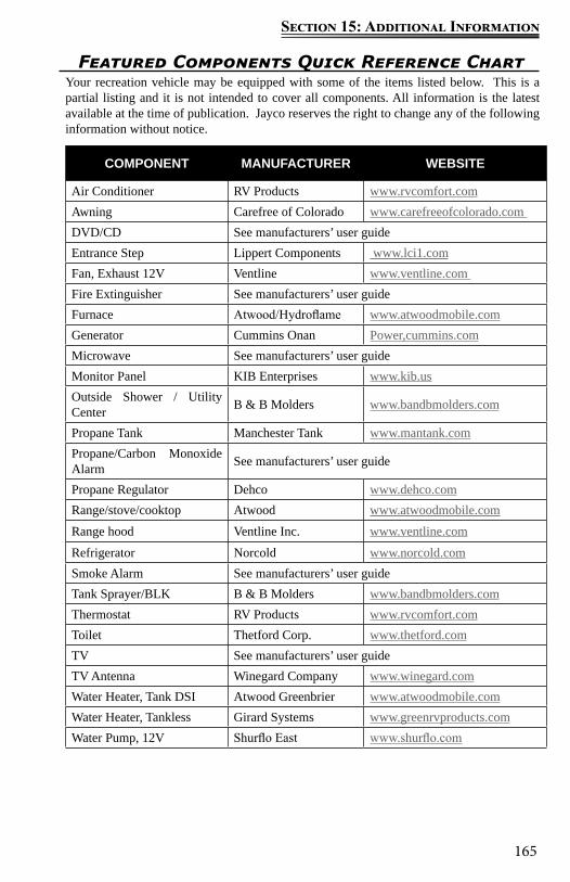
165
Section 15: Additional Information
Featured Components Quick Reference ChartYour recreation vehicle may be equipped with some of the items listed below. This is a partial listing and it is not intended to cover all components. All information is the latest available at the time of publication. Jayco reserves the right to change any of the following information without notice.
COMPONENT MANUFACTURER WEBSITE
Air Conditioner RV Products www.rvcomfort.comAwning Carefree of Colorado www.carefreeofcolorado.com DVD/CD See manufacturers’ user guideEntrance Step Lippert Components www.lci1.comFan, Exhaust 12V Ventline www.ventline.com Fire Extinguisher See manufacturers’ user guideFurnace Atwood/Hydroflame www.atwoodmobile.comGenerator Cummins Onan Power,cummins.comMicrowave See manufacturers’ user guideMonitor Panel KIB Enterprises www.kib.usOutside Shower / Utility Center B & B Molders www.bandbmolders.com
Propane Tank Manchester Tank www.mantank.comPropane/Carbon Monoxide Alarm See manufacturers’ user guide
Propane Regulator Dehco www.dehco.comRange/stove/cooktop Atwood www.atwoodmobile.comRange hood Ventline Inc. www.ventline.comRefrigerator Norcold www.norcold.comSmoke Alarm See manufacturers’ user guideTank Sprayer/BLK B & B Molders www.bandbmolders.comThermostat RV Products www.rvcomfort.comToilet Thetford Corp. www.thetford.comTV See manufacturers’ user guideTV Antenna Winegard Company www.winegard.comWater Heater, Tank DSI Atwood Greenbrier www.atwoodmobile.comWater Heater, Tankless Girard Systems www.greenrvproducts.comWater Pump, 12V Shurflo East www.shurflo.com
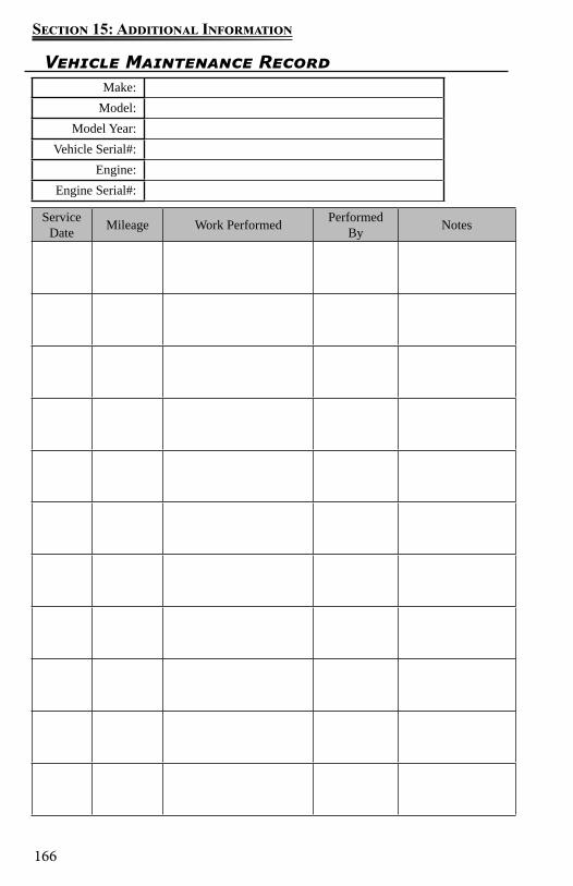
166
Section 15: Additional Information
Vehicle Maintenance RecordMake:
Model:Model Year:
Vehicle Serial#:Engine:
Engine Serial#:
Service Date Mileage Work Performed Performed
By Notes

167
Section 15: Additional Information
Service Date Mileage Work Performed Performed
By Notes

168
Section 15: Additional Information
Notes:
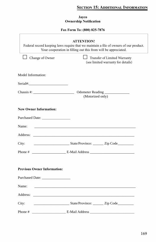
169
Section 15: Additional Information
JaycoOwnership Notification
Fax Form To: (800) 825-7876
□ Change of Owner □ Transfer of Limited Warranty (see limited warranty for details)
Model Information:
Serial#:______________________
Chassis #: _______________________ Odometer Reading ______________ (Motorized only)
New Owner Information:
Purchased Date: ________________
Name: _________________________________________________________
Address: _________________________________________________________
City: ____________________ State/Province: ______ Zip Code_________
Phone # ___________________ E-Mail Address _________________________
Previous Owner Information:
Purchased Date: ________________
Name: _________________________________________________________
Address: _________________________________________________________
City: ____________________ State/Province: ______ Zip Code_________
Phone # ___________________ E-Mail Address _________________________
ATTENTION!Federal record keeping laws require that we maintain a file of owners of our product.
Your cooperation in filling out this from will be appreciated.

170
Section 15: Additional Information
Notes:

171
Section 15: Additional Information
Notes: