Class 5010 Text - Steven Engineeringstevenengineering.com/Tech_Support/PDFs/45CRNE.pdf• Reversing...
164
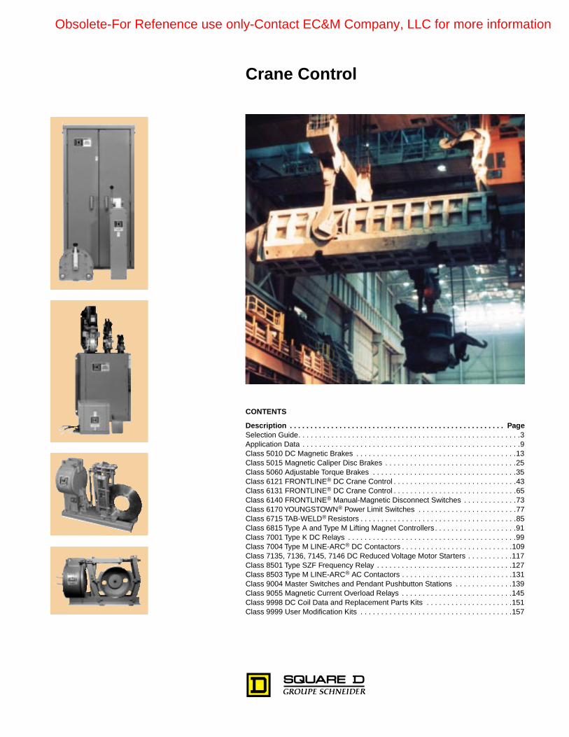
CONTENTS Description . . . . . . . . . . . . . . . . . . . . . . . . . . . . . . . . . . . . . . . . . . . . . . . . . . . . Page Selection Guide. . . . . . . . . . . . . . . . . . . . . . . . . . . . . . . . . . . . . . . . . . . . . . . . . . . . . . 3 Application Data . . . . . . . . . . . . . . . . . . . . . . . . . . . . . . . . . . . . . . . . . . . . . . . . . . . . . 9 Class 5010 DC Magnetic Brakes . . . . . . . . . . . . . . . . . . . . . . . . . . . . . . . . . . . . . . . 13 Class 5015 Magnetic Caliper Disc Brakes . . . . . . . . . . . . . . . . . . . . . . . . . . . . . . . . 25 Class 5060 Adjustable Torque Brakes . . . . . . . . . . . . . . . . . . . . . . . . . . . . . . . . . . . 35 Class 6121 FRONTLINE ® DC Crane Control . . . . . . . . . . . . . . . . . . . . . . . . . . . . . . 43 Class 6131 FRONTLINE ® DC Crane Control . . . . . . . . . . . . . . . . . . . . . . . . . . . . . . 65 Class 6140 FRONTLINE ® Manual-Magnetic Disconnect Switches . . . . . . . . . . . . . 73 Class 6170 YOUNGSTOWN ® Power Limit Switches . . . . . . . . . . . . . . . . . . . . . . . . 77 Class 6715 TAB-WELD ® Resistors . . . . . . . . . . . . . . . . . . . . . . . . . . . . . . . . . . . . . . 85 Class 6815 Type A and Type M Lifting Magnet Controllers . . . . . . . . . . . . . . . . . . . . 91 Class 7001 Type K DC Relays . . . . . . . . . . . . . . . . . . . . . . . . . . . . . . . . . . . . . . . . . 99 Class 7004 Type M LINE-ARC ® DC Contactors . . . . . . . . . . . . . . . . . . . . . . . . . . . 109 Class 7135, 7136, 7145, 7146 DC Reduced Voltage Motor Starters . . . . . . . . . . . 117 Class 8501 Type SZF Frequency Relay . . . . . . . . . . . . . . . . . . . . . . . . . . . . . . . . . 127 Class 8503 Type M LINE-ARC ® AC Contactors . . . . . . . . . . . . . . . . . . . . . . . . . . . 131 Class 9004 Master Switches and Pendant Pushbutton Stations . . . . . . . . . . . . . . 139 Class 9055 Magnetic Current Overload Relays . . . . . . . . . . . . . . . . . . . . . . . . . . . 145 Class 9998 DC Coil Data and Replacement Parts Kits . . . . . . . . . . . . . . . . . . . . . 151 Class 9999 User Modification Kits . . . . . . . . . . . . . . . . . . . . . . . . . . . . . . . . . . . . . 157 Crane Control Obsolete-For Refenence use only-Contact EC&M Company, LLC for more information
Transcript of Class 5010 Text - Steven Engineeringstevenengineering.com/Tech_Support/PDFs/45CRNE.pdf• Reversing...
CONTENTS
Description . . . . . . . . . . . . . . . . . . . . . . . . . . . . . . . . . . . . . . . . . . . . . . . . . . . . Page
Selection Guide. . . . . . . . . . . . . . . . . . . . . . . . . . . . . . . . . . . . . . . . . . . . . . . . . . . . . .3Application Data . . . . . . . . . . . . . . . . . . . . . . . . . . . . . . . . . . . . . . . . . . . . . . . . . . . . .9Class 5010 DC Magnetic Brakes . . . . . . . . . . . . . . . . . . . . . . . . . . . . . . . . . . . . . . .13Class 5015 Magnetic Caliper Disc Brakes . . . . . . . . . . . . . . . . . . . . . . . . . . . . . . . .25Class 5060 Adjustable Torque Brakes . . . . . . . . . . . . . . . . . . . . . . . . . . . . . . . . . . .35Class 6121 FRONTLINE
®
DC Crane Control . . . . . . . . . . . . . . . . . . . . . . . . . . . . . .43Class 6131 FRONTLINE
®
DC Crane Control . . . . . . . . . . . . . . . . . . . . . . . . . . . . . .65Class 6140 FRONTLINE
®
Manual-Magnetic Disconnect Switches . . . . . . . . . . . . .73Class 6170 YOUNGSTOWN
®
Power Limit Switches . . . . . . . . . . . . . . . . . . . . . . . .77Class 6715 TAB-WELD
®
Resistors . . . . . . . . . . . . . . . . . . . . . . . . . . . . . . . . . . . . . .85Class 6815 Type A and Type M Lifting Magnet Controllers. . . . . . . . . . . . . . . . . . . .91Class 7001 Type K DC Relays . . . . . . . . . . . . . . . . . . . . . . . . . . . . . . . . . . . . . . . . .99Class 7004 Type M LINE-ARC
®
DC Contactors . . . . . . . . . . . . . . . . . . . . . . . . . . .109Class 7135, 7136, 7145, 7146 DC Reduced Voltage Motor Starters . . . . . . . . . . .117Class 8501 Type SZF Frequency Relay . . . . . . . . . . . . . . . . . . . . . . . . . . . . . . . . .127Class 8503 Type M LINE-ARC
®
AC Contactors . . . . . . . . . . . . . . . . . . . . . . . . . . .131Class 9004 Master Switches and Pendant Pushbutton Stations . . . . . . . . . . . . . .139Class 9055 Magnetic Current Overload Relays . . . . . . . . . . . . . . . . . . . . . . . . . . .145Class 9998 DC Coil Data and Replacement Parts Kits . . . . . . . . . . . . . . . . . . . . .151Class 9999 User Modification Kits . . . . . . . . . . . . . . . . . . . . . . . . . . . . . . . . . . . . .157
Crane Control
Obsolete-For Refenence use only-Contact EC&M Company, LLC for more information

© 1998 Square D All Rights Reserved
2
7/98
Crane Control Selection Guide
7/98
SE
LE
CT
ION
GU
IDE
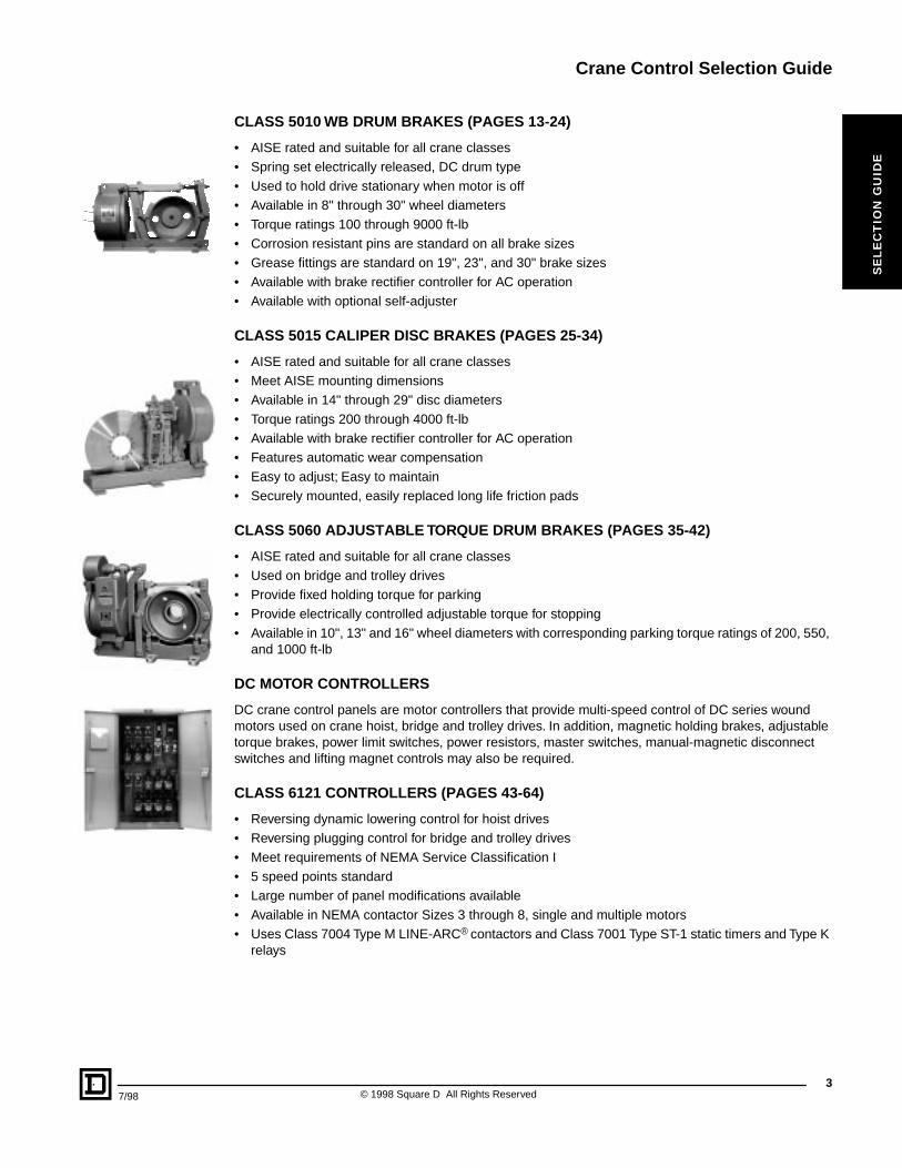
CLASS 5010 WB DRUM BRAKES (PAGES 13-24)
• AISE rated and suitable for all crane classes• Spring set electrically released, DC drum type• Used to hold drive stationary when motor is off• Available in 8" through 30" wheel diameters• Torque ratings 100 through 9000 ft-lb• Corrosion resistant pins are standard on all brake sizes• Grease fittings are standard on 19", 23", and 30" brake sizes• Available with brake rectifier controller for AC operation• Available with optional self-adjuster
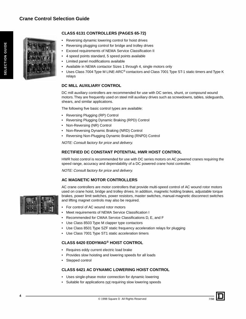
CLASS 5015 CALIPER DISC BRAKES (PAGES 25-34)
• AISE rated and suitable for all crane classes• Meet AISE mounting dimensions• Available in 14" through 29" disc diameters• Torque ratings 200 through 4000 ft-lb• Available with brake rectifier controller for AC operation• Features automatic wear compensation• Easy to adjust; Easy to maintain• Securely mounted, easily replaced long life friction pads
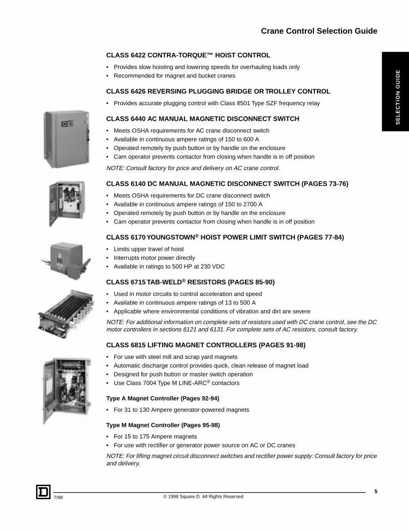
CLASS 5060 ADJUSTABLE TORQUE DRUM BRAKES (PAGES 35-42)
• AISE rated and suitable for all crane classes• Used on bridge and trolley drives• Provide fixed holding torque for parking• Provide electrically controlled adjustable torque for stopping• Available in 10", 13" and 16" wheel diameters with corresponding parking torque ratings of 200, 550,
and 1000 ft-lb
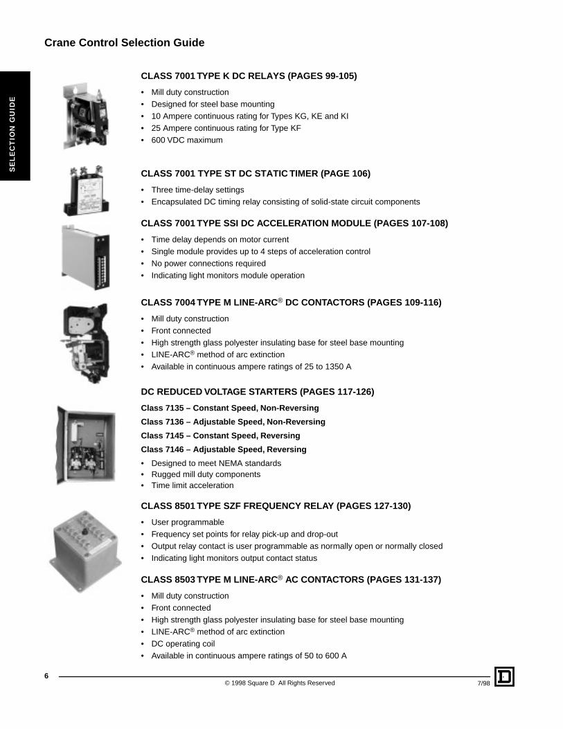
DC MOTOR CONTROLLERS
DC crane control panels are motor controllers that provide multi-speed control of DC series wound motors used on crane hoist, bridge and trolley drives. In addition, magnetic holding brakes, adjustable torque brakes, power limit switches, power resistors, master switches, manual-magnetic disconnect switches and lifting magnet controls may also be required.
CLASS 6121 CONTROLLERS (PAGES 43-64)
• Reversing dynamic lowering control for hoist drives• Reversing plugging control for bridge and trolley drives• Meet requirements of NEMA Service Classification I• 5 speed points standard• Large number of panel modifications available• Available in NEMA contactor Sizes 3 through 8, single and multiple motors• Uses Class 7004 Type M LINE-ARC® contactors and Class 7001 Type ST-1 static timers and Type K
relays
3© 1998 Square D All Rights Reserved
Crane Control Selection Guide
4
SE
LE
CT
ION
GU
IDE
CLASS 6131 CONTROLLERS (PAGES 65-72)
• Reversing dynamic lowering control for hoist drives • Reversing plugging control for bridge and trolley drives• Exceed requirements of NEMA Service Classification II• 4 speed points standard, 5 speed points available• Limited panel modifications available• Available in NEMA contactor Sizes 1 through 4, single motors only• Uses Class 7004 Type M LINE-ARC® contactors and Class 7001 Type ST-1 static timers and Type K
relays
DC MILL AUXILIARY CONTROL
DC mill auxiliary controllers are recommended for use with DC series, shunt, or compound wound motors. They are frequently used on steel mill auxiliary drives such as screwdowns, tables, sideguards, shears, and similar applications.
The following five basic control types are available:
• Reversing Plugging (RP) Control• Reversing Plugging Dynamic Braking (RPD) Control• Non-Reversing (NR) Control• Non-Reversing Dynamic Braking (NRD) Control• Reversing Non-Plugging Dynamic Braking (RNPD) Control
NOTE: Consult factory for price and delivery.
RECTIFIED DC CONSTANT POTENTIAL HWR HOIST CONTROL
HWR hoist control is recommended for use with DC series motors on AC powered cranes requiring the speed range, accuracy and dependability of a DC powered crane hoist controller.
NOTE: Consult factory for price and delivery.
AC MAGNETIC MOTOR CONTROLLERS
AC crane controllers are motor controllers that provide multi-speed control of AC wound rotor motors used on crane hoist, bridge and trolley drives. In addition, magnetic holding brakes, adjustable torque brakes, power limit switches, power resistors, master switches, manual-magnetic disconnect switches and lifting magnet controls may also be required.
• For control of AC wound rotor motors• Meet requirements of NEMA Service Classification I• Recommended for CMAA Service Classifications D, E, and F• Use Class 8503 Type M clapper type contactors• Use Class 8501 Type SZF static frequency acceleration relays for plugging• Use Class 7001 Type ST1 static acceleration timers
CLASS 6420 EDDYMAG® HOIST CONTROL
• Requires eddy current electric load brake• Provides slow hoisting and lowering speeds for all loads• Stepped control
CLASS 6421 AC DYNAMIC LOWERING HOIST CONTROL
• Uses single-phase motor connection for dynamic lowering• Suitable for applications not requiring slow lowering speeds
© 1998 Square D All Rights Reserved 7/98
Crane Control Selection Guide
7/98
SE
LE
CT
ION
GU
IDE
CLASS 6422 CONTRA-TORQUE™ HOIST CONTROL
• Provides slow hoisting and lowering speeds for overhauling loads only• Recommended for magnet and bucket cranes
CLASS 6426 REVERSING PLUGGING BRIDGE OR TROLLEY CONTROL
• Provides accurate plugging control with Class 8501 Type SZF frequency relay
CLASS 6440 AC MANUAL MAGNETIC DISCONNECT SWITCH
• Meets OSHA requirements for AC crane disconnect switch• Available in continuous ampere ratings of 150 to 600 A• Operated remotely by push button or by handle on the enclosure• Cam operator prevents contactor from closing when handle is in off position
NOTE: Consult factory for price and delivery on AC crane control.
CLASS 6140 DC MANUAL MAGNETIC DISCONNECT SWITCH (PAGES 73-76)
• Meets OSHA requirements for DC crane disconnect switch• Available in continuous ampere ratings of 150 to 2700 A• Operated remotely by push button or by handle on the enclosure• Cam operator prevents contactor from closing when handle is in off position
CLASS 6170 YOUNGSTOWN® HOIST POWER LIMIT SWITCH (PAGES 77-84)
• Limits upper travel of hoist• Interrupts motor power directly• Available in ratings to 500 HP at 230 VDC
CLASS 6715 TAB-WELD® RESISTORS (PAGES 85-90)
• Used in motor circuits to control acceleration and speed• Available in continuous ampere ratings of 13 to 500 A• Applicable where environmental conditions of vibration and dirt are severe
NOTE: For additional information on complete sets of resistors used with DC crane control, see the DC motor controllers in sections 6121 and 6131. For complete sets of AC resistors, consult factory.
CLASS 6815 LIFTING MAGNET CONTROLLERS (PAGES 91-98)
• For use with steel mill and scrap yard magnets• Automatic discharge control provides quick, clean release of magnet load• Designed for push button or master switch operation• Use Class 7004 Type M LINE-ARC® contactors
Type A Magnet Controller (Pages 92-94)
• For 31 to 130 Ampere generator-powered magnets
Type M Magnet Controller (Pages 95-98)
• For 15 to 175 Ampere magnets• For use with rectifier or generator power source on AC or DC cranes
NOTE: For lifting magnet circuit disconnect switches and rectifier power supply: Consult factory for price and delivery.
5© 1998 Square D All Rights Reserved
Crane Control Selection Guide
6
SE
LE
CT
ION
GU
IDE
CLASS 7001 TYPE K DC RELAYS (PAGES 99-105)
• Mill duty construction• Designed for steel base mounting• 10 Ampere continuous rating for Types KG, KE and KI• 25 Ampere continuous rating for Type KF• 600 VDC maximum
CLASS 7001 TYPE ST DC STATIC TIMER (PAGE 106)
• Three time-delay settings• Encapsulated DC timing relay consisting of solid-state circuit components
CLASS 7001 TYPE SSI DC ACCELERATION MODULE (PAGES 107-108)
• Time delay depends on motor current• Single module provides up to 4 steps of acceleration control• No power connections required • Indicating light monitors module operation
CLASS 7004 TYPE M LINE-ARC® DC CONTACTORS (PAGES 109-116)
• Mill duty construction• Front connected• High strength glass polyester insulating base for steel base mounting• LINE-ARC® method of arc extinction• Available in continuous ampere ratings of 25 to 1350 A
DC REDUCED VOLTAGE STARTERS (PAGES 117-126)
Class 7135 – Constant Speed, Non-Reversing
Class 7136 – Adjustable Speed, Non-Reversing
Class 7145 – Constant Speed, Reversing
Class 7146 – Adjustable Speed, Reversing
• Designed to meet NEMA standards• Rugged mill duty components• Time limit acceleration
CLASS 8501 TYPE SZF FREQUENCY RELAY (PAGES 127-130)
• User programmable• Frequency set points for relay pick-up and drop-out• Output relay contact is user programmable as normally open or normally closed• Indicating light monitors output contact status
CLASS 8503 TYPE M LINE-ARC® AC CONTACTORS (PAGES 131-137)
• Mill duty construction• Front connected• High strength glass polyester insulating base for steel base mounting• LINE-ARC® method of arc extinction• DC operating coil• Available in continuous ampere ratings of 50 to 600 A
© 1998 Square D All Rights Reserved 7/98
Crane Control Selection Guide
7/98
SE
LE
CT
ION
GU
IDE
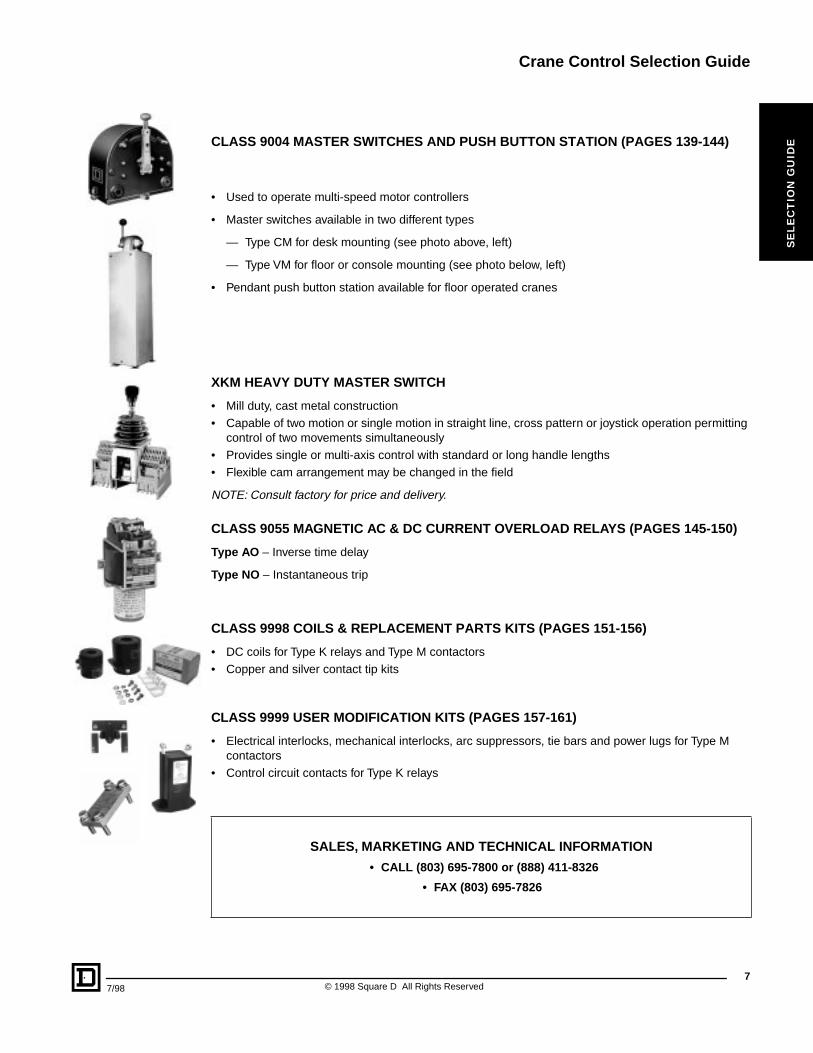
CLASS 9004 MASTER SWITCHES AND PUSH BUTTON STATION (PAGES 139-144)
• Used to operate multi-speed motor controllers
• Master switches available in two different types
— Type CM for desk mounting (see photo above, left)
— Type VM for floor or console mounting (see photo below, left)
• Pendant push button station available for floor operated cranes
XKM HEAVY DUTY MASTER SWITCH
• Mill duty, cast metal construction• Capable of two motion or single motion in straight line, cross pattern or joystick operation permitting
control of two movements simultaneously• Provides single or multi-axis control with standard or long handle lengths• Flexible cam arrangement may be changed in the field
NOTE: Consult factory for price and delivery.
CLASS 9055 MAGNETIC AC & DC CURRENT OVERLOAD RELAYS (PAGES 145-150)
Type AO – Inverse time delay
Type NO – Instantaneous trip
CLASS 9998 COILS & REPLACEMENT PARTS KITS (PAGES 151-156)
• DC coils for Type K relays and Type M contactors• Copper and silver contact tip kits
CLASS 9999 USER MODIFICATION KITS (PAGES 157-161)
• Electrical interlocks, mechanical interlocks, arc suppressors, tie bars and power lugs for Type M contactors
• Control circuit contacts for Type K relays
SALES, MARKETING AND TECHNICAL INFORMATION
• CALL (803) 695-7800 or (888) 411-8326
• FAX (803) 695-7826
7© 1998 Square D All Rights Reserved
Crane Control Selection Guide
8
SE
LE
CT
ION
GU
IDE
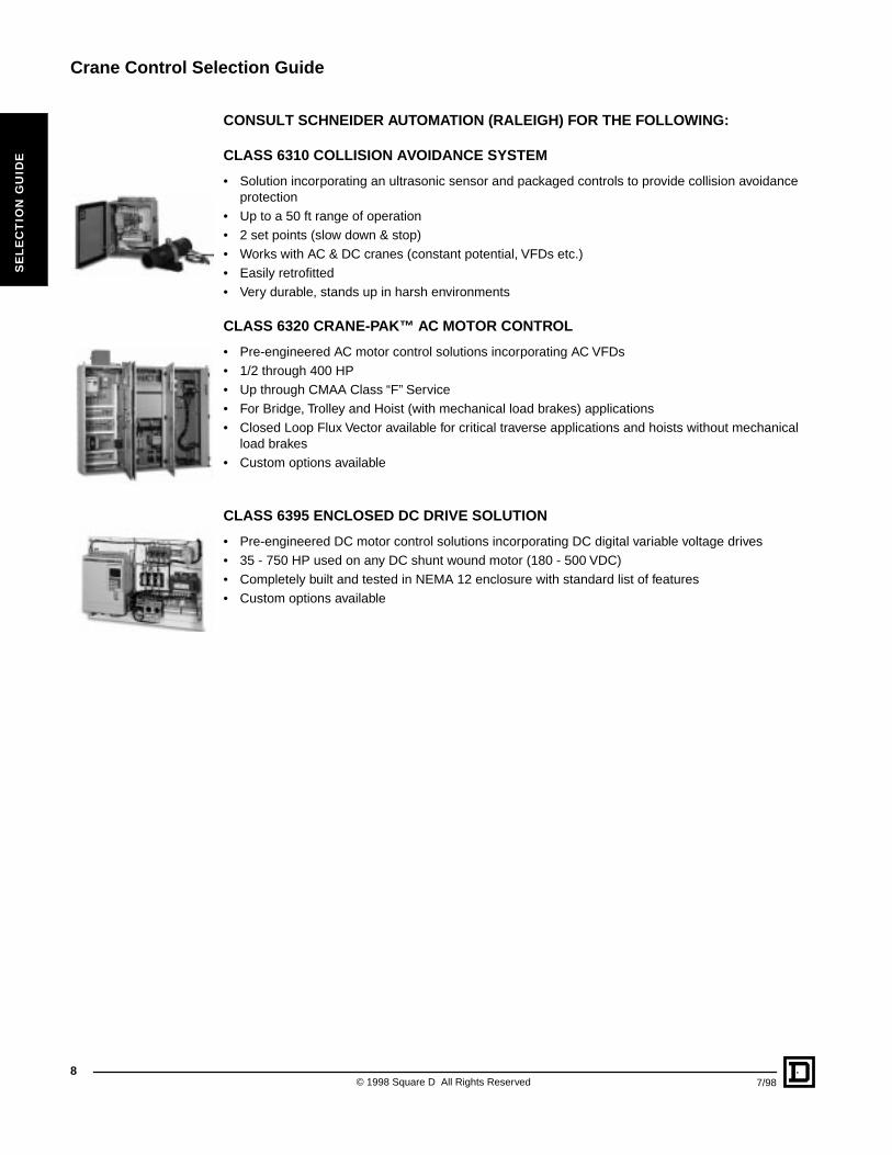
CONSULT SCHNEIDER AUTOMATION (RALEIGH) FOR THE FOLLOWING:
CLASS 6310 COLLISION AVOIDANCE SYSTEM
• Solution incorporating an ultrasonic sensor and packaged controls to provide collision avoidance protection
• Up to a 50 ft range of operation• 2 set points (slow down & stop)• Works with AC & DC cranes (constant potential, VFDs etc.)• Easily retrofitted• Very durable, stands up in harsh environments
CLASS 6320 CRANE-PAK™ AC MOTOR CONTROL
• Pre-engineered AC motor control solutions incorporating AC VFDs• 1/2 through 400 HP• Up through CMAA Class “F” Service• For Bridge, Trolley and Hoist (with mechanical load brakes) applications• Closed Loop Flux Vector available for critical traverse applications and hoists without mechanical
load brakes• Custom options available
CLASS 6395 ENCLOSED DC DRIVE SOLUTION
• Pre-engineered DC motor control solutions incorporating DC digital variable voltage drives• 35 - 750 HP used on any DC shunt wound motor (180 - 500 VDC)• Completely built and tested in NEMA 12 enclosure with standard list of features• Custom options available
© 1998 Square D All Rights Reserved 7/98
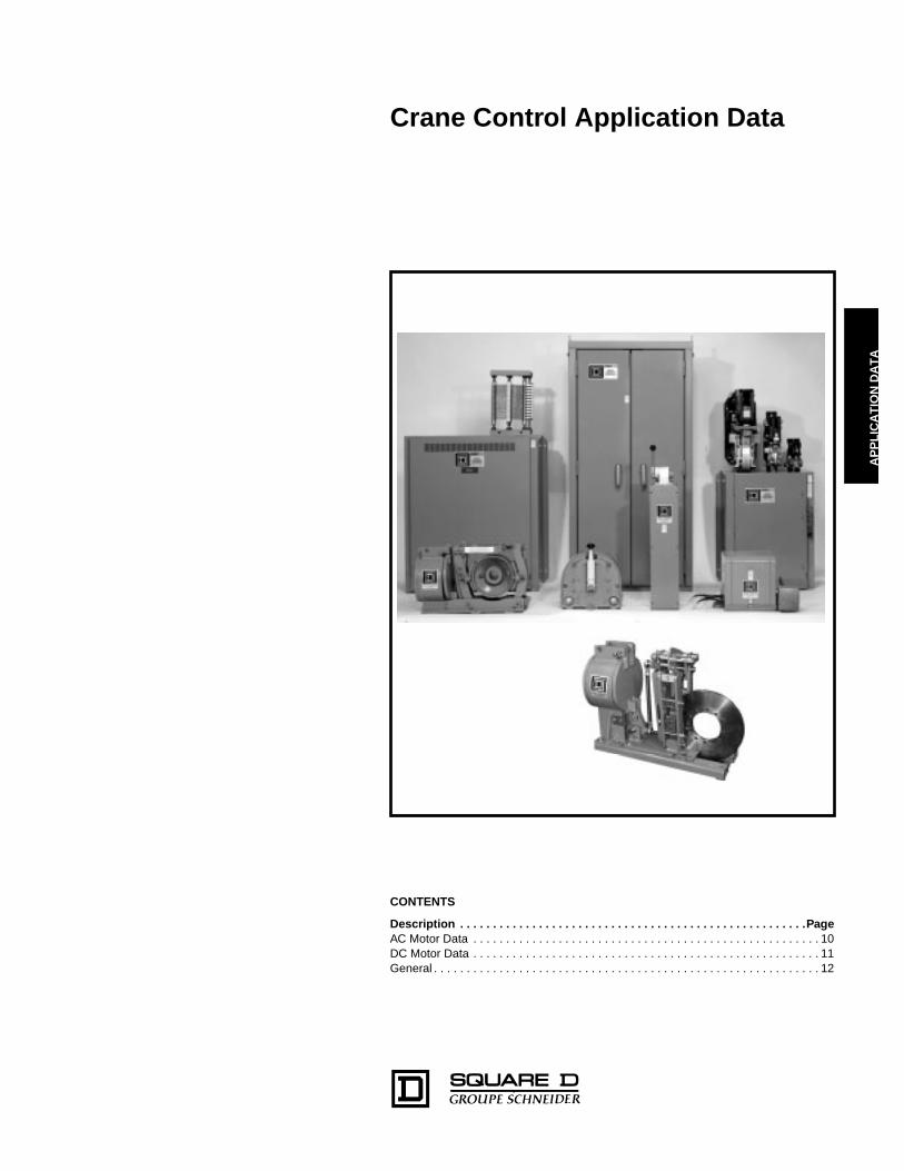
Crane Control Application Data
AP
PL
ICA
TIO
N D
AT
A
CONTENTS
Description . . . . . . . . . . . . . . . . . . . . . . . . . . . . . . . . . . . . . . . . . . . . . . . . . . . . .Page
AC Motor Data . . . . . . . . . . . . . . . . . . . . . . . . . . . . . . . . . . . . . . . . . . . . . . . . . . . . . 10DC Motor Data . . . . . . . . . . . . . . . . . . . . . . . . . . . . . . . . . . . . . . . . . . . . . . . . . . . . . 11General . . . . . . . . . . . . . . . . . . . . . . . . . . . . . . . . . . . . . . . . . . . . . . . . . . . . . . . . . . . 12
Crane Control Application Data
AC Motor Data
© 1998 Square D All Rights Reserved
10
7/98
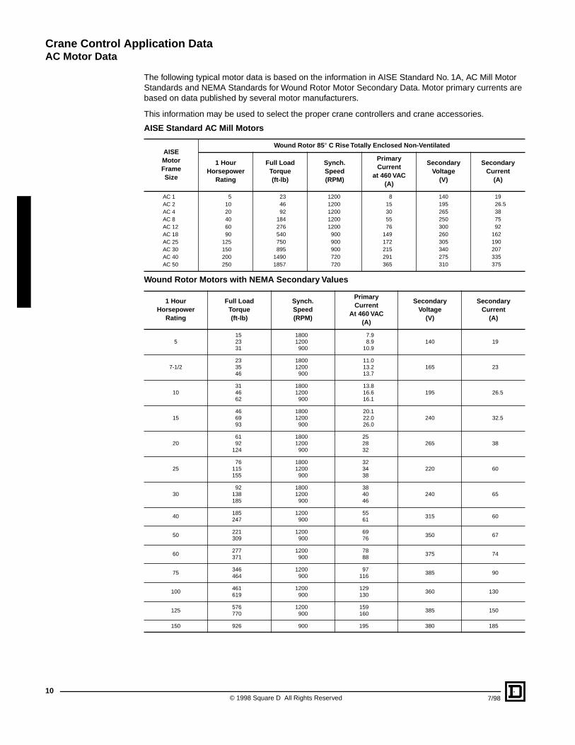
The following typical motor data is based on the information in AISE Standard No. 1A, AC Mill Motor Standards and NEMA Standards for Wound Rotor Motor Secondary Data. Motor primary currents are based on data published by several motor manufacturers.
This information may be used to select the proper crane controllers and crane accessories.
AISE Standard AC Mill Motors
AISEMotorFrameSize
Wound Rotor 85
°
C Rise Totally Enclosed Non-Ventilated
1 HourHorsepower
Rating
Full LoadTorque(ft-lb)
Synch.Speed(RPM)
PrimaryCurrent
at 460 VAC(A)
Secondary Voltage
(V)
SecondaryCurrent
(A)
AC 1AC 2AC 4AC 8AC 12AC 18AC 25AC 30AC 40AC 50
51020406090
125150200250
234692
184276540750895
14901857
12001200120012001200
900900900720720
815305576
149172215291365
140195265250300260305340275310
1926.5387592
162190207335375
Wound Rotor Motors with NEMA Secondary Values
1 HourHorsepower
Rating
Full LoadTorque(ft-lb)
Synch.Speed(RPM)
PrimaryCurrent
At 460 VAC(A)
SecondaryVoltage
(V)
SecondaryCurrent
(A)
5152331
18001200
900
7.98.9
10.9140 19
7-1/2233546
18001200
900
11.013.213.7
165 23
10314662
18001200
900
13.816.616.1
195 26.5
15466993
18001200
900
20.122.026.0
240 32.5
206192
124
18001200
900
252832
265 38
2576
115155
18001200
900
323438
220 60
3092
138185
18001200
900
384046
240 65
40185247
1200900
5561
315 60
50221309
1200900
6976
350 67
60277371
1200900
7888
375 74
75346464
1200900
97116
385 90
100461619
1200900
129130
360 130
125576770
1200900
159160
385 150
150 926 900 195 380 185
Crane Control Application Data
DC Motor Data
11
7/98 © 1998 Square D All Rights Reserved
AP
PL
ICA
TIO
N D
AT
A
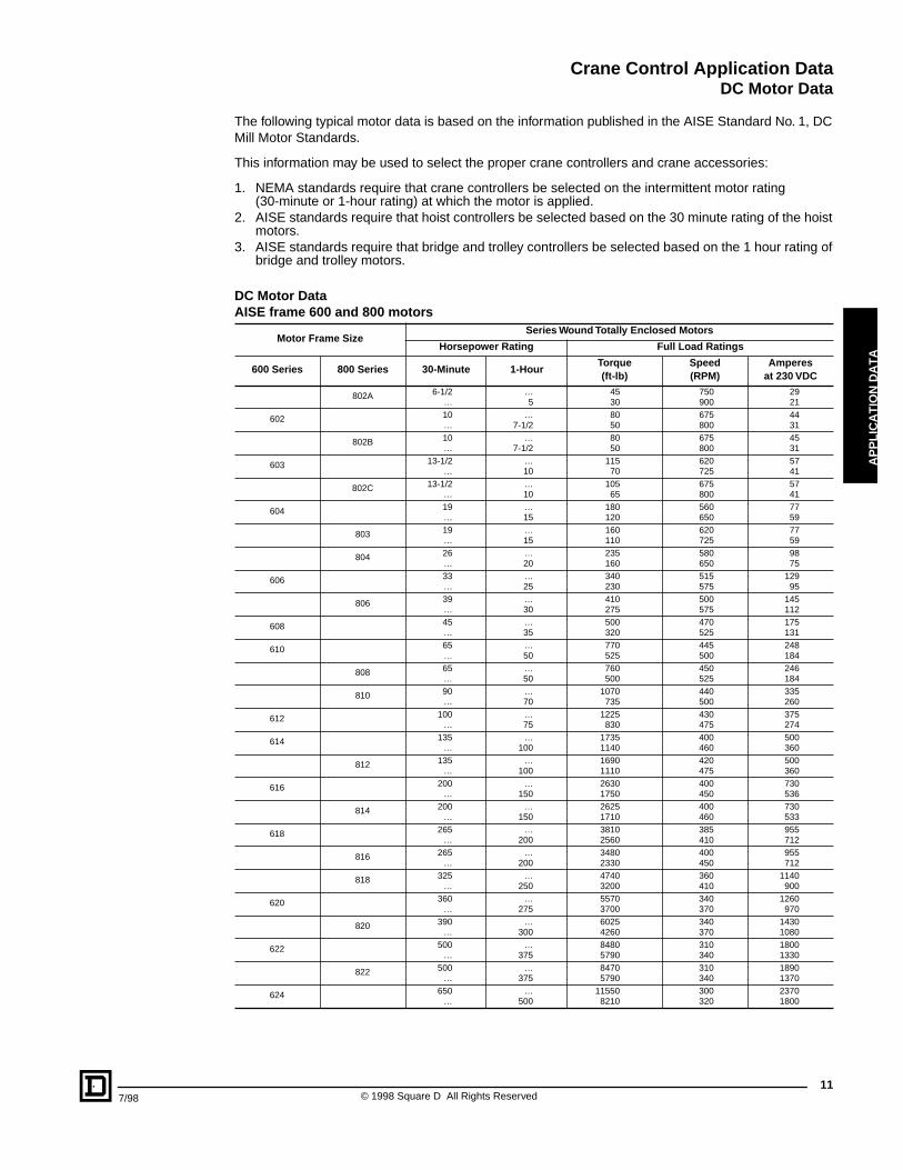
The following typical motor data is based on the information published in the AISE Standard No. 1, DC Mill Motor Standards.
This information may be used to select the proper crane controllers and crane accessories:
1. NEMA standards require that crane controllers be selected on the intermittent motor rating(30-minute or 1-hour rating) at which the motor is applied.
2. AISE standards require that hoist controllers be selected based on the 30 minute rating of the hoist motors.
3. AISE standards require that bridge and trolley controllers be selected based on the 1 hour rating of bridge and trolley motors.
DC Motor DataAISE frame 600 and 800 motors
Motor Frame SizeSeries Wound Totally Enclosed Motors
Horsepower Rating Full Load Ratings
600 Series 800 Series 30-Minute 1-HourTorque(ft-lb)
Speed(RPM)
Amperesat 230 VDC
802A 6-1/2…
…5
4530
750900
2921
602 10…
…7-1/2
8050
675800
4431
802B 10…
…7-1/2
8050
675800
4531
603 13-1/2…
…10
11570
620725
5741
802C 13-1/2…
…10
10565
675800
5741
604 19…
…15
180120
560650
7759
803 19…
…15
160110
620725
7759
804 26…
…20
235160
580650
9875
606 33…
…25
340230
515575
12995
806 39…
…30
410275
500575
145112
608 45…
…35
500320
470525
175131
610 65…
…50
770525
445500
248184
808 65…
…50
760500
450525
246184
810 90…
…70
1070735
440500
335260
612 100…
…75
1225830
430475
375274
614 135…
…100
17351140
400460
500360
812 135…
…100
16901110
420475
500360
616 200…
…150
26301750
400450
730536
814 200…
…150
26251710
400460
730533
618 265…
…200
38102560
385410
955712
816 265…
…200
34802330
400450
955712
818 325…
…250
47403200
360410
1140900
620 360…
…275
55703700
340370
1260970
820 390…
…300
60254260
340370
14301080
622 500…
…375
84805790
310340
18001330
822 500…
…375
84705790
310340
18901370
624 650…
…500
115508210
300320
23701800
Crane Control Application Data
General
© 1998 Square D All Rights Reserved
12
7/98
CLASS A (STANDBY OR INFREQUENT SERVICE)
This service class covers cranes which may be used in installations such as powerhouses, public utilities, turbine rooms, motor rooms and transformer stations where precise handling of equipment at slow speeds with long, idle periods between lifts are required. Capacity loads may be handled for initial installation of equipment and for infrequent maintenance.
CLASS B (LIGHT SERVICE)
This service covers cranes which may be used in repair shops, light assembly operations, service buildings, light warehousing, etc., where service requirements are light and the speed is slow. Loads may vary from no load to occasional full rated loads with two to five lifts per hour, averaging ten feet per lift.
CLASS C (MODERATE SERVICE)
This service covers cranes which may be used in machine shops or papermill machine rooms, etc., where service requirements are moderate. In this type of service the crane will handle loads which average 50 percent of the rated capacity with 5 to 10 lifts per hour, averaging 15 feet, not over 50 percent of the lifts at rated capacity.
CLASS D (HEAVY SERVICE)
This service covers cranes which may be used in heavy machine shops, foundries, fabricating plants, steel warehouses, container yards, lumber mills, etc., and standard duty bucket and magnet operations where heavy duty production is required. In this type of service, loads approaching 50 percent of the rated capacity will be handled constantly during the working period. High speeds are desirable for this type of service with 10 to 20 lifts per hour averaging 15 feet, not over 65 percent of the lifts at rated capacity.
CLASS E (SEVERE)
This type of service requires a crane capable of handling loads approaching a rated capacity throughout its life. Applications may include magnet, bucket, magnet/bucket combination cranes for scrap yards, cement mills, lumber mills, fertilizer plants, container handling, etc., with twenty or more lifts per hour at or near the rated capacity.
CLASS F (CONTINUOUS SEVERE SERVICE)
This type of service requires a crane capable of handling loads approaching rated capacity continuously under severe service conditions throughout its life. Applications may include custom designed specialty cranes essential to performing the critical work tasks affecting the total production facility. These cranes must provide the highest reliability with special attention to ease of maintenance features.
Crane Control Class 5010
CL
AS
S 5
01
0
CONTENTS
Descriptions . . . . . . . . . . . . . . . . . . . . . . . . . . . . . . . . . . . . . . . . . . . . . . . . . . . PageDC Magnetic Drum BrakesGeneral Information . . . . . . . . . . . . . . . . . . . . . . . . . . . . . . . . . . . . . . . . . . . . . . . . .14Pricing and Ordering Information . . . . . . . . . . . . . . . . . . . . . . . . . . . . . . . . . . . . . . .15Application Data and Pricing. . . . . . . . . . . . . . . . . . . . . . . . . . . . . . . . . . . . . . . . . . .19Dimensions and Weights. . . . . . . . . . . . . . . . . . . . . . . . . . . . . . . . . . . . . . . . . . . . . .23
Crane Control Class 5010
DC Magnetic Drum Brakes
14
CL
AS
S 5
01
0
Class 5010Type F132513" Brake
Class 5010Type F300430" Brake
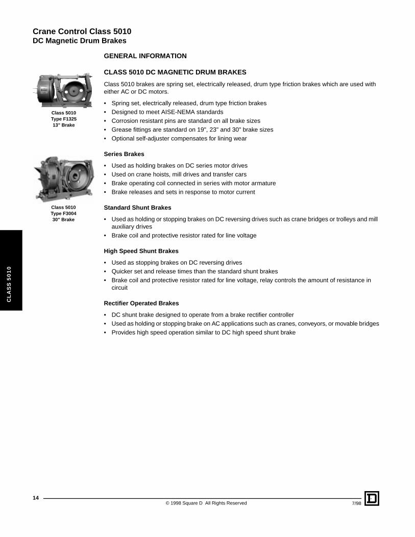
GENERAL INFORMATION
CLASS 5010 DC MAGNETIC DRUM BRAKES
Class 5010 brakes are spring set, electrically released, drum type friction brakes which are used with either AC or DC motors.
• Spring set, electrically released, drum type friction brakes• Designed to meet AISE-NEMA standards• Corrosion resistant pins are standard on all brake sizes• Grease fittings are standard on 19", 23" and 30" brake sizes• Optional self-adjuster compensates for lining wear
Series Brakes
• Used as holding brakes on DC series motor drives• Used on crane hoists, mill drives and transfer cars• Brake operating coil connected in series with motor armature• Brake releases and sets in response to motor current
Standard Shunt Brakes
• Used as holding or stopping brakes on DC reversing drives such as crane bridges or trolleys and mill auxiliary drives
• Brake coil and protective resistor rated for line voltage
High Speed Shunt Brakes
• Used as stopping brakes on DC reversing drives• Quicker set and release times than the standard shunt brakes• Brake coil and protective resistor rated for line voltage, relay controls the amount of resistance in
circuit
Rectifier Operated Brakes
• DC shunt brake designed to operate from a brake rectifier controller• Used as holding or stopping brake on AC applications such as cranes, conveyors, or movable bridges• Provides high speed operation similar to DC high speed shunt brake
© 1998 Square D All Rights Reserved 7/98
Crane Control Class 5010
DC Magnetic Drum Brakes
7/98
CL
AS
S 5
01
0
PRICING AND ORDERING INFORMATION
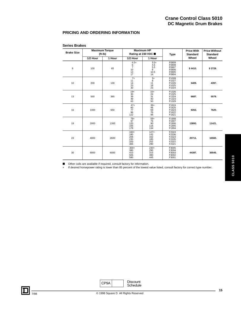
■ Other coils are available if required, consult factory for information.+ If desired horsepower rating is lower than 85 percent of the lowest value listed, consult factory for correct type number.
Series Brakes
Brake SizeMaximum Torque
(ft-lb)Maximum HP
Rating at 230 VDC ■ TypePrice With Standard
Wheel
Price WithoutStandard
Wheel1/2 Hour 1 Hour 1/2 Hour 1 Hour
8 100 65
4.5+67
101317
3.5+4.55.58
10.514
F0809F0808F0807F0806F0805F0804
$ 4410. $ 3728.
10 200 130
7+11142330
5+8
111823
F1028F1027F1026F1025F1024
5409. 4397.
13 550 365
19+30394963
15+24314050
F1326F1325F1324F1323F1329
6687. 5579.
16 1000 650
47+607796
122
36+46597695
F1624F1625F1623F1622F1621
9263. 7620.
19 2000 1300
78+97
120155178
59+7690
116134
F1908F1907F1906F1905F1904
13893. 11421.
23 4000 2600
160+180206235320365
127+142162185252290
F2324F2336F2323F2335F2322F2321
20711. 16560.
30 9000 6000
300+380410505580
230+290315390445
F3005F3004F3003F3002F3001
44397. 36545.
CP9A DiscountSchedule
15© 1998 Square D All Rights Reserved
Crane Control Class 5010
DC Magnetic Drum Brakes
16
CL
AS
S 5
01
0
PRICING AND ORDERING INFORMATION
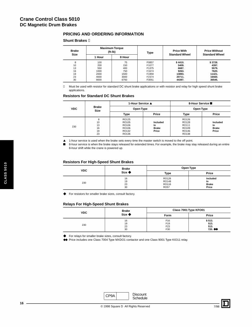
✝ Must be used with resistor for standard DC shunt brake applications or with resistor and relay for high speed shunt brake applications.
▲ 1-hour service is used when the brake sets every time the master switch is moved to the off point.■ 8-hour service is when the brake stays released for extended times. For example, the brake may stay released during an entire
8-hour shift while the crane is powered up.
◆ For resistors for smaller brake sizes, consult factory.
◆ For relays for smaller brake sizes, consult factory.◆◆ Price includes one Class 7004 Type MXDO1 contactor and one Class 9001 Type KIO11 relay.
Shunt Brakes ✝
BrakeSize
Maximum Torque(ft-lb) Type
Price With Standard Wheel
Price Without Standard Wheel
1 Hour 8 Hour
8101316192330
100200550
1000200040009000
75150400750
150030006750
F0857F1077F1375F1674F1959F2374F3051
$ 4410.5409.6687.9263.
13893.20711.44397.
$ 3728.4397.5579.7620.
11421.16560.36545.
Resistors for Standard DC Shunt Brakes
VDCBrakeSize
1-Hour Service ▲ 8-Hour Service ■
Open Type Open Type
Type Price Type Price
230
81013161923
RO125RO105RO106RO106RO132RO136
IncludedInBrakePrice
RO126RO128RO111RO109RO146RO138
IncludedInBrakePrice
Resistors For High-Speed Shunt Brakes
VDCBrakeSize ◆
Open Type
Type Price
230
16192330
RO126RO148RO116RO57
IncludedInBrakePrice
Relays For High-Speed Shunt Brakes
VDCBrakeSize ◆
Class 7001 Type KFO01
Form Price
230
16192330
F16F19F23F30
$ 513.513.513.720. ◆◆
CP9A DiscountSchedule
© 1998 Square D All Rights Reserved 7/98
Crane Control Class 5010
DC Magnetic Drum Brakes
7/98
CL
AS
S 5
01
0
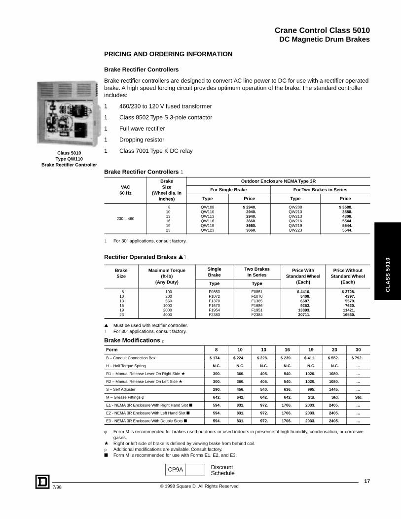
Class 5010Type QW110
Brake Rectifier Controller
PRICING AND ORDERING INFORMATION
Brake Rectifier Controllers
Brake rectifier controllers are designed to convert AC line power to DC for use with a rectifier operated brake. A high speed forcing circuit provides optimum operation of the brake. The standard controller includes:
1 460/230 to 120 V fused transformer
1 Class 8502 Type S 3-pole contactor
1 Full wave rectifier
1 Dropping resistor
1 Class 7001 Type K DC relay
l For 30" applications, consult factory.
▲ Must be used with rectifier controller.l For 30" applications, consult factory.
φ Form M is recommended for brakes used outdoors or used indoors in presence of high humidity, condensation, or corrosive gases.
★ Right or left side of brake is defined by viewing brake from behind coil.p Additional modifications are available. Consult factory.■ Form M is recommended for use with Forms E1, E2, and E3.
Brake Rectifier Controllers l
VAC60 Hz
BrakeSize
(Wheel dia. in inches)
Outdoor Enclosure NEMA Type 3R
For Single Brake For Two Brakes in Series
Type Price Type Price
230 – 460
81013161923
QW108QW110QW113QW116QW119QW123
$ 2940.2940.2940.3660.3660.3660.
QW208QW210QW213QW216QW219QW223
$ 3588.3588.4308.5544.5544.5544.
Rectifier Operated Brakes ▲l
BrakeSize
Maximum Torque(ft-lb)
(Any Duty)
SingleBrake
Two Brakesin Series
Price With Standard Wheel
(Each)
Price Without Standard Wheel
(Each)Type Type
81013161923
100200550
100020004000
F0853F1072F1370F1670F1954F2383
F0851F1070F1385F1686F1951F2384
$ 4410.5409.6687.9263.
13893.20711.
$ 3728.4397.5579.7620.
11421.16560.
Brake Modifications p
Form 8 10 13 16 19 23 30
B – Conduit Connection Box $ 174. $ 224. $ 228. $ 239. $ 411. $ 552. $ 792.
H – Half Torque Spring N.C. N.C. N.C. N.C. N.C. N.C. …
R1 – Manual Release Lever On Right Side ★ 300. 360. 405. 540. 1020. 1080. …
R2 – Manual Release Lever On Left Side ★ 300. 360. 405. 540. 1020. 1080. …
S – Self Adjuster 290. 456. 540. 636. 995. 1445. …
M – Grease Fittings φ 642. 642. 642. 642. Std. Std. Std.
E1 - NEMA 3R Enclosure With Right Hand Slot ■ 594. 831. 972. 1706. 2033. 2405. …
E2 - NEMA 3R Enclosure With Left Hand Slot ■ 594. 831. 972. 1706. 2033. 2405. …
E3 - NEMA 3R Enclosure With Double Slots ■ 594. 831. 972. 1706. 2033. 2405. …
CP9A DiscountSchedule
17© 1998 Square D All Rights Reserved
Crane Control Class 5010
DC Magnetic Drum Brakes
18
CL
AS
S 5
01
0
ORDERING INFORMATION
Ordering Information Required:
1. For DC magnetic brake:
a. Classb. Typec. With or without wheeld. Modifications: specify form letterse. Torque setting if different from maximumf. Voltage if different from standard
2. For DC brake when Class and Type cannot be specified:
a. Series, shunt, or rectifier operatedb. Motor HP & voltagec. Motor application (hoist, bridge, trolley, etc.)d. Modificationse. With or without wheel
3. For resistor for standard shunt brake (if required) orFor resistor or relay for high speed shunt brake (if required):
a. Classb. Type
4. For brake rectifier controller (if required):
a. Classb. Type c. Voltage and frequency (specify V80 for 230 VAC, or V81 for 460 VAC)d. Brake size
5. For brake wheel purchased with brake:Supply the dimensions required for ordering wheels.
6. For brake wheels only:When purchased separately, the brake wheel is considered to be a replacement part. Furnish the original Square D brake wheel part number or the dimensions required for ordering wheels.
© 1998 Square D All Rights Reserved 7/98
Crane Control Class 5010
DC Magnetic Drum Brakes
7/98
CL
AS
S 5
01
0
EF
C G
O
BHD
C
OF BRAKEL
YX
APPLICATION DATA AND PRICING INFORMATION
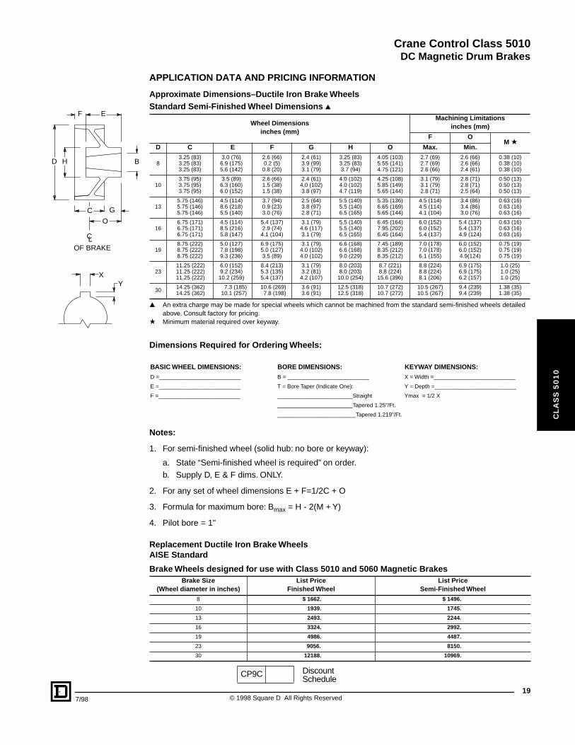
Approximate Dimensions–Ductile Iron Brake Wheels
▲ An extra charge may be made for special wheels which cannot be machined from the standard semi-finished wheels detailed above. Consult factory for pricing.
★ Minimum material required over keyway.
Notes:
1. For semi-finished wheel (solid hub: no bore or keyway):
a. State “Semi-finished wheel is required” on order.b. Supply D, E & F dims. ONLY.
2. For any set of wheel dimensions E + F=1/2C + O
3. Formula for maximum bore: Bmax = H - 2(M + Y)
4. Pilot bore = 1"
Replacement Ductile Iron Brake Wheels AISE Standard
Standard Semi-Finished Wheel Dimensions ▲
Wheel Dimensionsinches (mm)
Machining Limitationsinches (mm)
F OM ★
D C E F G H O Max. Min.
83.25 (83)3.25 (83)3.25 (83)
3.0 (76)6.9 (175)5.6 (142)
2.6 (66)0.2 (5)0.8 (20)
2.4 (61)3.9 (99)3.1 (79)
3.25 (83)3.25 (83)3.7 (94)
4.05 (103)5.55 (141)4.75 (121)
2.7 (69)2.7 (69)2.6 (66)
2.6 (66)2.6 (66)2.4 (61)
0.38 (10)0.38 (10)0.38 (10)
103.75 (95)3.75 (95)3.75 (95)
3.5 (89)6.3 (160)6.0 (152)
2.6 (66)1.5 (38)1.5 (38)
2.4 (61)4.0 (102)3.8 (97)
4.0 (102)4.0 (102)4.7 (119)
4.25 (108)5.85 (149)5.65 (144)
3.1 (79)3.1 (79)2.8 (71)
2.8 (71)2.8 (71)2.5 (64)
0.50 (13)0.50 (13)0.50 (13)
135.75 (146)5.75 (146)5.75 (146)
4.5 (114)8.6 (218)5.5 (140)
3.7 (94)0.9 (23)3.0 (76)
2.5 (64)3.8 (97)2.8 (71)
5.5 (140)5.5 (140)6.5 (165)
5.35 (136)6.65 (169)5.65 (144)
4.5 (114)4.5 (114)4.1 (104)
3.4 (86)3.4 (86)3.0 (76)
0.63 (16)0.63 (16)0.63 (16)
166.75 (171)6.75 (171)6.75 (171)
4.5 (114)8.5 (216)5.8 (147)
5.4 (137)2.9 (74)4.1 (104)
3.1 (79)4.6 (117)3.1 (79)
5.5 (140)5.5 (140)6.5 (165)
6.45 (164)7.95 (202)6.45 (164)
6.0 (152)6.0 (152)5.4 (137)
5.4 (137)5.4 (137)4.9 (124)
0.63 (16)0.63 (16)0.63 (16)
198.75 (222)8.75 (222)8.75 (222)
5.0 (127)7.8 (198)9.3 (236)
6.9 (175)5.0 (127)3.5 (89)
3.1 (79)4.0 (102)4.0 (102)
6.6 (168)6.6 (168)9.0 (229)
7.45 (189)8.35 (212)8.35 (212)
7.0 (178)7.0 (178)6.1 (155)
6.0 (152)6.0 (152)4.9(124)
0.75 (19)0.75 (19)0.75 (19)
2311.25 (222)11.25 (222)11.25 (222)
6.0 (152)9.2 (234)10.2 (259)
8.4 (213)5.3 (135)5.4 (137)
3.1 (79)3.2 (81)4.2 (107)
8.0 (203)8.0 (203)10.0 (254)
8.7 (221)8.8 (224)15.6 (396)
8.8 (224)8.8 (224)8.1 (206)
6.9 (175)6.9 (175)6.2 (157)
1.0 (25)1.0 (25)1.0 (25)
30 14.25 (362)14.25 (362)
7.3 (185)10.1 (257)
10.6 (269)7.8 (198)
3.6 (91)3.6 (91)
12.5 (318)12.5 (318)
10.7 (272)10.7 (272)
10.5 (267)10.5 (267)
9.4 (239)9.4 (239)
1.38 (35)1.38 (35)
Dimensions Required for Ordering Wheels:
BASIC WHEEL DIMENSIONS: BORE DIMENSIONS: KEYWAY DIMENSIONS:D =__________________________ B = __________________________ X = Width =__________________________
E =__________________________ T = Bore Taper (Indicate One): Y = Depth =__________________________
F =__________________________ ________________________Straight Ymax = 1/2 X
________________________Tapered 1.25"/Ft.
_________________________Tapered 1.219"/Ft.
Brake Wheels designed for use with Class 5010 and 5060 Magnetic BrakesBrake Size
(Wheel diameter in inches)List Price
Finished WheelList Price
Semi-Finished Wheel8 $ 1662. $ 1496.
10 1939. 1745.
13 2493. 2244.
16 3324. 2992.
19 4986. 4487.
23 9056. 8150.
30 12188. 10969.
CP9C DiscountSchedule
19© 1998 Square D All Rights Reserved
Crane Control Class 5010
Application Data
20
CL
AS
S 5
01
0
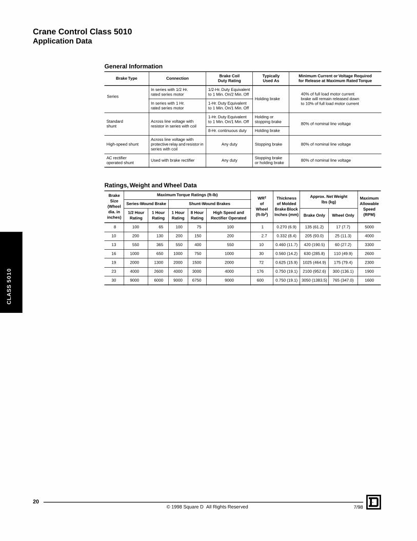
General Information
Brake Type Connection Brake CoilDuty Rating
TypicallyUsed As
Minimum Current or Voltage Requiredfor Release at Maximum Rated Torque
Series
In series with 1/2 Hr.rated series motor
1/2-Hr. Duty Equivalentto 1 Min. On/2 Min. Off
Holding brake40% of full load motor current brake will remain released down to 10% of full load motor currentIn series with 1 Hr.
rated series motor1-Hr. Duty Equivalentto 1 Min. On/1 Min. Off
Standard shunt
Across line voltage with resistor in series with coil
1-Hr. Duty Equivalentto 1 Min. On/1 Min. Off
Holding or stopping brake 80% of nominal line voltage
8-Hr. continuous duty Holding brake
High-speed shuntAcross line voltage with protective relay and resistor in series with coil
Any duty Stopping brake 80% of nominal line voltage
AC rectifier operated shunt
Used with brake rectifier Any dutyStopping brakeor holding brake
80% of nominal line voltage
Ratings, Weight and Wheel Data
Brake Size
(Wheel dia. in
inches)
Maximum Torque Ratings (ft-lb)WR2
ofWheel(ft-lb2)
Thickness of Molded
Brake Block Inches (mm)
Approx. Net Weightlbs (kg)
Maximum Allowable
Speed(RPM)
Series-Wound Brake Shunt-Wound Brakes
1/2 HourRating
1 HourRating
1 HourRating
8 HourRating
High Speed and Rectifier Operated
Brake Only Wheel Only
8 100 65 100 75 100 1 0.270 (6.9) 135 (61.2) 17 (7.7) 5000
10 200 130 200 150 200 2.7 0.332 (8.4) 205 (93.0) 25 (11.3) 4000
13 550 365 550 400 550 10 0.460 (11.7) 420 (190.5) 60 (27.2) 3300
16 1000 650 1000 750 1000 30 0.560 (14.2) 630 (285.8) 110 (49.9) 2600
19 2000 1300 2000 1500 2000 72 0.625 (15.9) 1025 (464.9) 175 (79.4) 2300
23 4000 2600 4000 3000 4000 176 0.750 (19.1) 2100 (952.6) 300 (136.1) 1900
30 9000 6000 9000 6750 9000 600 0.750 (19.1) 3050 (1383.5) 765 (347.0) 1600
© 1998 Square D All Rights Reserved 7/98
Crane Control Class 5010
Application Data
7/98
CL
AS
S 5
01
0
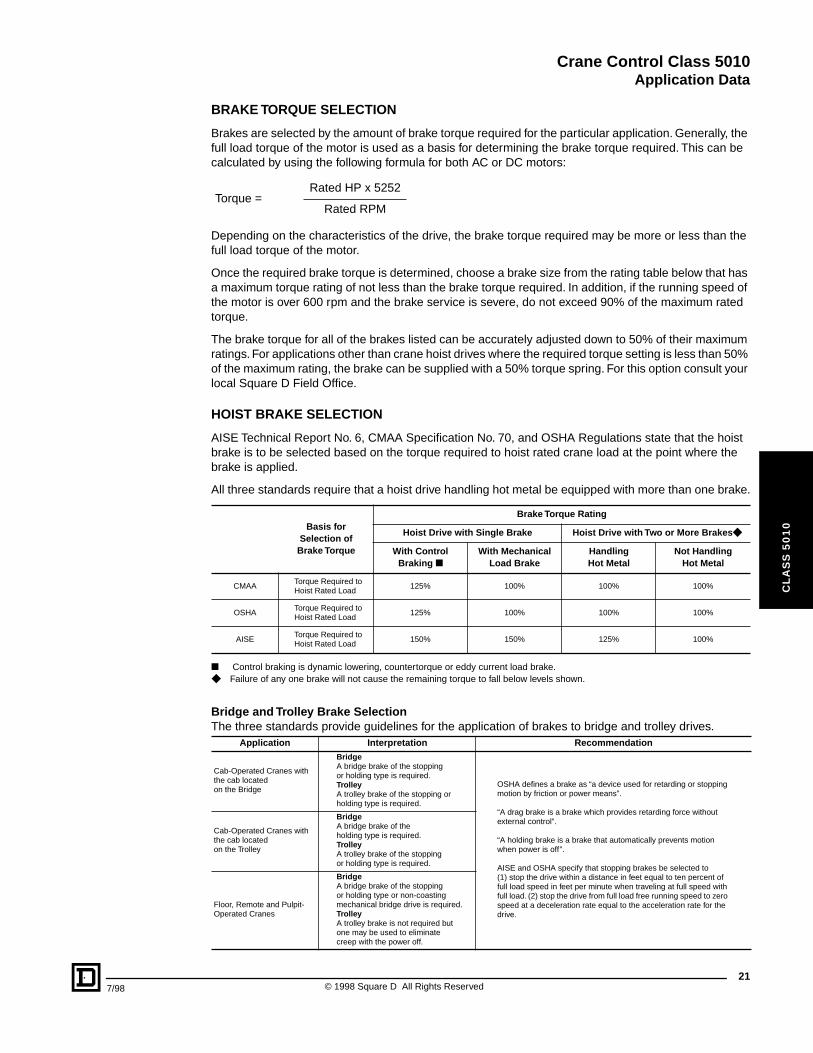
BRAKE TORQUE SELECTION
Brakes are selected by the amount of brake torque required for the particular application. Generally, the full load torque of the motor is used as a basis for determining the brake torque required. This can be calculated by using the following formula for both AC or DC motors:
Depending on the characteristics of the drive, the brake torque required may be more or less than the full load torque of the motor.
Once the required brake torque is determined, choose a brake size from the rating table below that has a maximum torque rating of not less than the brake torque required. In addition, if the running speed of the motor is over 600 rpm and the brake service is severe, do not exceed 90% of the maximum rated torque.
The brake torque for all of the brakes listed can be accurately adjusted down to 50% of their maximum ratings. For applications other than crane hoist drives where the required torque setting is less than 50% of the maximum rating, the brake can be supplied with a 50% torque spring. For this option consult your local Square D Field Office.
HOIST BRAKE SELECTION
AISE Technical Report No. 6, CMAA Specification No. 70, and OSHA Regulations state that the hoist brake is to be selected based on the torque required to hoist rated crane load at the point where the brake is applied.
All three standards require that a hoist drive handling hot metal be equipped with more than one brake.
■ Control braking is dynamic lowering, countertorque or eddy current load brake.◆ Failure of any one brake will not cause the remaining torque to fall below levels shown.
Torque =Rated HP x 5252
Rated RPM
Basis forSelection of
Brake Torque
Brake Torque Rating
Hoist Drive with Single Brake Hoist Drive with Two or More Brakes◆
With ControlBraking ■
With MechanicalLoad Brake
HandlingHot Metal
Not Handling Hot Metal
CMAATorque Required to Hoist Rated Load
125% 100% 100% 100%
OSHATorque Required to Hoist Rated Load
125% 100% 100% 100%
AISETorque Required to Hoist Rated Load
150% 150% 125% 100%
Bridge and Trolley Brake SelectionThe three standards provide guidelines for the application of brakes to bridge and trolley drives.
Application Interpretation Recommendation
Cab-Operated Cranes with the cab locatedon the Bridge
BridgeA bridge brake of the stopping or holding type is required.TrolleyA trolley brake of the stopping or holding type is required.
OSHA defines a brake as “a device used for retarding or stopping motion by friction or power means”.
“A drag brake is a brake which provides retarding force without external control”.
“A holding brake is a brake that automatically prevents motion when power is off”.
AISE and OSHA specify that stopping brakes be selected to (1) stop the drive within a distance in feet equal to ten percent of full load speed in feet per minute when traveling at full speed with full load. (2) stop the drive from full load free running speed to zero speed at a deceleration rate equal to the acceleration rate for the drive.
Cab-Operated Cranes with the cab located on the Trolley
BridgeA bridge brake of the holding type is required.TrolleyA trolley brake of the stopping or holding type is required.
Floor, Remote and Pulpit-Operated Cranes
BridgeA bridge brake of the stopping or holding type or non-coasting mechanical bridge drive is required.TrolleyA trolley brake is not required but one may be used to eliminatecreep with the power off.
21© 1998 Square D All Rights Reserved
Crane Control Class 5010
Application Data
22
CL
AS
S 5
01
0
© 1998 Square D All Rights Reserved 7/98
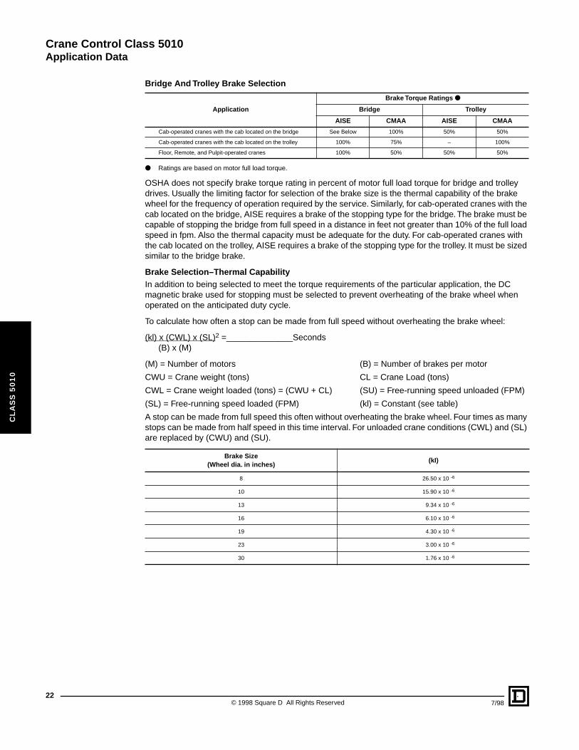
● Ratings are based on motor full load torque.
OSHA does not specify brake torque rating in percent of motor full load torque for bridge and trolley drives. Usually the limiting factor for selection of the brake size is the thermal capability of the brake wheel for the frequency of operation required by the service. Similarly, for cab-operated cranes with the cab located on the bridge, AISE requires a brake of the stopping type for the bridge. The brake must be capable of stopping the bridge from full speed in a distance in feet not greater than 10% of the full load speed in fpm. Also the thermal capacity must be adequate for the duty. For cab-operated cranes with the cab located on the trolley, AISE requires a brake of the stopping type for the trolley. It must be sized similar to the bridge brake.
Brake Selection–Thermal CapabilityIn addition to being selected to meet the torque requirements of the particular application, the DC magnetic brake used for stopping must be selected to prevent overheating of the brake wheel when operated on the anticipated duty cycle.
To calculate how often a stop can be made from full speed without overheating the brake wheel:
(kl) x (CWL) x (SL)2 =______________Seconds(B) x (M)
(M) = Number of motors (B) = Number of brakes per motor
CWU = Crane weight (tons) CL = Crane Load (tons)
CWL = Crane weight loaded (tons) = (CWU + CL) (SU) = Free-running speed unloaded (FPM)
(SL) = Free-running speed loaded (FPM) (kl) = Constant (see table)
A stop can be made from full speed this often without overheating the brake wheel. Four times as many stops can be made from half speed in this time interval. For unloaded crane conditions (CWL) and (SL) are replaced by (CWU) and (SU).
Bridge And Trolley Brake Selection
Application
Brake Torque Ratings ●
Bridge Trolley
AISE CMAA AISE CMAA
Cab-operated cranes with the cab located on the bridge See Below 100% 50% 50%
Cab-operated cranes with the cab located on the trolley 100% 75% – 100%
Floor, Remote, and Pulpit-operated cranes 100% 50% 50% 50%
Brake Size(Wheel dia. in inches)
(kI)
8 26.50 x 10 -6
10 15.90 x 10 -6
13 9.34 x 10 -6
16 6.10 x 10 -6
19 4.30 x 10 -6
23 3.00 x 10 -6
30 1.76 x 10 -6
Crane Control Class 5010
Approximate Dimensions and Weights
7/98
CL
AS
S 5
01
0
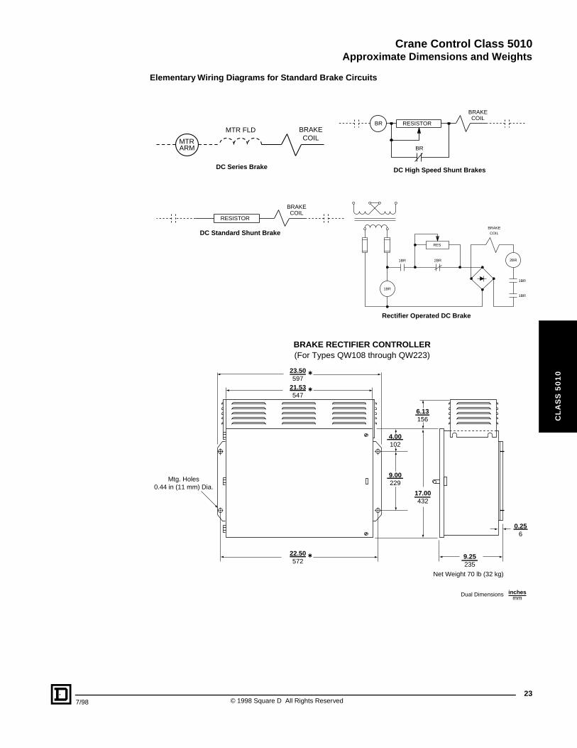
Elementary Wiring Diagrams for Standard Brake Circuits
MTRARM
MTR FLD BRAKECOIL
BRAKECOIL
RESISTOR
BRAKE
BR
BR
COILRESISTOR
RES
2BR
1BR
1BR 2BR
1BR
1BR
COILBRAKE
DC High Speed Shunt BrakesDC Series Brake
DC Standard Shunt Brake
Rectifier Operated DC Brake
9.25 235
0.25 6
23.50 597
21.53 547
22.50 572
Mtg. Holes0.44 in (11 mm) Dia.
4.00 102
6.13 156
9.00 229
17.00 432
Net Weight 70 lb (32 kg)
BRAKE RECTIFIER CONTROLLER(For Types QW108 through QW223)
t
t
t
Dual Dimensions inchesmm
23© 1998 Square D All Rights Reserved
Crane Control Class 5010
Approximate Dimensions
24
CL
AS
S 5
01
0
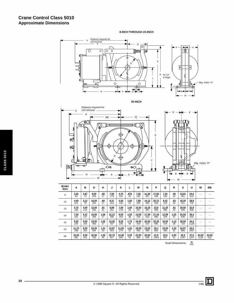
Brake Size A B D H J K L M N P Q R S U W BB
8 3.2583
2.8773
8.00204
.6917
7.00178
4.75121
.87522
7.56192
11.30287
17.65448
7.25184
.5614
13.81351
24.0610
… …
10 4.00101
3.1279
10.00254
.6917
8.37213
5.50140
1.0025
7.88200
14.12359
20.72526
8.42219
.6316
16.20411
28.8732
… …
13 5.75146
4.50114
13.00330
.8121
9.88251
7.00178
1.0025
10.50267
15.25387
23.6599
11.25286
.9123
20.00508
32.9836
… …
16 7.50191
5.37137
16.00406
1.0627
12.12308
8.00203
1.5038
13.00330
17.06433
27.16690
12.96329
1.2532
25.50648
36.4925
… …
19 9.25235
6.50165
19.00483
1.0627
13.25337
9.25235
1.7544
16.50419
20.06510
33.25845
16.50419
1.1228
28.50724
44.41128
… …
23 11.75298
8.00203
23.00584
1.3133
15.87403
11.00279
1.2532
19.00483
19.25489
35.1892
19.50495
1.2532
34.87886
42.01067
… …
30 15.00381
9.50241
30.00762
1.5640
20.75527
13.38340
2.0051
23.00584
25.00635
41.91064
23.5597
2.0051
42.51207
47.51207
44.631134
24.50622
Dual Dimensions: inmm
Mtg. Holes "H"
R
B B
M
S
J
S
for 13"& larger
K K
Q
D
U
P
Distance required forcoil removal
N A AL
L
WN A A
U
PBB Q
Distance required forcoil removal
LL
J
S
K K
R
B B
M
Mtg. Holes "H"
D
8-INCH THROUGH 23-INCH
30-INCH
© 1998 Square D All Rights Reserved 7/98
Crane Control Class 5015
CL
AS
S 5
01
5
CONTENTS
Description . . . . . . . . . . . . . . . . . . . . . . . . . . . . . . . . . . . . . . . . . . . . . . . . . . . . Page
General Information . . . . . . . . . . . . . . . . . . . . . . . . . . . . . . . . . . . . . . . . . . . . . . . . .26Pricing and Ordering Information . . . . . . . . . . . . . . . . . . . . . . . . . . . . . . . . . . . . . . .27Application Data and Pricing. . . . . . . . . . . . . . . . . . . . . . . . . . . . . . . . . . . . . . . . . . .31Dimensions . . . . . . . . . . . . . . . . . . . . . . . . . . . . . . . . . . . . . . . . . . . . . . . . . . . . . . . .33
Crane Control Class 5015
DC Magnetic Caliper Disc Brakes
26
CL
AS
S 5
01
5
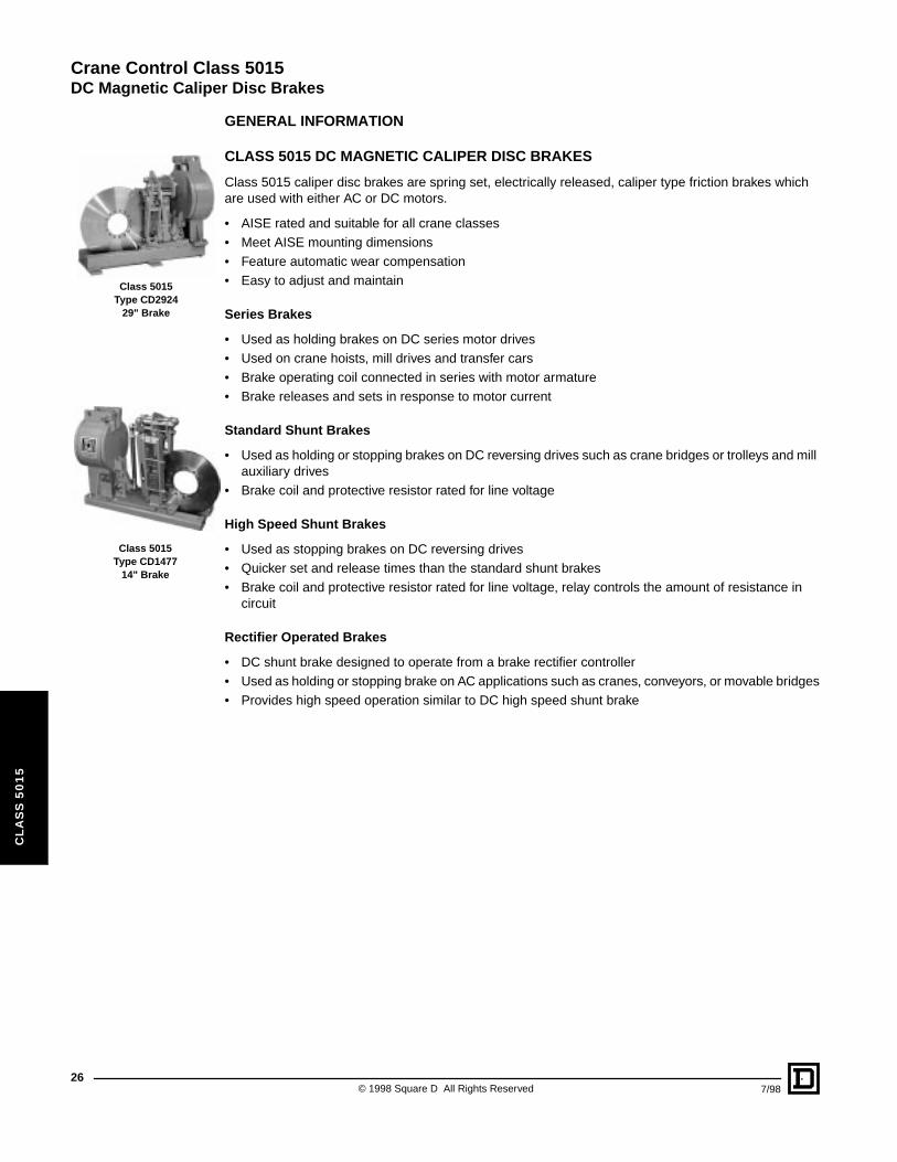
Class 5015Type CD2924
29" Brake
Class 5015Type CD1477
14" Brake
GENERAL INFORMATION
CLASS 5015 DC MAGNETIC CALIPER DISC BRAKES
Class 5015 caliper disc brakes are spring set, electrically released, caliper type friction brakes which are used with either AC or DC motors.
• AISE rated and suitable for all crane classes• Meet AISE mounting dimensions• Feature automatic wear compensation• Easy to adjust and maintain
Series Brakes
• Used as holding brakes on DC series motor drives• Used on crane hoists, mill drives and transfer cars• Brake operating coil connected in series with motor armature• Brake releases and sets in response to motor current
Standard Shunt Brakes
• Used as holding or stopping brakes on DC reversing drives such as crane bridges or trolleys and mill auxiliary drives
• Brake coil and protective resistor rated for line voltage
High Speed Shunt Brakes
• Used as stopping brakes on DC reversing drives• Quicker set and release times than the standard shunt brakes• Brake coil and protective resistor rated for line voltage, relay controls the amount of resistance in
circuit
Rectifier Operated Brakes
• DC shunt brake designed to operate from a brake rectifier controller• Used as holding or stopping brake on AC applications such as cranes, conveyors, or movable bridges• Provides high speed operation similar to DC high speed shunt brake
© 1998 Square D All Rights Reserved 7/98
Crane Control Class 5015
DC Magnetic Caliper Disc Brakes
7/98
CL
AS
S 5
01
5
PRICING AND ORDERING INFORMATION
■ Other coils are available if required, consult factory for information.+ If desired horsepower rating is lower than 85 percent of the lowest value listed, consult factory for correct type number.
Series BrakesBrake Size(Disc Dia.in inches)
Maximum Torque(ft-lb)
Maximum HPRating at 230 VDC ■ Type
Price With Hub and Disc
Price WithoutHub and Disc
1/2 Hour 1 Hour 1/2 Hour 1 Hour
14 200 130
7+11142330
5+8
111823
CD1428CD1427CD1426CD1425CD1424
$7302. $5936.
17 550 365
19+30394963
15+24314050
CD1726CD1725CD1724CD1723CD1729
9027. 7532.
21 1000 650
47+607796
122
36+46597695
CD2124CD2125CD2123CD2122CD2121
12505. 10287.
24 2000 1300
78+97
120155178
59+7690
116134
CD2408CD2407CD2406CD2405CD2404
18756. 15418.
29 4000 2600
160+180206235320365
127+142162185252290
CD2924CD2936CD2923CD2935CD2922CD2921
27960. 22356.
CP9A DiscountSchedule
27© 1998 Square D All Rights Reserved
Crane Control Class 5015
DC Magnetic Caliper Disc Brakes
28
CL
AS
S 5
01
5
PRICING AND ORDERING INFORMATION
✝ Must be used with resistor for standard DC shunt brake applications or with resistor and relay for high speed shunt brake applications.
▲ 1-hour service is used when the brake sets every time the master switch is moved to the off point.■ 8-hour service is when the brake stays released for extended times. For example, the brake may stay released during an entire
8-hour shift while the crane is powered up.
◆ For smaller brake sizes, consult factory.
Shunt Brakes ✝
BrakeSize
(Disc Dia.in inches)
Maximum Torque(ft-lb)
TypePrice With
Hub and DiscPrice Without Hub and Disc
1 Hour 8 Hour
1417212429
200550
100020004000
150400750
15003000
CD1477CD1775CD2174CD2459CD2974
$ 7302.9027.
12505.18756.27960.
$5936.7532.
10287.15418.22356.
Resistors for Standard DC Shunt Brakes
VDC
BrakeSize
(Disc dia.in inches)
1-Hour Service ▲ 8-Hour Service ■
Open Type Open Type
Type Price Type Price
230
1417212429
RO105RO106RO106RO132RO136
IncludedInBrakePrice
RO128RO111RO109RO146RO138
IncludedInBrakePrice
Resistors For High-Speed Shunt Brakes
VDC
BrakeSize ◆
(Disc dia.in inches)
Open Type
Type Price
230212429
RO126RO148RO116
IncludedInBrakePrice
Relays For High-Speed Shunt Brakes
VDC
BrakeSize ◆
(Disc dia.in inches)
Class 7001 Type KFO-01
Form Price
230212429
F16F19F23
$ 513.513.513.
CP9A DiscountSchedule
© 1998 Square D All Rights Reserved 7/98
Crane Control Class 5015
DC Magnetic Caliper Disc Brakes
7/98
CL
AS
S 5
01
5
Class 5010Type QW110
Brake Rectifier Controller
PRICING AND ORDERING INFORMATION
Brake Rectifier Controllers
Brake rectifier controllers are designed to convert AC line power to DC for use with a rectifier operated brake. A high speed forcing circuit provides optimum operation of the brake. The standard controller includes:
1 460/230 to 120 V fused transformer
1 Class 8502 Type S 3-pole contactor
1 Full wave rectifier
1 Dropping resistor
1 Class 7001 Type K DC relay
l Class 5010
▲ Must be used with rectifier controller.
◆ Consult factory for additional modifications.
Brake Rectifier Controllers l
VAC60 Hz
BrakeSize
(Disc dia.in inches)
Outdoor Enclosure NEMA Type 3R
For Single Brake For Two Brakes in Series
Type Price Type Price
230 – 460
1417212429
QW110QW113QW116QW119QW123
$ 2940.2940.3660.3660.3660.
QW210QW213QW216QW219QW223
$ 3588.4308.5544.5544.5544.
Rectifier Operated Brakes ▲
BrakeSize
(Disc Dia.in Inches)
Maximum Torque(ft-lb)
(Any Duty)
SingleBrake
Two Brakesin Series
Price With Hub and Disc
(Each)
Price WithoutHub and Disc
(Each)Type Type
1417212429
200550
100020004000
CD1472CD1770CD2170CD2454CD2983
CD1470CD1785CD2186CD2451CD2984
$ 7302.9027.
12505.18756.27960.
$ 5936.7532.
10287.15418.22356.
Brake Modifications ◆
Form 14 17 21 24 29
B – Conduit Connection Box $ 224. $ 224. $ 239. $ 411. $ 552.
R – Manual Release Lever 405. 405. 540. 1020. 1080.
NEMA 3R Enclosure 456. 540. 636. 995. 1445.
CP9A DiscountSchedule
29© 1998 Square D All Rights Reserved
Crane Control Class 5015
DC Magnetic Caliper Disc Brakes
30
CL
AS
S 5
01
5
ORDERING INFORMATION
Ordering Information Required:
1. For DC magnetic brake:
a. Classb. Typec. With or without hub and discd. Modifications: specify Formse. Torque setting if different from maximumf. Voltage if different from standard
2. For DC brake when Class and Type cannot be specified:
a. Series, shunt, or rectifier operatedb. Motor HP & voltagec. Motor application (hoist, bridge, trolley, etc.)d. Modificationse. With or without hub and disc
3. For resistor for standard shunt brake (if required) orFor resistor or relay for high speed shunt brake (if required):
a. Classb. Type
4. For brake rectifier controller (if required):
a. Classb. Type c. Voltage and frequencyd. Brake size
5. For brake hub and disc purchased with brake:Supply the dimensions required for ordering hub and disc as listed on page 31.
6. For disc only:When purchased separately, the disc is considered to be a replacement part. Furnish the original Square D part number or the dimensions required for ordering as listed on page 31.
© 1998 Square D All Rights Reserved 7/98
Crane Control Class 5015
DC Magnetic Caliper Disc Brakes
CL
AS
S 5
01
5
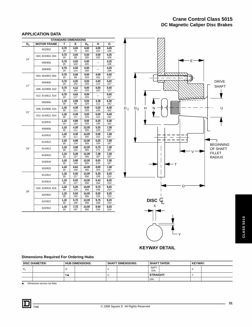
APPLICATION DATA
▲ Dimension across nut flats.
STANDARD DIMENSIONSD1 MOTOR FRAME T E D3 H O
14"
602/8020.7920
3.0076
6.50165
4.00102
4.25108
603, 604/803, 8040.7920
3.5089
6.50165
4.00102
4.25108
606/8060.7920
4.00102
6.50165
– 4.25108
608/8080.7920
4.50114
6.50165
– 4.25108
17"
603, 604/803, 8040.7920
3.5089
9.00229
4.00102
5.00127
606/8060.7920
4.00102
9.00229
4.50114
5.00127
608, 610/808, 8100.7920
4.12105
9.00229
6.00152
5.00127
612, 614/812, 8140.7920
4.62117
9.00229
– 5.00127
21"
606/8061.1830
3.8899
9.00229
4.38111
6.38162
608, 610/808, 8101.1830
4.38111
9.00229
5.25133
6.38162
612, 614/812, 8141.1830
4.38111
9.00229
6.00152
6.38162
616/8161.1830
4.88124
9.00229
6.25159
6.38162
24"
608/8081.1830
4.38111
12.00305
5.25133
7.38187
610/8101.1830
4.38111
12.00305
6.00152
7.38187
612/8121.1830
4.88124
12.00305
6.25159
7.38187
614/8141.1830
4.88124
12.00305
6.75171
7.38187
616/8161.1830
5.38137
12.00305
7.38187
7.38187
618/8181.1830
5.88149
12.00305
8.25210
7.38187
620/8201.1830
6.62168
12.00305
8.00203
7.38187
29"
612/8121.1830
5.00127
14.00356
6.25159
8.25210
614/8141.1830
5.00127
14.00356
6.44164
8.25210
616, 618/816, 8181.1830
5.25133
14.00356
9.75248
8.25210
620/8201.1830
5.50140
14.00356
8.50216
8.25210
622/8221.1830
5.75146
14.00356
9.75248
8.25210
624/8241.1830
7.75197
14.00356
8.50216
8.25210
Dimensions Required For Ordering Hubs
DISC DIAMETER: HUB DIMENSIONS: SHAFT DIMENSIONS: SHAFT TAPER: KEYWAY:
D1 O VIN/FTDIA.
X
N▲ U STRAIGHT: Y
DIA:
D
T
E
D H N
X
Y
V
U
O
KEYWAY DETAIL
SHAFTDRIVE
BEGINNINGOF SHAFTFILLETRADIUS
DISC
1 3
CL
317/98 © 1998 Square D All Rights Reserved
Crane Control Class 5015
DC Magnetic Caliper Disc Brakes
32
CL
AS
S 5
01
5
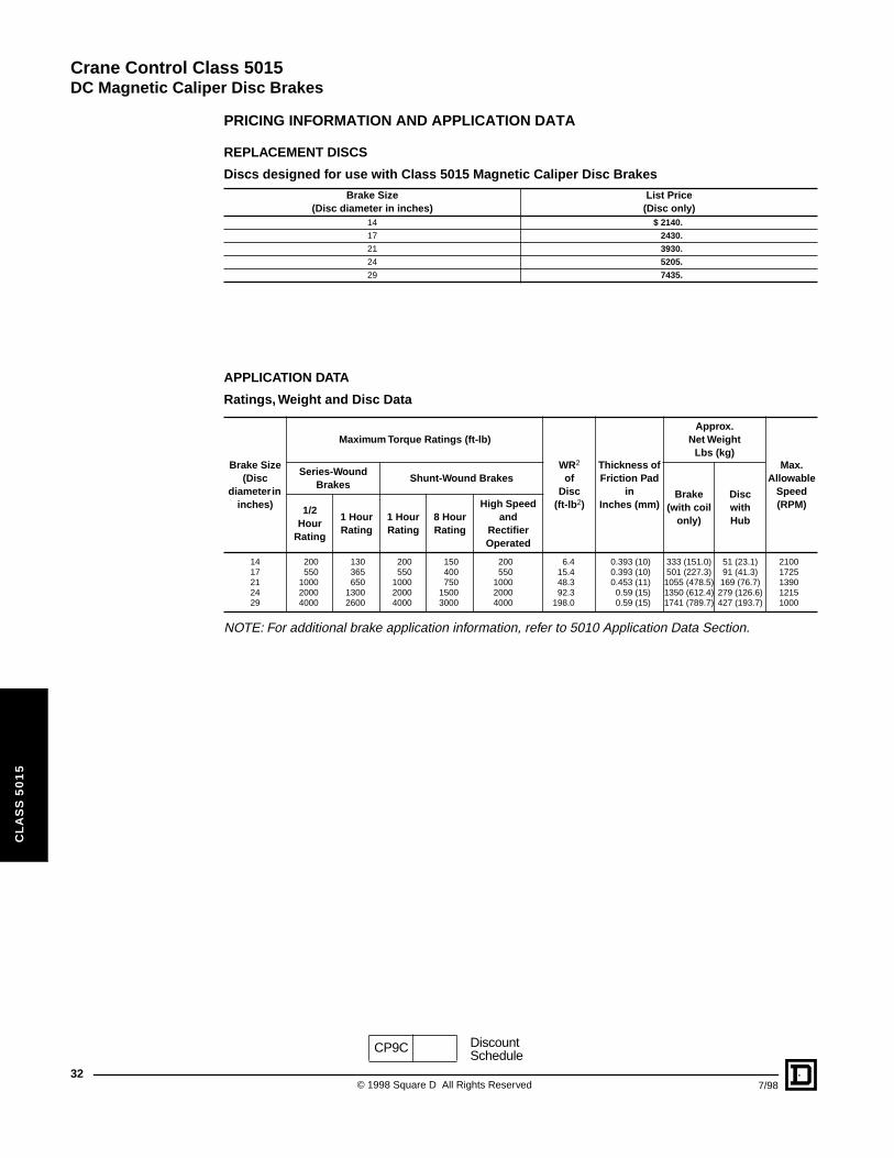
PRICING INFORMATION AND APPLICATION DATA
REPLACEMENT DISCS
APPLICATION DATA
NOTE: For additional brake application information, refer to 5010 Application Data Section.
Discs designed for use with Class 5015 Magnetic Caliper Disc Brakes
Brake Size(Disc diameter in inches)
List Price(Disc only)
14 $ 2140.
17 2430.
21 3930.
24 5205.
29 7435.
Ratings, Weight and Disc Data
Brake Size(Disc
diameter in inches)
Maximum Torque Ratings (ft-lb)
WR2
ofDisc
(ft-lb2)
Thickness of Friction Pad
inInches (mm)
Approx.Net Weight
Lbs (kg)Max.
AllowableSpeed (RPM)
Series-Wound Brakes
Shunt-Wound Brakes
Brake (with coil
only)
DiscwithHub
1/2 Hour
Rating
1 Hour Rating
1 Hour Rating
8 Hour Rating
High Speed and
Rectifier Operated
1417212429
200550
100020004000
130365650
13002600
200550
100020004000
150400750
15003000
200550
100020004000
6.415.448.392.3
198.0
0.393 (10)0.393 (10)0.453 (11)0.59 (15)0.59 (15)
333 (151.0)501 (227.3)
1055 (478.5)1350 (612.4)1741 (789.7)
51 (23.1)91 (41.3)
169 (76.7)279 (126.6)427 (193.7)
21001725139012151000
CP9C DiscountSchedule
© 1998 Square D All Rights Reserved 7/98
Crane Control Class 5015DC Magnetic Caliper Disc Brakes
CL
AS
S 5
01
5
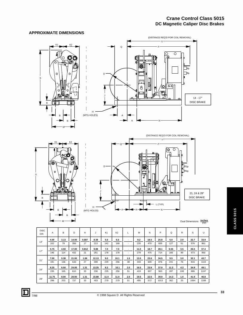
APPROXIMATE DIMENSIONS
DISC
DIA
14"
29"
24"
21"
17"
4.00
5.75
7.50
9.25
11.75
33.9
37.4
43.7
49.1
46.8
22.7
26.5
32.1
34.9
41.9
2.0
3.5
3.0
4.3
1.0
5.0
6.55
9.5
11.3
14.3
25.8
28.1
34.5
37.9
39.9
18.5
18.7
23.6
23.9
22.5
9.2
11.0
13.5
16.5
19.5
-
-
1.5
2.0
2.0
6.6
7.0
10.1
10.1
11.0
5.6
7.0
9.0
9.3
11.0
8.38
9.88
12.13
13.25
15.88
0.687
0.812
1.06
1.31
1.31
14.00
17.00
21.00
24.00
29.00
3.13
4.50
5.38
6.50
8.00
102
146
191
235
298
861
950
1110
1247
1188
576
673
815
886
1064
51
89
76
108
25
127
166
241
287
362
655
714
876
963
1013
470
475
600
607
572
235
279
343
419
495
-
-
38
51
51
168
178
256
256
279
142
178
229
235
279
213
251
308
336
403
17
21
27
33
33
356
432
533
610
737
79
114
136
165
203
A USRQPNMLK2K1JHDB
P
U
QK1 K2
B
B
R
M
A A N
S
J
L (TYP)
(DISTANCE REQ'D FOR COIL REMOVAL)
(MTG HOLES)
H
D
21, 24 & 29"
DISC BRAKE
K1 K2
R
B
B
M
Q P
U
A
A N
S
J
(DISTANCE REQ'D FOR COIL REMOVAL)
(MTG HOLES)
H
D
14 - 17"
DISC BRAKE
Dual Dimensions inchesmm
337/98 © 1998 Square D All Rights Reserved
Crane Control Class 5015DC Magnetic Caliper Disc Brakes
34
CL
AS
S 5
01
5
© 1998 Square D All Rights Reserved 7/98
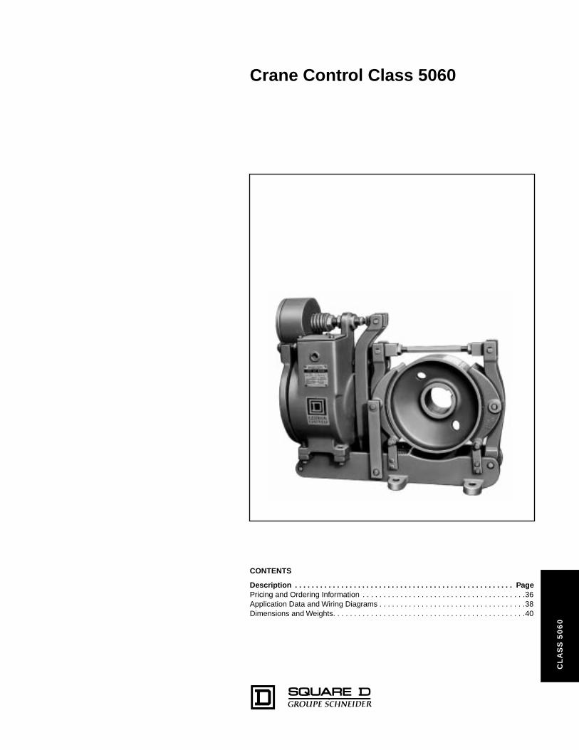
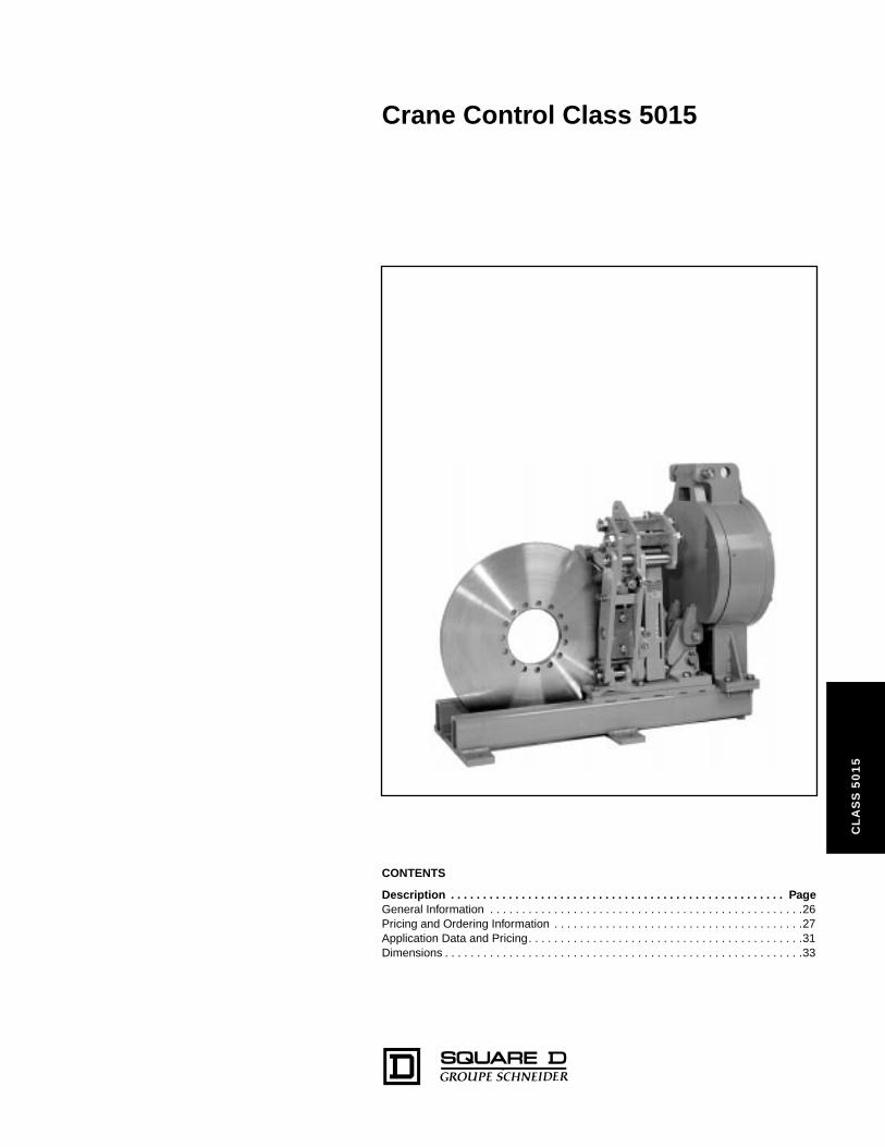
Crane Control Class 5060
06
0
CONTENTSDescription . . . . . . . . . . . . . . . . . . . . . . . . . . . . . . . . . . . . . . . . . . . . . . . . . . . . PagePricing and Ordering Information . . . . . . . . . . . . . . . . . . . . . . . . . . . . . . . . . . . . . . .36Application Data and Wiring Diagrams . . . . . . . . . . . . . . . . . . . . . . . . . . . . . . . . . . .38Dimensions and Weights. . . . . . . . . . . . . . . . . . . . . . . . . . . . . . . . . . . . . . . . . . . . . .40
CL
AS
S 5
Crane Control Class 5060
Adjustable Torque Drum Brakes
36
CL
AS
S 5
06
0
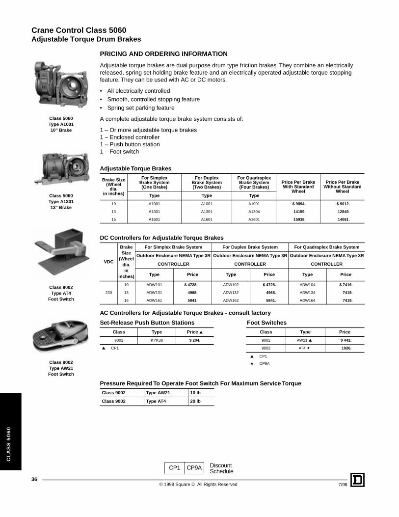
Class 5060Type A100110" Brake
Class 5060Type A130113" Brake
Class 9002Type AT4
Foot Switch
Class 9002Type AW21Foot Switch
PRICING AND ORDERING INFORMATION
Adjustable torque brakes are dual purpose drum type friction brakes. They combine an electrically released, spring set holding brake feature and an electrically operated adjustable torque stopping feature. They can be used with AC or DC motors.
• All electrically controlled• Smooth, controlled stopping feature• Spring set parking feature
A complete adjustable torque brake system consists of:
1 – Or more adjustable torque brakes1 – Enclosed controller1 – Push button station1 – Foot switch
AC Controllers for Adjustable Torque Brakes - consult factory
▲ CP1
a CP9A
Adjustable Torque Brakes
Brake Size(Wheel
dia.in inches)
For Simplex Brake System(One Brake)
For Duplex Brake System (Two Brakes)
For Quadraplex Brake System (Four Brakes)
Price Per Brake With Standard
Wheel
Price Per BrakeWithout Standard
WheelType Type Type
10 A1001 A1001 A1001 $ 9894. $ 9012.
13 A1301 A1301 A1304 14159. 12849.
16 A1601 A1601 A1601 15938. 14081.
DC Controllers for Adjustable Torque Brakes
VDC
Brake Size
(Wheeldia.in
inches)
For Simplex Brake System For Duplex Brake System For Quadraplex Brake System
Outdoor Enclosure NEMA Type 3R Outdoor Enclosure NEMA Type 3R Outdoor Enclosure NEMA Type 3R
CONTROLLER CONTROLLER CONTROLLER
Type Price Type Price Type Price
230
10 ADW101 $ 4728. ADW102 $ 4728. ADW104 $ 7419.
13 ADW131 4968. ADW132 4968. ADW134 7419.
16 ADW161 5841. ADW162 5841. ADW164 7419.
Set-Release Push Button Stations Foot Switches
Class Type Price ▲ Class Type Price
9001 KYK38 $ 204. 9002 AW21 ▲ $ 442.
▲ CP1 9002 AT4 a 1026.
Pressure Required To Operate Foot Switch For Maximum Service Torque
Class 9002 Type AW21 10 lb
Class 9002 Type AT4 20 lb
CP1 CP9A DiscountSchedule
© 1998 Square D All Rights Reserved 7/98
Crane Control Class 5060
Adjustable Torque Drum Brakes
7/98
CL
AS
S 5
06
0
ORDERING INFORMATION
Ordering Information Required:
1. For adjustable torque brake:
a. Classb. Typec. Torque if different from standard
2. For brake controller:
a. Classb. Typec. Information on system – cab, pendant and radio operation
3. For push button station and foot switch (if required):
a. Classb. Type
4. For brake wheel purchased with brake:Supply the dimensions required for ordering wheels in the Class 5010 catalog sheets.
5. For brake wheels only:When purchased separately, the brake wheel is considered to be a replacement part. Furnish the original Square D brake wheel part number or the dimensions required for ordering wheels in the Class 5010 catalog sheets.
37© 1998 Square D All Rights Reserved
Crane Control Class 5060
Adjustable Torque Drum Brakes
38
CL
AS
S 5
06
0
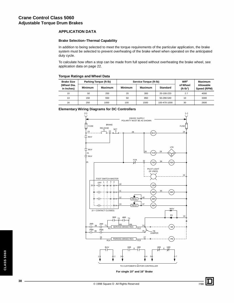
APPLICATION DATA
Brake Selection–Thermal Capability
In addition to being selected to meet the torque requirements of the particular application, the brake system must be selected to prevent overheating of the brake wheel when operated on the anticipated duty cycle.
To calculate how often a stop can be made from full speed without overheating the brake wheel, see application data on page 22.
Elementary Wiring Diagrams for DC Controllers
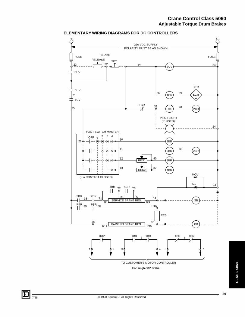
Torque Ratings and Wheel Data
Brake Size(Wheel Dia. in Inches)
Parking Torque (ft-lb) Service Torque (ft-lb) WR2
of Wheel(ft-lb2)
Maximum Allowable
Speed (RPM)Minimum Maximum Minimum Maximum Standard
10 50 200 20 300 20-100-220 2.7 4000
13 150 550 50 850 50-290-540 10 3300
16 250 1000 100 1500 100-470-1000 30 2600
8
TO CUSTOMER'S MOTOR CONTROLLER
230VDC SUPPLYPOLARITY MUST BE AS SHOWN
BUV 1BR1BR1BR1BR
1 532 4 7
6
BUV
PBR 25 PBR
BUV
1BR
3BR
4BR
2BR 2BR
BUV
PARKING BRAKE RES
SERVICE BRAKE RES
D1
27
244BR3BR T2
15
R5 R9
PBR PBR
(X = CONTACT CLOSED)
13
FOOT SWITCH MASTER
T3
1 2 3 4OFF26
24
RES1
RES2
T12BR 2BR
BUV
25
1TR
TCR
TCR
10
11
12
14
23
26
24
38
39
32
29
34
35
37
40
21
26
(IF USED)PILOT LIGHT
RELEASE SET
22
BRAKE
TBJUMPER
SB
PB
MOV
(+) (–)
FUSE FUSE
R1
R14
R12
R15
For single 10" and 16" Brake
© 1998 Square D All Rights Reserved 7/98
Crane Control Class 5060
Adjustable Torque Drum Brakes
7/98
CL
AS
S 5
06
0
ELEMENTARY WIRING DIAGRAMS FOR DC CONTROLLERS
8
TO CUSTOMER'S MOTOR CONTROLLER
230 VDC SUPPLYPOLARITY MUST BE AS SHOWN
BUV 1BR1BR1BR1BR
1 532 4 7
6
BUV
PBR 25 PBR
BUV
1BR
3BR
4BR
2BR 2BR
BUV
PARKING BRAKE RES
SERVICE BRAKE RES
D1
27
244BR3BR T2
R16
RES
R9
R15
R1
R14
R5 R7
PBR PBR
(X = CONTACT CLOSED)
13
FOOT SWITCH MASTER
T3
1 2 3 4OFF26
24
RES1
RES2
T12BR 2BR
BUV
25
1TR
TCR
TCR
10
11
12
14
23
26
24
(–)
38
39 39
32
29
34
35
37
40
21
26
(IF USED)PILOT LIGHT
RELEASE SET
22
BRAKE
SB
PB
MOV
FUSE
(+)
FUSE
For single 13" Brake
39© 1998 Square D All Rights Reserved
Crane Control Class 5060
Adjustable Torque Drum Brakes
40
CL
AS
S 5
06
0
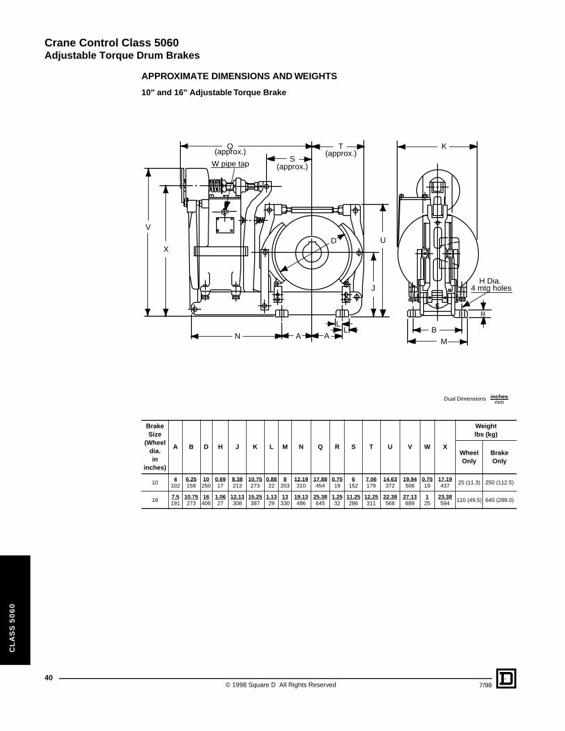
APPROXIMATE DIMENSIONS AND WEIGHTS
10" and 16" Adjustable Torque Brake
Brake Size
(Wheeldia.in
inches)
A B D H J K L M N Q R S T U V W X
Weightlbs (kg)
Wheel Only
Brake Only
104
1026.25159
10250
0.6917
8.38213
10.75273
0.8822
8203
12.19310
17.88454
0.7519
6152
7.06179
14.63372
19.94506
0.7519
17.19437
25 (11.3) 250 (112.5)
167.5191
10.75273
16406
1.0627
12.13308
15.25387
1.1329
13330
19.13486
25.38645
1.2532
11.25286
12.25311
22.38568
27.13689
125
23.38594
110 (49.5) 640 (288.0)
M
BL
LA
J
D U
R
H Dia.4 mtg holes
K
S
T(approx.)
(approx.)
(approx.)Q
W pipe tap
V
X
N A
Dual Dimensions inchesmm
© 1998 Square D All Rights Reserved 7/98
Crane Control Class 5060
Adjustable Torque Drum Brakes
7/98
CL
AS
S 5
06
0
APPROXIMATE DIMENSIONS AND WEIGHTS
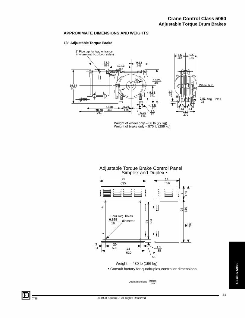
13" Adjustable Torque Brake
25635
14356
Four mtg. holes0.625
16diameter 21 53
3
251
20508 24
610
1.538
251
Weight – 430 lb (196 kg)
24 610
31 787
717
8
Adjustable Torque Brake Control PanelSimplex and Duplex •
• Consult factory for quadruplex controller dimensions
1" Pipe tap for lead entranceinto terminal box (both sides)
23.0584 10.13
257
9.63245
13.0330
19.25489
9.88251
1.025
1.0255.75
146
5.75146
18.3146528.88
734
19.94507
6.5165
6.5165
0.8121
1.025
11.0279
4.5114
4.5114
Wheel hub
Mtg. Holes
Weight of wheel only – 60 lb (27 kg)Weight of brake only – 570 lb (259 kg)
Dual Dimensions inchesmm
41© 1998 Square D All Rights Reserved
Crane Control Class 5060
Adjustable Torque Drum Brakes
42
CL
AS
S 5
06
0
APPROXIMATE DIMENSIONS AND WEIGHTS
3 holes for 0.318
dia. mtg. screw
3.5 89
4.5
114
5.811488.56
217
3/4-14 pipe tap
5.81148 0.31
8
0.8722
2.8
171
Weight – 5 lb (2 kg)
AW21 Foot Switch
Weight – 18 lb (8 kg)7.1
180
8.0203
13.5343
4102
0.410
mtg. holes
4102 6.6
168
1.333
7.0
178
1.436
Dia.1.641
4.3109
6.7
170
12.8
325
To r
em
ove
cove
r
AT4 Foot Switch
Dual Dimensions inchesmm
© 1998 Square D All Rights Reserved 7/98
Crane Control Class 6121
CL
AS
S 6
12
1
CATALOG CONTENTS
Description . . . . . . . . . . . . . . . . . . . . . . . . . . . . . . . . . . . . . . . . . . . . . . . . . . . . PageGeneral Information and Pricing . . . . . . . . . . . . . . . . . . . . . . . . . . . . . . . . . . . . . . . .44Controller Modifications and Application Data . . . . . . . . . . . . . . . . . . . . . . . . . . . . .48Wiring Diagrams . . . . . . . . . . . . . . . . . . . . . . . . . . . . . . . . . . . . . . . . . . . . . . . . . . . .54Application Data . . . . . . . . . . . . . . . . . . . . . . . . . . . . . . . . . . . . . . . . . . . . . . . . . . . .56Dimensions and Weights. . . . . . . . . . . . . . . . . . . . . . . . . . . . . . . . . . . . . . . . . . . . . .58Rectified DC Constant Potential HWR Hoist Control . . . . . . . . . . . . . . . . . . . . . . . .60DC Mill Auxiliary Control . . . . . . . . . . . . . . . . . . . . . . . . . . . . . . . . . . . . . . . . . . . . . .62
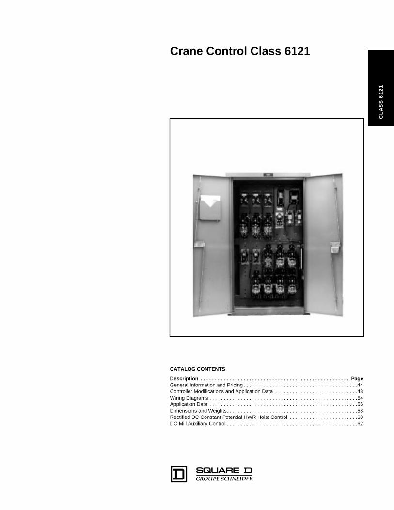
Crane Control Class 6121
FRONTLINE® DC Crane Control
44
CL
AS
S 6
12
1
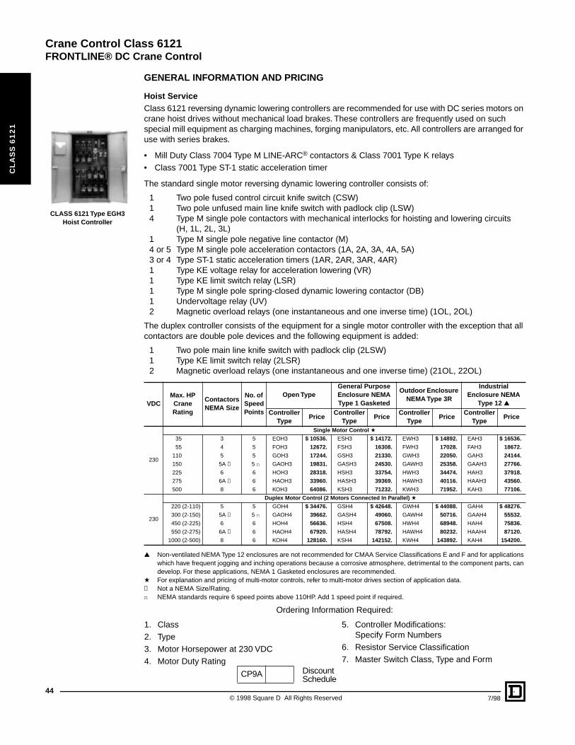
CLASS 6121 Type EGH3 Hoist Controller
GENERAL INFORMATION AND PRICING
Hoist ServiceClass 6121 reversing dynamic lowering controllers are recommended for use with DC series motors on crane hoist drives without mechanical load brakes. These controllers are frequently used on such special mill equipment as charging machines, forging manipulators, etc. All controllers are arranged for use with series brakes.
• Mill Duty Class 7004 Type M LINE-ARC® contactors & Class 7001 Type K relays• Class 7001 Type ST-1 static acceleration timer
The standard single motor reversing dynamic lowering controller consists of:
1 Two pole fused control circuit knife switch (CSW)1 Two pole unfused main line knife switch with padlock clip (LSW)4 Type M single pole contactors with mechanical interlocks for hoisting and lowering circuits
(H, 1L, 2L, 3L)1 Type M single pole negative line contactor (M)4 or 5 Type M single pole acceleration contactors (1A, 2A, 3A, 4A, 5A)3 or 4 Type ST-1 static acceleration timers (1AR, 2AR, 3AR, 4AR)1 Type KE voltage relay for acceleration lowering (VR)1 Type KE limit switch relay (LSR)1 Type M single pole spring-closed dynamic lowering contactor (DB)1 Undervoltage relay (UV)2 Magnetic overload relays (one instantaneous and one inverse time) (1OL, 2OL)
The duplex controller consists of the equipment for a single motor controller with the exception that all contactors are double pole devices and the following equipment is added:
1 Two pole main line knife switch with padlock clip (2LSW)1 Type KE limit switch relay (2LSR)2 Magnetic overload relays (one instantaneous and one inverse time) (21OL, 22OL)
▲ Non-ventilated NEMA Type 12 enclosures are not recommended for CMAA Service Classifications E and F and for applications which have frequent jogging and inching operations because a corrosive atmosphere, detrimental to the component parts, can develop. For these applications, NEMA 1 Gasketed enclosures are recommended.
a For explanation and pricing of multi-motor controls, refer to multi-motor drives section of application data.✝ Not a NEMA Size/Rating.n NEMA standards require 6 speed points above 110HP. Add 1 speed point if required.
Ordering Information Required:
VDCMax. HP Crane Rating
Contactors NEMA Size
No. of Speed Points
Open TypeGeneral Purpose Enclosure NEMA Type 1 Gasketed
Outdoor Enclosure NEMA Type 3R
Industrial Enclosure NEMA
Type 12 ▲Controller
TypePrice
Controller Type
PriceController
TypePrice
Controller Type
Price
230
Single Motor Control a
35 3 5 EOH3 $ 10536. ESH3 $ 14172. EWH3 $ 14892. EAH3 $ 16536.
55 4 5 FOH3 12672. FSH3 16308. FWH3 17028. FAH3 18672.
110 5 5 GOH3 17244. GSH3 21330. GWH3 22050. GAH3 24144.
150 5A ✝ 5 n GAOH3 19831. GASH3 24530. GAWH3 25358. GAAH3 27766.
225 6 6 HOH3 28318. HSH3 33754. HWH3 34474. HAH3 37918.
275 6A ✝ 6 HAOH3 33960. HASH3 39369. HAWH3 40116. HAAH3 43560.
500 8 6 KOH3 64086. KSH3 71232. KWH3 71952. KAH3 77106.
230
Duplex Motor Control (2 Motors Connected In Parallel) a
220 (2-110) 5 5 GOH4 $ 34476. GSH4 $ 42648. GWH4 $ 44088. GAH4 $ 48276.
300 (2-150) 5A ✝ 5 n GAOH4 39662. GASH4 49060. GAWH4 50716. GAAH4 55532.
450 (2-225) 6 6 HOH4 56636. HSH4 67508. HWH4 68948. HAH4 75836.
550 (2-275) 6A ✝ 6 HAOH4 67920. HASH4 78792. HAWH4 80232. HAAH4 87120.
1000 (2-500) 8 6 KOH4 128160. KSH4 142152. KWH4 143892. KAH4 154200.
1. Class2. Type 3. Motor Horsepower at 230 VDC4. Motor Duty Rating
5. Controller Modifications:Specify Form Numbers
6. Resistor Service Classification7. Master Switch Class, Type and Form
CP9A DiscountSchedule
© 1998 Square D All Rights Reserv
ed 7/98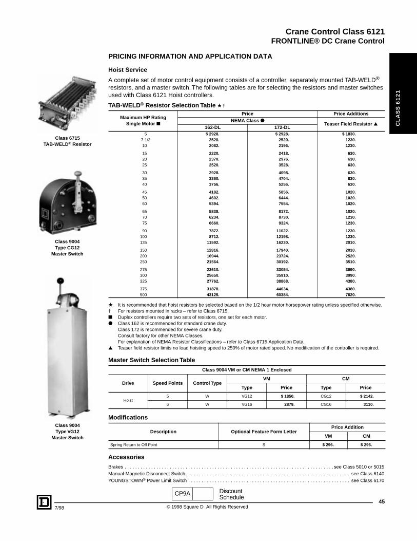
Crane Control Class 6121
FRONTLINE® DC Crane Control
7/98
CL
AS
S 6
12
1
Class 6715TAB-WELD® Resistor
Class 9004Type CG12
Master Switch
Class 9004Type VG12
Master Switch
PRICING INFORMATION AND APPLICATION DATA
Hoist Service
A complete set of motor control equipment consists of a controller, separately mounted TAB-WELD® resistors, and a master switch. The following tables are for selecting the resistors and master switches used with Class 6121 Hoist controllers.
★ It is recommended that hoist resistors be selected based on the 1/2 hour motor horsepower rating unless specified otherwise.† For resistors mounted in racks – refer to Class 6715.■ Duplex controllers require two sets of resistors, one set for each motor.● Class 162 is recommended for standard crane duty.
Class 172 is recommended for severe crane duty.Consult factory for other NEMA Classes.For explanation of NEMA Resistor Classifications – refer to Class 6715 Application Data.
▲ Teaser field resistor limits no load hoisting speed to 250% of motor rated speed. No modification of the controller is required.
Accessories
Brakes . . . . . . . . . . . . . . . . . . . . . . . . . . . . . . . . . . . . . . . . . . . . . . . . . . . . . . . . . . . . . . . . . . . . . . . . . . . . . . . see Class 5010 or 5015Manual-Magnetic Disconnect Switch . . . . . . . . . . . . . . . . . . . . . . . . . . . . . . . . . . . . . . . . . . . . . . . . . . . . . . . . . . . . . . see Class 6140YOUNGSTOWN® Power Limit Switch . . . . . . . . . . . . . . . . . . . . . . . . . . . . . . . . . . . . . . . . . . . . . . . . . . . . . . . . . . . . . see Class 6170
TAB-WELD® Resistor Selection Table ★ †
Maximum HP Rating Single Motor ■
Price Price AdditionsNEMA Class ●
Teaser Field Resistor ▲162-DL 172-DL
5 $ 2928. $ 2928. $ 1830.7-1/2 2520. 2520. 1230.10 2082. 2196. 1230.
15 2220. 2418. 630.20 2370. 2976. 630.25 2520. 3528. 630.
30 2928. 4098. 630.35 3360. 4704. 630.40 3756. 5256. 630.
45 4182. 5856. 1020.50 4602. 6444. 1020.60 5394. 7554. 1020.
65 5838. 8172. 1020.70 6234. 8730. 1230.75 6660. 9324. 1230.
90 7872. 11022. 1230.100 8712. 12198. 1230.135 11592. 16230. 2010.
150 12816. 17940. 2010.200 16944. 23724. 2520.250 21564. 30192. 3510.
275 23610. 33054. 3990.300 25650. 35910. 3990.325 27762. 38868. 4380.
375 31878. 44634. 4380.500 43125. 60384. 7620.
Master Switch Selection Table
Class 9004 VM or CM NEMA 1 Enclosed
Drive Speed Points Control TypeVM CM
Type Price Type Price
Hoist5 W VG12 $ 1850. CG12 $ 2142.
6 W VG16 2879. CG16 3110.
Modifications
Description Optional Feature Form LetterPrice Addition
VM CM
Spring Return to Off Point S $ 296. $ 296.
CP9A Discount
45© 1998 Square D All Rights Reserved
Schedule

Crane Control Class 6121
FRONTLINE® DC Crane Control
46
CL
AS
S 6
12
1
Class 6121 Type EGR3 Bridge Controller
GENERAL INFORMATION AND PRICING
Bridge or Trolley Service
Class 6121 reversing plugging controllers are recommended for use with DC series motors on crane travel drives. These controllers are frequently used on such special mill equipment as charging machines, forging manipulators, etc. All controllers are arranged for use with series brakes. Shunt brakes can be used when a brake relay is added to the controller.
• Mill Duty Class 7004 Type M LINE-ARC® contactors & Class 7001 Type K relays• Class 7001 Type ST-1 static acceleration timers
The standard single motor reversing dynamic lowering control consists of:
1 Two pole fused control circuit knife switch (CSW)1 Two pole unfused main line knife switch with padlock clip (LSW)4 Type M single pole directional contactors with mechanical interlocks (1F, 2F, 1R, 2R)1 Type M single pole negative line contactor (M)4 or 5 Type M single pole acceleration contactors (including one for plugging) (1A, 2A, 3A, P)3 or 4 Type ST-1 static acceleration timers (1AR, 2AR, 3AR, 4AR)1 Type KP rectifier-plugging relay (PR)1 Undervoltage relay (UV)2 Magnetic overload relays (one instantaneous and one inverse time) (1OL, 2OL)
The duplex controller consists of the equipment for a single motor controller with the exception that all contactors are double pole devices and the following equipment is added:
1 Two pole main line knife switch with padlock clip (2LSW)1 Type KP rectifier-plugging relay (2PR)2 Magnetic overload relays (one instantaneous and one inverse time) (21OL, 22OL)
▲ Non-ventilated NEMA Type 12 enclosures are not recommended for CMAA Service Classifications E and F and for applications which have frequent jogging and inching operations because a corrosive atmosphere, detrimental to the component parts, can develop. For these applications, NEMA 1 Gasketed enclosures are recommended.
★ For explanation and pricing of multi-motor controls refer to multi-motor drives section of application data.✝ Not a NEMA Size/Rating.n NEMA standards require 6 speed points above 110HP. Add 1 speed point if required.● For higher horsepowers, consult factory.
Ordering Information Required:
VDCMax. HP Crane
Rating ●
Contactors NEMA Size
No. of Speed Points
Open TypeGeneral Purpose Enclosure NEMA Type 1 Gasketed
Rainproof and Sleet-Resistant
Enclosure NEMA Type 3R
Industrial Enclosure NEMA
Type 12 ▲
Controller Type
PriceController
TypePrice
Controller Type
PriceController
TypePrice
230
Single Motor Control ★
35 3 5 EOR3 $ 9780. ESR3 $ 13416. EWR3 $ 14136. EAR3 $ 15780.
55 4 5 FOR3 11568. FSR3 15204. FWR3 15924. FAR3 17568.
110 5 5 GOR3 15768. GSR3 19854. GWR3 20574. GAR3 22668.
150 5A ✝ 5 n GAOR3 18133. GASR3 22832. GAWR3 23660. GAAR3 26068.
225 6 6 HOR3 25920. HSR3 31356. HWR3 32076. HAR3 35520.
230
Duplex Motor Control (2 Motors Connected in Parallel) ★
70 (2-35) 3 5 EOR4 $ 19560. ESR4 $ 26832. EWR4 $ 28272. EAR4 $ 31560.
110 (2-55) 4 5 FOR4 23136. FSR4 30408. FWR4 31848. FAR4 35136.
220 (2-110) 5 5 GOR4 31536. GSR4 39708. GWR4 41148. GAR4 45336.
300 (2-150) 5A ✝ 5 n GAOR4 36266. GASR4 45664. GAWR4 47320. GAAR4 52136.
450 (2-225) 6 6 HOR4 51840. HSR4 62712. HWR4 64152. HAR4 71040.
1. Class2. Type 3. Motor Horsepower at 230 VDC4. Motor Duty Rating
5. Controller Modifications:Specify Form Numbers
6. Resistor Service Classification7. Master Switch Class, Type and Form
CP9A Discount
© 1998 Square D All Rights Reserv
Schedule
ed 7/98
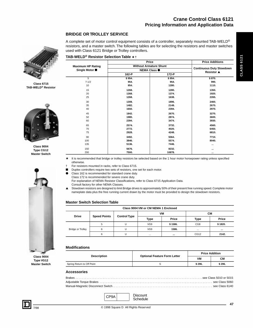
Crane Control Class 6121
Pricing Information and Application Data
7/98
CL
AS
S 6
12
1
Class 6715TAB-WELD® Resistor
Class 9004Type CG12
Master Switch
Class 9004Type VG12
Master Switch
BRIDGE OR TROLLEY SERVICE
A complete set of motor control equipment consists of a controller, separately mounted TAB-WELD® resistors, and a master switch. The following tables are for selecting the resistors and master switches used with Class 6121 Bridge or Trolley controllers.
★ It is recommended that bridge or trolley resistors be selected based on the 1 hour motor horsepower rating unless specified otherwise.
† For resistors mounted in racks, refer to Class 6715.■ Duplex controllers require two sets of resistors, one set for each motor.● Class 162 is recommended for standard crane duty.
Class 172 is recommended for severe crane duty.For explanation of NEMA Resistor Classifications, refer to Class 6715 Application Data. Consult factory for other NEMA Classes.
▲ Slowdown resistors are designed to limit Bridge drives to approximately 50% of their present free running speed. Complete motor nameplate data plus the free running current drawn by the motor must be provided to design the slowdown resistors.
Accessories
Brakes . . . . . . . . . . . . . . . . . . . . . . . . . . . . . . . . . . . . . . . . . . . . . . . . . . . . . . . . . . . . . . . . . . . . . . . . . . . . . . . see Class 5010 or 5015Adjustable Torque Brakes . . . . . . . . . . . . . . . . . . . . . . . . . . . . . . . . . . . . . . . . . . . . . . . . . . . . . . . . . . . . . . . . . . . . . . see Class 5060Manual-Magnetic Disconnect Switch . . . . . . . . . . . . . . . . . . . . . . . . . . . . . . . . . . . . . . . . . . . . . . . . . . . . . . . . . . . . . . see Class 6140
TAB-WELD® Resistor Selection Table ★ †
Maximum HP Rating Single Motor ■
Price Price AdditionsWithout Armature Shunt
Continuous Duty Slowdown Resistor ▲
NEMA Class ●162-P 172-P
5 $ 954. $ 954. $ 870.7-1/2 954. 954. 990.10 954. 1280. 1110.
15 1268. 1280. 1350.20 1268. 1374. 1920.25 1268. 1638. 2265.
30 1308. 1896. 2460.35 1482. 2148. 2670.40 1650. 2394. 2970.
45 1842. 2670. 3270.50 1980. 2874. 3600.60 2394. 3474. 3930.
65 2574. 3732. 4560.70 2772. 4020. 6450.75 2928. 4248. 6810.
90 3492. 5064. 7710.100 3846. 5574. 8040.135 5136. 7446. ...
150 5676. 8232. ...200 7500. 10878. ...
Master Switch Selection Table
Class 9004 VM or CM NEMA 1 Enclosed
Drive Speed Points Control TypeVM CM
Type Price Type Price
Bridge or Trolley
5 U VG9 $ 1586. CG8 $ 1820.
6 U VG9 1586. ... ...
6 U ... ... CG12 2142.
Modifications
Description Optional Feature Form LetterPrice Addition
VM CM
Spring Return to Off Point S $ 296. $ 296.
CP9A DiscountSchedule
47© 1998 Square D All Rights Reserved
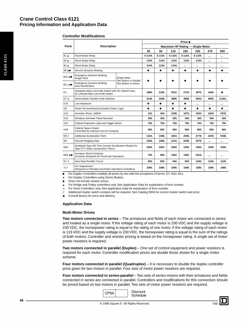
Crane Control Class 6121Pricing Information and Application Data
48
CL
AS
S 6
12
1
■ For Duplex Controllers multiply all prices by two with the exceptions of forms, D7, B10, B11.★ For Duplex Controllers using Series Brakes.● Does not include resistor prices.▲ For Bridge and Trolley controllers only. See Application Data for explanation of form number.❒ For Hoist Controllers only. See Application Data for explanation of form number.✝ Additional master switch contacts will be required. See Catalog 9004 for correct master switch and price.◆ Consult factory for price and delivery.
Application Data
Multi-Motor Drives
Two motors connected in series – The armatures and fields of each motor are connected in series and treated as a single motor. If the voltage rating of each motor is 230 VDC and the supply voltage is 230 VDC, the horsepower rating is equal to the rating of one motor. If the voltage rating of each motor is 115 VDC and the supply voltage is 230 VDC, the horsepower rating is equal to the sum of the ratings of both motors. Controller and resistor pricing is based on the horsepower rating. A single set of motor power resistors is required.
Two motors connected in parallel (Duplex) – One set of control equipment and power resistors is required for each motor. Controller modification prices are double those shown for a single motor scheme.
Four motors connected in parallel (Quadruplex) – It is necessary to double the duplex controller price given for two motors in parallel. Four sets of motor power resistors are required.
Four motors connected in series-parallel – Two sets of series motors with their armatures and fields connected in series are connected in parallel. Controllers and modifications for this connection should be priced based on two motors in parallel. Two sets of motor power resistors are required.
Controller Modifications
Form Description
Price ■
Maximum HP Rating — Single Motor
35 55 110 150 225 275 500
B1 ▲ Shunt Brake Relay $ 1104. $ 1104. $ 1104. $ 1104. $ 1104. ... ...
B3 ▲ Shunt Brake Relay 1104. 1104. 1104. 1104. 1104. ... ...
B4 ▲ Shunt Brake Relay 1104. 1104. 1104. ... ... ... ...
B9 ▲● Service Dynamic Braking ◆ ◆ ◆ ◆ ◆ ◆ ◆
B10 ▲●Emergency Dynamic Braking, Single Point Single Motor
Two Motors in ParallelTwo Motors in Series
◆ ◆ ◆ ◆ ◆ ◆ ◆
B11 ▲●Emergency Dynamic Braking, Auto Deceleration
D1Substitute Main Line Knife Switch with DC Rated Fuses for Unfused Main Line Knife Switch
1880. 2185. 2515. 2725. 3975. 4440. ◆
D7 ★ Series Brake Transfer Knife Switches 2136. 3468. 4896. 4898. 9024. 9845. 11264.
E19 Low Headroom ◆ ◆ ◆ ◆ ... ... ...
G8 Power Terminal Board (Includes Power Lugs) ◆ ◆ ◆ ◆ ◆ ◆ ◆
G15 Ammeter Shunt, 100MV 312. 420. 1008. 1075. 1620. 1620. 2376.
G16 Miniature Ammeter Panel Mounted 300. 300. 300. 300. 300. 300. 300.
G22 Cabinet Inspection Light and Toggle Switch 750. 750. 750. 750. 750. 750. 750.
H18Cabinet Space HeaterControlled by Interlock from M Contactor
660. 660. 660. 660. 660. 660. 660.
M3 ✝ Additional Acceleration Point 1164. 1368. 1824. 2048. 2778. 3240. 5436.
M4 Second Plugging Step 1464. 1668. 2124. 2348. 3078. ... ...
M24Substitute Type SSI Time Current Acceleration Module for Type ST-1 Static Acceleration Timers
1050. 1050. 1050. 1050. 1050. 1050. 1050.
M52 ▲●Armature Shunt Contactor (Controls Slowdown for Floor/Cab Operation)
702. 906. 1362. 1562. 2316. ... ...
R1 ❒ Auto-Stop Rectifier Circuit 830. 830. 940. 940. 1245. 1245. 1245.
Y17Arc Suppressors (Required on Pendant and Radio Operated Controllers)
1080. 1080. 1080. 1080. 1080. 1080. 1080.
CP9A DiscountSchedule
© 1998 Square D All Rights Reserved 7/98
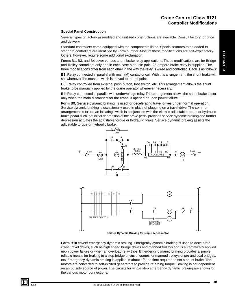
Crane Control Class 6121Controller Modifications
7/98
CL
AS
S 6
12
1
Special Panel Construction
Several types of factory assembled and unitized constructions are available. Consult factory for price and delivery.
Standard controllers come equipped with the components listed. Special features to be added to standard controllers are identified by Form number. Most of these modifications are self-explanatory. Others, however, require some additional explanation.
Forms B1, B3, and B4 cover various shunt brake relay applications. These modifications are for Bridge and Trolley controllers only and in each case a double-pole, 25-ampere brake relay is supplied. The three modifications differ from each other in the way the relay is wired and controlled. Each is as follows:
B1: Relay connected in parallel with main (M) contactor coil. With this arrangement, the shunt brake will set whenever the master switch is moved to the off point.
B3: Relay controlled from external push button, foot switch, etc. This arrangement allows the shunt brake to be manually applied by the crane operator whenever necessary.
B4: Relay connected in parallel with undervoltage relay. The arrangement allows the shunt brake to set only when the main disconnect for the crane is opened or upon power failure.
Form B9, Service dynamic braking, is used for decelerating travel drives under normal operation. Service dynamic braking is occasionally used in place of plugging on a travel drive. The common arrangement is to use an initiating switch in conjunction with the electric adjustable torque or hydraulic brake pedal such that initial depression of the brake pedal provides service dynamic braking and further depression actuates the adjustable torque or hydraulic brake. Service dynamic braking assists the adjustable torque or hydraulic brake.
Form B10 covers emergency dynamic braking. Emergency dynamic braking is used to decelerate crane travel drives, such as high speed bridge drives and manned trolleys and is automatically applied upon power failure or when an overload relay trips. Emergency dynamic braking provides a simple, reliable means for braking to a stop bridge drives of cranes, or manned trolleys of ore and coal bridges, etc. Emergency dynamic braking is applied in about 1/5 the time required to set a shunt brake. The motors are converted to self-excited generators to provide retarding torque. Braking is not dependent on an outside source of power. The circuits for single step emergency dynamic braking are shown for the various motor connections.
INITIATINGCONTACT
DB
RE
S
1R
2F2R
TF
1F
3A P2A 1A
M
+ PR
ITE
MASTER SWITCH
–+
M
DB
TF
TF
DB
P 2F 1R
LSW2OL
INST
1OL
SERIESFIELD
R5ARM
R1ACCEL RES
LSWR4 R2R3
DB
Service Dynamic Braking for single series motor
49© 1998 Square D All Rights Reserved
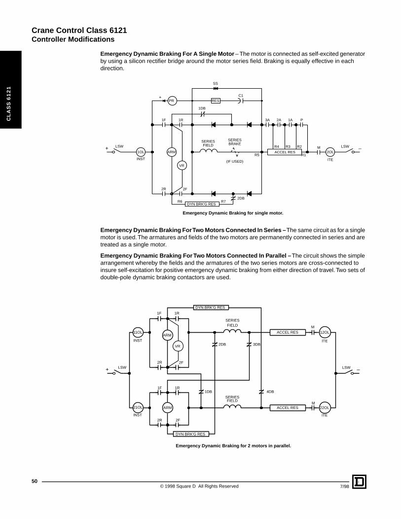
Crane Control Class 6121Controller Modifications
50
CL
AS
S 6
12
1
Emergency Dynamic Braking For A Single Motor – The motor is connected as self-excited generator by using a silicon rectifier bridge around the motor series field. Braking is equally effective in each direction.
Emergency Dynamic Braking For Two Motors Connected In Series – The same circuit as for a single motor is used. The armatures and fields of the two motors are permanently connected in series and are treated as a single motor.
Emergency Dynamic Braking For Two Motors Connected In Parallel – The circuit shows the simple arrangement whereby the fields and the armatures of the two series motors are cross-connected to insure self-excitation for positive emergency dynamic braking from either direction of travel. Two sets of double-pole dynamic braking contactors are used.
C1+PR
1R
2R 2F
1F 3A P2A 1A
M
ITE
RES
SS
–+ LSW
2OL
INST
1OL
SERIES
(IF USED)
SERIESFIELD BRAKE
R5ARM
VR
R1ACCEL RES
LSWR4 R3 R2
R7R6DYN BRK'G RES
2DB
1DB
Emergency Dynamic Braking for single motor.
1R
1R
2R
2R
2F
2F
1F
1F
M
M
ITE
ITE
–+ LSW
12OL
22OL
INST
INST
11OL
21OL
SERIES
SERIES
FIELD
FIELD
ARM
ARM
VR
ACCEL RES
ACCEL RES
LSW
DYN BRK'G RES
DYN BRK'G RES
3DB
4DB
2DB
1DB
Emergency Dynamic Braking for 2 motors in parallel.
© 1998 Square D All Rights Reserved 7/98
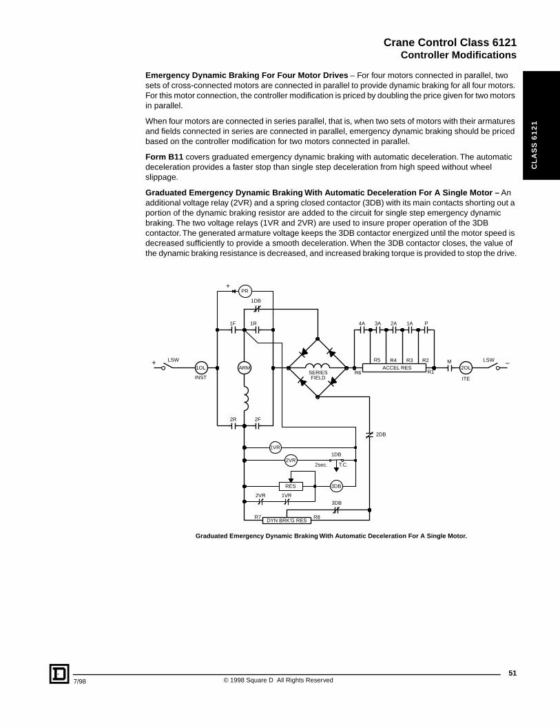
Crane Control Class 6121Controller Modifications
7/98
CL
AS
S 6
12
1
Emergency Dynamic Braking For Four Motor Drives – For four motors connected in parallel, two sets of cross-connected motors are connected in parallel to provide dynamic braking for all four motors. For this motor connection, the controller modification is priced by doubling the price given for two motors in parallel.
When four motors are connected in series parallel, that is, when two sets of motors with their armatures and fields connected in series are connected in parallel, emergency dynamic braking should be priced based on the controller modification for two motors connected in parallel.
Form B11 covers graduated emergency dynamic braking with automatic deceleration. The automatic deceleration provides a faster stop than single step deceleration from high speed without wheel slippage.
Graduated Emergency Dynamic Braking With Automatic Deceleration For A Single Motor – An additional voltage relay (2VR) and a spring closed contactor (3DB) with its main contacts shorting out a portion of the dynamic braking resistor are added to the circuit for single step emergency dynamic braking. The two voltage relays (1VR and 2VR) are used to insure proper operation of the 3DB contactor. The generated armature voltage keeps the 3DB contactor energized until the motor speed is decreased sufficiently to provide a smooth deceleration. When the 3DB contactor closes, the value of the dynamic braking resistance is decreased, and increased braking torque is provided to stop the drive.
1VR2VR
3DB
1VR
2VR1DB
2sec. T.C.
1R
2R 2F
1F 4A P3A 2A 1A
M
RES
+PR
ITE
–+ LSW
2OL
INST
1OLSERIESFIELD
R6ARM
R1ACCEL RES
LSWR2R3R4R5
R8R7DYN BRK'G RES
3DB
2DB
1DB
Graduated Emergency Dynamic Braking With Automatic Deceleration For A Single Motor.
51© 1998 Square D All Rights Reserved
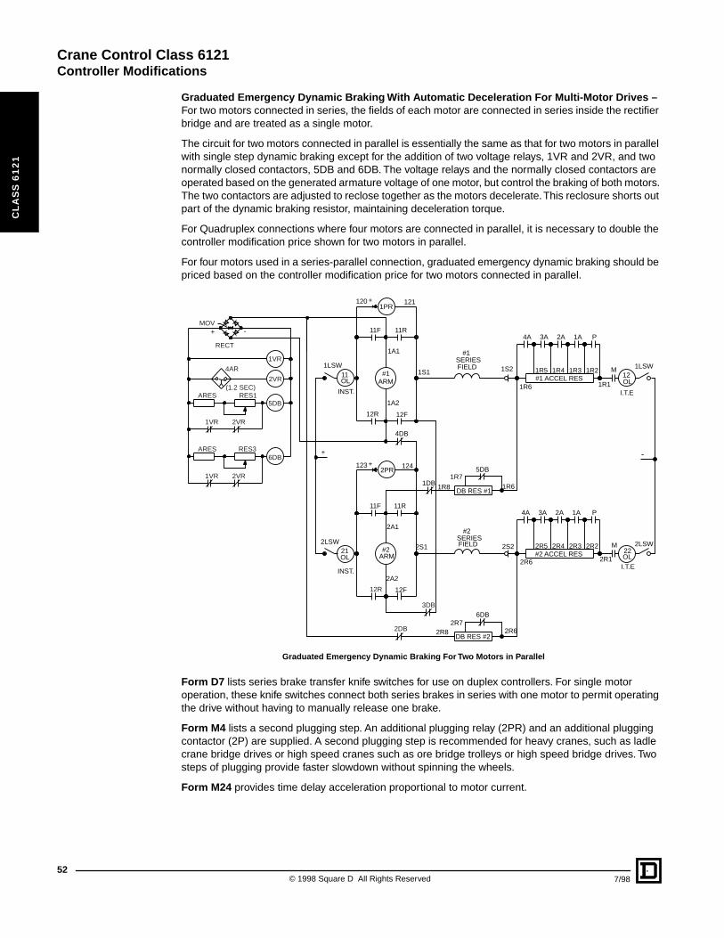
Crane Control Class 6121Controller Modifications
52
CL
AS
S 6
12
1
Graduated Emergency Dynamic Braking With Automatic Deceleration For Multi-Motor Drives –For two motors connected in series, the fields of each motor are connected in series inside the rectifier bridge and are treated as a single motor.
The circuit for two motors connected in parallel is essentially the same as that for two motors in parallel with single step dynamic braking except for the addition of two voltage relays, 1VR and 2VR, and two normally closed contactors, 5DB and 6DB. The voltage relays and the normally closed contactors are operated based on the generated armature voltage of one motor, but control the braking of both motors. The two contactors are adjusted to reclose together as the motors decelerate. This reclosure shorts out part of the dynamic braking resistor, maintaining deceleration torque.
For Quadruplex connections where four motors are connected in parallel, it is necessary to double the controller modification price shown for two motors in parallel.
For four motors used in a series-parallel connection, graduated emergency dynamic braking should be priced based on the controller modification price for two motors connected in parallel.
Form D7 lists series brake transfer knife switches for use on duplex controllers. For single motor operation, these knife switches connect both series brakes in series with one motor to permit operating the drive without having to manually release one brake.
Form M4 lists a second plugging step. An additional plugging relay (2PR) and an additional plugging contactor (2P) are supplied. A second plugging step is recommended for heavy cranes, such as ladle crane bridge drives or high speed cranes such as ore bridge trolleys or high speed bridge drives. Two steps of plugging provide faster slowdown without spinning the wheels.
Form M24 provides time delay acceleration proportional to motor current.
+ -
1VR
2VR
5DB
6DB
1VR
1VR
RES1
RES3
ARES
ARES
2VR
2VR
2DB
3DB
1R8
1R7
2R7
5DB
6DB
1R6
2R62R8
4DB
1DB
4AR
MOV
RECT
(1.2 SEC)
11R
12R
11R
12F
12F12R
11F
11FP
P
3A
3A
2A4A
4A
DB RES #1
DB RES #2
2A
1A
1A
M
M
2PR
1PR
+
+
+
-
1LSW
INST.
11OL
12OL
22OL
123 124
1A1
2A1
1A2
2A2
1S1
2S1SERIES
SERIES
#2
#1
FIELD
FIELD
ARM
ARM
#1
#2
#1 ACCEL RES
#2 ACCEL RES
2LSW
1LSW
21
INST.
OL
2LSW2S2
1S2
121
1R1
2R1
1R2
2R2
1R3
2R3
1R41R5
2R42R5
1R6
2R6I.T.E
I.T.E
120
Graduated Emergency Dynamic Braking For Two Motors in Parallel
© 1998 Square D All Rights Reserved 7/98

Crane Control Class 6121Application Data
7/98
CL
AS
S 6
12
1
Form M52 is an armature shunt contactor for use on Bridge and Trolley controllers only. This modification consists of a single pole normally open contactor of equal NEMA Size to the contactors in the basic controller. The operation is as follows:
The contactor is arranged to provide slowdown of bridge drives during floor operation of cab/floor operated cranes. A customer supplied contact, maintained closed during floor operation, initiates the slowdown.This modification is to be used with NEMA Class 162P or Class 172P accelerating resistors plus a continuous duty bridge slowdown resistor.
Form R1 Auto-Stop Rectifier circuit is used on hoist applications. The series DC brake is set by returning the master switch to the off position during normal running conditions. In a power failure situation the brake will set if the controller is in hoist mode. If however, the standard controller is in lower mode, regenerative power from the DC motor will keep the series brake open and allow the load to be safely lowered. With the Auto-Stop Rectifier circuit modification, the series brake will work as usual in normal running conditions. In a power failure situation, the brake will automatically set in both hoist and lowering modes.
0
50
100
150
200
50
100
150
200
1-L
5-H
4-H
3-H
2-H
1-H
2-L
3-L4-L
5-L
200
150
100
50
50 100 150
50 100 150
FIFTH
FOURTH
THIRD
SECOND
FIRS
T
230 VDCCRANE EFFICIENCY 90%100% CRANE LOAD EQUALS100% MOTOR LOAD100%SPEED EQUALS RATEDMOTOR SPEED AT 230 VOLTS
CRANE LOAD IN % OFMOTOR FULL LOAD
FOR
WA
RD
OR
RE
VE
RS
E S
PE
ED
IN %
OF
RA
TED
SP
EE
D
Crane Travel Speed vs. Load Performance for Class 6121 Reversing Plugging
Crane Hook Speed vs. Load Performancefor Class 6121 Dynamic Lowering Hoist
LOW
ER
ING
SP
EE
D IN
% O
F R
ATE
D S
PE
ED
HO
ISTI
NG
SP
EE
D IN
% O
F R
ATE
D S
PE
ED
HOOK LOAD IN %
OF MOTOR FULL LOAD
HOISTING
DYNAMICLOWERING
230 VDCCRANE EFFICIENCY 90%100% CRANE LOAD EQUALS100% MOTOR LOAD100%SPEED EQUALS RATEDMOTOR SPEED AT 230 VOLTS
53© 1998 Square D All Rights Reserved
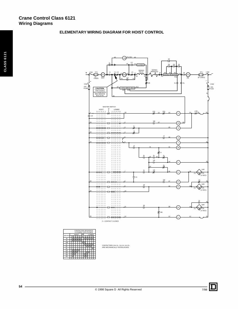
Crane Control Class 6121Wiring Diagrams
54
CL
AS
S 6
12
1
ELEMENTARY WIRING DIAGRAM FOR HOIST CONTROL
42
Y5
A2A1H Y1 LS LS
(IF USED)(IFUSED)
1FU 2FU
OFF12345 1 2 3 4 5
CONTACTOR SEQUENCEX=POWER TIPS CLOSED
HOIST LOWER
4A
MH
DB1L2L3L1A2A3A
DEVICE
20
29
CAUTION
UV
VR
M
1A
H
DB
3L
2L
2A
3A
4A
1L
LSR2OL1OL
1L
H
2L
3L
VR
1A
DB
H
H
2L 3L
VR
1L
DB
2A
3A
1L
(1) (3)
3AR
(1) (3)
2AR
(1) (3)
1AR
H
1A
DB
1
2
3
4
5
6
31 31
27
30
22 23
28
24
28
21
33
33
32
34
7
8
9
35 36
38
37
10
10
11
12
39
12
40
41
X = CONTACT CLOSED
20
20
20
20
20
20
TWO SHOESRECOMMENDED
SEE SERVICEBULLETIN
ARM
SERIESFIELD
1OL
INST
1LLS RES
LSY3
Y4
LSRPU 55V
LSY6 Y2
DB
ACCEL RESISTOR
R7 R10
R9R8
SERIESBRAKE(S)
B
R5
DYN. BRK'G RES
R1R2R3R4
4A
3A 2A 1A
M
3L2L
2OL
ITE
43
UV
5 4 3 2 1 1 2 3 4 5HOIST LOWERO
FF
MASTER SWITCH
(.6 SEC)
(.6 SEC)
(.6 SEC)
S1S2 R11
LSW
+CSW
FUSE15A
LSW
–
2625
26
26
26
26
26
FUSE15A
CSW
CONTACTORS 1A & 1L, 3L & H, H & 2L,ARE MECHANICALLY INTERLOCKED.
–+
© 1998 Square D All Rights Reserved 7/98
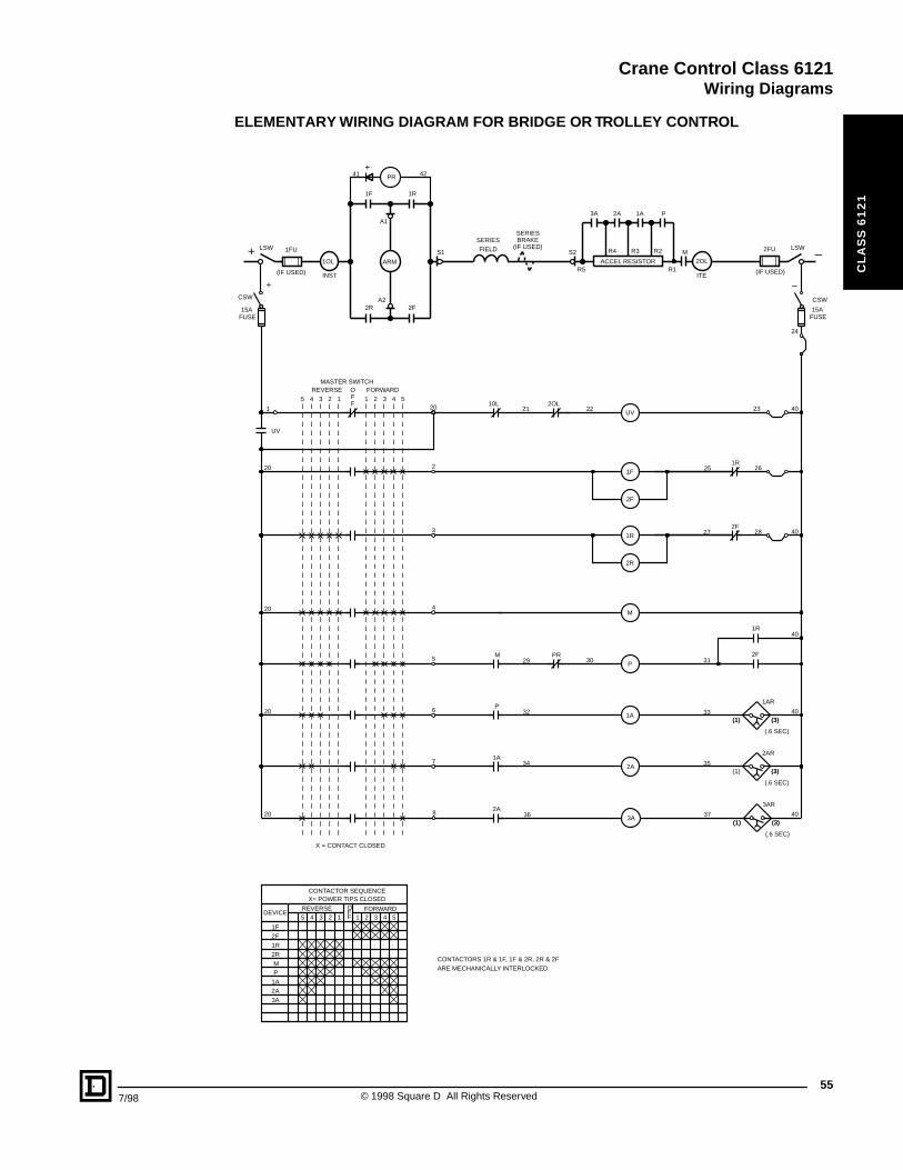
Crane Control Class 6121Wiring Diagrams
7/98
CL
AS
S 6
12
1
ELEMENTARY WIRING DIAGRAM FOR BRIDGE OR TROLLEY CONTROL
CONTACTORS 1R & 1F, 1F & 2R, 2R & 2FARE MECHANICALLY INTERLOCKED.
5 4 3 2 1 1 2 3 4 5
1F2F1R2RMP
1A2A3A
X= POWER TIPS CLOSED
REVERSE FORWARDOFF
CONTACTOR SEQUENCE
DEVICE
1R
2F
1A2A P3A
R1 R5
R4 R2 R3
ACCEL RESISTOR
SERIESFIELD
1OL
INST
1F 1R
2F2RA2
A1
41+
42
S2S1 M 2OL
ITE
LSW
(IF USED)
1FU
ARM
PR
LSW
(IF USED)
2FU
+ –
36 37
35
33
31
40
29
34
32
23
25
27 40
40
40
40
20
2
3
4
5
6
7
8
20
1
20
20
20
FUSE15A
CSW
FUSE15A
CSW
4 55 3 2 1 1 2 3 4REVERSE FORWARD
FFO
MASTER SWITCH
UV
1R
1F
2R
2F
P
M
3A
2A
1A
2OL 10L
2F
1R
PR
2A
1A
P
M
21
30
22
24
28
26
UV
X = CONTACT CLOSED
(3)
(3)
(3)
(1)
(1)
(1)
(.6 SEC)
(.6 SEC)
(.6 SEC)
3AR
2AR
1AR
(3)
(3)
(3)
(1)
(1)
SERIESBRAKE
(IF USED)+ –
55© 1998 Square D All Rights Reserved
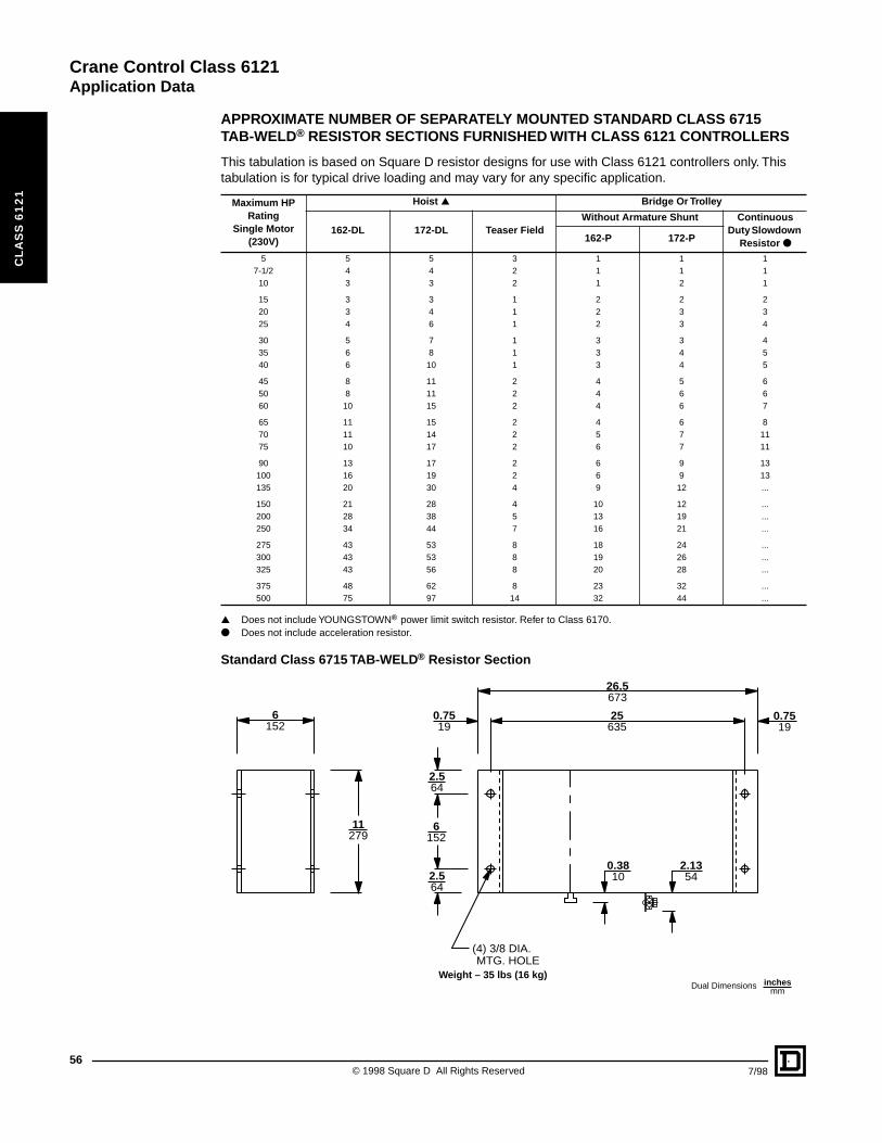
Crane Control Class 6121Application Data
56
CL
AS
S 6
12
1
APPROXIMATE NUMBER OF SEPARATELY MOUNTED STANDARD CLASS 6715 TAB-WELD® RESISTOR SECTIONS FURNISHED WITH CLASS 6121 CONTROLLERS
This tabulation is based on Square D resistor designs for use with Class 6121 controllers only. This tabulation is for typical drive loading and may vary for any specific application.
▲ Does not include YOUNGSTOWN® power limit switch resistor. Refer to Class 6170.● Does not include acceleration resistor.
Standard Class 6715 TAB-WELD® Resistor Section
Maximum HP Rating
Single Motor (230V)
Hoist ▲ Bridge Or Trolley
162-DL 172-DL Teaser FieldWithout Armature Shunt Continuous
Duty Slowdown Resistor ●162-P 172-P
5 5 5 3 1 1 17-1/2 4 4 2 1 1 1
10 3 3 2 1 2 1
15 3 3 1 2 2 220 3 4 1 2 3 325 4 6 1 2 3 4
30 5 7 1 3 3 435 6 8 1 3 4 540 6 10 1 3 4 5
45 8 11 2 4 5 650 8 11 2 4 6 660 10 15 2 4 6 7
65 11 15 2 4 6 870 11 14 2 5 7 1175 10 17 2 6 7 11
90 13 17 2 6 9 13100 16 19 2 6 9 13135 20 30 4 9 12 ...
150 21 28 4 10 12 ...200 28 38 5 13 19 ...250 34 44 7 16 21 ...
275 43 53 8 18 24 ...300 43 53 8 19 26 ...325 43 56 8 20 28 ...
375 48 62 8 23 32 ...500 75 97 14 32 44 ...
6152
6152
25635
0.7519
0.7519
26.5673
2.564
2.564
2.1354
0.3810
(4) 3/8 DIA.MTG. HOLE
11279
Dual Dimensions inchesmm
Weight – 35 lbs (16 kg)
© 1998 Square D All Rights Reserved 7/98
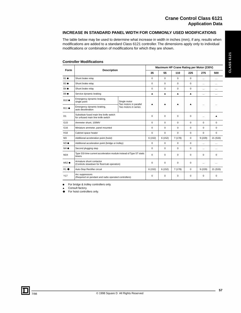
Crane Control Class 6121Application Data
7/98
CL
AS
S 6
12
1
INCREASE IN STANDARD PANEL WIDTH FOR COMMONLY USED MODIFICATIONS
The table below may be used to determine what increase in width in inches (mm), if any, results when modifications are added to a standard Class 6121 controller. The dimensions apply only to individual modifications or combination of modifications for which they are shown.
● For bridge & trolley controllers only.▲ Consult factory.◆ For hoist controllers only.
Controller Modifications
Form DescriptionMaximum HP Crane Rating per Motor (230V)
35 55 110 225 275 500
B1 ● Shunt brake relay 0 0 0 0 ... ...
B3 ● Shunt brake relay 0 0 0 0 ... ...
B4 ● Shunt brake relay 0 0 0 0 ... ...
B9 ● Service dynamic braking ▲ ▲ ▲ ▲ ... ...
B10 ●Emergency dynamic braking, single point Single motor
Two motors in parallelTwo motors in series
▲ ▲ ▲ ▲ ... ...
B11 ●Emergency dynamic braking, auto deceleration
D1Substitute fused main line knife switch for unfused main line knife switch
0 0 0 0 ... ▲
G15 Ammeter shunt, 100MV 0 0 0 0 0 0
G16 Miniature ammeter, panel mounted 0 0 0 0 0 0
H18 Cabinet space heater 0 0 0 0 0 0
M3 Additional acceleration point (hoist) 6 (152) 6 (152) 7 (178) 0 9 (229) 21 (533)
M3 ● Additional acceleration point (bridge or trolley) 0 0 0 0 ... ...
M4 ● Second plugging step 0 0 0 0 ... ...
M24Type SSI time current acceleration module instead of Type ST static timers
0 0 0 0 0 0
M52 ●Armature shunt contactor (Controls slowdown for floor/cab operation)
0 0 0 0 ... ...
R1 ◆ Auto-Stop Rectifier circuit 6 (152) 6 (152) 7 (178) 0 9 (229) 21 (533)
Y17Arc suppressors (Required on pendant and radio operated controllers)
0 0 0 0 0 0
57© 1998 Square D All Rights Reserved
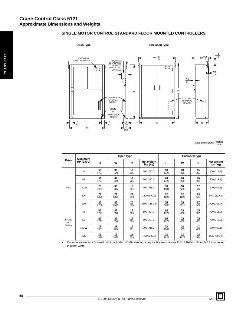
Crane Control Class 6121Approximate Dimensions and Weights
58
CL
AS
S 6
12
1
SINGLE MOTOR CONTROL STANDARD FLOOR MOUNTED CONTROLLERS
▲ Dimensions are for a 5 speed point controller. NEMA standards require 6 speeds above 110HP. Refer to Form M3 for increase in panel width.
Drive Maximum HP (230V)
Open Type Enclosed Type
H W C Net Weight lbs (kg) H W D Net Weight
lbs (kg)
Hoist
3568
172733838
12305
500 (227.3)68
172733
83815
381700 (318.2)
5568
172733838
12305
500 (227.3)68
172733
83815
381700 (318.2)
150 ▲78
198138965
15381
700 (318.2)78
198138
96517
432900 (409.1)
27572
182972
182921533
1300 (590.9)72
182972
182923
5841800 (818.2)
50090
228699
251525635
2600 (1181.8)90
228699
251527
6863700 (1681.8)
Bridge or
Trolley
3568
172733838
12305
500 (227.3)68
172733
83815
381700 (318.2)
5568
172733838
12305
500 (227.3)68
172733
83815
381700 (318.2)
150 ▲78
198138965
15381
700 (318.2)78
198138
96517
432900 (409.1)
22572
182972
182921533
1200 (545.5)72
182972
182923
5841500 (681.8)
Dual Dimensions inchesmm
––
++
INCOMINGLINE TERMINAL
W
4 4 3
4
C
H
W
H
W+
2.5
D
0.5
D+REQUIRED
CLEARANCE TO NEAREST
CONDUCTING SURFACE
CONTROL TERMINAL
BOARD
CONTROL TERMINAL
BOARD
0.62516
MTG. BOLTHOLES
251
64
376
13
102 102 76
102
0.256
Open Type Enclosed Type
© 1998 Square D All Rights Reserved 7/98
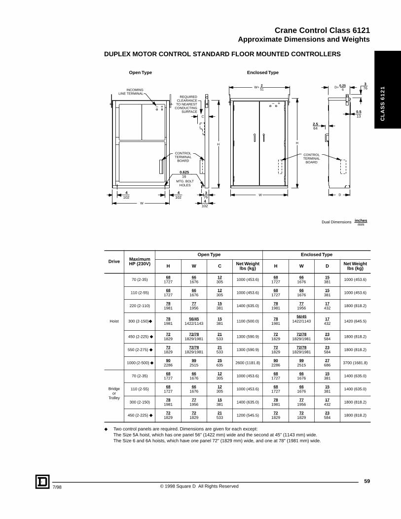
Crane Control Class 6121Approximate Dimensions and Weights
7/98
CL
AS
S 6
12
1
DUPLEX MOTOR CONTROL STANDARD FLOOR MOUNTED CONTROLLERS
◆ Two control panels are required. Dimensions are given for each except:The Size 5A hoist, which has one panel 56" (1422 mm) wide and the second at 45" (1143 mm) wide.The Size 6 and 6A hoists, which have one panel 72" (1829 mm) wide, and one at 78" (1981 mm) wide.
Drive Maximum HP (230V)
Open Type Enclosed Type
H W C Net Weight lbs (kg) H W D Net Weight
lbs (kg)
Hoist
70 (2-35)68
172766
167612305
1000 (453.6)68
172766
167615381
1000 (453.6)
110 (2-55)68
172766
167612305
1000 (453.6)68
172766
167615381
1000 (453.6)
220 (2-110)78
198177
195615381
1400 (635.0)78
198177
195617432
1800 (818.2)
300 (2-150)◆ 78
198156/45
1422/114315381
1100 (500.0)78
1981
56/451422/1143
17432
1420 (645.5)
450 (2-225) ◆ 72
182972/78
1829/198121533
1300 (590.9)72
182972/78
1829/198123584
1800 (818.2)
550 (2-275) ◆ 72
182972/78
1829/198121533
1300 (590.9)72
182972/78
1829/198123584
1800 (818.2)
1000 (2-500) ◆ 90
228699
251525635
2600 (1181.8)90
228699
251527686
3700 (1681.8)
Bridge or
Trolley
70 (2-35)68
172766
167612305
1000 (453.6)68
172766
167615381
1400 (635.0)
110 (2-55)68
172766
167612305
1000 (453.6)68
172766
167615381
1400 (635.0)
300 (2-150)78
198177
195615381
1400 (635.0)78
198177
195617432
1800 (818.2)
450 (2-225) ◆ 72
182972
182921533
1200 (545.5)72
182972
182923584
1800 (818.2)
––
++
W
C
H
W
H
W+
D
D+
REQUIRED CLEARANCE TO NEAREST
CONDUCTING SURFACE
CONTROL TERMINAL
BOARD
CONTROL TERMINAL
BOARD
4 4 3
4
2.5
0.5
0.62516
MTG. BOLTHOLES
251
64
376
13
102 102 76
102
0.256INCOMING
LINE TERMINAL
Open Type Enclosed Type
Dual Dimensions inchesmm
59© 1998 Square D All Rights Reserved

Crane Control Class 6121Rectified DC Constant Potential HWR Hoist Control
60
CL
AS
S 6
12
1
GENERAL INFORMATION AND PRICING
HWR hoist control is recommended for use with DC series motors on AC powered cranes requiring the speed range, accuracy and dependability of a DC powered crane hoist controller. Typically, 230 VDC rated motors are applied at either 230 VDC, 300 VDC, or 360 VDC.
The complete HWR Hoist Control system consists of:1 Class 6121 DC reversing dynamic lowering controller1 Set of Class 6715 TAB-WELD® resistors1 Class 9004 Master switch1 Rectifier power supply
Consult factory for price and delivery.
▲ For resistors mounted in racks - refer to Class 6715.● Class 162 is recommended for standard crane duty. Class 172 is recommended for severe crane duty.
For explanation of NEMA Resistor Classifications- refer to Class 6715 Application Data.a Resistor pricing based on 300 VDC rectifier output. For 360 VDC applications, consult factory.
TAB-WELD® Resistor Selection Table ▲
Maximum HP CraneRating @230 VDC
NEMA Class ●
162-DL a 172-DL a
5 $ 3786. $ 5304.
7-1/2 3186. 4464.
10 3186. 4464.
15 3048. 4266.
20 3606. 5052.
25 4158. 5820.
30 4768. 6618.
35 5334. 7464.
40 5886. 8244.
45 6876. 9624.
50 7464. 10452.
60 8574. 12006.
65 9192. 12762.
70 9960. 13944.
75 10554. 14778.
90 12252. 17154.
100 13428. 18798.
135 18240. 25536.
150 19950. 27930.
200 26244. 36744.
250 33702. 47184.
275 37044. 51864.
300 39900. 55860.
325 43248. 60546.
375 49014. 68622.
CP9A DiscountSchedule
© 1998 Square D All Rights Reserved 7/98
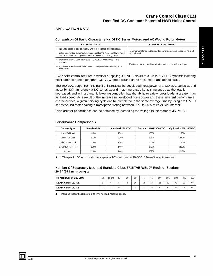
Crane Control Class 6121Rectified DC Constant Potential HWR Hoist Control
7/98
CL
AS
S 6
12
1
APPLICATION DATA
HWR hoist control features a rectifier supplying 300 VDC power to a Class 6121 DC dynamic lowering hoist controller and a standard 230 VDC series wound crane hoist motor and series brake.
The 300 VDC output from the rectifier increases the developed horsepower of a 230 VDC series wound motor by 30%. Inherently, a DC series wound motor increases its hoisting speed as the load is decreased; and with a dynamic lowering controller, has the ability to safely lower loads at greater than full load speed. As a result of the increase in developed horsepower and these inherent performance characteristics, a given hoisting cycle can be completed in the same average time by using a 230 VDC series wound motor having a horsepower rating between 50% to 65% of its AC counterpart.
Even greater performance can be obtained by increasing the voltage to the motor to 360 VDC.
▲ 100% speed = AC motor synchronous speed or DC rated speed at 230 VDC. A 90% efficiency is assumed.
▲ Includes teaser field resistors to limit no load hoisting speed.
Comparison Of Basic Characteristics Of DC Series Motors And AC Wound Rotor Motors
DC Series Motor AC Wound Rotor Motor
– No Load speed is approximately two or three times full load speed.– Maximum motor speed limited to near synchronous speed for no load
and full load.– When used with a dynamic lowering controller the motor can lower rated load at a speed much greater than the rated load hoisting speed.
– Maximum motor speed increases in proportion to increase in line voltage.
– Maximum motor speed not affected by increase in line voltage.– Increased speeds result in increased horsepower without change in
motor size.
Performance Comparison ▲
Control Type Standard AC Standard 230 VDC Standard HWR 300 VDC Optional HWR 360VDC
Hoist Full Load 96% 100% 125% 155%
Lower Full Load 102% 230% 235% 240%
Hoist Empty Hook 99% 180% 250% 280%
Lower Empty Hook 100% 140% 175% 215%
Average 99% 148% 182% 212%
Number Of Separately Mounted Standard Class 6715 TAB-WELD® Resistor Sections 26.5" (673 mm) Long ▲
Horsepower @ 230 VDC 10 13-1/2 19 26 33 45 65 100 135 200 265 360
NEMA Class 162-DL 5 5 6 8 10 12 17 21 30 43 53 68
NEMA Class 172-DL 7 7 9 11 14 17 24 30 42 60 74 96
61© 1998 Square D All Rights Reserved
Crane Control Class 6121DC Mill Auxiliary Control
62
CL
AS
S 6
12
1
GENERAL INFORMATION
DC mill auxiliary controllers are recommended for use with DC series, shunt, or compound wound motors. They are frequently used on steel mill auxiliary drives such as screwdowns, tables, sideguards, shears, and similar applications. Mill auxiliary controllers can have continuous ratings as well as intermittent and they typically include one less acceleration point than crane drives.
• Mill Duty Class 7004 Type M LINE-ARC® contactors & Class 7001 Type K relays• Class 7001 Type ST-1 static acceleration timers
Five basic control types are available. The equipment supplied as standard on each of these controllers is listed below:
Reversing Plugging (RP) Control
1 Two pole fused control circuit knife switch (CSW)
1 Two pole unfused main line knife switch with padlock clip (LSW)
1 Surge suppressor for motor shunt field protection (included on panels used with shunt or compound wound motors only)
4 Type M single pole directional contactors with mechanical interlocks (1F, 2F, 1R, 2R)
3 or 4 Type M single pole acceleration contactors (including one for plugging) (1A, 2A, 3A, P)
2 or 3 Type ST-1 static acceleration timers (1AR, 2AR, 3AR)
1 Type M single pole negative line contactor (M)
1 Type KP rectifier-plugging relay (PR)
1 Undervoltage relay (UV)
2 Magnetic overload relays (one instantaneous and one inverse time) (1OL, 2OL)
Reversing Plugging Dynamic Braking (RPD) Control
Includes the same equipment as the reversing plugging (RP) controller, but with the addition of:
1 Type M single pole spring-closed dynamic braking contactor (DB)
Non-Reversing (NR) Control
1 Two pole fused control circuit knife switch (CSW)
1 Two pole unfused main line knife switch with padlock clip (LSW)
1 Surge suppressor for motor shunt field protection (included on panels used with shunt or compound wound motors only)
1 Type M single pole positive line contactor (1M)
1 Type M single pole negative line contactor (2M)
2 or 3 Type M single pole acceleration contactors (1A, 2A, 3A)
2 or 3 Type ST-1 static acceleration timers (1AR, 2AR, 3AR)
1 Undervoltage relay (UV)
2 Magnetic overload relays (one instantaneous and one inverse time) (1OL, 2OL)
Non-Reversing Dynamic Braking (NRD) Control
Includes the same equipment as the non-reversing (NR) controller, but with the addition of:1 Type M single pole spring-closed dynamic braking contactor (DB)
Consult factory for price and delivery.
© 1998 Square D All Rights Reserved 7/98
Crane Control Class 6121DC Mill Auxiliary Control
7/98
CL
AS
S 6
12
1
GENERAL INFORMATION
Reversing Non-Plugging Dynamic Braking (RNPD) Control
1 Two-pole fused control circuit knife (CSW)
1 Two-pole unfused main line knife switch with padlock clip (LSW)
1 Surge suppressor for motor shunt field protection (included on panels used with shunt orcompound wound motors only)
4 Type M single-pole directional contactors with mechanical interlocks (1F, 2F, 1R, 2R)
2 or 3 Type M single-pole acceleration contactors (including one for plugging) (1A, 2A, 3A)
2 or 3 Type ST-1 static acceleration timers (1AR, 2AR, 3AR)
1 Type M single-pole negative line contactor (M)
1 Type M single-pole spring-closed dynamic braking contactor (DB)
1 Type KE non-plugging relay (NP)
1 Undervoltage relay (UV)
2 Magnetic overload relays (one instantaneous and one inverse time) (1OL, 2OL)
Duplex Motor Control – 2 Motors Connected In Parallel
The duplex controller consists of the equipment for a single motor controller with the exception that all contactors are double pole devices and one additional main line knife switch and two overload relays are added to the controller.
63© 1998 Square D All Rights Reserved

Crane Control Class 6121
64
CL
AS
S 6
12
1
© 1998 Square D All Rights Reserved 7/98
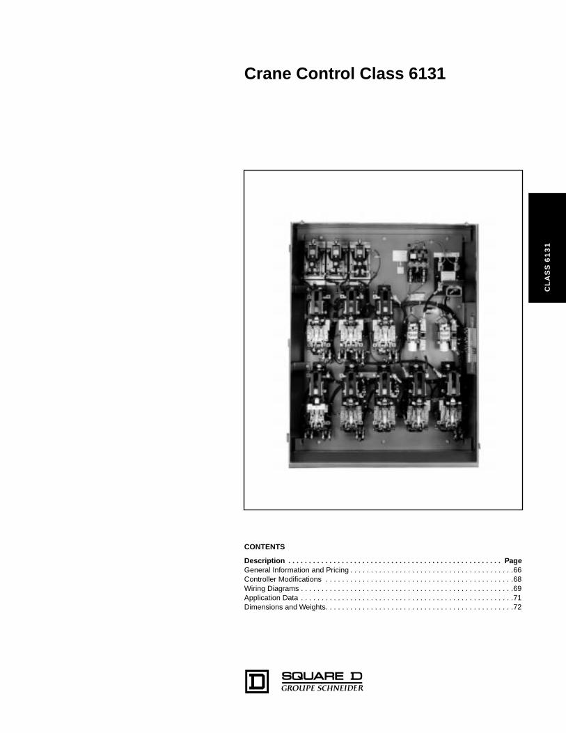
Crane Control Class 6131
CL
AS
S 6
13
1
CONTENTS
Description . . . . . . . . . . . . . . . . . . . . . . . . . . . . . . . . . . . . . . . . . . . . . . . . . . . . PageGeneral Information and Pricing . . . . . . . . . . . . . . . . . . . . . . . . . . . . . . . . . . . . . . . .66Controller Modifications . . . . . . . . . . . . . . . . . . . . . . . . . . . . . . . . . . . . . . . . . . . . . .68Wiring Diagrams . . . . . . . . . . . . . . . . . . . . . . . . . . . . . . . . . . . . . . . . . . . . . . . . . . . .69Application Data . . . . . . . . . . . . . . . . . . . . . . . . . . . . . . . . . . . . . . . . . . . . . . . . . . . .71Dimensions and Weights. . . . . . . . . . . . . . . . . . . . . . . . . . . . . . . . . . . . . . . . . . . . . .72
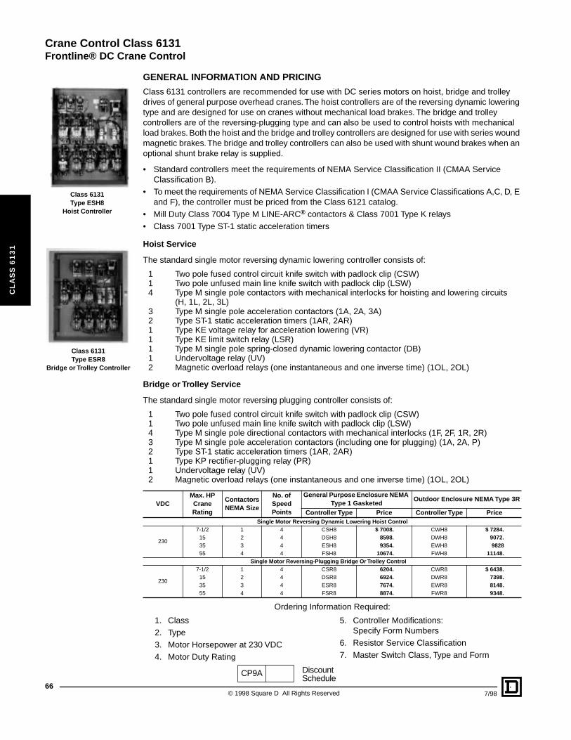
Crane Control Class 6131
Frontline® DC Crane Control
66
CL
AS
S 6
13
1
Class 6131Type ESH8
Hoist Controller
Class 6131Type ESR8
Bridge or Trolley Controller
GENERAL INFORMATION AND PRICING
Class 6131 controllers are recommended for use with DC series motors on hoist, bridge and trolley drives of general purpose overhead cranes. The hoist controllers are of the reversing dynamic lowering type and are designed for use on cranes without mechanical load brakes. The bridge and trolley controllers are of the reversing-plugging type and can also be used to control hoists with mechanical load brakes. Both the hoist and the bridge and trolley controllers are designed for use with series wound magnetic brakes. The bridge and trolley controllers can also be used with shunt wound brakes when an optional shunt brake relay is supplied.
• Standard controllers meet the requirements of NEMA Service Classification II (CMAA Service Classification B).
• To meet the requirements of NEMA Service Classification I (CMAA Service Classifications A,C, D, E and F), the controller must be priced from the Class 6121 catalog.
• Mill Duty Class 7004 Type M LINE-ARC® contactors & Class 7001 Type K relays• Class 7001 Type ST-1 static acceleration timers
Hoist Service
The standard single motor reversing dynamic lowering controller consists of:
1 Two pole fused control circuit knife switch with padlock clip (CSW)1 Two pole unfused main line knife switch with padlock clip (LSW)4 Type M single pole contactors with mechanical interlocks for hoisting and lowering circuits
(H, 1L, 2L, 3L)3 Type M single pole acceleration contactors (1A, 2A, 3A)2 Type ST-1 static acceleration timers (1AR, 2AR)1 Type KE voltage relay for acceleration lowering (VR)1 Type KE limit switch relay (LSR)1 Type M single pole spring-closed dynamic lowering contactor (DB)1 Undervoltage relay (UV)2 Magnetic overload relays (one instantaneous and one inverse time) (1OL, 2OL)
Bridge or Trolley Service
The standard single motor reversing plugging controller consists of:
1 Two pole fused control circuit knife switch with padlock clip (CSW)1 Two pole unfused main line knife switch with padlock clip (LSW)4 Type M single pole directional contactors with mechanical interlocks (1F, 2F, 1R, 2R)3 Type M single pole acceleration contactors (including one for plugging) (1A, 2A, P)2 Type ST-1 static acceleration timers (1AR, 2AR)1 Type KP rectifier-plugging relay (PR)1 Undervoltage relay (UV)2 Magnetic overload relays (one instantaneous and one inverse time) (1OL, 2OL)
Ordering Information Required:
VDCMax. HP Crane Rating
Contactors NEMA Size
No. of Speed Points
General Purpose Enclosure NEMA Type 1 Gasketed
Outdoor Enclosure NEMA Type 3R
Controller Type Price Controller Type PriceSingle Motor Reversing Dynamic Lowering Hoist Control
230
7-1/2 1 4 CSH8 $ 7008. CWH8 $ 7284.15 2 4 DSH8 8598. DWH8 9072.35 3 4 ESH8 9354. EWH8 982855 4 4 FSH8 10674. FWH8 11148.
Single Motor Reversing-Plugging Bridge Or Trolley Control
230
7-1/2 1 4 CSR8 6204. CWR8 $ 6438.15 2 4 DSR8 6924. DWR8 7398.35 3 4 ESR8 7674. EWR8 8148.55 4 4 FSR8 8874. FWR8 9348.
1. Class2. Type 3. Motor Horsepower at 230 VDC4. Motor Duty Rating
5. Controller Modifications:Specify Form Numbers
6. Resistor Service Classification7. Master Switch Class, Type and Form
CP9A DiscountSchedule
© 1998 Square D All Rights Reserv
ed 7/98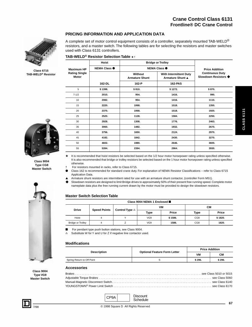
Crane Control Class 6131
Frontline® DC Crane Control
7/98
CL
AS
S 6
13
1
Class 6715TAB-WELD® Resistor
Class 9004Type CG8
Master Switch
Class 9004Type VG9
Master Switch
PRICING INFORMATION AND APPLICATION DATA
A complete set of motor control equipment consists of a controller, separately mounted TAB-WELD® resistors, and a master switch. The following tables are for selecting the resistors and master switches used with Class 6131 controllers.
★ It is recommended that hoist resistors be selected based on the 1/2 hour motor horsepower rating unless specified otherwise.It is also recommended that bridge or trolley resistors be selected based on the 1 hour motor horsepower rating unless specified otherwise.
† For resistors mounted in racks, refer to Class 6715.● Class 162 is recommended for standard crane duty. For explanation of NEMA Resistor Classifications – refer to Class 6715
Application Data.▲ Armature shunt resistors are intermittent rated for use with an armature shunt contactor, (controller Form M51).◆ Slowdown resistors are designed to limit Bridge drives to approximately 50% of their present free running speed. Complete motor
nameplate data plus the free running current drawn by the motor must be provided to design the slowdown resistors.
■ For pendant type push button stations, see Class 9004.s Substitute W for Y and U for Z if negative line contactor used.
Accessories
Brakes . . . . . . . . . . . . . . . . . . . . . . . . . . . . . . . . . . . . . . . . . . . . . . . . . . . . . . . . . . . . . . . . . . . . . . . . . . . . . . . see Class 5010 or 5015Adjustable Torque Brakes . . . . . . . . . . . . . . . . . . . . . . . . . . . . . . . . . . . . . . . . . . . . . . . . . . . . . . . . . . . . . . . . . . . . . . see Class 5060Manual-Magnetic Disconnect Switch . . . . . . . . . . . . . . . . . . . . . . . . . . . . . . . . . . . . . . . . . . . . . . . . . . . . . . . . . . . . . . see Class 6140YOUNGSTOWN® Power Limit Switch . . . . . . . . . . . . . . . . . . . . . . . . . . . . . . . . . . . . . . . . . . . . . . . . . . . . . . . . . . . . . see Class 6170
TAB-WELD® Resistor Selection Table ★ †
Maximum HP Rating Single
Motor
Hoist Bridge or Trolley
Price AdditionContinuous Duty
Slowdown Resistors ◆
NEMA Class ● NEMA Class ●
Without Armature Shunt
With Intermittent Duty Armature Shunt ▲
162-DL 162-P 162-PAS
5 $ 1398. $ 810. $ 1272. $ 870.
7-1/2 2010. 954. 1416. 990.
10 2082. 954. 1416. 1110.
15 2220. 1068. 1518. 1350.
20 2370. 1068. 1518. 1920.
25 2520. 1128. 1584. 2250.
30 2928. 1308. 1776. 2463.
35 3060. 1482. 1932. 2670.
40 3756. 1650. 2124. 2970.
45 4182. 1842. 2430. 3270.
50 4602. 1980. 2646. 3600.
55 5394. 2394. 2964. 3930.
Master Switch Selection Table
Class 9004 NEMA 1 Enclosed ■
Drive Speed Points Control Type sVM CM
Type Price Type Price
Hoist 4 Y VG9 $ 1586. CG8 $ 1820.
Bridge or Trolley 4 Z VG9 1586. CG8 1820.
Modifications
Description Optional Feature Form LetterPrice Addition
VM CM
Spring Return to Off Point S $ 296. $ 296.
CP9A DiscountSchedule
67© 1998 Square D All Rights Reserved
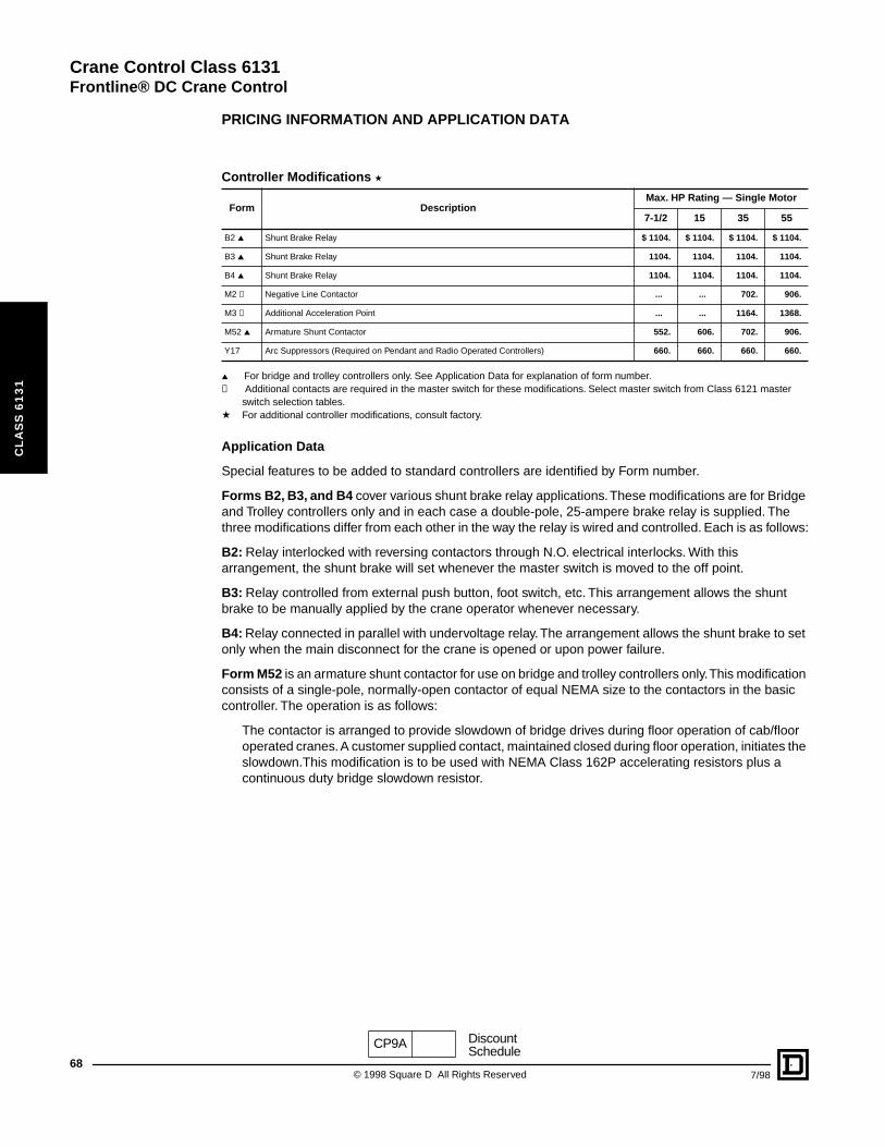
Crane Control Class 6131
Frontline® DC Crane Control
68
CL
AS
S 6
13
1
PRICING INFORMATION AND APPLICATION DATA
▲ For bridge and trolley controllers only. See Application Data for explanation of form number.✝ Additional contacts are required in the master switch for these modifications. Select master switch from Class 6121 master
switch selection tables.a For additional controller modifications, consult factory.
Application Data
Special features to be added to standard controllers are identified by Form number.
Forms B2, B3, and B4 cover various shunt brake relay applications. These modifications are for Bridge and Trolley controllers only and in each case a double-pole, 25-ampere brake relay is supplied. The three modifications differ from each other in the way the relay is wired and controlled. Each is as follows:
B2: Relay interlocked with reversing contactors through N.O. electrical interlocks. With this arrangement, the shunt brake will set whenever the master switch is moved to the off point.
B3: Relay controlled from external push button, foot switch, etc. This arrangement allows the shunt brake to be manually applied by the crane operator whenever necessary.
B4: Relay connected in parallel with undervoltage relay. The arrangement allows the shunt brake to set only when the main disconnect for the crane is opened or upon power failure.
Form M52 is an armature shunt contactor for use on bridge and trolley controllers only. This modification consists of a single-pole, normally-open contactor of equal NEMA size to the contactors in the basic controller. The operation is as follows:
The contactor is arranged to provide slowdown of bridge drives during floor operation of cab/floor operated cranes. A customer supplied contact, maintained closed during floor operation, initiates the slowdown.This modification is to be used with NEMA Class 162P accelerating resistors plus a continuous duty bridge slowdown resistor.
Controller Modifications a
Form DescriptionMax. HP Rating — Single Motor
7-1/2 15 35 55
B2 ▲ Shunt Brake Relay $ 1104. $ 1104. $ 1104. $ 1104.
B3 ▲ Shunt Brake Relay 1104. 1104. 1104. 1104.
B4 ▲ Shunt Brake Relay 1104. 1104. 1104. 1104.
M2 ✝ Negative Line Contactor ... ... 702. 906.
M3 ✝ Additional Acceleration Point ... ... 1164. 1368.
M52 ▲ Armature Shunt Contactor 552. 606. 702. 906.
Y17 Arc Suppressors (Required on Pendant and Radio Operated Controllers) 660. 660. 660. 660.
CP9A DiscountSchedule
© 1998 Square D All Rights Reserved 7/98
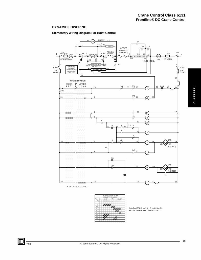
Crane Control Class 6131
Frontline® DC Crane Control
7/98
CL
AS
S 6
13
1
DYNAMIC LOWERING
Elementary Wiring Diagram For Hoist Control
(IF USED)R12 R13TEASER RES
1A
DB
H
H
2L 3L
DB
1L
1L
VR
H
3L
DB
R8R5
R7R6
+ -
UV
VR
1OL 2OL
2L
Y1 Y4
LSR 25
LSW LSW
1L
3A
R4
R3 R2
12
3L3L
TWO SHOESRECOMMENDED
SEE SERVICEBULLETIN
SERIESFIELD
ARMA1 A2
DYN BRK'G RES
DB
B
SERIESBRAKE(S)(IF USED)
2L
1A2A
FUSE15A
CSW CSW
15AFUSE
1OL
INST
1L
H2OL
ITE
VR
1A
H
DB
3L
2L
2A
1L
UV
3A
ACCEL RESISTOR
Y5
LS LS
42 43LSR
PU 55V
LS RESY3LS
LSY6 Y2
(1) (3)
2AR
(0.6 SEC)
(1) (3)
1AR
(0.6 SEC)
26
2A
3A39 40
OFF12 234 3 41
DEVICE
CONTACTOR SEQUENCEX=POWER TIPS CLOSED
HOIST LOWER
H
DB
1L
2L
3L
1A
2A
3A
CONTACTORS 1A & 1L, 3L & H, H & 2L,ARE MECHANICALLY INTERLOCKED.
8
5
2821
11
20
2 3LOWER
F
S2
1 20
2
6
27
30
31
22 23
28
24 26
31 33
33
32
34
7 35 36
37
12 26
X = CONTACT CLOSED
20
20
R1R5
1 4HOIST O
F
MASTER SWITCH
S1 R9
41
26
CAUTION
+ -2FU
(IF USED)
1FU
(IF USED)
4 3 2 1
69© 1998 Square D All Rights Reserved
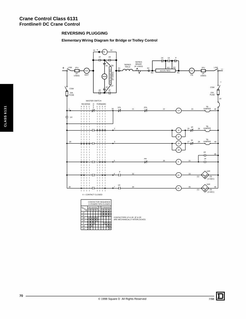
Crane Control Class 6131
Frontline® DC Crane Control
70
CL
AS
S 6
13
1
REVERSING PLUGGING
Elementary Wiring Diagram for Bridge or Trolley Control
AR
M S
HU
NT
RE
S(I
F U
SE
D)
OFF1234 1 2 3 4
CONTACTOR SEQUENCEX=POWER TIPS CLOSED
PR
1AR
(3)(1)(.6 SEC)
2AR
(3)(1)(.6 SEC)
+
1R
2F2R
1F P2A 1A
1FU
(IFUSED)
2FU
(IFUSED)ITE
REVERSE FORWARD
1F2F1R2RP
1A2A
5
6
7
3
2
4 3 2 1 1 2 3 4REVERSE FORWARD
FFO
MASTER SWITCH
20
PR30
UV23
1R25 26
40
40
1F
2F
1R
2F28
2R
P
1A
2A
1OL 2OL21 22
P32
1A34
27
31
33
35
40
40
1R
2F
24
15A.FUSE
CSW
15A.FUSE
CSW
–
1
UV
20
20TB
JUMPER
TBJUMPER
TBJUMPER
X = CONTACT CLOSED
+ LSW
2OL
INST
1OL
41 42
A1
A2
S1
SERIESFIELD
SERIESBRAKE
(IF USED)S2
R4
R7
R6
ARM
R1ACCEL RES
LSW –R2R3
CONTACTORS 1F & 1R, 2F & 2RARE MECHANICALLY INTERLOCKED.
DEVICE
© 1998 Square D All Rights Reserved 7/98
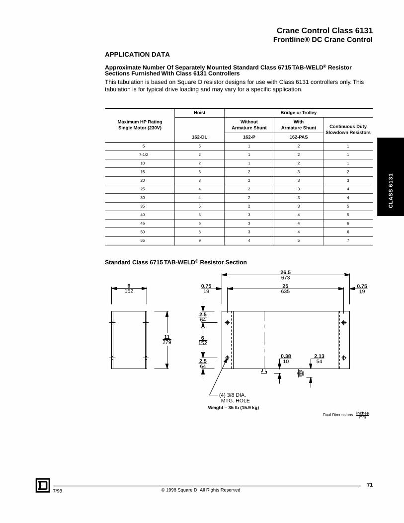
Crane Control Class 6131
Frontline® DC Crane Control
7/98
CL
AS
S 6
13
1
APPLICATION DATA
Approximate Number Of Separately Mounted Standard Class 6715 TAB-WELD® Resistor Sections Furnished With Class 6131 ControllersThis tabulation is based on Square D resistor designs for use with Class 6131 controllers only. This tabulation is for typical drive loading and may vary for a specific application.
Standard Class 6715 TAB-WELD® Resistor Section
Maximum HP Rating Single Motor (230V)
Hoist Bridge or Trolley
Without Armature Shunt
With Armature Shunt Continuous Duty
Slowdown Resistors162-DL 162-P 162-PAS
5 5 1 2 1
7-1/2 2 1 2 1
10 2 1 2 1
15 3 2 3 2
20 3 2 3 3
25 4 2 3 4
30 4 2 3 4
35 5 2 3 5
40 6 3 4 5
45 6 3 4 6
50 8 3 4 6
55 9 4 5 7
6152
6152
25635
0.7519
0.7519
26.5673
2.564
2.564
2.1354
0.3810
(4) 3/8 DIA.MTG. HOLE
11279
Weight – 35 lb (15.9 kg)
Dual Dimensions inchesmm
71© 1998 Square D All Rights Reserved
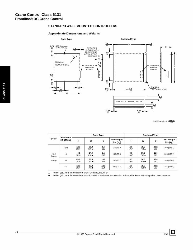
Crane Control Class 6131
Frontline® DC Crane Control
72
CL
AS
S 6
13
1
STANDARD WALL MOUNTED CONTROLLERS
Approximate Dimensions and Weights
▲ Add 6" (152 mm) for controllers with Forms B2, B3, or B4.● Add 6" (152 mm) for controllers with Form M3 – Additional Acceleration Point and/or Form M2 – Negative Line Contactor.
DriveMaximum HP (230V)
Open Type Enclosed Type
H W CNet Weight
lbs (kg)H W D
Net Weight lbs (kg)
Hoist Bridge
or Trolley
7-1/240.01016
24.0610 ▲
8.5216
150 (68.0)42
106730.0
762 ▲15.0381
300 (136.1)
1540.01016
24.0610 ▲
8.5216
150 (68.0)42
106730.0
762 ▲15.0381
300 (136.1)
3540.01016
30.0762 ●
10.0254
200 (90.7)42
106736.0
914 ●15.0381
385 (174.6)
5540.01016
30.0762 ●
10.0254
200 (90.7)42
106736.0
914 ●15.0381
385 (174.6)
Dual Dimensions inchesmm
0.7519
0.7519
3.076
3.076 0.75
19
1.5038
1.5038
3.076
3.076
3.076
1.538
12.0305
W
1.846
1.538
1.538
3.076
C
H
D
W
W+
– +
INCOMING LINE
.468 DIA.
0.625 DIA.16
TERMINAL
MTG. HOLE
MTG. HOLE
REQUIRED CLEARANCE TO NEAREST
CONDUCTING SURFACE
CONTROL TERMINAL
BOARD
CONTROL TERMINAL
BOARD
SPACE FOR CONDUIT ENTRY
Open Type Enclosed Type
© 1998 Square D All Rights Reserved 7/98
Crane Control Class 6140
CL
AS
S 6
14
0
CONTENTS
Description . . . . . . . . . . . . . . . . . . . . . . . . . . . . . . . . . . . . . . . . . . . . . . . . . . . . PagePricing and Ordering Information . . . . . . . . . . . . . . . . . . . . . . . . . . . . . . . . . . . . . . .74Application Data . . . . . . . . . . . . . . . . . . . . . . . . . . . . . . . . . . . . . . . . . . . . . . . . . . . .75Wiring Diagram . . . . . . . . . . . . . . . . . . . . . . . . . . . . . . . . . . . . . . . . . . . . . . . . . . . . .76

Crane Control Class 6140
Frontline® Manual-Magnetic Disconnect Switches for DC Cranes
74
CL
AS
S 6
14
0
Class 6140 Type MHS11 Manual and Magnetic
Disconnect Switch
PRICING AND ORDERING INFORMATION
The manual-magnetic disconnect switch is used for protecting electrical crane circuits except lifting magnet circuits. It meets OSHA requirements for a crane disconnect switch.
• Contactors operated remotely or by handle on the enclosure• Flange mounted operator permits operation only with door closed
The standard disconnect switch consists of:
2 Class 7004 Type M, Form Y781 (with silver-faced power contact tips), SPNO contactors. The contactors are mechanically tied. One normally open and one normally closed electrical interlocks are included for indicating lights.
1 Two pole, fused, control circuit knife switch.1 Class 9999 Type AI-1 arc suppressor.1 Set of incoming and outgoing power lugs.1 Class 7001 relay only on NEMA Sizes 6, 8, and on 1600 and 2700 A devices.
▲ Consult factory for price and delivery.a Not a NEMA size/rating.
■ Customer must specify fuse rating in amperes. If not specified, fuse will be sized for maximum current rating of switch.
Pilot Devices
For separately mounted pilot devices refer to Class 9001.
Ordering Information Required:
1. Class2. Type 3. Controller Modifications: Specify Form Numbers
Class 6440 Manual-Magnetic Disconnect Switches for AC cranes are also available. Consult factory.
VDCContactors NEMA Size
Continuous Ampere Rating
General Purpose Enclosure NEMA Type 1 Gasketed
Industrial Enclosure NEMA Type 12 Outdoor Enclosure NEMA Type 3R
Type Price Type Price
230
4 150 MFS11 $ 4173. MFA11 $ 4656.
5 300 MGS11 5168. MGA11 5649.
5Aa 400 MGAS11 5943. MGAA11 6496.
6 600 MHS11 7155. MHA11 7643.
8 1350 MKS11 14304. MKA11 15281.
... 1600 ▲ ▲ ▲ ▲
... 2700 ▲ ▲ ▲ ▲
Controller Modifications
Form Description
Price
Continuous Ampere Rating
150 300 400 600 1350
F30 ■ 2 Main-line, DC-rated power fuses $ 1950. $ 2610. $ 2715. $ 4160. $ 4625.
A3 “On-Off” pushbutton 204. 204. 204. 204. 204.
P1 Red “On” pilot light 204. 204. 204. 204. 204.
P2 Green “Off” pilot light 204. 204. 204. 204. 204.
CP9A DiscountSchedule
© 1998 Square D All Rights Reserved 7/98
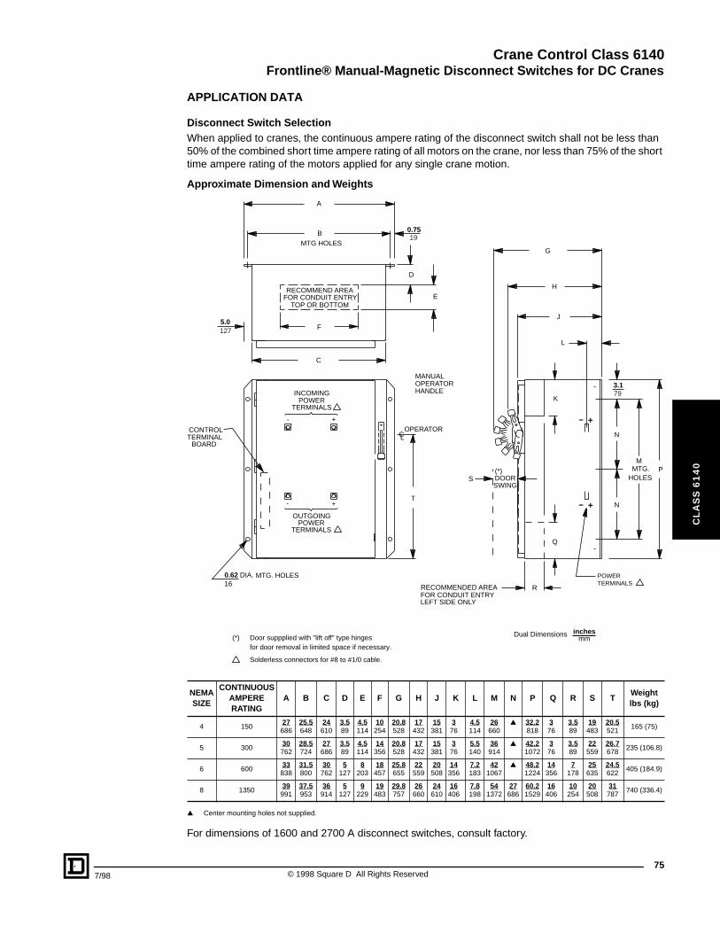
Crane Control Class 6140
Frontline® Manual-Magnetic Disconnect Switches for DC Cranes
7/98
CL
AS
S 6
14
0
APPLICATION DATA
Disconnect Switch SelectionWhen applied to cranes, the continuous ampere rating of the disconnect switch shall not be less than 50% of the combined short time ampere rating of all motors on the crane, nor less than 75% of the short time ampere rating of the motors applied for any single crane motion.
Approximate Dimension and Weights
▲ Center mounting holes not supplied.
For dimensions of 1600 and 2700 A disconnect switches, consult factory.
NEMA SIZE
CONTINUOUS AMPERE RATING
A B C D E F G H J K L M N P Q R S TWeightlbs (kg)
4 15027686
25.5648
24610
3.589
4.5114
10254
20.8528
17432
15381
376
4.5114
26660
▲ 32.2818
376
3.589
19483
20.5521
165 (75)
5 30030
76228.5724
27686
3.589
4.5114
14356
20.8528
17432
15381
376
5.5140
36914
▲ 42.21072
376
3.589
22559
26.7678
235 (106.8)
6 60033838
31.5800
30762
5127
8203
18457
25.8655
22559
20508
14356
7.2183
421067
▲ 48.21224
14356
7178
25635
24.5622
405 (184.9)
8 135039
99137.5953
36914
5127
9229
19483
29.8757
26660
24610
16406
7.8198
541372
27686
60.21529
16406
10254
20508
31787
740 (336.4)
Door suppplied with "lift off" type hingesfor door removal in limited space if necessary.
Solderless connectors for #8 to #1/0 cable.
CONTROL
MANUAL
POWER
TERMINAL
OPERATOR
TERMINALS
BOARD
HANDLE
BMTG HOLES
A
0.75
E
D
T
C
F5.0
G
J
H
S
K
Q
R
3.1
P
L
N
N
MTG.HOLES
M
0.62 DIA.16
OPERATOR
RECOMMENDED AREAFOR CONDUIT ENTRYLEFT SIDE ONLY
DOOR(*)
(*)
SWING
+
+
-
-
MTG. HOLES
C
POWERTERMINALS
OUTGOING
INCOMING
POWERTERMINALS
FOR CONDUIT ENTRYTOP OR BOTTOM
RECOMMEND AREA
L
- +
- +
19
79
127
Dual Dimensions inchesmm
75© 1998 Square D All Rights Reserved
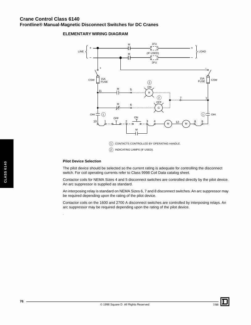
Crane Control Class 6140
Frontline® Manual-Magnetic Disconnect Switches for DC Cranes
76
CL
AS
S 6
14
0
ELEMENTARY WIRING DIAGRAM
Pilot Device Selection
The pilot device should be selected so the current rating is adequate for controlling the disconnect switch. For coil operating currents refer to Class 9998 Coil Data catalog sheet.
Contactor coils for NEMA Sizes 4 and 5 disconnect switches are controlled directly by the pilot device. An arc suppressor is supplied as standard.
An interposing relay is standard on NEMA Sizes 6, 7 and 8 disconnect switches. An arc suppressor may be required depending upon the rating of the pilot device.
Contactor coils on the 1600 and 2700 A disconnect switches are controlled by interposing relays. An arc suppressor may be required depending upon the rating of the pilot device.
.
CONTACTS CONTROLLED BY OPERATING HANDLE.
INDICATING LAMPS (IF USED).
1
1 1
2
2
2
M
M
M
OHIOHI
M M
OFF ON
(IF USED)
2FU
1FU
8 9
7 7
11
–+
LOADLINE
M
M
CSW CSW15A 15AFUSE FUSE
121
ON
OFF
5
6
R
G
210 43
++
––
© 1998 Square D All Rights Reserved 7/98
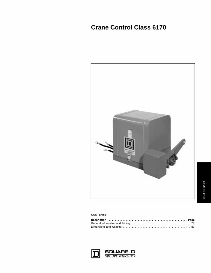
Crane Control Class 6170
CL
AS
S 6
17
0
CONTENTS
Description . . . . . . . . . . . . . . . . . . . . . . . . . . . . . . . . . . . . . . . . . . . . . . . . . . . . PageGeneral Information and Pricing . . . . . . . . . . . . . . . . . . . . . . . . . . . . . . . . . . . . . . . .78Dimensions and Weights. . . . . . . . . . . . . . . . . . . . . . . . . . . . . . . . . . . . . . . . . . . . . .81
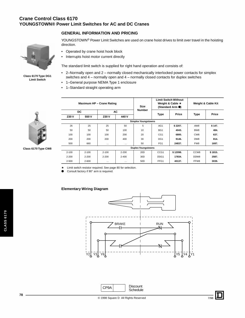
Crane Control Class 6170
YOUNGSTOWN® Power Limit Switches for AC and DC Cranes
78
CL
AS
S 6
17
0
Class 6170 Type DG1 Limit Switch
Class 6170 Type CW8
GENERAL INFORMATION AND PRICING
YOUNGSTOWN® Power Limit Switches are used on crane hoist drives to limit over travel in the hoisting direction.
• Operated by crane hoist hook block• Interrupts hoist motor current directly
The standard limit switch is supplied for right hand operation and consists of:
• 2–Normally open and 2 – normally closed mechanically interlocked power contacts for simplex switches and 4 – normally open and 4 – normally closed contacts for duplex switches
• 1–General purpose NEMA Type 1 enclosure• 1–Standard straight operating arm
a Limit switch resistor required. See page 80 for selection.● Consult factory if 90° arm is required.
Elementary Wiring Diagram
Maximum HP – Crane RatingSize
Number
Limit Switch Without Weight & Cable a(Standard Arm ●)
Weight & Cable Kit
DC ACType Price Type Price
230 V 550 V 230 V 440 V
Simplex Youngstowns
26 25 25 50 5 AG1 $ 2207. AW8 $ 147.
50 50 50 100 10 BG1 4043. BW8 484.
100 100 100 200 20 CG1 6800. CW8 637.
200 200 200 400 30 DG1 9146. DW8 814.
500 660 ... ... 50 FG1 24837. FW8 1697.
Duplex Youngstowns
2-100 2-100 2-100 2-200 20D CCG1 $ 12098. CCW8 $ 1815.
2-200 2-200 2-200 2-400 30D DDG1 17834. DDW8 2587.
2-500 2-600 ... ... 50D FFG1 40137. FFW8 3039.
RUNBRAKE
Y2 Y1Y6 Y5Y3 Y4
CP9A DiscountSchedule
© 1998 Square D All Rights Reserved 7/98
Crane Control Class 6170
YOUNGSTOWN® Power Limit Switches for AC and DC Cranes
7/98
CL
AS
S 6
17
0
PRICING INFORMATION AND APPLICATION DATA
Right Hand Operation
The limit switch is arranged for right hand operation when the reset weight and cable are on the right side (when facing the operating arm).
Standard Operating Arm
The standard operating arm is used when the weight and cable can be suspended beneath the limit switch.
Control Circuit Interlocks
Control circuit interlocks are provided on the power limit switch by an externally mounted control circuit limit switch which is operated by the power limit switch operating arm.
For a Type AG limit switch, a Class 9007 Type B limit switch is used.
For Types BG through FFG limit switches, a Class 9007 Type FT limit switch is used.
▲ Only available on Size 5, 10, and 20 Power Limit Switches.a Consult factory for additional modifications.
Ordering Information Required:
1. Class and Type of limit switch.2. Modifications of limit switch: specify form number.3. Class and type of weight and cable kit, if required.4. Class and type of resistor (see next page).
Modifications a
Form Description Price
L Operating arm arranged for left hand operation No Charge
X110 Control Circuit Interlock: 1 N.O. and 1 N.C. Contact $ 302.
X111 ▲Control Circuit Interlock: 1 N.O. and 1 N.C. Contact set to operate prior to main power contacts(required for drive applications)
500.
CP9A DiscountSchedule
79© 1998 Square D All Rights Reserved
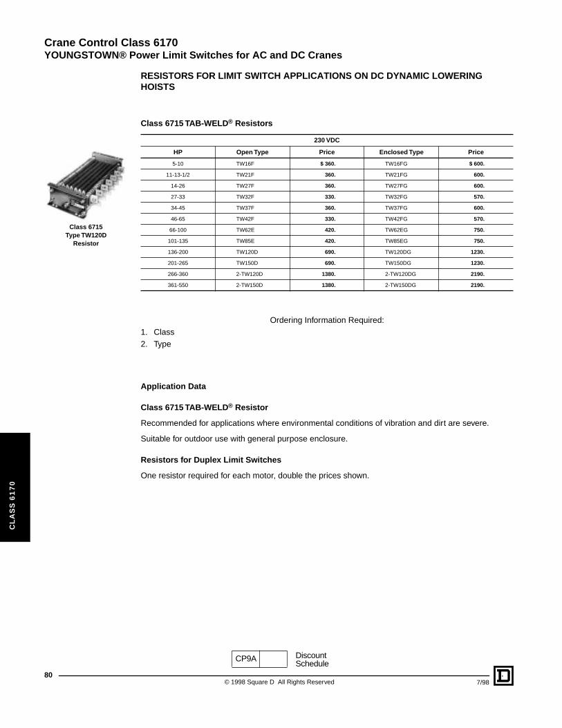
Crane Control Class 6170
YOUNGSTOWN® Power Limit Switches for AC and DC Cranes
80
CL
AS
S 6
17
0
Class 6715Type TW120D
Resistor
RESISTORS FOR LIMIT SWITCH APPLICATIONS ON DC DYNAMIC LOWERING HOISTS
Ordering Information Required:1. Class2. Type
Application Data
Class 6715 TAB-WELD® Resistor
Recommended for applications where environmental conditions of vibration and dirt are severe.
Suitable for outdoor use with general purpose enclosure.
Resistors for Duplex Limit Switches
One resistor required for each motor, double the prices shown.
Class 6715 TAB-WELD® Resistors
230 VDC
HP Open Type Price Enclosed Type Price
5-10 TW16F $ 360. TW16FG $ 600.
11-13-1/2 TW21F 360. TW21FG 600.
14-26 TW27F 360. TW27FG 600.
27-33 TW32F 330. TW32FG 570.
34-45 TW37F 360. TW37FG 600.
46-65 TW42F 330. TW42FG 570.
66-100 TW62E 420. TW62EG 750.
101-135 TW85E 420. TW85EG 750.
136-200 TW120D 690. TW120DG 1230.
201-265 TW150D 690. TW150DG 1230.
266-360 2-TW120D 1380. 2-TW120DG 2190.
361-550 2-TW150D 1380. 2-TW150DG 2190.
CP9A DiscountSchedule
© 1998 Square D All Rights Reserved 7/98
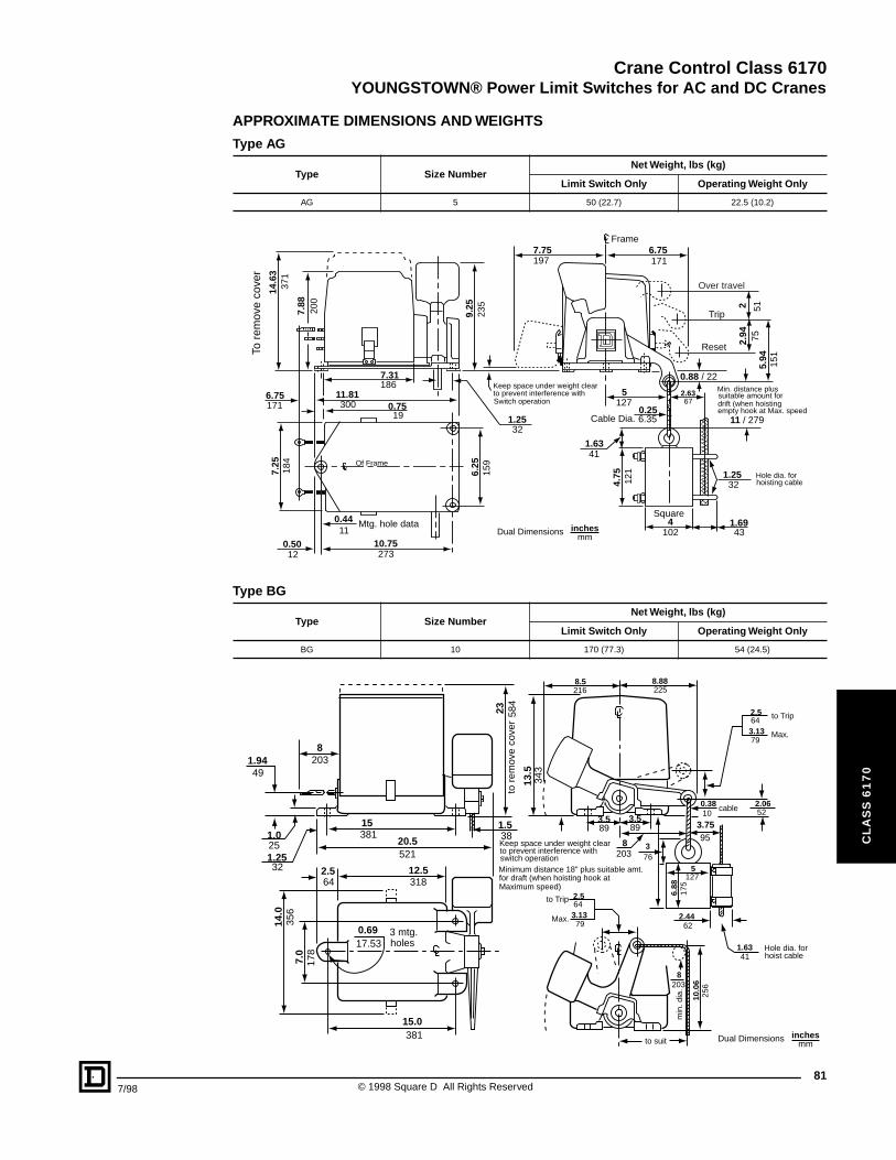
Crane Control Class 6170
YOUNGSTOWN® Power Limit Switches for AC and DC Cranes
7/98
CL
AS
S 6
17
0
APPROXIMATE DIMENSIONS AND WEIGHTS
Type AG
Type Size NumberNet Weight, lbs (kg)
Limit Switch Only Operating Weight Only
AG 5 50 (22.7) 22.5 (10.2)
Type BG
Type Size NumberNet Weight, lbs (kg)
Limit Switch Only Operating Weight Only
BG 10 170 (77.3) 54 (24.5)
Keep space under weight clearto prevent interference withSwitch operation
Min. distance plussuitable amount fordrift (when hoistingempty hook at Max. speed
To r
emov
e co
ver
14.6
337
1
7.88
200
6.75171
7.31186
11.81300 0.75
19
Of Frame
0.4411
Mtg. hole data
7.25
184
10.75273
0.5012
6.25
159
1.2532
9.25
235
7.75197
6.75171
Frame
Over travel
Trip
Reset
0.256.35Cable Dia.
5127
2 51
2.94 75
5.94
151
0.88 / 22
11 / 279
1.2532
Hole dia. forhoisting cable
2.6367
1.6943
4102
Square
4.75
121
1.6341
Dual Dimensions inchesmm
32
23 584
to r
emov
e co
ver
8203
13.5
343
1.9449
1.25
381.5
1.025
15381
20.5521
2.564
12.5318
14.0
356
7.0
178
15.0381
0.6917.53
3 mtg.holes
3.589
3.589
8203
3.7595
Keep space under weight clearto prevent interference withswitch operationMinimum distance 18" plus suitable amt.for draft (when hoisting hook atMaximum speed)
2.5643.1379
to Trip
Max.
5127
6.88
175
376
8.5 8.88216 225
2.5643.1379
to Trip
Max.
2.0652
0.3810
cable
2.4462
1.6341
Hole dia. forhoist cable
10.0
625
6
8203
min
. dia
.
to suit Dual Dimensions inchesmm
81© 1998 Square D All Rights Reserved
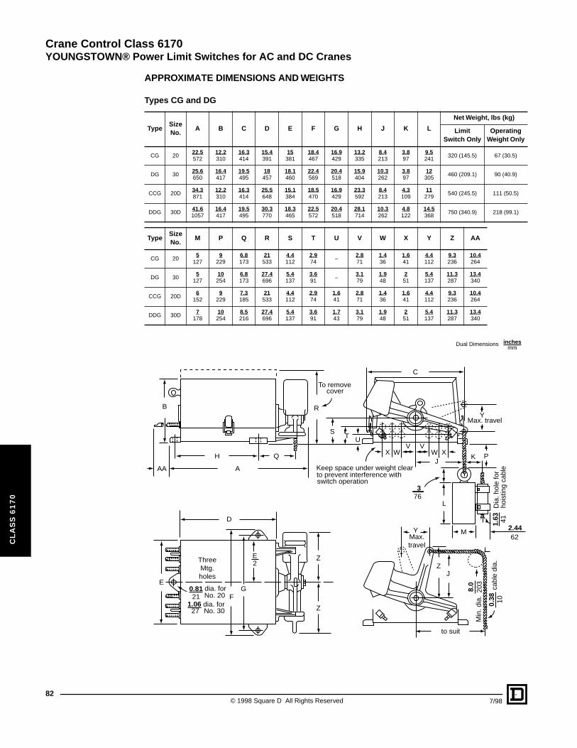
Crane Control Class 6170
YOUNGSTOWN® Power Limit Switches for AC and DC Cranes
82
CL
AS
S 6
17
0
APPROXIMATE DIMENSIONS AND WEIGHTS
Types CG and DG
TypeSize No.
A B C D E F G H J K L
Net Weight, lbs (kg)
Limit Switch Only
Operating Weight Only
CG 2022.5572
12.2310
16.3414
15.4391
15381
18.4467
16.9429
13.2335
8.4213
3.897
9.5241
320 (145.5) 67 (30.5)
DG 3025.6650
16.4417
19.5495
18457
18.1460
22.4569
20.4518
15.9404
10.3262
3.897
12305
460 (209.1) 90 (40.9)
CCG 20D34.3871
12.2310
16.3414
25.5648
15.1384
18.5470
16.9429
23.3592
8.4213
4.3109
11279
540 (245.5) 111 (50.5)
DDG 30D41.61057
16.4417
19.5495
30.3770
18.3465
22.5572
20.4518
28.1714
10.3262
4.8122
14.5368
750 (340.9) 218 (99.1)
TypeSize No.
M P Q R S T U V W X Y Z AA
CG 205
1279
2296.8173
21533
4.4112
2.974
–2.871
1.436
1.641
4.4112
9.3236
10.4264
DG 305
12710254
6.8173
27.4696
5.4137
3.691
–3.179
1.948
251
5.4137
11.3287
13.4340
CCG 20D6
1529
2297.3185
21533
4.4112
2.974
1.641
2.871
1.436
1.641
4.4112
9.3236
10.4264
DDG 30D7
17810254
8.5216
27.4696
5.4137
3.691
1.743
3.179
1.948
251
5.4137
11.3287
13.4340
YMax.travel
ZJ
M
to suit
8.0
203
Min
. dia
.
0.38 10
cabl
e di
a.
2.4462
1.63 41
Dia
. hol
e fo
rho
istin
g ca
ble
L
376
JK
XWV V
WX
U
Max. travel
C
R
To removecover
Q
ST
Keep space under weight clearto prevent interference withswitch operation
B
AA
H
A
D
E2
EG0.81
21
27
dia. forNo. 20
1.06 dia. forNo. 30
ThreeMtg.holes
Z
Z
P
F
Y
Dual Dimensions inchesmm
© 1998 Square D All Rights Reserved 7/98

Crane Control Class 6170
YOUNGSTOWN® Power Limit Switches for AC and DC Cranes
7/98
CL
AS
S 6
17
0
APPROXIMATE DIMENSIONS AND WEIGHTS Type FG
Type Size No. A B C D
Net Weight, lbs (kg)
Limit Switch Only
Operating Weight Only
FG 5042.41077
36914
24610
14.8376
1550 (704.5) 265 (120.5)
FFG 50D66.41687
601524
481219
29.5749
2350 (1068.2) 530 (240.9)
D
A
40.88
42.881038
1089
for simplex
for duplex
3/8 x 2 Busbar --- 9/16 dia. hole6 for simplex* 12 for duplex
to suit
15.1
338
4
9.75
248
3.7595
376
12.5 12.5318 318
9.75 9.75248 248
376
376
376
3.38 8.5
3.38
86
86
2164.5114
B
C25
.13
638
32 / 813To remove coverand arc chutes
6.25159
4.13105
20.31516
13.3
834
0M
ax. t
rave
l
Keep space under weight clearto prevent interference withswitch operation 8
203
376
5.25133
21533
2.4462
13.38340
Max. travel
20.3
151
6
10254
min. dia.
0.5
13di
a. c
able
1.63 41
dia.
hol
e fo
rho
istin
g ca
ble
4.13105
36.38
38.38924
975
for simplex
for duplex
30 762
34.8
888
632
.88
835
24610
for duplex only
1.0627
dia. mtg. holes
4 for simplex6 for duplex
Dual Dimensions inchesmm
83© 1998 Square D All Rights Reserved
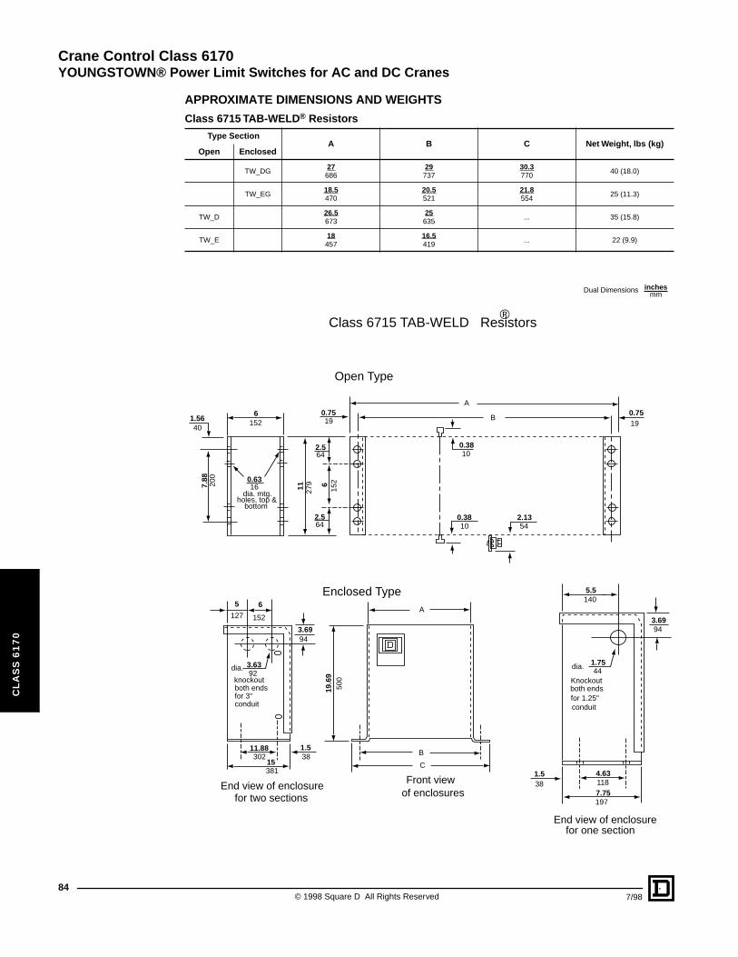
Crane Control Class 6170YOUNGSTOWN® Power Limit Switches for AC and DC Cranes
84
CL
AS
S 6
17
0
APPROXIMATE DIMENSIONS AND WEIGHTS
Class 6715 TAB-WELD® Resistors
Type SectionA B C Net Weight, lbs (kg)
Open Enclosed
TW_DG27
68629737
30.3770
40 (18.0)
TW_EG18.5470
20.5521
21.8554
25 (11.3)
TW_D26.5673
25635
... 35 (15.8)
TW_E18457
16.5419
... 22 (9.9)
Dual Dimensions inchesmm
6152
1.5640
7.88
200
0.7519
0.6316
dia. mtg.holes, top &
bottom
11 279 6
152
2.5
2.5
64
64
A
B
0.38
0.38
10
102.1354
5
127
6
152
0.7519
3.6994
19.6
950
0
A
B
C
3.6392
dia.
knockoutboth endsfor 3"conduit
End view of enclosurefor two sections
11.88302
15381
1.538
Front viewof enclosures
5.5140
3.6994
1.7544
dia.
Knockoutboth endsfor 1.25"conduit
1.538
4.631187.75197
End view of enclosurefor one section
Enclosed Type
Open Type
Class 6715 TAB-WELD Resistors®
© 1998 Square D All Rights Reserved 7/98
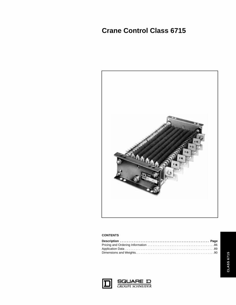
Crane Control Class 6715
71
5
CONTENTS
Description . . . . . . . . . . . . . . . . . . . . . . . . . . . . . . . . . . . . . . . . . . . . . . . . . . . . PagePricing and Ordering Information . . . . . . . . . . . . . . . . . . . . . . . . . . . . . . . . . . . . . . .86Application Data . . . . . . . . . . . . . . . . . . . . . . . . . . . . . . . . . . . . . . . . . . . . . . . . . . . .89Dimensions and Weights. . . . . . . . . . . . . . . . . . . . . . . . . . . . . . . . . . . . . . . . . . . . . .90
CL
AS
S 6
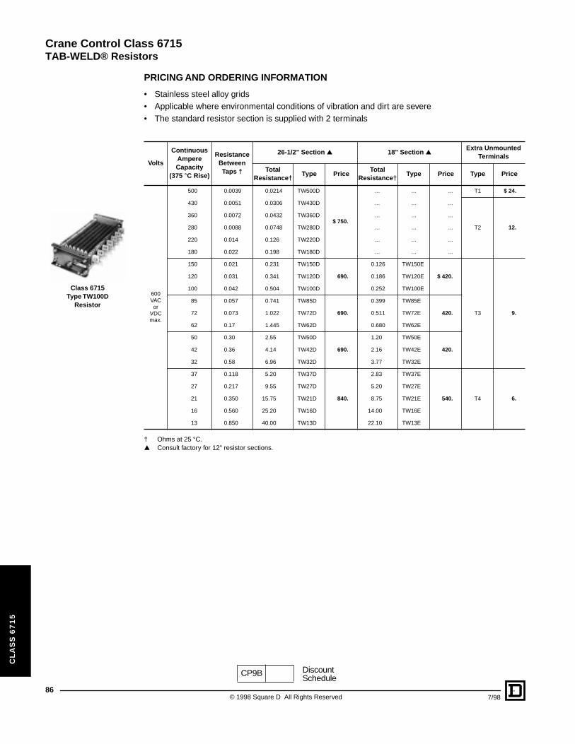
Crane Control Class 6715
TAB-WELD® Resistors
86
CL
AS
S 6
71
5
Class 6715 Type TW100D
Resistor
PRICING AND ORDERING INFORMATION
• Stainless steel alloy grids• Applicable where environmental conditions of vibration and dirt are severe• The standard resistor section is supplied with 2 terminals
† Ohms at 25 °C.▲ Consult factory for 12" resistor sections.
Volts
Continuous Ampere Capacity
(375 °C Rise)
Resistance Between Taps †
26-1/2" Section ▲ 18" Section ▲Extra Unmounted
Terminals
Total Resistance†
Type PriceTotal
Resistance†Type Price Type Price
600VAC or
VDCmax.
500 0.0039 0.0214 TW500D
$ 750.
... ... ... T1 $ 24.
430 0.0051 0.0306 TW430D ... ... ...
T2 12.
360 0.0072 0.0432 TW360D ... ... ...
280 0.0088 0.0748 TW280D ... ... ...
220 0.014 0.126 TW220D ... ... ...
180 0.022 0.198 TW180D ... ... ...
150 0.021 0.231 TW150D
690.
0.126 TW150E
$ 420.
T3 9.
120 0.031 0.341 TW120D 0.186 TW120E
100 0.042 0.504 TW100D 0.252 TW100E
85 0.057 0.741 TW85D
690.
0.399 TW85E
420.72 0.073 1.022 TW72D 0.511 TW72E
62 0.17 1.445 TW62D 0.680 TW62E
50 0.30 2.55 TW50D
690.
1.20 TW50E
420.42 0.36 4.14 TW42D 2.16 TW42E
32 0.58 6.96 TW32D 3.77 TW32E
37 0.118 5.20 TW37D
840.
2.83 TW37E
540. T4 6.
27 0.217 9.55 TW27D 5.20 TW27E
21 0.350 15.75 TW21D 8.75 TW21E
16 0.560 25.20 TW16D 14.00 TW16E
13 0.850 40.00 TW13D 22.10 TW13E
CP9B DiscountSchedule
© 1998 Square D All Rights Reserved 7/98
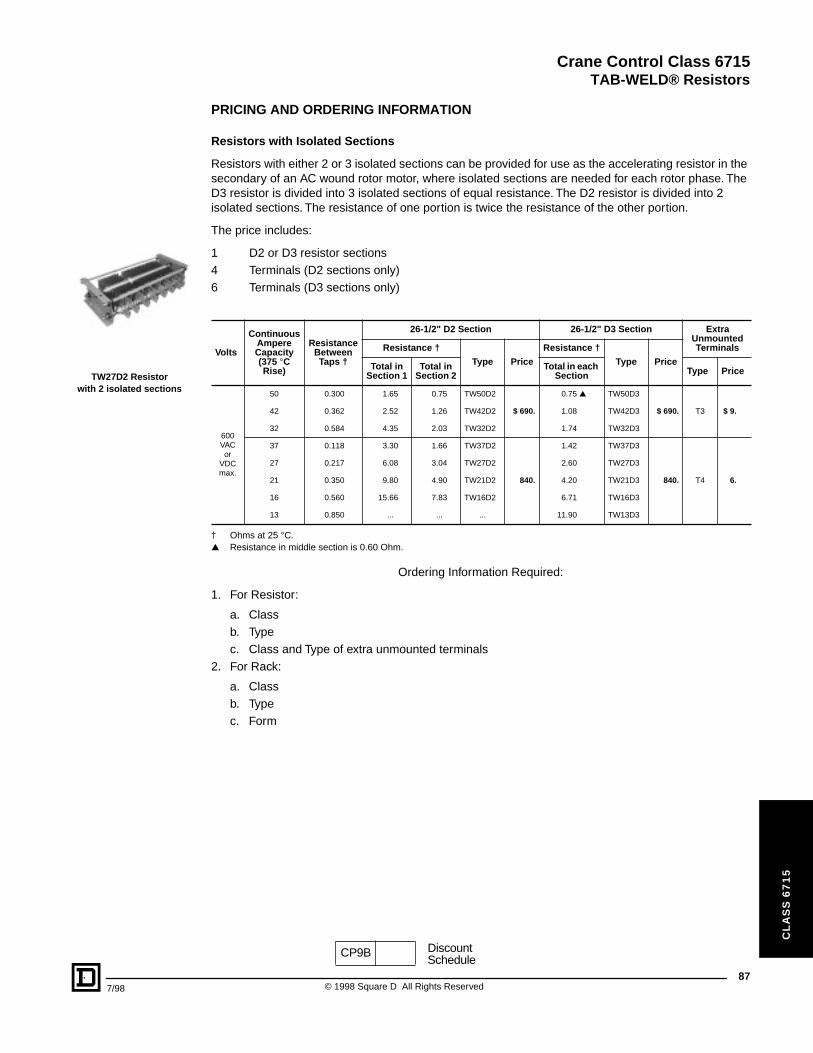
Crane Control Class 6715
TAB-WELD® Resistors
7/98
CL
AS
S 6
71
5
TW27D2 Resistor with 2 isolated sections
PRICING AND ORDERING INFORMATION
Resistors with Isolated Sections
Resistors with either 2 or 3 isolated sections can be provided for use as the accelerating resistor in the secondary of an AC wound rotor motor, where isolated sections are needed for each rotor phase. The D3 resistor is divided into 3 isolated sections of equal resistance. The D2 resistor is divided into 2 isolated sections. The resistance of one portion is twice the resistance of the other portion.
The price includes:
1 D2 or D3 resistor sections4 Terminals (D2 sections only)6 Terminals (D3 sections only)
† Ohms at 25 °C.▲ Resistance in middle section is 0.60 Ohm.
Ordering Information Required:
1. For Resistor:
a. Classb. Typec. Class and Type of extra unmounted terminals
2. For Rack:
a. Classb. Typec. Form
Volts
Continuous Ampere Capacity (375 °C Rise)
Resistance Between Taps †
26-1/2" D2 Section 26-1/2" D3 Section Extra Unmounted TerminalsResistance †
Type Price
Resistance †
Type PriceTotal in Section 1
Total in Section 2
Total in each Section Type Price
600VAC or
VDCmax.
50 0.300 1.65 0.75 TW50D2
$ 690.
0.75 ▲ TW50D3
$ 690. T3 $ 9.42 0.362 2.52 1.26 TW42D2 1.08 TW42D3
32 0.584 4.35 2.03 TW32D2 1.74 TW32D3
37 0.118 3.30 1.66 TW37D2
840.
1.42 TW37D3
840. T4 6.
27 0.217 6.08 3.04 TW27D2 2.60 TW27D3
21 0.350 9.80 4.90 TW21D2 4.20 TW21D3
16 0.560 15.66 7.83 TW16D2 6.71 TW16D3
13 0.850 ... ... ... 11.90 TW13D3
CP9B DiscountSchedule
87© 1998 Square D All Rights Reserved
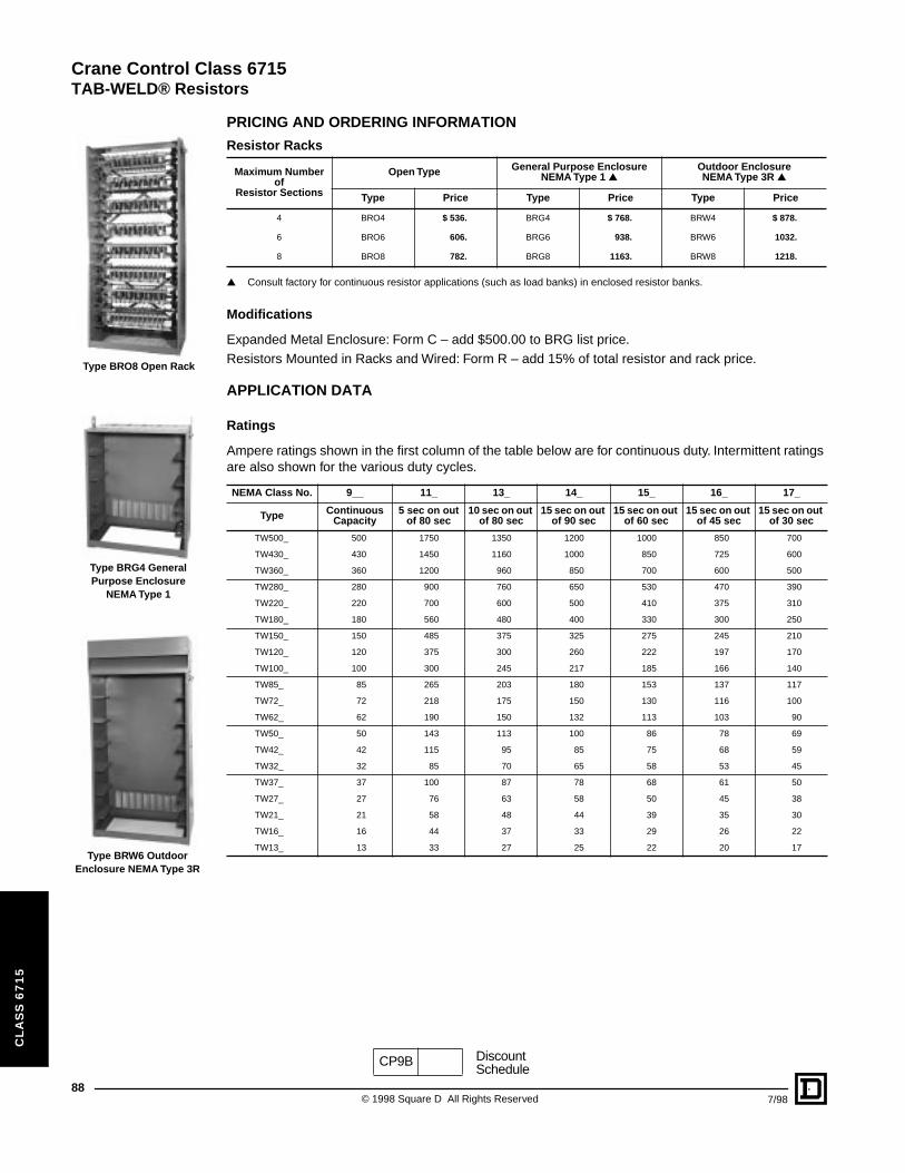
Crane Control Class 6715
TAB-WELD® Resistors
88
CL
AS
S 6
71
5
Type BRO8 Open Rack
Type BRG4 General Purpose Enclosure
NEMA Type 1
Type BRW6 Outdoor Enclosure NEMA Type 3R
PRICING AND ORDERING INFORMATION
▲ Consult factory for continuous resistor applications (such as load banks) in enclosed resistor banks.
Modifications
Expanded Metal Enclosure: Form C – add $500.00 to BRG list price.Resistors Mounted in Racks and Wired: Form R – add 15% of total resistor and rack price.
APPLICATION DATA
Ratings
Ampere ratings shown in the first column of the table below are for continuous duty. Intermittent ratings are also shown for the various duty cycles.
Resistor Racks
Maximum Number of
Resistor Sections
Open Type General Purpose Enclosure NEMA Type 1 ▲
Outdoor EnclosureNEMA Type 3R ▲
Type Price Type Price Type Price
4 BRO4 $ 536. BRG4 $ 768. BRW4 $ 878.
6 BRO6 606. BRG6 938. BRW6 1032.
8 BRO8 782. BRG8 1163. BRW8 1218.
NEMA Class No. 9__ 11_ 13_ 14_ 15_ 16_ 17_
Type Continuous Capacity
5 sec on out of 80 sec
10 sec on out of 80 sec
15 sec on out of 90 sec
15 sec on out of 60 sec
15 sec on out of 45 sec
15 sec on out of 30 sec
TW500_ 500 1750 1350 1200 1000 850 700
TW430_ 430 1450 1160 1000 850 725 600
TW360_ 360 1200 960 850 700 600 500
TW280_ 280 900 760 650 530 470 390
TW220_ 220 700 600 500 410 375 310
TW180_ 180 560 480 400 330 300 250
TW150_ 150 485 375 325 275 245 210
TW120_ 120 375 300 260 222 197 170
TW100_ 100 300 245 217 185 166 140
TW85_ 85 265 203 180 153 137 117
TW72_ 72 218 175 150 130 116 100
TW62_ 62 190 150 132 113 103 90
TW50_ 50 143 113 100 86 78 69
TW42_ 42 115 95 85 75 68 59
TW32_ 32 85 70 65 58 53 45
TW37_ 37 100 87 78 68 61 50
TW27_ 27 76 63 58 50 45 38
TW21_ 21 58 48 44 39 35 30
TW16_ 16 44 37 33 29 26 22
TW13_ 13 33 27 25 22 20 17
CP9B DiscountSchedule
© 1998 Square D All Rights Reserved 7/98
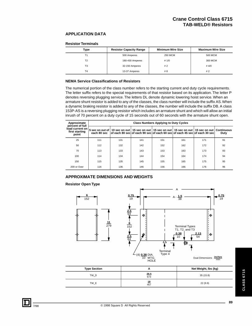
Crane Control Class 6715
TAB-WELD® Resistors
7/98
CL
AS
S 6
71
5
APPLICATION DATA
Resistor Terminals
NEMA Service Classifications of Resistors
The numerical portion of the class number refers to the starting current and duty cycle requirements. The letter suffix refers to the special requirements of that resistor based on its application. The letter P denotes reversing plugging service. The letters DL denote dynamic lowering hoist service. When an armature shunt resistor is added to any of the classes, the class number will include the suffix AS. When a dynamic braking resistor is added to any of the classes, the number will include the suffix DB. A class 153P-AS is a reversing plugging resistor which includes an armature shunt and which will allow an initial inrush of 70 percent on a duty cycle of 15 seconds out of 60 seconds with the armature shunt open.
APPROXIMATE DIMENSIONS AND WEIGHTS
Resistor Open Type
Type Resistor Capacity Range Minimum Wire Size Maximum Wire Size
T1 500 Amperes 250 MCM 500 MCM
T2 180-430 Amperes # 1/0 300 MCM
T3 32-150 Amperes # 2 # 4/0
T4 13-37 Amperes # 8 # 2
Approximate percent of full
load current on first starting
point
Class Numbers Applying to Duty Cycles
5 sec on out of each 80 sec
10 sec on out of each 80 sec
15 sec on out of each 90 sec
15 sec on out of each 60 sec
15 sec on out of each 45 sec
15 sec on out of each 30 sec
Continuous Duty
25 111 131 141 151 161 171 91
50 112 132 142 152 162 172 92
70 113 133 143 153 163 173 93
100 114 134 144 154 164 174 94
150 115 135 145 155 165 175 95
200 or Over 116 136 146 156 166 176 96
Type Section A Net Weight, lbs (kg)
TW_D26.5673
35 (15.8)
TW_E18457
22 (9.9)
6152
279
A - 0.75
A
2.1354
0.3810
(4) 0.38 DIA.MTG.HOLE
11
1526
64
190.7519
2.5
381.5
64
10
2.5
Terminal TypesT1, T2, and T3
Terminal Type 4
Dual Dimensions inchesmm
89© 1998 Square D All Rights Reserved
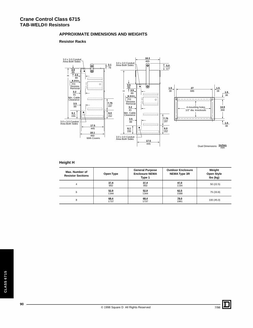
Crane Control Class 6715
TAB-WELD® Resistors
90
CL
AS
S 6
71
5
APPROXIMATE DIMENSIONS AND WEIGHTS
Resistor Racks
Height H
Max. Number of Resistor Sections
Open TypeGeneral Purpose Enclosure NEMA
Type 1
Outdoor Enclosure NEMA Type 3R
WeightOpen Style
lbs (kg)
437.4950
37.4950
47.01194
50 (22.5)
652.91344
52.91344
62.51588
75 (33.8)
868.41737
68.41737
78.01981
100 (45.0)
1.538
5.0127
1.538 1.5
38
1.538
14.5368
27686
18.3465
17.5445
4-mounting holes1/2" dia. knockouts
H
8.3211
3.589
3.589
3.281
3.589
6.1155
Min.
ResistorRemoval
Min. CableClearance
3.0 x 3.0 ConduitArea Both Sides
3.0 x 3.0 ConduitArea Both Sides
6.0152
7.75197
3.179
18.1460
With Covers
17.5445
H
8.3211
3.589
3.589
3.281
3.589
6.1155
Min.
ResistorRemoval
Min. CableClearance
3.0 x 3.0 ConduitArea Both Sides
3.0 x 3.0 ConduitArea Both Sides
6.0152
7.75197
Dual Dimensions inchesmm
© 1998 Square D All Rights Reserved 7/98
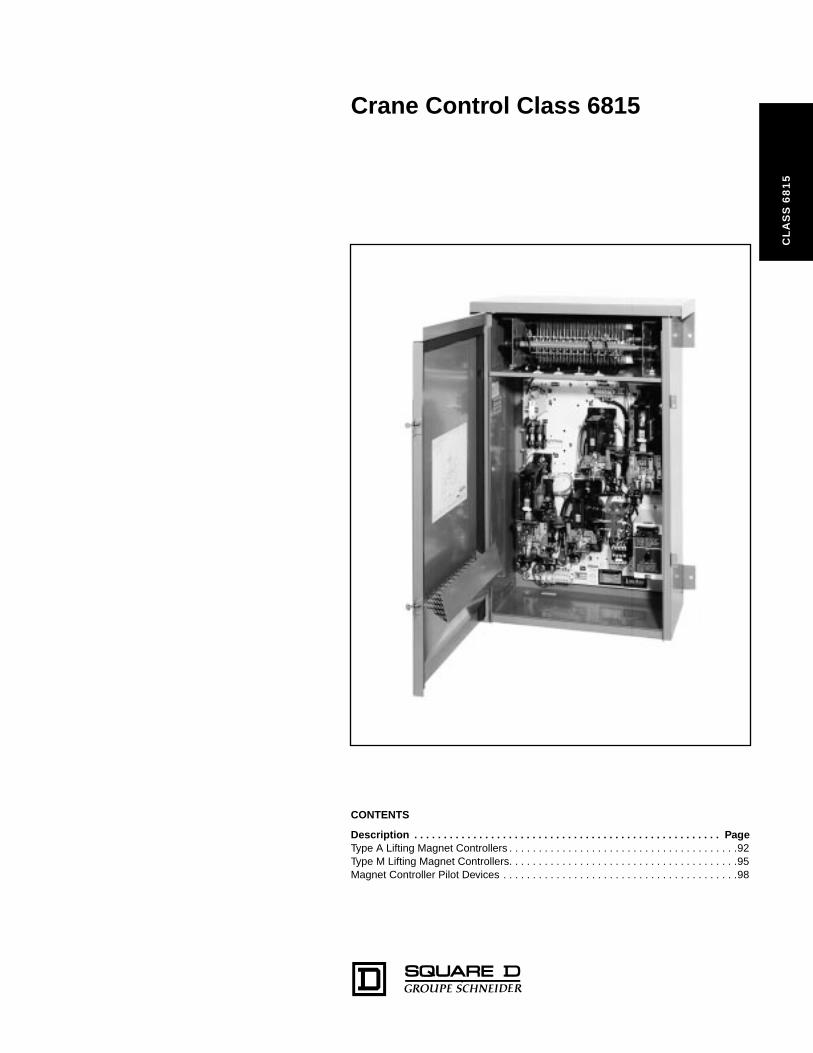
Crane Control Class 6815
CL
AS
S 6
81
5
CONTENTS
Description . . . . . . . . . . . . . . . . . . . . . . . . . . . . . . . . . . . . . . . . . . . . . . . . . . . . PageType A Lifting Magnet Controllers . . . . . . . . . . . . . . . . . . . . . . . . . . . . . . . . . . . . . . .92Type M Lifting Magnet Controllers. . . . . . . . . . . . . . . . . . . . . . . . . . . . . . . . . . . . . . .95Magnet Controller Pilot Devices . . . . . . . . . . . . . . . . . . . . . . . . . . . . . . . . . . . . . . . .98
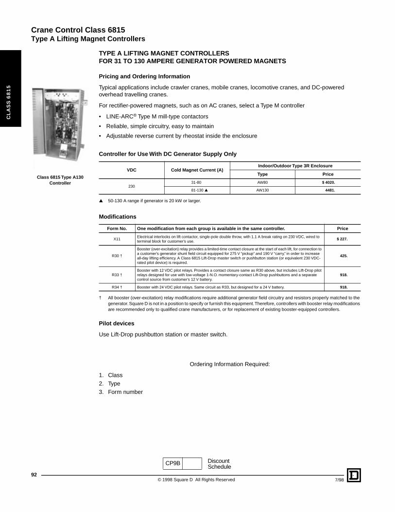
Crane Control Class 6815
Type A Lifting Magnet Controllers
92
CL
AS
S 6
81
5
Class 6815 Type A130 Controller
TYPE A LIFTING MAGNET CONTROLLERS FOR 31 TO 130 AMPERE GENERATOR POWERED MAGNETS
Pricing and Ordering Information
Typical applications include crawler cranes, mobile cranes, locomotive cranes, and DC-powered overhead travelling cranes.
For rectifier-powered magnets, such as on AC cranes, select a Type M controller
• LINE-ARC® Type M mill-type contactors
• Reliable, simple circuitry, easy to maintain
• Adjustable reverse current by rheostat inside the enclosure
▲ 50-130 A range if generator is 20 kW or larger.
† All booster (over-excitation) relay modifications require additional generator field circuitry and resistors properly matched to the generator. Square D is not in a position to specify or furnish this equipment. Therefore, controllers with booster relay modifications are recommended only to qualified crane manufacturers, or for replacement of existing booster-equipped controllers.
Pilot devices
Use Lift-Drop pushbutton station or master switch.
Ordering Information Required:
1. Class2. Type3. Form number
Controller for Use With DC Generator Supply Only
VDC Cold Magnet Current (A)Indoor/Outdoor Type 3R Enclosure
Type Price
23031-80 AW80 $ 4020.
81-130 ▲ AW130 4481.
Modifications
Form No. One modification from each group is available in the same controller. Price
X11Electrical interlocks on lift contactor, single-pole double throw, with 1.1 A break rating on 230 VDC, wired to terminal block for customer’s use.
$ 227.
R30 †
Booster (over-excitation) relay provides a limited-time contact closure at the start of each lift, for connection to a customer’s generator shunt field circuit equipped for 275 V “pickup” and 190 V “carry,” in order to increase all-day lifting efficiency. A Class 6815 Lift-Drop master switch or pushbutton station (or equivalent 230 VDC-rated pilot device) is required.
425.
R33 †Booster with 12 VDC pilot relays. Provides a contact closure same as R30 above, but includes Lift-Drop pilot relays designed for use with low-voltage 1-N.O. momentary-contact Lift-Drop pushbuttons and a separate control source from customer’s 12 V battery.
918.
R34 † Booster with 24 VDC pilot relays. Same circuit as R33, but designed for a 24 V battery. 918.
CP9B DiscountSchedule
© 1998 Square D All Rights Reserved 7/98
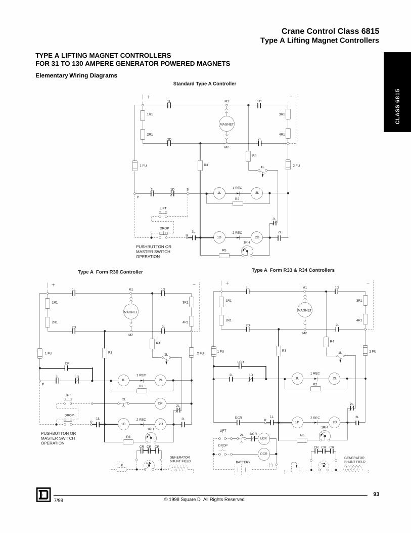
Crane Control Class 6815
Type A Lifting Magnet Controllers
CL
AS
S 6
81
5
TYPE A LIFTING MAGNET CONTROLLERSFOR 31 TO 130 AMPERE GENERATOR POWERED MAGNETS
Elementary Wiring Diagrams
MAGNET
1L 2L
2L
1D 2D
1 REC
2 REC
2L
2L
R2
1RH
R5
1LR
2L
LCR
DCR
DCR
1D
R3
2D
1R1
2R1
1 FU 2 FU
1L M1 1D
M2
2L
3R1
4R1
R4
1L
Type A Form R33 & R34 Controllers
CR CR CR
GENERATOR SHUNT FIELD
LIFT
DROP
LCR
DCR
BATTERY
MAGNET
1L 2L
2LCR
1D 2D
1 REC
2 REC
2L
2L
R2
1RH
R5
1LR
DROP
LIFT
P
2L
CR
1D
R3
2D
1R1
2R1
1 FU 2 FU
1L M1 1D
M2
2L
3R1
4R1
R4
1L
PUSHBUTTON OR MASTER SWITCHOPERATION
Type A Form R30 Controller
CR CR CR
GENERATOR SHUNT FIELD
MAGNET
1L 2L
1D 2D
1 REC
2 REC
2L
2L
R2
1RH
R5
1LR
DROP
LIFT
P
2L 1D S
R3
2D
1R1
2R1
1 FU 2 FU
1L M1 1D
M2
2L
3R1
4R1
R4
1L
PUSHBUTTON OR MASTER SWITCHOPERATION
Standard Type A Controller
937/98 © 1998 Square D All Rights Reserved
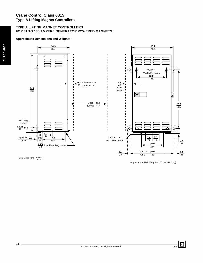
Crane Control Class 6815
Type A Lifting Magnet Controllers
CL
AS
S 6
81
5
TYPE A LIFTING MAGNET CONTROLLERSFOR 31 TO 130 AMPERE GENERATOR POWERED MAGNETS
Approximate Dimensions and Weights
10.0254
0.820
1.846
14.3363
16.8427
2.563
0.26
0.62516 Dia.
0.46812 Dia. Floor Mtg. Holes
Clearance toLift Door Off
DoorSwing
DoorSwing
Type 3ROnly
19.0483
10.0254
Type 3ROnly
Approximate Net Weight – 150 lbs (67.5 kg)
Wall Mtg.Holes
7.0178
18.2462
12.9328
TYPE 1Wall Mtg. Holes
3.076
3.076
1.025
1.025
1.641
26.2665
3 KnockoutsFor 1.50 Conduit
34.2869
Dual Dimensions inchesmm
© 1998 Square D All Rights Reserved94
7/98
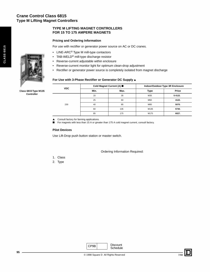
Crane Control Class 6815
Type M Lifting Magnet Controllers
95
CL
AS
S 6
81
5
Class 6815 Type M135 Controller
TYPE M LIFTING MAGNET CONTROLLERSFOR 15 TO 175 AMPERE MAGNETS
Pricing and Ordering Information
For use with rectifier or generator power source on AC or DC cranes.
• LINE-ARC® Type M mill-type contactors• TAB-WELD® mill-type discharge resistor• Reverse-current adjustable within enclosure• Reverse-current monitor light for optimum clean-drop adjustment• Rectifier or generator power source is completely isolated from magnet discharge
▲ Consult factory for fanning applications.■ For magnets with less than 15 A or greater than 175 A cold magnet current, consult factory.
Pilot Devices
Use Lift-Drop push button station or master switch.
Ordering Information Required:
1. Class2. Type
For Use with 3-Phase Rectifier or Generator DC Supply ▲
VDCCold Magnet Current (A) ■ Indoor/Outdoor Type 3R Enclosure
Min. Max. Type Price
230
15 35 M35 $ 4122.
25 60 M60 4122.
40 85 M85 5070.
60 135 M135 5730.
85 175 M175 6027.
CP9B DiscountSchedule
© 1998 Square D All Rights Reserved 7/98
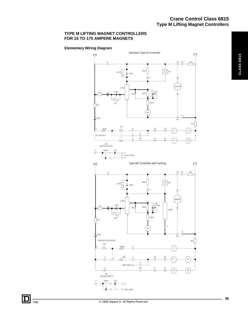
Crane Control Class 6815
Type M Lifting Magnet Controllers
7/98
CL
AS
S 6
81
5
TYPE M LIFTING MAGNET CONTROLLERSFOR 15 TO 175 AMPERE MAGNETS
Elementary Wiring Diagram
(–)(+)
MAGNET
1L
IL
ILM
2 SP
2 REC
2 RES
1 RES
M1 2D 2FU
2L
M2
DR
DR
3 RES
1 RH4RES1D1FU
3FU
3 REC
P
P
DROP
LIFT
T
S
R
T (NOT USED)
S
R
1L
1L
2L
1L 2L
1D 2D
2D1D
DR
4FU
P.B. STATION
– OR –MASTER SWITCH
DROP LIFT
1 SP1 REC
Standard Type M Controller
(–)(+)
MAGNET
1L
IL
ILM
2 SP
2 REC
2 RES
1 RES
M1 2D 2FU
2L
M2
DR
DR
3 RES
1 RH1 K 50W
4RES1D1FU
3FU
3 REC
P
P
DROP
FAN
(NOT USED)
LIFT
T
SF
F F
F
F
F RES
(NOT USED)
S
1L
1L
2L
1L 2L
1D 2D
2D1D
DR
4FUPUSH BUTTON STATION
– OR –MASTER SWITCH
DROP LIFT
1 SP1 REC
Type MF Controller with Fanning
96© 1998 Square D All Rights Reserved
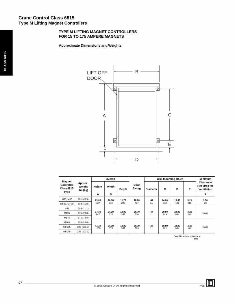
Crane Control Class 6815
Type M Lifting Magnet Controllers
97
CL
AS
S 6
81
5
TYPE M LIFTING MAGNET CONTROLLERSFOR 15 TO 175 AMPERE MAGNETS
Approximate Dimensions and Weights
Magnet Controller Class 6815
Type
Approx. Weightlbs (kg)
Overall
Door Swing
Wall Mounting Holes Minimum Clearance
Required for Ventilation
Height WidthDepth Diameter C D E
A B F
M35, M60 101 (45.5) 29.00737
20.38518
11.73298
18.00457
.4411
24.00610
19.38492
3.2182
1.5038MF35, MF60 104 (46.8)
M85 158 (71.1)37.30947
24.20615
13.90352
20.70526
.4411
29.50749
23.00584
3.2081
NoneM135 175 (78.8)
M175 175 (78.8)
MF85 208 (93.6)43.301100
24.20615
13.90352
20.70526
.4411
35.50902
23.00584
3.2081
NoneMF135 225 (101.3)
MF175 225 (101.3)
Dual Dimensions: inchesmm
LIFT-OFFDOOR
B
A C
E
D
F
© 1998 Square D All Rights Reserved 7/98
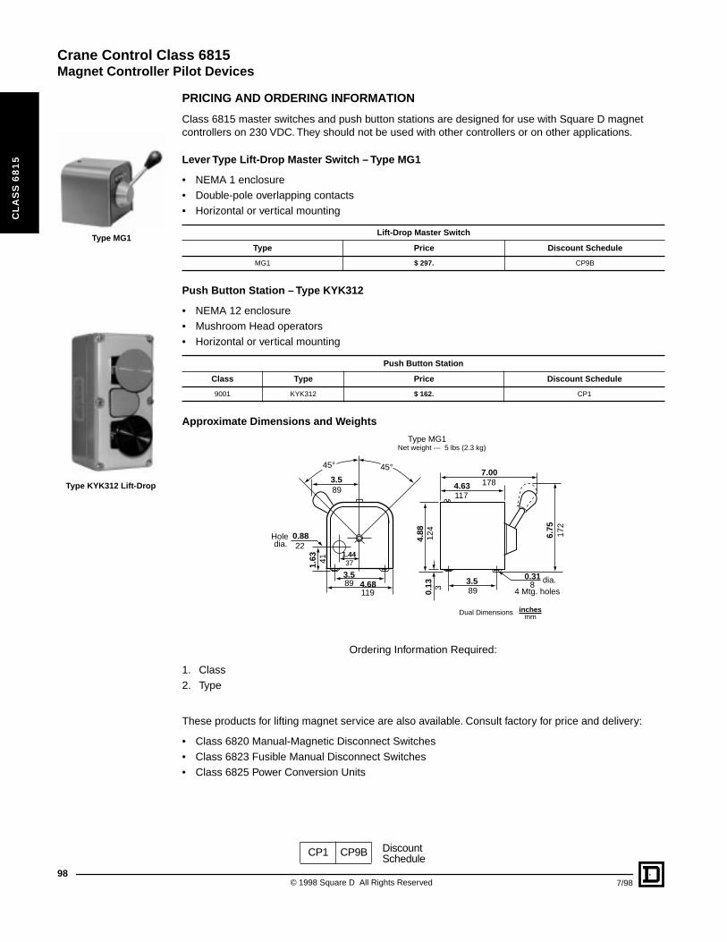
Crane Control Class 6815
Magnet Controller Pilot Devices
98
CL
AS
S 6
81
5
Type MG1
Type KYK312 Lift-Drop
PRICING AND ORDERING INFORMATION
Class 6815 master switches and push button stations are designed for use with Square D magnet controllers on 230 VDC. They should not be used with other controllers or on other applications.
Lever Type Lift-Drop Master Switch – Type MG1
• NEMA 1 enclosure• Double-pole overlapping contacts• Horizontal or vertical mounting
Push Button Station – Type KYK312
• NEMA 12 enclosure• Mushroom Head operators• Horizontal or vertical mounting
Approximate Dimensions and Weights
Ordering Information Required:
1. Class2. Type
These products for lifting magnet service are also available. Consult factory for price and delivery:
• Class 6820 Manual-Magnetic Disconnect Switches• Class 6823 Fusible Manual Disconnect Switches• Class 6825 Power Conversion Units
Lift-Drop Master Switch
Type Price Discount Schedule
MG1 $ 297. CP9B
Push Button Station
Class Type Price Discount Schedule
9001 KYK312 $ 162. CP1
1.4437
7.001784.63
117
6.75
172
4.88
124
3.589
0.318 dia.
4 Mtg. holes0.13 3
45° 45°3.589
0.8822
Holedia.
1.63 41
3.589 4.68
119
Type MG1Net weight --- 5 lbs (2.3 kg)
Dual Dimensions inchesmm
CP1 CP9B DiscountSchedule
© 1998 Square D All Rights Reserved 7/98
Crane Control Class 7001
CL
AS
S 7
00
1
CONTENTS
Description . . . . . . . . . . . . . . . . . . . . . . . . . . . . . . . . . . . . . . . . . . . . . . . . . . . . PageType K DC Relays . . . . . . . . . . . . . . . . . . . . . . . . . . . . . . . . . . . . . . . . . . . . . . . . . .100Type ST DC Static Timer. . . . . . . . . . . . . . . . . . . . . . . . . . . . . . . . . . . . . . . . . . . . .106Type SSI DC Acceleration Module . . . . . . . . . . . . . . . . . . . . . . . . . . . . . . . . . . . . .107
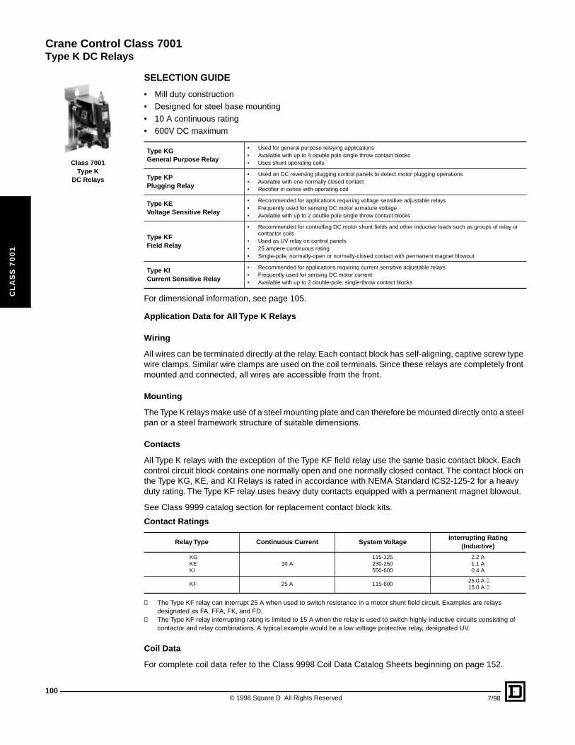
Crane Control Class 7001
Type K DC Relays
100
CL
AS
S 7
00
1
Class 7001Type K
DC Relays
SELECTION GUIDE
• Mill duty construction• Designed for steel base mounting• 10 A continuous rating• 600V DC maximum
For dimensional information, see page 105.
Application Data for All Type K Relays
Wiring
All wires can be terminated directly at the relay. Each contact block has self-aligning, captive screw type wire clamps. Similar wire clamps are used on the coil terminals. Since these relays are completely front mounted and connected, all wires are accessible from the front.
Mounting
The Type K relays make use of a steel mounting plate and can therefore be mounted directly onto a steel pan or a steel framework structure of suitable dimensions.
Contacts
All Type K relays with the exception of the Type KF field relay use the same basic contact block. Each control circuit block contains one normally open and one normally closed contact. The contact block on the Type KG, KE, and KI Relays is rated in accordance with NEMA Standard ICS2-125-2 for a heavy duty rating. The Type KF relay uses heavy duty contacts equipped with a permanent magnet blowout.
See Class 9999 catalog section for replacement contact block kits.
① The Type KF relay can interrupt 25 A when used to switch resistance in a motor shunt field circuit. Examples are relays designated as FA, FFA, FK, and FD.
➁ The Type KF relay interrupting rating is limited to 15 A when the relay is used to switch highly inductive circuits consisting of contactor and relay combinations. A typical example would be a low voltage protective relay, designated UV.
Coil Data
For complete coil data refer to the Class 9998 Coil Data Catalog Sheets beginning on page 152.
Type KGGeneral Purpose Relay
• Used for general purpose relaying applications• Available with up to 4 double pole single throw contact blocks• Uses shunt operating coils
Type KPPlugging Relay
• Used on DC reversing plugging control panels to detect motor plugging operations• Available with one normally closed contact• Rectifier in series with operating coil
Type KEVoltage Sensitive Relay
• Recommended for applications requiring voltage sensitive adjustable relays• Frequently used for sensing DC motor armature voltage• Available with up to 2 double pole single throw contact blocks
Type KFField Relay
• Recommended for controlling DC motor shunt fields and other inductive loads such as groups of relay or contactor coils
• Used as UV relay on control panels• 25 ampere continuous rating• Single-pole, normally-open or normally-closed contact with permanent magnet blowout
Type KICurrent Sensitive Relay
• Recommended for applications requiring current sensitive adjustable relays• Frequently used for sensing DC motor current• Available with up to 2 double-pole, single-throw contact blocks
Contact Ratings
Relay Type Continuous Current System VoltageInterrupting Rating
(Inductive)
KGKEKI
10 A115-125230-250550-600
2.2 A1.1 A0.4 A
KF 25 A 115-60025.0 A ①15.0 A ➁
© 1998 Square D All Rights Reserved 7/98
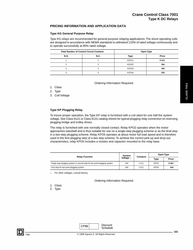
Crane Control Class 7001
Type K DC Relays
7/98
CL
AS
S 7
00
1
PRICING INFORMATION AND APPLICATION DATA
Type KG General Purpose Relay
Type KG relays are recommended for general purpose relaying applications. The shunt operating coils are designed in accordance with NEMA standards to withstand 110% of rated voltage continuously and to operate successfully at 80% rated voltage.
Ordering Information Required:1. Class2. Type3. Coil Voltage
Type KP Plugging Relay
To insure proper operation, the Type KP relay is furnished with a coil rated for one half the system voltage. See Class 6121 or Class 6131 catalog sheets for typical plugging relay connection on reversing plugging bridge and trolley drives.
The relay is furnished with one normally closed contact. Relay KPO2 operates when the motor approaches standstill and is thus suitable for use on a single-step plugging scheme or as the final step in a two-step plugging scheme. Relay KPO5 operates at about motor full load speed and is therefore used in the first plugging step of a two step scheme. To achieve the correct pick-up and drop-out characteristics, relay KPO5 includes a resistor and capacitor mounted to the relay base.
a For other voltages, consult factory.
Ordering Information Required:
1. Class2. Type
Total Number of Control Circuit Contacts Open Type
N.O. N.C. Type Price
1 1 KGO11 $ 312.
2 2 KGO22 384.
3 3 KGO33 456.
4 4 KGO44 528.
Relay Function SystemVoltage a Contacts
Open Type
Type Price
Single-step plugging system or second step for two point plugging system 240 1 N.C. KPO2 $ 354.
First step for two-point plugging system 240 1 N.C. KPO5 444.
CP9B DiscountSchedule
101© 1998 Square D All Rights Reserved
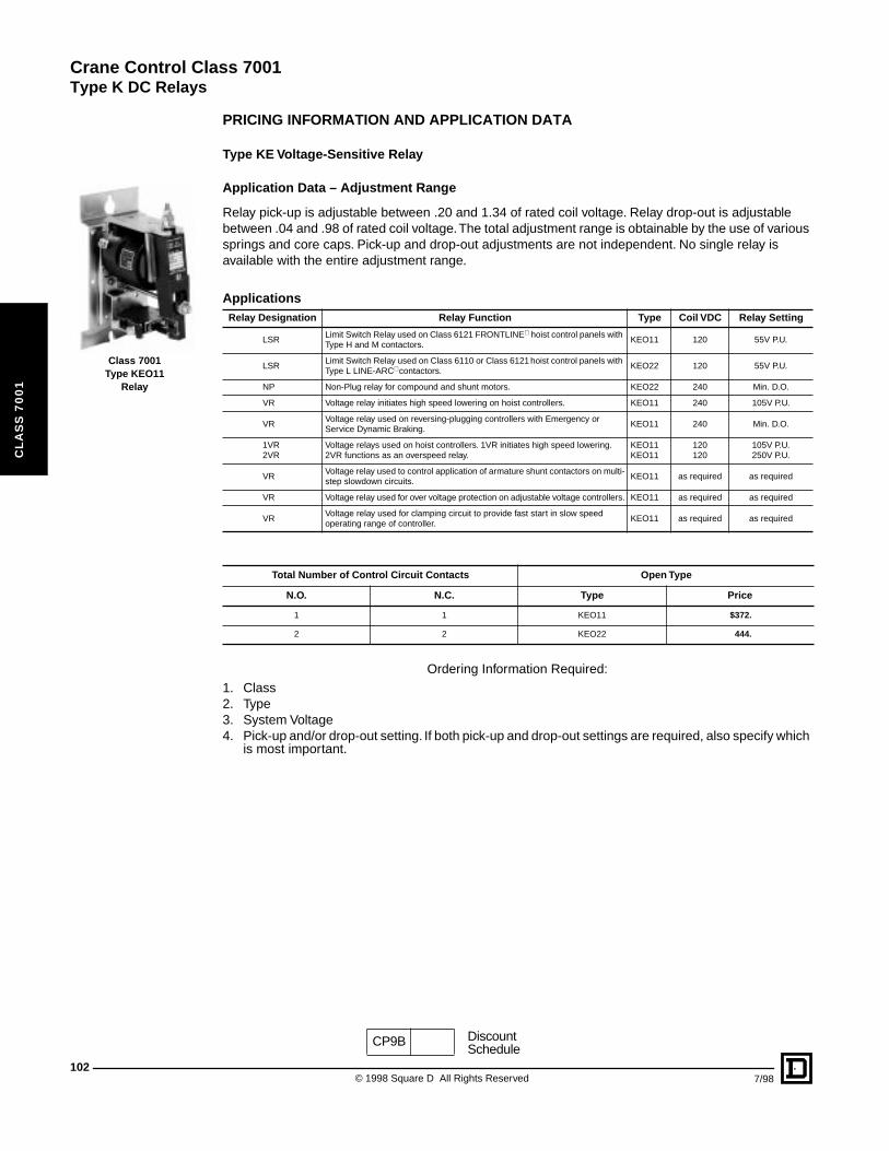
Crane Control Class 7001
Type K DC Relays
102
CL
AS
S 7
00
1
Class 7001Type KEO11
Relay
PRICING INFORMATION AND APPLICATION DATA
Type KE Voltage-Sensitive Relay
Application Data – Adjustment Range
Relay pick-up is adjustable between .20 and 1.34 of rated coil voltage. Relay drop-out is adjustable between .04 and .98 of rated coil voltage. The total adjustment range is obtainable by the use of various springs and core caps. Pick-up and drop-out adjustments are not independent. No single relay is available with the entire adjustment range.
Ordering Information Required:1. Class2. Type3. System Voltage4. Pick-up and/or drop-out setting. If both pick-up and drop-out settings are required, also specify which
is most important.
ApplicationsRelay Designation Relay Function Type Coil VDC Relay Setting
LSRLimit Switch Relay used on Class 6121 FRONTLINE hoist control panels with Type H and M contactors.
KEO11 120 55V P.U.
LSRLimit Switch Relay used on Class 6110 or Class 6121 hoist control panels with Type L LINE-ARC contactors.
KEO22 120 55V P.U.
NP Non-Plug relay for compound and shunt motors. KEO22 240 Min. D.O.
VR Voltage relay initiates high speed lowering on hoist controllers. KEO11 240 105V P.U.
VRVoltage relay used on reversing-plugging controllers with Emergency or Service Dynamic Braking.
KEO11 240 Min. D.O.
1VR2VR
Voltage relays used on hoist controllers. 1VR initiates high speed lowering. 2VR functions as an overspeed relay.
KEO11KEO11
120120
105V P.U.250V P.U.
VRVoltage relay used to control application of armature shunt contactors on multi-step slowdown circuits.
KEO11 as required as required
VR Voltage relay used for over voltage protection on adjustable voltage controllers. KEO11 as required as required
VRVoltage relay used for clamping circuit to provide fast start in slow speed operating range of controller.
KEO11 as required as required
Total Number of Control Circuit Contacts Open Type
N.O. N.C. Type Price
1 1 KEO11 $372.
2 2 KEO22 444.
CP9B DiscountSchedule
© 1998 Square D All Rights Reserved 7/98
Crane Control Class 7001
Type K DC Relays
7/98
CL
AS
S 7
00
1
Type KF Field Relay
■ For 1 N.C. contact in place of N.O. contact, specify Form NC▲ Pick-up and/or drop-out adjustment range is obtainable by use of various springs and core caps.
Ordering Information Required:
1. Class2. Type3. Form (Normally open or normally closed)4. System voltage (for shunt applications only) or Continuous current (for series applications only)5. Pick-up and/or drop-out settings. If both pick-up and drop-out settings are required, also specify
which is most important.
ApplicationsRelay
DesignationRelay Function Type
FAAcceleration of adjustable speed motors on weakened field. (Requires provision on the control with which it is used, for short-circuiting the relay contacts in order to provide full field during acceleration to base speed.)
KFO10 through KFO18
FFAAcceleration of adjustable speed motors on weakened field and provides full field during acceleration to base speed.
Consult Factory.
FKAcceleration and deceleration of adjustable speed motors. Provides full field during acceleration to base speed and during dynamic braking for stopping; also provides for acceleration on weakened field.
KFO50 through KFO58
FDDeceleration of adjustable speed motors by alternately strengthening and weakening the shunt field during dynamic braking.
KFO50 through KFO58 Form NC
UV Low voltage protective relay used on DC crane and mill controllers with protection. KFO70 through KFO73
Coils
Contacts ■
Open Type
TypeMax. Continuous
Amperes ▲(Series Coil)
Type Price
1 Series
7.411.718.8
1 N.O.KFO10KFO11KFO12
$ 513.
29.546.973.6
1 N.O.KFO13KFO14KFO15
513.
114172258
1 N.O.KFO16KFO17KFO18
513.
1 Series and 1 Shunt
7.411.718.8
1 N.O.KFO50KFO51KFO52
513.
29.546.973.6
1 N.O.KFO53KFO54KFO55
513.
114172258
1 N.O.KFO56KFO57KFO58
513.
1 Shunt
240 V120440550
1 N.O.
KFO70KFO71KFO72KFO73
513.
CP9B DiscountSchedule
103© 1998 Square D All Rights Reserved
Crane Control Class 7001
Type K DC Relays
104
CL
AS
S 7
00
1
Type KI Current Sensitive Relay
Application Data
For low currents, the terminals are on the operating coil. For higher current applications a wire wound or strap wound coil is used. Coil leads are brought to a power termination block at the top of the relay.
Adjustment Range
Relay pick-up is adjustable between .24 and 1.34 of rated coil current. Relay drop-out is adjustable between .20 and .98 of rated coil voltage. The total adjustment range is obtainable by the use of various springs and core caps. Pick-up and drop-out adjustments are not independent. The ratio of drop-out setting to pick-up setting of the relay must be between .13 and .85
Ordering Information Required:1. Class2. Type3. Continuous current4. System voltage5. Pick-up and drop-out settings
Applications
Relay Designation
Relay Function Type
FL Field Failure Relay for compound and shunt motors. KIO11
JR Jam Relay limits stall torque on series motors. KIO11
LR Load Relay operates at a preset current (load). KIO11
SR Series Relay used as shunt brake interlock relay. KIO11
Total Number of Control Circuit Contacts Open Type
N.O. N.C. Type Price
1 1 KIO11 $ 402.
2 2 KIO22 474.
Note: Maximum coil rating 258 A continuous. For higher current coils consult factory.
CP9B DiscountSchedule
© 1998 Square D All Rights Reserved 7/98
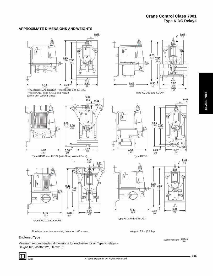
Crane Control Class 7001
Type K DC Relays
CL
AS
S 7
00
1
APPROXIMATE DIMENSIONS AND WEIGHTS
Enclosed Type
Minimum recommended dimensions for enclosure for all Type K relays – Height:16", Width: 12", Depth: 8".
6.42 0.3810163
3.8798
8.25210
1917.50
100.41
Type KGO11 and KGO22, Type KEO11 and KEO22,Type KPO11, Type KIO11 and KIO22(with Form Wound Coils)
6.42 0.3810163
3.8798
8.25210
1917.50
100.41
Type KPO5 Type KIO11 and KIO22 (with Strap Wound Coils)
0.3810
3.8798
8.25210
1917.50
100.41
6.42163
Type KFO70 thru KFO73Type KFO10 thru KFO69
100.41
8.25210
1917.50
3.8798
5.25133
0.3810
6.42163
Type KGO33 and KGO44
6.42163
0.3810
3.8798
8.25210
1917.50
100.41152
6.00
6.42163
0.3810
3.8798
8.25210
1917.50
100.41152
6.00
All relays have two mounting holes for 1/4'' screws. Weight - 7 lbs (3.2 kg)
Dual Dimensions inchesmm
1057/98 © 1998 Square D All Rights Reserved
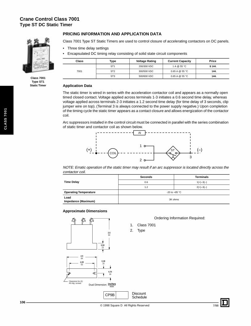
Crane Control Class 7001
Type ST DC Static Timer
106
CL
AS
S 7
00
1
Class 7001Type ST1
Static Timer
PRICING INFORMATION AND APPLICATION DATA
Class 7001 Type ST Static Timers are used to control closure of accelerating contactors on DC panels.
• Three time delay settings• Encapsulated DC timing relay consisting of solid state circuit components
Application Data
The static timer is wired in series with the acceleration contactor coil and appears as a normally open timed closed contact. Voltage applied across terminals 1-3 initiates a 0.6 second time delay, whereas voltage applied across terminals 2-3 initiates a 1.2 second time delay (for time delay of 3 seconds, clip jumper wire on top). (Terminal 3 is always connected to the power supply negative.) Upon completion of the timing cycle the static timer appears as a contact closure and allows energization of the contactor coil.
Arc suppressors installed in the control circuit must be connected in parallel with the series combination of static timer and contactor coil as shown below.
NOTE: Erratic operation of the static timer may result if an arc suppressor is located directly across the contactor coil.
Approximate Dimensions
Ordering Information Required:
1. Class 70012. Type
Class Type Voltage Rating Current Capacity Price
7001
ST1 200/300 VDC 1 A @ 55 °C $ 144.
ST2 300/500 VDC 0.65 A @ 55 °C 144.
ST3 500/600 VDC 0.65 A @ 55 °C 144.
Time Delay
Seconds Terminals
0.6 1(+)–3(–)
1.2 2(+)–3(–)
Operating Temperature -20 to +85 °C
LoadImpedance (Maximum)
3K ohms
COIL
AI
ST1
23
(–)(+)
13
53
64
10
19
64
mmDual Dimension:
0.50
2.09
2.5
0.38
0.75
2.5
inchesClearance for (2)#6 mtg. screws
CP9B DiscountSchedule
© 1998 Square D All Rights Reserved 7/98
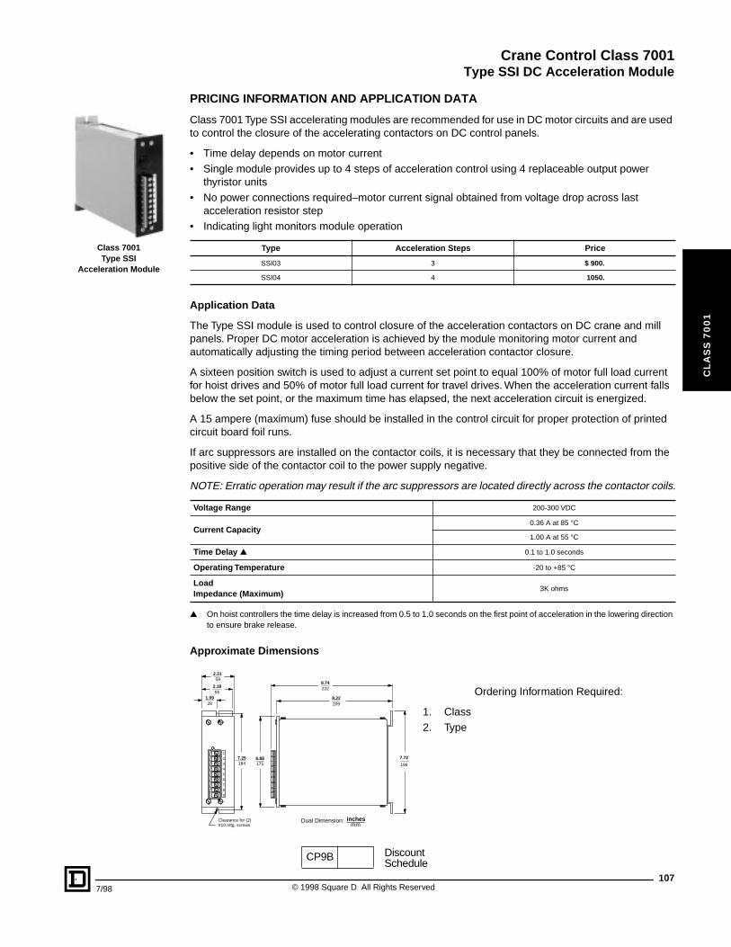
Crane Control Class 7001
Type SSI DC Acceleration Module
7/98
CL
AS
S 7
00
1
Class 7001Type SSI
Acceleration Module
PRICING INFORMATION AND APPLICATION DATA
Class 7001 Type SSI accelerating modules are recommended for use in DC motor circuits and are used to control the closure of the accelerating contactors on DC control panels.
• Time delay depends on motor current• Single module provides up to 4 steps of acceleration control using 4 replaceable output power
thyristor units• No power connections required–motor current signal obtained from voltage drop across last
acceleration resistor step• Indicating light monitors module operation
Application Data
The Type SSI module is used to control closure of the acceleration contactors on DC crane and mill panels. Proper DC motor acceleration is achieved by the module monitoring motor current and automatically adjusting the timing period between acceleration contactor closure.
A sixteen position switch is used to adjust a current set point to equal 100% of motor full load current for hoist drives and 50% of motor full load current for travel drives. When the acceleration current falls below the set point, or the maximum time has elapsed, the next acceleration circuit is energized.
A 15 ampere (maximum) fuse should be installed in the control circuit for proper protection of printed circuit board foil runs.
If arc suppressors are installed on the contactor coils, it is necessary that they be connected from the positive side of the contactor coil to the power supply negative.
NOTE: Erratic operation may result if the arc suppressors are located directly across the contactor coils.
▲ On hoist controllers the time delay is increased from 0.5 to 1.0 seconds on the first point of acceleration in the lowering direction to ensure brake release.
Approximate Dimensions
Ordering Information Required:
1. Class 2. Type
Type Acceleration Steps Price
SSI03 3 $ 900.
SSI04 4 1050.
Voltage Range 200-300 VDC
Current Capacity0.36 A at 85 °C
1.00 A at 55 °C
Time Delay ▲ 0.1 to 1.0 seconds
Operating Temperature -20 to +85 °C
LoadImpedance (Maximum)
3K ohms
1
9
8
7
6
5
4
3
2
28
184 175
209
196
222
59
551.09
7.25 6.88
8.22
7.72
8.74
2.31
2.18
Clearance for (2)#10 mtg. screws mm
Dual Dimension: inches
CP9B DiscountSchedule
107© 1998 Square D All Rights Reserved
Crane Control Class 7001
108
CL
AS
S 7
00
1
© 1998 Square D All Rights Reserved 7/98
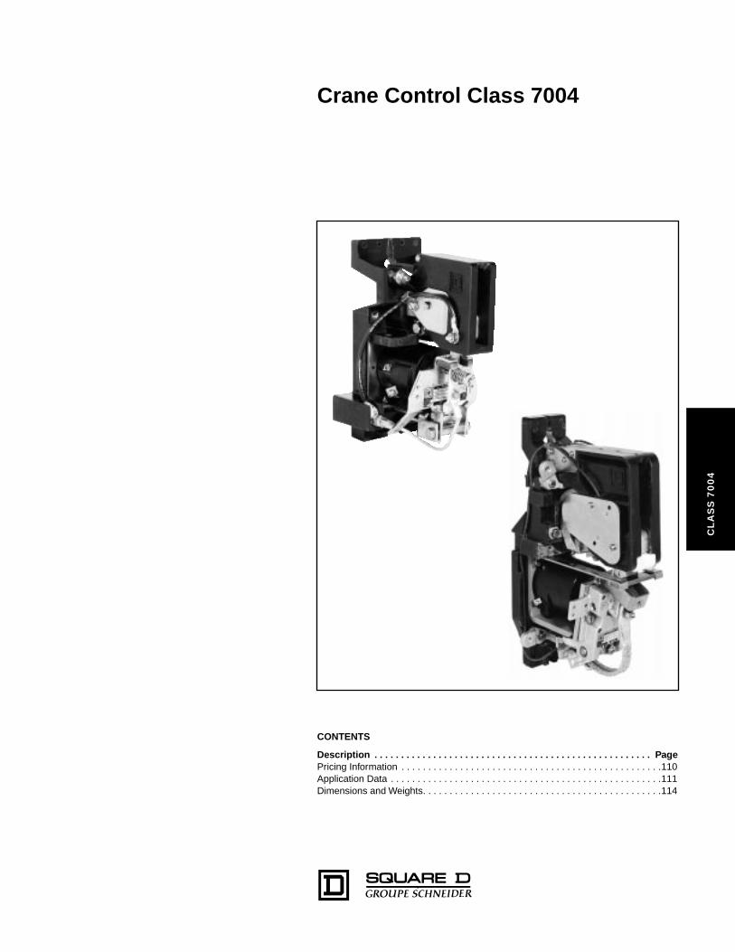
Crane Control Class 7004
CL
AS
S 7
00
4
CONTENTS
Description . . . . . . . . . . . . . . . . . . . . . . . . . . . . . . . . . . . . . . . . . . . . . . . . . . . . PagePricing Information . . . . . . . . . . . . . . . . . . . . . . . . . . . . . . . . . . . . . . . . . . . . . . . . .110Application Data . . . . . . . . . . . . . . . . . . . . . . . . . . . . . . . . . . . . . . . . . . . . . . . . . . .111Dimensions and Weights. . . . . . . . . . . . . . . . . . . . . . . . . . . . . . . . . . . . . . . . . . . . .114
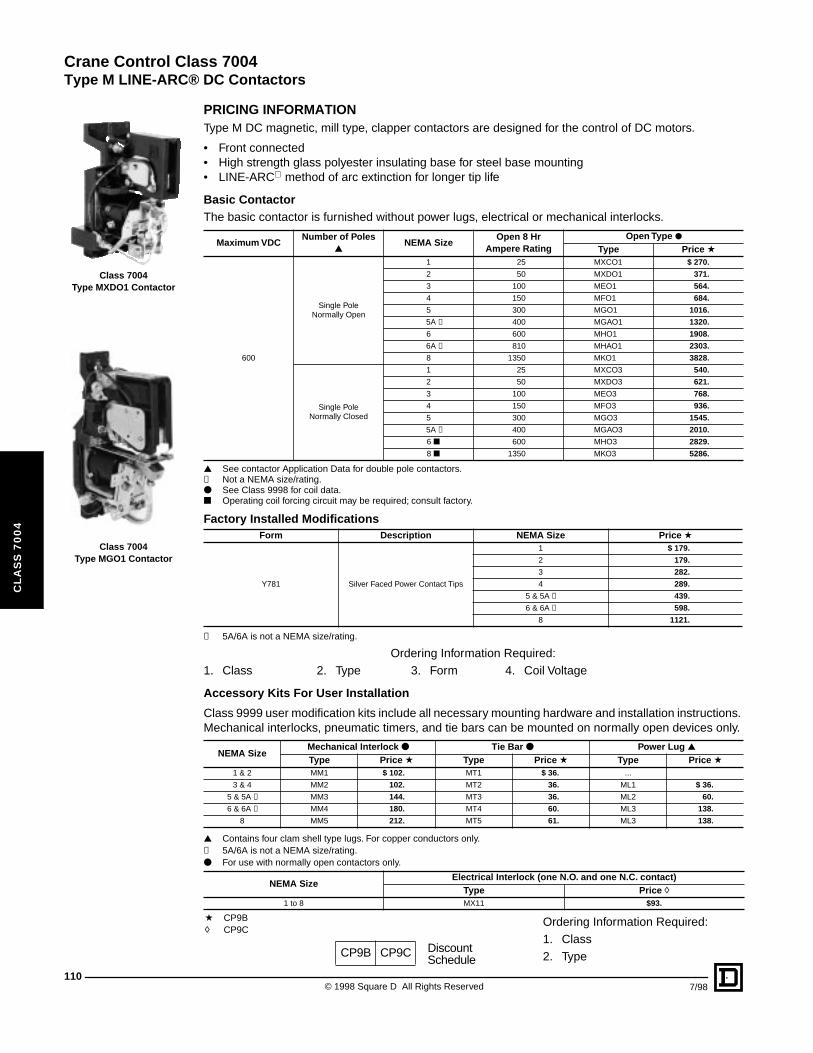
Crane Control Class 7004
Type M LINE-ARC® DC Contactors
110
CL
AS
S 7
00
4
Class 7004 Type MXDO1 Contactor
Class 7004 Type MGO1 Contactor
CP9B CP9C DiscountSchedule
PRICING INFORMATIONType M DC magnetic, mill type, clapper contactors are designed for the control of DC motors.
• Front connected• High strength glass polyester insulating base for steel base mounting• LINE-ARC method of arc extinction for longer tip life
Basic ContactorThe basic contactor is furnished without power lugs, electrical or mechanical interlocks.
▲ See contactor Application Data for double pole contactors.✝ Not a NEMA size/rating.● See Class 9998 for coil data.■ Operating coil forcing circuit may be required; consult factory.
✝ 5A/6A is not a NEMA size/rating.
Ordering Information Required:1. Class 2. Type 3. Form 4. Coil Voltage
Accessory Kits For User Installation
Class 9999 user modification kits include all necessary mounting hardware and installation instructions. Mechanical interlocks, pneumatic timers, and tie bars can be mounted on normally open devices only.
▲ Contains four clam shell type lugs. For copper conductors only.✝ 5A/6A is not a NEMA size/rating.● For use with normally open contactors only.
Ordering Information Required:1. Class2. Type
Maximum VDCNumber of Poles
▲NEMA Size
Open 8 HrAmpere Rating
Open Type ●Type Price a
600
Single Pole Normally Open
1 25 MXCO1 $ 270.
2 50 MXDO1 371.
3 100 MEO1 564.
4 150 MFO1 684.
5 300 MGO1 1016.
5A ✝ 400 MGAO1 1320.
6 600 MHO1 1908.
6A ✝ 810 MHAO1 2303.
8 1350 MKO1 3828.
Single Pole Normally Closed
1 25 MXCO3 540.
2 50 MXDO3 621.
3 100 MEO3 768.
4 150 MFO3 936.
5 300 MGO3 1545.
5A ✝ 400 MGAO3 2010.
6 ■ 600 MHO3 2829.
8 ■ 1350 MKO3 5286.
Factory Installed ModificationsForm Description NEMA Size Price a
Y781 Silver Faced Power Contact Tips
1 $ 179.
2 179.
3 282.
4 289.
5 & 5A ✝ 439.
6 & 6A ✝ 598.
8 1121.
NEMA SizeMechanical Interlock ● Tie Bar ● Power Lug ▲Type Price a Type Price a Type Price a
1 & 2 MM1 $ 102. MT1 $ 36. ...
3 & 4 MM2 102. MT2 36. ML1 $ 36.
5 & 5A ✝ MM3 144. MT3 36. ML2 60.
6 & 6A ✝ MM4 180. MT4 60. ML3 138.
8 MM5 212. MT5 61. ML3 138.
NEMA SizeElectrical Interlock (one N.O. and one N.C. contact)
Type Price h1 to 8 MX11 $93.
a CP9Bh CP9C
© 1998 Square D All Rights Reserved 7/98
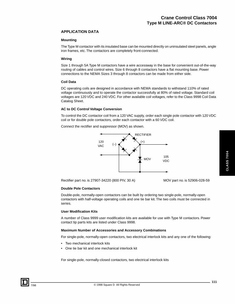
Crane Control Class 7004
Type M LINE-ARC® DC Contactors
7/98
CL
AS
S 7
00
4
APPLICATION DATA
Mounting
The Type M contactor with its insulated base can be mounted directly on uninsulated steel panels, angle iron frames, etc. The contactors are completely front-connected.
Wiring
Size 1 through 5A Type M contactors have a wire accessway in the base for convenient out-of-the-way routing of cables and control wires. Size 6 through 8 contactors have a flat mounting base. Power connections to the NEMA Sizes 3 through 8 contactors can be made from either side.
Coil Data
DC operating coils are designed in accordance with NEMA standards to withstand 110% of rated voltage continuously and to operate the contactor successfully at 80% of rated voltage. Standard coil voltages are 120 VDC and 240 VDC. For other available coil voltages, refer to the Class 9998 Coil Data Catalog Sheet.
AC to DC Control Voltage Conversion
To control the DC contactor coil from a 120 VAC supply, order each single pole contactor with 120 VDC coil or for double pole contactors, order each contactor with a 60 VDC coil.
Connect the rectifier and suppressor (MOV) as shown.
Rectifier part no. is 27907-34220 (800 PIV, 30 A) MOV part no. is 52906-028-59
Double Pole Contactors
Double-pole, normally-open contactors can be built by ordering two single-pole, normally-open contactors with half-voltage operating coils and one tie bar kit. The two coils must be connected in series.
User Modification Kits
A number of Class 9999 user modification kits are available for use with Type M contactors. Power contact tip parts kits are listed under Class 9998.
Maximum Number of Accessories and Accessory Combinations
For single-pole, normally-open contactors, two electrical interlock kits and any one of the following:
• Two mechanical interlock kits• One tie bar kit and one mechanical interlock kit
For single-pole, normally-closed contactors, two electrical interlock kits
(+)(–)
RECTIFIER
MOV
120
105
VAC
VDC
111© 1998 Square D All Rights Reserved
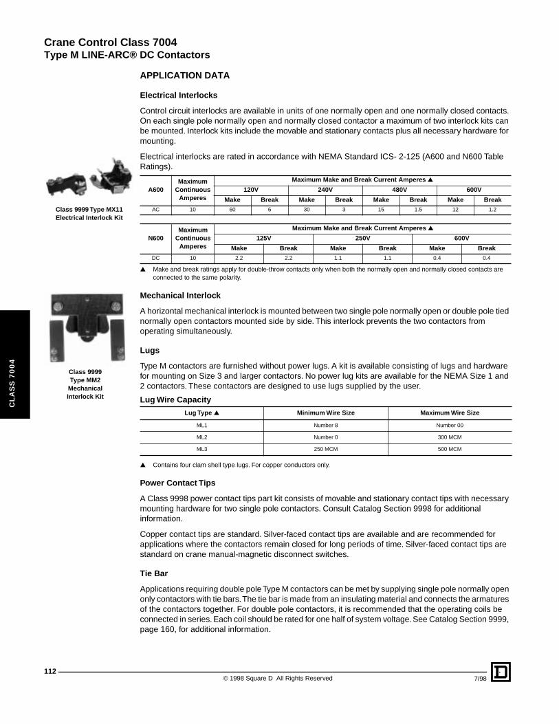
Crane Control Class 7004
Type M LINE-ARC® DC Contactors
112
CL
AS
S 7
00
4
Class 9999 Type MX11Electrical Interlock Kit
Class 9999Type MM2
MechanicalInterlock Kit
APPLICATION DATA
Electrical Interlocks
Control circuit interlocks are available in units of one normally open and one normally closed contacts. On each single pole normally open and normally closed contactor a maximum of two interlock kits can be mounted. Interlock kits include the movable and stationary contacts plus all necessary hardware for mounting.
Electrical interlocks are rated in accordance with NEMA Standard ICS- 2-125 (A600 and N600 Table Ratings).
▲ Make and break ratings apply for double-throw contacts only when both the normally open and normally closed contacts are connected to the same polarity.
Mechanical Interlock
A horizontal mechanical interlock is mounted between two single pole normally open or double pole tied normally open contactors mounted side by side. This interlock prevents the two contactors from operating simultaneously.
Lugs
Type M contactors are furnished without power lugs. A kit is available consisting of lugs and hardware for mounting on Size 3 and larger contactors. No power lug kits are available for the NEMA Size 1 and 2 contactors. These contactors are designed to use lugs supplied by the user.
▲ Contains four clam shell type lugs. For copper conductors only.
Power Contact Tips
A Class 9998 power contact tips part kit consists of movable and stationary contact tips with necessary mounting hardware for two single pole contactors. Consult Catalog Section 9998 for additional information.
Copper contact tips are standard. Silver-faced contact tips are available and are recommended for applications where the contactors remain closed for long periods of time. Silver-faced contact tips are standard on crane manual-magnetic disconnect switches.
Tie Bar
Applications requiring double pole Type M contactors can be met by supplying single pole normally open only contactors with tie bars. The tie bar is made from an insulating material and connects the armatures of the contactors together. For double pole contactors, it is recommended that the operating coils be connected in series. Each coil should be rated for one half of system voltage. See Catalog Section 9999, page 160, for additional information.
A600Maximum
Continuous Amperes
Maximum Make and Break Current Amperes ▲
120V 240V 480V 600V
Make Break Make Break Make Break Make BreakAC 10 60 6 30 3 15 1.5 12 1.2
N600Maximum
Continuous Amperes
Maximum Make and Break Current Amperes ▲
125V 250V 600V
Make Break Make Break Make BreakDC 10 2.2 2.2 1.1 1.1 0.4 0.4
Lug Wire Capacity
Lug Type ▲ Minimum Wire Size Maximum Wire Size
ML1 Number 8 Number 00
ML2 Number 0 300 MCM
ML3 250 MCM 500 MCM
© 1998 Square D All Rights Reserved 7/98
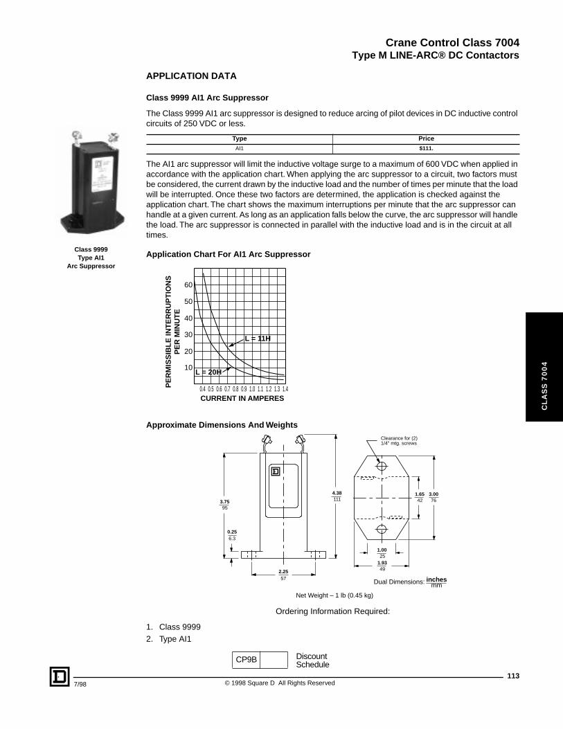
Crane Control Class 7004
Type M LINE-ARC® DC Contactors
7/98
CL
AS
S 7
00
4
Class 9999Type AI1
Arc Suppressor
APPLICATION DATA
Class 9999 AI1 Arc Suppressor
The Class 9999 AI1 arc suppressor is designed to reduce arcing of pilot devices in DC inductive control circuits of 250 VDC or less.
The AI1 arc suppressor will limit the inductive voltage surge to a maximum of 600 VDC when applied in accordance with the application chart. When applying the arc suppressor to a circuit, two factors must be considered, the current drawn by the inductive load and the number of times per minute that the load will be interrupted. Once these two factors are determined, the application is checked against the application chart. The chart shows the maximum interruptions per minute that the arc suppressor can handle at a given current. As long as an application falls below the curve, the arc suppressor will handle the load. The arc suppressor is connected in parallel with the inductive load and is in the circuit at all times.
Application Chart For AI1 Arc Suppressor
Approximate Dimensions And Weights
Ordering Information Required:
1. Class 99992. Type AI1
Type PriceAI1 $111.
10
CURRENT IN AMPERES
PE
RM
ISS
IBL
E IN
TE
RR
UP
TIO
NS
PE
R M
INU
TE
0.4 0.5 0.6 0.7 0.8 0.9 1.0 1.1 1.2 1.3 1.4
20
30
40
50
60
L = 11H
L = 20H
57
111
25
49
42 76
6.3
95
2.25
4.38
1.00
1.93
1.65 3.00
0.25
3.75
Clearance for (2)1/4" mtg. screws
mmDual Dimensions: inches
Net Weight – 1 lb (0.45 kg)
CP9B DiscountSchedule
113© 1998 Square D All Rights Reserved

Crane Control Class 7004
Type M LINE-ARC® DC Contactors
114
CL
AS
S 7
00
4
APPROXIMATE DIMENSIONS
C2C1
E
K
D
X
Y
Arcing clearancezoneH A
S S
Q
B
for screw "F"2 Mtg. holes
Figure 1
NEMA SIZES 1, 2SPNO AND SPNC
C1C2
Z E
K
D
X
Y
Arcing clearancezone
4 "G" tappedholesMain Terminals
2 Mtg. holesfor screw "F"
Q
B
A A
H H
S S
Figure 2
NEMA SIZES 3, 4, & 5SPNO AND SPNC
SIZE 5ASPNO AND SPNC
A AL
K
Q B D
S S
H H
4 Mtg. holesfor screw "F"
C1
C2
E Z X
Y
4 "G" tappedholesMain Terminal
Arcing clearancezone
Figure 3
NEMA SIZES 6, 8SPNO AND SPNCAND SIZE 6A SPNO
© 1998 Square D All Rights Reserved 7/98
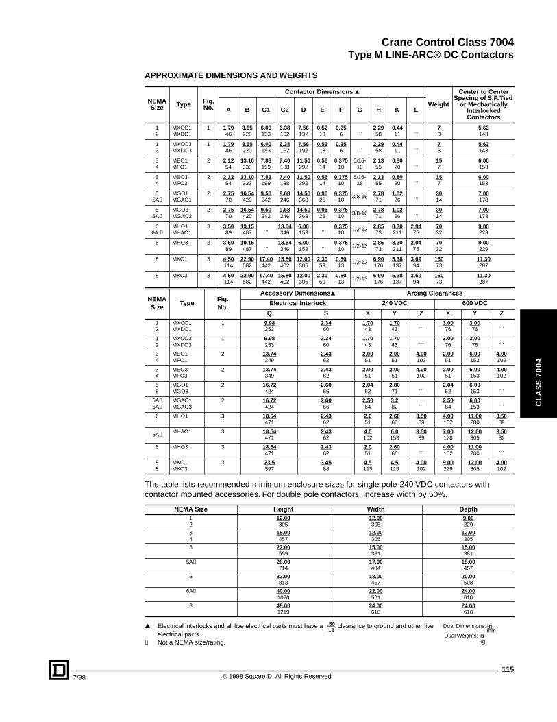
Crane Control Class 7004
Type M LINE-ARC® DC Contactors
7/98
CL
AS
S 7
00
4
APPROXIMATE DIMENSIONS AND WEIGHTS
The table lists recommended minimum enclosure sizes for single pole-240 VDC contactors with contactor mounted accessories. For double pole contactors, increase width by 50%.
▲ Electrical interlocks and all live electrical parts must have a clearance to ground and other live electrical parts.
✝ Not a NEMA size/rating.
NEMASize Type Fig.
No.
Contactor Dimensions ▲
Weight
Center to Center Spacing of S.P. Tied
or Mechanically Interlocked Contactors
A B C1 C2 D E F G H K L
12
MXCO1MXDO1
1 1.7946
8.65220
6.00153
6.38162
7.56192
0.5213
0.256
...2.2958
0.4411
...73
5.63143
12
MXCO3MXDO3
1 1.7946
8.65220
6.00153
6.38162
7.56192
0.5213
0.256
...2.2958
0.4411
...73
5.63143
34
MEO1MFO1
2 2.1254
13.10333
7.83199
7.40188
11.50292
0.5614
0.37510
5/16-18
2.1355
0.8020
...157
6.00153
34
MEO3MFO3
2 2.1254
13.10333
7.83199
7.40188
11.50292
0.5614
0.37510
5/16-18
2.1355
0.8020
...157
6.00153
55A✝
MGO1MGAO1
2 2.7570
16.54420
9.50242
9.68246
14.50368
0.9625
0.37510
3/8-162.7871
1.0226
...3014
7.00178
55A✝
MGO3MGAO3
2 2.7570
16.54420
9.50242
9.68246
14.50368
0.9625
0.37510
3/8-162.7871
1.0226
...3014
7.00178
66A ✝
MHO1MHAO1
3 3.5089
19.15487
...13.64346
6.00153
...0.375
101/2-13
2.8573
8.30211
2.9475
7032
9.00229
6 MHO3 3 3.5089
19.15487
...13.64346
6.00153
...0.375
101/2-13
2.8573
8.30211
2.9475
7032
9.00229
8 MKO1 3 4.50114
22.90582
17.40442
15.80402
12.00305
2.3059
0.5013
1/2-136.90176
5.38137
3.6994
16073
11.30287
8 MKO3 3 4.50114
22.90582
17.40442
15.80402
12.00305
2.3059
0.5013
1/2-136.90176
5.38137
3.6994
16073
11.30287
NEMASize
TypeFig.No.
Accessory Dimensions▲ Arcing Clearances
Electrical Interlock 240 VDC 600 VDC
Q S X Y Z X Y Z12
MXCO1MXDO1
1 9.98253
2.3460
1.7043
1.7043
...3.0076
3.0076
...
12
MXCO3MXDO3
1 9.98253
2.3460
1.7043
1.7043
...3.0076
3.0076
...
34
MEO1MFO1
2 13.74349
2.4362
2.0051
2.0051
4.00102
2.0051
6.00153
4.00102
34
MEO3MFO3
2 13.74349
2.4362
2.0051
2.0051
4.00102
2.0051
6.00153
4.00102
55
MGO1MGO3
2 16.72424
2.6066
2.0452
2.8071
...2.0452
6.00153
...
5A✝5A✝
MGAO1MGAO3
2 16.72424
2.6066
2.5064
3.282
...2.5064
6.00153
...
6 MHO1 3 18.54471
2.4362
2.051
2.6066
3.5089
4.00102
11.00280
3.5089
6A✝MHAO1 3 18.54
4712.4362
4.0102
6.0153
3.5089
7.00178
12.00305
3.5089
6 MHO3 3 18.54471
2.4362
2.051
2.6066
...4.00102
11.00280
...
88
MKO1MKO3
3 23.5597
3.4588
4.5115
4.5115
4.00102
9.00229
12.00305
4.00102
NEMA Size Height Width Depth12
12.00305
12.00305
9.00229
34
18.00457
12.00305
12.00305
5 22.00559
15.00381
15.00381
5A✝ 28.00714
17.00434
18.00457
6 32.00813
18.00457
20.00508
6A✝ 40.001020
22.00561
24.00610
8 48.001219
24.00610
24.00610
Dual Dimensions: inmm
Dual Weights: lbkg
13.50
115© 1998 Square D All Rights Reserved
Crane Control Class 7004
116
CL
AS
S 7
00
4
© 1998 Square D All Rights Reserved 7/98
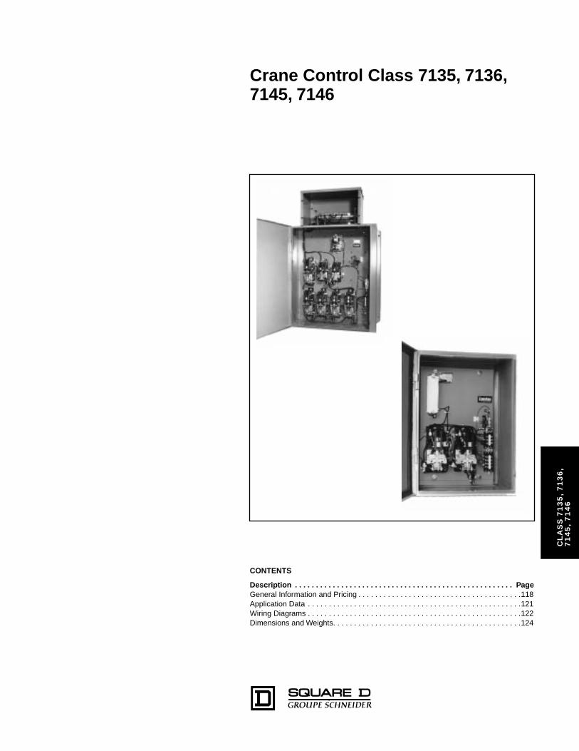
Crane Control Class 7135, 7136, 7145, 7146
SS
71
35
, 7
13
6,
5,
71
46
CL
A7
14
CONTENTS
Description . . . . . . . . . . . . . . . . . . . . . . . . . . . . . . . . . . . . . . . . . . . . . . . . . . . . PageGeneral Information and Pricing . . . . . . . . . . . . . . . . . . . . . . . . . . . . . . . . . . . . . . .118Application Data . . . . . . . . . . . . . . . . . . . . . . . . . . . . . . . . . . . . . . . . . . . . . . . . . . .121Wiring Diagrams . . . . . . . . . . . . . . . . . . . . . . . . . . . . . . . . . . . . . . . . . . . . . . . . . . .122Dimensions and Weights. . . . . . . . . . . . . . . . . . . . . . . . . . . . . . . . . . . . . . . . . . . . .124
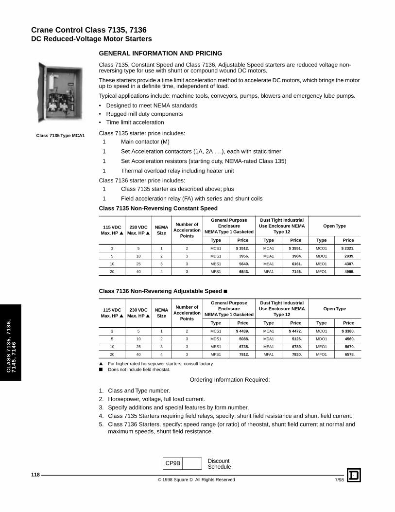
Crane Control Class 7135, 7136
DC Reduced-Voltage Motor Starters
118
CL
AS
S 7
13
5,
71
36
, 7
14
5,
71
46
Class 7135 Type MCA1
GENERAL INFORMATION AND PRICING
Class 7135, Constant Speed and Class 7136, Adjustable Speed starters are reduced voltage non-reversing type for use with shunt or compound wound DC motors.
These starters provide a time limit acceleration method to accelerate DC motors, which brings the motor up to speed in a definite time, independent of load.
Typical applications include: machine tools, conveyors, pumps, blowers and emergency lube pumps.
• Designed to meet NEMA standards• Rugged mill duty components• Time limit acceleration
Class 7135 starter price includes:1 Main contactor (M)
1 Set Acceleration contactors (1A, 2A . . .), each with static timer
1 Set Acceleration resistors (starting duty, NEMA-rated Class 135)
1 Thermal overload relay including heater unit
Class 7136 starter price includes:1 Class 7135 starter as described above; plus
1 Field acceleration relay (FA) with series and shunt coils
▲ For higher rated horsepower starters, consult factory.■ Does not include field rheostat.
Ordering Information Required:
1. Class and Type number.2. Horsepower, voltage, full load current.3. Specify additions and special features by form number.4. Class 7135 Starters requiring field relays, specify: shunt field resistance and shunt field current.5. Class 7136 Starters, specify: speed range (or ratio) of rheostat, shunt field current at normal and
maximum speeds, shunt field resistance.
Class 7135 Non-Reversing Constant Speed
115 VDCMax. HP ▲
230 VDCMax. HP ▲
NEMA Size
Number of Acceleration
Points
General Purpose Enclosure
NEMA Type 1 Gasketed
Dust Tight Industrial Use Enclosure NEMA
Type 12Open Type
Type Price Type Price Type Price
3 5 1 2 MCS1 $ 3512. MCA1 $ 3551. MCO1 $ 2321.
5 10 2 3 MDS1 3956. MDA1 3984. MDO1 2939.
10 25 3 3 MES1 5640. MEA1 6161. MEO1 4307.
20 40 4 3 MFS1 6543. MFA1 7146. MFO1 4995.
Class 7136 Non-Reversing Adjustable Speed ■
115 VDCMax. HP ▲
230 VDCMax. HP ▲
NEMA Size
Number of Acceleration
Points
General Purpose Enclosure
NEMA Type 1 Gasketed
Dust Tight Industrial Use Enclosure NEMA
Type 12Open Type
Type Price Type Price Type Price
3 5 1 2 MCS1 $ 4439. MCA1 $ 4472. MCO1 $ 3380.
5 10 2 3 MDS1 5088. MDA1 5126. MDO1 4560.
10 25 3 3 MES1 6735. MEA1 6789. MEO1 5670.
20 40 4 3 MFS1 7812. MFA1 7830. MFO1 6578.
CP9B DiscountSchedule
© 1998 Square D All Rights Reserved 7/98
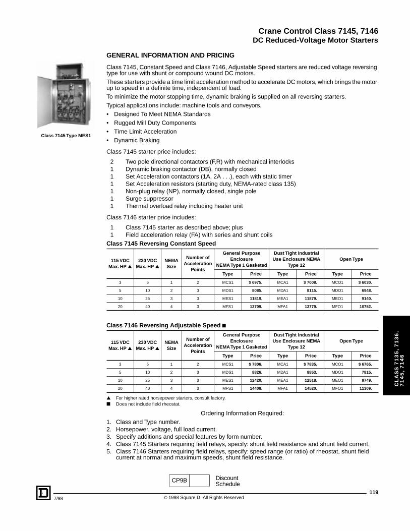
Crane Control Class 7145, 7146
DC Reduced-Voltage Motor Starters
7/98
CL
AS
S 7
13
5,
71
36
, 7
14
5,
71
46
Class 7145 Type MES1
GENERAL INFORMATION AND PRICING
Class 7145, Constant Speed and Class 7146, Adjustable Speed starters are reduced voltage reversing type for use with shunt or compound wound DC motors.These starters provide a time limit acceleration method to accelerate DC motors, which brings the motor up to speed in a definite time, independent of load.To minimize the motor stopping time, dynamic braking is supplied on all reversing starters.Typical applications include: machine tools and conveyors.• Designed To Meet NEMA Standards• Rugged Mill Duty Components• Time Limit Acceleration• Dynamic Braking
Class 7145 starter price includes:
2 Two pole directional contactors (F,R) with mechanical interlocks1 Dynamic braking contactor (DB), normally closed1 Set Acceleration contactors (1A, 2A . . .), each with static timer1 Set Acceleration resistors (starting duty, NEMA-rated class 135)1 Non-plug relay (NP), normally closed, single pole1 Surge suppressor1 Thermal overload relay including heater unit
Class 7146 starter price includes:
1 Class 7145 starter as described above; plus1 Field acceleration relay (FA) with series and shunt coils
▲ For higher rated horsepower starters, consult factory.■ Does not include field rheostat.
Ordering Information Required:1. Class and Type number.2. Horsepower, voltage, full load current.3. Specify additions and special features by form number.4. Class 7145 Starters requiring field relays, specify: shunt field resistance and shunt field current.5. Class 7146 Starters requiring field relays, specify: speed range (or ratio) of rheostat, shunt field
current at normal and maximum speeds, shunt field resistance.
Class 7145 Reversing Constant Speed
115 VDCMax. HP ▲
230 VDCMax. HP ▲
NEMA Size
Number of Acceleration
Points
General Purpose Enclosure
NEMA Type 1 Gasketed
Dust Tight Industrial Use Enclosure NEMA
Type 12Open Type
Type Price Type Price Type Price
3 5 1 2 MCS1 $ 6975. MCA1 $ 7008. MCO1 $ 6030.
5 10 2 3 MDS1 8085. MDA1 8115. MDO1 6948.
10 25 3 3 MES1 11819. MEA1 11879. MEO1 9140.
20 40 4 3 MFS1 13709. MFA1 13779. MFO1 10752.
Class 7146 Reversing Adjustable Speed ■
115 VDCMax. HP ▲
230 VDCMax. HP ▲
NEMA Size
Number of Acceleration
Points
General Purpose Enclosure
NEMA Type 1 Gasketed
Dust Tight Industrial Use Enclosure NEMA
Type 12Open Type
Type Price Type Price Type Price
3 5 1 2 MCS1 $ 7806. MCA1 $ 7835. MCO1 $ 6765.
5 10 2 3 MDS1 8826. MDA1 8853. MDO1 7815.
10 25 3 3 MES1 12420. MEA1 12518. MEO1 9749.
20 40 4 3 MFS1 14408. MFA1 14520. MFO1 11309.
CP9B DiscountSchedule
119© 1998 Square D All Rights Reserved
Crane Control Class 7135, 7136, 7145, 7146
DC Reduced-Voltage Motor Starters
120
CL
AS
S 7
13
5,
71
36
, 7
14
5,
71
46
MODIFICATIONS, PRICING AND APPLICATION DATA
▲ Specify contact arrangement.a Specify shunt field data.
Additions and Special Features Form Number
PanelSpace
Price NEMA Size Starter
1 2 3 4
Power Knife Switch
With DC rated fuses, operable from inside enclosure D1 2 $ 1035. $ 1165. $ 2570. $ 4065.
Non-fused, operable from inside enclosure D9 1 690. 690. 785. 1052.
Molded Case Switch
With DC rated fuses, operable from outside enclosure D4 2 $ 930. $ 1050. $ 2315. $ 3660.
Non-fused, operable from outside enclosure D5 1 620. 620. 710. 950.
Additions and Special Features Form Number
Panel Space Price
Pilot Devices (Flange mounted)
“Start-Stop” push button A – $ 204.
“Forward-Reverse-Stop” push button A1 – 345.
“On-Off” push button A3 – 204.
“Hand-Off-Auto” selector switch C – 204.
Pilot light (specify color) (P1 = red, P2 = green, P37 = white) P_ – 204.
Control Circuit Modifications
Control Circuit knife switch (fusible) D19 1 264.
Terminal board space for remote pilot devices, per terminal point G50 – 63.
Extra electrical interlocks (1 N.O. and 1 N.C.) X11 – 158.
Auxiliary and Protective Relays
Undervoltage relay R1 1 660.
Field decelerating relay (limits motor armature current while motor is decelerating to base speed) R3 1 759.
Field Loss relay (disconnects motor from line in event of loss of field) R4 a 1 609.
Field economizing relay (relay inserts resistance in shunt field to prevent overheating of field winding when motor is at rest)
R5 a 1 759.
Jog control relay:Non-Reversing (Class 7135, 7136) – 1 relayReversing (Class 7145, 7146) – 2 relays
R16R27
11
609.917.
Control relay R17 ▲ 1 609.
CP9B DiscountSchedule
© 1998 Square D All Rights Reserved 7/98

Crane Control Class 7135, 7136, 7145, 7146
DC Reduced-Voltage Motor Starters
7/98
CL
AS
S 7
13
5,
71
36
, 7
14
5,
71
46
COMPONENT EQUIPMENT
CONTACTORS
Main (M), Reversing (F&R), Acceleration (1A, 2A, 3A), Dynamic Braking (DB).
Construction – Clapper type, Square D Class 7004, Type MX on Sizes 1 and 2; Type M on Sizes 3 and 4.
Volts – 600 VDC Maximum.
CURRENT RATING
Contact Tips – Copper
Coil – 120 or 240 VDC, operating range, 110 to 80% of rated voltage.
Auxiliary Contacts – Maximum 2 N.O. + 2 N.C. 10 ADC, double break. Interrupting rating (inductive) is 2.2 A, 1.1 A and 0.4 A at 125V , 250 V and 600 V, respectively.
Lugs – NEMA Size 1 and 2, box lug type; NEMA Size 3 and higher, clam-shell type.
CONTROL CIRCUIT
Wiring – Stranded, 600 V, 90 °C rating.
Overloads – Class 9065, single pole, hand reset melting alloy.
Push buttons – Class 9001, Type K, 10 A continuous rating.
Fuses – 15 A, 250 VDC
Pilot Lights – Class 9001, Type K.
Terminal Blocks – Class 9080, Type GR, 600 V rating, maximum wire 2- #12.
Acceleration Timers – Class 7001, Type ST1, non-adjustable static timer(s), provide 1.2 seconds accelerating time for each acceleration contactor. The static timer is wired in series with the acceleration contactor coil and appears as a normally open timed closed contact.
Accelerating Resistors – These starting duty resistors will provide starting torques of at least 150% of motor full load torque. The resistor designs permit 10 seconds on out of each 80 seconds.
NEMA Size 1 2 3 4Open 25 A 50 A 100 A 150 A
Enclosed 22 A 45 A 90 A 135 A
NEMA Size Number Acceleration Contactors1 1
2 2
3 2
4 2
121© 1998 Square D All Rights Reserved
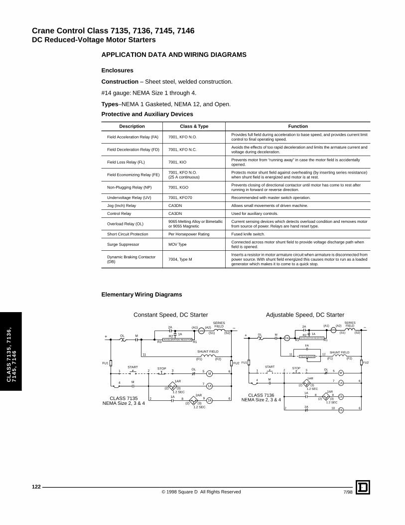
Crane Control Class 7135, 7136, 7145, 7146
DC Reduced-Voltage Motor Starters
122
CL
AS
S 7
13
5,
71
36
, 7
14
5,
71
46
APPLICATION DATA AND WIRING DIAGRAMS
Enclosures
Construction – Sheet steel, welded construction.
#14 gauge: NEMA Size 1 through 4.
Types–NEMA 1 Gasketed, NEMA 12, and Open.
Elementary Wiring Diagrams
Protective and Auxiliary Devices
Description Class & Type Function
Field Acceleration Relay (FA) 7001, KFO N.O.Provides full field during acceleration to base speed, and provides current limit control to final operating speed.
Field Deceleration Relay (FD) 7001, KFO N.C.Avoids the effects of too rapid deceleration and limits the armature current and voltage during deceleration.
Field Loss Relay (FL) 7001, KIOPrevents motor from “running away” in case the motor field is accidentally opened.
Field Economizing Relay (FE)7001, KFO N.O.(25 A continuous)
Protects motor shunt field against overheating (by inserting series resistance) when shunt field is energized and motor is at rest.
Non-Plugging Relay (NP) 7001, KGOPrevents closing of directional contactor until motor has come to rest after running in forward or reverse direction.
Undervoltage Relay (UV) 7001, KFO70 Recommended with master switch operation.
Jog (Inch) Relay CA3DN Allows small movements of driven machine.
Control Relay CA3DN Used for auxiliary controls.
Overload Relay (OL)9065 Melting Alloy or Bimetallic or 9055 Magnetic
Current sensing devices which detects overload condition and removes motor from source of power. Relays are hand reset type.
Short Circuit Protection Per Horsepower Rating Fused knife switch.
Surge Suppressor MOV TypeConnected across motor shunt field to provide voltage discharge path when field is opened.
Dynamic Braking Contactor (DB)
7004, Type MInserts a resistor in motor armature circuit when armature is disconnected from power source. With shunt field energized this causes motor to run as a loaded generator which makes it to come to a quick stop.
+
–
CLASS 7135
ACCELERATION RESISTOR
NEMA Size 2, 3 & 4
R21A
ARM(A1) (A2) FIELD
SERIES
(S1) (S2)
R3
2A
MOL
R1
SHUNT FIELD
(F1) (F2)
1A
2A
OL
(2) (3)
1AR
2AR
1.2 SEC
(2) (3)1.2 SEC
FU1 FU2
5
7
9
M4
2
START STOP3
11
1A8
M1 2 6
6
+
–
CLASS 7136
ACCELERATION RESISTOR
NEMA Size 2, 3 & 4
R2 1AARM
(A1) (A2) FIELDSERIES
(S1) (S2)
FAR3
2A
MOL
R1
FIELD RHEOSTAT
FA
SHUNT FIELD
(F1) (F2)
1A
2A
OL
(2) (3)
1AR
2AR
FA2A
1.2 SEC
FU1 FU2
12
5
7
9
10
M4
2
START STOP3
11
1A8
M1 2
6
6
(2) (3)1.2 SEC
Constant Speed, DC Starter Adjustable Speed, DC Starter
© 1998 Square D All Rights Reserved 7/98
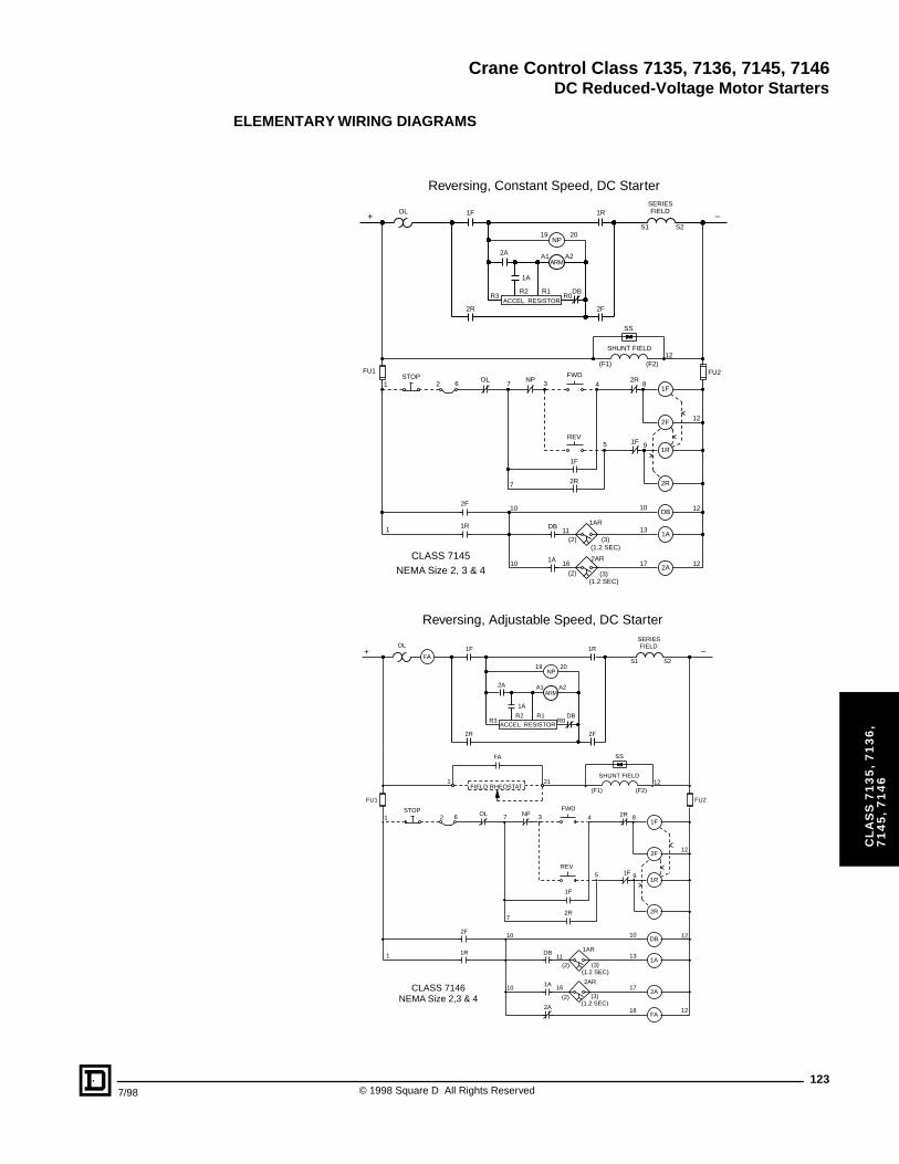
Crane Control Class 7135, 7136, 7145, 7146
DC Reduced-Voltage Motor Starters
7/98
CL
AS
S 7
13
5,
71
36
, 7
14
5,
71
46
ELEMENTARY WIRING DIAGRAMS
CLASS 7145
NEMA Size 2, 3 & 4
OL
2 6 7 3 4
7
5
(2) (3)
(3)(2)
STOP FWDNPOL
REV
1F
2R
ACCEL. RESISTOR
DB
1F
1A
NP19 20
1R
A1 A2
R0
2F
1F2R
SS
SHUNT FIELD
2F
1R
2R
1F
DB
8
9
10
16
2F
1R
10
10
1
FIELDSERIES
S1 S2
R1R3
FU1 FU2
12
2A
R2
ARM
1ADB
(1.2 SEC)
11 13
2A1A 17
12
2R
1AR
2AR
1
(F1) (F2)12
–+
(1.2 SEC)
12
Reversing, Constant Speed, DC Starter
Reversing, Adjustable Speed, DC Starter
CLASS 7146NEMA Size 2,3 & 4
OL
2 6 7 3 4
7
5
(2) (3)
(3)(2)
STOP FWDNPOL
REV
1F
2R
ACCEL. RESISTORDB
1F
1A
NP19 20
1R
A1 A2
R0
2F
1F2R
SS
SHUNT FIELD
2F
1R
2R
1F
DB
8
9
10
16
2F
1R
10
10
1
FIELDSERIES
S1 S2
R1R3
FU1 FU2
12
2A
R2
ARM
1ADB
(1.2 SEC)
11 13
2A1A 17
12
2R
1AR
2AR
1
(F1) (F2)12
–+FA
FA
2A(1.2 SEC)
12
FIELD RHEOSTAT
FA18
1 21
123© 1998 Square D All Rights Reserved
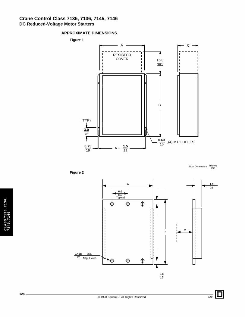
Crane Control Class 7135, 7136, 7145, 7146
DC Reduced-Voltage Motor Starters
124
CL
AS
S 7
13
5,
71
36
, 7
14
5,
71
46
APPROXIMATE DIMENSIONS
1.5
0.63
0.75
3.0
15.0
38
16,(4) MTG.HOLES
19
76
(TYP)
381
A +
RESISTORRESISTORCOVER
A
B
C
Figure 1
A
Dia.
Typical
Mtg. Holes
BC
6.0152
0.46812
1.025
0.615
Dual Dimensions inchesmm
Figure 2
© 1998 Square D All Rights Reserved 7/98
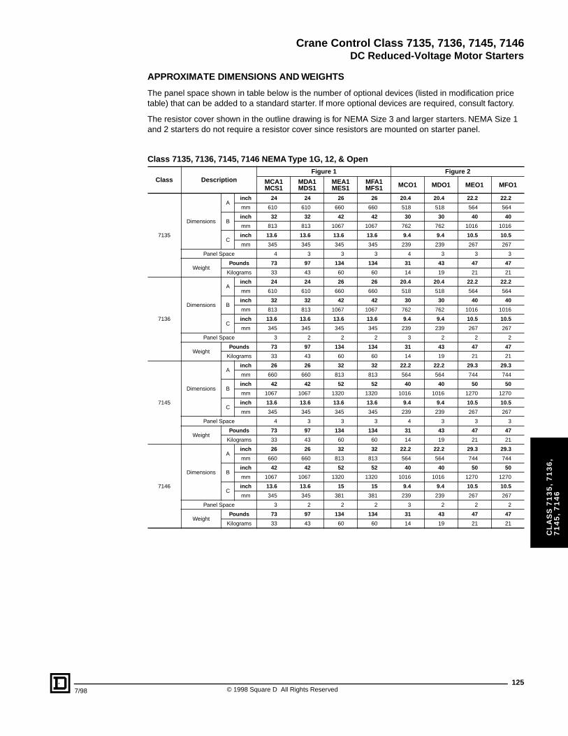
Crane Control Class 7135, 7136, 7145, 7146
DC Reduced-Voltage Motor Starters
7/98
CL
AS
S 7
13
5,
71
36
, 7
14
5,
71
46
APPROXIMATE DIMENSIONS AND WEIGHTS
The panel space shown in table below is the number of optional devices (listed in modification price table) that can be added to a standard starter. If more optional devices are required, consult factory.
The resistor cover shown in the outline drawing is for NEMA Size 3 and larger starters. NEMA Size 1 and 2 starters do not require a resistor cover since resistors are mounted on starter panel.
Class 7135, 7136, 7145, 7146 NEMA Type 1G, 12, & Open
Class DescriptionFigure 1 Figure 2
MCA1MCS1
MDA1MDS1
MEA1MES1
MFA1MFS1 MCO1 MDO1 MEO1 MFO1
7135
Dimensions
Ainch 24 24 26 26 20.4 20.4 22.2 22.2
mm 610 610 660 660 518 518 564 564
Binch 32 32 42 42 30 30 40 40
mm 813 813 1067 1067 762 762 1016 1016
Cinch 13.6 13.6 13.6 13.6 9.4 9.4 10.5 10.5
mm 345 345 345 345 239 239 267 267
Panel Space 4 3 3 3 4 3 3 3
WeightPounds 73 97 134 134 31 43 47 47
Kilograms 33 43 60 60 14 19 21 21
7136
Dimensions
Ainch 24 24 26 26 20.4 20.4 22.2 22.2
mm 610 610 660 660 518 518 564 564
Binch 32 32 42 42 30 30 40 40
mm 813 813 1067 1067 762 762 1016 1016
Cinch 13.6 13.6 13.6 13.6 9.4 9.4 10.5 10.5
mm 345 345 345 345 239 239 267 267
Panel Space 3 2 2 2 3 2 2 2
WeightPounds 73 97 134 134 31 43 47 47
Kilograms 33 43 60 60 14 19 21 21
7145
Dimensions
Ainch 26 26 32 32 22.2 22.2 29.3 29.3
mm 660 660 813 813 564 564 744 744
Binch 42 42 52 52 40 40 50 50
mm 1067 1067 1320 1320 1016 1016 1270 1270
Cinch 13.6 13.6 13.6 13.6 9.4 9.4 10.5 10.5
mm 345 345 345 345 239 239 267 267
Panel Space 4 3 3 3 4 3 3 3
WeightPounds 73 97 134 134 31 43 47 47
Kilograms 33 43 60 60 14 19 21 21
7146
Dimensions
Ainch 26 26 32 32 22.2 22.2 29.3 29.3
mm 660 660 813 813 564 564 744 744
Binch 42 42 52 52 40 40 50 50
mm 1067 1067 1320 1320 1016 1016 1270 1270
Cinch 13.6 13.6 15 15 9.4 9.4 10.5 10.5
mm 345 345 381 381 239 239 267 267
Panel Space 3 2 2 2 3 2 2 2
WeightPounds 73 97 134 134 31 43 47 47
Kilograms 33 43 60 60 14 19 21 21
125© 1998 Square D All Rights Reserved
Crane Control Class 7135, 7136, 7145, 7146
126
CL
AS
S 7
13
5,
71
36
, 7
14
5,
71
46
© 1998 Square D All Rights Reserved 7/98
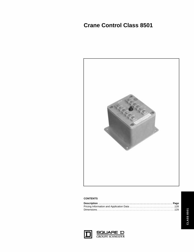
Crane Control Class 8501
50
1
CONTENTS
Description . . . . . . . . . . . . . . . . . . . . . . . . . . . . . . . . . . . . . . . . . . . . . . . . . . . . PagePricing Information and Application Data . . . . . . . . . . . . . . . . . . . . . . . . . . . . . . . .128Dimensions . . . . . . . . . . . . . . . . . . . . . . . . . . . . . . . . . . . . . . . . . . . . . . . . . . . . . . .129
CL
AS
S 8
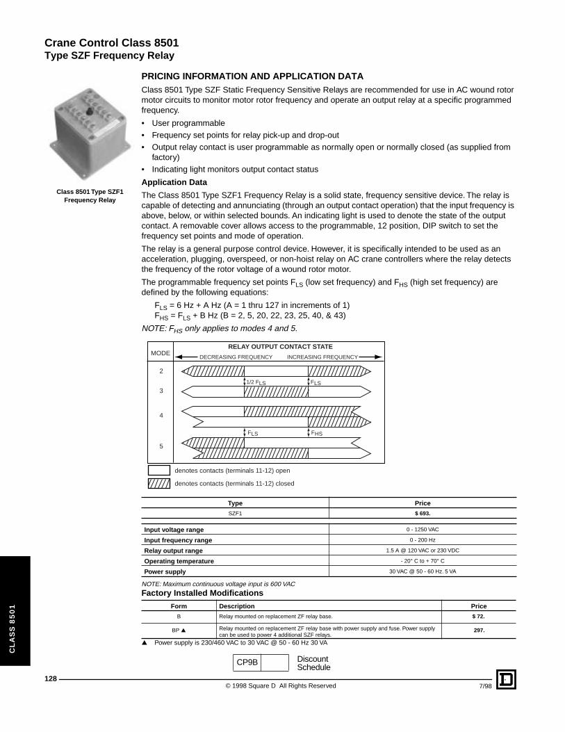
Crane Control Class 8501
Type SZF Frequency Relay
128
CL
AS
S 8
50
1
Class 8501 Type SZF1 Frequency Relay
PRICING INFORMATION AND APPLICATION DATAClass 8501 Type SZF Static Frequency Sensitive Relays are recommended for use in AC wound rotor motor circuits to monitor motor rotor frequency and operate an output relay at a specific programmed frequency.
• User programmable• Frequency set points for relay pick-up and drop-out• Output relay contact is user programmable as normally open or normally closed (as supplied from
factory)• Indicating light monitors output contact status
Application Data
The Class 8501 Type SZF1 Frequency Relay is a solid state, frequency sensitive device. The relay is capable of detecting and annunciating (through an output contact operation) that the input frequency is above, below, or within selected bounds. An indicating light is used to denote the state of the output contact. A removable cover allows access to the programmable, 12 position, DIP switch to set the frequency set points and mode of operation.
The relay is a general purpose control device. However, it is specifically intended to be used as an acceleration, plugging, overspeed, or non-hoist relay on AC crane controllers where the relay detects the frequency of the rotor voltage of a wound rotor motor.
The programmable frequency set points FLS (low set frequency) and FHS (high set frequency) are defined by the following equations:
FLS = 6 Hz + A Hz (A = 1 thru 127 in increments of 1)FHS = FLS + B Hz (B = 2, 5, 20, 22, 23, 25, 40, & 43)
NOTE: FHS only applies to modes 4 and 5.
NOTE: Maximum continuous voltage input is 600 VAC
▲ Power supply is 230/460 VAC to 30 VAC @ 50 - 60 Hz 30 VA
Type Price
SZF1 $ 693.
Input voltage range 0 - 1250 VAC
Input frequency range 0 - 200 Hz
Relay output range 1.5 A @ 120 VAC or 230 VDC
Operating temperature - 20° C to + 70° C
Power supply 30 VAC @ 50 - 60 Hz. 5 VA
Factory Installed Modifications
Form Description Price
B Relay mounted on replacement ZF relay base. $ 72.
BP ▲ Relay mounted on replacement ZF relay base with power supply and fuse. Power supply can be used to power 4 additional SZF relays.
297.
MODE
2
3
4
5
denotes contacts (terminals 11-12) open
denotes contacts (terminals 11-12) closed
DECREASING FREQUENCY
1/2 FLS FLS
FHSFLS
INCREASING FREQUENCY
RELAY OUTPUT CONTACT STATE
CP9B DiscountSchedule
© 1998 Square D All Rights Reserved 7/98
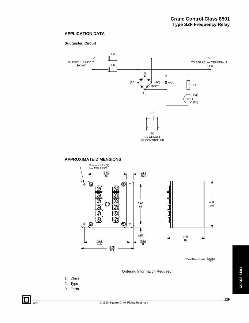
Crane Control Class 8501
Type SZF Frequency Relay
7/98
CL
AS
S 8
50
1
APPLICATION DATA
Suggested Circuit
APPROXIMATE DIMENSIONS
Ordering Information Required:
1. Class2. Type3. Form
TOUV CIRCUIT
OF CONTROLLER
30 VACTO SZF RELAY TERMINALS
7 & 8
SRP
MOV
(+)
(AC) (AC)
(–)
RECT RES
FU
FU
SRP
(A1)
(A2)
TO POWER SUPPLY
105
16.3
93 109
878
8
89
121
4.15
0.64
3.65 4.28
3.430.32
0.32
3.50
4.78
Clearance for (4)#10 mtg. screw
Dual Dimensions inchesmm
129© 1998 Square D All Rights Reserved
Crane Control Class 8501
130
CL
AS
S 8
50
1
© 1998 Square D All Rights Reserved 7/98
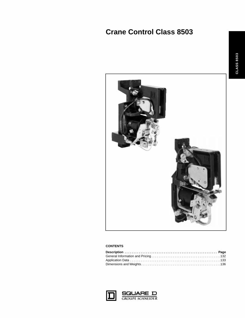
Crane Control Class 8503
CL
AS
S 8
50
3
CONTENTS
Description . . . . . . . . . . . . . . . . . . . . . . . . . . . . . . . . . . . . . . . . . . . . . . . . . . . . PageGeneral Information and Pricing . . . . . . . . . . . . . . . . . . . . . . . . . . . . . . . . . . . . . . .132Application Data . . . . . . . . . . . . . . . . . . . . . . . . . . . . . . . . . . . . . . . . . . . . . . . . . . .133Dimensions and Weights. . . . . . . . . . . . . . . . . . . . . . . . . . . . . . . . . . . . . . . . . . . . .136
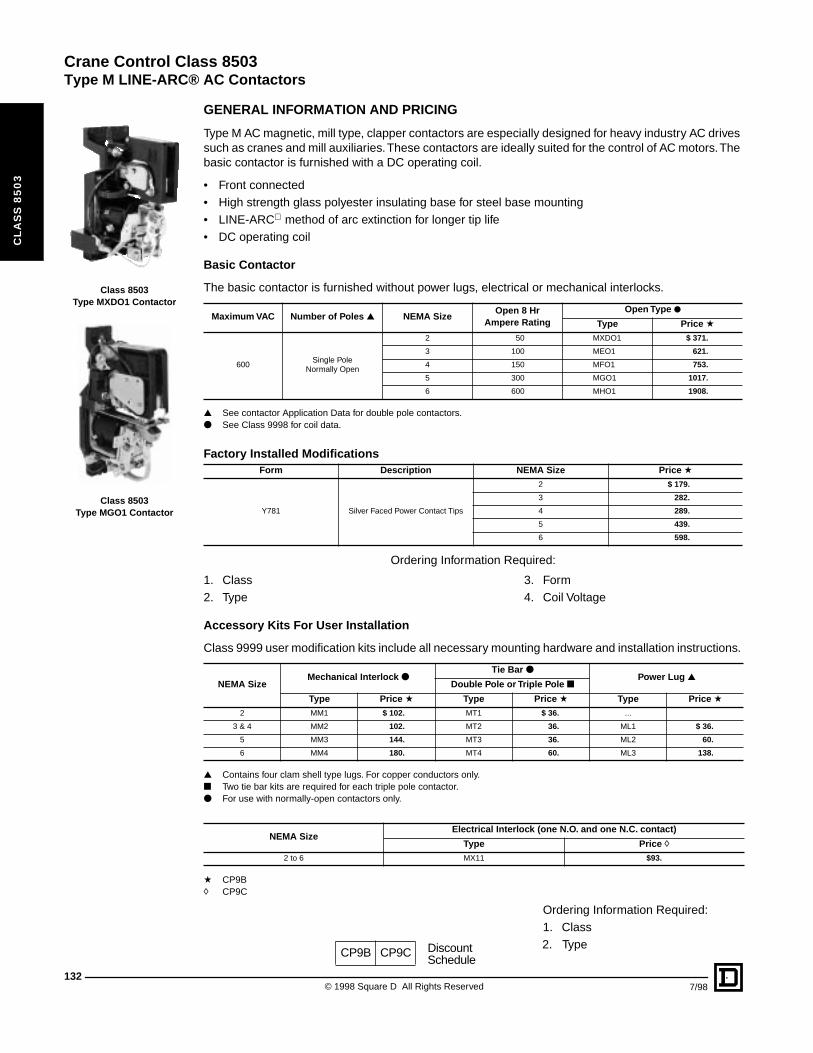
Crane Control Class 8503
Type M LINE-ARC® AC Contactors
132
CL
AS
S 8
50
3
Class 8503 Type MXDO1 Contactor
Class 8503Type MGO1 Contactor
© 1998 Square D All Rights Reserved 7/98
GENERAL INFORMATION AND PRICING
Type M AC magnetic, mill type, clapper contactors are especially designed for heavy industry AC drives such as cranes and mill auxiliaries. These contactors are ideally suited for the control of AC motors. The basic contactor is furnished with a DC operating coil.
• Front connected• High strength glass polyester insulating base for steel base mounting• LINE-ARC method of arc extinction for longer tip life• DC operating coil
Basic Contactor
The basic contactor is furnished without power lugs, electrical or mechanical interlocks.
▲ See contactor Application Data for double pole contactors.● See Class 9998 for coil data.
Ordering Information Required:
1. Class 3. Form2. Type 4. Coil Voltage
Accessory Kits For User Installation
Class 9999 user modification kits include all necessary mounting hardware and installation instructions.
▲ Contains four clam shell type lugs. For copper conductors only.■ Two tie bar kits are required for each triple pole contactor.● For use with normally-open contactors only.
a CP9B h CP9C
Ordering Information Required:1. Class2. Type
Maximum VAC Number of Poles ▲ NEMA SizeOpen 8 Hr
Ampere RatingOpen Type ●
Type Price a
600Single Pole
Normally Open
2 50 MXDO1 $ 371.
3 100 MEO1 621.
4 150 MFO1 753.
5 300 MGO1 1017.
6 600 MHO1 1908.
Factory Installed ModificationsForm Description NEMA Size Price a
Y781 Silver Faced Power Contact Tips
2 $ 179.
3 282.
4 289.
5 439.
6 598.
NEMA SizeMechanical Interlock ●
Tie Bar ●Power Lug ▲
Double Pole or Triple Pole ■
Type Price a Type Price a Type Price a2 MM1 $ 102. MT1 $ 36. ...
3 & 4 MM2 102. MT2 36. ML1 $ 36.
5 MM3 144. MT3 36. ML2 60.
6 MM4 180. MT4 60. ML3 138.
NEMA SizeElectrical Interlock (one N.O. and one N.C. contact)
Type Price h2 to 6 MX11 $93.
CP9B CP9C DiscountSchedule
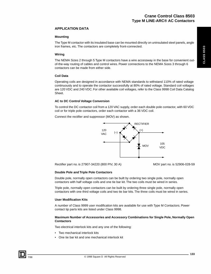
Crane Control Class 8503
Type M LINE-ARC® AC Contactors
7/98
CL
AS
S 8
50
3
APPLICATION DATA
Mounting
The Type M contactor with its insulated base can be mounted directly on uninsulated steel panels, angle iron frames, etc. The contactors are completely front-connected.
Wiring
The NEMA Sizes 2 through 5 Type M contactors have a wire accessway in the base for convenient out-of-the-way routing of cables and control wires. Power connections to the NEMA Sizes 3 through 6 contactors can be made from either side.
Coil Data
Operating coils are designed in accordance with NEMA standards to withstand 110% of rated voltage continuously and to operate the contactor successfully at 80% of rated voltage. Standard coil voltages are 120 VDC and 240 VDC. For other available coil voltages, refer to the Class 9998 Coil Data Catalog Sheet.
AC to DC Control Voltage Conversion
To control the DC contactor coil from a 120 VAC supply, order each double pole contactor, with 60 VDC coil or for triple pole contactors, order each contactor with a 36 VDC coil.
Connect the rectifier and suppressor (MOV) as shown.
Rectifier part no. is 27907-34220 (800 PIV, 30 A) MOV part no. is 52906-028-59
Double Pole and Triple Pole Contactors
Double pole, normally open contactors can be built by ordering two single pole, normally open contactors with half voltage coils and one tie bar kit. The two coils must be wired in series.
Triple pole, normally open contactors can be built by ordering three single pole, normally open contactors with one third voltage coils and two tie bar kits. The three coils must be wired in series.
User Modification Kits
A number of Class 9999 user modification kits are available for use with Type M Contactors. Power contact tip parts kits are listed under Class 9998.
Maximum Number of Accessories and Accessory Combinations for Single Pole, Normally Open Contactors
Two electrical interlock kits and any one of the following:
• Two mechanical interlock kits• One tie bar kit and one mechanical interlock kit
(+)(–)
RECTIFIER
MOV
120
105
VAC
VDC
133© 1998 Square D All Rights Reserved
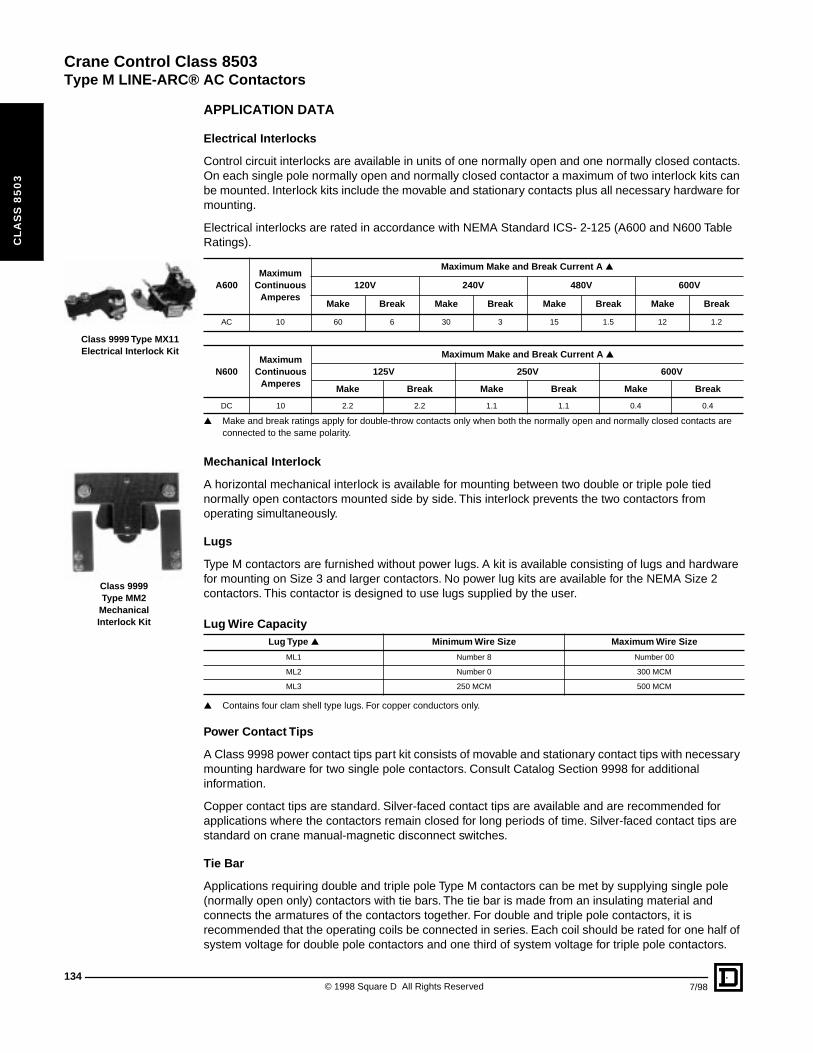
Crane Control Class 8503
Type M LINE-ARC® AC Contactors
134
CL
AS
S 8
50
3
Class 9999 Type MX11Electrical Interlock Kit
Class 9999Type MM2
MechanicalInterlock Kit
APPLICATION DATA
Electrical Interlocks
Control circuit interlocks are available in units of one normally open and one normally closed contacts. On each single pole normally open and normally closed contactor a maximum of two interlock kits can be mounted. Interlock kits include the movable and stationary contacts plus all necessary hardware for mounting.
Electrical interlocks are rated in accordance with NEMA Standard ICS- 2-125 (A600 and N600 Table Ratings).
▲ Make and break ratings apply for double-throw contacts only when both the normally open and normally closed contacts are connected to the same polarity.
Mechanical Interlock
A horizontal mechanical interlock is available for mounting between two double or triple pole tied normally open contactors mounted side by side. This interlock prevents the two contactors from operating simultaneously.
Lugs
Type M contactors are furnished without power lugs. A kit is available consisting of lugs and hardware for mounting on Size 3 and larger contactors. No power lug kits are available for the NEMA Size 2 contactors. This contactor is designed to use lugs supplied by the user.
▲ Contains four clam shell type lugs. For copper conductors only.
Power Contact Tips
A Class 9998 power contact tips part kit consists of movable and stationary contact tips with necessary mounting hardware for two single pole contactors. Consult Catalog Section 9998 for additional information.
Copper contact tips are standard. Silver-faced contact tips are available and are recommended for applications where the contactors remain closed for long periods of time. Silver-faced contact tips are standard on crane manual-magnetic disconnect switches.
Tie Bar
Applications requiring double and triple pole Type M contactors can be met by supplying single pole (normally open only) contactors with tie bars. The tie bar is made from an insulating material and connects the armatures of the contactors together. For double and triple pole contactors, it is recommended that the operating coils be connected in series. Each coil should be rated for one half of system voltage for double pole contactors and one third of system voltage for triple pole contactors.
A600Maximum
Continuous Amperes
Maximum Make and Break Current A ▲
120V 240V 480V 600V
Make Break Make Break Make Break Make Break
AC 10 60 6 30 3 15 1.5 12 1.2
N600Maximum
Continuous Amperes
Maximum Make and Break Current A ▲
125V 250V 600V
Make Break Make Break Make Break
DC 10 2.2 2.2 1.1 1.1 0.4 0.4
Lug Wire CapacityLug Type ▲ Minimum Wire Size Maximum Wire Size
ML1 Number 8 Number 00
ML2 Number 0 300 MCM
ML3 250 MCM 500 MCM
© 1998 Square D All Rights Reserved 7/98
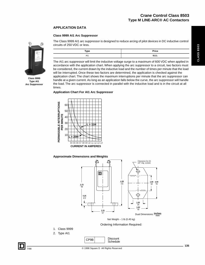
Crane Control Class 8503
Type M LINE-ARC® AC Contactors
7/98
CL
AS
S 8
50
3
Class 9999Type AI1
Arc Suppressor
APPLICATION DATA
Class 9999 AI1 Arc Suppressor
The Class 9999 AI1 arc suppressor is designed to reduce arcing of pilot devices in DC inductive control circuits of 250 VDC or less.
The AI1 arc suppressor will limit the inductive voltage surge to a maximum of 600 VDC when applied in accordance with the application chart. When applying the arc suppressor to a circuit, two factors must be considered, the current drawn by the inductive load and the number of times per minute that the load will be interrupted. Once these two factors are determined, the application is checked against the application chart. The chart shows the maximum interruptions per minute that the arc suppressor can handle at a given current. As long as an application falls below the curve, the arc suppressor will handle the load. The arc suppressor is connected in parallel with the inductive load and is in the circuit at all times.
Application Chart For AI1 Arc Suppressor
Approximate Dimensions and Weights
Ordering Information Required:1. Class 99992. Type AI1
Type Price
AI1 $111.
10
CURRENT IN AMPERES
PE
RM
ISS
IBL
E IN
TE
RR
UP
TIO
NS
PE
R M
INU
TE
0.4 0.5 0.6 0.7 0.8 0.9 1.0 1.1 1.2 1.3 1.4
20
30
40
50
60
L = 11H
L = 20H
Net Weight - 1lb
57
111
25
49
42 76
6.3
95
2.25
4.38
1.00
1.93
1.65 3.00
0.25
3.75
Clearance for (2)1/4" mtg. screws
mmDual Dimensions: inches
Net Weight – 1 lb (0.45 kg)
CP9B DiscountSchedule
135© 1998 Square D All Rights Reserved
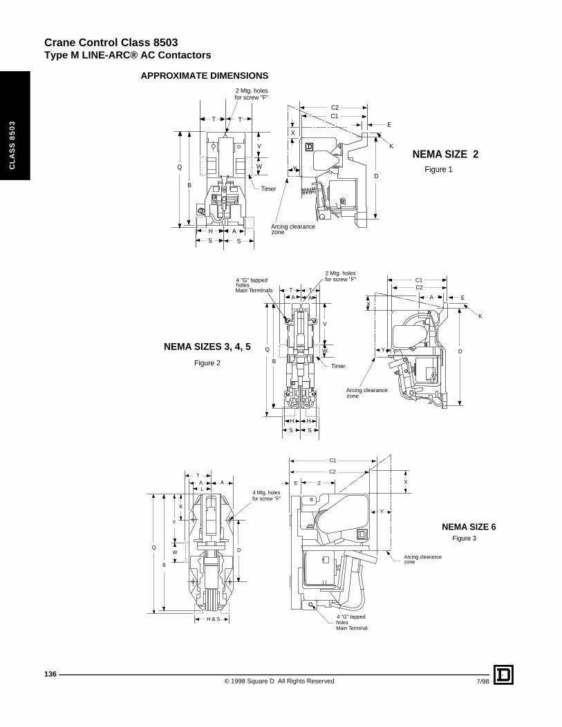
Crane Control Class 8503
Type M LINE-ARC® AC Contactors
136
CL
AS
S 8
50
3
APPROXIMATE DIMENSIONS
K
E
D
C2C1
X
Y
Timer
Arcing clearancezone
2 Mtg. holesfor screw "F"
T T
V
WQ
B
H A
S S
Figure 1
NEMA SIZE 2
C1C2
A E
K
D
X
Y
Arcing clearancezone
for screw "F"2 Mtg. holes
Timer
Main Terminalsholes4 "G" tapped
T TAA
V
WQ
B
H H
S S
Figure 2
NEMA SIZES 3, 4, 5
C1
C2
E Z X
Y
Arcing clearancezone
Figure 3
NEMA SIZE 6
4 "G" tappedholesMain Terminal
for screw "F"4 Mtg. holes
TA AL
K
Y
WQ D
H & S
B
© 1998 Square D All Rights Reserved 7/98
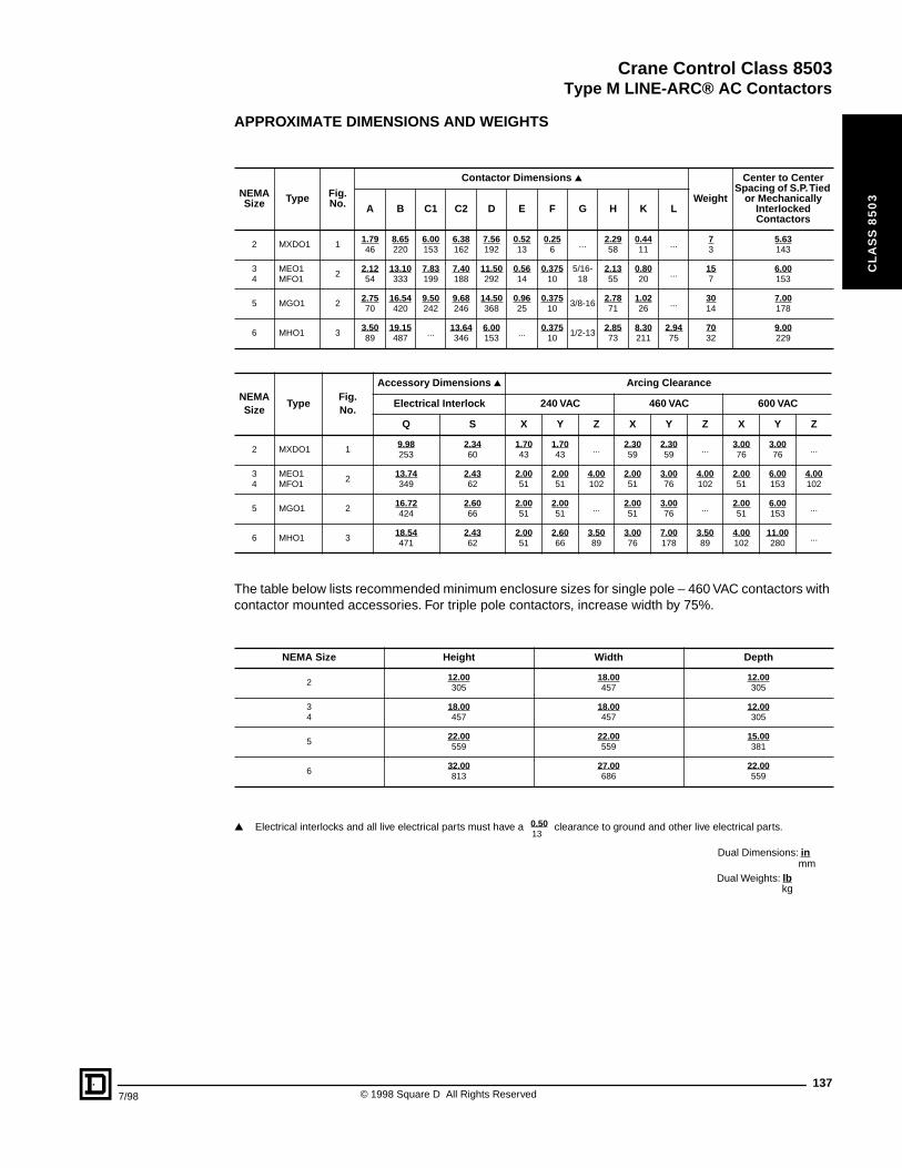
Crane Control Class 8503
Type M LINE-ARC® AC Contactors
7/98
CL
AS
S 8
50
3
APPROXIMATE DIMENSIONS AND WEIGHTS
The table below lists recommended minimum enclosure sizes for single pole – 460 VAC contactors with contactor mounted accessories. For triple pole contactors, increase width by 75%.
▲ Electrical interlocks and all live electrical parts must have a clearance to ground and other live electrical parts.
NEMASize Type Fig.
No.
Contactor Dimensions ▲
Weight
Center to Center Spacing of S.P. Tied
or Mechanically Interlocked Contactors
A B C1 C2 D E F G H K L
2 MXDO1 11.7946
8.65220
6.00153
6.38162
7.56192
0.5213
0.256
...2.2958
0.4411
...73
5.63143
34
MEO1MFO1
22.1254
13.10333
7.83199
7.40188
11.50292
0.5614
0.37510
5/16-18
2.1355
0.8020
...157
6.00153
5 MGO1 22.7570
16.54420
9.50242
9.68246
14.50368
0.9625
0.37510
3/8-162.7871
1.0226
...3014
7.00178
6 MHO1 33.5089
19.15487
...13.64346
6.00153
...0.375
101/2-13
2.8573
8.30211
2.9475
7032
9.00229
NEMASize
TypeFig.No.
Accessory Dimensions ▲ Arcing Clearance
Electrical Interlock 240 VAC 460 VAC 600 VAC
Q S X Y Z X Y Z X Y Z
2 MXDO1 19.98253
2.3460
1.7043
1.7043
...2.3059
2.3059
...3.0076
3.0076
...
34
MEO1MFO1
213.74349
2.4362
2.0051
2.0051
4.00102
2.0051
3.0076
4.00102
2.0051
6.00153
4.00102
5 MGO1 216.72424
2.6066
2.0051
2.0051
...2.0051
3.0076
...2.0051
6.00153
...
6 MHO1 318.54471
2.4362
2.0051
2.6066
3.5089
3.0076
7.00178
3.5089
4.00102
11.00280
...
NEMA Size Height Width Depth
212.00305
18.00457
12.00305
34
18.00457
18.00457
12.00305
522.00559
22.00559
15.00381
632.00813
27.00686
22.00559
130.50
Dual Weights: lb
Dual Dimensions: inmm
kg
137© 1998 Square D All Rights Reserved
Crane Control Class 8503
138
CL
AS
S 8
50
3
© 1998 Square D All Rights Reserved 7/98
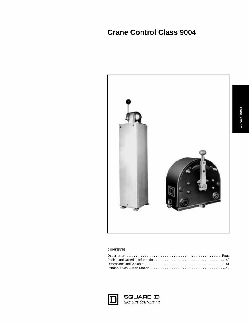
Crane Control Class 9004
CL
AS
S 9
00
4
CONTENTS
Description . . . . . . . . . . . . . . . . . . . . . . . . . . . . . . . . . . . . . . . . . . . . . . . . . . . . PagePricing and Ordering Information . . . . . . . . . . . . . . . . . . . . . . . . . . . . . . . . . . . . . .140Dimensions and Weights. . . . . . . . . . . . . . . . . . . . . . . . . . . . . . . . . . . . . . . . . . . . .141Pendant Push Button Station . . . . . . . . . . . . . . . . . . . . . . . . . . . . . . . . . . . . . . . . .143
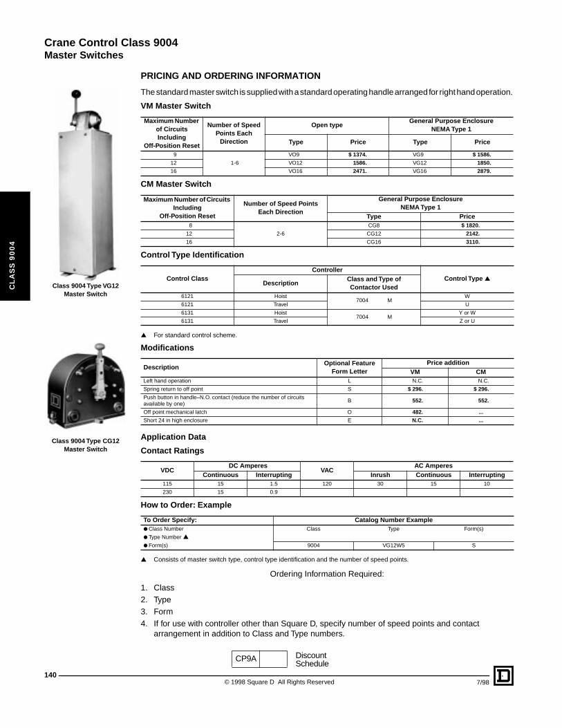
Crane Control Class 9004
Master Switches
140
CL
AS
S 9
00
4
Class 9004 Type VG12 Master Switch
Class 9004 Type CG12 Master Switch
PRICING AND ORDERING INFORMATION
The standard master switch is supplied with a standard operating handle arranged for right hand operation.
▲ For standard control scheme.
Application Data
▲ Consists of master switch type, control type identification and the number of speed points.
Ordering Information Required:
1. Class2. Type 3. Form4. If for use with controller other than Square D, specify number of speed points and contact
arrangement in addition to Class and Type numbers.
VM Master Switch
Maximum Number of Circuits Including
Off-Position Reset
Number of Speed Points Each
Direction
Open typeGeneral Purpose Enclosure
NEMA Type 1
Type Price Type Price
9
1-6
VO9 $ 1374. VG9 $ 1586.
12 VO12 1586. VG12 1850.
16 VO16 2471. VG16 2879.
CM Master Switch
Maximum Number of Circuits Including
Off-Position Reset
Number of Speed Points Each Direction
General Purpose EnclosureNEMA Type 1
Type Price8
2-6
CG8 $ 1820.
12 CG12 2142.
16 CG16 3110.
Control Type Identification
Control ClassController
Control Type ▲Description
Class and Type of Contactor Used
6121 Hoist7004 M
W
6121 Travel U
6131 Hoist7004 M
Y or W
6131 Travel Z or U
Modifications
DescriptionOptional Feature
Form LetterPrice addition
VM CMLeft hand operation L N.C. N.C.
Spring return to off point S $ 296. $ 296.
Push button in handle–N.O. contact (reduce the number of circuits available by one)
B 552. 552.
Off point mechanical latch O 482. ...
Short 24 in high enclosure E N.C. ...
Contact Ratings
VDC DC Amperes
VACAC Amperes
Continuous Interrupting Inrush Continuous Interrupting115 15 1.5 120 30 15 10
230 15 0.9
How to Order: Example
To Order Specify: Catalog Number Example● Class Number Class Type Form(s)
● Type Number ▲
● Form(s) 9004 VG12W5 S
CP9A DiscountSchedule
© 1998 Square D All Rights Reserved 7/98
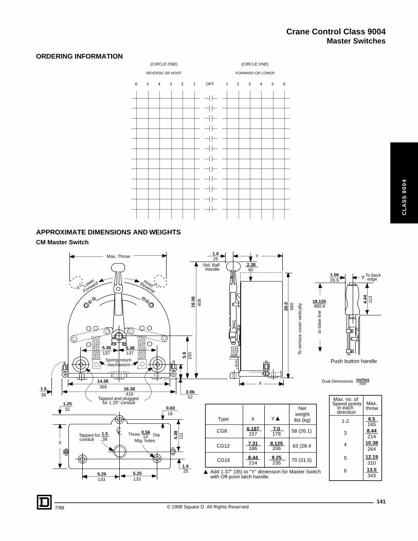
Crane Control Class 9004
Master Switches
CL
AS
S 9
00
4
ORDERING INFORMATION
APPROXIMATE DIMENSIONS AND WEIGHTSCM Master Switch
OFF1 16 65 54 43 32 2
REVERSE OR HOIST FORWARD OR LOWER
(CIRCLE ONE) (CIRCLE ONE)
Push button handle
1.0626.9 Y To back
edge
4.44
113
18.125460.4
to b
ase
line
X
Y1.025
2.3860
Std. BallHandle
To r
emov
e co
ver
vert
ical
ly
26.0
66016
.06
408
Max. Throw
Lower
ForwardHoistReverse
5.38 5.38137 137
5.9
150
2.0652
0.6316
Spring returnmechanism
1.538
14.38
16.38365
416Tapped and plugged
for 1.25" conduit1.2532
X
4.38
111
1.025
5.25 5.25133 133
0.5614
1.538
Tapped forconduit
Three Dia.Mtg. holes
Type X Y
Netweightlbs (kg)
CG8 6.187157
7.0178
7.31186
8.44214
8.125206
9.25235
58 (26.1)
63 (28.4
70 (31.5)
CG12
CG16
Add 1.37" (35) to "Y" dimension for Master Switchwith Off-point latch handle.
Max. no. ofSpeed points
in eachdirection
Max.throw
1-2
3
4
5
6
6.51658.44214
10.38264
12.1931013.5343
Dual Dimensions inchesmm
1417/98 © 1998 Square D All Rights Reserved
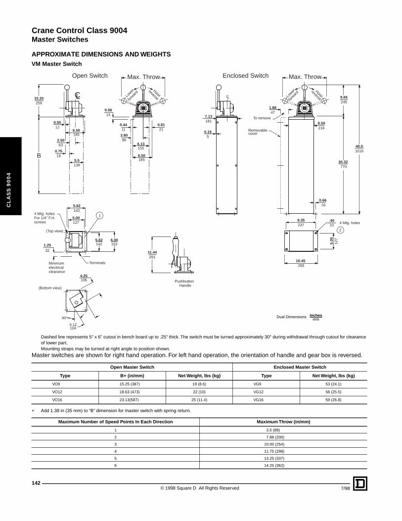
Crane Control Class 9004
Master Switches
CL
AS
S 9
00
4
APPROXIMATE DIMENSIONS AND WEIGHTSVM Master Switch
Dashed line represents 5" x 6" cutout in bench board up to .25" thick. The switch must be turned approximately 30° during withdrawal through cutout for clearance of lower part. Mounting straps may be turned at right angle to position shown.
Master switches are shown for right hand operation. For left hand operation, the orientation of handle and gear box is reversed.
+ Add 1.38 in (35 mm) to “B” dimension for master switch with spring return.
Open Master Switch Enclosed Master Switch
Type B+ (in/mm) Net Weight, lbs (kg) Type Net Weight, lbs (kg)
VO9 15.25 (387) 19 (8.6) VG9 53 (24.1)
VO12 18.63 (473) 22 (10) VG12 56 (25.5)
VO16 23.13(587) 25 (11.4) VG16 59 (26.8)
Maximum Number of Speed Points In Each Direction Maximum Throw (in/mm)
1 3.5 (89)
2 7.88 (200)
3 10.00 (254)
4 11.75 (298)
5 13.25 (337)
6 14.25 (362)
1
2
Lower
Lower Hoist
Hoistfo
rwar
d
forw
ard reverse
reverse
Minimum
clearance
Handle
electrical
Pushbutton
C
(Top view)
(Bottom view)
L LC
Max. ThrowMax. Throw
5.00
127
9.35237 4 Mtg. holes
0.66 16
10.45 265
9.65245
30.32 770
40.01016
Removable
To remove
cover
7.13181 8.50
216
5.00127
6.00152
5.62142
5.62142
Terminals
1.2532
4 Mtg. holesFor 1/4" F.H.screws
4.25106
4.12104
30°
10.20259
0.5614
3.8096
0.4411
6.13155
0.8121
6.50165
2.5063
0.195
0.5012
6.50165
0.7519
5.5139
11.44291
1.8847
.4010
B
Enclosed SwitchOpen Switch
Dual Dimensions inchesmm
© 1998 Square D All Rights Reserved142
7/98
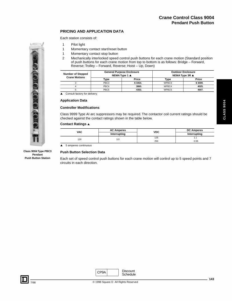
Crane Control Class 9004
Pendant Push Button
7/98
CL
AS
S 9
00
4
Class 9004 Type PBC3 Pendant
Push Button Station
PRICING AND APPLICATION DATA
Each station consists of:
1 Pilot light1 Momentary contact start/reset button1 Momentary contact stop button2 Mechanically interlocked speed control push buttons for each crane motion (Standard position
of push buttons for each crane motion from top to bottom is as follows: Bridge – Forward, Reverse; Trolley – Forward, Reverse; Hoist – Up, Down)
▲ Consult factory for delivery.
Application Data
Controller Modifications
Class 9999 Type AI arc suppressors may be required. The contactor coil current ratings should be checked against the contact ratings shown in the table below.
▲ 5 amperes continuous
Push Button Selection Data
Each set of speed control push buttons for each crane motion will control up to 5 speed points and 7 circuits in each direction.
Number of Stepped Crane Motions
General Purpose Enclosure NEMA Type 1 ▲
Outdoor EnclosureNEMA Type 3R ▲
Type Price Type Price3 PBC3 $ 3454. WPBC3 $ 3590.
4 PBC4 3860. WPBC4 4025.
5 PBC5 4353. WPBC5 4607.
Contact Ratings ▲
VACAC Amperes
VDCDC Amperes
Interrupting Interrupting
120 3.0125 1.1
250 0.55
CP9A DiscountSchedule
143© 1998 Square D All Rights Reserved
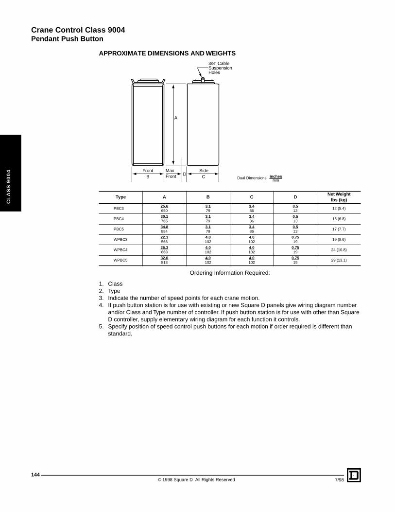
Crane Control Class 9004
Pendant Push Button
144
CL
AS
S 9
00
4
APPROXIMATE DIMENSIONS AND WEIGHTS
Ordering Information Required:
1. Class2. Type 3. Indicate the number of speed points for each crane motion.4. If push button station is for use with existing or new Square D panels give wiring diagram number
and/or Class and Type number of controller. If push button station is for use with other than Square D controller, supply elementary wiring diagram for each function it controls.
5. Specify position of speed control push buttons for each motion if order required is different than standard.
Type A B C DNet Weight
lbs (kg)
PBC325.6650
3.179
3.486
0.513
12 (5.4)
PBC430.1765
3.179
3.486
0.513
15 (6.8)
PBC534.8884
3.179
3.486
0.513
17 (7.7)
WPBC322.3566
4.0102
4.0102
0.7519
19 (8.6)
WPBC426.3668
4.0102
4.0102
0.7519
24 (10.8)
WPBC532.0813
4.0102
4.0102
0.7519
29 (13.1)
3/8" CableSuspensionHoles
A
DBFront Max
Front CSide
Dual Dimensions inchesmm
© 1998 Square D All Rights Reserved 7/98
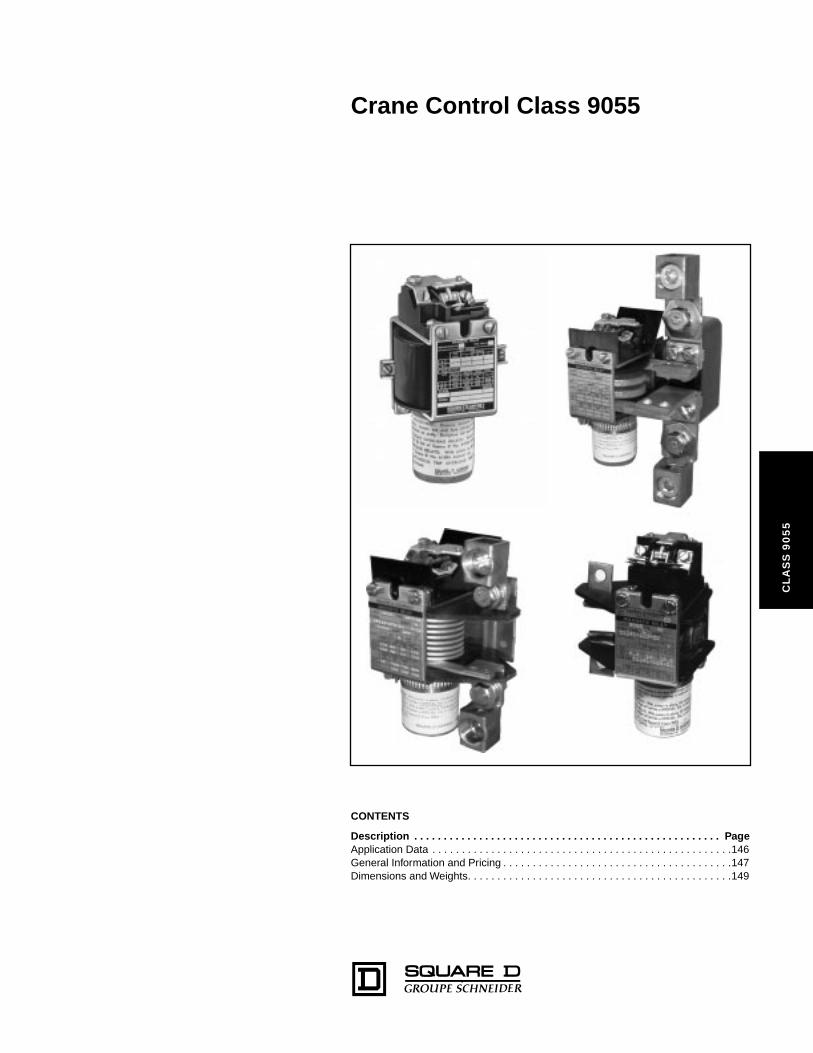
Crane Control Class 9055
CL
AS
S 9
05
5
CONTENTS
Description . . . . . . . . . . . . . . . . . . . . . . . . . . . . . . . . . . . . . . . . . . . . . . . . . . . . PageApplication Data . . . . . . . . . . . . . . . . . . . . . . . . . . . . . . . . . . . . . . . . . . . . . . . . . . .146General Information and Pricing . . . . . . . . . . . . . . . . . . . . . . . . . . . . . . . . . . . . . . .147Dimensions and Weights. . . . . . . . . . . . . . . . . . . . . . . . . . . . . . . . . . . . . . . . . . . . .149
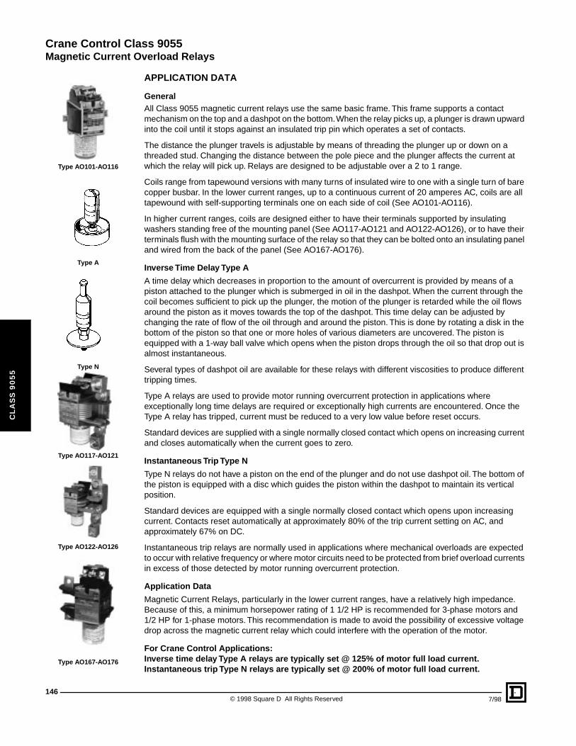
Crane Control Class 9055
Magnetic Current Overload Relays
146
CL
AS
S 9
05
5
Type AO101-AO116
Type A
Type N
Type AO117-AO121
Type AO122-AO126
Type AO167-AO176
APPLICATION DATA
GeneralAll Class 9055 magnetic current relays use the same basic frame. This frame supports a contact mechanism on the top and a dashpot on the bottom. When the relay picks up, a plunger is drawn upward into the coil until it stops against an insulated trip pin which operates a set of contacts.
The distance the plunger travels is adjustable by means of threading the plunger up or down on a threaded stud. Changing the distance between the pole piece and the plunger affects the current at which the relay will pick up. Relays are designed to be adjustable over a 2 to 1 range.
Coils range from tapewound versions with many turns of insulated wire to one with a single turn of bare copper busbar. In the lower current ranges, up to a continuous current of 20 amperes AC, coils are all tapewound with self-supporting terminals one on each side of coil (See AO101-AO116).
In higher current ranges, coils are designed either to have their terminals supported by insulating washers standing free of the mounting panel (See AO117-AO121 and AO122-AO126), or to have their terminals flush with the mounting surface of the relay so that they can be bolted onto an insulating panel and wired from the back of the panel (See AO167-AO176).
Inverse Time Delay Type A
A time delay which decreases in proportion to the amount of overcurrent is provided by means of a piston attached to the plunger which is submerged in oil in the dashpot. When the current through the coil becomes sufficient to pick up the plunger, the motion of the plunger is retarded while the oil flows around the piston as it moves towards the top of the dashpot. This time delay can be adjusted by changing the rate of flow of the oil through and around the piston. This is done by rotating a disk in the bottom of the piston so that one or more holes of various diameters are uncovered. The piston is equipped with a 1-way ball valve which opens when the piston drops through the oil so that drop out is almost instantaneous.
Several types of dashpot oil are available for these relays with different viscosities to produce different tripping times.
Type A relays are used to provide motor running overcurrent protection in applications where exceptionally long time delays are required or exceptionally high currents are encountered. Once the Type A relay has tripped, current must be reduced to a very low value before reset occurs.
Standard devices are supplied with a single normally closed contact which opens on increasing current and closes automatically when the current goes to zero.
Instantaneous Trip Type N
Type N relays do not have a piston on the end of the plunger and do not use dashpot oil. The bottom of the piston is equipped with a disc which guides the piston within the dashpot to maintain its vertical position.
Standard devices are equipped with a single normally closed contact which opens upon increasing current. Contacts reset automatically at approximately 80% of the trip current setting on AC, and approximately 67% on DC.
Instantaneous trip relays are normally used in applications where mechanical overloads are expected to occur with relative frequency or where motor circuits need to be protected from brief overload currents in excess of those detected by motor running overcurrent protection.
Application Data
Magnetic Current Relays, particularly in the lower current ranges, have a relatively high impedance. Because of this, a minimum horsepower rating of 1 1/2 HP is recommended for 3-phase motors and 1/2 HP for 1-phase motors. This recommendation is made to avoid the possibility of excessive voltage drop across the magnetic current relay which could interfere with the operation of the motor.
For Crane Control Applications:Inverse time delay Type A relays are typically set @ 125% of motor full load current.Instantaneous trip Type N relays are typically set @ 200% of motor full load current.
© 1998 Square D All Rights Reserved 7/98
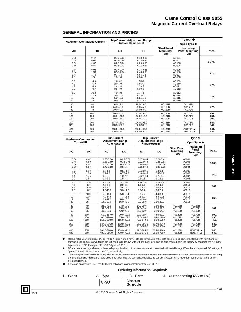
Crane Control Class 9055
Magnetic Current Overload Relays
7/98
CL
AS
S 9
05
5
GENERAL INFORMATION AND PRICING
● Relays rated 32 A and above (A, or NO 117R and higher) have both coil terminals on the right hand side as standard. Relays with right hand coil terminals can be field converted to the left hand side. Relays with left hand coil terminals can be ordered from the factory by changing the “R” in the type number to “L”. Example: Class 9055 Type NO 117L.
▲ DC continuous ratings shown for these relays apply when coil terminals are front connected with suitable lugs. When back connected, DC ratings of Types 175 and 176 are 420 and 640 A, respectively.
■ These relays should normally be adjusted to trip at a current value less than the listed maximum continuous current. In special applications requiring the use of a higher trip setting, care should be taken that the coil is not subjected to current in excess of its maximum continuous rating for any prolonged period.
◆ For crane applications use Type C2U dashpot oil and dashpot locking strap 750D107G1.
Ordering Information Required:
1. Class 2. Type 3. Form 4. Current setting (AC or DC)
Maximum Continuous Current Trip Current Adjustment Range Auto or Hand Reset
Type A ◆
Open Type ●
Steel Panel Mounting
Type
Insulating Panel Mounting
TypePriceAC DC AC DC
0.380.480.540.70
0.470.600.670.87
0.19-0.380.24-0.480.27-0.540.35-0.70
0.18-0.350.23-0.450.25-0.500.32-0.64
AO101AO102AO103AO104
$ 272.
0.741.041.42.0
0.921.301.752.5
0.37-0.740.52-1.040.7-1.41.0-2.0
0.34-0.680.48-0.960.65-1.30.93-1.8
AO105AO106AO107AO108
272.
3.24.04.87.0
4.05.06.08.7
1.6-3.22.0-4.02.4-4.83.5-7.0
1.5-3.01.8-3.72.2-4.53.3-6.5
AO109AO110AO111AO112
272.
8.0101220
10.012.51525
4.0-8.05.0-10.06.0-12.0
10.0-20.0
3.7-7.54.7-9.35.6-11.19.3-18.6
AO113AO114AO115AO116
272.
324860
406075
16.0-32.024.0-48.030.0-60.0
15.0-30.022.0-45.028.0-56.0
AO117RAO118RAO119R
AO167RAO168RAO169R
272.
80120160
100150200
40.0-80.060.0-120.080.0-160.0
37.0-75.056.0-110.075.0-150.0
AO120RAO121RAO122R
AO170RAO171RAO172R
293.293.396.
210320
260400
107.0-210.0160.0-320.0
100.0-195.0150.0-300.0
AO123RAO124R
AO173RAO174R
840.840.
420640
525800
210.0-420.0320.0-640.0
200.0-400.0300.0-600.0
AO125RAO126R
AO175R ▲AO176R ▲
840.840.
Maximum Continuous Current ■
Trip CurrentAdjustment Range
Auto Reset ■
Trip Current Adjustment Range
Hand Reset ■
Type N
Open Type ●
Steel Panel Mounting
Type
Insulating Panel
MountingType
PriceAC DC AC DC AC DC
0.380.480.540.70
0.470.600.670.87
0.26-0.540.33-0.690.36-0.760.47-0.98
0.27-0.600.35-0.760.38-0.840.5-1.1
0.17-0.340.22-0.440.24-0.480.31-0.62
0.21-0.410.26-0.530.29-0.580.38-0.75
NO101NO102NO103NO104
$ 269.
0.741.041.42.0
0.921.301.752.5
0.5-1.10.7-1.50.9-2.01.4-2.9
0.53-1.20.75-1.61.0-2.21.5-3.1
0.33-0.650.46-0.920.62-1.240.9-1.8
0.4-0.80.56-1.120.75-1.51.1-2.2
NO105NO106NO107NO108
269.
3.24.04.87.0
4.05.06.08.7
2.2-4.62.8-5.83.3-7.04.8-10.0
2.3-5.02.9-6.23.5-7.55.0-11.0
1.45-2.91.8-3.62.1-4.33.1-6.2
1.75-3.52.2-4.42.6-5.23.8-7.6
NO109NO110NO111NO112
269.
8.0101220
10.012.51525
5.6-11.67.0-14.58.4-17.5
14.0-29.0
5.8-12.47.3-15.58.8-18.7
15.0-32.0
3.6-7.24.5-9.05.4-10.89.0-18.0
4.4-8.85.4-10.86.5-13.0
11.0-22.0
NO113NO114NO115NO116
269.
324860
406075
23.0-47.034.0-69.040.0-83.0
24.0-50.035.0-74.042.0-92.0
14.0-29.021.0-43.026.0-52.0
18.0-35.026.0-52.032.0-64.0
NO117RNO118RNO119R
NO167RNO168RNO169R
269.
80120160
100150200
56.0-117.082.0-170.0
110.0-220.0
59.0-125.085.0-182.0
115.0-230.0
36.0-72.052.0-104.072.0-144.0
44.0-88.064.0-128.088.0-176.0
NO120RNO121RNO122R
NO170RNO171RNO172R
293.293.416.
210320
260400
147.0-286.0230.0-470.0
152.0-292.0230.0-540.0
96.0-192.0144.0-287.0
117.0-234.0175.0-350.0
NO123RNO124R
NO173RNO174R
840.840.
420640
525800
290.0-610.0435.0-915.0
308.0-674.0480.0-950.0
191.0-383.0287.0-575.0
233.0-466.0350.0-700.0
NO125RNO126R
NO175R ▲NO176R ▲
840.840.
CP9B DiscountSchedule
147© 1998 Square D All Rights Reserved
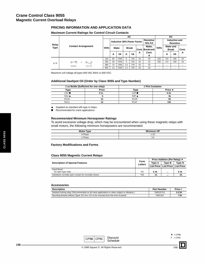
Crane Control Class 9055
Magnetic Current Overload Relays
148
CL
AS
S 9
05
5
PRICING INFORMATION AND APPLICATION DATA
Maximum coil voltage all types 600 VAC 60Hz or 600 VDC.
▲ Supplied as standard with type A relays.● Recommended for crane applications.
Factory Modifications and Forms
Maximum Current Ratings for Control Circuit Contacts
Relay Type
Contact Arrangement
AC DC
Volts
Inductive 35% Power FactorResistive 75% P.F.
Volts
Inductive and Resistive
Make BreakCont.
A
Make, Break and
Cont.A
Make and Break Cont.
AA VA A VA A VA
A, N
120 60 7200 6 720 10 10 125 0.8 100 10
240 30 7200 3 720 10 10 250 0.4 100 10
480 15 7200 1.5 720 10 10 ... ... ... ...
600 12 7200 1.2 720 10 10 ... ... ... ...
Additional Dashpot Oil (Order by Class 9055 and Type Number)
1 oz Bottle (Sufficient for one relay) 1 Pint ContainerType Price Type Price a
C2U ● $ 11. C2P ● $ 44.
R2U ▲ 9. R2P ▲ 36.
R1OU 16. R1OP 96.
R11U 16. R11P 108.
Recommended Minimum Horsepower RatingsTo avoid excessive voltage drop, which may be encountered when using these magnetic relays with small motors, the following minimum horsepowers are recommended.
Motor Type Minimum HP3-Phase 1-1/2
1-Phase 1/2
Class 9055 Magnetic Current Relays
Description of Special FeaturesForm
Letters
Price Addition (Per Relay) aType A Type B Type N
List Price List Price List PriceHand Reset:
On open type relay . . . . . . . . . . . . . . . . . . . . . . . . . . . . . . . . . . . . . . . . . . . . . . . . . . . . . . . . . H3 $ 18. ... $ 18.
Substitute normally-open contact for normally-closed . . . . . . . . . . . . . . . . . . . . . . . . . . . . . . . . Y44 12. ... 18.
AccessoriesDescription Part Number Price hDashpot locking strap. (Recommended on all crane applications or when subject to vibration.) 750D107G1 $ 2.50
Mounting Bracket (Allows Types 101 thru 121 to be mounted from the front of panel) 750X103 7.00
or
(Standard) (Form Y44)
CP9B CP9C DiscountSchedule
a = CP9B
h = CP9C
© 1998 Square D All Rights Reserved 7/98
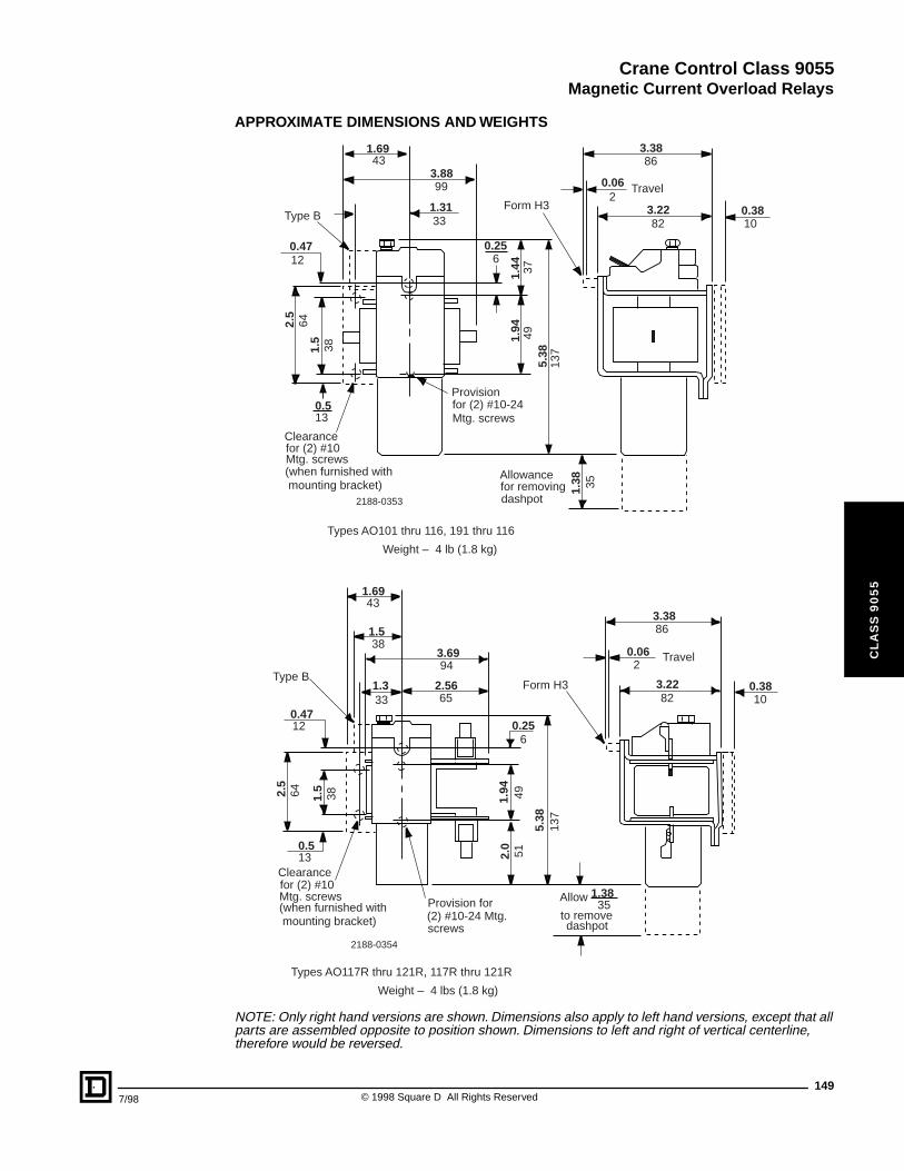
Crane Control Class 9055
Magnetic Current Overload Relays
7/98
CL
AS
S 9
05
5
APPROXIMATE DIMENSIONS AND WEIGHTS
NOTE: Only right hand versions are shown. Dimensions also apply to left hand versions, except that all parts are assembled opposite to position shown. Dimensions to left and right of vertical centerline, therefore would be reversed.
0.3810
3.3886
0.062
Travel
3.2282
Form H3
1.6943
3.8899
1.3133Type B
0.4712
1.44 37
1.94
495.
3813
7
0.256
Provisionfor (2) #10-24Mtg. screws
2.5
641.
538
0.513
Clearancefor (2) #10Mtg. screws(when furnished with mounting bracket)
(when furnished with mounting bracket)
1.38 35
Allowancefor removingdashpot
Types AO101 thru 116, 191 thru 116
Weight – 4 lb (1.8 kg)
2188-0353
3.3886
0.062
Travel
Form H3 3.2282
0.3810
1.3835
Allow
to removedashpot
Types AO117R thru 121R, 117R thru 121R
Provision for(2) #10-24 Mtg.screws
5.38
137
2.0
511.
94 49
0.256
3.6994
2.5665
Clearancefor (2) #10Mtg. screws
0.513
2.5
64 1.5
38
0.4712
Type B1.333
1.538
1.6943
2188-0354
Weight – 4 lbs (1.8 kg)
149© 1998 Square D All Rights Reserved
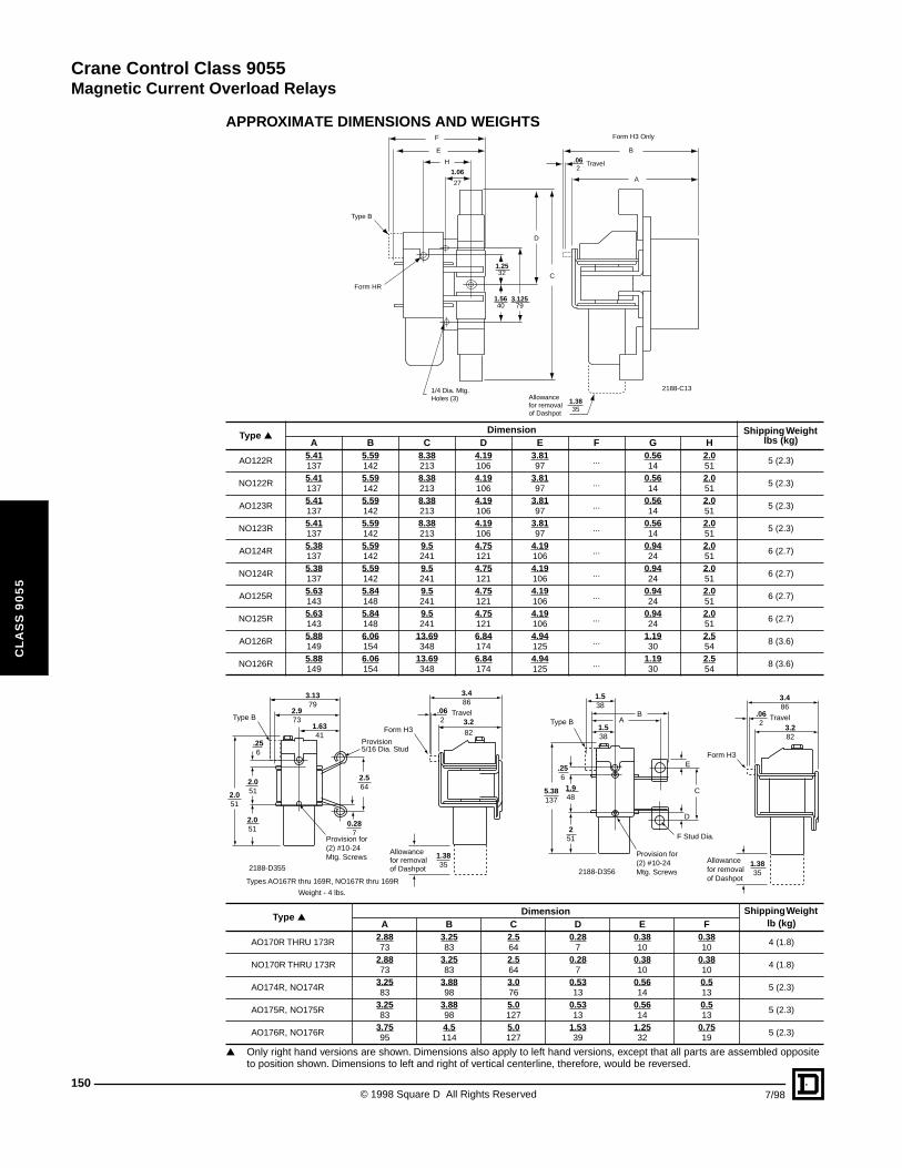
Crane Control Class 9055
Magnetic Current Overload Relays
150
CL
AS
S 9
05
5
APPROXIMATE DIMENSIONS AND WEIGHTS
▲ Only right hand versions are shown. Dimensions also apply to left hand versions, except that all parts are assembled opposite to position shown. Dimensions to left and right of vertical centerline, therefore, would be reversed.
Type ▲Dimension Shipping Weight
lbs (kg)A B C D E F G H
AO122R5.41137
5.59142
8.38213
4.19106
3.8197
...0.5614
2.051
5 (2.3)
NO122R5.41137
5.59142
8.38213
4.19106
3.8197
...0.5614
2.051
5 (2.3)
AO123R5.41137
5.59142
8.38213
4.19106
3.8197
...0.5614
2.051
5 (2.3)
NO123R5.41137
5.59142
8.38213
4.19106
3.8197
...0.5614
2.051
5 (2.3)
AO124R5.38137
5.59142
9.5241
4.75121
4.19106
...0.9424
2.051
6 (2.7)
NO124R5.38137
5.59142
9.5241
4.75121
4.19106
...0.9424
2.051
6 (2.7)
AO125R5.63143
5.84148
9.5241
4.75121
4.19106
...0.9424
2.051
6 (2.7)
NO125R5.63143
5.84148
9.5241
4.75121
4.19106
...0.9424
2.051
6 (2.7)
AO126R5.88149
6.06154
13.69348
6.84174
4.94125
...1.1930
2.554
8 (3.6)
NO126R5.88149
6.06154
13.69348
6.84174
4.94125
...1.1930
2.554
8 (3.6)
Type ▲Dimension Shipping Weight
lb (kg)A B C D E F
AO170R THRU 173R2.8873
3.2583
2.564
0.287
0.3810
0.3810
4 (1.8)
NO170R THRU 173R2.8873
3.2583
2.564
0.287
0.3810
0.3810
4 (1.8)
AO174R, NO174R3.2583
3.8898
3.076
0.5313
0.5614
0.513
5 (2.3)
AO175R, NO175R3.2583
3.8898
5.0127
0.5313
0.5614
0.513
5 (2.3)
AO176R, NO176R3.7595
4.5114
5.0127
1.5339
1.2532
0.7519
5 (2.3)
2188-C13Allowancefor removalof Dashpot
1/4 Dia. Mtg.Holes (3)
Form HR
Type B
F
E
H
1.06
27
D
C
3.12579
A
Form H3 Only
.062
B
1.3835
1.5640
1.2532
Travel
Type B
Provision for(2) #10-24 Mtg. Screws
3.1379
2.973
.062
1.6341
.256
Provision5/16 Dia. Stud
Form H3
3.486
3.282
Travel
2.564
0.287
Allowancefor removal of Dashpot
1.3835
2.051
2.051
2.051
Types AO167R thru 169R, NO167R thru 169R
Weight - 4 lbs.
2188-D355
AB
1.538
1.538
.256
1.948
5.38137
251
Type B
E
D
C
F Stud Dia.
Provision for (2) #10-24Mtg. Screws
1.3835
Allowancefor removalof Dashpot
3.282
.062
3.486
Form H3
Travel
2188-D356
© 1998 Square D All Rights Reserved 7/98
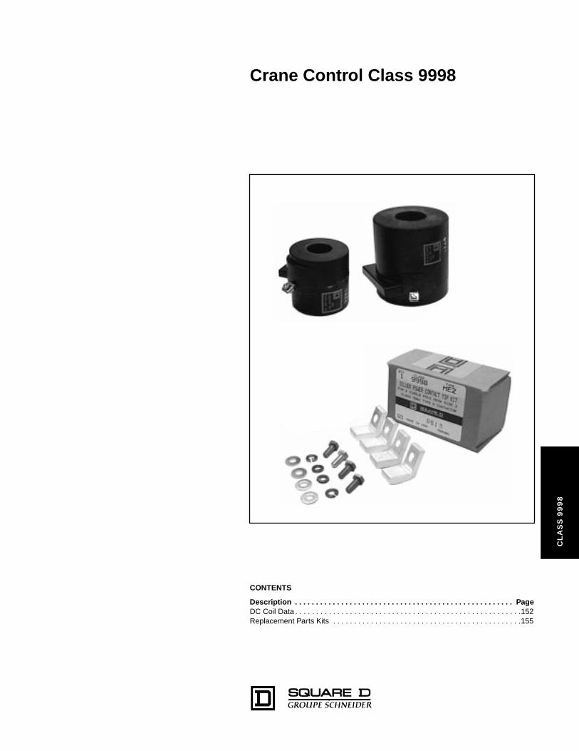
Crane Control Class 9998
CL
AS
S 9
99
8
CONTENTS
Description . . . . . . . . . . . . . . . . . . . . . . . . . . . . . . . . . . . . . . . . . . . . . . . . . . . . PageDC Coil Data . . . . . . . . . . . . . . . . . . . . . . . . . . . . . . . . . . . . . . . . . . . . . . . . . . . . . .152Replacement Parts Kits . . . . . . . . . . . . . . . . . . . . . . . . . . . . . . . . . . . . . . . . . . . . .155
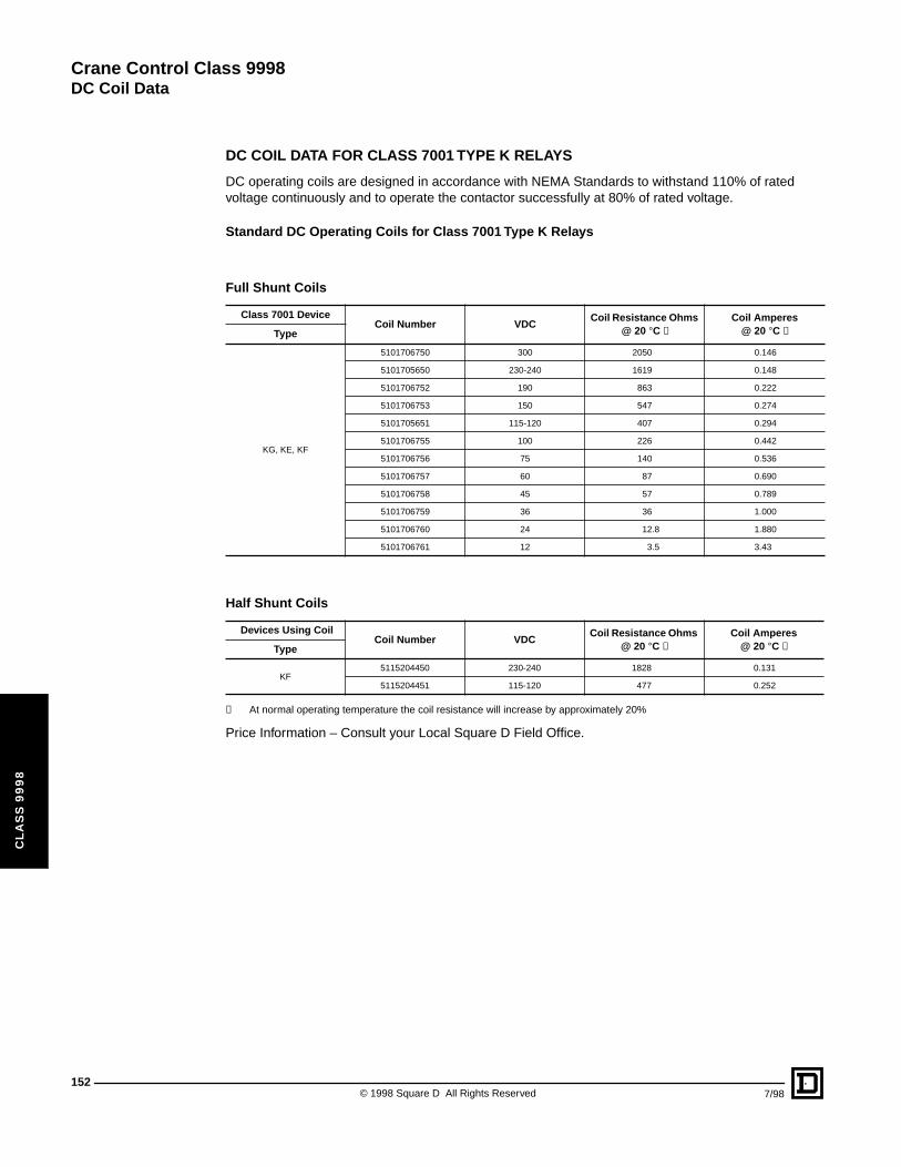
Crane Control Class 9998
DC Coil Data
152
CL
AS
S 9
99
8
DC COIL DATA FOR CLASS 7001 TYPE K RELAYS
DC operating coils are designed in accordance with NEMA Standards to withstand 110% of rated voltage continuously and to operate the contactor successfully at 80% of rated voltage.
Standard DC Operating Coils for Class 7001 Type K Relays
✝ At normal operating temperature the coil resistance will increase by approximately 20%
Price Information – Consult your Local Square D Field Office.
Full Shunt Coils
Class 7001 DeviceCoil Number VDC
Coil Resistance Ohms @ 20 °C ✝
Coil Amperes @ 20 °C ✝Type
KG, KE, KF
5101706750 300 2050 0.146
5101705650 230-240 1619 0.148
5101706752 190 863 0.222
5101706753 150 547 0.274
5101705651 115-120 407 0.294
5101706755 100 226 0.442
5101706756 75 140 0.536
5101706757 60 87 0.690
5101706758 45 57 0.789
5101706759 36 36 1.000
5101706760 24 12.8 1.880
5101706761 12 3.5 3.43
Half Shunt Coils
Devices Using CoilCoil Number VDC
Coil Resistance Ohms @ 20 °C ✝
Coil Amperes @ 20 °C ✝Type
KF5115204450 230-240 1828 0.131
5115204451 115-120 477 0.252
© 1998 Square D All Rights Reserved 7/98
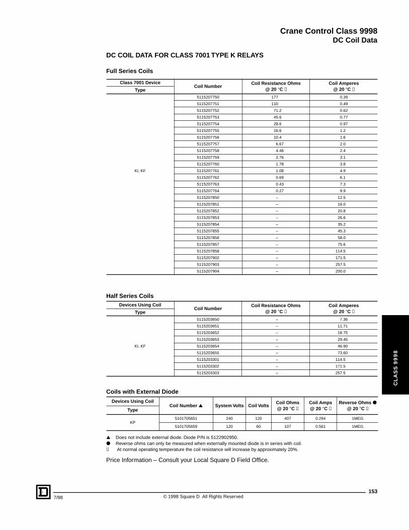
Crane Control Class 9998
DC Coil Data
7/98
CL
AS
S 9
99
8
DC COIL DATA FOR CLASS 7001 TYPE K RELAYS
Full Series Coils
▲ Does not include external diode. Diode P/N is 5122902950.● Reverse ohms can only be measured when externally mounted diode is in series with coil.✝ At normal operating temperature the coil resistance will increase by approximately 20%.
Price Information – Consult your Local Square D Field Office.
Class 7001 DeviceCoil Number
Coil Resistance Ohms @ 20 °C ✝
Coil Amperes @ 20 °C ✝Type
KI, KF
5115207750 177 0.39
5115207751 110 0.49
5115207752 71.2 0.62
5115207753 45.6 0.77
5115207754 28.6 0.97
5115207755 16.6 1.2
5115207756 10.4 1.6
5115207757 6.67 2.0
5115207758 4.46 2.4
5115207759 2.76 3.1
5115207760 1.78 3.8
5115207761 1.08 4.9
5115207762 0.69 6.1
5115207763 0.43 7.3
5115207764 0.27 9.9
5115207850 – 12.5
5115207851 – 16.0
5115207852 – 20.8
5115207853 – 26.6
5115207854 – 35.2
5115207855 – 45.3
5115207856 – 58.0
5115207857 – 75.6
5115207858 – 114.5
5115207902 – 171.5
5115207903 – 257.5
5115207904 – 200.0
Half Series CoilsDevices Using Coil
Coil NumberCoil Resistance Ohms
@ 20 °C ✝Coil Amperes
@ 20 °C ✝Type
KI, KF
5115203650 – 7.36
5115203651 – 11.71
5115203652 – 18.75
5115203653 – 29.45
5115203654 – 46.90
5115203655 – 73.60
5115203301 – 114.5
5115203302 – 171.5
5115203303 – 257.5
Coils with External Diode
Devices Using CoilCoil Number ▲ System Volts Coil Volts
Coil Ohms@ 20 °C ✝
Coil Amps @ 20 °C ✝
Reverse Ohms ●
@ 20 °C ✝Type
KP5101705651 240 120 407 0.294 1MEG
5101705659 120 60 107 0.561 1MEG
153© 1998 Square D All Rights Reserved
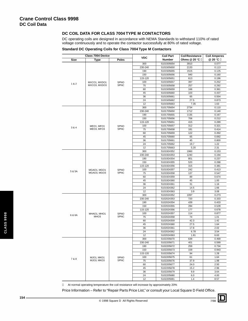
Crane Control Class 9998
DC Coil Data
154
CL
AS
S 9
99
8
DC COIL DATA FOR CLASS 7004 TYPE M CONTACTORSDC operating coils are designed in accordance with NEMA Standards to withstand 110% of rated voltage continuously and to operate the contactor successfully at 80% of rated voltage.
✝ At normal operating temperature the coil resistance will increase by approximately 20%
Price Information – Refer to “Repair Parts Price List,” or consult your Local Square D Field Office.
Standard DC Operating Coils for Class 7004 Type M Contactors
Class 7004 DeviceVDC
Coil Part Number
Coil Resistance Ohms @ 20 °C ✝
Coil Amperes @ 20 °C ✝Size Type Poles
1 & 2MXCO1, MXDO1MXCO3, MXDO3
SPNOSPNC
300 5101505654 3910 0.077
230-240 5101505650 2133 0.113
190 5101505655 1515 0.125
150 5101505656 940 0.160
115-120 5101505651 613 0.196
100 5101505657 397 0.252
75 5101505658 257 0.292
60 5101505659 166 0.361
45 5101505660 103 0.437
36 5101505661 65 0.554
24 5101505662 27.5 0.873
12 5101505663 7.35 1.63
3 & 4MEO1, MFO1 MEO3, MFO3
SPNOSPNC
300 5101705654 2734 0.110
230-240 5101705650 1712 0.140
190 5101705655 1135 0.167
150 5101705656 706 0.212
115-120 5101705651 415 0.289
100 5101705657 312 0.321
75 5101705658 181 0.414
60 5101705659 122 0.492
45 5101705660 65 0.692
36 5101705661 45 0.800
24 5101705662 19.7 1.22
12 5101705663 5.20 2.31
5 & 5AMGAO1, MGO1 MGAO3, MGO3
SPNOSPNC
300 5101924352 1960 0.153
230-240 5101924353 1240 0.194
190 5101924354 801 0.237
150 5101924355 520 0.288
115-120 5101924356 315 0.381
100 5101924357 242 0.413
75 5101924358 137 0.547
60 5101924359 89 0.674
45 5101924360 45 1.00
36 5101924361 31 1.16
24 5101924362 14.5 1.66
12 5101924363 3.9 3.08
6 & 6AMHAO1, MHO1
MHO3SPNOSPNC
300 5102024352 1097 0.273
230-240 5102024353 720 0.333
190 5102024354 439 0.433
150 5102024355 284 0.528
115-120 5102024356 177 0.678
100 5102024357 114 0.877
75 5102024358 74 1.01
60 5102024359 42.3 1.42
45 5102024360 27.5 1.64
36 5102024361 17.8 2.02
24 5102024362 6.78 3.54
12 5102024363 1.81 6.63
7 & 8MJO1, MKO1 MJO3, MKO3
SPNOSPNC
300 5102205670 639 0.469
230-240 5102205671 401 0.599
190 5102205672 259 0.734
150 5102205673 159 0.943
115-120 5102205674 94 1.28
100 5102205675 61 1.64
75 5102205676 37.9 1.98
60 5102205677 24.0 2.50
45 5102205678 15.2 2.96
36 5102205679 9.9 3.64
24 5102205680 6.0 4.00
12 5102205681 1.4 8.57
© 1998 Square D All Rights Reserved 7/98
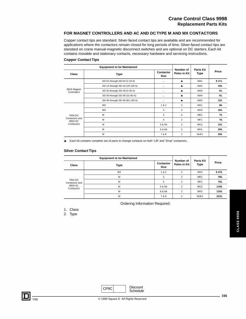
Crane Control Class 9998
Replacement Parts Kits
7/98
CL
AS
S 9
99
8
FOR MAGNET CONTROLLERS AND AC AND DC TYPE M AND MX CONTACTORS
Copper contact tips are standard. Silver-faced contact tips are available and are recommended for applications where the contactors remain closed for long periods of time. Silver-faced contact tips are standard on crane manual-magnetic disconnect switches and are optional on DC starters. Each kit contains movable and stationary contacts, necessary hardware and servicing instructions.
▲ Each kit contains complete set of parts to change contacts on both “Lift” and “Drop” contactors.
Ordering Information Required:
1. Class2. Type
Copper Contact Tips
Equipment to be MaintainedNumber of Poles in Kit
Parts Kit Type
PriceClass Type
Contactor Size
6815 Magnet Controllers
AD-01 through AD-04 (2-19 A) ... ▲ MA1 $ 171.
AD-13 through AD-16 (19-130 A) ... ▲ MA2 165.
SD-20 through SD-29 (2-30 A) ... ▲ MA3 81.
SD-30 through SD-39 (31-80 A) ... ▲ MA4 81.
SD-40 through SD-49 (81-130 A) ... ▲ MA5 122.
7004 DC Contactors and
8503 AC Contactors
MX 1 & 2 2 MX1 86.
MX 3 2 MX3 182.
M 3 2 ME1 70.
M 4 2 MF1 78.
M 5 & 5A 2 MG1 102.
M 6 & 6A 2 MH1 206.
M 7 & 8 2 MJK1 356.
Silver Contact Tips
Equipment to be MaintainedNumber of Poles in Kit
Parts Kit Type
PriceClass Type
Contactor Size
7004 DC Contactors and
8503 AC Contactors
MX 1 & 2 2 MX2 $ 476.
M 3 2 ME2 766.
M 4 2 MF2 792.
M 5 & 5A 2 MG2 1108.
M 6 & 6A 2 MH2 1330.
M 7 & 8 2 MJK2 2216.
CP9C DiscountSchedule
155© 1998 Square D All Rights Reserved
Crane Control Class 9998
156
CL
AS
S 9
99
8
© 1998 Square D All Rights Reserved 7/98
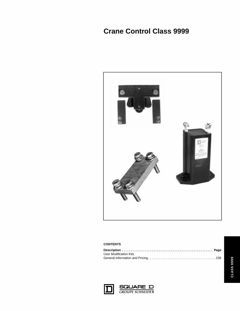
Crane Control Class 9999
99
9
CONTENTS
Description . . . . . . . . . . . . . . . . . . . . . . . . . . . . . . . . . . . . . . . . . . . . . . . . . . . . PageUser Modification KitsGeneral Information and Pricing . . . . . . . . . . . . . . . . . . . . . . . . . . . . . . . . . . . . . . .158
CL
AS
S 9
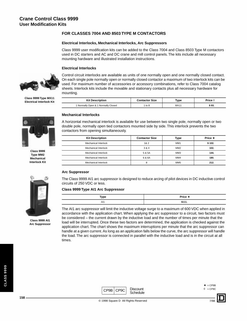
Crane Control Class 9999
User Modification Kits
158
CL
AS
S 9
99
9
Class 9999 AI1Arc Suppressor
Class 9999 Type MX11Electrical Interlock Kit
Class 9999Type MM2
MechanicalInterlock Kit
FOR CLASSES 7004 AND 8503 TYPE M CONTACTORS
Electrical Interlocks, Mechanical Interlocks, Arc Suppressors
Class 9999 user modification kits can be added to the Class 7004 and Class 8503 Type M contactors used in DC starters and AC and DC crane and mill control panels. The kits include all necessary mounting hardware and illustrated installation instructions.
Electrical Interlocks
Control circuit interlocks are available as units of one normally open and one normally closed contact. On each single pole normally open or normally closed contactor a maximum of two interlock kits can be used. For maximum number of accessories or accessory combinations, refer to Class 7004 catalog sheets. Interlock kits include the movable and stationary contacts plus all necessary hardware for mounting.
Mechanical Interlocks
A horizontal mechanical interlock is available for use between two single pole, normally open or two double pole, normally open tied contactors mounted side by side. This interlock prevents the two contactors from opening simultaneously.
Arc Suppressor
The Class 9999 AI1 arc suppressor is designed to reduce arcing of pilot devices in DC inductive control circuits of 250 VDC or less.
The AI1 arc suppressor will limit the inductive voltage surge to a maximum of 600 VDC when applied in accordance with the application chart. When applying the arc suppressor to a circuit, two factors must be considered – the current drawn by the inductive load and the number of times per minute that the load will be interrupted. Once these two factors are determined, the application is checked against the application chart. The chart shows the maximum interruptions per minute that the arc suppressor can handle at a given current. As long as an application falls below the curve, the arc suppressor will handle the load. The arc suppressor is connected in parallel with the inductive load and is in the circuit at all times.
Kit Description Contactor Size Type Price h
1 Normally Open & 1 Normally Closed 1 to 8 MX11 $ 93.
Kit Description Contactor Size Type Price a
Mechanical Interlock 1& 2 MM1 $ 102.
Mechanical Interlock 3 & 4 MM2 102.
Mechanical Interlock 5 & 5A MM3 144.
Mechanical Interlock 6 & 6A MM4 180.
Mechanical Interlock 8 MM5 212.
Class 9999 Type AI1 Arc Suppressor
Type Price a
AI1 $111.
CP9B CP9C DiscountSchedule
a = CP9B
h = CP9C
© 1998 Square D All Rights Reserved 7/98

Crane Control Class 9999
User Modification Kits
7/98
CL
AS
S 9
99
9
Application Chart for AI1 Arc Suppressor
APPROXIMATE DIMENSIONS AND WEIGHTS
Ordering Information Required:
1. Class2. Type
10
CURRENT IN AMPERES
PE
RM
ISS
IBL
E IN
TE
RR
UP
TIO
NS
PE
R M
INU
TE
0.4 0.5 0.6 0.7 0.8 0.9 1.0 1.1 1.2 1.3 1.4
20
30
40
50
60
L = 11H
L = 20H
57
111
25
49
42 76
6.3
95
2.25
4.38
1.00
1.93
1.65 3.00
0.25
3.75
Clearance for (2)1/4" mtg. screws
mmDual Dimensions: inches
Net Weight – 1 lb (0.45 kg)
159© 1998 Square D All Rights Reserved

Crane Control Class 9999
User Modification Kits
160
CL
AS
S 9
99
9
Class 9999 Type MT2Tie Bar Kit
Class 9999 Type ML1Lug Kit
Class 9999 Type KX3 Contact Kit
Class 9999 Type KX5 Contact Kit
FOR CLASS 7001 TYPE K RELAYS AND CLASSES 7004 AND 8503 TYPE M CONTACTORS
Tie Bar - Power Lugs - Control Circuit Contacts
Tie Bar
Applications requiring double pole normally open Type M contactors can be met by supplying single pole normally open contactors with tie bars. The tie bar is made from an insulating material and connects the armatures of the contactors together. For double pole contactors, it is recommended that the operating coils be connected in series. Each coil should be rated for one half of line voltage.
For Use With Class 7004 DC & 8503 AC Contactors
Power Lugs for Type M Contactors
Type M contactors are furnished without power lugs. A kit is available consisting of lugs and hardware for mounting on Size 3 and larger contactors. No power lug kits are available for the NEMA Size 1 and 2 contactors. These contactors are designed to use lugs supplied by the user.
▲ Contains four clam shell type lugs. For copper conductors only.
Control Circuit Contacts for Class 7001 Type K Relays
Ordering Information Required:
1. Class2. Type
Kit Description Contactor Size Type Price
Tie Bar Kit 1& 2 MT1 $ 36.
Tie Bar Kit 3 & 4 MT2 36.
Tie Bar Kit 5 & 5A MT3 36.
Tie Bar Kit 6 & 6A MT4 60.
Tie Bar Kit 7 & 8 MT5 60.
Kit DescriptionContactor Size Type ▲ Price
Min. Wire Size Max. Wire Size
#8 #00 4 ML1 $ 36.
#0 300 MCM 5 & 5A ML2 60.
250 MCM 500 MCM 6, 6A, 7 & 8 ML3 138.
Description For Use on Relay Type Type Price
1 N.O. and 1 N.C. Contact KG, KE, KI, KP KX3 $ 77.
1 N.O. Contact KF KX4 201.
1 N.C. Contact KF KX5 201.
CP9B DiscountSchedule
© 1998 Square D All Rights Reserved 7/98
Crane Control Class 9999
7/98
161© 1998 Square D All Rights Reserved

162
© 1998 Square D All Rights Reserved 7/98

163
7/98 © 1998 Square D All Rights Reserved

Catalog No. 6100CT9702 July 1998 © 1998 Square D All Rights Reserved.
FRONTLINE, YOUNGSTOWN, TAB-WELD, LINE-ARC, EDDYMAG, Square D and are registered trademarks of Square D Company.
Square D CompanyP.O. Box 9247Columbia, SC 29290, USA(803) 776-7500
CRANE-PAK and CONTRA-TORQUE are trademarks of Square D Company