Clase de Balcarse Ingenieria Geologica
24
Characteristics of Reservoir Rocks
-
Upload
brunozalazar -
Category
Documents
-
view
14 -
download
6
description
well
Transcript of Clase de Balcarse Ingenieria Geologica

Characteristics of Reservoir Rocks
Isothermal expansion from the liquid phaseleads to the formation of gas at the bubhlc-point.and a monotonic irlcrcase ill \rolume of the gas phaseas pressure declines further
To form a commercial reservoir of hydrocarbons,any geological formation must exhibit two essentialcharacteristics. These are a capacity for storage andtransn~issibility to the fluid concerned,

thereservoir rock must be able to accumulate and storcfluids, and when devclopment wells are drilled itmust be possible for those reservoir fluids to flowthrough relatively long distances under small potentialgradients.

Storage capacity requires void spaces within therock, and transmissibility requires that therc shouldbe continuity of those void spaces
The first characteristicis termed porosity, the second permeability.

While some estimates of reservoir rock propertiescan be made from electrical and radioactive logsurvcys, the study of core samples of the rcservoirrock are always essential.

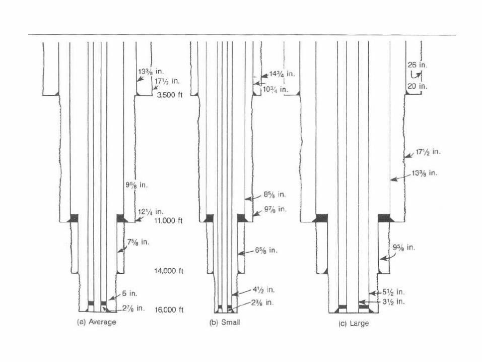
A core is a sample of rock from the well section,generally obtained by drilling into the formationwith a hollow section drill pipe and drill bit
There isa facility to retain the drilled rock as a cylindricalsamplc with the dimensions of the internal crosssectionalarea of the cutting bit and the lcngth of thehollow section.
With conventionul equipment, thisresults in cores up to 10 m in lcngth and 11 cm indiameter.
The recovered core represents the record of rocktype in the well scction and is the basic data forinterpretation of geological and cnginecring properties.
In general, two partially conflicting objectivesmust be met when taking core samples. In the firstplace, a careful on-site examination for hydrocarbontraces is desirable (e.g. gas bubbling or oil seepingfrom the core, core fluorescence on a freshlyexposed surface, fluorescence and staining in solventcuts ctc.), in case an opcn hole drill stem test ispossible and desirable.
In the sccond place, it isdesirable to preserve the core in as unchangcd acondition as possiblc prior to laboratory evaluation
The equilibrium saturation distribution in a petroleurn-reservoir prior to production is governed bythe pore space characteristics
This happens as aresult of non-wetting phase fluid (hydrocarbons)entering pore space iilitially occupied by wettingphase fluid (water) during migration of hydrocarbonsfrom a source rock region into a reservoir trap
A pressure differential is required for non-wettingphase fluid to displace wetting phase fluid and this isequivalent to a minimum threshold capillary pressureand is dcnendent on vore size
Capillary pressure may be defined as the pressuredifference across a curved interface between twoimmiscible fluids. Using the example of an oil dropin a water environment
The capillary pressure PC is defined asthe difference between the two phase pressures
The pore size distribution in a givcn rock type, whichhas been shown to influence saturation distribution,is usually deterrnined using a mercury injection test.
Although this test is destructive, in the sense that thesample cannot be used again, it has the advantagethat high pressures can bc attained and mercury, thenon-wetting phase with respect to air, can be forcedinto very small pores.

IN-PLACE VOLUME
The volume of hydrocarbon in place in a reservoirdepends on:(a) the areal extent of the hydrocarbon region ofthe reservoir;(b) the thickness of reservoir quality porous rockin the hydrocarbon rcgion;(c) the porosity of reservoir quality porous rockin the hydrocarbon rcgion;(d) the saturation ot hydrocarbon in the hydrocarbonregion.This is represented in terms of avcrage properties asfollows

At standard conditions, the volurne of hydrocarbonin place is the reservoir condition volumedivided by the formation volume factor. Each of thecomponents of the volumetric equation is subject touncertainty and spatial variation. We shall nowexamine the source and representation of these dataand develop a probabilistic approach to volumctricestimation.

The areal extent of reservoirs are defined with somedegree of uncertainty by evidence from drilled wellscombined with geophysical interpretation of seismicdata.
Maps tend to represent timestratigraphy as depositional units. Since reservoirfluids are contained in, and recovered from, permeablebeds, the combination of permeable elcmentsof a number of time stratigraphic units leads tomappable rock stratigraphic units having (a) arealextent, (b) thickness, (c) petrophysical properties.

Structure contour maps are used to connect pointsof equal elevation. It is customary to map structureat the top and base of porosity and the map indicatesthe external geometry of the reservoir.
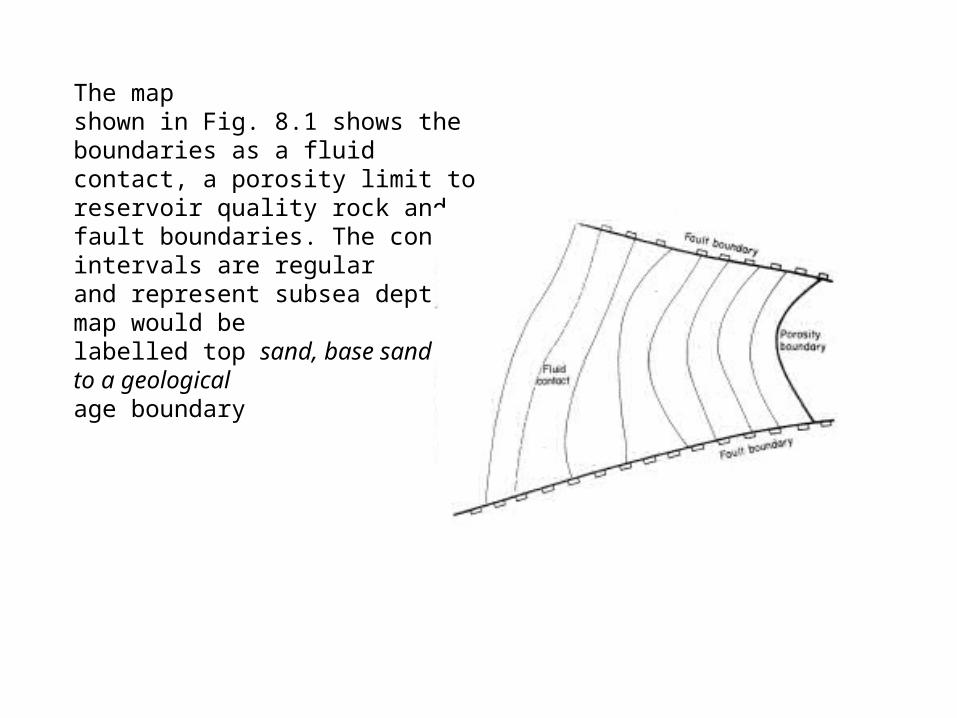
The mapshown in Fig. 8.1 shows the boundaries as a fluidcontact, a porosity limit to reservoir quality rock andfault boundaries. The contour intervals are regularand represent subsea depths. The map would belabelled top sand, base sand or refer to a geologicalage boundary
The difference in elevation betweenthe hydrocarbon-water contact and the top of thestructure is known as the closure or height of the Contour interval hydrocarbon column.

LITHOFACIES REPRESENTATION

Rock lithology can provide a guide in contouring,and lithofacies maps are generally presented as ratiomaps, typically sand: shale or limestone: anhydrite

WELL TEST PROCEDURES
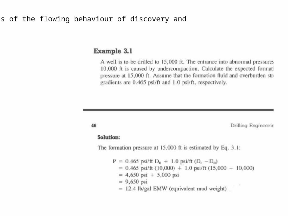
Tests of the flowing behaviour of discovery and