
Clarus Manual
26
Clarus-Series Component Systems Installation Manual & Car Audio Reference Guide
-
Upload
alberts-rockingham -
Category
Documents
-
view
72 -
download
0
Transcript of Clarus Manual

5/14/2018 Clarus Manual - slidepdf.com
http://slidepdf.com/reader/full/clarus-manual 1/26
Clarus-Series Component SystemsInstallation Manual & Car Audio Reference Guid

5/14/2018 Clarus Manual - slidepdf.com
http://slidepdf.com/reader/full/clarus-manual 2/26
Contents
Welcome and Introduction .................................................................................................................................................
Clarus Individual Component Parameters.......................................................................................................................
Midbass Speakers (Clarus C5 and Clarus C6)..........................................................................................................
Tweeter Speakers (Clarus C1)......................................................................................................................................
Clarus System Specifications ............................................................................................................................................
Thiele/Small Parameter Discussion for Clarus Midbass Speakers ........................................................................
Midbass Thiele/Small Parameters ................................................................................................................................
Clarus C51-2 Mechanical Drawing ...................................................................................................................................
Clarus C61-2 Mechanical Drawing ...................................................................................................................................
Clarus C2x Passive Crossover Mechanical Drawing ...................................................................................................
Clarus C1 Tweeter Mechanical Drawing (Installed in Flush-Mount Cup) ..................................................................
Clarus C1 Tweeter Mechanical Drawing (Installed in Angle-Mount Cup) .................................................................
C51-2 Frequency Response Graph ................................................................................................................................
C61-2 Frequency Response Graph ................................................................................................................................
Unpacking/Inventory ..........................................................................................................................................................
How to Use This Manual ...................................................................................................................................................
Section I - Getting Started – Basic System Installation ................................................................................................
Section II - Moving Forward – Advanced System Installation .....................................................................................
Lessons Learned ............................................................................................................................................................
Lesson One: Off-Axis Response..................................................................................................................................
Lesson Two: Equalization of Pathlength Differences ...............................................................................................
Lesson Three: The Effect of HRTF, ITD, and IID ......................................................................................................
Lesson Four: Point-Sourcing ........................................................................................................................................
Lesson Five: Reference ................................................................................................................................................
Advanced Installation of the Clarus Component Systems...........................................................................................
Mounting Baffle Considerations ...................................................................................................................................
Acoustic Treatment ........................................................................................................................................................
Advanced Installation Conclusions ..................................................................................................................................
Warranty ..............................................................................................................................................................................
Thank You! ..........................................................................................................................................................................

5/14/2018 Clarus Manual - slidepdf.com
http://slidepdf.com/reader/full/clarus-manual 3/26
Clarus User’s Manual ©Hybrid Audio Technologies Page 3 o
Welcome and Introduction
Congratulations on your purchase of high performance Clarus-series mobile audio componloudspeakers, and welcome to the world of Hybrid Audio Technologies, where high-end mobile auloudspeaker development is our passion! When installed and set-up properly, the Clarus componsystem you have purchased will make a remarkable improvement in the sound quality of virtually amobile audio sound system and give years of superior performance.
Thank you for going “on line” to read and download your User’s Manual. Our offices are locaamongst the evergreens in North Georgia USA, and we happen to like trees. Aside from the obvioaesthetic benefits, trees improve our air, protect our water, save energy, and improve economsustainability. Additionally, it is expensive to print and distribute thousands of copies of an ownemanual; we’d rather invest our production dollars into an incredible line-up of speaker systems your listening pleasure. With online resources becoming the main source of information for more amore people, we are pleased that you’re here, reading this manual on line, verses having a print cowhich might get read once and put back into the gift box, or worse yet, discarded.
With the publication of this user’s manual and reference guide, it is our goal to assist the “doyourself” enthusiast and professional installer alike in getting the highest level of performance out
Clarus 2-way component sets using straight-forward installation advice and practical applicationtimeless acoustic principles. As you begin to read this document, you will quickly realize that thisnot your typical user’s manual. This manual has been written to be more or less a miniature mobaudio reference guide that can be used to better any sound system, and in particular, a system tutilizes the Clarus component speaker systems. It is an introductory primer to the world of high-emobile audio; we hope this user’s manual is not only informative, but motivating. Keep it hanthroughout your installation process, and any time you go to improve your audio system with otHybrid Audio Technologies products, or perhaps to take advantage of our lifetime guaranteed vatrade-in program. We are confident that if the principles explained in this manual are exercised in yoown installation, you will be ecstatic with the sound quality outcome!
We realize that you have a choice in loudspeakers, and are thrilled that you have chosen the Clarseries. For more information about Hybrid Audio Technologies, our philosophies regarding high-emobile audio, to learn more about our lifetime guaranteed value program, and for information abour other products, please visit us online at www.hybrid-audio.com.
Thank you, and happy listening!
Scott E. BuwaldaFounder – Hybrid Audio Technologies

5/14/2018 Clarus Manual - slidepdf.com
http://slidepdf.com/reader/full/clarus-manual 4/26
Clarus User’s Manual ©Hybrid Audio Technologies Page 4 o
Clarus Individual Component Parameters
Your Clarus system contains speaker drivers and passive crossover networks that were developand assembled with a significant effort in research and development, materials science engineerian exhaustive level of sampling and prototyping, real-world testing, and obsessive attention to detThe specifications and parameters of your Clarus component system is detailed as follows:
Midbass Speakers (Clarus C5 and Clarus C6)
Frame: Cast aluminum with black powder-texture surface coating. The basket is a high-quality caluminum design, which plays a critical role in aligning the voice coil in the magnetic circAdditionally, the cast aluminum frame allows for better clamping strength verses typical stamped stframes, and ensures that the voice coil remains centered in the former. The black coating on frame protects it from abrasion and oxidation. The frames are similar in size and format to the MirImagine, and Clarus-series drivers, allowing for upgrade potential from these product lines to Clarus series.
Cone and Dustcap: Pressed paper, untreated on the front side and treated on the rearward sideis widely acknowledged that pressed paper cones are the best marriage of lightness, stiffness, aability of the cone to damp unwanted cone and edge modes and resonances (read: distortion). Tdamping afforded by the paper cone ensures the midbass speakers can play lower treble frequenceffortlessly, without significant cone “breakup.” Our approach to “point-source imaging” is to rely the midbass driver to effectively reproduce the lower treble frequencies, where the human vorange extends, as well as other imaging-critical musical instruments, ensuring phase-coherimaging and stable, lifelike staging character.
The paper cone, known for its excellent sonic attributes, is water resistant, thanks to a polymdeveloped exclusive and proprietarily by Hybrid Audio Technologies. The treatment does not chanthe look and parameters of the driver like old-fashioned “glossy” polymers which added appreciable amount of moving mass and significantly colored the sound. No, the Clarus cones lolike any “normal” paper cone. The treatment protects the cone from periodic drips (such as insiddoor panel), as well as accidental splashes to the front of the cone.
The dustcap covers the voice coil to keep dirt and debris from fouling the voice coil gap. Since hfrequency information emanates from the center of the cone, a paper dustcap was utilized in concwith the pressed paper cone diaphragm to ensure that the speaker’s response remained linear ithe lower- to mid-treble frequencies.
Surround: Inverted high-loss rubber surround. The inverted high-loss rubber surround (in concwith the spider, detailed below), helps to provide the compliance and “restorative force” needed the Clarus drivers to play effectively into the lower midbass, and even upper subbass frequenc
(depending on in-car cabin gain and other factors). You'll also know a Hybrid Audio midrange amidbass design by its inverted surround; this design feature allows for the use of a smaller heigrille, better clearance with OEM panels, and more flexibility in mounting options. The surround isshared technology with the Imagine series coaxial and convertible component sets.
Spider: Phenolic fabric and tinned tinsel leads. The spider is the brownish/yellow corruga(rippled) fabric that attaches the cone and voice coil. The spider for the Clarus designs was subject of a considerable amount of our research and development. The spider is a phenosymmetrically-rolled fabric which provides excellent restorative force during excursion, and the wov

5/14/2018 Clarus Manual - slidepdf.com
http://slidepdf.com/reader/full/clarus-manual 5/26
Clarus User’s Manual ©Hybrid Audio Technologies Page 5 o
tinsel leads, often not found in speakers in this price range, are an asset to the Clarus line becauthe leads are protected from physical damage and accidental short circuit. The tinsel leads connected to real epoxy PCB, not flimsy cardboard.
Voice Coil and Motor System: 1” (25mm) (C5) and 1.4” (35mm) (C6): complimentary design. Tvoice coil used in the Clarus midbass is a 2-layer aluminized copper wire coils on a round former. “overhung” voice coil was selected to improve sensitivity while still keeping distortion to a minimuThe motor system utilizes a ferrite magnet with rubber protective boot (which can be removed
improve mounting depth), complimented by design with a back plate and rear venting chamberimprove the speaker's thermal power handling and improved ability of the midbass to play at hamplitudes.
Tweeter Speakers (Clarus C1)
Dome: Small diameter impregnated silk textile dome with high-loss rubber suspension. The C1 ishared technology with the high-end Unity U1 tweeter, boasting has an impregnated fine cloth dome diaphragm for a linear, smooth sound, with a high-loss rubber suspension to damp edge modand resonances. The dome is of extremely low mass and is much less susceptible to mechanideformation than other designs, and yet yields a smooth response over the extent of its range.
Hybrid Audio Technologies, we feel larger diaphragm tweeters sound heavy and unremarkable, ladetail in the upper treble frequencies, have undesirable polar response, and are difficult to instAdditionally, we find metal dome tweeters to be harsh, brittle, and sound unrealistic. As a smdiameter, soft-dome tweeter, the C1 is the antithesis of large diaphragm and metal-dome tweetefor the effective and convincing reproduction of treble frequencies.
Voice Coil and Motor System: 20mm complimentary design. The motor assembly is “conventiodynamic”, with a compact neodymium magnet structure to ensure a small footprint size and shalldepth. A perforated grille protects the dome. The voice coil is ferrofluid cooled and damped, and ttweeter housing consists of extruded plastic with three different mounting options in component mode, giving the end-user flexibility in not only placement of the C1 but also in physical installation.
Passive Crossover Network (Clarus C2x)
Alignment: Second order L/R (12 dB/octave) filters for low pass (C5 or C6) and high pass (C1). TC51-2 2-way passive crossover network includes a Clarus low pass and high pass crossovfrequency of 5,700 Hz at 12 dB/octave. The C61-2 2-way passive crossover network includesClarus low pass and high pass crossover frequency of 5,200 Hz at 12 dB/octave. The use of dB/octave filters on both low pass and high pass, often not found in speakers in this price ranminimizes phase-related distortion typical of crossovers with mismatched orders, and ensures phacoherent imaging and staging. The alignment topology is a shared technology to the high-end UU2x crossover design and features asymmetrically-aligned network components.
Network Components: Audiophile grade. The C51-2 and C61-2 passive crossover netwoincorporate super high quality and low tolerance metalized polypropylene film capacitors for bhighpass and low pass, in concert with air-core inductors, and low tolerance non-inductive resistoNo output level switches were used in the passive crossover design because switches add a resisteffect and are typically of extremely low quality. Additionally, “jumper pins” add an unnecessary pof splices in the signal path to the tweeter, and were not included in our design either. Rather,tweeter level adjustments are done on the board level with dedicated non-inductive resistors; tweeattenuation is accomplished by selecting the appropriate output (-3 dB, 0 dB, or +3 dB) on the pass

5/14/2018 Clarus Manual - slidepdf.com
http://slidepdf.com/reader/full/clarus-manual 6/26
Clarus User’s Manual ©Hybrid Audio Technologies Page 6 o
crossover circuit board. The components selected are complimentary and ensure no notable sigdegradation between the input and output side of the crossovers, and serve only to filter frequenresponse, and not to equalize the input signal. The network componentry, design, circuitry, apolyethylene case with transparent cover are shared technologies to the Unity series, and the UnU2x crossover design.
Clarus System Specifications
Parameter Clarus C51-2 Clarus C61-2Frequency Response† 55Hz-22KHz
+/-3dB 50Hz-22KHz+/-3dB
Efficiency 2.83 V/ 1 meter 92.0 dB 93.6 dBContinuous Power Handling (transient music input) 110 watts 120 wattsPeak Power Handling (musical transient peak power handling) 230 watts 250 wattsRecommended Power Range 25-150 watts 25-175 wattsNominal Impedance 4Ω 4Ω
† Typically, in-car response including vehicular “cabin gain”, or the gain expected with midbainstalled in the vehicle, will result in an extended midbass and upper subbass response. This is
result of these frequencies being below the lowest resonance in the vehicle (typically around 50-1Hz in most vehicles, described in more detail on page 23). In more practical terms, install the Clamidbass into your vehicle and you will see a dramatic improvement in midbass and upper subbaoutput, much more so than just simply listening to the Clarus in a large room, or worse yet, “free a(we don’t recommend even trying the Clarus speakers in “free air” without some form of enclosureinfinite baffle for the midbass).
Thiele/Small Parameter Discussion for Clarus Midbass Speakers
The mechanical and electrical parameters of the Clarus midbass speakers are amenable to a variof different installations and speaker locations. The high Qms (Q factor of mechanical system) a
Qts (Q factor of total system), coupled with the driver’s Fs (resonance frequency) allow it to be usin an “infinite baffle” configuration. In more practical terms, install the Clarus midbass such that front and back waves don’t “meet” (as detailed in Section I – Getting Started - Basic SystInstallation), including in a door or kick panel, or in the case of a motorcycle, in the fairing (using othe airspace behind the speaker as a pseudo enclosure), with no need for a real enclosure or “boThe design goes hand in hand with fool-proof, high-end sound quality with minimal work. For madvanced users, please reference the Thiele/Small Parameters for the Clarus-series midbass drive

5/14/2018 Clarus Manual - slidepdf.com
http://slidepdf.com/reader/full/clarus-manual 7/26
Clarus User’s Manual ©Hybrid Audio Technologies Page 7 o
Midbass Thiele/Small Parameters**please note, the following parameters are for the midbass drivers only**
Parameter Clarus C51-2 Clarus C61-2Overall Diameter Φ151.3 mm Φ166 mmMounting Depth 58.3 mm * 78.5 mm *Bolt Circle Diameter Φ138 mm Φ156.5mmMounting Hole Φ 118 mm Φ143.5 mmRecommended Minimum HighpassCrossover Frequency (fourth order)
60 Hz 45 Hz
Pnom Rated Power Input (No Crossover) 40 watts 60 wattsPmax Rated Power Input (No Crossover) 80 watts 120 wattsFrequency Range of midbass driver alone (not includingtweeter device)
60-12,000 Hz+/- 3dB
50-9,000 Hz+/- 3 dB
Mms 7.1 g 14.1 gCms 667 µM/N 674 µM/NBL 3.896 T*m 5.4 T*mVoice Coil Diameter 25.5 mm 35.5 mm
DC Resistance 3.4 Ω 3.4 Ω Fs 73 Hz 50 HzQms 6.358 5.527Qes 0.728 0.532Qts 0.654 0.485Xmax 10mm (two-way) 14mm (two waVas 6.1 L 14.9 LSd 8.012 mm2 12.4692
* Mounting depth includes removable rubber magnet boot cover. By removing the boot cover (wh
does not affect the performance of the midbass), the depth improves by approximately 2.5 mm.
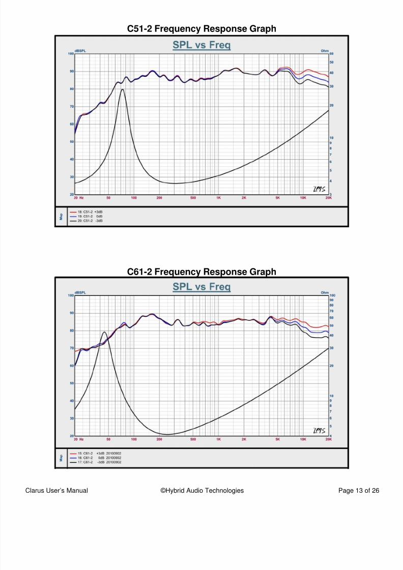
The following six pages contain mechanical drawings of the Clarus C51-2, C61-2, C2x, C1, and tClarus accessory tweeter hardware, as well as frequency response graphs1 of the C51-2 and C6showing the three steps of tweeter-level attenuation.
1Please note that the response peak at approximately 170 Hz is a testing room mode and is not indicative of the speak
performance at that frequency. All speakers tested show this same phenomenon, and it has been concluded to be a room artifac

5/14/2018 Clarus Manual - slidepdf.com
http://slidepdf.com/reader/full/clarus-manual 8/26
Clarus User’s Manual ©Hybrid Audio Technologies Page 8 o
Clarus C51-2 Mechanical Drawing

5/14/2018 Clarus Manual - slidepdf.com
http://slidepdf.com/reader/full/clarus-manual 9/26
Clarus User’s Manual ©Hybrid Audio Technologies Page 9 o
Clarus C61-2 Mechanical Drawing

5/14/2018 Clarus Manual - slidepdf.com
http://slidepdf.com/reader/full/clarus-manual 10/26
Clarus User’s Manual ©Hybrid Audio Technologies Page 10 o
Clarus C2x Passive Crossover Mechanical Drawing

5/14/2018 Clarus Manual - slidepdf.com
http://slidepdf.com/reader/full/clarus-manual 11/26
Clarus User’s Manual ©Hybrid Audio Technologies Page 11 o
Clarus C1 Tweeter Mechanical Drawing (Installed in Flush-Mount Cup)

5/14/2018 Clarus Manual - slidepdf.com
http://slidepdf.com/reader/full/clarus-manual 12/26
Clarus User’s Manual ©Hybrid Audio Technologies Page 12 o
Clarus C1 Tweeter Mechanical Drawing (Installed in Angle-Mount Cup)
5/14/2018 Clarus Manual - slidepdf.com
http://slidepdf.com/reader/full/clarus-manual 13/26
Clarus User’s Manual ©Hybrid Audio Technologies Page 13 o
C51-2 Frequency Response Graph
C61-2 Frequency Response Graph

5/14/2018 Clarus Manual - slidepdf.com
http://slidepdf.com/reader/full/clarus-manual 14/26
Clarus User’s Manual ©Hybrid Audio Technologies Page 14 o
Unpacking/Inventory
Carefully unpack the Clarus carton, and verify that the following parts are included in the b(CAUTION: use care to remove the midbass speakers with two hands, and avoid pressing ythumb or fingers against the cone of the midbass – never test the speaker’s excursion manually wyour fingers by pressing the cone):
• Two Clarus midbass speakers;
• Two Clarus C1 20mm tweeter speakers;• Two midbass grilles with anodized aluminum Hybrid Audio Technologies nameplates and A
grille mounting flanges;
• Four small packages located underneath the midbass drivers, which contain:o Connection wiring with tinned ends for direct connection to the crossovers and polariz
male/female insulated slide connectors for connection to the midbass speakers;o Hardware needed to install the midbass speakers, including high-quality black ox
Philips head screws and black oxide steel “speed clips”; ando Four small slices of butyl adhesive putty to help secure the supplied grilles to the A
grille mounting flanges, if needed.
• Two small packages located underneath the tweeter drivers, which contain:o Connection wiring with tinned ends for direct connection to the crossovers and polariz
male/female insulated slide connectors for connection to the tweeter speakers;o Two angle-mount and two surface-mount fixtures to be used for various twee
mounting options; ando Hardware needed to install the tweeter speakers, including high-quality black ox
Philips head screws and black oxide steel “speed clips.”
Should you be missing parts, please contact your authorized Hybrid Audio Technologies dealer replacement parts, or contact us directly at [email protected].
How to Use This ManualAs mentioned in the Welcome and Introduction, this is not your typical car stereo speaker ownemanual. It is a mobile audio reference manual for not only your impending Clarus installation, but ato act as a guide to get the most out of your audio system. Generally speaking, this manual is dividinto two parts. The first part focuses on a typical, basic installation of the Clarus product, and folloin general what you’d expect from a mobile audio component system owner’s manual. The secopart delves into more advanced topics on optimized speaker placement, “lessons learned” (a topidiscussion of real-world applications), use of sound damping products and acoustic absorptmaterials, and fine tuning. Most users will stop at the conclusion of the first section once the bainstallation is complete, and this is perfectly acceptable. But for those with an intrinsic desire to leamore about how to make their mobile audio systems better, we invite you to continue reading throuthe latter half of the manual as well. Our goal is to not only build the best-performing mobile ausystems in the world, but to also educate consumers and professional installers alike on how achieve reference-grade audio system playback in the mobile audio environment.
Section I - Getting Started – Basic System Installation
Now that you have unpacked the Clarus box and have verified that all of the parts are included, itime to evaluate the vehicle for the impending installation. If you feel the least bit uncomfortable abo

5/14/2018 Clarus Manual - slidepdf.com
http://slidepdf.com/reader/full/clarus-manual 15/26
Clarus User’s Manual ©Hybrid Audio Technologies Page 15 o
the installation, have the Clarus speakers installed by an authorized Hybrid Audio Technologdealer. The Clarus speakers are an incredible high-end speaker system, but will only be as good the installation; a poor installation can negatively affect the performance of the Clarus speakers. Wcan only build great speakers, but can’t control or account for poor or inadequate installations.
Should you decide that you can handle the installation yourself and feel confident that the end reswill be adequate to reap the performance benefits of the Clarus component system, you will needhave certain hand tools available to you for the installation. These include, but may not be limited to
• Cordless drill/driver with a 1/8” drill bit and a Phillips head and a few assorted driver b(commonly including Torx driver bits) with an attachment (a hand-operated screw driver andTorx driver will also likely work);
• Certain vehicles may require an assortment of hex-key wrenches to remove the old speakeand/or panel screws;
• A panel-popping tool (retaining clip removal tool) to remove panels in the vehicle (such as dpanels). In a pinch, a large flat-head screwdriver does work, but damage to panels or retainclips can result;
• A wire cutter and wire stripper;
• Electrical tape; and
• If you plan to use the vehicle’s existing speaker wire, you will need to know which wirepositive and which is negative at each proposed speaker location. If you’re unsure, we higrecommend the use of Installation Excellence, an on-line resource for wire colors, wlocations, fit guides, and technical support.
In a basic system, the Clarus midbass speakers were designed to be installed in the original factspeaker locations, most often in the vehicle’s doors (more advanced locations that provide additional level of performance are discussed in Section II of this manual, if you’re interestedlearning more). The Clarus midbass drivers are infinite baffle-capable speakers, and must mounted in a “large enclosure”, or as close to it as possible, with unrestricted access to airspaceensure the speaker’s ability to effectively reproduce its wide frequency bandwidth. The reason wthe speaker was designed in this way is highly empirical. When a speaker is mounted in a smclosed box, it radiates as much energy forward of the cone as it does rearward of the cone. speaker cones (diaphragms) are a weak sound barrier at best, and the result of the high amountenergy being “pushed” into a small enclosure is the energy transmitting through to the outside of cone (an additive phenomenon to the incidental wave). Consequently, Hybrid Audio has designed tClarus midbass to work well without an enclosure, and as such, should not be significantly proneenclosure back-pressure and sound coloration when placed infinitely baffled. The “infinitely larenclosure, such as one might find in a door panel, improves spectral response and power responvariation between high and low frequencies.
In a basic system, the Clarus tweeters were designed to be installed in factory-supplied tweelocations, typically found in the a-pillar, dashboard, sail panel, or door panel. If your vehicle is oldor did not come with factory tweeter locations, you may need to install the tweeters in a bit ocustom fashion. Not to fear though – we have included several different options for easily mountthe tweeters, so you can decide which will work the best for your application. Since the tweeters arsealed-back design, they can be placed anywhere without having to provide airspace or any typeenclosure. Hybrid Audio Technologies highly recommends that the tweeter placement be the subjof your own experimentation. This can be accomplished by leaving some excess wire length for tweeter, and experimenting with different potential mounting locations by temporarily attaching tweeter using double stick tape, Velcro ® , etc.

5/14/2018 Clarus Manual - slidepdf.com
http://slidepdf.com/reader/full/clarus-manual 16/26
Clarus User’s Manual ©Hybrid Audio Technologies Page 16 o
An important learning note! Hybrid Audio Technologies designed the Clarus-series to be configuwith the tweeter relatively close to the midbass, such as within 30cm or so, as we can effectivmitigate anticipated environmental conditions and reduce the number of variables in this typeinstallation. When the tweeter and midbass are placed close to each other, the relative amplitud(volumes) of the midbass and tweeter are equalized to each other and the speaker system perform as intended. When the tweeter is separated by a far distance from the midbass, the relatamplitudes will likely need to be equalized. This is due to simple physics. If the midbass drivers placed low in the door, for example, and the tweeter is placed high in the dashboard, sail panels, or
pillars, there WILL be a notable amplitude difference between the two speakers. This is because midbass are installed further from you, and are likely aimed into your leg, carpeting, and other sfurnishings in the vehicle, while the tweeter is located likely closer to you, likely aimed more “ox-axand is near hard, reflective surfaces, such as window glass, hard plastic interior panels, and etc.
One of the benefits of the Clarus series over its sibling Imagine series is the inclusion of an outboacrossover system that includes a fairly comprehensive set of attenuation filters for the tweeter outpWhereas the Imagine systems do not include any form of filtering to attenuate the tweeter’s relatamplitude with respect to the midbass, the Clarus sets do come with the feature of a steppattenuation network to satisfactorily allow for the end-user to tune and customize the tweeter’s lewith respect to the midbass. The tweeter attenuation network allows for a world of potential n
mounting possibilities of the tweeter location with respect to the midbass location.Finally, just because there is a factory tweeter pod location in the dashboard, a-pillars, or sail panin your vehicle doesn’t mean you have to use it! Because our ears are on the left and right sidesthe human head, human hearing is much less susceptible to hearing height cues as it is hearing wiand depth cues (please reference Lesson 3 and Lesson 4 later in this manual). Please don’t be foointo thinking that the tweeters MUST be placed high in order to establish a good stage height! Alas the end-user, it is up to you to take the time and test the set to see what orientation is to yoliking, and certainly, as students of acoustics, we at Hybrid Audio Technologies encourage tlearning exercise.
Installation
Once you have determined the mounting locations for the Clarus separates, and have evaluated circumstances by which the Clarus speakers will need to be installed, it is time to dismantle tvehicle to access the old speakers. Most dashboard-mounted speakers are easily accessed removing their grilles, which are usually attached to the dashboard with screws or retaining clips.pillars are usually accessed by pulling firmly at a right angle to the panel. Door speakers are usuaeasy to access as well, either from the front by prying off the OEM grille, or by physically removthe entire door panel. In all cases, it may be prudent to reference your vehicle’s factory servmanual. If you don’t have a factory service manual, you can go to the Installation Excellence websfor downloadable resources with respect to not only wiring but disassembly of your vehicle, and tprocedures to access your OEM speakers.
With the OEM speakers removed, we HIGHLY recommend the use of a self-adhesive dampproduct, such as brand names Dynamat ® , B-Quiet ® , RAAMmat ® , and others. The reason for the uof damping material is to quiet buzzes and rattles that will be exposed by the high-performanClarus midbass speakers, but more importantly to seal up door accesses and cavities, therecreating a pseudo “enclosure” for the Clarus midbass. If the midbass are installed immediatadjacent to a large access hole or opening in the door panel, there will be an acoustic “short circu(as described later in “Frequency Response”) where the front and back waves of the speaker meand cancellation will occur, seriously affecting midbass output. The use of a good damping producthe single-biggest installation-related improvement you can do to enhance the performance of y

5/14/2018 Clarus Manual - slidepdf.com
http://slidepdf.com/reader/full/clarus-manual 17/26
Clarus User’s Manual ©Hybrid Audio Technologies Page 17 o
Clarus audio system. And since the Clarus midbass require an “infinite baffle”, it is intuitive to sealthe mounting area as best as possible, such as in the door, allowing the speaker to “see” a laenclosure in the door cavity, kick panel, dashboard, or wherever you decide to mount the Clamidbass.
If you plan to use the OEM speaker wiring, you will likely need to cut off the OEM speaker plug, astrip back approximately 3/8” (10mm) of insulation to expose the bare wire. It is recommended tyou then install slide-style terminals on the wire, for easy connection to the Clarus midbass.
In a basic installation, the Clarus midbass were designed to install directly into the factory-supplspeaker baffles or speaker openings. The speaker should fit snug to the baffle without air gaps; not force the speaker into a baffle that is too small, as this will damage the speakers. If the factosupplied mounting baffle is too small, refer to Section II for advice on how to build custom bafflWhen tightening your speakers to the baffle, alternate the tightening of the screws, just as if you wechanging a tire on your vehicle, by alternating in a pattern around the speaker until all screws ahand-tight. DO NOT INSTALL THE SPEAKERS WITH A DRILL OR DRILL-DRIVER, as the drill-drwill put considerably more torque on the speaker basket than what is required, and can easdamage the frame of the speaker.
The same procedure can be followed for the tweeter installation observing the precautions mention
in the midbass installation, above. Once a suitable location is found for the tweeters, mountoptions can be evaluated. The Clarus kit comes standard with three tweeter mounting optioincluding a swivel flush-mount cup, a surface-mount cup, and an angle-mount cup. Decide whmounting strategy works the best for your installation, and permanently mount the tweeters. Rothe wiring from the underside of the tweeter to an accessible location. At first, connect the tweewire to the 0 dB terminal location on the passive crossover to the positive terminal (red wire) of tweeter, and the negative (black wire) from the TW- terminal on the passive crossover to the tweetenegative wire. The wiring is color coded and the terminals are keyed according to gender, convenience. The -3 dB, 0 dB, and +3 dB all reference various output levels for the Clarus tweeso you can fine-tune your system’s treble amplitude (loudness) with that of the midbass drivers.
Once all four speakers are installed, you will need to do a brief listening test with CD-quality muthat you are intimately familiar with to determine if the tweeter attenuation of 0 dB is adequate for yolistening style, type of music you listen to, and the acoustics and speaker locations and relatintensities of the speakers as they interact with your vehicle. In most systems, the -3 dB or 0 setting will be the preferred choice. In certain instances, and for certain owner’s, the +3 dB settmay be a good option. Be sure that all equalization, bass, and treble levels are defeated or se“zero” on the source unit before evaluating the intensity of the tweeters with respect to your midbalevel and your listening taste. Note also, after approximately 10-25 hours of play time, the speakwill begin to “break in”, like any mechanical component, and intensities may need to be re-adjustagain following the same procedure. In other words, the midbass need to be broken in with typplay-time. You may find that after break-in, the tweeter intensity will need to be adjusted.
Once levels are set as per the above, the sound damping cropped so as to allow for the re-installatof door panels and/or interior panels, and all wiring neatly wire-tied away from heat and nosources, or from abrasion and areas where the wires may be accidentally sliced or cut, the vehican be re-assembled. Sit back and enjoy the music.
This is the end of Section I: Basic Installation. If you’re happy with the end product, stopreading here. If you want to learn more about advanced techniques for achieving great mob
audio sound quality, flip the page!
5/14/2018 Clarus Manual - slidepdf.com
http://slidepdf.com/reader/full/clarus-manual 18/26
Clarus User’s Manual ©Hybrid Audio Technologies Page 18 o
Section II - Moving Forward – Advanced System Installation
The previous section detailed a typical, basic installation of the Clarus product. In this section, HybAudio Technologies has prepared a more advanced topical discussion of Clarus installattechniques, concepts, and principals, where a little bit of additional installation work can net immengains in overall sound quality.
There are certainly many things you can do to improve your mobile audio system, such as additionamplification, a dedicated subwoofer system, higher-gauge speaker wire, and higher-end passcrossovers, and active crossovers. All of these things require an additional amount of monetainvestment into your audio system, and may not net the immediate gains that other, more elementainstallation items can net. The following discussion is pertinent to easy and cost-effectenhancements you can do for your audio system, particularly as it relates to the installation of Clacomponent speakers.
In any mobile audio system, the weakest link will always be the speaker systems, followed closelyinstallation techniques (sometimes its vice-versa). Since the Clarus component system you hapurchased has solved the first issue, the second issue, that being installation techniques, can seesignificant improvement as well by understanding and incorporating some or all of the techniquesthe following sections.
Lessons Learned
We like to call this our “Lessons Learned” section, where we expose some critical lessons that have learned through thousands upon thousands of hours of trial and error:
Lesson One: Off-Axis Response
When a speaker system like the Clarus is placed in an automotive environment, we hear the dir(shortest path) and reflected (longer path) sounds, such as resonances and reverberations. The tsounds are processed by the brain as one sound, and this influences our perception of height, widand depth of soundstage, as well as rearward ambience. For this reason, the off-axis radiation patteof any speaker in a vehicular environment has a significant influence on how natural the musounds.
The lesson to learn here is that most mobile audio sound systems benefit greatly from having front stage speakers at least partially “off-axis.” Off-axis means that the speakers are not pointingyou, but rather at some angle less than 90 degrees away from you.
Lesson Two: Equalization of Pathlength Differences
Quite possibly the most important functional consideration that a do-it-yourself enthusiast professional installer should give to the Clarus speaker placement is to optimize, as best as possibpathlength differences (PLD’s) in the vehicle. PLD’s are defined mathematically as follows (texample assumes a right-hand drive vehicle---PLD’s are always a positive number):
X – Y = Z
5/14/2018 Clarus Manual - slidepdf.com
http://slidepdf.com/reader/full/clarus-manual 19/26
Clarus User’s Manual ©Hybrid Audio Technologies Page 19 o
Where:
X = distance of the center of the left speaker from your left ear.Y = distance of the center of the right speaker from your right ear.Z = pathlength difference.
Applying this formula, assume that the distance of the left speaker from your left ear is 140cm, athe distance of the right speaker from your right ear is 100cm, the pathlength difference is 40cm.
Good stereo imaging is completely dependent on arrival times of the fundamental vocal frequenciDifferences as little as 10 micro seconds can be detected by the brain. A PLD of 30 centimetequates to the sound from the nearest channel arriving about 0.9 milli seconds earlier than the furthchannel. It is Hybrid Audio’s opinion that the end-user should try to keep PLD’s to less than centimeters in a vehicle which is intended to have good imaging and staging character from boseated positions.
The best way to go about evaluating certain locations in your vehicle is, in general, to look for tpotential locations as far forward and away from you as possible, but still with a general “line of sigto the speakers (particularly the speaker on the far side of the vehicle). An easy way to test vario
potential locations is to hold a tape measure or other measurement device from the potential speamounting locations, and measure those locations with respect to your ears.
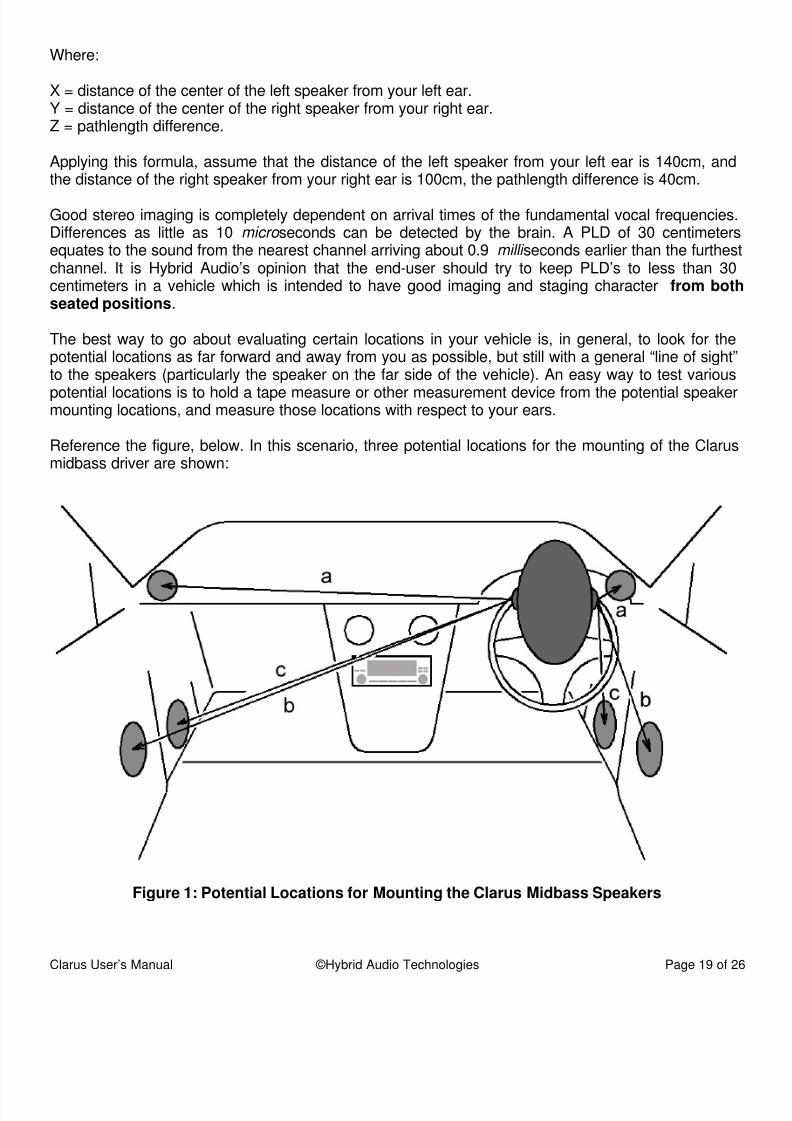
Reference the figure, below. In this scenario, three potential locations for the mounting of the Clamidbass driver are shown:
Figure 1: Potential Locations for Mounting the Clarus Midbass Speakers

5/14/2018 Clarus Manual - slidepdf.com
http://slidepdf.com/reader/full/clarus-manual 20/26
Clarus User’s Manual ©Hybrid Audio Technologies Page 20 o
In scenario “a”, we show the installation of the Clarus midbass in the dashboard, high in a door panor in the a-pillar. As you can see from the diagram, the PLD’s between the left and right speakers large, due to the proximity of the listener to the near-side speaker. While the mounting of primdrivers in the dashboard or a-pillars has become increasingly popular, this configuration undoubtedly require both time and intensity domain equalization in most vehicles to ensure a gofocused center image, properly located in the center of the vehicle for one seated position. Thare, however, some rare exceptions, and you may actually find that the dashboard locations provthe best equalized PLD of the available mounting locations; this is very rare though – in o
experience, less than one percent of vehicles on the market today have optimized dashboard spealocations for the midbass drivers.
In scenario “b”, a typical door installation location is shown, and in many vehicles represents a goimprovement in PLD’s from the dashboard, high in the door panel, and a-pillar location identifiedscenario “a.” The door speaker installation scenario is the one detailed in the basic installation sectat the beginning of this manual, and in most vehicles represents a satisfactory location to mospeakers; not ideal but satisfactory. The door speaker installation scenario will likely also requsome amount of time and intensity equalization to ensure a centered image in most vehicles; this cbe as simple as adjusting the balance control on your source unit, to more advanced ways of digtime and intensity manipulation.
The third and final potential mounting location as shown in this diagram (scenario “c”) representskick panel installation, where the midbass are placed far forward in the A-frame cavity of the kpanels, present in most vehicles. The kick panels are the small panel next to the throttle and brapedals, down by your feet. While it is not immediately obvious looking at a two-dimensional drawiin many cases the kick panel location affords the best equalization of pathlength differences for mvehicles. And the reason why this is a good choice for most vehicles is defined in the second paragraph of Lesson Three, below.
The lesson to be learned here is that by taking a few moments to evaluate the potential mountlocations in your vehicle, in a very short period of time, you will be able to find the best location
your Clarus midbass by determining the location with the smallest PLD.
Lesson Three: The Effect of HRTF, ITD, and IID
Head-related transfer function (HRTF), interaural intensity differences (IID), and interaural time de(ITD) all play a key role in the optimum placement location for the Clarus component speakerssound wave approaching the eardrum from your chosen speaker location is shaped by interactiowith the size and shape of your head, torso, and outer ear, resulting in the HRTF. More specificathe HRTF is the ratio between the sound pressures of the wave at the eardrum, as compared to sound pressure that would exist at the center of the head if the head were removed. In general, tsound arriving at the ear further from the source is attenuated and delayed relative to the sou
arriving at the ear closer to the source. This generates an interaural intensity difference (IID) and interaural time delay (ITD). As a sound approaches the head, the ratio of distances from the speaklocation to the near and far ears increases, and the effects of head-shadowing are amplified, causthe IID to increase. The spectral shaping caused by the head and the shape of the outer ear may achange. The ITD, which results from the absolute difference in path length from the source to tears, remains approximately constant as distance decreases. From this we learn:
• ITD is the dominant factor for frequencies below about 500 Hz;

5/14/2018 Clarus Manual - slidepdf.com
http://slidepdf.com/reader/full/clarus-manual 21/26
Clarus User’s Manual ©Hybrid Audio Technologies Page 21 o
• A combination of ITD and IID are dominant for frequencies between approximately 500 Hz a2,000 Hz; and
• IID, in concert with HRTF, are dominant above about 2,000 Hz.
These are generalizations, and are subject to the size and shape of one’s head and torso, and sand shape of the outer ear (the folds and ridges of the ear), but in general, the above is a goguideline for establishing ITD, IID and HRTF thresholds for the human auditory system.
Because the Clarus midbass’ ability to play into the sub-200 Hz range, an effect clearly dominatedITD, up to and including frequencies exceeding 6,000 Hz, an effect clearly dominated by IID aHRTF, placement of this driver is extremely important. The driver should be placed as far forward possible in the vehicle to optimize ITD. Lateral (forward to back) placement is much more importathan horizontal placement (up and down). This is because of the brain’s ability to process sounsuch as spectral envelope cues, and use a phenomenon known as the “precedence effect”; the brcan be easily “fooled” into thinking a sound stage is high with kick panel or floor-mounted speakersword to the wise: the best place to put a set of speakers is not always “up high”, as most vehiclesnot offer an amicable location in the dashboard or a-pillars for good image placement for both seatpassengers, especially in the critical frequencies sub-500 Hz). In addition to the time equalizplacement of the drivers, the end-user must also consider that above approximately 2,000 H
intensity plays a key role in good sound staging and imaging. Therefore, the Clarus midbass’ shobe placed in an area where intensity differences can be equalized, either mechanically electronically, to ensure good imaging and sound staging.
The lesson to be learned is that, like Lesson Two, the Clarus midbass should be placed as forward from your listening position as possible, and every effort should be made to optimize time aintensity domain characteristics of the installation.
Lesson Four: Point-Sourcing
The term “point-sourcing” is often used to describe the technique of having a single pair of speak
in an installation cover the majority of the critical middle band frequencies. In many installatscenarios, the Clarus midbass could be considered a point-source speaker driver, because it has ability to reproduce six octaves of tones. Point-sourcing, if done correctly, can lend itself to a variof valuable attributes, including precise image definition and stable sound staging character. applying Lessons 1-3 above, the Clarus midbass can be used as a point-source driver to achieexcellent staging and imaging results.
The lesson to be learned here is that the Clarus midbass, given its wide-bandwidth design, cfaithfully reproduce as much as six octaves of tones, and would make a valuable addition to asound system as a point-source driver for the spectrum comprising vocal imaging cues.
Lesson Five: Reference
One of the most important things to do before completing your Clarus installation is to get a referenfor your future listening tests. To really know what a snare drum sounds like, you must go and listo one, in person, live and un-amplified. There is no substitute for the visceral impact and emotionlive music. Nothing else in life can touch your soul the way music does. Whether it’s a 200-memborchestra, or a four-piece fusion band, nothing compares to the phenomenon of live music.

5/14/2018 Clarus Manual - slidepdf.com
http://slidepdf.com/reader/full/clarus-manual 22/26
Clarus User’s Manual ©Hybrid Audio Technologies Page 22 o
Take this as Hybrid Audio’s official request: become a student of music and your mobile audio sousystem will be better for it. We want nothing more than to know there are great sounding ausystems around the world using our products, and you’d make us all very proud if you becamestudent of music and learned its beauty and passion.
Advanced Installation of the Clarus Component Systems
Mounting Baffle Considerations
Now that we have revealed five of our most important “Lessons Learned”, we can now apply thelessons to the Clarus installation. The first important matter is the physical installation of your Clamidbass, and more specifically with respect to improving the Clarus midbass’ mounting baffles. Mvehicles’ factory mounting locations for speakers are less than ideal. In most cases, the OEM speamounting flanges are likely nothing more than flimsy extruded plastic, and provide no sonic benefityour Clarus installation. The Clarus drivers are long-throw midbass, and the plastic mounting baffthat come from the factory in virtually every vehicle will lead to buzzes, rattles, vibrations, aresonances, all of which negatively affect the Clarus installation. In other vehicles, you may haattached the Clarus midbass’ directly to the door metal (hopefully with a layer or two of self-adhessound damping in between), but this is still not entirely ideal. In whatever scenario you have instalyour Clarus midbass, there are certain “tricks” and techniques that may be applied to get the most oof your Clarus component set, specifically the midbass installation, as follows:
Mounting the baffle, sound damping, and “decoupling”: the mounting baffle or mounting locatshould either be secured extremely well to the vehicle’s body, or completely isolated from vehicle’s chassis. The reasoning is that the speaker baffle panel will vibrate and will radiate souEven small vibrations can result in the baffle itself radiating more sound than the actual speakercertain frequencies. The mounting baffle or mounting location should be damped with a layer typical sound damping to reduce the Q of the baffle and lower its vibration resonance frequenbelow the range of the driver’s frequency response. In many cases, using thicker baffle paneconcert with self-adhesive sound damping can also be advantageous, provided the rearward wave
the speaker has no obstructions created by the baffle itself. Finally, if possible, the speaker shouldmechanically decoupled from the baffle. This can be something as simple as a layer of self-adhesfoam tape, to more exotic examples of decoupling, including rubberized rings or multiple-layer septshielding.
Building solid mounting baffles: in many cases, it is advisable to mount your Clarus midbasshigh-stiffness wood or high-density fiberglass (or wood treated with fiberglass resin). Hybrid AuTechnologies recommends the use of a solid hardwood, such as birch or oak, namely because thewoods are stiff and help to dissipate resonance, and screws can be inserted and removed multitimes without stripping. Avoid Medium Density Fiberboard (MDF), particularly in wet environments lthe door, as the MDF will act like a sponge with humidity and moisture, and not only that, the MDF
a dense, but not stiff type of wood, and the results may not be particularly noticeable if you use MDOnce your baffle is built, it must be covered in one or two layers of a good-quality, brand name sadhesive damping product; a solid wood mounting baffle with sound damping treatment will augmthe Clarus installation by eliminating resonances.
Mounting baffle dimensions: While building baffles is important, it is notable that mounting basize is equally important. All mounting baffles should be kept as small as possible with respect to tsize of the speaker. The purpose of using a small baffle is to avoid the potential for low amplitudiffracted sound waves becoming summed with the incidental waves. A narrower baffle also becom

5/14/2018 Clarus Manual - slidepdf.com
http://slidepdf.com/reader/full/clarus-manual 23/26
Clarus User’s Manual ©Hybrid Audio Technologies Page 23 o
increasingly important as frequencies range into the Clarus midbass’ upper bandwidth, where power response is more uniform and incident and reflected waves are indistinguishable. In practiterms, keep baffle dimensions small with respect to the size of the Clarus midbass, chamfer or rousharp edges (including, in particular, the mounting hole’s rear inner edge), flush-mount the speawhenever possible, and use shallow, surface-mounted hardware. Also, remove all unnecessprotrusions from the baffle surface.
Acoustic Treatment
A considerable benefit can be made to any mobile audio system with the select placement of acoustreatments. The purpose of using acoustic treatments is to reduce the amount of reflected energythe hostile automotive environment, and hear more of the direct sound being emanated from speaker. It is akin to the signal to noise (S/N) ratio in a piece of electronics, where the signal could considered the direct energy coming from the speaker, and the noise could be considered reflected waves off of nearby surfaces, such as windows, hard center consoles and door panewindscreens, and etc. A word of warning though: there is a fine line between too little and too muacoustic treatment; just as some vehicles can benefit from some selectively applied treatments, theis a point where the vehicle can begin to approach “semi-anechoic” conditions, and lose its livelinewhich is not ideal. Reflections are all around us, and are a part of our day-to-day lives. It is
opinion that some lateral reflection is a good thing; it helps to establish stage boundaries, and givthe recoded playback and more visceral and “believable” sound.
The first principle to understand is that below 200 Hz, acoustic treatments are rendered virtuauseless. It is Hybrid Audio’s assertion that only those frequencies above 200 Hz benefit from the uof treatments, given that a 200 Hz waveform is about 1.7 m long; 1.7 meters is less than or equalmost vehicle widths. This is also the frequency where we believe pure tones in the vehicle are goto be difficult, if not impossible to localize. Finally, most vehicles exhibit a Schroeder Frequency (between 50 at 125 Hz; the Fs (or cabin-gain frequency) is vehicle dependent, and is the frequencywhich resonances become so tightly packed in frequency and space that the acoustical propertiesthe vehicle behave quite uniformly. (As an aside, one significant benefit of car audio sound syste
is that frequencies below the lowest room resonance increase at a theoretical 12 dB/octave…it’s wonder car audio systems have such great bass!)
Acoustic treatment can be very effective above 200 Hz, depending mostly on the polar radiatpattern of the speaker. In the case of the Clarus midbass, the polar radiation pattern is quite largelower frequencies, with a narrowing of the radiation pattern (“beaming”) at frequencies into the trebandwidth.
Should the Clarus midbass be placed in the kick panel locations, one may find that a notaimprovement can be made by adding acoustical treatments, such as open-cell foam, into tunderside of the dashboard. Likewise, should the midbass, or in fact the C1 tweeter be placed
high on a-pillars, or in the dashboard, where comb filtering (reflective summation and cancellation of a hard surface, such as a windscreen) may become an issue, a dashboard “mat” or other sfurnishing may be a noticeable improvement. It will require trial and error to get it right, but learning is in the experimentation!

5/14/2018 Clarus Manual - slidepdf.com
http://slidepdf.com/reader/full/clarus-manual 24/26
Clarus User’s Manual ©Hybrid Audio Technologies Page 24 o
Advanced Installation Conclusions
Sadly, there are no rules in mobile audio, only several hypothesis and theorems that seem to work most vehicles. Your vehicle may be different, and defy everything we know, and everything writtenthis manual. You may find that getting that rich, detailed sound that you crave may require soexperimentation and a lot of work to make it right. Or you might be fortunate to have a vehicle tsounds excellent with minimal work. Have patience and work through the issues; the result will berewarding musical experience in your vehicle! Just remember, it is critical to get a reference,
detailed in Lesson 5. Go out and become a student of music and audio, learn, and improve yoaudio system one step at a time. The journey is exciting and rewarding!
What we have included above is only a very brief primer to the world of high-end mobile ausystems. We invite you to read more by going to our downloads page at www.-hybrid-audio.com.

5/14/2018 Clarus Manual - slidepdf.com
http://slidepdf.com/reader/full/clarus-manual 25/26
Clarus User’s Manual ©Hybrid Audio Technologies Page 25 o
Warranty
Hybrid Audio Technologies extends a limited one year warranty to the original purchaser, certifythat this product will be free from defects in materials and workmanship under normal and proper ufor one year from the date of purchase.
Hybrid Audio Technologies’ responsibility under this warranty is limited to replacing or repairing,Hybrid Audio Technologies’ option, products or parts determined by Hybrid Audio Technologies to defective either in materials, or workmanship. To attain warranty service, the customer must delithe product or the defective part(s), appropriately packed with proof of purchase date, to authorized Hybrid Audio Technologies dealer. In the event that a direct return from a consumerrequired, the consumer must obtain from Hybrid Audio Technologies a return authorization numband ship the defective product directly to Hybrid Audio Technologies. All shipping expenses are customer’s responsibility. If the product has been updated or superseded, a replacement will be mawith a current model of the same quality and function. Warranty of the replacement parts is limited90 days or the unexpired portion of the warranty period of the product on which the parts are beused, whichever is longer.
This warranty does not cover any defects or costs caused by: (1) modification, alteration, repairservice of this product by any persons or company other than Hybrid Audio Technologies; (2) physiabuse to, overload of, or misuse of, the product or operation thereof in a manner inconsistent with tuse indicated in the instructions; (3) any use of the product other than that for which it was intendor (4) shipment of the product to Hybrid Audio Technologies for service. This warranty does not covlabor costs.
Hybrid Audio Technologies is not liable for any special incidental or consequential damagincluding, but not limited to, personal injury, property damage, damage to or loss of equipment, loof profits or revenue, costs of renting or buying replacements and/or any other additional expenseven if Hybrid Audio Technologies has been informed of the prospect of such damages. Any exprewarranty not provided herein, and any remedy which other than the warranty contained herein migarise by inference or operation of law, is hereby excluded and disclaimed including the implwarranties of merchantability and of the fitness for a particular purpose.

5/14/2018 Clarus Manual - slidepdf.com
http://slidepdf.com/reader/full/clarus-manual 26/26
Clarus User’s Manual ©Hybrid Audio Technologies Page 26 o
Thank You!
Hybrid Audio Technologies is delighted that you have chosen a Clarus component system for yohigh-end mobile audio sound system. We are convinced that a great product offering, backed up wunsurpassed customer service and technical support will advance the Hybrid Audio Technolognamesake in the coming years. We are pleased that you have joined us in our “new generation of car audio.”
If there is anything we can do to help you get the most out of your Clarus installation, please do nhesitate to contact us at [email protected], or by visiting us at www.hybrid-audio.com!


