Clamp-on Ultrasonic Flowmeters - Siemens · The clamp-on ultrasonic flow meter with a thermal...
4
usa.siemens.com/clamp Clamp-on Ultrasonic Flowmeters How they measure up Not cool enough in summer. Not warm enough in winter. Guests staying at a prestigious country club in New York state complained regularly about the air conditioning and heating of their luxury suites and apartments. The geother- mal heat exchange system serving this facility had never, in fact, been fully functional. The system’s maintenance staff had witnessed pump shutdowns as well, with the pumps simply, unexpectedly ceasing to work. Resetting the entire system seemed to be the only way to get them up and run- ning again. Ultimately, a better solution was found. A balancing com- pany was brought in to correct system efficiencies. Utilizing a clamp-on ultrasonic flow meter, company engineers were able to investigate the ground water loops, spot the sources of trouble and make decisions that would save the country club more than $100,000 a year in utility bills. Clamp-on ultrasonic flow meters are valuable tools for helping district energy providers, building owners and managers, and others measure and manage their system performance in a number of ways. These units provide the baseline and load profile information needed to effectively optimize sys- tem efficiency and reduce energy consumption – and costs. Versatile, economical solution While other flow measurement technologies (e.g. magnetic or vortex flow meters) are also used in district energy appli- cations, clamp-on ultrasonic flow meters are often an opti- mal solution since they are externally mounted.They are especially well-suited for use with existing hot- or chilled- water distribution lines. In existing applications they are quick, easy and less expensive to install than other flow meter options because there is no need to cut the line, interrupt service, or drain the pipe. They also do not require the installation of bypass piping and valves for removal; maintenance expense is minimized since they do not have moving parts; and, used outside the pipe, they do not require periodic cleaning.
Transcript of Clamp-on Ultrasonic Flowmeters - Siemens · The clamp-on ultrasonic flow meter with a thermal...
usa.siemens.com/clamp
Clamp-on Ultrasonic FlowmetersHow they measure up
Not cool enough in summer. Not warm enough in winter. Guests staying at a prestigious country club in New York state complained regularly about the air conditioning and heating of their luxury suites and apartments. The geother-mal heat exchange system serving this facility had never, in fact, been fully functional. The system’s maintenance staff had witnessed pump shutdowns as well, with the pumps simply, unexpectedly ceasing to work. Resetting the entire system seemed to be the only way to get them up and run-ning again.
Ultimately, a better solution was found. A balancing com-pany was brought in to correct system efficiencies. Utilizing a clamp-on ultrasonic flow meter, company engineers were able to investigate the ground water loops, spot the sources of trouble and make decisions that would save the country club more than $100,000 a year in utility bills.
Clamp-on ultrasonic flow meters are valuable tools for helping district energy providers, building owners and managers,
and others measure and manage their system performance in a number of ways. These units provide the baseline and load profile information needed to effectively optimize sys-tem efficiency and reduce energy consumption – and costs.
Versatile, economical solution
While other flow measurement technologies (e.g. magnetic or vortex flow meters) are also used in district energy appli-cations, clamp-on ultrasonic flow meters are often an opti-mal solution since they are externally mounted.They are especially well-suited for use with existing hot- or chilled-water distribution lines. In existing applications they are quick, easy and less expensive to install than other flow meter options because there is no need to cut the line, interrupt service, or drain the pipe. They also do not require the installation of bypass piping and valves for removal; maintenance expense is minimized since they do not have moving parts; and, used outside the pipe, they do not require periodic cleaning.

Clamp-on ultrasonic meters are also very versatile: They can be installed on the full range of district energy line sizes (and more – from 0.5” up to 394”), employed anywhere in the hot- or chilled-water distribution process and used to mea-sure two applications simultaneously. They may be installed where an “intrusive” flow meter is not possible or appropriate – when only temporary measurements are needed, for exam-ple. All measurements can be logged and time-stamped for creating analyses and reports.
How they work
The clamp-on ultrasonic flow meter with a thermal energy calculator consists of a flow display computer, ultrasonic-clamp-on transducers, and mounting hardware and cables. Configurations can also include temperature sensors for calculating energy consumption. Clamp-on ultrasonic flow meters utilize either transit-time or Doppler technology – or in some cases, both.
Figure 1. Ultrasonic Transit-Time Flow Measurement.
Transit-time measurement is primarily used on “clean” liquids that do not contain high percentages of solids or entrained air. Transit-time (or time-of-flight) meters are designed on the principle that sound travels faster when moving in the same direction as the flow and slower when traveling in the opposite direction. This technology measures the indepen-dent travel times of sounds transmitted in each direction between two transducers positioned upstream and down-
Figure 2 Ultrasonic Doppler Flow Measurement
stream (Figure 1). Using this information, the flow meter can compute fluid velocity. By subtracting the computed fixed times within the transducers and pipe wall from the measured average transit time, the meter can infer the required transit time in the fluid. The difference in upstream and downstream time is proportional to the fluid velocity. Transit-time ultrasonic meters have diagnostic capabilities that other flow technologies do not. By measuring the speed of sound of the fluid, they can report changes in fluid temperature or other properties. For example, if 42° F chilled water with a speed of sound of 1,429 meters per second (4,688 ft per second) has glycol added, the speed of sound will change. This speed of sound measurement can be used as a direct measurement of the percentage of glycol in water. Another transit-time diagnostic, which is a unique feature of all Siemens clamp-on models, is the indication of entrained air in hydronic systems. This diag-nostic can alert operators to problems within their systems that, if undetected, could damage valves and reduce overall system efficiency due to poor heat transfer.
Doppler measurement, on the other hand, is used when gas bubbles or suspended solids are present in the fluid. Dop-pler units can measure particle sizes as small as 10 microns. The required concentration of gas bubbles or solids that dictate Doppler use will vary based on pipe size, particle size, and fluid velocity. This metering technique relies on the reflection of the sound energy off the bubbles or par-ticles to create a Doppler shift in the fixed-frequency acous-tic transmit signal (Figure 2). The frequency shift is propor-tional to the fluid velocity.
A Doppler ultrasonic flow meter would be used, for example, as a diagnostic tool if a hot- or chilled-water line contained too much air for the transit-time signal to get through to the other transducer (such as if the line is heavily aerated due to pump cavitation or high percentages of glycol).
Transit-time and Doppler technologies can be used in the same application when a process changes from clean to aerated at different times. This is the case when glycol is added to chilled-water lines for freeze protection as these lines may foam periodically and cause transit time measure-ment to fail. Some clamp-on ultrasonic flow meters incor-porate transit-time and Doppler capabilities, enabling users to make all required measurements with one unit.
Clamp-on ultrasonic flow meters like this unit can be used to measure
hydronic flow anywhere along the loop.
Clamp-on ultrasonic flow meters are especially well-suited for use with existing hot- or chilled-water distribution lines.
Multiple applications
Since they can be installed anywhere along district energy distribution pipelines, clamp-on ultrasonic flow meters have the flexibility to be used to balance a hot or chilled-water system, improve chiller performance, indicate direction of flow or measure thermal energy use.
Balancing flows
Prior to clamp-on flow meters and transit-time technology, balancing flows throughout a building was done by only read-ing flows at the circuit-balancing valve. The balancing valves provide pressure taps, and a differential pressure manometer is used for proportional flow correlation. One disadvantage of balancing valves is that they are not always located on the line where critical measurements need to be made.
Clamp-on meters may be used anywhere on the line, and dual- channel models are available to measure two pipes simultaneously. These units can be used to balance systems as well as to verify a hot or chilled-water system’s overall performance. Using measurements taken at various locations along the heating or cooling loop, system operators can ensure that energy is distributed properly. When this is the case, systems often find they can reduce their hot and chilled-water production – saving energy and operating costs, as well as reducing the need for additional maintenance and/or equipment.
In district cooling plants, channel one can measure the chilled water while channel two measures condenser water. This information enables operators to regulate the flow to design conditions. In cases where a main pipe is not acces-sible, measurements may be taken on two branches, which the meter can then add to get the total flow in the main. For a two-branch system, flow can be calculated by measuring main flow and subtracting the flow of branch one from that of branch two. Another example would be measuring the primary, secondary and tertiary flows of a decoupled chiller system. The clamp-on technology can be used very effective-ly to indicate direction and flow rate of the decoupled cross-over connection.
In hot water district heating systems, clamp-on meters can measure the output flow of two boilers simultaneously to balance them. They can also measure the recirculation loop on boilers to ensure that minimum design flow requirements are met; flow below the minimum design standard can pos-sibly cause damage to the boiler.
Improving chiller performance
In addition to balancing systems, the clamp-on meter’s ability to measure two pipes simultaneously makes it useful in assessing how well a chiller/heat exchanger is performing and whether work needs to be done on it to improve efficiency. This is done by measuring the condenser and evaporator flows and temperature using clamp-on transducers and resistance temperature detectors in conjunction with the flow meter.
With the Siemens Sitrans clamp-on meters, in conjunction with the Siemens FEC920 Thermal Energy Calculator, the flow and temperature measurements, along with a kilowatt input, provide operators with a coefficient of performance and energy efficiency ratings. This data can be used to compare chiller performance before and after any mainte-nance is done, which will indicate how much improvement has been made.
Measuring thermal energy use
Clamp-on ultrasonic flow meters can also be used to mea-sure hot or chilled-water use for billing purposes. District energy plants can meter the consumption of customer build-ings, and building owners can submeter their tenants’ ther-mal energy use as well, by floor. The advantage to billing based on each customer’s or tenant’s energy use (as opposed to by square footage or apportionment) is that it allows their individual consumption levels to be projected – which better enables energy consumers to become aware of and curb unnecessary energy use.
In these instances, a revenue-grade unit would be used that measures the flow rate along with the supply and return temperature to calculate BTUs. This type of meter provides an analog or digital output of BTUs or tons. A portable clamp-on meter can be used in addition to verify the accu-racy of permanent meter readings.
The temperature sensors are available as clamp-on or insert types and are precision-matched to 0.02 °F providing a highly accurate delta T reading. Thermal energy measurements are easily made as the flow and temperature elements are “non-intrusive.”
With their versatility in these various applications, clamp-on ultrasonic flow meters can be useful in commissioning or recommissioning buildings or district energy systems, as well as in helping buildings achieve (Leadership in Energy and Environmental Design) LEED® Green Building Rating, System™ certification. In the LEED system, the measurement of hot and chilled-water system flow is required for a building to earn points in the “Energy and Atmosphere – Measurement and Verification” credit category (EAc5) for both existing and new construction. Buildings must provide measurements demonstrating chiller efficiency, boiler efficiency, flows, building usage and the amount of energy used to produce heating or cooling (kilowatts per ton).
Case Study: The Country Club
The clamp-on ultrasonic flow meter proved to be instrumen-tal in optimizing the geothermal district heating system at an upscale New York country club in 2009. A portable Siemens Sitrans FUE1010 (*) unit was used to assess the problematic ground water loops of this 180-vertical-well system, which was the sole source of year-round cooling and heating for the property’s condominium and hotel facility.
In this system, an underground loop exchanges heat be-tween the ground and the water, resulting in the return water being warmer or colder (depending on the season) than the supply water. This water is then fed to 450 water-sourced heat pumps. From its inception, this system had never been operating properly. As a result, the country club
These meters can be used to balance a hot or chilled-water system, improve chiller performance or measure thermal energy use.
received constant complaints from guests that the system did not provide enough heating or cooling. It was, however, not only the guests who were affected by the problems. The plant’s maintenance staff experienced several pump shut-downs at irregular intervals. Resetting the entire system appeared to be the only way to restore operation.
The problem
Using the flow meter, a balancing company soon identified two major problems with the ground source heating system. Using the temperature sensor part of the flow meter, engi-neers measured the temperature of the supply and return water and discovered that the delta T was less than 4 °F. This suggested that there was not enough heat exchange through the vertical ground loop buried approximately 300 feet underground. The water was too hot in summer and too cold in winter.
Measuring the flow of the ground supply and return water, the company found that the flow was at 50 percent of the geothermal heat pump manufacturer’s specifications. The lack of sufficient delta T indicated that the water flow in the underground pipes was laminar (or streamline). Laminar flows can create a thermally resistant, static ‘boundary layer’ of fluid that is in contact with the pipe surface. This layer acts as an insulator, inhibiting efficient heat transfer. The flow rate was simply too low to encourage heat exchange.
The solution
To prevent the insulating fluid layer from forming, the flow rate needed to be increased. This would ensure the creation of turbulent flow in the pipes, allowing optimal heat transfer conditions. The solution entailed making overall changes to the system, including upgrading the secondary water pump used for the underground piping to provide extra thrust. The results were astounding: Delta T was tripled during heating as well as cooling conditions; a significant drop in electricity used to run the pumps was recorded; 35,000-40,000 fewer gallons of fuel oil were used for the supplemental heating system; and the country club guests were more comfortable.
Corrections made to the system saved the country club more than $100,000 a year in utility bills from eliminating both the supplemental fuel oil used during the heating season and the electricity used to cool the rooms during the air condi-tioning season.
Whether tapping geothermal heat or other energy sources, district energy systems will find clamp-on ultrasonic flow meters a useful tool for verifying the performance of energy-generating equipment and optimizing energy load and usage. The portability and non-intrusive nature of this tech-nology allows this to be done without interrupting existing operations. Ultrasonic flow meters enable systems to ‘clamp-on’ to their energy and make decisions that can improve efficiency and save money.
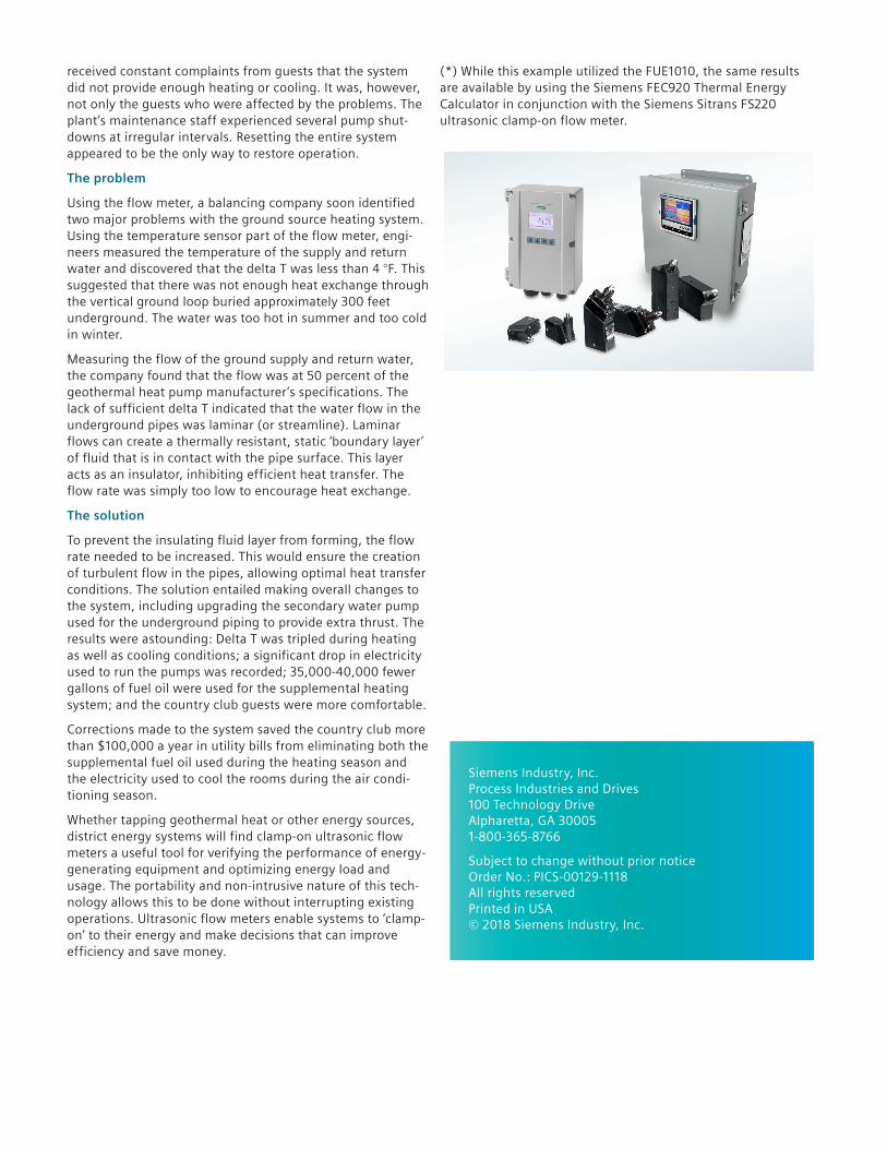
(*) While this example utilized the FUE1010, the same results are available by using the Siemens FEC920 Thermal Energy Calculator in conjunction with the Siemens Sitrans FS220 ultrasonic clamp-on flow meter.
Siemens Industry, Inc. Process Industries and Drives 100 Technology Drive Alpharetta, GA 30005 1-800-365-8766
Subject to change without prior notice Order No.: PICS-00129-1118 All rights reserved Printed in USA © 2018 Siemens Industry, Inc.