NIST Experiences with Multipath Ultrasonic Flow Meters for ...

CLAMP-ON ULTRASONIC FLOW METERS OPERATION AND APPLICATION
WILLIAM E. FRASIER STAFF ENGINEER
CEESI MEASUREMENT SOLUTIONS, INC.
This paper is aimed at ultrasonic natural gas meters that use transit time across the gas pipe as the measurement variable. Custody transfer meters using sensors wetted with gas are the more familiar meter format . Clamp-on meters are quite similar.
General Clamp-on meters are specified to achieve two to three per cent uncertainty. Manufacturers cannot control the quality of a given field installation and must provide latitude. Lab testing has demonstrated most installations perfonn at an accuracy level range of 1%. If a reliable installation technique is maintained. the clamp-on meter will often perform better than manufacturer standards. Further the meter control units have piecewise linear error correction schemes such that they can be adjusted to reference flow rates as afforded at a flow lab.
Clamp-on repeatability is very precise. Often the exact flow volume is not as important as repeatable data before and after an experimental change such as a meter cleaning. Changes as small as 0.1% can be detected.
There is a learning curve or experience effect. New users often have no confidence in the clamp-on technology. Training helps and repeated installation in known settings aids user confidence. Clamping on at a fl ow lab where flow rate is known is helpfuL In fact, a useful application is clamping on a custody meter as it is flow calibrated at a lab and collect clamp-on data
LAM B - WIDE BEAM
at the same time. The clamp-on can later be installed in the fie ld setting and compared to the custody meter to identify shifts between the two meter relationships at the flow lab.
Meter Basics Both wetted sensor and clamp-on meter types send ultrasonic pulses across the gas stream at an angle to sense the flow field . Both use quartz crystal as a sound impulse source.
The difference is the mount. The clamp-on is outside the pipe and is not exposed to conditions within the pipe. It can't be fouled as wetted sensors have a tendency to do.
While wetted sensors are fi xed at an angle to the pipe axis, clamp-on meters rely on physics to establish the angle. There is a bend of the ultrasonic pulse as it enters the gas stream caused by the index of refraction between the steel pipe and the gas within the pipe. The angle across the pipe rather than a nonnal square diameter path is necessary to develop a component of gas velocity in the transit time. The gas velocity traveling downstream makes the transit across the stream faster than simple speed of sound in the gas. Similarly, the moving gas makes transit lime longer when the ultrasonic beam is traveling upstream. In fact the ability to send pulses both downstream and upstream cancels out many gas variables and simplifies gas measurement to just measurement of time.
There are two types of clamp-on transducers, Lamb wave and Shear wave. Lamb wave transducers sometimes called wide beam, are easier to work with. Refer to Figure I.
, , , ' , ' , ' , ' , ' , '
, 0 , ' , ' , " , , , , , ,
SHEAR WAVE
, , ,
Figure L Transducer Types.
The Lamb wave transducer has its crystal parallel to the pipe wall . It produces a large coherent pulse with many rays launched at the same angle. The receiving transducer only needs one of the rays to operate so that exact transducer spacing is not critical.
Shear wave transducers have the crystal nonnal to the pipe wall or sort of vertical. That produces a small beam and alignment is important but this type will function on heavy pipe wall more than an inch thick.
The piezoelectric effect in quartz rock crystal is used to produce a short sound pulse. An electrica l pulse excites the transducers and the crystal responds with a physical ringing response much the same as a hammer on a bell. That sound level is transferred to the pipe wall and throughout the gas stream .
... _------- -. --- ~ -__ ,"" L~
_~_ z --.... ....
-,-" ....... _ ..
-. _. ._, _. .. ,
-- ~
--~_ .. ... .-.. - "
An e lectronic control unit provides the transducer pulse excitation and allows for many fonns of measurement output. Gas velocity is the base variable but this can be readily multiplied by pipe cross sectional area to develop actual flo wing volume. An accumulation of actual volume is avai lable and there are interface programs that run in a laptop to extract data and provide diagnostics. Some of the interface programs such as Siemens ' Si·Ware and Flexim Snapview provide views of the operating waveforms showing timing detection points for he lp with measurement quality assurance. See the fo llowing figure 11 . On the envelope wavefonn, the leading baseline should be clean and the pulse should have a well-defined sinusoidal form with an exponential rise and fall in about seven cycles.
-flEX,.
- ,- _ ..... _r' ---------------~ -- ' -... - l( ..
- - !'ill il'~'lj> ,-, ':, Vl .., .... . "".:.:m: .. " •• ";'06 -0.:. .. .....x.. .. .................. ",.oOa." 001 ....... " .... u .......... . ....... __ ,
• 'Ili ' " I ..... " J . ... ., I . c... • .-.uo I I o c...., -.-. ..
'T'.urt • - • t: I!:> • • _ . . .. . , I' .....
Figure II. Clean Baseline. Pulse Wavefonn
Installation To install a clamp-on meter, the pipe wall thickness must be measured. Use an ultrasonic thickness gage or Flexim provides the wall thickness measurement within the control unit. Transducers cover a range of wall thickness. A set of three of four types will cover common gas piping. Once a transducer is selected, pipe size and wall data is entered into the control unit and transducer spacing is determined. There may be damping material required for a given transducer. Damping material is a self·adhesive flexible membrane that provides an impedance match between the pipe and the high impedance transducer. Damping material also
reduces synchronous noise that might be reflected from some pipe discontinuity such as a flange or weld and returned through the pipe to a sensor but at a random time. This kind of interference can be seen in the wavefonn as leading baseline noise.
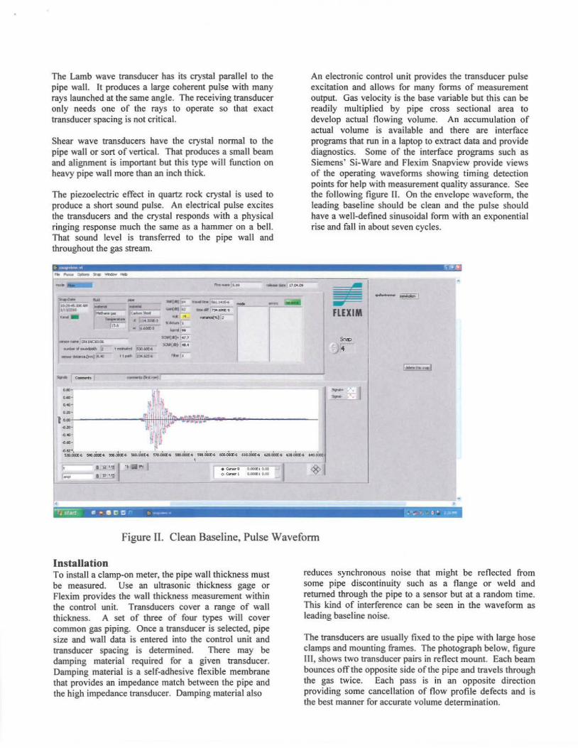
The transducers are usually fixed to the pipe with large hose clamps and mounting frames. The photograph below, figure Ill. shows two transducer pairs in reflect mount. Each beam bounces off the opposite side of the pipe and trave ls through the gas twice. Each pass is in an opposite direction providing some cancellation of flow profile defects and is the best manner for accurate volume detennination.
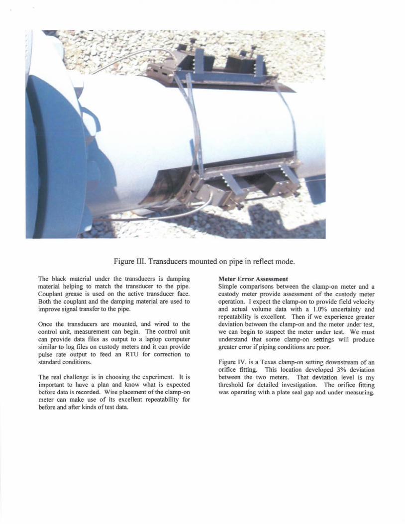
Figure III. Transducers mounted on pipe in reflect mode.
The black material under the transducers is damping material helping to match the transducer to the pipe. Couplant grease is used on the active transducer face. Both the couplant and the damping material are used to improve signal transfer to the pipe.
Once the transducers are mounted, and wired to the control unit, measurement can begin. The control unit can provide data files as output to a laptop computer similar to log files on custody meters and it can provide pulse rate output to feed an RTU for correction to standard conditions.
The real challenge is in choosing the eKperiment. It is important to have a plan and know what is eKpected before data is recorded. Wise pl3cement orthe clamp-on meter can make use of its excellent repeatability for before and after kinds of test data.
Meter Error Assessment Simple comparisons between the c1amp-on meter and a custody meter provide assessment of the custody meter operation. I expect the c1amp-on to provide field velocity and actual volume data with a 1.0% uncertainty and repeatability is excellent. Then if we experience greater deviation between the clamp-on and the meter under test, we can begin to suspect the meter under test. We must understand that some c1amp-on settings will produce greater error if piping conditions are poor.
Figure IV. is a Texas c1amp-on sening downstream ofan orifice fining. This location developed 3% deviation between the two meters. That deviation level is my threshold for detailed investigation. The orifice fitting was operating with. a plate seal gap and under measuring.

A series of meters of various types were investigated and Figure V. illustrates findings. The first meter is a commercial ultrasonic meter with a transducer problem. The second meter bar is a rotary four-inch positive meter. The sixth bar approaching two percent error has installation effects. That pennanent c1amp-on check meter is installed in a straight pipe but there are four elbows out
COMPARISON WITH CLAMP-ON METER
of plane with little separation and a final reducer immediately upstream. Profile distortion was con tinned by the damp-on test meter in a fashion similar to a later section in this paper. The deviation of the blue and fuchsia orifice meter bars of figure V. was related to use of the prior month 's gas composition data.
, r--------------------------------, SWIRL
, -I-----------;~
i !o • !
. , ..j..I-~-~-~----~
1 % Clamp-on uncertainty
~ +-----------------------------------~
Meter Stations
Figure V. Field Comparison Between Clamp--on And Reference Meter.
.:I 16-inch USM
. 4-inctl 6m Rotary
o Permanent Clamp-on 12-irlCh
. Permanent C lamp-on 12-inch
• Permanent Clamp-on 10-inch
.:I Permanent C lamp-on 8-inch
• O rifice 12-inch
o Orifice 1 Q-Inch
• Orifice 6-inctl
• Orifice 8-irlCh
o Orifice &-inch
III O rifice &-inch
• Orifice &-inch
• O rifi ce 6-inch
• Orifice 6_lnch
• Orifice 6-inch
a Orifice 2 -inch
Profile Indicator Beyond simple volume measurement, the unit can detect flow profile defects through rotational analysis. This technique operates the unit in a direct single pass through the pipe and then measurements are taken at multiple positions around the pipe. If the flow is fu lly developed and symmetrical as required for custody transfer, all of the measurements at any position will produce the same flow rate. Profile distortions will show
ROTAll0NAL DATA Twtln-tnc:h Pipe
Row Rate ad"
up as variable flow rate for the different positions around a pipe. Eight positions are recorded and flow rate must be held constant or the data can be nonnalized to average flow rate during the data collection period. The polar plot. figure VI. below shows typical field data for a twelve-inch meter. The clamp-on was mounted near the in let to the ultrasonic meter. This data resulted from a side inlet elbow and short meter run lengths. Measurement error is likely for this profile.
TOP OF PIPE of
7 3
s
Figure VI. Rotational Data Looking upstream.
PLANE o f INLET ELBOW
FLOW FROM THIS SIDE
Leakage Check The clamp-on meter has a true zero. It makes use of the acoustic path through the steel pipe wall compared to the acoustic gas path to find zero flow. The threshold of low velocity detection in the clamp-on is about 0.02 feet-persecond. Above 0.02 feet-per-second, gas is flowing.
It is feasible to hand hold a pair of transducers for leak checking. That is a quick way to sample various positions. If velocity is indicated, a complete installation can be performed to obtain reliable data. Low velocity, even a fraction of a foot -per-second accumulates to significant gas value over time.
One site was found where three closed valves in series were leaking between Companies. The site had been unused for many years and likely was leaking all those years.
Another turbine meter station was found where the small summer load was not enough to cause the turbine meter to tum. The clamp-on meter registered the take and the flow went to zero as soon as the customer became aware that the flow rate was visible.
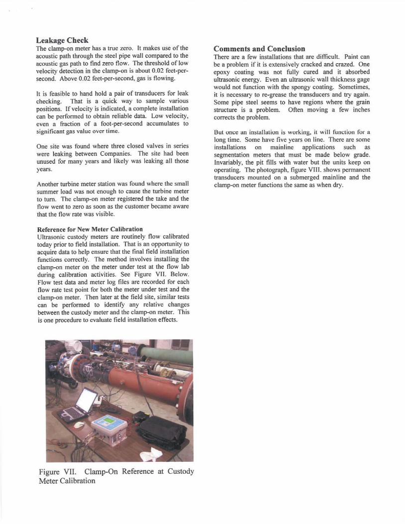
Reference for New Meter Calibration Ultrasonic custody meters are routinely flow calibrated today prior to field installation. That is an opportunity to acquire data to help ensure that the final field installation functions correctly. The method involves installing the clamp-on meter on the meter under test at the flow lab during calibration activities. See Figure VII. Below. Flow test data and meter log files are recorded for each flow rate test point for both the meter under test and the clamp-on meter. Then later at the field site, similar tests can be performed to identify any relative changes between the custody meter and the clamp-on meter. This is one procedure to evaluate fie ld installation effects.
Figure VII. Clamp-On Reference at Custody Meter Calibration
Comments and Conclusion There are a few installations that are difficult. Paint can be a problem if it is extensively cracked and crazed. One epoxy coating was not fully cured and it absorbed ultrasonic energy. Even an ultrasonic wall thickness gage would not function with the spongy coating. Sometimes, it is ne<::essary to re-grease the transducers and try again. Some pipe steel seems to have regions where the grain structure is a problem. Often moving a few inches corrects the problem.
Bul um;t: an inslallation is woril.ing, it will fUllction for a long time. Some have five years on line. There are some installations on mainline applications such as segmentation meters that must be made below grade. Invariably, the pit fills with water but the units keep on operating. The photograph, figure VIII. shows permanent transducers mounted on a submerged mainline and the clamp-on meter functions the same as when dry.
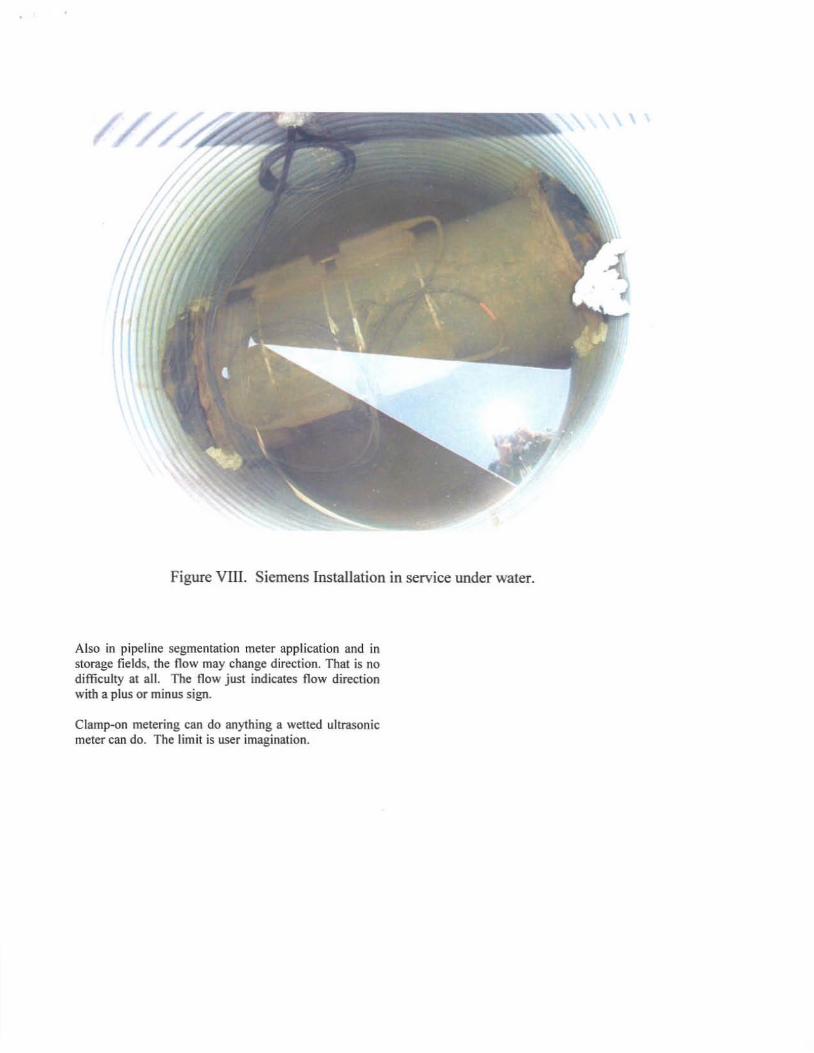
Figure VIII. Siemens Installation in service under water.
Also in pipeline segmentation meter application and in storage fields. the flow may change direction. That is no difficulty at all. The flow j ust ind icates flow direction with a plus or minus sign.
Clamp.on metering can do anything a wened ultrasonic meter can do. The limit is user imagination.

William E. Frasier Jr.
Bill Frasier holds an Electrical Engineering Degree from the University of Nebraska. He has pipeline experience with Northern Natural Gas, Northern Border Pipeline and related companies. He participated in AGA and PRCI and has led industry groups and authored engineering standards and technical papers at industry meetings regarding meteor burst radio, compressor testing, and gas measurement. Prior positions include all aspects of engineering design and supervision, technical service, regulatory management, and measurement specialist. Bill was responsible for design and completion of an early largescale ultrasonic meter pipeline expansion and championed discussion with CEESI for the CLEAR LAKE IOWA CEESI meter calibration facility. For three years, Bill provided consulting services through Liberty Pipeline Services LLC and now is employed by CEESllowa.