claClass II Water Treatment Plant Operator Program Manualss II.pdf
269
Class II Water Treatment Plant Operator Program Manual prepared for: Government of the Northwest Territories Municipal and Community Affairs P.O. Box 1320 Yellowknife, NT X1A 3S9 prepared by: FSC Architects & Engineers 4910 53rd Street P.O. Box 1777 Yellowknife, NT X1A 2P4 FSC Project Number: 2003-0070
-
Upload
hussein-ali-mahdi-al-zubaidy -
Category
Documents
-
view
108 -
download
33
description
Water treatment plant operators have vital roles in ensuring the health and well being ofthe communities in which they service. Some of these services are often taken forgranted.The Class II Water Treatment Plant operator is responsible for one or all of the followingaspects of their communitys water system.• Water delivery and distribution;• Disinfection and filtration;• Administration and sampling.
Transcript of claClass II Water Treatment Plant Operator Program Manualss II.pdf
Class II Water Treatment Plant Operator Program Manual
prepared for:
Government of the Northwest Territories
Municipal and Community Affairs P.O. Box 1320
Yellowknife, NT X1A 3S9
prepared by:
FSC Architects & Engineers 4910 53rd Street P.O. Box 1777
Yellowknife, NT X1A 2P4
FSC Project Number: 2003-0070
CLASS II
11/03/03 II
TABLE OF CONTENTS
1.0 INTRODUCTION.........................................................................1-1
2.0 WATER TREATMENT ................................................................2-1 2.1 SOURCES AND CHARACTERISTICS ..................................................................... 2-1 2.2 PRE-TREATMENT ............................................................................................... 2-3 2.3 COAGULATION & FLOCCULATION..................................................................... 2-5 2.4 SEDIMENTATION.............................................................................................. 2-11 2.5 DISSOLVED AIR FLOATATION.......................................................................... 2-19 2.6 FILTRATION..................................................................................................... 2-19 2.7 MEMBRANE FILTRATION ................................................................................. 2-23 2.8 WATER HARDNESS.......................................................................................... 2-25 2.9 ALKALINITY .................................................................................................... 2-28 2.10 TASTE & ODOUR CONTROL............................................................................. 2-29 2.11 IRON AND MANGANESE CONTROL................................................................... 2-30 2.12 DISINFECTION.................................................................................................. 2-37 2.13 SCALING AND CORROSION CONTROL .............................................................. 2-48 2.14 REVIEW ........................................................................................................... 2-55
3.0 CENTRIFUGAL PUMPS...............................................................3-1 3.1 GENERAL........................................................................................................... 3-1 3.2 OPERATION UNDER SUCTION LIFT CONDITIONS ................................................ 3-2 3.3 TOTAL DYNAMIC HEAD .................................................................................... 3-3 3.4 PUMP CURVES................................................................................................... 3-3 3.5 MULTIPLE PUMP OPERATION ............................................................................ 3-5 3.6 WATER HAMMER .............................................................................................. 3-7 3.7 DESIGN DUTY POINT OF PUMP .......................................................................... 3-8 3.8 VARIABLE SPEED PUMPS................................................................................... 3-8 3.9 REVIEW ............................................................................................................. 3-9
4.0 CONTROL AND INSTRUMENTATION...........................................4-1 4.1 TYPES OF MEASUREMENT ................................................................................. 4-1 4.2 CONTROLLERS................................................................................................... 4-7 4.3 RECORDERS....................................................................................................... 4-7 4.4 TOTALIZERS ...................................................................................................... 4-8 4.5 OPERATION AND MAINTENANCE....................................................................... 4-8 4.6 REVIEW ............................................................................................................. 4-9
5.0 CROSS CONNECTION CONTROL AND BACKFLOW PREVENTION.5-1 5.1 DEFINITION ....................................................................................................... 5-1 5.2 PREVENTION...................................................................................................... 5-1 5.3 OPERATOR RESPONSIBILITIES ........................................................................... 5-4 5.4 REVIEW ............................................................................................................. 5-5
6.0 SAFETY.....................................................................................6-1 6.1 RESPONSIBILITY FOR SAFETY............................................................................ 6-1 6.2 SAFETY PROGRAMS........................................................................................... 6-2 6.3 PLANT SAFETY .................................................................................................. 6-2 6.4 ELECTRICAL SAFETY......................................................................................... 6-3 6.5 INFECTIONS AND INFECTIOUS DISEASES............................................................ 6-4 6.6 HAZARDOUS GASES .......................................................................................... 6-4
CLASS II
11/03/03 III
6.7 CHEMICAL HANDLING....................................................................................... 6-5 6.8 SAFETY EQUIPMENT.......................................................................................... 6-5 6.9 CONFINED SPACE ENTRY .................................................................................. 6-6 6.10 SAFETY ADMINISTRATION RESPONSIBILITIES ................................................... 6-6 6.11 SUMMARY ......................................................................................................... 6-7 6.12 REVIEW ............................................................................................................. 6-9
7.0 EMERGENCY PREPAREDNESS....................................................7-1 7.1 OBJECTIVES....................................................................................................... 7-1 7.2 INTRODUCTION.................................................................................................. 7-1 7.3 NEED FOR EMERGENCY PREPAREDNESS............................................................ 7-1 7.4 ASSESSING THE SYSTEM.................................................................................... 7-2 7.5 PROTECTING THE SYSTEM ................................................................................. 7-5 7.6 CONTINGENCY PLANNING ................................................................................. 7-6 7.7 REVIEW ............................................................................................................. 7-7
8.0 SAMPLING ................................................................................8-1 8.1 INTRODUCTION.................................................................................................. 8-1 8.2 SAMPLING FOR ANALYSIS BY A LABORATORY .................................................. 8-2 8.3 TESTING THE SAMPLE........................................................................................ 8-2 8.4 QUALITY ASSURANCE AND QUALITY CONTROL................................................ 8-3 8.5 REVIEW ............................................................................................................. 8-5
9.0 ADMINISTRATION.....................................................................9-1 9.1 MAINTENANCE MANAGEMENT.......................................................................... 9-1 9.2 RECORDS KEEPING............................................................................................ 9-2 9.3 INVENTORY CONTROL....................................................................................... 9-5 9.4 SUMMARY ......................................................................................................... 9-6 9.5 REVIEW ............................................................................................................. 9-6
CLASS II
11/03/03 IV
LIST OF ADDENDA ADDENDUM A GLOSSARY
ADDENDUM B MATH TOPICS, DOSAGE EXAMPLES, CHEMISTRY AND SOLUTION PREPARATION
ADDENDUM C GUIDELINES FOR CANADIAN DRINKING WATER QUALITY (6TH EDITION)
ADDENDUM D CWMS WATER SUPPLY AND DISTRIBUTION SHEETS
ADDENDUM E ABC NEED-TO-KNOW CRITERIA
ADDENDUM F ADDITIONAL SOURCES OF INFORMATION
ADDENDUM G NWT PUBLIC HEALTH ACT – PUBLIC WATER SUPPLY REGULATIONS
CLASS II INTRODUCTION
11/03/03 1-1
11.0 INTRODUCTION
Water treatment plant operators have vital roles in ensuring the health and well being of the communities in which they service. Some of these services are often taken for granted.
The Class II Water Treatment Plant operator is responsible for one or all of the following aspects of their community�s water system.
• Water delivery and distribution;
• Disinfection and filtration;
• Administration and sampling.
The Class II Operator is another step beyond the responsibilities of the Class I Operator. As such, it is expected that you have already had taken the Class I Operator course and have practiced for two or more years in a Class I plant or plant with a higher rating. If so, it is now time to take the step toward a more theoretical approach to water treatment.
In your Class I course you learned much of the practical aspects of the water treatment system, however, in the Class II course you will learn to diagnose and remedy situations using a more theoretical approach. The Class II course also will expand upon the subjects that have already been addressed. You will learn specifically the details of:
• Coagulation, flocculation, sedimentation and clarification;
• Filtration;
• Centrifugal pumps
• Controls and instrumentation;
• Safety
• Emergency Preparedness
• Sampling;
• Administration.
The above are skills required to operate Class II Water Treatment Plants. Class II plants may use some degree of chemical softening, clarification or iron and manganese removal.
The water treatment plant certification is a voluntary program to further the skills and expertise of community operators throughout the Northwest Territories. Class II Water Treatment Plant certification is currently a voluntary exercise for your own personal benefit, however the GNWT is in the process of making it a mandatory requirement
CLASS II INTRODUCTION
11/03/03 1-2
1through legislation. However, by becoming certified and maintaining your certification you will be better able to perform your work with due diligence.
We recommend that all operators hold a certificate equal to or greater than the facility classification. Certification is intended for all operators, not just those in charge.
Certification of the operators will be based on a combination of formal education, experience, training and examination. Therefore, certification is not entirely based on the contents of this course alone. The experience you bring to this course is vital. Many of your day-to-day decisions are based on your past experience and not the information coming from a manual. You know your own community�s system better than anyone else outside your community.
The ultimate role in the certification of operators across the Northwest Territories is to raise the standard of water treatment in our communities. The information given during the course and written in this manual is based upon the latest standards and practices and will hopefully become another useful tool in your continuing professional development.
Remember, that this manual is only meant as a guide and is never meant to supersede the authority of the Public Drinking Water Supply Regulations under the Public Health Act or your local Environmental Health Officer.
CLASS II CENTRIFUGAL PUMPS
11/03/03 2-1
22.0 WATER TREATMENT
2.1 SOURCES AND CHARACTERISTICS
It is important to know where the water entering a plant comes from as the source often affects the quality of the water, the amount available, and the treatment required.
Groundwater is water that lies below the surface of the ground. Wells are often used to draw groundwater. Some groundwater can be free of turbidity and microorganisms because the water has been naturally filtered as it travelled through the soil. Other groundwater sources can be influenced by surface conditions and porous soils. As a result, the bacteriological and chemical quality of these sources can fluctuate.
Groundwater is often high in mineral content and can contain dissolved gases such as methane and hydrogen sulphide.
Surface water comes from two very different sources: rivers, and lakes. Surface waters in their natural state are potentially unsafe for human consumption because they are constantly exposed to contamination from human, animal, industrial wastes, and from natural sources such as soil, vegetation, and algae.
Rivers can be a difficult source of water to treat as the turbidity can change rapidly and dramatically.
Lakes are less prone to changes in turbidity as suspended matter tends to settle to the bottom, however, ice cover can cause degradation along with taste and odour problems in water quality.
All natural waters contain some turbidity and colour. Turbidity is caused by very finely divided particles held in suspension. This gives the water a cloudy appearance. Colour is caused by dissolved and colloidal particles, a result of organic or inorganic material in the water.
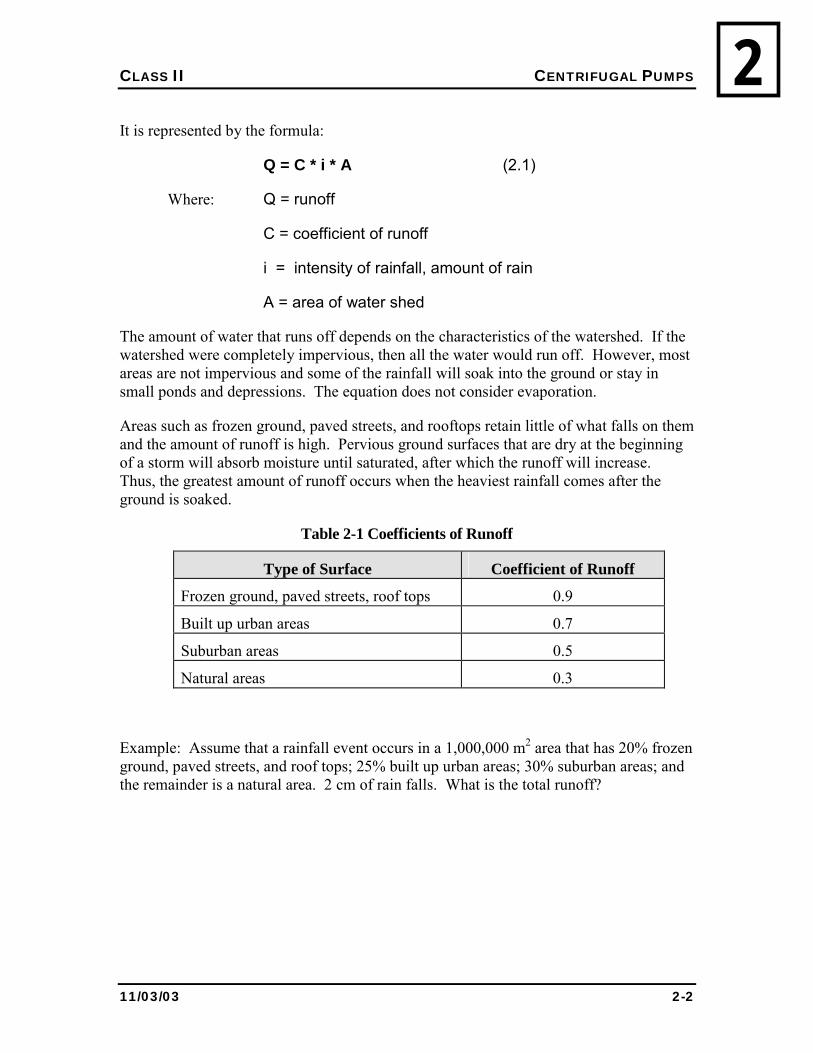
2.1.1 RATIONAL METHOD FOR DETERMINING RUNOFF
The Rational Method is a mathematical way of estimating the amount of water that runs off a watershed during a rainfall event.
CLASS II CENTRIFUGAL PUMPS
11/03/03 2-2
2It is represented by the formula:
Q = C * i * A (2.1)
Where: Q = runoff
C = coefficient of runoff
i = intensity of rainfall, amount of rain
A = area of water shed
The amount of water that runs off depends on the characteristics of the watershed. If the watershed were completely impervious, then all the water would run off. However, most areas are not impervious and some of the rainfall will soak into the ground or stay in small ponds and depressions. The equation does not consider evaporation.
Areas such as frozen ground, paved streets, and rooftops retain little of what falls on them and the amount of runoff is high. Pervious ground surfaces that are dry at the beginning of a storm will absorb moisture until saturated, after which the runoff will increase. Thus, the greatest amount of runoff occurs when the heaviest rainfall comes after the ground is soaked.
Table 2-1 Coefficients of Runoff
Type of Surface Coefficient of Runoff
Frozen ground, paved streets, roof tops 0.9
Built up urban areas 0.7
Suburban areas 0.5
Natural areas 0.3
Example: Assume that a rainfall event occurs in a 1,000,000 m2 area that has 20% frozen ground, paved streets, and roof tops; 25% built up urban areas; 30% suburban areas; and the remainder is a natural area. 2 cm of rain falls. What is the total runoff?
CLASS II CENTRIFUGAL PUMPS
11/03/03 2-3
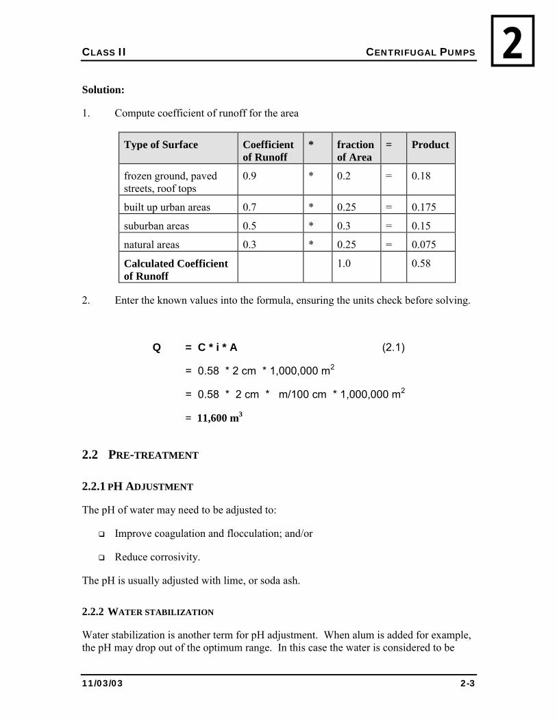
2Solution:
1. Compute coefficient of runoff for the area
Type of Surface Coefficient of Runoff
* fraction of Area
= Product
frozen ground, paved streets, roof tops
0.9 * 0.2 = 0.18
built up urban areas 0.7 * 0.25 = 0.175
suburban areas 0.5 * 0.3 = 0.15
natural areas 0.3 * 0.25 = 0.075
Calculated Coefficient of Runoff
1.0 0.58
2. Enter the known values into the formula, ensuring the units check before solving.
Q = C * i * A (2.1)
= 0.58 * 2 cm * 1,000,000 m2
= 0.58 * 2 cm * m/100 cm * 1,000,000 m2
= 11,600 m3
2.2 PRE-TREATMENT
2.2.1 PH ADJUSTMENT
The pH of water may need to be adjusted to:
! Improve coagulation and flocculation; and/or
! Reduce corrosivity.
The pH is usually adjusted with lime, or soda ash.
2.2.2 WATER STABILIZATION
Water stabilization is another term for pH adjustment. When alum is added for example, the pH may drop out of the optimum range. In this case the water is considered to be
CLASS II CENTRIFUGAL PUMPS
11/03/03 2-4
2unstable. Lime or soda ash is added to increase the alkalinity of the water and thus, its �stability�.
2.2.3 HYDROGEN SULPHIDE REMOVAL
Hydrogen sulphide (H2S) s not a constituent of surface water and is only found in ground water that has not been exposed to the atmosphere. Where H2S is a problem, it can be removed by:
! Aeration; or
! Oxidation with chlorine, permanganate, or another oxidizing agent.
2.2.4 PRE-SEDIMENTATION
Pre-sedimentation is a step that is often required before coagulation and flocculation in order to remove large particles from the raw water stream. These larger particles can reduce the efficiency of the coagulation and flocculation process.
Settling of larger-sized particles occurs naturally when surface water is stored for a sufficient period of time in a reservoir or a natural lake. Gravitational forces acting in the lake accomplish the same purpose as sedimentation in the water treatment plants; larger particles such as sand and heavy silts settle to the bottom.
Debris dams, grit basins or sand traps can also be used to remove some of the heavier particles from source water. The facilities may be located upstream from the reservoir, treatment plant intake or diversion facilities, and serve to protect the municipal intake pipeline from siltation.
Grit basins may be located between the intake structure and the coagulation flocculation facilities. Thus, pre-sedimentation facilities such as debris dams, impoundments and grit basins reduce the solids removal load at the water treatment plant. At the same time, they provide an equalizing basin, which evens out fluctuations in the concentration of suspended solids in the source water. Water with more suspended solids is mixed with water with less suspended solids.
Pre-sedimentation facilities are often installed in locations where the source water supply is diverted directly from rivers or streams, which can be contaminated, by overland runoff and point source waste discharges.
Ideally, surface waters should be stored in a reservoir and transported directly to the water treatment plant in a pipeline. In a reservoir the heavier solids can settle out before they reach the plant. However, geographical, physical and economic considerations often make this alternative impractical.
CLASS II CENTRIFUGAL PUMPS
11/03/03 2-5
22.3 COAGULATION & FLOCCULATION
Coagulation and flocculation are two of several steps to purify raw water to acceptable standards.
2.3.1 COAGULATION
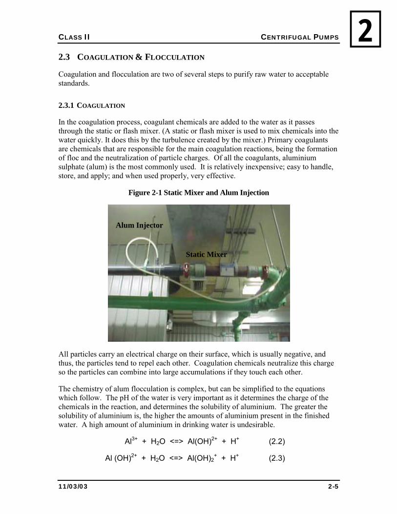
In the coagulation process, coagulant chemicals are added to the water as it passes through the static or flash mixer. (A static or flash mixer is used to mix chemicals into the water quickly. It does this by the turbulence created by the mixer.) Primary coagulants are chemicals that are responsible for the main coagulation reactions, being the formation of floc and the neutralization of particle charges. Of all the coagulants, aluminium sulphate (alum) is the most commonly used. It is relatively inexpensive; easy to handle, store, and apply; and when used properly, very effective.
Figure 2-1 Static Mixer and Alum Injection
All particles carry an electrical charge on their surface, which is usually negative, and thus, the particles tend to repel each other. Coagulation chemicals neutralize this charge so the particles can combine into large accumulations if they touch each other.
The chemistry of alum flocculation is complex, but can be simplified to the equations which follow. The pH of the water is very important as it determines the charge of the chemicals in the reaction, and determines the solubility of aluminium. The greater the solubility of aluminium is, the higher the amounts of aluminium present in the finished water. A high amount of aluminium in drinking water is undesirable.
Al3+ + H2O <=> Al(OH)2+ + H+ (2.2)
Al (OH)2+ + H2O <=> Al(OH)2+ + H+ (2.3)
Alum Injector
Static Mixer
CLASS II CENTRIFUGAL PUMPS
11/03/03 2-6
2 Al(OH)2
+ + H2O <=> Al(OH)3 ↓ + H+ (2.4)
Al(OH)3 + H2O <=> Al(OH)4- + H+ (2.5)
These equations are written in �chemical shorthand� and show the progressive reaction of the aluminium ion to produce a molecule with a negative charge. An important reaction is 2.4, which yields aluminium hydroxide, which forms as a precipitate, denoted by ↓ and is the aluminium floc that is seen.
Note how in each of the reactions a H+ ion is formed. Recall that pH is a measure of the hydrogen ion concentration. If the water has a high alkalinity it will tend to resist pH changes when hydrogen ions are added or removed. The effect on pH of adding aluminium will depend on the properties of the water, but alum will always decrease the pH, the alkalinity, or both.
With most waters the best pH for coagulation and flocculation is treatment plant specific though it is generally between 5 and 7. In the NWT, the natural alkalinity in the water may not be enough to support typical alum dosages without affecting pH. Spring freshet and associated high turbidity may cause a further demand on alkalinity as alum doses increase. Alkalinity needs to be assessed throughout the year and varying conditions, and appropriate adjustments made to keep pH in the optimum range for both flocculation and corrosion control.
Residual aluminium in finished waters has become a great concern. Residual aluminium comes from two sources: floc carryover and soluble aluminium. High soluble concentrations result when the pH is less than 6.0. In order to minimize the amount of soluble aluminium the pH should be maintained in the range of 6.0 to 6.8. Floc carryover can be reduced through the use of coagulant aids, sedimentation and filtration.
Coagulant aids (also called flocculant aids) are used to increase the density of slow settling floc particles, or to strengthen them so they do not break up during settling and filtration.
Polymers are a popular coagulant aid. There are many different polymers on the market classified into three groups:
1. Cationic -- having a negative charge
2. Anionic -- having a positive charge
3. Non-ionic -- having no charge
CLASS II CENTRIFUGAL PUMPS
11/03/03 2-7
2
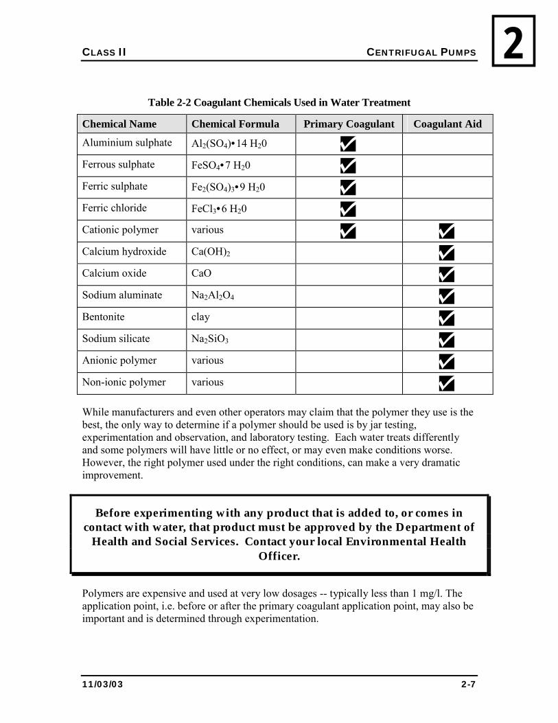
Table 2-2 Coagulant Chemicals Used in Water Treatment
Chemical Name Chemical Formula Primary Coagulant Coagulant Aid
Aluminium sulphate Al2(SO4)•14 H20
Ferrous sulphate FeSO4•7 H20
Ferric sulphate Fe2(SO4)3•9 H20
Ferric chloride FeCl3•6 H20
Cationic polymer various Calcium hydroxide Ca(OH)2 Calcium oxide CaO Sodium aluminate Na2Al2O4 Bentonite clay Sodium silicate Na2SiO3 Anionic polymer various Non-ionic polymer various
While manufacturers and even other operators may claim that the polymer they use is the best, the only way to determine if a polymer should be used is by jar testing, experimentation and observation, and laboratory testing. Each water treats differently and some polymers will have little or no effect, or may even make conditions worse. However, the right polymer used under the right conditions, can make a very dramatic improvement.
Before experimenting with any product that is added to, or comes in contact with water, that product must be approved by the Department of
Health and Social Services. Contact your local Environmental Health Officer.
Polymers are expensive and used at very low dosages -- typically less than 1 mg/l. The application point, i.e. before or after the primary coagulant application point, may also be important and is determined through experimentation.
CLASS II CENTRIFUGAL PUMPS
11/03/03 2-8
2The way in which a polymer works is complex. Interaction of electrical charges on the polymer molecules and on the turbidity particles may be one important factor. The binding or bridging effect of the long polymer molecules may be another factor. But for simplicity, the mechanism is not really important -- either a polymer works for you or it doesn�t.
Most NWT plants use alum and a polymer.
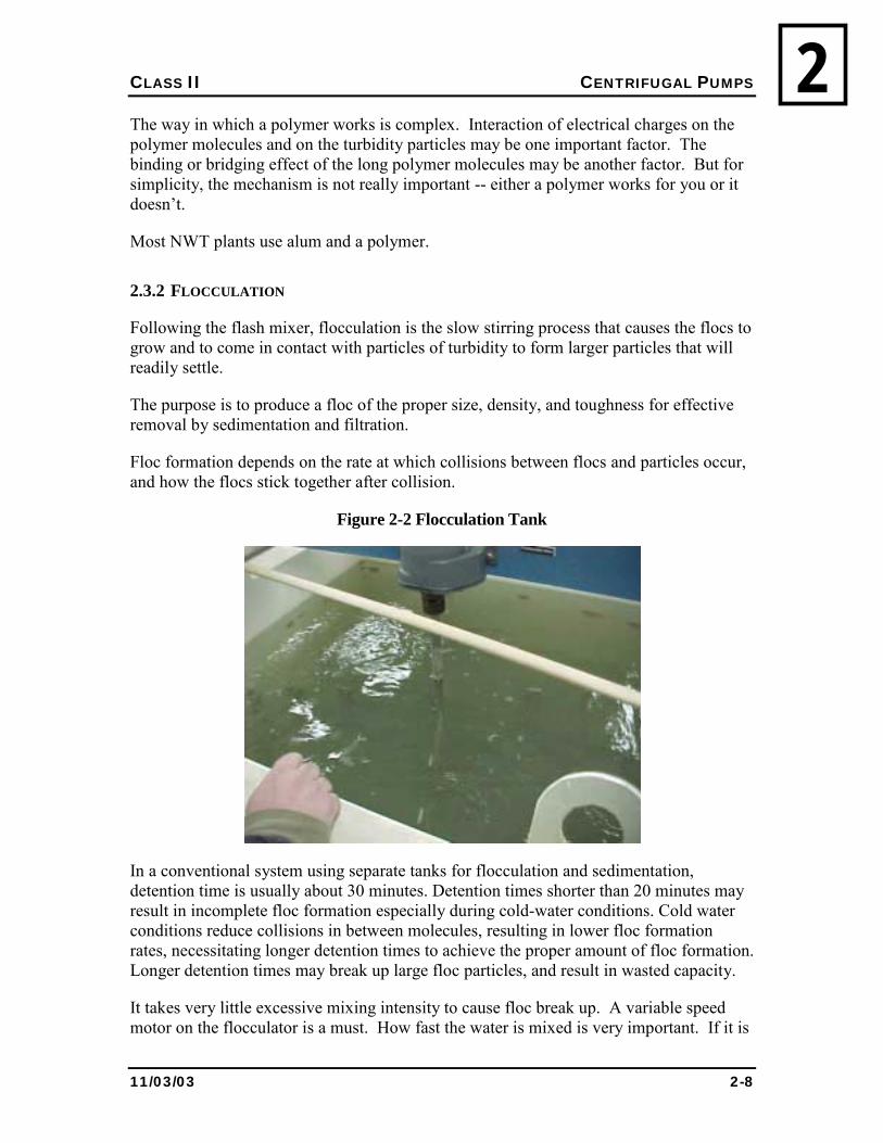
2.3.2 FLOCCULATION
Following the flash mixer, flocculation is the slow stirring process that causes the flocs to grow and to come in contact with particles of turbidity to form larger particles that will readily settle.
The purpose is to produce a floc of the proper size, density, and toughness for effective removal by sedimentation and filtration.
Floc formation depends on the rate at which collisions between flocs and particles occur, and how the flocs stick together after collision.
Figure 2-2 Flocculation Tank
In a conventional system using separate tanks for flocculation and sedimentation, detention time is usually about 30 minutes. Detention times shorter than 20 minutes may result in incomplete floc formation especially during cold-water conditions. Cold water conditions reduce collisions in between molecules, resulting in lower floc formation rates, necessitating longer detention times to achieve the proper amount of floc formation. Longer detention times may break up large floc particles, and result in wasted capacity.
It takes very little excessive mixing intensity to cause floc break up. A variable speed motor on the flocculator is a must. How fast the water is mixed is very important. If it is
CLASS II CENTRIFUGAL PUMPS
11/03/03 2-9
2too slow, there will be relatively few collisions between particles; if it is too fast the flocs could be broken up. Flocs are very delicate. Floc break up is a real problem in many plants and can go unnoticed. There is an easy demonstration.
Take a sample of effluent from the flocculator in a large container such as a pail by letting the water flow gently into the pail. Stir the contents gently and dip a sample from the pail into a 1-litre flask. Take another sample in the same manner into a stoppered bottle. Shake the bottle vigorously for a few seconds and pour the contents into a second 1-litre flask. Observe the contents of each for about an hour. The second flask should have much smaller flocs that settle poorly, and leave a turbid supernatant.
Unfortunately, there are no simple tests to see if the coagulation/flocculation process is working well and it is impossible to provide guidelines or instructions. Experience, careful observation, proper records, and good judgement are the only ways to determine the best operating conditions.
2.3.3 ALUMINIUM RESIDUALS
You are adding aluminium to your process. Therefore, it is important to undertake routine unit process analysis to ensure that chemicals such as aluminium are not carried over in the finished water.
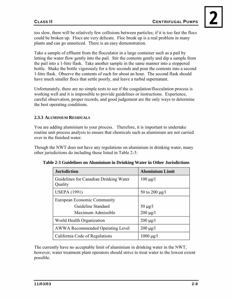
Though the NWT does not have any regulations on aluminium in drinking water, many other jurisdictions do including those listed in Table 2-3:
Table 2-3 Guidelines on Aluminium in Drinking Water in Other Jurisdictions
Jurisdiction Aluminium Limit
Guidelines for Canadian Drinking Water Quality
100 µg/l
USEPA (1991) 50 to 200 µg/l
European Economic Community Guideline Standard Maximum Admissible
50 µg/l 200 µg/l
World Health Organization 200 µg/l
AWWA Recommended Operating Level 200 µg/l
California Code of Regulations 1000 µg/l
The currently have no acceptable limit of aluminium in drinking water in the NWT, however, water treatment plant operators should strive to treat water to the lowest extent possible.
CLASS II CENTRIFUGAL PUMPS
11/03/03 2-10
2As a best practice, residual aluminium concentrations should be maintained below 0.1 mg/l (100 µg/) whenever possible. All conventional treatment plants should be able to approach this value. If aluminium residuals exceed 0.3 mg/l, plant operations should be assessed.
It is your job as operator to ensure that the amount of chemicals (from all sources) is minimized in drinking water.
2.3.4 OPERATIONAL PROBLEMS
The most common operational problem is a sudden change in raw water quality, usually a result of changing turbidity. The causes are many. In the North, some of the most common causes are:
• Spring break up on rivers and lakes;
• Heavy rainstorms;
• High wind;
• Turnover in lakes and reservoirs; and
• Algae blooms or insect hatches.
A significant change in raw water quality means that adjustments may be needed including:
• Changing coagulants;
• Adjusting coagulant dosages;
• Adjusting flash mixer and/or flocculator mixing intensity (speed);
• Adding a coagulant aid; and
• Adjusting alkalinity or pH.
In cases where such a change in raw water quality occurs, jar tests may only provide some of the answers. Final adjustments should be based on careful plant observations and measurements.
Accurate records are essential in preparing for, and responding to, raw water quality changes. Often, events occur at similar times and with similar intensity. Records should include what worked and how well, and what didn�t work so mistakes are not repeated.
CLASS II CENTRIFUGAL PUMPS
11/03/03 2-11
22.4 SEDIMENTATION
2.4.1 DEFINITION
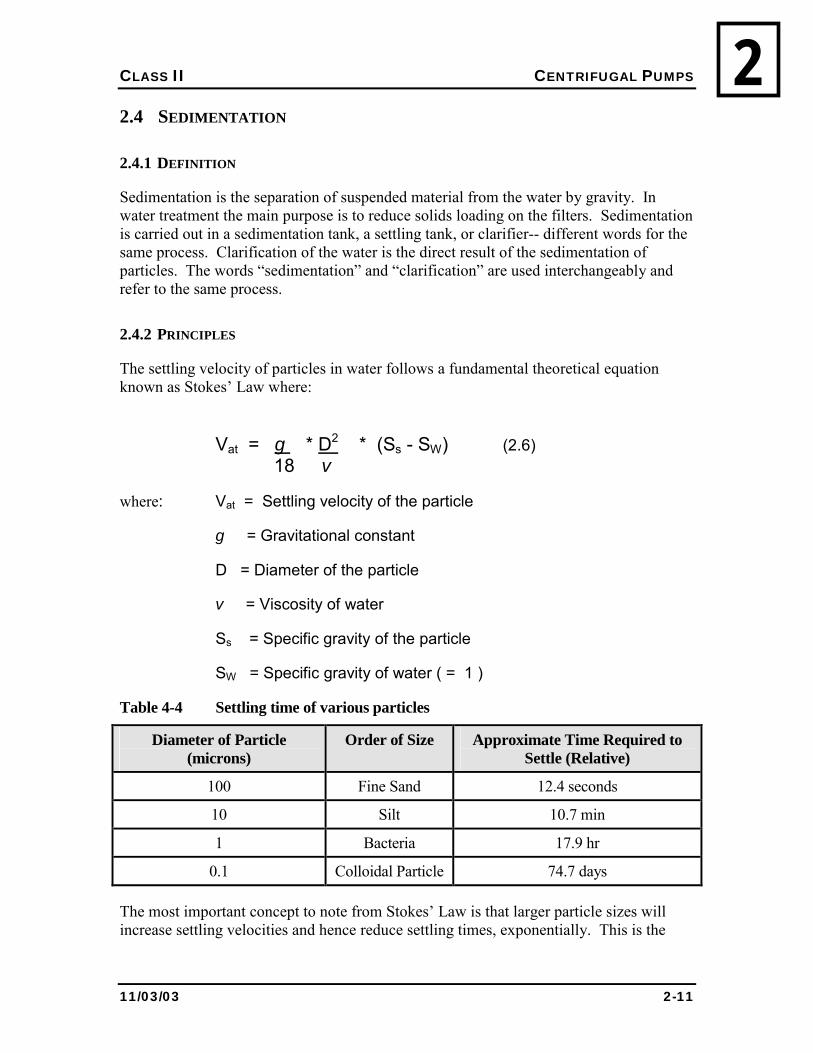
Sedimentation is the separation of suspended material from the water by gravity. In water treatment the main purpose is to reduce solids loading on the filters. Sedimentation is carried out in a sedimentation tank, a settling tank, or clarifier-- different words for the same process. Clarification of the water is the direct result of the sedimentation of particles. The words �sedimentation� and �clarification� are used interchangeably and refer to the same process.
2.4.2 PRINCIPLES
The settling velocity of particles in water follows a fundamental theoretical equation known as Stokes� Law where:
Vat = g * D2 * (Ss - SW) (2.6) 18 v
where: Vat = Settling velocity of the particle
g = Gravitational constant
D = Diameter of the particle
v = Viscosity of water
Ss = Specific gravity of the particle
SW = Specific gravity of water ( = 1 )
Table 4-4 Settling time of various particles
Diameter of Particle (microns)
Order of Size Approximate Time Required to Settle (Relative)
100 Fine Sand 12.4 seconds
10 Silt 10.7 min
1 Bacteria 17.9 hr
0.1 Colloidal Particle 74.7 days
The most important concept to note from Stokes� Law is that larger particle sizes will increase settling velocities and hence reduce settling times, exponentially. This is the
CLASS II CENTRIFUGAL PUMPS
11/03/03 2-12
2rational for having the coagulation/flocculation process. The coagulation/flocculation process increases the size of the particles to reduce to amount of time to settle the particles during sedimentation.
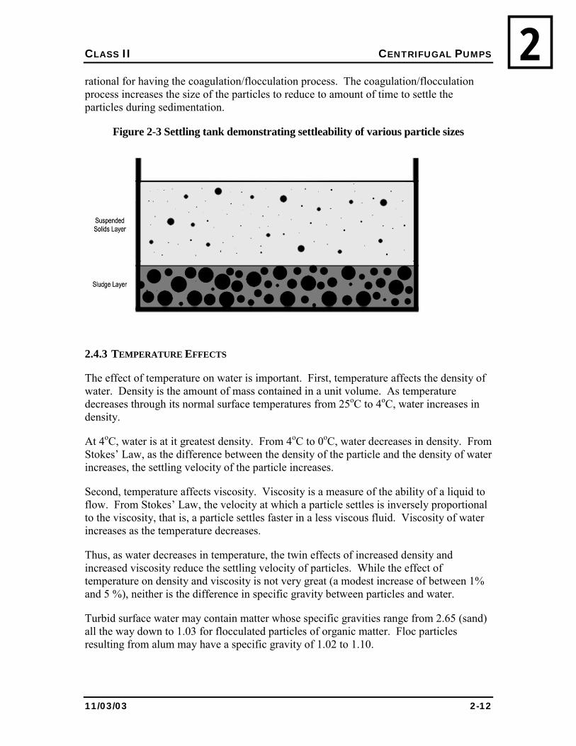
Figure 2-3 Settling tank demonstrating settleability of various particle sizes
2.4.3 TEMPERATURE EFFECTS
The effect of temperature on water is important. First, temperature affects the density of water. Density is the amount of mass contained in a unit volume. As temperature decreases through its normal surface temperatures from 25oC to 4oC, water increases in density.
At 4oC, water is at it greatest density. From 4oC to 0oC, water decreases in density. From Stokes� Law, as the difference between the density of the particle and the density of water increases, the settling velocity of the particle increases.
Second, temperature affects viscosity. Viscosity is a measure of the ability of a liquid to flow. From Stokes� Law, the velocity at which a particle settles is inversely proportional to the viscosity, that is, a particle settles faster in a less viscous fluid. Viscosity of water increases as the temperature decreases.
Thus, as water decreases in temperature, the twin effects of increased density and increased viscosity reduce the settling velocity of particles. While the effect of temperature on density and viscosity is not very great (a modest increase of between 1% and 5 %), neither is the difference in specific gravity between particles and water.
Turbid surface water may contain matter whose specific gravities range from 2.65 (sand) all the way down to 1.03 for flocculated particles of organic matter. Floc particles resulting from alum may have a specific gravity of 1.02 to 1.10.
CLASS II CENTRIFUGAL PUMPS
11/03/03 2-13
2Therefore, cold water will have a noticeable effect on the settleability of particles. Add to this the effects of turbulence, flow currents, edge effects, and sludge build up in a settling tank; the potential for floc carryover increases greatly.
In general, clarification may be classified as four types based on the concentration of particles and their ability to interact. Type 1 Clarification occurs in a dilute suspension when discrete particles that resist
flocculation settle individually and exhibit no interactions. An example of Type 1 clarification is the pre-sedimentation of sand.
Type II Clarification involves the removal of a dilute suspension of particles that are known to flocculate during settling. An example of Type II clarification is the settling of chemically flocculated waters in which particles continue to increase in size as they interact and settle at a faster velocity.
Type III Clarification usually refers to hindered or zone settling and occurs when sludge concentrations at about 500 mg/l. Inter-particle electromagnetic forces hinder the settling of neighbouring particles forming a mass that settles as a blanket. This inter-particle electromagnetic force is the result of similarly charged particles repelling each other. A distinct interface is evident between the settling sludge and the supernatant. An example of Type III clarification would occur in concentrated suspensions of flocculated material at an intermediate depth in a clarifier.
Type IV Clarification occurs at the bottom of a sedimentation basin where settling occurs by the slow compression of the settled sludge. This process is also known as �compression settling�.
2.4.4 DETENTION TIME
Detention time is the theoretical average length of time the water is in the clarifier. Detention time depends on two things: the volume of the clarifier, and the flow rate of the water. It is calculated using the following formula:
Detention time = Volume of Clarifier (2.7) Flow
Most clarifiers have detention times of 1 to 3 hours.
2.4.5 RISE RATE
The rise rate is a measure of the upward velocity of water in the clarifier and is one of the major factors in determining the efficiency of a clarifier. It is also known as the surface loading rate, the surface settling rate, or the overflow rate. Rise rate is defined as the flow per unit surface area of the clarifier:
CLASS II CENTRIFUGAL PUMPS
11/03/03 2-14
2 Rise Rate = Flow (2.8) Surface Area
Although the calculation is normally reported as m3/d per m2, it can be simplified to metres per day; a velocity.
Most clarifiers are designed with rise rates in the range of 25 to 75 m3/d per m2. The lower rise rates are associated with small plants in cold climates.
2.4.6 WEIR LOADING RATE
Water leaves the clarifier by flowing over a weir into some arrangement such as an effluent trough. The length of the weir in relation to the flow over it is important. Too high a weir-loading rate will cause hydraulic gradients in the clarifier, break up floc particles and cause solids to be re-suspended and carried over the weir.
Weir Loading Rate = Flow (2.9) Length of Weir
Most clarifiers have weir loading rates of between 125 and 250 m3/d per m.
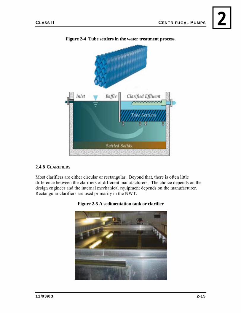
2.4.7 TUBE SETTLERS
Tube settlers, also known as high rate settlers, were developed to increase the efficiency of solids removal in clarifiers. Tube settlers are often found in package systems, which are notorious for poor clarification. Tube settlers often allow increased surface loading rates, often as much as double the conventional loading rate (ie. the amount of solids it can remove in a certain amount of time).
Shown in Figure 2.4, tube settlers generally consist of bundles of plastic tubes about 50 mm square and 500 to 750 mm long. The tubes are placed just below the surface of the clarifier at an angle of 60o to the horizontal. The tube shown in Figure 2.4 is just an example of one type of tube settler, as the tube configuration is generally manufacturer specific.
As the water rises upward through the tube settler, particles tend to impact with the tube wall, stopping their ascent. Their upward velocity now zero, the particles can begin settling unless they become re-suspended by the upward motion.
CLASS II CENTRIFUGAL PUMPS
11/03/03 2-15
2Figure 2-4 Tube settlers in the water treatment process.
2.4.8 CLARIFIERS
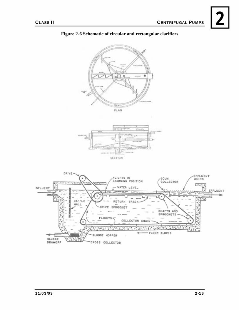
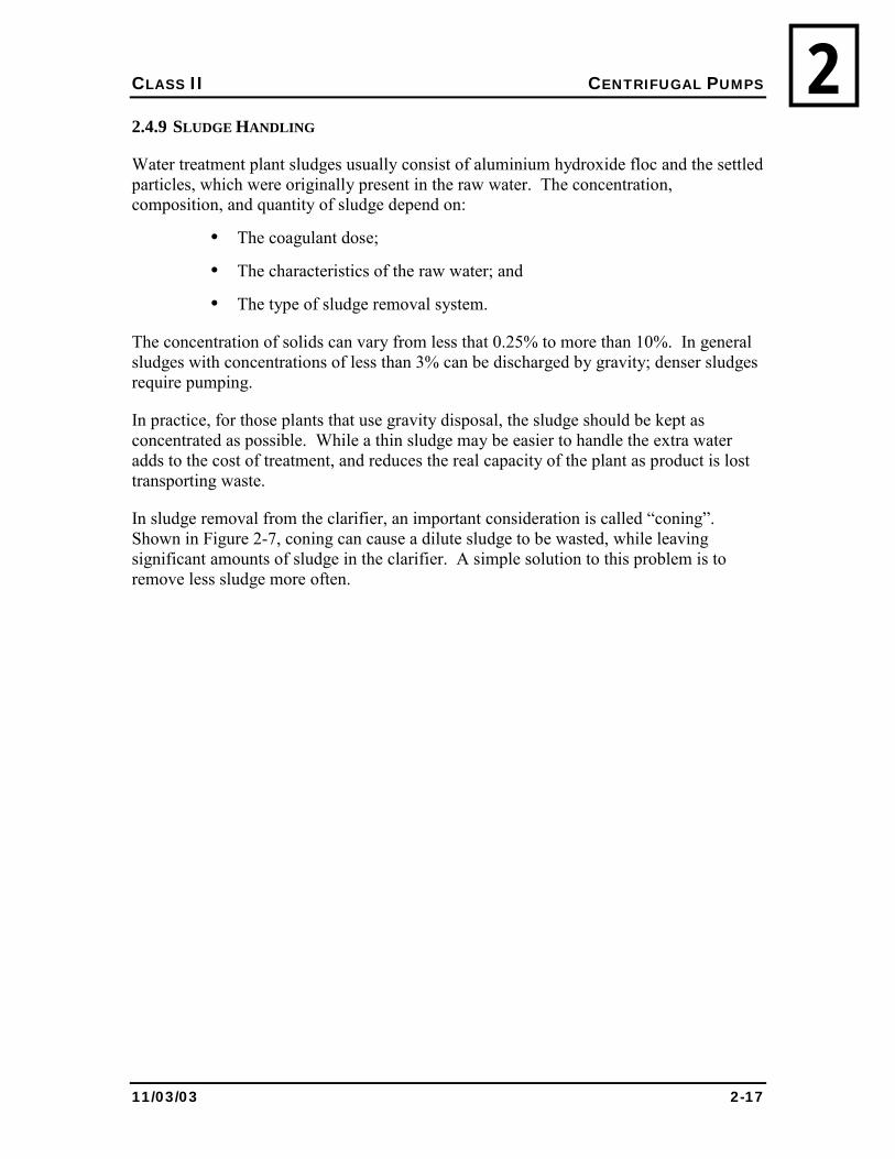
Most clarifiers are either circular or rectangular. Beyond that, there is often little difference between the clarifiers of different manufacturers. The choice depends on the design engineer and the internal mechanical equipment depends on the manufacturer. Rectangular clarifiers are used primarily in the NWT.
Figure 2-5 A sedimentation tank or clarifier
CLASS II CENTRIFUGAL PUMPS
11/03/03 2-16
2Figure 2-6 Schematic of circular and rectangular clarifiers
CLASS II CENTRIFUGAL PUMPS
11/03/03 2-17
22.4.9 SLUDGE HANDLING
Water treatment plant sludges usually consist of aluminium hydroxide floc and the settled particles, which were originally present in the raw water. The concentration, composition, and quantity of sludge depend on:
• The coagulant dose;
• The characteristics of the raw water; and
• The type of sludge removal system.
The concentration of solids can vary from less that 0.25% to more than 10%. In general sludges with concentrations of less than 3% can be discharged by gravity; denser sludges require pumping.
In practice, for those plants that use gravity disposal, the sludge should be kept as concentrated as possible. While a thin sludge may be easier to handle the extra water adds to the cost of treatment, and reduces the real capacity of the plant as product is lost transporting waste.
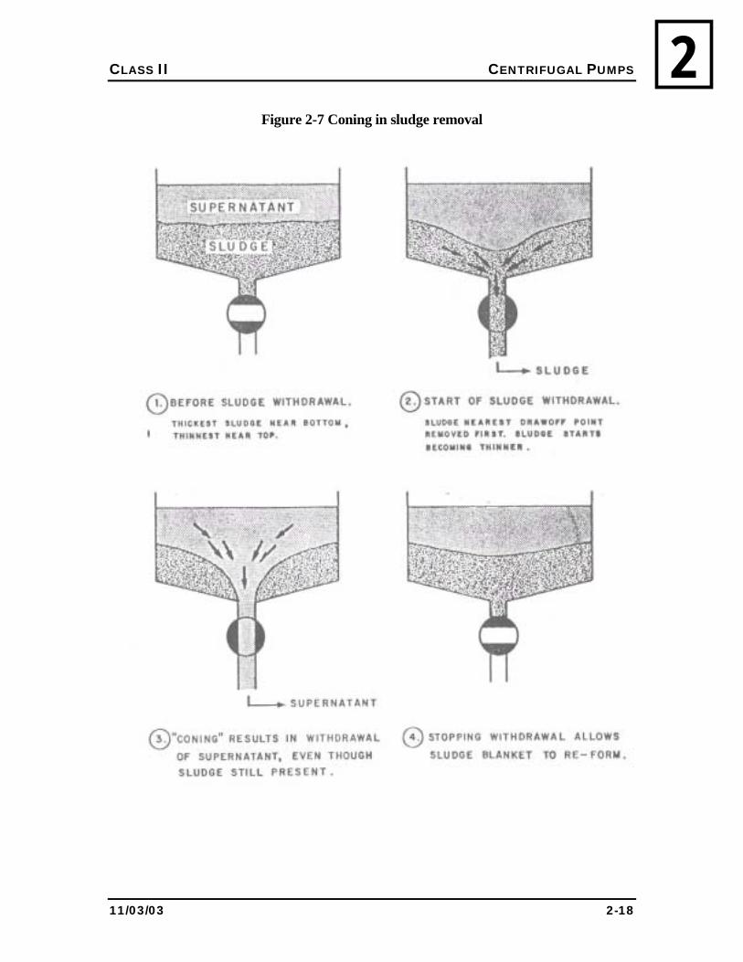
In sludge removal from the clarifier, an important consideration is called �coning�. Shown in Figure 2-7, coning can cause a dilute sludge to be wasted, while leaving significant amounts of sludge in the clarifier. A simple solution to this problem is to remove less sludge more often.
CLASS II CENTRIFUGAL PUMPS
11/03/03 2-18
2Figure 2-7 Coning in sludge removal
CLASS II CENTRIFUGAL PUMPS
11/03/03 2-19
22.4.10 SLUDGE DISPOSAL
Alum sludges have been researched to determine the most suitable method for their disposal. In piped communities most gravity discharged alum sludges are discharged directly to the sewer to be dealt with at the sewage treatment facility.
In trucked communities, three methods for disposal are available:
• Direct discharge to the sewage treatment facility;
• Co-disposal in the modified landfill; or
• Landfilling in a mono-fill facility.
Choice of any one of these alternatives depends on the cost of operation, the leachability of the alum sludge, and the approval of the regulatory authority.
2.5 DISSOLVED AIR FLOATATION
Dissolved air floatation (DAF) is an adaptation of sedimentation by understanding the principles of Stokes� Law.
Shown in Figure 2.7, fine bubbles attach to the particles causing them to float to the surface where they are removed by mechanical scraping or by the less commonly used method of flooding. Mechanical scraping can produce sludges with concentrations of 1% to 3%, while flooding produces sludges with concentrations less than 0.2%.
The process is a substitute for sedimentation and is used primarily to treat water, which are difficult to treat with a conventional system. These include: large quantities of algae; or highly coloured, low temperature waters. In addition, floatation processes are capable of removing smaller particles (>10 µm) than sedimentation processes (>100 µm).
Detention times for the process are short, 10 to 20 minutes, as the floc will start to break up after 30 minutes or so.
The process has been used in the mining industry for many years to concentrate ores such as gold, lead/zinc, and copper.
2.6 FILTRATION
The process of filtration was thoroughly discussed in the Class I Water Treatment Plant Operations training manual. For NWT Class II operators, some of the principles and theory of operation will be discussed.
CLASS II CENTRIFUGAL PUMPS
11/03/03 2-20
2Figure 2-8 The dissolved air floatation process
2.6.1 FILTER LOADING RATE
Filter Loading Rate = Flow (2.10) Surface Area
Design loading rates for a particular filter will be specified by the manufacturer. Most dual media rapid gravity filters operate between 5 and 10 m3/h per m2. Higher loading rates can be used but at the expense of: shorter runs; higher head losses; and increased effluent turbidity.
2.6.2 HEAD LOSS
Water is forced through the filters by pressure, or head, that is the water above the filter bed.
The head loss produced by a given flow on any filter can be described by the following;
hf = f�L(1-e)V2 (2.11) e3gd
CLASS II CENTRIFUGAL PUMPS
11/03/03 2-21
2where: hf = head loss
f� = friction factor based on the amount of drag around the media
L = depth of the bed
e = porosity of the bed
V = filter loading rate
g = gravitational constant
d = diameter of the media grains
Other factors, which affect head loss, include:
• The type of underdrain system;
• Clogging of the underdrain system; and
• The degree of media clogging.
A clean filter will normally have a very low head loss. If the media is not backwashed properly, or the underdrains become clogged, the initial head loss of a just backwashed filter bed will increase. This is important data to record so that you will know how the filter and your backwashing procedure are functioning over time.
The general concept for the operator to understand is that the smaller the filters pores are the more head loss that will be created. Higher head losses result in increased pump pressure requirements.
2.6.3 ORGANIC GROWTHS
In the past, municipalities often used to pre-chlorinate water to prevent bacterial and algal growths in the filter beds. Nowadays, to reduce the development of chlorination by-products such as trihalomethanes (THMs), caused by reaction of chlorine with organic material, municipalities chlorinate afterwards. This post-chlorination process begins with the filter effluent. Bacterial and algal growths in the filter now again become a concern.
When such growths become a concern, disinfection of the raw water could be accomplished using either potassium permanganate, or ozone. Both these options are more expensive than chlorine, but will not produce THMs.
When the raw water contains a low organic content, an alternate strategy would be to lightly dose the raw water with chlorine to minimize bacterial and algal growths, and then follow up with post-chlorination to ensure that your product is properly disinfected.
CLASS II CENTRIFUGAL PUMPS
11/03/03 2-22
2In either case, the assistance of process control specialists should be enlisted to ensure that you meet the three goals of taste and odour control, reduction of disinfection by-products, and proper disinfection.
2.6.4 BACKWASHING
There are three criteria used to determine when a filter needs to be backwashed:
• Filter effluent turbidity;
• High head loss indicating media clogging; and
• Length of run.
Filter effluent turbidity usually increases as the length of filter run increases. At some point, the filter effluent turbidity will become unacceptable. The Maximum Acceptable Concentration in the Guidelines for Canadian Drinking Water Quality is 1 NTU, but many operators strive to achieve a lower number. The current guideline is under review and may change some time in the near future. Contact your regional MACA representative for the latest edition of the guidelines.
Media clogging is indicated by the head loss through the beds. Once the head loss reaches a pre-determined value, the beds are assumed to be clogged.
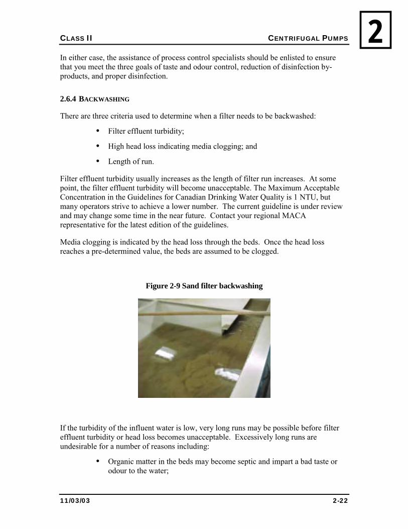
Figure 2-9 Sand filter backwashing
If the turbidity of the influent water is low, very long runs may be possible before filter effluent turbidity or head loss becomes unacceptable. Excessively long runs are undesirable for a number of reasons including:
• Organic matter in the beds may become septic and impart a bad taste or odour to the water;
CLASS II CENTRIFUGAL PUMPS
11/03/03 2-23
2• Particulate matter may pack in the bed and stick to the media grains
making backwashing difficult and/or causing channelling in the filter;
• Special filters such as those used for iron and manganese removal may become packed and channelled, thus, reducing their ability to function.
2.6.5 DISPOSAL OF BACKWASH WASTES
Backwash wastewater usually contains low concentrations (less than 1%) of solids consisting mainly of alum floc and fine turbidity particles. They are normally disposed in two ways: recycled to the raw water inlet; or discharged to sewage.
When recycled to the raw water inlet, the particles once again undergo flocculation, coagulation, and sedimentation. The problem with this scheme is that while many particles are removed before entering the filter, many more than originally passed through the process will pass through again. This continuing recycle will cause an increasing build-up of fine particles in the water being treated. This results in shorter filter runs and increased treated water turbidity.
Discharge to sewage is a common practice.
2.7 MEMBRANE FILTRATION
Membrane filtration is a relatively new water technology with respect to municipal water treatment. Membrane filtration can replace the clarification, coagulation and flocculation steps of the water treatment process. Also, depending on the pore size of membrane, filtration can replace the initial disinfection step as well. Note that chlorination will always be required in order to maintain disinfection beyond the water treatment plant.
Membrane filters typically consist of series of hollow polymer tubes inserted into the water. A vacuum process sucks the water through the pores on the sides of tubes, removing the particles larger than the pore size. The filtered water usually proceeds to the disinfection step, while the dirty water containing the filtered solids is back-flushed from the system. This is a typical membrane process; however, the process depends on the type and manufacturer of the membranes used. There are four varieties of membrane filter as shown in Figure 2.10.
CLASS II CENTRIFUGAL PUMPS
11/03/03 2-24
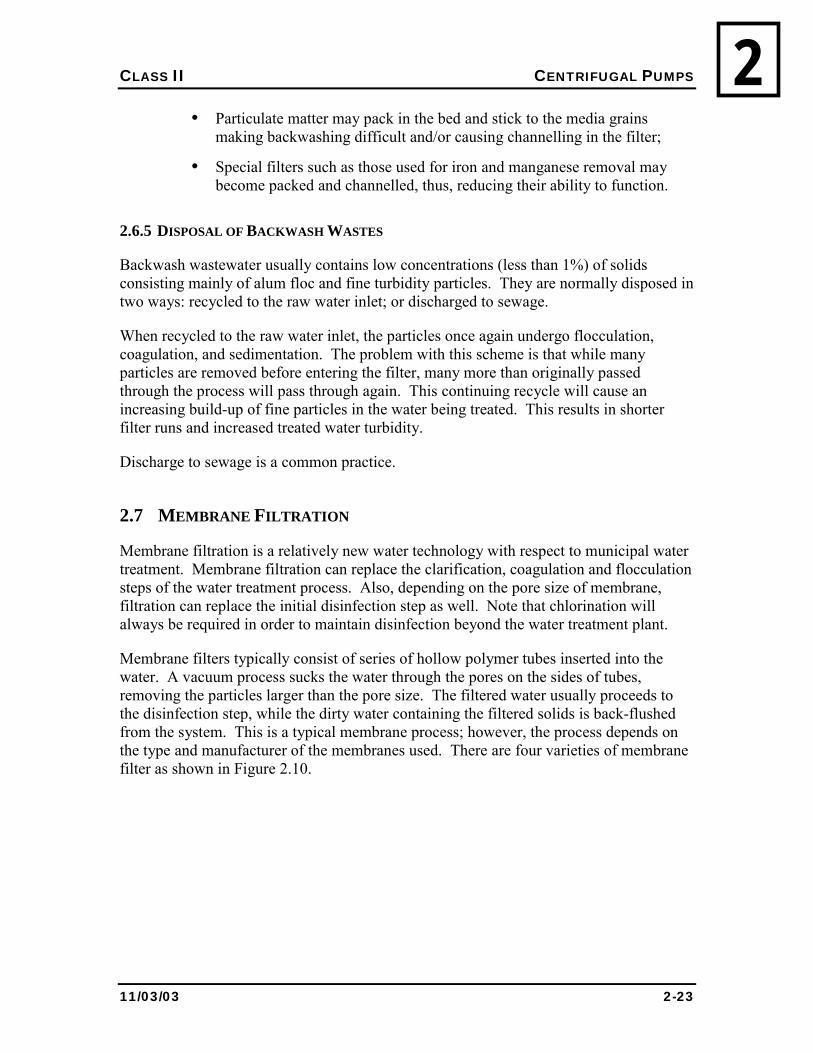
2Figure 2-10 Membrane Filtration Varieties
(Note: Pore size varies with manufacturer, typical values are shown)
• Microfiltration only removes bacteria and cysts, but not viruses, it is not
suitable as a disinfection step, but rather its main use is in particulate removal.
• Ultrafiltration can be classified as both a clarification and initial disinfection step since it will remove all microorganisms. Chlorination will still be required in order to maintain a residual.
• Nanofiltration is designed to remove multivalent cations such as calcium, iron and magnesium as well as disinfection and clarification. Chlorination will still be required in order to maintain a residual.
Nanofiltration is a replacement for conventional iron and manganese removal methods such as greensand filtration.
• Reverse-osmosis membranes are designed for salt removal especially as applied to seawater sources. Their use for small-scale water treatment processes is currently limited. Chlorination will still be required in order to maintain a residual.
Filter pressure requirements increase as the pore size of the filter is reduced. For example, reverse-osmosis requires a filter pressure of up to 1200 psi, while ultrafiltration can use pressures as low as 2 psi.
Similar to conventional filters, membrane filters require backwashing. However, membrane filters suffer from a condition known as membrane fouling. Membrane fouling occurs when colloids, salts, bacteria or other substances clog themselves in the
CLASS II CENTRIFUGAL PUMPS
11/03/03 2-25
2pores of the filters. Fouling can be controlled by the addition of chemical additives. Additives are chosen based on the source of fouling.
Eventually, most filter membranes must be cleaned after they are sufficiently fouled, which is done by removing the membrane from the system and cleaning it with a membrane cleaning solution.
2.8 WATER HARDNESS
2.8.1 INTRODUCTION TO HARDNESS
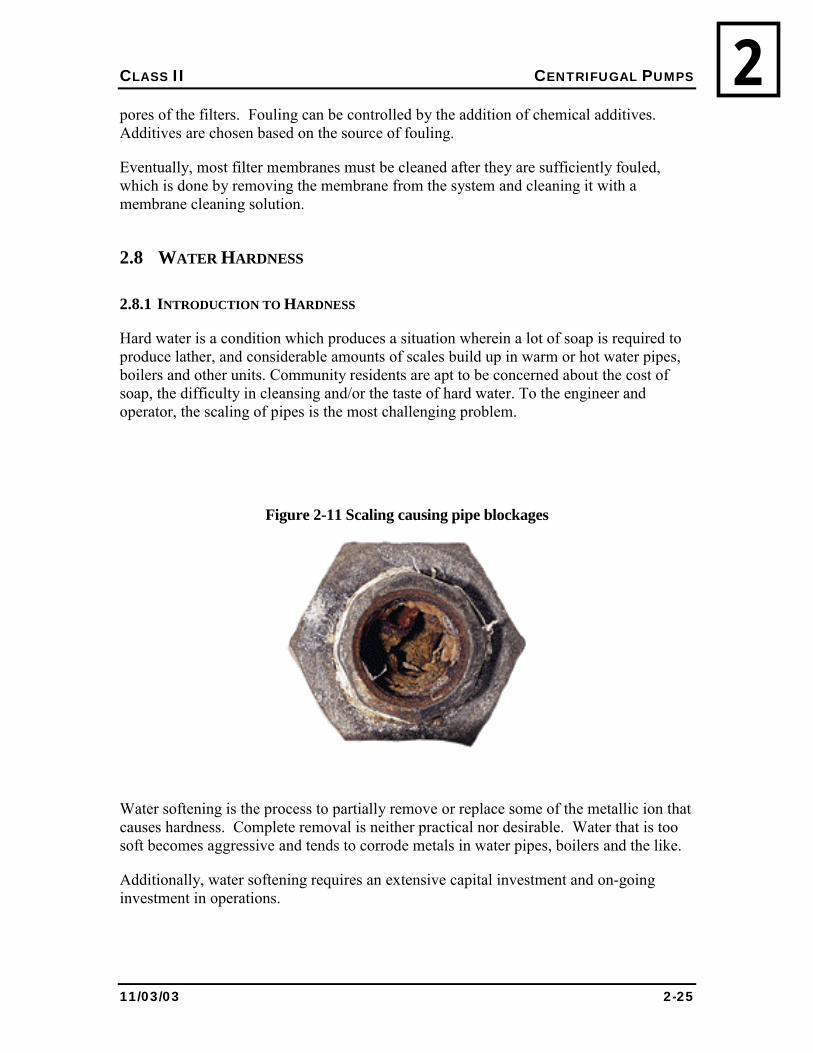
Hard water is a condition which produces a situation wherein a lot of soap is required to produce lather, and considerable amounts of scales build up in warm or hot water pipes, boilers and other units. Community residents are apt to be concerned about the cost of soap, the difficulty in cleansing and/or the taste of hard water. To the engineer and operator, the scaling of pipes is the most challenging problem.
Figure 2-11 Scaling causing pipe blockages
Water softening is the process to partially remove or replace some of the metallic ion that causes hardness. Complete removal is neither practical nor desirable. Water that is too soft becomes aggressive and tends to corrode metals in water pipes, boilers and the like.
Additionally, water softening requires an extensive capital investment and on-going investment in operations.
CLASS II CENTRIFUGAL PUMPS
11/03/03 2-26
2Table 2-5 Water Classifications in Terms of the Degree of Hardness
Calcium Carbonate (CaCO3) Range
Classification
0 to 45 mg/l Very soft
45 to 90 mg/l Soft
90 to 130 mg/l Moderately hard
130 to 170 mg/l Hard
170 to 250 mg/l Very hard
250 + mg/l Excessively hard (too hard for most domestic uses)
2.8.2 CAUSES OF HARDNESS
Hardness is caused by divalent metallic ions. The principal hardness-causing ions are calcium, magnesium, strontium, ferrous iron, manganous ions. These cations in combination with the most important anions are shown as follows:
Figure 2-12 Cations and anions
Cations Anions
Ca2+ HCO3-
Mg2+ SO42-
Sr2+ Cl-
Fe2+ NO3-
Mn2+ SiO32-
Rainwater is capable of dissolving tremendous amounts of solids found in many natural formations. This explains why hardness is usually associated with ground water, but why surface waters can fluctuate in hardness depending on the weather and the time of year.
In general, hard waters originate in areas where the topsoil is thick and limestone formations are present. Soft waters originate in areas where the topsoil is thin and limestone formations are sparse or absent.
CLASS II CENTRIFUGAL PUMPS
11/03/03 2-27
22.8.3 CALCULATING HARDNESS
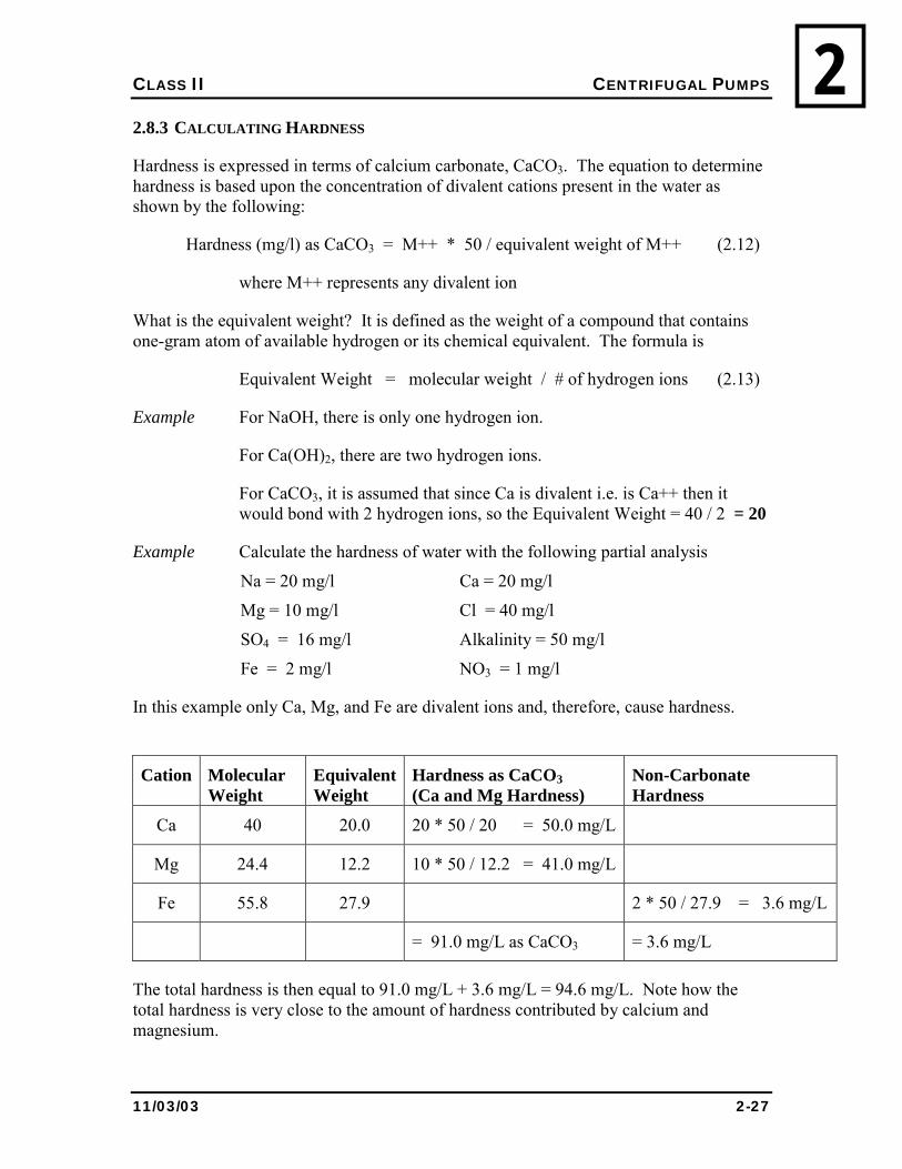
Hardness is expressed in terms of calcium carbonate, CaCO3. The equation to determine hardness is based upon the concentration of divalent cations present in the water as shown by the following:
Hardness (mg/l) as CaCO3 = M++ * 50 / equivalent weight of M++ (2.12)
where M++ represents any divalent ion
What is the equivalent weight? It is defined as the weight of a compound that contains one-gram atom of available hydrogen or its chemical equivalent. The formula is
Equivalent Weight = molecular weight / # of hydrogen ions (2.13)
Example For NaOH, there is only one hydrogen ion.
For Ca(OH)2, there are two hydrogen ions.
For CaCO3, it is assumed that since Ca is divalent i.e. is Ca++ then it would bond with 2 hydrogen ions, so the Equivalent Weight = 40 / 2 = 20
Example Calculate the hardness of water with the following partial analysis
Na = 20 mg/l Ca = 20 mg/l
Mg = 10 mg/l Cl = 40 mg/l
SO4 = 16 mg/l Alkalinity = 50 mg/l
Fe = 2 mg/l NO3 = 1 mg/l
In this example only Ca, Mg, and Fe are divalent ions and, therefore, cause hardness.
Cation Molecular Weight
Equivalent Weight
Hardness as CaCO3 (Ca and Mg Hardness)
Non-Carbonate Hardness
Ca 40 20.0 20 * 50 / 20 = 50.0 mg/L
Mg 24.4 12.2 10 * 50 / 12.2 = 41.0 mg/L
Fe 55.8 27.9 2 * 50 / 27.9 = 3.6 mg/L
= 91.0 mg/L as CaCO3 = 3.6 mg/L
The total hardness is then equal to 91.0 mg/L + 3.6 mg/L = 94.6 mg/L. Note how the total hardness is very close to the amount of hardness contributed by calcium and magnesium.
CLASS II CENTRIFUGAL PUMPS
11/03/03 2-28
22.8.4 TYPES OF HARDNESS
Hardness is classified in two ways: 1) with respect to the metallic ion and 2) with respect to the associated anions.
Calcium and magnesium hardness is by far the greatest proportion of hardness occurring in natural waters. In general, a close enough approximation is:
Total hardness = calcium hardness + magnesium hardness (2.13)
Carbonate and non-carbonate hardness. Carbonate hardness is an important consideration as the carbonate and bicarbonate ions tend precipitate at elevated temperatures such as are found in boilers. Non-carbonate hardness used to be called permanent hardness because it cannot be removed or precipitated by boiling.
When the alkalinity is less than the total hardness, then the carbonate hardness is equal to the alkalinity. When the alkalinity is equal to or greater than the total hardness, the carbonate hardness equals the total hardness.
2.9 ALKALINITY
2.9.1 INTRODUCTION TO ALKALINITY
Alkalinity is the capacity of water to neutralize acids, and is a measure of how much acid can be added to water without causing a great change in the pH. Alkalinity is a result of, and therefore classified by, the anions: carbonate, bicarbonate, and hydroxide. Although alkalinity has little sanitary significance, highly alkaline waters are generally unpalatable and thus customers tend to seek other, potentially unsafe, water supplies.
2.9.2 CALCULATING ALKALINITY
Alkalinity is measured volumetrically by titration, adding sulphuric acid to a test sample. For samples with a pH greater than 8.3, the titration is done in two steps. In the first step of titration, a liquid pH indicator called phenolphthalein is added to the solution and will turn colourless from its original pink colour when the pH reaches 8.3. In the second step, a pH indicator added called methyl orange will change colour when the pH 4.5.
When the pH of a sample is less than 8.3, only the second step is used.
2.9.3 APPLICATION OF ALKALINITY DATA
Chemical coagulation causes insoluble hydroxide precipitates. Also released are hydrogen ions that react with the alkalinity to the water. Alkalinity must be present in excess of what is destroyed for effective and complete coagulation to take place.
CLASS II CENTRIFUGAL PUMPS
11/03/03 2-29
2Water softening is done by adding lime or soda. The exact amount of lime or soda required is determined by the current alkalinity of the water.
Corrosion control requires that alkalinity is considered. For example, alkalinity must be known in order to calculate the Langlier saturation index (defined in 2.12.3).
2.10 TASTE & ODOUR CONTROL
2.10.1 INTRODUCTION
Bad tastes and odours are the most common causes of consumer complaints. The North has many examples of people collecting their own water because they don�t like the taste of the public supply.
This is both unfortunate and dangerous, as the public water supply is the only water source that is properly disinfected and that meets all the health based drinking water parameters.
If people won�t drink from the �safe� public supply, then what good is it? From the public�s perspective, aesthetic parameters such as taste and odour rank with the health based parameters. Considering the other concoctions the public willingly drinks, aesthetic parameters are an important consideration, and should receive more attention.
2.10.2 CAUSES OF TASTE & ODOUR
Dissolved gases such as hydrogen sulphide are common in ground waters and can be present in deep, ice-covered lakes or reservoirs.
Biological growths such as algae, bacteria, and slimes can be found through a system, from source to customer. They contribute in a number of ways: the living organism may have an objectionable taste; the living organism produces objectionable by-products; the dead organism releases internal cell materials; chemically combined with treatment chemicals such as chlorine, internal cell materials contribute to taste and odour.
A product of decaying algae and vegetation is a natural phenomenon and part of nature�s recycling program.
Contaminants from industrial discharges are not much of a problem in the North. However, storm runoff and spring break up can cause problems, especially when the increased turbidity gets through the plant.
Problems in the distribution system: in piped systems, bacterial growth, areas of low flow and corroded pipes can contribute to taste and odour. Complaint records should be kept so these areas can be identified and measures such as hydrant flushing can be undertaken.
CLASS II CENTRIFUGAL PUMPS
11/03/03 2-30
2In trucked systems, complaints often result from dirty water tanks in the residence and improperly cleaned water trucks.
Chemicals used in treatment can impart taste and odour if used in excess and not properly controlled. Chlorine taste and smell seems to lead the list of complaints. Ensure that your free chlorine residual is in the proper range.
Minerals such as iron and manganese can impart an objectionable taste and odour if in excess of the aesthetic guidelines.
2.10.3 TASTE AND ODOUR TREATMENT
Improved coagulation/flocculation can be helpful depending on the cause of taste and odour. This is particularly true when the problem is a result of sudden changes in the raw water source.
Aeration with spray, cascade, or draft aerators is normally used to release trapped gases such as hydrogen sulphide, methane, and other volatile gases. Aeration has little or no effect on non-volatile substances. Aeration of raw water sources using a bubbler, especially under ice cover, is a method of reducing both volatile gases and biological growths.
Activated Carbon is used to absorb taste and odour compounds. Granular activated carbon (GAC) is commonly used in towers and/or filters and is either discarded or recharged when the taste and odour compounds break through the carbon. Powdered activated carbon (PAC) is added to the water at some point before the filtration process. After it has done its work it is removed either in sedimentation or in filtration and discarded. There is no way to regenerate PAC. PAC is often less effective in removing chlorinated compounds, so post-chlorination should be conducted.
Chemical oxidation uses oxidation compounds to destroy the objectionable compound or change it into a less objectionable form. Four chemicals are commonly used: chlorine, potassium permanganate, chlorine dioxide, and ozone. If this process is to be used, chemical selection is important. Chlorine, for example, can make an objectionable compound even more objectionable. Laboratory testing should be used to select a chemical for oxidation. For example, hydrogen sulphide, which produces a rotten-egg smell, can be controlled by the addition of potassium permanganate.
2.11 IRON AND MANGANESE CONTROL
2.11.1 INTRODUCTION
Ground water, such as that found in Wha Ti, Fort Liard and Nahanni Butte, often contains iron and manganese. Although usually referenced together, they can be found
CLASS II CENTRIFUGAL PUMPS
11/03/03 2-31
2separately. Typical concentrations for iron and manganese are 10 ppm and 2 ppm, respectively.
Neither element has any direct adverse health effects for humans. Both are found in multivitamins; however, iron and manganese in normal drinking water have no nutrient value. For the water to contain beneficial amounts, the taste of the water would be rather unpleasant.
Clothes laundered in water containing iron or manganese above certain concentrations often come out stained. They can also lead to stains on plumbing fixtures such as sinks and toilets.
The biggest problem, however, is that they promote the growth of a group of organisms called autotrophic. These bacteria use non-carbon sources such as iron and manganese for their food. They form thick slime layers inside pipes and storage tanks. These slime layers can cause their own problems when they become loose and create dirty water and customer complaints. But the slime layers also consume chlorine and can harbour pathogenic organisms.
2.11.2 REGULATORY REQUIREMENT
There is no regulatory requirement for iron and manganese. The Guidelines state an aesthetic objective of 0.3 mg/l for iron, and 0.05 mg/l for manganese.
2.11.3 TREATMENT METHODS
2.11.3.1 Oxidation by Aeration
Metallic iron, found in water, can be oxidized by aeration to form insoluble ferric hydroxide. The reaction rate depends on the pH of water. The higher the pH, the shorter the treatment time. Often, small quantities of lime, sodium carbonate or sodium hydroxide are added to increase the pH.
There are several methods to provide aeration. Either the water being treated is dispersed into the air, or the air is bubbled through the water. Most commonly, aeration is achieved by using compressed air, which passes through diffusers in the water creating small bubbles capable of oxidizing the iron in the water. There are also waterfall or cascade aerators that are a series of small waterfalls that provide an opportunity for air to contact the water. Spray aerators are also used, which uses jets of fine spray that provide contact between the air and water.
Following aeration, the water is passed to a reaction basin. The basin is a usually cylindrical shaped basin similar to a clarifier. It is present to allow sufficient time for the oxidization process to occur. Usually, reactions take around 30 to 60 minutes. The basin must be cleaned regularly to avoid sludge build up that could clog the filters. The basins
CLASS II CENTRIFUGAL PUMPS
11/03/03 2-32
2must be covered at all times and all vents must be properly screened. An air gap must be present to avoid contamination resulting from backflow.
After the ferric hydroxide forms in the settling tank, it is removed either by sedimentation or filtration, where the rest of the water continues throughout the water treatment process.
ADVANTAGES ! No chemicals are usually required, unless pH adjustment is required.
DISADVANTAGES ! Small changes in surface water pH will have a drastic effect on iron removal
efficiency;
! Manganese oxidization efficiency is very low and hence, this treatment method is not valid where manganese concentrations are high;
! Humidity issues may occur is open aeration is used;
! Higher costs.
2.11.3.2 Chlorination
Chlorine will oxidize both iron and manganese to their insoluble forms. The higher the chlorine residual in the water, the faster the reaction is. For typical iron and manganese removal needs, first you treat the water with an initial chlorine residual of 5 to 10 mg/L, then filter the insoluble iron and manganese formed and then finally dechlorinate the water to an acceptable residual for domestic use.
Doses beyond 10 mg/L can causes excess concentrations of total trihalomethanes (TTHMs), which can cause adverse health conditions.
Filtration of the insoluble iron and manganese can be done in the same method as outlined in the �oxidization by aeration� treatment method. The dechlorination uses a reducing agent such as sodium bisulphate to remove the excess chlorine.
Usually a reaction basin is added after the dechlorination process in a similar matter done by the �oxidization by aeration� treatment process to allow for sufficient time for the oxidization to occur.
ADVANTAGES ! Removes both iron and manganese from the water.
Disadvantages ! Requires additional chemicals with exact dosages;
! Requires an additional dechlorination step to the water treatment process.
CLASS II CENTRIFUGAL PUMPS
11/03/03 2-33
22.11.3.3 Manganese Greensand Filter
A manganese greensand filter is capable of removing both iron and manganese from the water. A greensand filter is very similar to a regular sand filter except that the granular material has been treated with potassium permanganate.
The filter can be operated in three modes:
1. Continuous Regeneration,
2. Intermittent Regeneration, and
3. Catalytic Regeneration.
2.11.3.3.1 Continuous Regeneration
In the continuous regeneration process, chlorine is first added, oxidizing most of the metallic iron and manganese present in the raw water. Then a slight excess of potassium permanganate is added to remove the rest of iron and manganese. Finally, the water is passed through the Greensand filter where two things occur: (1) the insoluble iron and manganese oxides are filtered and (2) the excess permanganate is reduced to manganese oxides, regenerating the greensand. Once the head loss is too high through the filter, the filter is then backwashed.
ADVANTAGES ! Can remove moderate concentrations of manganese and iron in the water.
DISADVANTAGES ! Requires the addition of chlorine and if required, a dechlorination step;
! Manganese oxidization efficiency is very low and hence, this treatment method is not valid where manganese concentrations are high.
2.11.3.3.2 Intermittent Regeneration (IR)
The intermittent regeneration process is suitable where mostly manganese is present, having very little iron in the raw water. Oxidation occurs directly on the greensand as raw water flows over it. In this process small amounts of iron are also removed. Lastly, the filter is backwashed when the head loss becomes too large.
ADVANTAGES ! Suitable for situations where manganese removal is the main treatment
requirement;
! Does not require chlorine or dechlorination.
CLASS II CENTRIFUGAL PUMPS
11/03/03 2-34
2DISADVANTAGES
! Cannot effectively treat water with significant iron concentrations;
! Filter must be backwashed frequently.
2.11.3.3.3 Catalytic Regeneration
Catalytic Regeneration is suitable where iron and manganese concentrations are small, less than 1.0mg/L and where the pH is greater than 7.0. Sufficient chlorine is added to the raw water before the filter to maintain a chlorine residual of 0.5 to 1.0 mg/L. As the water passes though a special grade of greensand, the chlorine regenerates the greensand and the manganese is oxidized right on the filter.
ADVANTAGES ! Suitable for situations where iron and manganese concentrations are relatively
low and the pH is above 7.0;
! Longer filter run lengths are observed in comparison with the previous two methods;
! Low chemical operating costs;
! Low suspended solids in backwash wastes.
DISADVANTAGES ! Cannot treat water with high iron and manganese concentration;
! Requires a specially refined greensand, often Pyrolox.
2.11.4 OPERATION OF A MANGANESE GREENSAND FILTER
Most plants use a continuous regeneration greensand filter for iron and manganese removal. This section will look into the operation of this specific type of greensand filter. Since iron and manganese removal can often be a fairly expensive process, it is important for the operator to understand the treatment process as well as how to identify when something goes wrong or when concentrations are exceeded.
2.11.4.1 Equipment
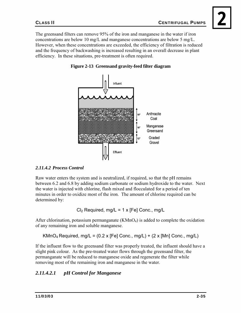
The filter usually consists of 3 different types of layers. One layer on top consists of 45 cm (18 inches) of anthracite coal, followed by 45 cm of manganese greensand, with 30 cm (12 inches) of graded gravel on the bottom. The greensand filter is different from a conventional sand filter as the greensand contains much finer sand, having a slower filtering and backwash rate.
CLASS II CENTRIFUGAL PUMPS
11/03/03 2-35
2The greensand filters can remove 95% of the iron and manganese in the water if iron concentrations are below 10 mg/L and manganese concentrations are below 5 mg/L. However, when these concentrations are exceeded, the efficiency of filtration is reduced and the frequency of backwashing is increased resulting in an overall decrease in plant efficiency. In these situations, pre-treatment is often required.
Figure 2-13 Greensand gravity-feed filter diagram
2.11.4.2 Process Control
Raw water enters the system and is neutralized, if required, so that the pH remains between 6.2 and 6.8 by adding sodium carbonate or sodium hydroxide to the water. Next the water is injected with chlorine, flash mixed and flocculated for a period of ten minutes in order to oxidize most of the iron. The amount of chlorine required can be determined by:
Cl2 Required, mg/L = 1 x [Fe] Conc., mg/L
After chlorination, potassium permanganate (KMnO4) is added to complete the oxidation of any remaining iron and soluble manganese.
KMnO4 Required, mg/L = (0.2 x [Fe] Conc., mg/L) + (2 x [Mn] Conc., mg/L)
If the influent flow to the greensand filter was properly treated, the influent should have a slight pink colour. As the pre-treated water flows through the greensand filter, the permanganate will be reduced to manganese oxide and regenerate the filter while removing most of the remaining iron and manganese in the water.
2.11.4.2.1 pH Control for Manganese
CLASS II CENTRIFUGAL PUMPS
11/03/03 2-36
2Manganese is often more difficult to remove when compared to iron and H2S. During commissioning of the Nahanni plant a bench study showed that raw water pH had to be increased from about pH 8 to over pH 9 to see some reduction of manganese.
For your safety
Do not allow Potassium Permanganate to come with alcohols, powdered metals or sulphuric powders. Keep away from open flames and areas of high heat. Wear gloves, goggles and a surgical mask when working with the chemical.
2.11.4.2.2 Backwashing
Backwashing should occur when the head loss reaches about 69 kpa (10 psi.) and the duration of the backwash should be around 10 to 15 minutes allowing the system to unclog the settled insoluble iron and manganese oxides trapped in the filter. Filter cracking can occur which will affect apparent head loss. Filters should be backwashed everyday, but no less than every 2 days to prevent cracking.
It is very important not to underfeed the amount of permanganate added to the pre-treatment process or else the greensand filter will lose its oxidative properties. However, if the potassium permanganate charge is somehow lost in the filter, the operator can regenerate the greensand manually. The filter must be first shut down. Then, a saturated solution of potassium permanganate (around 5%) is poured into the filters and left to sit for 24 hours.
After 24 hours, the system is backwashed and restarted. Another way the system can be recharged without shutting down is by increasing the potassium permanganate dosage until pink water flows out of the bottom of the greensand filter. When the pink water flows out of the filter, the filter is recharged and regular doses of potassium permanganate can continue.
The operator should perform iron, manganese, pH and chlorine residual tests on a daily basis in order to determine if there are any problems in the system.
Remember, the above is only meant as a guide. Specific backwash requirement are site and equipment specific. Refer to manufacturer specification and procedures as they relate to your plant.
For your safety
When mixing, always add chemicals to water. Never add water to chemicals.
CLASS II CENTRIFUGAL PUMPS
11/03/03 2-37
22.12 DISINFECTION
2.12.1 HYPOCHLORINATION
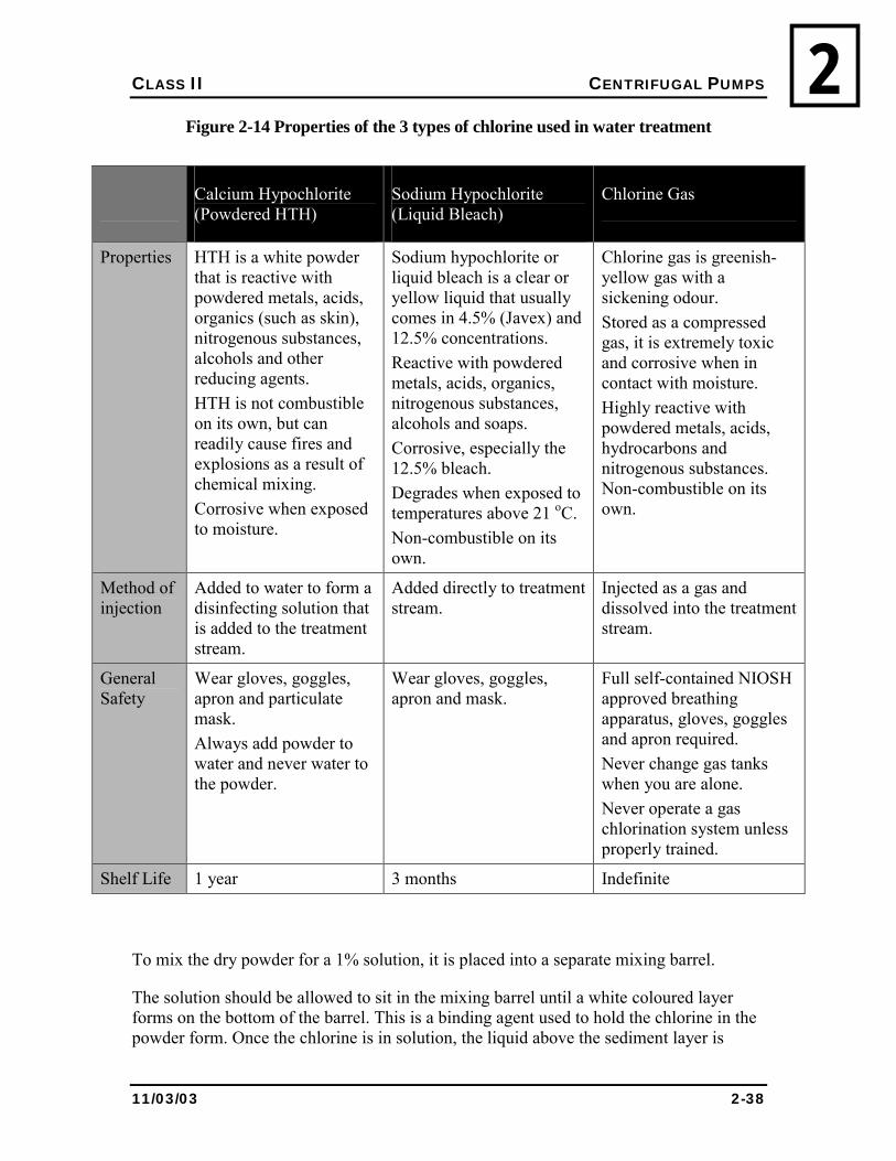
There are two common sources of chlorine injected into water supplies to disinfect it. They are:
! Calcium Hypochlorite; ! Sodium Hypochlorite, also known as liquid bleach.
The other source of chlorine is chlorine gas, which is not commonly used in small systems plants. Properties of the varying chlorine sources are shown in Table 2-14. Calcium Hypochlorite is also known as HTH (High Test Hypochlorite). It is manufactured in tablet, liquid, powder or granular form. Over time, HTH will lose its strength. It can lose up to 10% of its strength in a year.
Should it get wet, it will lose its strength much more rapidly. As it deteriorates it gives off heat. If it comes in contact with an oily rag or cardboard, a fire could result. HTH must be kept dry and separate from other materials.
FOR YOUR OWN SAFETY
Water should be first placed in the mixing barrel and then the HTH should be added. HTH should never be placed in the mixing barrel first and the water added, to avoid dangerous spraying or spilling of chemicals.
You must avoid contact with the HTH dust because it turns into an acid when it gets wet and it will burn your skin and your eyes. If you breathe it in, it will burn your nasal passages and your lungs. You must wear rubber gloves, an apron, and nose and eye protection when you are working with the dry chemical or the mixed solution. There must also be a proper eyewash facility nearby.
CLASS II CENTRIFUGAL PUMPS
11/03/03 2-38
2Figure 2-14 Properties of the 3 types of chlorine used in water treatment
Calcium Hypochlorite (Powdered HTH)
Sodium Hypochlorite (Liquid Bleach)
Chlorine Gas
Properties HTH is a white powder that is reactive with powdered metals, acids, organics (such as skin), nitrogenous substances, alcohols and other reducing agents. HTH is not combustible on its own, but can readily cause fires and explosions as a result of chemical mixing. Corrosive when exposed to moisture.
Sodium hypochlorite or liquid bleach is a clear or yellow liquid that usually comes in 4.5% (Javex) and 12.5% concentrations. Reactive with powdered metals, acids, organics, nitrogenous substances, alcohols and soaps. Corrosive, especially the 12.5% bleach. Degrades when exposed to temperatures above 21 oC. Non-combustible on its own.
Chlorine gas is greenish-yellow gas with a sickening odour. Stored as a compressed gas, it is extremely toxic and corrosive when in contact with moisture. Highly reactive with powdered metals, acids, hydrocarbons and nitrogenous substances. Non-combustible on its own.
Method of injection
Added to water to form a disinfecting solution that is added to the treatment stream.
Added directly to treatment stream.
Injected as a gas and dissolved into the treatment stream.
General Safety
Wear gloves, goggles, apron and particulate mask. Always add powder to water and never water to the powder.
Wear gloves, goggles, apron and mask.
Full self-contained NIOSH approved breathing apparatus, gloves, goggles and apron required. Never change gas tanks when you are alone. Never operate a gas chlorination system unless properly trained.
Shelf Life 1 year 3 months Indefinite
To mix the dry powder for a 1% solution, it is placed into a separate mixing barrel.
The solution should be allowed to sit in the mixing barrel until a white coloured layer forms on the bottom of the barrel. This is a binding agent used to hold the chlorine in the powder form. Once the chlorine is in solution, the liquid above the sediment layer is
CLASS II CENTRIFUGAL PUMPS
11/03/03 2-39
2slowly siphoned into the feed barrel. The sediment left in the mixing barrel should be thrown out because it will clog the chemical feed pump and the small tubing.
Sodium Hypochlorite is also known as liquid bleach. Two types are available: a high strength 12%; or regular strength 4.5% bleach (Javex or Purex are two trade names) available in any grocery store. Unlike HTH, bleach can be mixed directly into the mixing barrel without fear of clogging the pump or the tubing. Sodium hypochlorite deteriorates very rapidly (60 to 90 days), especially when exposed to light, and so it should be stored in a cool, dry, dark area
FOR YOUR OWN SAFETY
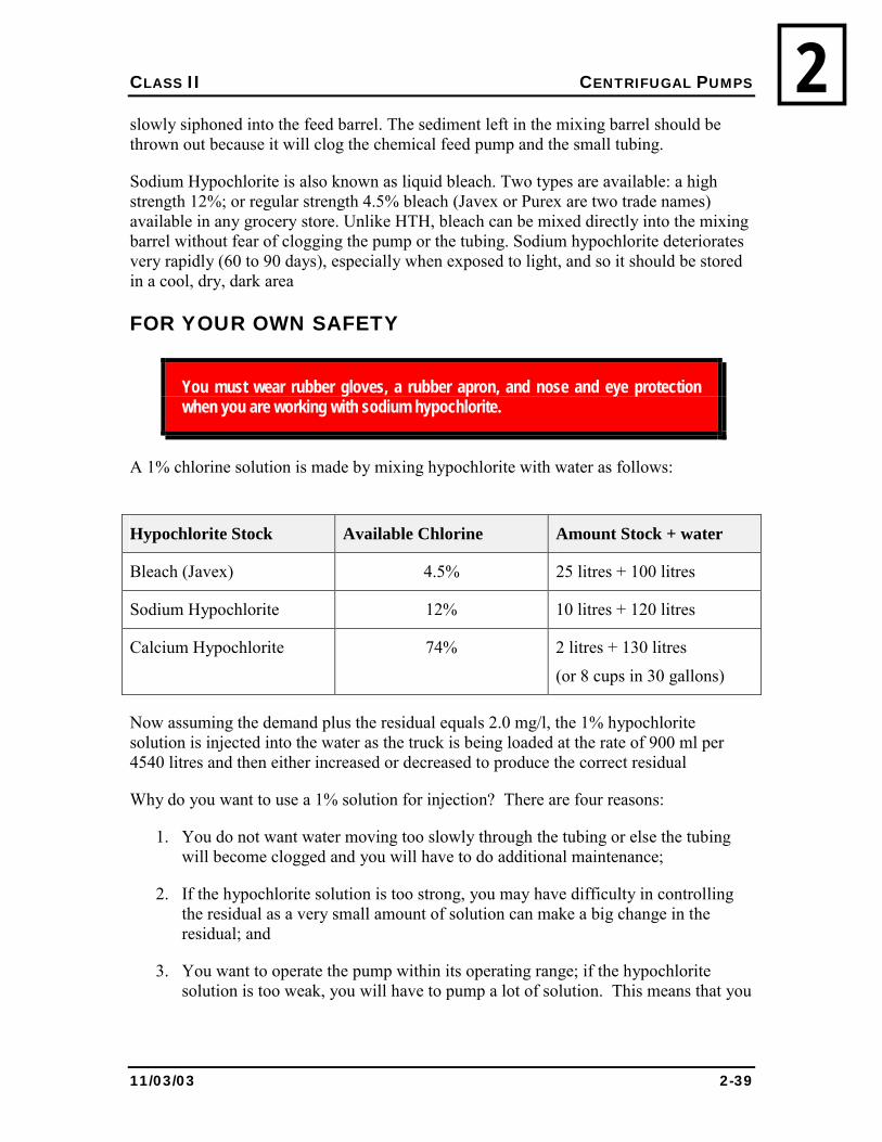
You must wear rubber gloves, a rubber apron, and nose and eye protection when you are working with sodium hypochlorite.
A 1% chlorine solution is made by mixing hypochlorite with water as follows:
Hypochlorite Stock Available Chlorine Amount Stock + water
Bleach (Javex) 4.5% 25 litres + 100 litres
Sodium Hypochlorite 12% 10 litres + 120 litres
Calcium Hypochlorite 74% 2 litres + 130 litres
(or 8 cups in 30 gallons)
Now assuming the demand plus the residual equals 2.0 mg/l, the 1% hypochlorite solution is injected into the water as the truck is being loaded at the rate of 900 ml per 4540 litres and then either increased or decreased to produce the correct residual
Why do you want to use a 1% solution for injection? There are four reasons:
1. You do not want water moving too slowly through the tubing or else the tubing will become clogged and you will have to do additional maintenance;
2. If the hypochlorite solution is too strong, you may have difficulty in controlling the residual as a very small amount of solution can make a big change in the residual; and
3. You want to operate the pump within its operating range; if the hypochlorite solution is too weak, you will have to pump a lot of solution. This means that you
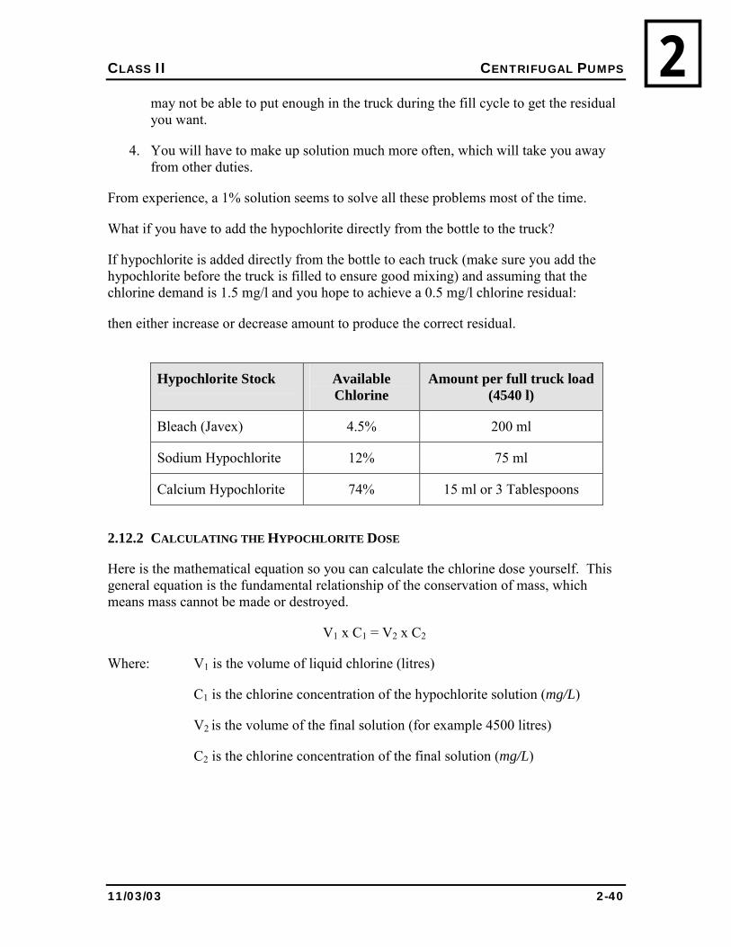
CLASS II CENTRIFUGAL PUMPS
11/03/03 2-40
2may not be able to put enough in the truck during the fill cycle to get the residual you want.
4. You will have to make up solution much more often, which will take you away from other duties.
From experience, a 1% solution seems to solve all these problems most of the time.
What if you have to add the hypochlorite directly from the bottle to the truck?
If hypochlorite is added directly from the bottle to each truck (make sure you add the hypochlorite before the truck is filled to ensure good mixing) and assuming that the chlorine demand is 1.5 mg/l and you hope to achieve a 0.5 mg/l chlorine residual:
then either increase or decrease amount to produce the correct residual.
Hypochlorite Stock Available Chlorine
Amount per full truck load (4540 l)
Bleach (Javex) 4.5% 200 ml
Sodium Hypochlorite 12% 75 ml
Calcium Hypochlorite 74% 15 ml or 3 Tablespoons
2.12.2 CALCULATING THE HYPOCHLORITE DOSE
Here is the mathematical equation so you can calculate the chlorine dose yourself. This general equation is the fundamental relationship of the conservation of mass, which means mass cannot be made or destroyed.
V1 x C1 = V2 x C2
Where: V1 is the volume of liquid chlorine (litres)
C1 is the chlorine concentration of the hypochlorite solution (mg/L)
V2 is the volume of the final solution (for example 4500 litres)
C2 is the chlorine concentration of the final solution (mg/L)
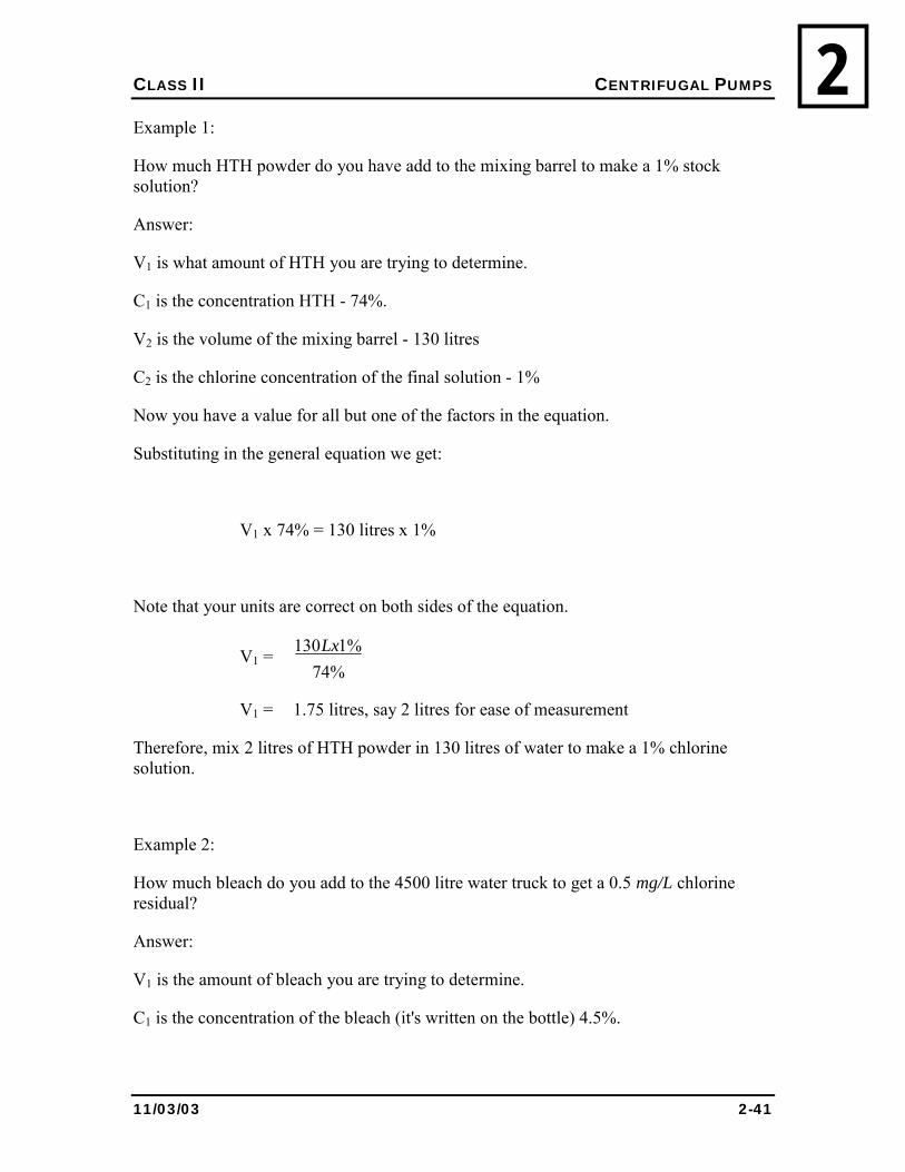
CLASS II CENTRIFUGAL PUMPS
11/03/03 2-41
2Example 1:
How much HTH powder do you have add to the mixing barrel to make a 1% stock solution?
Answer:
V1 is what amount of HTH you are trying to determine.
C1 is the concentration HTH - 74%.
V2 is the volume of the mixing barrel - 130 litres
C2 is the chlorine concentration of the final solution - 1%
Now you have a value for all but one of the factors in the equation.
Substituting in the general equation we get:
V1 x 74% = 130 litres x 1%
Note that your units are correct on both sides of the equation.
V1 = %74
%1130Lx
V1 = 1.75 litres, say 2 litres for ease of measurement
Therefore, mix 2 litres of HTH powder in 130 litres of water to make a 1% chlorine solution.
Example 2:
How much bleach do you add to the 4500 litre water truck to get a 0.5 mg/L chlorine residual?
Answer:
V1 is the amount of bleach you are trying to determine.
C1 is the concentration of the bleach (it's written on the bottle) 4.5%.
CLASS II CENTRIFUGAL PUMPS
11/03/03 2-42
2V2 is the volume of the truck - 4500 litres
C2 is the chlorine concentration of the final solution (mg/L) where the concentration is the sum of the:
chlorine demand + chlorine residual
For now, assume the demand is 1.5 mg/L
Therefore, C2 is 1.5 mg/L + 0.5 mg/L = 2.0 mg/L
Now we have a value for all but one of the factors in the equation.
Substituting in the general equation we get:
V1 x 4.5% = 4500 litres x 2.0 mg/L
But you cannot solve this problem yet because the chlorine concentration C1 is in percent and it should be in mg/L. What is 4.5% in mg/L?
A percent is the amount per one hundred. So, 4.5% is:
4.5 parts per 100
A rule of thumb is 1 mg/L is the same as 1 part per million (ppm). If 4.5% is 4.5 per 100, how much is that per million? You can determine this by using a simple ratio. You write the ratio like this:
000,000,1?
1005.4 =
Rearranging this equation to solve for ?, you get:
100000,000,15.4? ×=
? = 45,000
Therefore, 4.5% is equal to 45,000 parts per million. Recalling 1 mg/L is the same as 1 part per million, then 4.5% is equal to 45,000 mg/L.
Now substituting in the equation we get:
V1 x 45,000 mg/L = 4500 litres x 2.0 mg/L
Rearranging this equation to solve for V1, we get:
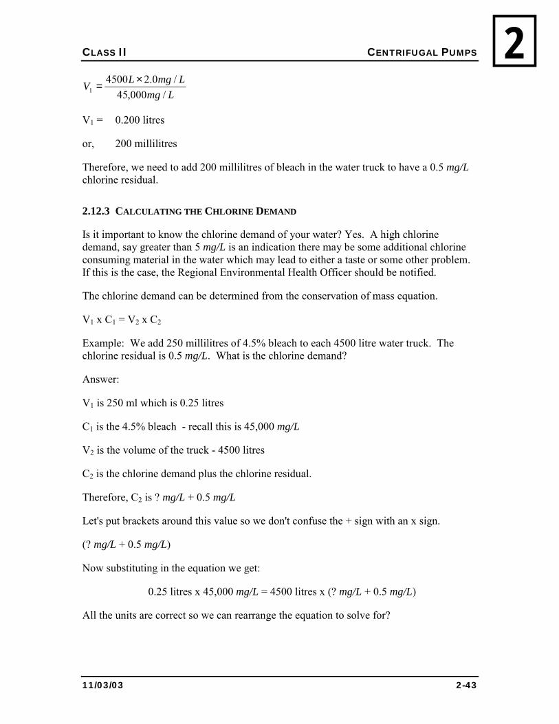
CLASS II CENTRIFUGAL PUMPS
11/03/03 2-43
2Lmg
LmgLV/000,45
/0.245001
×=
V1 = 0.200 litres
or, 200 millilitres
Therefore, we need to add 200 millilitres of bleach in the water truck to have a 0.5 mg/L chlorine residual.
2.12.3 CALCULATING THE CHLORINE DEMAND
Is it important to know the chlorine demand of your water? Yes. A high chlorine demand, say greater than 5 mg/L is an indication there may be some additional chlorine consuming material in the water which may lead to either a taste or some other problem. If this is the case, the Regional Environmental Health Officer should be notified.
The chlorine demand can be determined from the conservation of mass equation.
V1 x C1 = V2 x C2
Example: We add 250 millilitres of 4.5% bleach to each 4500 litre water truck. The chlorine residual is 0.5 mg/L. What is the chlorine demand?
Answer:
V1 is 250 ml which is 0.25 litres
C1 is the 4.5% bleach - recall this is 45,000 mg/L
V2 is the volume of the truck - 4500 litres
C2 is the chlorine demand plus the chlorine residual.
Therefore, C2 is ? mg/L + 0.5 mg/L
Let's put brackets around this value so we don't confuse the + sign with an x sign.
(? mg/L + 0.5 mg/L)
Now substituting in the equation we get:
0.25 litres x 45,000 mg/L = 4500 litres x (? mg/L + 0.5 mg/L)
All the units are correct so we can rearrange the equation to solve for?
CLASS II CENTRIFUGAL PUMPS
11/03/03 2-44
2( )
LLmgLLmgLmg
4500/000,4525.0/5.0/? ×=+
LLmgLLmg
4500/000,4525.0/? ×=
? mg / L = 2.0 mg / L
Therefore, the chlorine demand for our example water is 2.0 mg/L.
2.12.4 GAS CHLORINATION
Shown in Figure 2.15 and/or Figure 2.16, typical components of a gas chlorine system are described as follows:
1. The cylinder valve is opened to allow pressurized chlorine gas to enter the chlorinator;
2. The inlet regulating valve controls the down stream gas pressure;
3. The pressure relief valve allows gas to pass only when a vacuum exists on the downstream side of the valve. If the vacuum is interrupted, the pressure relief valve exhausts chlorine through the vent line;
4. The flow rate indicator, typically a rotameter, measures the chlorine flow rate;
5. The rate valve consists of an orifice that is adjusted to control the chlorine flow rate;
6. The outlet regulating valve ensures that the vacuum remains steady so that a constant flow rate is maintained;
7. The check valve prevents process water from entering the chlorinator;
8. The injector/ejector diffuses the chlorine gas into the process water. A vacuum is created in the injector by the process water flowing through a venturi.
Gas chlorinators are either cabinet mounted, or tank mounted. A cabinet mounted gas chlorination system is shown in Figure 2.15, a tank mounted system shown in Figure 2.16.
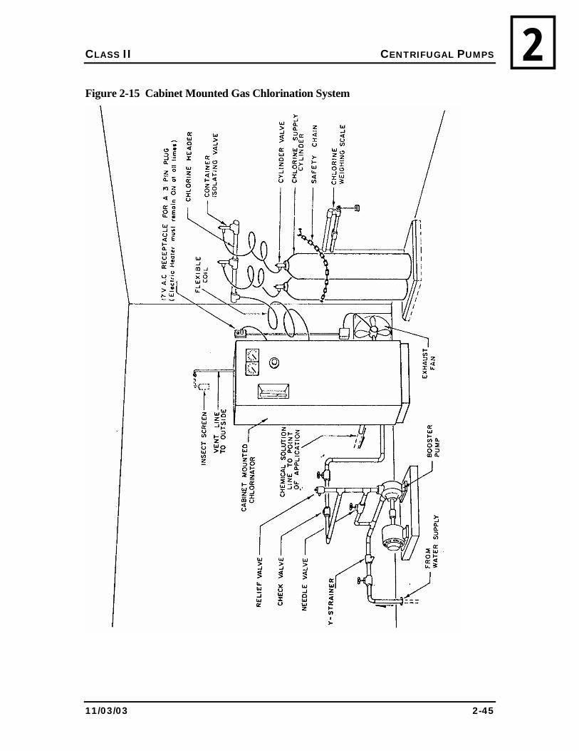
CLASS II CENTRIFUGAL PUMPS
11/03/03 2-45
2Figure 2-15 Cabinet Mounted Gas Chlorination System
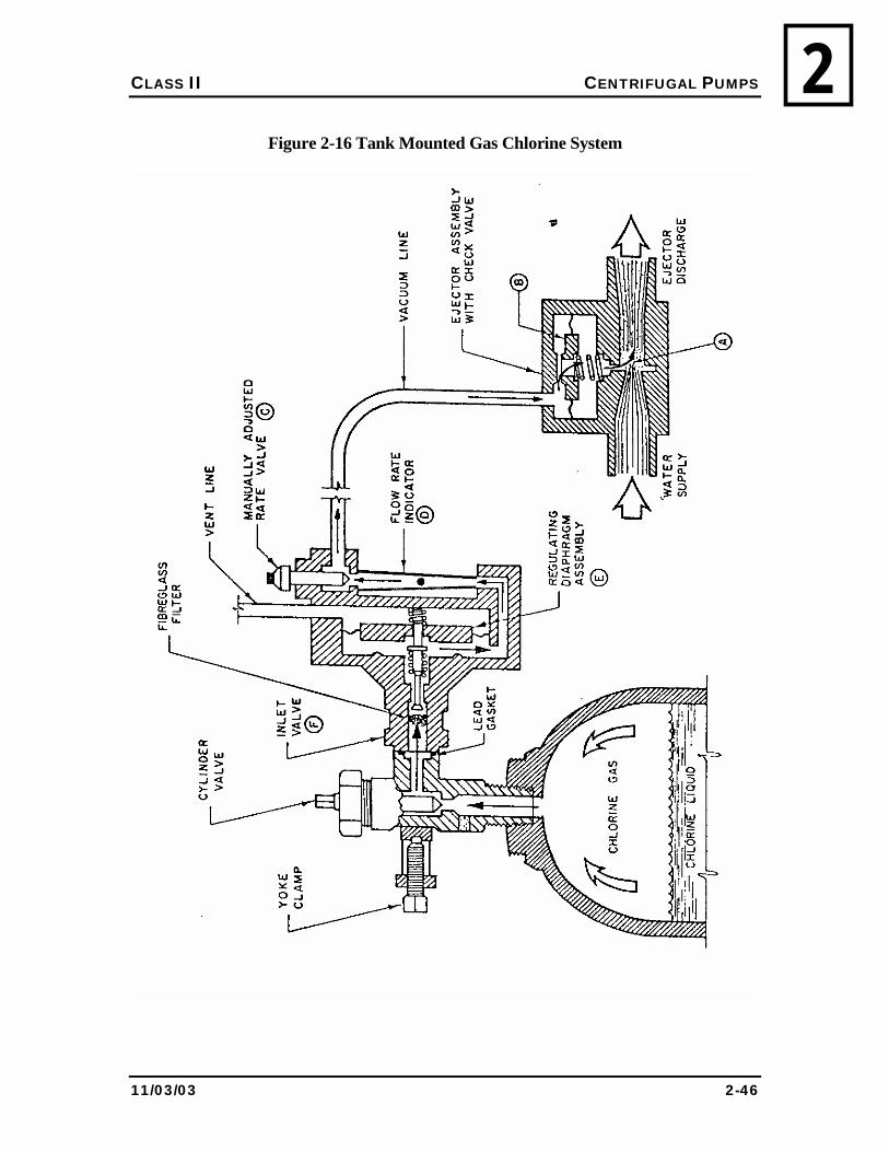
CLASS II CENTRIFUGAL PUMPS
11/03/03 2-46
2Figure 2-16 Tank Mounted Gas Chlorine System
CLASS II CENTRIFUGAL PUMPS
11/03/03 2-47
2For your safety
Chlorine gas is extremely dangerous.
Accidents can cause severe respiratory damage and even death.
Do not operate gas chlorination equipment unless you are properly trained.
Do not operate gas chlorination equipment without following all the prescribed safety precautions.
Never change gas chlorine tanks when you are alone.
Gas chlorination example
At 8:00 am the chlorine cylinder scale read 62.1 kg and the water meter read 17,256,167 litres.
At 8:00 am the next day the chlorine scale read 53.6 kg and the water meter read 18,890,528 litres.
What was the average dosage rate during the period?
Dosage = weight of 100% Cl2 (mg/l) (2.15) volume of water treated
= (62.1 - 53.6) kg * 1,000,000 mg/kg 18,890,528 - 17,256,167 l
= 8.5 kg * 1,000,000 mg/kg 1,634,361 l
= 5.2 mg/l
CLASS II CENTRIFUGAL PUMPS
11/03/03 2-48
22.12.5 ADDITIONAL METHODS OF DISINFECTION
Ozone (O3) is made by passing a high-voltage electrical current through air or oxygen. Ozone is used extensively in Europe. It can be very costly, especially on smaller scale plants.
Chloramines are formed when chlorine and ammonia are combined. While chloramines are somewhat less effective than free chlorine, they tend to last longer. For this reason they are sometimes used in long pipelines to reduce the potential for bacterial re-growth (formation of bacteria after the water treatment process) within the pipelines.
Chlorine dioxide is a more powerful oxidant than free chlorine. It has some application in the control of taste and odour, and is an excellent disinfectant. However, it must be generated on-site, which is inconvenient, complicated, and expensive.
Ultraviolet light is not generally used in public water supplies in the NWT. There are some mines and camps in the North where ultraviolet light is used; however, this application requires special approval. Ultraviolet light provides no residual and its effectiveness is severely affected by turbidity and colour. Ultraviolet light systems are finding more use in southern applications to provide pre-filter disinfection.
2.13 SCALING AND CORROSION CONTROL
2.13.1 INTRODUCTION
One of the many objectives of water treatment is the production of non-corrosive water. Corrosion of iron and steel distribution systems causes millions of dollars of damage every year in Canada. Aluminium and copper can be subjected to corrosion depending on water quality and other conditions.
Scaling of water lines increases friction and distribution costs and reduces pipe flow significantly. Consumer complaints increase with increased corrosion as �red water�, taste problems, and household plumbing can be affected.
There are two types of corrosion mechanisms. One is called chemical corrosion, where an electrical current between the metal and the water occurs as a result of chemical reactions.
The second mechanism is a result of corrosion enhancing bacteria, whose life processes use iron or sulphate. These bacteria are not in themselves harmful. However, as they live and grow, they produce a layer of slime in the system. The slime can, however, shield pathogenic organisms.
The slime will increase in size until the flowing water pulls them from the pipe walls. In water tanks, where turbulence can be low, these slimes can grow extensively. You can expect complaints when these slimes come out of a consumer�s water tap.
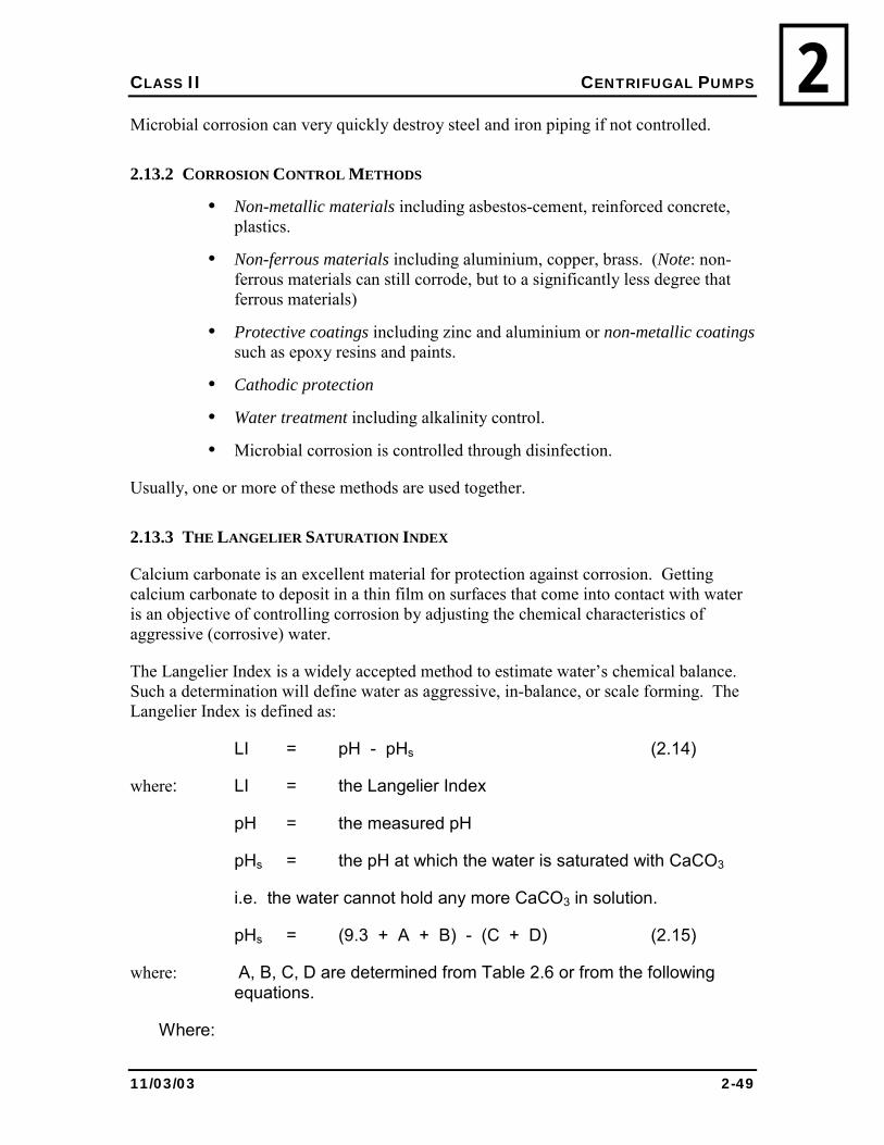
CLASS II CENTRIFUGAL PUMPS
11/03/03 2-49
2Microbial corrosion can very quickly destroy steel and iron piping if not controlled.
2.13.2 CORROSION CONTROL METHODS
• Non-metallic materials including asbestos-cement, reinforced concrete, plastics.
• Non-ferrous materials including aluminium, copper, brass. (Note: non-ferrous materials can still corrode, but to a significantly less degree that ferrous materials)
• Protective coatings including zinc and aluminium or non-metallic coatings such as epoxy resins and paints.
• Cathodic protection
• Water treatment including alkalinity control.
• Microbial corrosion is controlled through disinfection.
Usually, one or more of these methods are used together.
2.13.3 THE LANGELIER SATURATION INDEX
Calcium carbonate is an excellent material for protection against corrosion. Getting calcium carbonate to deposit in a thin film on surfaces that come into contact with water is an objective of controlling corrosion by adjusting the chemical characteristics of aggressive (corrosive) water.
The Langelier Index is a widely accepted method to estimate water�s chemical balance. Such a determination will define water as aggressive, in-balance, or scale forming. The Langelier Index is defined as:
LI = pH - pHs (2.14)
where: LI = the Langelier Index
pH = the measured pH
pHs = the pH at which the water is saturated with CaCO3
i.e. the water cannot hold any more CaCO3 in solution.
pHs = (9.3 + A + B) - (C + D) (2.15)
where: A, B, C, D are determined from Table 2.6 or from the following equations.
Where:
CLASS II CENTRIFUGAL PUMPS
11/03/03 2-50
2 A = (Log10 [TDS] - 1) / 10 (2.16)
B = -13.12 x Log10 (oC + 273) + 34.55 (2.17)
C = Log10 [Ca2+ as CaCO3] - 0.4 (2.18)
D = Log10 [alkalinity as CaCO3] (2.19)
Or A, B, C, and D can be determined from the look-up table (Table 2.6)
Interpreting Results
if: LI = 0, then the water is in chemical balance.
LI is negative, the water will probably be corrosive
LI is positive, the water will probably be scale-forming
The more positive or negative the LI is, the more extreme the scale-forming or corrosive tendencies will be. Therefore, it is desirable to maintain the LI slightly positive. A thin film of CaCO3 will be deposited without excessive scale build up.
Example 1
Calculate the LI for water with the following characteristics:
Total solids = 320 mg/l
Temperature = 1
Calcium Hardness = 160
Alkalinity = 194
pH = 7.6
Calculating Example 1
Total solids = 320 mg/l A = 0.152
Temperature = 1 B = 2.57
Calcium Hardness = 160 C = 1.81
Alkalinity = 194 D = 2.28
pH = 7.6
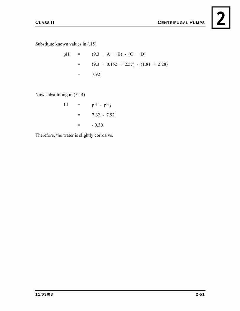
CLASS II CENTRIFUGAL PUMPS
11/03/03 2-51
2
Substitute known values in (.15)
pHs = (9.3 + A + B) - (C + D)
= (9.3 + 0.152 + 2.57) - (1.81 + 2.28)
= 7.92
Now substituting in (5.14)
LI = pH - pHs
= 7.62 - 7.92
= - 0.30
Therefore, the water is slightly corrosive.
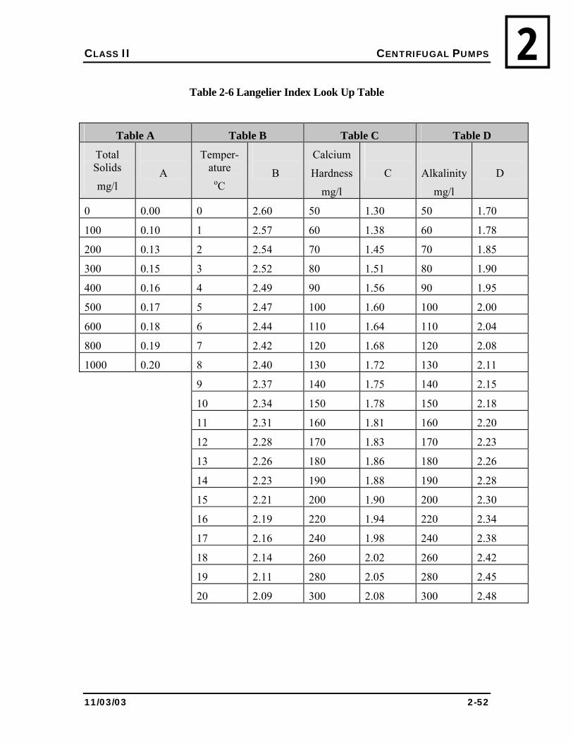
CLASS II CENTRIFUGAL PUMPS
11/03/03 2-52
2Table 2-6 Langelier Index Look Up Table
Table A Table B Table C Table D
Total Solids
mg/l
A
Temper-ature
oC
B
Calcium
Hardness
mg/l
C
Alkalinity
mg/l
D
0 0.00 0 2.60 50 1.30 50 1.70
100 0.10 1 2.57 60 1.38 60 1.78
200 0.13 2 2.54 70 1.45 70 1.85
300 0.15 3 2.52 80 1.51 80 1.90
400 0.16 4 2.49 90 1.56 90 1.95
500 0.17 5 2.47 100 1.60 100 2.00
600 0.18 6 2.44 110 1.64 110 2.04
800 0.19 7 2.42 120 1.68 120 2.08
1000 0.20 8 2.40 130 1.72 130 2.11
9 2.37 140 1.75 140 2.15
10 2.34 150 1.78 150 2.18
11 2.31 160 1.81 160 2.20
12 2.28 170 1.83 170 2.23
13 2.26 180 1.86 180 2.26
14 2.23 190 1.88 190 2.28
15 2.21 200 1.90 200 2.30
16 2.19 220 1.94 220 2.34
17 2.16 240 1.98 240 2.38
18 2.14 260 2.02 260 2.42
19 2.11 280 2.05 280 2.45
20 2.09 300 2.08 300 2.48
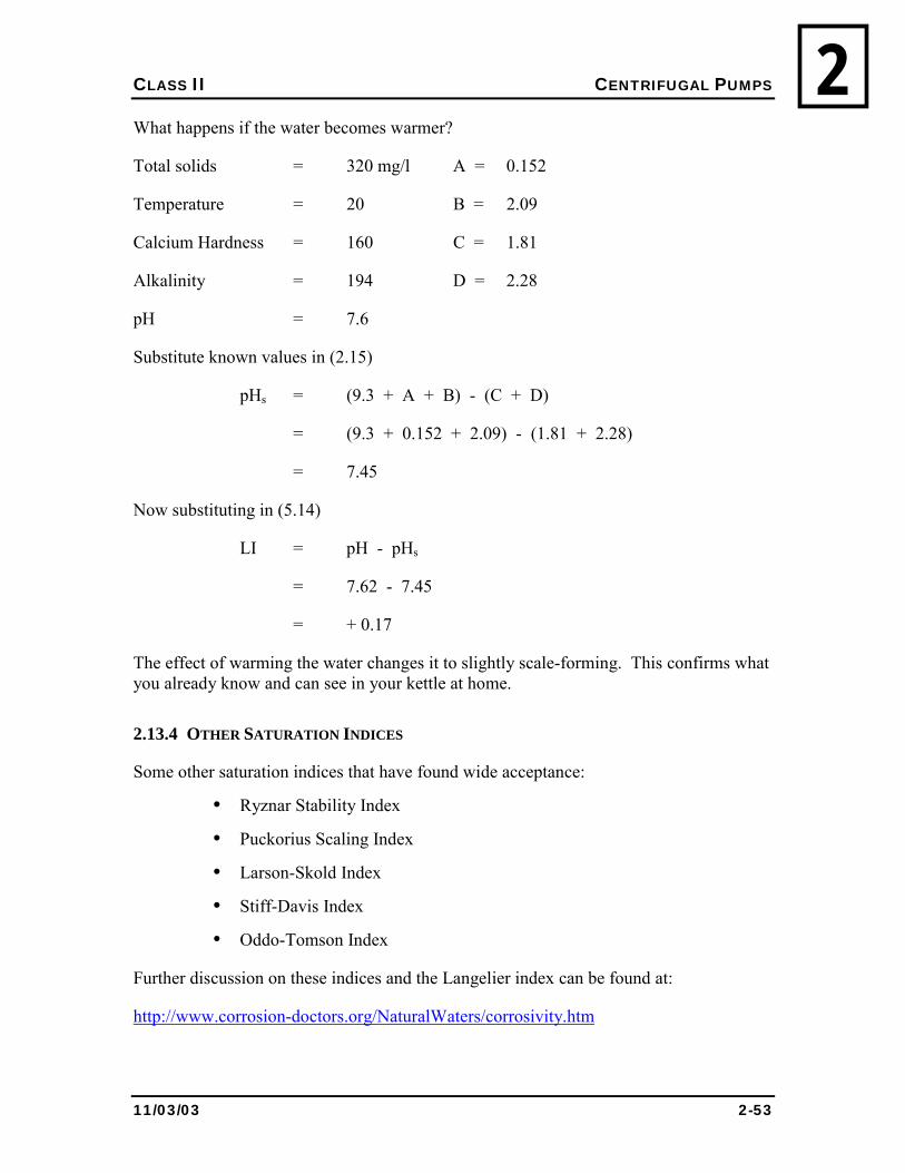
CLASS II CENTRIFUGAL PUMPS
11/03/03 2-53
2What happens if the water becomes warmer?
Total solids = 320 mg/l A = 0.152
Temperature = 20 B = 2.09
Calcium Hardness = 160 C = 1.81
Alkalinity = 194 D = 2.28
pH = 7.6
Substitute known values in (2.15)
pHs = (9.3 + A + B) - (C + D)
= (9.3 + 0.152 + 2.09) - (1.81 + 2.28)
= 7.45
Now substituting in (5.14)
LI = pH - pHs
= 7.62 - 7.45
= + 0.17
The effect of warming the water changes it to slightly scale-forming. This confirms what you already know and can see in your kettle at home.
2.13.4 OTHER SATURATION INDICES
Some other saturation indices that have found wide acceptance:
• Ryznar Stability Index
• Puckorius Scaling Index
• Larson-Skold Index
• Stiff-Davis Index
• Oddo-Tomson Index
Further discussion on these indices and the Langelier index can be found at:
http://www.corrosion-doctors.org/NaturalWaters/corrosivity.htm
CLASS II CENTRIFUGAL PUMPS
11/03/03 2-54
22.13.5 TROUBLESHOOTING RED WATER PROBLEMS
Step 1. Ensure the iron and manganese treatment processes are working properly.
Step 2. If the red water complaint is from a consumer who is not on a piped system, the problem may be cross contamination. An investigation should begin immediately.
Step 3. Investigate the distribution system.
Corrosive waters or iron bacteria may cause red water or dirty water in the distribution system. Corrosive water attacks iron pipes and metal service lines, picks up iron, and causes red water.
The growth of iron bacteria inside water systems causes troublesome and difficult red water problems. Slime growths can be controlled by maintaining a free available chlorine residual throughout the distribution system. If the bacteria have been flourishing in the system, or a water tank, a free available chlorine residual may be difficult to maintain.
Remember that when consumers complain about chlorine or swimming pool tasting water, the solution is often to add more chlorine to get past the break point.
Distribution systems should be flushed regularly, not only to remove iron bacteria, but also to remove sediments and insoluble precipitates from the system.
In piped systems, a common practice is to open a hydrant at the extreme end of the system to make sure the sediment moves in the right direction, then begin opening and closing valves at the beginning of the system, moving toward the final open valve. In order to flush properly the system must be capable of flushing velocities above 2.5 m/s.
In trucked systems, it is common practice to routinely clean and chlorinate the truck tank, pump, and hose.
Water tanks in public buildings should be cleaned and flushed annually.
CLASS II CENTRIFUGAL PUMPS
11/03/03 2-55
22.14 REVIEW
2.14.1 Explain the rational method for determining runoff and calculate the estimated runoff on 100,000 m2 of frozen land if there is 10 centimetres of rain.
2.14.2 What is the purpose of coagulant aids?
2.14.3 How is pH decreased?
2.14.4 What are the problems that may occur if
• The flocculation period is too short?
• The flocculation period is too long?
• The intensity (speed) of mixing is too low?
• The intensity (speed) of mixing is too high?
CLASS II CENTRIFUGAL PUMPS
11/03/03 2-56
22.14.5 In practice, what is considered an operational guideline for residual aluminium
concentration in treated water?
2.14.6 What is �coning� and how does it effect collection and removal of sludge?
2.14.7 What methods can be used to remove bad taste and odour in water?
2.14.8 What causes red water and what can be done to correct the problem?
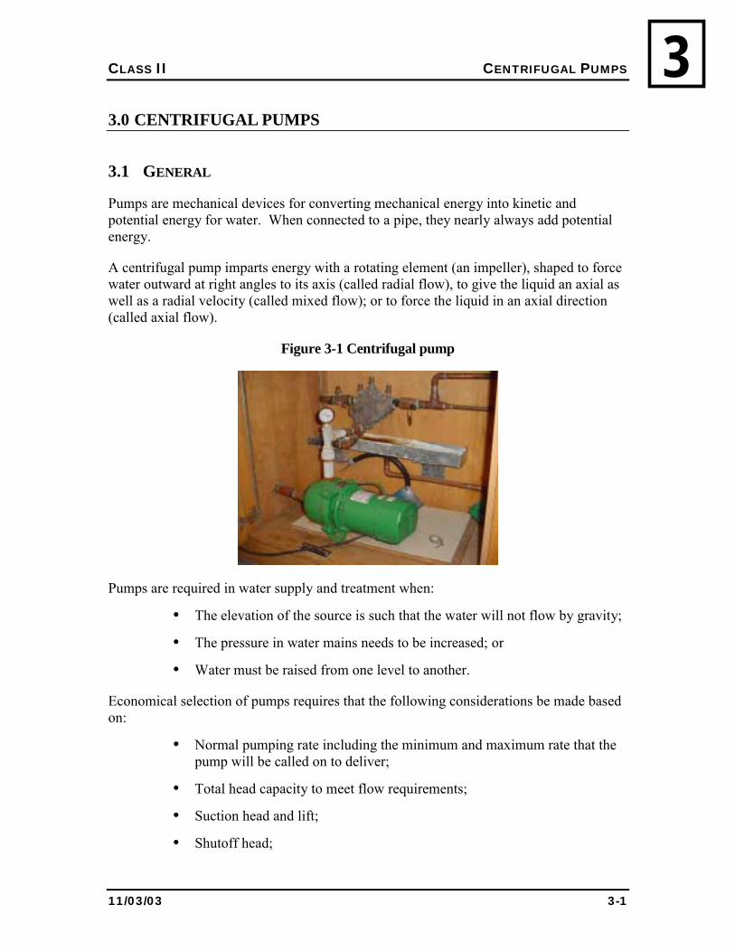
CLASS II CENTRIFUGAL PUMPS
11/03/03 3-1
33.0 CENTRIFUGAL PUMPS
3.1 GENERAL
Pumps are mechanical devices for converting mechanical energy into kinetic and potential energy for water. When connected to a pipe, they nearly always add potential energy.
A centrifugal pump imparts energy with a rotating element (an impeller), shaped to force water outward at right angles to its axis (called radial flow), to give the liquid an axial as well as a radial velocity (called mixed flow); or to force the liquid in an axial direction (called axial flow).
Figure 3-1 Centrifugal pump
Pumps are required in water supply and treatment when:
• The elevation of the source is such that the water will not flow by gravity;
• The pressure in water mains needs to be increased; or
• Water must be raised from one level to another.
Economical selection of pumps requires that the following considerations be made based on:
• Normal pumping rate including the minimum and maximum rate that the pump will be called on to deliver;
• Total head capacity to meet flow requirements;
• Suction head and lift;
• Shutoff head;
CLASS II CENTRIFUGAL PUMPS
11/03/03 3-2
3• Net Positive Suction Head required versus Net Positive Suction Head
available;
• Efficiency;
• Pump characteristics including, speed, power source, environmental and other special requirements; and
• The physical properties (temperature, chemical constituents, etc.) of the liquid to be pumped.
3.2 OPERATION UNDER SUCTION LIFT CONDITIONS
3.2.1 NET POSITIVE SUCTION HEAD
When water is thrown from an impeller, a partial vacuum is created at the eye of the impeller. Atmospheric pressure forces more water into the eye of the impeller. This is called, �suction lift�. Note that the pump does not �suck� water; instead the water is pushed by atmospheric pressure into a zone of lower pressure at the eye of the impeller.
When a pump is in a suction lift position, the only energy available to push water into the pump is the pressure of the atmosphere. Several factors combine to reduce the effect of atmospheric pressure. These factors combine into what is called, �net positive suction head� (NPSH). These factors are:
Vapour pressure - All liquids possess a tendency to vaporise, that is, to change from the liquid to the gaseous phase. Molecules are constantly moving between the liquid and vapour phases. The vapour above the liquid exerts its own pressure. This is called �vapour pressure�. An increase in temperature or a decrease in pressure will increase the rate of vaporisation. Boiling occurs when the external pressure is equal to, or less than, the vapour pressure of the liquid. If the space above the liquid is small, then the number of molecules escaping will equal the number returning. If the space is large, then equilibrium will not be reached and the liquid continues to vaporise. This is also called, �evaporation�.
Suction lift - Suction lift is the distance between the surface of the liquid and the eye of the impeller (centre line of the pump).
Friction head loss - Friction head loss is the head required to overcome friction in the suction pipe and fittings. The relationship between these factors as it relates to NPSH is as follows:
NPSH = Suction Lift � Vapour Pressure � Frictional Head Loss
CLASS II CENTRIFUGAL PUMPS
11/03/03 3-3
3Net Positive Suction Head (NPSH) is a statement of the minimum suction conditions required to prevent cavitation in a pump. A negative value for the NPSH would indicate cavitation would occur in the pump. The required NPSH for any given pump is determined in tests conducted by the manufacturer.
Not enough NPSH causes cavitation in the pump and the pump sounds like it is �pumping rocks�. If this occurs, slowly close the discharge valve. If the pump starts to smooth out, there is not enough NPSH. It is not always possible to hear cavitation as it is frequently masked by machinery noises. If you can hear it, damage is being done. If you can�t hear it, there may still be damage. It is required that the available NPSH exceed the required NPSH as stated by the manufacturer.
The factor that primarily affects the available NPSH is the suction lift. Under most conditions the maximum suction lift rarely exceeds 6 metres. This value is further reduced with increasing temperature and the distance above sea level. In some cases, reduced atmospheric pressure may contribute to cavitation problems.
3.2.2 OPERATION UNDER SUCTION HEAD CONDITIONS
When the eye of the impeller is below the level of a water source, the pump is said to have a suction head (also called a flooded impeller). Such conditions are typical of a submerged pump. Under these conditions, if the head above the pump is equal to or greater than the NPSH specified by the manufacturer, it can be assumed that the available NPSH is adequate.
3.3 TOTAL DYNAMIC HEAD
The energy required to lift water from one level to another is related to the head on the pump. Illustrated in Figure 3.2, this lift is called, �total dynamic head�, and is the sum of the static head, the velocity head, and the friction head.
3.4 PUMP CURVES
Every pump manufacturer provides characteristic curves for each pump. Such curves are used to select a pump for a given duty. They are also used to determine the effects of changes in: impeller diameter, pump speed, suction lift, power, and efficiency.
The curves are developed from actual measurements (empirically) and are more accurate than theoretical calculations. Figure 3.2 shows a typical pump curve. Note how the vertices axes can show more than one piece of data about the pump. In fact, many pump curves will include more than one model on the same curve.
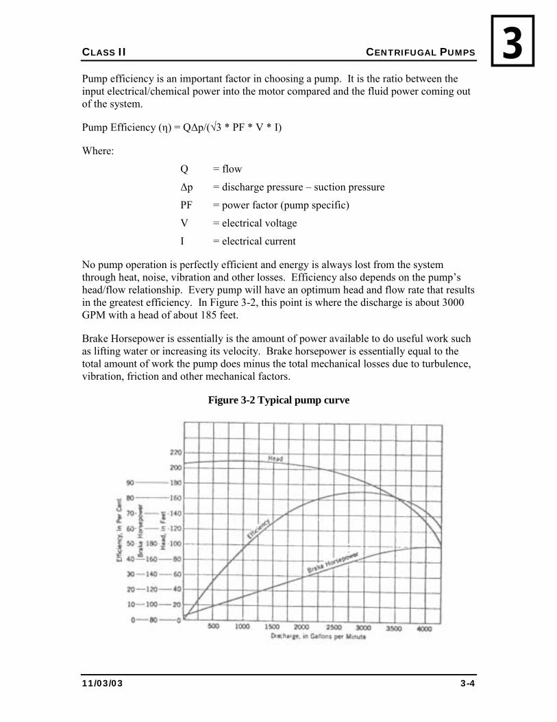
CLASS II CENTRIFUGAL PUMPS
11/03/03 3-4
3Pump efficiency is an important factor in choosing a pump. It is the ratio between the input electrical/chemical power into the motor compared and the fluid power coming out of the system.
Pump Efficiency (η) = Q∆p/(√3 * PF * V * I)
Where:
Q = flow
∆p = discharge pressure � suction pressure
PF = power factor (pump specific)
V = electrical voltage
I = electrical current
No pump operation is perfectly efficient and energy is always lost from the system through heat, noise, vibration and other losses. Efficiency also depends on the pump�s head/flow relationship. Every pump will have an optimum head and flow rate that results in the greatest efficiency. In Figure 3-2, this point is where the discharge is about 3000 GPM with a head of about 185 feet.
Brake Horsepower is essentially is the amount of power available to do useful work such as lifting water or increasing its velocity. Brake horsepower is essentially equal to the total amount of work the pump does minus the total mechanical losses due to turbulence, vibration, friction and other mechanical factors.
Figure 3-2 Typical pump curve
CLASS II CENTRIFUGAL PUMPS
11/03/03 3-5
33.5 MULTIPLE PUMP OPERATION
Most centrifugal pump installations have more than one pumping unit. The purposes are many:
• Standby pumping capacity;
• Operation over a wide range of flows; and
• Too great a head for one pump.
3.5.1 PARALLEL OPERATION
Most pumping systems are required to operate over a wide range of flows. It can be done efficiently with two or three pumps in parallel. Pumps are operated on demand.
Figure 3.3 shows two identical pumps in parallel. Curve AB shows one pump operating alone, while curve AC shows both pumps operating together. Note that curve AC is developed by adding the capacities of each pump at a given head. In this installation, one pump would be used in the flow range from 0 to the flow at point D. Both pumps would be used to provide flows between point D and point E.
Figure 3.4 shows two different pumps in parallel. The head for pump 1 is represented by the curve AB and the head for pump 2 is represented by CD. The curve AEF represents parallel operation. If the flow were to decrease to point E or less, pump 1 would be operating at the shutoff condition. This is the same as having the discharge valve completely closed. If the condition persisted, heat would be generated and the pump damaged.
Different pumps are often found in systems that have been expanded over a number of years. In some cases, the cost of replacing a pump with one more suitable can be justified. It is sometimes possible to modify the larger pump by changing the speed or the impeller size so the two are more evenly matched.
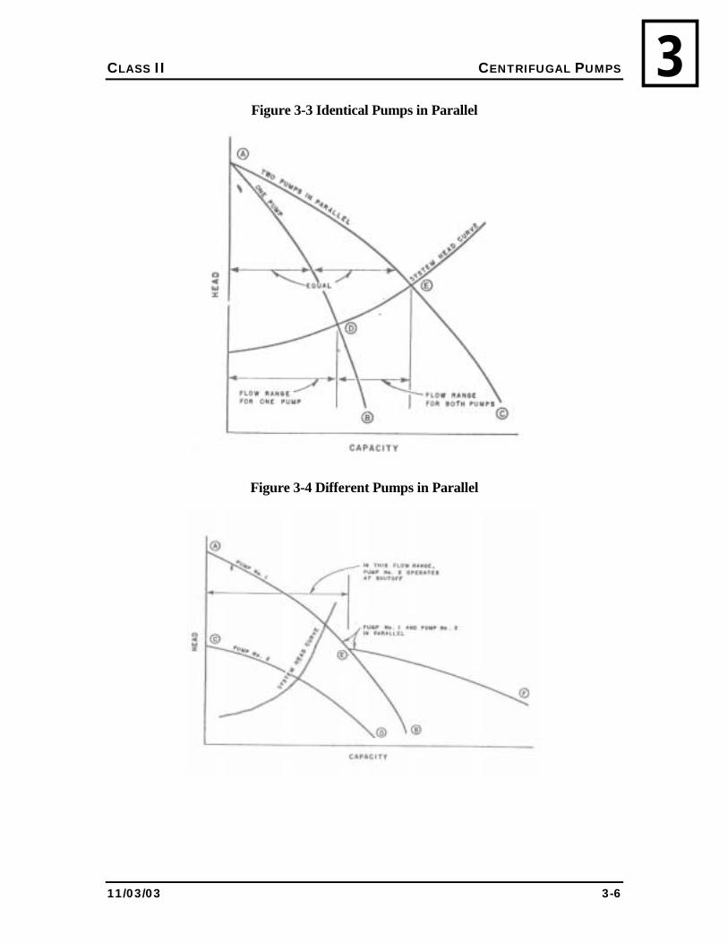
CLASS II CENTRIFUGAL PUMPS
11/03/03 3-6
3Figure 3-3 Identical Pumps in Parallel
Figure 3-4 Different Pumps in Parallel
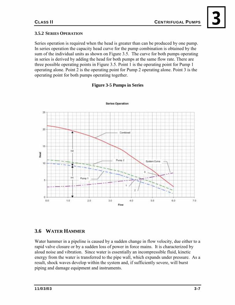
CLASS II CENTRIFUGAL PUMPS
11/03/03 3-7
33.5.2 SERIES OPERATION
Series operation is required when the head is greater than can be produced by one pump. In series operation the capacity head curve for the pump combination is obtained by the sum of the individual units as shown on Figure 3.5. The curve for both pumps operating in series is derived by adding the head for both pumps at the same flow rate. There are three possible operating points in Figure 3.5. Point 1 is the operating point for Pump 1 operating alone. Point 2 is the operating point for Pump 2 operating alone. Point 3 is the operating point for both pumps operating together.
Figure 3-5 Pumps in Series
3.6 WATER HAMMER
Water hammer in a pipeline is caused by a sudden change in flow velocity, due either to a rapid valve closure or by a sudden loss of power in force mains. It is characterized by aloud noise and vibration. Since water is essentially an incompressible fluid, kinetic energy from the water is transferred to the pipe wall, which expands under pressure. As a result, shock waves develop within the system and, if sufficiently severe, will burst piping and damage equipment and instruments.
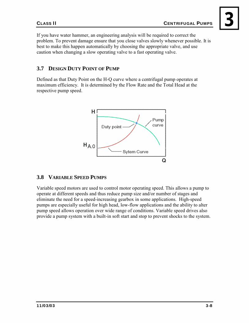
CLASS II CENTRIFUGAL PUMPS
11/03/03 3-8
3If you have water hammer, an engineering analysis will be required to correct the problem. To prevent damage ensure that you close valves slowly whenever possible. It is best to make this happen automatically by choosing the appropriate valve, and use caution when changing a slow operating valve to a fast operating valve.
3.7 DESIGN DUTY POINT OF PUMP
Defined as that Duty Point on the H-Q curve where a centrifugal pump operates at maximum efficiency. It is determined by the Flow Rate and the Total Head at the respective pump speed.
3.8 VARIABLE SPEED PUMPS
Variable speed motors are used to control motor operating speed. This allows a pump to operate at different speeds and thus reduce pump size and/or number of stages and eliminate the need for a speed-increasing gearbox in some applications. High-speed pumps are especially useful for high head, low-flow applications and the ability to alter pump speed allows operation over wide range of conditions. Variable speed drives also provide a pump system with a built-in soft start and stop to prevent shocks to the system.
CLASS II CENTRIFUGAL PUMPS
11/03/03 3-9
33.9 REVIEW
1. When are pumps required in water supply and treatment?
2. What information does a pump curve provide?
3. When is it efficient to have two or more pumps in parallel?
4. When is it efficient to have two or more pumps in series?
5. What is water hammer and how can you prevent it?
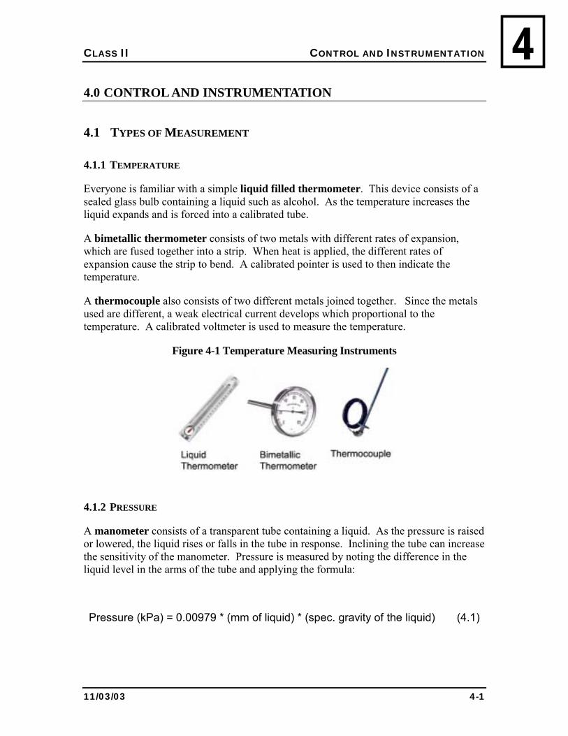
CLASS II CONTROL AND INSTRUMENTATION
11/03/03 4-1
44.0 CONTROL AND INSTRUMENTATION
4.1 TYPES OF MEASUREMENT
4.1.1 TEMPERATURE
Everyone is familiar with a simple liquid filled thermometer. This device consists of a sealed glass bulb containing a liquid such as alcohol. As the temperature increases the liquid expands and is forced into a calibrated tube.
A bimetallic thermometer consists of two metals with different rates of expansion, which are fused together into a strip. When heat is applied, the different rates of expansion cause the strip to bend. A calibrated pointer is used to then indicate the temperature.
A thermocouple also consists of two different metals joined together. Since the metals used are different, a weak electrical current develops which proportional to the temperature. A calibrated voltmeter is used to measure the temperature.
Figure 4-1 Temperature Measuring Instruments
4.1.2 PRESSURE
A manometer consists of a transparent tube containing a liquid. As the pressure is raised or lowered, the liquid rises or falls in the tube in response. Inclining the tube can increase the sensitivity of the manometer. Pressure is measured by noting the difference in the liquid level in the arms of the tube and applying the formula:
Pressure (kPa) = 0.00979 * (mm of liquid) * (spec. gravity of the liquid) (4.1)
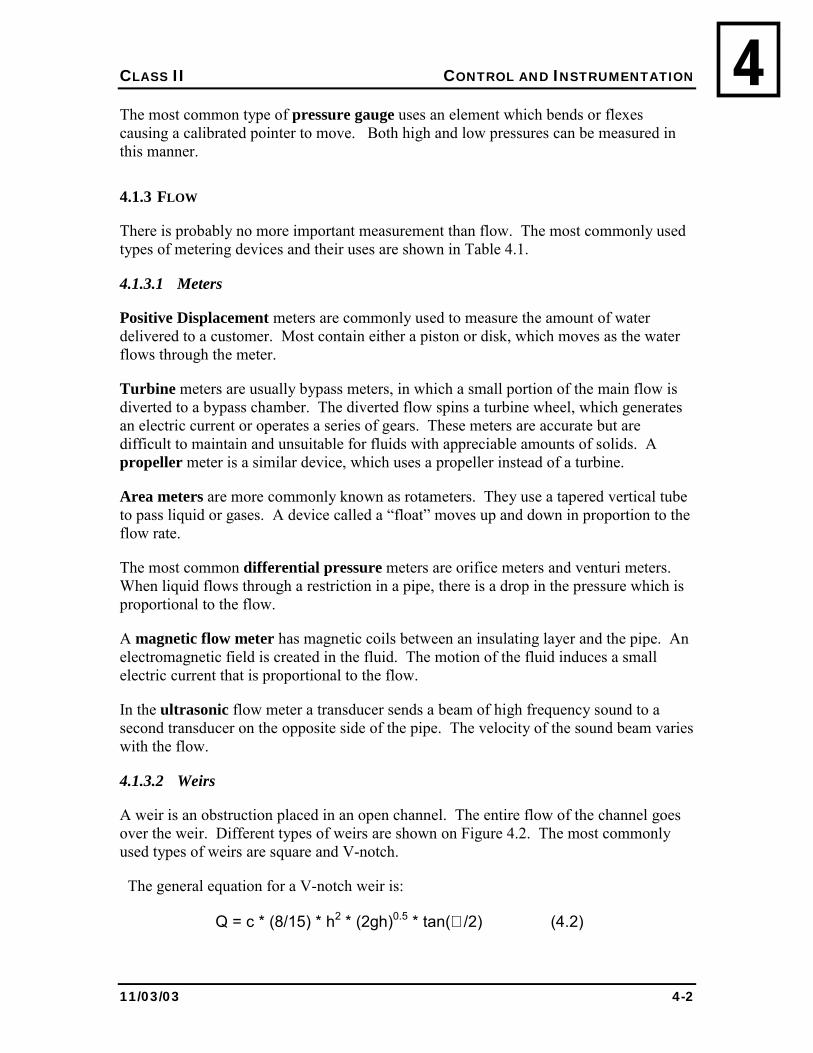
CLASS II CONTROL AND INSTRUMENTATION
11/03/03 4-2
4The most common type of pressure gauge uses an element which bends or flexes causing a calibrated pointer to move. Both high and low pressures can be measured in this manner.
4.1.3 FLOW
There is probably no more important measurement than flow. The most commonly used types of metering devices and their uses are shown in Table 4.1.
4.1.3.1 Meters
Positive Displacement meters are commonly used to measure the amount of water delivered to a customer. Most contain either a piston or disk, which moves as the water flows through the meter.
Turbine meters are usually bypass meters, in which a small portion of the main flow is diverted to a bypass chamber. The diverted flow spins a turbine wheel, which generates an electric current or operates a series of gears. These meters are accurate but are difficult to maintain and unsuitable for fluids with appreciable amounts of solids. A propeller meter is a similar device, which uses a propeller instead of a turbine.
Area meters are more commonly known as rotameters. They use a tapered vertical tube to pass liquid or gases. A device called a �float� moves up and down in proportion to the flow rate.
The most common differential pressure meters are orifice meters and venturi meters. When liquid flows through a restriction in a pipe, there is a drop in the pressure which is proportional to the flow.
A magnetic flow meter has magnetic coils between an insulating layer and the pipe. An electromagnetic field is created in the fluid. The motion of the fluid induces a small electric current that is proportional to the flow.
In the ultrasonic flow meter a transducer sends a beam of high frequency sound to a second transducer on the opposite side of the pipe. The velocity of the sound beam varies with the flow.
4.1.3.2 Weirs
A weir is an obstruction placed in an open channel. The entire flow of the channel goes over the weir. Different types of weirs are shown on Figure 4.2. The most commonly used types of weirs are square and V-notch.
The general equation for a V-notch weir is:
Q = c * (8/15) * h2 * (2gh)0.5 * tan(∅ /2) (4.2)
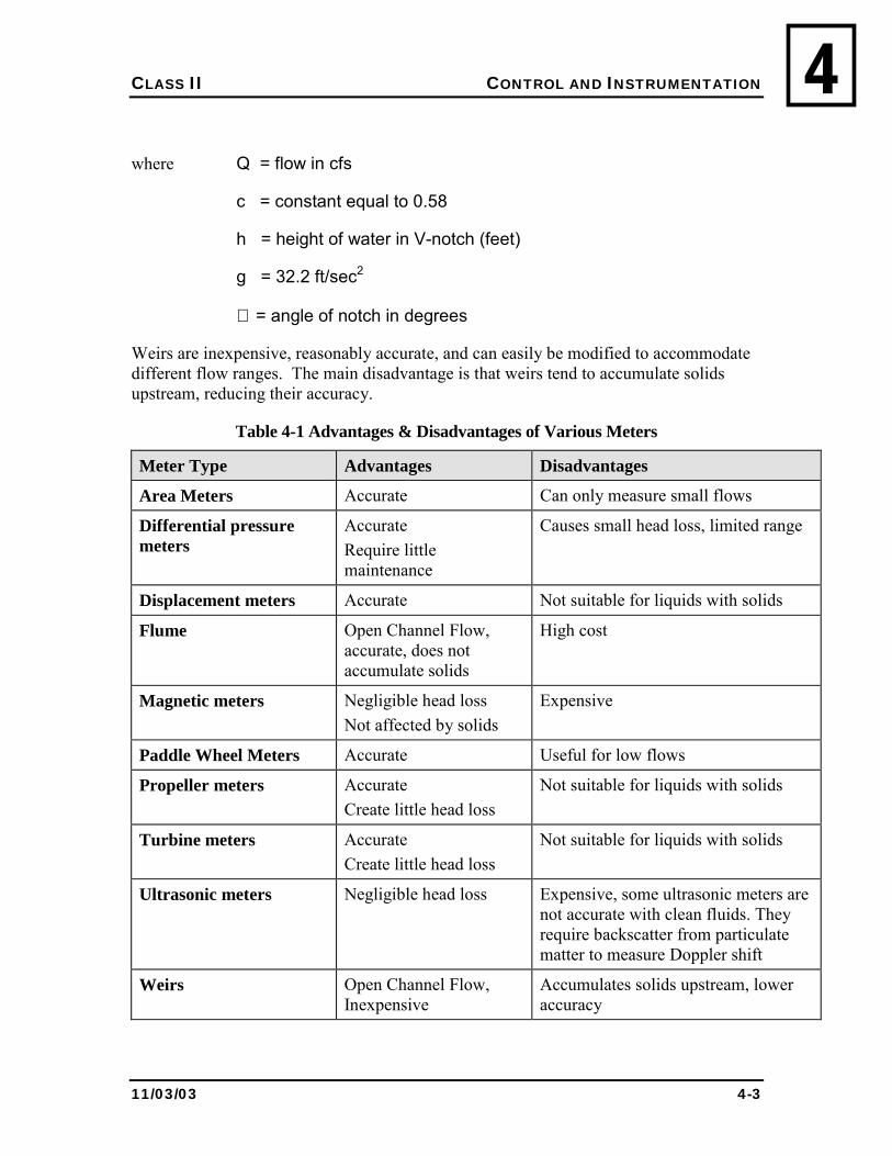
CLASS II CONTROL AND INSTRUMENTATION
11/03/03 4-3
4
where Q = flow in cfs
c = constant equal to 0.58
h = height of water in V-notch (feet)
g = 32.2 ft/sec2
∅ = angle of notch in degrees
Weirs are inexpensive, reasonably accurate, and can easily be modified to accommodate different flow ranges. The main disadvantage is that weirs tend to accumulate solids upstream, reducing their accuracy.
Table 4-1 Advantages & Disadvantages of Various Meters
Meter Type Advantages Disadvantages
Area Meters Accurate Can only measure small flows
Differential pressure meters
Accurate Require little maintenance
Causes small head loss, limited range
Displacement meters Accurate Not suitable for liquids with solids
Flume Open Channel Flow, accurate, does not accumulate solids
High cost
Magnetic meters Negligible head loss Not affected by solids
Expensive
Paddle Wheel Meters Accurate Useful for low flows
Propeller meters Accurate Create little head loss
Not suitable for liquids with solids
Turbine meters Accurate Create little head loss
Not suitable for liquids with solids
Ultrasonic meters Negligible head loss
Expensive, some ultrasonic meters are not accurate with clean fluids. They require backscatter from particulate matter to measure Doppler shift
Weirs Open Channel Flow, Inexpensive
Accumulates solids upstream, lower accuracy
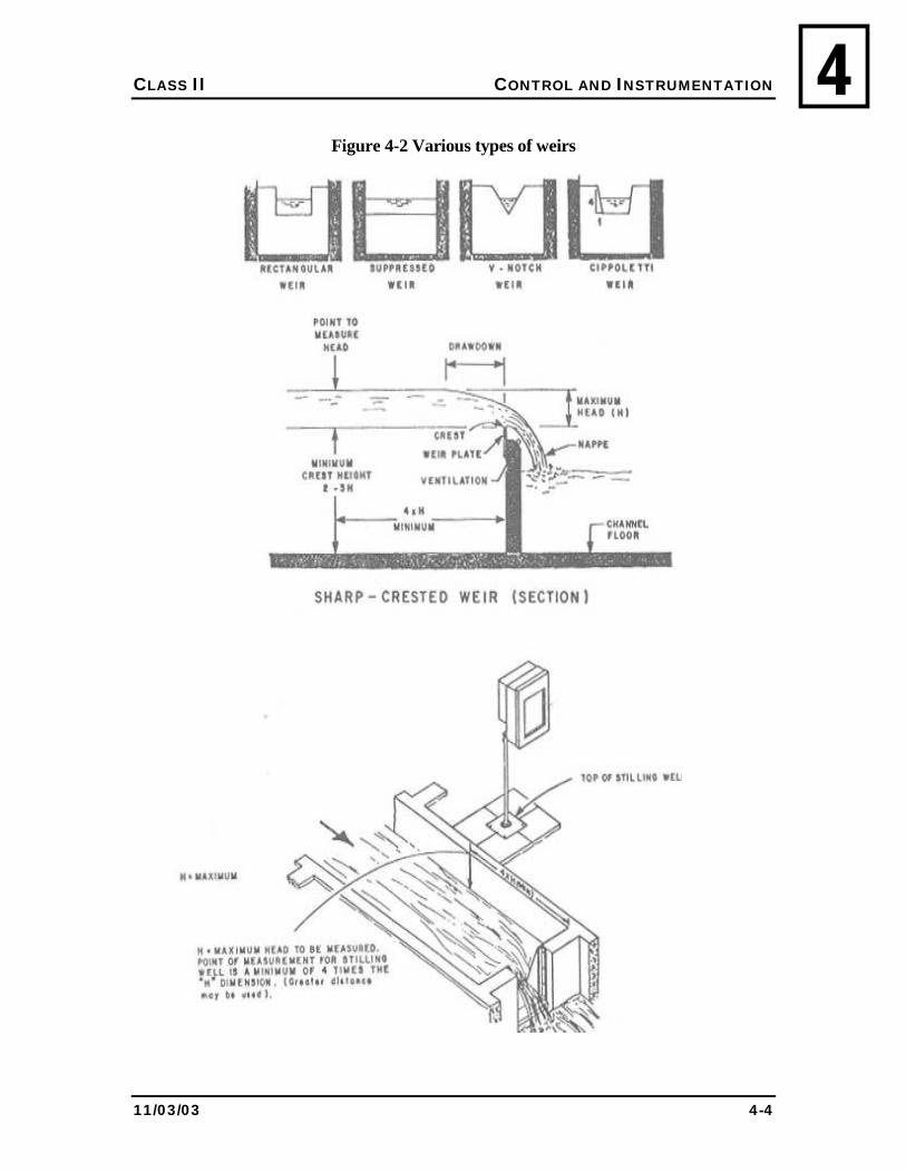
CLASS II CONTROL AND INSTRUMENTATION
11/03/03 4-4
4Figure 4-2 Various types of weirs
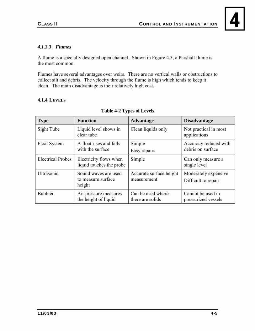
CLASS II CONTROL AND INSTRUMENTATION
11/03/03 4-5
4
4.1.3.3 Flumes
A flume is a specially designed open channel. Shown in Figure 4.3, a Parshall flume is the most common.
Flumes have several advantages over weirs. There are no vertical walls or obstructions to collect silt and debris. The velocity through the flume is high which tends to keep it clean. The main disadvantage is their relatively high cost.
4.1.4 LEVELS
Table 4-2 Types of Levels
Type Function Advantage Disadvantage
Sight Tube Liquid level shows in clear tube
Clean liquids only Not practical in most applications
Float System A float rises and falls with the surface
Simple Easy repairs
Accuracy reduced with debris on surface
Electrical Probes Electricity flows when liquid touches the probe
Simple Can only measure a single level
Ultrasonic Sound waves are used to measure surface height
Accurate surface height measurement
Moderately expensive Difficult to repair
Bubbler Air pressure measures the height of liquid
Can be used where there are solids
Cannot be used in pressurized vessels
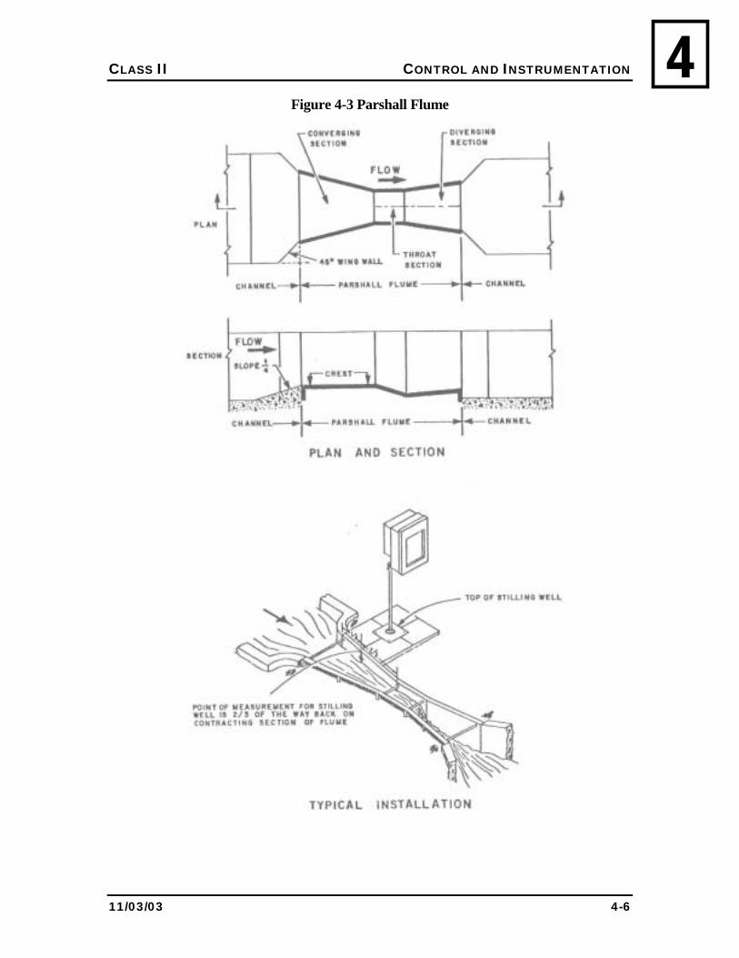
CLASS II CONTROL AND INSTRUMENTATION
11/03/03 4-6
4Figure 4-3 Parshall Flume
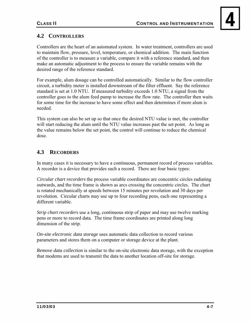
CLASS II CONTROL AND INSTRUMENTATION
11/03/03 4-7
44.2 CONTROLLERS
Controllers are the heart of an automated system. In water treatment, controllers are used to maintain flow, pressure, level, temperature, or chemical addition. The main function of the controller is to measure a variable, compare it with a reference standard, and then make an automatic adjustment to the process to ensure the variable remains with the desired range of the reference standard.
For example, alum dosage can be controlled automatically. Similar to the flow controller circuit, a turbidity meter is installed downstream of the filter effluent. Say the reference standard is set at 1.0 NTU. If measured turbidity exceeds 1.0 NTU, a signal from the controller goes to the alum feed pump to increase the flow rate. The controller then waits for some time for the increase to have some effect and then determines if more alum is needed.
This system can also be set up so that once the desired NTU value is met, the controller will start reducing the alum until the NTU value increases past the set point. As long as the value remains below the set point, the control will continue to reduce the chemical dose.
4.3 RECORDERS
In many cases it is necessary to have a continuous, permanent record of process variables. A recorder is a device that provides such a record. There are four basic types:
Circular chart recorders the process variable coordinates are concentric circles radiating outwards, and the time frame is shown as arcs crossing the concentric circles. The chart is rotated mechanically at speeds between 15 minutes per revolution and 30 days per revolution. Circular charts may use up to four recording pens, each one representing a different variable.
Strip chart recorders use a long, continuous strip of paper and may use twelve marking pens or more to record data. The time frame coordinates are printed along long dimension of the strip.
On-site electronic data storage uses automatic data collection to record various parameters and stores them on a computer or storage device at the plant.
Remove data collection is similar to the on-site electronic data storage, with the exception that modems are used to transmit the data to another location off-site for storage.
CLASS II CONTROL AND INSTRUMENTATION
11/03/03 4-8
44.4 TOTALIZERS
Also known as integrators, these are devices that add and/or multiply two or more variables to give a different variable. For example, a flow totalizer multiplies the flow rate by time to give a running total of the volume, which has passed through the system.
4.5 OPERATION AND MAINTENANCE
The instruments in a treatment plant require regular inspection, adjustment, calibration, and maintenance. Operators must be able to recognize when instruments and controls are not functioning properly, and take command of the situation. This may involve anything from a simple adjustment to over-riding the equipment and operating manually.
Most modern instruments and control systems are complex and sophisticated. Unless the operator is properly trained, repair of these systems should be left to specialists. The cost of damage to a single critical instrument by unqualified tampering usually exceeds the cost of contracting maintenance work to a specialist.
Despite their apparent sophistication, most instruments and control systems are quite robust. Often, problems with accuracy may simply mean that the sensor is dirty. As with everything else, cleanliness should be your first priority.
Most operators are capable of, and should, carry out routine maintenance procedures such as general inspection, mechanical zero calibration, replacement of charts, cleaning of probes and sensors, lubrication, and other basic items. The manufacturer�s O&M manual will outline all the procedures you need to follow -- look it up before you pick up a tool.
Some important points to remember when working on any instrument or control system:
• Ensure that the recommended manuals, spare parts, and tools are available;
• If an instrument appears defective, refer to the manufacturer�s trouble shooting guide before you pick up a tool;
• Observe all safety procedures such as turning off the power, tagging and locking out the system;
• Ensure that co-workers are aware of your activities;
• Where possible, ensure that an alternative method of operation is implemented while the instrument is out of service; and
• Keep records of work done, cause and effect if known and anything else that you think is important.
CLASS II CONTROL AND INSTRUMENTATION
11/03/03 4-9
44.6 REVIEW
1. Describe the advantages and disadvantages of weirs.
2. What is the purpose of controllers?
3. Describe three types of meters.
4. What is the first priority with regard to maintenance of instrumentation?
5. What is the first thing to do when an instrument appears defective?
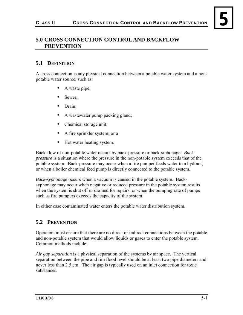
CLASS II CROSS-CONNECTION CONTROL AND BACKFLOW PREVENTION
11/03/03 5-1
55.0 CROSS CONNECTION CONTROL AND BACKFLOW
PREVENTION
5.1 DEFINITION
A cross connection is any physical connection between a potable water system and a non-potable water source, such as:
• A waste pipe;
• Sewer;
• Drain;
• A wastewater pump packing gland;
• Chemical storage unit;
• A fire sprinkler system; or a
• Hot water heating system.
Back-flow of non-potable water occurs by back-pressure or back-siphonage. Back-pressure is a situation where the pressure in the non-potable system exceeds that of the potable system. Back-pressure may occur when a fire pumper feeds water to a hydrant, or when a boiler chemical feed pump is directly connected to the potable system.
Back-syphonage occurs when a vacuum is caused in the potable system. Back-syphonage may occur when negative or reduced pressure in the potable system results when the system is shut off or drained for repairs, or when the pumping rate of pumps such as fire pumpers exceeds the capacity of the system.
In either case contaminated water enters the potable water distribution system.
5.2 PREVENTION
Operators must ensure that there are no direct or indirect connections between the potable and non-potable system that would allow liquids or gases to enter the potable system. Common methods include:
Air gap separation is a physical separation of the systems by air space. The vertical separation between the pipe and rim flood level should be at least two pipe diameters and never less than 2.5 cm. The air gap is typically used on an inlet connection for toxic substances.
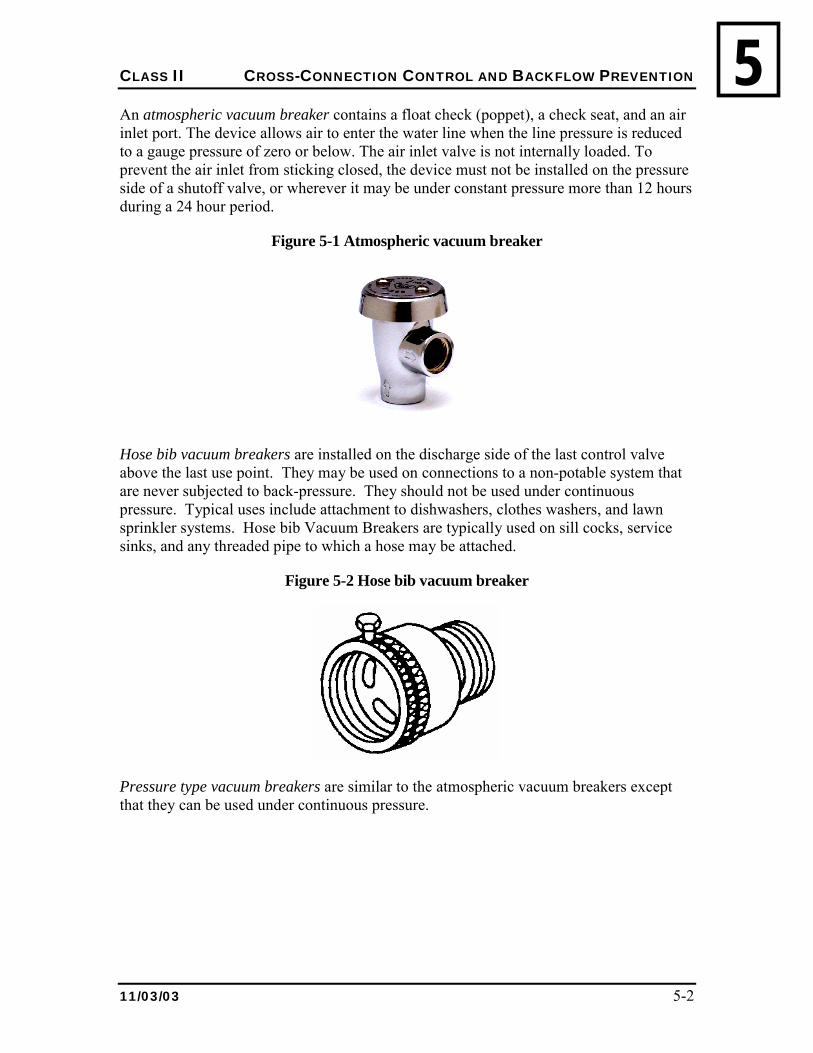
CLASS II CROSS-CONNECTION CONTROL AND BACKFLOW PREVENTION
11/03/03 5-2
5An atmospheric vacuum breaker contains a float check (poppet), a check seat, and an air inlet port. The device allows air to enter the water line when the line pressure is reduced to a gauge pressure of zero or below. The air inlet valve is not internally loaded. To prevent the air inlet from sticking closed, the device must not be installed on the pressure side of a shutoff valve, or wherever it may be under constant pressure more than 12 hours during a 24 hour period.
Figure 5-1 Atmospheric vacuum breaker
Hose bib vacuum breakers are installed on the discharge side of the last control valve above the last use point. They may be used on connections to a non-potable system that are never subjected to back-pressure. They should not be used under continuous pressure. Typical uses include attachment to dishwashers, clothes washers, and lawn sprinkler systems. Hose bib Vacuum Breakers are typically used on sill cocks, service sinks, and any threaded pipe to which a hose may be attached.
Figure 5-2 Hose bib vacuum breaker
Pressure type vacuum breakers are similar to the atmospheric vacuum breakers except that they can be used under continuous pressure.
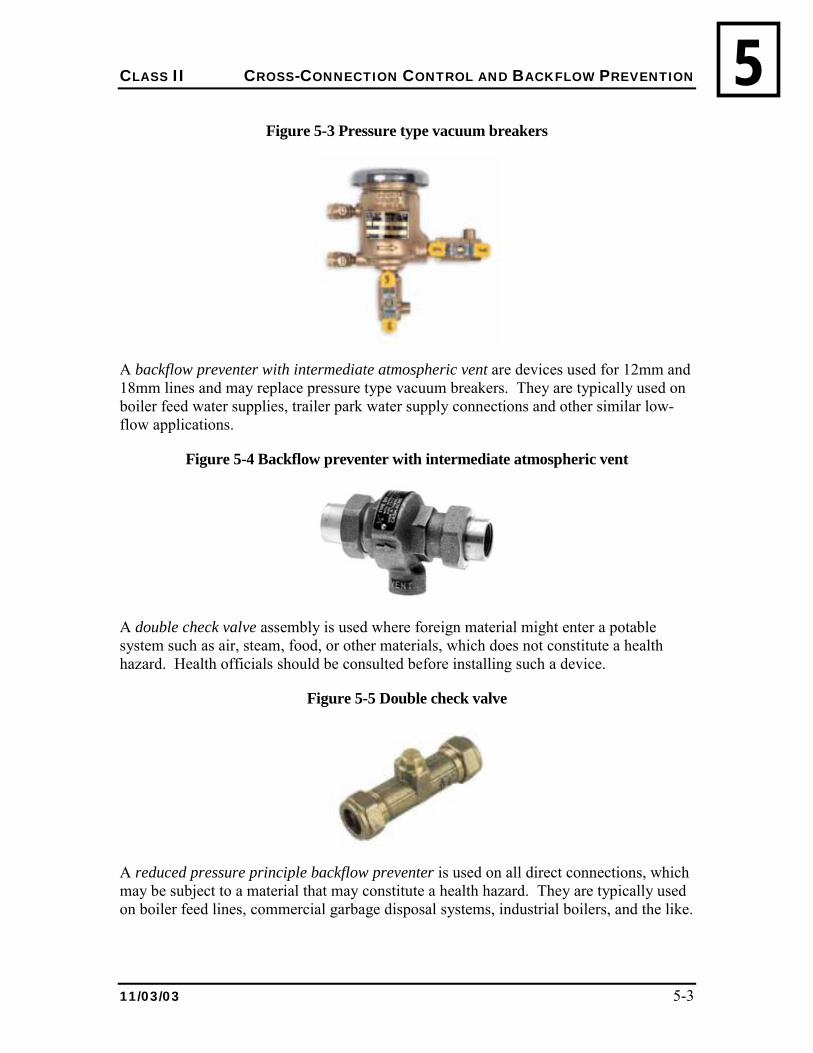
CLASS II CROSS-CONNECTION CONTROL AND BACKFLOW PREVENTION
11/03/03 5-3
5Figure 5-3 Pressure type vacuum breakers
A backflow preventer with intermediate atmospheric vent are devices used for 12mm and 18mm lines and may replace pressure type vacuum breakers. They are typically used on boiler feed water supplies, trailer park water supply connections and other similar low-flow applications.
Figure 5-4 Backflow preventer with intermediate atmospheric vent
A double check valve assembly is used where foreign material might enter a potable system such as air, steam, food, or other materials, which does not constitute a health hazard. Health officials should be consulted before installing such a device.
Figure 5-5 Double check valve
A reduced pressure principle backflow preventer is used on all direct connections, which may be subject to a material that may constitute a health hazard. They are typically used on boiler feed lines, commercial garbage disposal systems, industrial boilers, and the like.
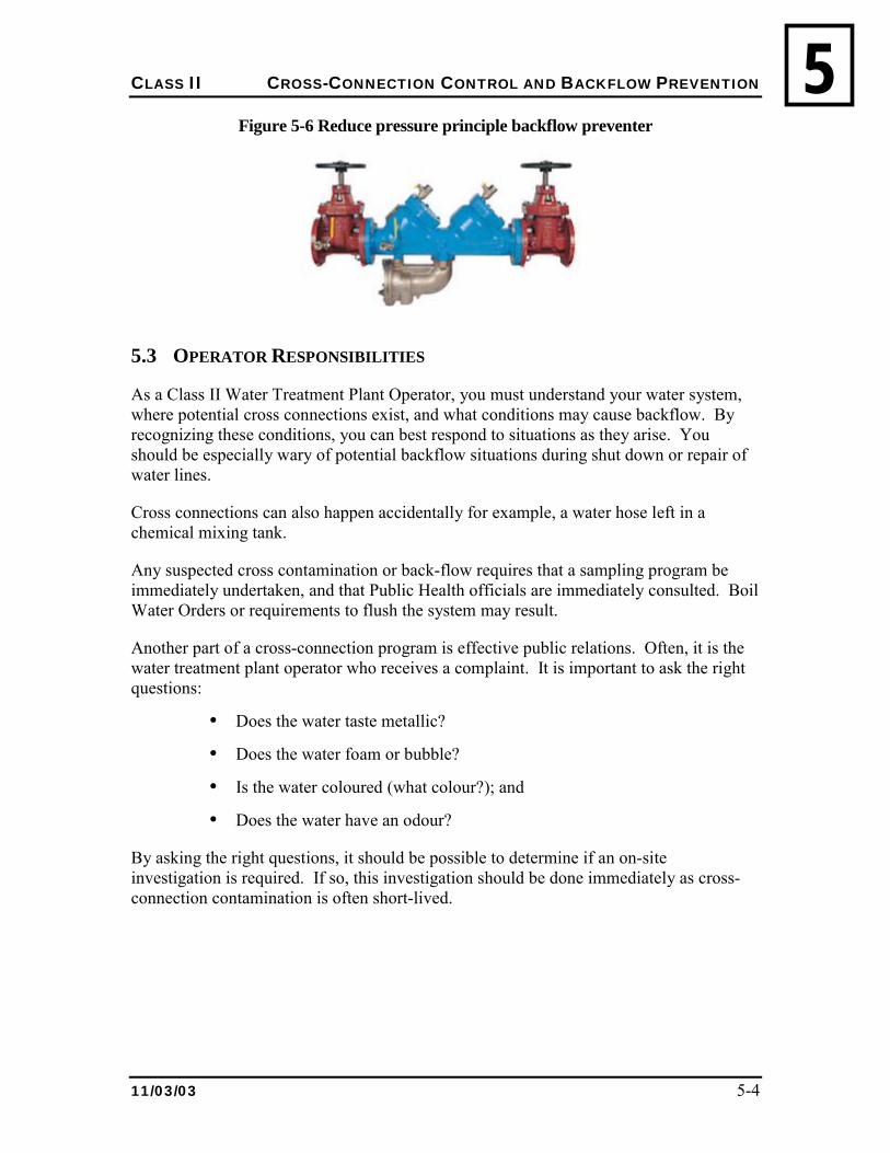
CLASS II CROSS-CONNECTION CONTROL AND BACKFLOW PREVENTION
11/03/03 5-4
5Figure 5-6 Reduce pressure principle backflow preventer
5.3 OPERATOR RESPONSIBILITIES
As a Class II Water Treatment Plant Operator, you must understand your water system, where potential cross connections exist, and what conditions may cause backflow. By recognizing these conditions, you can best respond to situations as they arise. You should be especially wary of potential backflow situations during shut down or repair of water lines.
Cross connections can also happen accidentally for example, a water hose left in a chemical mixing tank.
Any suspected cross contamination or back-flow requires that a sampling program be immediately undertaken, and that Public Health officials are immediately consulted. Boil Water Orders or requirements to flush the system may result.
Another part of a cross-connection program is effective public relations. Often, it is the water treatment plant operator who receives a complaint. It is important to ask the right questions:
• Does the water taste metallic?
• Does the water foam or bubble?
• Is the water coloured (what colour?); and
• Does the water have an odour?
By asking the right questions, it should be possible to determine if an on-site investigation is required. If so, this investigation should be done immediately as cross-connection contamination is often short-lived.
CLASS II CROSS-CONNECTION CONTROL AND BACKFLOW PREVENTION
11/03/03 5-5
55.4 REVIEW
1. Explain what a cross connection is.
2. Explain six methods to prevent back-flow caused by back-pressure and/or back syphonage.
CLASS II SAFETY
11/03/03 6-1
66.0 SAFETY
For specific details on aspects of safety refer to the:
• Class I Water Treatment Plant Operation Reference Manual;
• Department of Health and Social Services;
• NWT Worker�s Compensation Board; and
• The Manufacturer�s literature.
6.1 RESPONSIBILITY FOR SAFETY
The NWT Safety Act states that the responsibility for safety in the workplace lies with both workers and management. And, while that Act was written with good intentions and contains many important aspects of safety, at the end of the day, the Act won�t keep you safe. You are the only one who can keep yourself safe.
Often times there isn�t much accidental about accidents. Most incidents are the result of unsafe acts by workers including:
• Ignorance or unawareness of potential hazards;
• Indifference to safety;
• Poor work habits;
• Lack of attentiveness;
• Rushing the job;
• Failure to observe established safety procedures;
• Failure to wear safety equipment; and
• Poor physical condition.
Your positive, professional attitude toward safety will keep you injury free. It is the worker�s responsibility to:
• Work in accordance with established safety procedures;
• Obey established safety rules;
• Wear appropriate safety equipment correctly;
• Report all accidents, no matter how minor;
• Familiarize themselves with MSDS;
CLASS II SAFETY
11/03/03 6-2
6• Apply for appropriate safety training
• Report potential safety hazards; and
• Participate in safety programs (your safety committee).
Management is responsible for providing a safe working environment by:
• Ensuring that all plants and equipment are built and maintained in accordance with appropriate safety standards;
• Providing adequate funding for the proper maintenance of plants and equipment;
• Establishing, promoting, and enforcing a safety policy; and
• Establishing a safety-training program.
Topic for Discussion
How does the operator participate in a safety program when they most often work alone?
6.2 SAFETY PROGRAMS
Safety programs are intended to reduce the frequency of accidents. If such programs are to be effective, all workers must participate fully in them. Training is an essential part of any safety program. The major topics should include:
• Proper operation of unfamiliar equipment;
• Hazards of chemicals;
• First Aid;
• Electrical safety procedures;
• Fire protection systems;
• Operating and maintenance procedures; and
• Entry into confined spaces.
6.3 PLANT SAFETY
Most incidents result from slips and falls, and from lifting heavy objects. Ensure that:
• The plant floor and walkways are clean and dry;
CLASS II SAFETY
11/03/03 6-3
6• Ice and snow do not get an opportunity to accumulate, especially in areas that require
frequent access;
• Ice and snow are removed from areas before accessing them; and
• Care is taken in lifting heavy objects and transporting tools to a job site.
6.4 ELECTRICAL SAFETY
Below are some general electrical safety tips that are very easy to use and will reduce your potential for electric shock.
• Make sure all equipment is grounded. Ground fault circuit interrupters (GFCIs) should be used in areas where workers are exposed to wet or humid conditions. Do not touch exposed surface connectors.
• Never reverse the polarity when plugging in equipment. That is, do not reverse the plug and put the small prong into the larger socket hole and the large prong into the smaller hole. When you reverse the polarity, in many instances, the voltage will still be present in the piece of equipment when it is turned off. If that piece of equipment is dropped into water, shock may occur.
• Do not use extension cords that are damaged or have cuts in the insulation. Only use extension cords which have a ground wire (i. e., three pronged).
• Never break off the ground prong of a three prong plug to allow you to use it in a two prong outlet. Any cord with the prong missing should be put out of service. If the ground prong is removed the piece of equipment is no longer grounded.
• Whenever you have to work on a piece of equipment, lockout and tag the electrical source to that piece of equipment to make sure that it is de-energized.
• Routinely inspect all cords, plugs, and electrical equipment for damage.
6.4.1 LOCKOUT/TAGOUT
Lockout/Tagout is a method of keeping equipment from being set in motion and endangering workers needless deaths and serious injuries to service and maintenance workers.
Before any maintenance is performed on equipment all sources of electricity as well as process lines (i.e. steam line, cryogen feed lines, etc.) shall be locked- out and tagged- out.
Lockout/ tagout procedures usually include:
CLASS II SAFETY
11/03/03 6-4
6• Identifying all energy sources to the piece of equipment;
• Turning off and shutting down all appropriate valves, switches, and circuit breakers;
• Locking out the piece of equipment by applying a lockable device over the energy- isolating mechanism to hold it in the safe or off position. Every worker who will be working on the equipment should attach a personal lock to the isolating device;
• Applying a tag to the isolation source identifying the work to be done and the person who applied it;
• After the piece of equipment is locked and tagged out, it should be checked to make sure that energy sources were not missed;
• Verify the main disconnect switch or circuit breaker can't be moved to the on position;
• Use a voltmeter or other equipment to check the switch; and
• Press all start buttons and other activating controls on the equipment itself.
6.4.2 REMOVING LOCKOUT/TAGOUT EQUIPMENT
Lockout/ tagout equipment should only be removed when the maintenance work is complete and the equipment has been determined ready for operation by qualified personnel. Except in emergencies, the removal of lockout/ tagout devices should only be done by the person who put it on.
6.5 INFECTIONS AND INFECTIOUS DISEASES
The Department of Health and Social Services advises that you should keep your immunization shots up to date including Hepatitus A, Tetanus/Diptheria, and Red Measles/German Measles/Mumps. These are available from the Public Health Nurse in your community.
Make sure that you administer first aid to every cut.
6.6 HAZARDOUS GASES
There are many hazardous gases and vapours potentially present in water treatment plants, especially in confined spaces. These gases can make the atmosphere:
• Toxic;
• Explosive;
• Deficient in oxygen; or
• Any combination of the above.
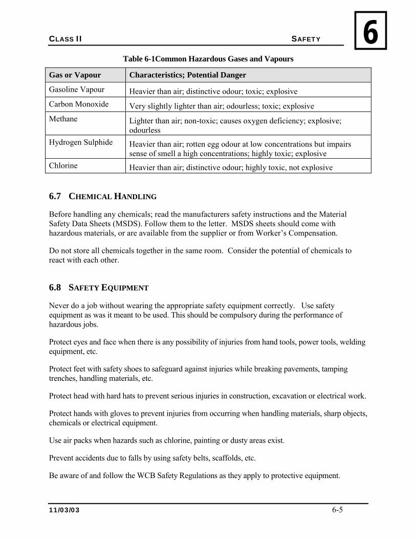
CLASS II SAFETY
11/03/03 6-5
6Table 6-1Common Hazardous Gases and Vapours
Gas or Vapour Characteristics; Potential Danger
Gasoline Vapour Heavier than air; distinctive odour; toxic; explosive Carbon Monoxide Very slightly lighter than air; odourless; toxic; explosive Methane Lighter than air; non-toxic; causes oxygen deficiency; explosive;
odourless Hydrogen Sulphide Heavier than air; rotten egg odour at low concentrations but impairs
sense of smell a high concentrations; highly toxic; explosive Chlorine Heavier than air; distinctive odour; highly toxic, not explosive
6.7 CHEMICAL HANDLING
Before handling any chemicals; read the manufacturers safety instructions and the Material Safety Data Sheets (MSDS). Follow them to the letter. MSDS sheets should come with hazardous materials, or are available from the supplier or from Worker�s Compensation.
Do not store all chemicals together in the same room. Consider the potential of chemicals to react with each other.
6.8 SAFETY EQUIPMENT
Never do a job without wearing the appropriate safety equipment correctly. Use safety equipment as was it meant to be used. This should be compulsory during the performance of hazardous jobs.
Protect eyes and face when there is any possibility of injuries from hand tools, power tools, welding equipment, etc.
Protect feet with safety shoes to safeguard against injuries while breaking pavements, tamping trenches, handling materials, etc.
Protect head with hard hats to prevent serious injuries in construction, excavation or electrical work.
Protect hands with gloves to prevent injuries from occurring when handling materials, sharp objects, chemicals or electrical equipment.
Use air packs when hazards such as chlorine, painting or dusty areas exist.
Prevent accidents due to falls by using safety belts, scaffolds, etc.
Be aware of and follow the WCB Safety Regulations as they apply to protective equipment.
CLASS II SAFETY
11/03/03 6-6
66.9 CONFINED SPACE ENTRY
Never enter a confined space unless you have been trained to do so. Always follow the proper entry procedures:
• Ensure that there are at least two other people present to pull you out (not go in after you). A mechanical lifting device may be required;
• Test the atmosphere with a commercial gas tester (refer to WCB for safe limits). If it is unsafe, don�t enter until it is safe or you have the proper protective equipment;
• If the atmosphere is unsafe ventilate with a portable blower. Test again. If necessary use a self-contained breathing apparatus; and
• Wear a safety harness, hardhat, and other safety equipment as appropriate to the environment.
People die every year in confined spaces. Their friends die, or are badly injured, trying to save them. Entering a confined space is serious business. Take any other attitude and you could be dead.
6.10 SAFETY ADMINISTRATION RESPONSIBILITIES
As a Class II Community Works Operator employed in the north, you may find that you most often work alone, or you may find yourself in a supervisory position. In either case, you will be required to perform some administrative duties.
There are a number of administrative factors to consider when managing the hazards at your work site. As an administrator, you become responsible for ensuring that:
• WHMIS and Safety Act regulations are complied with;
• Necessary safety equipment is on site and maintained;
• Regular safety checks of the site are conducted;
• Accident reports are kept up-to-date; and
• Everyone you work with is educated about the hazards associated with your plant.
It may be your responsibility to ensure that you, or at least one employee at the plant, is certified in Standard First Aid. In a plant where there are five or more people working, it is a Worker�s Compensation Board requirement that at least one person is certified in standard first aid.
If the proper safety equipment is not available on site, it may be your responsibility to buy it from your local hardware/clothing store, or order it from one of the many mail order safety companies.
CLASS II SAFETY
11/03/03 6-7
6The NWT Safety Act contains 486 paragraphs legislating health and safety regulations in the NWT. Of the 486 paragraphs, 81 apply indirectly to the Community Works Operator and the sewage and water plant operator. The other 405 paragraphs apply to construction and maintenance.
It is important to familiarize yourself with the regulations that pertain to the hazards in your workplace to ensure that your plant complies with the regulations. For example, the NWT Safety Act requires that all establishments have a copy of the Act on site to ensure that all employees have access to that information.
As your part in the administration of the sewage and water plant, Table 6.2 shows a checklist of NWT Safety Act requirements and WHMIS should be reviewed periodically to ensure that your plant provides a safe working environment.
You should be able to answer �Yes� to each question.
6.11 SUMMARY
This section has only briefly discussed some of many important safety aspects. More specific safety information can be found in by contacting WCB and referring to your Plant O&M manuals and MSDS sheets. Safety is the most important concern for operators and you should learn and practice safety every day.
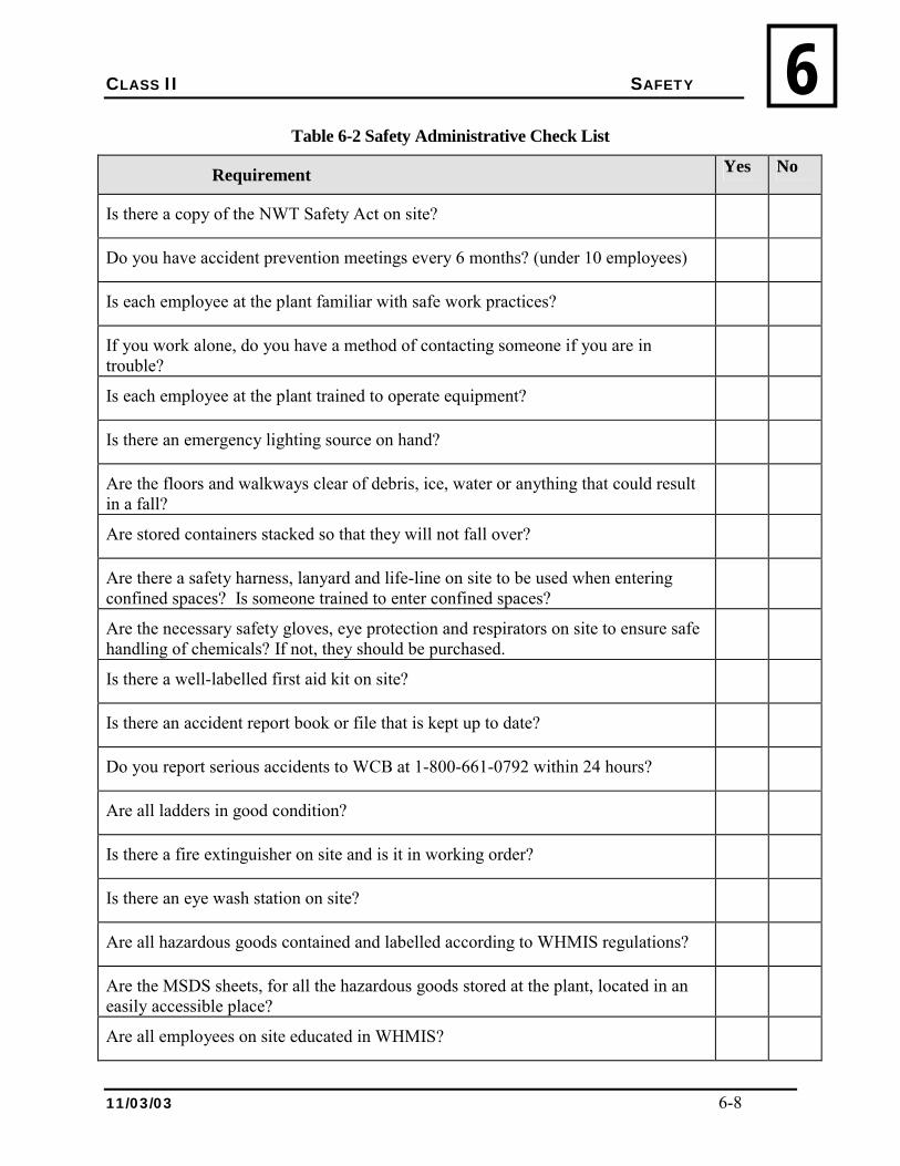
CLASS II SAFETY
11/03/03 6-8
6Table 6-2 Safety Administrative Check List
Requirement Yes No
Is there a copy of the NWT Safety Act on site?
Do you have accident prevention meetings every 6 months? (under 10 employees)
Is each employee at the plant familiar with safe work practices?
If you work alone, do you have a method of contacting someone if you are in trouble?
Is each employee at the plant trained to operate equipment?
Is there an emergency lighting source on hand?
Are the floors and walkways clear of debris, ice, water or anything that could result in a fall?
Are stored containers stacked so that they will not fall over?
Are there a safety harness, lanyard and life-line on site to be used when entering confined spaces? Is someone trained to enter confined spaces?
Are the necessary safety gloves, eye protection and respirators on site to ensure safe handling of chemicals? If not, they should be purchased.
Is there a well-labelled first aid kit on site?
Is there an accident report book or file that is kept up to date?
Do you report serious accidents to WCB at 1-800-661-0792 within 24 hours?
Are all ladders in good condition?
Is there a fire extinguisher on site and is it in working order?
Is there an eye wash station on site?
Are all hazardous goods contained and labelled according to WHMIS regulations?
Are the MSDS sheets, for all the hazardous goods stored at the plant, located in an easily accessible place?
Are all employees on site educated in WHMIS?

CLASS II SAFETY
11/03/03 6-9
66.12 REVIEW
1. Describe the measures you use to ensure your operations are safe.
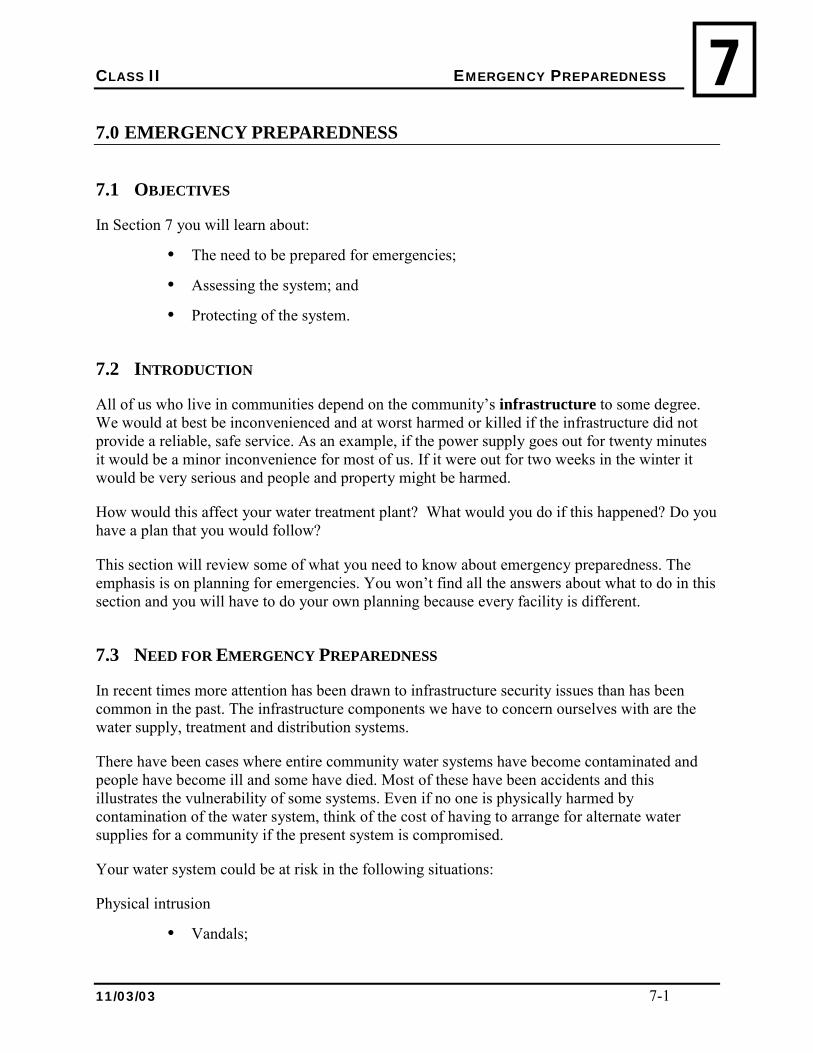
CLASS II EMERGENCY PREPAREDNESS
11/03/03 7-1
77.0 EMERGENCY PREPAREDNESS
7.1 OBJECTIVES
In Section 7 you will learn about:
• The need to be prepared for emergencies;
• Assessing the system; and
• Protecting of the system.
7.2 INTRODUCTION
All of us who live in communities depend on the community�s infrastructure to some degree. We would at best be inconvenienced and at worst harmed or killed if the infrastructure did not provide a reliable, safe service. As an example, if the power supply goes out for twenty minutes it would be a minor inconvenience for most of us. If it were out for two weeks in the winter it would be very serious and people and property might be harmed.
How would this affect your water treatment plant? What would you do if this happened? Do you have a plan that you would follow?
This section will review some of what you need to know about emergency preparedness. The emphasis is on planning for emergencies. You won�t find all the answers about what to do in this section and you will have to do your own planning because every facility is different.
7.3 NEED FOR EMERGENCY PREPAREDNESS
In recent times more attention has been drawn to infrastructure security issues than has been common in the past. The infrastructure components we have to concern ourselves with are the water supply, treatment and distribution systems.
There have been cases where entire community water systems have become contaminated and people have become ill and some have died. Most of these have been accidents and this illustrates the vulnerability of some systems. Even if no one is physically harmed by contamination of the water system, think of the cost of having to arrange for alternate water supplies for a community if the present system is compromised.
Your water system could be at risk in the following situations:
Physical intrusion
• Vandals;
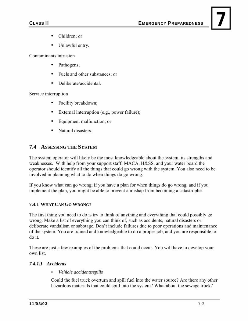
CLASS II EMERGENCY PREPAREDNESS
11/03/03 7-2
7• Children; or
• Unlawful entry.
Contaminants intrusion
• Pathogens;
• Fuels and other substances; or
• Deliberate/accidental.
Service interruption
• Facility breakdown;
• External interruption (e.g., power failure);
• Equipment malfunction; or
• Natural disasters.
7.4 ASSESSING THE SYSTEM
The system operator will likely be the most knowledgeable about the system, its strengths and weaknesses. With help from your support staff, MACA, H&SS, and your water board the operator should identify all the things that could go wrong with the system. You also need to be involved in planning what to do when things do go wrong.
If you know what can go wrong, if you have a plan for when things do go wrong, and if you implement the plan, you might be able to prevent a mishap from becoming a catastrophe.
7.4.1 WHAT CAN GO WRONG?
The first thing you need to do is try to think of anything and everything that could possibly go wrong. Make a list of everything you can think of, such as accidents, natural disasters or deliberate vandalism or sabotage. Don�t include failures due to poor operations and maintenance of the system. You are trained and knowledgeable to do a proper job, and you are responsible to do it.
These are just a few examples of the problems that could occur. You will have to develop your own list.
7.4.1.1 Accidents
• Vehicle accidents/spills Could the fuel truck overturn and spill fuel into the water source? Are there any other hazardous materials that could spill into the system? What about the sewage truck?
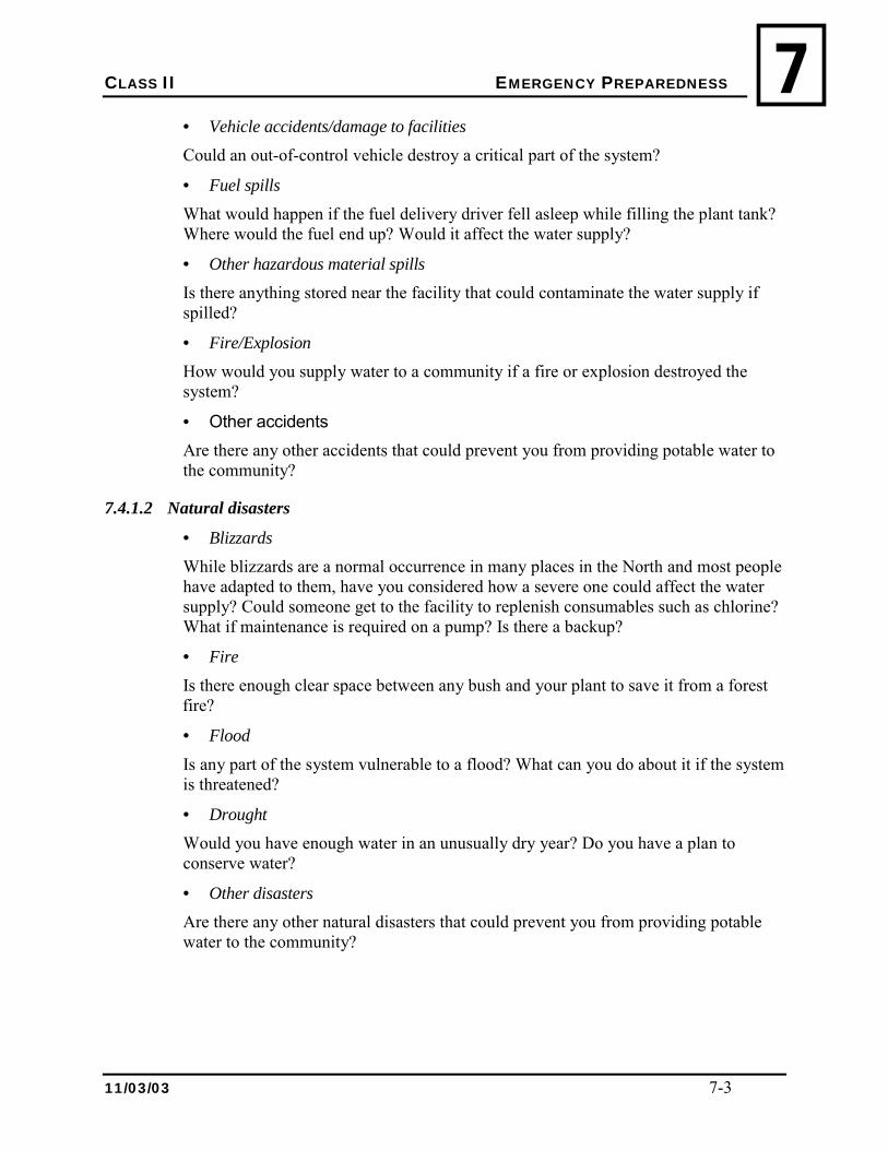
CLASS II EMERGENCY PREPAREDNESS
11/03/03 7-3
7• Vehicle accidents/damage to facilities Could an out-of-control vehicle destroy a critical part of the system?
• Fuel spills What would happen if the fuel delivery driver fell asleep while filling the plant tank? Where would the fuel end up? Would it affect the water supply?
• Other hazardous material spills Is there anything stored near the facility that could contaminate the water supply if spilled?
• Fire/Explosion How would you supply water to a community if a fire or explosion destroyed the system?
• Other accidents Are there any other accidents that could prevent you from providing potable water to the community?
7.4.1.2 Natural disasters
• Blizzards While blizzards are a normal occurrence in many places in the North and most people have adapted to them, have you considered how a severe one could affect the water supply? Could someone get to the facility to replenish consumables such as chlorine? What if maintenance is required on a pump? Is there a backup?
• Fire Is there enough clear space between any bush and your plant to save it from a forest fire?
• Flood Is any part of the system vulnerable to a flood? What can you do about it if the system is threatened?
• Drought Would you have enough water in an unusually dry year? Do you have a plan to conserve water?
• Other disasters Are there any other natural disasters that could prevent you from providing potable water to the community?
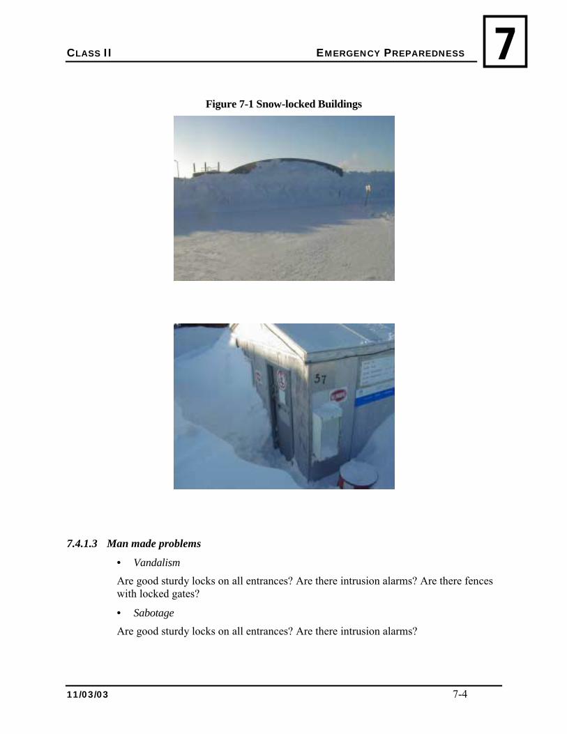
CLASS II EMERGENCY PREPAREDNESS
11/03/03 7-4
7
Figure 7-1 Snow-locked Buildings
7.4.1.3 Man made problems
• Vandalism Are good sturdy locks on all entrances? Are there intrusion alarms? Are there fences with locked gates?
• Sabotage Are good sturdy locks on all entrances? Are there intrusion alarms?
CLASS II EMERGENCY PREPAREDNESS
11/03/03 7-5
77.4.2 WHAT PROTECTIONS ARE BUILT-IN?
7.4.2.1 Accidents
• Vehicle accidents/spills Are there safeguards in place to prevent vehicle accidents from compromising the system? What are they?
• Vehicle accidents/damage to facilities Are there safeguards in place to prevent vehicle accidents from compromising the system? What are they?
7.4.2.2 Fuel spills Is there proper spill containment in place to prevent fuel spills from compromising the water system? Is it properly maintained?
7.4.2.3 Other hazardous material spills Is there proper spill containment in place to prevent fuel spills from compromising the water system? Is it properly maintained?
7.4.2.4 Fire Do you have enough of the proper type of fire extinguishers in place? Are they accessible? Does the fire department know what chemicals you store and handle? Are they prepared to deal with chemical fires?
7.5 PROTECTING THE SYSTEM
7.5.1 RESPONSE PLANS
Now that you have an assessment of the system with a good idea of many of the things that can go wrong and some of the tools you have built in to the system to prevent or minimize damage, you should develop a plan to deal with emergencies. It is easier to follow a plan that has been carefully thought out, than it is to make it up as you go when there is a lot of pressure on you.
Decide what you would do if any, or several, of the emergencies happened. Write the plans down. Things you need to have in the response plan include: Who do you need to notify?
This could vary, depending on the nature of the emergency. It is likely to always include the Senior Administrative Officer or Band Manager. It may include the Environmental Health Officer. It may also include the fire department, police and MACA Regional Office. Remember when you contact them that you need to be able to provide clear, concise and correct information. Don�t guess about things you are not sure about.
CLASS II EMERGENCY PREPAREDNESS
11/03/03 7-6
7 What do you need to do?
Write down the steps that you would follow to rectify the problems. Write down any steps you would follow to provide temporary service.
What resources do you need?
List the support agencies, people, supplies and equipment you will need to rectify the problem. Write them down with contact numbers. List backups in case your primary resources are not available.
Your Senior Administrative Officer or Band Manager has to be involved in preparation of response plans. You will probably require information from others as you develop plans. It must be a team effort if it is likely to be successful.
Put all this information in a binder so you can update it. There should be a copy in your facility and in the community office. You should keep one at home. The fire department should have one. Other copies may be required.
Review the plan at least once a year. Update it if new potential problems arise. Keep the contact information up-to-date.
Remember, the points in this section are intended as examples only. You will need to develop your own security plans, with help from others.
7.6 CONTINGENCY PLANNING
7.6.1 SPRING BREAK-UP
Spring break-up usually means a period of high turbidity and varying water quality. Long before break-up occurs you should have ordered and received essential chemicals and parts to maintain operation during this difficult period. It is advisable to follow your MMOS or work with MACA to establish a plan to deal with the spring break-up. Alarms should be tested to ensure proper operation. Often, a second shift is required to ensure the plant is fully operational. Operators should ensure that the plant has someone is available 24/7 until things stabilize.
7.6.2 FALL FREEZE-UP
You all know that if it can freeze it will, at the most inopportune time, and causing the greatest amount of damage to the most important component. Ensure that those things that can freeze are protected and can be recovered with no damage to the system. Ensure things that can freeze have spares in inventory. It is advisable to follow your MMOS or work with MACA to establish a plan to deal with the fall freeze-up. Long before freeze up occurs test freeze alarms to ensure proper operation and test heat trace cables to ensure they work. Turn them on.
CLASS II EMERGENCY PREPAREDNESS
11/03/03 7-7
77.6.3 HEAVY OR PROLONGED RAINFALL
Is your facility affected by rainfall? If so, then a constant weather watch is important to ensure continuing quality. When rainfall occurs of a quantity that can cause an effect, extra diligence is necessary to ensure water quality and proper disinfection. Depending on the severity, a call-out or two-shift operation may be required.
7.6.4 BACTERIAL CONTAMINATION
Sometimes a bacterial test will show an intrusion. While confirming the intrusion with a follow-up sample, the process of locating the problem begins. The best practice approach requires the isolation of your system�s components to locate the problem. Generally systems have the following components:
• Raw water source;
• Raw water piping to the treatment facility;
• The treatment facility;
• Storage;
• Piping to distribution;
• Distribution;
• In-home storage.
Take bacterial samples, daily if necessary or as directed by the Environmental Health Officer (EHO), from each of these components to determine the source. Then make repairs and sample again. Ensure you are in contact with your EHO throughout the process.
7.6.5 BOIL ORDERS
Some times the bacterial intrusion is so severe, or of a type that may cause disease, that a boil water order must be made. The EHO is responsible for issuing a boil water advisory, and the operator should follow instructions to the letter until the event has been remedied to the EHO�s satisfaction. The operator should ensure their free residual chlorine meets the regulatory requirement as a minimum.
7.7 REVIEW
Work on the exercises described in Section 7.4.1 and 7.5.1.
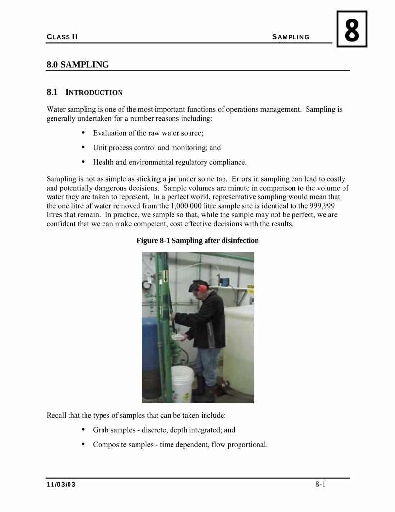
CLASS II SAMPLING
11/03/03 8-1
88.0 SAMPLING
8.1 INTRODUCTION
Water sampling is one of the most important functions of operations management. Sampling is generally undertaken for a number reasons including:
• Evaluation of the raw water source;
• Unit process control and monitoring; and
• Health and environmental regulatory compliance.
Sampling is not as simple as sticking a jar under some tap. Errors in sampling can lead to costly and potentially dangerous decisions. Sample volumes are minute in comparison to the volume of water they are taken to represent. In a perfect world, representative sampling would mean that the one litre of water removed from the 1,000,000 litre sample site is identical to the 999,999 litres that remain. In practice, we sample so that, while the sample may not be perfect, we are confident that we can make competent, cost effective decisions with the results.
Figure 8-1 Sampling after disinfection
Recall that the types of samples that can be taken include:
• Grab samples - discrete, depth integrated; and
• Composite samples - time dependent, flow proportional.
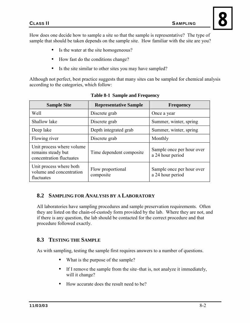
CLASS II SAMPLING
11/03/03 8-2
8How does one decide how to sample a site so that the sample is representative? The type of sample that should be taken depends on the sample site. How familiar with the site are you?
• Is the water at the site homogeneous?
• How fast do the conditions change?
• Is the site similar to other sites you may have sampled?
Although not perfect, best practice suggests that many sites can be sampled for chemical analysis according to the categories, which follow:
Table 8-1 Sample and Frequency
Sample Site Representative Sample Frequency
Well Discrete grab Once a year
Shallow lake Discrete grab Summer, winter, spring
Deep lake Depth integrated grab Summer, winter, spring
Flowing river Discrete grab Monthly
Unit process where volume remains steady but concentration fluctuates
Time dependent composite Sample once per hour over a 24 hour period
Unit process where both volume and concentration fluctuates
Flow proportional composite
Sample once per hour over a 24 hour period
8.2 SAMPLING FOR ANALYSIS BY A LABORATORY
All laboratories have sampling procedures and sample preservation requirements. Often they are listed on the chain-of-custody form provided by the lab. Where they are not, and if there is any question, the lab should be contacted for the correct procedure and that procedure followed exactly.
8.3 TESTING THE SAMPLE
As with sampling, testing the sample first requires answers to a number of questions.
• What is the purpose of the sample?
• If I remove the sample from the site�that is, not analyze it immediately, will it change?
• How accurate does the result need to be?
CLASS II REPRESENTATIVE SAMPLING
11/03/03 8-3
8• How quickly do I require the result?
• Can the sample be preserved?
• Do I trust my own lab technique?
Normally, to develop a data profile of the raw water source, or for health and environmental regulatory compliance, samples have to be both accurate and precise. These samples should be analyzed in a certified laboratory.
Some parameters such as pH, chlorine residual, temperature, and dissolved oxygen will change if the sample is removed from the site. These are normally done immediately on-site and, therefore, called field tests.
Unit process control and monitoring the results are normally required quickly and can be less accurate. These are often conducted using commercial test kits.
Some parameters, such as bacteria, cannot be preserved and need to be analyzed within a very short time frame. Other parameters can be preserved for a longer time. Before sampling, determine what parameters are to be analyzed and contact the lab for details on shipping time and preservation techniques. Most commercial labs will not analyze a sample that arrives late or is improperly preserved because they cannot guarantee the accuracy of the sample result.
8.4 QUALITY ASSURANCE AND QUALITY CONTROL
Quality assurance and quality control is a major program in commercial laboratories. In order to stay certified, a commercial laboratory must ensure their analytical techniques are constantly checked. In the unit process control and monitoring laboratory in your plant, you should also have a quality assurance and quality control program. Such a program involves a rigorous protocol for:
• Cleaning glassware and sample containers;
• Cleaning and calibration of test kits;
• Collection, preservation, and storage of water samples; and
• Testing standard solutions.
Testing standard solutions is a way to check your personal analysis technique when you use a test kit. Standard solutions, these are solutions with a known concentration of a parameter, are available commercially, or can be made in your laboratory. Standard solutions have a �best before� date after which they should be disposed of as their �standard� is now suspect.
Another way to check your personal analysis technique is to split a sample into two, analyze one sample yourself and send the other to a commercial lab.
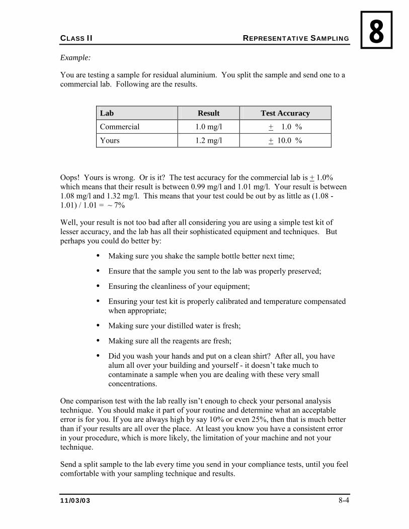
CLASS II REPRESENTATIVE SAMPLING
11/03/03 8-4
8Example:
You are testing a sample for residual aluminium. You split the sample and send one to a commercial lab. Following are the results.
Lab Result Test Accuracy
Commercial 1.0 mg/l + 1.0 %
Yours 1.2 mg/l + 10.0 %
Oops! Yours is wrong. Or is it? The test accuracy for the commercial lab is + 1.0% which means that their result is between 0.99 mg/l and 1.01 mg/l. Your result is between 1.08 mg/l and 1.32 mg/l. This means that your test could be out by as little as (1.08 - 1.01) / 1.01 = ~ 7%
Well, your result is not too bad after all considering you are using a simple test kit of lesser accuracy, and the lab has all their sophisticated equipment and techniques. But perhaps you could do better by:
• Making sure you shake the sample bottle better next time;
• Ensure that the sample you sent to the lab was properly preserved;
• Ensuring the cleanliness of your equipment;
• Ensuring your test kit is properly calibrated and temperature compensated when appropriate;
• Making sure your distilled water is fresh;
• Making sure all the reagents are fresh;
• Did you wash your hands and put on a clean shirt? After all, you have alum all over your building and yourself - it doesn�t take much to contaminate a sample when you are dealing with these very small concentrations.
One comparison test with the lab really isn�t enough to check your personal analysis technique. You should make it part of your routine and determine what an acceptable error is for you. If you are always high by say 10% or even 25%, then that is much better than if your results are all over the place. At least you know you have a consistent error in your procedure, which is more likely, the limitation of your machine and not your technique.
Send a split sample to the lab every time you send in your compliance tests, until you feel comfortable with your sampling technique and results.
CLASS II REPRESENTATIVE SAMPLING
11/03/03 8-5
88.5 REVIEW
1. Describe how to check the accuracy of your samples.
2. What factors should the operator take into account when deciding what kind of samples should be taken?
CLASS II ADMINISTRATION
11/03/03 9-1
99.0 ADMINISTRATION
9.1 MAINTENANCE MANAGEMENT
All physical facilities pass through life cycles that are complex, yet identifiable and definable. The cycle commences with the creation of the new facility and proceeds through stages of initial use, modification and adaptation to final deterioration and obsolescence.
In the crucial middle stages of active use, facility maintenance often is overlooked. Care and expense is lavished upon design but little thought given to upkeep. Yet over the useful life of the facility the maintenance costs normally will exceed the construction or purchase costs.
Maintenance is necessary to preserve the facility and to keep it functioning. Maintenance management is a positive maintenance philosophy, which holds that:
1. Maintenance can be planned, organized, directed and controlled, in other words it can be managed.
2. Maintenance policies and objectives can be established and programs for their accomplishment can be determined.
3. The bulk of the maintenance workload is:
• Definable in terms of distinct functions;
• Amenable to standardization in terms of service frequencies and production rates;
• Quantifiable in work terms, in financial terms, and in terms of physical resource requirements;
• Capable of being scheduled;
• Controllable both in work as well as financial terms.
This is called preventative maintenance.
4. The remaining fraction of the workload is maintenance, which tends to be reactive. This work must still be planned, organized, directed and controlled with the only difference being that these functions simply take place at a lower level of certainty.
5. Resource allocation can be rationalized.
CLASS II ADMINISTRATION
11/03/03 9-2
9It must be recognized, however, that maintenance management is a tool for management - powerful but, nevertheless, a tool. It supplements but does not replace good, positive, enlightened management, or proper, timely maintenance.
The annual maintenance work program and budget for the Water Treatment Facility should be based on:
• An inventory of maintainable assets;
• The work activity to perform the maintenance;
• A quality standard describing how well the maintenance is to be performed � level-of-service;
• Performance standards which identify the quantity of work to achieve the level-of-service and the productivity of the work crew; and
• The costs of each resource of the work program which becomes a performance budget.
This program will be used to substantiate the estimates for a fiscal year.
The water program is very costly in your community and a significant portion of overall community expenses. Add now the cost of water treatment and the cost increase significantly. These costs are born primarily by user-fees. Effective, efficient operation reduces the cost of operations and, therefore, the cost to the user.
9.2 RECORDS KEEPING
Operators have a responsibility for keeping accurate and daily records of system operation and maintenance duties. Records are kept to predict and control costs, budget, identify problem maintenance areas and to provide a record of ensuring legal commitments are met. Four types of records are normally kept:
1. Plant Operational Records
2. Maintenance Records
3. Complaints Log
4. Observations Log
9.2.1 PLANT OPERATIONAL RECORDS
9.2.1.1 Weather
• Air temperature
CLASS II ADMINISTRATION
11/03/03 9-3
9• Cloud cover
• Rainfall / snowfall
9.2.1.2 Water Supply
• Water temperature
• Reservoir inflow and outflow
• Production rates
9.2.1.3 Water Treatment Plant
• Inlet and outlet temperature, pH
• Inflow rate and volume
• Treated water rate and volume
• Backwash volume
• Backwash rate
• Clear well level
• Media condition
• Backwash frequency
9.2.1.4 Chemical Use
• Chemical inventories
• Chemical use
• Chemical dosage rates
9.2.1.5 Quality Control Tests
• Turbidity
• Chlorine
• Bacteria
• Jar tests
• Unit process tests
• Tests required by the Department of Health & Social Services
• Colour
CLASS II ADMINISTRATION
11/03/03 9-4
9• pH
• Iron
• Manganese
• Aluminium
• Hardness
• Alkalinity.
9.2.1.6 Distribution System
• Temperature
• Pressure
• Free residual chlorine
• Total residual chlorine
• Turbidity
• Colour
• Volume to piped system
• Volume to trucked system
• Volume unaccounted for
9.2.2 MAINTENANCE RECORDS
As facilities and components age, the cost of keeping them in top-notch operating condition increases. Complete maintenance records kept for the life the plant are essential to identify problem maintenance areas and components so that retrofit and replacement programs can be developed. Costs should also be identified including:
• Labour and supervisory costs;
• Equipment;
• Operating and maintenance supplies;
• Contractors and tradesmen; and
• Utilities costs.
Non-routine maintenance procedures that are difficult to schedule in with the maintenance management program, such as topping up or replacing filtration media, should also be kept in these records.
CLASS II ADMINISTRATION
11/03/03 9-5
99.2.3 COMPLAINTS LOG
A written record of contacts with the public should be kept, and should include the following:
• Telephone logs identifying date, time, name of caller, address of caller and/or site of complaint, and nature of the complaint;
• Immediate action taken;
• Follow up action required; and
• Any appropriate comments.
Any public comments or concerns should be passed on to your immediate supervisor.
9.2.4 OBSERVATIONS LOG
A record of your personal observations about tests, plant operations, names of suppliers, supplier�s response to your emergency calls, how the weather affects the water quality; the competency of contractors, and anything else.
9.3 INVENTORY CONTROL
Inventory control is an important part of the administration of your water treatment plants. Since a year-round road is not present to many communities in the NWT, it is important to know exactly how many supplies are present and need to be ordered since supplies may often be brought up by ice roads, barge or by air.
An inventory control system is the best way to ensure than the necessary supplies for your plant will be there when you need them. This can include chemicals, pumps, filters, media, valves, throttles and any other component of the plant. Operators are encouraged to use the MMOS or work with MACA to determine the optimal solution for your plant.
The best way to keep track of your inventory is by using an inventory sheet. The sheet should list all the components of the plant that will require replacing or restocking on a regular basis. An example of an inventory sheet is shown in Figure 9.1. The inventory sheet should also include emergency replacements supplies such as extra pumps and valves. The supplier and contact number should be on the sheet to make for easy ordering. The sheet will also list the amount of current stock and the minimum stock required to be in storage, as well as the amount the ideal amount of stock to have when ordering. The sheet should be updated on a regular basis and be as accurate as possible.
The minimum stock and ideal stock levels should be determined by looking at how often the certain part of supply gets used and by how fast it can be received when ordered.
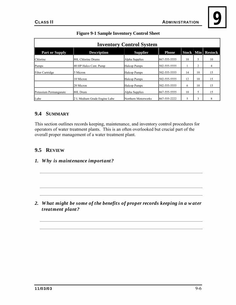
CLASS II ADMINISTRATION
11/03/03 9-6
9Figure 9-1 Sample Inventory Control Sheet
Inventory Control System Part or Supply Description Supplier Phone Stock Min Restock
Chlorine 80L Chlorine Drums Alpha Supplies 867-555-5555 10 5 10
Pumps 40 HP Halco Cent. Pump Halcop Pumps 502-555-5555 1 2 4
Filter Cartridge 5 Micron Halcop Pumps 502-555-5555 14 10 15
10 Micron Halcop Pumps 502-555-5555 12 10 15
20 Micron Halcop Pumps 502-555-5555 6 10 15
Potassium Permanganate 80L Drum Alpha Supplies 867-555-5555 10 5 15
Lube 2 L Medium Grade Engine Lube Northern Motorworks 867-555-2222 5 3 8
9.4 SUMMARY
This section outlines records keeping, maintenance, and inventory control procedures for operators of water treatment plants. This is an often overlooked but crucial part of the overall proper management of a water treatment plant.
9.5 REVIEW
1. Why is maintenance important?
2. What might be some of the benefits of proper records keeping in a water treatment plant?

ADDENDUM A
GLOSSARY
GLOSSARY
Adsorption The taking up of one substance into the body of another
ABS
Abbreviation for Sodium alkyl benzene sulfonate Adsorbing
(1) The adherence of a gas, liquid or dissolved solid onto the surface of a solid. (2) A change in concentration of a gas or solute at the interface of a two-phase
system. Aeration
The bringing about of contact between air and a liquid by one or more of the following methods:
a) spraying of liquids into the air, b) bubbling air through the liquid, c) agitating the liquid to promote surface adsorption of air.
Aesthetic Pleasing to the senses – taste, smell, colour Air gap
The distance between the lowest opening of a pipe supplying water to a tank and the upper rim of the tank
Algae
Tiny plants, usually living in water and often green in colour. Algicide
Anything applied to kill or control algae.
Alkaline Basic, ph below 7. Alkaninity Alkalinity is water’s capacity to buffer the lowering of pH by adding acids to the water. Usually measured is mg/L of CaCO3.
Anaerobic Without, in absence of oxygen Anion Chloride ion (Cl-) is an anion. A negatively charged ion in an electrolyte solution.
Aquifer
Porous, water-bearing formation of rock, sand, or gravel.
Autotrophic bacteria Bacteria that derive their energy from the light through photosynthesis. Backflow
The backing up of water through a conduit or channel in the direction that is opposite to normal flow.
Backwashing The process of reversing the flow of water back through a filter to remove any trapped solids.
Bacteria
Single celled microscopic organisms living in soil, water, organic matter or the bodies of plants or animals.
Bacteriological The study of bacteria
Cavitation
Cavitation is accompanied by loud noises that sound like someone is pounding on the impeller or gate with a hammer. The formation and collapse of a gas pocket or bubble on the blade of an impeller or the gate of a valve. The collapse of this gas pocket or bubble drives water into the impeller or gate with a terrific force that can cause pitting on the impeller of gate surface.
Clarification
A process where water in a tank or basin is held for a period of time and heavier suspended solids settle to the bottom
Chloramines Compounds formed by the reaction of watery chlorine with ammonia
Chlorine demand
The difference between the amount of chlorine added to water and the amount of chlorine residual left after a certain length of time
Chlorine residual The amount of chlorine still left available after a certain length of contact time.
Clear well
Reservoir for storing filtered water. Coagulants
In water and wastewater, chemicals used to thicken finely divided suspended solids into groups for easy removal.
Coagulation
In water treatment, the destabilization and initial putting together of colloidal and finely divided suspended matter by the addition of a floc forming chemical or by biological processes.
Coliform
A group of bacteria that normally live in the intestines of mammals and are also found elsewhere in nature. They are indicators of faecal Contamination in the water supply.
Colloidal
Particles are too finely divided to settle; requiring coagulation, biochemical action, or membrane filtration for removal.
Combined chlorine Chlorine that is bound to other elements such as ammonia, nitrogen or organic compounds but is still an effective disinfectant. Combined chlorine has been found to be more effective than free chlorine in controlling post-disinfection bacterial growth. Chloramines are an example of combined chlorine
Compound A pure substance composed of two or more elements whose composition is constant. For example, table salt (sodium chloride) is a compound. Cryptosporidium A protozoa that can causes severe diarrhoea ior even death is Detention Time The length of time that water or wastewater is held in a unit for any treatment. Deteriorate To make worse, to wear down
Diatomaceous earth
A fine, siliceous (made with silica) “earth” composed mainly of the skeletal remains of diatoms.
Divalent Cation An atom with an electric charge of 2+ also referred to as alkaline-earth elements. Primary constituents in the determination of a water’s alkalinity.
Disinfection The process done to kill or inactivate most microorganisms in water, including pathogenic (disease-causing) bacteria. There are several ways to disinfect. Chlorination is the usual one.
Due Diligence The level of judgement, care, caution, determination and activity that a person would
reasonably be expected to do under particular circumstances. Driver Any machine part that communicates motion to another part E. coli
E. coli, Escherichia coli, is a specific type of faecal coliform. Water Plant Operators often test for E. coli as it has a higher likelihood of being disease-causing than other faecal coliforms.
Faecal coliform Colony forming bacteria that is associated with either animal or human faeces. An
indicator of contamination of disease forming organisms Finished water Water that has passed through a water treatment plant; all the treatment processes are
completed or “finished”. The water is ready to be delivered to consumers. Flagellates Microorganisms that move by the action of tail- like projections. Flagella Whip-like appendages Floc
Small jelly- like masses formed in a liquid by adding a coagulant. Flocculation
The collection of coagulated suspended solids into a mass by gentle stirring. Flocculation aids
Materials added to liquid to improve the condition of and form flocs,
Flocculator Mechanical equipment used to encourage the formation of floc in liquid.
Flora Plants or vegetation. Free available chlorine
Chlorine present as Cl2, HOCl and OCl- is free available chlorine. It is used to kill bacteria in the water after water leaves the treatment plant. The active chlorine in the water for disinfection is also called free chlorine residual.
Freshet The occurrence of a water flow resulting from sudden rain or melting snow. Green sand
A mineral (glauconite) material that looks like ordinary filter sand except that it is green in colour. Greensand is a natural ion exchange material which is capable of softening water.
Groundwater Water extracted from underground aquifers using wells Head
The vertical distance (in feet) equal to the pressure (in psi) at a specific point. The pressure head is equal to the pressure in psi times 2.31 ft/psi. Can also be measured in meters and pascals. See pressure head.
Heterotrophic plate count (HPC)
HPC is a method used to indicate the microbial quality of water. HPC is also known as Standard Plate Count.
Hydrologic cycle
The movement of water from the atmosphere to the earth and back to the atmosphere through precipitation, infiltration, storage, transpiration, evaporation etc.
Hydrolysis
The formation of an acid and a base from a salt by interaction with water; it is caused by the ionic dissociation of water.
Impound To gather and enclose. To keep separate. Impellers A rotating set of vanes in a pump designed to pump or lift water
Impermeable Not easily penetrated. The property of a material or soil that does not allow, or allows with great difficulty, the passage of water. Opposite of permeable. Impervious Not penetrable. Indicator bacteria
Bacteria that point to the possible presence of intestinal pathogens, for example, coliforms or E. coli.
Influent
Water flowing into a treatment plant or any of its units Infrastructure -
A system of public works such as buildings, utilities and resources required for an activity.
Injection wells
Wells created to recharge groundwater. Inorganic
Made of matter that is not plant or animal.
Insoluble Cannot be dissolved in a liquid.
Intake The place at which fluid is taken into a pipe Ion exchange
A chemical process in which ions from two different molecules are exchanged. Ionization
The act or process of charging or treating with ozone. Also, the conversion of oxygen into ozone. Used for disinfection purposes.
Ionizing Creating ions by adding electrons to, or removing them from, atoms or molecules.
Iron Bacteria Bacteria that use iron as food and discharge its compounds in their life processes.
Kinetic Energetic or dynamic: in motion. Kinetic energy is energy possessed by a moving body of matter, such as water, as a result of its motion.
Leaching
Percolating (or bubbling) liquid through soil or other solids to remove the soluble ingredients.
Manganese green sand A green mineral material which has been treated with potassium permanganate (KMnO4).
Used for iron and manganese removal. Metabolism
The process in which food is used and wastes are formed by living matter. MF
Membrane filter (used in bacteriological lab test) Microbes
Living creatures of microscopic or submicroscopic size (e.g., bacteria, microscopic fungi) that digest decomposable materials through their metabolic activity. Microbes are the essential agents of decomposition and treatment in natural wastewater treatment systems such as septic systems. Also called Microorganisms.
Microorganisms
Very tiny organisms, either plant or animal, invisible or barely visible to the naked eye. MPN
Most Probable Number (used in bacteriological lab test). NSF
An international non-governmental, not- for-profit group that issues standards specializing in food, air, water and the environement.
Nutrient
Food for the growth of organisms. Organic
Made of matter that is plant or animal. Pathogens
Disease producing bacteria. Permeable
Having pores or openings that permit liquids or gases to pass through. pH
The measure of the acid/alkaline balance, expressed on a scale of 0 to 14, with 7 being neutral; 7 to 0 increasing acidity, and 7 to 14 increasing alkalinity.
Potable Safe to consume for human standards based on accepted standards. Polymer
A long chain molecule formed by lighter molecules. Polymers are used with other chemical coagulants to aid in binding small suspended particles to larger chemical flocs for their removal from the water.
Pressure head
A measure of the pressure exerted by a fluid expressed as elevation (e.g. metres or feet).
Prime or priming The action of filling a pump casing with water to remove the air. Many pumps must be primed before start-up or they will not pump water
Protozoan cysts
Harmful particles that can cause flu- like illnesses. Pseudomonad
Short rod shaped bacteria, some of which live on dead or decaying organic matter, or cause disease
Pumping level
The height where water stands in a well during pumping. Reducing agent
A substance such as iron that will readily donate (give up) electrons in an oxidition-reduction chemical reaction. The opposite is an oxidizing agent.
Reverse osmosis The application of pressure to a concentrated solution which causes the passage of a liquid from the concentrated solution to a weaker solution across a membrane. The membrane allows the passage of the water but not the dissolved solids. The liquid produced is demineralised water.
Rotary Moving around a central axis Sedimentation
A water treatment process in which solid particles settle out of the water being treated in a sedimentation basin.
Septic
A condition produced by bacteria when all oxygen supplies are depleted (anaerobic).
Short retention pool A tank or pond as part of a process, with a capacity to hold about an hour or less of flowing water. Slurry, Slurries
A watery mixture or suspension of insoluble (not dissolved) matter; a thin, watery mud or any substance resembling it (such as grit slurry or lime slurry).
Solution A liquid mixture of dissolved substances. In a solution, it is impossible to see all the separate parts. I.e. coffee with cream and sugar.
Solubility The extent to which a substance can be dissolved in a liquid. Spores
The reproductive body of an organism which is capable of giving rise to a new organism either directly or indirectly. A spore is usually more resistant to disinfectants and heat than most organisms.
Staining
Colouring specimens for microscopic study. Also, colouring or discolouring anything. Static level
The height of a water surface from its discharge point.
Sterilization The removal or destruction of all microorganisms, including those that are pathogenic. Supernatant
The liquid standing above sediment. In sludge digestion, the liquid standing between the sludge at the bottom and the scum at the top.
Submersible Something designed to work under water Surface water
All fresh water found on the surface of the earth. Surface water is common source of raw water, however it is prone to greater variability in its physical and biological qualities in comparison with groundwater due to surrounding environmental and seasonal changes.
Suspended solids
Small particles of solid material (pollutants) suspended or dispersed in water. Total Suspended Solids is an important measure of water quality and hence treatment system performance.
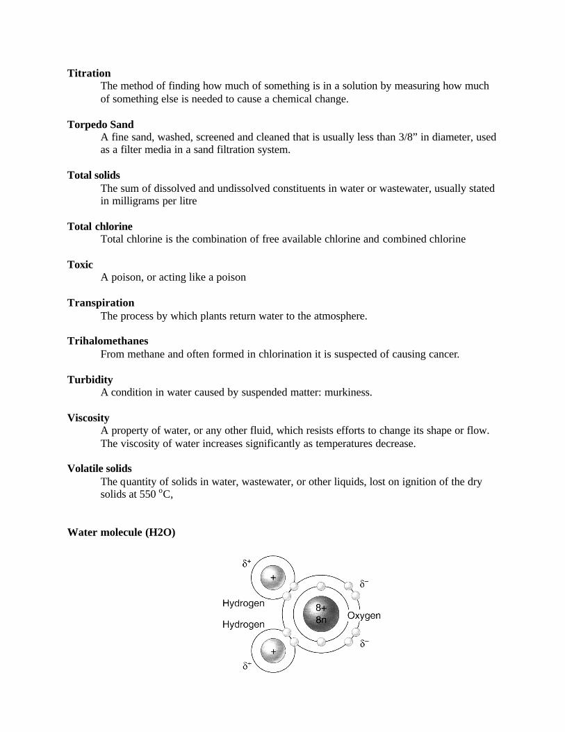
Titration The method of finding how much of something is in a solution by measuring how much of something else is needed to cause a chemical change.
Torpedo Sand
A fine sand, washed, screened and cleaned that is usually less than 3/8” in diameter, used as a filter media in a sand filtration system.
Total solids
The sum of dissolved and undissolved constituents in water or wastewater, usually stated in milligrams per litre
Total chlorine Total chlorine is the combination of free available chlorine and combined chlorine
Toxic A poison, or acting like a poison Transpiration
The process by which plants return water to the atmosphere. Trihalomethanes From methane and often formed in chlorination it is suspected of causing cancer. Turbidity
A condition in water caused by suspended matter: murkiness. Viscosity
A property of water, or any other fluid, which resists efforts to change its shape or flow. The viscosity of water increases significantly as temperatures decrease.
Volatile solids
The quantity of solids in water, wastewater, or other liquids, lost on ignition of the dry solids at 550 oC,
Water molecule (H2O)
Water hammer
Pressure waves caused by a rapid shift of flow velocity due to usually due rapid valve shutoff or opening. Characterized by a series of loud stutters in the pipes.
Watershed A closed area that collects precipitation runoff that drains into a particular body of water or watercourse.
Weir
A dam or enclosure in water or wastewater used to raise the water level or change the direction of its flow; with notches or a crest, it measures the flow.
ADDENDUM B MATH REVIEW & DOSAGE
EXAMPLES CHEMISTRY, SOLUTION &
PREPARATION
B - 1
MATH REVIEW & DOSAGE EXAMPLES INTRODUCTION The objective of this unit is to introduce the operator to the application of mathematics in solving problems related to the field of water treatment and to prepare him or her for further course work in the water treatment field. We will discuss the theoretical concepts of mathematics which form the basis for solving problems encountered in the operator's day to day work. Examples were written with the objective of showing by example how a typical problem is solved. To assist the student, a number of practice problems follow each section. For each question on the exercise sheet there is a corresponding example and practice problem for the operator to refer to for assistance in completing each lesson. For those students who are not comfortable with metric measurements, a brief explanation of the system and a set of conversion tables have been provided. A short review of basic geometry has also been included. It should be remembered and emphasized that the intent of this course is to allow the operator the opportunity to apply mathematical computations in solving water treatment problems and to improve his skills in mathematics.

B - 2
METRICS: Scientists and many other people throughout the world measure lengths, distance, area, volumes, weight, temperature and other values by a standard method called the metric system. There are two major systems of measurement in use, both related to one another. The English System and the Metric System. The English system of measurement developed from man's need to measure size and distances and were based on units that were a part of his body. For example, a "cubit" was the length of a man's forearm from his elbow to the tip of his middle finger. The Romans used the uncia for the width of a thumb and the English inch comes from this method. Twelve uncia equaled roughly the length of a man's foot and a man's foot was used to measure distance. The foot at first was the length of any man's foot. In some countries it was the length of the 'kings' foot. Measuring units based on a man's size failed because not all men were the same size, and as a result measurements varied from man to man. However, there was little need for standardization until man began to travel and trade with other men and some form of 'standard units' became necessary. Today one still finds different units in-use from one country to another. An example is the volume of a "gallon" by definition between Canada and the United states: 1.0 Imperial gallons = 1.2 U.S. gallons. Out of such confusion there developed a need for a simple standard system of measurement. In 1670 a French priest, Gabriel Mouton, developed a system of measurement using the decimal system. In 1790 the French National Assembly appointed a commission to study the measurement situation. This commission of French scientists proposed the metric system and in 1799 France adopted it as the legal system of weights and measures. In 1875 the "Treaty of the Metre" was signed to establish the General Conference on Weights and Measures which meets to determine the official definitions for units used in metric countries. In 1960 the present form was adopted and named the Systeme International d'Units or International System of Units more commonly known as SI. Since the early 1970' s both Canada and the United states have been working towards a changeover to the metric system. The popularity of the metric system stems from two characteristics, its simplicity and standardization. The metric system did not develop haphazardly nor did it use parts of the human body as units. In the metric system all units have a uniform scale based on the decimal system. The principal unit is the metre which is comparable to the yard as a unit of length. One meter is 39.37 inches or 1.093 yards long.
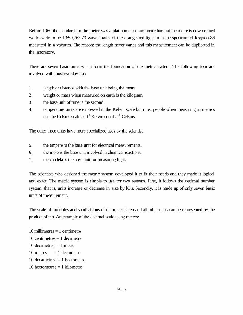
B - 3
Before 1960 the standard for the meter was a platinum- iridium meter bar, but the metre is now defined world-wide to be 1,650,763.73 wavelengths of the orange-red light from the spectrum of krypton-86 measured in a vacuum. The reason: the length never varies and this measurement can be duplicated in the laboratory. There are seven basic units which form the foundation of the metric system. The followlng four are involved with most everday use: 1. length or distance with the base unit belng the metre 2. weight or mass when measured on earth is the kilogram 3. the base unlt of time is the second 4. temperature units are expressed in the Kelvin scale but most people when measuring in metrics
use the Celsius scale as 1o Kelvin equals 1o Celsius. The other three units have more specialized uses by the scientist. 5. the ampere is the base unit for electrical measurements. 6. the mole is the base unit involved in chemical reactions. 7. the candela is the base unit for measuring light. The scientists who desiqned the metric system developed it to fit their needs and they made it logical and exact. The metric system is simple to use for two reasons. First, it follows the decimal number system, that is, units increase or decrease in size by lO's. Secondly, it is made up of only seven basic units of measurement. The scale of multiples and subdivisions of the meter is ten and all other units can be represented by the product of ten. An example of the decimal scale using meters: 10 millimetres = 1 centimetre 10 centimetres = 1 decimetre 10 decimetres = 1 metre 10 metres = 1 decametre 10 decametres = 1 hectometre 10 hectometres = 1 kilometre
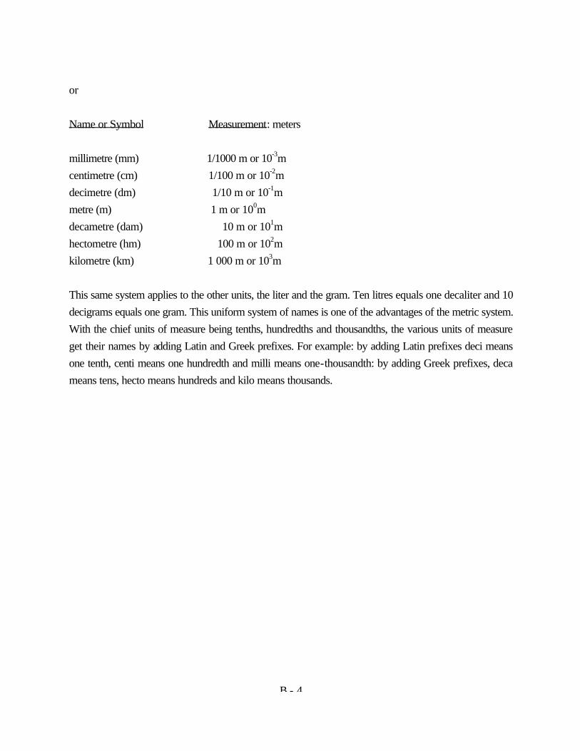
B - 4
or Name or Symbol Measurement: meters millimetre (mm) 1/1000 m or 10-3m centimetre (cm) 1/100 m or 10-2m decimetre (dm) 1/10 m or 10-1m metre (m) 1 m or 100m decametre (dam) 10 m or 101m hectometre (hm) 100 m or 102m kilometre (km) 1 000 m or 103m This same system applies to the other units, the liter and the gram. Ten litres equals one decaliter and 10 decigrams equals one gram. This uniform system of names is one of the advantages of the metric system. With the chief units of measure being tenths, hundredths and thousandths, the various units of measure get their names by adding Latin and Greek prefixes. For example: by adding Latin prefixes deci means one tenth, centi means one hundredth and milli means one-thousandth: by adding Greek prefixes, deca means tens, hecto means hundreds and kilo means thousands.
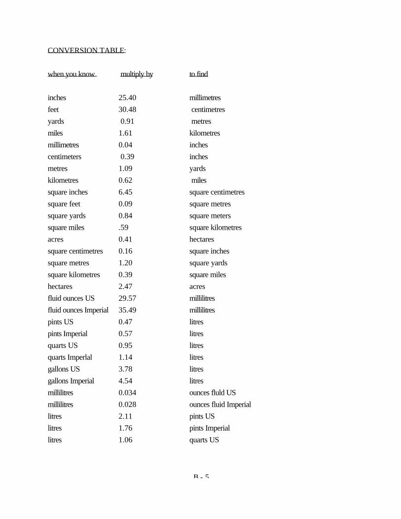
B - 5
CONVERSION TABLE: when you know multiply by to find inches 25.40 millimetres feet 30.48 centimetres yards 0.91 metres miles 1.61 kilometres millimetres 0.04 inches centimeters 0.39 inches metres 1.09 yards kilometres 0.62 miles square inches 6.45 square centimetres square feet 0.09 square metres square yards 0.84 square meters square miles .59 square kilometres acres 0.41 hectares square centimetres 0.16 square inches square metres 1.20 square yards square kilometres 0.39 square miles hectares 2.47 acres fluid ounces US 29.57 millilitres fluid ounces Imperial 35.49 millilitres pints US 0.47 litres pints Imperial 0.57 litres quarts US 0.95 litres quarts Imperlal 1.14 litres gallons US 3.78 litres gallons Imperial 4.54 litres millilitres 0.034 ounces fluld US millilitres 0.028 ounces fluid Imperial litres 2.11 pints US litres 1.76 pints Imperial litres 1.06 quarts US
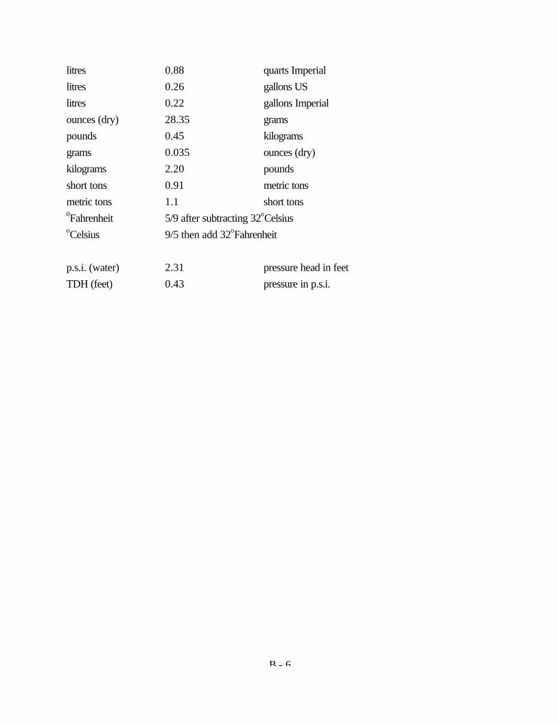
B - 6
litres 0.88 quarts Imperial litres 0.26 gallons US litres 0.22 gallons Imperial ounces (dry) 28.35 grams pounds 0.45 kilograms grams 0.035 ounces (dry) kilograms 2.20 pounds short tons 0.91 metric tons metric tons 1.1 short tons 0Fahrenheit 5/9 after subtracting 32oCelsius oCelsius 9/5 then add 32oFahrenheit p.s.i. (water) 2.31 pressure head in feet TDH (feet) 0.43 pressure in p.s.i.
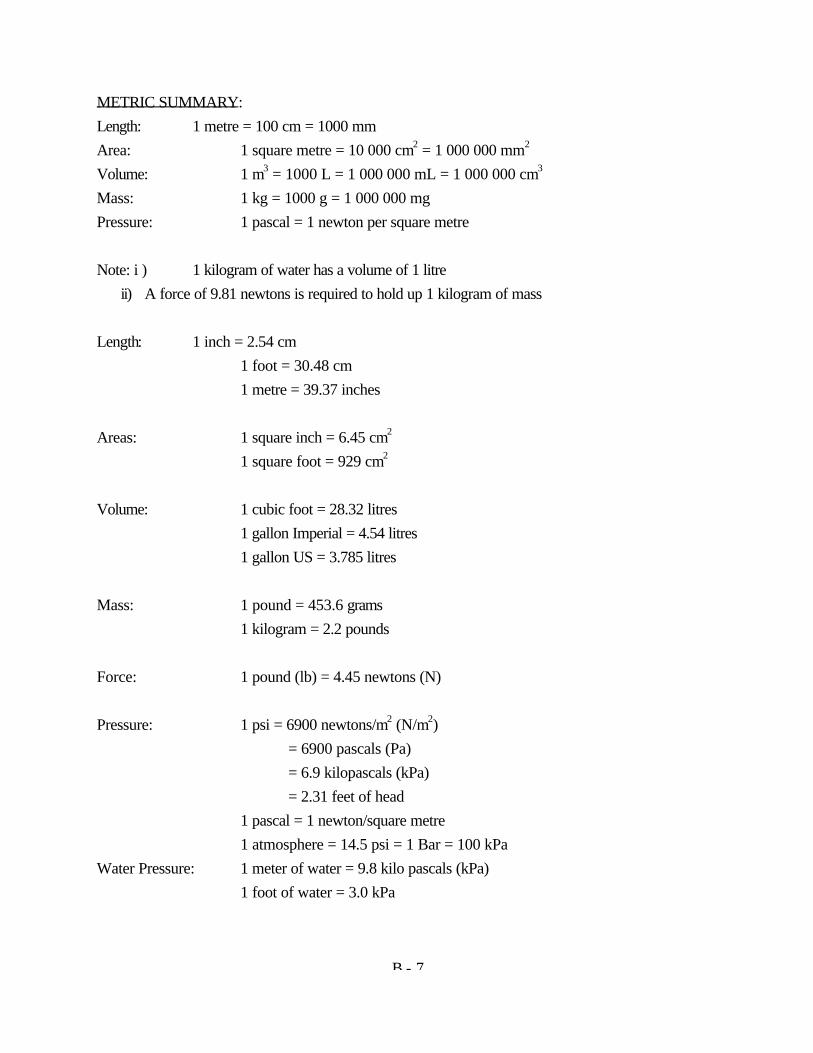
B - 7
METRIC SUMMARY: Length: 1 metre = 100 cm = 1000 mm Area: 1 square metre = 10 000 cm2 = 1 000 000 mm2 Volume: 1 m3 = 1000 L = 1 000 000 mL = 1 000 000 cm3 Mass: 1 kg = 1000 g = 1 000 000 mg Pressure: 1 pascal = 1 newton per square metre Note: i ) 1 kilogram of water has a volume of 1 litre ii) A force of 9.81 newtons is required to hold up 1 kilogram of mass Length: 1 inch = 2.54 cm 1 foot = 30.48 cm 1 metre = 39.37 inches Areas: 1 square inch = 6.45 cm2 1 square foot = 929 cm2 Volume: 1 cubic foot = 28.32 litres 1 gallon Imperial = 4.54 litres 1 gallon US = 3.785 litres Mass: 1 pound = 453.6 grams 1 kilogram = 2.2 pounds Force: 1 pound (lb) = 4.45 newtons (N) Pressure: 1 psi = 6900 newtons/m2 (N/m2) = 6900 pascals (Pa) = 6.9 kilopascals (kPa) = 2.31 feet of head 1 pascal = 1 newton/square metre 1 atmosphere = 14.5 psi = 1 Bar = 100 kPa Water Pressure: 1 meter of water = 9.8 kilo pascals (kPa) 1 foot of water = 3.0 kPa
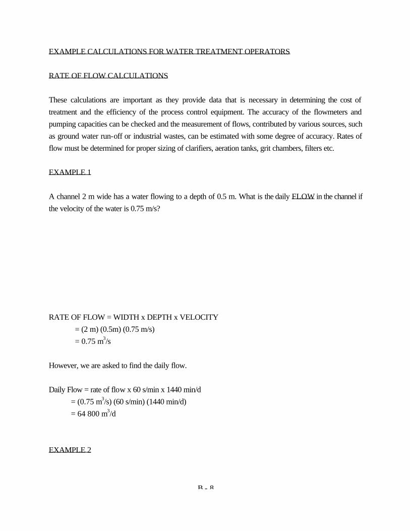
B - 8
EXAMPLE CALCULATIONS FOR WATER TREATMENT OPERATORS RATE OF FLOW CALCULATIONS These calculations are important as they provide data that is necessary in determining the cost of treatment and the efficiency of the process control equipment. The accuracy of the flowmeters and pumping capacities can be checked and the measurement of flows, contributed by various sources, such as ground water run-off or industrial wastes, can be estimated with some degree of accuracy. Rates of flow must be determined for proper sizing of clarifiers, aeration tanks, grit chambers, filters etc. EXAMPLE 1 A channel 2 m wide has a water flowing to a depth of 0.5 m. What is the daily FLOW in the channel if the velocity of the water is 0.75 m/s? RATE OF FLOW = WIDTH x DEPTH x VELOCITY = (2 m) (0.5m) (0.75 m/s) = 0.75 m3/s However, we are asked to find the daily flow. Daily Flow = rate of flow x 60 s/min x 1440 min/d = (0.75 m3/s) (60 s/min) (1440 min/d) = 64 800 m3/d EXAMPLE 2
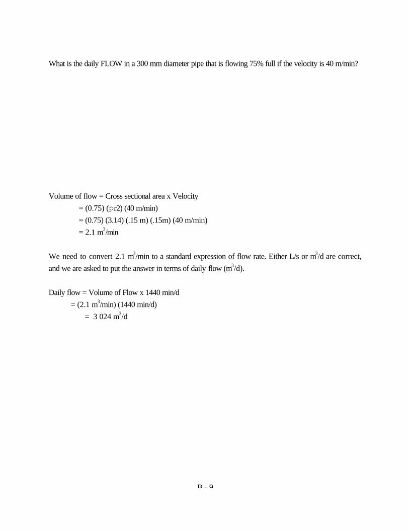
B - 9
What is the daily FLOW in a 300 mm diameter pipe that is flowing 75% full if the velocity is 40 m/min? Volume of flow = Cross sectional area x Velocity = (0.75) (pr2) (40 m/min) = (0.75) (3.14) (.15 m) (.15m) (40 m/min) = 2.1 m3/min We need to convert 2.1 m3/min to a standard expression of flow rate. Either L/s or m3/d are correct, and we are asked to put the answer in terms of daily flow (m3/d). Daily flow = Volume of Flow x 1440 min/d = (2.1 m3/min) (1440 min/d) = 3 024 m3/d
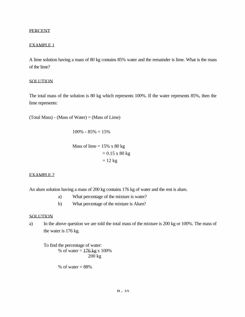
B - 10
PERCENT EXAMPLE 1 A lime solution having a mass of 80 kg contains 85% water and the remainder is lime. What is the mass of the lime? SOLUTION The total mass of the solution is 80 kg which represents 100%. If the water represents 85%, then the lime represents: (Total Mass) - (Mass of Water) = (Mass of Lime) 100% - 85% = 15% Mass of lime = 15% x 80 kg = 0.15 x 80 kg = 12 kg EXAMPLE 2 An alum solution having a mass of 200 kg contains 176 kg of water and the rest is alum. a) What percentage of the mixture is water? b) What percentage of the mixture is Alum? SOLUTION a) In the above question we are told the total mass of the mixture is 200 kg or 100%. The mass of
the water is 176 kg. To find the percentage of water: % of water = 176 kg x 100% 200 kg % of water = 88%
B - 11
b) If 88% of the mixture is water then; Total Mass - Mass of Water = Mass of Alum 100% - 88% = 12% DETENTION TIME The concept of detention time is used in conjunction with many treatment plant processes. "DETENTION TIME" refers to the length of time a drop of water or a suspended particle remains in a tank or chamber. Detention time may also be thought of as the number of minutes or hours required for each tank to fill and overflow. The mental image might be one of the flow from the time water enters the tank until it leaves the tank completely , as shown in the following figure. This process is also known as "plug flow". EXAMPLE A sedimentation tank has a capacity of 132 m3. If the hourly flow to the clarifier is 47 m3/h, what is the detention time? Since the flow rate is expressed in hours, the detention time calculated is also in hours: Detention time = Volume of tank Flow rate = 132 m3 47 m3/h = 2.8 h WEIR OVERFLOW RATE
B - 12
The calculation of WEIR OVERFLOW RATE is important in detecting high velocities near the weir, which adversely affect the efficiency of the sedimentation process. With excessively high velocities, the settling solids are pulled over the weirs and into the effluent troughs. In calculating the weir overflow rate, you will be concerned with the litres per second flowing over each metre of weir length. The following figures can be associated with weir overflow rate in rectangular and circular sedimentation basins. Since weir overflow rate is L/s flow over each m of weir length, the corresponding mathematical equation is: Weir overflow rate = flow (L/s) weir length (m) EXAMPLE 1 If a sedimentation tank has a total of 27 m of weir over which the water flows, what is the weir overflow rate when the flow is 90 L/s? Weir overflow rate = flow (L/s) weir length (m) = 90 L/s
B - 13
27 m = 3.3 L/s m EXAMPLE 2 A circular clarifier receives a flow of 16 416 m3/d. If the diameter is 24 m, what is the weir overflow rate? Before you can calculate the weir overflow rate, you must know the total length of the weir. The relationship of the diameter and circumference of a circle is the key to determining this problem. Circumference = 3.14 x Diameter In this problem, the diameter is 24 m. Therefore, the length of weir (circumference) is Circumference = (p) (Diameter) = (3.14) (24 m) = 75.4 m We now must convert m3/d to L/s by the following: m3/d x 1 000 L = L/s s/d m3 16 416 m3/d x 1 000 L = 190 L/s 86 400 s/d m3
Now solve for the weir overflow rate:
B - 14
Weir overflow rate = flow (L/s) weir length (m) = 190 L/s 75.4 m = 2.5 L/s m PUMPING RATES The rate of flow produced by a pump is expressed as the volume of water pumped during a given period of time. The mathematical equation used in pumping rate problems can usually be determined from the verbal statement of the problem. VERBAL: What is the pumping rate in m3 per day? MATH: pumping rate = m VERBAL: What is the pumping rate in litres per second? MATH: pumping rate = L The volume pumped during a period can be determined either by a flowmeter or by measuring the volume being pumped into or out of a tank. Most pumping rate problems will ask you to give an answer in one form (L/s) and will give you the information in another form (m/d). At first the conversion between these two expressions looks difficult, but once you become familiar with their relationship to each other, converting is simple. Here is the proof. m3/d = m3 x 1 000 L = L or L/s 86 400 s/d s m3 s or conversely L - 1 000 L = m3 x 86 400s = m3 or m3/d s m3 s d d
B - 15
EXAMPLE An empty rectangular tank 8 m long and 6 m wide can hold water to a depth of 2 m. If this tank is filled by a pump in 55 min. What is the pumping rate in litres per second? In this example, the entire tank was filled during the 55 min pumping test. Therefore the total volume pumped is equal to the capacity of the tank in m . Volume of Tank = Area of Rectangle x Depth = (8 m) (6 m) (2 m) = 96 m3 To find L/s we convert 96 m3 to litres and 55 min to seconds. 96 m3 x 1 000 L = 96 000 L m3 55 min x 60 s = 3 300 s min Then we divide: 96 000 L = 29.1 L/s 3 300 s 29.1 L/S is the answer to the first part of the question. To find the answer to the second part, we must convert L/s to m /d. 29.1 L - 1 000 L x 86 400 s = 2 514 m3/d s m3 d 2 514 m3/d is the answer to the second part of the question.
B - 16
DENSITY For scientific and technical purposes, the DENSITY of a body of material is precisely defined as the mass PER UNIT OF VOLUME. The density of dry materials, such as sand, activated carbon, lime and liquids such as water, liquid alum or liquid chlorine can be expressed as g/cm3. The density of gases, such as air, chlorine, methane or carbon dioxide is normally expressed in g/L. The density of a substance CHANGES SLIGHTLY AS THE TEMPERATURE OF THE SUBSTANCE CHANGES. This happens because substances usually increase in volume as they become warmer, as illustrated in Figure 1. Because of the expansion with warming, the mass is spread over a larger volume, so the density is less when a substance is warm than when it is cold. Similarly, a change in pressure will change the volume occupied by a substance. As a result, DENSITY VARIES WITH PRESSURE, increasing as pressure increases and decreasing as pressure decreases (Figure 2). The effects of pressure and temperature on solids and liquids, are very small and are usually ignored. However, temperature and pressure have a significant effect on the density of gases and whenever the density of a gas is given, then the temperature and pressure at that density are usually also given. RELATIVE DENSITY (Specific Gravity) Although there may be many numbers that express the density of the same substance (depending on the unit used) there is only one relative density associated with each substance (for one particular temperature and pressure). The relative density of a substance is compared against a "Standard" density. RELATIVE DENSITY OF SOLIDS & LIQUIDS The standard density used for solids and liquids is that of water, which is one g/cm at 4 degrees C and a pressure of 101.3 kN/m or kilopascals (kPa), the pressure of the atmosphere at sea level. Therefore,
B - 17
the relative density of a solid or liquid is the density of that solid or liquid COMPARED TO THE DENSITY OF WATER. It is the ratio of the density of that substance to the density of water. Let's look at an example. The density of SAE 30 motor oil is Relative Density = oil 0.9 g/cm3 water 1.0 g/cm3 = 0.90 In other words, relative density in this example tells you that oil is only 9/10 as dense as water. Because a cm3 of oil has a mass less than a cm3 of water, oil floats on the surface of water. Relative Density of Gases The relative density of a gas is usually determined by comparing the density of the gas with the density of air, which is 1.2 g/L at a temperature of 20 degrees C and a pressure of 101.3 (kN/m) or kilopascals (kPa) the pressure of the atmosphere at sea level. For example, the density of chlorine gas is 2.99 g/L . Its relative density would be calculated as follows: Relative Density = Cl2 2.99 g/L = 2.49 air 1.2 g/L This tells you that chlorine gas is approximately 2.5 times as dense as air. Therefore, when chlorine gas is introduced into a room it will concentrate at the bottom of the room. This is important to know since chlorine is a deadly toxic gas. DOSAGE CALCULATIONS It is most necessary for a plant operator to know how to calculate the dosages of the various chemicals used in water treatment. It is important to be accurate when calculating dosages as too little chemical
B - 18
may be ineffective and too much a waste of money. In process control the exact dose of chemical must be determined through calculation for the purposes of efficient operation and economy. EXAMPLE 1 The chlorine dosage of an effluent is 15 mg/L. How many kilograms of chlorine will be required to dose a flow of 8 500 m3/d? In this question, it will be necessary to utilize your knowledge of the metric system. 1 mg/L = 1 kg/l 000 m3 For every 1 000 m3 of water of flow, we will need to use 15 kg chlorine. 15 kg Cl2 x 8 500 m3/d = 127.5 kg C12/d 1 000 m3 Above we expressed 15 mg/L as 15 kg Cl2 /1 000 m3 and multiplied it by the flow to obtain the answer expressed as 127.5 kg C12/d EXAMPLE 2: A chlorinator is set to feed a 94.8 kg/d of chlorine. If the average daily flow through the plant is 7 900 m3/d, what is the DAILY AVERAGE CHLORINE DOSAGE IN MG/L? We know that 1 mg/L = 1 kg 1 000 m3 We are told we use 94.8 kg chlorine for every 7900 m3 water. 94.8 kg Cl2/d = 12 kg Cl2 = 12 mg/L 7.9 x 1 000 m3/d 1 000 m3 Above we divided the mass of chlorine used per day by the flow expressed in 1 000 m per day and
B - 19
found we used 12 kg Cl2 for every 1 000 m of flow or 12 mg/L. HYPOCHLORINATION CALCULATIONS Definition - Hypochlorination is the application of hypochlorite ( a compound of chlorine and
another chemical), usually in the form of solution, for disinfection purposes. EXAMPLE 1 The treated product at a water treatment plant requires a chlorine dosage of 98 kg/d for disinfection purposes. If we are using a solution of hypochlorite containing 60% available chlorine, how many kg/d hypochlorite will be required? SOLUTION We are told in the problem that 60% of the hypochlorite is available chlorine which is the portion of the solution capable of disinfecting. Solving the equation we have; kg/d hypochlorite = 98 kg/d of chlorine needed 0.6 available chlorine in sol'n = 163.3 kg/d hypochlorite solution EXAMPLE 2 A hypochlorite solution contains 5% available chlorine. If 4 kg of available chlorine are needed to disinfect a watermain, how much 5% solution would be required?
B - 20
We are told 4 kg of chlorine will do the job of disinfection. By a 5% solution we mean that 5% by mass of the solution is to be made up of chlorine. So 100 kg of 5% hypochlorite solution will contain 5 kg chlorine. Using the formula for ratios A = C B D we substitute: 5 kg chlorine = 4 kg chlorine required 100 kg sol'n ? kg sol'n required Since D = C x B = 4 kg x 100 kg = 80 kg solution A 5 kg CHEMICAL FEEDING Solution Preparation - Jar Tests Jar tests are used to determine correct chemical dosages for such chemicals as alum, ferric chloride and polymers. These are chemicals utilized in water treatment facilities for coagulation and flocculation of colloidal particles. The jar test simulates, on a small scale, the activities going on in various sections of the full scale treatment process. Varying amounts of the chemicals are compared against each other to find out which chemical and dosage best accomplishes the desired results. Stock solutions of coagulants, coagulant aids and other chemicals, should be prepared at concentrations such that quantities suitable for use in the jar tests can be measured accurately and conveniently. If one is dealing with dry chemicals the preparation of these stock solutions is straight forward. For example to prepare a 1 g/L stock solution using dry chemicals, 1 gram of the chemical is made up to 1 000 mL with water. However, with concentrated liquid solutions a dilution step is required. Any dilution step must take into account the relative density of the solution being diluted. For example, if one has a 48.5% alum solution with a relative density of 1.35 and wishes to make up a 1 g/L stock solution the following procedure should be followed: 1 mL 48.5% liquid alum has a mass of 1.35 g
B - 21
1 mL contains 1.35 g x 48.5 = 0.65 g alum 100 so 1.54 mL of the sol'n will contain 1 g Alum Therefore, add 1.54 mL liquid alum to water and make up to 1 000 mL for a 1 g/L stock solution. 1 g/L solutions are easy to use because 1 mL of solution has a mass of 1 mg. After jar tests have been carried out the type of chemical dosage and point of application best suited to the characteristics of the water or sewage to be treated should easily be established. The next step is to feed the chemical to be used at the dosage determined in the jar tests into the full scale treatment facility. The operator is faced with using a dry or liquid chemical which will be fed into the process by means of a dry or liquid chemical feeder. If feeding dry chemicals, the feeder will be calibrated, most likely, in grams per minute or, if liquid chemicals are being utilized, in millilitres per minute. Following is a detailed approach to establishing feed rates for chemicals. EXAMPLE Given a daily flow rate of 16 000 m3/d and an alum dosage of 13 mg/L, what is the alum flow rate in g/min? Step 1 Determine kg/d of Alum required. 1. Alum dosage of 13 mg/L = 13 kg 1 000 m3 2. Feed Rate = Dosage x Flow = 13 kg x 16 000 m3 1 000 m3 d = 208 kg/d of alum
B - 22
Step 2 We are asked to give the flow rate in g/min 1. Convert kg/d to g/d. Since 1 kg = 1 000 g 208 kg = 208 000 g d d 2. Convert kg/d to g/min. Since 1 day is equivalent to 1 440 min (24 h x 60 min) 208 000g/d = 144.4 g/min 1 440 min/d EXERCISE 1 1. Calculate the surface area of a rectangular settling tank 18 m long and 4m wide. 2. Calculate the surface area of a circular sand filter with a diameter of 15m. 3. Calculate the volume of a raw water intake crib 8 m long, 3 m wide and 6m deep. 4. What is the volume of a circular storage tank that is 7 m in diameter and 15m high? 5. What is the volume of water contained in 84 m of pipe with an inside diameter of 10 cm: a) in m3? b) in L? 6. If a pump delivers 1.44 m3 in 20 minutes, what is the pumping rate in: a) L/s? b) m3/d? 7. How many m3 of water will a 5 L/s pump deliver in 5 minutes? 8. A 12 m3 storage tank supplies alum for coagulation at a rate of 330 mL/min. How often will the
B - 23
tank need to be refilled? 9. The prechlorination chamber at a water treatment plant has a volume of 225m3. If the flow rate
from the tank is 11 L/s, what is the average detention time in hours? 10. How many kg of chlorine are required to treat 18 000 m3 of water per day with chlorine at 5.0
mg/L? 11. A gas chlorinator treats 2 700 m3 with 2 kg of chlorine per day. Calculate the dosage rate. The
residual is measured at 0.27 mg/L. What is the chlorine demand: a) in mg/L? b) in kg/d? 12. In the chart below determine the mass of chemical in kg that will be required to feed at the rate
indicated along the top of the chart in relationship to the volume of water flowing as indicated down the side.
B - 24
13. In the chart below determine the dosage in mg/L that will coincide with the flow indicated on the vertical scale and the mass of alum on the horizontal scale.
14. A liquid solution with a total mass of 97 kg contains 84 kg of water and the remainder is alum. a) What percentage of the solution is water? b) What percentage of the solution is alum? 15. A mixture of water and powdered carbon is to be 85% water. If the total volume required is
3.6 m3, what is the mass of the carbon? 16. A hypochlorite solution contains 12% available chlorine. If 3 kg of available chlorine are needed

B - 25
to disinfect a main: a) how many kg of solution are required? b) how many litres of solution are required?
B - 26
FILTER LOADING RATE The "filter loading rate" is expressed as L or m3 of water applied to each m2 of surface area. This could also be described as the amount of water flowing down through each m2 of filter surface. Filter design loading rates are expressed as L/s/m2. Filter loading rate = m3/d Flow x 24 h m2 Filter Area d NOTE: Design loading rates for filters are expressed in US gals at present. Using
conversion factors to obtain S.I. units is necessary when studying American designed filters. Typical loading rates are shown below:
Rapid sand filter = 1.36 L/s/m2, (2 US gpm/ft2) Dual Media = 0.136 - 0.272 L/s/m2, (0.2 - 0.4 US gpm/ft2) Multi Media = 3.41 - 6.82 L/s/m2 , (5 - 10 US gpm/ft2) EXAMPLE A rapid sand filter is 10 m wide and 15 m long. If the flow through the filter is 17 630 m3/d what is the filter loading rate in L/s/m2 ? First, convert the flow to L/s 17 630 m3 x 1 000 L ÷ 86 400 s = 204 L d m d s Then express the filter loading rate mathematically as: Filter loading rate = flow filter area = 204 Ls 150 m2 = 1.36 L/s/m2
B - 27
FILTER BACKWASH RATE There are two methods that may be used to calculate the filter backwash rate. a) Filter Backwash Rate = flow L/s filter area m2 b) Filter Backwash Rate = meters of water rise hour NOTE: As with filter loading rates, filter backwash rates are also expressed in U.S. gals at present.
Rates are shown below: Minimum = 10.2 L/s/m2, (15 US gpm/ft2) Maximum = 15.3 L/ms/m2, (22.5 US gpm/ft2) This is equivalent to a rise in the water level of 36.67 m/h (2 ft/min) to 55.0 m/h (3 ft/min). EXAMPLE 1 A rapid sand filter is 10 m wide and 12 m long. If backwash water is flowing upward at a rate of 1.56 m /s, what is the backwash rate in L/s/m2 ? Flow = 1.56 m3 x 1 000 L s m2 = 1 560 L/s Therefore, there are 1 560 L/s flowing upward through a filter with a surface area of 120 m . This can be written mathematically as: Filter backwash rate = flow filter area
B - 28
= 1 560 L/s 120 m2 = 13 L/s/m2 EXAMPLE 2 A mixed-media filter is 8 m wide and 11 m long. If the filter receives a backwash flow of 84 000 m3/d, what is the filter backwash flow rate in L/s/m2 ? As in the last example, first convert the backwash flow to L/s. 84 000 m3 x 1 000 L ÷ 86 400 s = 972.22 L d m3 d s Filter backwash rate = flow filter area = 972.22 L/s (8 m) (11 m) = 972.2 L/s 88 m2 = 11.05 L/s/m2 Filter backwash rates, as noted earlier, are sometimes expressed in terms of vertical rise of water in a time interval measured in hours, for example, metres per hour (m/h). The units of measure are directly related to each other as shown by the following proof: = 11.05 L/m x 3 600 s ÷ 1 000 L s h m3 = 39.672 m3/m2 h = 39.672 m/h For simplification, a conversion factor can be extracted from the above proof. 3 600 s ÷ 1 000 L h m3
B - 29
= 3.6 s/m3/h/L Then by substitution back into the proof: 11.05 L/m2 x 3.6 s/m3 = 39.672 m3/m2 s h/L h = 39.672 m/h EXERCISE 2 1. A rapid sand filter is 5 m wide and 10 m long. If the backwash water flow rate is 55 600 m3,
determine the filter backwash rate in m/h? 2. What is the filter backwash rate in L/s/m2 corresponding to a filter backwash rate of 37 m/h? 3. During the operation of a multi media sand filter, the operator measured the flow rate to be 14.4
m/h. Express this flow rate in L/s/m2 ?
B - 30
4. A rapid sand filter system is 4 m wide and 7 m long. If the flow through the filter is 3 300 m3/d
what is the filter loading rate: a) in L/s/m2? b) in m/h? Chemical Feeding & Preparation of Stock Solutions SOLUTIONS A solution consists of two components, a solvent which is the dissolving medium and a solute which is the substance dissolved. The solute is dispersed as molecules and ions and the distribution of the solute is homogenous throughout the solution. A common example of solvent and solute is water and sugar. A concentrated solution is one which contains a relatively large amount of solute per unit volume of solution. A dilute solution is one which contains a relatively small amount of solute per unit volume of solution. The words "strong" and "weak" should not be used when referring to the concentration of a solution. Strong and weak are terms that are more properly used to describe the chemical activity of a substance. Solution Preparation - Jar Tests Jar tests are used to determine correct chemical dosages for such chemicals as alum or polymers. These chemicals are utilized in water treatment for coagulation and flocculation of colloidal particles. The jar test simulates, on a small scale, the activities going on in the full scale treatment process. Varying amounts of the chemicals are compared to each other to see which chemical and dosage, best accomplishes the desired results. Stock solutions of coagulants, coagulant aids and other chemicals, should be prepared at concentrations such that quantities suitable for use in the jar tests can be measured accurately and conveniently. When making stock solutions from dry chemicals, a very straight forward approach is used. Dissolve 1
B - 31
gram of solute in 1 litre of water to obtain a 1 g/L solution. Using the solution is easy because 1 gram of solute is contained in 1 litre solvent; therefore 1 mg of solute is contained in 1 mL of solvent. When a jar test requires dosages of solution, simply fill a pipet to the required dosage and the proper mass of chemical will be present in the contained volume of the solution. EXAMPLE: One gram of soda ash is contained in one litre of distilled water. We now have a 1 g/L solution of soda ash. A jar test requires dosages of 5 mg/L, 10 mg/L, 15 mg/L, 20 mg/L, 25 mg/L and one jar is a blank. How many mL of soda ash solution are required for each dosage? 1 g/L soda ash solution = 1 mg of soda ash/mL of solution 5 mg of soda ash / 5 mL of solution Req'd dosages = 5 mg/L, 10 mg/L 15 mg/L, 20 mg/L, 25 mg/L mL of solution = 5 mL, 10 mL, 15mL, 20 mL, 25 mL Remember that the dosage is being added to 1 litre of raw water so now the dosage is expressed as 5 mg of soda ash/L of raw water. Conveniently 5 mg/L, and so on for each of the other required dosages. When preparing solutions from liquid concentrates, the amount of chemical present in the solution needs to be known as well as the relative density of the original solution. The concentration and relative density are usually found on the product label. A concentrated alum solution contains 48.5% alum and has a relative density of 1.35. To prepare a 1 g/L solution from the concentrated alum, we need to find out how many mL of concentrate contains 1 gram of pure alum. 1 mL of concentrated = 1.35 x 0.485 g of alum solution contains = 0.65 g of alum
B - 32
Then the volume occupied of 1 g of alum is: = 1 g 0.65 g/mL = 1.54 mL 1.54 mL of concentrated alum contains 1 gram of alum. To make a 1 g/L solution of alum simply dilute l.54 mL of concentrated solution to one litre with distilled water. Dosages can now be applied to jar tests as described earlier. EXAMPLE A water plant with a daily flow of 1 700 m3 doses at 55 mg/L with a 48.5% liquid alum solution. What is the feed rate in mL/min? Data: Flow 1.7 x 1000 m3/d 48.5% alum by mass as active ingredient 1.34 g/cm3 relative density mass of sol'n req'd = (55 kg/l 000 m3) (1.7 x 1000 m3/d) 0.485 = 192.8 kg/d volume of sol'n = 192.8 kg/d 1.34 kg/L = 143.9 L/d Flow Rate = 143.9 L x 1 000 mL ÷ 1 440 min d L d = 99.9 mL/min It is important to mention that feed rates are properly expressed as mL/s but using mL/min is convenient
B - 33
to calibrate and measure. To obtain mL/s simply divide mL/min by 60 s/min as shown with the above example. Flow rate = 99.9 mL - 60 s min min = 1.665 mL/s CALCULATION OF FEED RATES USING A FORMULA An alternate method of calculating feed rates in mL/min is through the use of a formula that takes into account all variables such as chemical concentrations, optimum dosages, plant flow, etc. Below is a mathematical method for determining feed rates of chemical addition in millilitres per minute (mL/min), the normal units found on most liquid chemical feeders. These units of feed rate are utilized as they provide a convenient volume and time scale for calibration and accurate feeding of highly expensive and sometimes hazardous chemicals. The formula takes into account variations in concentrations of chemicals and their relative densities. Once proper dosage has been established through jar tests and daily flows from the flow chart and the variations in the chemical's composition from the delivery tag this formula will provide the correct feed rate in millilitres per minute. FEED RATE FORMULA (mL/min) mL/min = (Dosage mg/L) (flow/l 000 m3/d) (1 000 mL/L) % active chemical x relative x 1 400 min/d as decimal fraction density This formula contains conversion factors that are constants. These are indicated by the boxes in the formula. For ease of calculation, we can reduce the two conversion factors to one. The constant would

B - 34
be: 1 000 mL/L = 0.694 1 440 min/d As a result, we can simplify the feed rate formula. Using the previous example, determination of the alum feed rate, the calculation can be shown as: mL/min = (Dosage mg/L) (Flow/l 000 m3/d) (0.694) % active chemical x Relative as a decimal fraction Density = (55 mg/L) (1.7 x 1 000 m3/d) (0.694) (0.485) (1.34 kg/L) = 99.8 mL/min
B - 35
EXERCISE 3 1. How many mL of alum are needed to prepare 1 000 mL of a 1 g/L solution of alum if the
concentrated solution is 42.3% by mass and the relative density is 1.42? 2. How many mL of alum are required to make up 1 L of a 1 g/L solution for jar tests if the alum is
48% by mass and the relative density is 1.34? 3. In a water treatment plant both alum and activated silica are being used in the coagulation stage
to help precipitate the colloidal suspensions. Jar tests indicated that 50 mg/L alum and 5.5 mg/L activated silica is the optimum dosage. Calculate, using the formula, the feed rate needed for each chemical in mL/min.
DATA: Flow 1 000 m3/d Liquid Alum Relative Density 1.35 kg/L Liquid Alum contains 48.5% Al2(SO4)3 °14 H2O Activated Silica Rel. Dens. 1 kg/L Activated Silica contains 1% solution 4. The dry alum dosage rate is 12 mg/L at a water treatment plant. The flow rate at this plant is 13
500 m3/d. How many kilograms per day of alum are required?
B -38
CHEMISTRY, SOLUTION & PREPARATION SUBJECT: BASIC CHEMICAL PRINCIPLES OBJECTIVES: The Student will be able to: 1. Select the correct definition from a given list for each of the following items: a. electron b. proton c. neutron d. atom e. element f. compound g. valence 2. Select the examples from a given list to indicate the following terms: a. ion i) anion ii) cation b. radical c. organic compound d. inorganic compound 3. Calculate molecular weight for specified compounds given a list of atomic weights. 4. Select from a given list, the correct name for a given simple compound.
B -39
BASIC CHEMICAL PRINCIPLES CHEMISTRY Chemistry might be defined as the science that deals with the composition, properties and changes undergone by matter under certain influences. MATTER Matter is defined as anything that occupies space and has mass. The page these words are written on is a form of matter, as is the ink which forms the letters on the page. Some forms of matter consist of a single kind of matter called a pure substance. ATOMS Pure substances are made up of one or more "atoms". An atom might be defined as the smallest particle we could separate which would still exhibit the characteristic properties of that pure substance. Pure substances can be either "elements" or "compounds". Elements are Pure Substances which contain only one kind of atom, whereas compounds are pure substances which contain more than one kind of atom. Examples of common elements are gold (Au), chlorine (Cl), sulphur (S), oxygen (O) and hydrogen (H). Examples of common compounds are sodium chloride (NaCl), water (H2O), hydrogen sulphide (H2S) and calcium hydroxide (CaOH). ELEMENTS
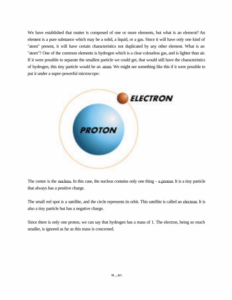
B -40
We have established that matter is composed of one or more elements, but what is an element? An element is a pure substance which may be a solid, a liquid, or a gas. Since it will have only one kind of "atom" present, it will have certain characteristics not duplicated by any other element. What is an "atom"? One of the common elements is hydrogen which is a clear colourless gas, and is lighter than air. If it were possible to separate the smallest particle we could get, that would still have the characteristics of hydrogen, this tiny particle would be an atom. We might see something like this if it were possible to put it under a super-powerful microscope:
The centre is the nucleus. In this case, the nucleus contains only one thing - a proton. It is a tiny particle that always has a positive charge. The small red spot is a satellite, and the circle represents its orbit. This satellite is called an electron. It is also a tiny particle but has a negative charge. Since there is only one proton, we can say that hydrogen has a mass of 1. The electron, being so much smaller, is ignored as far as this mass is concerned.
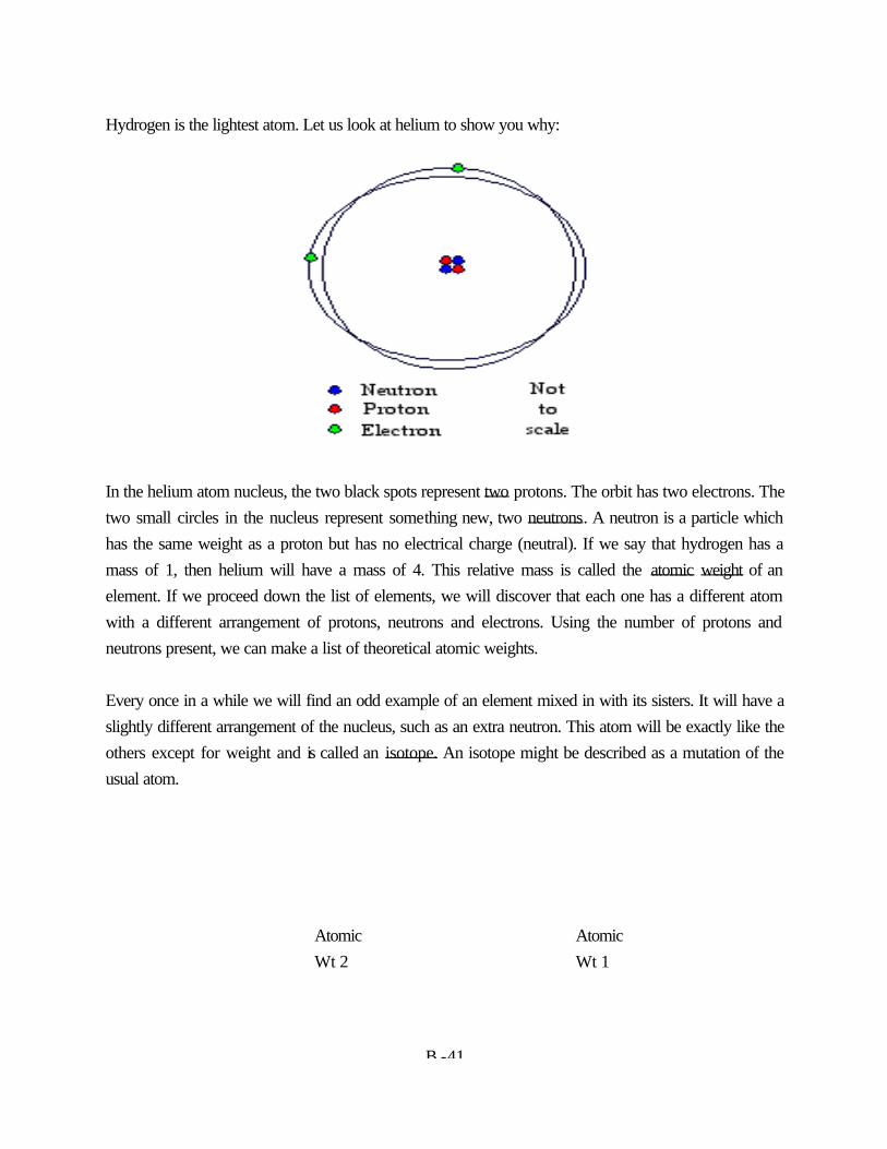
B -41
Hydrogen is the lightest atom. Let us look at helium to show you why:
In the helium atom nucleus, the two black spots represent two protons. The orbit has two electrons. The two small circles in the nucleus represent something new, two neutrons. A neutron is a particle which has the same weight as a proton but has no electrical charge (neutral). If we say that hydrogen has a mass of 1, then helium will have a mass of 4. This relative mass is called the atomic weight of an element. If we proceed down the list of elements, we will discover that each one has a different atom with a different arrangement of protons, neutrons and electrons. Using the number of protons and neutrons present, we can make a list of theoretical atomic weights. Every once in a while we will find an odd example of an element mixed in with its sisters. It will have a slightly different arrangement of the nucleus, such as an extra neutron. This atom will be exactly like the others except for weight and is called an isotope. An isotope might be described as a mutation of the usual atom. Atomic Atomic Wt 2 Wt 1
B -42
Hydrogen "Heavy" Hydrogen (an isotope) If we could take a quantity of hydrogen atoms and weigh them, we would find that the average weight is not 1 but 1.008 due to the occasional presence of the heavier isotope. This explains why atomic weights are not all even numbers. If you will turn to the accompanying table cataloguing the distribution of electrons in each orbit around the nucleus (Table 1-2), you will see that each orbit has only so many "parking spots" and once these are occupied, a new orbit shell is begun. An exception to this occurs in some of the outermost orbits where some "double parking" is overlooked. In any case, there are never more than 8 electrons in the outer-most shell. On the basis of the distribution of electrons we can isolate four different structural types of atoms: 1. Inert elements - these with all orbit shells filled to the maximum. 2. Simple elements - those with only one unfilled shell. 3. Transition elements - those with two unfilled shells. 4. Rare earth elements - those with three unfilled shells. You will notice that the elements are arranged in the table in order by their atomic number. This is nothing more than the sum of the number of electrons in the shells surrounding the nucleus. Each element differs from its immediate neighbours by one electron and therefore one proton in the nucleus (since all elements must be electrically neutral).
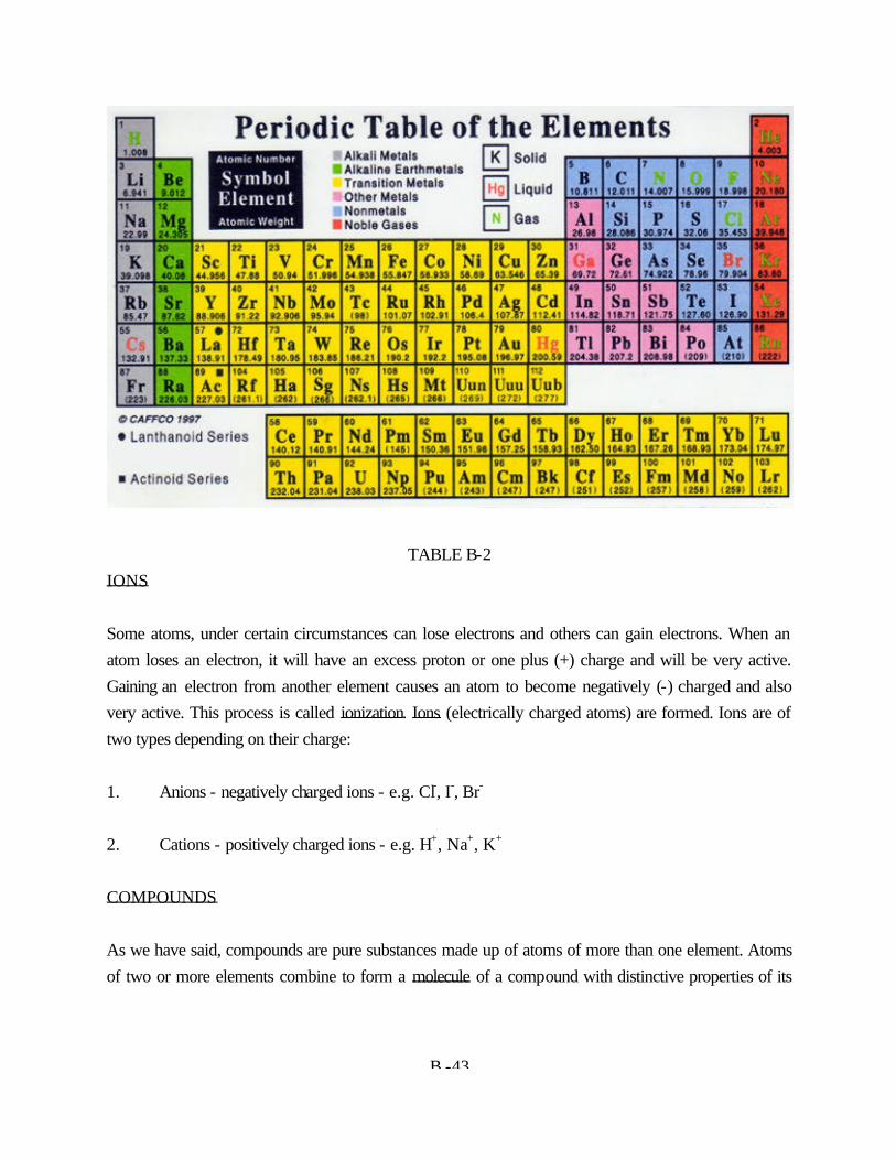
B -43
TABLE B-2 IONS Some atoms, under certain circumstances can lose electrons and others can gain electrons. When an atom loses an electron, it will have an excess proton or one plus (+) charge and will be very active. Gaining an electron from another element causes an atom to become negatively (-) charged and also very active. This process is called ionization. Ions (electrically charged atoms) are formed. Ions are of two types depending on their charge: 1. Anions - negatively charged ions - e.g. Cl-, I-, Br- 2. Cations - positively charged ions - e.g. H+, Na+, K+ COMPOUNDS As we have said, compounds are pure substances made up of atoms of more than one element. Atoms of two or more elements combine to form a molecule of a compound with distinctive properties of its
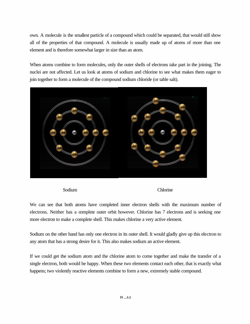
B -44
own. A molecule is the smallest particle of a compound which could be separated, that would still show all of the properties of that compound. A molecule is usually made up of atoms of more than one element and is therefore somewhat larger in size than an atom. When atoms combine to form molecules, only the outer shells of electrons take part in the joining. The nuclei are not affected. Let us look at atoms of sodium and chlorine to see what makes them eager to join together to form a molecule of the compound sodium chloride (or table salt). Sodium Chlorine We can see that both atoms have completed inner electron shells with the maximum number of electrons. Neither has a complete outer orbit however. Chlorine has 7 electrons and is seeking one more electron to make a complete shell. This makes chlorine a very active element. Sodium on the other hand has only one electron in its outer shell. It would gladly give up this electron to any atom that has a strong desire for it. This also makes sodium an active element. If we could get the sodium atom and the chlorine atom to come together and make the transfer of a single electron, both would be happy. When these two elements contact each other, that is exactly what happens; two violently reactive elements combine to form a new, extremely stable compound.
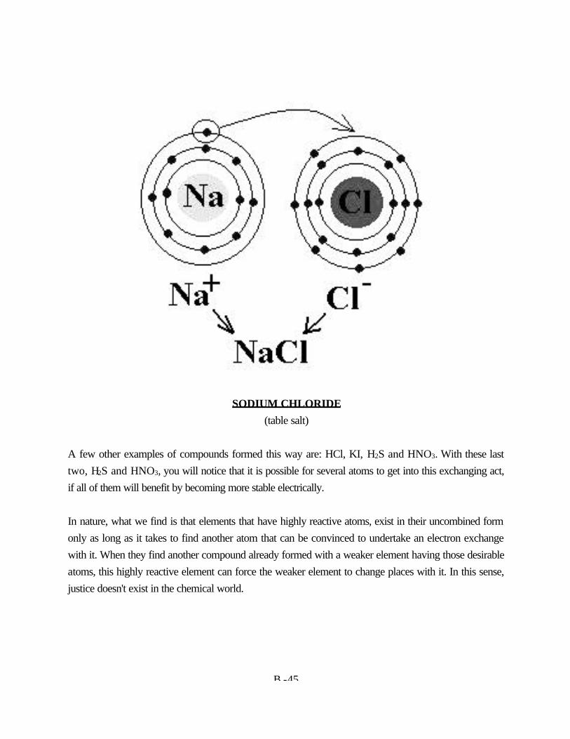
B -45
SODIUM CHLORIDE (table salt) A few other examples of compounds formed this way are: HCl, KI, H2S and HNO3. With these last two, H2S and HNO3, you will notice that it is possible for several atoms to get into this exchanging act, if all of them will benefit by becoming more stable electrically. In nature, what we find is that elements that have highly reactive atoms, exist in their uncombined form only as long as it takes to find another atom that can be convinced to undertake an electron exchange with it. When they find another compound already formed with a weaker element having those desirable atoms, this highly reactive element can force the weaker element to change places with it. In this sense, justice doesn't exist in the chemical world.
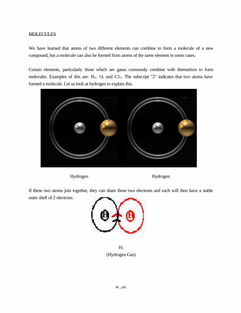
B -46
MOLECULES We have learned that atoms of two different elements can combine to form a molecule of a new compound, but a molecule can also be formed from atoms of the same element in some cases. Certain elements, particularly those which are gases commonly combine with themselves to form molecules. Examples of this are: H2, O2 and C12. The subscript "2" indicates that two atoms have formed a molecule. Let us look at hydrogen to explain this.
Hydrogen Hydrogen If these two atoms join together, they can share these two electrons and each will then have a stable outer shell of 2 electrons. H2 (Hydrogen Gas)
B -47
VALENCE The tendency of elements to form compounds through a shift of electronic structures is known as valence. Let us examine two methods of attaining a stable electronic distribution. A. Electrovalence As we said earlier, under some conditions, an atom can lose one or more electrons, which leaves the atom with a corresponding number of tiny positive electrical charges. Other atoms can gain one or more electrons in a similar manner which will give them negative charges. These positive and negative charges are equal and are attracted to each other by electrostatic action. Such atoms are said to be electrovalent and the term valence is used to describe the number of such bonds. Usually the ionized atoms of metals have positive charges (positive valence) and the symbols could be written as follows: Na+ , K+ , Ca++ , Al+++ (Cations) On the other hand, the atoms of nonmetals tend to become negatively charged or have negative valence. For example: Cl- , O-- , S--- (Anions) Electrovalent compounds are thus formed when anions and cations combine in the correct number to satisfy their valences. See Table B-3, Table of Electrovalence B. Covalence On the basis of electrovalence we would expect an element like carbon to be fairly inert and form few compounds; yet, this element forms more compounds than all the other elements put together. Obviously, there must be some other valence mechanism.
B -48
Carbon has four electrons in its outermost shell. Hydrogen has one electron in its only shell. If four hydrogen atoms were to approach a carbon atom so closely, that the shell of each hydrogen atom penetrated into the outermost shell of the carbon atom, the electrons in these interpenetrated shells would then be influenced by the nuclei of both types of atoms. Both atoms could then share these electrons. What we would have is a carbon atom sharing one electron with each of four hydrogen atoms. In effect, the hydrogen electron would be spending part of its time orbiting the hydrogen nucleus and part of its time orbiting the carbon nucleus.
Methane - Covalent Bonding In methane, each hydrogen atom now has two electrons, giving it the stable helium configuration in its orbits, and eight electrons are now associated with the carbon atom giving it the stable neon configuration. Both types of atoms have benefited by attaining a stable structure through this sharing process. Covalent compounds are thus formed by the sharing of pairs of electrons. When only one pair of electrons is shared by the same two atoms, the bond is said to be a single bond. When two pairs are shared, we describe this as a double bond and with three pairs, a triple bond.
B -49
ORGANIC COMPOUNDS Most compounds which follow the covalent method of bonding just described and contain the element carbon, are, or have been at some time, part of the earth’s life process. These are said to be organic compounds. Compounds which do not fit into this category are labeled inorganic. For example: Organic Compounds Inorganic Compounds CH4 HCl C2H2 Na2SO4 C6H5OH NH40H NaC2H3O4 AgNO3 RADICALS In many chemical compounds there are clusters of elements which behave as if they were a single element; such a group of elements is known as a radical.
B -50
Radicals exhibit some of the characteristics of ions, in that they all have an excess or a deficiency of electrons, causing the radical to posses an electrical charge. They will therefore combine with other ions or radicals to form compounds. Common examples of radicals are: NH4
+ ammonium NO2- nitrite
C2H3O2- acetate CO3
-- carbonate HCO3
- bicarbonate SO4-- sulphate
OH- hydroxide SO3-- sulphite
NO3- nitrate
Since ammonium is a positive radical, it will form compounds with all negative ions or radicals. For example: NH4Cl ammonium chloride (NH4)2CO3 ammonium carbonate Note that it takes two ammonium radicals to satisfy the electrical charge (valence) of the carbonate radical. If you look carefully at the names and formulas of the radicals you will notice that the suffixes -"ite" and "-ate" occur repeatedly. These suffixes are used only with radicals containing oxygen atoms. Notice that "-ite" radicals always contains fewer oxygen atoms that "-ate" radicals. For example: Sulphite SO3
-- Sulphate SO4--
Nitrite NO2- Nitrate NO3
- MOLECULAR WEIGHT When we were discussing atoms, we said that the relative mass of one atom compared to another is known as its atomic weight. We also said that the elements relative mass must be the average of its

B -39
mass, taking into account the abundance of natural isotopes found. Table B-3 is a list of International Relative Atomic Weights scaled to the relative atomic mass of carbon as 12.
International Relative Atomic Weights Actinium Ac 227 **
Aluminum Al 26.981538 Americium Am 243 Antimony Sb 121.760 Argon Ar 39.948 Arsenic As 74.92160 Astatine At 210 Barium Ba 137.327 Berkelium Bk 247 Beryllium Be 9.012182 Bismuth Bi 208.98038 Bohrium Bh 264 Boron B 10.811 Bromine Br 79.904 Cadmium Cd 112.411 Calcium Ca 40.078 Californium Cf 251 Carbon C 12.0107 Cerium Cc 140.116 Cesium CS 132.9054 Chlorine C l 35.453 Chromium Cr 51.9961 Cobalt Co 58.933200 Copper Cu 63.546 Curium Cm 247 Dubnium Db 262 Dyprosium Dy 162.50 Einsteinium Es 252 Erbium Er 167.259 Europium Eu 151.964 Fermium Fm 257 Fluorine F 18.9984032 Francium Fr 223 Gadolinium Gd 157.25 Gallium Ga 69.723 Germanium Ge 72.64 Gold An 196.96655 Hafnium Hf 178.49 Hassium Hs 277 Helium He 4.002602
Holmium Ho 164.93032 Hydrogen H 1.00794 Indium In 114.818 Iodine I 126.90447 Iridium Ir 192.217 Iron Fc 55.845 Krypton Kr 3.80 Lanthanum La 138.9055 Lawrencium Lr 262 Lead Pb 207.2 Lithium Li 6.941 Lutetium Lu 174.967 Magnesium M 24.3050 Manganese Mn 54.938049 Meitnerium Mt 268 Mendelevium Md 258 Mercury Hg 200.59 Molybdenum Mo 95.94 Neodymium Nd 144.24 Neon Ne 20.1797 Neptunium Np 237 Nickel Ni 58.6934 Niobium Nb 92.90638 Nitrogen N 14.0067 Nobelium No 259 Osmium Os 190.23 Oxygen Os 15.9994 Palladium Pd 106.42 Phosphorus P 30.973761 Platinum Pt 195.078 Plutonium Pu 244 Polonium Po 209 Potassium K 39.0983 Praseodymium Pr 140.90765 Promethium Pm 145 Protactinium Pa 231.03588 Radium Ra 226 Radon Rn 222
Rhenium Re 186.207 Rhodium Rh 102.90550 Rubidium Rb 85.4678 Ruthenium Ru 101.07 Rutherfordium Rf 267 Samarium Sm 150.36 Scandium Sc 44.955910 Selenium Se 78.96 Seaborgium Sg 266 Silicon Si 28.0855 Silver Ag 107.8682 Sodium Na 22.989770 Strontium Sr 87.62 Sulfur S 32.065 Tantalum Ta 180.9479 Technetium Tc 98 Tellurium Te 127.60 Terbium Tb 158.92534 Thallium TI 204.3833 Thorium Th 232.0381 Thulium Tm 168.93421 Tin Sn 118.710 Titanium Ti 47.867 Tungsten W 183.84 Ununilium Uun 281 Ununquadium Uuq 289 Uranium U 238.02891 Vanadium V 50.9415 Xenon Xe 131.293 Ytterbium Yh 173.04 Yttrium Y 88.90585 Zinc Zn 65.39 Zirconium Zr 91.22
B -38
To find the relative mass of any molecule or its molecular weight, one simply adds up the atomic weights of each of the atoms in the molecule. For example: 1. HOCl (Hypochlorous Acid) Molecular weight = H + O + Cl = 1.008 + 15.999 + 35.453 = 52.460 2. FeSO4 (Ferrous Sulphate) Molecular weight = Fe + S + 4 (O) = 55.847 + 32.064 + 4 (15.999) = 151.907 3. Ca(OH)2 (Hydrated Lime) Molecular weight = Ca + 2 (O + H) = 40.08 + 2 (15.999 + 1.008) = 74.094 Since these weights are only relative masses, they have no units. However, the proportions of each atom which combine to form a molecule are always the same. For example, HCl, hydrochloric acid will always contain 1.008 parts by weight of hydrogen and 35.453 parts by weight of chlorine. If the parts or units we choose are grams, HCl will always contain 1.008 grams hydrogen and 35.453 grams of chlorine in every 36.461 grams of HCl. In this way we can express the relative masses of atoms as gram atomic weights and their combined weights as gram molecular weights. These terms will become especially important to us later when we discuss the preparation of standard solutions. NAMING COMPOUNDS Binary Compounds

B -39
Binary compounds are those which are made up of two elements; simple examples are the salts NaCl and KCl. The names of these compounds consist of the names of the two elements, the positive element first, with the ending of the second element changed to "ide". eg: NaCl - sodium chloride KCl - potassium chloride If the metal has two different oxidation numbers (valences) this is indicated by the use of the suffix "-ous" for the lower or weaker example and "-ic" for the highest or stronger one. eg: FeCl2 - ferrous chloride FeCl3 - ferric chloride Occasionally two elements can form into two or more compounds of different proportion and a different naming system is resorted to. The name of the second element is preceded by a prefix -eg- mono-(one), di-(two), tri-(three), tetra(four) etc. Oxides are good examples of this. eg: CO - carbon monoxide CO2 - carbon dioxide P2O3 - phosphorous trioxide P2O5 - phosphorous pentoxide Compounds Containing Radicals Naming compounds containing radicals is done in the same way as for binary compounds, except that the name for the radical is used rather than the names of its component elements eg: CaCO3 - calcium carbonate Na2SO4 - sodium sulfate NH4Cl - ammonium chloride
B -40
KOH - potassium hydroxide Fe(OH)2 - ferrous hydroxide Fe(OH)3 - ferric hydroxide Acids Binary acids are named using the prefix "hydro-" in front of the name of the negative element, followed by the suffix "-ic". eg: HF - hydrofluoric acid HCl - hydrochloric acid HBr - hydrobromic acid HI - hydroiodic acid Many common acid molecules contain hydrogen, a nonmetal (negative element), and oxygen. Since the amount of oxygen often varies, the name of the most common form of the acid in the series consists of the stem of the name of the nonmetal with the suffix "-ic". The acid containing one less atom of oxygen than the common form has the suffix "-ous". The acid containing one more atom of oxygen than the common form has the prefix "per-" and the suffix "-ic". The acid containing two less atoms of oxygen than the common form has the prefix "hypo-" and the suffix "-ous". eg: HNO3 - nitric acid HNO2 - nitrous acid HCl03 - chloric acid HClO2 - chlorous acid HClO - hypochlorous acid H2SO4 - sulfuric acid H2SO3 - sulfurous acid H3PO4 - phosphoric acid H3PO3 - phosphorous acid H2CO3 - carbonic acid H2C2O4 - oxalic acid H3BO3 - boric acid
B -41
SUBJECT: SOLUTION PREPARATION OBJECTIVES: The student will be able to: 1. Select the correct definition from a given list for each of the following items: a. solute b. solvent c. normality d. molarity e. percentage composition 2. Calculate the weight in grams of a given compound required to make a litre of 3 normal solution. 3. List the quantities represented in an indicated list of S.I. prefixes, by a given quantity in grams
B -42
SOLUTIONS A solution consists of two components, a solvent which is the dissolving medium and a solute which is the substance dissolved. The solute is dispersed as molecules or ions and the distribution of the solute is perfectly homogenous throughout the solution. Common examples of solvent and solute are: SOLVENT SOLUTE water sugar alcohol table salt chloroform baking soda vinegar starch A concentrated solution is one which contains a relatively large amount of solute per unit volume of solution. A dilute solution is one which contains a relatively small amount of solute per unit volume of solution. The words "strong" and "weak" should not be used when referring to the concentration of a solution. Strong and weak are terms that are more properly used to describe the chemical activity of a substance. CONCENTRATION The concentration of a solution can be expressed in a number of ways. The units of expression give an indication of the way in which a solution of this concentration would be made up. The most common units of expression for concentration are: 1. Molarity 2. Normality 3. Molality 4. Percentage Composition MOLARITY
B -43
The molarity of a solution is the number of gram molecular weights of solute per litre of solution. "Gram molecular weight" is sometimes abbreviated as mole, so molarity becomes Molarity (M) = Number of moles of solute Litre of solution A solution which contains a half mole of solute per litre of solution would therefore be a 0.5 M solution. NORMALITY The normality of a solution is the number of gram equivalent weights of solute per litre of solution. "Gram equivalent weight" is a new term and is often abbreviated as equivalent. Normality (N) = Number of equivalents of solute Litre of solution The equivalent weight of a compound is found from the net positive valance of the compound. If we take the valance of the positive (+) part of the compound and multiply it by its subscript we will have the total number of positive charges available, or net positive valence. net positive valence = (valence of + element) x (its subscript if any) The equivalent weight of any compound is then found from the relationship equivalent weight = molecular weight net positive valence Let us use solutions of NaCl and K2CO3 in water to illustrate this principle. To make up a 1 N solution of either salt we will need 1 gram equivalent weight (equivalent) of each dissolved in 1 litre of solution. For NaCl, the net positive valence is 1 so the equivalent weight of NaCl is the same as its molecular weight.
B -44
For K2CO3 however, the net positive valence is 2 so the equivalent weight of K2C03 is its molecular weight over 2. MOLALITY The molality of a solution is the number of moles of solute per 1000 grams of solvent. Since the solvent will not always be water, this method of expression is considerably different from molarity. molality (m) = Number of moles of solute 1000 grams of solvent PERCENTAGE COMPOSITION This method of expression of concentration may use either percentage by weight or percentage by volume as its units. % by weight = weight of solute x 100 weight of solution % by volume = volume of solute x 100 volume of solution Percentage by weight is usually used in referring to solids dissolved in liquids. Percentage by volume is normally used with reference to gases in gases, or liquids in liquids. CONCENTRATION EXAMPLE If we were given the task of preparing a 3 N solution of K2CO3, we must start with the fact that 3N = 3 equivalents of solute Litre of solution What we now need to know is the gram equivalent weight of K2CO3. Let's start out by finding the gram molecular weight of K2CO3:
B -45
gm molecular wt K2CO3 = 2 (39.102) + 12.011 + 3 (15.999) = 138.212 gm Since the valence of K is 1, the net positive valence of K2CO3 is 2. gm equivalent wt of K2CO3 = gm molecular wt net positive valence = 138.212 gm 2 = 69.106 gm Since, as we said earlier, 3N = 3 equivalents of solute Litre of solution we can now substitute 3N = 3 (69.106 gm) Litre of solution = 207.218 gm K2CO3 Litre of solution We can now make up this solution by weighing accurately 207.218 gm of dried K2CO3, placing this amount in a l-litre volumetric flask and diluting the solution to occupy exactly 1 litre. SOLUTION PREPARATION Where solutions of known concentration are used as standards in the analysis of other compounds, the preparation of these solutions must be undertaken with great care.
B -46
Atomic weights are given in the tables with great precision, and gram molecular or gram equivalent weights can be calculated to at least 4 decimal places. It is our responsibility then to see that only devices and procedures capable of continuing this precision are used in the preparation of standard solutions. To prepare a standard solution, approximate desired quantities of granular or powdered solute are deposited in a weighing bottle, paper weigh-boat or aluminum weighing dish and dried for at least one hour in a laboratory oven at 103oC. After drying, the weighing bottle containing the sample is placed in a laboratory desiccator to cool to room temperature in a dry atmosphere. The net weight of the solute is then determined using an analytical balance capable of 0.1 mg precision (0.0001 g). If any minor changes in the finished weight are desired, small amounts of solute may be removed at this time and the sample redried and cooled. The sample is considered to have reached stable weight when three consecutive desiccating and weighing cycles results in a difference of less than 1 mg. The mean of the three weight values is then taken as the weight of the sample. When the desired final weight is reached, the solute is transferred, using a powder funnel, from the weighing container to a 1 litre volumetric flask. A "rubber policeman" may be used to push the last few grains of powder into the funnel. A stream of distilled water from a wash bottle is then used to flush the weighing container and the powder funnel to dislodge and dissolve any stubborn powder. The powder in the volumetric flask is dissolved in a small amount of distilled water by inverting or swirling the flask. When all of the powder is dissolved, enough distilled water is added to bring the level in the flask almost to the engraved line on the neck. The contents of the flask are then mixed by inverting several times. When the solution is considered to be well mixed, it is allowed to stand for sometime so that all of the solution will drain back into the bottom of the flask. Then, using a fine-tipped wash bottle, distilled water is added slowly to bring the bottom of the meniscus curve exactly level with the engraved line.
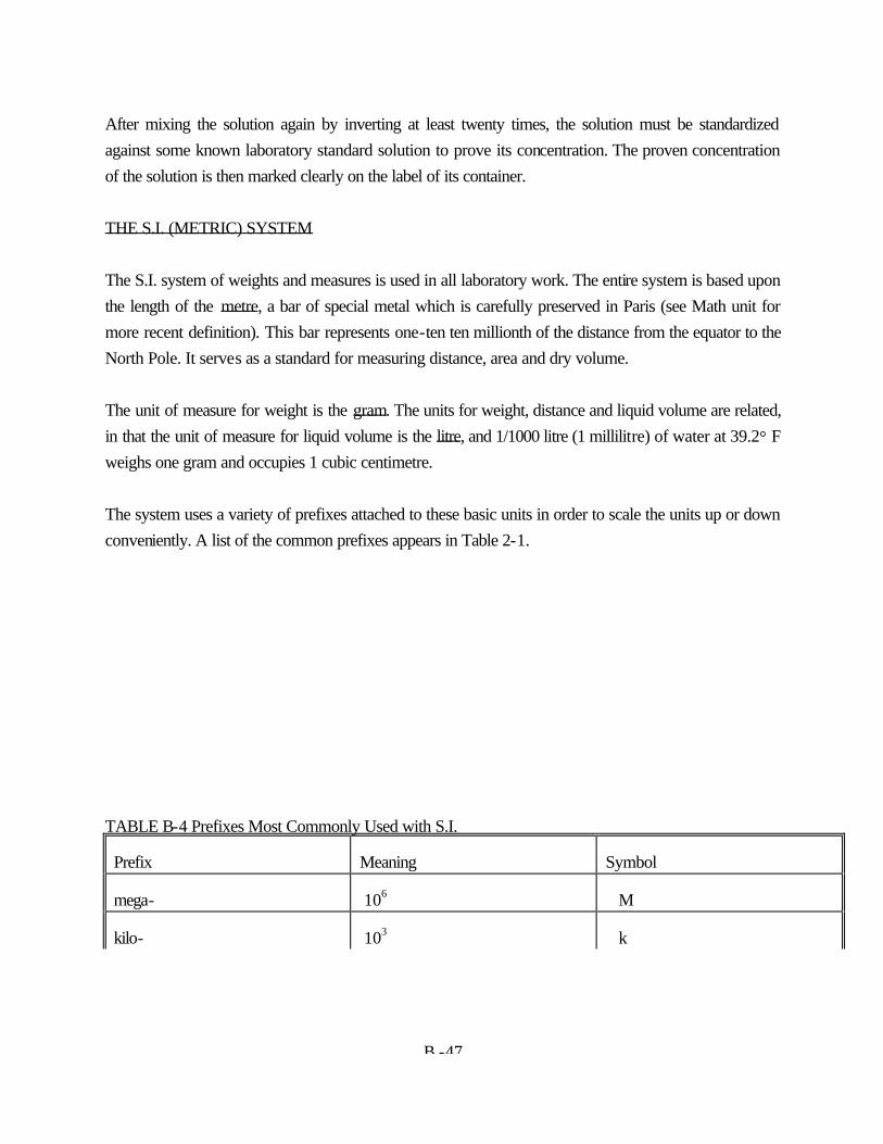
B -47
After mixing the solution again by inverting at least twenty times, the solution must be standardized against some known laboratory standard solution to prove its concentration. The proven concentration of the solution is then marked clearly on the label of its container. THE S.I. (METRIC) SYSTEM The S.I. system of weights and measures is used in all laboratory work. The entire system is based upon the length of the metre, a bar of special metal which is carefully preserved in Paris (see Math unit for more recent definition). This bar represents one-ten ten millionth of the distance from the equator to the North Pole. It serves as a standard for measuring distance, area and dry volume. The unit of measure for weight is the gram. The units for weight, distance and liquid volume are related, in that the unit of measure for liquid volume is the litre, and 1/1000 litre (1 millilitre) of water at 39.2° F weighs one gram and occupies 1 cubic centimetre. The system uses a variety of prefixes attached to these basic units in order to scale the units up or down conveniently. A list of the common prefixes appears in Table 2-1. TABLE B-4 Prefixes Most Commonly Used with S.I.
Prefix Meaning Symbol
mega- 106 M
kilo- 103 k
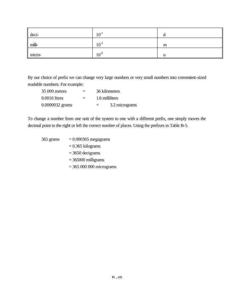
B -48
deci- 10-1 d
milli- 10-3 m
micro- 10-6 u
By our choice of prefix we can change very large numbers or very small numbers into convenient-sized readable numbers. For example: 35 000 metres = 36 kilometres 0.0016 litres = 1.6 millilitres 0.0000032 grams = 3.2 micrograms To change a number from one unit of the system to one with a different prefix, one simply moves the decimal point to the right or left the correct number of places. Using the prefixes in Table B-5. 365 grams = 0.000365 megagrams = 0.365 kilograms = 3650 decigrams = 365000 milligrams = 365 000 000 micrograms
ADDENDUM C
GUIDELINES FOR CANADIAN DRINKING WATER QUALITY

Summary of Guidelines for CanadianDrinking Water Quality
Prepared by theFederal–Provincial–Territorial Committee on Drinking Water
of theFederal–Provincial–Territorial Committee
on Environmental and Occupational Health
April 2002
The Guidelines for Canadian Drinking Water Quality are published by Health Canada. In order to keepinterested parties informed of changes to the Guidelines between publication of new editions, this summary table isupdated and published every spring on Health Canada’s website (www.hc-sc.gc.ca/waterquality). The April 2002“Summary of Guidelines for Canadian Drinking Water Quality” supercedes all previous versions, including thatcontained in the published booklet.
Membership of the Federal–Provincial–Territorial Committee on Drinking Waterand Secretariat
Provincial and Territorial RepresentativesAlberta Department of Environment Mr. Karu ChinniahBritish Columbia Ministry of Health Planning Mr. Barry BoettgerManitoba Department of Conservation Mr. Don RocanNew Brunswick Department of Health and Wellness Mr. Ivan BrophyNewfoundland and Labrador Department of Environment Mr. Martin GoebelNorthwest Territories Department of Health and Social Services Mr. Duane FlemingNova Scotia Department of Environment and Labour Mr. David BrigginsNunavut Territory Department of Health and Social Services Mr. Bruce TrotterOntario Ministry of Environment and Energy Mr. Adam SochaPrince Edward Island Department of Fisheries, Aquaculture and Environment Mr. George SomersQuébec Ministère de l’Environnement Ms. Hélène TremblaySaskatchewan Department of the Environment Mr. Thon PhommavongYukon Territory Department of Health and Social Services Ms. Patricia Brooks
Federal RepresentativesHealth Canada Ms. Michèle GiddingsEnvironment Canada Ms. Connie Gaudet
Liaison OfficersDr. Jim Popplow Federal–Provincial–Territorial Committee on Environmental and Occupational HealthMr. Tim Macaulay Canadian Advisory Council on Plumbing
Committee SecretaryHealth Canada (Water Quality and Health Bureau, Safe Environments Programme,
Healthy Environments and Consumer Safety Branch) Mr. David Green
1
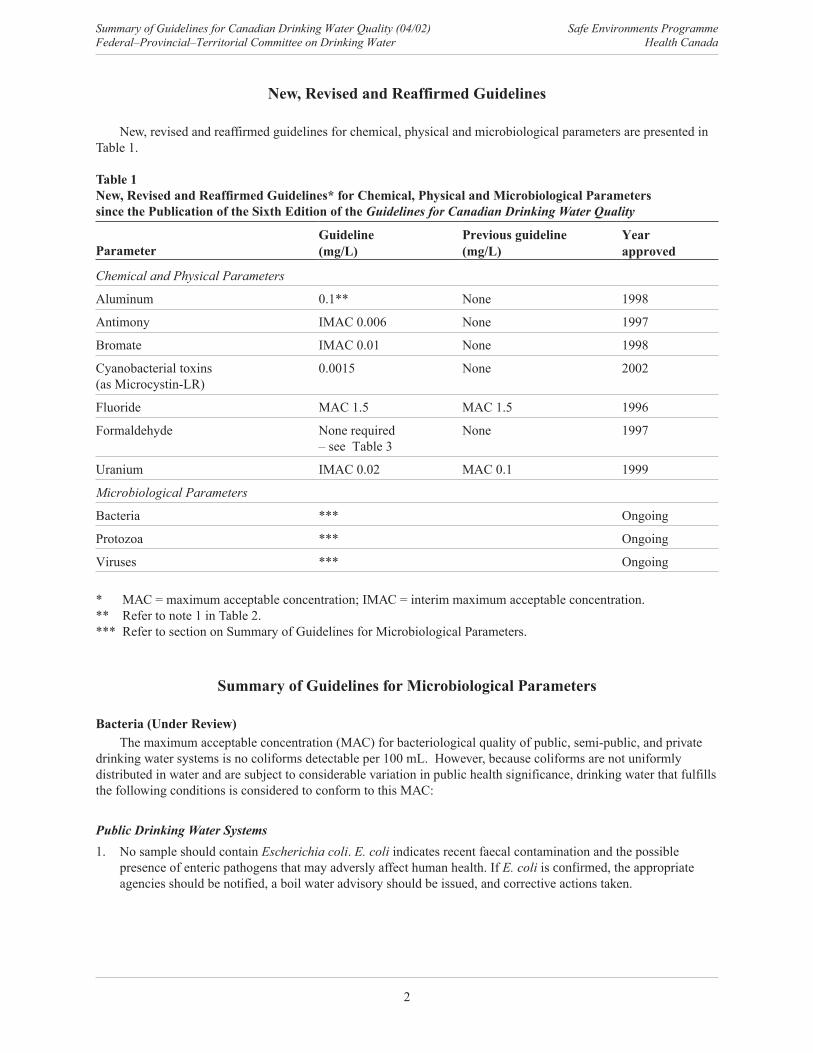
New, Revised and Reaffirmed Guidelines
New, revised and reaffirmed guidelines for chemical, physical and microbiological parameters are presented inTable 1.
Table 1New, Revised and Reaffirmed Guidelines* for Chemical, Physical and Microbiological Parameterssince the Publication of the Sixth Edition of the Guidelines for Canadian Drinking Water Quality
ParameterGuideline(mg/L)
Previous guideline(mg/L)
Yearapproved
Chemical and Physical Parameters
Aluminum 0.1** None 1998
Antimony IMAC 0.006 None 1997
Bromate IMAC 0.01 None 1998
Cyanobacterial toxins(as Microcystin-LR)
0.0015 None 2002
Fluoride MAC 1.5 MAC 1.5 1996
Formaldehyde None required– see Table 3
None 1997
Uranium IMAC 0.02 MAC 0.1 1999
Microbiological Parameters
Bacteria *** Ongoing
Protozoa *** Ongoing
Viruses *** Ongoing
* MAC = maximum acceptable concentration; IMAC = interim maximum acceptable concentration.** Refer to note 1 in Table 2.*** Refer to section on Summary of Guidelines for Microbiological Parameters.
Summary of Guidelines for Microbiological Parameters
Bacteria (Under Review)The maximum acceptable concentration (MAC) for bacteriological quality of public, semi-public, and private
drinking water systems is no coliforms detectable per 100 mL. However, because coliforms are not uniformlydistributed in water and are subject to considerable variation in public health significance, drinking water that fulfillsthe following conditions is considered to conform to this MAC:
Public Drinking Water Systems1. No sample should contain Escherichia coli. E. coli indicates recent faecal contamination and the possible
presence of enteric pathogens that may adversly affect human health. If E. coli is confirmed, the appropriateagencies should be notified, a boil water advisory should be issued, and corrective actions taken.
Summary of Guidelines for Canadian Drinking Water Quality (04/02) Safe Environments ProgrammeFederal–Provincial–Territorial Committee on Drinking Water Health Canada
2
2. No consecutive samples from the same site or not more than 10% of samples from the distribution system in agiven calendar month should show the presence of total coliform bacteria. The ability of total coliforms toindicate the presence of faecal pollution is less reliable than E. coli. However, this group of bacteria is a goodindicator of quality control. The presence of total coliforms does not necessarily require the issuance of a boilwater advisory but corrective actions should be taken.
Semi-public and Private Drinking Water Supply Systems1. No sample should contain E. coli. As stated above, the presence of E. coli indicates faecal contamination and
the possible presence of enteric pathogens; therefore the water is unsafe to drink. If E. coli is detected, a boilwater advisory should be issued and corrective actions taken.
2. No sample should contain total coliform bacteria. In non-disinfected well water, the presence of total coliformbacteria in the absence of E. coli indicates the well is prone to surface water infiltration and therefore at risk offaecal contamination. In disinfected water systems, the presence of total coliform bacteria indicates a failure inthe disinfection process. In both disinfected and non-disinfected systems, total coliform detection may alsoindicate the presence of biofilm in the well or plumbing system. The degree of response to the presence of totalcoliform bacteria, in the absence of E. coli, may be site specific and can vary between jurisdictions.
Protozoa (Under Review)Numerical guidelines for the protozoa Giardia and Cryptosporidium are not proposed at this time. Routine
methods available for the detection of protozoan cysts and oocysts suffer from low recovery rates and do not provideany information on their viability or human infectivity. Nevertheless, until better monitoring data and information onthe viability and infectivity of cysts and oocysts present in drinking water are available, measures to reduce the riskof illness as much as possible should be implemented. If viable, human-infectious cysts or oocysts are present orsuspected to be present in source waters or if Giardia or Cryptosporidium has been responsible for past waterborneoutbreaks in a community, a treatment regime and a watershed or wellhead protection plan (where feasible) or othermeasures known to reduce the risk of illness should be implemented.
Viruses (Under Review)Numerical guidelines for human enteric viruses are not proposed at this time. There are more than 120 types of
human enteric viruses, many of which are non-culturable. Testing is complicated, expensive, not available for allviruses, and beyond the capabilities of most laboratories involved in routine water quality monitoring. The bestmeans of safeguarding against the presence of human enteric viruses are based upon the application of adequatetreatment and the absence of faecal indicator organisms, such as Escherichia coli.
Boil Water AdvisoriesGeneral guidance on the issuing and rescinding of boil water advisories is provided. In the event of an advisory,
a rolling boil for 1 minute is considered adequate.
Summary of Guidelines for Chemical and Physical Parameters
Parameters with GuidelinesGuidelines for all chemical and physical parameters, including all new, revised and reaffirmed maximum
acceptable concentrations (MACs), interim maximum acceptable concentrations (IMACs) and aesthetic objectives(AOs), are listed in Table 2. For more information on the drinking water guideline for any particular compound,please refer to the Supporting Documentation for the parameter of concern.
Safe Environments Programme Summary of Guidelines for Canadian Drinking Water Quality (04/02)Health Canada Federal–Provincial–Territorial Committee on Drinking Water
3
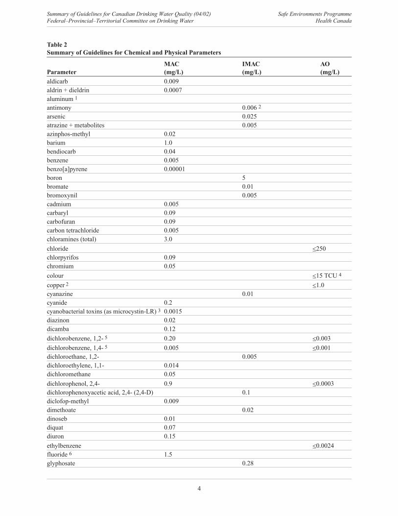
Table 2Summary of Guidelines for Chemical and Physical Parameters
MAC IMAC AOParameter (mg/L) (mg/L) (mg/L)aldicarb 0.009aldrin + dieldrin 0.0007aluminum 1
antimony 0.006 2
arsenic 0.025atrazine + metabolites 0.005azinphos-methyl 0.02barium 1.0bendiocarb 0.04benzene 0.005benzo[a]pyrene 0.00001boron 5bromate 0.01bromoxynil 0.005cadmium 0.005carbaryl 0.09carbofuran 0.09carbon tetrachloride 0.005chloramines (total) 3.0chloride �250chlorpyrifos 0.09chromium 0.05colour �15 TCU 4
copper 2 �1.0cyanazine 0.01cyanide 0.2cyanobacterial toxins (as microcystin-LR) 3 0.0015diazinon 0.02dicamba 0.12dichlorobenzene, 1,2- 5 0.20 �0.003dichlorobenzene, 1,4- 5 0.005 �0.001dichloroethane, 1,2- 0.005dichloroethylene, 1,1- 0.014dichloromethane 0.05dichlorophenol, 2,4- 0.9 �0.0003dichlorophenoxyacetic acid, 2,4- (2,4-D) 0.1diclofop-methyl 0.009dimethoate 0.02dinoseb 0.01diquat 0.07diuron 0.15ethylbenzene �0.0024fluoride 6 1.5glyphosate 0.28
Summary of Guidelines for Canadian Drinking Water Quality (04/02) Safe Environments ProgrammeFederal–Provincial–Territorial Committee on Drinking Water Health Canada
4
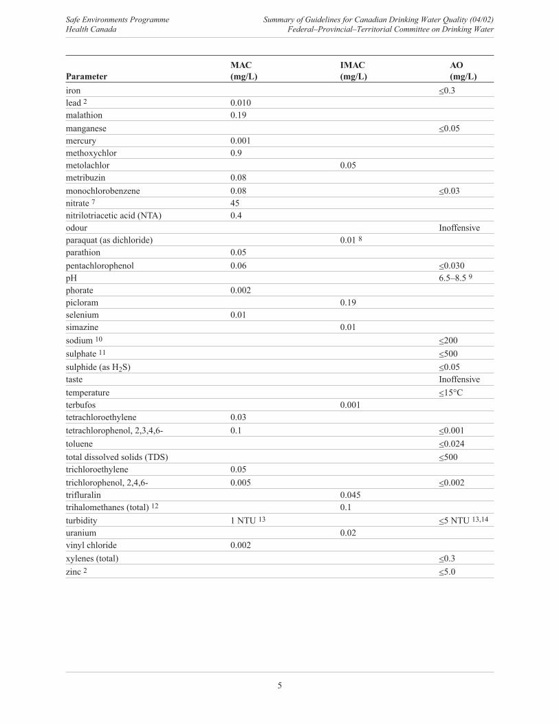
MAC IMAC AOParameter (mg/L) (mg/L) (mg/L)iron �0.3lead 2 0.010malathion 0.19manganese �0.05mercury 0.001methoxychlor 0.9metolachlor 0.05metribuzin 0.08monochlorobenzene 0.08 �0.03nitrate 7 45nitrilotriacetic acid (NTA) 0.4odour Inoffensiveparaquat (as dichloride) 0.01 8
parathion 0.05pentachlorophenol 0.06 �0.030pH 6.5–8.5 9
phorate 0.002picloram 0.19selenium 0.01simazine 0.01sodium 10 �200sulphate 11 �500sulphide (as H2S) �0.05taste Inoffensivetemperature �15�Cterbufos 0.001tetrachloroethylene 0.03tetrachlorophenol, 2,3,4,6- 0.1 �0.001toluene �0.024total dissolved solids (TDS) �500trichloroethylene 0.05trichlorophenol, 2,4,6- 0.005 �0.002trifluralin 0.045trihalomethanes (total) 12 0.1turbidity 1 NTU 13 �5 NTU 13,14
uranium 0.02vinyl chloride 0.002xylenes (total) �0.3zinc 2 �5.0
Safe Environments Programme Summary of Guidelines for Canadian Drinking Water Quality (04/02)Health Canada Federal–Provincial–Territorial Committee on Drinking Water
5
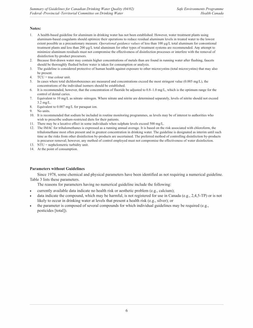
Notes:1. A health-based guideline for aluminum in drinking water has not been established. However, water treatment plants using
aluminum-based coagulants should optimize their operations to reduce residual aluminum levels in treated water to the lowestextent possible as a precautionary measure. Operational guidance values of less than 100 µg/L total aluminum for conventionaltreatment plants and less than 200 µg/L total aluminum for other types of treatment systems are recommended. Any attempt tominimize aluminum residuals must not compromise the effectiveness of disinfection processes or interfere with the removal ofdisinfection by-product precursors.
2. Because first-drawn water may contain higher concentrations of metals than are found in running water after flushing, faucetsshould be thoroughly flushed before water is taken for consumption or analysis.
3. The guideline is considered protective of human health against exposure to other microcystins (total microcystins) that may alsobe present.
4. TCU = true colour unit.5. In cases where total dichlorobenzenes are measured and concentrations exceed the most stringent value (0.005 mg/L), the
concentrations of the individual isomers should be established.6. It is recommended, however, that the concentration of fluoride be adjusted to 0.8–1.0 mg/L, which is the optimum range for the
control of dental caries.7. Equivalent to 10 mg/L as nitrate–nitrogen. Where nitrate and nitrite are determined separately, levels of nitrite should not exceed
3.2 mg/L.8. Equivalent to 0.007 mg/L for paraquat ion.9. No units.10. It is recommended that sodium be included in routine monitoring programmes, as levels may be of interest to authorities who
wish to prescribe sodium-restricted diets for their patients.11. There may be a laxative effect in some individuals when sulphate levels exceed 500 mg/L.12. The IMAC for trihalomethanes is expressed as a running annual average. It is based on the risk associated with chloroform, the
trihalomethane most often present and in greatest concentration in drinking water. The guideline is designated as interim until suchtime as the risks from other disinfection by-products are ascertained. The preferred method of controlling disinfection by-productsis precursor removal; however, any method of control employed must not compromise the effectiveness of water disinfection.
13. NTU = nephelometric turbidity unit.14. At the point of consumption.
Parameters without GuidelinesSince 1978, some chemical and physical parameters have been identified as not requiring a numerical guideline.
Table 3 lists these parameters.The reasons for parameters having no numerical guideline include the following:
� currently available data indicate no health risk or aesthetic problem (e.g., calcium);� data indicate the compound, which may be harmful, is not registered for use in Canada (e.g., 2,4,5-TP) or is not
likely to occur in drinking water at levels that present a health risk (e.g., silver); or� the parameter is composed of several compounds for which individual guidelines may be required (e.g.,
pesticides [total]).
Summary of Guidelines for Canadian Drinking Water Quality (04/02) Safe Environments ProgrammeFederal–Provincial–Territorial Committee on Drinking Water Health Canada
6
Table 3Summary List of Parameters without Guidelines
Parameter Parameterammonia pesticides (total)asbestos phenolscalcium phthalic acid esters (PAE)chlordane (total isomers) polycyclic aromatic hydrocarbons (PAH) 2
dichlorodiphenyltrichloroethane (DDT) + metabolites radonendrin resin acidsformaldehyde silvergasoline tanninhardness 1 temephosheptachlor + heptachlor epoxide total organic carbonlignin toxaphenelindane triallatemagnesium trichlorophenoxyacetic acid, 2,4,5- (2,4,5-T)methyl-parathion trichlorophenoxypropionic acid, 2,4,5- (2,4,5-TP)mirex
Notes:1. Public acceptance of hardness varies considerably. Generally, hardness levels between 80 and 100 mg/L (as CaCO3) are considered
acceptable; levels greater than 200 mg/L are considered poor but can be tolerated; those in excess of 500 mg/L are normallyconsidered unacceptable. Where water is softened by sodium ion exchange, it is recommended that a separate, unsoftened supplybe retained for culinary and drinking purposes.
2. Other than benzo[a]pyrene.
Summary of Guidelines for Radiological Parameters
In setting dose guidelines for radionuclides in drinking water, it is recognized that water consumptioncontributes only a portion of the total radiation dose and that some radionuclides present are natural in origin andtherefore cannot be excluded. Consequently, maximum acceptable concentrations (MACs) for radionuclides indrinking water have been derived based on a committed effective dose of 0.1 mSv* from one year’s consumption ofdrinking water. This dose represents less than 5% of the average annual dose attributable to natural backgroundradiation.
To facilitate the monitoring of radionuclides in drinking water, the reference level of dose is expressed as anactivity concentration, which can be derived for each radionuclide from published radiological data. The NationalRadiological Protection Board has calculated dose conversion factors (DCFs) for radionuclides based on metabolicand dosimetric models for adults and children. Each DCF provides an estimate of the 50-year committed effectivedose resulting from a single intake of 1 Bq** of a given radionuclide.
The MACs of radionuclides in public water supplies are derived from adult DCFs, assuming a daily water intakeof 2 L, or 730 L/year, and a maximum committed effective dose of 0.1 mSv, or 10% of the InternationalCommission on Radiological Protection limit on public exposure:
MAC (Bq/L) = 1 � 10-4 (Sv/year)
730 (L/year) � DCF (Sv/Bq)
* Sievert (Sv) is the unit of radiation dose. It replaces the old unit, rem (1 rem = 0.01 Sv).** Becquerel (Bq) is the unit of activity of a radioactive substance, or the rate at which transformations occur in the substance.
One becquerel is equal to one transformation per second and is approximately equal to 27 picocuries (pCi).
Safe Environments Programme Summary of Guidelines for Canadian Drinking Water Quality (04/02)Health Canada Federal–Provincial–Territorial Committee on Drinking Water
7
When two or more radionuclides are found in drinking water, the following relationship should be satisfied:
C1 +c2 + ...
ci��
MAC1 MAC2 MACi
where ci and MACi are the observed and maximum acceptable concentrations, respectively, for each contributingradionuclide.
MACs for radionuclides that should be monitored in water samples are listed in Table 4. If a sample is analysedby gamma-spectroscopy, additional screening for radionuclides that may be present under certain conditions can beperformed. MACs for these radionuclides are given in Table 5. MACs for a number of additional radionuclides, bothnatural and artificial, can be found in the sixth edition of the guidelines booklet.
Water samples may be initially screened for radioactivity using techniques for gross alpha and gross betaactivity determinations. Compliance with the guidelines may be inferred if the measurements for gross alpha andgross beta activity are less than 0.1 Bq/L and 1 Bq/L, respectively, as these are lower than the strictest MACs.Sampling and analyses should be carried out often enough to accurately characterize the annual exposure. If thesource of the activity is known, or expected, to be changing rapidly with time, then the sampling frequency shouldreflect this factor. If there is no reason to suppose that the source varies with time, then the sampling may be doneannually. If measured concentrations are consistent and well below the reference levels, this would be an argumentfor reducing the sampling frequency. On the other hand, the sampling frequency should be maintained, or evenincreased, if concentrations are approaching the reference levels. In such a case, the specific radionuclides should beidentified and individual activity concentrations measured.
Table 4Primary List of Radionuclides – Maximum Acceptable ConcentrationsRadionuclide Half-life t½ DCF (Sv/Bq) MAC (Bq/L)
Natural RadionuclidesLead-210 210Pb 22.3 years 1.3 × 10⁻⁶ 0.1Radium-224 224Ra 3.66 days 8.0 × 10⁻⁸ 2Radium-226 226Ra 1600 years 2.2 × 10⁻⁷ 0.6Radium-228 228Ra 5.76 years 2.7 × 10⁻⁷ 0.5Thorium-228 228Th 1.91 years 6.7 × 10⁻⁸ 2Thorium-230 230Th 7.54 × 10⁴ years 3.5 × 10⁻⁷ 0.4Thorium-232 232Th 1.40 × 10¹⁰ years 1.8 × 10⁻⁶ 0.1Thorium-234 234Th 24.1 days 5.7 × 10⁻⁹ 20Uranium-234 234U 2.45 × 10⁵ years 3.9 × 10⁻⁸ 4*Uranium-235 235U 7.04 × 10⁸ years 3.8 × 10⁻⁸ 4*Uranium-238 238U 4.47 × 10⁹ years 3.6 × 10⁻⁸ 4*
Artificial RadionuclidesCesium-134 134Cs 2.07 years 1.9 × 10⁻⁸ 7Cesium-137 137Cs 30.2 years 1.3 × 10⁻⁸ 10Iodine-125 125I 59.9 days 1.5 × 10⁻⁸ 10Iodine-131 131I 8.04 days 2.2 × 10⁻⁸ 6Molybdenum-99 99Mo 65.9 hours 1.9 × 10⁻⁹ 70Strontium-90 90Sr 29 years 2.8 × 10⁻⁸ 5Tritium** 3H 12.3 years 1.8 × 10⁻¹¹ 7000
* The activity concentration of natural uranium corresponding to the chemical guideline of 0.02 mg/L is about 0.5 Bq/L.** Tritium is also produced naturally in the atmosphere in significant quantities.
Summary of Guidelines for Canadian Drinking Water Quality (04/02) Safe Environments ProgrammeFederal–Provincial–Territorial Committee on Drinking Water Health Canada
8
Table 5Secondary List of Radionuclides – Maximum Acceptable Concentrations (MACs)Radionuclide Half-life t½ DCF (Sv/Bq) MAC (Bq/L)
Natural RadionuclidesBeryllium-7 7Be 53.3 days 3.3 × 10⁻¹¹ 4000Bismurh-210 210Bi 5.01 days 2.1 × 10⁻⁹ 70Polonium-210 210Po 138.4 days 6.2 × 10⁻⁷ 0.2
Artificial Radionuclides**Americium-241 241Am 432 years 5.7 × 10⁻⁷ 0.2Antimony-122 122Sb 2.71 days 2.8 × 10⁻⁹ 50Antimony-124 124Sb 60.2 days 3.6 × 10⁻⁹ 40Antimony-125 125Sb 2.76 years 9.8 × 10⁻¹⁰ 100Barium-140 140Ba 12.8 days 3.7 × 10⁻⁹ 40Bromine-82 82Br 35.3 hours 4.8 × 10⁻¹⁰ 300Calcium-45 45Ca 165 days 8.9 × 10⁻¹⁰ 200Calcium-47 47Ca 4.54 days 2.2 × 10⁻⁹ 60Carbon-14 14C 5730 years 5.6 × 10⁻¹⁰ 200Cerium-141 141Ce 32.5 days 1.2 × 10⁻⁹ 100Cerium-144 144Ce 284.4 days 8.8 × 10⁻⁹ 20Cesium-131 131Cs 9.69 days 6.6 × 10⁻¹¹ 2000Cesium-136 136Cs 13.1 days 3.0 × 10⁻⁹ 50Chromium-51 51Cr 27.7 days 5.3 × 10⁻¹¹ 3000Cobalt-57 57Co 271.8 days 3.5 × 10⁻⁹ 40Cobalt-58 58Co 70.9 days 6.8 × 10⁻⁹ 20Cobalt-60 60Co 5.27 years 9.2 × 10⁻⁸ 2Gallium-67 67Ga 78.3 hours 2.6 × 10⁻¹⁰ 500Gold-198 198Au 2.69 days 1.6 × 10⁻⁹ 90Indium-111 111In 2.81 days 3.9 × 10⁻¹⁰ 400Iodine-129 129I 1.60 × 10⁷ years 1.1 × 10⁻⁷ 1Iron-55 55Fe 2.68 years 4.0 × 10⁻¹⁰ 300Iron-59 59Fe 44.5 days 3.1 × 10⁻⁹ 40Manganese-54 54Mn 312.2 days 7.3 × 10⁻¹⁰ 200Mercury-197 197Hg 64.1 hours 3.3 × 10⁻¹⁰ 400Mercury-203 203Hg 46.6 days 1.8 × 10⁻⁹ 80Neptunium-239 239Np 2.35 days 1.2 × 10⁻⁹ 100Niobium-95 95Nb 35.0 days 7.7 × 10⁻¹⁰ 200Phosphorus-32 32P 14.3 days 2.6 × 10⁻⁹ 50Plutonium-238 238Pu 87.7 years 5.1 × 10⁻⁷ 0.3Plutonium-239 239Pu 2.41 × 10⁴ years 5.6 × 10⁻⁷ 0.2Plutonium-240 240Pu 6560 years 5.6 × 10⁻⁷ 0.2Plutonium-241 241Pu 14.4 years 1.1 × 10⁻⁸ 10
* The activity concentration of natural uranium corresponding to the chemical guideline of 0.1 mg/L (see separate criteria summaryon uranium in the Supporting Documentation) is about 2.6 Bq/L.
** Tritium and 14C are also produced naturally in the atmosphere in significant quantities.
Safe Environments Programme Summary of Guidelines for Canadian Drinking Water Quality (04/02)Health Canada Federal–Provincial–Territorial Committee on Drinking Water
9
Table 5 (cont’d)Radionuclide Half-life t½ DCF (Sv/Bq) MAC (Bq/L)Rhodium-105 105Rh 35.4 hours 5.4 × 10⁻¹⁰ 300Rubidium-81 81Rb 4.58 hours 5.3 × 10⁻¹¹ 3000Rubidium-86 86Rb 18.6 days 2.5 × 10⁻⁹ 50Ruthenium-103 103Ru 39.2 days 1.1 × 10⁻⁹ 100Ruthenium-106 106Ru 372.6 days 1.1 × 10⁻⁸ 10Selenium-75 75Se 119.8 days 2.1 × 10⁻⁹ 70Silver-108m 108mAg 127 years 2.1 × 10⁻⁹ 70Silver-110m 110mAg 249.8 days 3.0 × 10⁻⁹ 50Silver-111 111Ag 7.47 days 2.0 × 10⁻⁹ 70Sodium-22 22Na 2.61 years 3.0 × 10⁻⁹ 50Strontium-85 85Sr 64.8 days 5.3 × 10⁻¹⁰ 300Strontium-89 89Sr 50.5 days 3.8 × 10⁻⁹ 40Sulphur-35 35S 87.2 days 3.0 × 10⁻¹⁰ 500Technetium-99 99Tc 2.13 × 10⁵ years 6.7 × 10⁻¹⁰ 200Technetium-99m 99mTc 6.01 hours 2.1 × 10⁻¹¹ 7000Tellurium-129m 129mTe 33.4 days 3.9 × 10⁻⁹ 40Tellurium-131m 131mTe 32.4 hours 3.4 × 10⁻⁹ 40Tellurium-132 132Te 78.2 hours 3.5 × 10⁻⁹ 40Thallium-201 201Tl 3.04 days 7.4 × 10⁻¹¹ 2000Ytterbium-169 169Yb 32.0 days 1.1 × 10⁻⁹ 100Yttrium-90 90Y 64 hours 4.2 × 10⁻⁹ 30Yttrium-91 91Y 58.5 days 4.0 × 10⁻⁹ 30Zinc-65 65Zn 243.8 days 3.8 × 10⁻⁹ 40Zirconium-95 95Zr 64.0 days 1.3 × 10⁻⁹ 100
Summary of Guidelines for Canadian Drinking Water Quality (04/02) Safe Environments ProgrammeFederal–Provincial–Territorial Committee on Drinking Water Health Canada
10
ADDENDUM D
CWMS WATER SUPPLY AND DISTRIBUTION SHEETS

Community Works Management System Technical Specifications
WATER SUPPLY AND DISTRIBUTION SYSTEM General Remarks The major objectives for Community Water Supply System maintenance are: 1. To provide the community with water that conforms to the Guidelines for Canadian Drinking
Water Quality and Department of Health Regulations on potable water quality. 2. To provide an adequate water supply for fire protection purposes as directed by Government
of the NWT, Municipal and Community Affairs and the Office of the Fire Marshal. 3. To keep the system functioning reliably and operating efficiently. 4. To protect the capital investment. 5. To minimize annual operations and maintenance costs. 6. To ensure that there will be no cross-connections or back flow conditions permitted in the
system. The maintenance of the Community Water Supply System shall meet the most current issue of all
applicable Federal, Territorial, and Municipal codes and regulations, such as: 1. The community’s Water Licence (issued by the applicable Water Board). 2. Public Health Act, Consolidation of Public Water Supply Regulations, RRNWT 1990, c.p-23. 3. Safety Act, General Safety Regulations. 4. Safety Act, Consolidation of Work Site Hazardous Materials Information System Regulations,
RRNWT 1990, c.S-2. 5. Community Bylaws. 6. Guidelines for Canadian Drinking Water Quality, Health and Welfare Canada. 7. National Fire Code of Canada, Canadian Commission on Building and Fire Codes, National
Research Council of Canada, AWWA Standards for public water systems.
NOTE: The maintenance of specific components of a particular section of the system shall meet the requirements and objectives hereafter specified. However, all procedures outlined in an Operation and Maintenance Manual (O&M) for the facility should be followed in addition to the requirements of this CWMS Manual.
Open Reservoirs (Raw Water) 1. Synthetic liners shall be maintained to prevent leakage from or infiltration into the reservoir and
shall be of a material approved for potable water. 2. Water shall be free of polluting material (e.g. garbage). 3. Reservoirs shall maintain adequate capacity. 4. Organic growth (algae, grass, weeds or trees) in reservoirs shall be controlled. Herbicides
must not be allowed to enter the reservoir unless they are approved for potable water. It is recommended that vegetation be controlled by mechanical/ hand means only.
5. Reservoir shall be completely fenced to prevent unauthorized entry and possible deliberate or accidental contamination of water supply.
6. Subdrain systems shall be maintained to prevent groundwater from seeping into reservoir, reduce hydrostatic pressure in the berms and prevent ponding in areas adjacent to the berms.
7. Public motorized vehicles (boats/snowmobiles) shall not be allowed on the reservoir. 8. Reservoirs should be checked twice a year for animal burrows. Burrows must not be permitted

Community Works Management System Technical Specifications
in an earthen dyke. 9. Landscaping shall be kept attractive. 10. Freeze protection systems for piping shall be maintained in good operating condition. If a heat
transfer fluid is used for freeze protection, it must be non-toxic and fail-safe isolated from potable water.
11. Pump inlet screens and reservoir overflows shall be kept clean and free of blockages. 12. Periodic inspection by divers should be scheduled. Treated Water Storage
1. Water storage tanks will be constructed of or lined with a material approved for potable water. 2. Water storage facilities shall not leak. 3. Water reservoirs, tanks and standpipes shall be kept free of organic growth, corrosion and
sludge. 4. Exterior surfaces shall be kept clean and attractive and free of rust, scale or peeling and
chipped paint. 5. Water-level controls shall be maintained and kept free of rust, dirt, scale, etc. 6. Structural integrity shall be maintained. 7. Landscaping shall be kept attractive and shall not cover or hide any of the tank unless the tank
is specifically designed to allow fo r landscape cover or partial cover. 8. Integrity of all insulation shall be maintained. 9. Positive drainage away from storage facility shall be maintained to prevent ponding in areas
adjacent to the tank. 10. Freeze protection systems for piping shall be maintained in good operating condition. 11. Pump inlet screens and tank overflows shall be kept clean and free of blockages. 12. Tank vent screens shall be kept clean and free from blockages and ice and/or frost formation.
Intake Structures 1. Intake structures, wet wells, and screens shall be kept free of sludge, growths and debris. 2. Water intakes shall be maintained in a physical condition compatible with the original
installations. 3. Intakes shall be protected from ice blockage, damage and freezing. 4. Periodic diving inspection of intakes should be scheduled. Wells 1. Well water quality shall be checked for changes in water chemistry or new contaminants. 2. Freeze protection systems and procedures for wells and supply lines shall be maintained. 3. Well structures and surrounding area shall be maintained to ensure positive drainage away
from the well. 4. Each well shall be used regularly to prevent stagnant water and the growth of organic’s in the
water. 5. The electrical system for the well pumps shall be maintained. 6. Well water shall be analyzed for chemical water quality. 7. The well head shall be sealed at all times.

Community Works Management System Technical Specifications Water Treatment 1. Water treatment plant operators should be trained and certified to the required level. 2. Water quality shall meet or exceed the requirements of the Public Health Act, the Water
Licence, and the Guidelines for Canadian Drinking Water Quality. 3. Raw and treated water shall be tested regularly in accordance with the Public Health Act, the
Water License and the facility O&M Manual. 4. Water treatment equipment shall be capable of controlled and accurate addition of chemicals. 5. Any contamination from chemical solutions shall be removed from the equipment and work
area in a safe manner. 6. WHMIS regulations for chemical use, handling, storage and disposal shall be posted in a
conspicuous location and followed. 7. First aid kits shall be maintained and restocked in accordance with the Safety Act, General
Safety Regulations. 8. Test equipment shall be maintained in good condition. 9. The operators shall read and understand available water treatment equipment manufacturers
data on proper operation and maintenance located in the O&M Manual. 10. Water treatment and associated equipment shall be regularly inspected and maintained in
good, efficient operating condition in accordance with the O&M Manual and manufacturer’s recommendations.
11. All equipment shall be kept clear of corrosion, organic growth, scaling or sludge buildups. 12. Treatment equipment should generally not be left full of water and inactive for any extended
period of time as this may result in bacterial growth in the equipment. 13. Disposal of sludge and backwash wastewater shall be in accordance with all environmental,
public health and local bylaw regulations. 14. Freeze protection and water tempering systems shall be maintained. 15. Sufficient spare parts shall be maintained to prevent extended interruptions in the supply of
treated water. 16. Duplicate chlorination devices shall be maintained at all times, in accordance with the Public
Water Supply Regulations, in order to ensure that water is treated with out interruption. 17. Water test results, instrument readings, equipment maintenance and chemical usage shall be
recorded in accordance with the Public Health Act, the Water License and the facility O&M Manual.
Heating Systems 1. Water heating systems shall be maintained and operated to prevent freezing of the water
systems and for optimal water treatment. 2. Building heating systems shall be maintained to keep building above freezing when
unoccupied and at a comfortable temperature when personnel are working in the building. 3. Heating systems shall be maintained to operate safely and efficiently at minimum costs. 4. An adequate fuel supply shall be maintained. 5. Building ventilation systems shall be maintained for a safe working environment. Adequate
combustion air for fuel burning equipment and humidity control shall be maintained. 6. Filters shall be maintained to maximize the efficiency of heating and ventilation equipment. 7. Fuel supply systems shall be maintained leak free to prevent contamination of the water supply
and the environment. Secondary containment storage should be used exclusively. 8. Alarm systems shall be maintained to warn of equipment failures which could result in system
freeze ups or overheating.
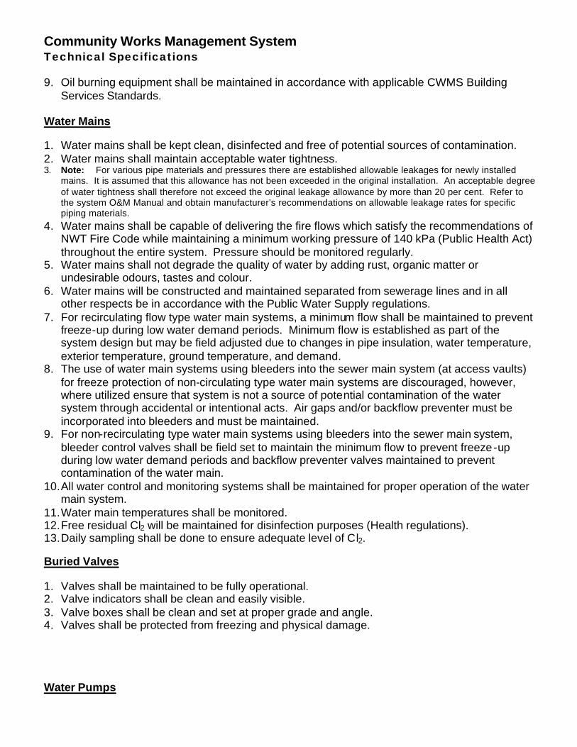
Community Works Management System Technical Specifications 9. Oil burning equipment shall be maintained in accordance with applicable CWMS Building
Services Standards. Water Mains 1. Water mains shall be kept clean, disinfected and free of potential sources of contamination. 2. Water mains shall maintain acceptable water tightness. 3. Note: For various pipe materials and pressures there are established allowable leakages for newly installed
mains. It is assumed that this allowance has not been exceeded in the original installation. An acceptable degree of water tightness shall therefore not exceed the original leakage allowance by more than 20 per cent. Refer to the system O&M Manual and obtain manufacturer’s recommendations on allowable leakage rates for specific piping materials.
4. Water mains shall be capable of delivering the fire flows which satisfy the recommendations of NWT Fire Code while maintaining a minimum working pressure of 140 kPa (Public Health Act) throughout the entire system. Pressure should be monitored regularly.
5. Water mains shall not degrade the quality of water by adding rust, organic matter or undesirable odours, tastes and colour.
6. Water mains will be constructed and maintained separated from sewerage lines and in all other respects be in accordance with the Public Water Supply regulations.
7. For recirculating flow type water main systems, a minimum flow shall be maintained to prevent freeze-up during low water demand periods. Minimum flow is established as part of the system design but may be field adjusted due to changes in pipe insulation, water temperature, exterior temperature, ground temperature, and demand.
8. The use of water main systems using bleeders into the sewer main system (at access vaults) for freeze protection of non-circulating type water main systems are discouraged, however, where utilized ensure that system is not a source of potential contamination of the water system through accidental or intentional acts. Air gaps and/or backflow preventer must be incorporated into bleeders and must be maintained.
9. For non-recirculating type water main systems using bleeders into the sewer main system, bleeder control valves shall be field set to maintain the minimum flow to prevent freeze-up during low water demand periods and backflow preventer valves maintained to prevent contamination of the water main.
10. All water control and monitoring systems shall be maintained for proper operation of the water main system.
11. Water main temperatures shall be monitored. 12. Free residual Cl2 will be maintained for disinfection purposes (Health regulations). 13. Daily sampling shall be done to ensure adequate level of Cl2. Buried Valves 1. Valves shall be maintained to be fully operational. 2. Valve indicators shall be clean and easily visible. 3. Valve boxes shall be clean and set at proper grade and angle. 4. Valves shall be protected from freezing and physical damage. Water Pumps
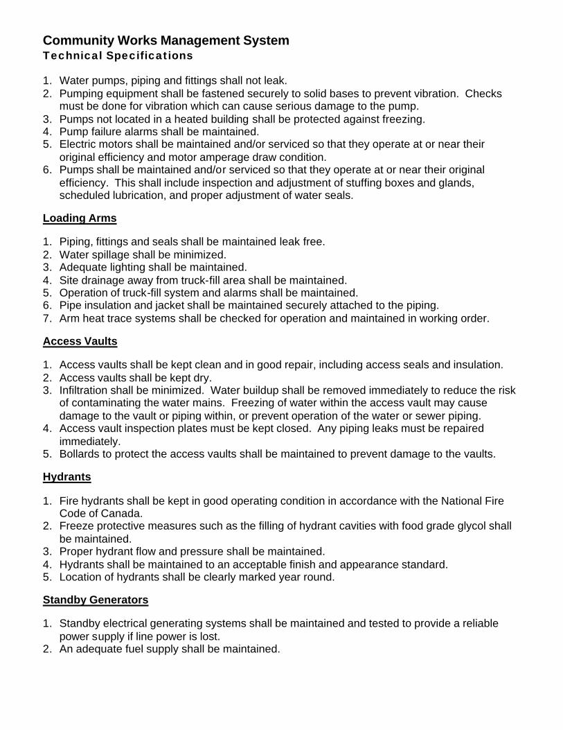
Community Works Management System Technical Specifications 1. Water pumps, piping and fittings shall not leak. 2. Pumping equipment shall be fastened securely to solid bases to prevent vibration. Checks
must be done for vibration which can cause serious damage to the pump. 3. Pumps not located in a heated building shall be protected against freezing. 4. Pump failure alarms shall be maintained. 5. Electric motors shall be maintained and/or serviced so that they operate at or near their
original efficiency and motor amperage draw condition. 6. Pumps shall be maintained and/or serviced so that they operate at or near their original
efficiency. This shall include inspection and adjustment of stuffing boxes and glands, scheduled lubrication, and proper adjustment of water seals.
Loading Arms 1. Piping, fittings and seals shall be maintained leak free. 2. Water spillage shall be minimized. 3. Adequate lighting shall be maintained. 4. Site drainage away from truck-fill area shall be maintained. 5. Operation of truck-fill system and alarms shall be maintained. 6. Pipe insulation and jacket shall be maintained securely attached to the piping. 7. Arm heat trace systems shall be checked for operation and maintained in working order.
Access Vaults
1. Access vaults shall be kept clean and in good repair, including access seals and insulation. 2. Access vaults shall be kept dry. 3. Infiltration shall be minimized. Water buildup shall be removed immediately to reduce the risk
of contaminating the water mains. Freezing of water within the access vault may cause damage to the vault or piping within, or prevent operation of the water or sewer piping.
4. Access vault inspection plates must be kept closed. Any piping leaks must be repaired immediately.
5. Bollards to protect the access vaults shall be maintained to prevent damage to the vaults. Hydrants 1. Fire hydrants shall be kept in good operating condition in accordance with the National Fire
Code of Canada. 2. Freeze protective measures such as the filling of hydrant cavities with food grade glycol shall
be maintained. 3. Proper hydrant flow and pressure shall be maintained. 4. Hydrants shall be maintained to an acceptable finish and appearance standard. 5. Location of hydrants shall be clearly marked year round. Standby Generators 1. Standby electrical generating systems shall be maintained and tested to provide a reliable
power supply if line power is lost. 2. An adequate fuel supply shall be maintained.
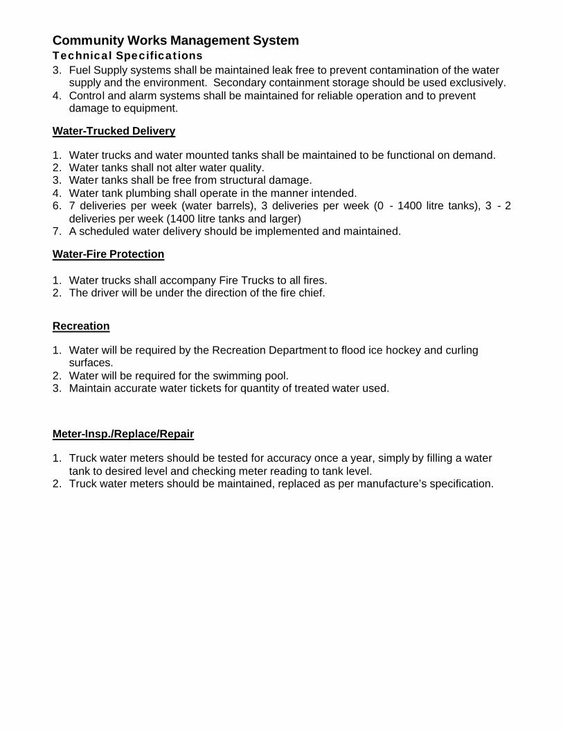
Community Works Management System Technical Specifications 3. Fuel Supply systems shall be maintained leak free to prevent contamination of the water
supply and the environment. Secondary containment storage should be used exclusively. 4. Control and alarm systems shall be maintained for reliable operation and to prevent
damage to equipment. Water-Trucked Delivery
1. Water trucks and water mounted tanks shall be maintained to be functional on demand. 2. Water tanks shall not alter water quality. 3. Water tanks shall be free from structural damage. 4. Water tank plumbing shall operate in the manner intended. 6. 7 deliveries per week (water barrels), 3 deliveries per week (0 - 1400 litre tanks), 3 - 2
deliveries per week (1400 litre tanks and larger) 7. A scheduled water delivery should be implemented and maintained. Water-Fire Protection 1. Water trucks shall accompany Fire Trucks to all fires. 2. The driver will be under the direction of the fire chief.
Recreation 1. Water will be required by the Recreation Department to flood ice hockey and curling
surfaces. 2. Water will be required for the swimming pool. 3. Maintain accurate water tickets for quantity of treated water used. Meter-Insp./Replace/Repair 1. Truck water meters should be tested for accuracy once a year, simply by filling a water
tank to desired level and checking meter reading to tank level. 2. Truck water meters should be maintained, replaced as per manufacture’s specification.
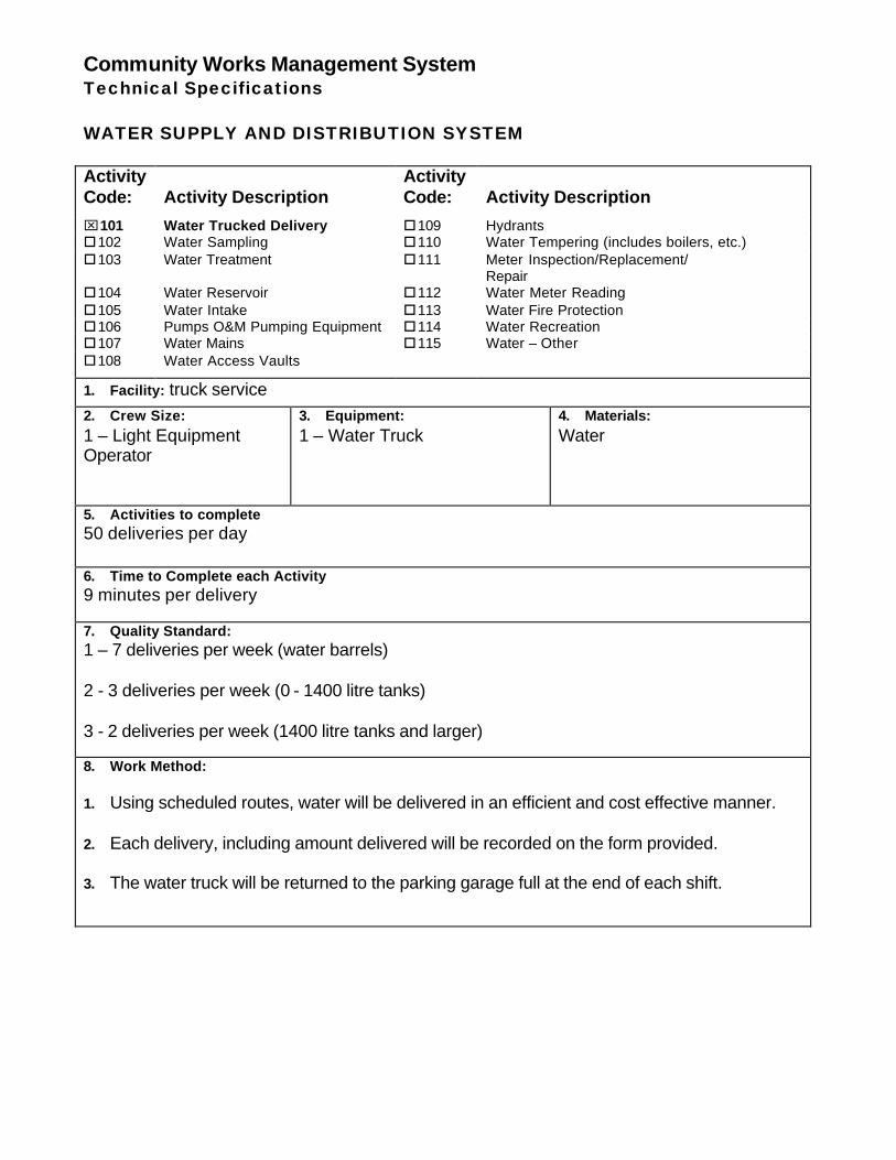
Community Works Management System Technical Specifications WATER SUPPLY AND DISTRIBUTION SYSTEM Activity Code:
Activity Description
Activity Code:
Activity Description
⌧101 Water Trucked Delivery o109 Hydrants o102 Water Sampling o110 Water Tempering (includes boilers, etc.) o103 Water Treatment o111 Meter Inspection/Replacement/
Repair o104 Water Reservoir o112 Water Meter Reading o105 Water Intake o113 Water Fire Protection o106 Pumps O&M Pumping Equipment o114 Water Recreation o107 Water Mains o115 Water – Other o108 Water Access Vaults
1. Facility: truck service 2. Crew Size: 1 – Light Equipment Operator
3. Equipment: 1 – Water Truck
4. Materials: Water
5. Activities to complete 50 deliveries per day
6. Time to Complete each Activity 9 minutes per delivery 7. Quality Standard: 1 – 7 deliveries per week (water barrels) 2 - 3 deliveries per week (0 - 1400 litre tanks) 3 - 2 deliveries per week (1400 litre tanks and larger) 8. Work Method: 1. Using scheduled routes, water will be delivered in an efficient and cost effective manner. 2. Each delivery, including amount delivered will be recorded on the form provided. 3. The water truck will be returned to the parking garage full at the end of each shift.
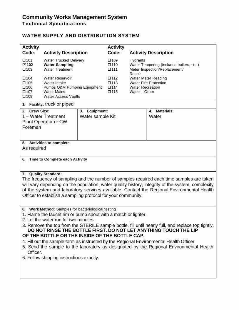
Community Works Management System Technical Specifications WATER SUPPLY AND DISTRIBUTION SYSTEM Activity Code:
Activity Description
Activity Code:
Activity Description
o101 Water Trucked Delivery o109 Hydrants ⌧102 Water Sampling o110 Water Tempering (includes boilers, etc.) o103 Water Treatment o111 Meter Inspection/Replacement/
Repair o104 Water Reservoir o112 Water Meter Reading o105 Water Intake o113 Water Fire Protection o106 Pumps O&M Pumping Equipment o114 Water Recreation o107 Water Mains o115 Water – Other o108 Water Access Vaults
1. Facility: truck or piped 2. Crew Size: 1 – Water Treatment Plant Operator or CW Foreman
3. Equipment: Water sample Kit
4. Materials: Water
5. Activities to complete As required
6. Time to Complete each Activity 7. Quality Standard: The frequency of sampling and the number of samples required each time samples are taken will vary depending on the population, water quality history, integrity of the system, complexity of the system and laboratory services available. Contact the Regional Environmental Health Officer to establish a sampling protocol for your community. 8. Work Method: Samples for bacteriological testing 1. Flame the faucet rim or pump spout with a match or lighter. 2. Let the water run for two minutes. 3. Remove the top from the STERILE sample bottle, fill until nearly full, and replace top tightly.
DO NOT RINSE THE BOTTLE FIRST. DO NOT LET ANYTHING TOUCH THE LIP OF THE BOTTLE OR THE INSIDE OF THE BOTTLE CAP. 4. Fill out the sample form as instructed by the Regional Environmental Health Officer. 5. Send the sample to the laboratory as designated by the Regional Environmental Health
Officer. 6. Follow shipping instructions exactly.
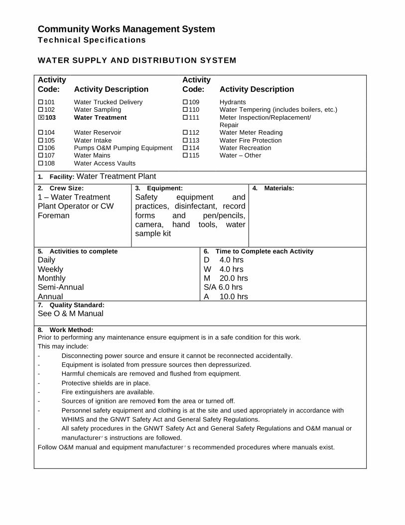
Community Works Management System Technical Specifications WATER SUPPLY AND DISTRIBUTION SYSTEM Activity Code:
Activity Description
Activity Code:
Activity Description
o101 Water Trucked Delivery o109 Hydrants o102 Water Sampling o110 Water Tempering (includes boilers, etc.) ⌧103 Water Treatment o111 Meter Inspection/Replacement/
Repair o104 Water Reservoir o112 Water Meter Reading o105 Water Intake o113 Water Fire Protection o106 Pumps O&M Pumping Equipment o114 Water Recreation o107 Water Mains o115 Water – Other o108 Water Access Vaults
1. Facility: Water Treatment Plant 2. Crew Size: 1 – Water Treatment Plant Operator or CW Foreman
3. Equipment: Safety equipment and practices, disinfectant, record forms and pen/pencils, camera, hand tools, water sample kit
4. Materials:
5. Activities to complete Daily Weekly Monthly Semi-Annual Annual
6. Time to Complete each Activity D 4.0 hrs W 4.0 hrs M 20.0 hrs S/A 6.0 hrs A 10.0 hrs
7. Quality Standard: See O & M Manual 8. Work Method: Prior to performing any maintenance ensure equipment is in a safe condition for this work. This may include: - Disconnecting power source and ensure it cannot be reconnected accidentally. - Equipment is isolated from pressure sources then depressurized. - Harmful chemicals are removed and flushed from equipment. - Protective shields are in place. - Fire extinguishers are available. - Sources of ignition are removed from the area or turned off. - Personnel safety equipment and clothing is at the site and used appropriately in accordance with
WHIMS and the GNWT Safety Act and General Safety Regulations. - All safety procedures in the GNWT Safety Act and General Safety Regulations and O&M manual or
manufacturer’s instructions are followed. Follow O&M manual and equipment manufacturer’s recommended procedures where manuals exist.
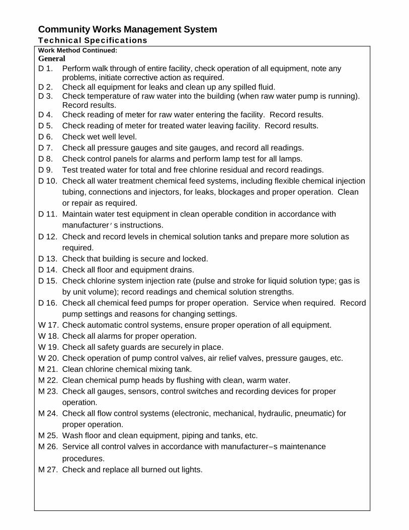
Community Works Management System Technical Specifications Work Method Continued: General D 1. Perform walk through of entire facility, check operation of all equipment, note any
problems, initiate corrective action as required. D 2. Check all equipment for leaks and clean up any spilled fluid. D 3. Check temperature of raw water into the building (when raw water pump is running).
Record results. D 4. Check reading of meter for raw water entering the facility. Record results. D 5. Check reading of meter for treated water leaving facility. Record results. D 6. Check wet well level. D 7. Check all pressure gauges and site gauges, and record all readings. D 8. Check control panels for alarms and perform lamp test for all lamps. D 9. Test treated water for total and free chlorine residual and record readings. D 10. Check all water treatment chemical feed systems, including flexible chemical injection
tubing, connections and injectors, for leaks, blockages and proper operation. Clean or repair as required.
D 11. Maintain water test equipment in clean operable condition in accordance with manufacturer’s instructions.
D 12. Check and record levels in chemical solution tanks and prepare more solution as required.
D 13. Check that building is secure and locked. D 14. Check all floor and equipment drains. D 15. Check chlorine system injection rate (pulse and stroke for liquid solution type; gas is
by unit volume); record readings and chemical solution strengths. D 16. Check all chemical feed pumps for proper operation. Service when required. Record
pump settings and reasons for changing settings. W 17. Check automatic control systems, ensure proper operation of all equipment. W 18. Check all alarms for proper operation. W 19. Check all safety guards are securely in place. W 20. Check operation of pump control valves, air relief valves, pressure gauges, etc. M 21. Clean chlorine chemical mixing tank. M 22. Clean chemical pump heads by flushing with clean, warm water. M 23. Check all gauges, sensors, control switches and recording devices for proper
operation. M 24. Check all flow control systems (electronic, mechanical, hydraulic, pneumatic) for
proper operation. M 25. Wash floor and clean equipment, piping and tanks, etc. M 26. Service all control valves in accordance with manufacturer=s maintenance
procedures. M 27. Check and replace all burned out lights.
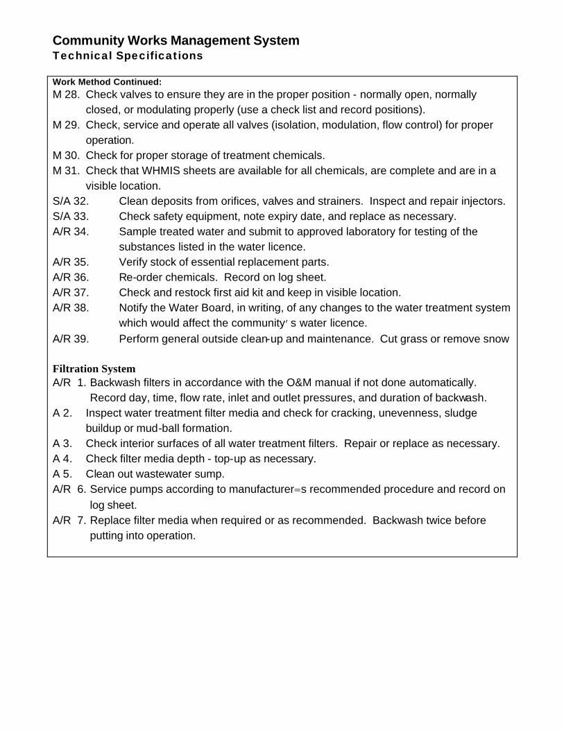
Community Works Management System Technical Specifications Work Method Continued: M 28. Check valves to ensure they are in the proper position - normally open, normally
closed, or modulating properly (use a check list and record positions). M 29. Check, service and operate all valves (isolation, modulation, flow control) for proper
operation. M 30. Check for proper storage of treatment chemicals. M 31. Check that WHMIS sheets are available for all chemicals, are complete and are in a
visible location. S/A 32. Clean deposits from orifices, valves and strainers. Inspect and repair injectors. S/A 33. Check safety equipment, note expiry date, and replace as necessary. A/R 34. Sample treated water and submit to approved laboratory for testing of the
substances listed in the water licence. A/R 35. Verify stock of essential replacement parts. A/R 36. Re-order chemicals. Record on log sheet. A/R 37. Check and restock first aid kit and keep in visible location. A/R 38. Notify the Water Board, in writing, of any changes to the water treatment system
which would affect the community’s water licence. A/R 39. Perform general outside clean-up and maintenance. Cut grass or remove snow
Filtration System A/R 1. Backwash filters in accordance with the O&M manual if not done automatically.
Record day, time, flow rate, inlet and outlet pressures, and duration of backwash. A 2. Inspect water treatment filter media and check for cracking, unevenness, sludge
buildup or mud-ball formation. A 3. Check interior surfaces of all water treatment filters. Repair or replace as necessary. A 4. Check filter media depth - top-up as necessary. A 5. Clean out wastewater sump. A/R 6. Service pumps according to manufacturer=s recommended procedure and record on
log sheet. A/R 7. Replace filter media when required or as recommended. Backwash twice before
putting into operation.
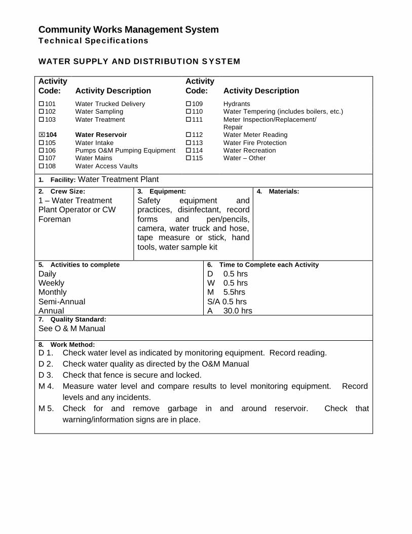
Community Works Management System Technical Specifications WATER SUPPLY AND DISTRIBUTION SYSTEM Activity Code:
Activity Description
Activity Code:
Activity Description
o101 Water Trucked Delivery o109 Hydrants o102 Water Sampling o110 Water Tempering (includes boilers, etc.) o103 Water Treatment o111 Meter Inspection/Replacement/
Repair ⌧104 Water Reservoir o112 Water Meter Reading o105 Water Intake o113 Water Fire Protection o106 Pumps O&M Pumping Equipment o114 Water Recreation o107 Water Mains o115 Water – Other o108 Water Access Vaults
1. Facility: Water Treatment Plant 2. Crew Size: 1 – Water Treatment Plant Operator or CW Foreman
3. Equipment: Safety equipment and practices, disinfectant, record forms and pen/pencils, camera, water truck and hose, tape measure or stick, hand tools, water sample kit
4. Materials:
5. Activities to complete Daily Weekly Monthly Semi-Annual Annual
6. Time to Complete each Activity D 0.5 hrs W 0.5 hrs M 5.5hrs S/A 0.5 hrs A 30.0 hrs
7. Quality Standard: See O & M Manual 8. Work Method: D 1. Check water level as indicated by monitoring equipment. Record reading. D 2. Check water quality as directed by the O&M Manual D 3. Check that fence is secure and locked. M 4. Measure water level and compare results to level monitoring equipment. Record
levels and any incidents. M 5. Check for and remove garbage in and around reservoir. Check that
warning/information signs are in place.
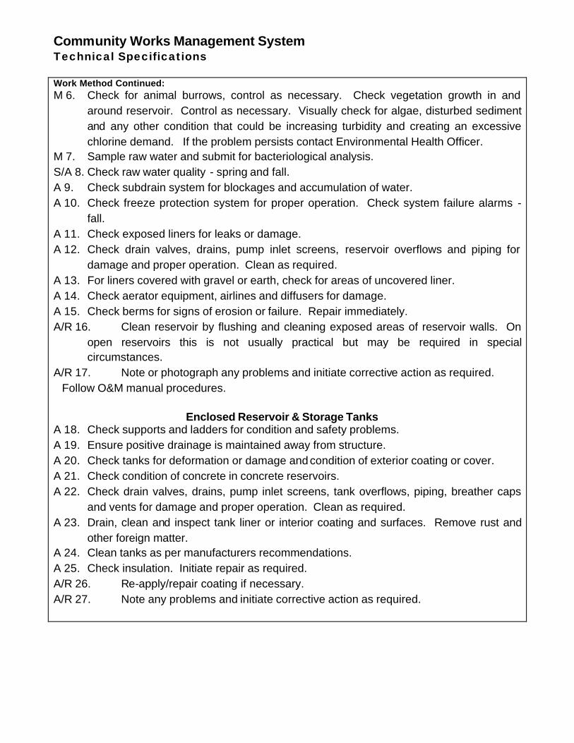
Community Works Management System Technical Specifications Work Method Continued: M 6. Check for animal burrows, control as necessary. Check vegetation growth in and
around reservoir. Control as necessary. Visually check for algae, disturbed sediment and any other condition that could be increasing turbidity and creating an excessive chlorine demand. If the problem persists contact Environmental Health Officer.
M 7. Sample raw water and submit for bacteriological analysis. S/A 8. Check raw water quality - spring and fall. A 9. Check subdrain system for blockages and accumulation of water. A 10. Check freeze protection system for proper operation. Check system failure alarms -
fall. A 11. Check exposed liners for leaks or damage. A 12. Check drain valves, drains, pump inlet screens, reservoir overflows and piping for
damage and proper operation. Clean as required. A 13. For liners covered with gravel or earth, check for areas of uncovered liner. A 14. Check aerator equipment, airlines and diffusers for damage. A 15. Check berms for signs of erosion or failure. Repair immediately. A/R 16. Clean reservoir by flushing and cleaning exposed areas of reservoir walls. On
open reservoirs this is not usually practical but may be required in special circumstances.
A/R 17. Note or photograph any problems and initiate corrective action as required. Follow O&M manual procedures.
Enclosed Reservoir & Storage Tanks A 18. Check supports and ladders for condition and safety problems. A 19. Ensure positive drainage is maintained away from structure. A 20. Check tanks for deformation or damage and condition of exterior coating or cover. A 21. Check condition of concrete in concrete reservoirs. A 22. Check drain valves, drains, pump inlet screens, tank overflows, piping, breather caps
and vents for damage and proper operation. Clean as required. A 23. Drain, clean and inspect tank liner or interior coating and surfaces. Remove rust and
other foreign matter. A 24. Clean tanks as per manufacturers recommendations. A 25. Check insulation. Initiate repair as required. A/R 26. Re-apply/repair coating if necessary. A/R 27. Note any problems and initiate corrective action as required.
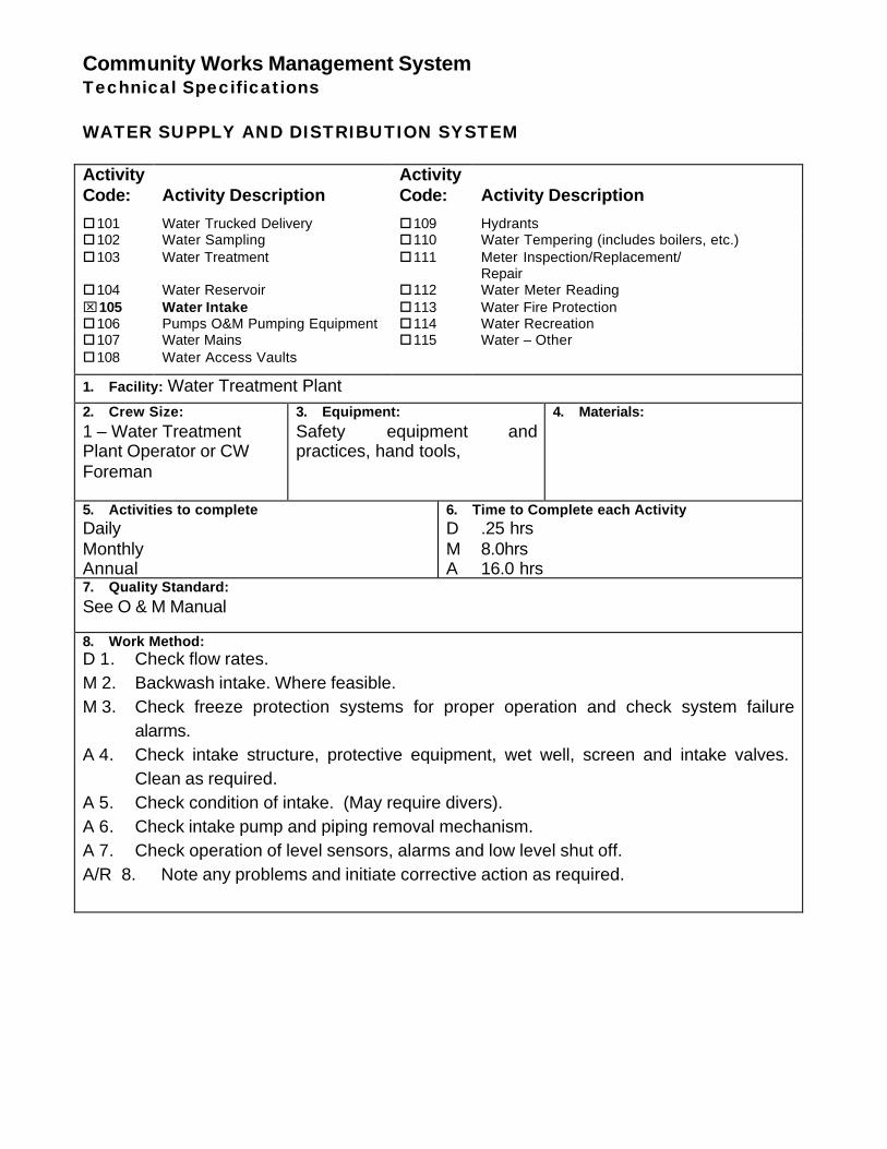
Community Works Management System Technical Specifications WATER SUPPLY AND DISTRIBUTION SYSTEM Activity Code:
Activity Description
Activity Code:
Activity Description
o101 Water Trucked Delivery o109 Hydrants o102 Water Sampling o110 Water Tempering (includes boilers, etc.) o103 Water Treatment o111 Meter Inspection/Replacement/
Repair o104 Water Reservoir o112 Water Meter Reading ⌧105 Water Intake o113 Water Fire Protection o106 Pumps O&M Pumping Equipment o114 Water Recreation o107 Water Mains o115 Water – Other o108 Water Access Vaults
1. Facility: Water Treatment Plant 2. Crew Size: 1 – Water Treatment Plant Operator or CW Foreman
3. Equipment: Safety equipment and practices, hand tools,
4. Materials:
5. Activities to complete Daily Monthly Annual
6. Time to Complete each Activity D .25 hrs M 8.0hrs A 16.0 hrs
7. Quality Standard: See O & M Manual 8. Work Method: D 1. Check flow rates. M 2. Backwash intake. Where feasible. M 3. Check freeze protection systems for proper operation and check system failure
alarms. A 4. Check intake structure, protective equipment, wet well, screen and intake valves.
Clean as required. A 5. Check condition of intake. (May require divers). A 6. Check intake pump and piping removal mechanism. A 7. Check operation of level sensors, alarms and low level shut off. A/R 8. Note any problems and initiate corrective action as required.
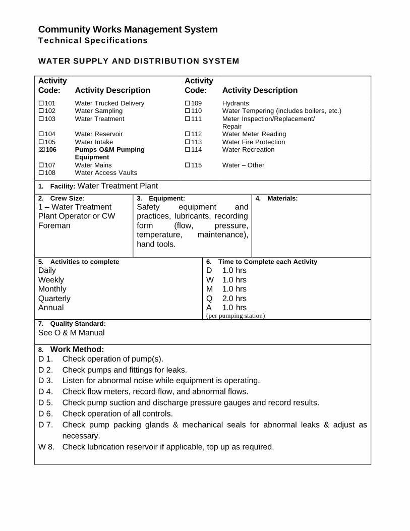
Community Works Management System Technical Specifications WATER SUPPLY AND DISTRIBUTION SYSTEM Activity Code:
Activity Description
Activity Code:
Activity Description
o101 Water Trucked Delivery o109 Hydrants o102 Water Sampling o110 Water Tempering (includes boilers, etc.) o103 Water Treatment o111 Meter Inspection/Replacement/
Repair o104 Water Reservoir o112 Water Meter Reading o105 Water Intake o113 Water Fire Protection ⌧106 Pumps O&M Pumping
Equipment o114 Water Recreation
o107 Water Mains o115 Water – Other o108 Water Access Vaults
1. Facility: Water Treatment Plant 2. Crew Size: 1 – Water Treatment Plant Operator or CW Foreman
3. Equipment: Safety equipment and practices, lubricants, recording form (flow, pressure, temperature, maintenance), hand tools.
4. Materials:
5. Activities to complete Daily Weekly Monthly Quarterly Annual
6. Time to Complete each Activity D 1.0 hrs W 1.0 hrs M 1.0 hrs Q 2.0 hrs A 1.0 hrs (per pumping station)
7. Quality Standard: See O & M Manual 8. Work Method: D 1. Check operation of pump(s). D 2. Check pumps and fittings for leaks. D 3. Listen for abnormal noise while equipment is operating. D 4. Check flow meters, record flow, and abnormal flows. D 5. Check pump suction and discharge pressure gauges and record results. D 6. Check operation of all controls. D 7. Check pump packing glands & mechanical seals for abnormal leaks & adjust as
necessary. W 8. Check lubrication reservoir if applicable, top up as required.
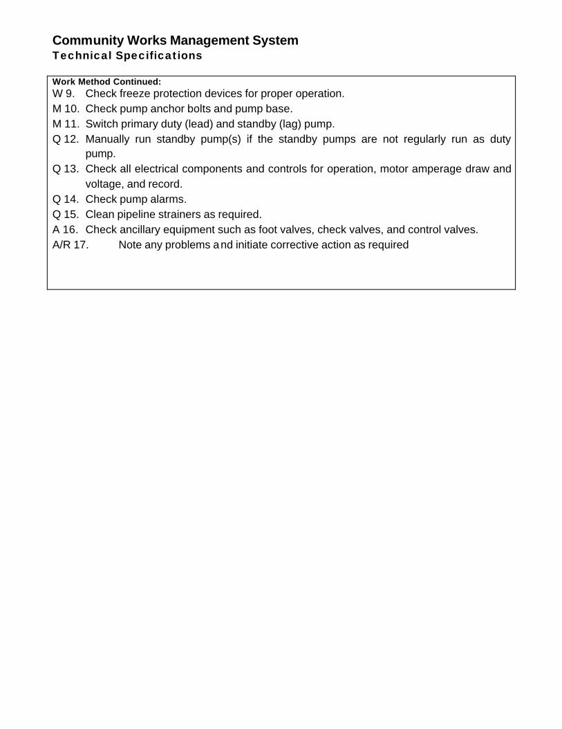
Community Works Management System Technical Specifications Work Method Continued: W 9. Check freeze protection devices for proper operation. M 10. Check pump anchor bolts and pump base. M 11. Switch primary duty (lead) and standby (lag) pump. Q 12. Manually run standby pump(s) if the standby pumps are not regularly run as duty
pump. Q 13. Check all electrical components and controls for operation, motor amperage draw and
voltage, and record. Q 14. Check pump alarms. Q 15. Clean pipeline strainers as required. A 16. Check ancillary equipment such as foot valves, check valves, and control valves. A/R 17. Note any problems and initiate corrective action as required
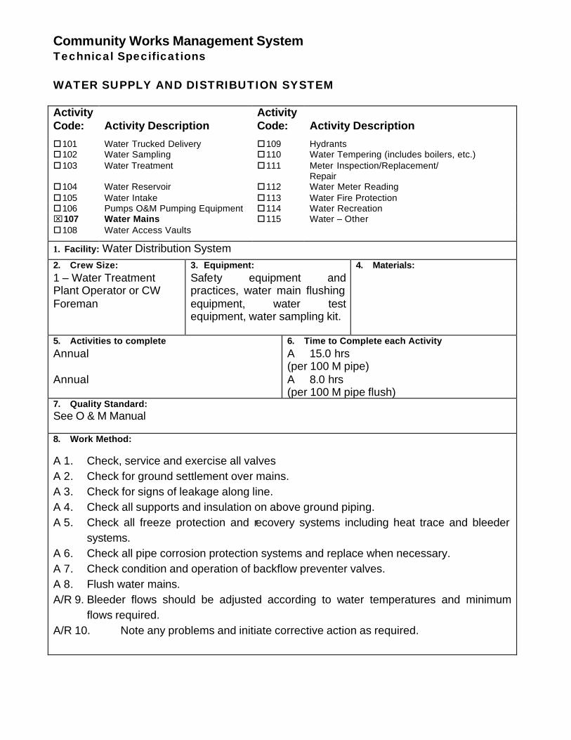
Community Works Management System Technical Specifications WATER SUPPLY AND DISTRIBUTION SYSTEM Activity Code:
Activity Description
Activity Code:
Activity Description
o101 Water Trucked Delivery o109 Hydrants o102 Water Sampling o110 Water Tempering (includes boilers, etc.) o103 Water Treatment o111 Meter Inspection/Replacement/
Repair o104 Water Reservoir o112 Water Meter Reading o105 Water Intake o113 Water Fire Protection o106 Pumps O&M Pumping Equipment o114 Water Recreation ⌧107 Water Mains o115 Water – Other o108 Water Access Vaults
1. Facility: Water Distribution System 2. Crew Size: 1 – Water Treatment Plant Operator or CW Foreman
3. Equipment: Safety equipment and practices, water main flushing equipment, water test equipment, water sampling kit.
4. Materials:
5. Activities to complete Annual Annual
6. Time to Complete each Activity A 15.0 hrs (per 100 M pipe) A 8.0 hrs (per 100 M pipe flush)
7. Quality Standard: See O & M Manual 8. Work Method: A 1. Check, service and exercise all valves A 2. Check for ground settlement over mains. A 3. Check for signs of leakage along line. A 4. Check all supports and insulation on above ground piping. A 5. Check all freeze protection and recovery systems including heat trace and bleeder
systems. A 6. Check all pipe corrosion protection systems and replace when necessary. A 7. Check condition and operation of backflow preventer valves. A 8. Flush water mains. A/R 9. Bleeder flows should be adjusted according to water temperatures and minimum
flows required. A/R 10. Note any problems and initiate corrective action as required.
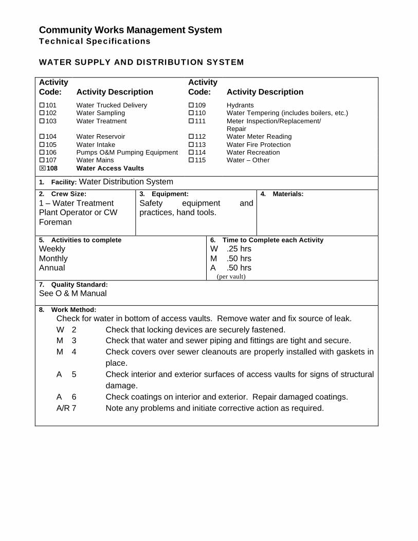
Community Works Management System Technical Specifications WATER SUPPLY AND DISTRIBUTION SYSTEM Activity Code:
Activity Description
Activity Code:
Activity Description
o101 Water Trucked Delivery o109 Hydrants o102 Water Sampling o110 Water Tempering (includes boilers, etc.) o103 Water Treatment o111 Meter Inspection/Replacement/
Repair o104 Water Reservoir o112 Water Meter Reading o105 Water Intake o113 Water Fire Protection o106 Pumps O&M Pumping Equipment o114 Water Recreation o107 Water Mains o115 Water – Other ⌧108 Water Access Vaults
1. Facility: Water Distribution System 2. Crew Size: 1 – Water Treatment Plant Operator or CW Foreman
3. Equipment: Safety equipment and practices, hand tools.
4. Materials:
5. Activities to complete Weekly Monthly Annual
6. Time to Complete each Activity W .25 hrs M .50 hrs A .50 hrs (per vault)
7. Quality Standard: See O & M Manual 8. Work Method:
Check for water in bottom of access vaults. Remove water and fix source of leak. W 2 Check that locking devices are securely fastened. M 3 Check that water and sewer piping and fittings are tight and secure. M 4 Check covers over sewer cleanouts are properly installed with gaskets in
place. A 5 Check interior and exterior surfaces of access vaults for signs of structural
damage. A 6 Check coatings on interior and exterior. Repair damaged coatings. A/R 7 Note any problems and initiate corrective action as required.
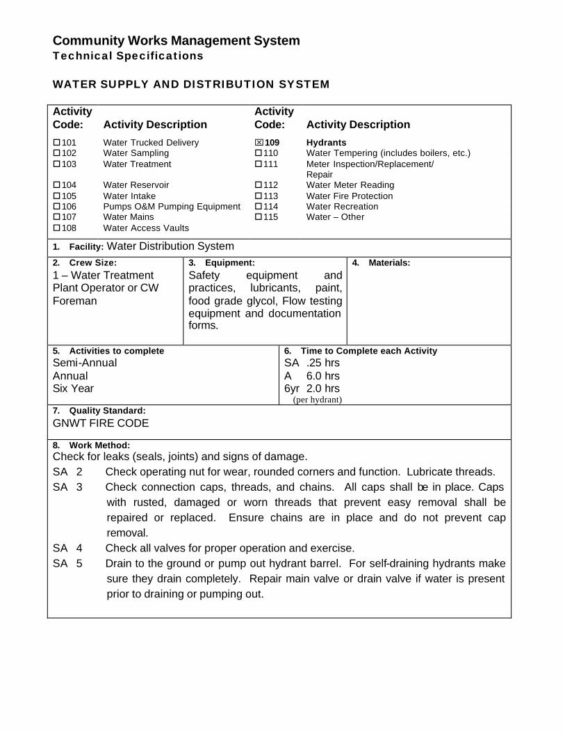
Community Works Management System Technical Specifications WATER SUPPLY AND DISTRIBUTION SYSTEM Activity Code:
Activity Description
Activity Code:
Activity Description
o101 Water Trucked Delivery ⌧109 Hydrants o102 Water Sampling o110 Water Tempering (includes boilers, etc.) o103 Water Treatment o111 Meter Inspection/Replacement/
Repair o104 Water Reservoir o112 Water Meter Reading o105 Water Intake o113 Water Fire Protection o106 Pumps O&M Pumping Equipment o114 Water Recreation o107 Water Mains o115 Water – Other o108 Water Access Vaults
1. Facility: Water Distribution System 2. Crew Size: 1 – Water Treatment Plant Operator or CW Foreman
3. Equipment: Safety equipment and practices, lubricants, paint, food grade glycol, Flow testing equipment and documentation forms.
4. Materials:
5. Activities to complete Semi-Annual Annual Six Year
6. Time to Complete each Activity SA .25 hrs A 6.0 hrs 6yr 2.0 hrs (per hydrant)
7. Quality Standard: GNWT FIRE CODE 8. Work Method: Check for leaks (seals, joints) and signs of damage. SA 2 Check operating nut for wear, rounded corners and function. Lubricate threads. SA 3 Check connection caps, threads, and chains. All caps shall be in place. Caps
with rusted, damaged or worn threads that prevent easy removal shall be repaired or replaced. Ensure chains are in place and do not prevent cap removal.
SA 4 Check all valves for proper operation and exercise. SA 5 Drain to the ground or pump out hydrant barrel. For self-draining hydrants make
sure they drain completely. Repair main valve or drain valve if water is present prior to draining or pumping out.
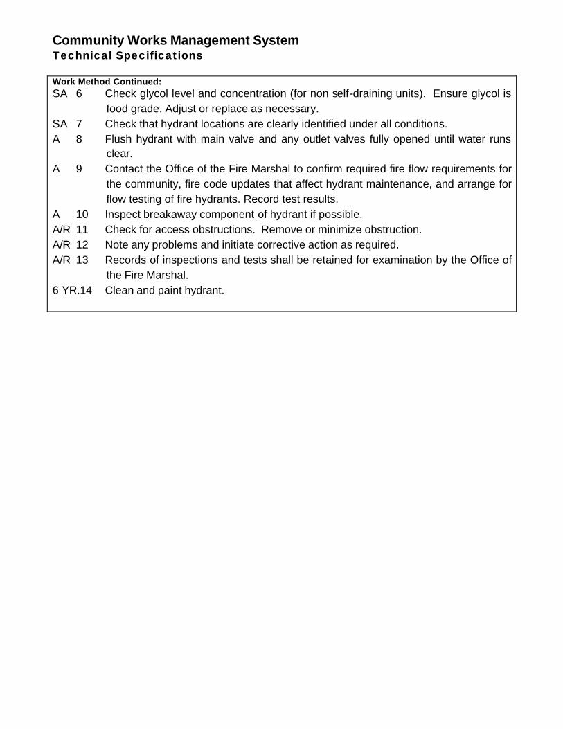
Community Works Management System Technical Specifications Work Method Continued: SA 6 Check glycol level and concentration (for non self-draining units). Ensure glycol is
food grade. Adjust or replace as necessary. SA 7 Check that hydrant locations are clearly identified under all conditions. A 8 Flush hydrant with main valve and any outlet valves fully opened until water runs
clear. A 9 Contact the Office of the Fire Marshal to confirm required fire flow requirements for
the community, fire code updates that affect hydrant maintenance, and arrange for flow testing of fire hydrants. Record test results.
A 10 Inspect breakaway component of hydrant if possible. A/R 11 Check for access obstructions. Remove or minimize obstruction. A/R 12 Note any problems and initiate corrective action as required. A/R 13 Records of inspections and tests shall be retained for examination by the Office of
the Fire Marshal. 6 YR.14 Clean and paint hydrant.
Community Works Management System Technical Specifications WATER SUPPLY AND DISTRIBUTION SYSTEM Activity Code:
Activity Description
Activity Code:
Activity Description
o101 Water Trucked Delivery o109 Hydrants o102 Water Sampling ⌧110 Water Tempering (includes boilers, etc.) o103 Water Treatment o111 Meter Inspection/Replacement/
Repair o104 Water Reservoir o112 Water Meter Reading o105 Water Intake o113 Water Fire Protection o106 Pumps O&M Pumping Equipment o114 Water Recreation o107 Water Mains o115 Water – Other o108 Water Access Vaults
1. Facility: 2. Crew Size:
3. Equipment:
4. Materials:
5. Activities to complete
6. Time to Complete each Activity
7. Quality Standard: 8. Work Method:
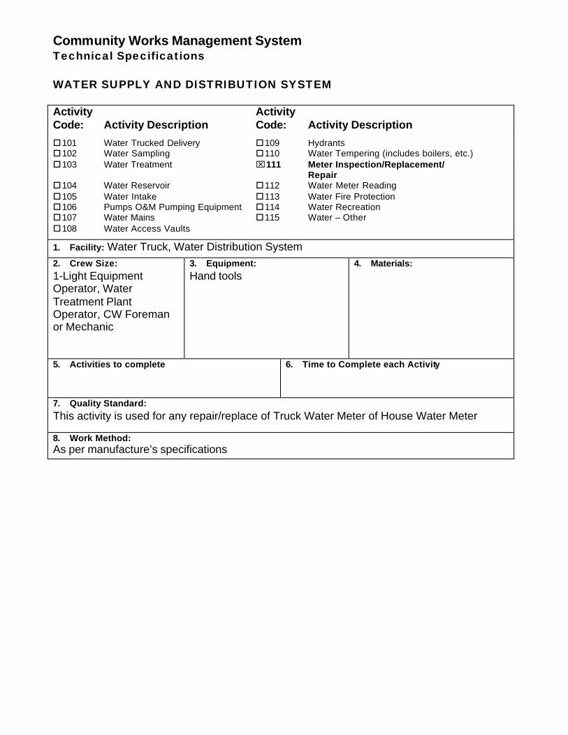
Community Works Management System Technical Specifications WATER SUPPLY AND DISTRIBUTION SYSTEM Activity Code:
Activity Description
Activity Code:
Activity Description
o101 Water Trucked Delivery o109 Hydrants o102 Water Sampling o110 Water Tempering (includes boilers, etc.) o103 Water Treatment ⌧111 Meter Inspection/Replacement/
Repair o104 Water Reservoir o112 Water Meter Reading o105 Water Intake o113 Water Fire Protection o106 Pumps O&M Pumping Equipment o114 Water Recreation o107 Water Mains o115 Water – Other o108 Water Access Vaults
1. Facility: Water Truck, Water Distribution System 2. Crew Size: 1-Light Equipment Operator, Water Treatment Plant Operator, CW Foreman or Mechanic
3. Equipment: Hand tools
4. Materials:
5. Activities to complete
6. Time to Complete each Activity
7. Quality Standard: This activity is used for any repair/replace of Truck Water Meter of House Water Meter 8. Work Method: As per manufacture’s specifications
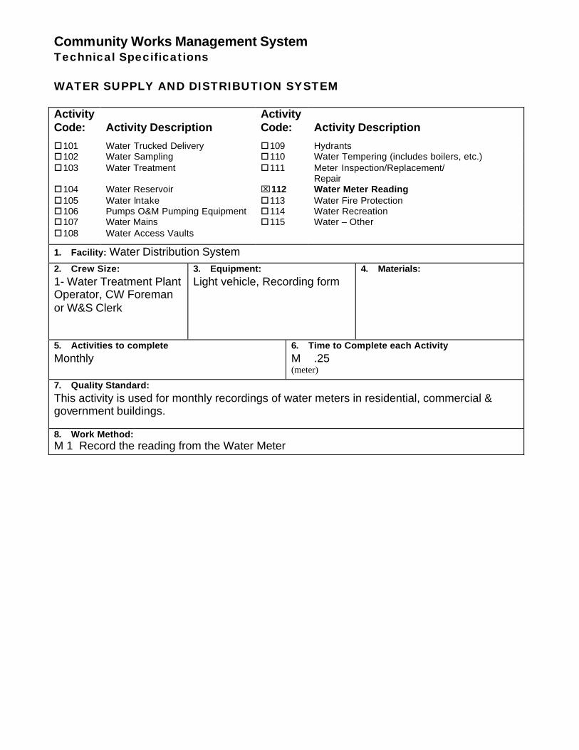
Community Works Management System Technical Specifications WATER SUPPLY AND DISTRIBUTION SYSTEM Activity Code:
Activity Description
Activity Code:
Activity Description
o101 Water Trucked Delivery o109 Hydrants o102 Water Sampling o110 Water Tempering (includes boilers, etc.) o103 Water Treatment o111 Meter Inspection/Replacement/
Repair o104 Water Reservoir ⌧112 Water Meter Reading o105 Water Intake o113 Water Fire Protection o106 Pumps O&M Pumping Equipment o114 Water Recreation o107 Water Mains o115 Water – Other o108 Water Access Vaults
1. Facility: Water Distribution System 2. Crew Size: 1- Water Treatment Plant Operator, CW Foreman or W&S Clerk
3. Equipment: Light vehicle, Recording form
4. Materials:
5. Activities to complete Monthly
6. Time to Complete each Activity M .25 (meter)
7. Quality Standard: This activity is used for monthly recordings of water meters in residential, commercial & government buildings. 8. Work Method: M 1 Record the reading from the Water Meter
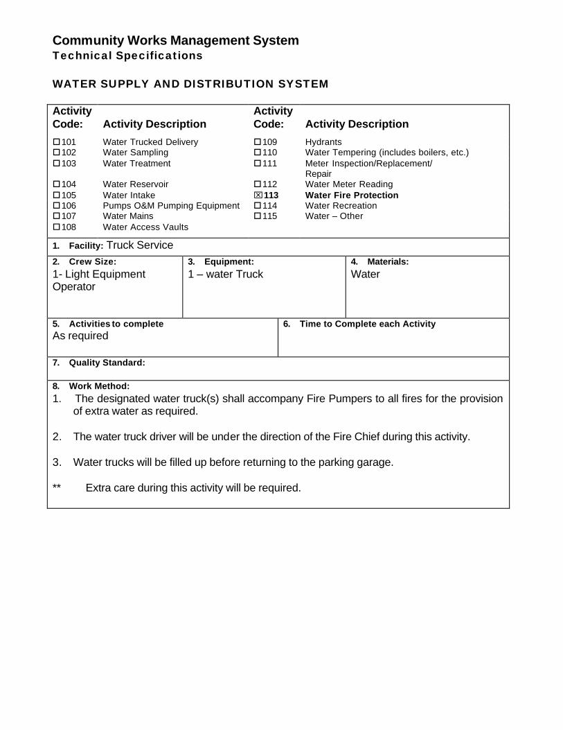
Community Works Management System Technical Specifications WATER SUPPLY AND DISTRIBUTION SYSTEM Activity Code:
Activity Description
Activity Code:
Activity Description
o101 Water Trucked Delivery o109 Hydrants o102 Water Sampling o110 Water Tempering (includes boilers, etc.) o103 Water Treatment o111 Meter Inspection/Replacement/
Repair o104 Water Reservoir o112 Water Meter Reading o105 Water Intake ⌧113 Water Fire Protection o106 Pumps O&M Pumping Equipment o114 Water Recreation o107 Water Mains o115 Water – Other o108 Water Access Vaults
1. Facility: Truck Service 2. Crew Size: 1- Light Equipment Operator
3. Equipment: 1 – water Truck
4. Materials: Water
5. Activities to complete As required
6. Time to Complete each Activity
7. Quality Standard: 8. Work Method: 1. The designated water truck(s) shall accompany Fire Pumpers to all fires for the provision
of extra water as required. 2. The water truck driver will be under the direction of the Fire Chief during this activity. 3. Water trucks will be filled up before returning to the parking garage. ** Extra care during this activity will be required.
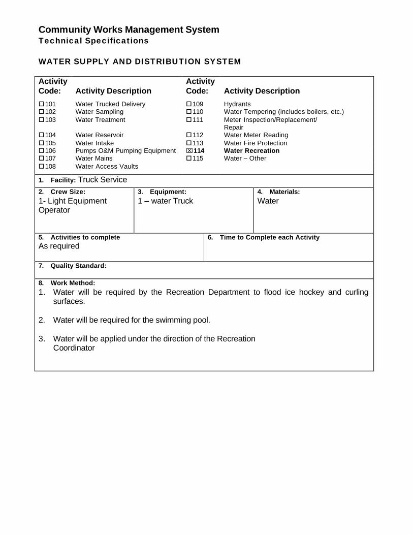
Community Works Management System Technical Specifications WATER SUPPLY AND DISTRIBUTION SYSTEM Activity Code:
Activity Description
Activity Code:
Activity Description
o101 Water Trucked Delivery o109 Hydrants o102 Water Sampling o110 Water Tempering (includes boilers, etc.) o103 Water Treatment o111 Meter Inspection/Replacement/
Repair o104 Water Reservoir o112 Water Meter Reading o105 Water Intake o113 Water Fire Protection o106 Pumps O&M Pumping Equipment ⌧114 Water Recreation o107 Water Mains o115 Water – Other o108 Water Access Vaults
1. Facility: Truck Service 2. Crew Size: 1- Light Equipment Operator
3. Equipment: 1 – water Truck
4. Materials: Water
5. Activities to complete As required
6. Time to Complete each Activity
7. Quality Standard: 8. Work Method: 1. Water will be required by the Recreation Department to flood ice hockey and curling
surfaces. 2. Water will be required for the swimming pool. 3. Water will be applied under the direction of the Recreation Coordinator
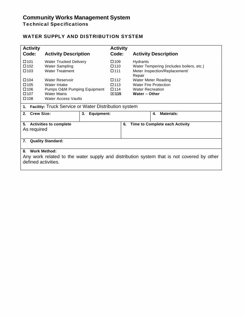
Community Works Management System Technical Specifications WATER SUPPLY AND DISTRIBUTION SYSTEM Activity Code:
Activity Description
Activity Code:
Activity Description
o101 Water Trucked Delivery o109 Hydrants o102 Water Sampling o110 Water Tempering (includes boilers, etc.) o103 Water Treatment o111 Meter Inspection/Replacement/
Repair o104 Water Reservoir o112 Water Meter Reading o105 Water Intake o113 Water Fire Protection o106 Pumps O&M Pumping Equipment o114 Water Recreation o107 Water Mains ⌧115 Water – Other o108 Water Access Vaults
1. Facility: Truck Service or Water Distribution system 2. Crew Size:
3. Equipment:
4. Materials:
5. Activities to complete As required
6. Time to Complete each Activity
7. Quality Standard: 8. Work Method: Any work related to the water supply and distribution system that is not covered by other defined activities.

ADDENDUM E
ABC NEED-TO-KNOW CRITERIA
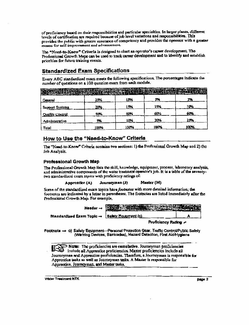
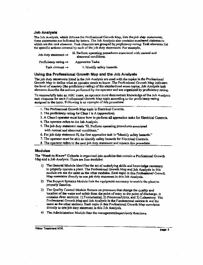
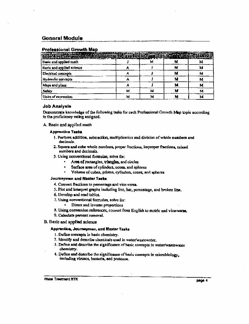
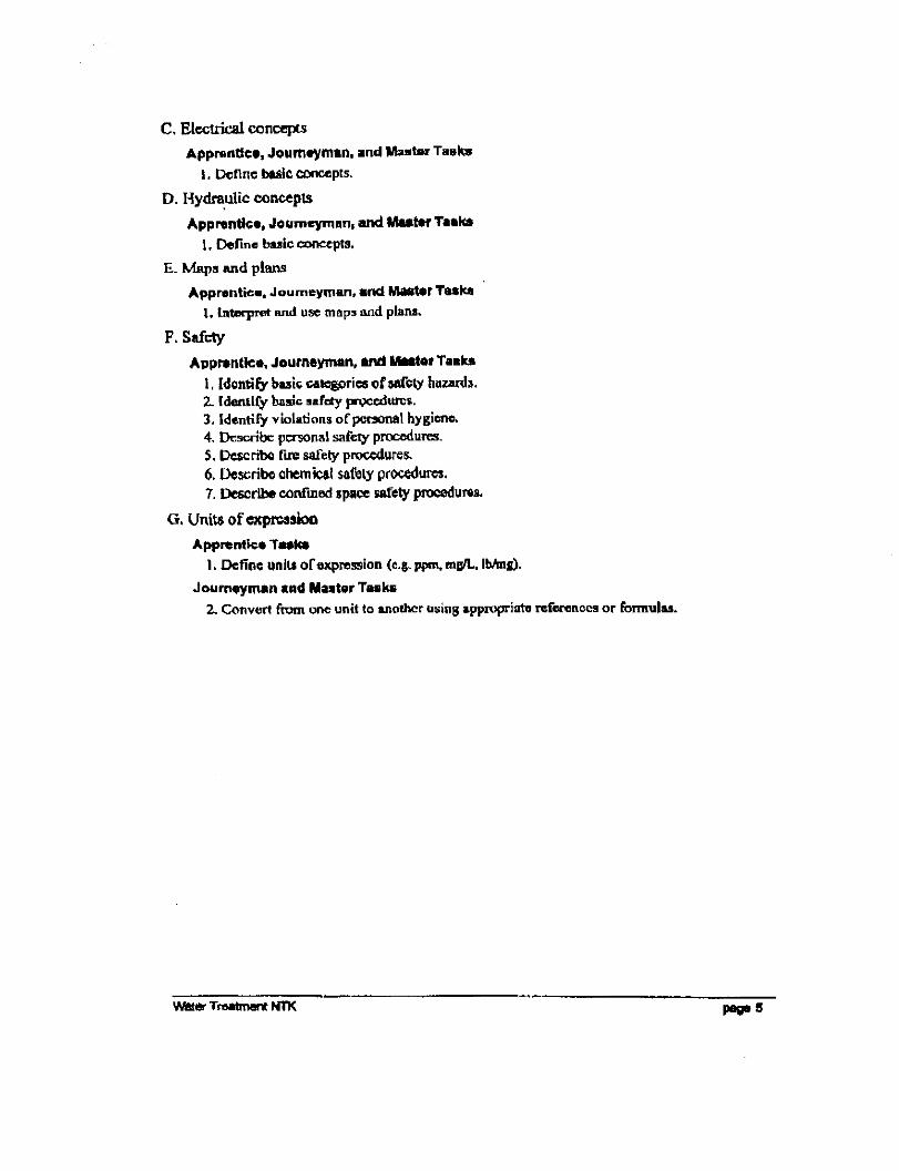
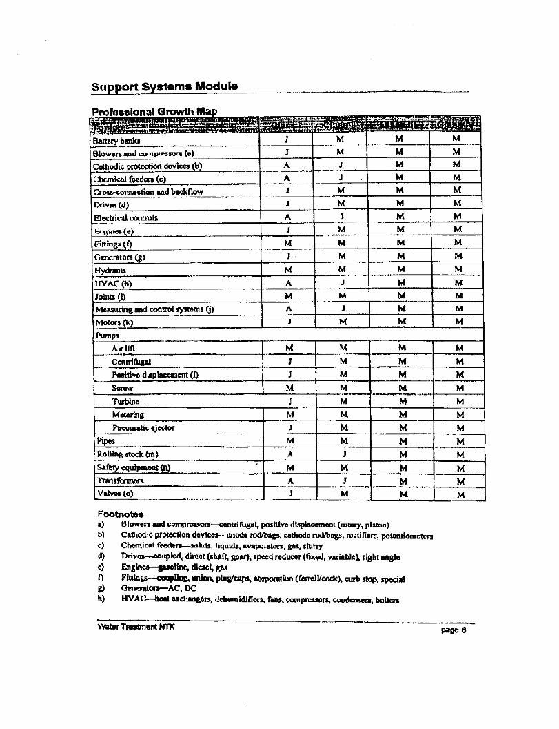
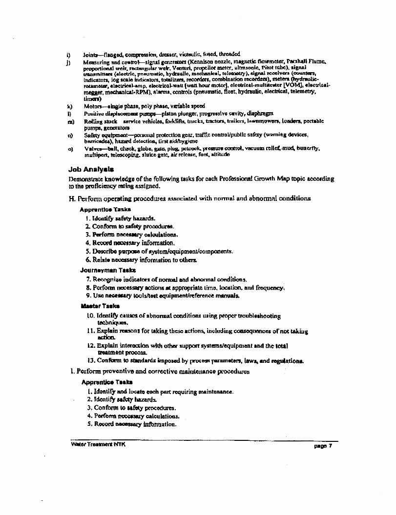
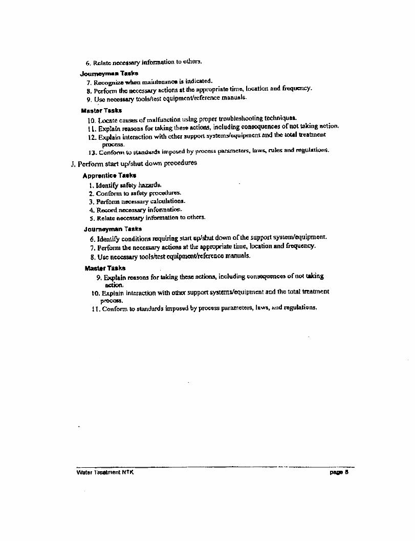
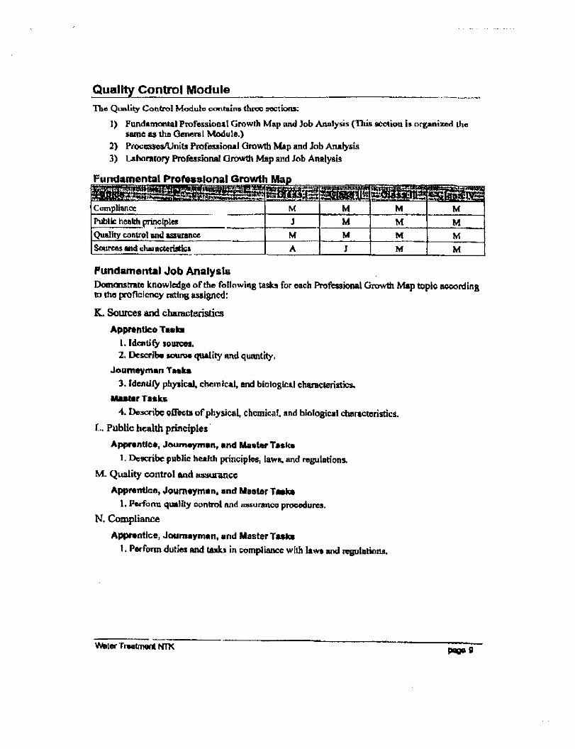
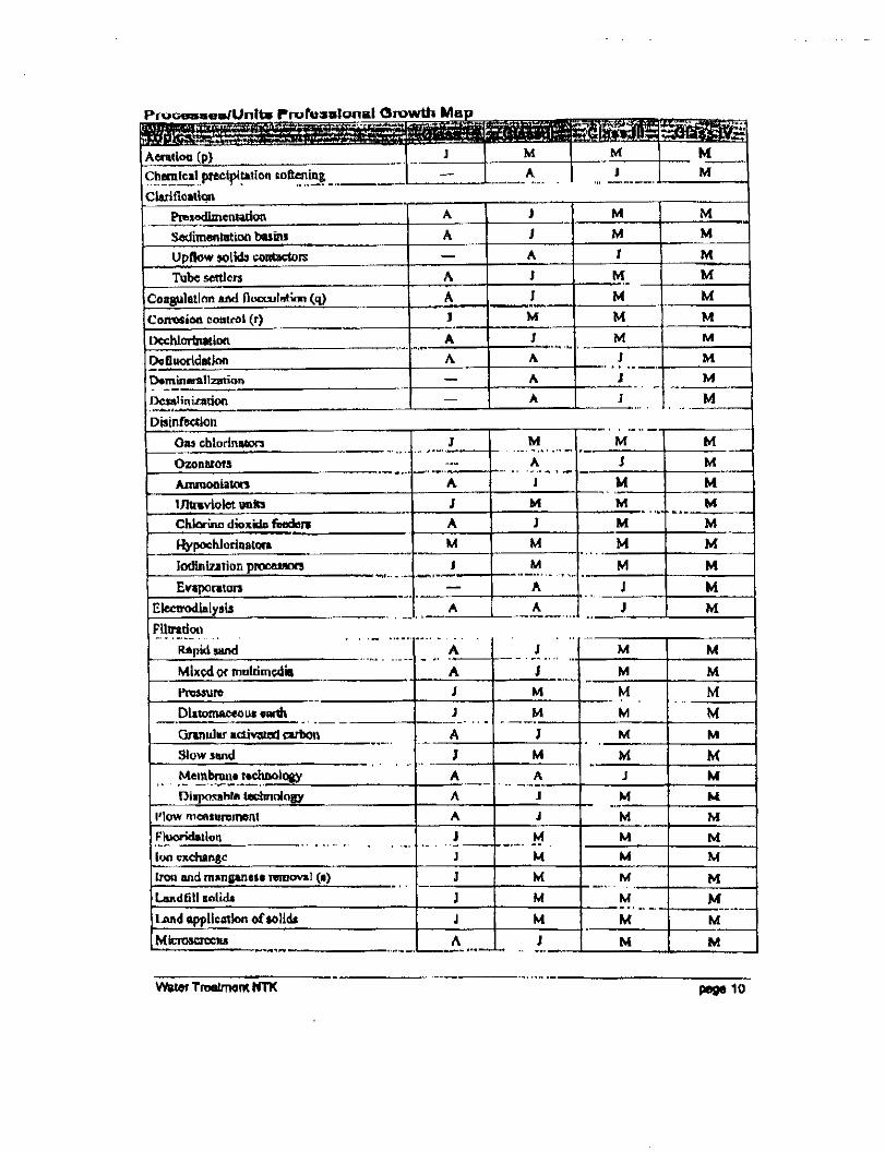
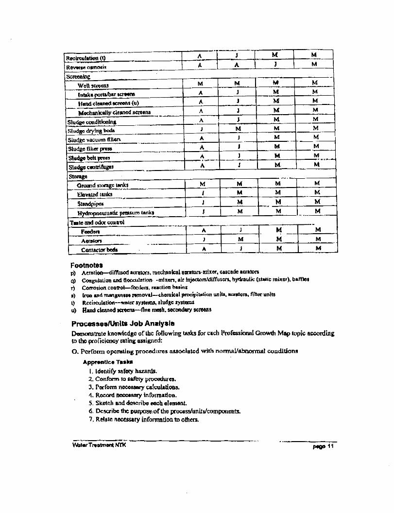
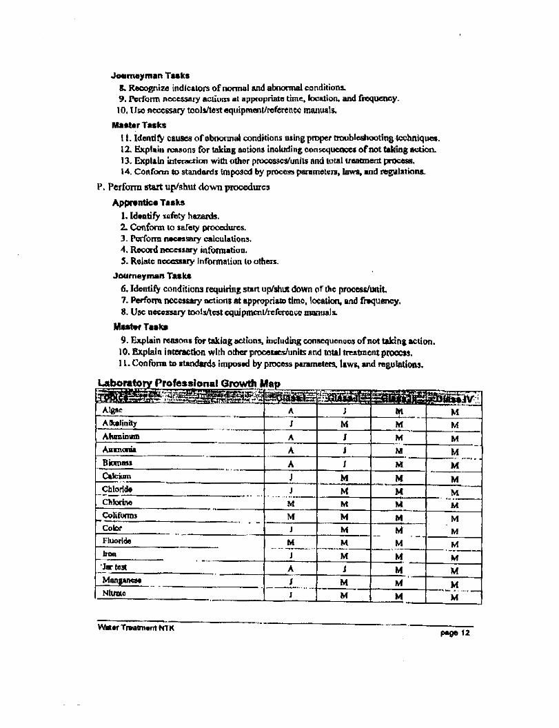
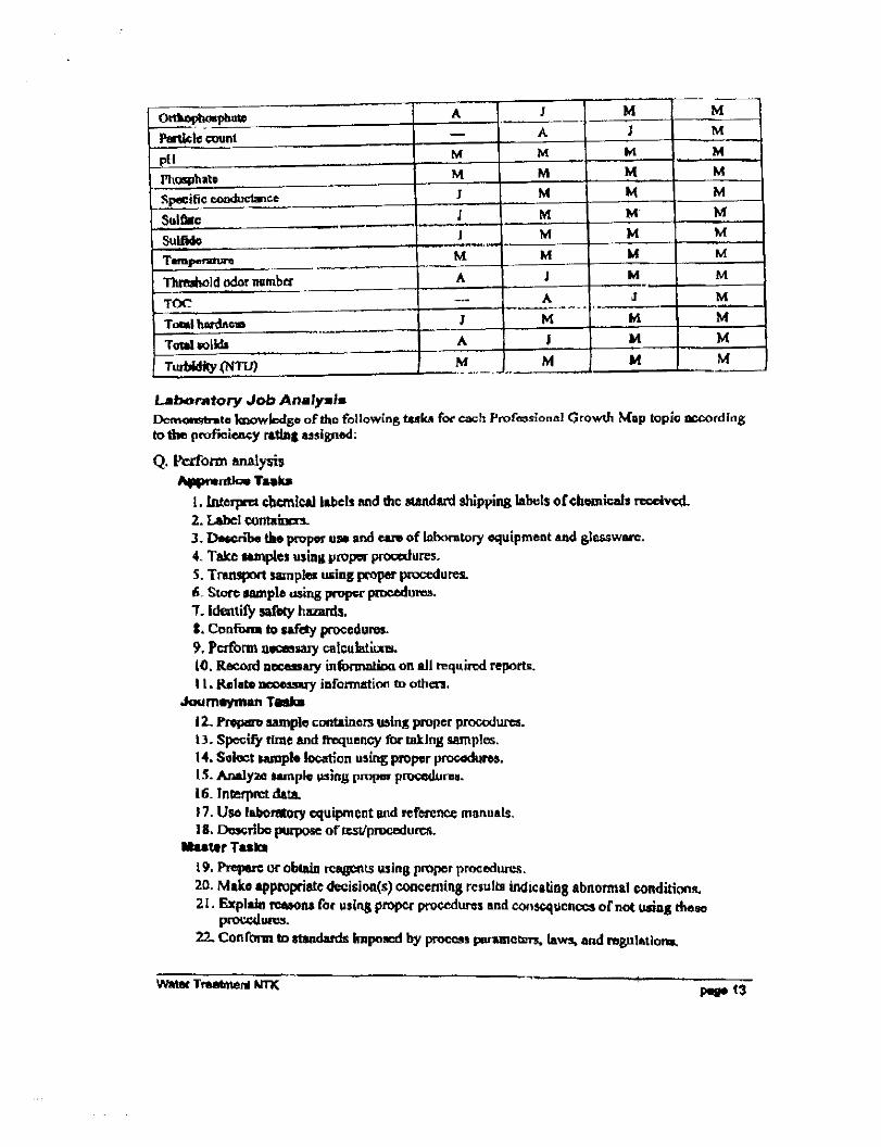
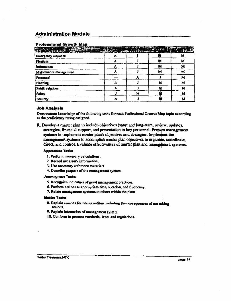

ADDENDUM F
ADDITIONAL SOURCES OF INFORMATION

Contacts & Additional Sources of Information
Internet Water Boards in the NWT
The NWT Water Board retains responsibility for the Inuvialuit Settlement Region. Guidelines for Canadian Drinking Water Quality - Supporting Documentation. These documents represent the technical or scientific supporting documentation used by the Federal-Provincial Subcommittee on Drinking Water in developing and approving guidelines for contaminants found in drinking water. http://www.hc-sc.gc.ca/ehp/ehd/catalogue/bch.htm NTWWA – Northwest Territories Water and Waste Association Newsletters http://www.ntwwa.com NWT Water Quality Database The NWT Water Quality database is a joint project between the departments of Health & Social Services, Municipal & Community Affairs, and Public Works & Services of the Government of the Northwest Territories located at: http://www.pws.gov.nt.ca/WaterAndSanitation/Index.htm Chlorination http://www.hc-sc.gc.ca/english/iyh/environment/chlorine.html Chlorine Chemistry http://www.eng.mcmaster.ca/courses/eng4u3/Class%2019.pdf Comparing Disinfection by Boiling or Chlorination http://www.pws.gov.nt.ca/pdf/0702newsletter.pdf Fluoridation http://www.gov.on.ca/MOH/english/pub/ministry/fluoridation/fluoridation.html
Board Website Mackenzie Valley Land and Water Board www.mvlwb.com Mackenzie Valley Environmental Impact Review Board www.mveirb.nt.ca Gwich'in Land and Water Board www.glwb.com Gwich'in Land Use Planning Board www.gwichinplanning.nt.ca Gwich'in Renewable Resources Board www.grrb.nt.ca Sahtu Land and Water Board www.slwb.com Sahtu Land Use Planning Board www.sahtulanduseplan.com
Nanofiltration http://www.gewater.com/library/tp/834_Nanofiltration_.jpsp Waste processing http://msw.cecs.ucf.edu/wasteprocessing.html Basic WTP Math Handbook http://www.ruralwater.net/trainingmanuals/math.doc Workers Compensation Board of the Northwest Territories and Nunavut http://www.wcb.nt.ca 1-800-661-0792 (in the NWT) 1-877-404-4407 (in Nunvaut) Environmental Health Officer Contacts
REFERENCES 1) Water Treatment Plant Operation Foundation of California State University, Sacramento,
1983 2) Chemistry (Principles and Concepts) _ Sturchio M., Nechamk in H ., Dorfman 11 .
Prentice Hall Inc., 1966 3) Concepts in Chemistry _ Greenstone A.W., Harcourt Brace Jovanovich Inc., 1970 4) Fundamental Principles of Bacteriology _ Salle, A.J ., McGraw _ Hill Book Co., 1973 5) Water Quality and Treatment _ prepared by AWWA Inc ., McGraw _ Hill Book Co.,
1971 6) Water Treatment and Examination _ Holden W.S., J. & A. Churchill, 1970 7) Physicochemical Processes for Water Quality Control Weber, W.J. Wiley _ Interscience
(Toronto), 1972
Region Phone number Inuvik Regional Health/Social Services Authority (867) 777-8184
Stanton Territorial Health Protection, Health Promotion & Protection (867) 873-2183 (867) 873-2940 (867) 669-6722
Hay River Community Health Board (867) 874-7135
8) Filtration _ Dickey G.D., Reinhold Publishing Corp., N.Y. 1961 9) Water Supply and Treatment _ Riehl M ., National Line Association, Washington, 1962 10) Water and Waste Engineering _ Fair G.M., Geyer, J.C., Okun D.A., J. Wiley & sons Inc.,
N.Y. 1968 11) Handbook of Chlorination for Potable Water, Waste Water, Cooling Water, Industrial
Processes and Swimming Pools _ White E.C., Van Nostrand Reinhold Co. 1972 12) Permutit Water Conditioning Data Book, The Permutit Company, 1961 13) Water Supply Engineering _ Babbitt H., Doland J ., McGraw _ Hill Book Co. Inc., 1955 14) Water Treatment Plant Design _ prepared by AWWA Inc., Air water Works Assoc. Inc.,
1969 15) Taste and Odour Control in Water Purification _ West Virginia Pulp and Paper _
Chemical Div. NY 16) Taste and Odour Control in Municipal Water Supplies, Redekopp A., Masters Thesis,
University of Toronto, 1960 17) Algal in water Supplies _ U .S . Department of Health Education and Welfare, Public
Health Service Publication No: 657, Reprinted 1962 18) Standard Methods for the Examination of Water and Wastewater _ American Public
Health Association Inc . 19) Ministry of the Environment, Ontario Drinking Water objectives, revised 1983 20) Ground Water & Wells, Edward E . Johnson Inc .

ADDENDUM G
NWT PUBLIC HEALTH ACT – WATER SUPPLY REGULATIONS
PUBLIC HEALTH ACT LOI SUR LA SANTÉ PUBLIQUE
CONSOLIDATION OF PUBLIC WATE RSUPPLY REGULATIONSR.R.N.W.T. 1990,c.P-23
CODIFICATION ADMINISTRATIVEDU RÈGLEMENT SUR LE SERVICED'EAU PUBLICR.R.T.N.-O. 1990, ch. P-23
AS AMENDED BY MODIFIÉ PAR
This consolidation is not an official statement of the law.It is an office consolidation prepared by LegislationDivision, Department of Justice, for convenience ofreference only. The authoritative text of regulations canbe ascertained from theRevised Regulations of theNorthwest Territories, 1990and the monthly publicationof Part II of theNorthwest Territories Gazette.
Copies of this consolidation and other Government ofthe Northwest Territories publications can be obtainedat the following address:
Canarctic Graphics5102-50th StreetP.O. Box 2758Yellowknife NT X1A 2R1Telephone: (867) 873-5924Fax: (867) 920-4371
La présente codification administrative ne constitue pasle texte officiel de la loi; elle n'est établie qu'à titredocumentaire par les Affaires législatives du ministèrede la Justice. Seuls les règlements contenus dans lesRèglements révisés des Territoires du Nord-Ouest(1990)et dans les parutions mensuelles de la Partie II dela Gazette des Territoires du Nord-Ouestont force deloi.
On peut également obtenir des copies de la présentecodification et d'autres publications du gouvernementdes Territoires du Nord-Ouest en communiquant avec :
Canarctic Graphics5102, 50e RueC.P. 2758Yellowknife NT X1A 2R1Téléphone : (867) 873-5924
Télécopieur : (867) 920-4371
2
PUBLIC HEALTH ACT LOI SUR LA SANTÉ PUBLIQUE
PUBLIC WATER SUPPLYREGULATIONS
RÈGLEMENT SUR LESERVICE D'EAU PUBLIC
INTERPRETATION DÉFINITIONS
1. In these regulations,
"Act" means thePublic Health Act; (Loi)
"approval" or "approved" means approval or approvedin writing by the Chief Medical Health Officer or his orher authorized representative; (approbation etapprouvé)
"finished water" means water that in the opinion of theChief Medical Health Officer is treated and ready forhuman consumption; (eau finie)
"Health Officer" means a person who is appointedunder the Act to act as a Health Officer; (agent de lasanté)
"Medical Health Officer" means the Medical HealthOfficer for the area in which the water supply is located;(médecin-hygiéniste)
"operator" means the operator or owner of any publicwater supply; (exploitant)
"public water supply" means any water supply systemwhich serves or supplies water, by any meanswhatsoever, either exclusively or partly for humanconsumption to more than five customers and includesthe plant for the treatment of water; (service d'eaupublic)
"raw water" means untreated water; (eau brute)
"surface water source" includes all tributary streams,drainage basins, lakes and reservoirs above a watersupply intake which may affect a public water supply;(source d'eaux de surface)
"utilidor" means a boxing which contains more than oneof the following: water pipes, sewers and hot water orsteam heating pipes; (coffrage d'un réseau dedistribution aérien)"water haulage tank" means a tank that is mounted onavehicle for haulage and delivery of water for domestic
1. Les définitions qui suivent s'appliquent au présentrèglement.
*agent de la santé+ La personne nommée à cetitre envertu de la Loi. (Health Officer)
*approbation+ Approbation écrite du médecinhygiénisteen chef ou son représentant autorisé. (approval)
*approuvé+ Approuvé par écrit par le médecin-hygiéniste en chef ou son représentant autorisé.(approved)
*citerne de transport d'eau+ Citerne montée sur unvéhicule et servant au transport et à la livraison d'eaudestinée aux besoins domestiques. (water haulage tank)
*coffrage d'un réseau de distribution aérien+ Coffrageou compartiment dans lequel sont acheminées au moinsdeux des conduites suivantes : conduites d'eau,canalisations d'égouts et tuyauteries de chauffage à eauchaude ou à vapeur. (utilidor)
*eau brute+ Eau non traitée. (raw water)
*eau finie+ Eau qui a été traitée et qui est propre à laconsommation, de l'avis du médecin-hygiéniste en chef.(finished water)
*exploitant+ L'exploitant ou le propriétaire de toutservice d'eau public. (operator)
*Loi+ La Loi sur la santé publique. (Act)
*médecin-hygiéniste+ La personne nommée à ce titre envertu de la Loi. (Medical Health Officer)
*service d'eau public+ Tout système d'aqueduc dontl'eau est destinée exclusivement ou en partie àl'alimentation humaine et qui dessert plus de cinqclients, y compris les installations de traitement de l'eau.(public water supply)
*source d'eaux de surface+ S'entend notamment de tout
3
purposes. (citerne de transport d'eau) tributaire, bassin hydrographique, lac ou réservoir dontle niveau est plus élevé que celui d'une prise d'eau, etqui peut affecter le service d'eau public. (surface watersource)
PART I PARTIE I
APPLICATION, APPROVAL AND INSPECTION APPLICATION, APPROBATION ETINSPECTION
Application Application
2. (1) Subject to subsection (2), these regulationsapply to every public water supply.
2. (1) Sous réserve du paragraphe (2), le présentrèglement s'applique à tout service d'eau public.
(2) These regulations do not apply to a watersupply system that was constructed before theestablishment of these regulations, but these regulationsapply where
(a) in the opinion of a Medical Health Officersuch a system becomes a health hazard; or
(b) changes or repairs are required to suchpublic water supply.
(2) Est soustrait à l'application du présentrèglement le système d'aqueduc construit avant l'entréeen vigueur du présent règlement sauf si, selon le cas :
a) de l'avis d'un médecin-hygiéniste, cesystème présente un danger pour la santé;
b) des modifications ou des réparationsdoivent y être apportées.
(3) Nothing in these regulations shall be deemed torevoke anything contained in a building code orregulation applicable to a public water supply in anyarea of the Territories, but where there is a conflictbetween these regulations and a building code orregulation, these regulations shall apply.
(3) Le présent règlement n'a pas pour effet derévoquer toute disposition d'un code du bâtiment oud'un règlement applicable aux services d'eau publics detout secteur des territoires. Cependant, en casd'incompatibilité entre le présent règlement et un codedu bâtiment ou un autre règlement, le présent règlementa préséance.
Approval Approbation
3. No person shall construct, make a structuralalteration or add to a public water supply system unlessapproval has first been obtained in accordance withthese regulations.
3. Il est interdit de construire un système d'aqueduc,d'en modifier la structure ou d'en ajouter une partie sansobtenir une approbation préalable en conformité avec leprésent règlement.
Inspection Inspection
4. (1) The Medical Health Officer or a Health Officermay, at any reasonable time, enter any premises of apublic water supply and examine the premises andanything in the premises that is used in connection withthe operation of the public water supply.
4. (1) Le médecin-hygiéniste ou l'agent de la santépeut, à toute heure raisonnable, pénétrer dans tout locald'un service d'eau public et inspecter le local ainsi quetout objet dans le local servant à l'exploitation du serviced'eau public. (2)Where, in the opinion of the MedicalHealth Officer or a Health Officer, any provision of
(2) Lorsque, de l'avis du médecin-hygiéniste ou del'agent de la santé, une disposition du présent règlementn'est pas respectée, il peut faire les recommandations oudonner les directives à l'exploitant qu'il juge nécessairesà cet égard.
4
these regulations is not being observed, he or she maymake such recommendations or issue such directives tothe operator as he or she deems to be necessary in thatconnection.
(3) Where the operation of a public water supplydoes not comply with these regulations, the MedicalHealth Officer or Health Officer shall make a report tothe Chief Medical Health Officer and shall furnish acopy of the report to the operator, specifying theviolation or violations of these regulations together withrecommendations for their correction.
(3) Lorsqu'un service d'eau public n'est pasexploité en conformité avec le présent règlement, lemédecin-hygiéniste ou l'agent de la santé présente aumédecin-hygiéniste en chef un rapport faisant état desinfractions relevées et des dispositions correctivesrecommandées et remet une copie du rapport àl'exploitant.
Closure and Appeal Fermeture et appel
5. (1) Where, in the opinion of the Chief MedicalHealth Officer, the water is dangerous to the health ofthe consumers, he or she may order closure of the publicwater supply.
5. (1) Le médecin-hygiéniste en chef peut ordonnerla fermeture d'un service d'eau public s'il estime quel'eau fournie présente un danger pour la santé desconsommateurs.
(2) The operator may appeal in writing to theCommissioner within 48 hours after receiving a closureorder under subsection (1) and the Commissioner shalleither revoke or confirm the order.
(2) Dans les 48 heures suivant la réception del'ordre de fermeture visée au paragraphe (1), l'exploitantpeut en appeler par écrit devant le commissaire. Celui-cipeut révoquer ou confirmer l'ordre.
PART II PARTIE II
WATER SOURCES, WATER TREATMENT,CHLORINATION AND FLUORIDATION
SOURCES D'EAU, TRAITEMENT DE L'EAU,CHLORATION ET FLUORATION
Surface Water Sources Sources d'eaux de surface
6. No surface water source shall be approved for usein a public water supply unless
(a) the quantity of water is sufficient to permitreasonable quality control of the waterhaving regard to the estimated demandthat the source is required to fill;
(b) it is practicable to convert the water fromthe source into finished water havingregard to natural and man-made conditionsaffecting the quality of water.
6. L'utilisation d'une source d'eaux de surface dans unservice d'eau public n'est approuvée que si :
a) l'eau existe en quantité suffisantepourpermettre un contrôle raisonnable de laqualité de l'eau, compte tenu de lademande;
b) il est possible de transformer l'eau de cettesource en eau finie, compte tenu desconditions naturelles ou artificielles de lasource pouvant affecter la qualité de l'eau.
7. (1) The quantity of water available in a surfacewater source shall be adequate to supply the waterdemand, including the fire demand, of the communityusing the surface water source, including a reasonablesurplus for anticipated growth.
7. (1) La quantité d'eau disponible dans une sourced'eaux de surface doit être suffisante pour combler lesbesoins de la collectivité visée, y compris les besoins eneau d'incendie. Il est également tenu compte d'unsurplus raisonnable en prévision de l'accroissement dela population.
(2) Where a surface water source is impoundedand when it is necessary to estimate the quantity of
(2) Lorsqu'une source d'eaux de surface est retenueet qu'il faut évaluer la quantité d'eau qui répond à la
5
water to meet the demand of a community, requiredallowance shall be made for all losses including waterreleased, losses due to evaporation and seepage, loss ofcapacity due to siltation and ice and unavailable waterstored below the bottom intake opening.
demande de la collectivité, il faut notamment tenircompte des pertes causées par les déversements,l'évaporation, l'infiltration, l'envasement et la formationde glace ainsi que l'eau non disponible qui se situe sousle niveau de l'ouverture de la prise d'eau.
8. Where a surface water source is approved for use ina public water supply nothing which may adverselyaffect the quality of the raw water may bedone on thewatershed without approval by the Chief MedicalHealth Officer.
8. Lorsque l'utilisation d'une source d'eaux de surfaceest approuvée aux fins d'un service d'eau public, touteintervention sur le bassin hydrographique susceptibled'affecter la qualité de l'eau reçoit préalablementl'approbation du médecin-hygiéniste en chef.
Water QualityBacteriological Characteristics
Caractéristiques bactériologiqueset qualité de l'eau
9. Samples of water shall be submitted to a laboratoryfor bacteriological analysis as directed by the MedicalHealth Officer. Where practical, it is desirable that thereshould be a minimum number of samples of treatedwater a month submitted for bacteriological examinationaccording to the following table:
9. Selon les directives du médecin-hygiéniste, deséchantillons d'eau sont soumis en laboratoire à desanalyses bactériologiques. Si cela est pratique, unminimum d'échantillons d'eau traitée est soumis à desanalyses bactériologiques à tous les mois, en conformitéavec le tableau suivant :
Populationup to 500
501 to 25002501 to 35003501 to 40004001 to 48004801 to 55005501 to 6500
Number of samplesa month
1234567
Populationjusqu'à 500de 501 à 2500de 2501 à 3500de 3501 à 4000de 4001 à 4800de 4801 à 5500de 5501 à 6500
Nombre d'échantillonspar mois
1234567
10. (1) Where the multitube fermentation technique isused, the arithmetical mean of the most probablenumbers of coliforms for all standard samples examineda month shall not exceed 1 for each 100 ml. When themembrance filter technique is used, the arithmeticalmean coliform density of all standard samples shall notexceed 1 for each 100 ml.
10. (1) Dans le cas où la technique de fermentation entubes multiples est utilisée, la moyenne arithmétique dunombre le plus probable de coliformes dans tous leséchantillons analysés ne peut dépasser un coliforme par100 ml. Dans le cas où la technique de la membranefiltrante est utilisée, la moyenne arithmétique desconcentrations de coliformes de tous les échantillons nepeut dépasser un coliforme par 100 ml.
(2) If the most probable number of coliforms whenthe multitube fermentation technique is used, or thecoliform density when the membrance filter techniqueis used, is nine or greater, then additional samples shallbe taken. These should be submitted one after another assoon as reasonably possible in view of the logistics oftransportation and the laboratory facilities until theresults obtained from at least two consecutive samplesshow the water to be of satisfactory quality.
(2) Si le nombre le plus probable de coliformes,dans le cas de la technique de fermentation en tubesmultiples, ou la concentration de coliformes, dans le casde la technique de la membrane filtrante, est de neuf ouplus, des échantillons supplémentaires sont prélevés.Ces derniers sont acheminés aux fins d'analyses l'unaprès l'autre, aussitôt que raisonnablement possiblecompte tenu des moyens de transport et de ladisponibilité des laboratoires, jusqu'à ce que les résultatsobtenus sur deux échantillons consécutifs démontrentune qualité d'eau satisfaisante.
6
Physical Characteristics Caractéristiques physiques
11. (1) The frequency and manner of sampling shall bedetermined by the Chief Medical Health Officer. Undernormal circumstances, samples should be collected dailyby the operator who should record the results.
11. (1) La fréquence et la méthode d'échantill onnagesont fixées par le médecin-hygiéniste en chef. Dans lescirconstances normales, les échantillons sont prélevésquotidiennement par l'exploitant et les résultats obtenussont consignés dans un registre.
(2) Drinking water should contain no impuritywhich would cause offence to the sense of sight, taste orsmell. The following limits should not be exceeded:
(2) L'eau potable ne devrait pas contenird'impuretés susceptibles d'en troubler la limpidité ou delui donner un goût ou une odeur désagréable. Leslimites suivantes ne devraient pas être dépassées :
Turbidity 5 unitsColour 15 unitsThreshold odour number 3
turbidité 5 unitéscouleur 15 unitésseuil de perception olfactive 3
Chemical Characteristics Caractéristiques chimiques
12. (1) The frequency and manner of sampling shall bedetermined by the Chief Medical Health Officer. Undernormal circumstances, analyses for substances listedbelow need be made no more often than once in twoyears.
12. (1) La fréquence et la méthode d'échantill onnagesont fixées par le médecin-hygiéniste en chef. Dans lescirconstances normales, les analyses pour mesurer ledosage dans l'eau des substances chimiquesmentionnées ci-après ne sont nécessaires qu'une foistous les deux ans.
(2) Drinking water shall not contain impurities inconcentrations which may be hazardous to the publichealth. It should not be excessively corrosive to thewater supply system. Substances used in its treatmentshall not remain in the water in concentrations greaterthan required by good practice.
(2) L'eau potable ne doit pas contenir d'impuretésen concentrations susceptibles de présenter un dangerpour la santé du public. Elle ne devrait pas présenter unrisque de corrosion excessive du système d'aqueduc.Les concentrations dans l'eau potable de substancesutilisées pour le traitement de celle-ci ne doivent pas êtresupérieures à celles recommandées en pratique.
(3) Substances which may have deleteriousphysiological effect, or for which physiological effectsare not known, shall not be introduced onto the systemin a manner which would permit them to reach theconsumer. The following chemical substances shouldnot be present in a water supply in excess of the listedconcentrations where, in the judgment of the ChiefMedical Health Officer, other more suitable supplies areor can be made available:
(3) Les substances pouvant avoir des effets nocifssur la santé ou dont les effets sur la santé sont inconnusne doivent pas être introduits dans le système d'aqueducde manière à ce qu'elles atteignent le consommateur. Lessubstances chimiques suivantes ne devraient pas êtreprésentes dans une réserve d'eau en concentrationssupérieures à celles indiquées dans le tableau ci-après si,de l'avis du médecin-hygiéniste en chef, d'autres sourcesd'approvisionnement plus convenables peuvent êtredisponibles :
MaximumSubstances concentration - mg/l
Alkyl benzenesulfonate (ABS) 0.5
Substances Concentrationmaximale-mg/l
Alkyl benzène sulfonale (ABS) 0,5Arsenic (As) 0,05
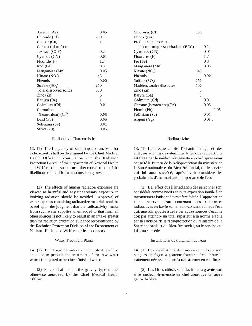
7
Arsenic (As) 0.05Chloride (Cl) 250Copper (Cu) 1Carbon chloroformextract (CCE) 0.2
Cyanide (CN) 0.01Fluoride (F) 1.7Iron (Fe) 0.3Manganese (Mn) 0.05Nitrate (NO3) 45Phenols 0.001Sulfate (SO4) 250Total dissolved solids 500Zinc (Zn) 5Barium (Ba) 1Cadmium (Cd) 0.01Chromium(hexovalent) (Cr6) 0.05
Lead (Pb) 0.05Selenium (Se) 0.01Silver (Ag) 0.05.
Chlorures (Cl) 250Cuivre (Cu) 1Produit d'une extraction
chloroformique sur charbon (ECC) 0,2Cyanures (CN) 0,01Fluorures (F) 1,7Fer (Fe) 0,3Manganèse (Mn) 0,05Nitrate (NO3) 45Phénols 0,001Sulfate (SO4) 250Matières totales dissoutes 500Zinc (Zn) 5Barym (Ba) 1Cadmium (Cd) 0,01Chrome (hexavalent)(Cr6) 0,05Plomb (Pb) 0,05Sélénium (Se) 0,01Argent (Ag) 0,05 .
Radioactive Characteristics Radioactivité
13. (1) The frequency of sampling and analysis forradioactivity shall be determined by the Chief MedicalHealth Officer in consultation with the RadiationProtection Bureau of the Department of National Healthand Welfare, or its successors, after consideration of thelikelihood of significant amounts being present.
13. (1) La fréquence de l'échantillonnage et desanalyses aux fins de déterminer le taux de radioactivitéest fixée par le médecin-hygéniste en chef après avoirconsulté le Bureau de la radioprotection du ministère dela Santé nationale et du Bien-être social, ou le servicequi lui aura succédé, après avoir considéré lesprobabilités d'une irradiation importante de l'eau.
(2) The effects of human radiation exposure areviewed as harmful and any unnecessary exposure toionizing radiation should be avoided. Approval ofwater supplies containing radioactive materials shall bebased upon the judgment that the radioactivity intakefrom such water supplies when added to that from allother sources is not likely to result in an intake greaterthan the radiation protection guidance recommended bythe Radiation Protection Division of the Department ofNational Health and Welfare, or its successors.
(2) Les effets dus à l'irradiation des personnes sontconsidérés comme nocifs et toute exposition inutile à unrayonnement ionisant devrait être évitée. L'approbationd'une réserve d'eau contenant des substancesradioactives est basée sur la radio-concentration de l'eauqui, une fois ajoutée à celle des autres sources d'eau, nedoit pas atteindre un total supérieur à la norme établiepar la Division de la radioprotection du ministère de laSanté nationale et du Bien-être social, ou le service quilui aura succédé.
Water Treatment Plants Installations de traitement de l'eau
14. (1) The design of water treatment plants shall beadequate to provide the treatment of the raw waterwhich is required to produce finished water.
14. (1) Les installations de traitement de l'eau sontconçues de façon à pouvoir fournir à l'eau brute letraitement nécessaire pour la transformer en eau finie.
(2) Filters shall be of the gravity type unlessotherwise approved by the Chief Medical HealthOfficer.
(2) Les filtres utilisés sont des filtres à gravité saufsi le médecin-hygiéniste en chef approuve un autregenre de filtre.
8
(3) Heating facilities of a safe type should beprovided in buildings which will be occupied bypersonnel, and should be adequate for comfort, as wellas for protection of the equipment.
(3) Dans les bâtiments abritant du personnel, desinstallations de chauffage sécuritaires devraient êtrefournies afin d'assurer le confort des occupants et laprotection de l'équipement.
(4) The buildings shall be well-ventilated bymeans of windows and doors, roof ventilators or othermeans. All rooms, compartments, pits and otherenclosures below the grade floor, which must be enteredand in which an unsafe atmosphere may develop, orwhere excessive heat may be built up by equipment,shall have adequate forced ventilation. The equipmentshould be capable of producing at least six completeturnovers of air an hour. Rooms containing equipmentor piping should be adequately heated, ventilated and, ifnecessary, dehumidified to prevent injuriouscondensation. Where practicable, ventilation should besupplemented by insulation of the building, equipmentand piping. Switches which control the forcedventilation shall be located in order to be convenientlymanipulated from outside such compartments.
(4) Les bâtiments sont largement ventilés aumoyen de fenêtres, de portes, de ventilateurs de toit ouautrement. Les locaux, compartiments, fosses et autresenceintes accessibles situés sous le niveau du rez-de-chaussée et où une atmosphère malsaine peut se formerou encore où une quantité excessive de chaleur produitepar l'équipement peut s'accumuler doivent être desservispar un système adéquat de ventilation par air pulsé.L'équipement devrait pouvoir effectuer au moins sixrenouvellements d'air complets par heure. Les locauxabritant de l'équipement ou de la tuyauterie devraientêtre chauffés, aérés et, au besoin, déshumidifiés pourempêcher la condensation nuisible. Si possible, laventilation devrait être complétée par l'isolation dubâtiment, de l'équipement et de la tuyauterie. Lesinterrupteurs de commande du système de ventilationpar air pulsé sont placés de manière àpouvoir êtrefacilement manœuvrés depuis l'extérieur descompartiments desservis.
(5) Buildings shall be adequately lightedthroughout by means of natural light or by artificiallighting facilities, or both. Control switches, whereneeded, shall be conveniently placed at the entrance toeach room or compartment. All electric wiring andequipment shall be of a type listed by the CanadianStandards Association Testing Laboratories andinstalled in accordance with the CSA Standard C22.1 -1986 Canadian Electrical Code - Part I -Safety Standardfor Electrical Installationand those of the Governmentof the Northwest Territories and local governmentauthorities.
(5) Les bâtiments sont adéquatement etcomplètement éclairés au moyen d'un éclairage naturel,d'installations d'éclairage artificiel, ou des deux. Lesinterrupteurs de commande nécessaires sont placés à unendroit pratique, à l'entrée de chaque local oucompartiment. Le câblage et l'équipement électriquesdoivent être d'un genre approuvé par les laboratoiresd'essai de l'Association canadienne de normalisation etinstallés en conformité avec la norme de l'ACNORnuméro C22.1, Code canadien de l'électricité 1986,partie I, Norme de sécurité relative aux installationsélectriqueset les normes fixées par le gouvernement desTerritoires du Nord-Ouest ou les administrationslocales.
(6) Where lavatory and toilet facilities areprovided at the water treatment plant, wastes shall besafely disposed of, without danger of contaminating thewater and preferably they shall be discharged directlyinto an approved sewer.
(6) Lorsque des installations sanitaires sontaménagées dans une station de traitement de l'eau, leseaux usées sont évacuées d'une manière ne présentantaucun danger de contamination de l'eau et, depréférence, elles sont évacuées directement dans unégout approuvé.
Chlorination Chloration
15. (1) Drinking water shall be chlorinated or receiveother bactericidal treatment as approved by the ChiefMedical Health Officer in all cases when the supply isobtained from a surface source, and in the case of a
15. (1) Lorsque l'approvisionnement provient d'unesource d'eaux de surface, l'eau potable est chlorée ouautrement traitée avec des substances bactéricides suiteà l'approbation du médecin-hygiéniste en chef. Dans le
9
groundwater source if the water may be subject tocontamination in the well or in storage reservoirs ormains. Additional chlorination may be required if thereis reasonable possibility for contamination subsequentto the original disinfection.
cas d'une source d'eau souterraine, ces traitements sontrequis si l'eau est susceptible d'être contaminée dans lespuits, les réservoirs de retenue ou dans les conduitesd'amenée. S'il existe une possibilité raisonnable quel'eau soit contaminée après une première désinfection, ilpeut être nécessaire de procéder à une secondechloration.
(2) Chlorination equipment shall have a maximumfeed capacity at least 50% greater than the highestdosage required to provide a free chlorine residual.
(2) L'équipement de chloration a une capacitémaximale d'alimentation au moins 50 % supérieure à ladose maximale requise pour obtenir un résidu de chlorelibre.
(3) Dependable feed equipment, either of the gasfeed or positive displacement solution feed type, shallbe used for adding chlorine. Automatic proportioningof the chlorine dosage to the rate of flow of the watertreated shall be provided at all treatment plants wherethe rate of flow varies without manual adjustment ofpumping rates. In the selection and design ofequipment, care should be taken to ensure that there issufficient dilution of chlorine in the water wheneverthere is contact with piping, valves or fittings which arecorrodible.
(3) Des appareils fiables, soit du type àalimentation du chlore à l'état gazeux ou du type àalimentation du chlore en solution à l'aide de pompesvolumétriques, sont utilisés pour l'ajout du chlore. Dansle cas des installations de traitement dont le débit d'eauvarie sans que le taux de pompage ne puisse être réglémanuellement, des appareils permettant le dosageautomatique proportionnel au débit d'eau sont utilisés.Lorsque l'eau chlorée doit entrer en contact avec destuyaux, des soupapes ou des raccords susceptibles de secorroder, les appareils choisis ou conçus devraientpermettre une dilution suffisante du chlore dans l'eau.
(4) All chlorination equipment should be installedin duplicate, in order to provide standby units forensuring uninterrupted operation. In addition, spareparts consisting of at least the commonly expendableparts such as glassware, rubber fittings, hose clamps,and gaskets should be provided for effecting emergencyrepairs. In some cases, satisfactory emergencychlorinators may consist of discontinued equipment if itis operable and adequately sized.
(4) Tout équipement de chloration devrait êtreinstallé en double de façon à ce que des installations desecours puissent assurer un fonctionnementininterrompu. De plus, des pièces de rechangepour lespièces généralement non réutilisables tels la verrerie, lesraccords en caoutchouc, les colliers de serrage et lesjoints d'étanchéité statiques devraient être prévues pourles réparations d'urgence. Dans certains cas, deschlorateurs désuets, mais en bon état et de tailleappropriée peuvent être utilisés comme appareils desecours.
(5) Where gas feed chlorinators are employed, ascale shall be provided for weighing the chlorinecylinders serving each operating chlorinator.Preferably, weigh scales for 68 kg cylinders should berecessed in the floor, and the recess provided with adrain.
(5) Lorsque des chloronomes sont utilisés, unebalance permet de peser les bouteilles de chlore reliéesà chaque chloronome. Les balances pour bouteilles de68 kg sont de préférence encastrées dans le plancher etles cavités sont munies d'un tuyau d'écoulement.
(6) Where a powdered hypochlorite is used,solutions should be prepared in a separate tank. Theclear liquid should be siphoned to the solution storagetank from which it is drawn by the hypochlorinator. Asecond tank is not required when chlorine is supplied asa solution.
(6) Lorsque de l'hypochlorite en poudre est utilisé,la solution devrait être préparée dans un réservoirdistinct. La solution devrait être siphonnée à unréservoir de stockage et ensuite aspirée par le chlorateur.Un second réservoir n'est pas requis lorsque le chlore estfourni sous forme de solution.
(7) Where gas chlorine is used, there shall be a (7) Lorsque du chlore à l'état gazeaux est utilisé,
10
canister-type respirator with a full face mask in alocation handy to the operator. The canister shall bespecifically designed to protect against chlorine and anew one should be obtainedeach time one is used.
un respirateur à boîte filtrante muni d'un masquecomplet est placé à la portée de l'opérateur. La boîtefiltrante est spécialement conçuepour assurer uneprotection contre le chlore et devrait être remplacéeaprès chaque utilisation.
(8) Safety chains should be used to retain 68 kgcylinders of chlorine gas, either in storage or on weighscales, in a safe upright position.
(8) Des chaînes de sécurité devraient être utiliséespour retenir les bouteilles de chlore de 68 kg en positionverticale, tant en entrepôt que sur les balances.
(9) Gas chlorine equipment, includingchlorinators, weigh scales and chlorine cylinders, shallbe located in an isolated building, room or rooms. Inlarger installations, the storage and scale facilitiesshould be in a room separated from the chlorinators.The construction of the room or rooms should be of fireresistant material and have concrete floors.
(9) L'équipement de chloration au chlore gazeux,y compris les chloronomes, les balances et les bouteillesde chlore, est situé dans un bâtiment isolé ou dans un ouplusieurs locaux détachés, de préférence construits enmatériaux qui résistent au feu et dotés d'un plancher enbéton. Dans les installations plus importantes, l'entrepôtet les balances devraient se situer dans un local séparédes chloronomes.
(10)Areas containing chlorine or chlorinatorequipment shall be clearly marked "DANGER!CHLORINE STORAGE" or "DANGER! CHLORINEFEED EQUIPMENT" as applicable.
(10)Dans les aires renfermant du chlore ou del'équipement de chloration, sont visiblement affichés lesmessages suivants :*DANGER! ENTREPOSAGE DECHLORE+ ou *DANGER! ÉQUIPEMENT DECHLORATION+.
(11)There should be two or more exits if thedistance of travel to the nearest exit exceeds 4.5 m.
(11) Il devrait y avoir deux sorties ou plus afin quela distance à franchir pour se rendre jusqu'à la sortie laplus rapprochée ne soit jamais supérieur à 4,5 m.
(12)There should be continuous mechanicalventilation at the rate of three air changes anhour.Alternatively there should be screened openings to theoutdoors with a size of 0.02% of the floor area
(a) within 150 mm of the floor, and(b) near the ceiling.
(12) Il devrait y avoir un système de ventilationmécanique assurant trois renouvellements d'air parheure. À défaut d'une telle installation, il devrait y avoirdes ouvertures grillagéesdonnant à l'extérieur, d'unesuperficie correspondant à 0,02 % de celle du plancher,et situées aux endroits suivants :
a) à au plus 150 mm du plancher;b) près du plafond.
(13) In addition, there should be emergencymechanical ventilation sufficient to produce 30 airchanges an hour taking suction at floor level. Theswitch for the emergency fan should be located outsidethe chlorinator room. It should be posted with a signwarning that 10 minutes should elapse after starting thefan before entering the room.
(13) Il devrait également y avoir un système deventilation mécanique de secours, à aspiration au niveaudu plancher, capable d'assurer 30 renouvellements d'airpar heure. L'interrupteur de commande du ventilateur desecours devrait être situé à l'extérieur du local deschlorateurs et être surmonté d'un avis indiquantd'attendre 10 minutes après la mise en marche duventilateur avant d'entrer dans le local.
(14)The temperature in the storage and scale roomshould never be higher and preferably slightly lowerthan that in the chlorinator room. The gas lines betweenthe scales, chlorinators and injectors should not belocated on an outside wall or in a location where lowtemperatures may be encountered.
(14)La température dans la salle d'entreposage etdes balances ne devrait jamais être supérieure à celle quiprévaut dans la salle des chlorinateurs; elle devrait, depréférence, être légèrement inférieure à cette dernière.Les conduites de gaz entre les balances, les chlorinateurset les injecteurs ne devraient pas être acheminées le long
11
d'un mur extérieur ou à un endroit où règne une bassetempérature.
16. (1) The application of chlorine shall be sufficientto provide 0.2 mg/l of residual free chlorine after athorough mixing of the chlorine and water and 20minutes of contact time after the mixing.Notwithstanding the foregoing, the Chief MedicalHealth Officer may decide on another chlorine residualfor particular local circumstances.
16. (1) La quantité de chlore à ajouter dans l'eau doitêtre suffisante pour que la concentration de résidu dechlore libre, après un parfait mélange du chlore et del'eau et un temps de contact de 20 minutes suivant cemélange, soit de 0,2 mg/l. Malgré ce qui précède, lemédecin-hygiéniste en chef peut modifier cette exigenceen cas de circonstances locales particulières.
(2) The chlorine residual test is performed on asample of the plant or pipeline effluent, after it has beenheld for 20 minutes, unless it is certain that there hasalready been a chlorine contact time of 20 minutes.
(2) La détermination du taux de chlore résiduel esteffectuée sur un échantillon d'un effluent de la station detraitement ou d'une canalisation après une périoded'attente de 20 minutes, à moins qu'il ne soit établi qu'ily ait déjà eu un temps de contact de 20 minutes.
(3) Where bacterial counts in the distributionsystem are high, the minimum requirements for chlorineresidual should be increased.
(3) Lorsque la numération bactérienne dans leréseau de distribution est élevée, la concentration dechlore résiduel minimale devrait être augmentée.
(4) Where possible, a chlorine residual should bemaintained in all active parts of the distribution system.
(4) Si possible, une certaine concentration dechlore résiduel devrait être maintenue dans toutes lesparties actives du réseau de distribution.
(5) There shall be a minimum total chlorinecontact period of 20 minutes in the pipeline andreservoirs, before the first consumption by any personof the treated water.
(5) Il doit y avoir un temps de contact total dechlore de 20 minutes dans les canalisations et lesréservoirs avant que toute personne puisse consommerl'eau traitée.
(6) There shall be a permanent standard chlorineresidual comparator test kit at each water plant wherechlorination is undertaken.
(6) Toute station de traitement de d'eau quieffectue la chloration est dotée en permanence d'unetrousse standard du type comparateur pour effectuer lesdosages de chlore résiduel.
(7) Whenever it is necessary to pumpunchlorinated water which might not be potable into thedistribution system the Chief Medical Health Officer orin his or her absence a responsible Health Officer, shallbe notified immediately. After the emergency, the watermains and service lines shall be disinfected as stated insection 22.
(7) Lorsqu'il est nécessaire d'acheminer dans unréseau de distribution de l'eau non chlorée etpossiblement non potable, le médecin-hygiéniste en chefou, en son absence, un agent de la santé compétent, enest immédiatement avisé. Une fois l'urgence satisfaite,les conduites principales et les conduites debranchement sont désinfectées de la manière prévue àl'article 22.
Fluoridation Fluoruration
17. (1) Fluoridation is recommended for communitywater supplies. Before the equipment is ordered, thefluorides concentration in the raw water shall bechecked to be sure of the need for fluorides.
17. (1) Il est recommandé de procéder à la fluorurationdes réserves d'eau d'une collectivité. Avant decommander l'équipement, une vérification de laconcentration de fluorures dans l'eau est effectuée pours'assurer de la nécessité de la fluoruration.
12
(2) The fluorides feed rate shall be proportioned tothe water flow rate. Where a pump supplies water atapproximately a constant rate, a suitable fluoridator isatype which operates simultaneously with the pump. Thepumping variation should be less than 10% from themean.
(2) Le taux d'alimentation en fluorures estproportionnel au débit d'eau. Lorsque le débit d'eaufourni par la pompe est à peu près constant, le fluorateuridéal est celui qui agit selon le fonctionnement de lapompe. Le débit d'eau fourni par la pompe ne devraitpas s'écarter de plus de 10 % de la moyenne.
(3) The sampling point should be a tap located ona line before the point where interfering substances(alum, chlorine, polyphosphates and other suchsubstances) are added. The application point for thefluorides should be far enough ahead of this to ensurethorough mixing. Usually a distance equivalent to 10pipe diameters would be sufficient for this purpose.
(3) Le point d'échantillonnage devrait se trouver enamont de l'endroit où sont ajoutées certaines substances(alum, chlore, phosphates et autres substances du genre)venant modifier la composition de l'eau. Le pointd'introduction des fluorures dans le réseau devrait êtreencore plus en amont pour que les fluorures puissentêtre parfaitement dispersés dans l'eau. À cette fin, unedistance équivalant à 10 diamètres de conduite esthabituellement suffisante.
(4) If such an arrangement is not practical in viewof the existing plant layout, thenaccurate tests may bemade following neutralization in the case of chlorineand removal by distillation in the case of aluminum(from alum) and phosphates. The operator should makeappropriate adjustments in the readings of his or hertests.
(4) Si un tel aménagement n'est pas pratique enraison de la disposition actuelle des lieux, des essaisprécis peuvent être menés après neutralisation du chloreet enlèvement par distillation de l'alum et desphosphates. Les ajustements nécessaires devraient alorsêtre apportés à la lumière des résultats de tels essais.
(5) The concentration of fluorides in the finishedwater shall be within the range of 1.2 and 1.6 mg/l. Theoptimum proportion is 1.4 mg/l.
(5) La concentration de fluorures dans l'eau finiese situe entre 1,2 et 1,6 mg/l, la concentration optimaleétant de 1,4 mg/l.
(6) The following control procedures are requiredand all results should be recorded:
(a) the operator should make daily tests todetermine the fluorides concentration inthe treated water. In some installationsthere will be instantaneous variations inthe fluorides concentration at the samplingtap due to the briefly intermittentdischarge characteristics of some fluoridesfeeders. To compensate for thesevariations a large bottle of water should bedrawn as the source of samples for testing;
(b) on a weekly basis duplicate samples of thewater to be tested should be submitted toalaboratory designated by the ChiefMedical Health Officer. The laboratoryanalyses will establish the accuracy of theplant operator's field tests and his or herability to properly control the treatment.When this criteria has been attained,duplicate samples should be submitted ona monthly basis only;
(c) as a daily routine, the chemical dosageshould be calculated based on the
(6) Les mécanismes de contrôle ci-après décritssont obligatoires et les résultats devraient être consignésdans un registre :
a) des essais quotidiens sont faits pourdéterminer la concentration de fluoruresdans l'eau traitée. Dans certainesinstallations, des variations instantanéesdans la concentration de fluorures peuventêtre décelées à la prise d'échantillon, enraison des brèves interruptions de débitdes fluorateurs à fonctionnementintermittent. Pour éviter que les résultatsde l'essai ne soient faussés, une grossebouteille d'eau devrait être prélevéecomme échantillon;
b) chaque semaine, un double de chaqueéchantillon d'eau prélevé aux finsd'analyses devrait être soumis à unlaboratoire désigné par le médecin-hygiéniste en chef pour que puissent êtrevérifiées la précision des essais faits à lastation et l'aptitude de l'exploitant àcontrôler adéquatement le traitement del'eau. Une fois cette précision et cette
13
consumption of fluorides and volume ofwater treated.
aptitude établies, le double deséchantillons ne devrait être soumis qu'unefois par mois;
c) tous les jours, le dosage de fluorures estcalculé sur la base de la quantité defluorures utilisée par rapport au volumed'eau traitée.
(7) Protection to the skin and lungs of the operatorhandling the fluoride chemical shall be maintained asfollows:
(a) if the equipment is not of a type whichprevents the dust entering the air when thefluorides chemical is being replaced, thenthe equipment should be in a separateroom with suitable exhaust venting fromthe floor level to the outside atmosphere.A vacuum cleaner in which disposablebags are used would be a suitablealternative, and it could also be used incleaning the room. The bags should beeither buried at the nuisance grounds orwashed out in the sewer;
(b) respirator, cloth cap, rubber gloves, rubberapron and goggles should be used at alltimes when handling the dry chemical, andthese should be stored outside thefluoridation room;
(c) the operator should not smoke whilehandling the dry powder;
(d) instructions should be posted instructingthe staff to observe the points contained inthis section.
(7) La protection de la peau et des poumons de lapersonne qui manipule les fluorures est assurée par lerespect des directives suivantes :
a) si l'équipement ne permet pas d'empêcherla dispersion des particules chimiques dansl'air au moment de la remise en place desfluorures, l'équipement devrait être installédans une salle distincte desservie par unventilateur d'extraction convenable,aspirant l'air au niveau du sol et l'évacuantà l'extérieur. Une bonne solution derechange serait un aspirateur avec sacsjetables, lequel pourrait également êtreutilisé pour l'entretien de la salle. Les sacsusés devraient être enfouis à un endroitprévu à cette fin ou leur contenu chassédans l'égout;
b) lors de la manipulation de la poudrechimique, le respirateur, la casquette detoile, les gants, le tablier de caoutchoucainsi que les lunettes de sécurité devraientêtre utilisés en tout temps et devraient êtreentreposés à l'extérieur de la salle defluoration;
c) la personne qui manipule la poudre sèchene devrait pas fumer;
d) des directives portant sur les points traitésau présent article devraient être affichées.
PART III PARTIE III
PUMPING STATIONS, RESERVOIRSAND DISTRIBUTION SYSTEMS
STATIONS DE POMPAGE, RÉSERVOIRSET RÉSEAUX DE DISTRIBUTION
Pumping Stations Stations de pompage
18. (1) The design of pumping stations shall be basedon the provision to ensure maintenance of the sanitaryquality of the water pumped through it, and to facilitatecleanliness, continuity and ease of operation.Subsurface pits, subterranean piping and connectionsand inaccessible installations should be avoided.
18. (1) Les stations de pompage sont conçues demanière à préserver la qualité de l'eau qui y est pompéeet à favoriser l'entretient ainsi que la simplicité et lacontinuité de son fonctionnement. Elle devraitcomporter le moins possible de fosses et decanalisations souterraines ainsi que d'installationsinaccessibles.
(2) The location should be chosen so that there will (2) L'emplacement devrait être choisi en fonction
14
be adequate control over every external factor (such asusage of surrounding areas) which might contribute tothe impairment of the sanitary quality of the water.
de la possibilité de contrôler convenablement lesfacteurs externes (telle l'utilisation faite des secteursattenants) pouvant contribuer à la dégradation de laqualité de l'eau.
(3) The wet wells and pump reservoirs which arepart of pumping stations shall conform with section 19.
(3) Les bâches d'aspiration et les réservoirs quifont partie intégrante des stations de pompage sontconformes à l'article 19.
Equalizing Reservoirs, Elevated Tanks,Standpipes and Pressure Tanks for Finished Water
Réservoirs d'équilibre, châteaux d'eau,réservoirs au sol et réservoirs sous pression
pour l'eau finie
19. (1) The most up-to-date standards should befollowed where applicable in the design of reservoirsand other tanks.
19. (1) Les normes applicables les plus récentes sontrespectées dans la conception des réservoirs et desciternes.
(2) The locations, size and type of reservoir, tankor standpipe should be integrated with the distributionsystem, ground elevations and effective pressures, typeand capacity of supply, economics of pumping andconstruction, consumer use and terrain. The design tobe desired should give uniform pressures during the daywith no pressure drop below 140 kPa.
(2) L'emplacement, la dimension et la sorte deréservoir, de citerne ou de réservoir au sol devraient êtredéterminés en fonction de l'utilisation de l'eau, du réseaude distribution, des accidents de terrain, de la contrainteeffective, du type et de la capacité de la réserve d'eau, dela rentabilité d'une installation de pompage et saconstruction ainsi que du genre de terrain. Lesréservoirs devraient être conçus pour permettre demaintenir des pressions constantes durant la journée,sans chutes sous les 140 kPa.
(3) Reservoirs shall have watertight covers orroofs which exclude birds, animals, insects andexcessive dust.
(3) Les réservoirs doivent être munis d'uncouvercle ou d'un toit étanche qui empêche les oiseaux,les animaux, les insectes et la poussière de pénétrer àl'intérieur.
(4) There shall be locks on access manholes,fencing and other precautions in order to preventtrespassing, vandalism or sabotage.
(4) Des serrures sont installées sur les trousd'homme d'accès, ainsi que sur les clôtures et d'autresmesures sont prises pour décourager les intrusions, ainsique les actes de vandalisme et de sabotage.
(5) Steps should be taken to prevent an excessivebuild-up of ice which would damage the reservoir.
(5) Des mesures devraient être prises pourempêcher l'accumulation excessive de glacepouvantendommager les réservoirs.
(6) There shall be consideration of public healthsafety in the location of ground level reservoirs. Thebottom should be above the groundwater table andpreferably above any possible flooding.
(6) L'emplacement des réservoirs au niveau du solest déterminé en tenant compte de la santé et de lasécurité du public. Le fond des réservoirs devrait sesituer au-dessus de la nappe phréatique et, depréférence, au dessus de tout niveau possible de crue.
(7) Where the bottom of a reservoir is below thenormal ground surface, separation from possiblesources of contamination shall be provided as follows:
(a) 46 m from any septic tank, sewage liftstation, sewage disposal point, sewage
(7) Les réservoirs dont le fond se trouve au-dessusdu niveau normal du sol doivent être installés à unecertaine distance de toute source de contaminationpossible, à savoir, selon le cas :
a) à une distance de 46 m d'une fosse
15
disposal field or other similar source ofcontamination;
(b) 8 m from any sewer pipe and preferably30 m;
(c) for all other sources of contamination asfar as appears to be reasonable in view oflocal conditions and the type ofconstruction.
septique, d'une station de relevage deseaux usées, d'un point de rejet des eauxusées, d'un champ d'épuration ou de touteautre source de contamination similaire;
b) à une distance de 8 m et de préférence30 m de toute conduite d'égout;
c) à une distance raisonnable de toute autresource de contamination, compte tenu desconditions locales et du type deconstruction.
(8) Tops of ground level reservoirs shall be notless than 600 mm above the normal ground surface, andshall be a minimum of 1.2 m above any possible floodlevel.
(8) Le dessus des réservoirs au niveau du sol estsitué à au moins 600 mm au-dessus du niveau normaldu sol et à au moins 1,2 m au-dessus de tout niveau decrue possible.
(9) The area surrounding ground level reservoirsshall be graded to prevent surface water from standingagainst the structure.
(9) Autour des réservoirs au niveau du sol, leterrain est régalé en pente pour empêcher que les eauxde surface ne stagnent contre les réservoirs.
(10)There shall be footing drains around thereservoir, which should be drained by gravity ifpossible. There should be a means of observing thevolume of flow from the footing drains.
(10)Des drains de semelle, si possible à écoulementpar gravité, sont posés autour des réservoirs. Undispositif devrait être prévu pour observer le débit d'eaudans les drains.
(11)The maximum variation of working levels instorage reservoirs which float on a distribution systemshould not exceed 9 m.
(11)La variation maximale du niveau utile desréservoirs de stockage incorporés à un réseau dedistribution ne devrait pas être supérieure à 9 m.
(12)Water level controls or telemetering equipmentshould be provided in reservoirs on the distributionsystem where there is an appreciable variation in level.
(12)Lorsque la variation du niveau est importante,les réservoirs devraient être munis de régulateurs deniveau d'eau ou d'équipement de télémesure.
(13)Water level control switches or telemeteringequipment should be provided, with warning or alarmsin appropriate places about the community, so that highand low water levels may be immediately reported.
(13)Des interrupteurs reliés aux régulateurs deniveau ou d'équipement de télémesure sont prévus, avecavertisseurs ou signaux d'alarme placés à des endroitsstratégiques de la collectivité, afin que les niveaux d'eautrop hauts ou trop bas soient signalés immédiatement.
(14)Overflows on structures shall have free falldischarges that are in plain view, and should bedesigned so that they will not freeze.
(14)Les déversoirs des réservoirs sont du type àdéversement libre et sont à l'épreuve du gel.
(15)A manhole on a reservoir or tank shall beframed so that there is a raised lip around the edge. Thelip shall be at least 100 mm high, and preferably 150mm, and the join between the lip and the roof shall bewatertight. It shall be fitted with a watertight coverwhich overlaps the lip of the manhole and extends downaround the frame at least 50 mm. The cover shall behinged at one side and shall be provided with a lockingdevice.
(15)Le contour des trous d'homme sur lesréservoirs ou les citernes est muni d'un collet. Le colletmesure 100 mm et de préférence 150 mm de haut, et lejoint entre le collet et le toit est étanche. Un couvercleétanche recouvre complètement le collet et est muni d'unrebord d'au moins 50 mm qui tombe sur les parois duréservoir.
16
(16)The roof of the structure should be welldrained. The downspout pipes of the roof drain shallnot enter the reservoir or connect to the overflow fromthe reservoir. There shall be no parapets or constructionwhich will tend to pool the water or snow on the roof.
(16)Le toit des réservoirs devrait être muni deséléments nécessaires à l'écoulement des eaux de pluie.Les tuyaux de descente reliés à l'avaloir ne sont pasacheminés à l'intérieur des réservoirs ni raccordés audéversoir. Le toit ne doit pas être muni de parapets oud'autres constructions pouvant causer l'accumulation del'eau ou de la neige.
(17)Valve stems or similar projections through theroof shall be designed with a wall sleeve, elevated atleast 100 mm above the roof top, set in a curbedopening, or welded to the cover plate. The openingmust be covered by an overlapping, turned-down hood,welded to the valve stem.
(17)Les tiges de soupape ou les autre élémentsfaisant sailli sur le toit des réservoirs sont protégés parun manchon s'élevant à une hauteur d'au moins 100 mmau-dessus du toit. Les manchons sont soudés aucouvercle ou passent par une ouverture à collet. Lesouvertures sont recouvertes d'un capuchon rabattu quichevauche la tige en saillie et qui est soudé à celle-ci.
(18)Vents, overflows, finial decorations andwarning lights shall be so constructed as to excludedust, birds, animals and insects. There shall be no directconnection between an overflow and any drain orsewer. A ground level vent must terminate in aninverted U construction, the opening of which is at least600 mm above the ground surface.
(18)Les évents, les déversoirs, les élémentsdécoratifs et les feux avertisseurs sont construits demanière à empêcher l'introduction de la poussière, desoiseaux, des animaux et des insectes. Les déversoirs nesont pas directement raccordés aux drains ou auxcanalisations d'égout. Tout évent situé près du sol doitse terminer en forme de U renversé, l'ouverture placéeà une hauteur d'au moins 600 mm au-dessus du niveaudu sol.
(19)Unsafe water shall not be stored adjacent to afinished water compartment when only a single wallseparates the two.
(19)L'eau de mauvaise qualité ne doit pas êtrestockée dans un compartiment voisin d'un compartimentd'eau finie lorsqu'une seule paroi sépare les deuxcompartiments.
(20)Reservoirs should be drainable to the groundsurface in such a manner as to preclude contaminationby surface water and access by animals. There shall beno direct connection to a sewer or storm. Alternatively,a reservoir should be drained by pumping from a sumpat a lower level than the bottom. A manhole should belocated directly above the sump, to permit servicing ofthe pump intake and to allow dewatering with a portablepump.
(20)Le contenu des réservoirs devraient être évacuéà la surface du sol sans qu'il y ait risque d'intrusiond'animaux ou risque de contamination par des eaux desurface. Les réservoirs ne sont pas directementraccordés à un égout sanitaire ou pluvial. À défaut, ilsdevraient être vidés au moyen d'une pompe installéedans un puisard situé à un niveau inférieur à celui dufond du réservoir. Le puisard devrait être muni d'un troud'homme pour permettre l'entretien de la prise etl'assèchement du puissard au moyen d'une pompeportative.
(21) Interior surfaces of all steel reservoirs shall beprotected by paints or other protective coatings orcathodic protection according to practices recommendedby the American Water Works Association or theCanadian Standards Association.
(21)Les parois intérieures des réservoirs en aciersont protégées par une peinture ou d'autres revêtementsde protection ou encore une protection cathodique enconformité avec les pratiques recommandées parl'American Water Works Association ou l'Associationcanadienne de normalisation.
(22)There should be periodical disinfection in orderto ensure a continued source of finished water.
(22)Afin que l'alimentation en eau finie soitcontinue, les réservoirs devraient être désinfectéspériodiquement.
17
Water Mains Conduites d'eau principales
20. (1) Pipes and pipe packing and jointing materialsshall have been manufactured in conformity with thelatest standard specifications issued by the AmericanWater Works Association or the Canadian StandardsAssociation. Plastic pipe shall be approved by and bearthe seal of the Canadian Standards Association.Selection of the pipe material and design shall be madeafter giving consideration to the possible deleteriousaction of the soils and water which will be surroundingthe pipe, the water to be distributed and possibleelectrolytic action on the metal parts.
20. (1) Les tuyaux ainsi que les matériaux dejointement et d'obturation utilisés doivent être fabriquésen conformité avec les normes récentes prescrites parl'American Water Works Association ou l'Associationcanadienne de normalisation. Les tuyaux en plastiquesont approuvés par l'Association canadienne denormalisation et en portent l'étiquette. La conception etles matériaux de fabrication des tuyaux sont choisis entenant compte de l'effet possiblement nuisible du sol etde l'eau qui entoureront le tuyau, de l'eau qui estdistribuée et de la possibilité d'une réactionélectrolytique avec les pièces métalliques.
(2) Les conduites d'eau principales devraient êtreprotégées contre le gel.
(3) The minimum working pressure during theflow in outlying parts of the distribution system shouldbe 140 kPa.
(3) La pression de service minimale dans lesparties périphériques du réseau de distribution devraitêtre de 140 kPa.
(4) If water hydrants are installed, the supply ofwater shall be adequate to provide water for the firepumps and regular use, and at the same time maintainadequate positive pressure in all parts of the system.
(4) Si le réseau de distribution comporte des prisesd'eau, la réserve d'eau est suffisante pour répondre à lademande régulière et à une demande ponctuelle en eaud'incendie, et pour maintenir une pression positiveadéquate dans toutes les parties du réseau.
(5) The dead-end of a main should have a firehydrant or blow-off connected for flushing purposes.No flushing device shall be connected directly to anysewer.
(5) L'impasse d'une conduite principale devrait êtreraccordée à un poteau d'incendie ou à un robinetd'évacuation aux fins de rinçage. Aucun dispositif derinçage n'est raccordé directement à un égout.
(6) Water mains shall be laid a minimum of 3 mfrom sewers which run in the same direction. Where itis clearly very difficult to comply with this regulation,then
(a) the bottom of the water main shall be atleast 450 mm higher than the top of thesewer, and
(b) the water main shall rest on undisturbedsoil.
(6) Les conduites d'eau principales sont installéesà une distance d'au moins 3 m de toute canalisationd'égout parrallèle. S'il est trop difficile de se conformerà cette règle, les règles suivantes s'appliquent :
a) la partie inférieure d'une conduite d'eauprincipale doit se situer à au moins450 mm de la partie supérieure d'unecanalisation d'égout située au-dessous;
b) la conduite d'eau principale repose sur unsol non remanié.
18
(7) When a water main must cross a sewer, thebottom of the water main shall be laid at least 450 mmabove the top of the sewer. The vertical separation shallbe maintained for that portion of the water main locatedwithin 3 m of the sewer, the 3 m to be measured as thenormal distance from the water main to the sewer.
(7) Lorsqu'une conduite d'eau principale croise unecanalisation d'égout, la partie inférieure de la conduited'eau doit se situer à au moins 450 mm de la partiesupérieure de la canalisation d'égout qui se situe au-dessous. Cette distance s'applique pour toute partie de laconduite d'eau comprise dans un rayon de 3 m de lacanalisation d'égout, cette distance de 3 m étant ladistance normale entre la conduite d'eau et lacanalisation d'égout.
(8) When it is impossible to achieve the conditionas stated in subsections (6) and (7) then both the watermain and the sewer shall be constructed of Class 150pressure-type pipes. There shall be adequate support oneach side of the crossing for both pipes so that there willbe no stresses in either pipe caused by one pipe settlingon the other. Pipe sections shall be centred at thecrossing so that there is a maximum distance from thecrossing to all joints. Both pipes shall be pressure testedto assure that there are no leaks.
(8) S'il est impossible de respecter les dispositionsdes paragraphes (6) et (7), alors la conduite d'eauprincipale et la canalisation d'égout sont fabriquées detuyaux sous pression de catégorie 150. Chacune desdeux canalisations est soutenue de part et d'autre ducroisement afin qu'aucune des deux n'exerce unepression sur l'autre. Les sections des tuyaux sontcentrées de manière à ce que les joints de chacune descanalisations se situent à égale distance de part et d'autredu point d'intersection entre les deux canalisations.L'étanchéité des canalisations est vérifiée au moyen d'unessai sous pression.
(9) Where water and sewer pipes are contained ina utilidor, there shall be adequate provision for drainagein order to prevent contamination of the water supplyduring repairs and breakdowns.
(9) Lorsque des canalisations d'eau et d'égout sontacheminées dans le coffrage d'un réseau de distributionaérien, des dispositions sont prises pour l'évacuation ducoffrage afin d'éviter les risques de contamination desréserves d'eau lors d'un bris ou d'une réparation.
(10)Water mains which run below the surface ofastream or other surface water body shall be of specialconstruction with flexible watertight joints. Valves shallbe provided at both ends of the water crossing so thatthe section can be isolated for test or repair. The valvesshall be easily accessible and not subject to flooding.Taps shall be made for testing and locating leaks.
(10)Les conduites d'eau principales qui passentsous un ruisseau ou tout cours d'eau de surface sont deconstruction particulière et munies de joints flexibles etétanches. Des robinets sont installés aux deux extrémitésdu tronçon qui se retrouve sous le cours d'eau afin qu'ilsoit possible d'isoler ce dernier aux fins d'essai ou deréparation. Les robinets sont faciles d'accès et ne sontpas susceptibles d'être submergés. Des prises d'essaisont prévues pour la détection des fuites.
(11)Water mains which cross under railways shallconform to the standards and requirements of thoseregulations established by the National TransportationAgency cited asPipe Crossings Under RailwaysRegulations.
(11)Les conduites d'eau principales qui passentsous un chemin de fer sont conformes aux normes etexigences duRèglement sur le passage de conduits sousles chemins de ferde l'Office nationale des transports.
(12)Drains from hydrant barrels shall not beconnected to sanitary sewers or storm drains. Wherepracticable hydrant barrels should be drained to theground surface, or to dry wells provided exclusively forthat purpose and a means provided for pumping out.
(12)Les tuyaux d'écoulement des poteauxd'incendie ne sont pas raccordés directement à un égoutsanitaire ou à un collecteur d'eaux pluviales. Si possible,les poteaux d'incendie devraient être évacués à lasurface du sol ou dans un puits sec prévu à cette seulefin muni d'un dispositif de pompage.
19
(13)There shall be no physical connectionsbetween the distribution system and any pipes, pumpsor tanks which are connected to a sewer system or stormdrain or are supplied from any source that is notapproved.
(13)Les conduites, les pompes et les réservoirsraccordés à un réseau d'égouts ou à un collecteur d'eauxpluviales ou alimentés à partir d'une source nonapprouvée ne sont raccordés d'aucune manière au réseaude distribution.
Water Haulage Tanks Citernes de transport d'eau
21. (1) Water haulage tanks should be constructed soas to exclude birds, animals, insects and dust.
21. (1) Les citernes de transport d'eau sont construitesde manière à empêcher l'introduction des oiseaux, desanimaux, des insectes et de la poussière.
(2) There shall be a manhole cover on a tank,conveniently located for entering for purposes ofcleaning the interior. The opening shall be made so thatthere is a water-tight raised lip around the edge, aminimum of 50 mm high. It shall be fitted with a water-tight cover.
(2) Les citernes sont munies d'un trou d'hommeavec couvercle étanche, placé de manière à faciliterl'accès à l'intérieur aux fins de nettoyage. L'étanchéitéest assurée par un collet d'au moins 50 mm de hauteursur le contour du trou d'homme.
(3) There shall be a drain opening in the bottom ofa tank so that the tank may be drained completely andflushed easily.
(3) Un trou d'évacuation est pratiqué au fond desciternes afin qu'elles puissent être vidées complètementet rincées facilement.
(4) Each tank shall be provided with convenientclean storage space for the hoses, and the ends of thehoses shall be protected from contamination.
(4) Chaque citerne comporte un espace derangement pour tuyaux souples qui est propre etconvenable. Les extrémités des tuyaux souples qui ysont rangées sont protégées contre toute contamination.
Disinfection of New or Repaired Works Désinfection des ouvrages neufs ou remis en état
22. (1) Before disinfection is attempted, all surfacesshould be thoroughly cleaned. Pipelines should beflushed with potable water until turbidity-free water isobtained at all ends. Reservoirs should be flushed withwater and brushed if necessary to obtain clean surfaces.
22. (1) La désinfection devrait être précédée d'unnettoyage à fond de toutes les surfaces desouvragesvisés. Les canalisations devraient être rincées avec del'eau potable jusqu'à ce que de l'eau parfaitementlimpide en ressorte aux extrémités. Les réservoirsdevraient être rincés avec de l'eau et leurs surfacesbrossées au besoin.
(2) New, repaired or altered waterworks andpipelines shall be disinfected according to the AmericanWater Works Association Standards, or as follows:
(a) all surfaces should be in contact withchlorine solution with a final strength of10 or 50 mg/l of available chlorine afteracontact period of 24 or two hoursrespectively. The higher value may betested using chlorine testing papers;
(b) if it is necessary to conserve water andchemical, reservoirs may be disinfected byspraying all surfaces with a chlorinesolution having a starting strength of250 mg/l available chlorine. Specialprotective clothing and self contained or
(2) Les canalisations et autres ouvragesd'adduction et de distribution d'eau, nouveaux, modifiés,ou remis en état, sont désinfectés en conformité avec lesnormes de l'American Water Works Association ou lesexigences suivantes :
a) toutes les surfaces devraient être mises encontact avec une solution de chloreprésentant une concentration finale dechlore actif de 10 ou 50 mg/l pour unepériode de 24 ou de 2 heures,respectivement. La valeur la plus élevéepeut être vérifiée au moyen d'un papierdétecteur de chlore;
b) s'il est nécessaire d'économiser l'eau et lesproduits chimiques, les réservoirs peuvent
20
air-supplied type respirators should beused by personnel performing the sprayprocedure; or
(c) when surface conditions are not ideal, suchas may be encountered in used works,special disinfection procedures will berequired. This could include themaintenance of a chlorine residual for anextended period of time.
être désinfectés en pulvérisant sur toutesses surfaces une solution de chloreprésentant une concentration initiale dechlore actif de 250 mg/l. Le personnelresponsable de ces travaux devrait porterdes vêtements de protection particuliersainsi que des respirateurs à adduction d'airou à alimentation en air autonome;
c) lorsque l'état des surfaces n'est pas idéal,comme dans le cas des ouvrages usagés,des méthodes de désinfection particulièressont nécessaires. Ainsi, il pourrait êtrenécessaire de maintenir, pour une périodeprolongée, un résidu de chlore dans l'eau.
Records Registres
23. (1) Accurate records shall be maintained of rawwater quality, finished water quality and amounts ofchemicals used.
23. (1) Les données concernant la qualité de l'eaubrute, la qualité de l'eau finie et les quantités de produitschimiques utilisés sont consignées de façon précise dansdes registres.
(2) As-built construction plans shall be maintainedand shall be amended to include additions, extensionsand renovations.
(2) Les ajouts, prolongements et rénovations sontindiqués au fur et à mesure sur les dessins d'exécutiondes installations en place.
Printed byTerritorial Printer, Northwest Territories
Yellowknife, N.W.T./19978
Imprimé parl'imprimeur territorial, Territoires du Nord-Ouest
Yellowknife (T.N.-O.)/19978