
Civil3D 2009 Skill Builder Conditional Sub Assembly
12
Adding Cut and Fill Conditions to a Corridor Assembly This Skill Builder demonstrates how to use the ConditionalCutOrFill subassembly to build a corridor assembly that applies different subassemblies depending on the cut or fill condition at a given station. The conditional subassembly enables you to reduce the number of corridor regions and assemblies that you have to maintain. This Skill Builder covers the following topics: ■ Importing a subassembly ■ Examining corridor sections ■ Adding conditional subassemblies to a corridor assembly ■ Applying a meaningful naming convention to subassemblies ■ Adding multiple levels of conditions to a corridor assembly The ConditionalCutOrFill subassembly, as well as a variety of other specialized corridor subassemblies, is available exclusively in the Autodesk Subscription Center. The Autodesk Subscription Center is a password-protected online application where Autodesk Subscription members access program benefits, downloads, and exclusive community content. For more information about the Autodesk Subscription program, visit www.autodesk.com/subscription. The ConditionalCutOrFill subassembly controls the application of subassemblies that are attached to it. In the following example, three conditions are defined. The subassemblies that are applied after the shoulder depends on which of the three conditions is met at the current station: then... If the condition at the station is... add a ditch with specified daylighting parameters. A: Cut daylight to the target surface at a specified slope. B: Fill < 3 meters add a guardrail, extend the shoulder, and then daylight to the target surface at a specified slope. C: Fill > 3 meters 1
-
Upload
jose-torres -
Category
Documents
-
view
215 -
download
26
Transcript of Civil3D 2009 Skill Builder Conditional Sub Assembly

Adding Cut and Fill Conditions to a Corridor AssemblyThis Skill Builder demonstrates how to use the ConditionalCutOrFill subassembly to build a corridorassembly that applies different subassemblies depending on the cut or fill condition at a givenstation. The conditional subassembly enables you to reduce the number of corridor regions andassemblies that you have to maintain.
This Skill Builder covers the following topics:
■ Importing a subassembly
■ Examining corridor sections
■ Adding conditional subassemblies to a corridor assembly
■ Applying a meaningful naming convention to subassemblies
■ Adding multiple levels of conditions to a corridor assembly
The ConditionalCutOrFill subassembly, as well as a variety of other specialized corridor subassemblies,is available exclusively in the Autodesk Subscription Center. The Autodesk Subscription Center isa password-protected online application where Autodesk Subscription members access programbenefits, downloads, and exclusive community content. For more information about the AutodeskSubscription program, visit www.autodesk.com/subscription.
The ConditionalCutOrFill subassembly controls the application of subassemblies that are attachedto it. In the following example, three conditions are defined. The subassemblies that are appliedafter the shoulder depends on which of the three conditions is met at the current station:
then...If the condition at the station is...
add a ditch with specified daylightingparameters.
A: Cut
daylight to the target surface at a specifiedslope.
B: Fill < 3 meters
add a guardrail, extend the shoulder, andthen daylight to the target surface at aspecified slope.
C: Fill > 3 meters
1
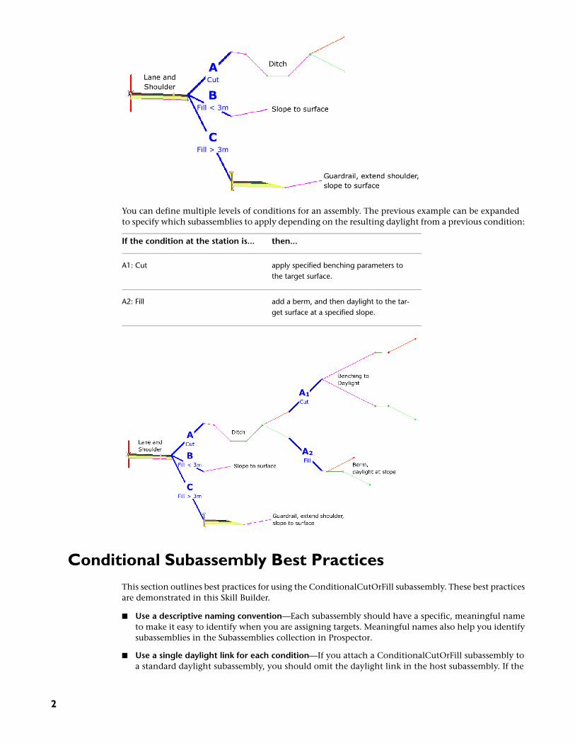
You can define multiple levels of conditions for an assembly. The previous example can be expandedto specify which subassemblies to apply depending on the resulting daylight from a previous condition:
then...If the condition at the station is...
apply specified benching parameters tothe target surface.
A1: Cut
add a berm, and then daylight to the tar-get surface at a specified slope.
A2: Fill
Conditional Subassembly Best PracticesThis section outlines best practices for using the ConditionalCutOrFill subassembly. These best practicesare demonstrated in this Skill Builder.
■ Use a descriptive naming convention—Each subassembly should have a specific, meaningful nameto make it easy to identify when you are assigning targets. Meaningful names also help you identifysubassemblies in the Subassemblies collection in Prospector.
■ Use a single daylight link for each condition—If you attach a ConditionalCutOrFill subassembly toa standard daylight subassembly, you should omit the daylight link in the host subassembly. If the
2

daylight link is included in the host subassembly, then daylight links will be created for both the hostsubassembly and the attached subassembly.
Installing the Skill Builder FilesFor best results, save the files that are included with this Skill Builder the My Documents\Autodesk\SkillBuilders\Conditional Subassembly folder, creating the Conditional Subassembly folder, and the Skill Builders folderif it does not exist. Other Skill Builders for AutoCAD Civil 3D should also go into the Skill Builders folder.
Importing the Conditional SubassemblyIn this exercise, you will download the ConditionalCutOrFill subassembly from the Autodesk SubscriptionCenter website, and then import the subassembly into a new tool palette.
1 From the Autodesk Subscription Center website, download the Imperial ConditionalCutOrFill.pkt file to theMy Documents\Autodesk\Skill Builders\Conditional Subassembly folder.
The PKT file contains all the files necessary for the subassembly to work on your computer.
2 In the AutoCAD Civil 3D window, click File menu ➤ Open. Navigate to the My Documents\Autodesk\SkillBuilders\Conditional Subassembly folder. Open Civil3D_2009_SkillBuilder_Conditional_Subassembly.dwg.
This drawing contains an existing ground surface, an alignment, profiles of the existing ground andproposed finished ground, a corridor, and a corridor assembly. In later exercises, you will modify thecorridor assembly and then examine the results on the corridor.
3 If the Tool Palettes are not visible, on the command line, enter ToolPalettes.
4 In the Civil 3D - Imperial tool palette group, right-click a tool palette tab. Click New Palette.
5 Change the New Palette text to Conditional.
6 Click Corridors menu ➤ Utilities ➤ Import Subassemblies.
7 In the Import Subassemblies dialog box, for Source File, click .
8 In the Select File dialog box, navigate to the My Documents\Autodesk\Skill Builders\Conditional Subassemblyfolder. Select the Imperial ConditionalCutOrFill.pkt file. Click Open.
9 In the Import Subassemblies dialog box, select the Catalog Library/My Imported Tools check box. ClickOK.
The ConditionalCutOrFill subassembly is imported to both the Conditional tool palette and the MyImported Tools tool catalog in Content Browser.
10 Close the Content Browser window.
Examining the Existing Corridor in SectionIn this exercise, you will examine how the daylight subassemblies are applied to the corridor model insection. You will notice stations at which the current daylighting parameters are inappropriate for the siteconditions.
1 Click Corridors menu ➤ View/Edit Corridor Section. In the lower viewport, click the corridor.
2 In the View/Edit Corridor Section Tools toolbar, use the buttons to examine how theThrough Road assembly is applied to at the corridor stations.
Installing the Skill Builder Files | 3
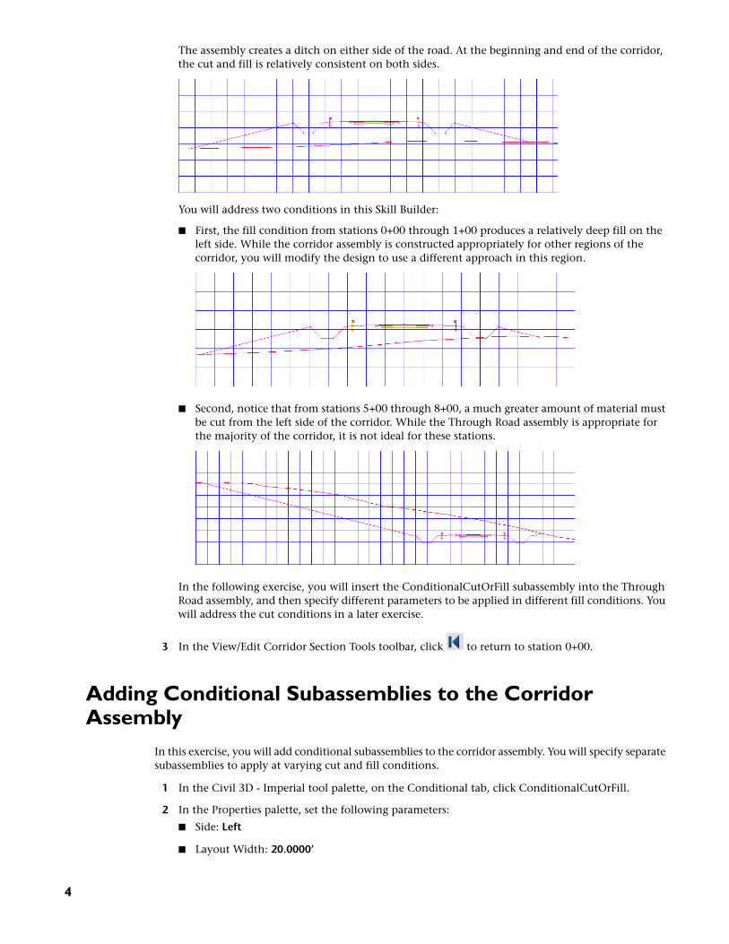
The assembly creates a ditch on either side of the road. At the beginning and end of the corridor,the cut and fill is relatively consistent on both sides.
You will address two conditions in this Skill Builder:
■ First, the fill condition from stations 0+00 through 1+00 produces a relatively deep fill on theleft side. While the corridor assembly is constructed appropriately for other regions of thecorridor, you will modify the design to use a different approach in this region.
■ Second, notice that from stations 5+00 through 8+00, a much greater amount of material mustbe cut from the left side of the corridor. While the Through Road assembly is appropriate forthe majority of the corridor, it is not ideal for these stations.
In the following exercise, you will insert the ConditionalCutOrFill subassembly into the ThroughRoad assembly, and then specify different parameters to be applied in different fill conditions. Youwill address the cut conditions in a later exercise.
3 In the View/Edit Corridor Section Tools toolbar, click to return to station 0+00.
Adding Conditional Subassemblies to the CorridorAssembly
In this exercise, you will add conditional subassemblies to the corridor assembly. You will specify separatesubassemblies to apply at varying cut and fill conditions.
1 In the Civil 3D - Imperial tool palette, on the Conditional tab, click ConditionalCutOrFill.
2 In the Properties palette, set the following parameters:
■ Side: Left
■ Layout Width: 20.0000’
4

■ Layout Grade: 4.000:1
■ Type: Fill
■ Minimum Distance: 0.0000’
■ Maximum Distance: 5.0000’
NOTE The Layout Width and Layout Grade parameters only affect the appearance of the subassembly inlayout view. These parameters enable you to position the conditional subassembly and subassemblies thatare attached to it, but do not affect the corridor model.
3 In the drawing window, in the top viewport, click the left guardrail to add the ConditionalCutOrFillsubassembly.
4 Add a second ConditionalCutOrFill subassembly to the left guardrail using the following parameters:
■ Side: Left
■ Layout Width: 20.0000’
■ Layout Grade: 1.000:1
■ Type: Fill
■ Minimum Distance: 5.0001’
■ Maximum Distance: 9999.0000’
5 Add a third ConditionalCutOrFill subassembly to the left guardrail using the following parameters:
■ Side: Left
■ Layout Width: 20.0000’
■ Layout Grade: 1.000:1
■ Type: Cut
■ Minimum Distance: 0.0000’
■ Maximum Distance: 9999.0000’
6 Using the Imperial - Daylight tool palette, add a DaylightBench subassembly to the Fill 5.00 : 9999.00conditional subassembly using the following parameters:
■ Side: Left
■ Cut Slope: 4.000:1
■ Max Cut Height: 5.0000’
■ Fill Slope: 4.000:1
■ Max Fill Height: 5.0000’
■ Bench Width: 6.0000’
■ Bench Slope: -10.000%
Adding Conditional Subassemblies to the Corridor Assembly | 5

7 Press Esc to exit subassembly placement mode.
8 Select the original left ditch subassembly. Right-click. Click Move To. Click the FIll 0.00 : 5.00conditional subassembly.
9 Select the ditch subassembly that you just moved. Right-click. Click Copy To. Click the Cut 0.00 :9999.00 conditional subassembly.
When you are finished, the assembly should look like this:
Adjusting Subassembly Properties and Assigning MeaningfulNames
In this exercise, you will adjust the properties of two of the subassemblies, and then assign descriptivenames to each of the subassemblies in the Through Road assembly.
Each subassembly should have a specific, meaningful name to make it easy to identify when you areassigning targets. Meaningful names also help you identify subassemblies in the Subassemblies collectionin Prospector.
1 In the drawing window, in the top viewport, select the red assembly marker. Right-click. ClickAssembly Properties.
2 In the Assembly Properties dialog box, click the Construction tab.
Notice that the subassemblies that you added to the left side of the assembly display the defaultnames followed by the side to which they were added. When you build a complex assembly, youshould assign meaningful names to the subassemblies so that you can easily identify them whensetting corridor targets. This is also a good practice when a drawing contains multiple assemblies.
In the following steps, you will give the subassemblies more meaningful names. But first, you willchange a parameter in the ditch subassembly that you copied in the previous exercise.
3 In the Item list, select the DaylightBasin - Left subassembly.
NOTE The Daylight Basin for TR-L subassembly is the original subassembly that you moved in theprevious exercise. Make sure that you select the DaylightBasin - Left subassembly, which should be thelast subassembly in the list.
4 In the Input Values table, change Cut Slope and Fill Slope values to 2.000:1.
5 Repeat Steps 3 and 4 to change the Daylight Basin For TR-L subassembly Cut Slope and Fill Slopevalues to 8:000:1.
NOTE The provided values produce a noticeable variation in slope. The slope variation will be obviouswhen you examine the results in section.
6 In the Item list, select the ConditionalCutOrFill - Left subassembly. Click it again to highlight thetext. Change the name to COND Fill 0-5 for TR-L.
6

7 Rename the other two ConditionalCutOrFill subassemblies to the following names:
■ ConditionalCutOrFill - Left (1): COND Fill 5-9999 for TR-L
■ ConditionalCutOrFill - Left (2): COND Cut 0-9999 for TR-L
8 Rename the daylight subassemblies to reflect the cut or fill condition to which they apply:
■ DaylightBench - Left: Daylight Bench (Fill) for TR-L
■ Daylight Basin for TR-L: Daylight Basin (Fill) for TR-L
■ DaylightBasin - Left: Daylight Basin (Cut) for TR-L
9 Click OK.
Rebuilding the Corridor and Examining the ResultsIn this exercise, you will reset the corridor targets, rebuild the corridor, and then examine how the conditionalsubassembly affects the corridor model.
1 In Toolspace, on the Prospector tab, expand the Corridors collection. Right-click Corridor - (1). ClickProperties.
2 In the Corridor Properties dialog box, on the Parameters tab, click Set All Targets.
3 In the Target Mapping dialog box, in the Object Name column, click <Click Here To Set All>.
4 In the Pick A Surface dialog box, click Existing Ground.
5 Click OK three times to close the dialog boxes and rebuild the corridor.
6 In the View/Edit Corridor Section Tools toolbar, click to return to station 0+00.
The corridor at station 0+00 is in a relatively deep fill condition. In Adding Conditional Subassembliesto the Corridor Assembly on page 4, you attached the daylight bench subassembly to the Fill 5.00:9999.00 conditional subassembly. The fill condition at this station is greater than 5.0001’, so the daylightbench subassembly is applied.
7 Click six times to advance to station 1+50.
Notice that at station 1+50, the corridor is in a relatively shallow fill condition. You attached the originaldaylight basin subassembly to the Fill 0.00 : 9999.00 conditional subassembly. The fill condition at thisstation is less than 5.00’, so the daylight basin subassembly is applied. Notice that the daylight slopeis very flat, because you specified an 8.000:1 slope for this condition.
Rebuilding the Corridor and Examining the Results | 7
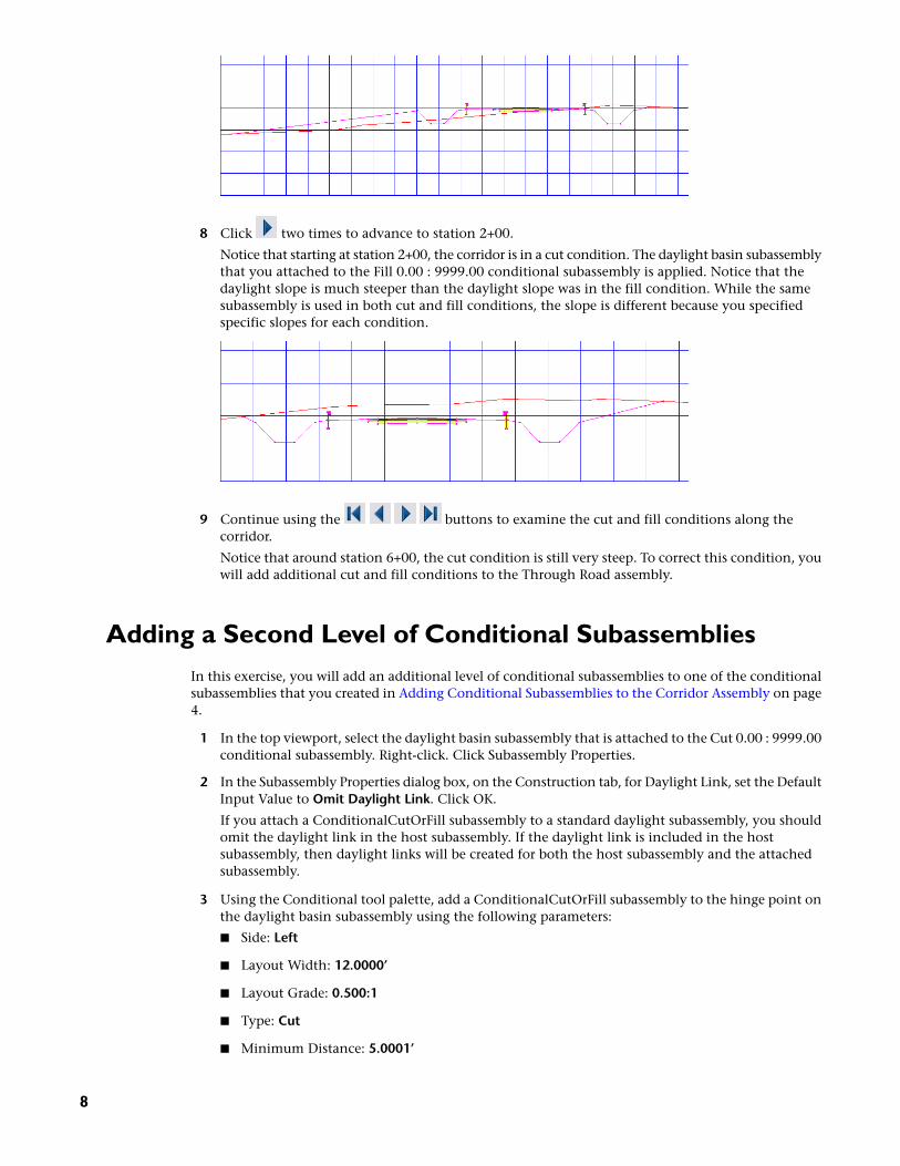
8 Click two times to advance to station 2+00.
Notice that starting at station 2+00, the corridor is in a cut condition. The daylight basin subassemblythat you attached to the Fill 0.00 : 9999.00 conditional subassembly is applied. Notice that thedaylight slope is much steeper than the daylight slope was in the fill condition. While the samesubassembly is used in both cut and fill conditions, the slope is different because you specifiedspecific slopes for each condition.
9 Continue using the buttons to examine the cut and fill conditions along thecorridor.
Notice that around station 6+00, the cut condition is still very steep. To correct this condition, youwill add additional cut and fill conditions to the Through Road assembly.
Adding a Second Level of Conditional SubassembliesIn this exercise, you will add an additional level of conditional subassemblies to one of the conditionalsubassemblies that you created in Adding Conditional Subassemblies to the Corridor Assembly on page4.
1 In the top viewport, select the daylight basin subassembly that is attached to the Cut 0.00 : 9999.00conditional subassembly. Right-click. Click Subassembly Properties.
2 In the Subassembly Properties dialog box, on the Construction tab, for Daylight Link, set the DefaultInput Value to Omit Daylight Link. Click OK.
If you attach a ConditionalCutOrFill subassembly to a standard daylight subassembly, you shouldomit the daylight link in the host subassembly. If the daylight link is included in the hostsubassembly, then daylight links will be created for both the host subassembly and the attachedsubassembly.
3 Using the Conditional tool palette, add a ConditionalCutOrFill subassembly to the hinge point onthe daylight basin subassembly using the following parameters:
■ Side: Left
■ Layout Width: 12.0000’
■ Layout Grade: 0.500:1
■ Type: Cut
■ Minimum Distance: 5.0001’
8

■ Maximum Distance: 9999.0000’
4 Add a second ConditionalCutOrFill subassembly to the hinge point on the daylight basin subassemblyusing the following parameters:
■ Side: Left
■ Layout Width: 12.0000’
■ Layout Grade: 1.000:1
■ Type: Cut
■ Minimum Distance: 0.0000’
■ Maximum Distance: 5.0000’
5 Add a third ConditionalCutOrFill subassembly to the hinge point on the daylight basin subassemblyusing the following parameters:
■ Side: Left
■ Layout Width: 12.0000’
■ Layout Grade: 1.000:1
■ Type: Fill
■ Minimum Distance: 0.0000’
■ Maximum Distance: 9999.0000’
6 Using the Imperial - Generic tool palette, add a LinkWidthAndSlope subassembly to the Cut 5.00 :9999.00 conditional subassembly using the following parameters:
■ Side: Left
■ Width: 12.0000’
■ Slope: -2.000%
7 Using the Imperial - Structures tool palette, add a RetainWallVertical subassembly to theLinkWidthAndSlope subassembly using the default parameters.
8 Using the Imperial - Generic tool palette, add a LinkOffsetOnSurface subassembly to the Cut 0.00 : 5.00conditional subassembly using the following parameters:
■ Offset From Baseline: -60.000’
■ Omit Link: No
Adding a Second Level of Conditional Subassemblies | 9

9 Using the Imperial - Generic tool palette, add a LinkSlopeToSurface subassembly to the Fill 0.00 :9999.00 conditional subassembly using the following parameters:
■ Side: Left
■ Slope: 4.000%
■ Add Link In: Fill Only
NOTE The Fill 0.00 : 9999.00 conditional subassembly that is attached to the Cut branch of the assemblywill be applied if the daylight basin subassembly were to end in a fill condition.
10 Press Esc to exit subassembly placement mode.
When you are finished, the assembly should look like this:
Naming the Second Level of Conditional SubassembliesWhen an assembly has multiple levels of conditions, managing the subassemblies and assigning targetscan become confusing. Applying a consistent, descriptive naming convention to all subassemblies helpsmitigate confusion.
NOTE This exercise is optional. For this Skill Builder, it is not critical that the subassemblies have specificnames. However, it is a good practice to assign meaningful subassembly names when you are working on areal project.
Using the same steps that you did in Adjusting Subassembly Properties and Assigning Meaningful Nameson page 6, give the subassemblies the following names:
■ ConditionalCutOrFill - Left: COND Cut 0-9999 -- Cut 5-9999 for TR-L
■ ConditionalCutOrFill - Left (3): COND Cut 0-9999 -- Cut 0-5 for TR-L
■ ConditionalCutOrFill - Left (4): COND Fill 0-9999 -- Cut 0-9999 for TR-L
■ LinkWidthAndSlope - Left: Daylight Width Slope (Cut 0-9999 -- Cut 5-9999) for TR-L
■ RetainWallVertical - Left: Retaining Wall (Cut 0-9999 -- Cut 5-9999) for TR-L
■ LinkOffsetOnSurface: Daylight Offset To Surface (Cut 0-9999 -- Cut 0-5) for TR-L
■ LinkSlopeToSurface - Left: Daylight Slope To Surface (Cut 0-9999 -- Fill 0-9999) for TR-L
10
Rebuilding the Corridor and Examining the ResultsIn this exercise, you will reset the corridor targets, rebuild the corridor, and then examine how the multiplebranches of the conditional subassembly affect the corridor model.
1 In Toolspace, on the Prospector tab, expand the Corridors collection. Right-click Corridor - (1). ClickProperties.
2 In the Corridor Properties dialog box, on the Parameters tab, click Set All Targets.
3 In the Target Mapping dialog box, in the Object Name column, click <Click Here To Set All>.
4 In the Pick A Surface dialog box, click Existing Ground.
5 Click OK three times to close the dialog boxes and rebuild the corridor.
6 In the View/Edit Corridor Section Tools toolbar, click to return to station 0+00.
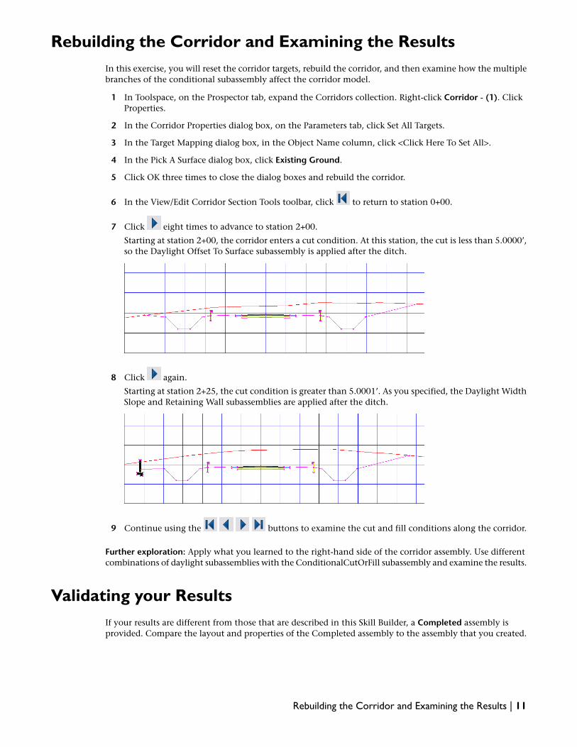
7 Click eight times to advance to station 2+00.
Starting at station 2+00, the corridor enters a cut condition. At this station, the cut is less than 5.0000’,so the Daylight Offset To Surface subassembly is applied after the ditch.
8 Click again.
Starting at station 2+25, the cut condition is greater than 5.0001’. As you specified, the Daylight WidthSlope and Retaining Wall subassemblies are applied after the ditch.
9 Continue using the buttons to examine the cut and fill conditions along the corridor.
Further exploration: Apply what you learned to the right-hand side of the corridor assembly. Use differentcombinations of daylight subassemblies with the ConditionalCutOrFill subassembly and examine the results.
Validating your ResultsIf your results are different from those that are described in this Skill Builder, a Completed assembly isprovided. Compare the layout and properties of the Completed assembly to the assembly that you created.
Rebuilding the Corridor and Examining the Results | 11
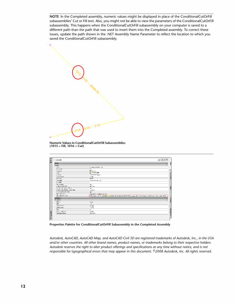
NOTE In the Completed assembly, numeric values might be displayed in place of the ConditionalCutOrFillsubassemblies’ Cut or Fill text. Also, you might not be able to view the parameters of the ConditionalCutOrFillsubassembly. This happens when the ConditionalCutOrFill subassembly on your computer is saved to adifferent path than the path that was used to insert them into the Completed assembly. To correct theseissues, update the path shown in the .NET Assembly Name Parameter to reflect the location to which yousaved the ConditionalCutOrFill subassembly.
Numeric Values in ConditionalCutOrFill Subassemblies(1015 = Fill, 1016 = Cut)
Properties Palette for ConditionalCutOrFill Subassembly in the Completed Assembly
Autodesk, AutoCAD, AutoCAD Map, and AutoCAD Civil 3D are registered trademarks of Autodesk, Inc., in the USAand/or other countries. All other brand names, product names, or trademarks belong to their respective holders.Autodesk reserves the right to alter product offerings and specifications at any time without notice, and is notresponsible for typographical errors that may appear in this document. ©2008 Autodesk, Inc. All rights reserved.
12