Civil 2010 (v1.1)Release Note - · PDF fileWood-Armer moment calculation is one of the most...
32
midas Civil Enhancement 1 / 32 Civil 2010 (v1.1)Release Note Civil 2010 (v1.1) Release Note Integrated Solution System for Bridge and Civil Engineering
Transcript of Civil 2010 (v1.1)Release Note - · PDF fileWood-Armer moment calculation is one of the most...
midas Civil Enhancement
1 / 32
Civil 2010 (v1.1)Release Note
Civil 2010 (v1.1)Release NoteIntegrated Solut ion System for Bridge and Civil Engineering

Enhancements
Pre/Post Processing
1. Addition of Grillage Model Wizard
2. Tapered Section Group can be defined for General Composite Section
3. Inputted tendon profile can be displayed at cross sections in a real scale
4. Wood-Armer Moment Calculation for Plate Elements
5. Automeshing
and much more…
Analysis part
1. Applying Plate and Solid Elements to Structural Masonry Material
2. Addition of Multi-Linear Type Elastic Link
3. Addition of Constraint Table in Unknown Load Factor
4. Addition of Cable Force Tuning Function
and much more…
Design part
1. Addition of AASHTO LRFD PSC Design
2. Addition of EC2-2:2005 Pier Design
and much more…
3
20
29
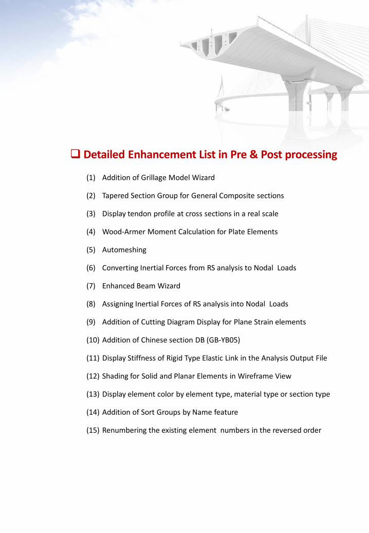
(1) Addition of Grillage Model Wizard
(2) Tapered Section Group for General Composite sections
(3) Display tendon profile at cross sections in a real scale
(4) Wood-Armer Moment Calculation for Plate Elements
(5) Automeshing
(6) Converting Inertial Forces from RS analysis to Nodal Loads
(7) Enhanced Beam Wizard
(8) Assigning Inertial Forces of RS analysis into Nodal Loads
(9) Addition of Cutting Diagram Display for Plane Strain elements
(10) Addition of Chinese section DB (GB-YB05)
(11) Display Stiffness of Rigid Type Elastic Link in the Analysis Output File
(12) Shading for Solid and Planar Elements in Wireframe View
(13) Display element color by element type, material type or section type
(14) Addition of Sort Groups by Name feature
(15) Renumbering the existing element numbers in the reversed order
Detailed Enhancement List in Pre & Post processing
midas Civil Enhancement
4 / 32
Civil 2010 (v1.1)Release Note
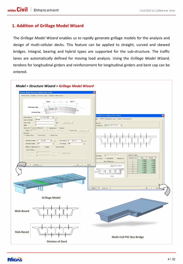
1. Addition of Grillage Model Wizard
Model > Structure Wizard > Grillage Model Wizard
Grillage Model
Multi-Cell PSC Box Bridge
The Grillage Model Wizard enables us to rapidly generate grillage models for the analysis and
design of multi-cellular decks. This feature can be applied to straight, curved and skewed
bridges. Integral, bearing and hybrid types are supported for the sub-structure. The traffic
lanes are automatically defined for moving load analysis. Using the Grillage Model Wizard,
tendons for longitudinal girders and reinforcement for longitudinal girders and bent cap can be
entered.
Division of Deck
Web-Based
Slab-Based
midas Civil Enhancement
5 / 32
Civil 2010 (v1.1)Release Note
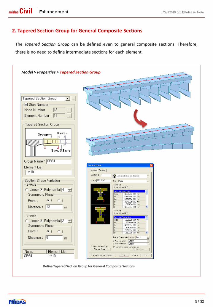
2. Tapered Section Group for General Composite Sections
The Tapered Section Group can be defined even to general composite sections. Therefore,
there is no need to define intermediate sections for each element.
Define Tapered Section Group for General Composite Sections
Model > Properties > Tapered Section Group
midas Civil Enhancement
6 / 32
Civil 2010 (v1.1)Release Note
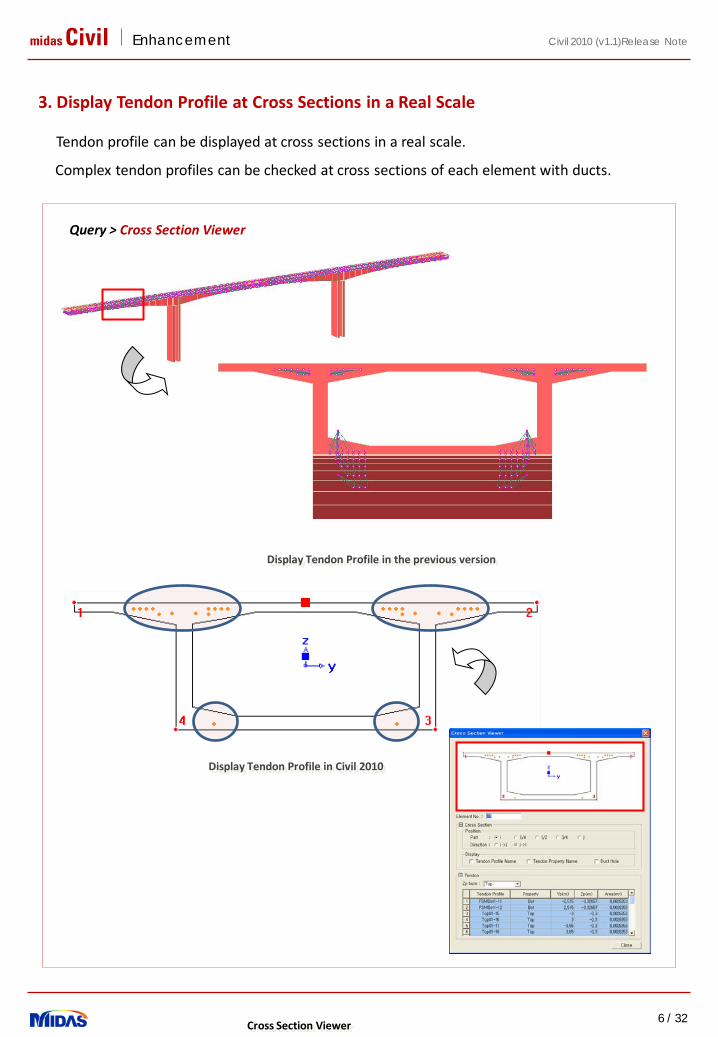
3. Display Tendon Profile at Cross Sections in a Real Scale
Query > Cross Section Viewer
Tendon profile can be displayed at cross sections in a real scale.
Complex tendon profiles can be checked at cross sections of each element with ducts.
Display Tendon Profile in the previous version
Cross Section Viewer
Display Tendon Profile in Civil 2010

midas Civil Enhancement
7 / 32
Civil 2010 (v1.1)Release Note
4. Wood-Armer Moment Calculation for Plate Elements
Results > Forces > Plate Forces/Moments
Wood-Armer moment calculation is one of the most popular design methods that explicitly
incorporate twisting moments in slab design. By using Wood-Armer moments in midas Civil,
accurate reinforcement quantities can be calculated. Wood-Armer moments can be calculated
for any direction of reinforcement in the top and bottom faces of slabs.
midas Civil Enhancement
8 / 32
Civil 2010 (v1.1)Release Note
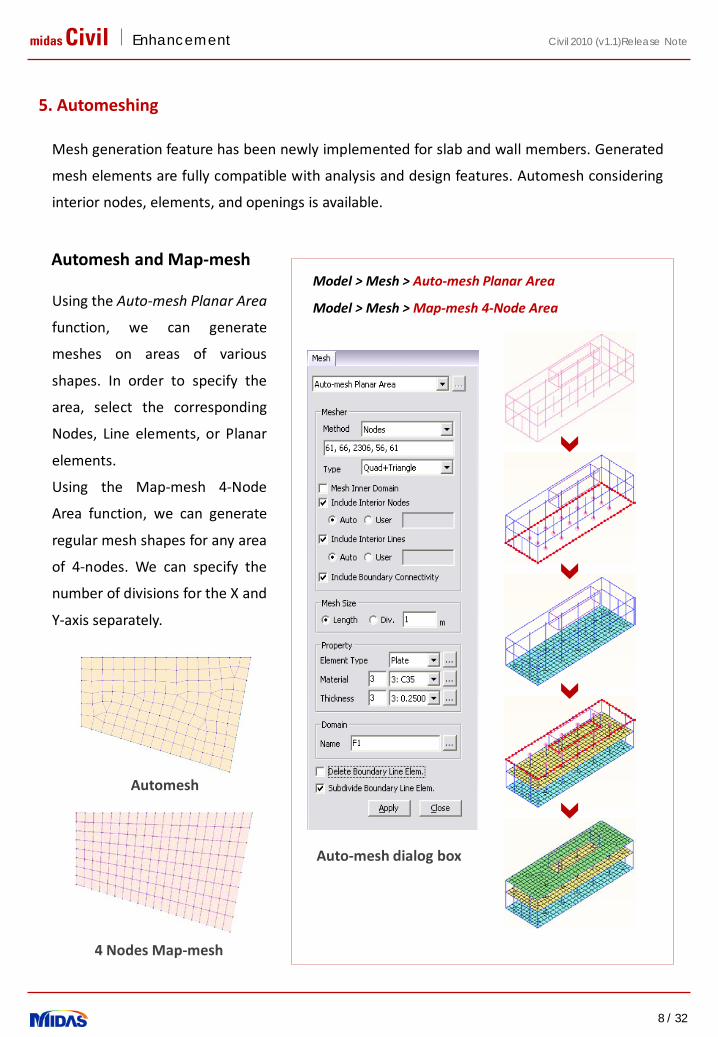
Mesh generation feature has been newly implemented for slab and wall members. Generated
mesh elements are fully compatible with analysis and design features. Automesh considering
interior nodes, elements, and openings is available.
Auto-mesh dialog box
Using the Auto-mesh Planar Area
function, we can generate
meshes on areas of various
shapes. In order to specify the
area, select the corresponding
Nodes, Line elements, or Planar
elements.
Using the Map-mesh 4-Node
Area function, we can generate
regular mesh shapes for any area
of 4-nodes. We can specify the
number of divisions for the X and
Y-axis separately.
Automesh and Map-mesh
5. Automeshing
Model > Mesh > Auto-mesh Planar Area
Model > Mesh > Map-mesh 4-Node Area
Automesh
4 Nodes Map-mesh
midas Civil Enhancement
9 / 32
Civil 2010 (v1.1)Release Note
Meshing
Meshing
Meshing
Meshing
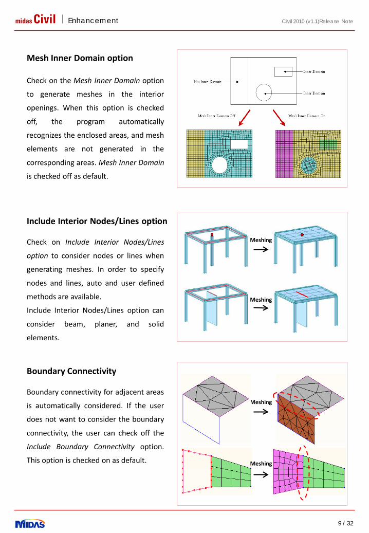
Check on the Mesh Inner Domain option
to generate meshes in the interior
openings. When this option is checked
off, the program automatically
recognizes the enclosed areas, and mesh
elements are not generated in the
corresponding areas. Mesh Inner Domain
is checked off as default.
Mesh Inner Domain option
Include Interior Nodes/Lines option
Check on Include Interior Nodes/Lines
option to consider nodes or lines when
generating meshes. In order to specify
nodes and lines, auto and user defined
methods are available.
Include Interior Nodes/Lines option can
consider beam, planer, and solid
elements.
Boundary Connectivity
Boundary connectivity for adjacent areas
is automatically considered. If the user
does not want to consider the boundary
connectivity, the user can check off the
Include Boundary Connectivity option.
This option is checked on as default.

midas Civil Enhancement
10 / 32
Civil 2010 (v1.1)Release Note
Meshing
Meshing
Meshing
Check on the Delete Boundary Line
Element option to delete line elements
when generating meshes. When this
option is checked off and the Subdivide
Source Line Element option is checked on,
line elements will be divided relevant to
the mesh size.
Delete Boundary Line Element
When mesh elements are generated,
boundary line elements are divided
relevant to the mesh size. Divided line
elements are assigned as one member for
design.
This option is activated when Delete
Source Line Element option is checked off.
Subdivide Boundary Line Element
When mesh elements are generated,
predefined loads are automatically
redistributed along the mesh elements.
Redistribute pressure loads
midas Civil Enhancement
11 / 32
Civil 2010 (v1.1)Release Note
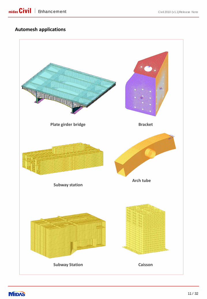
Automesh applications
Arch tube
Bracket
Subway station
CaissonSubway Station
Plate girder bridge
midas Civil Enhancement
12 / 32
Civil 2010 (v1.1)Release Note
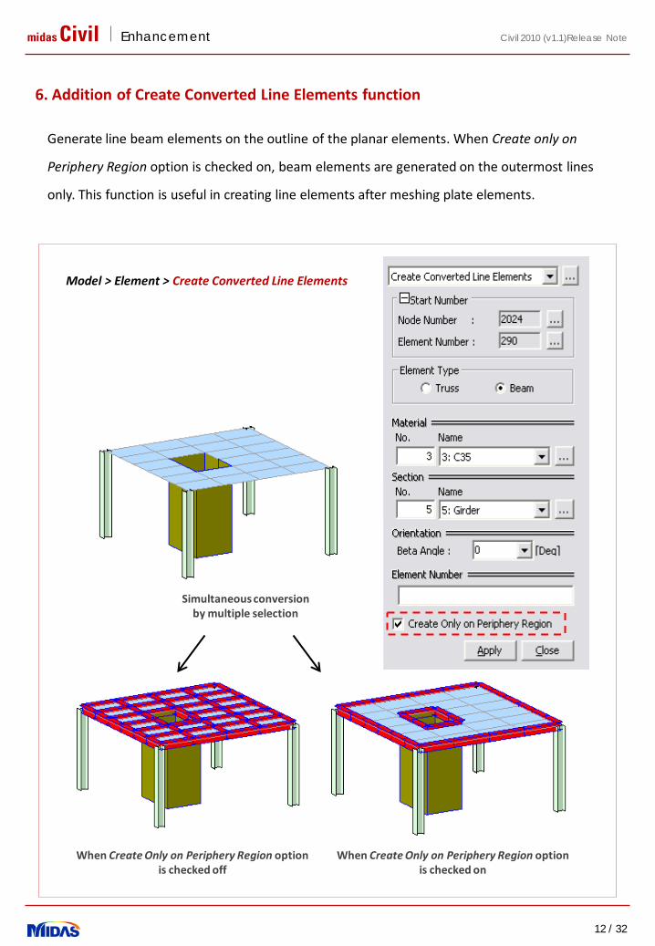
Generate line beam elements on the outline of the planar elements. When Create only on
Periphery Region option is checked on, beam elements are generated on the outermost lines
only. This function is useful in creating line elements after meshing plate elements.
Simultaneous conversion by multiple selection
When Create Only on Periphery Region option is checked on
When Create Only on Periphery Region option is checked off
Model > Element > Create Converted Line Elements
6. Addition of Create Converted Line Elements function
midas Civil Enhancement
13 / 32
Civil 2010 (v1.1)Release Note
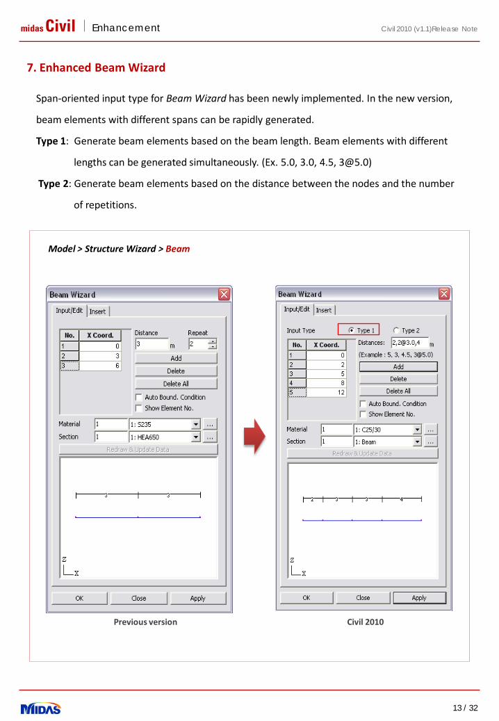
Model > Structure Wizard > Beam
Previous version Civil 2010
7. Enhanced Beam Wizard
Span-oriented input type for Beam Wizard has been newly implemented. In the new version,
beam elements with different spans can be rapidly generated.
Type 1: Generate beam elements based on the beam length. Beam elements with different
lengths can be generated simultaneously. (Ex. 5.0, 3.0, 4.5, [email protected])
Type 2: Generate beam elements based on the distance between the nodes and the number
of repetitions.
midas Civil Enhancement
14 / 32
Civil 2010 (v1.1)Release Note
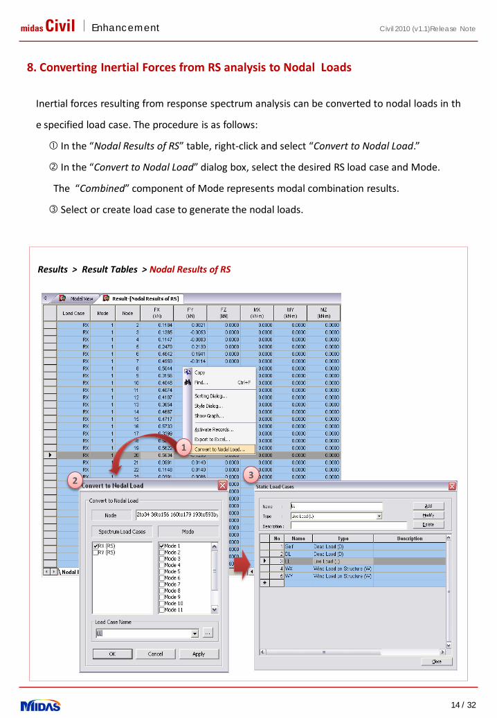
Inertial forces resulting from response spectrum analysis can be converted to nodal loads in th
e specified load case. The procedure is as follows:
In the “Nodal Results of RS” table, right-click and select “Convert to Nodal Load.”
In the “Convert to Nodal Load” dialog box, select the desired RS load case and Mode.
The “Combined” component of Mode represents modal combination results.
Select or create load case to generate the nodal loads.
Results > Result Tables > Nodal Results of RS
8. Converting Inertial Forces from RS analysis to Nodal Loads
32
1
midas Civil Enhancement
15 / 32
Civil 2010 (v1.1)Release Note
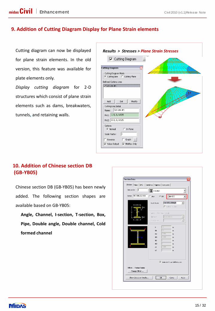
Cutting diagram can now be displayed
for plane strain elements. In the old
version, this feature was available for
plate elements only.
Display cutting diagram for 2-D
structures which consist of plane strain
elements such as dams, breakwaters,
tunnels, and retaining walls.
Results > Stresses > Plane Strain Stresses
9. Addition of Cutting Diagram Display for Plane Strain elements
Chinese section DB (GB-YB05) has been newly
added. The following section shapes are
available based on GB-YB05:
Angle, Channel, I-section, T-section, Box,
Pipe, Double angle, Double channel, Cold
formed channel
10. Addition of Chinese section DB(GB-YB05)
midas Civil Enhancement
16 / 32
Civil 2010 (v1.1)Release Note
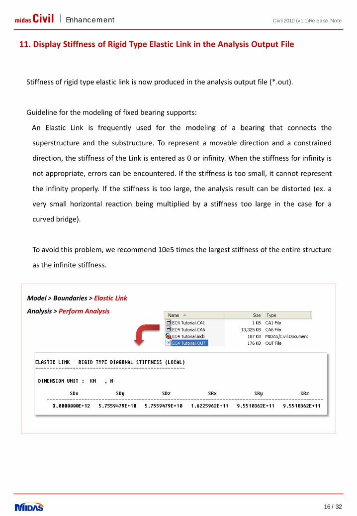
Model > Boundaries > Elastic Link
Analysis > Perform Analysis
Stiffness of rigid type elastic link is now produced in the analysis output file (*.out).
Guideline for the modeling of fixed bearing supports:
An Elastic Link is frequently used for the modeling of a bearing that connects the
superstructure and the substructure. To represent a movable direction and a constrained
direction, the stiffness of the Link is entered as 0 or infinity. When the stiffness for infinity is
not appropriate, errors can be encountered. If the stiffness is too small, it cannot represent
the infinity properly. If the stiffness is too large, the analysis result can be distorted (ex. a
very small horizontal reaction being multiplied by a stiffness too large in the case for a
curved bridge).
To avoid this problem, we recommend 10e5 times the largest stiffness of the entire structure
as the infinite stiffness.
11. Display Stiffness of Rigid Type Elastic Link in the Analysis Output File
midas Civil Enhancement
17 / 32
Civil 2010 (v1.1)Release Note
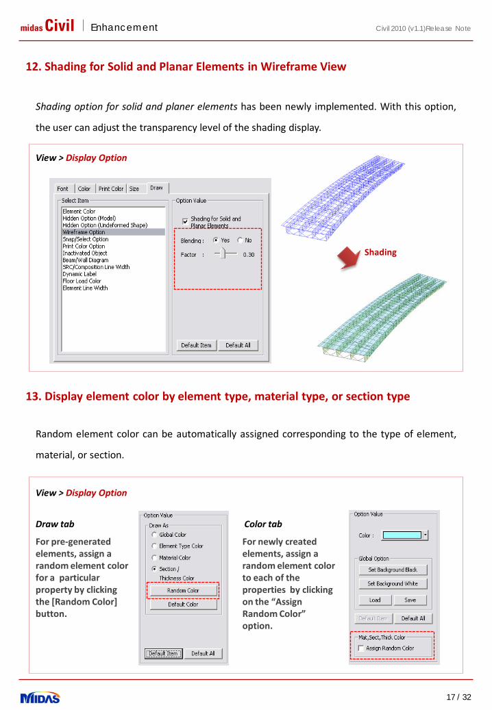
View > Display Option
Shading option for solid and planer elements has been newly implemented. With this option,
the user can adjust the transparency level of the shading display.
12. Shading for Solid and Planar Elements in Wireframe View
Random element color can be automatically assigned corresponding to the type of element,
material, or section.
For pre-generated elements, assign a random element color for a particular property by clicking the [Random Color] button.
For newly created elements, assign a random element color to each of the properties by clicking on the “Assign Random Color” option.
View > Display Option
13. Display element color by element type, material type, or section type
Draw tab Color tab
Shading
midas Civil Enhancement
18 / 32
Civil 2010 (v1.1)Release Note
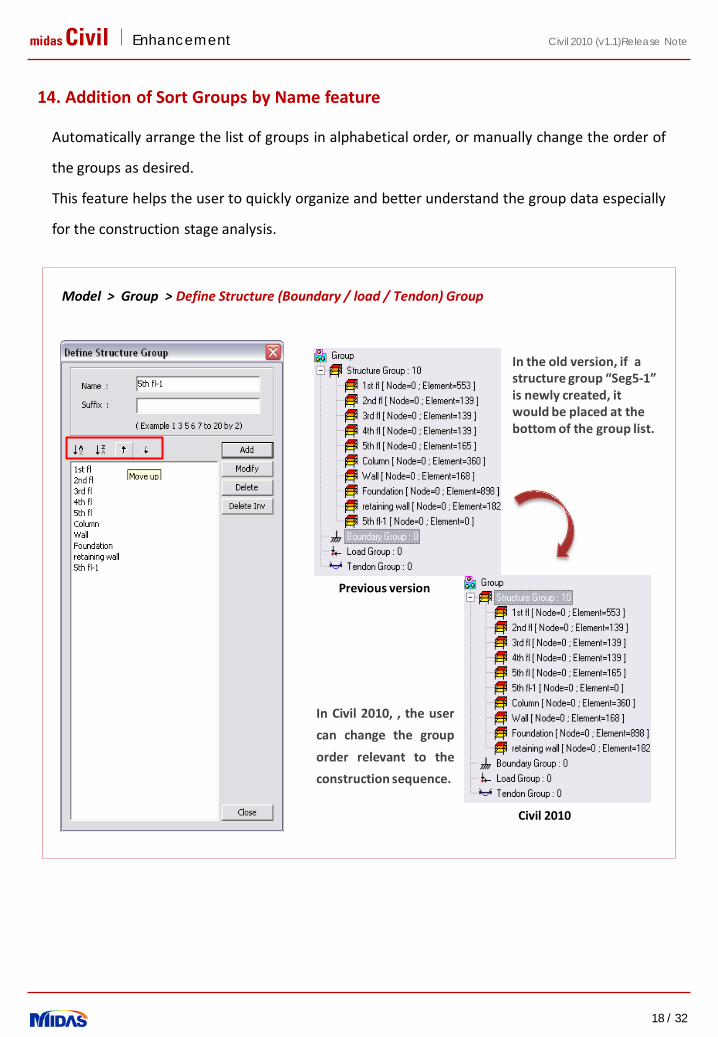
In the old version, if a structure group “Seg5-1” is newly created, it would be placed at the bottom of the group list.
In Civil 2010, , the user
can change the group
order relevant to the
construction sequence.
Model > Group > Define Structure (Boundary / load / Tendon) Group
Automatically arrange the list of groups in alphabetical order, or manually change the order of
the groups as desired.
This feature helps the user to quickly organize and better understand the group data especially
for the construction stage analysis.
Previous version
Civil 2010
14. Addition of Sort Groups by Name feature
midas Civil Enhancement
19 / 32
Civil 2010 (v1.1)Release Note
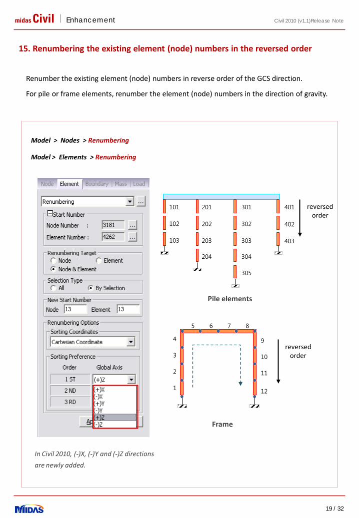
In Civil 2010, (-)X, (-)Y and (-)Z directions
are newly added.
102
103
201
202
203
204
301
302
303
304
305
401
402
403
101 reversed order
1
2
3
4
5 6 7 8
9
10
11
12
reversed order
Model > Nodes > Renumbering
Renumber the existing element (node) numbers in reverse order of the GCS direction.
For pile or frame elements, renumber the element (node) numbers in the direction of gravity.
Model > Elements > Renumbering
Pile elements
Frame
15. Renumbering the existing element (node) numbers in the reversed order
(1) Applying Plate and Solid Elements to Structural Masonry Material
(2) Addition of Multi-Linear Type Elastic Link
(3) Addition of Constraint Table in Unknown Load Factor
(4) Addition of Cable Force Tuning Function
(5) Considering Mass Participation Factor for Rotational direction
(6) Enhanced pushover hinge properties of FEMA type
(7) Addition of Vehicle Type for the Australian Standard
(8) Improvements in Inelastic Hinge Properties of SRC Beam member
Detailed Enhancement List in Analysis

midas Civil Enhancement
21 / 32
Civil 2010 (v1.1)Release Note
1. Applying Plate and Solid Elements to Structural Masonry Material
Plate elements, 4-nodes tetra solid, and 6-nodes wedge solid elements can be applied to the
Structural Masonry material for plastic analysis.
Model > Properties > Plastic Material
midas Civil Enhancement
22 / 32
Civil 2010 (v1.1)Release Note
P
δ
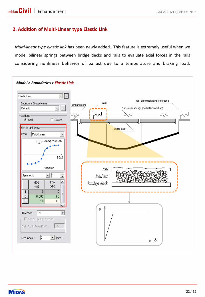
2. Addition of Multi-Linear type Elastic Link
Multi-linear type elastic link has been newly added. This feature is extremely useful when we
model bilinear springs between bridge decks and rails to evaluate axial forces in the rails
considering nonlinear behavior of ballast due to a temperature and braking load.
Model > Boundaries > Elastic Link
midas Civil Enhancement
23 / 32
Civil 2010 (v1.1)Release Note
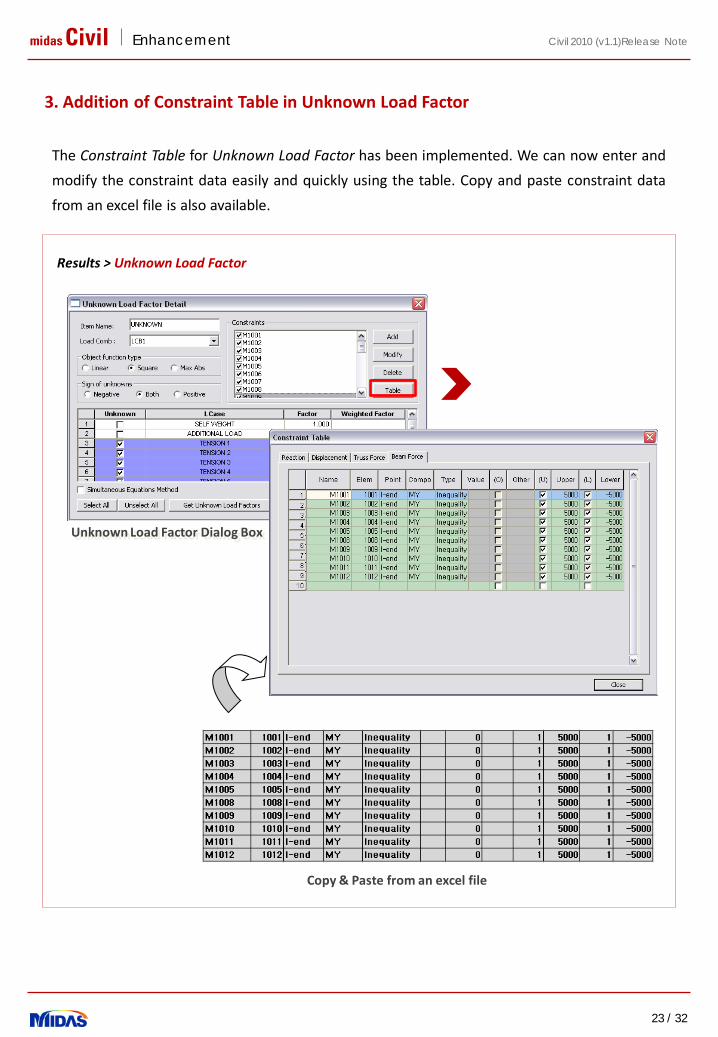
3. Addition of Constraint Table in Unknown Load Factor
The Constraint Table for Unknown Load Factor has been implemented. We can now enter and
modify the constraint data easily and quickly using the table. Copy and paste constraint data
from an excel file is also available.
Results > Unknown Load Factor
Copy & Paste from an excel file
Unknown Load Factor Dialog Box
midas Civil Enhancement
24 / 32
Civil 2010 (v1.1)Release Note
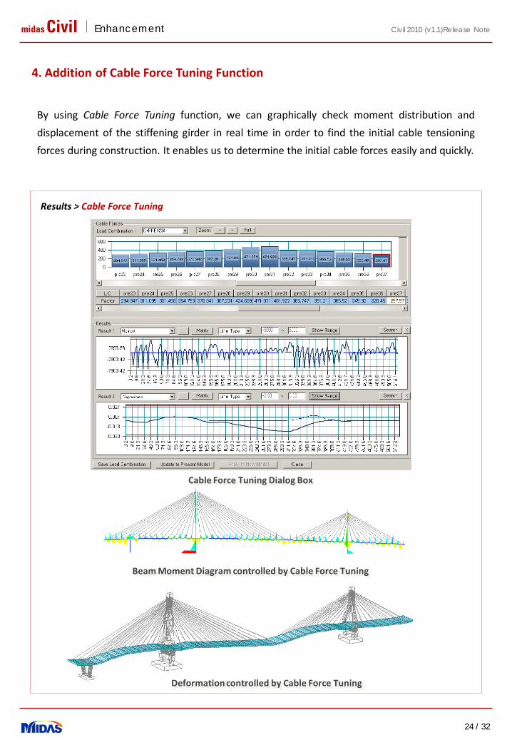
4. Addition of Cable Force Tuning Function
Results > Cable Force Tuning
Cable Force Tunnig 기능
Deformation controlled by Cable Force Tuning
By using Cable Force Tuning function, we can graphically check moment distribution and
displacement of the stiffening girder in real time in order to find the initial cable tensioning
forces during construction. It enables us to determine the initial cable forces easily and quickly.
Cable Force Tuning Dialog Box
Beam Moment Diagram controlled by Cable Force Tuning
midas Civil Enhancement
25 / 32
Civil 2010 (v1.1)Release Note
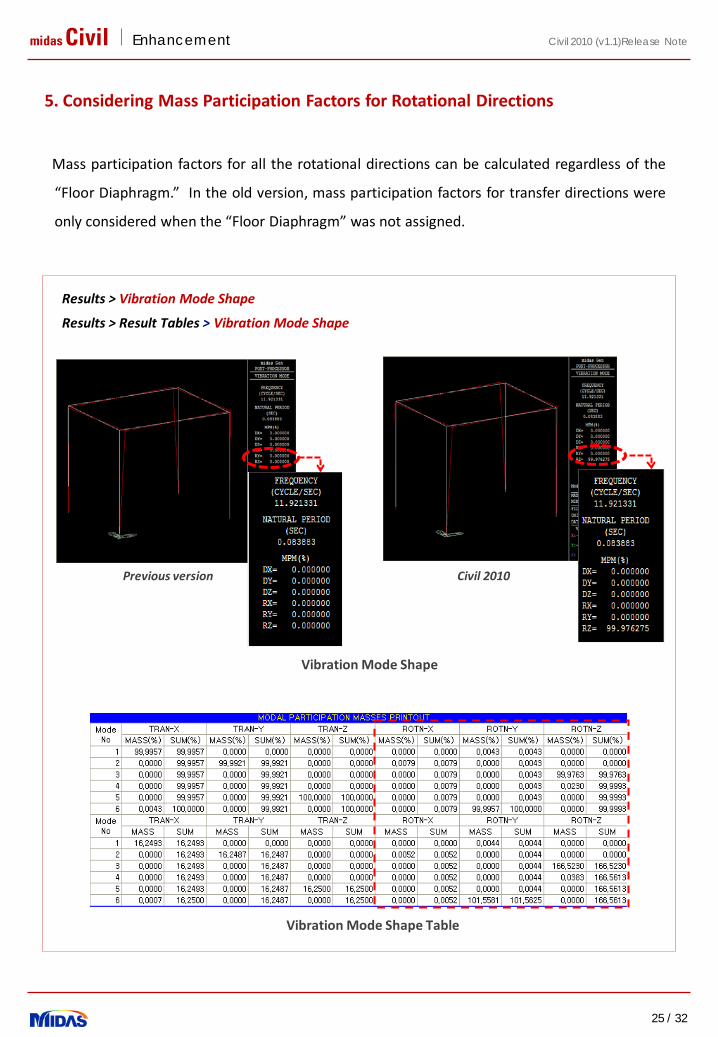
5. Considering Mass Participation Factors for Rotational Directions
Mass participation factors for all the rotational directions can be calculated regardless of the
“Floor Diaphragm.” In the old version, mass participation factors for transfer directions were
only considered when the “Floor Diaphragm” was not assigned.
Results > Vibration Mode Shape
Results > Result Tables > Vibration Mode Shape
Previous version Civil 2010
Vibration Mode Shape
Vibration Mode Shape Table

midas Civil Enhancement
26 / 32
Civil 2010 (v1.1)Release Note
6. Enhanced pushover hinge properties of FEMA type
In the old version, M/MY at the point D and E must have the same value. In Civil 2010,
different values can be defined. This is applicable when the Interaction Type is “None” and the
Input Method is “User Input.”
This function is implemented to support the integration between SERCB win and midas Civil.
Design > Pushover analysis > Define Pushover Hinge Properties
[Pushover analysis result in Civil]
[SERCB win]

midas Civil Enhancement
27 / 32
Civil 2010 (v1.1)Release Note
7. Addition of Vehicle Type for the Australian Standard
Vehicle types, M1600 and S1600, according to the Australian Standard have been
implemented. Australian vehicle can be defined with the following procedure:
(1) Define the Moving Load Code as AASHTO Standard, AASHTO LRFD or PENNDOT.
(2) Define the Vehicles using [Add Standard] button.
(3) Select the Standard Name as ‘Others’.
(4) Select Vehicular Load Type as M1600 or S1600
Load > Moving Load Analysis Data > Vehicles
1 2
3
4
Vehicle M1600
Vehicle S1600

midas Civil Enhancement
28 / 32
Civil 2010 (v1.1)Release Note
8. Improvements in Inelastic Hinge Properties of SRC Beam member
Inelastic hinge can now be defined for SRC(encased) beam members. In the old version,
inelastic hinge was not able to be assigned to SRC(encased) beam elements.
Model > Properties > Inelastic Hinge Properties

Detailed Enhancement List in Design part
(1) Addition of AASHTO LRFD PSC Design
(2) Addition of EC2-2:2005 Column Design
(3) Addition of new rebar DB UNI standard
(4) Improvement in calculating effective length in the steel structure
midas Civil Enhancement
30 / 32
Civil 2010 (v1.1)Release Note
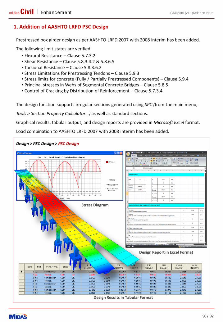
1. Addition of AASHTO LRFD PSC Design
Design > PSC Design > PSC Design
Prestressed box girder design as per AASHTO LRFD 2007 with 2008 interim has been added.
The following limit states are verified: • Flexural Resistance – Clause 5.7.3.2• Shear Resistance – Clause 5.8.3.4.2 & 5.8.6.5• Torsional Resistance – Clause 5.8.3.6.2• Stress Limitations for Prestressing Tendons – Clause 5.9.3• Stress limits for concrete (Fully / Partially Prestressed Components) – Clause 5.9.4• Principal stresses in Webs of Segmental Concrete Bridges – Clause 5.8.5• Control of Cracking by Distribution of Reinforcement – Clause 5.7.3.4
The design function supports irregular sections generated using SPC (from the main menu,
Tools > Section Property Calculator…) as well as standard sections.
Graphical results, tabular output, and design reports are provided in Microsoft Excel format.
Load combination to AASHTO LRFD 2007 with 2008 interim has been added.
Design Report in Excel Format
Design Results in Tabular Format
Stress Diagram
midas Civil Enhancement
31 / 32
Civil 2010 (v1.1)Release Note
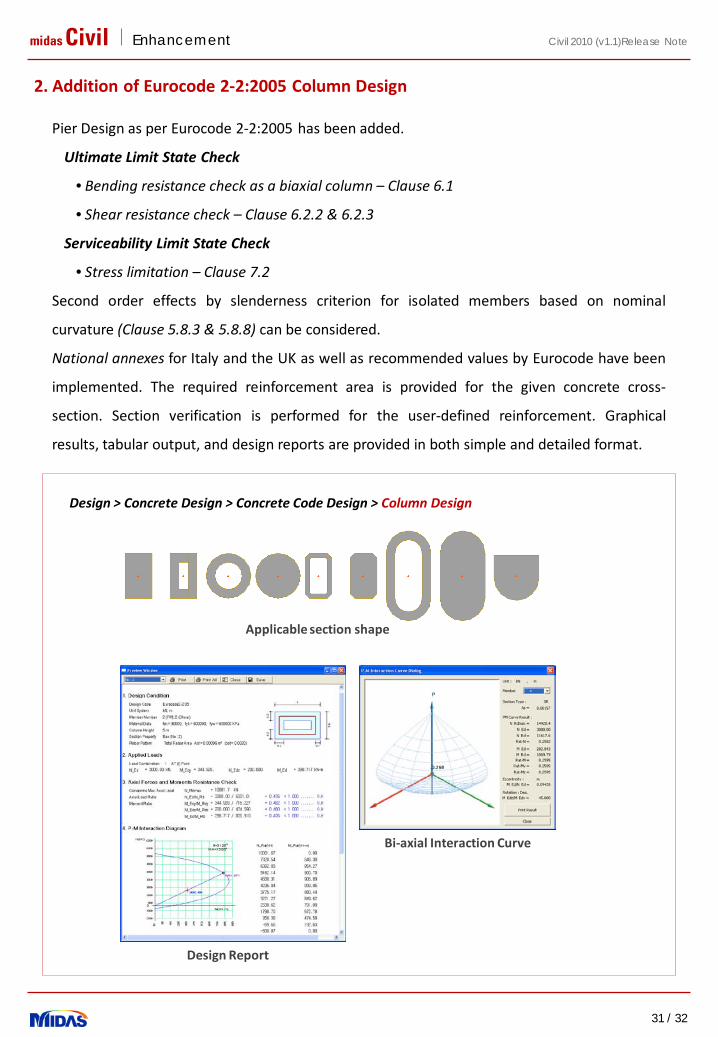
Pier Design as per Eurocode 2-2:2005 has been added.
Ultimate Limit State Check
• Bending resistance check as a biaxial column – Clause 6.1
• Shear resistance check – Clause 6.2.2 & 6.2.3
Serviceability Limit State Check
• Stress limitation – Clause 7.2
Second order effects by slenderness criterion for isolated members based on nominal
curvature (Clause 5.8.3 & 5.8.8) can be considered.
National annexes for Italy and the UK as well as recommended values by Eurocode have been
implemented. The required reinforcement area is provided for the given concrete cross-
section. Section verification is performed for the user-defined reinforcement. Graphical
results, tabular output, and design reports are provided in both simple and detailed format.
2. Addition of Eurocode 2-2:2005 Column Design
Design > Concrete Design > Concrete Code Design > Column Design
Applicable section shape
Design Report
Bi-axial Interaction Curve
midas Civil Enhancement
32 / 32
Civil 2010 (v1.1)Release Note
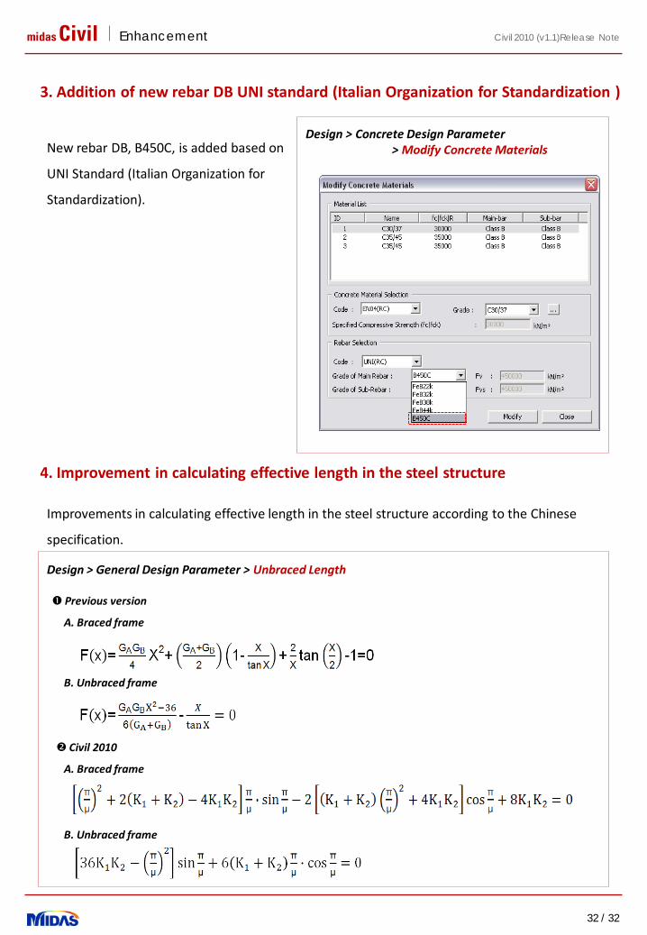
Improvements in calculating effective length in the steel structure according to the Chinese
specification.
3. Addition of new rebar DB UNI standard (Italian Organization for Standardization )
New rebar DB, B450C, is added based on
UNI Standard (Italian Organization for
Standardization).
Design > Concrete Design Parameter > Modify Concrete Materials
4. Improvement in calculating effective length in the steel structure
Design > General Design Parameter > Unbraced Length
Previous version
A. Braced frame
B. Unbraced frame
Civil 2010
A. Braced frame
B. Unbraced frame


![r ii e Wl Un] armer](https://static.fdocuments.in/doc/165x107/61ac6328daca41020c13911b/r-ii-e-wl-un-armer.jpg)