
CITY UTILITIES DESIGN STANDARDS MANUAL · line would end in a drop manhole structure as opposed to...
17
CITY UTILITIES DESIGN STANDARDS MANUAL Book 3 Sanitary (SA) SA5 Sewer Design June 2015
Transcript of CITY UTILITIES DESIGN STANDARDS MANUAL · line would end in a drop manhole structure as opposed to...

CITY UTILITIES DESIGN STANDARDS MANUAL
Book 3
Sanitary (SA)
SA5 Sewer Design
June 2015

City Utilities Design Standards Manual Book 3 Chapter SA5 Sanitary Sewer Design
June 1, 2015 1
SA5.01 Purpose
This Chapter focuses on the design elements and basic hydraulic criteria necessary for the proper design of sanitary sewers. This Chapter establishes the minimum standards and technical design criteria for all City of Fort Wayne sanitary sewers. All variances from these design standards must be approved prior to commencement of design in compliance with Chapter GR3 - Variances.
1. Basic Elements of Design
Horizontal alignment to efficiently provide service to existing and potential sanitary sewer users.
Vertical alignment with consideration of service depth, minimum cover, depth of additional sewers within the system, underground utility conflicts, constructability and system hydraulics.
Total design flow with consideration of existing and future population served by the sanitary sewer.
Sewer size, material, bedding, and construction method.
Necessary appurtenances and additional structures required for a complete and maintainable system.
2. Covered in this Chapter
General Improvement Location Criteria
Horizontal Alignment Criteria
Vertical Alignment Criteria
Pipe Bedding
Pipe Materials
Design Flow
Hydraulic Design Criteria
Downstream Capacity Evaluation
Sewer Pipe Criteria
Inverted Siphons
Connections of New Sewers to Existing Sewers
3. Covered in Other Chapters
Chapter SA6 – Building Sewer and Appurtenance Design
Chapter SA7 – Manhole Design
Chapter SA8 – Lift Station and Force Main Design
SA5.02 General Improvement Location Criteria
General location criteria of proposed sewer alignment to be considered should include, but not be limited to the following:
Use existing rights-of-way and/or City Utility easements whenever possible.
Thoroughly evaluate service needs of both present service area and future service area.
Serve entire tributary area in best way possible.

City Utilities Design Standards Manual Book 3 Chapter SA5 Sanitary Sewer Design
June 1, 2015 2
Elevation requirements to provide service to first floor of buildings, with consideration that service to basements may not be an option due to depth, constructability and cost.
Existing underground and overhead utilities, roadways and railroads.
Proposed utilities such as sewer, stormwater and water facilities.
Environmentally sensitive areas including creeks, rivers, wetlands, trees, protected habitats, etc.
Easement requirements, property values, and potential damages to all affected properties.
Potential development and utility or street extensions into adjacent areas.
100-year flood elevations and regulatory floodways.
Continuity with adjacent design segments.
Maintenance of traffic during construction.
Availability of materials.
Subsurface conditions: soils and ground water.
Access for maintenance.
SA5.03 Horizontal Alignment Criteria
In general, sanitary sewers should be located on the opposite side of the street from the water main. Sanitary sewers are generally located on the south and east sides of the public right-of-way.
Every effort should be made to locate the sewer outside of the pavement, but within existing or proposed right-of-way.
1. Placement in Existing Right-of-Way
For sanitary sewers located within existing or proposed street right-of-way, the preferred placement should be as generally defined on the following Standard Drawing:
Exhibit SA5-1 Recommended Utility Placement in Public Right-of-Way
Allowances for future curb and gutter should be made.
The existence of curbs or proposed curbs and gutter should be taken into account when evaluating the benefit of reducing the number of manhole in curve streets.
In areas with concrete pavement, consider placing the sewer such that one edge of the pavement to be removed coincides with existing construction joints.
Manhole structures shall be either completely outside the pavement or completely within the pavement.
2. Placement Outside of Existing Right-of-Way
Where sewers cannot be placed within right-of-way, easements shall be procured.

City Utilities Design Standards Manual Book 3 Chapter SA5 Sanitary Sewer Design
June 1, 2015 3
Figure SA5.1 – Minimum Easement Widths
Recommended Minimum Easement Width for
Depths <18’
Size of Pipe Permanent Temporary Total
8" – 12" 20' 15' on each side 50'
15" - 48" 20' 20' on each side 60'
54" - 72" 25' 25' on each side 75'
84" and larger 30' 30' on each side 90'
Recommended Minimum Easement Width for Depths >18’
Size of Pipe Permanent Temporary Total
8" – 12" 30' 15' on each side 60'
15" - 48" 30' 25' on each side 80'
54" - 72" 30' 30' on each side 90'
84" and larger 40' 30' on each side 100'
3. Minimum Horizontal Separation from Water Mains
Refer to Standard Drawing BS-7 Sewer and Water Main Separation
A 10- foot horizontal distance edge to edge shall be maintained between sanitary sewer and existing or proposed water main per Title 327 IAC 8-3.2-9.
The crossing must maintain a minimum angle of 45 degrees measured from the centerlines of the sanitary sewer and water main.
If it is not possible to maintain the 10-foot separation, the following design criteria shall apply: A. Installation of the sanitary sewer closer to the water main may
be approved, provided that the water main is in a separate trench or on an undisturbed earth shelf located on one side of the sewer and at an elevation such that the bottom of the water main is at least 18 inches above the top of the sanitary sewer.
B. The sewer shall be constructed of water main grade pipe material from manhole to manhole, with pressure rated joints complying with Title 327 IAC 8-3.2-8. All water main grade pipe material requirements are defined in Chapter MA7 –Water Materials.
C. Either the sewer or water main shall be encased in a watertight casing pipe which extends for a minimum distance of 10 feet from either side of the water main or sewer as measured from
City Utilities Design Standards Manual Book 3 Chapter SA5 Sanitary Sewer Design
June 1, 2015 4
the outside edge of the water main to the outside edge of the sewer.
D. If the deviation described above is not possible, both the water main and sanitary sewer must be constructed of pipe material and joints complying with Title 327 IAC 8-3.2-8 Water Main Material per Title 327 IAC 3-6-9 Separation of Collection Systems from Water Mains and Drinking Water Wells.
4. Rear Lot Alignment
In certain limited situations, rear lot sanitary sewer alignment may be considered and approved by variance.
Where rear lot alignment is used, a utility or sanitary easement shall be required and the sewer shall not be located within drainage swales.
5. Minimum Distance from Utilities Other than Water Mains
All drawings shall show the location of both underground and overhead utilities.
Utility locations shall be derived from the most reliable and up-to-date information.
Each utility shall receive a set of drawings prior to final submittal. On these drawings, they may note changes or addition to utility information.
Separation distance of sanitary sewer from other utilities shall be determined by the representative of other utilities and the applicant.
Any necessary relocation shall be closely coordinated with the respective utility representative.
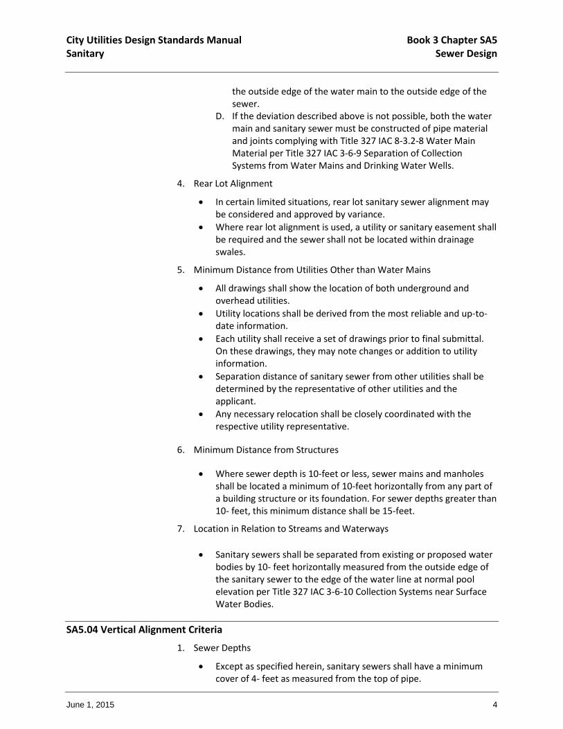
6. Minimum Distance from Structures
Where sewer depth is 10-feet or less, sewer mains and manholes shall be located a minimum of 10-feet horizontally from any part of a building structure or its foundation. For sewer depths greater than 10- feet, this minimum distance shall be 15-feet.
7. Location in Relation to Streams and Waterways
Sanitary sewers shall be separated from existing or proposed water bodies by 10- feet horizontally measured from the outside edge of the sanitary sewer to the edge of the water line at normal pool elevation per Title 327 IAC 3-6-10 Collection Systems near Surface Water Bodies.
SA5.04 Vertical Alignment Criteria
1. Sewer Depths
Except as specified herein, sanitary sewers shall have a minimum cover of 4- feet as measured from the top of pipe.
City Utilities Design Standards Manual Book 3 Chapter SA5 Sanitary Sewer Design
June 1, 2015 5
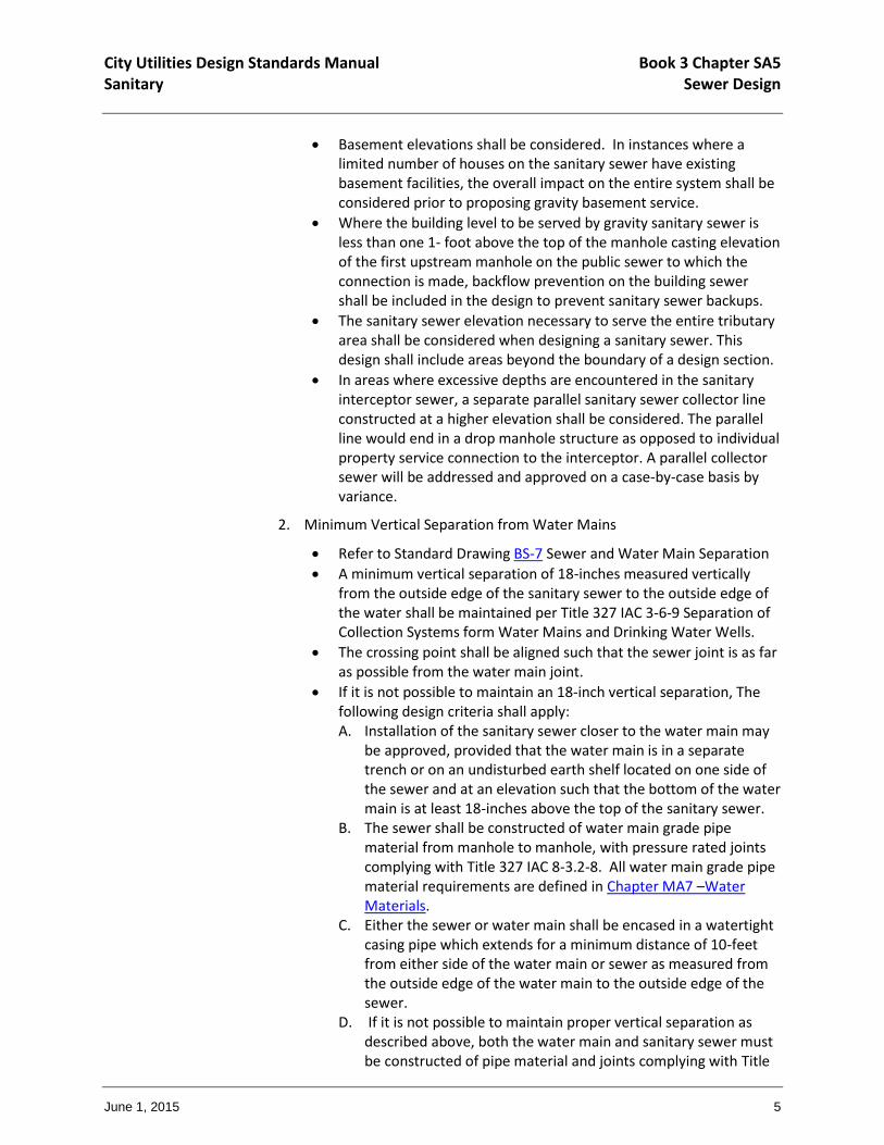
Basement elevations shall be considered. In instances where a limited number of houses on the sanitary sewer have existing basement facilities, the overall impact on the entire system shall be considered prior to proposing gravity basement service.
Where the building level to be served by gravity sanitary sewer is less than one 1- foot above the top of the manhole casting elevation of the first upstream manhole on the public sewer to which the connection is made, backflow prevention on the building sewer shall be included in the design to prevent sanitary sewer backups.
The sanitary sewer elevation necessary to serve the entire tributary area shall be considered when designing a sanitary sewer. This design shall include areas beyond the boundary of a design section.
In areas where excessive depths are encountered in the sanitary interceptor sewer, a separate parallel sanitary sewer collector line constructed at a higher elevation shall be considered. The parallel line would end in a drop manhole structure as opposed to individual property service connection to the interceptor. A parallel collector sewer will be addressed and approved on a case-by-case basis by variance.
2. Minimum Vertical Separation from Water Mains
Refer to Standard Drawing BS-7 Sewer and Water Main Separation
A minimum vertical separation of 18-inches measured vertically from the outside edge of the sanitary sewer to the outside edge of the water shall be maintained per Title 327 IAC 3-6-9 Separation of Collection Systems form Water Mains and Drinking Water Wells.
The crossing point shall be aligned such that the sewer joint is as far as possible from the water main joint.
If it is not possible to maintain an 18-inch vertical separation, The following design criteria shall apply: A. Installation of the sanitary sewer closer to the water main may
be approved, provided that the water main is in a separate trench or on an undisturbed earth shelf located on one side of the sewer and at an elevation such that the bottom of the water main is at least 18-inches above the top of the sanitary sewer.
B. The sewer shall be constructed of water main grade pipe material from manhole to manhole, with pressure rated joints complying with Title 327 IAC 8-3.2-8. All water main grade pipe material requirements are defined in Chapter MA7 –Water Materials.
C. Either the sewer or water main shall be encased in a watertight casing pipe which extends for a minimum distance of 10-feet from either side of the water main or sewer as measured from the outside edge of the water main to the outside edge of the sewer.
D. If it is not possible to maintain proper vertical separation as described above, both the water main and sanitary sewer must be constructed of pipe material and joints complying with Title

City Utilities Design Standards Manual Book 3 Chapter SA5 Sanitary Sewer Design
June 1, 2015 6
327 IAC 8-3.2-8 Water Main Material per Title 327 IAC 3-6-9 Separation of Collection Systems from Water Mains and Drinking Water Wells.
E. Every effort shall be made to construct the sanitary sewer below the water main.
F. If a water main must cross beneath a sanitary sewer, this requires an alternative technical standard per IDEM on a case-by-case basis. Structural support, exfiltration testing of the water main to ensure its integrity, and/or relocation of the water main to maintain a vertical separation distance of 36-inches may be required.
3. Stream and Waterway Crossings
Sanitary sewers located under surface water bodies shall meet the following and comply with Title 327 IAC 3-6-10 Collection Systems near Surface Water Bodies:
Sanitary sewers located under surface water bodies shall be constructed of ductile iron pipe or PVC having a DR of 21 and in conformance with ASTM D2241-96b, with mechanical joints rated to two hundred (200) psi and backfilled with crushed limestone or coarse aggregate.
A minimum of 3-feet of cover shall be provided.
In paved stream channels, the top of the sewer shall be placed below the bottom of the channel pavement.
Cross perpendicular to the stream flow.
Have no change in grade.
SA5.05 Pipe Bedding and Backfill
See Standard Drawing BS-4 General Rigid Pipe Bedding Detail.
See Standard Drawing BS-5 General Flexible Pipe Bedding Detail.
See Standard Drawing BS-6 Ductile Iron Pipe Trench Section.
Refer to Chapter MA4 – Common Materials for typical materials used in sanitary sewer projects.
SA5.06 Pipe Materials
Refer to Chapter MA6 – Sanitary Sewer Materials and Testing Requirements for typical materials used in sanitary sewer projects.
SA5.07 Design Flow
In general, sanitary sewers shall be designed to accommodate the peak hourly flow within the sewer system.
1. Average Daily Flow (ADF)
The design of all sanitary sewer facilities shall take into account both existing and projected future developments.
City Utilities Design Standards Manual Book 3 Chapter SA5 Sanitary Sewer Design
June 1, 2015 7
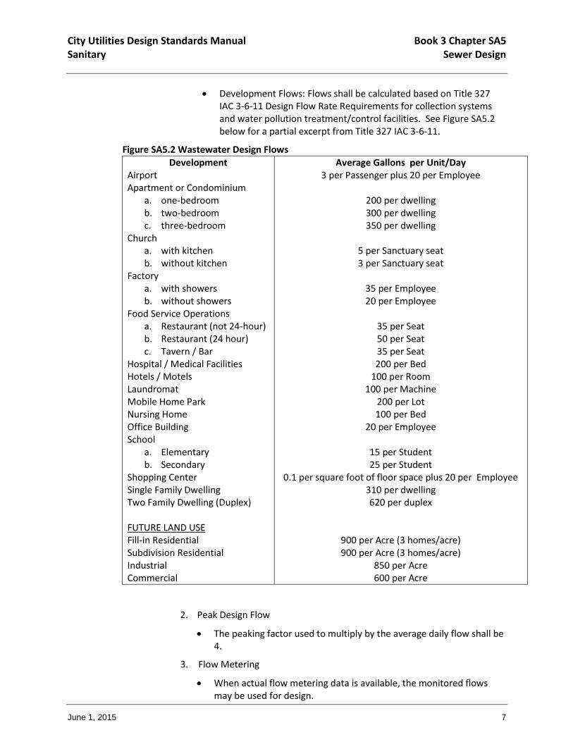
Development Flows: Flows shall be calculated based on Title 327 IAC 3-6-11 Design Flow Rate Requirements for collection systems and water pollution treatment/control facilities. See Figure SA5.2 below for a partial excerpt from Title 327 IAC 3-6-11.
Figure SA5.2 Wastewater Design Flows
Development Airport Apartment or Condominium
a. one-bedroom b. two-bedroom c. three-bedroom
Church a. with kitchen b. without kitchen
Factory a. with showers b. without showers
Food Service Operations a. Restaurant (not 24-hour) b. Restaurant (24 hour) c. Tavern / Bar
Hospital / Medical Facilities Hotels / Motels Laundromat Mobile Home Park Nursing Home Office Building School
a. Elementary b. Secondary
Shopping Center Single Family Dwelling Two Family Dwelling (Duplex) FUTURE LAND USE Fill-in Residential Subdivision Residential Industrial Commercial
Average Gallons per Unit/Day 3 per Passenger plus 20 per Employee
200 per dwelling 300 per dwelling 350 per dwelling
5 per Sanctuary seat 3 per Sanctuary seat
35 per Employee 20 per Employee
35 per Seat 50 per Seat 35 per Seat 200 per Bed
100 per Room 100 per Machine
200 per Lot 100 per Bed
20 per Employee
15 per Student 25 per Student
0.1 per square foot of floor space plus 20 per Employee 310 per dwelling 620 per duplex
900 per Acre (3 homes/acre) 900 per Acre (3 homes/acre)
850 per Acre 600 per Acre
2. Peak Design Flow
The peaking factor used to multiply by the average daily flow shall be 4.
3. Flow Metering
When actual flow metering data is available, the monitored flows may be used for design.
City Utilities Design Standards Manual Book 3 Chapter SA5 Sanitary Sewer Design
June 1, 2015 8
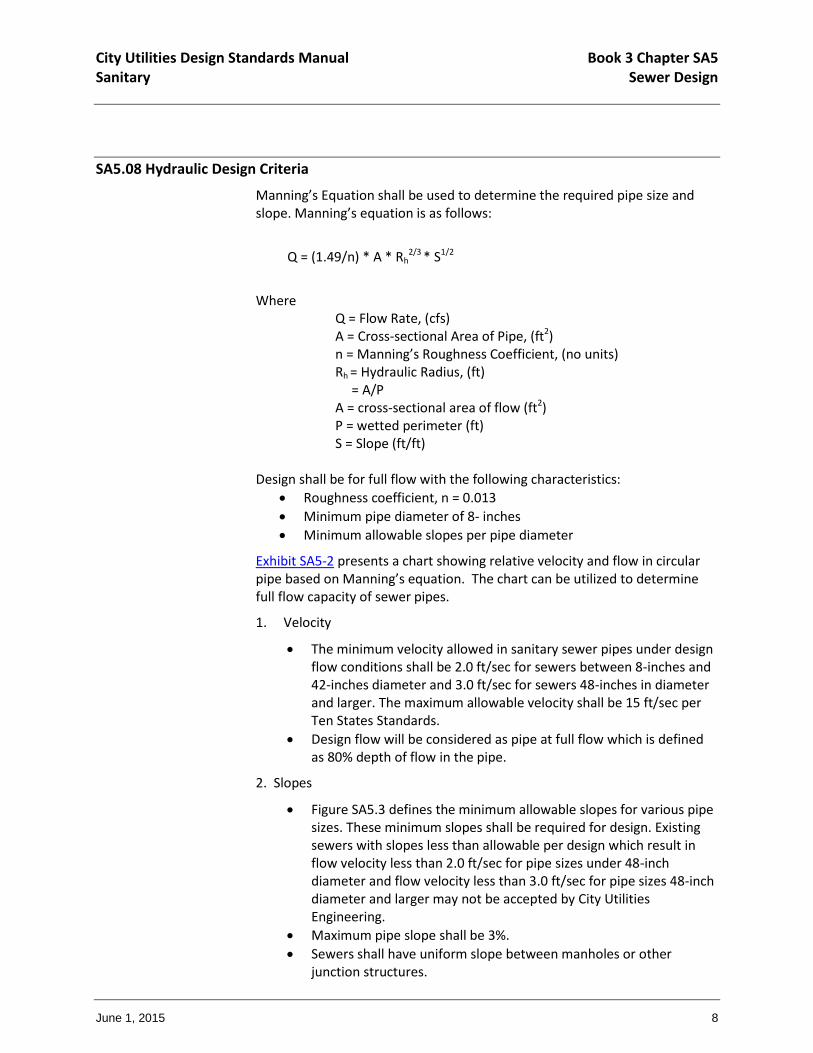
SA5.08 Hydraulic Design Criteria
Manning’s Equation shall be used to determine the required pipe size and slope. Manning’s equation is as follows:
Q = (1.49/n) * A * Rh2/3 * S1/2
Where Q = Flow Rate, (cfs) A = Cross-sectional Area of Pipe, (ft2) n = Manning’s Roughness Coefficient, (no units) Rh = Hydraulic Radius, (ft)
= A/P A = cross-sectional area of flow (ft2) P = wetted perimeter (ft)
S = Slope (ft/ft) Design shall be for full flow with the following characteristics:
Roughness coefficient, n = 0.013
Minimum pipe diameter of 8- inches
Minimum allowable slopes per pipe diameter
Exhibit SA5-2 presents a chart showing relative velocity and flow in circular pipe based on Manning’s equation. The chart can be utilized to determine full flow capacity of sewer pipes.
1. Velocity
The minimum velocity allowed in sanitary sewer pipes under design flow conditions shall be 2.0 ft/sec for sewers between 8-inches and 42-inches diameter and 3.0 ft/sec for sewers 48-inches in diameter and larger. The maximum allowable velocity shall be 15 ft/sec per Ten States Standards.
Design flow will be considered as pipe at full flow which is defined as 80% depth of flow in the pipe.
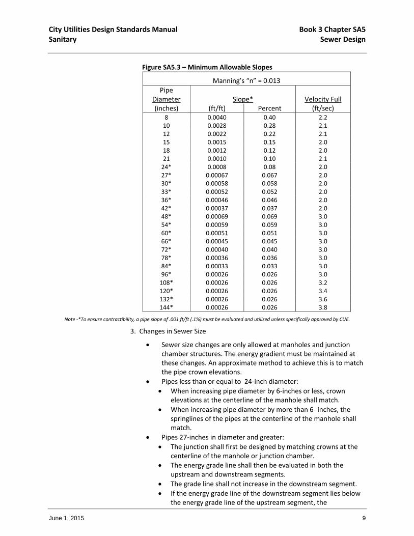
2. Slopes
Figure SA5.3 defines the minimum allowable slopes for various pipe sizes. These minimum slopes shall be required for design. Existing sewers with slopes less than allowable per design which result in flow velocity less than 2.0 ft/sec for pipe sizes under 48-inch diameter and flow velocity less than 3.0 ft/sec for pipe sizes 48-inch diameter and larger may not be accepted by City Utilities Engineering.
Maximum pipe slope shall be 3%.
Sewers shall have uniform slope between manholes or other junction structures.
City Utilities Design Standards Manual Book 3 Chapter SA5 Sanitary Sewer Design
June 1, 2015 9
Figure SA5.3 – Minimum Allowable Slopes
Manning’s “n” = 0.013
Pipe Diameter
Slope*
Velocity Full
(inches) (ft/ft) Percent (ft/sec) 8 0.0040 0.40 2.2
10 0.0028 0.28 2.1 12 0.0022 0.22 2.1 15 0.0015 0.15 2.0 18 0.0012 0.12 2.0 21 0.0010 0.10 2.1
24* 0.0008 0.08 2.0 27* 0.00067 0.067 2.0 30* 0.00058 0.058 2.0 33* 0.00052 0.052 2.0 36* 0.00046 0.046 2.0 42* 0.00037 0.037 2.0 48* 0.00069 0.069 3.0 54* 0.00059 0.059 3.0 60* 0.00051 0.051 3.0 66* 0.00045 0.045 3.0 72* 0.00040 0.040 3.0 78* 0.00036 0.036 3.0 84* 0.00033 0.033 3.0 96* 0.00026 0.026 3.0
108* 0.00026 0.026 3.2 120* 0.00026 0.026 3.4 132* 0.00026 0.026 3.6 144* 0.00026 0.026 3.8
Note -*To ensure contractibility, a pipe slope of .001 ft/ft (.1%) must be evaluated and utilized unless specifically approved by CUE.
3. Changes in Sewer Size
Sewer size changes are only allowed at manholes and junction chamber structures. The energy gradient must be maintained at these changes. An approximate method to achieve this is to match the pipe crown elevations.
Pipes less than or equal to 24-inch diameter:
When increasing pipe diameter by 6-inches or less, crown elevations at the centerline of the manhole shall match.
When increasing pipe diameter by more than 6- inches, the springlines of the pipes at the centerline of the manhole shall match.
Pipes 27-inches in diameter and greater:
The junction shall first be designed by matching crowns at the centerline of the manhole or junction chamber.
The energy grade line shall then be evaluated in both the upstream and downstream segments.
The grade line shall not increase in the downstream segment.
If the energy grade line of the downstream segment lies below the energy grade line of the upstream segment, the

City Utilities Design Standards Manual Book 3 Chapter SA5 Sanitary Sewer Design
June 1, 2015 10
downstream sewer may be raised by two-thirds of the difference between the upstream and downstream grade lines.
4. Minimization of Solids Deposition
The pipe diameter and slope shall be selected to obtain the greatest practical flow velocities to minimize solids deposition. Sewer shall not be oversized to allow for construction on a flatter slope. If the proposed slope is less than the minimum slope of the smallest pipe which could properly accommodate the peak hourly design flow, a variance shall be obtained prior to approval.
SA5.09 Downstream Capacity Evaluation
To evaluate the downstream capacity of a receiving sanitary sewer, City Utilities Engineering will rely on the following:
1. Available Data/Information
Existing number of customers connected to existing sewer
Existing flow monitoring data
Sanitary sewer studies
Maintenance records
Complaint records
Past and/or proposed Capital Improvement Projects
Any other information deemed relevant by City Utilities Engineering
2. Additional Data/Information
If adequate data/information is not available, the applicant may be required to conduct, at no cost to the City, all the necessary tasks to allow City Utilities Engineering to make an informed decision on the adequacy of the downstream sanitary sewer facilities. Tasks may include:
A. Temporary Flow Monitoring
Number of Monitors – The complexity of the downstream system will determine the number of temporary monitors required. Maximum number shall be five (5).
Monitoring Duration – The monitoring duration shall be a minimum of sixty (60) days or until one and 1 ½-inches of rainfall in a 24-hour period is recorded, whichever is the greater period of time.
Monitoring Period – If possible, part of the monitoring period shall be done during the months of March, April, May, and June. An alternate time period may be considered. Monitoring shall not be done during January.
Temporary Rain Gages – Temporary rain gages shall be installed at or near the temporary flow monitoring site(s) during the flow monitoring period, unless monitors are located within one-half mile of an existing operating City Utilities Engineering rain gage.
Flow Monitoring Data and Format
City Utilities Design Standards Manual Book 3 Chapter SA5 Sanitary Sewer Design
June 1, 2015 11
Depth/Velocity Hydrographs Flow Hydrographs Scatterplots/Scattergraphs Any other data deemed necessary by City Utilities
Engineering
B. Hydraulic Modeling
Extension of existing sanitary sewer collection system model to the point of connection of the proposed development may be required. If a model extension is necessary, the SWMM Model shall be used. To assure consistency, the Model shall be coordinated with City Utilities Engineering.
C. Lift Station System Modeling
An evaluation of one or more lift station systems may be required. The evaluation may include the following systems:
Hydraulic Electrical Mechanical Instrumentation & Control Any other systems deemed necessary by City Utilities
Engineering
3. Inadequate Downstream Capacity
If downstream capacity is not available for the proposed flow from the sewered area, the following options may be considered:
Make additional capacity available in the downstream system by:
Increasing capacity in the system Removing sufficient volume of inflow/infiltration Connecting to an alternate point within the sanitary or
combined sewer system. A downstream analysis at the alternate point of the system may be required.
SA5.10 Sewer Pipe Criteria
1. Sewer Pipe Design
The minimum allowable inside diameter for sewer pipe shall be 8- inches.
All building sewer connections shall have a minimum inside diameter of 6- inches. Commercial and industrial connections shall be reviewed on a case-by-case basis.
All sanitary sewers shall be constructed with a straight alignment between manholes.
Pipe materials shall be in accordance with Chapter MA6 – Sanitary Sewer Materials and Testing Requirements.
Pipe testing and bedding requirements shall be in accordance with Chapter MA4 – Common Materials and Testing Requirements.
City Utilities Design Standards Manual Book 3 Chapter SA5 Sanitary Sewer Design
June 1, 2015 12
All sanitary sewers shall be designed to prevent damage from applied loads both during and after construction. Load allowance shall be based upon trench width and depth. In instances in which standard strength pipe is not sufficient, extra strength pipe or special construction methods shall be specified. In these special circumstances, calculations addressing both live and dead loads shall be submitted to City Utilities Engineering for review. All loading requirements must be taken into account when considering material selection and installation methods.
Concrete sewers 60- inches in diameter and larger shall be designed using the “D” method as specified in the latest edition of the “Concrete Design Manual” published by the American Concrete Pipe Association. The “D” load design shall be limited to increments of 200 feet or more and shall not vary between manholes unless approved by City Utilities Engineering. The “D” load design shall be based on a trench width approved by City Utilities Engineering prior to design.
2. Flotation
All sewers and sewer structures to be constructed shall be protected against flotation and excessive pipe deformation in areas where high groundwater conditions exist or flooding of the trench is anticipated.
3. Anchors
Sewers constructed on ground slopes of 20% or greater shall be anchored securely with concrete or other acceptable material.
All design methods for anchors shall be approved by City Utilities Engineering prior to construction.
4. Concrete Encasement
Concrete encasements may be utilized in the following instances:
When it is necessary to prevent flotation.
When crossing streams, ditches, existing storm drains, or in railroad or highway rights-of-way.
Where soil conditions indicate the possibility of heavy erosion.
In areas where less than the desired cover is provided.
The concrete encasement shall extend a minimum length of 2-feet beyond the point where a 4-foot depth of cover is reached or to a point 5-feet beyond the tops of banks when crossing a ditch or stream.
The encasement of flexible pipes shall not be allowed except when the encasement is completed from structure to structure, unless otherwise recommended by the pipe manufacturer.
5. Railroad Crossings
When any railroad is crossed, the specifications and precautionary measures required by the respective railroad officials shall be followed.
City Utilities Design Standards Manual Book 3 Chapter SA5 Sanitary Sewer Design
June 1, 2015 13
A copy of the railroad crossing application and proof of approval from the respective railroad entity shall be submitted to City Utilties. In the absence of specific railroad requirements, the following general criteria shall apply:
Criteria
The following criteria shall apply to instances in which sanitary sewer construction affects railroad rights-of-way and facilities. In certain instances, the requirements of the specific railroad company may be more stringent than these standards. In those instances, the more stringent standard shall apply.
Sanitary sewers shall cross tracks at an angle as close as possible to 90 degrees (90°). The crossing angle shall never be less than 45 degrees (45°).
Sanitary sewer mains crossing beneath railroad tracks shall be constructed in bored and jacked casings.
Casing pipe under railroad tracks and across railroad rights-of-way shall extend to a point a minimum distance of 25-feet from the centerline of the outside track or the right-of-way line, whichever occurs first and a minimum of 5-feet beyond the top of ditch bank within the railroad right-of-way.
Sanitary sewer mains laid longitudinally along railroad rights-of-way shall be located as far as practical from the tracks. If the sewer is located within 25-feet of the centerline of any track, the sewer shall be encased or shall be of a special design as approved by City Utilities Engineering.
Casings under tracks and across railroad rights-of-way shall be a minimum of four 4-feet deep as measured from the bottom of the track rail to the top of the casing pipe.
Railroad Crossing Drawings
A railroad crossing drawing shall be prepared and address the following:
Both a plan and profile view shall be provided. Exhibit SA5-3 and Exhibit SA5-4 show examples of plan and profile views, respectively.
The following items shall be included on the drawing: relationship between the proposed sewer and the railroad, angle of crossing, location of utilities, original survey station of the railroad (when available), right-of-way lines, limits of boring or casing liner, topography, and general layout. The profile shall clearly show the sewer in relation to both the tracks and existing ground elevations. Boring limits by station, sewer line soundings and borings, and other pertinent information shall be included on the drawings.

City Utilities Design Standards Manual Book 3 Chapter SA5 Sanitary Sewer Design
June 1, 2015 14
The crossing drawing and project drawings shall be submitted to both City Utilities Engineering and the appropriate railroad company for review and approval.
6. Highway Crossings
When any highway is crossed, the specifications and precautionary measures required by the respective highway officials shall be followed. A copy of the highway crossing application and proof of approval from the respective highway entity shall be submitted. In the absence of specific highway requirements, the following general criteria shall apply:
Criteria
The following criteria shall apply to instances in which sanitary sewer construction affects highway rights-of-way and facilities. In certain instances, the requirements of the highway department may be more stringent than these standards. In those instances, the more stringent standard shall apply.
Sanitary sewers shall cross the roadway at an angle as close as possible to 90 degrees (90°). The crossing angle shall never be less than 45 degrees (45°).
Sanitary sewer mains crossing beneath the highway shall be constructed in bored and jacked casings.
Sewers shall not be placed under roadway bridges where the possibility of restricting the required waterway area or where a possibility of compromising the structural integrity of bridge foundations exists.
Pipes crossing beneath highways shall be installed by jack and bore method with a casing pipe, tunneling method or micro-tunneling method.
Borings under highways shall have a minimum depth of cover of 3- feet as measured from the surface elevation to the top of the casing. The top of the casing shall not be above the invert of existing or proposed ditches.
Borings under highways shall extend a minimum of 10-feet (measured perpendicularly) outside the outer edge of existing pavement or to the toe of slope when the roadway is on fill and the toe of slope exceeds the outside of pavement requirement of 10- feet.
Sanitary sewer mains laid longitudinally along highway rights-of-way shall be located a sufficient distance outside of the existing edge of pavement to ensure worker and motorist safety during construction.
Sanitary sewer mains laid outside of pavement but inside of roadway right-of-way shall have a minimum depth of cover of 4- feet.

City Utilities Design Standards Manual Book 3 Chapter SA5 Sanitary Sewer Design
June 1, 2015 15
7. Jacking and Boring
Casing Pipe Casing pipe shall be bare wall steel pipe with a minimum yield strength of 35,000 psi. The inside diameter of the casing pipe shall be a minimum of 4-inches greater than the outside diameter of the carrier pipe joints or couplings for carrier pipe less than 6-inches in diameter and at least 6-inches greater than the outside diameter of the carrier pipe joints or couplings for carrier pipe 6-inches in diameter and greater. The casing pipe shall have a minimum wall thickness as required by Figure SA5.4 below:
Figure SA5.4 – Casing Pipe Minimum Wall Thickness
Casing Outside Diameter (inches)
Casing Wall Thickness Highway Crossings
(inches)
Casing Wall Thickness Railroad Crossings
(inches)
8.625 0.250 0.250 10.750 0.250 0.250 12.750 0.250 0.250
14 0.250 0.281 16 0.250 0.281 18 0.250 0.312 20 0.250 0.344 24 0.250 0.406 30 0.375 0.469 36 0.375 0.532 42 0.375 0.563 48 0.500 0.625 54 0.625 0.688 60 0.625 0.750 66 0.625 0.813 72 0.750 0.875
Minimum depth of the casing pipe shall be 54-inches or as required by the affected highway, railroad, etc.
City Utilities Engineering reserves the right to require larger diameter carrier pipes to accommodate additional proposed or future utility lines.
Casing pipe shall have end seals to prevent the entrance of foreign material.
The casing pipe and carrier pipe shall be separated by insulators/spacers. The insulator spacing shall be installed to support the weight of the pipe and its contents. At a minimum, spacers shall be placed a maximum of 10-feet from each side of a joint and at maximum 10-foot intervals.
SA5.11 Inverted Siphons
City Utilities Design Standards Manual Book 3 Chapter SA5 Sanitary Sewer Design
June 1, 2015 16
Design and construction of inverted siphon structures requires written approval from City Utilities Engineering prior to commencement of the design process.
Inverted siphon structures shall have a minimum of two barrels. Minimum allowable barrel diameter shall be 8-inches. Design of the structure shall provide sufficient head and appropriate pipe sizes to secure a minimum velocity of 3.0 ft/sec for average design flows. The structure inlet and outlet shall be designed such that the average design flow is diverted to one siphon barrel, therefore allowing for either barrel to be taken out of service for cleaning and/or repair.
Permanent access provisions must be designed and constructed with all siphons to allow for efficient maintenance activities. Items shall include the following at each end of the siphon:
Access hatches on the structure
Permanent easement to the nearest public right-of-way
Stone maintenance road
SA5.12 Connection of New Sewers to Existing Sewers
Sanitary sewers and force mains shall only be connected to the existing sewer system at manholes.
Existing systems may require rehabilitation before being extended or connected to. The decision to rehabilitate existing sewer systems will be at the discretion of City Utilities Engineering. Rehabilitation methods will be determined on a case-by-case basis.
Blind tee connections to existing sewers are prohibited.
If an existing manhole is not available as determined by City Utilities Engineering, a new manhole shall be installed.
The construction of new combined sewers or extensions to existing combined sewers is prohibited.
For new construction within the combined sewer system, all new or proposed sanitary and storm sewers shall be separated prior to connecting to the combined sewer system. Each system shall be connected individually to the combined sewer if a separate storm sewer, structure, ditch or swale is not available.


