CITY OF MUSCLE SHOALS
89
CITY OF MUSCLE SHOALS CONSTRUCTION SPECIFICATIONS
Transcript of CITY OF MUSCLE SHOALS

CITY OF MUSCLE SHOALS
CONSTRUCTION SPECIFICATIONS

TABLE OF CONTENTSSection 1 Definitions 2 General Terms 3 Specification 4 Control of Work 5 Clearing and Grubbing 6 Sanitary Sewers & Water Systems 7 Reserved 8 Storm Sewers 9 Curb Inlets and Drop Inlets 10 Curb Inlet Covers and Frames 11 Street and Drainage Excavation 12 Embankment 13 Subgrade 14 Dense Graded Aggregate Base Course 15 Curb and Gutter 16 Asphalt Bituminous Plant Mix 17 Concrete Sidewalks 18 Utilities 19 Drainage Retention / Detention 20 Enforcement, Administration, Appeals 21 Materials of Construction22 Chain Link Fence23 Wood Fence
Appendix “A” Construction Detail Exhibits

CITY OF MUSCLE SHOALSCONSTRUCTION SPECIFICATION
1. DEFINITIONS
Whenever in the specifications or in any documents or instruments inconstruction operations where these specifications govern, the following terms,or pronouns in place of them are used, the intent and meaning shall beinterpreted as follows:
AASHTO The American Association of State Highway andTransportation Officials
AGA The American Gas Association
ALDOT State of Alabama Highway Department StandardSpecifications for Highway Construction, latest edition
A.N.S.I. American National Standards Institute
API The American Petroleum Institute
ASTM American Society for Testing of Materials
Board City of Muscle Shoals Water and Wastewater Board
CHIEF INSPECTOR Chief Building Inspector of the City of Muscle Shoals
CITY ENGINEER The duly designated engineer for the City of MuscleShoals
CITY INSPECTOR An authorized representative of the City of MuscleShoals assigned to make detailed inspections of anyportion of or all materials furnished or work performedby the contractor.
CIVIL ENGINEER An engineer whose training or occupation is in thepractice of civil engineering and who is a RegisteredProfessional Engineer in the State of Alabama
CIVIL ENGINEERING The application of the knowledge of the forces ofnature, principles of mechanics and the properties ofmaterials to the evaluation, design and construction ofcivil works for the beneficial use of mankind.
CONTRACT The written agreement between the owner and thecontractor, covering the performance of the work and

the furnishing of the labor, equipment and materials inthe construction.
CONTRACTOR Any person, firm or corporation named as the party ofthe first part in the contract.
EASEMENT A piece of land dedicated to the City for use as acorridor for utilities and/or drainage.
EMPLOYEE Any person working on the project to which thesespecifications apply and who is under the direction orcontrol of or receives compensation from thecontractor or a subcontractor.
ENGINEER Any person representing or being paid by theengineering firm that has been employed to design,supervise or inspect the construction of the project.
ENGINEER OF RECORD The civil engineer registered and in good standingwith the State of Alabama State Board of Registrationfor Professional Engineers and Land Surveyors andpermitted to practice in the State of Alabama and whois responsible for the completeness and correctnessof the information provided on the plans andspecifications submitted for approval on behalf of theowners.
EQUIPMENT All machinery, machines, and tools, together with thenecessary supplies for upkeep, maintenance andprotection, and all apparatus necessary for the properconstruction and acceptable completion of the work.
EXTRA WORK Work authorized in writing by the engineer andperformed by the contractor in order to complete thejob in an acceptable manner. Such work will besupported by a "Change Order" signed by the CityEngineer and the Mayor.
FSS Federal Specifications and Standards, GeneralServices Administration
INSPECTOR An authorized representative of the engineerassigned to make detailed inspection of any portion ofor all materials furnished and work performed by thecontractor.

OWNER The public body, organization, board, district,corporation or individual having responsibility for thefurtherance of the project.
PLANS The drawings, or reproductions thereof, which showthe location and general detailed design of thecontemplated improvements.
PROJECT One or any number of separate but correlatedimprovements covered by the work requirements.
STREET Any or all portions of any street, avenue, alley, road orpublic highway which has been dedicated to the Cityand is accepted by the City for maintenance.
STRUCTURE Any portion of the existing, completed, partiallycompleted, or proposed construction. Buildings,piping, conduits, cables, wiring, utilities and any andall other man-made objects, whether above ground orunderground, shall be considered as structure.
SUBCONTRACTOR Any person, firm or corporation who has, with theapproval of the engineer, contracted with the primarycontractor to execute and perform in his stead anypart of the project.
SUPERINTENDENT The executive representative of the contractor,present on the project at all times, authorized toreceive and fulfill instructions from the engineer andwho is capable of efficiently superintending the work.
TYPICAL SECTION That cross-section established by the plans whichrepresents the lines to which the contractor shall workin the execution of the project.
2. GENERAL TERMS
AVOIDANCE OF REPETITION. Wherever the terms "contemplated", "required","directed", "authorized", "considered necessary", "permitted", " approved","suitable", "unacceptable", "designated", or terms of like import are used in thesespecifications, they shall be construed to mean "to" or "by the city engineer" or"building official" unless the context clearly indicates otherwise.

PARTS OF THE SPECIFICATIONS. The divisions, sections and articles, or sub-headings of the specifications are intended for convenience of reference only andshall not be considered as having any bearing on the interpretation thereof.
NOTIFICATION. The contractor shall notify the City of Muscle Shoals BuildingDepartment prior to beginning any work and, through the engineer of record, atthe normal inspection points during work.
CONTROL OF WORK. The City engineer will decide all questions which mayarise as to quality and acceptability of materials furnished and work performed.The City engineer shall have the authority to suspend the work wholly or in partdue to failure of the contractor to correct unsafe conditions, for failure to carry outorders, for unsuitable weather, or for any other reason or condition he deems tobe in the public interest.
PERMITS. It shall be the responsibility of any contractor, sub-contractor, publicutility or City department to obtain permission from the Public Works Departmentprior to beginning any work on or affecting present or future streets, rights-of-wayor easements. In an emergency, work may be performed outside of normalbusiness hours and permission obtained at the beginning of business on the nextbusiness day.
APPLICABILITY. These specifications shall apply to all work performed in theCity of Muscle Shoals, including work performed by City employees andcontractors employed by the City. They shall apply to all work that is to bededicated to the public or to any public entity.
3. SPECIFICATION
3.1 INTENT OF PLANS AND SPECIFICATIONS. The work to be done shallconsist of the complete construction of each and every unit described in theplans, these Standard Specifications, the Supplemental Specifications, andthe Special Provisions together with all authorized alterations.
3.2 SPECIAL WORK. Construction and conditions which have not beenanticipated by the plans and these specifications, or changes, additions oramendments thereto, will be covered by special provisions, and shall beconsidered a part of the project.

3.3 ALTERATION OF PLANS AND CHARACTER OF WORK. The engineer maymake alterations in the plans or in the nature of the work which he mayconsider necessary or desirable during the progress of the work to completefully and acceptably the proposed construction. To accomplish suchalterations, the engineer shall submit any such change as a CHANGEORDER to the City Engineer and, upon approval by the City Engineer, maydirect the contractor to proceed.
3.4 MAINTENANCE OF DETOURS. No highway, road or street or sectionthereof shall be closed to traffic except with the written permission of the Cityengineer and the owner or Agency governing or maintaining that road, streetor highway.
3.5 DETOURS ALONG PROJECT. The contractor shall maintain all detours fortraffic along or over the work. Unless otherwise provided, the road, street orhighway upon which the improvement or installation is being made shall,except at times deemed impractical by the City engineer, be keptcontinuously open to public traffic and in passable and safe condition. Allentrance trails, roads and highways intersecting it shall be kept open andpassable. Temporary approaches and crossings, including crossings oversurfacing and pavements, shall be provided and maintained in safe condition.It shall be the responsibility of the contractor to maintain all roads, streets andhighways free of mud and in safe condition. Where the work to beconstructed follows the general route of an existing road which is wholly or inpart used by the traveling public the contractor shall repair and maintain insafe, passable and convenient condition all such part or parts of such existingroads as are being used between extreme limits of the work during the entiretime from initiation of work until final acceptance of the work hereunder. Heshall road-machine the traveled way as soon as possible after rains and at allother times when directed by the engineer and shall operate a drag over itwhenever the City Engineer deems it necessary.
3.6 ROADS USED BY THE CONTRACTOR. The contractor shall, at hisexpense, repair any damage to existing streets which is caused by hisequipment. Should the contractor wish to use a City street as a haul road, heshall meet with representatives of the City prior to starting. They shall reviewthe condition of the street and reach an agreement as to the maintenance orrestoration thereof. Roads used by the contractor for hauling materials andequipment shall be constructed and maintained by him. When the contractorhauls materials over any detour or public road, he shall so regulate his loadsthat the capacity of the road and its structures is not exceeded and he shallbe responsible for any specific damage that may result to the road or itsstructures from failure to observe regulations governing traffic thereon.Resulting damage shall be repaired, without delay, by the contractor. It shallbe the responsibility of the contractor to maintain all public streets and roads
adjoining the work in safe and passable condition and free of mud and debris.
3.7 CONVENIENCE OF TRAFFIC. The contractor will be required to carry trafficover the roads or streets with the least inconvenience to traffic within thelimits of the right-of way and on detours for which he is responsible ashereinabove provided.
3.8 NO MUD TO BE DEPOSITED ON PUBLIC ROADS. The contractor shall notpermit any mud from any construction site to be carried onto or deposited onany public road by construction vehicles or by any other means.
3.9 REMOVAL AND DISPOSAL OF STRUCTURES AND OBSTRUCTIONS.The contractor shall remove any existing structure or part of structure, fence,building or other encumbrance or obstruction that interferes in any way withthe new construction, but only with the written permission of the owner of thestructure, and only after a demolition permit has been obtained from the City,if required.
3.10 PUBLICLY OWNED MATERIALS. Any publicly owned materials instructures removed shall be salvaged without damage if deemed proper bythe City Engineer and shall be placed neatly and in an acceptable manner ataccessible points. Any publicly owned property shall remain the property ofthe original owner. When publicly owned materials are stored on or beyondthe right-of-way the contractor shall be held responsible for their care andpreservation for a period of ten (10) days following the day the last or finalincrement of materials is placed thereon. The contractor shall remove alldiscarded material, rubbish or trash from the right-of-way and project site andshall dispose of it as approved or directed by the engineer.
3.11 LOCAL MATERIAL SOURCES. If the contractor elects or is required toexcavate from pits, quarries or deposits beyond the project site or right-of-way he shall trim up such pit, quarry or deposit in a neat and workmanlikemanner, remove debris and level surplus material, provide necessarydrainage if feasible and perform other work necessary to prevent unsightlyappearance. This work will be required as a condition to the use of localmaterial and shall be done in an approved manner.
3.12 PERMITS.
3.12.1 It shall be the responsibility of the contractor to obtain any necessarygrading permits from the Building Department prior to beginning anyexcavation or other earth-moving operation for which a grading permitis required.

3.12.2 NATIONAL POLLUTION DISCHARGE ELIMINATION SYSTEM(NPDES). The contractor and/or his engineer shall provide the City ofMuscle Shoals Building Department copies of permit applications(except for disturbances of less than one acre of total land area whichare not part of a larger common plan of development or sale), incompliance with 40 CFR Parts 122, 123, and 124, titled "NATIONALPOLLUTANT DISCHARGE ELIMINATION SYSTEM PERMITAPPLICATION REGULATIONS FOR STORM WATER DISCHARGES,FINAL RULE". The failure of the contractor to adhere to limitingconditions in the NPDES permit, or in the City's NPDES MunicipalSeparate Stormwater System Permit, shall constitute cause for the Cityto stop work in progress and contact the Alabama Department ofEnvironmental Management for technical assistance.
4. CONTROL OF WORK
4.1 AUTHORITY OF ENGINEER All of the work shall be done under thesupervision of the engineer. To prevent misunderstandings, disputes andlitigation, the engineer shall decide any and all questions which ariseconcerning the quality and acceptability of materials furnished and workperformed, and interpretation of plans and specifications, subject to theapproval of the City Engineer. Explanations concerning the meaning of theplans and specifications, all directions necessary to complete or makedefinite the plans and specifications and give them due effect will be given bythe engineer and his findings shall be final and binding. The authority grantedin this section shall not, however, be construed to permit the engineer toauthorize work not permitted by this manual, or by construction plansapproved by the City.
4.2 PLANS AND WORKING DRAWINGS
4.2.1 GENERAL Drawings, showing such details as are necessary to give acomprehensive idea of the construction contemplated will be included inthe set of plans. The plans will be supplemented by such workingdrawings as are necessary adequately to control the work. Allauthorized alterations affecting the requirements and information givenon the approved plans shall be in writing and signed by the Cityengineer.
4.2.2 ROADWAY PLANS Roadway plans will show title sheet, alignment,profile, typical cross-section of improvements, drainage and otherinformation pertinent to the project.
4.2.3 STRUCTURE OR BRIDGE PLANS Structure or bridge plans will ingeneral show the location of and dimensions of the work contemplated.When the structure plans do not show all dimensions in detail, they will
show the general features and such details as are necessary to give acomprehensive idea of the structure. The engineer shall submit to theCity at least three (3) sets of such detailed working drawings as may berequired for the construction of any part of the work. One set of thesesupplementary drawings shall be returned to the contractor, one setshall be provided to the City Inspector, and one shall be retained by theengineer of record, and the remaining set shall be maintained in theCity files.
4.2.4 WORKING DRAWINGS FOR STEEL STRUCTURES Workingdrawings for steel structures shall consist of shop details, erection andother working plans showing details, dimensions, sizes of materials andother information necessary for the complete fabrication and erection ofthe metal work, including applicable welding, riveting or other fasteningspecifications. Working drawings for concrete structures shall consist ofsuch detailed plans as may be reasonably required for the successfulprosecution of the work and which are not included in the plansfurnished by the engineer. These may include plans for false-work,bracing, cribs, cofferdams, centering and formwork, masonry layout andbending diagrams for reinforcement.
4.2.5 DRAWINGS FOR DRAINAGE STRUCTURES All drainage plans shalldepict all drainage structures, the direction of water flows, thetopography of the land, and the drainage basins within the plat. Thedrawings shall clearly depict the flow of water in each basin to acollection point, and the flow of water from each collection point to apoint or points where water leaves the subdivision. Calculations andother information concerning the flow of water downstream from thesubdivision, until said water reaches Waters of the United States, shallalso be shown, and the impact of such increased flows as will resultfrom the presence of the project shall be described mathematically. Agrading plan will be prepared to demonstrate positive drainage off eachindividual lot, and all such grading shall be completed prior to finalacceptance of the subdivision into the maintenance program.
4.2.6 FURNISHING WORKING DRAWINGS The Engineer shall furnish theCity Inspector with such blueprints or similar copies of the workingdrawings as may be required for approval and construction purposesand upon completion of the work shall provide three (3) copies of "ASBUILT" drawings to the City Engineer.
4.2.7 CONFORMITY WITH PLANS AND ALLOWABLE DEVIATIONSFinished work in all cases shall conform with lines, grades, sections,details and dimensions of the work contemplated as shown on theapproved plans except as modified by the written order of the engineerof record and approved by the City Engineer. Any deviation from the
approved plans and working drawings that may be required by theexigencies of the construction will be determined by the engineer andapproved by the City Engineer.
4.2.8 COORDINATION OF PLANS AND SPECIFICATIONSThese specifications, the supplemental specifications, the plans and allsupplementary documents are essential parts of the work contemplatedand a requirement occurring in one is as binding as though occurring inall. In case of discrepancy, figured dimensions, unless obviouslyincorrect, shall govern over scaled dimensions.
4.2.9 ERRORS The contractor shall not take advantage of errors oromissions in the plans or discrepancies between the plans and thespecifications. The engineer will make such corrections and rectify suchomissions as may be necessary and his determination shall bereviewed by the City Engineer.
4.3 COOPERATION WITH UTILITIES The owners or operators of private orpublic utilities shall have access to the work for the installation, adjustment orrepair of main line and service facilities.
4.4 COOPERATION OF THE CONTRACTOR
4.4.1 GENERAL The contractor shall have available on the work site at alltimes one copy each of the plans, specifications, and supplementalspecifications. He shall give the work the constant attention necessaryto facilitate the progress thereof and shall cooperate with the engineer,inspectors, and other contractors, if any, in every way possible.
4.4.2 CONTRACTORS REPRESENTATIVE The contractor shall have acompetent representative available, capable of reading and thoroughlyunderstanding the plans and specifications, as his agent on the work,with full authority to execute the orders or directions of the engineer, orthe City engineer or his designated representative without delay. Suchrepresentative shall be available irrespective of the amount of worksublet and shall have full authority over all sub-contract work.
5. CLEARING AND GRUBBING
5.1 DESCRIPTION This item shall consist of clearing the entire area within thelimits of the right-of-way and grubbing that portion of the right-of-way whichwill be occupied by the street, except as otherwise directed by the engineer.Clearing and grubbing shall consist of cutting, removing, burning anddisposing of all trees, trash, stumps, limb wood, grass, weeds, roots, polestubs, rubbish, old pavement and all other obstructions resting on orprojecting through the surface of the original ground. All fill areas shall be

grubbed to a depth of at least one foot below the natural ground. Anyrequired burn permits must be obtained by the contractor from the City FireDepartment prior to initiating any burn activities. This item shall also includethe removal and satisfactory disposal of all buildings, fences, structures, orother obstructions.
5.2 CONSTRUCTION METHODS All the area of the right-of-way or so muchthereof as the engineer may direct shall be completely cleared of all trees,logs, brush, stumps, grass, weeds, roots, pole stubs, rubbish and otherperishable or objectionable matters. Placing the material on abutting property,with or without the consent of the property owners, will not be consideredsatisfactory disposal. Burial, except in ADEM-approved landfills, is notconsidered satisfactory disposal. All clearing and grubbing shall be performedfar enough in advance of the grading operations so as to avoid possibledelay. Before grading operations start, the area cleared and grubbed must beapproved by the contractor and the City engineer. Special care shall betaken to preserve and protect all trees and shrubs from injury or defacementthat are designated to remain in place. Trees that are to be removed shall befelled within the right-of-way and in such manner as will not injure trees thatare to remain. All trees cut shall be disposed of as directed by the contractor.Within the areas where excavation will be made, all logs, roots, stumps, etcetera, more than two inches in diameter shall be pulled or otherwiseremoved to a depth of not less than two (2) feet below the finished surface ofthe subgrade and the entire area grubbed free from heavy vegetation, grass,roots and other perishable matter. Trees and stumps outside the constructionlimits that are not to remain shall be cut off even with the ground surface.Branches of trees extending over the street shall be cut and trimmed asdirected by the engineer. In areas where backfilling is required to bringproperty to a workable level, the engineer shall provide detailed informationshowing the impact on drainage and shall provide plans showing theproposed method of handling drainage and runoff. All cavities, stump holesand areas excavated below grade shall be refilled with suitable materialsufficiently in advance of grading to provide ample time for settlement andshall be brought to the same degree of compaction as the surrounding area.If deemed necessary the engineer shall require that the backfill material beflooded or puddled. Timber, brush, et cetera shall not be burned except withpermission of the engineer and after obtaining proper burn permits from theFire Department.
6. SUPPLEMENTAL REGULATIONS FOR INSTALLATION OF SANITARYSEWERS AND POTABLE WATER TRANSMISSION LINES
The Regulations in this Chapter are supplemental to those enforced by theWater and Waste Water Board, City of Muscle Shoals.
6.1 PAVEMENT REPLACEMENT
6.1.1 Reserved
6.1.2 Where paved streets, sidewalks, curbs and/or gutters are damaged orremoved, within or without the construction limits, they shall be replacedin accordance with these Specifications.
6.1.3 Where chert, gravel, slag, or other unpaved street or driveway surfacesare removed or damaged, they shall be replaced with the same type ofmaterials as were removed.
6.1.4 In replacing pavements and unpaved surfaces, the materials used andthe construction methods employed shall comply with thesespecifications.
6.1.5 Where shown on plans, service lines and small diameter pipe (eightinches in diameter or less) located across paved surfaces shall, wherefeasible, be installed by boring or other approved methods that will notrequire cutting or removing pavement.
6.1.6 All concrete pavement replaced shall not be less than four inches thick,or equal to the original if greater than four inches.
6.1.7 Pavements replaced shall be the same type of construction as wasremoved, except that no asphalt surface replaced shall be less thanthree inches thick and shall consist of two inches of binder and one inchof wearing surface. Wearing surfaces shall utilize siliceous aggregate.
6.1.8 All road cuts shall be permanently repaired within 30 days after the cutis first made.
6.2 TEMPORARY ROADWAY PAVING REPAIRS
6.2.1 Temporary cold or permanent hot asphalt patching will be required forboth longitudinal and transverse roadway cuts upon completingbackfilling requirements at the end of each day's work if the road is tobe opened for local traffic while work has stopped, unless waived by theCity engineer and the Board.
6.3 CONTROLLED TEMPORARY FLOW DIVERSION
6.3.1 During construction, flows in sections of the existing sewer beingrehabilitated by removal and replacement shall be accommodated bytemporary flow diversion.

6.3.2 The contractor shall use the construction easement for flow diversion ifnot otherwise shown on the plans. The contractor shall lay diversionarypipe in temporary trenches within the construction easement. Thecontractor shall use ingenuity and skill to develop a flow diversionprogram. The program must keep the sewer flowing without dischargeor spills. The contractor will seek and obtain inspection of each sectionof newly laid sewer before taking the diversion out of service andplacing the newly laid section in service. Each section of the new sewershall be tested and accepted by the Board before being put into service.
6.3.3 The material used to construct the temporary line will be the choice ofthe contractor, subject, however, to Board approval. The material shallbe such that no breaks, stream pollution or other nuisance conditionsensue. The temporary line shall be the responsibility of the contractor.
6.3.4 In sections of an existing trunk sewer being rehabilitated by laying anew line parallel to the existing trunk, the existing trunk shall be used toaccommodate the existing flow, and no flow diversion will be necessaryif the existing trunk is not damaged or its use restricted by thecontractor's operations.
6.3.5 The contractor shall provide a temporary closure in all cases practical toinsure that in the event of temporary line failure or, in the opinion of theBoard, a high likelihood of failure, flows may be directed through theexisting permanent line.
6.3.6 The contractor shall provide an approved system of shutoff gates on thetemporary diversion line to insure that alternative flow routing ispossible.
6.4 EXISTING UTILITIES
6.4.1 The contractor shall take every possible precaution to minimize thehazards of working in proximity to gas lines and shall be solelyresponsible for any damage to them or for any injury to persons ordamage to property arising from or caused by his operations.
6.4.2 No excavation or other work shall be done by the contractor within tenfeet of a gas transmission line until the owner of the gas pipeline hasbeen notified not less than 48 hours in advance of such work and untilthe gas line has been exposed by the contractor sufficiently todetermine its exact horizontal and vertical location. In addition, theowner of the gas line shall be allowed to keep a qualified representativepresent while any such construction which could damage such line is

being done. Methods of excavation specified by the owner of the utilitymust be adhered to by the contractor.
6.4.3 The same terms and conditions apply to medium and low pressure gasdistribution systems.
6.4.4 Gas pipelines shall not pass through manholes or other sewerstructures. When sanitary sewer lines cross over gas lines, theminimum cover shall be ten inches, or as specified by the owner of thegas line (Cover is the vertical distance between the outside top andoutside bottom of the two pipelines). When sanitary sewer lines crossunder or below gas lines, the minimum cover shall be four inches. Inboth cases the cover space shall be carefully backfilled with thoroughlycompacted selected soil. Where gas lines cross pipe trenches, theexcavated space below such gas lines shall also be carefully filled withthoroughly compacted selected soil.
6.4.5 In the event that interference with any existing utility is imminent, thecontractor shall so notify the appropriate utility agency 72 hours inadvance of any construction activities so that the service may berelocated or otherwise preserved and protected.
6.4.6 Should any utility be damaged during the construction work, thefollowing minimum precautions shall be taken by the contractor:
1. Immediately notify the appropriate utility office of the utility of thenature and location of such damage.
2. Stop all construction work that could cause further damage to the utilityor hazards to other persons or property.
3. Give adequate warning to any persons who could be injured or ownersof any property which could be damaged.
4. Permanent repairs shall be made by the owners of the utility involvedor, with their permission, by the contractor. Any repairs made by thecontractor shall be made in accordance with the requirements of theutility owner.
6.4.7 Other utilities, such as steam lines, electrical lines, telephone lines, TVcable and telegraph lines, whether underground or overhead, shall becarefully preserved.
6.4.8 In the event that any interference with any existing utility is apparent,the contractor shall notify the utility seventy-two hours in advance ofany construction activities so that service may be relocated or otherwisepreserved and protected.

6.5 WORK WITHIN RIGHTS-OF-WAY OF HIGHWAYS, RAILWAYS ORSTREETS
6.5.1 In the event that any proposed utility crosses, runs parallel to oralongside of any State highway, County road, City street or railroadright-of-way, necessary permits from the governing body affected shallbe obtained.
6.6 SPECIAL CONSTRUCTION
6.6.1 Where the work requires special stream or railroad crossings or anyother extraordinary conditions exist, or where alternate constructionmethods are used that are not covered by this specification, thematerials and construction methods shall be as shown in the plans.
6.7 RIGHT-OF-WAY CLEAN UP
6.7.1 After the proposed utility is installed and backfilled and a sufficientamount of time has elapsed for backfill to settle, the disturbed area shallbe graded to a smooth surface matching the adjacent or adjoiningground surfaces and ground profiles shown on the plans.
6.7.2 The contractor shall remove all stumps, fallen trees, uprooted trees,dead trees, trash and debris from the right-of-way caused by the utilityconstruction.
6.7.3 The ground preparation before seeding shall consist of cultivation to aloose depth of approximately four inches minimum and the applicationof lime to the soil at a rate of two tons per acre. The plowing, harrowing,cultivating and all other operations shall be performed with properequipment and in such a manner as to break up all clods, lumps orearth balls, and remove all boulders, stumps, large roots or otherparticles which would interfere with the work and which will result in asmooth, uniform, loose, well-broken and fine grained soil, thus providinga suitable bed for seed grass. The ground shall be plowed to therequired depth, then cultivated with a rotary tiller and/or disc harrow inboth directions, if feasible, until approved. In small or inaccessibleareas, the use of hand tools will be permitted. The contractor shall addsufficient water to wet the soil in order to prepare the ground to beseeded. Nine hundred and twenty pounds of 13-13-13 commercialgrade fertilizer per acre of ground shall be spread uniformly into theareas to be planted. The fertilizer shall be well pulverized and free oflumps when applied. In no case shall full strength fertilizer be permittedin direct contact with the seeds. When fertilizers are appliedhydraulically they must be diluted sufficiently as directed so that nodamage is done to either seed or established grasses or legumes.

6.7.4 Work area seeding mixtures shall be as follows:
SEPTEMBER THRU MARCHKentucky Blue Grass 6 lb/acrePensacola Bahia 20 lb/acreReseeding White Clover 30 lb/acreKentucky 31 Fescue 20 lb/acre
APRIL THRU JUNEPensacola Bahia 20 lb/acreKentucky 31 Fescue 20 lb/acreCommon Lespedeza (TN) 10 lb/acreBermuda Grass (H) 12 lb/acre
JULY THRU AUGUSTBermuda Grass (H) 5 lb/acrePensacola Bahia 20 lb/acreReseeding White Clover 30 lb/acreKentucky 31 Fescue 20 lb/acre
6.7.5 Sowing of seed shall, in general, follow promptly after incorporation offertilizer in a uniform manner at the rates specified for each seedspecie. Sowing shall be done by approved mechanical seeders. Nosowing shall be done during windy weather, when the prepared surfaceis crusted, or when the ground is frozen, wet, or otherwise in a non-tillable condition. Unless otherwise directed, after the seed has beensown the seedbed shall be compacted immediately by means of acultipacker, light roller or approved drag. Rolling or covering of seedmay be omitted when seeding is done hydraulically and mulched. Strawmulch shall be applied at the rate of two and one-half tons per acrewithin forty-eight hours after seed has been first applied.
6.7.6 Straw and hay mulch shall be applied with a mechanical mulchspreader designed to break up balls or clusters of mulch and apply itevenly over the surface so as to provide adequate shading fromsunlight. If an asphalt adhesive is used on the mulch the mulchspreader shall be so designed and equipped to apply the asphaltadhesive effectively to the mulch and form a uniform porous and stablemulch blanket held in place by the adhesive over the designated area.
6.7.7 Hay or straw material which contains an excessive quantity of maturedseeds or noxious weeds or a species which would constitute a menaceto the planted species and to surrounding farmland will not beacceptable. Mulch which is too fresh or is excessively brittle or sodecomposed as to retard growth of grass will not be acceptable.

6.7.8 The contractor may, at his option, employ additional measures otherthan those specified to prevent loss of or damage to the work resultingfrom the effects of wind and/or water. The erosion control work shallcover all disturbed areas within the right-of-way and/or easement alongwhich the work has been completed. Erosion control work shall not belimited to the easement but shall include all disturbed areas asnecessary to complete the grassing of the project.
6.7.9 Solid sod may be used if specified. The preparation of the ground willbe the same as for seeding. The sod will be placed so as to give asmooth and uniform surface to the area.
6.7.10 Fescue may be substituted for Bahia in work areas adjacent to lawns.
6.7.11 The contractor shall remove all stumps, fallen trees, uprooted trees,dead trees and debris from the right- of- way. All right-of-way cleanupand grassing on property owned by the City, either in fee simple oreasement interest shall be approved by the City engineer or theengineering inspector.
6.8 SPECIAL SLOPE PROTECTION
6.8.1 The work covered by this section consists of furnishing all materials,equipment and labor and performing all operations necessary inconnection with the installation of rip- rap or other special slopeprotection.
6.8.2 Areas to receive rip-rap or special slope protection materials shall begraded to the lines and slopes shown on the plans. Any loose materialsshall be compacted by the use of hand or mechanical tampers.
6.8.3 Stone for rip-rap shall be of the size and weight designated on thedrawings. In addition, the stones shall be durable and of a suitablequality to insure permanence in the structure and in the climate in whichit is to be used.
6.8.4 Just prior to placing rip-rap or other slope protection material, thecontractor shall install a nonwoven plastic filter cloth. The filter clothshall be approved by the Board and the City engineer and then shall beinstalled in strict accordance with the manufacturer's instructions forinstallation and use. Only then, and with the approval of the Boardrepresentative and the City engineer, shall the slope protection materialbe installed on the filter cloth. Where the engineer can demonstrate thatconditions are appropriate, the filter cloth may be eliminated.

6.8.5 Precast concrete grids, "Monoslabs" or approved equals, may be usedin lieu of rip-rap stone for slope protection, if approved in writing by theBoard and the City engineer.
7. RESERVED
8. STORM SEWERS
8.1 Reserved
8.2 Reserved
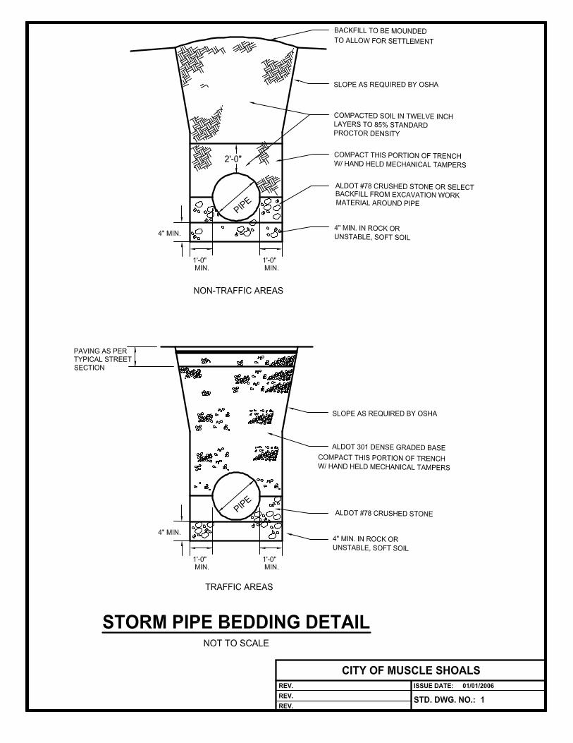
8.3 TRENCH EXCAVATION. Trench excavation or excavation for pipe linesshall consist of the excavation necessary for the construction of storm sewersand other pipe lines and all other appurtenant facilities therefor, includingmanholes, saddles, sand or crushed stone cushion, boxes, and pipeprotection as called for in the plans. It shall include clearing and grubbingwhere necessary, backfilling and tamping of pipe trenches and aroundstructures, and the disposal of waste material.
8.4 UNSUITABLE MATERIAL. When muck, quicksand, soft clay, swampy orother material unsuitable for foundations or subgrade are encountered whichextend below the limits of the excavation, such material shall be removed andreplaced with suitable materials.
8.5 LIMIT OF EXCAVATION. Pipe trenches shall not be excavated more than300 feet in advance of pipe laying. Temporary bridges or crosswalks shall beconstructed where required to maintain vehicular and pedestrian traffic.
8.6 PROTECTION. In all cases where materials are deposited along opentrenches shall be placed so that in the event of rain no damage will result tothe work and/or adjacent property.
8.7 STORING EXCAVATED MATERIAL. Material excavated is to be laidcompactly on the side of the trench and shall be kept trimmed up so as tooccasion the least practicable inconvenience to the public traffic and toneighboring residents.
8.8 DRAINAGE. Every drain, gutter, culvert or sewer for surface drainageencountered is to be kept open for temporary and permanent flow, or, ifnecessarily closed, other adequate provision is to be made.
8.9 TUNNELING. Pipe trenches for storm systems may be constructed bytunneling methods for relatively short distances for crossing major streets orhighways or railroads provided the manner of excavating, bracing, andbackfilling are approved by the City engineer.
8.10 RESERVED
8.11 RESERVED
8.12 RESERVED
8.13 RESERVED
8.14 RESERVED
8.15 RESERVED
8.16 MATERIALS
8.16.1 ROADWAY PIPE
8.16.1.1 REINFORCED CONCRETE PIPE. Piper shall conform to ASTMSpecifications Serial Designation C 76-57T, Class III
8.16.1.2 EXTRA STRENGTH REINFORCED PIPE. Extra strengthreinforced concrete pipe shall conform to ASTM SpecificationsSerial Designation C 76-57T Class IV.
8.16.2 SIDE DRAIN PIPE
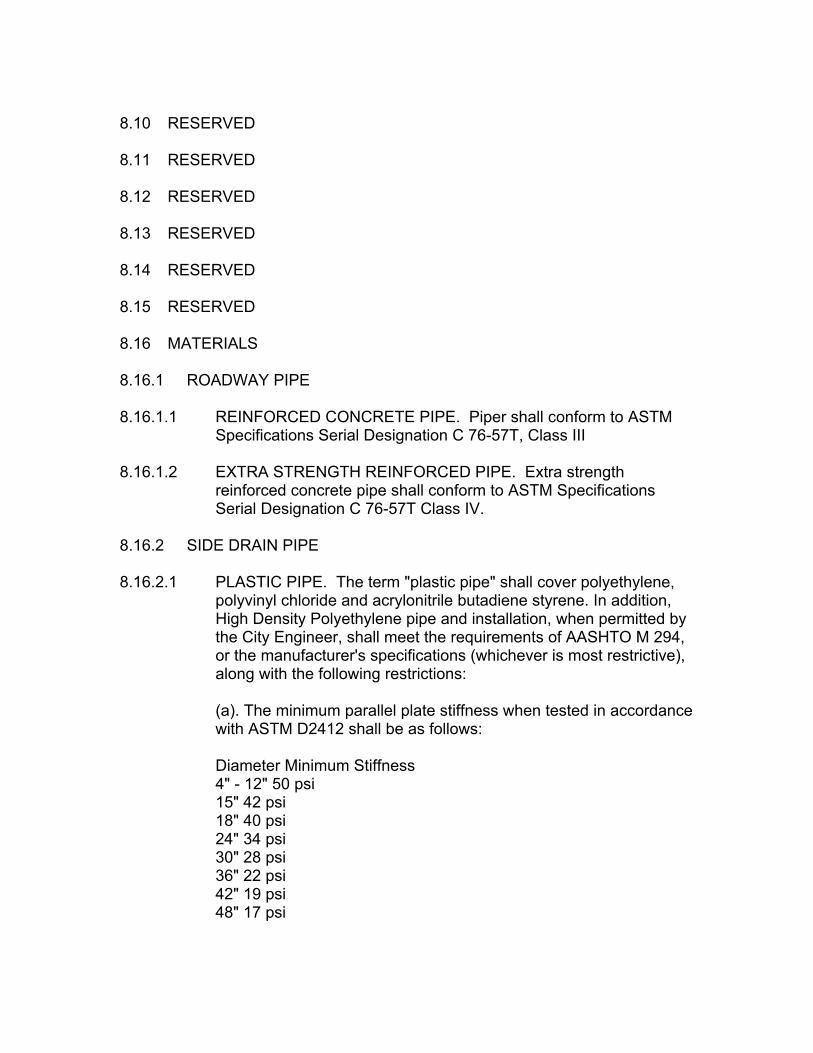
8.16.2.1 PLASTIC PIPE. The term "plastic pipe" shall cover polyethylene,polyvinyl chloride and acrylonitrile butadiene styrene. In addition,High Density Polyethylene pipe and installation, when permitted bythe City Engineer, shall meet the requirements of AASHTO M 294,or the manufacturer's specifications (whichever is most restrictive),along with the following restrictions:
(a). The minimum parallel plate stiffness when tested in accordancewith ASTM D2412 shall be as follows:
Diameter Minimum Stiffness4" - 12" 50 psi15" 42 psi18" 40 psi24" 34 psi30" 28 psi36" 22 psi42" 19 psi48" 17 psi

(b) Fill heights will be restricted to 20 feet maximum.
(c) Pipe cover shall be 12 inches minimum and shall be installedper ASTM D2321.
(d) Application and use of all plastic pipe shall be approved by theCity Engineer.
(e) All joints shall be soil-tight as per the manufacturersrecommendation.
(f) Pipe shall be used only in non-traffic areas as approved by theCity Engineer.
(g) In addition to these general requirements, pipes shall meet therequirements listed hereinafter for the type plastic used: PolyvinylChloride (PVC) pipe shall meet one of the following specifications:ASTM D-2241, F-789, D-1785, D-2665, D- 3034, D-2680, F-794, F-949, or F-679. Polyethylene (PE) pipe shall meet the requirementsof AASHTO M-294, Type C or S. When Type S pipe is used, theinner liner shall have a minimum thickness of 0.05 inches and befused to the outer shell. Acrylonitrile Butadiene Styrene (ABS) pipeshall meet the requirements of ASTM D-2751 or D-2680.
8.16.3 CORRUGATED METAL PIPE. Corrugated metal pipe (CMP), must bea spiral flow pipe with a manning coefficent equal to .012. The materialshall be aluminized steel type 2. It shall be installed according to themanufacturers recommendations for bedding and backfill. It may onlybe used in non-trafffic areas.
8.16.4 SIDE YARD DRAINAGE. Drainage conveyed within side yards inresidential districts shall be confined to pipe systems or shallow swales.Open ditches will be discouraged except in cases with very smallamounts of water. The City Building Department shall have theauthority to grant exceptions to this policy in cases where large volumesof stormwater must be conveyed through a side yard.
8.17 TESTING. All storm sewer pipe and materials used in its manufactureshall be tested and inspected by an approved commercial testing laboratoryprior to delivery to the site and all materials which fail to conform to thesespecifications shall be rejected. After delivery to the site any materials whichhave been damaged in transit or are otherwise unsuitable for use in the workshall be rejected and removed from the site. Certified copies in duplicate ofthe inspection and acceptance reports of the testing laboratory shall besupplied to the engineer prior to use of the materials. Each joint of pipe

delivered to the work shall be stamped or marked to indicate the testinglaboratory's acceptance or approval.
8.18 PIPE LAYING
8.18.1 GENERAL. Before storm pipe is placed in position in the trench thebottom and sides of the trench shall be carefully prepared and thenecessary bracing and sheeting installed. Each pipe shall be accuratelyplaced to the exact line and grade called for in the plans. Each piece ofpipe and special fitting shall be carefully inspected before it is placedand no defective pipe shall be laid in the trench. Pipe laying shallproceed upgrade, starting at the lower end of the grade and with thebells uphill. Trench bottoms found to be unsuitable for foundations afterpipe laying operations have been started shall be corrected and broughtto exact line and grade with compacted earth where necessary. Whenso directed by the engineer limestone aggregate or sand cushion shallbe installed to provide a satisfactory bearing surface.
8.18.2 Reserved
8.18.3 JOINTS. Joints shall be prepared in the manner specified below. Asthe work progresses the interior of all pipe in place shall be thoroughlycleaned. After each line of pipe has been laid it shall be carefullyinspected and all earth, trash, rags, and other foreign matter removedfrom the interior.
8.18.4 BACKFILLING. Backfilling of trenches shall be started immediatelyafter the pipe is in place and the joints completed and inspected andapproved.
8.19 JOINT CONSTRUCTION
8.19.1 CLEANING. The inside of all bells and the outside of all spigots shallbe wiped to remove all dirt, water or other foreign matter so that theirsurfaces are clean and dry when the pipes are joined.
8.19.2 MORTAR JOINTS. Joints and lift holes in concrete pipe shall be filledwith cement mortar. In all pipe sizes a bed of mortar shall be placed inthe lower quadrant of the bell before the spigot is inserted.
8.19.3 PROTECTION. After the joints have been completed they shall beinspected by the engineer before they are covered up. Any leaks ordefects discovered at any time after completion of the work shall berepaired immediately. All pipe in place shall be carefully protected fromdamage until the backfilling operations have been completed. Any pipe

which has been disturbed after the joint was completed shall be takenup, the joint cleaned and remade and the pipe relaid.
8.19.4 DEWATERING. Water shall not be allowed to run or stand in thetrench while pipe laying is in progress or before the joints arecompletely set or before the trench has been backfilled. The contractorshall not open up at any time more trench than his available pumpingfacilities are able to handle.
8.19.5 Reserved
8.19.6 SPECIAL CONSTRUCTION. Where the work requires special railroador roadway crossings or any other extraordinary conditions, or wherealternate types of construction are used that are not covered by thesespecifications, the materials and methods shall be as shown on theplans.
9. CURB INLETS, DROP INLETS, HEADWALLS
9.1.1 GENERAL. This section shall cover the construction of curb inlets anddrop inlets complete with the necessary metal frames and covers. Inletwalls may be "cast-in-place" concrete, brick masonry or, with the priorapproval of the City engineer, hollow core blocks filled with concreteafter laying. Drainage structures shall be constructed to the size, shapeand dimensions and at the locations shown on the plans.
9.2 MATERIALS
(a) Concrete material shall conform to the requirements of Section 21.
(b) Reinforcing steel shall conform to the requirements of Section 21
(c) Brick masonry materials shall be as follows:
(1) Brick shall conform to ASTM Designation C 32 Grade MA.
(2) Cement shall meet the requirements of ASTM Designation C 150 forPortland Cement
(3) Sand for mortar shall consist of hard, strong, durable, uncoatedmineral or rock particles, reasonably free from injurious amounts oforganic or other deleterious substances. Gradation shall be as follows:Percentage passing No. 8 No.50 No.10 by weight 100 15-40 0-100
(4) Water for mortar shall be obtained from the City water system. Anyother source of water shall be approved by the engineer.

(5) Curb inlet covers and frames and drop inlet gratings shall conform tothe requirements of Section 10 of this Specification.
9.3 EXCAVATION AND BACKFILL. Excavation and backfill shall be performedin accordance with the appropriate requirements as set forth under Section6.4 of this Specification.
9.4 CONCRETE MASONRY. All concrete masonry used in curb inlets and dropinlets shall be Class A and shall be constructed in accordance with theappropriate requirements set forth under section 21 of this Specification.
9.5 BRICK MASONRY. The foundation on which brick are to be laid shall be firmand dry. All brick shall be damp at the time of laying. Bricks shall be laid incourses in full, close joints of mortar. The courses shall be level in all places,except where otherwise directed. All exposed surfaces shall be smooth andclean. Broken or chipped bricks shall not be used in the exposed faces of themasonry. Joints shall be cleaned and pointed in a neat workmanlike mannerbefore the mortar sets.
9.6 MORTAR. The mortar shall be composed of one part of cement and twoparts of sand by volume, on the basis of dry sand, and sufficient water tomake a mortar of such consistency that it can be easily spread and handledwith a trowel. Mortar shall be mixed only in quantities required for immediateuse. Unless an approved mortar mixing machine is used, the sand andcement shall be mixed dry in a tight box until the mixture assumes a uniformcolor, after which water shall be added as the mixing continues until themortar attains the proper consistency. Mortar which is not used within 45minutes after water has been added shall be discarded. Retempering ofmortar will not be permitted.
9.7 Reserved.
9.8 PLACING CASTINGS. Castings shall be set in full mortar beds or otherwisesecured as shown on the plans. Castings shall be set to correct elevation.Castings set within the surface of paved streets or streets to be paved shallbe set even with the paved surface. (Castings need not be set level but mustbe graded to fit paving grade.)
9.9 CLEANING. All inlets shall be cleaned of all form material, excess mortar,silt, debris or foreign matter of any kind.
9.10 HEADWALLS
9.10.1 All materials furnished shall conform to the requirements of Section 21.
9.10.2 The concrete mix used for headwalls shall be ALDOT Class "A", Type 2unless otherwise authorized by the City engineer.
9.10.3 Foundation excavation shall be of the size and depth conforming to theoutline of the structure. Unsuitable foundation material below thenormal design elevation shall be removed as directed by the engineer.Where rock, gravelly soil, hardpan or other unsuitable material isencountered, it shall be removed as ordered by the engineer for a depthof at least 6 inches below the designated grade.
9.10.4 Foundation backfill shall be deposited uniformly for the full width of theexcavation in layers not exceeding 6 inches in depth with each layercompacted.
9.10.5 Construction, forming, placing, etc. of headwalls shall be in accordancewith the appropriate requirements of ALDOT 501.03.
9.10.6 All surfaces will receive a Class 1 surface finish and all exposedsurfaces will receive a Class 2 surface finish. In order to permit propersurface finishing, forms may be removed as soon as the concrete hasset sufficiently that form removal will not damage the green concrete,but in no case less than 12 hours after completion of the placing.Immediately after pouring is completed, surfaces not covered by formsshall be covered with one of the curing materials specified in ALDOTSection 830. Finishing shall begin immediately after removal of theforms, and curing continued for at least 72 hours after finishing.
9.10.7 The finished concrete shall be within reasonably close conformity to theline, grades and dimensions shown on the plans, and free fromobjectionable cavities or projections.
10. CURB INLET COVERS AND FRAMES
10.1 DESCRIPTION. Curb inlet covers and frames shall be gray iron castings.The castings shall be boldly filleted at angles. They shall be true to pattern inform and dimension and shall be free from cracks, pits, blowholes or otherdefects.
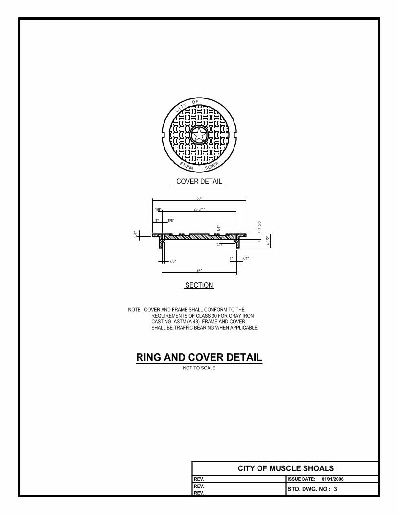
10.2 MATERIAL. All frames, covers and gratings shall conform to therequirements of Class No. 20 for Gray Iron Castings, ASTM Designation A48.

10.3 CLEANING. All castings shall be sand blasted or otherwise effectivelycleaned of scale and sand so as to present a smooth, clean and uniformsurface.
10.4 IDENTIFICATION. All frames and covers shall be identified with the nameof the foundry and the date of casting. Identification shall be in raised orindented letters in the surface of the casting. Identification on lids and framesshall be on the underside.
10.5 GUARANTEE. The manufacturer shall guarantee all castings againstdefects in material or workmanship for a period of 18 months after date ofplacement.
11. STREET AND DRAINAGE EXCAVATION
11.1 CONSTRUCTION METHODS
11.1.1 All necessary clearing and grubbing shall be done in proper sequencewith excavation and construction. All excavation shall be conducted insuch manner and by such methods and equipment as will insureagainst removing or loosening any material outside of the street right-ofway.
11.1.1.1 Gutters, ditches, channels and channel changes shall beconstructed only when and as shown on the plans or when and asdirected by the engineer to lines, grades and cross- sectionsestablished by him, in proper sequence with other work and whenand as he directs. Excavation for channels shall preferably bemade before the excavation for structures is started. Whennecessary in order to provide proper gradient of flow line, theengineer may direct that channels be extended beyond the limits ofthe street.
11.1.1.2 Changes of direction in open channels shall have the channelprotected from erosion on the bottom and both banks for asufficient distance upstream and downstream of the directionalchange. The City Engineer may require calculations to verify theadequacy of channel protection in these areas.
11.1.1.3 Intersections of open channels shall be protected from erosion andscouring by placing concrete on the bottom and both banks of thechannels upstream and downstream for a sufficient distance toensure that the channel is protection from erosion.

11.1.1.4 Headwalls shall be constructed at all points where undergrounddrain pipes exit into open channels and where open channels enterinto sub-surface drains.
11.1.2 Intersecting ditches or dikes shall be constructed as soon as practicableafter clearing and grubbing operations are completed and prior toexcavating the cuts.
11.1.3 All suitable materials removed from the excavation shall be used as faras practicable in the formation of the embankment, subgrade, basecourse, shoulders, slopes, bedding and backfill or for such otherpurposes and at such other places as directed. No excavated materialshall be discarded without written permission and when such material isto be discarded it shall be disposed of as prescribed in Section 6.8.1.
11.1.4 The materials excavated from channels, channel changes, waterwaysand ditches shall be utilized in the construction of embankments, thewidening and sloping of embankment slopes, the backfilling ofabandoned ditches and channels or otherwise disposed of as directedby the engineer. No excavated material shall be left in unsightly pilesbut shall be spread in uniform layers, neatly leveled and shaped. Nowaste or surplus excavation from a ditch or channel shall be depositedor left within 3 feet of the edge of the ditch or channel.
11.1.5 All rock or boulders encountered in the roadway shall be excavated tothe lateral limits shown on the plans and to a depth of at least 9 inchesbelow subgrade, and the resulting space backfilled to proper grade withsuitable material as directed by the engineer. In blasting rock, areasonably uniform face shall be left. The engineer, the City engineer orthe City fire marshal shall have authority to require cessation of anymethod of blasting which leads to overshooting or is dangerous to thepublic or destructive to property or to natural features.
11.1.6 Attention is directed to the possible existence of pipe lines or otherpublic utilities which may be buried within the limits of the work oradjacent thereto, and which may or may not be shown on the plans.The contractor shall be responsible for and take all necessaryprecautions to protect and preserve any and all existing drains, sewers,surface drains, pipes, conduits and other underground structure or partsthereof which may be affected by his operations on the work and which,in the opinion of the engineer, may properly be continued in use withoutany changes. The contractor shall assume full responsibility forreimbursing the owners for any damage or injury to property orinterference with other services.

11.1.7 The contractor shall repair, replace, relocate, extend, reconstruct ormake any other changes in any tile drain, sewer or other subsurfacedrain, or water, gas line, or other utility line encountered in theprosecution of the work.
11.1.8 Grading operations shall not be performed to the prejudice of the workof blading and maintaining the street bed and subgrade and basecourse. The engineer or the City engineer shall have full authority toorder the suspension of other contract operations pending the adequateand proper performance of such maintenance work.
11.1.8.1 While the excavation is being done and until the work is finallyaccepted, the work shall be protected and the loss of material fromthe street by erosion shall be held to a minimum.
11.2 SOD. Where sod is disturbed in grading lawns between curb and walks,in terracing property, in setting or resetting curb, or in other work it shall becarefully removed, relaid and watered. New sod will be laid where the old soddies before the acceptance of the work. Sod destroyed by piling of materialsor tools shall be replaced with new sod.
11.3 PIPES. The City and those under contract with or having franchise rightsfrom the City shall be permitted to construct or lay sewers, water or gaspipes, and other conduits in those portions of the street or easements wherethere is a fill before the filling is commenced. The remainder of the street shallbe brought to subgrade as soon as possible and the above mentioned partiesgiven an opportunity to lay such pipes or other conduits before the basecourse is laid. On completion of the laying of pipes in any block or part of ablock the grading shall be completed as soon as possible. All partiesexcavating in streets shall backfill cuts in accordance with Paragraph 6.6.2 ofthis Specification.
11.3.1 Utilities under streets or in easements adjoining streets shall beinstalled in strict accordance with Section 18 of this Specification.
11.4 SIDEWALK AND LAWN. The sidewalk and lawn space shall be graded tothe lines given by the engineer. Where dirt is removed for curb and gutter andis thrown in the street or in the sidewalk space or on the sidewalk, thecontractor will remove it therefrom prior to the close of work that day.
11.5 MONUMENTS. Engineer's monuments, bench marks, stakes and allmeter boxes, manhole rims and covers and other castings will be preserved.

12. EMBANKMENT
12.1 DESCRIPTION. This section shall cover the placing in embankmentssuitable material excavated under other sections of this Specification inconformity with the lines, grades and cross- sections shown on the plans.Embankment construction shall include the preparation of the area uponwhich the embankment is to be constructed, the preparation and selection ofmaterials, the formation, compaction and stability of the embankment and thedisposal of surplus and unsuitable material.
12.2 MATERIALS. Only suitable materials shall be used in the construction ofembankments and backfills. No brush, roots (larger than 1" in diameter),rubbish, limbs, logs, stumps, heavy vegetation or other unsuitable materialshall be incorporated or placed in the embankments or backfill. All unsuitablematerial shall be disposed of. Grading operations in street and drainageexcavation shall be so conducted that all suitable material shall be usedwhere required for the formation of embankments, subgrade, shoulders,approaches, intersections, and for backfilling around structures. The workshall be done in such a manner and sequence that the most suitable soil shallbe reserved for topping as far as practicable.
12.3 EQUIPMENT
12.3.1 The rolling equipment shall consist of adequate sheepsfoot tampingrollers or other mechanical compacting equipment and, if required,pneumatic tired rollers of an approved design.
12.3.2 A blade grader and/or bulldozer shall be kept on the work and shall beused to keep each lift of the fill machined at all times while theembankment is being constructed and tamped.
12.4 PREPARATION
12.4.1 Before beginning embankment construction, clearing and grubbing shallbe performed as provided in Section 5 of this Specification.
12.4.2 Natural Ground Slopes and Old Embankments
12.4.2.1 Where embankments occur adjacent to natural ground whichslopes more than 20 degrees from horizontal, such slopes shall be:(a) removed of all topsoil (b) plowed or loosened to a depth of atleast 6 inches before backfilling is commenced and (c) the topsoilremoved, stored onsite or placed under embankment slopes
12.4.2.2 In cases where widening of embankments is necessary, the slopeof the old embankment shall be stepped and plowed before placing
additional material. The embankment shall be placed to a sufficientheight and width so that after full shrinkage, settlement andsubsidence, and sloughing of the side slopes, the fills will be at therequired grade and have the specified cross-section at all points.When the widening on either side of the center line is less than 6feet measured horizontally by cross-sections, stepping, parallellayer construction and density as specified herein will be requiredonly in the next 2 feet below subgrade elevation.
12.4.2.3 When the embankment is to be superimposed on old pavements orpavements having concrete bases, (so-called rigid types), theprocedure shall be as follows:
(a) If the depth of new embankment (exclusive of new pavingmaterial and base course) is less than 1 foot, the old pavementshall be removed and disposed of.
(b) If the depth of the new embankment (exclusive of new materialand base course) exceeds 1 foot but is less than 3 feet, the oldpavement shall be broken with a drop hammer of suitable weightinto pieces less than 2 square feet in area, at the same timepounding or forcing such pieces into the subgrade. Broken piecesshall be subsequently covered with sand in an amount sufficient tofill all cracks
(c) If the depth of embankment (exclusive of new paving materialand base course) is 3 feet or over, the old pavement shall not bedisturbed.
(d) When embankment is to be superimposed upon any other typeof pavement or surface the existing pavement or roadway surfaceshall, (regardless of the depth of the embankment to be placedthereon), be scarified to such a degree as will provide ample bondbetween old and new material.
12.5 FORMATION
12.5.1 The material shall be deposited and spread in successive uniformlayers of not more than 8 inches in depth loose measurement for the fullwidth of the required cross- section, and shall be kept level or parallel tothe finished subgrade by the use of blade graders, except that aroundbridge ends and structures, leveling shall be done with bulldozers andhand methods. Each layer of embankment shall be rolled andcompacted to specified density hereinafter provided. Embankments andslopes shall be finished true and straight, in conformity with the lines

and grades of slope set by the engineer, and all slopes, whether old ornew, shall be maintained with true and even surfaces.
12.5.2 Unless specific preparatory treatment is provided, where low swampyground will not support the vehicles, the thickness of the bottom layermay be increased to a depth not greater than that required to supportthe said vehicles while placing subsequent layers. Subsequent layersshall be constructed and compacted as provided above.
12.5.3 Where embankments are being constructed predominantly of rock, thestones, broken rock and boulders shall be placed in layers and all voidsshall be completely filled with suitable earthy materials and thoroughlycompacted. No layer of such rocky material shall be placed within 9inches of the subgrade or finished earth shoulders. Where rockexcavation is used in embankments, all excavation, of whatever class inthe vicinity, shall be managed so that all coarse rock will be placed andembedded in the embankment before any fine rock and earth shall beused.
12.5.4 Over, under and around pipes, culverts, arches, bridges and otherstructures shall be of selected embankment materials placed andtamped and compacted in a manner and by methods that will avoidunbalanced loading, and that will not cause movement or place unduestrain on any structure. The embankments that are placed against orimmediately adjacent to bridge abutments, retaining or wing walls, openend bents and culverts shall be built in horizontal layers not exceeding6 inches loose and must be compacted by mechanical tamping and/orrolling. This method of building embankments will be required for suchdistance from these structures until rollers can effectively tampembankments.
12.5.5 Suitable coarse rock will be used in constructing the stream side of allembankments which are adjacent to or parallel to streams. Materialsdeposited in any stream channel that in any way whatsoever obstructsor impairs the flow of the stream or endangers a roadway or streambank shall be removed as directed by the engineer or the City engineer.Side ditches or gutters emptying from cuts to embankments orotherwise shall be so constructed as to avoid damage to embankmentsby erosion.
12.6 EMBANKMENT COMPACTION
12.6.1 Embankments shall be rolled as stipulated herein unless otherwisespecified by the engineer. The density of each layer (except the top 6"or subgrade layer) shall be not less than 95% of the relative maximumdensity as determined by AASHTO compaction test T99. The top 6" or

subgrade layer shall be as provided by Section 13 of this Specification.Each layer of embankment material which does not contain sufficientmoisture to compact thoroughly shall be sprinkled and mixed with wateras directed by the engineer. Watering may also be done before materialis removed from cuts or pits. Material containing excess moisture shallbe allowed to dry out to the proper consistency before compacting isattempted. Successive layers shall not be placed until the layer underconstruction has been compacted.
12.6.2 Very Sandy Material When the embankment material is of a very sandynature and it is impractical to compact it with rollers, the material shallbe spread in 6" maximum loose layers and each layer watered, thenrolled with the tracks or treads of a 10-ton tractor which shall cover theentire surface of the layer.
12.7 SPECIAL SLOPE PROTECTION
12.7.1 The work covered by this section consists of furnishing all materials,equipment and labor and performing all necessary operations inconnection with the installation of rip-rap or other special slopeprotection, as called for in the plans.
12.7.2 Areas to receive rip-rap or special slope protection materials shall begraded to the lines and slopes shown on the plans, or as directed bythe City engineer. Any loose material shall be compacted by the use ofhand or mechanical tampers.
12.7.3 Stone for rip-rap shall be of the size and weight designated on theplans. In addition, the stone shall be durable and of a suitable quality toinsure permanence in the structure in which it is to be used.
12.7.4 Just prior to placing rip-rap or other slope protection material, thecontractor shall install a nonwoven plastic filter fabric. The filter fabricshall be approved by the City engineer for installation and shall then beinstalled in strict accordance with the manufacturer's specifications forinstallation and use. Only then, and after approval by the City engineer,shall the slope protection material be installed on the filter fabric.Attention is called to the standards contained in Section 6.8.4 above.
13. SUBGRADE
13.1 DESCRIPTION The subgrade shall be considered as that portion of thestreet bed on which the base course or curb and gutter is to be placed. Afterthe earth work is substantially completed and after all drains have been laidand after all utilities under the pavement are in place, the subgrade shall bebrought to the lines, grades and cross-sections shown on the plans, and

finished in accordance with the plans. Subgrade material shall meet therequirements of Soil Classifications A-1, A-2, A-3, or A-4 as determined byAASHTO specification M-145 within the following limitations:
A. materials in the A- I or A-3 classification will not require consideration of aCBR value.
B. materials in the A-2 or A-4 classification shall have a CBR value of notless than 10.
C. Materials of the cherty or float gravel type which have a minimum 500/ometal retained on the number 8 sieve, 100% passing the 4" sieve, and CBRvalue of at least 25 will not be required to conform to the soil classificationnoted above. Certification by the developers geotechnical engineer shall besubmitted to the City addressing the subgrade material.
D. Where materials do not meet the above requirements a geotechnicalreport should be submitted by the developer’s geotechnical engineer as tothe proposed subgrade design.
13.2 PREPARING SUBGRADE
13.2.1 The subgrade shall be so constructed that it will have, as nearly aspracticable, uniform density throughout. No base course, surfacing orpavement shall be placed on the subgrade until specified density isobtained, and until the subgrade conforms to the grade and cross-section shown on the plans and until the subgrade has been checkedand approved.
13.2.2 Before placing any material on a subgrade, it shall be firm andcompacted and shall have passed an inspection for compaction inaccordance with Section 13.2.4 of this Specification. When necessary,the subgrade shall be sprinkled. The subgrade shall be constructed sothat it will be uniform in texture and have as nearly as possible uniformdensity throughout. Subgrade material shall be placed in maximum 8"lifts. No base course or sub-base course shall be placed on thesubgrade until the specified density is obtained, and until the subgradeconforms to the lines, grades and cross-sections shown on the plans.The density of the top 6 inches of subgrade shall be not less than 100%of the maximum density as determined by AASHTO Compaction test T-99. In no case shall any roadbed material, base course, pavement orsurface course be placed on a frozen, muddy or excessively dirtysubgrade. Storing or stockpiling of material on the subgrade will not bepermitted.

13.2.3 All boulders, brick, concrete or similar solid items or ledge rockappearing in the earth excavation shall be removed or broken off to adepth of not less than 9 inches below the subgrade. The depressionsleft by such excavation shall be filled with suitable material. All soft andunstable material and other portions of the subgrade that will notcompact readily or serve the intended purpose shall be removed. Theresulting areas and all other low sections, holes or depressions shall bebrought to profile grade with satisfactory selected material and theentire subgrade shaped to line, grade and cross-section. The entiresubgrade, both in cut and in fill, shall be compacted to a density of notless than I 00% of the maximum density in the top 6" layer as requiredin section 13.2.2 above and 95% of the maximum density below 6" indepth as determined by AASHTO Compaction Test T-99. Moisturecontent at the time of the in-place density test shall be within + or - 2%of the optimum moisture content established during the control densitytest.
13.2.4 Density test shall be performed at a minimum of 300' intervals or atleast once on short streets less than 300' in length. Developer shallprovide the City with results of in-place density test. Also the subgradeshall be proof rolled with a double axle truck with a minimum net load ofnot less than 20 tons to check for unstable areas. Any areas found tobe unstable will be repaired prior to the placement of curbs or base.
13.2.5 Particular attention shall be paid to compaction around manholes, oversewer lines and laterals, and over other utility and drainage crossings.Where deemed necessary by the engineer or the City engineer or hisrepresentative, hand tamping shall be required.
13.2.6 Where the plans indicate that a base course, surface course orpavement is to be placed, any requirements as to subgrade containedin the specifications for such base course, surface course or pavementshall be performed accordingly. Subgrade proof rolling shall beperformed with a double axle truck with a minimum net load of 20 tons.
13.2.7 After proof rolling, the subgrade shall be checked and all portions not attrue elevation shall be corrected and compacted to correct elevation.The subgrade shall be tested after rolling and sufficient material shallbe added or removed to bring all portions of the subgrade to properelevation.
13.2.8 All intersecting public streets or highways shall be graded as shown onthe plans, and acceptable materials used on the surface so that acommodious, smooth riding and satisfactory intersection shall beproduced. Grading of the subgrade shall be conducted so that berms of

earth or other material do not prevent immediate drainage of water tothe side ditches or gutters. Gutters, ditches and drains along subgradeshall be so maintained at all times as to drain effectively. When haulingresults in ruts or other objectionable irregularities, the subgrade shall becompacted to required density before the surfacing is placed.
13.3 PROTECTION AND MAINTENANCE OF SUBGRADE. The subgradeshall be maintained free from ruts and other depressions, in a smooth andcompacted condition true to lines and grades and to density requirementsuntil the base, surfacing or pavement is placed.
14. 14 DENSE GRADED AGGREGATE BASE COURSE
14.1 DESCRIPTION. This item shall consist of dense graded crushedlimestone base course composed of one or more well controlled aggregatesizes, water mixed with and without calcium chloride, as directed, placed andcompacted in accordance with these Specifications and in conformity withlines, grades and cross- sections shown on the plans. All material shallconform to the requirements set forth in Section 14.1.2 of this Specification.
14.1.1 Coarse Aggregate.
14.1.1.1 Coarse aggregate shall consist of crushed limestone, free fromadherent coatings and conforming to the requirements of thisSpecification.
14.1.1.2 Deleterious Substances in coarse aggregates shall not exceed thefollowing limits:
1. Soft fragments ................................. 6.0%2. Coal and lignite ............................... 0.25% 3 Clay lumps ..................................... 0.25% 4. Material passing a #200 sieve .................. 2.0% 5. Thin or elongated pieces (Length greater than 5 times averagethickness) ..................... 10.0% 6. Other local deleterious substances ............. 2.0% 7. Total of Nos. 1, 2, 3, and 6 above............ 8.25%
14.1.2 Crushed Stone.
14.1.2.1 Crushed stone shall consist of clean, tough, durable fragments ofrock conforming to the class and gradation specified.
14.1.2.2 Crushed stone shall meet the following requirements for therespective physical tests:

TEST LIMITS FOR TYPE CONSTRUCTION Concrete Bituminous OtherPercent wear, Los Angeles Test(AASHTO T-96) 50 Max 48 Max 60 Max
Percent sound, Soundness Test(AASHTO T-104) 90 Min 90 Min 90 Min
14.2 Gradation.
14.2.1 Coarse aggregate shall be graded within the limits specified and thesize or sizes designated shall conform to the limits shown in the CoarseAggregate Gradation Table provided in ALDOT Section 801 Subarticle801.11(d).
14.2.2 The dense graded mixture as processed shall contain moisture within2% of the optimum moisture content of the aggregates, and theaggregates shall be blended together in such a manner that if sampledand tested, it shall meet the following gradation without abrupt variation:
TOTAL PASSING PERCENTAGE BY WEIGHT2" sieve . . . . . . . . . . . . . . . 1001.5” sieve. . . . . . . . . . . . . .90-1001" sieve . . . . . . . . . . . . . . . 75-981/2" sieve . . . . . . . . . . .. . . 60-85No. 4 sieve . . . . . . . . . . . . . 40-65No. 8 sieve . . . . . . . . . . . . . .28-54No. 16 sieve . . . . . . . . . . . . 19-42No. 50 sieve . . . . . . . . . . . . 9-27No. 200 sieve . . . . . . . . . . . . 4-18
14.3 CONSTRUCTION METHODS.
14.3.1 The roadbed must be in an approved condition before placement of anybase or subase will be permitted. Approval shall be based onsatisfactorily completion of the roadbed in accordance with therequirements of Section 13.
14.3.2 In general, it shall be the Contractor's responsibility to select andfurnish the proper size and amount of equipment that will produce anddeliver to the roadbed, mix, spread, shape and compact the base
material.
14.4 MIXING BASE COURSE AGGREGATES. Premixing of the materials forthe base course will be required. They shall be mixed by approved pug mixequipment, either at point of use or at a central mixing plant. Water shall beadded during the mixing operation in an amount to make the total moisturecontent of the mixture not less than 5% by weight, and sufficient to make aworkable mixture. At no time during the mixing operation shall the moisturecontent exceed the designated optimum by more than 2%. In case thematerial becomes too dry before compaction, water shall be added. For thetop layer only, calcium chloride may be added during the mixing operation atthe rate of 10 pounds of flakes per loose cubic yard of mixture.
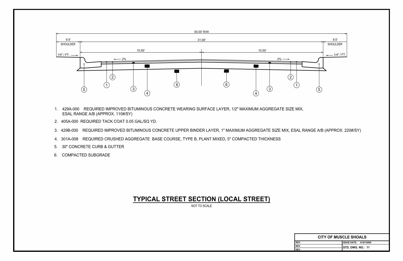
14.5 PLACING MATERIAL. In mixing, handling and placing the base material,care shall be taken to prevent segregation. The base course material shall beplaced in not more than 6 inch compacted layers on an accepted subbase orsubgrade. The minimum nominal thickness of the base material in place shallbe 5", unless otherwise approved by the City Engineer. Reference is made tothe typical sections for local and minor collector streets in the Appendix.
14.6 COMPACTING AND MACHINING. The surface of the base coursematerial shall be immediately and continuously machined with motor graders,maintaining the required section and compacted with steel wheel rollers. Thebase course shall be compacted until it reaches 100% proctor density. Steelwheel rolling shall extend beyond the curb line where curb and gutter is to beplaced on the base material, and to the curb and gutter where the curb isplaced on subgrade. When compaction is complete, the base course shall besmooth, hard, dense, unyielding and well bonded.
14.7 INSPECTION. Density test shall be performed at a minimum of 300'intervals or at least once on short streets less than 300' in length. Developershall provide the City with results of in-place density test. Also the subgradeshall be proof rolled with a double axle truck with a minimum net load of notless than 20 tons to check for unstable areas. Any areas found to be unstablewill be repaired prior to the placement of curbs or base.
14.8 MAINTENANCE. The entire roadway shall be maintained, and areasfound defective shall be corrected and, if necessary, the subgrade and baseshall be replaced. Maintenance shall include maintaining the shoulders(where they exist) to a uniform grade and slope, keeping all drainage ditchesfree from loose earth or other objectionable material, and keeping theroadbed drained at all times until the surface coat is applied. The base shallbe machined as often as necessary to maintain it smooth and to grade andcross-section until the wearing surface is applied. The maximum speed oftrucks when hauling or traveling any part of the base course under

construction shall be 20 miles per hour.
15. CURB AND GUTTER
15.1 GENERAL. This section shall cover the work of constructing portlandcement concrete combination curb and gutter.
15.2 MATERIALS. All materials shall conform to the requirements of ALDOTSpecifications Section 623.02. Concrete shall conform to the requirements ofSection 21 of this Specification.
15.3 CONSTRUCTION REQUIREMENTS
15.3.1 Concrete mixes shall be as provided by Section 21 of this Specification,with a Class A mix being used with standard forms and a Class A mix,modified as deemed necessary by the engineer to fit the type curbingmachine being used.
15.3.2 Foundation shall be constructed or excavated to the required depthbelow the finished surface in accordance with the cross-section shownon the plans. All soft or other unsuitable material shall be removed andreplaced with suitable material in layers not to exceed 4 inchescompacted. The foundation shall be proof rolled with a two-axle truckwith a minimum 20 ton net load.
15.4 FORMS
15.4.1 The contractor shall use standard type metal forms as notedhereinafter or an approved automatic extrusion type curb-and-guttermachine.
15.4.2 At each street or driveway crossing where there is to be sidewalk, thecurb shall be modified to provide a ramp from the sidewalk to the street.
15.4.3 Combination curb and gutter shall be 30 inches wide at the base. ThePlanning Commission may allow other sizes an types of curbs based onthe individual situations.
15.4.4 Standard forms shall be metal, except for radial sections. They shall bestraight and free from warps and of sufficient strength, when staked, tohold the concrete true to line and grade without distortion. They shallprovide the approved typical section and depth of the section shown onthe plans. Radial or curved forms may be of flexible metal, or a wood

form of approved design may be used. Bent or damaged forms shall notbe used. All forms shall be securely staked, braced and held together tothe line and grade established and shall be kept sufficiently tight toprevent leakage of mortar. All forms shall be cleaned and oiled with asuitable oil immediately before concrete is placed against them.
15.4.5 Machine formed Any automatic extrusion type curb-and-gutter machinemust produce a section conforming to the dimensions, cross-section,lines and grades shown on the plans within the tolerances provided inParagraph 15.8(b) of this Specification for formed curb and gutter. Allcurb and gutter shall be placed in one operation to the depth of cross-section shown on the plans. The use of a two stage operation will notbe permitted.
15.5 SECTIONS. Combination curb and gutter shall be constructed in sectionsof the lengths shown on the plans. The length of sections may be reducedwhen necessary to form closure. Sections shall be formed with expansionjoints not more than 60 feet apart, and with contraction joints spaced at 10foot intervals.
15.6 MATERIAL HANDLING, PROPORTIONING AND MIXING. The handling,storing, proportioning and mixing of concrete shall conform to therequirements of Section 21.
15.7 JOINTS.
15.7.1 All expansion, contraction and construction joints shall be constructedas shown on the plans and in accordance with the requirements ofSection 21 of this Specification. If not shown on the plans, joints shallbe placed as follows:
15.7.2 Expansion joints shall be placed in curb and gutter to match those inconcrete pavement where the two are adjacent, but in no instance shallthere be more than 60 feet between expansion joints.
15.7.3 Expansion joints 3/4 inch wide shall be placed where curb and gutterterminates against rigid objects.
15.7.4 Expansion joint filler and sealer shall meet the requirements of Section21 of this Specification. Expansion joint filler shall extend from thebottom of the curb and gutter to within 1 inch of the top and the sealershall be 3/4 inch thick and shall be recessed 1/4 inch from the top.

15.7.5 Contraction joints shall be placed in curb- and-gutter to match those inconcrete paving where the two are adjacent, but in no instance shallthere be more than 10 feet between joints. Contraction joints shall besawed or otherwise cut 2 inches deep by 1/8 inch wide and shall extend2 inches below the pavement surface.
15.8 PLACING AND FINISHING - STANDARD METHOD
15.8.1 The subgrade and forms shall be checked and approved just prior toplacing concrete against them. All debris or other foreign material shallhave been removed from the space to be occupied by the concrete.The subgrade shall be moist but not wet or muddy. The concrete shallbe placed in the forms and shall be tamped, spaded or vibratedsufficiently to produce a dense homogeneous mass and to bring themortar to the surface. Particular attention shall be given to spading andplacing the concrete along and against the surface of the forms toprevent honeycombing and to secure a smooth, uniform surface.
15.8.2 When the forms are filled, the concrete shall be struck off with atemplate cut to the curb edge design. The exposed concrete surfaceshall then be finished smooth with a wooden float in a manner that willcompact the mass and produce a true, even top surface. Plastering withmortar to build up or finish will not be permitted. The surface of thegutter and the top and face of the curb will be checked with a 10 footstraightedge and any irregularities more than 1/4 inch in 10 feet shall becorrected. The alignment and grade shall not at any point vary morethan 1/2 inch from that established by the elevation control stakes.Excessive troweling with a steel trowel will not be permitted. A texturedfinish shall be provided on the exposed surface just before the concretebecomes non-plastic by the use of a burlap or cotton fabric drag, brushor broom which will produce a uniform gritty texture along the length ofthe curb and gutter. The upper edges of curb shall be rounded with anedging tool to the radius shown on the plans. Joint templates shall beset during the placing of the concrete and allowed to remain in placeuntil the concrete has set sufficiently to hold its shape, but shall beremoved while the forms are still in place. The forms shall be left inplace until concrete has set sufficiently so that they can be removedwithout damage to the work but, unless otherwise directed, they shallbe removed within 24 hours after the concrete has been placed.Immediately after removal of the forms, any minor defects shall berepaired.

15.9 PLACING AND FINISHING- MACHINE METHOD. Placing and finishingmachine laid curb and gutter shall be in accordance with Paragraph 15.4 ofthis Specification except that fixed forms are not required.
15.10 CURING AND PROTECTION. Immediately after the finishing operation iscompleted, the concrete shall be cured as provided in Section 21.
15.11 BACKFILLING. After the concrete has set sufficiently, spaces along thefront and back sides of the curb and gutter shall be backfilled to the requiredelevation with suitable material which shall be compacted by tamping withapproved metal tamps or mechanical tamps in layers not more than 4 inchesthick until firm and solid.
16. ASPHALT BITUMINOUS MATERIAL PLANT MIX
16.1 DESCRIPTION. This Section pertains to a two step plant mix bituminousapplication with the mix prepared at a stationary plant.
16.2 BITUMINOUS CONCRETE BINDER LAYER
16.2.1 The work covered by this Section shall consist of a hot bituminous plantmixed binder layer placed on a prepared surface and to be covered bya bituminous wearing surface in accordance with these Specificationsand in reasonable close conformity with the lines, grades, and typicalcross-section shown on the plans and required by these Specifications.
16.2.2 The materials furnished shall conform to the requirements of ALDOTSection 429.
16.2.3 For a Local Street, the binder shall consist of a 2” compacted hotbituminous plant mix binder layer, according to ALDOT Section 429.Binder layer shall be installed according to ALDOT Section 410 andshall meet the density requirements of ALDOT Section 306. For aMinor Collector Street, the binder shall consist of a 2.5" compacted hotbituminous plant mix binder layer, according to ALDOT Section 429.Binder layer shall be installed according to ALDOT Section 410 andshall meet the density requirements of ALDOT Section 306.
16.3 BITUMINOUS CONCRETE WEARING SURFACE.
16.3.1 The work covered by this Section shall consist of constructing a hotbituminous concrete wearing surface on a prepared surface inreasonable close conformity with the lines, grades, and typical cross-section shown on the plans and required by these Specifications.

16.3.2 The materials furnished shall conform to the requirements of ALDOTSection 410 and 429.
16.3.3 All mixes in this Section, regardless of the type aggregate used, willrequire the use of an anti-strip agent. All gravel aggregates shall bewashed prior to crushing. All mixes in this Section shall be designed onthe fine side of the Maximum Density Curve.
16.3.4 Aggregates shall meet the requirements of ALDOT Sections 801 and802, with particular attention directed to Article 802.04 and thefollowing:
16.3.5 Coarse aggregates for an actual wearing surface shall be limited tosiliceous aggregates such as gravel, granite, slag, sandstone, or acombination of the proper sizes of these materials that will produce amix within the required gradation limits. Carbonate stone, such aslimestone, dolomite or aggregates which tend to polish under traffic willbe permitted only in underlying layers, shoulder paving, or widening.
16.3.6 All coarse aggregate shall be crushed aggregate meeting therequirements of ALDOT Section 801.
16.3.7 For a Local Street, the wearing surface shall consist of a 1.0"compacted hot bituminous concrete wearing surface according toALDOT Section 429. The wearing surface course shall be installedaccording to ALDOT Section 410 and shall meet the densityrequirements of ALDOT Section 306. For Minor Collector Street, thewearing surface shall consist of a 1. 5" compacted hot bituminousconcrete wearing surface according to ALDOT Section 429.
16.3.8 Construction requirements shall be as specified in ALDOT Articles410.03 through 410.07. In the event the subgrade material andcompaction standards cannot meet the standards specified, the designengineer shall present an alternate design for the road section. Thisdesign shall meet the following minimum traffic requirements of LocalStreet: 2000 vpd Minor Collector Street: 2500 vpd The design shall bein accordance with the AASHTO Method of Flexible Pavement Design,Caltrans Method of Flexible Pavement Design, or a method approvedby the City Engineer. In no case, however, shall the pavement sectionused be less than that required in these specifications.
17. CONCRETE SIDEWALKS
17.1 RAMPS. Where sidewalks intersect cross streets or driveways, rampsshall be constructed from the sidewalk to the street or driveway. Ramps shall

meet ADA standards for maximum slope.
17.2 MATERIALS. All materials furnished for use shall comply with therequirements of ALDOT Section 618.02 and the following: Concrete shallmeet the requirements for a Class A, Type 2 mix as provided in Section 21 ofthis Specification. Reinforcing steel, if required, shall meet the requirementsof Section 21 of this Specification
17.3 CONSTRUCTION REQUIREMENTS.
17.3.1 The contractor may use forms or, upon approval of the engineer, anapproved automatic extrusion type paving machine.
17.3.2 Forms shall be of wood or metal and shall be sufficiently staked to holdthem true to line and grade while concrete is being deposited againstthem. The depth of the forms shall equal the depth of the sidewalk.Adequate means shall be provided for securely fastening the ends offorms together.
17.3.3 Any automatic extrusion machine considered must be demonstrated toproduce a consolidated concrete section conforming to the dimensions,cross-section, line and grades shown on the plans.
17.4 SUBGRADE. All soft or otherwise unsuitable material in the subgradeshall be removed and replaced with suitable material. All fills and fillingmaterial shall be placed and compacted with an approved roller or handtamped in layers not exceeding 6 inches in thickness.
17.5 FOUNDATION BACKFILL. Where provided by the plans, foundationbackfill shall be placed and constructed as provided in ALDOT Section 214.
17.6 SETTING FORMS. Forms shall be set to true line and grade and rigidlyheld in place by stakes or braces. Ends of adjoining form sections shall beflush. Forms and division plates shall be cleaned and oiled before placingconcrete against them. Unless otherwise shown on the plans, the finishedsurface of the sidewalk shall slope toward the roadway pavement at the rateof 1/4 inch per foot.
17.7 PLACING CONCRETE. A template resting upon the side forms andhaving its lower edge at the exact elevation of the subgrade shall be drawnalong the forms and the subgrade shaped true before any concrete isdeposited. The subgrade shall be moist and shall be free of debris and allforeign material when concrete is deposited upon it. The freshly mixedconcrete shall be placed promptly on the prepared subgrade to the depthrequired to complete the sidewalk in one course. It shall then be vibrated

and/or tamped and struck off with an approved straightedge resting on theside forms and drawn forward with a sawing motion. The concrete shall thenbe floated with a wooden float until the surface is true. Concrete laid duringcold weather shall conform to the requirements of ALDOT Section 501.03(d).
17.8 JOINTS. Unless otherwise shown by plan details, the surface ofsidewalks shall be marked in squares or rectangles not exceeding 36 squarefeet in area by using an approved marking tool. The marking tool shallprovide a groove approximately 1/2 inch in depth and with rounded edges.
17.8.1 Expansion joints a minimum of 3/8 inch wide shall be placed as follows:
(a) where the walks join other concrete units
(b) to line up with expansion joints of adjacent curbs, drives, etc., but inno instance more than 80 feet between joints.
(c) where continuous runs of walks or drives are 80 feet or longer,transverse expansion joints shall be provided; one joint for each 80 feetor fraction thereof of length.
(d) where walks are confined longitudinally by other concrete units andthe width of the walk is in excess of 15 feet, one longitudinal expansionjoint shall be required for each additional 15 feet or fraction thereof ofwidth.
(e) expansion joints shall be formed using a filler and sealer specified inSection 21.
(f) Unless shown otherwise by plan details, the joint filler shall be fromthe bottom of the walk to within 1 inch from the top. The sealer shall be3/4 inch thick and shall be recessed 1/4 inch from the top.
17.9 CURING AND PROTECTING. Immediately after the finishing operationshave been completed, the entire surface of the newly laid concrete shall beprotected against rapid drying out. No vehicles shall be permitted on the newconcrete for 7 days or until required break strength is achieved, andpedestrians shall not be permitted thereon for at least 72 hours.
17.10 BACKFILLING. After the concrete has set sufficiently, the side forms shallbe removed and the spaces on both sides shall be backfilled with suitablematerial. This backfill shall be compacted to a level one inch below the walkand left in a neat and workmanlike condition.

18. UTILITIES
18.1 LOCATION. All utilities shall be installed within the right- of-way ordesignated easements unless prior written authorization of the engineer andthe City engineer is obtained.
18.2 ORDER OF CONSTRUCTION. In general, the deepest utilities should beinstalled first to minimize any possible interference with laterals or servicelines.
18.3 CUL-DE-SACS. In cul-de-sacs the dimensions from the back of curb mayvary.
18.4 EXISTING UTILITY LOCATIONS. Anyone digging in the right-of-wayshall call the appropriate utility to have utilities located.
18.5 DAMAGE. Each utility shall be responsible for repair of any damage theycreate to other utility lines or to the street improvements within the right-of-way.
18.6 STREETS UNDER CONSTRUCTION. Once the road base has beenplaced, all further installation of utilities under the roadway shall be bored orotherwise shall comply with the street cut requirements of the subdivisionregulations.
19. OMITTED
20. ENFORCEMENT, ADMINISTRATION, APPEALS
20.1 VIOLATION. Violation of this ordinance shall be punishable according tothe terms and provisions of Section 1-7, Muscle Shoals Code of Ordinances,as may be amended from time to time.
20.2 STOP WORK. The City Building Department, or their authorizeddesignees, may impose a “STOP WORK” order whenever they find that anyfacility under construction and subject to these regulations is unsafe, andmust be corrected promptly to ensure the public safety, or any work subject tothese regulations is being performed in a manner that may reasonably beexpected to create harm to the public (e.g., inadequate or unsafe trafficcontrol, improper diversion of sewer flow, etc.) Upon imposition of a “STOPWORK” order, all work on the site will stop and all workers leave the site,except for those workers necessary to correct the condition giving rise to theorder. The individual issuing the STOP WORK order, shall rescind the orderwhen he/she finds that conditions on the site warrant such rescission. Appealof a “STOP WORK” order shall be administered according to Section 20.3

below.
No “STOP WORK” order or citation shall be issued for a violation of thisSection unless a written notice of the violation has been provided to theproject engineer, the contractor, or the authorized representative of one ofthese, with a 24-hour period given to cure the violation.
20.3 APPEALS. Appeals from the administrative rulings of the City BuildingDepartment or their designees shall be to the Planning Commission, whichshall make the final administrative determination concerning those matterscontrolled by this Ordinance.
21. MATERIALS OF CONSTRUCTION
21.1 TIMBER AND LUMBER
21.1.1 All lumber shall conform to the American Lumber Standards SimplifiedPractice Recommendation, R-16, latest edition. Grades shall conformto the grading rules of the manufacturers association under whose rulesthe lumber is produced. Lumber shall bear the grade and trademark ofthe association under whose rules it is produced and a mark of millidentification. All lumber shall be air-dried and well seasoned.
21.1.2 All sheathing shall be No. 2 Common Yellow Pine. All framing andstructural members shall be No. 1 structural fir or pine, or structuralredwood if called for on the Plans.
21.1.3 Form lumber for exposed surfaces of concrete shall be Southern pine,plywood, or steel forms acceptable to the Engineer.
21.1.4 Creosoted wood shall be used where required and where indicated onthe Plans. Creosote shall conform to A.S.T.M. Designation D-390-36for creosote applied by the pressure process, American WoodPreservers Association (A.W.P.A.) C-12 Specification. All timber pilesshall be treated to a minimum retention of twelve (12) pounds per cubicfoot, unless noted otherwise. All treatment shall be in accordance withthe recommended practices of the American Wood PreserversAssociation, and shall be done by the full cell process.
21.1.5 Timber piles shall conform to A.S.T.M. D-25 for "Round Timber Piles,"class A, B, and C. Care of piling shall conform to A.W.P.A. StandardM-4. Timber poles shall conform to American Standards Specificationsand Dimensions for Wood Poles, U.S.A.S.I. 05.1-63.
21.2 RESERVED

21.3 CONSTRUCTION OF FORMS AND FALSEWORK
21.3.1 All falsework shall be constructed true and rigid, thoroughly braced bothlaterally and diagonally, and sufficiently strong to carry the loadimposed thereon without excessive settlement or deformation.
21.3.2 All timber used in falsework or centering shall be sound, in goodcondition, and free from defects which will impair its strength.
21.3.3 Forms shall be built mortar tight, plumb, true, and of material sufficientlyrigid to prevent bulging between supports and shall be set andmaintained to the lines designated until the concrete is sufficientlyhardened to permit form removal. During the elapsed time between thebuilding of the forms and pouring the concrete, the forms shall bemaintained in a manner to prevent warping or shrinking.
21.3.4 If the forms bulge or sag at any point when the concrete is placed inthem, that portion of the concrete causing distortion shall be removedimmediately and the forms properly repaired and strengthened beforecontinuing work. No forming material shall be left in place uponcompletion of the work.
21.3.5 Forms shall be designed for the pressure exerted by a liquid weighingone hundred fifty (150) pounds per cubic foot for vertical loads and notless than eight-five (85) pounds per cubic foot for horizontal pressure.The rate of placing the concrete shall be taken into consideration indetermining the depth of the equivalent liquid for horizontal loads. Anadditional live load of fifty (50) pounds per square foot shall be allowedon horizontal surfaces.
21.3.6 All forms shall be so constructed as to permit removal without damageof the concrete.
21.3.7 All anchor bolts, pipe wall casing, conduit, etc., shall be installed prior tothe placement of concrete.
21.3.8 Metal or wooden spreaders, which are separated from the forms, shallbe entirely removed as the concrete is being placed. Pipe spreaderswill not be permitted.
21.3.9 Internal wall ties shall be of a type such that when forms are removed,the metal remaining in the wall will be at least one inch (1") back fromexposed surfaces of wall. Holes left by removal of the ties shall bepointed flush to the satisfaction of the Engineer.
21.3.10 Forms and form lumber to be re-used shall be maintained clean and ingood condition as to accuracy, shape, strength, rigidity, tightness, andsmoothness of surface. Any lumber which is split, warped, bulged,marred, or has defects that may produce work inferior to that resultingfrom using new materials will not be re-used.
21.3.11 Suitable mouldings or bevels shall be placed in all angles of forms toround or bevel the edges of the concrete unless otherwise specified.
21.3.12 When concrete is placed, the forms shall be clean and entirely free fromall chips, dirt, sawdust, and other extraneous matter. This shall beaccomplished by sweeping washing with water, or blowing withcompressed air.
21.3.13 A man shall be engaged at all times to watch the centering whileconcrete is being placed and to see that the centering is strengthenedwhere necessary.
21.4 REMOVAL OF FORMS
21.4.1 Concrete forms and falsework shall not be removed until the concretehas attained sufficient strength in the opinion of the Engineer, tosupport its own weight, construction live loads, and any other loads towhich it is subject after removal of forms.
21.4.2 The Contractor shall leave for a longer period of time at least one line ofshoring under the centers of beams.
21.4.3 Where required by the Engineer, the Contractor shall move or changeany shoring plates, the existing shores not being removed until the newshoring is set in place.
21.4.4 No patching of concrete work shall be done until concrete has beenexamined by the Engineer.
21.5 CONCRETE
21.5.1 General
21.5.2 The Contractor shall provide all labor, materials, and equipmentnecessary for plain and reinforced concrete work as shown on thePlans and as hereinafter specified.
21.5.3 To insure the inclusion of all wall castings, conduits, anchor bolts, etc.,the Contractor shall notify all other Contractors, Sub-Contractors,Manufacturers' representatives and the Resident Inspector in advance

of his intentions to pour any particular portion of the concrete work. Heshall further cooperate with them in the coordination of the variousphases of the work.
21.5.4 The mixing, placing and curing of all concrete shall be executed underthe supervision of an experienced foreman. The Contractor shall haveat least one (1) foreman to each location where concrete is beingpoured to assure placement, puddling, and spading, or vibrating of theconcrete in a manner as hereinafter specified.
21.6 MATERIALS
21.6.1 Cement - All cement hauled to the job, bags or sacks, shall be inoriginal unopened containers, showing brand and name ofmanufacturer. Cement shall be Portland Cement of Americanmanufacture, conforming to the "Standard Specifications for PortlandCement," Types 1 and 3, A.S.T.M. Serial Designation C150, latestrevision. Cement shall be tested in accordance with the "StandardMethod of Sampling and Physical Testing of Portland Cement,"A.S.T.M. Serial Designation C77-40. Bags containing cement lumped,caked, or otherwise deteriorated will be rejected. Bulk cement orcement salvaged from discarded or used sacks will not be permitted.
21.6.2 Fine Aggregates: Fine aggregates shall conform to the "StandardSpecifications for Concrete Aggregate," A.S.T.M. Serial DesignationC33. Variations in graduation for available aggregates shall beapproved by the Engineer prior to use.
21.6.3 Coarse Aggregate: Coarse aggregate shall conform to the "StandardSpecifications for Concrete Aggregate," A.S.T.M. Serial DesignationC33, for one and one-half inch (1 1/2") to No. 4 size.
21.6.4 Mixing Water: Water used in making mortar or concrete shall be cleanand free from oil, alkali, acids, organic materials, or other deleterioussubstances.
21.6.5 Admixtures: Concrete admixtures shall consist of an air-entrainedadmixture and a water reducing-densifier-plasticizer admixture. Theseshall be packaged and dispensed in a liquid form, either separately ortogether, provided they are blended on the site, in the correctproportions and solution strength in accordance with the manufacturer'sinstructions, immediately prior to use.
21.6.6 When the atmospheric temperature in the shade and away fromartificial heat falls below 50 degrees F. the water reducing admixturemay be of the non-retarding or accelerating type. Above 70 degrees F.

they must be of the retarding type.
21.6.7 Concrete admixtures shall be added to produce the following results:
Entrained Air (Percent) 3 to 6Water Reduction (Percent Minimum) 10
Approved Admixtures are as follows:
21.6.7.1 Air Entraining
Sika-AER Manufactured by Sika Chemical CorporationAerolith Manufactured by L. Sonneborn Sons, Inc.Protex Air Entraining Solution Manufactured by Autolene LubricantsCompanyDaravair or Darex Manufactured by Dewey and Almy ChemicalCompanyM.B.V.R. Manufactured by Master Builders Company
21.6.7.2 Water Reducing
Plastiment or Plastiment and Sikacrete Manufactured by SikaChemical CorporationSonotard Liquid Manufactured by L. Sonneborn Sons, Inc.Protex Dispersing Agency (normal or set-retarding) Manufacturedby Autolene Lubricants CompanyDaratard or W.R.D.A. Manufactured by Dewey and Almy ChemicalCorporation.Pozzolith "3 Series" Manufactured by Master Builders Company
21.7 TESTING MATERIALS AND CONCRETE
21.7.1 The Contractor shall furnish without additional compensation samplesof the various materials and the proposed concrete mix for laboratorymix design and testing as required by the plans.
21.8 PROPORTIONING CONCRETE
21.8.1 The mix shall be proportioned by the testing laboratory based on thefollowing: unless shown otherwise on the plans.
Max. Gal. Per Sack of Cement Compressive Strength(Including Free Moisture in Aggregates)
Type of Concrete Minimum P.S.I. at Water ContentStructure 28 days %

___________________________________________________________
Structures whichare continuouslysubmerged, inter-mittently submergedor alternatelywetted and driedsuch as wet wells,basins, tanksand culverts. 4500 5 1/2 (4 1/2)
Pavement Slabs onGround 3500 5 1/2 (4 1/2)
NOTE: Figures shown in parenthesis are for use with air-entraining andwater reducing admixtures.
21.8.2 The Contractor shall be responsible for assuring that concrete strengthsare in accordance with the above table, and shall make necessary minorfield adjustments in the design mix. Workability of the mix shall generallybe within the range of (see plans) inches slump and contain no excesswater.
21.8.3 In no case shall the concrete contain less than 5.0 sacks of cement percubic yard.
21.8.4 The mix shall be proportioned by the testing laboratory based on the
21.9 SAMPLING AND TESTING OF CONCRETE
21.9.1 Each class of concrete shall be represented by at least a set of 4 cylindersfor each pour. Four specimens shall be made for each test; one specimenshall be tested at seven (7) days, one at fourteen (14) days, and one attwenty-eight (28) days and one in reserve. One test shall be made foreach 25 cubic yards of concrete, but there shall be at least one test foreach day's pour.
21.9.2 Failure of concrete to meet specified tests will result in: (1) removal andreplacement of the structure at the discretion of the Engineer; or (2)negotiation of the value and corresponding price paid for the structurebetween the Engineer, Owner, and Contractor.

21.9.3 Samples shall be made in accordance with "Method of Sampling FreshConcrete," A.S.T.M. C172, and testing shall be done in accordance with"Method of Testing for Compressive Strength of Concrete Cylinders,"A.S.T.M. C39.
21.10 MIXING AT SITE
21.10.1 Unless specifically authorized by the Engineer, all concrete mixingshall be done in a batch mixer approved by the Engineer, of a type whichwill insure uniform distribution of the materials throughout the mix andwhich will insure a uniformly colored and homogeneous product.Concrete shall be mixed for not less than 1 1/2 to 3 minutes in quantitiesrequired for immediate use and any concrete not in place within thirty (30)minutes after being discharged from the mixer or within sixty (60) minutesafter the addition of water or wet aggregate and cement, whichever occursfirst, shall not be used. Retempering of concrete will not be permitted.The Contractor shall maintain at least one-half of the capacity of theprincipal mixer. This shall not in any case be less than one-half (1/2) yard.
21.11 READY MIXED CONCRETE
21.11.1 Ready mixed concrete will be used unless specified otherwise onthe plans. The schedule of deliveries of concrete to the job, and themethod of distribution in the forms, shall be approved by the ResidentInspector.
21.11.2 Ready mixed concrete shall conform to the "Specifications forReady Mix Concrete," A.S.T.M. C94-61, with the exceptions that: (1)discharge from the hauling containers shall be completed within sixty (60)minutes after the addition of water or aggregates containing more than 2%moisture by weight, and (2) proportioning concrete and sampling andtesting be as set forth hereinbefore. All other requirements forproportioning, aggregates, mixing, and testing shall be complied with thesame as if concrete were mixed at the site.
21.12 PLACING CONCRETE
21.12.1 Before any concrete is deposited, all debris shall be removed fromthe space to be occupied by the concrete; all metal reinforcement shall beplaced in its proper location; all inserts, hangers, metal ties, anchor bolts,slates, etc. shall be properly located in cooperation with other trades, andsecured in position before concrete is poured; and all forms shall bethoroughly wetted. Form work and reinforcement shall be inspected andapproved by the Engineer immediately before placing concrete.

21.12.2 Concrete shall be handled from the mixer to the place of deposit asrapidly as possible without segregation or separation of the materials ordisplacement of the reinforcement. It shall be deposited as near aspossible to its final position in the forms, and shall be so deposited as tomaintain, until completion of the unit, as plastic surface approximatelyhorizontal. When placing operations would involve dropping the concretemore than five feet, approved chutes, troughs, or pipes shall be used toprevent segregation and to avoid the accumulation of concrete on theforms or metal reinforcement. Under no circumstances shall partiallyhardened concrete be deposited in the work. Chutes, if used, shall besubject to the approval of the Engineer.
21.12.3 Concrete shall be deposited continuously as rapidly as practicable,until the operation between construction joints is completed. Concreteshall be delivered at such rate that the interval between batches will notexceed twenty minutes.
21.13 JOINTS IN CONCRETE
21.13.1 Except where construction joints are detailed differently on Plans,they shall be square and normal to the forms.
21.13.2 All construction joints below water level or as shown on the Plansshall be provided with waterstops as follows:
Thickness of Concrete Section 8" or Less More than 8"
Thickness of Waterstop 3/16" 3/8"Width of Waterstop 6" 9"type Flat,Multi-ribbed Flat,MultiribbedMaterial Poly-Vinyl- Poly-Vinyl-
Chloride Chloride
21.13.3 Waterstops shall be manufactured by Electrovert, Inc., or approvedequal. Intersections and splices shall be in strict accordance with themanufacturer's instructions.
21.13.4 Before joining plastic concrete to concrete that has already set, thesurface of the concrete in place shall be free from all loose material,laitance, dirt, or foreign material; shall be washed and scrubbed clean withstiff brooms; shall be thoroughly drenched with water until saturated; andshall be kept wet until the plastic concrete has been placed.
21.13.5 Immediately prior to the placing of additional concrete all formsshall be drawn tight against the concrete in place and the surface of the

concrete in place shall be flushed with a coating of grout, mixed in theproportions of one (1) part cement to two (2) parts sand.
21.13.6 The forms shall provide a perfect alignment for exposed surfacesbetween the previously placed concrete and the new placement. Theyshall be tight enough to prevent mortar from streaking the exposedsurfaces of previously placed concrete.
21.14 COMPACTION OF CONCRETE
21.14.1 All concrete shall be thoroughly compacted during and immediatelyafter depositing, thoroughly worked around reinforcement, embeddedfixtures, and into corners of forms, and the mortar flushed to the surfaceby continuous working with concrete spading implements or highfrequency mechanical vibrators of an approved type.
21.14.2 If vibrators are used, the consistency of the mixture and the periodof vibration shall be such that the resulting concrete is free fromsegregation, honeycomb, accumulation of water, and laitance.
21.15 CONCRETING IN INCLEMENT WEATHER
21.15.1 In threatening weather which may result in conditions adverselyaffecting the quality of the concrete to be placed the Engineer may orderthe postponement of the concreting operations. Where work has beenstarted and changes in weather conditions require protective measures,the Contractor shall furnish adequate measures to protect the concretefrom rainfall or freezing temperatures.
21.15.2 Concrete, when deposited, shall have a temperature not below fifty(50) degrees F., nor above one hundred twenty (120) degrees F. Infreezing weather, suitable means shall be provided for maintaining theconcrete at not lower than fifty (50) degrees F., for not less than seventy-two (72) hours after placing or until the concrete has thoroughly hardened.Methods of heating the materials and protecting the concrete shall beapproved by the Engineer.
21.15.3 The Contractor is responsible for the protection of concrete placedunder all weather conditions. Permission given by the Engineer to placeconcrete during rain or freezing weather will not relieve the Contractor ofthe responsibility for satisfactory results. Concrete placed under suchconditions proving unsatisfactory shall be removed and replaced.
21.16 PROTECTION AND CURING

21.16.1 All exposed concrete surfaces shall be protected from prematuredrying, and freshly placed concrete shall be protected against washing byrain. All concrete surfaces shall be kept wet continuously for seven (7)days after placing. This shall be accomplished by flooding or coveringwith burlap, sand, waterproof paper, or satisfactory cover so that theconcrete can be kept continuously wet by sprinkling at frequent intervals.
21.16.2 When wet curing is impractical, curing compound may be usedupon the Engineer's written permission. Curing compound one gallon per150 square feet. The treated area shall be protected and compoundreapplied if necessary. After curing is complete, the curing compoundshall be thoroughly removed from all areas to be painted.
21.17 REMOVAL OF FORMS AND FALSEWORK
21.17.1 Except as hereafter provided, forms for surfaces required to befinished shall be carefully removed when the concrete has aged not lessthan 1 nor more than 2 curing days. The term "curing day" is interpretedas any calendar day on which the temperature is above 50 degrees F. forat least 19 hours. Colder days may be counted if the air temperatureadjacent to the concrete is maintained artificially above 50 degrees F.throughout the day. If continued cold weather persists, when artificial heatis not provided, the Engineer may permit the removal of forms andfalsework at the end of a period of calendar days equal to twice thenumber of days stated below.
21.17.2 Forms and falsework may be removed when the concrete has agedfor the minimum number of curing days as follows:
Slabs or girders having spanlength of 10 feet or less 7 days
Slabs or girders having spanlength of 10 feet and lessthan 17 feet 7 days plus 1 dayfor each foot of span over 10 feet
Slabs and girders having spanlength over 17 feet 14 days
Walls, columns, sides of beamsand under-slabs that cantileverone foot or less 2 days
Slabs that cantilever more than
one foot 4 days
21.18 CONCRETE FINISHING
21.18.1 All concrete shall be given ordinary finish and such additional finishas follows:
AREA TYPE FINISH
Interior Walls, Ceilings, andExposed Exterior Walls Rubbed Finish
Interior Floors Float or TrowellFinish (At ResidentInspector'sDirection)
Exterior Floors Float Finish
Roadways and Sidewalks Float Finish andEdged
21.18.2 Ordinary surface finish shall proceed immediately after formremoval and shall consist of removal of fins and irregular projections andfilling of cavities resulting from ties, minor honeycombs, and brokencorners or edges. Cavities shall be thoroughly cleaned and wetted prior topointing with mortar which shall be mixed to the color and in proportionsused in the concrete being finished.
21.18.3 Rubbed finish shall be done on thoroughly wetted surfaces with acarborundum stone to a smooth, even finish of uniform appearancewithout applying any cement or other coating. No plastering will bepermitted.
21.18.4 Other finishes shall conform to normal good practice.
21.18.5 During the process of conditioning the completed structure for finalacceptance, all exposed concrete surfaces shall be cleaned from dripmarks and discoloration, washed down and broomed so that the structurehas a clean, uniform finish and color.
21.19 RESERVED
21.20 DEFECTIVE WORK

21.20.1 Any defective work shall be removed immediately and renewed. Ifthe surface of concrete is bulged, uneven, or shows excessivehoneycombs, or form joint marks which in the opinion of the Engineercannot be repaired satisfactorily, the entire section shall be removed andrenewed at no additional compensation.
21.21 GROUT
21.21.1 Grout, where required on the Plans, shall be a metallic non-shrinking type such as "Ferrolith G," as manufactured by Master Buildersor equal. Grout shall be mixed and applied in strict accordance with themanufacturer's instructions.
21.22 REINFORCING STEEL AND ACCESSORIES
21.22.1 Materials
21.22.2 Reinforcing bars shall be intermediate grade steel conforming tothe "Standard Specifications for Billet Steel Bars for ConcreteReinforcement," A.S.T.M. A15-58T, with deformation in accordance withA.S.T.M. A305-50T.
21.23 RESERVED
21.24 CLEANING
21.24.1 Metal reinforcement, before being placed, shall be thoroughlycleaned of mill and rust scale and of coatings that will destroy or reducethe bond. Reinforcement appreciably reduced in section shall be rejected.Where there is delay in depositing concrete, reinforcement shall bereinspected and cleaned when necessary.
21.25 BENDING AND STRAIGHTENING
21.25.1 Reinforcement shall be carefully formed by cold bending to thedimensions indicated on the Plans. Bends shall be made around a pinhaving a diameter of six (6) or more times the bar diameter.
21.25.2 Reinforcements shall not be bent or straightened in a manner thatwill injure the material. Bars with kinks or bends not shown on the Plansshall not be used. Hot bending (heating steel bar) steel bars will not bepermitted and will cause complete rejection of the steel bar heated.
21.26 PLACING REINFORCING
21.26.1 Metal reinforcements shall be accurately positioned as indicated onthe Plans, and secured against displacement while concrete is beingpoured. Placing and fastening of the reinforcing in each section shall beapproved by the Engineer before any concrete is deposited in that section.
21.27 SPLICING STEEL REINFORCEMENT
21.27.1 Splicing of bars will not be permitted without the approval of theEngineer except where shown on the Plans. Splices which are permittedshall have a length of not less than thirty (30) times the nominal diameterof the bar or twelve inches (12") minimum. They shall not occur at pointsof maximum stress, and shall be staggered where possible.
21.27.2 Adjacent sheets of mesh reinforcement shall be spliced by lappingnot less than one (1) mesh or six inches (6") minimum. The lapped endsshall be securely wired together.
21.28 ANCHORAGE
21.28.1 For top bars in beams framing into reinforced concrete walls orgirders, an extension of thirty (30) bar diameters shall be provided whereninety degree (90) bends are used.
21.28.2 Top steel in slabs that frame into beams or reinforced concretewalls shall be extended not less than 20 bar diameters for anchoragewhen ninety degree (90) bends are used.
21.29 MASONRY
21.29.1 General
21.29.2 Masonry shall include the furnishing and installing complete of allbrick and/or concrete block as specified or required by the Plans and/orSpecifications.
21.29.3 Regardless of ownership or responsibility the Contractor shall buildin all materials that form an integral part of the masonry, consult andcooperate with other trades in the installation of structural steel, anchors,bucks, nailing blocks, grounds, lugs, waterproofing membrane, flashing,pipe sleeves, conduit, etc. These shall be carefully fitted and built inmasonry work. For all work coming in contact with or passing throughmasonry work provide openings, chases, or passing through masonrywork provide openings, chases, etc., for proper sizes and in their properlocations.

21.30 CONCRETE BLOCKS
21.30.1 Portland cement used for manufacture of units shall conform toA.S.T.M. Specifications, C150, or C175, Type 1 or 1A, or U.S.Government Specifications SS-C-192, Types 1, III, or IIIA
21.30.2 Units shall be made of expanded clay aggregate Gravelite asproduced by Big River Industries, Inc., or approved equal, meetingA.S.T.M. Specifications for Lightweight Aggregate for Concrete MasonryUnits, C133, latest revision.
21.30.3 Lightweight Masonry Units shall be manufactured on a machineemploying compaction and vibration method of production, and shallcomply with one or more of the following specifications:
A.S.T.M. C90-52 ----- Hollow Load-Bearing Masonry Units, Grade A
A.S.T.M. C145-52 ----- Solid Load-Bearing Masonry Units
A.S.T.M. C129-52 ----- Hollow Non-Load-Bearing Masonry Units
A.S.T.M. C55-52 ----- Concrete Building Brick
U.S. Government SS-C-621 ----- Concrete Masonry Units
U.S. Government SS-B-663 ----- Concrete Building Brick
and with the following requirements:
21.30.4 The units shall be properly cured. If air cured, they shall beprotected from the sun and wind and frequently sprinkled for a period of atleast seven (7) days. They shall be held in storage for a minimum oftwenty-eight (28) days providing proper steam curing is accomplished.Units so cured shall be held in storage ten (10) days after manufactured.In all cases units shall be so cured that they meet the moisture contentrequirements of the following paragraph at the time of delivery at the job.Absorption of units shall not exceed fifteen pounds (15#) per cubic foot.Certified commercial test report showing compliance with applicablespecifications shall be provided in all cases by the manufacturer of theunits. Sampling and testing shall comply with A.S.T.M. SpecificationsC140-52, "Sampling and Testing Concrete Masonry Units." In addition,units shall have the following dimension tolerances. A variation of one-eighth inch (1/8") shall be allowed in length, height, and width dimensions.
21.31 BRICK
21.31.1 Face brick shall conform to A.S.T.M. C216-60, and all other brickshall conform to A.S.T.M. C-62, latest edition. Brick shall be Grade MW,Type FBX, for facing and Grade NW for interior walls and other uses.
21.31.2 All brick for manholes and cleanouts shall conform to the StandardSpecifications for Sewer Brick, A.S.T.M. C32-58, Grade MA.
21.32 MORTAR
21.32.1 Mortar shall comply with the latest revision of StandardSpecifications for Mortar for Unit Masonry, A.S.T.M. C-270, Grades M, N,or S (A-1, A-2, or B).
21.33 BRICK MASONRY
21.33.1 All brickwork shall be laid true to dimensions, plumb, square, and inbond or properly anchored. All courses shall be level with joints of uniformwidth. Brick shall be wet, except brick having absorption less than 5%before laying. No brick shall be laid in freezing weather.
21.33.2 Face brick shall be laid in a full mortar bed with a shoved joint. Alljoints shall be completely filled with mortar. Proper space shall be left forcaulking joint at all door and window frames. Structural steel in interiorwalls and the back of all exterior stone work will be pargeted withpargeting mortar before laying brick, which shall be bricked up tightlyagainst the steel or stone. Face brick shall be laid in running bondcourses with 3/8" joints. Joints shall be cleaned and washed with a dilutesolution (5%) of muriatic acid applied with a wire brush and thoroughlywashed off with clean water upon completion of structure or unit.
21.33.3 When laying veneered walls, veneer shall be tied into the masonrybacking, either by a header for every 100 square inches of wall surface orby substantial non-corroding metal ties spaced not farther than sixteeninches (16") apart vertically, and twenty-four inches (24") horizontally.Headers shall project at least 3 - 3/4" into backing. Special care shall betaken to fill all joints flush with mortar around the openings.
21.34 CONCRETE BLOCK MASONRY
21.34.1 All concrete block shall be laid true to dimensions, plumb, square,and in bond or properly anchored.
21.34.2 All wall openings shall have lintels.

21.34.3 All joints on the exterior face of the wall and all interior exposedmasonry shall be tooled to give a concave finish, using a round toolslightly larger than the joint, before the mortar hardens and with sufficientforce to press the mortar tight against the block on both sides of themortar joint. Joints on all other surfaces shall be cut flush.
21.35 MASONRY REINFORCEMENT
21.35.1 All masonry walls, both brick and concrete block, interior andexterior, shall be reinforced with No. 9 gage galvanized truss typereinforcement equal to Dur-or Wall, Blok-Lox, or Lok-all.
21.35.2 Spacing shall be 16" vertically for walls without openings and 8"vertically at the top of the wall and above and below openings with a twofoot (2') projection beyond the openings. Laps in reinforcing and atintersecting walls and corner walls shall be a minimum of 6". A minimumof 5/8" mortar cover shall be provided on all reinforcement at the face ofwalls.
21.36 PROTECTION
21.36.1 Surfaces not being worked on shall be protected from frost, rain, orother damage. Cover the tops of all walls with heavy waterproof paperwell secured in place at the close of the day's work or when rain isimminent.
21.37 GROUTING
21.37.1 All spaces between masonry work and metal doors and windowframes shall be filled solid with masonry cement grout.
21.38 WATERPROOFING AND DAMP-PROOFING
21.38.1 Flashing
21.38.2 General: All flashing shall be installed in strict accordance withmanufacturer's instructions. Concealed flashing shall be turned up 4" attop end. Laps shall be a minimum of 4". Cementing shall be done aroundall openings in flashing and joints made in accordance with manufacturer'srecommendations.
21.38.3 Exposed: Exposed flashing, unless shown otherwise on the Plans,shall be either 16 ounce copper, 0.015: soft tempered stainless steel (type304) suitable for hand forming, or plastic which is heavy (0.045" reinforcedor 0.062" thick non-reinforced) non-combustible, impermeable, chemical
resistant, and resistant to weather, exposure to sunlight, temperatureranges from -20 degrees to +175 degrees F., and aging.
21.38.4 Concealed: Concealed flashing may either be two ounce coppercovered on both sides by asphalt bonded cotton fabric or kraft paper, or0.20" thick flexible plastic which is non-combustible, impermeable,chemical resistant, and resistant to weather, exposure to sunlight,temperature ranges from -20 degrees to +175 degrees F., and aging.
21.38.5 Caulking
21.38.6 All caulking shall be done with elastic non-staining caulkingcompound, approved by the Engineer. Compound shall be applied with agun especially designed for that purpose.
21.38.7 Carefully caulk around all exterior window frames, all wall vents,and all doors as called for in masonry. Caulk behind staff moulds of allwood frames. Caulk pipe going through masonry.
21.39 STRUCTURAL STEEL
21.39.1 General
21.39.2 The Contractor shall provide, fabricate, and install all structuralsteel complete as indicated on the Plans, and as hereinafter specified.
21.40 MATERIALS
21.40.1 All steel shapes and plates required in this work shall conform tothe "Standard Specifications for Steel for Bridges and Buildings," or"Standard Specifications for Structural Steel," A.S.T.M. A36, latestrevision.
21.41 FABRICATION DETAILS
21.41.1 Prior to fabrication the Contractor or the manufacturer shall submitto the Engineer for approval, detailed shop drawings showing the layout,sizes, connections, and arrangements of all structural steel proposed forinstallation. Drawings shall be submitted in four (4) copies.
21.42 STORAGE OF MATERIALS
21.42.1 Structural material, either plain or fabricated, shall be stored at theshop above ground upon platforms, skids, or other supports. It shall bekept free from dirt, grease, and other foreign matter, and shall beprotected as far as practicable from corrosion.

21.43 STRAIGHTENING AND FINISHING MATERIALS
21.43.1 Rolled material, before being laid off or worked, must be straight. Ifstraightening is necessary, it shall be done by methods that will not injurethe metal. Sharp kinks and bends shall be cause for rejection of thematerial. Portions of the work exposed to view shall be finished neatly.Shearing, flame cutting, and chipping shall be done carefully andaccurately.
21.44 FLAME CUTTING
21.44.1 Steel may be flame cut, providing a smooth surface is secured bythe use of a mechanical guide.
21.44.2 Flame cutting by hand shall be done only where approved by theEngineer, and the surface shall be made smooth by planing, chipping, orgrinding. Re-entrant cuts shall be filleted to a radius of not less than one-half inch (1/2").
21.45 FINISHED MEMBERS
21.45.1 Finished members shall be true to line and free from twists, bends,and open joints.
21.46 WELDS
21.46.1 Welding shall conform to specifications for building construction ofthe American Welding Society in accordance with the requirements of the"Specifications for the Design, Fabrication, and Erection of Structural Steelfor Buildings," latest edition of the American Institute of Steel Construction.
21.47 SHOP PAINTING
21.47.1 All steel, before leaving the shop, shall be given one (1) shop coatof primer. See Painting Specifications.
21.48 MISCELLANEOUS MATERIALS
21.48.1 GENERAL
21.48.2 This Section of the Specification covers miscellaneous items ofequipment and materials used in this project. The materials and articlescovered by the requirements of this Section are, in general, standard
commercial products available from the stock of two or more reputablemanufacturers.
21.49 IRON CASTINGS
21.49.1 Unless otherwise specified, iron castings shall conform to thestandard specifications for "Gray Iron Casting," A.S.T.M. A48, for Class 30Gray Iron. All iron castings shall be asphalt or tar dipped.
21.50 SHEET METAL (GALVANIZED)
21.50.1 Sheet metal shall conform to the specifications for zinc-coated ironor steel sheets, A.S.T.M. A93-46.
21.51 COLD-ROLLED STEEL
21.51.1 Cold-rolled steel shall conform to A.S.T.M. A1-8046 for"Commercial Cold-Finished Shafting," Grade 3.
21.52 STEEL FORGINGS
21.52.1 Steel forgings shall conform to A.S.T.M. A-235-46 for "CarbonSteel," and A.S.T.M. A-237-47 for "Alloy Steel Forgings," class mostsuitable for the particular application.
21.53 MANHOLE COVERS AND FRAMES
21.53.1 Castings shall be of design and dimensions as indicated on thePlans. All castings shall be accurately made to dimensions required, andshall be planed where marked or where otherwise necessary to secureperfectly flat and true surfaces. Allowance shall be made in the patternsso that thicknesses required will not be reduced by the planing. Coversshall fit the frames in any position. Vent holed shall be provided inconformance with the Plans and as directed by the Resident inspector.
21.54 MANHOLE STEPS
21.54.1 Manhole Steps shall be made accurately to the dimensions shownon the Plans, and shall conform to the standard specifications for "GrayIron Castings," A.S.T.M. A48, Class 30. See Sanitary SewerSpecifications for alternate.
21.55 PIPE HANGERS
21.55.1 Where necessary to support piping in buildings or where specifiedon the Plans, pipe hangers shall be furnished and installed by the

Contractor. All hangers shall be of a type approved by the Engineer.Embedded inserts for pipe supports shall be for threaded rods, and shallbe similar and equal to those manufactured by Grinnel Company.Expansion shields and sleeves for pipe supports shall be for threadedrods and of a type approved by the Engineer.
21.56 STANDARD BOLTS, SCREWS, AND NAILS
21.56.1 Bolts, nuts and studs shall conform to Federal Specifications FF-B-561A. Unless otherwise specified, bolts shall be type B-2 and nuts type A-2, Class C steel, Class 3 fit. Zinc or cadmium coated bolts shall befurnished where specified, indicated, or required.
21.56.2 Machine and set screws shall conform to Federal SpecificationsFF-S-92, unless otherwise specified.
21.56.3 Lag screws shall conform to Federal Specifications FF-B-575.
21.56.4 Nails shall conform to Federal Specifications FF-N-103 and shall beof type specified or required. Nails for use on exterior woodwork shall bezinc or dadmium coated unless otherwise specified.
21.57 PIPE SLEEVES AND WALL PIPE
21.57.1 Pipe sleeves and wall pipe through walls shall be of cast iron, ofstandard weight, and of size shown on drawings, specified, or required.All pipes through concrete or masonry walls must utilize pipe sleeves orwall pipe, unless otherwise specified or authorized by the Engineer.
21.58 METAL GRATINGS
21.58.1 Gratings shall be of the size and type shown on the Plans, andshall be manufactured by Borden Metal Products Company, or approvedequal.
21.59 RESERVE
21.60 ALUMINUM
21.60.1 Aluminum frames, grating ladders, and miscellaneous materialsshall be in accordance with the following alloys of Aluminum Association:
Structural shapes, plates,railings, bars, and rods 6061-T6
Screws, bolts, and nuts 2024-T4

Sheet Metal Covers 5052-H38
21.60.2 Aluminum work to have mill finish. Aluminum to be bonded toconcrete to be painted with zinc chromate and allowed to dry beforeinstallation. Aluminum in contact with concrete shall be thoroughly coatedwith approved aluminum impregnated caulking compound. Protectivecoating during construction and erection shall be two (2) coats of cleanmethacrilate lacquer.
21.61 WROUGHT IRON
21.61.1 Wrought iron pipe shall conform to the requirements of the latestrevisions of A.S.T.M. A-72, and wrought iron plate shall conform to A-42.
22. CHAIN LINK FENCES
22.1 MATERIALS
22.2 CHAIN LINK FABRIC
22.2.1 All chain link fence fabric shall consist of woven wire in the form ofapproximately 2-inch uniform square mesh, having parallel sides withhorizontal and vertical diagonals of approximately uniform dimensions inaccordance with the provisions of ASTM A-392. The wire shall not be lessthan 9 gauge (coated). The fabric shall be 8 feet wide. The base metal ofthe fabric shall be a good commercial quality of steel wire coated withprime western spelter or equal (AASHTO M-120) in accordance with theprovisions of ASTM A-392 for a Class 2 coating weight. The zinc coatingshall be applied after weaving. The wire after treatment shall have aminimum breaking load of 1290 pounds.
22.2.2 When a chain link fence is installed around a detention or retention basin itshall include 3 strands of barbwire for a total fence height of 7.0 feet.
22.2.3 MISCELLANEOUS WIRE Wire used for bracing or as tension wires shallbe No. 9 gauge minimum. Wire used for tying and other purposes shall beNo. 11 gauge minimum. The wires may be steel or aluminum of not lessthan 25,000 psi tensile strength All miscellaneous steel wire shall have 0.7oz zinc per square foot of uncoated wire.
22.2.4 FENCE SUPPORTS GENERAL The frame, including posts, rails, braces,fittings, etc. shall include an acceptable expansion joint. Fittings andconnections may, in general, be of the fabricator's design, provided posts,

caps, tops, etc. shall be of the heavy duty cast metal design of eithermalleable steel or aluminum consistent with other parts of the material;line post caps shall be of such design that the addition of barbed wirearms can be accomplished, if necessary, by a standard arm which iscapable of being set at either a vertical position or at a 45 degree anglefrom the vertical on either side of the fence, all of which can beaccomplished without dismantling or removing the post cap. Straps, bandsor similar type connections, unless otherwise noted, shall be fabricatedfrom material of not less than 0.125 inches thick. STEEL
(a) General All steel elements used as fence supports shall be classifiedas Type A or Type B according to the following requirements. Unlessspecified on the plans, the contractor shall have the option to use eithertype.
(1) Type A All steel elements used in the framework shall be of a goodcommercial grade steel, hot-dipped, galvanized in 7 accordance with thefollowing: Tubular posts, braces, etc. -- ASTM A-120; Castings andmiscellaneous hardware -- ASTM A-153. Minimum sizes and weights ofposts, rails and framing shall be as follows:
Line posts 2.375" O.D. pipe @ 3.65 #/ft.Corner and pull posts 2.875" O.D. pipe @ 5.79 #/ft.Gate posts 4.0" O.D pipe @ 9.10 #/ft.Top & middle rail 1.625" O.D. pipe @ 2.27 #/ft.Gate frames 1.625" O.D. pipe at 2.27 #/ft.
Tolerances for steel tubing shall be +/- 1% of dimension and +/- 5% ofweight.
(2) Type B All steel elements of this type shall be produced from alightweight high tensile/high yield strength steel. The steel shall possess aminimum yield strength which when multiplied by the section modulus of aparticular pipe size shall equal or exceed the minimum elastic bendingmoment of the same outside diameter Type A steel pipe. Type B steelpipe shall meet either or both of the following bending tests with amaximum permanent deflection of not more than 0.25 inches: O.D. PIPESIZE ACTUAL MIN.LOAD BEARING CAPACITY (LBS) 10' free supported4' cantilever 8 1 5/8" 327 204 2" 468 293 2 1/2" 814 508 The exteriorsurface of the pipe shall have a hotdipped galvanized coating, minimum0.9 oz/sq. ft., followed by a chromate conversion coating. The interiorsurface of the pipe shall have either these same coatings or a zinc richbased coating having a minimum zinc powder content of 80% by weight.These coatings shall be capable of withstanding weathering in accordancewith ASTM A-623 for 250 hours, and humidity in accordance with ASTMD-1735 for 500 hours. In lieu of the galvanized coatings specified

elsewhere in this item, the coating on all surfaces of the fence supportsand framing shall be a hot-dipped aluminized coating. The minimumweight of coating shall be 0.75 ounces per square foot, triple spot test,0.70 ounces per square foot, single spot test, as measured in accordancewith ASTM A-428. The external and internal aluminum coating surfaceshall have a chromate chemical treatment and a thin resin film to minimizegalling and provide wet storage stain resistance during storage andshipment. Miscellaneous steel fittings and hardware shall be of a goodgrade commercial steel, meeting the general requirements noted for chainlink fence, hot-dipped galvanized after fabrication in accordance withASTM A-153 or hot dipped 9 aluminized in accordance with thisspecification.
22.3 GATES Gates shall be swing gates as detailed or specified on the plans.The gate frames shall be the height of the top of the posts and covered withthe same wire and fabric used on the fence. The frames shall be formed fromthe tubular shapes noted in this Addendum, with all joints welded orotherwise constructed to form a rigid, tamper-proof unit. All gates shall befurnished complete with approved tamper-proof hinges, latches, auxiliarybraces, and all other necessary fittings. Gate openings shall have a width of12 feet. Gates shall be 2-panel, side hinged, with one side fastened in theclosed position by a drop pin in the center of the opening. Locks shall be theresponsibility of the City of Muscle Shoals Water And Wastewater Board.
22.4 CONCRETE FOR SETTING POSTS Concrete for bedding posts, etc.,shall be Class A, complying with the requirements of Addendum I, except theconcrete may be dry batched at a central mixing plant and delivered to theproject. Before the concrete is placed, water shall be added. This may bedone in small amounts as needed and mixed on a mixing board or mortarbox. After water is added, the mix shall be used within sixty minutes or shallbe wasted. Posts, 0 braces and brace struts shall be held in proper positionuntil the concrete hardens. The concrete for all corner, brace and line postsshall have cured for 72 hours before any strain is placed upon them.
22.5 CONSTRUCTION REQUIREMENTS
22.5.1 GENERAL All construction methods and equipment employed in thesetting of fence shall be in accordance with the requirements of thespecifications of the manufacturer of the fence being used and shall besuch that the resulting structure will provide the expected service and bedurable and complete in every detail.
22.5.2 CLEARING FENCE LINE All brush, stumps, logs, large roots, humps ofearth, boulders or debris which would interfere with proper construction ofthe fence in the required location shall be removed before starting fencing

operations. Sound standing trees inside the perimeter of the fence shall beremoved before starting fencing operations. The clearing and/or grading ofthe area inside the fence shall be accomplished prior to starting fencing.The clearing and/or grading of the area outside the perimeter and thedisposal of all material removed shall be accomplished in such mannerthat minimum damage will be done.
22.5.3 SETTING POSTS 1 Posts and anchorages shall be set at intervals shownon the plans. The posts shall be set plumb and true in alignment on theside to which the fabric is to be attached. All posts (end and corner posts,brace posts, pull posts, line and gate posts) shall be set in concrete.Where unstable soil is encountered, the use of longer posts, concreteanchorage or other approved post stabilization methods shall be required.
22.5.4 CONSTRUCTING FENCE Chain link fence shall be stretched taut andsecurely fastened to each post by means of approved metal bands or No.9 gauge wire spaced not more than 12 inches apart on posts and notmore than 15 inches apart on the rail. The method of attaching at endposts, gates and corner posts shall be as shown on the plans If barbedwire is called for, the barbed wire, barbed wire arms and methods ofattachment shall be shown on the plans. Wire shall be stretched taut andspaced as specified by the engineer.
23. WOOD FENCE
23.1 MATERIALS
23.2 GENERAL All wood shall be treated . Treated wood shall mean wood ofthe species called for by the plans, treated by a pressure 2 method to retain 8pounds of No. 1 creosote oil with 2% by weight of pentachlorophenol, emptycell treatment. In the event that this treatment is not approved by local orfederal authorities, an equivalent pressure treated wood, as approved by oneof the wood grading authorities recognized by the Standard Building Code,will be accepted. IV-4.1.2 POSTS Corner posts and line posts shall be 4x4rough cut timber extending 8 feet above ground. Gate posts shall be 6x6rough cut timber extending 8 feet above ground. Top and bottom stringersshall be 2x4, either rough cut or smooth. Palings shall be either 1x6 or 1x8rough cut lumber, at the option of the contractor. Gate frames and cross-bucks shall be 2x4, either rough cut or smooth. Gate hinges and latches shallbe heavy duty steel, industrial type, galvanized after fabrication in accordancewith ASTM A-153. Gate hinge and latch fastenings shall be galvanized orchrome plated 3/8 inch minimum diameter carriage bolts of sufficient lengththat the nut will be backed with a galvanized steel flat washer. Gate centerpin and accessory hardware shall be galvanized steel. 3 Nails shall be hot dip

galvanized 8d or 10d, as appropriate. Concrete for bedding posts shall beClass A type, complying with applicable sections of Addendum I. Thecontractor may use ready-mix or concrete may be dry batched at a centralmixing plant and delivered to the project. Before the concrete is placed, watershall be added. This may be done in small amounts as needed and mixed ina mortar box. After water is added, the mix shall be used within 60 minutes.Posts shall be held in proper position until the concrete hardens. Theconcrete shall have cured for 72 hours before any strain is put on the posts.
23.3 CLEARING FENCE LINE Clearing fence line shall be as delineated under22.5.2.
23.4 SETTING POSTS Posts shall be set at intervals shown on the plans or asdirected by the engineer. The posts shall be set plumb and true in alignmenton the side to which the palings are to be attached. All posts shall be set inconcrete in accordance with plan details.
23.5 CONSTRUCTING FENCE The fence shall be constructed in accordancewith the plan details, except that alternate palings on gates shall be 4 omitted.Particular care shall be paid to placing a diagonal 2x4 from the upper cornerof the opening side of the gate frame to the lower corner of the hinge side ofthe gate frame.

APPENDIX “A”