City of Guelph Guelph WWTP Process Operations Centre...
479
City of Guelph Guelph WWTP Process Operations Centre (Building A) Volume 1
Transcript of City of Guelph Guelph WWTP Process Operations Centre...

City of Guelph
Guelph WWTP Process Operations Centre (Building A)
Volume 1

AECOM Project and Consultant Issued for Tender Guelph WWTP Identification and Section 00 01 07 Process Operations Centre Professional Seals Page 1 Project No. 60236481
1 PROJECT
1.01 PROJECT IDENTIFICATION Guelph Wastewater Treatment Plant Process Operations Centre 530 Wellington Street West, Guelph, Ontario AECOM Project No: 60236481
1.02 OWNER The Corporation of the City of Guelph 1 Carden Street, Guelph, Ontario, N1H 3A1 Telephone: (519) 822-1260 Facsimile: (519) 837-1226 Owner’s representative: Kiran Suresh Email: [email protected]
2 CONSULTANTS
2.01 ARCHITECTURE: AECOM Canada Architects Ltd.
50 Sportsworld Crossing Road, Suite #290 Kitchener, Ontario, N2P 0A4
Telephone: (519) 650-5313 Facsimile: (519) 650-3424 Contact: David Wilkinson, OAA LEED AP
Email: [email protected] Specifications sealed for Architectural work only of Divisions 1, 2 and 6 through 9 inclusive of the Specifications.
2.02 STRUCTURAL ENGINEERING: AECOM Canada Ltd.
50 Sportsworld Crossing Road, Suite #290 Kitchener, Ontario, N2P 0A4
Telephone: (519) 650-5313 Facsimile: (519) 650-3424 Contact: Marc Moubarak, P.Eng.
Email: [email protected]
Specifications sealed for Structural work only of Divisions 3 through 6 inclusive of the Specifications.

AECOM Project and Consultant Issued for Tender Guelph WWTP Identification and Section 00 01 07 Process Operations Centre Professional Seals Page 2 Project No. 60236481 2.03 MECHANICAL ENGINEERING
AECOM Canada Ltd. 50 Sportsworld Crossing Road, Suite #290 Kitchener, Ontario, N2P 0A4
Telephone: (519) 650-5313 Facsimile: (519) 650-3424 Contact: Steven Howard, C.E.T
Email: [email protected] Specifications sealed for Mechanical work only of Divisions 21 through 25 inclusive of the Specifications.
2.04 ELECTRICAL ENGINEERING AECOM Canada Ltd. 250 York Street, Suite #410 London, Ontario, N6A 6K2
Telephone (519) 963-5933 Facsimile (519) 673-5975
Contact: Miles Buckrell, P.Eng Email: [email protected] Specifications sealed for Electrical work only of Divisions 26 through 27 inclusive of the Specifications.
2.05 CIVIL ENGINEERING AECOM Canada Ltd.
50 Sportsworld Crossing Road, Suite #290 Kitchener, Ontario, N2P 0A4
Telephone: (519) 650-5313 Facsimile: (519) 650-3424 Contact: Maggie McAuley, P.Eng
Email: [email protected] Specifications sealed for Civil work only of Divisions 31 through 33 inclusive of the Specifications.
2.06 LANDSCAPE ARCHITECTURE MHBC Planning, Urban Design & Landscape Architecture 540 Bingemans Centre Drive, Suite #200 Kitchener, Ontario, N2B 3X9 Telephone: (519) 576 3650
Facsimile: (519) 576 0121
Contact: Jennifer Lockhart, OALA Email: [email protected]
Specifications sealed for Landscape work only of Divisions 32 inclusive of the Specifications.
END OF SECTION

AECOM Issued for Tender Guelph WWTP List of Specifications and Section 00 01 10 Process Operations Centre Drawings Page 1 Project No. 60236481
1 LIST OF SPECIFICATIONS
Division 00 – Contracting Requirements 00 01 07 Project and Consultant Identification and Professional Seals 02 Pages 00 01 10 List of Specifications and Drawings 06 Pages 00 73 00 Supplementary Conditions 10 Pages Division 01 - General Requirements 01 11 00 Summary of Work 04 Pages 01 14 00 Work Restrictions 02 Pages 01 21 00 Allowances 02 Pages 01 29 00 Payment Procedures 03 Pages 01 29 83 Payment Procedures for Testing Laboratory Services 02 Pages 01 31 19 Project Meetings 02 Pages 01 32 16.07 Construction Progress Schedule - Bar (Gantt) Chart 03 Pages 01 33 00 Submittal Procedures 04 Pages 01 35 29.06 Health and Safety Requirements 04 Pages 01 35 43 Environmental Procedures 04 Pages 01 41 00 Regulatory Requirements 01 Pages 01 45 00 Quality Control 03 Pages 01 51 00 Temporary Utilities 03 Pages 01 52 00 Construction Facilities 05 Pages 01 56 00 Temporary Barriers and Enclosures 03 Pages 01 61 00 Common Product Requirements 05 Pages 01 71 00 Examination and Preparation 03 Pages 01 73 00 Execution 02 Pages 01 74 11 Cleaning 03 Pages 01 74 21 Construction/Demolition Waste Management and Disposal 05 Pages 01 77 00 Closeout Procedures 02 Pages 01 78 00 Closeout Submittals 06 Pages 01 79 00 Demonstration and Training 02 Pages Division 02 - Existing Conditions 02 41 16 Structure Demolition 05 Pages Division 03 - Concrete 03 10 00 Concrete Forming and Accessories 04 Pages 03 20 00 Concrete Reinforcing 04 Pages 03 30 00 Cast-In-Place Concrete 09 Pages

AECOM Issued for Tender Guelph WWTP List of Specifications and Section 00 01 10 Process Operations Centre Drawings Page 2 Project No. 60236481
Division 04 - Masonry 04 05 00 Common Work Results for Masonry 08 Pages 04 05 12 Masonry Mortar and Grout 05 Pages 04 05 19 Masonry Anchorage and Reinforcing 05 Pages 04 05 23 Masonry Accessories 03 Pages 04 22 00 Concrete Unit Masonry 05 Pages Division 05 - Metals 05 12 23 Structural Steel for Buildings 05 Pages 05 21 00 Steel Joist Framing 05 Pages 05 31 00 Steel Decking 04 Pages 05 41 00 Structural Metal Stud Framing 08 Pages 05 50 00 Metal Fabrications 06 Pages Division 06 - Wood, Plastics and Composites 06 10 00 Rough Carpentry 09 Pages 06 20 00 Finish Carpentry 06 Pages 06 40 00 Architectural Woodwork 08 Pages Division 07 - Thermal and Moisture Protection 07 21 13 Board Insulation 05 Pages 07 21 16 Blanket Insulation 04 Pages 07 21 29.03 Sprayed Insulation - Polyurethane Foam 04 Pages 07 27 00 Air Barriers 06 Pages 07 42 43 Composite Wall Panels 06 Pages 07 44 56 Fiber Reinforced Cementitious Panels 09 Pages 07 46 13 Preformed Metal Siding 06 Pages 07 52 00 Modified Bituminous Membrane Roofing 10 Pages 07 62 00 Sheet Metal Flashing and Trim 05 Pages 07 72 33 Roof Hatches 05 Pages 07 72 69 Roof Anchors and Safety Restraints 04 Pages 07 84 00 Fire Stopping 10 Pages 07 92 00 Joint Sealants 06 Pages Division 08 – Openings 08 11 00 Metal Doors and Frames 09 Pages 08 11 16 Aluminum Doors and Frames 08 Pages 08 14 16 Flush Wood Doors 05 Pages 08 33 23.01 Overhead Coiling Doors and Grilles 06 Pages 08 44 13 Glazed Aluminum Curtain Walls 10 Pages 08 70 05 Cabinet and Miscellaneous Hardware 04 Pages 08 71 00 Door Hardware 05 Pages 08 80 50 Glazing 10 Pages

AECOM Issued for Tender Guelph WWTP List of Specifications and Section 00 01 10 Process Operations Centre Drawings Page 3 Project No. 60236481
Division 09 - Finishes 09 21 16 Gypsum Board Assemblies 08 Pages 09 22 16 Non-Structural Metal Framing 05 Pages 09 30 13 Ceramic Tiling 07 Pages 09 51 13 Acoustical Panel Ceilings 05 Pages 09 53 00.01 Acoustical Suspension 04 Pages 09 65 16 Resilient Sheet Flooring 05 Pages 09 65 19 Resilient Tile Flooring 05 Pages 09 91 13 Exterior Painting 10 Pages 09 91 23 Interior Painting 12 Pages Division 10 - Specialties 10 14 00 Signage 06 Pages 10 21 13.19 Plastic Toilet Compartments 04 Pages 10 22 26.33 Folding Panel Partitions 05 Pages 10 26 00.01 Wall and Corner Guards 02 Pages 10 28 10 Toilet and Bath Accessories 06 Pages Division 12 - Furnishings 12 24 00 Window Shades 04 Pages 12 48 40 Entrance Mats and Floor 04 Pages Division 14- Conveying Equipment 14 20 06 Passenger Elevators 12 Pages Division 21 - Fire Suppression 21 30 50 Portable Fire Extinguishers 02 Pages Division 22 - Plumbing 22 10 50 Mechanical Identification 03 Pages 22 11 00 Gauges and Meters 03 Pages 22 11 50 Access Doors 02 Pages 22 15 00 Service Penetrations 03 Pages 22 16 00 Bases Hangers and Supports 05 Pages 22 26 00 Thermal Insulation for Piping 07 Pages 22 28 00 Thermal Insulation for Equipment 06 Pages 22 40 10 Disinfection of Water Piping 02 Pages 22 41 00 Plumbing Pumps 03 Pages 22 41 50 Plumbing Piping 09 Pages 22 42 00 Plumbing Specialties 07 Pages 22 44 00 Plumbing Fixtures 08 Pages 22 45 00 Domestic Water Heaters 02 Pages 22 53 00 Fuel Gas Piping 03 Pages 22 95 00 Mechanical Electrical Coordination 01 Pages
AECOM Issued for Tender Guelph WWTP List of Specifications and Section 00 01 10 Process Operations Centre Drawings Page 4 Project No. 60236481
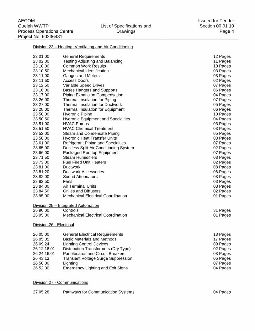
Division 23 – Heating, Ventilating and Air Conditioning 23 01 00 General Requirements 12 Pages 23 02 00 Testing Adjusting and Balancing 11 Pages 23 10 00 Common Work Results 10 Pages 23 10 50 Mechanical Identification 03 Pages 23 11 00 Gauges and Meters 03 Pages 23 11 50 Access Doors 02 Pages 23 12 50 Variable Speed Drives 07 Pages 23 16 00 Bases Hangers and Supports 06 Pages 23 17 00 Piping Expansion Compensation 04 Pages 23 26 00 Thermal Insulation for Piping 07 Pages 23 27 00 Thermal Insulation for Ductwork 05 Pages 23 28 00 Thermal Insulation for Equipment 06 Pages 23 50 00 Hydronic Piping 10 Pages 23 50 50 Hydronic Equipment and Specialties 04 Pages 23 51 00 HVAC Pumps 03 Pages 23 51 50 HVAC Chemical Treatment 03 Pages 23 52 00 Steam and Condensate Piping 05 Pages 23 58 00 Hydronic Heat Transfer Units 03 Pages 23 61 00 Refrigerant Piping and Specialties 07 Pages 23 65 00 Ductless Split Air Conditioning System 02 Pages 23 66 00 Packaged Rooftop Equipment 07 Pages 23 71 50 Steam Humidifiers 03 Pages 23 73 00 Fuel Fired Unit Heaters 02 Pages 23 81 00 Ductwork 08 Pages 23 81 20 Ductwork Accessories 06 Pages 23 82 00 Sound Attenuators 03 Pages 23 82 50 Fans 03 Pages 23 84 00 Air Terminal Units 03 Pages 23 84 50 Grilles and Diffusers 02 Pages 23 95 00 Mechanical Electrical Coordination 01 Pages Division 25 – Integrated Automation 25 90 00 Controls 31 Pages 25 95 00 Mechanical Electrical Coordination 01 Pages Division 26 - Electrical 26 05 00 General Electrical Requirements 13 Pages 26 05 05 Basic Materials and Methods 17 Pages 26 09 24 Lighting Control Devices 09 Pages 26 12 16.01 Distribution Transformers (Dry Type) 02 Pages 26 24 16.01 Panelboards and Circuit Breakers 03 Pages 26 43 13 Transient Voltage Surge Suppression 05 Pages 26 50 00 Lighting 07 Pages 26 52 00 Emergency Lighting and Exit Signs 04 Pages Division 27 - Communications 27 05 28 Pathways for Communication Systems 04 Pages

AECOM Issued for Tender Guelph WWTP List of Specifications and Section 00 01 10 Process Operations Centre Drawings Page 5 Project No. 60236481
Division 31 – Earth Works 31 23 33.01 Excavation Trenching and Backfilling 07 Pages
Division 32 – Exterior Improvements 32 91 21 Topsoil Placement and Grading 02 Pages 32 92 20 Seeding 04 Pages 32 92 23 Sodding 03 Pages 32 93 10 Trees, Shrubs and Groundcover Planting 10 Pages
2 LIST OF DRAWINGS
Following drawings are titled:
Process Operations Centre
530 Wellington Street, Guelph, Ontario
Drawings as prepared by AECOM Canada Architects Ltd. and are identified as Project No. “60236481” and
are Revision “8” dated “01/11/2013” and show “ISSUED FOR TENDER” in the revisions list.
PROCESS OPERATIONS CENTRE – BUILDING A
A-000 COVER SHEET EX1 EXISTING CONDITIONS PLAN SSP1 SITE SERVICING PLAN GP1 SITE GRADING PLAN L1 LANDSCAPE PLAN A-001 LIFE SAFETY PLAN AND BUILDING CODE MATRIX A-002 REFERENCE SHEET A-101 SITE PLAN A-102 SITE DETAILS A-D01 ARCHITECTURAL DEMOLITION FLOOR PLANS A-201 BASEMENT FLOOR PLAN A-202 GROUND FLOOR PLAN A-203 SECOND FLOOR PLAN A-204 ROOF PLAN A-205 BASEMENT AND GROUND FLOOR REFLECTED CEILING PLAN A-206 SECOND FLOOR REFLECTED CEILING PLAN A-301 EXTERIOR ELEVATIONS A-302 EXTERIOR ELEVATIONS A-303 WINDOW SCHEDULE A-304 WINDOW SCHEDULE A-401 BUILDING SECTIONS A-402 BUILDING SECTIONS A-403 STAIR SECTIONS A-404 WALL SECTIONS A-501 SECTION DETAILS A-502 SECTION DETAILS A-503 SECTION DETAILS

AECOM Issued for Tender Guelph WWTP List of Specifications and Section 00 01 10 Process Operations Centre Drawings Page 6 Project No. 60236481
A-601 PLAN DETAILS A-602 PLAN DETAILS A-603 PLAN DETAILS A-701 INTERIOR ELEVATIONS A-702 RECEPTION DESK PLAN AND ELEVATIONS A-703 RECEPTION ROOM - MILLWORK DETAILS A-704 CONTROL ROOM PLAN, ELEVATIONS AND DETAILS A-705 MILLWORK DETAILS A-706 MILLWORK DETAILS A-707 MILLWORK DETAILS A-801 DOOR SCHEDULE A-802 ROOM FINISH PLANS A-803 ROOM FINISH PLAN S-100 GENERAL STRUCTURAL NOTES AND LOADING S-201 FOUNDATION PLAN, COLUMN AND PIER SCHEDULE S-202 SLAB ON GRADE PLAN S-203 CONCRETE SECTIONS AND DETAILS S-204 TYPICAL CONCRETE DETAILS S-205 LINTEL PLAN, LINTEL SCHEDULE AND TYPICAL MASONRY DETAILS S-206 STAIR REINFORCING DETAILS S-301 SECOND FLOOR & LOW ROOF FRAMING PLAN S-302 ROOF FRAMING PLAN S-303 STEEL FRAMING ELEVATIONS S-304 STEEL FRAMING ELEVATIONS S-305 STEEL SECTIONS AND DETAILS M-001 GENERAL NOTES AND LEGENDS MECHANICAL M-100 BASEMENT FLOOR PLAN - PLUMBING AND DRAINAGE M-101 GROUND FLOOR PLAN - PLUMBING AND DRAINAGE M-102 SECOND FLOOR PLAN - PLUMBING AND DRAINAGE M-200 BASEMENT FLOOR PLAN – HVAC M-201 GROUND FLOOR PLAN – HVAC M-202 SECOND FLOOR PLAN – HVAC M-203 ROOF PLAN – HVAC M-300 BASEMENT FLOOR PLAN - HEAT TRANSFER M-301 GROUND FLOOR PLAN - HEAT TRANSFER M-302 SECOND FLOOR PLAN - HEAT TRANSFER M-400 SCHEDULES – MECHANICAL M-401 SCHEDULES – MECHANICAL M-500 CONTROL SCHEMATICS – MECHANICAL M-600 SCHEMATICS AND DETAILS – MECHANICAL M-601 SCHEMATICS AND DETAILS – MECHANICAL M-602 SCHEMATICS AND DETAILS – MECHANICAL E-100 ELECTRICAL GENERAL NOTES AND LEGEND E-101 ELECTRICAL SITE PLAN E-102 ELECTRICAL BASEMENT AND ROOF FLOOR PLAN LIGHTING AND POWER E-103 ELECTRICAL GROUND FLOOR PLAN LIGHTING E-104 ELECTRICAL SECOND FLOOR PLAN LIGHTING E-105 ELECTRICAL GROUND FLOOR PLAN POWER E-106 ELECTRICAL SECOND FLOOR PLAN POWER E-107 ELECTRICAL SINGLE LINE DISTRIBUTION E-108 ELECTRICAL PANEL SCHEDULES E-109 ELECTRICAL SCHEDULES E-110 DETAILS

AECOM Issued for Tender Guelph WWTP List of Specifications and Section 00 01 10 Process Operations Centre Drawings Page 7 Project No. 60236481
Drawings as prepared by AECOM Canada Architects Ltd. and are identified as Project No. “60265897” and
are Revision “2” dated “11/30/12” and show “ISSUED FOR TENDER” in the revisions list.
FLEET STORAGE BUILDING – BUILDING B
B-A-000 COVER SHEET B-A-101 CODE MATRIX, LIFE SAFETY PLAN, AND GENERAL NOTES B-A-102 FLOOR PLAN, ELEVATIONS, AND SECTIONS B-A-103 DETAILS AND SCHEDULES B-S-101 FOUNDATION PLAN, ROOF FRAMING PLAN, AND SECTIONS B-S-102 DETAILS B-M-101 MECHANICAL FLOOR PLANS AND SPECIFICATION B-M-102 MECHANICAL SCHEMATICS, SCHEDULES, AND DETAILS B-E-101 ELECTRICAL LIGHTING PLAN, POWER PLAN, SPECIFICATIONS AND
SCHEDULES
END OF SECTION


AECOM Issued for Tender Guelph WWTP Supplementary Conditions Section 00 73 00 Process Operations Centre Page 1 Project No. 60236481 1.0 General
The following supplements shall modify, delete and/or add to the “General Conditions of the Stipulated Price Contract” of the Standard Construction Document – CCDC#2 – 1994. The Supplementary Conditions shall apply to all Work and shall be read in conjunction with the General Conditions of the Contract.
1.1 Article A-5 Payment .1 Article 5.3.1; modify as follows:
…an award by arbitration or court, interest at one percent (1%) per annum above the bank rate…
1.2 Article A-6 Receipt of and Addresses for Notices .1 Article 6.1; modify as follows: …..or to an officer of the corporation for whom they are intended by hand, by registered post, by facsimile or by email; or if sent by……. 1.3 Definitions .1 Add the following definitions:
21. Completion of the Contract The Contract shall be deemed to be completed when the price of completion or correction of known defects is not more than the lesser of: 1% of Contract Price, or $1,000.00.
22. Total Net Value of Work Total Net Value of Work is used in Change Orders to determine the mark-up for overhead and profit on the change. Total Net Value of Work means the cost of additional work by the Contactor and all Sub-contractors minus the cost of deducted work, without any mark-ups by Contractors or Sub-contractors.
1.4 GC 1.1 Contract Documents
.1 Article 1.1.9.1; modify as follows: ……shall be
Supplementary Conditions
The Agreement between the Owner and the Contractor
The Definitions
The General Conditions…….. .2 Article 1.1.9.5; new paragraph as follows:
If detailed standards in the specifications conflict with the specifications, the specifications shall govern. If specifications conflict with specifications, the more stringent specifications shall govern. If drawings conflict with drawings, the more stringent drawings shall govern.
.3 Article 1.1.10; delete and insert the following:
The Owner shall provide the Contractor up to 20 sets of the Contract Documents to perform the Work. Additional sets may be purchased from the Consultant, at cost plus mark-up.
1.6 GC 2.3 Review and Inspection of Work .1 Article 2.3.2; modify as follows: Delete the phrase “reasonable notice” and replace with “5 Working days notice”. .2 Article 2.3.6; new paragraph as follows:

AECOM Issued for Tender Guelph WWTP Supplementary Conditions Section 00 73 00 Process Operations Centre Page 2 Project No. 60236481
The Owner shall be permitted temporary or trial use of all equipment supplied under the Contract before Substantial Performance of the Work. The Contractor shall supply all labour and materials required for the temporary or trial use. Any damage or breakdown due to faulty materials or Workmanship shall be made good by the Contractor.
1.7 GC 3.1 Control of the Work .1 Article 3.1.3; new paragraph as follows:
Upon award of the Contract by either a letter of intent, a purchase order or the signed Contract, whichever comes first, the Contractor shall submit proper bonding, insurance and WSIB clearance prior to entering the site. Within ten (10) working days of award of the Contract the Contractor shall conduct a preconstruction survey of any existing structures with the Consultant and the Owner. It is at the Contractor’s discretion to perform any intrusive tests and excavations deemed necessary to confirm the condition of such structures and their foundations. The Contractor shall pay for all costs associated with performing such work, and costs for making good any damage associated with such work. Within ten (10) working days of the survey the Contractor and Consultant shall submit a joint report to the Owner summarizing the results. Issues identified in the report not indicated in the Contract Documents that have cost implications, other than minor imperfections and all construction safety issues, devices or systems, will be dealt with as a change to the Contract. The date the report is submitted the Contractor assumes full responsibility for the site and all existing structures and their foundations, including but not limited to all safety, as per GC 3.6 Construction Safety, and maintenance issues, excluding any unforeseen soil conditions. Any temporary services that are in place are the responsibility of the Contractor in all respects whether shown on the drawings or not. If there is any negligence upon the part of the Contractor in maintaining the site, the Contractor will pay for any costs associated with making good the site and any other matters arising out of such negligence.
.2 Article 3.1.4; new paragraph as follows: As time is of the essence the Contractor is responsible to carry out all functions in a timely manner to ensure the Work does not incur any unnecessary delays and is performed within the Contract Time.
1.8 GC 3.4 Document Review .1 Article 3.4.1; modify as follows:
The Contractor shall review the Contract Documents within 10 working days after the date of the Owner’s Letter of Intent, or the date of the Purchase Order, and shall report promptly to the Consultant any error, inconsistency, or omission the Contractor may discover.………..The Contractor shall not be liable for damage or costs resulting from such errors, inconsistencies, or omissions in the Contract Documents, which the Contractor did not discover within this 10 working day period noted above………….
.2 Article 3.4.2; new paragraph as follows:
The Contractor may submit to the Consultant requests for information, clarification or changes to the Contract. Any requests for information, clarification, or changes to the Contract that are already clearly shown, detailed and/or specified in the Contract Documents, according to the Consultant, will be subject to a charge for the Consultants time at their regular hourly rates plus mark-up payable by the Contractor through a credit to the Contract Price. The Contractor may not submit more than three (3) requests for information per day unless agreed to by the Consultant.
1.9 GC 3.5 Construction Schedule .1 Article 3.5.1.1; modify as follows:
……….prior to the first application for payment, a critical path construction schedule that indicates manpower loading and timing of the activities of the Work and provides…..

AECOM Issued for Tender Guelph WWTP Supplementary Conditions Section 00 73 00 Process Operations Centre Page 3 Project No. 60236481
.2 Article 3.5.1.2; modify as follows:
………and update the schedule on a monthly basis indicating progress of each scheduled line item, changes in manpower loading and any changes required to perform the Work in conformity with the Contract Time; and
.3 Article 3.5.2; new paragraph as follows: Failure to submit an appropriate critical path schedule, or failure to submit an appropriate updated
schedule on a monthly basis may result in the withholding of all progress payments which may be due.
1.10 GC 3.6 Construction Safety .1 Article 3.6.2; new paragraph as follows:
Any repetitive or flagrant breach of safety legislation will be considered failure to comply with the requirements of the Contract to a substantial degree.
.2 Article 3.6.3; new paragraph as follows: If the Owner performs work or awards separate contracts for performing work on the site during the
Work of the Contract, then the Contractor agrees to become the constructor for the Owner’s workers or contractor(s). The Owner agrees to pay a fee, including mark-up, of $300 per week for up to ten (10) of the Owner’s workers or contracted workers, or $500 per week for over ten (10) of
the Owner’s workers or contracted workers. The Owner’s contractor(s) will provide copies of insurance, WSIB, safety policy, Canadian Construction Association form 1000, WHMIS training, and fall arrest training to the Contractor.
1.11 GC 3.7 Supervisor .1 Article 3.7.1; modify the second sentence as follows:
The supervisor shall not be changed except for valid reason and as approved by the Consultant and the Owner.
.2 Article 3.7.3; new paragraph as follows: The Contractor shall replace the supervisor with an equivalent or more competent person, if requested by the Consultant, within 10 working days of the request.
1.12 GC 3.9 Labour and Products .1 Article 3.9.1; add the following sentence:
The Contractor shall not be entitled to a change in the Contract Price due to any increase in the cost of labour, materials or equipment regardless if the Contract Time is extended or not.
.2 Article 3.9.2; add the following sentences: All Products which are specified by their proprietary names, part number, or catalogue number are to form the basis for the Tenders. No substitutions allowed. The Contractor may include with his submission alternative prices on a separate sheet of paper from the Tender submission, indicating any effect that the substitution may have on the Contract Price. The Contractor will use all Products in strict accordance with the manufacturer’s directions except when specified otherwise.
.3 Article 3.9.4; new paragraph as follows:
Unless submitted in writing with the Tender, no consideration will be given by the Owner to claims by the Contractor of the unsuitability of any Products, nor to the Contractors unwillingness to use any Products, nor to any relaxation of the requirement to provide good workmanship, nor to the relaxation of the applicable warranties.

AECOM Issued for Tender Guelph WWTP Supplementary Conditions Section 00 73 00 Process Operations Centre Page 4 Project No. 60236481 1.13 GC 3.11 Shop Drawings .1 Article 3.11.3; add the following sentence:
When manufacturer’s literature is submitted in lieu of scaled shop drawings, clearly mark the item(s) to be reviewed.
.2 Article 3.11.4; delete the second sentence and insert the following:
The Contractor shall prepare a schedule of the dates for submission of all shop drawings no later than 10 Working days after the date of the Owner’s Letter of Intent, or the date of the Purchase Order.
.3 Article 3.11.4; add the following sentence:
Failure to submit the shop drawing schedule within the specified period, or failure to submit shop drawings according to the shop drawing schedule may result in the withholding of all progress payments which may be due.
1.14 GC 3.12 Use of the Work .1 Article 3.12.3; add the following sentences:
The Owner shall have the right to enter and occupy the building in whole or in part for the purpose of placing Products and equipment, or for other use or for other work before completion of the Contract provided that, in the opinion of the Consultant, such entry, occupation or work will not prevent or interfere with the Contractor in the performance of the completion of the Contract. Such entry or occupation will not be considered as acceptance of the Work, or in any way relieve the Contractor from his responsibility to complete the Contract on schedule.
1.15 GC 4.1 Cash Allowance .1 Article 4.1.4; modify as follows: Where the total cost for all cash allowance items exceeds the total amount of all cash allowances, the Contractor shall be compensated for any excess incurred and substantiated……. .2 Article 4.1.5; modify as follows: The Contract Price shall be adjusted by Change Order to provide for any difference between the total actual cost and the total cash allowance. 1.16 GC 5.1 Financing Information Required of the Owner Delete this Section in its entirety and all references thereto. 1.17 GC 5.2 Applications for Progress Payment .1 Article 5.2.6; modify as follows:
…….supported by invoices indicating the quantity, description, and value of the Products. If the Products are not incorporated into the Work, then a copy of the Suppliers invoice showing “Paid in Full”, must be attached to the progress claim otherwise the value of these Products may be deducted. Products delivered to the Place of Work are the Contractors responsibility until built-in.
.2 Article 5.2.7; new paragraph as follows:
The Contractor shall submit with each application for progress payment a Certificate of Clearance from the Workers Safety Insurance Board In addition, after the first and with each subsequent application for payment, submit a Statutory Declaration that all accounts for labour, subcontracts, Products and services have been paid to the end of the period covered by the preceding applications, and that none of the material on site has been purchased under a conditional sale or any type of hire-purchase agreement.

AECOM Issued for Tender Guelph WWTP Supplementary Conditions Section 00 73 00 Process Operations Centre Page 5 Project No. 60236481
.3 Article 5.2.8; new paragraph as follows:
Where the specifications indicate a LEED design, a LEED’s assessment review will accompany each request for progress payment, and if there are any deficiencies noted by the Consultant, an appropriate amount, as determined by the Consultant, will be deducted from the progress payment and held until the deficiency is corrected. If the deficiency is not corrected on subsequent payments a larger amount maybe deducted and held. If the deficiency cannot be corrected, then the deficiency amount may not be returned, but deducted from the Contract Price.
1.18 GC 5.3 Progress Payment
.1 Article 5.3.2; modify as follows: Delete the phrase “5 days”, and replace with “30 days”.
1.19 GC 5.4 Substantial Performance of the Work
.1 Article 5.4.3; add the following sentences: If any defects are corrected after Substantial Performance of the Work the Warranty for the Work, with reference to Products and Workmanship in accordance with GC 12.3 Warranty, will start from the date when such defects are corrected. If a designated portion of the Work is Substantially Performed, the Warranty of that portion of the Work will start from the same date when all defects are corrected.
1.20 GC 5.5 Payment of Holdback Upon Substantial Performance of the Work
.1 Article 5.5.1.3: new paragraph as follows: submit evidence of compliance with the Construction Lien Act, 1990, regarding advertisements, indicating date of and name of publication etc., with the application for payment of holdback
.2 Article 5.5.1.4: new paragraph as follows:
submit all specified written guarantees, bonds, maintenance manuals, as-built record drawings, certificates, etc., with the application for payment of holdback
.3 Article 5.5.1.5: new paragraph as follows:
submit a Certificate of Clearance from the Workers Safety Insurance Board, with the application for payment of holdback
.4 Article 5.5.3; delete this article and all references thereto.
1.21 GC 5.7 Final Payment
.1 Article 5.7.1; delete and replace with the following: When the Contractor considers that he has reached the completion of the Work, the Contractor shall submit an application for final payment. In consideration of the completion of the Work, deficiencies or defects will be valued as follows:

AECOM Issued for Tender Guelph WWTP Supplementary Conditions Section 00 73 00 Process Operations Centre Page 6 Project No. 60236481
.1 Approved as-built drawings and maintenance manuals (with warranties, extended warranties, sign-off permits including Hydro Inspection The greater of 0.25% of the Certificate.) Contract Price or $10,000.
.2 Keys $2,000 .3 Clean-up The greater of 0.1% of the Contract Price or $5,000 .4 Other deficiencies or defects Value as per Consultant If the Contractor, directly or indirectly, has the Consultant visit the site to inspect for completion of deficiencies more than two times, then all associated costs for any further deficiency review visits required by the Consultant will be deducted from the Contract Price for payment to the Consultant.
.2 Article 5.7.4; modify as follows: Delete the phrase “5 days”, and replace with “30 days”.
1.22 GC 5.8 Withholding of Payment .1 Article 5.8.2; new paragraph as follows: The Owner may withhold partial payments to cover the cost of any deficiencies as determined by the Consultant. Notwithstanding GC 5.3 Progress Payment, the Owner may withhold all payments as per GC 3.5 Construction Schedule, GC 3.11 Shop Drawings, and GC 6.2 Change Orders. 1.23 GC 6.1 Changes
.1 Article 6.1.3; new paragraph as follows: The Contractor will inform the Bonding Companies of any changes to the Contract so that the Performance Bond still covers the Contract as specified. If any change to the Contract requires adjustments to the Bond, the Contractor is to initiate and pay for the adjustments. Provide proof to the Consultant as requested of the validity of coverage.
1.24 GC 6.2 Change Order
.1 Article 6.2.1; add the following sentences: If the proposed change in the Work will affect the Contract Price or the Contract Time, then the Contractor will provide all quotations detailing the hours of labour, labour rates, payroll burden, itemized materials including quantities and costs, equipment, supervision, overhead & profit. Subcontractors will provide similar information. Mark-ups for overhead and profit (OH&P) will be as per the table below and will be on the Total Net Value of Work for the Contractor and all Subcontractors. [Example: Contractor – additional work $6,000, deduction in work $2,000, net $4,000; Subcontractor – additional work $100,000, deduction in work $40,000, net $60,000; Total Net Value of Work - $64,000; Contractor OH&P 7.5% of $4,000 and 5% of $60,000; Subcontractor OH&P 7.5% of $60,000]. The mark-up for overhead shall include, but not be limited to, office space and all associated costs, copying, printing, phones, fax, utilities, toilets, safety costs and flagmen, project management team members, Contractor supervision, benefits, taxes other than Value Added Taxes, all insurance types, bonding, transportation, temporary space and services, hand tools, delivery costs, and permits, fees and licenses. If the change will affect the critical path schedule to extend the date of Substantial Performance as substantiated by Contractor documentation, then the Contractor may add site supervision costs in addition to OH&P. Once a Change Order is signed, no further claims may be made for Contract Price or Contract Time as it relates to that change.

AECOM Issued for Tender Guelph WWTP Supplementary Conditions Section 00 73 00 Process Operations Centre Page 7 Project No. 60236481
Total Net Value of Work
Contractor mark-up on own work
Subcontractor mark-up on own work
Contractor mark-up on Subcontractor work
Subcontractor mark-up on Subcontractor work
< $5,000 15% 15% 10% 10%
$5,000 < $50,000
10% 10% 5% 5%
$50,000 and over
7.5% 7.5% 5% 3%
.2 Article 6.2.3; new paragraph as follows:
As time is of the essence, the Contractor must submit a price for a pending Change in a reasonable amount of time as determined by the Consultant, but in no case more than ten (10) working days from the date of receipt. The submission must be complete in all respects as outlined in 6.2.1. If the Consultant requests re-pricing of a Change, the re-pricing must be submitted within two (2) working days. Failure to comply with these requirements may result in withholding all progress payments.
1.25 GC 6.3 Change Directive
.1 Article 6.3.1; modify as follows: …..Contractor agreeing upon the adjustment in Contract Price and Contract Time, or if the Owner requires a change to be expedited for any reason, the Owner, through the Consultant, shall issue a Change Directive.
.2 Article 6.3.4.2; delete this article and all references thereto. .3 Article 6.3.4.3; delete this article and all references thereto. .4 Article 6.3.4.4; delete this article and all references thereto. .5 Article 6.3.4.8; add the following statement: provided they are not due to the negligence of the Contractor. .6 Article 6.3.4.12; delete this article and all references thereto. .7 Article 6.3.4.15; delete this article and all references thereto. .8 Article 6.3.5; add the following sentences:
The final amount of any Change Directive can be adjusted based on the determination of the Consultant. If there is agreement on the adjustment to the Contract Price for the change in the Work, then the value of the Change Directive to perform the work shall be as per the agreed to price.
1.26 GC 6.4 Concealed or Unknown Conditions
.1 Article 6.4.2; add the following sentence: Fractured bedrock, clay or broken shale is not considered materially different than granular soils.
1.27 GC 6.5 Delays
.1 Article 6.5.3; add the following sentence: The Contractor shall not be entitled to payment for costs incurred from the settlement of a labour dispute, strike, or lock-out.

AECOM Issued for Tender Guelph WWTP Supplementary Conditions Section 00 73 00 Process Operations Centre Page 8 Project No. 60236481
.2 Article 6.5.4; add the following sentences: The notice of delay, notice of potential delay, impact notice or the like, must be accompanied with complete documentation indicating exactly how the critical path schedule will be affected, otherwise no claim for delay will be allowed. The Consultant has 10 Working Days after receipt of the notice to respond before there is consideration for a change to the Contract, however this time may be extended if the Contractor has not complied with Article 3.4.2.
1.28 GC 7.2 Contractor’s Right to Stop Work or Terminate the Contract
.1 Article 7.2.3.1; delete this article and all references thereto. .2 Article 7.2.5; modify as follows: ……..including reasonable profit to the date of termination. The Contractor’s entitlement shall be determined on the basis of an evaluation of the Work performed and Products supplied under the Contract in relation to the Contract Price plus any Change Orders or Change Directives, for loss sustained upon Products and construction machinery and equipment, and such other damages as the Contractor may have sustained as a result of the termination of the Contract, all as determined by the Consultant.
1.29 GC 8.2 Negotiation, Mediation, and Arbitration
.1 Article 8.2.9; new paragraph as follows: Within five days receipt of the notice of arbitration by the responding party under paragraph 8.2.6 the Owner and/or the Contractor may give the Consultant a written notice containing: .1 a copy of the notice of arbitration; .2 a copy of supplementary conditions 8.29 to 8.2.15 of this Contract, and;
.3 any claims or issues which the Contractor or the Owner, as the case may be, wishes to raise in relation to the Consultant arising out of the issues in dispute in the arbitration.
.2 Article 8.2.10; new paragraph as follows:
The Owner and the Contractor agree that the Consultant may elect, within ten days of receipt of the notice under paragraph 8.2.9, to become a full party to the arbitration under paragraph 8.2.6 if the Consultant: .1 has a vested or contingent financial interest in the outcome of the arbitration;
.2 give the election of notice to the Owner and the Contractor before the arbitrator is appointed; .3 agrees to be a party to the arbitration within the meaning of the rules referred to in paragraph 8.2.6, and; .4 agrees to be bound by the arbitral award made in the arbitration.
.3 Article 8.2.11; new paragraph as follows:
If the Consultant is not given the written notice required under paragraph 8.2.9, both the Owner and the Contractor are estopped from pursuing an action, counter claim or other proceeding or making an application against the Consultant arising out of the issues in dispute in the arbitration between the Owner and the Contractor under paragraph 8.2.6.
.4 Article 8.2.12; new paragraph as follows:
If an election is made under paragraph 8.2.10, the Consultant may participate in the appointment of the arbitrator and notwithstanding the rules referred to in paragraph 8.2.6, the time period for reaching agreement on the appointment of the arbitrator shall begin to run from the date the Owner issues or receives a copy of the notice of arbitration.
.5 Article 8.2.13; new paragraph as follows:
The arbitrator in the arbitration in which the Consultant has elected under paragraph 8.2.10 to become a full party may:

AECOM Issued for Tender Guelph WWTP Supplementary Conditions Section 00 73 00 Process Operations Centre Page 9 Project No. 60236481 .1 on the application of the Owner or the Contractor, determine whether the Consultant has satisfied the requirements of paragraph 8.2.10, and; .2 make any procedural order considered necessary to facilitate the addition of the
Consultant as a party to the arbitration. .6 Article 8.2.14; new paragraph as follows: The provisions of paragraph 8.2.9 shall apply mutatis mutandis to written notice to be given by the Consultant to any sub-consultant. .7 Article 8.2.15; new paragraph as follows:
In the event of notice of arbitration given by a Consultant to a sub-consultant, the sub-consultant is not entitled to any election with respect to the proceeding as outlined in 8.2.10, and is deemed to be bound by the arbitration proceeding.
1.30 GC 9.1 Protection of Work and Property
.1 Article 9.1.4; new paragraph as follows: Where permanent installations or otherwise, such as roads, curbs, sidewalks, boulevards, sod, trees, hydrants, fencing, street lighting, landscaping, buildings or structures, outdoor pools, and other such installed equipment abut, front and/or adjoin the Place of Work, the Contractor shall identify the conditions of same prior to commencement of the Work and record said conditions in such a manner as directed by the Consultant, to indemnify the Owner and the Contractor against subsequent damage which may be alleged by others. Should any damage occur which is attributable to the Contractor, the Contractor shall be responsible to make good such damage at his own expense or pay all costs incurred by others in making good such damage.
1.31 GC 9.3 Toxic and Hazardous Substances and Materials
.1 Article 9.3.3; delete this article and all references thereto. .2 Article 9.3.8; delete this article and all references thereto.
1.32 GC 10.1 Taxes and Duties
.1 Article 10.1.3; new paragraph as follows: When prices are computed for GC 6.2 Change Order, or GC 6.3 Change Directive, the Contractor must exclude the Subcontractor’s and Supplier’s Value Added Taxes from the Contractor’s price.
1.33 GC10.2 Laws, Notices, Permits, and Fees
.1 Article 10.2.2; modify the second sentence as follows: The Contractor shall obtain and pay for permits, licenses, or certificates necessary for the performance of the Work which were in force at the date of bid closing.
1.34 GC 11.1 Insurance
.1 Article 11.1.1.4(3); add the following sentence: As the Owner may be required to provide, maintain and pay for such insurance for total or partial use of the Work, the Owner may deduct all such payments from the Contract Price in the event that the Contractor was negligent in obtaining Substantial Performance within the specified Contract Time as determined by the Consultant.

AECOM Issued for Tender Guelph WWTP Supplementary Conditions Section 00 73 00 Process Operations Centre Page 10 Project No. 60236481 1.35 GC 11.2 Bonds
.1 Article 11.2.1; modify the second sentence as follows: The Contractor shall, prior to commencement of the Work or prior to the signing of the Contract which ever is first, provide to the Owner a Performance Bond and Labour and Material Bond in the amount of 50% of the Contract Price covering faithful performance of the Contract and the payment of all obligations arising thereunder. The premium for the required bond shall be paid by the Contractor.
.2 Article 11.2.3; new paragraph as follows:
The Performance Bond issued by the Surety agrees to repay to the Owner all expenses incurred by the Owner including but not limited to legal fees, additional Consultant fees, security services, heat, and power as a result of its Obliges failure to faithfully perform this Contract whether resulting from the Contractor’s bankruptcy or otherwise.
.3 Article 11.2.4; new paragraph as follows:
The Performance Bond shall continue as a guarantee bond for the warranty period and beyond the warranty period until all deficiencies have been completed to the satisfaction of the Consultant.
1.36 GC 12.1 Indemnification
.1 Article 12.1.1; modify the fourth line as follows: Delete the phrase “provided such claims are:”. .2 Article 12.1.1.1; delete this article and all references thereto. .3 Article 12.1.1.2; delete this article and all references thereto. .4 Article 12.1.1.3; delete this article and all references thereto.
1.37 GC 12.3 Warranty
.1 Article 12.3.1; modify the second line as follows: …….the Work, or from the date when all defects and deficiencies are corrected whichever is later, or those periods specified in the Contract Documents for certain portions of the Work or Products.
.2 Article 12.3.7; new paragraph as follows:
The Contractor shall provide properly executed and signed copies of all Guarantee Bonds, Warranties, and Guarantees containing the Owners name, the name and address of the Project, the date the Guarantee commences, what the Guarantee is covering as per the Specifications, and the signature and seal of the Company issuing the Guarantee countersigned by the Contractor.
END OF SECTION

AECOM Issued for Tender
Guelph WWTP Summary of Work Section 01 11 00 Process Operations Centre Page 1
Project No. 60236481
1 GENERAL
1.01 NOTES
.1 This Division governs work of all other Sections. Sections of Division 1 are complementary and shall be read together with others.
1.02 SPECIFICATION FORMAT
.1 Specifications are not intended as detailed description of installation methods but serve to indicate particular requirements in completed Work.
.2 Where Contract Documents do not provide sufficient information for complete installation of item, then as supplement, comply with manufacturer's written instructions for quality of work.
.3 Portions of Specifications are written in short form. Therefore, it shall be understood that where item of Work is stated in heading followed by material, equipment, component, or operation, words "shall be", "shall consist of" or similar words or phrases are implied which denote supply, fabricate and supply, install, provide or commission of such materials, equipment or operations for component of Work designated by heading.
.4 Where items in Contract Documents are referred to in singular provide as many as required to
complete Work. Words used in one gender only shall mean females and as well as males and conversely.
.5 Whenever used in Specifications the following definitions shall apply: .1 Supply - Procurement or fabrication of standard components not to special design of
materials, equipment, or components, or performance of services to extent indicated. Where used with respect to materials, equipment, or components, term shall include delivery to Site but is not intended to include installation of item, either temporary or final.
.2 Fabricate and Supply - Fabrication of materials, equipment, or component, to special
customized design to extent indicated including delivery to Site, assisting in form of supervision to those Section(s) installing materials, equipment or component. Term does not include installation of item either temporary or final.
.3 Install - Placement of materials, equipment, or components, including receiving, unloading,
transporting, storage, uncrating and installing, and performance of such testing and finish work as is compatible with degree of installation specified complete ready for use.
.4 Provide - To Supply and install complete and in place, including accessories, finishes, tests
and services as required to render item so specified complete ready for use. .5 Commission - Startup and initial operation of equipment as required and/or as specified in
respective Sections, to demonstrate satisfactory operation of components and entire system including calibration of any control instrumentation as required to maintain operations.
.6 Drawings, Lists or Schedules of Items are intended to show scope and arrangement of work. For location of item described refer to such Drawings, Lists or Schedules unless location stipulated in Specifications.
.7 Wherever words "acceptable", "approved", "reviewed", "satisfactory", "selected", "directed", "designated", "permitted", "inspected", "instructed", "clarification", "required", "report", "submit", "obtain", "consult", "advise", or similar words or phrases are used in Standards or in Contract Documents, it shall be understood that, unless context provides otherwise words "by/to/with/from the Consultant" shall follow them as applicable.
.8 Term "NIC" means that work of this Project, which is not being performed or provided under this Contract; term means "Not In this Contract" or "Not a Part of the Work to be Performed by Contractor.”

AECOM Issued for Tender
Guelph WWTP Summary of Work Section 01 11 00 Process Operations Centre Page 2
Project No. 60236481
.9 "NIC" work may be specified or indicated on Drawings as an aid to Contractor in scheduling amount of
time and materials necessary for completion of Contract.
1.03 DISCREPANCIES/CONFLICTS/OMISSIONS
.1 If discrepancies or conflicts in, or omissions from Drawings, Specifications or other Contract Documents are suspected, or if there is doubt as to meaning or intent thereof, notify Consultant immediately. Where there is conflict between Contract Documents, stringent requirements shall prevail.
.2 Drawings, Specifications and other Contract Documents are intended to be in compliance with federal, provincial and municipal laws, by laws, regulations and other requirements of authorities having jurisdiction. Perform work in conformity with such requirements.
.3 Comply with Consultant’s written instructions or explanations.
.4 Contractor shall promptly, and not later than ten 10 working days of becoming aware of circumstances, which may require a change in the Work or other directions, give written notice to Consultant outlining such circumstances and requesting written directions. Do no work in affected area, or that would prevent Consultant from properly assessing situation or evaluating change, without prior written approval. Consultant will act promptly to give Contractor directions so Work is not unreasonably delayed.
1.04 RELATED REQUIREMENTS
.1 Section 00 73 00 – Supplementary Conditions.
.2 Canadian Construction Documents Committee (CCDC) .1 CCDC 2-1994, Stipulated Price Contract.
1.05 WORK COVERED BY CONTRACT DOCUMENTS
.1 Work of this Contract comprises general construction of the Guelph Process Operations Centre, located at 530 Wellington Street West, Guelph, ON at the Guelph Wastewater Treatment Plant.
.2 Work of this Contract includes furnishing labour, materials, equipment, services, and other related expenses to execute complete construction of facility specified under Contract Documents
1.06 CONTRACT METHOD
.1 Construct Work under single, stipulated price contract.
1.07 WORK BY OTHERS
.1 Not Used.
1.08 FUTURE WORK
.1 Not Used.
1.09 WORK SEQUENCE
.1 Maintain fire access/control.
1.10 CONTRACTOR USE OF PREMISES
.1 Unrestricted use of indicated construction area until Substantial Performance. Access and use of remainder of site is limited and must be approved by Owner.

AECOM Issued for Tender
Guelph WWTP Summary of Work Section 01 11 00 Process Operations Centre Page 3
Project No. 60236481
.2 Co-ordinate use of premises under direction of Consultant.
.3 Obtain and pay for use of additional storage or work areas needed for operations under this Contract.
.4 Remove or alter existing work to prevent injury or damage to portions of existing work which remain.
.5 Repair or replace portions of existing work which have been altered during construction operations to match existing or adjoining work, as directed by Consultant.
.6 At completion of operations condition of existing work: equal to or better than that which existed before new work started.
1.11 OWNER OCCUPANCY
.1 Co-operate with Owner in scheduling site operations to minimize conflict and to facilitate Owner usage.
1.12 PARTIAL OWNER OCCUPANCY
.1 Not Used.
1.13 [PRE-ORDERED PRODUCTS] [PRE-BID WORK]
.1 Not Used.
1.14 PRE-PURCHASED EQUIPMENT
.1 Not Used.
1.15 OWNER FURNISHED ITEMS
.1 Not Used.
1.16 ALTERATIONS, ADDITIONS OR REPAIRS TO EXISTING BUILDING
.1 Not Used.
1.17 EXISTING SERVICES
.1 Notify Consultant, Owner and utility companies of intended interruption of services and obtain required
permission.
.2 Where Work involves breaking into or connecting to existing services, give Consultant and Owner 72 hours notice for necessary interruption of mechanical or electrical service throughout course of work. Minimize duration of interruptions. Carry out work at times as directed by governing authorities with minimum disturbance to pedestrian, vehicular traffic and tenant operations.
.3 Provide alternative routes for personnel and vehicular traffic.
.4 Establish location and extent of service lines in area of work before starting Work. Notify Consultant and Owner of findings.
.5 Submit schedule to and obtain approval from Consultant and Owner for any shut-down or closure of active service or facility including power and communications services. Adhere to approved schedule and provide notice to affected parties.
.6 Provide temporary services to maintain critical building and Owner operation systems.
.7 Provide adequate bridging over trenches which cross sidewalks or roads to permit normal traffic.

AECOM Issued for Tender
Guelph WWTP Summary of Work Section 01 11 00 Process Operations Centre Page 4
Project No. 60236481
.8 Where unknown services are encountered, immediately advise Consultant and confirm findings in
writing.
.9 Protect, relocate or maintain existing active services. When inactive services are encountered, cap off in manner approved by authorities having jurisdiction.
.10 Record locations of maintained, re-routed and abandoned service lines.
.11 Construct barriers in accordance with Section 01 56 00 - Temporary Barriers and Enclosures.
1.18 DOCUMENTS REQUIRED
.1 Maintain at job site, one copy each document as follows: .1 Contract Drawings. .2 Specifications. .3 Addenda. .4 Reviewed Shop Drawings.
.5 List of Outstanding Shop Drawings.
.6 Change Orders.
.7 Other Modifications to Contract.
.8 Field Test Reports.
.9 Copy of Approved Work Schedule.
.10 Health and Safety Plan and Other Safety Related Documents.
.11 Other documents as specified.
2 PRODUCTS
2.01 NOT USED
.1 Not Used.
3 EXECUTION
3.01 NOT USED
.1 Not Used.
END OF SECTION

AECOM Issued for Tender Guelph WWTP Work Restrictions Section 01 14 00 Process Operations Centre Page 1 Project No. 60236481
1 GENERAL
1.01 NOTES
.1 All conditions of the Contract apply to the work of this Section.
1.02 RELATED REQUIREMENTS
.1 Section 01 11 00 – Summary of Work.
1.03 ACCESS AND EGRESS
.1 Design, construct and maintain temporary "access to" and "egress from" work areas, including stairs, runways, ramps or ladders and scaffolding, independent of finished surfaces and in accordance with relevant municipal, provincial and other regulations.
1.04 USE OF SITE AND FACILITIES
.1 Execute work with least possible interference or disturbance to normal use of premises. Make arrangements with Owner to facilitate work as stated.
.2 Maintain existing services to site and provide for personnel and vehicle access.
.3 Where security is reduced by work provide temporary means to maintain security.
.4 Closures: protect work temporarily until permanent enclosures are completed.
1.05 ALTERATIONS, ADDITIONS OR REPAIRS TO EXISTING BUILDING
.1 Not Used.
1.06 EXISTING SERVICES
.1 Notify Consultant and Owner and utility companies of intended interruption of services and obtain required permission.
.2 Where Work involves breaking into or connecting to existing services, give Consultant and Owner 72 hours of notice for necessary interruption of mechanical or electrical service throughout course of work. Keep duration of interruptions minimum. Carry out interruptions after normal working hours of occupants, preferably on weekends.
.3 Provide for personnel and vehicular traffic.
.4 Construct barriers in accordance with Section 01 56 00 - Temporary Barriers and Enclosures.
1.07 SPECIAL REQUIREMENTS
.1 Submit schedule in accordance with Section [01 32 16.06 - Construction Progress Schedule - Critical Path Method (CPM)] [01 32 16.07 - Construction Progress Schedules - Bar (GANTT) Chart].
.2 Ensure that Contractor personnel employed on site become familiar with and obey regulations including safety, fire, traffic and security regulations.
.3 Keep within limits of work and avenues of ingress and egress.
.4 Ingress and egress of Contractor vehicles at site is limited to south west service vehicle access.

AECOM Issued for Tender Guelph WWTP Work Restrictions Section 01 14 00 Process Operations Centre Page 2 Project No. 60236481 1.08 SECURITY CLEARANCES
.1 Not Used.
1.09 SECURITY ESCORT
.1 Not Used.
1.10 BUILDING SMOKING ENVIRONMENT
.1 Comply with smoking restrictions. Smoking is not allowed.
2 PRODUCTS
2.01 NOT USED
.1 Not Used.
3 EXECUTION
3.01 NOT USED
.1 Not Used.
END OF SECTION

AECOM Issued for Tender Guelph WWTP Allowances Section 01 21 00 Process Operations Centre Page 1 Project No. 60236481
1 GENERAL
1.01 NOTES
.1 All conditions of the Contract apply to the work of this Section.
1.02 REFERENCES
.1 Canadian Construction Documents Committee (CCDC) .1 CCDC 2-1994, Stipulated Price Contract.
.2 Project Supplementary Conditions
1.03 CASH ALLOWANCES
.1 Refer to CCDC 2, GC 4.1.
.2 Include in Contract Price specified cash allowances.
.3 Cash allowances, unless otherwise specified, cover net cost to Contractor of services, products, construction machinery and equipment, freight, handling, unloading, storage installation and other authorized expenses incurred in performing Work.
.4 Contract Price, and not cash allowance, includes Contractor's overhead and profit in connection with such cash allowance.
.5 Contract Price will be adjusted by written order to provide for excess or deficit to each cash allowance.
.6 Where costs under a cash allowance exceed amount of allowance, Contractor will be compensated for excess incurred and substantiated plus allowance for overhead and profit as set out in Contract Documents.
.7 Include progress payments on accounts of work authorized under cash allowances in Consultant's monthly certificate for payment.
.8 Prepare schedule jointly with Consultant and Contractor to show when items called for under cash allowances must be authorized by Consultant for ordering purposes so that progress of Work will not be delayed.
.9 Amount of each allowance, for Work specified in respective specification is as follows: .1 $ 40,000 for purchase of Door Hardware in accordance with Section 08 71 00. .2 $ 8,000 for purchase of Interior Signage in accordance with Section 10 14 00. .3 $ 5,000 for purchase and installation of Parking Signage as indicated on drawings. .4 $ 20,000 for Testing and Inspection. .5 $ 3,000 for Construction Site Signage.
1.04 CONTINGENCY ALLOWANCE
.1 Refer to CCDC 2, GC 4.2.
.2 Expenditures under contingency allowance will be authorized in accordance with procedures provided in CCDC 2, GC 6.1 - Changes CCDC 2, 6.2 Change Order and CCDC 2, 6.3 Change Directive.

AECOM Issued for Tender Guelph WWTP Allowances Section 01 21 00 Process Operations Centre Page 2 Project No. 60236481 2 PRODUCTS
2.01 NOT USED
.1 Not Used.
3 EXECUTION
3.01 NOT USED
.1 Not Used.
END OF SECTION

AECOM Issued for Tender Guelph WWTP Payment Procedures Section 01 29 00 Process Operations Centre Page 1 Project No. 60236481
1 GENERAL
1.01 NOTES
.1 All conditions of the Contract apply to the work of this Section.
1.02 REFERENCES
.1 Owner/Contractor Agreement.
.2 Canadian Construction Documents Committee (CCDC) .1 CCDC 2-1994, Stipulated Price Contract.
1.03 APPLICATIONS FOR PROGRESS PAYMENT
.1 Refer to CCDC 2.
.2 Make applications for payment on account as provided in Agreement, monthly as Work progresses.
.3 Date applications for payment last day of agreed monthly payment period and ensure amount claimed is for value, proportionate to amount of Contract, of Work performed and Products delivered to Place of Work at that date.
.4 Submit to Consultant, at least fourteen (14) days before first application for payment. Schedule of values for parts of Work, aggregating total amount of Contract Price, to facilitate evaluation of applications for payment.
1.04 SCHEDULE OF VALUES
.1 Refer to CCDC 2.
.2 Provide schedule of values supported by evidence as Consultant may reasonably direct and when accepted by Consultant, be used as basis for applications for payment.
.3 Include statement based on schedule of values with each application for payment.
.4 Support claims for products delivered to Place of Work but not yet incorporated into Work by such evidence as Consultant may reasonably require to establish value and delivery of products.
1.05 PREPARING SCHEDULE OF UNIT PRICE TABLE ITEMS
.1 Submit separate schedule of unit price items of Work requested in Bid form.
.2 Make form of submittal parallel to Schedule of Values, with each line item identified same as line item in Schedule of Values. Include in unit prices only: .1 Cost of material. .2 Delivery and unloading at site. .3 Sales taxes. .4 Installation, overhead and profit.
.3 Ensure unit prices multiplied by quantities given equal material cost of that item in Schedule of Values.
1.06 PROGRESS PAYMENT
.1 Refer to CCDC 2.
.2 Consultant will issue to Owner, no later than ten (10) days after receipt of an application for payment,

AECOM Issued for Tender Guelph WWTP Payment Procedures Section 01 29 00 Process Operations Centre Page 2 Project No. 60236481
certificate for payment in amount applied for or in such other amount as Consultant determines to be due. If Consultant amends application, Consultant will give notification in writing giving reasons for amendment.
1.07 SUBSTANTIAL PERFORMANCE OF WORK
.1 Refer to CCDC 2.
.2 Prepare and submit to Consultant comprehensive list of items to be completed or corrected and apply for a review by Consultant to establish Substantial Performance of Work or substantial performance of designated portion of Work when Work is substantially performed if permitted by lien legislation applicable to Place of Work designated portion which Owner agrees to accept separately is substantially performed. Failure to include items on list does not alter responsibility to complete Contract.
.3 No later than ten (10) days after receipt of list and application, Consultant will review Work to verify validity of application, and no later than seven (7) days after completing review, will notify Contractor if Work or designated portion of Work is substantially performed.
.4 Consultant: state date of Substantial Performance of Work or designated portion of Work in certificate.
.5 Immediately following issuance of certificate of Substantial Performance of Work, in consultation with Consultant, establish reasonable date for finishing Work.
1.08 PAYMENT OF HOLDBACK UPON SUBSTANTIAL PERFORMANCE OF WORK
.1 Refer to CCDC 2.
.2 After issuance of certificate of Substantial Performance of Work: .1 Submit application for payment of holdback amount. .2 Submit sworn statement that accounts for labour, subcontracts, products, construction
machinery and equipment, and other indebtedness which may have been incurred in Substantial Performance of Work and for which Owner might in be held responsible have been paid in full, except for amounts properly retained as holdback or as identified amount in dispute.
.3 After receipt of application for payment and sworn statement, Consultant will issue certificate for payment of holdback amount.
.4 Where holdback amount has not been placed in a separate holdback account, Owner shall, ten (10) days prior to expiry of holdback period stipulated in lien legislation applicable to Place of Work, place holdback amount in bank account in joint names of Owner and Contractor.
.5 Amount authorized by certificate for payment of holdback amount is due and payable on day following expiration of holdback period stipulated in lien legislation applicable to Place of Work. Where lien legislation does not exist or apply, holdback amount is due and payable in accordance with other legislation, industry practice, or provisions which may be agreed to between parties. Owner may retain out of holdback amount sums required by law to satisfy liens against Work or, if permitted by lien legislation applicable to Place of Work, other third party monetary claims against Contractor which are enforceable against Owner.
1.09 PROGRESSIVE RELEASE OF HOLDBACK
.1 Refer to CCDC 2.
.2 Where legislation permits, if Consultant has certified that Work of subcontractor or supplier has been performed prior to Substantial Performance of Work, Owner shall pay holdback amount retained for

AECOM Issued for Tender Guelph WWTP Payment Procedures Section 01 29 00 Process Operations Centre Page 3 Project No. 60236481
such subcontract Work, or products supplied by such supplier, on day following expiration of holdback period for such Work stipulated in lien legislation applicable to Place of Work.
.3 In addition to provisions of preceding paragraph, and certificate wording, ensure that such subcontract Work or products is protected pending issuance of final certificate for payment and be responsible for correction of defects or Work not performed regardless of whether or not such was apparent when such certificates were issued.
1.10 FINAL PAYMENT
.1 Refer to CCDC 2, GC 5.7.
.2 Submit application for final payment when Work is completed.
.3 Consultant will, no later than ten (10) days after receipt of application for final payment, review Work to verify validity of application. Consultant will give notification that application is valid or give reasons why it is not valid, no later than seven (7) days after reviewing Work.
.4 Consultant will issue final certificate for payment when application for final payment is found valid.
2 PRODUCTS
2.01 NOT USED
.1 Not Used.
3 EXECUTION
3.01 NOT USED
.1 Not Used.
END OF SECTION


AECOM Issued for Tender Guelph WWTP Payment Procedures Section 01 29 83 Process Operations Centre for Testing Laboratory Services Page 1 Project No. 60236481
1 GENERAL
1.01 NOTES
.1 All conditions of the Contract apply to the work of this Section.
1.02 RELATED REQUIREMENTS
.1 Particular requirements for inspection and testing to be carried out by testing laboratory designated by Consultant are specified under various sections.
1.03 APPOINTMENT AND PAYMENT
.1 Consultant shall appoint for services of testing laboratory.
.2 Contractor shall pay for services of testing laboratory all costs for tests are to be from the Material Testing Allowance as specified in Section 01 21 00 – Allowances.
.3 Owner shall not pay for services of testing laboratory and costs of tests shall not be charged to the Material Testing Allowance if: .1 Inspection and testing required by laws, ordinances, rules, regulations or orders of public
authorities. .2 Inspection and testing performed exclusively for Contractor's convenience. .3 Testing, adjustment and balancing of conveying systems, mechanical and electrical
equipment and systems. .4 Mill tests and certificates of compliance. .5 Tests specified to be carried out by [Contractor] under the supervision of Consultant. .6 Additional tests specified as follows:
.1 Where tests or inspections by designated testing laboratory reveal Work not in accordance with contract requirements, pay costs for additional tests or inspections as required by Consultant to verify acceptability of corrected work.
1.04 CONTRACTOR'S RESPONSIBILITIES
.1 Provide labour, equipment and facilities to: .1 Provide access to Work for inspection and testing. .2 Facilitate inspections and tests.
.2 Make good Work disturbed by inspection and test.
.3 Provide storage on site for laboratory's exclusive use to store equipment and cure test samples.
.4 Notify Consultant sufficiently in advance of operations to allow for assignment of laboratory personnel and scheduling of test.
.5 Where materials are specified to be tested, deliver representative samples in required quantity to testing laboratory.
.6 Pay costs for uncovering and making good Work that is covered before required inspection or testing is completed and approved by Consultant.

AECOM Issued for Tender Guelph WWTP Payment Procedures Section 01 29 83 Process Operations Centre for Testing Laboratory Services Page 2 Project No. 60236481 2 PRODUCTS
2.01 NOT USED
.1 Not Used.
3 EXECUTION
3.01 NOT USED
.1 Not Used.
END OF SECTION

AECOM Issued for Tender Guelph WWTP Project Meetings Section 01 31 19 Process Operations Centre Page 1 Project No. 60236481
1 GENERAL
1.01 NOTES
.1 All Conditions of contract apply to the work of this Section.
1.02 RELATED REQUIREMENTS
.1 Section 01 11 00 – Summary Work.
.2 Section 01 14 00 – Work Restrictions.
1.03 ADMINISTRATIVE
.1 Schedule and administer project meetings [throughout the progress of the work] at the call of Consultant.
.2 Prepare agenda for meetings.
.3 Distribute written notice of each meeting [four] days in advance of meeting date to Consultant.
.4 Provide physical space and make arrangements for meetings.
.5 Preside at meetings.
.6 Record the meeting minutes. Include significant proceedings and decisions. Identify actions by parties.
.7 Reproduce and distribute copies of minutes within three days after meetings and transmit to meeting participants and, affected parties not in attendance including the Owner, Consultant and Clerk of Works.
.8 Representative of Contractor, Subcontractor and suppliers attending meetings will be qualified and authorized to act on behalf of party each represents.
1.04 PRECONSTRUCTION MEETING
.1 Within 15 days after award of Contract, request a meeting of parties in contract to discuss and resolve administrative procedures and responsibilities.
.2 Senior representatives of Owner, Consultant, Contractor, major Subcontractors, field inspectors and supervisors will be in attendance.
.3 Establish time and location of meeting and notify parties concerned minimum 5 days before meeting.
.4 Incorporate mutually agreed variations to Contract Documents into Agreement, prior to signing.
.5 Agenda to include: .1 Appointment of official representative of participants in the Work. .2 Schedule of Work: in accordance Section 01 32 16.07 - Construction Progress Schedules -
Bar (GANTT) Chart. .3 Schedule of submission of shop drawings, samples, colour chips. Submit submittals in
accordance with Section 01 33 00 - Submittal Procedures. .4 Requirements for temporary facilities, site sign, offices, storage sheds, utilities, fences in
accordance with Section 01 52 00 - Construction Facilities.

AECOM Issued for Tender Guelph WWTP Project Meetings Section 01 31 19 Process Operations Centre Page 2 Project No. 60236481
.5 Delivery schedule of specified equipment in accordance with applicable Sections.
.6 Site security in accordance with Section 01 56 00 - Temporary Barriers and Enclosures.
.7 Proposed changes, change orders, procedures, approvals required, mark-up percentages permitted, time extensions, overtime, administrative requirements.
.8 Owner provided products.
.9 Record drawings in accordance with Section 01 33 00 - Submittal Procedures.
.10 Maintenance manuals in accordance with Section 01 78 00 - Closeout Submittals.
.11 Take-over procedures, acceptance, warranties in accordance with Section 01 78 00 - Closeout Submittals.
.12 Monthly progress claims, administrative procedures, photographs, hold backs.
.13 Appointment of inspection and testing agencies or firms.
.14 Insurances, transcript of policies.
1.05 PROGRESS MEETINGS
.1 During course of Work, schedule progress meetings bi-weekly.
.2 Contractor, major Subcontractors involved in Work, Consultant, Owner and Clerks of Work are to be in attendance.
.3 Notify parties minimum four days prior to meetings.
.4 Record minutes of meetings and circulate to attending parties and affected parties not in attendance within three days after meeting.
.5 Agenda to include the following: .1 Review, approval of minutes of previous meeting. .2 Review of Work progress since previous meeting. .3 Field observations, problems, conflicts. .4 Problems which impede construction schedule. .5 Review of off-site fabrication delivery schedules. .6 Corrective measures and procedures to regain projected schedule. .7 Revision to construction schedule. .8 Progress schedule, during succeeding work period. .9 Review submittal schedules: expedite as required. .10 Maintenance of quality standards. .11 Review proposed changes for affect on construction schedule and on completion date. .12 Other business.
2 PRODUCTS
2.01 NOT USED
.1 Not Used.
3 EXECUTION
3.01 NOT USED
.1 Not Used.
END OF SECTION

AECOM Issued for Tender Guelph WWTP Construction Progress Schedule- Section 01 32 16.07 Process Operations Centre Bar (Gantt) Chart Page 1 Project No. 60236481
1 GENERAL
1.01 NOTES
.1 All conditions of the Contract apply to the work of this Section.
1.02 RELATED REQUIREMENTS
.1 Section 01 11 00 – Summary of Work.
1.03 DEFINITIONS
.1 Activity: element of Work performed during course of Project. Activity normally has expected duration, and expected cost and expected resource requirements. Activities can be subdivided into tasks.
.2 Bar Chart (GANTT Chart): graphic display of schedule-related information. In typical bar chart, activities or other Project elements are listed down left side of chart, dates are shown across top, and activity durations are shown as date-placed horizontal bars. Generally Bar Chart should be derived from commercially available computerized project management system.
.3 Baseline: original approved plan (for project, work package, or activity), plus or minus approved scope changes.
.4 Construction Work Week: Monday to Friday, inclusive, will provide five day work week and define schedule calendar working days as part of Bar (GANTT) Chart submission.
.5 Duration: number of work periods (not including holidays or other nonworking periods) required to complete activity or other project element. Usually expressed as workdays or workweeks.
.6 Master Plan: summary-level schedule that identifies major activities and key milestones.
.7 Milestone: significant event in project, usually completion of major deliverable.
.8 Project Schedule: planned dates for performing activities and the planned dates for meeting milestones. Dynamic, detailed record of tasks or activities that must be accomplished to satisfy Project objectives. Monitoring and control process involves using Project Schedule in executing and controlling activities and is used as basis for decision making throughout project life cycle.
.9 Project Planning, Monitoring and Control System: overall system operated by Consultant to enable monitoring of project work in relation to established milestones.
1.04 REQUIREMENTS
.1 Ensure Master Plan and Detail Schedules are practical and remain within specified Contract duration.
.2 Plan to complete Work in accordance with prescribed milestones and time frame.
.3 Limit activity durations to maximum of approximately ten (10) working days, to allow for progress reporting.
.4 Ensure that it is understood that Award of Contract or time of beginning, rate of progress, Interim Certificate and Final Certificate as defined times of completion are of essence of this contract.
1.05 ACTION AND INFORMATIONAL SUBMITTALS
.1 Provide submittals in accordance with Section 01 33 00 - Submittal Procedures.
AECOM Issued for Tender Guelph WWTP Construction Progress Schedule- Section 01 32 16.07 Process Operations Centre Bar (Gantt) Chart Page 2 Project No. 60236481
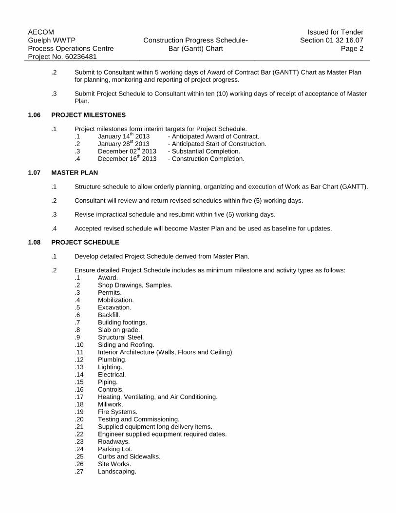
.2 Submit to Consultant within 5 working days of Award of Contract Bar (GANTT) Chart as Master Plan for planning, monitoring and reporting of project progress.
.3 Submit Project Schedule to Consultant within ten (10) working days of receipt of acceptance of Master Plan.
1.06 PROJECT MILESTONES
.1 Project milestones form interim targets for Project Schedule. .1 January 14
th 2013 - Anticipated Award of Contract.
.2 January 28st 2013 - Anticipated Start of Construction.
.3 December 02st 2013 - Substantial Completion.
.4 December 16th 2013 - Construction Completion.
1.07 MASTER PLAN
.1 Structure schedule to allow orderly planning, organizing and execution of Work as Bar Chart (GANTT).
.2 Consultant will review and return revised schedules within five (5) working days.
.3 Revise impractical schedule and resubmit within five (5) working days.
.4 Accepted revised schedule will become Master Plan and be used as baseline for updates.
1.08 PROJECT SCHEDULE
.1 Develop detailed Project Schedule derived from Master Plan.
.2 Ensure detailed Project Schedule includes as minimum milestone and activity types as follows: .1 Award. .2 Shop Drawings, Samples. .3 Permits. .4 Mobilization. .5 Excavation. .6 Backfill. .7 Building footings. .8 Slab on grade. .9 Structural Steel. .10 Siding and Roofing. .11 Interior Architecture (Walls, Floors and Ceiling). .12 Plumbing. .13 Lighting. .14 Electrical. .15 Piping. .16 Controls. .17 Heating, Ventilating, and Air Conditioning. .18 Millwork. .19 Fire Systems. .20 Testing and Commissioning. .21 Supplied equipment long delivery items. .22 Engineer supplied equipment required dates. .23 Roadways. .24 Parking Lot. .25 Curbs and Sidewalks. .26 Site Works. .27 Landscaping.

AECOM Issued for Tender Guelph WWTP Construction Progress Schedule- Section 01 32 16.07 Process Operations Centre Bar (Gantt) Chart Page 3 Project No. 60236481 1.09 PROJECT SCHEDULE REPORTING
.1 Update Project Schedule on bi-weekly basis reflecting activity changes and completions, as well as activities in progress.
.2 Include as part of Project Schedule, narrative report identifying Work status to date, comparing current progress to baseline, presenting current forecasts, defining problem areas, anticipated delays and impact with possible mitigation.
1.10 PROJECT MEETINGS
.1 Discuss Project Schedule at regular site meetings, identify activities that are behind schedule and provide measures to regain slippage. Activities considered behind schedule are those with projected start or completion dates later than current approved dates shown on baseline schedule.
.2 Weather related delays with their remedial measures will be discussed and negotiated.
2 PRODUCTS
2.01 NOT USED
.1 Not Used.
3 EXECUTION
3.01 NOT USED
.1 Not Used.
END OF SECTION


AECOM Issued for Tender Guelph WWTP Submittal Procedures Section 01 33 00 Process Operations Centre Page 1 Project No. 60236481
1 GENERAL
1.01 NOTES
.1 All conditions of the Contract apply to the work of this Section.
1.02 RELATED REQUIREMENTS
.1 Section 01 11 00 – Summary of Work.
1.03 REFERENCES
.1 Canadian Construction Documents Committee (CCDC) .1 CCDC 2-1994, Stipulated Price Contract.
1.04 ADMINISTRATIVE
.1 Submit to Consultant submittals listed for review. Submit promptly and in orderly sequence to not cause delay in Work. Failure to submit in ample time is not considered sufficient reason for extension of Contract Time and no claim for extension by reason of such default will be allowed.
.2 Contractor is to submit a shop drawing submission schedule to the Consultant for review and comments prior to start of construction.
.3 Do not proceed with Work affected by submittal until review is complete.
.4 Present shop drawings, product data, samples and mock-ups in SI Metric units.
.5 Where items or information is not produced in SI Metric units converted values are acceptable.
.6 Review submittals prior to submission to Consultant. This review represents that necessary requirements have been determined and verified, or will be, and that each submittal has been checked and co-ordinated with requirements of Work and Contract Documents. Submittals not stamped, signed, dated and identified as to specific project will be returned without being examined and considered rejected.
.7 Notify Consultant, in writing at time of submission, identifying deviations from requirements of Contract Documents stating reasons for deviations.
.8 Verify field measurements and affected adjacent Work are co-ordinated.
.9 Contractor's responsibility for errors and omissions in submission is not relieved by Consultant's review of submittals.
.10 Contractor's responsibility for deviations in submission from requirements of Contract Documents is not relieved by Consultant review.
.11 Keep one reviewed copy of each submission on site.
1.05 SHOP DRAWINGS AND PRODUCT DATA
.1 Refer to CCDC 2 GC 3.11.
.2 The term "shop drawings" means drawings, diagrams, illustrations, schedules, performance charts, brochures and other data which are to be provided by Contractor to illustrate details of a portion of Work.

AECOM Issued for Tender Guelph WWTP Submittal Procedures Section 01 33 00 Process Operations Centre Page 2 Project No. 60236481
.3 Submit drawings stamped and signed by professional engineer registered or licensed in the Province of Ontario, Canada.
.4 Indicate materials, methods of construction and attachment or anchorage, erection diagrams, connections, explanatory notes and other information necessary for completion of Work. Where articles or equipment attach or connect to other articles or equipment, indicate that such items have been co-ordinated, regardless of Section under which adjacent items will be supplied and installed. Indicate cross references to design drawings and specifications.
.5 Allow 14 days for Consultant's review of each submission.
.6 Adjustments made on shop drawings by Consultant are not intended to change Contract Price. If adjustments affect value of Work, state such in writing to Consultant prior to proceeding with Work.
.7 Make changes in shop drawings as Consultant may require, consistent with Contract Documents. When resubmitting, notify Consultant in writing of revisions other than those requested.
.8 Accompany submissions with transmittal letter containing: .1 Date. .2 Project title and number. .3 Contractor's name and address. .4 Identification and quantity of each shop drawing, product data and sample. .5 Other pertinent data.
.9 Submissions include: .1 Date and revision dates. .2 Project title and number. .3 Name and address of:
.1 Subcontractor.
.2 Supplier.
.3 Manufacturer. .4 Contractor's stamp, signed by Contractor's authorized representative certifying approval of
submissions, verification of field measurements and compliance with Contract Documents. .5 Details of appropriate portions of Work as applicable:
.1 Fabrication.
.2 Layout, showing dimensions, including identified field dimensions, and clearances.
.3 Setting or erection details.
.4 Capacities.
.5 Performance characteristics.
.6 Standards.
.7 Operating weight.
.8 Wiring diagrams.
.9 Single line and schematic diagrams.
.10 Relationship to adjacent work.
.10 After Consultant's review, distribute copies.
.11 Submit 5 prints and 1 electronic copy of shop drawings for each requirement requested in specification Sections and as Consultant may reasonably request.
.12 Submit 5 prints and 1 electronic copy of product data sheets or brochures for requirements requested in specification Sections and as requested by Consultant where shop drawings will not be prepared due to standardized manufacture of product.
.13 Submit 5 prints and electronic copies of test reports for requirements requested in specification Sections and as requested by [Consultant]. .1 Report signed by authorized official of testing laboratory that material, product or system

AECOM Issued for Tender Guelph WWTP Submittal Procedures Section 01 33 00 Process Operations Centre Page 3 Project No. 60236481
identical to material, product or system to be provided has been tested in accord with specified requirements.
.2 Testing must have been within 3 years of date of contract award for project.
.14 Submit 5 prints and 1 electronic copy of certificates for requirements requested in specification Sections and as requested by Consultant. .1 Statements printed on manufacturer's letterhead and signed by responsible officials of
manufacturer of product, system or material attesting that product, system or material meets specification requirements.
.2 Certificates must be dated after award of project contract complete with project name.
.15 Submit 5 prints and 1 electronic copy of manufacturers instructions for requirements requested in specification Sections and as requested by Consultant. .1 Pre-printed material describing installation of product, system or material, including special
notices and Material Safety Data Sheets concerning impedances, hazards and safety precautions.
.16 Submit 5 prints and 1 electronic copy of Manufacturer's Field Reports for requirements requested in specification Sections and as requested by Consultant.
.17 Documentation of the testing and verification actions taken by manufacturer's representative to confirm compliance with manufacturer's standards or instructions.
.18 Submit 5 prints and 1 electronic copy of Operation and Maintenance Data for requirements requested in specification Sections and as requested by Consultant.
.19 Delete information not applicable to project.
.20 Supplement standard information to provide details applicable to project.
.21 If upon review by Consultant, no errors or omissions are discovered or if only minor corrections are made, copies will be returned and fabrication and installation of Work may proceed. If shop drawings are rejected, noted copy will be returned and resubmission of corrected shop drawings, through same procedure indicated above, must be performed before fabrication and installation of Work may proceed.
.22 The review of shop drawings by the Consultant is for sole purpose of ascertaining conformance with general concept. .1 This review shall not mean that the Consultant approves detail design inherent in shop
drawings, responsibility for which shall remain with Contractor submitting same, and such review shall not relieve Contractor of responsibility for errors or omissions in shop drawings or of responsibility for meeting requirements of construction and Contract Documents.
.2 Without restricting generality of foregoing, Contractor is responsible for dimensions to be confirmed and correlated at job site, for information that pertains solely to fabrication processes or to techniques of construction and installation and for co-ordination of Work of sub-trades.
1.06 SAMPLES
.1 Submit for review samples in duplicate as requested in respective specification Sections. Label samples with origin and intended use.
.2 Deliver samples prepaid to Consultant's business address.
.3 Notify Consultant in writing, at time of submission of deviations in samples from requirements of Contract Documents.

AECOM Issued for Tender Guelph WWTP Submittal Procedures Section 01 33 00 Process Operations Centre Page 4 Project No. 60236481
.4 Where colour, pattern or texture is criterion, submit full range of samples.
.5 Adjustments made on samples by Consultant are not intended to change Contract Price. If adjustments affect value of Work, state such in writing to Consultant prior to proceeding with Work.
.6 Make changes in samples which Consultant may require, consistent with Contract Documents.
.7 Reviewed and accepted samples will become standard of workmanship and material against which installed Work will be verified.
1.07 MOCK-UPS
.1 Erect mock-ups in accordance with 01 45 00 - Quality Control.
1.08 PHOTOGRAPHIC DOCUMENTATION
.1 Submit electronic copy of colour digital photography in jpg format and standard resolution, monthly with progress statement and as directed by Consultant.
.2 Project identification: name and number of project and date of exposure indicated.
.3 Number of viewpoints: 4 locations. .1 Viewpoints and their location as determined by Consultant.
.4 Frequency of photographic documentation: weekly as directed by Consultant. .1 Upon completion of: excavation, foundation, framing and services before concealment, of
Work, as directed by Consultant.
1.09 CERTIFICATES AND TRANSCRIPTS
.1 Immediately after award of Contract, submit Workers' Compensation Board status.
.2 Submit transcription of insurance immediately after award of Contract.
2 PRODUCTS
2.01 NOT USED
.1 Not Used.
3 EXECUTION
3.01 NOT USED
.1 Not Used.
END OF SECTION
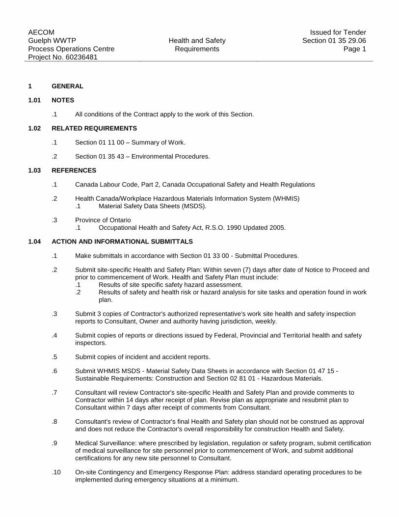
AECOM Issued for Tender Guelph WWTP Health and Safety Section 01 35 29.06 Process Operations Centre Requirements Page 1 Project No. 60236481
1 GENERAL
1.01 NOTES
.1 All conditions of the Contract apply to the work of this Section.
1.02 RELATED REQUIREMENTS
.1 Section 01 11 00 – Summary of Work.
.2 Section 01 35 43 – Environmental Procedures.
1.03 REFERENCES
.1 Canada Labour Code, Part 2, Canada Occupational Safety and Health Regulations
.2 Health Canada/Workplace Hazardous Materials Information System (WHMIS) .1 Material Safety Data Sheets (MSDS).
.3 Province of Ontario .1 Occupational Health and Safety Act, R.S.O. 1990 Updated 2005.
1.04 ACTION AND INFORMATIONAL SUBMITTALS
.1 Make submittals in accordance with Section 01 33 00 - Submittal Procedures.
.2 Submit site-specific Health and Safety Plan: Within seven (7) days after date of Notice to Proceed and prior to commencement of Work. Health and Safety Plan must include: .1 Results of site specific safety hazard assessment. .2 Results of safety and health risk or hazard analysis for site tasks and operation found in work
plan.
.3 Submit 3 copies of Contractor's authorized representative's work site health and safety inspection reports to Consultant, Owner and authority having jurisdiction, weekly.
.4 Submit copies of reports or directions issued by Federal, Provincial and Territorial health and safety inspectors.
.5 Submit copies of incident and accident reports.
.6 Submit WHMIS MSDS - Material Safety Data Sheets in accordance with Section 01 47 15 - Sustainable Requirements: Construction and Section 02 81 01 - Hazardous Materials.
.7 Consultant will review Contractor's site-specific Health and Safety Plan and provide comments to Contractor within 14 days after receipt of plan. Revise plan as appropriate and resubmit plan to Consultant within 7 days after receipt of comments from Consultant.
.8 Consultant's review of Contractor's final Health and Safety plan should not be construed as approval and does not reduce the Contractor's overall responsibility for construction Health and Safety.
.9 Medical Surveillance: where prescribed by legislation, regulation or safety program, submit certification of medical surveillance for site personnel prior to commencement of Work, and submit additional certifications for any new site personnel to Consultant.
.10 On-site Contingency and Emergency Response Plan: address standard operating procedures to be implemented during emergency situations at a minimum.
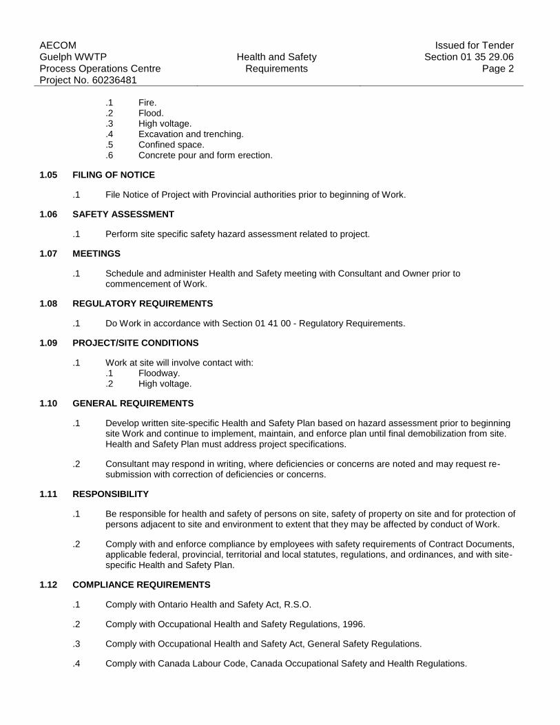
AECOM Issued for Tender Guelph WWTP Health and Safety Section 01 35 29.06 Process Operations Centre Requirements Page 2 Project No. 60236481
.1 Fire.
.2 Flood.
.3 High voltage.
.4 Excavation and trenching.
.5 Confined space.
.6 Concrete pour and form erection.
1.05 FILING OF NOTICE
.1 File Notice of Project with Provincial authorities prior to beginning of Work.
1.06 SAFETY ASSESSMENT
.1 Perform site specific safety hazard assessment related to project.
1.07 MEETINGS
.1 Schedule and administer Health and Safety meeting with Consultant and Owner prior to commencement of Work.
1.08 REGULATORY REQUIREMENTS
.1 Do Work in accordance with Section 01 41 00 - Regulatory Requirements.
1.09 PROJECT/SITE CONDITIONS
.1 Work at site will involve contact with: .1 Floodway. .2 High voltage.
1.10 GENERAL REQUIREMENTS
.1 Develop written site-specific Health and Safety Plan based on hazard assessment prior to beginning site Work and continue to implement, maintain, and enforce plan until final demobilization from site. Health and Safety Plan must address project specifications.
.2 Consultant may respond in writing, where deficiencies or concerns are noted and may request re-submission with correction of deficiencies or concerns.
1.11 RESPONSIBILITY
.1 Be responsible for health and safety of persons on site, safety of property on site and for protection of persons adjacent to site and environment to extent that they may be affected by conduct of Work.
.2 Comply with and enforce compliance by employees with safety requirements of Contract Documents, applicable federal, provincial, territorial and local statutes, regulations, and ordinances, and with site-specific Health and Safety Plan.
1.12 COMPLIANCE REQUIREMENTS
.1 Comply with Ontario Health and Safety Act, R.S.O.
.2 Comply with Occupational Health and Safety Regulations, 1996.
.3 Comply with Occupational Health and Safety Act, General Safety Regulations.
.4 Comply with Canada Labour Code, Canada Occupational Safety and Health Regulations.

AECOM Issued for Tender Guelph WWTP Health and Safety Section 01 35 29.06 Process Operations Centre Requirements Page 3 Project No. 60236481 1.13 UNFORSEEN HAZARDS
.1 When unforeseen or peculiar safety-related factor, hazard, or condition occur during performance of Work, follow procedures in place for Employee's Right to Refuse Work in accordance with Acts and Regulations of Province having jurisdiction and advise Consultant verbally and in writing.
1.14 HEALTH AND SAFETY CO-ORDINATOR
.1 Employ and assign to Work, competent and authorized representative as Health and Safety Co-ordinator. Health and Safety Co-ordinator must: .1 Have working knowledge of occupational safety and health regulations. .2 Be responsible for completing Contractor's Health and Safety Training Sessions and ensuring
that personnel not successfully completing required training are not permitted to enter site to perform Work.
.3 Be responsible for implementing, enforcing daily and monitoring site-specific Contractor's Health and Safety Plan.
.4 Be on site during execution of Work.
1.15 POSTING OF DOCUMENTS
.1 Ensure applicable items, articles, notices and orders are posted in conspicuous location on site in accordance with Acts and Regulations of Province having jurisdiction, and in consultation with Consultant.
1.16 CORRECTION OF NON-COMPLIANCE
.1 Immediately address health and safety non-compliance issues identified by authority having jurisdiction or by Consultant.
.2 Provide Consultant with written report of action taken to correct non-compliance of health and safety issues identified.
.3 Consultant may stop Work if non-compliance of health and safety regulations is not corrected.
1.17 BLASTING
.1 Blasting or other use of explosives is not permitted without prior receipt of written instruction by Consultant.
1.18 POWDER ACTUATED DEVICES
.1 Use powder actuated devices only after receipt of written permission from Consultant.
1.19 WORK STOPPAGE
.1 Give precedence to safety and health of public and site personnel and protection of environment over cost and schedule considerations for Work.
2 PRODUCTS
2.01 NOT USED
.1 Not Used.

AECOM Issued for Tender Guelph WWTP Health and Safety Section 01 35 29.06 Process Operations Centre Requirements Page 4 Project No. 60236481 3 EXECUTION
3.01 NOT USED
.1 Not Used.
END OF SECTION
AECOM Issued for Tender Guelph WWTP Environmental Procedures Section 01 35 43 Process Operations Centre Page 1 Project No. 60236481
1 GENERAL
1.01 NOTES
.1 All conditions of the Contract apply to the work of this Section.
1.02 RELATED REQUIREMENTS
.1 Section 01 11 00 – Summary of Work.
.2 Section 01 35 29 – Health and Safety Requirements.
1.03 REFERENCES
.1 Definitions: .1 Environmental Pollution and Damage: presence of chemical, physical, biological elements or
agents which adversely affect human health and welfare; unfavourably alter ecological balances of importance to human life; affect other species of importance to humankind; or degrade environment aesthetically, culturally and/or historically.
.2 Environmental Protection: prevention/control of pollution and habitat or environment disruption during construction. Control of environmental pollution and damage requires consideration of land, water, and air; biological and cultural resources; and includes management of visual aesthetics; noise; solid, chemical, gaseous, and liquid waste; radiant energy and radioactive material as well as other pollutants.
.2 Reference Standards: .1 Canadian Construction Documents Committee (CCDC)
.1 CCDC 2-1994 Stipulated Price Contract. .2 U.S. Environmental Protection Agency (EPA)/Office of Water
.1 EPA 832/R-92-005-92, Storm Water Management for Construction Activities, Chapter 3.
1.04 ACTION AND INFORMATIONAL SUBMITTALS
.1 Provide submittals in accordance with Section 01 33 00 - Submittal Procedures.
.2 Prior to commencing construction activities or delivery of materials to site, provide Environmental Protection Plan for review and approval by Consultant.
.3 Ensure Environmental Protection Plan includes comprehensive overview of known or potential environmental issues to be addressed during construction.
.4 Address topics at level of detail commensurate with environmental issue and required construction task[s].
.5 Include in Environmental Protection Plan: .1 Name[s] of person[s] responsible for ensuring adherence to Environmental Protection Plan. .2 Name[s] and qualifications of person[s] responsible for manifesting hazardous waste to be
removed from site. .3 Name[s] and qualifications of person[s] responsible for training site personnel. .4 Descriptions of environmental protection personnel training program. .5 Erosion and sediment control plan identifying type and location of erosion and sediment
controls to be provided including monitoring and reporting requirements to assure that control measures are in compliance with erosion and sediment control plan, Federal, Provincial, and Municipal laws and regulations[, EPA 832/R-92-005, Chapter 3 requirements].

AECOM Issued for Tender Guelph WWTP Environmental Procedures Section 01 35 43 Process Operations Centre Page 2 Project No. 60236481
.6 Drawings showing locations of proposed temporary excavations or embankments for haul roads, stream crossings, material storage areas, structures, sanitary facilities, and stockpiles of excess or spoil materials including methods to control runoff and to contain materials on site.
.7 Traffic Control Plans including measures to reduce erosion of temporary roadbeds by construction traffic, especially during wet weather. Ensure plans include measures to minimize amount of mud transported onto paved public roads by vehicles or runoff.
.8 Work area plan showing proposed activity in each portion of area and identifying areas of limited use or non-use. Ensure plan includes measures for marking limits of use areas and methods for protection of features to be preserved within authorized work areas.
.9 Spill Control Plan including procedures, instructions, and reports to be used in event of unforeseen spill of regulated substance.
.10 Non-Hazardous solid waste disposal plan identifying methods and locations for solid waste disposal including clearing debris.
.11 Air pollution control plan detailing provisions to assure that dust, debris, materials, and trash, are contained on project site.
.12 Contaminant Prevention Plan identifying potentially hazardous substances to be used on job site; intended actions to prevent introduction of such materials into air, water, or ground; and detailing provisions for compliance with Federal, Provincial, and Municipal laws and regulations for storage and handling of these materials.
.13 Waste Water Management Plan identifying methods and procedures for management and/or discharge of waste waters which are directly derived from construction activities, such as concrete curing water, clean-up water, dewatering of ground water, disinfection water, hydrostatic test water, and water used in flushing of lines.
.14 Historical, archaeological, cultural resources biological resources and wetlands plan that defines procedures for identifying and protecting historical, archaeological, cultural resources, biological resources and wetlands.
.15 Pesticide treatment plan to be included and updated, as required.
1.05 FIRES
.1 Fires and burning of rubbish on site not permitted.
.2 Provide supervision, attendance and fire protection measures as directed.
1.06 DRAINAGE
.1 Provide Erosion and Sediment Control Plan identifying type and location of erosion and sediment controls provided. Ensure plan includes monitoring and reporting requirements to assure that control measures are in compliance with erosion and sediment control plan, Federal, Provincial, and Municipal laws and regulations, EPA 832/R-92-005, Chapter 3 requirements.
.2 Storm Water Pollution Prevention Plan (SWPPP) to be substituted for erosion and sediment control plan.
.3 Provide temporary drainage and pumping required to keep excavations and site free from water.
.4 Ensure pumped water into waterways, sewer or drainage systems is free of suspended materials.
.5 Control disposal or runoff of water containing suspended materials or other harmful substances in accordance with local authority requirements.
1.07 SITE CLEARING AND PLANT PROTECTION
.1 Protect trees and plants on site and adjacent properties as indicated.
.2 Wrap in burlap, trees and shrubs adjacent to construction work, storage areas and trucking lanes, and

AECOM Issued for Tender Guelph WWTP Environmental Procedures Section 01 35 43 Process Operations Centre Page 3 Project No. 60236481
encase with protective wood framework from grade level to height of [2] m minimum.
.3 Protect roots of designated trees to dripline during excavation and site grading to prevent disturbance or damage. Avoid unnecessary traffic, dumping and storage of materials over root zones.
.4 Minimize stripping of topsoil and vegetation.
.5 Restrict tree removal to areas indicated or designated by Consultant.
1.08 WORK ADJACENT TO WATERWAYS
.1 Construction equipment to be operated on land only.
.2 Do not use waterway beds for borrow material.
.3 Waterways to be free of excavated fill, waste material and debris.
1.09 POLLUTION CONTROL
.1 Maintain temporary erosion and pollution control features installed under this Contract.
.2 Control emissions from equipment and plant to local authorities' emission requirements.
.3 Prevent sandblasting and other extraneous materials from contaminating air and waterways beyond application area. .1 Provide temporary enclosures where directed by Consultant.
.4 Cover or wet down dry materials and rubbish to prevent blowing dust and debris. Provide dust control for temporary roads.
1.10 HISTORICAL/ARCHAEOLOGICAL CONTROL
.1 Provide historical, archaeological, cultural resources biological resources and wetlands plan that defines procedures for identifying and protecting historical, archaeological, cultural resources, biological resources and wetlands known to be on project site: and/or identifies procedures to be followed if historical archaeological, cultural resources, biological resources and wetlands not previously known to be onsite or in area are discovered during construction.
.2 Plan: include methods to assure protection of known or discovered resources and identify lines of communication between Contractor personnel Consultant.
1.11 NOTIFICATION
.1 Consultant will notify Contractor in writing of observed noncompliance with Federal, Provincial or Municipal environmental laws or regulations, permits, and other elements of Contractor's Environmental Protection plan.
.2 Contractor: after receipt of such notice, inform Consultant and Owner of proposed corrective action and take such action for approval by Consultant. .1 Do not take action until after receipt of written approval by Consultant.
.3 Consultant will issue stop order of work until satisfactory corrective action has been taken.
.4 No time extensions granted or equitable adjustments allowed to Contractor for such suspensions.
AECOM Issued for Tender Guelph WWTP Environmental Procedures Section 01 35 43 Process Operations Centre Page 4 Project No. 60236481 2 PRODUCTS
2.01 NOT USED
.1 Not Used.
3 EXECUTION
3.01 CLEANING
.1 Clean in accordance with Section 01 74 11 - Cleaning.
.2 Waste Management: separate waste materials for reuse and recycling.
.3 Rubbish and waste materials are not permitted to be buried on site.
.4 Ensure public waterways, storm and sanitary sewers remain free of waste and volatile materials disposal.
END OF SECTION

AECOM Issued for Tender Guelph WWTP Regulatory Requirements Section 01 41 00 Process Operations Centre Page 1 Project No. 60236481
1 GENERAL
1.01 NOTES
.1 All conditions of the Contract apply to the work of this Section.
1.02 RELATED REQUIREMENTS
.1 Section 01 11 00 – Summary of Work.
.2 Section 01 35 29 – Health and Safety Requirements.
.3 Section 01 35 43 – Environmental Procedures.
1.03 REFERENCES AND CODES
.1 Perform Work in accordance with Ontario Building Code 2006 (OBC) including amendments up to tender closing date and other codes of provincial or local application provided that in case of conflict or discrepancy, more stringent requirements apply.
.2 Meet or exceed requirements of: .1 Contract documents. .2 Specified standards, codes and referenced documents.
1.04 HAZARDOUS MATERIAL DISCOVERY
.1 Asbestos: demolition of spray or trowel-applied asbestos is hazardous to health. Stop work immediately when material resembling spray or trowel-applied asbestos is encountered during demolition work. Notify Consultant.
.2 PCB: Polychlorinated Biphenyl: stop work immediately when material resembling Polychlorinated Biphenyl is encountered during demolition work. Notify Consultant.
.3 Mould: stop work immediately when material resembling mould is encountered during demolition work. Notify Consultant.
1.05 BUILDING SMOKING ENVIRONMENT
.1 Comply with smoking restrictions and municipal by-laws.
1.06 NATIONAL PARKS ACT
.1 Not used.
2 PRODUCTS
2.01 NOT USED
3 EXECUTION
3.01 NOT USED
END OF SECTION


AECOM Issued for Tender Guelph WWTP Quality Control Section 01 45 00 Process Operations Centre Page 1 Project No. 60236481
1 GENERAL
1.01 NOTES
.1 All conditions of contract apply to the work of this Section.
1.02 RELATED REQUIREMENTS
.1 Section 01 11 00 – Summary of Work.
.2 Section 01 21 00 – Allowances
.3 Section 01 61 00 – Common Product Requirements.
1.03 REFERENCES
.1 Canadian Construction Documents Committee (CCDC) .1 CCDC 2-1994, Stipulated Price Contract.
1.04 INSPECTION
.1 Refer to CCDC 2, GC 2.3.
.2 Allow Consultant access to Work. If part of Work is in preparation at locations other than Place of Work, allow access to such Work whenever it is in progress.
.3 Give timely notice requesting inspection if Work is designated for special tests, inspections or approvals by Consultant instructions, or law of Place of Work.
.4 If Contractor covers or permits to be covered Work that has been designated for special tests, inspections or approvals before such is made, uncover such Work, have inspections or tests satisfactorily completed and make good such Work.
.5 Consultant will order part of Work to be examined if Work is suspected to be not in accordance with Contract Documents. If, upon examination such work is found not in accordance with Contract Documents, correct such Work and pay cost of examination and correction. If such Work is found in accordance with Contract Documents, Owner shall pay cost of examination and replacement.
1.05 INDEPENDENT INSPECTION AGENCIES
.1 Independent Inspection/Testing Agencies will be engaged by Owner for purpose of inspecting and/or testing portions of Work.
.2 Costs and payments for such testing and inspection shall be from the applicable Cash Allowances established in Section 01 21 00 Allowances and respective other Sections.
.3 Provide equipment required for executing inspection and testing by appointed agencies.
.4 Employment of inspection/testing agencies does not relax responsibility to perform Work in accordance with Contract Documents.
.5 If defects are revealed during inspection and/or testing, appointed agency will request additional inspection and/or testing to ascertain full degree of defect. Correct defect and irregularities as advised by Consultant at no cost to Owner. Pay costs for retesting and reinspection.
.6 The following items are not included in the Cash Allowances for testing and inspection and costs for

AECOM Issued for Tender Guelph WWTP Quality Control Section 01 45 00 Process Operations Centre Page 2 Project No. 60236481
same shall be included in the Contract Price: .1 Inspection and testing required by laws, rules, regulations or orders of public authorities. .2 Inspection and testing performed exclusively for Contractor's convenience. .3 Testing, adjustment and balancing of mechanical and electrical equipment and systems. .4 Mill tests and certificates of compliance. .5 Tests specified to be carried out by Contractor under the direction of the Consultant
1.06 ACCESS TO WORK
.1 Allow inspection/testing agencies access to Work, off site manufacturing and fabrication plants.
.2 Co-operate to provide reasonable facilities for such access.
.3 Contractor's Responsibilities: The Contractor shall: .1 Provide equipment required for executing inspection and testing by appointed agencies. .2 Facilitate inspections and tests. .3 Make good work disturbed by inspection and testing. .4 Provide storage on site for laboratory's exclusive use to store equipment and cure test
samples.
1.07 PROCEDURES
.1 Notify appropriate agency and Consultant in advance of requirement for tests, in order that attendance arrangements can be made.
.2 Submit samples and/or materials required for testing, as specifically requested in specifications. Submit with reasonable promptness and in orderly sequence to not cause delays in Work.
.3 Provide labour and facilities to obtain and handle samples and materials on site. Provide sufficient space to store and cure test samples.
1.08 REJECTED WORK
.1 Refer to CCDC, GC 2.4.
.2 Remove defective Work, whether result of poor workmanship, use of defective products or damage and whether incorporated in Work or not, which has been rejected by Consultant as failing to conform to Contract Documents. Replace or re-execute in accordance with Contract Documents.
.3 Make good other Contractor's work damaged by such removals or replacements promptly.
.4 If in opinion of Consultant it is not expedient to correct defective Work or Work not performed in accordance with Contract Documents, Owner will deduct from Contract Price difference in value between Work performed and that called for by Contract Documents, amount of which will be determined by Consultant.
1.09 REPORTS
.1 Submit 3 copies of inspection and test reports to Consultant.
.2 Provide copies to subcontractor of work being inspected or tested and/or the manufacturer or fabricator of material being inspected or tested.
1.10 TESTS AND MIX DESIGNS
.1 Furnish test results and mix designs as requested.
.2 Cost of tests and mix designs beyond those called for in Contract Documents or beyond those

AECOM Issued for Tender Guelph WWTP Quality Control Section 01 45 00 Process Operations Centre Page 3 Project No. 60236481
required by law of Place of Work will be appraised by Consultant and may be authorized as recoverable.
1.11 MOCK-UPS
.1 Prepare mock-ups for Work specifically requested in specifications. Include for Work of Sections required to provide mock-ups.
.2 Construct in locations acceptable to Consultant as specified in specific Section.
.3 Prepare mock-ups for Consultant's review with reasonable promptness and in orderly sequence, to not cause delays in Work.
.4 Failure to prepare mock-ups in ample time is not considered sufficient reason for extension of Contract Time and no claim for extension by reason of such default will be allowed.
.5 Remove mock-up at conclusion of Work or when acceptable to Consultant.
.6 Mock-ups may remain as part of Work as approved by Consultant.
.7 Specification section identifies whether mock-up may remain as part of Work or if it is to be removed and when.
1.12 MILL TESTS
.1 Submit mill test certificates as requested.
1.13 EQUIPMENT AND SYSTEMS
.1 Submit adjustment and balancing reports for mechanical, electrical and building equipment systems.
.2 Refer to respective Sections for definitive requirements.
2 PRODUCTS
2.01 NOT USED
.1 Not Used.
3 EXECUTION
3.01 NOT USED
.1 Not Used.
END OF SECTION


AECOM Issued for Tender Guelph WWTP Temporary Utilities Section 01 51 00 Process Operations Centre Page 1 Project No. 60236481
1 GENERAL
1.01 NOTES
.1 All conditions of the Contract apply to the work of this Section.
1.02 RELATED REQUIREMENTS
.1 Section 01 52 00 – Construction Facilities.
.2 Section 01 56 00 – Temporary Barriers and Enclosures.
1.03 REFERENCES
.1 U.S. Environmental Protection Agency (EPA) / Office of Water .1 EPA 832R92005, Storm Water Management for Construction Activities: Developing Pollution
Prevention Plans and Best Management Practices.
1.04 ACTION AND INFORMATIONAL SUBMITTALS
.1 Provide submittals in accordance with Section 01 33 00 - Submittal Procedures.
1.05 INSTALLATION AND REMOVAL
.1 Provide temporary utilities controls in order to execute work expeditiously.
.2 Remove from site all such work after use.
.3 Maintain temporary utilities and plant in good operating order.
1.06 DEWATERING
.1 Provide temporary drainage and pumping facilities to keep excavations and site free from standing water.
1.07 WATER SUPPLY
.1 Owner will provide continuous supply of potable water for construction use.
1.08 TEMPORARY HEATING AND VENTILATION
.1 Provide temporary heating required during construction period, including attendance, maintenance and fuel.
.2 Construction heaters used inside building must be vented to outside or be non-flameless type. Solid fuel salamanders are not permitted.
.3 Provide temporary heat and ventilation in enclosed areas as required to: .1 Facilitate progress of Work. .2 Protect Work and products against dampness and cold. .3 Prevent moisture condensation on surfaces. .4 Provide ambient temperatures and humidity levels for storage, installation and curing of
materials. .5 Provide adequate ventilation to meet health regulations for safe working environment.
.4 Maintain temperatures of minimum 10 degrees C in areas where construction is in progress.

AECOM Issued for Tender Guelph WWTP Temporary Utilities Section 01 51 00 Process Operations Centre Page 2 Project No. 60236481
.5 Ventilating:
.1 Prevent accumulations of dust, fumes, mists, vapours or gases in areas occupied during construction.
.2 Provide local exhaust ventilation to prevent harmful accumulation of hazardous substances into atmosphere of occupied areas.
.3 Dispose of exhaust materials in manner that will not result in harmful exposure to persons.
.4 Ventilate storage spaces containing hazardous or volatile materials.
.5 Ventilate temporary sanitary facilities.
.6 Continue operation of ventilation and exhaust system for time after cessation of work process to assure removal of harmful contaminants.
.6 Permanent heating system of building, not to be used.
.7 On completion of Work, replace all filters and leave equipment clean.
.8 Maintain strict supervision of operation of temporary heating and ventilating equipment to: .1 Conform with applicable codes and standards. .2 Enforce safe practices. .3 Prevent abuse of services. .4 Prevent damage to finishes. .5 Vent direct-fired combustion units to outside.
.9 Be responsible for damage to Work due to failure in providing adequate heat and protection during construction.
1.09 TEMPORARY POWER AND LIGHT
.1 Contractor will provide and pay for temporary power during construction for temporary lighting and operating of power tools, to a maximum supply of 110 volts 15 amps.
.2 Arrange for connection with appropriate utility company. Pay costs for installation, maintenance and removal.
.3 Temporary power for electric cranes and other equipment requiring in excess of above is responsibility of Contractor.
.4 Provide and maintain temporary lighting throughout project. Ensure level of illumination on all floors and stairs is not less than 162 lx.
1.10 TEMPORARY COMMUNICATION FACILITIES
.1 Provide and pay for temporary telephone, fax, and data hook up, lines and equipment necessary for own use and use of Consultant.
1.11 FIRE PROTECTION
.1 Provide and maintain temporary fire protection equipment during performance of Work required by insurance companies having jurisdiction and governing codes, regulations and bylaws.
.2 Burning rubbish and construction waste materials is not permitted on site.
2 PRODUCTS
2.01 NOT USED
.1 Not Used.

AECOM Issued for Tender Guelph WWTP Temporary Utilities Section 01 51 00 Process Operations Centre Page 3 Project No. 60236481
3 EXECUTION
3.01 TEMPORARY EROSION AND SEDIMENTATION CONTROL
.1 Provide temporary erosion and sedimentation control measures to prevent soil erosion and discharge of soil-bearing water runoff or airborne dust to adjacent properties and walkways, according to requirements of authorities having jurisdiction sediment and erosion control drawings sediment and erosion control plan, specific to site, that complies with EPA 832/R-92-005 or requirements of authorities having jurisdiction, whichever is more stringent.
.2 Inspect, repair, and maintain erosion and sedimentation control measures during construction until permanent vegetation has been established.
.3 Remove erosion and sedimentation controls and restore and stabilize areas disturbed during removal.
END OF SECTION


AECOM Issued for Tender Guelph WWTP Construction Facilities Section 01 52 00 Process Operations Centre Page 1 Project No. 60236481
1 GENERAL
1.01 NOTES
.1 All conditions of the Contract apply to the work of this Section.
1.02 RELATED REQUIREMENTS
.1 Section 01 51 00 – Temporary Utilities.
.2 Section 01 56 00 – Temporary Barriers and Enclosures.
1.03 REFERENCES
.1 Canadian Construction Documents Committee (CCDC) .1 CCDC 2-1994, Stipulated Price Contract.
.2 Canadian General Standards Board (CGSB) .1 CAN/CGSB 1.189-00, Exterior Alkyd Primer for Wood. .2 CGSB 1.59-97, Alkyd Exterior Gloss Enamel.
.3 Canadian Standards Association (CSA International) .1 CSA-A23.1/A23.2-04, Concrete Materials and Methods of Concrete Construction/Methods of
Test and Standard Practices for Concrete. .2 CSA-0121-M1978(R2003), Douglas Fir Plywood. .3 CAN/CSA-S269.2-M1987(R2003), Access Scaffolding for Construction Purposes. .4 CAN/CSA-Z321-96(R2001), Signs and Symbols for the Occupational Environment.
.4 U.S. Environmental Protection Agency (EPA) / Office of Water .1 EPA 832R92005, Storm Water Management for Construction Activities: Developing Pollution
Prevention Plans and Best Management Practices.
1.04 ACTION AND INFORMATIONAL SUBMITTALS
.1 Provide submittals in accordance with Section 01 33 00 - Submittal Procedures.
1.05 INSTALLATION AND REMOVAL
.1 Prepare site plan indicating proposed location and dimensions of area to be fenced and used by Contractor, number of trailers to be used, avenues of ingress/egress to fenced area and details of fence installation.
.2 Identify areas which have to be gravelled to prevent tracking of mud.
.3 Indicate use of supplemental or other staging area.
.4 Provide construction facilities in order to execute work expeditiously.
.5 Remove from site all such work after use.
1.06 SCAFFOLDING
.1 Scaffolding in accordance with CAN/CSA-S269.2.
.2 Provide and maintain scaffolding, ramps, ladders, swing staging, platforms and temporary stairs.

AECOM Issued for Tender Guelph WWTP Construction Facilities Section 01 52 00 Process Operations Centre Page 2 Project No. 60236481 1.07 HOISTING
.1 Provide, operate and maintain hoists and cranes required for moving of workers, materials and equipment. Make financial arrangements with Subcontractors for their use of hoists.
.2 Hoists and cranes to be operated by qualified operator.
1.08 ELEVATORS
.1 Not Used.
1.09 SITE STORAGE/LOADING
.1 Refer to CCDC 2, GC 3.12.
.2 Confine work and operations of employees by Contract Documents. Do not unreasonably encumber premises with products.
.3 Do not load or permit to load any part of Work with weight or force that will endanger Work or any part of existing structures, components or elements.
.4 The General Work Contractor shall provide, maintain and remove chutes for the disposal of debris from several floor levels, for the use of Contractors. Chutes might not be provided at every floor level. Each Contractor shall be responsible for disposing of his own waste material, including transport between floor levels as required.
.5 All Trades to supply their own job site Trailer and storage as needed. Existing facilities will not be available for this use.
1.10 CONSTRUCTION PARKING
.1 Parking will be permitted on site provided it does not disrupt performance of Work and parking required by Owner. Owner’s parking requirements take precedence over Contractor’s use of site. Parking will be as directed by the Owner.
.2 Provide and maintain adequate access to project site.
1.11 SECURITY
.1 Provide and pay for responsible security personnel to guard site and contents of site after working hours and during holidays.
1.12 OFFICES
.1 Provide office heated to 22 degrees C, lighted 750 lx and ventilated, of sufficient size to accommodate site meetings and furnished with drawing laydown table.
.2 Provide marked and fully stocked first-aid case in a readily available location.
.3 Subcontractors to provide their own offices as necessary. Direct location of these offices.
.4 Clerk of Works' Site office. .1 Provide temporary office for Clerk of Works. .2 Inside dimensions minimum 3.6 m long x 3 m wide x 2.4 m high, with floor 0.3 m above grade,
complete with 4 50% opening windows and one lockable door. .3 Insulate building and provide heating system to maintain 22 degrees C inside temperature at -
20 degrees C outside temperature. .4 Finish inside walls and ceiling with plywood, hardboard or wallboard and paint in selected

AECOM Issued for Tender Guelph WWTP Construction Facilities Section 01 52 00 Process Operations Centre Page 3 Project No. 60236481
colours. Finish floor with 19 mm thick plywood. .5 Install electrical lighting system to provide min 750 lx using surface mounted, shielded
commercial fixtures with 10 % upward light component. .6 Provide private washroom facilities adjacent to office complete with flush or chemical type
toilet, lavatory and mirror and maintain supply of paper towels and toilet tissue. .7 Equip office with 1 x 2 m table, 2 chairs, 6 m of shelving 300 mm wide, one 3 drawer filing
cabinet, one plan rack and one coat rack and shelf. .8 Maintain in clean condition. .9 Private site office (secure and climate controlled). .10 Standard office desk with two office chairs. .11 One filing cabinet. .12 Drawing table. .13 Phone line with phone. .14 High speed internet. .15 Fax line with fax machine (only if project requires, email and pdf’s over internet instead). .16 A project laptop with current version of Microsoft Windows, Adobe, CAD viewing software etc. .17 A multi-function colour printer/scanner/copier/fax. .18 Printer cartridges. .19 Copier paper. .20 Binders/file folders. .21 Miscellaneous office supplies (staples/binder clips etc.).
1.13 EQUIPMENT, TOOL AND MATERIALS STORAGE
.1 Provide and maintain, in clean and orderly condition, lockable weatherproof sheds for storage of tools, equipment and materials.
.2 Locate materials not required to be stored in weatherproof sheds on site in manner to cause least interference with work activities.
1.14 SANITARY FACILITIES
.1 Provide sanitary facilities for work force in accordance with governing regulations and ordinances.
.2 Post notices and take precautions as required by local health authorities. Keep area and premises in sanitary condition.
.3 When permanent water and drain connections are completed, provide temporary water closets and urinals complete with temporary enclosures, inside building. Permanent facilities may be used on approval of Owner.
1.15 CONSTRUCTION SIGNAGE
.1 Provide and erect project sign, within two weeks of signing Contract, in a location designated by Consultant.
.2 Construction sign 3.0 x 2.4 m at least 1.2 m off the ground, of wood frame and plywood construction painted with exhibit lettering produced by a professional sign painter.
.3 Indicate on sign, name of Owner, Consultant and Contractor, of design style established by Consultant.
.4 No other signs or advertisements, other than warning signs, are permitted on site.
.5 Maintain approved signs and notices in good condition for duration of project, and dispose of off site on completion of project or earlier if directed by Consultant.

AECOM Issued for Tender Guelph WWTP Construction Facilities Section 01 52 00 Process Operations Centre Page 4 Project No. 60236481 1.16 PROTECTION AND MAINTENANCE OF TRAFFIC
.1 Provide access and temporary relocated roads as necessary to maintain traffic.
.2 Maintain and protect traffic on affected roads during construction period except as otherwise specifically directed by Consultant.
.3 Provide measures for protection and diversion of traffic, including provision of watch-persons and flag-persons, erection of barricades, placing of lights around and in front of equipment and work, and erection and maintenance of adequate warning, danger, and direction signs
.4 Protect travelling public from damage to person and property.
.5 Contractor's traffic on roads selected for hauling material to and from site to interfere as little as possible with public traffic.
.6 Verify adequacy of existing roads and allowable load limit on these roads. Contractor: responsible for repair of damage to roads caused by construction operations.
.7 Construct access and haul roads necessary.
.8 Haul roads: constructed with suitable grades and widths; sharp curves, blind corners, and dangerous cross traffic shall be avoided.
.9 Provide necessary lighting, signs, barricades, and distinctive markings for safe movement of traffic.
.10 Dust control: adequate to ensure safe operation at all times.
.11 Location, grade, width, and alignment of construction and hauling roads: subject to approval by Consultant and Owner.
.12 Lighting: to assure full and clear visibility for full width of haul road and work areas during night work operations.
.13 Provide snow removal during period of Work.
.14 Remove, upon completion of work, haul roads designated by Consultant and Owner.
1.17 CLEAN-UP
.1 Remove construction debris, waste materials, packaging material from work site daily.
.2 Clean dirt or mud tracked onto paved or surfaced roadways.
.3 Store materials resulting from demolition activities that are salvageable.
.4 Stack stored new or salvaged material not in construction facilities.
2 PRODUCTS
2.01 NOT USED
.1 Not Used.

AECOM Issued for Tender Guelph WWTP Construction Facilities Section 01 52 00 Process Operations Centre Page 5 Project No. 60236481 3 EXECUTION
3.01 TEMPORARY EROSION AND SEDIMENTATION CONTROL
.1 Provide temporary erosion and sedimentation control measures to prevent soil erosion and discharge of soil-bearing water runoff or airborne dust to adjacent properties and walkways, according to [requirements of authorities having jurisdiction] [sediment and erosion control drawings] [sediment and erosion control plan, specific to site, that complies with EPA 832/R-92-005 or requirements of authorities having jurisdiction, whichever is more stringent].
.2 Inspect, repair, and maintain erosion and sedimentation control measures during construction until permanent vegetation has been established.
.3 Remove erosion and sedimentation controls and restore and stabilize areas disturbed during removal.
END OF SECTION


AECOM Issued for Tender Guelph WWTP Temporary Barriers and Section 01 56 00 Process Operations Centre Enclosures Page 1 Project No. 60236481
1 GENERAL
1.01 NOTES
.1 All conditions of the Contract apply to the work of this Section.
1.02 RELATED REQUIREMENTS
.1 Section 01 51 00 - Temporary Utilities.
.2 Section 01 52 00 – Construction Facilities.
1.03 REFERENCES
.1 Canadian General Standards Board (CGSB) .1 CGSB 1.59-97, Alkyd Exterior Gloss Enamel. .2 CAN/CGSB 1.189-00, Exterior Alkyd Primer for Wood.
.2 Canadian Standards Association (CSA International) .1 CSA-O121-M1978(R2003), Douglas Fir Plywood.
1.04 INSTALLATION AND REMOVAL
.1 Provide temporary controls in order to execute Work expeditiously.
.2 Remove from site all such work after use.
1.05 HOARDING
.1 Erect temporary site enclosure using new [1.8] m high hot dipped galvanized steel construction fence wired to rolled steel "T" bar fence posts spaced at 2.4 m on centre. Provide two lockable truck gates as indicated on drawings. Maintain fence in good repair.
.2 Provide barriers around trees and plants designated to remain. Protect from damage by equipment and construction procedures.
1.06 GUARD RAILS AND BARRICADES
.1 Provide secure, rigid guard rails and barricades around deep excavations, open shafts, open stair wells, open edges of floors and roofs.
.2 Provide as required by governing authorities.
1.07 WEATHER ENCLOSURES
.1 Provide weather tight closures to unfinished door and window openings, tops of shafts and other openings in floors and roofs.
.2 Close off floor areas where walls are not finished; seal off other openings; enclose building interior work for temporary heat.
.3 Design enclosures to withstand wind pressure and snow loading.
1.08 DUST TIGHT SCREENS
.1 Provide dust tight screens or partitions to localize dust generating activities, and for protection of workers, finished areas of Work and public.

AECOM Issued for Tender Guelph WWTP Temporary Barriers and Section 01 56 00 Process Operations Centre Enclosures Page 2 Project No. 60236481
.2 Maintain and relocate protection until such work is complete.
1.09 ACCESS TO SITE
.1 Provide and maintain access roads, sidewalk crossings, ramps and construction runways as may be required for access to Work.
1.10 PUBLIC TRAFFIC FLOW
.1 Provide and maintain competent signal flag operators, traffic signals, barricades and flares, lights, or lanterns as required to perform Work and protect public.
1.11 FIRE ROUTES
.1 Maintain access to property including overhead clearances for use by emergency response vehicles. Do not block Fire Routes in any manner.
1.12 PROTECTION FOR OFF-SITE AND PUBLIC PROPERTY
.1 Protect surrounding private and public property from damage during performance of Work.
.2 Be responsible for damage incurred.
1.13 PROTECTION OF BUILDING FINISHES
.1 Provide protection for finished and partially finished building finishes and equipment during performance of Work.
.2 Provide necessary screens, covers, and hoardings.
.3 Provide 6 mil polyethylene coverings to separate corridor where work is to occur from the rest of the building. Tape polyethylene in place, preventing dusting or soiling of existing interior spaces. Provide additional protection to prevent other damage where required. This includes but is not limited to using plywood or OSB sheets to prevent impact damage.
.4 Provide coverings to prevent damage to concrete slab surfaces.
.5 Confirm with Consultant locations and installation schedule 3 days prior to installation.
.6 Be responsible for damage incurred due to lack of or improper protection.
1.14 WASTE MANAGEMENT AND DISPOSAL
.1 Separate waste materials for reuse and recycling in accordance with Section 01 74 21 - Construction/Demolition Waste Management and Disposal.
.2 Debris shall not be allowed to free-fall from openings in the building’s exterior walls. Provide garbage chutes in compliance with applicable legislation where debris from upper floors is dropped from the building. Existing windows may be removed and re-installed to suit this requirement, subject to maintaining weather and security protection.
2 PRODUCTS
2.01 NOT USED
.1 Not Used.

AECOM Issued for Tender Guelph WWTP Temporary Barriers and Section 01 56 00 Process Operations Centre Enclosures Page 3 Project No. 60236481 3 EXECUTION
3.01 NOT USED
.1 Not Used.
END OF SECTION


AECOM Issued for Tender Guelph WWTP Common Product Section 01 61 00 Process Operation Centre Requirements Page 1 Project No. 60236481
1 GENERAL
1.01 NOTES
.1 All conditions of the Contract apply to the work of this Section.
.2 The requirements of this Section apply to all other Sections of the specifications.
1.02 RELATED REQUIREMENTS
.1 Section 01 11 00 - Summary of Work.
.2 Section 01 45 00 – Quality Control.
1.03 REFERENCES
.1 Canadian Construction Documents Committee (CCDC) .1 CCDC 2-1994, Stipulated Price Contract.
.2 Within text of each specifications section, reference may be made to the following reference standards: .1 American Concrete Institute .2 AISC American Institute of Steel Construction .3 ANSI American National Standards Institute .4 ASTM American Society of Testing and Materials .5 CEC Canadian Electrical Code (published by CSA) .6 CEMA Canadian Electrical Manufacturer's Association .7 CGSB Canadian General Standards Board .8 CISC Canadian Institute of Steel Construction .9 CLA Canadian Lumberman's Association .10 CPCA Canadian Painting Contractors' Association .11 CSA Canadian Standards Association .12 FM Factory Mutual Engineering Corporation .13 IEEE Institute of Electrical and Electronic Engineers .14 IPCEA Insulated Power Cable Engineers Association .15 OBC Ontario Building Code .16 OHESC Ontario Hydro Electrical Safety Code .17 NEMA National Electrical Manufacturers' Association .18 ULC Underwriters' Laboratories of Canada
.3 Conform to these reference standards, in whole or in part as specifically requested in specifications.
.4 If there is question as to whether products or systems are in conformance with applicable standards, Consultant reserves right to have such products or systems tested to prove or disprove conformance.
.5 Cost for such testing will be borne by Owner in event of conformance with Contract Documents or by Contractor in event of non-conformance.

AECOM Issued for Tender Guelph WWTP Common Product Section 01 61 00 Process Operation Centre Requirements Page 2 Project No. 60236481
1.04 QUALITY
.1 Refer to CCDC 2.
.2 Products, materials, equipment and articles incorporated in Work shall be new, not damaged or defective, and of best quality for purpose intended. If requested, furnish evidence as to type, source and quality of products provided.
.3 Procurement policy is to acquire, in cost effective manner, items containing highest percentage of recycled and recovered materials practicable consistent with maintaining satisfactory levels of competition. Make reasonable efforts to use recycled and recovered materials and in otherwise utilizing recycled and recovered materials in execution of work.
.4 Defective products, whenever identified prior to completion of Work, will be rejected, regardless of previous inspections. Inspection does not relieve responsibility, but is precaution against oversight or error. Remove and replace defective products at own expense and be responsible for delays and expenses caused by rejection.
.5 Should disputes arise as to quality or fitness of products, decision rests strictly with Consultant based upon requirements of Contract Documents.
.6 Unless otherwise indicated in specifications, maintain uniformity of manufacture for any particular or like item throughout building.
.7 Permanent labels, trademarks and nameplates on products are not acceptable in prominent locations, except where required for operating instructions, or when located in mechanical or electrical rooms.
1.05 AVAILABILITY
.1 Immediately upon signing Contract, review product delivery requirements and anticipate foreseeable supply delays for items. If delays in supply of products are foreseeable, notify Consultant of such, in order that substitutions or other remedial action may be authorized in ample time to prevent delay in performance of Work.
.2 In event of failure to notify Consultant at commencement of Work and should it subsequently appear that Work may be delayed for such reason, Consultant reserves right to substitute more readily available products of similar character, at no increase in Contract Price or Contract Time.
1.06 STORAGE, HANDLING AND PROTECTION
.1 Handle and store products in manner to prevent damage, adulteration, deterioration and soiling and in accordance with manufacturer's instructions when applicable.
.2 Store packaged or bundled products in original and undamaged condition with manufacturer's seal and labels intact. Do not remove from packaging or bundling until required in Work.
.3 Store products subject to damage from weather in weatherproof enclosures.
.4 Store cementitious products clear of earth or concrete floors, and away from walls.
.5 Keep sand, when used for grout or mortar materials, clean and dry. Store sand on wooden platforms and cover with waterproof tarpaulins during inclement weather.
.6 Store sheet materials, lumber and gypsum board on flat, solid supports and keep clear of ground. Slope to shed moisture.
.7 Store and mix paints in heated and ventilated room. Remove oily rags and other combustible debris
AECOM Issued for Tender Guelph WWTP Common Product Section 01 61 00 Process Operation Centre Requirements Page 3 Project No. 60236481
from site daily. Take every precaution necessary to prevent spontaneous combustion.
.8 Remove and replace damaged products at own expense and to satisfaction of Consultant.
.9 Touch-up damaged factory finished surfaces to Consultant's satisfaction. Use touch-up materials to match original. Do not paint over name plates.
1.07 TRANSPORTATION
.1 Pay costs of transportation of products required in performance of Work.
.2 Transportation cost of products supplied by Owner will be paid for by Owner. Unload, handle and store such products.
1.08 MANUFACTURER'S INSTRUCTIONS
.1 Unless otherwise indicated in specifications, install or erect products in accordance with manufacturer's instructions. Do not rely on labels or enclosures provided with products. Obtain written instructions directly from manufacturers.
.2 Notify Consultant in writing, of conflicts between specifications and manufacturer's instructions, so that Consultant will establish course of action.
.3 Improper installation or erection of products, due to failure in complying with these requirements, authorizes Consultant to require removal and re-installation at no increase in Contract Price or Contract Time.
1.09 QUALITY OF WORK
.1 Ensure Quality of Work is of highest standard, executed by workers experienced and skilled in respective duties for which they are employed. Immediately notify Consultant if required Work is such as to make it impractical to produce required results.
.2 Do not employ anyone unskilled in their required duties. Consultant reserves right to require dismissal from site, workers deemed incompetent or careless.
.3 Decisions as to standard or fitness of Quality of Work in cases of dispute rest solely with Consultant, whose decision is final.
1.10 CO-ORDINATION
.1 Ensure co-operation of workers in laying out Work. Maintain efficient and continuous supervision.
.2 Be responsible for coordination and placement of openings, sleeves and accessories.
1.11 CONCEALMENT
.1 In finished areas conceal pipes, ducts and wiring in floors, walls and ceilings, except where indicated otherwise.
.2 Before installation inform Consultant if there is interference. Install as directed by Consultant.
1.12 REMEDIAL WORK
.1 Refer to CCDC 2 and Section 01 73 00 - Execution Requirements.
.2 Perform remedial work required to repair or replace parts or portions of Work identified as defective or unacceptable. Co-ordinate adjacent affected Work as required.

AECOM Issued for Tender Guelph WWTP Common Product Section 01 61 00 Process Operation Centre Requirements Page 4 Project No. 60236481
.3 Perform remedial work by specialists familiar with materials affected. Perform in a manner to neither damage nor put at risk any portion of Work.
1.13 LOCATION OF FIXTURES
.1 Consider location of fixtures, outlets, and mechanical and electrical items indicated as approximate.
.2 Inform Consultant of conflicting installation. Install as directed.
1.14 FASTENINGS
.1 Provide metal fastenings and accessories in same texture, colour and finish as adjacent materials, unless indicated otherwise.
.2 Prevent electrolytic action between dissimilar metals and materials.
.3 Use non-corrosive hot dip galvanized steel fasteners and anchors for securing exterior work, unless stainless steel or other material is specifically requested in affected specification Section.
.4 Space anchors within individual load limit or shear capacity and ensure they provide positive permanent anchorage. Wood, or any other organic material plugs are not acceptable.
.5 Keep exposed fastenings to a minimum, space evenly and install neatly.
.6 Fastenings which cause spalling or cracking of material to which anchorage is made are not acceptable.
1.15 FASTENINGS - EQUIPMENT
.1 Use fastenings of standard commercial sizes and patterns with material and finish suitable for service.
.2 Use heavy hexagon heads, semi-finished unless otherwise specified. Use No. 304 stainless steel for exterior areas.
.3 Bolts may not project more than one diameter beyond nuts.
.4 Use plain type washers on equipment, sheet metal and soft gasket lock type washers where vibrations occur. Use resilient washers with stainless steel.
1.16 PROTECTION OF WORK IN PROGRESS
.1 Prevent overloading of parts of building. Do not cut, drill or sleeve load bearing structural member, unless specifically indicated without written approval of Consultant.
1.17 EXISTING UTILITIES
.1 When breaking into or connecting to existing services or utilities, execute Work at times directed by local governing authorities, with minimum of disturbance to Work, and/or building occupants and pedestrian and vehicular traffic.
.2 Protect, relocate or maintain existing active services. When services are encountered, cap off in manner approved by authority having jurisdiction. Stake and record location of capped service.
2 PRODUCTS
2.01 NOT USED
.1 Not Used.

AECOM Issued for Tender Guelph WWTP Common Product Section 01 61 00 Process Operation Centre Requirements Page 5 Project No. 60236481 3 EXECUTION
3.01 NOT USED
.1 Not Used.
END OF SECTION


AECOM Issued for Tender Guelph WWTP Examination and Preparation Section 01 71 00 Process Operations Centre Page 1 Project No. 60236481
1 GENERAL
1.01 NOTES
.1 All conditions of the Contract apply to the work of this Section.
1.02 RELATED REQUIREMENTS
.1 Section 01 11 00 – Summary of Work.
.2 Section 01 14 00 – Work Restrictions.
.3 Section 01 61 00 – Common Product Requirements.
1.03 REFERENCES
.1 Canadian Construction Documents Committee (CCDC) .1 CCDC 2-1994, Stipulated Price Contract.
.2 Owner's identification of existing survey control points and property limits.
1.04 QUALIFICATIONS OF SURVEYOR
.1 Qualified registered land surveyor, licensed to practice in Place of Work, acceptable to Consultant.
1.05 SURVEY REFERENCE POINTS
.1 Existing base horizontal and vertical control points are designated on drawings.
.2 Locate, confirm and protect control points prior to starting site work. Preserve permanent reference points during construction.
.3 Make no changes or relocations without prior written notice to Consultant.
.4 Report to Consultant when reference point is lost or destroyed, or requires relocation because of necessary changes in grades or locations.
.5 Require surveyor to replace control points in accordance with original survey control.
1.06 SURVEY REQUIREMENTS
.1 Establish two permanent bench marks on site, referenced to established bench marks by survey control points. Record locations, with horizontal and vertical data in Project Record Documents.
.2 Establish lines and levels, locate and lay out, by instrumentation.
.3 Stake for grading, fill and topsoil placement and landscaping features.
.4 Stake slopes and berms.
.5 Establish pipe invert elevations.
.6 Stake batter boards for foundations.
.7 Establish foundation column locations and floor elevations.
.8 Establish lines and levels for mechanical and electrical work.

AECOM Issued for Tender Guelph WWTP Examination and Preparation Section 01 71 00 Process Operations Centre Page 2 Project No. 60236481
1.07 EXISTING SERVICES
.1 Before commencing work, establish location and extent of service lines in area of Work and notify Consultant of findings.
.2 Remove abandoned service lines within [2]m of structures. Cap or otherwise seal lines at cut-off points as directed by Consultant.
1.08 LOCATION OF EQUIPMENT AND FIXTURES
.1 Location of equipment, fixtures and outlets indicated or specified are to be considered as approximate.
.2 Locate equipment, fixtures and distribution systems to provide minimum interference and maximum usable space and in accordance with manufacturer's recommendations for safety, access and maintenance.
.3 Inform Consultant of impending installation and obtain approval for actual location.
.4 Submit field drawings to indicate relative position of various services and equipment when required by Consultant.
1.09 RECORDS
.1 Maintain a complete, accurate log of control and survey work as it progresses.
.2 On completion of foundations and major site improvements, prepare a certified survey showing dimensions, locations, angles and elevations of Work.
.3 Record locations of maintained, re-routed and abandoned service lines.
1.10 ACTION AND INFORMATIONAL SUBMITTALS
.1 Submit name and address of Surveyor to Consultant.
.2 On request of Consultant, submit documentation to verify accuracy of field engineering work.
.3 Submit certificate signed by surveyor certifying and noting those elevations and locations of completed Work that conform and do not conform with Contract Documents.
1.11 SUBSURFACE CONDITIONS
.1 Promptly notify Consultant in writing if subsurface conditions at Place of Work differ materially from those indicated in Contract Documents, or a reasonable assumption of probable conditions based thereon.
.2 After prompt investigation, should Consultant determine that conditions do differ materially, instructions will be issued for changes in Work as provided in Changes and Change Orders.
2 PRODUCTS
2.01 NOT USED
.1 Not Used.

AECOM Issued for Tender Guelph WWTP Examination and Preparation Section 01 71 00 Process Operations Centre Page 3 Project No. 60236481
3 EXECUTION
3.01 NOT USED
.1 Not Used.
END OF SECTION


AECOM Issued for Tender Guelph WWTP Execution Section 01 73 00 Process Operations Centre Page 1 Project No. 60236481
1 GENERAL
1.01 NOTES
.1 All conditions of the Contract apply to the work of this Section.
1.02 RELATED REQUIREMENTS
.1 Section 01 11 00 – Summary of Works.
.2 Section 01 14 00 – Work Restrictions.
.3 Section 01 61 00 – Common Product Requirements.
1.03 ACTION AND INFORMATIONAL SUBMITTALS
.1 Submittals: in accordance with Section 01 33 00- Submittal Procedures.
.2 Submit written request in advance of cutting or alteration which affects: .1 Structural integrity of elements of project. .2 Integrity of weather-exposed or moisture-resistant elements. .3 Efficiency, maintenance, or safety of operational elements. .4 Visual qualities of sight-exposed elements. .5 Work of Owner or separate contractor.
.3 Include in request: .1 Identification of project. .2 Location and description of affected Work. .3 Statement on necessity for cutting or alteration. .4 Description of proposed Work, and products to be used. .5 Alternatives to cutting and patching. .6 Effect on Work of Owner or separate contractor. .7 Written permission of affected separate contractor. .8 Date and time work will be executed.
1.04 MATERIALS
.1 Required for original installation.
.2 Change in Materials: Submit request for substitution in accordance with Section 01 33 00 - Submittal Procedures.
1.05 PREPARATION
.1 Inspect existing conditions, including elements subject to damage or movement during cutting and patching.
.2 After uncovering, inspect conditions affecting performance of Work.
.3 Beginning of cutting or patching means acceptance of existing conditions.
.4 Provide supports to assure structural integrity of surroundings; provide devices and methods to protect other portions of project from damage.
.5 Provide protection from elements for areas which are to be exposed by uncovering work; maintain excavations free of water.

AECOM Issued for Tender Guelph WWTP Execution Section 01 73 00 Process Operations Centre Page 2 Project No. 60236481 1.06 EXECUTION
.1 Execute cutting, fitting, and patching including excavation and fill, to complete Work.
.2 Fit several parts together, to integrate with other Work.
.3 Uncover Work to install ill-timed Work.
.4 Remove and replace defective and non-conforming Work.
.5 Remove samples of installed Work for testing.
.6 Provide openings in non-structural elements of Work for penetrations of mechanical and electrical Work.
.7 Execute Work by methods to avoid damage to other Work, and which will provide proper surfaces to receive patching and finishing.
.8 Employ original installer to perform cutting and patching for weather-exposed and moisture-resistant elements, and sight-exposed surfaces.
.9 Cut rigid materials using masonry saw or core drill. Pneumatic or impact tools not allowed on masonry work without prior approval.
.10 Restore work with new products in accordance with requirements of Contract Documents.
.11 Fit Work airtight to pipes, sleeves, ducts, conduit, and other penetrations through surfaces.
.12 At penetration of fire rated wall, ceiling, or floor construction, completely seal voids with firestopping material in accordance with Section 07 84 00 - Firestopping, full thickness of the construction element.
.13 Refinish surfaces to match adjacent finishes: Refinish continuous surfaces to nearest intersection. Refinish assemblies by refinishing entire unit.
.14 Conceal pipes, ducts and wiring in floor, wall and ceiling construction of finished areas except where indicated otherwise.
1.07 WASTE MANAGEMENT AND DISPOSAL
.1 Separate waste materials for reuse and recycling in accordance with Section 01 74 21 - Construction/Demolition Waste Management and Disposal.
2 PRODUCTS
2.01 NOT USED
.1 Not Used.
3 EXECUTION
3.01 NOT USED
.1 Not Used.
END OF SECTION
AECOM Issued for Tender Guelph WWTP Cleaning Section 01 74 11 Process Operations Centre Page 1 Project No. 60236481
1 GENERAL
1.01 NOTES
.1 All conditions of the Contract apply to the work of this Section.
1.02 RELATED REQUIREMENTS
.1 Section 01 11 00 – Summary of Works.
.2 Section 01 14 00 – Work Restrictions.
.3 Section 01 74 21 – Construction/Demolition Waste Management and Disposal.
.4 Section 02 41 13 – Selective Site Demolition.
.5 Section 02 41 16 – Structure Demolition.
1.03 REFERENCES
.1 Canadian Construction Documents Committee (CCDC) .1 CCDC 2-1994, Stipulated Price Contract.
1.04 PROJECT CLEANLINESS
.1 Maintain Work in tidy condition, free from accumulation of waste products and debris.
.2 Remove waste materials from site at daily regularly scheduled times or dispose of as directed by Owner. Do not burn waste materials on site, unless approved by Owner.
.3 Clear snow and ice from access to building, bank/pile snow in designated areas only.
.4 Make arrangements with and obtain permits from authorities having jurisdiction for disposal of waste and debris.
.5 Provide on-site individual containers for collection and sorting of waste materials and debris.
.6 Provide and use marked separate bins for recycling. Refer to Section 01 74 21 - Construction/Demolition Waste Management and Disposal.
.7 Dispose of waste materials and debris off site.
.8 Clean interior areas prior to start of finishing work, and maintain areas free of dust and other contaminants during finishing operations.
.9 Store volatile waste in covered metal containers, and remove from premises at end of each working day.
.10 Provide adequate ventilation during use of volatile or noxious substances. Use of building ventilation systems is not permitted for this purpose.
.11 Use only cleaning materials recommended by manufacturer of surface to be cleaned, and as recommended by cleaning material manufacturer.
.12 Schedule cleaning operations so that resulting dust, debris and other contaminants will not fall on wet, newly painted surfaces nor contaminate building systems.

AECOM Issued for Tender Guelph WWTP Cleaning Section 01 74 11 Process Operations Centre Page 2 Project No. 60236481 1.05 FINAL CLEANING
.1 Refer to CCDC 2, GC 3.14.
.2 When Work is Substantially Performed remove surplus products, tools, construction machinery and equipment not required for performance of remaining Work.
.3 Remove waste products and debris other than that caused by others, and leave Work clean and suitable for occupancy.
.4 Prior to final review remove surplus products, tools, construction machinery and equipment.
.5 Remove waste products and debris other than that caused by Owner or other Contractors.
.6 Remove waste materials from site at regularly scheduled times or dispose of as directed by Owner. Do not burn waste materials on site, unless approved by Owner.
.7 Make arrangements with and obtain permits from authorities having jurisdiction for disposal of waste and debris.
.8 Clean and polish glass, mirrors, hardware, wall tile, stainless steel, chrome, porcelain enamel, baked enamel, plastic laminate, and mechanical and electrical fixtures. Replace broken, scratched or disfigured glass.
.9 Remove stains, spots, marks and dirt from decorative work, electrical and mechanical fixtures, furniture fitments, walls, floors and ceilings.
.10 Clean lighting reflectors, lenses, and other lighting surfaces.
.11 Vacuum clean and dust building interiors, behind grilles, louvres and screens.
.12 Wax, seal, shampoo or prepare floor finishes, as recommended by manufacturer.
.13 Inspect finishes, fitments and equipment and ensure specified workmanship and operation.
.14 Broom clean and wash exterior walks, steps and surfaces; rake clean other surfaces of grounds.
.15 Remove dirt and other disfiguration from exterior surfaces.
.16 Clean and sweep roofs, gutters, areaways, and sunken wells.
.17 Sweep and wash clean paved areas.
.18 Clean equipment and fixtures to sanitary condition; clean or replace filters of mechanical equipment.
.19 Clean roofs, downspouts, and drainage systems.
.20 Remove debris and surplus materials from crawl areas and other accessible concealed spaces.
.21 Remove snow and ice from access to building.
AECOM Issued for Tender Guelph WWTP Cleaning Section 01 74 11 Process Operations Centre Page 3 Project No. 60236481
1.06 WASTE MANAGEMENT AND DISPOSAL
.1 Separate waste materials for reuse and recycling in accordance with Section 01 74 21 - Construction/Demolition Waste Management and Disposal.
2 PRODUCTS
2.01 NOT USED
.1 Not Used.
3 EXECUTION
3.01 NOT USED
.1 Not Used.
END OF SECTION


AECOM Issued for Tender Guelph WWTP Construction/Demolition Waste Section 01 74 21 Process Operations Centre Management and Disposal Page 1 Project No. 60236481
1 GENERAL
1.01 NOTES
.1 All conditions of the Contract apply to the work of this Section.
1.02 WASTE MANAGEMENT GOALS
.1 Accomplish maximum control of solid construction waste.
.2 Preserve environment and prevent pollution and environment damage.
1.03 RELATED REQUIREMENTS
.1 Section 01 11 00 – Summary of Works.
.2 Section 01 74 11 – Cleaning.
.3 Section 02 41 13 – Selective Site Demolition.
.4 Section 02 41 16 – Structure Demolition.
1.04 REFERENCES
.1 Ontario Ministry of the Environment.
1.05 DEFINITIONS
.1 Class III: non-hazardous waste - construction renovation and demolition waste.
.2 Cost/Revenue Analysis Workplan (CRAW): based on information from WRW, and intended as financial tracking tool for determining economic status of waste management practices.
.3 Demolition Waste Audit (DWA): relates to actual waste generated from project.
.4 Inert Fill: inert waste - exclusively asphalt and concrete.
.5 Materials Source Separation Program (MSSP): consists of series of ongoing activities to separate reusable and recyclable waste material into material categories from other types of waste at point of generation.
.6 Recyclable: ability of product or material to be recovered at end of its life cycle and re-manufactured into new product for reuse.
.7 Recycle: process by which waste and recyclable materials are transformed or collected for purpose of being transferred into new products.
.8 Recycling: process of sorting, cleansing, treating and reconstituting solid waste and other discarded materials for purpose of using in altered form. Recycling does not include burning, incinerating, or thermally destroying waste.
.9 Reuse: repeated use of product in same form but not necessarily for same purpose. Reuse includes: .1 Salvaging reusable materials from re-modelling projects, before demolition stage, for resale,
reuse on current project or for storage for use on future projects. .2 Returning reusable items including pallets or unused products to vendors.
.10 Salvage: removal of structural and non-structural materials from deconstruction/disassembly projects

AECOM Issued for Tender Guelph WWTP Construction/Demolition Waste Section 01 74 21 Process Operations Centre Management and Disposal Page 2 Project No. 60236481
for purpose of reuse or recycling.
.11 Separate Condition: refers to waste sorted into individual types.
.12 Source Separation: acts of keeping different types of waste materials separate beginning from first time they became waste.
.13 Waste Audit (WA): detailed inventory of materials in building. Involves quantifying by volume/weight amounts of materials and wastes generated during construction, demolition, deconstruction, or renovation project. Indicates quantities of reuse, recycling and landfill. Refer to Schedule A.
.14 Waste Management Co-ordinator (WMC): contractor representative responsible for supervising waste management activities as well as coordinating related, required submittal and reporting requirements.
.15 Waste Reduction Workplan (WRW): written report which addresses opportunities for reduction, reuse, or recycling of materials. Refer to Schedule B. WRW is based on information acquired from WA (Schedule A).
1.06 DOCUMENTS
.1 Not Used.
1.07 ACTION AND INFORMATIONAL SUBMITTALS
.1 Submittals in accordance with Section 01 33 00 - Submittal Procedures.
1.08 WASTE AUDIT (WA)
.1 Not Used.
1.09 WASTE REDUCTION WORKPLAN (WRW)
.1 Not Used.
1.10 DEMOLITION WASTE AUDIT (DWA)
.1 Not Used.
1.11 COST/REVENUE ANALYSIS WORKPLAN (CRAW)
.1 Not Used.
1.12 MATERIALS SOURCE SEPARATION PROGRAM (MSSP)
.1 Provide on-site facilities for collection, handling, and storage of anticipated quantities of reusable and recyclable materials.
.2 Provide containers to deposit reusable and recyclable materials.
.3 Locate containers in locations, to facilitate deposit of materials without hindering daily operations.
.4 Locate separated material[s] in area[s] which minimize material damage.
.5 Collect, handle, store on-site, and transport off-site, salvaged materials in separate condition. .1 Transport to approved and authorized recycling facility.
.6 Collect, handle, store on-site, and transport off-site, salvaged materials in combined condition. .1 Ship material[s] to site operating under Certificate of Approval. .2 Materials must be immediately separated into required categories for reuse or recycling.

AECOM Issued for Tender Guelph WWTP Construction/Demolition Waste Section 01 74 21 Process Operations Centre Management and Disposal Page 3 Project No. 60236481 1.13 WASTE PROCESSING SITES
.1 Not Used.
1.14 STORAGE, HANDLING AND PROTECTION
.1 Store, materials to be reused, recycled and salvaged in locations as directed by Owner.
.2 Unless specified otherwise, materials for removal do not become Contractor's property.
.3 Protect, stockpile, store and catalogue salvaged items.
.4 Separate non-salvageable materials from salvaged items. Transport and deliver non-salvageable items to licensed disposal facility.
.5 Protect structural components not removed for demolition from movement or damage.
.6 Support affected structures. If safety of building is endangered, cease operations and immediately notify Consultant.
.7 Protect surface drainage, mechanical and electrical from damage and blockage.
.8 Separate and store materials produced during dismantling of structures in designated areas.
.9 Prevent contamination of materials to be salvaged and recycled and handle materials in accordance with requirements for acceptance by designated facilities. .1 On-site source separation is recommended. .2 Remove co-mingled materials to off-site processing facility for separation. .3 Provide waybills for separated materials.
1.15 DISPOSAL OF WASTES
.1 Do not bury rubbish or waste materials.
.2 Do not dispose of waste, volatile materials, mineral spirits, oil and paint thinner into waterways, storm, or sanitary sewers.
.3 Keep records of construction waste including: .1 Number and size of bins. .2 Waste type of each bin. .3 Total tonnage generated. .4 Tonnage reused or recycled. .5 Reused or recycled waste destination.
.4 Remove materials from deconstruction as deconstruction/disassembly Work progresses.
1.16 USE OF SITE AND FACILITIES
.1 Execute work with least possible interference or disturbance to normal use of premises.
.2 Maintain security measures established by existing facility provide temporary security measures approved by Owner.
1.17 SCHEDULING
.1 Co-ordinate Work with other activities at site to ensure timely and orderly progress of Work.

AECOM Issued for Tender Guelph WWTP Construction/Demolition Waste Section 01 74 21 Process Operations Centre Management and Disposal Page 4 Project No. 60236481 2 PRODUCTS
2.01 NOT USED
.1 Not Used.
3 EXECUTION
3.01 SELECTIVE DEMOLITION
.1 Not Used.
3.02 APPLICATION
.1 Do Work in compliance with WRW.
.2 Handle waste materials not reused, salvaged, or recycled in accordance with appropriate regulations and codes.
3.03 CLEANING
.1 Remove tools and waste materials on completion of Work, and leave work area in clean and orderly condition.
.2 Clean-up work area as work progresses.
.3 Source separate materials to be reused/recycled into specified sort areas.
3.04 DIVERSION OF MATERIALS
.1 From following list, separate materials from general waste stream and stockpile in separate piles or containers, as reviewed by Consultant, and consistent with applicable fire regulations. .1 Mark containers or stockpile areas. .2 Provide instruction on disposal practices.
.2 On-site sale of salvaged, recovered, reusable and recyclable material[s] is not permitted.
3.05 WASTE AUDIT (WA)
.1 Not Used.
3.06 WASTE REDUCTION WORKPLAN (WRW)
.1 Not Used.
3.07 DEMOLITION WASTE AUDIT (DWA)
.1 Not Used.
3.08 COST/REVENUE ANALYSIS WORKPLAN (CRAW)
.1 Not Used.
3.09 CANADIAN GOVERNMENTAL DEPARTMENTS CHIEF RESPONSIBILITY FOR THE ENVIRONMENT
.1 Schedule E - Government Chief Responsibility for the Environment: .1 Ontario Ministry of the Environment

AECOM Issued for Tender Guelph WWTP Construction/Demolition Waste Section 01 74 21 Process Operations Centre Management and Disposal Page 5 Project No. 60236481
135 St. Clair Avenue West, Toronto, Ontario M4V 1P5 Tel: 416-325-4000 Toll Free: 1-800-565-23
.2 Environment Canada 4905 Dufferin Street, Toronto, Ontario M3H 5T4 Tel: 416-739-4826 Fax: 416-739-4776
END OF SECTION


AECOM Issued for Tender Guelph WWTP Closeout Procedures Section 01 77 00 Process Operations Centre Page 1 Project No. 60236481
1 GENERAL
1.01 NOTES
.1 All conditions of the Contract apply to the work of this Section.
1.02 RELATED REQUIREMENTS
.1 Section 01 11 00 – Summary of Work.
.2 Section 01 78 00 – Closeout Submittals.
1.03 REFERENCES
.1 Canadian Construction Documents Committee (CCDC) .1 CCDC 2-1994, Stipulated Price Contract.
1.04 REVIEW/TAKEOVER PROCEDURES
.1 In accordance with OAA/OGCA Document 100, November 1997, except where specified otherwise.
.2 In OAA/OGCA Document 100, where the term "Architect" is used, substitute the term "Consultant", and where the term "inspection" is used in relation to the Consultant's assessment of the Work, substitute the term "review".
.3 Contractor shall arrange and pay for review by local authorities to obtain permission to occupy/occupancy permit (where applicable) prior to requesting Substantial Performance.
1.05 ADMINISTRATIVE REQUIREMENTS
.1 Acceptance of Work Procedures: .1 Contractor's Inspection: Contractor: conduct inspection of Work, identify deficiencies and
defects, and repair as required to conform to Contract Documents. .1 Notify Consultant in writing of satisfactory completion of Contractor's inspection and
submit verification that corrections have been made. .2 Request Consultant's inspection.
.2 Consultant's Inspection: .1 Consultant and Contractor to inspect Work and identify defects and deficiencies. .2 Contractor to correct Work as directed.
.3 Completion Tasks: submit written certificates in English that tasks have been performed as follows: .1 Work: completed and inspected for compliance with Contract Documents. .2 Defects: corrected and deficiencies completed. .3 Equipment and systems: tested, adjusted and balanced and fully operational. .4 Certificates required by Fire Commissioner and Utility companies: submitted. .5 Operation of systems: demonstrated to Owner's personnel. .6 Commissioning of mechanical and electrical systems: completed in accordance with
Division 23, 26 and 28 and copies of final Commissioning Report submitted to Consultant.
.7 Work: complete and ready for final inspection.
.8 On completion of work and prior to final inspection, submit record documents to Consultant.
.4 Final Inspection: .1 When completion tasks are done, request final inspection of Work by Consultant, and
Contractor.

AECOM Issued for Tender Guelph WWTP Closeout Procedures Section 01 77 00 Process Operations Centre Page 2 Project No. 60236481
.2 When Work incomplete according to Owner and Consultant, complete outstanding items and request re-inspection.
.5 Declaration of Substantial Performance: when Consultant considers deficiencies and defects corrected and requirements of Contract substantially performed, make application for Certificate of Substantial Performance.
.6 Commencement of Lien and Warranty Periods: date of Owner's acceptance of submitted declaration of Substantial Performance to be date for commencement for warranty period and commencement of lien period unless required otherwise by lien statute of Place of Work.
.7 Final Payment: .1 When Owner and Consultant considers final deficiencies and defects corrected and
requirements of Contract met, make application for final payment. .2 Refer to CCDC 2: when Work deemed incomplete by Owner and Consultant,
complete outstanding items and request re-inspection. .8 Payment of Holdback: after issuance of Certificate of Substantial Performance of Work, submit
application for payment of holdback amount in accordance with contractual agreement.
1.06 FINAL CLEANING
.1 Clean in accordance with Section 01 74 11 - Cleaning. Remove surplus materials, excess materials, rubbish, tools and equipment.
.2 Waste Management: separate waste materials for reuse and recycling in accordance with Section 01 74 21 - Construction/Demolition Waste Management and Disposal.
2 PRODUCTS
2.01 NOT USED
.1 Not Used.
3 EXECUTION
3.01 NOT USED
.1 Not Used.
END OF SECTION

AECOM Issued for Tender Guelph WWTP Closeout Submittals Section 01 78 00 Process Operations Centre Page 1 Project No. 60236481
1 GENERAL
1.01 NOTES
.1 All conditions of the Contract apply to the work of this Section.
1.02 RELATED REQUIREMENTS
.1 Section 01 11 00 – Summary of Work.
.2 Section 01 45 00 – Quality Control.
.3 Section 01 77 00 – Closeout Procedures.
.4 Divisions 21 to 27.
1.03 REFERENCES
.1 Canadian Construction Documents Committee (CCDC) .1 CCDC 2-1994, Stipulated Price Contract.
1.04 ADMINISTRATIVE REQUIREMENTS
.1 Pre-warranty Meeting: .1 Convene meeting one week prior to contract completion with contractor's representative and
Consultant], in accordance with Section 01 31 19 - Project Meetings to: .1 Verify Project requirements. .2 Review manufacturer's installation instructions and warranty requirements.
.2 Consultant to establish communication procedures for: .1 Notifying construction warranty defects. .2 Determine priorities for type of defects. .3 Determine reasonable response time.
.3 Contact information for bonded and licensed company for warranty work action: provide name, telephone number and address of company authorized for construction warranty work action.
.4 Ensure contact is located within local service area of warranted construction, is continuously available, and is responsive to inquiries for warranty work action.
1.05 ACTION AND INFORMATIONAL SUBMITTALS
.1 Provide submittals in accordance with Section 01 33 00 - Submittal Procedures.
.2 Two weeks prior to Substantial Performance of the Work, submit to the Consultant, four final copies of operating and maintenance manuals in English.
.3 Provide spare parts, maintenance materials and special tools of same quality and manufacture as products provided in Work.
.4 Provide evidence, if requested, for type, source and quality of products supplied.
1.06 FORMAT
.1 Organize data as instructional manual.
.2 Binders: vinyl, hard covered, 3 'D' ring, loose leaf 219 x 279 mm with spine and face pockets.
.3 When multiple binders are used correlate data into related consistent groupings.

AECOM Issued for Tender Guelph WWTP Closeout Submittals Section 01 78 00 Process Operations Centre Page 2 Project No. 60236481
.1 Identify contents of each binder on spine.
.4 Cover: identify each binder with type or printed title 'Project Record Documents'; list title of project and identify subject matter of contents.
.5 Arrange content by systems, process flow, under Section numbers and sequence of Table of Contents.
.6 Provide tabbed fly leaf for each separate product and system, with typed description of product and major component parts of equipment.
.7 Text: manufacturer's printed data, or typewritten data.
.8 Drawings: provide with reinforced punched binder tab. .1 Bind in with text; fold larger drawings to size of text pages.
.9 Provide 1:1 scaled CAD files in dwg format on CD.
1.07 CONTENTS - PROJECT RECORD DOCUMENTS
.1 Table of Contents for Each Volume: provide title of project; .1 Date of submission; names. .2 Addresses, and telephone numbers of Consultant and Contractor with name of responsible
parties. .3 Schedule of products and systems, indexed to content of volume.
.2 For each product or system: .1 List names, addresses and telephone numbers of subcontractors and suppliers, including
local source of supplies and replacement parts.
.3 Product Data: mark each sheet to identify specific products and component parts, and data applicable to installation; delete inapplicable information.
.4 Drawings: supplement product data to illustrate relations of component parts of equipment and systems, to show control and flow diagrams.
.5 Typewritten Text: as required to supplement product data. .1 Provide logical sequence of instructions for each procedure, incorporating manufacturer's
instructions specified in Section 01 45 00 - Quality Control.
.6 Training: refer to Section 01 79 00 - Demonstration and Training.
1.08 AS -BUILT DOCUMENTS AND SAMPLES
.1 Maintain, in addition to requirements in General Conditions, at site for Owner and Consultant one record copy of: .1 Contract Drawings. .2 Specifications. .3 Addenda. .4 Change Orders and other modifications to Contract. .5 Reviewed shop drawings, product data, and samples. .6 Field test records. .7 Inspection certificates. .8 Manufacturer's certificates.
.2 Store record documents and samples in field office apart from documents used for construction. .1 Provide files, racks, and secure storage.
AECOM Issued for Tender Guelph WWTP Closeout Submittals Section 01 78 00 Process Operations Centre Page 3 Project No. 60236481
.3 Label record documents and file in accordance with Section number listings in List of Contents of this Project Manual. .1 Label each document "PROJECT RECORD" in neat, large, printed letters.
.4 Maintain record documents in clean, dry and legible condition. .1 Do not use record documents for construction purposes.
.5 Keep record documents and samples available for inspection by Consultant.
1.09 RECORDING INFORMATION ON PROJECT RECORD DOCUMENTS
.1 Record information on set of black line opaque drawings, provided by Consultant.
.2 Use felt tip marking pens, maintaining separate colours for each major system, for recording information.
.3 Record information concurrently with construction progress. .1 Do not conceal Work until required information is recorded.
.4 Contract Drawings and shop drawings: mark each item to record actual construction, including: .1 Measured depths of elements of foundation in relation to finish first floor datum. .2 Measured horizontal and vertical locations of underground utilities and appurtenances,
referenced to permanent surface improvements. .3 Measured locations of internal utilities and appurtenances, referenced to visible and
accessible features of construction. .4 Field changes of dimension and detail. .5 Changes made by change orders. .6 Details not on original Contract Drawings. .7 References to related shop drawings and modifications.
.5 Specifications: mark each item to record actual construction, including: .1 Manufacturer, trade name, and catalogue number of each product actually installed,
particularly optional items and substitute items. .2 Changes made by Addenda and change orders.
.6 Other Documents: maintain manufacturer's certifications, inspection certifications, field test records, required by individual specifications sections.
.7 Provide a record of digital photos, taken weekly, for site records.
1.10 FINAL SURVEY
.1 Submit final site survey certificate in accordance with Section 01 71 00 - Examination and Preparation, certifying that elevations and locations of completed Work are in conformance, or non-conformance with Contract Documents.
1.11 EQUIPMENT AND SYSTEMS
.1 For each item of equipment and each system include description of unit or system, and component parts. .1 Give function, normal operation characteristics and limiting conditions. .2 Include performance curves, with engineering data and tests, and complete nomenclature and
commercial number of replaceable parts.
.2 Panel board circuit directories: provide electrical service characteristics, controls, and communications.
AECOM Issued for Tender Guelph WWTP Closeout Submittals Section 01 78 00 Process Operations Centre Page 4 Project No. 60236481
.3 Include installed colour coded wiring diagrams.
.4 Operating Procedures: include start-up, break-in, and routine normal operating instructions and sequences. .1 Include regulation, control, stopping, shut-down, and emergency instructions. .2 Include summer, winter, and any special operating instructions.
.5 Maintenance Requirements: include routine procedures and guide for trouble-shooting; disassembly, repair, and reassembly instructions; and alignment, adjusting, balancing, and checking instructions.
.6 Provide servicing and lubrication schedule, and list of lubricants required.
.7 Include manufacturer's printed operation and maintenance instructions.
.8 Include sequence of operation by controls manufacturer.
.9 Provide original manufacturer's parts list, illustrations, assembly drawings, and diagrams required for maintenance.
.10 Provide installed control diagrams by controls manufacturer.
.11 Provide Contractor's co-ordination drawings, with installed colour coded piping diagrams.
.12 Provide charts of valve tag numbers, with location and function of each valve, keyed to flow and control diagrams.
.13 Provide list of original manufacturer's spare parts, current prices, and recommended quantities to be maintained in storage.
.14 Include test and balancing reports as specified in Section 01 45 00 - Quality Control.
.15 Additional requirements: as specified in individual specification sections.
1.12 MATERIALS AND FINISHES
.1 Building products, applied materials, and finishes: include product data, with catalogue number, size, composition, and colour and texture designations. .1 Provide information for re-ordering custom manufactured products.
.2 Instructions for cleaning agents and methods, precautions against detrimental agents and methods, and recommended schedule for cleaning and maintenance.
.3 Moisture-protection and weather-exposed products: include manufacturer's recommendations for cleaning agents and methods, precautions against detrimental agents and methods, and recommended schedule for cleaning and maintenance.
.4 Additional requirements: as specified in individual specifications sections.
1.13 MAINTENANCE MATERIALS
.1 Spare Parts: .1 Provide spare parts, in quantities specified in individual specification sections. .2 Provide items of same manufacture and quality as items in Work. .3 Deliver to [site] [location as directed]; place and store. .4 Receive and catalogue items.
.1 Submit inventory listing to Consultant.
.2 Include approved listings in Maintenance Manual. .5 Obtain receipt for delivered products and submit prior to final payment.

AECOM Issued for Tender Guelph WWTP Closeout Submittals Section 01 78 00 Process Operations Centre Page 5 Project No. 60236481
.2 Extra Stock Materials: .1 Provide maintenance and extra materials, in quantities specified in individual specification
sections. .2 Provide items of same manufacture and quality as items in Work. .3 Deliver to [site] [location as directed]; place and store. .4 Receive and catalogue items.
.1 Submit inventory listing to Consultant.
.2 Include approved listings in Maintenance Manual. .5 Obtain receipt for delivered products and submit prior to final payment.
.3 Special Tools: .1 Provide special tools, in quantities specified in individual specification section. .2 Provide items with tags identifying their associated function and equipment. .3 Deliver to [site] [location as directed]; place and store. .4 Receive and catalogue items.
.1 Submit inventory listing to Consultant.
.2 Include approved listings in Maintenance Manual.
1.14 DELIVERY, STORAGE AND HANDLING
.1 Store spare parts, maintenance materials, and special tools in manner to prevent damage or deterioration.
.2 Store in original and undamaged condition with manufacturer's seal and labels intact.
.3 Store components subject to damage from weather in weatherproof enclosures.
.4 Store paints and freezable materials in a heated and ventilated room.
.5 Remove and replace damaged products at own expense and for review by Consultant.
1.15 WARRANTIES AND BONDS
.1 Submit, warranty information made available during construction phase, to Consultant for approval prior to each monthly pay estimate.
.2 Assemble approved information in binder, submit upon acceptance of work and organize binder as follows: .1 Separate each warranty or bond with index tab sheets keyed to Table of Contents listing. .2 List subcontractor, supplier, and manufacturer, with name, address, and telephone number of
responsible principal. .3 Obtain warranties and bonds, executed in duplicate by subcontractors, suppliers, and
manufacturers, within ten days after completion of applicable item of work. .4 Verify that documents are in proper form, contain full information, and are notarized. .5 Co-execute submittals when required. .6 Retain warranties and bonds until time specified for submittal. .7 Guarantees, Warranties and Bonds are to show name and address of project, commencement
date and duration. Clear indication of what is being guaranteed or warranted is to appear on the certificate, including what remedial action will be taken under if item / system should fail. The Contractors signature and seal is to be included
.3 Except for items put into use with Owner's permission, leave date of beginning of time of warranty until Date of Substantial Performance is determined.
.4 Conduct joint 4 month and 9 month warranty inspection, measured from time of acceptance, by Consultant.

AECOM Issued for Tender Guelph WWTP Closeout Submittals Section 01 78 00 Process Operations Centre Page 6 Project No. 60236481
.5 Respond in timely manner to oral or written notification of required construction warranty repair work.
.6 Written verification to follow oral instructions. .1 Failure to respond will be cause for the Owner and Consultant to proceed with action against
Contractor.
1.16 WARRANTY TAGS
.1 Tag, at time of installation, each warranted item. Provide durable, oil and water resistant tag approved by Consultant.
.2 Attach tags with copper wire and spray with waterproof silicone coating.
.3 Leave date of acceptance until project is accepted for occupancy.
.4 Indicate following information on tag: .1 Type of product/material. .2 Model number. .3 Serial number. .4 Contract number. .5 Warranty period. .6 Inspector's signature. .7 Construction Contractor.
2 PRODUCTS
2.01 NOT USED
.1 Not Used.
3 EXECUTION
3.01 NOT USED
.1 Not Used.
END OF SECTION

AECOM Issued for Tender Guelph WWTP Demonstration and Training Section 01 79 00 Process Operations Centre Page 1 Project No. 60236481
1 GENERAL
1.01 NOTES
.1 All Conditions of Contract apply to the work of this Section.
1.02 RELATED REQUIREMENTS
.1 Section 01 11 00 – Summary of Work.
.2 Section 01 77 00 – Closeout Procedures.
1.03 ADMINISTRATIVE REQUIREMENTS
.1 Demonstrate scheduled operation and maintenance of equipment and systems to Owner's personnel two weeks prior to date of final inspection.
.2 Owner: provide list of personnel to receive instructions, and co-ordinate their attendance at agreed-upon times.
.3 Preparation: .1 Verify conditions for demonstration and instructions comply with requirements. .2 Verify designated personnel are present. .3 Ensure equipment has been inspected and put into operation in accordance with applicable
Sections. .4 Ensure testing, adjusting, and balancing has been performed and equipment and systems are
fully operational.
.4 Demonstration and Instructions: .1 Demonstrate start-up, operation, control, adjustment, trouble-shooting, servicing, and
maintenance of each item of equipment at scheduled times, at the equipment location. .2 Instruct personnel in phases of operation and maintenance using operation and maintenance
manuals as basis of instruction. .3 Review contents of manual in detail to explain aspects of operation and maintenance. .4 Prepare and insert additional data in operations and maintenance manuals when needed
during instructions.
1.04 ACTION AND INFORMATIONAL SUBMITTALS
.1 Provide submittals in accordance with Section 01 33 00 - Submittal Procedures.
.2 Submit schedule of time and date for demonstration of each item of equipment and each system two weeks prior to designated dates, for Owner's approval.
.3 Submit reports within one week after completion of demonstration, that demonstration and instructions have been satisfactorily completed.
.4 Give time and date of each demonstration, with list of persons present.
.5 Provide copies of completed operation and maintenance manuals for use in demonstrations and instructions.
1.05 QUALITY ASSURANCE
.1 When specified in individual Sections requiring manufacturer to provide authorized representative to demonstrate operation of equipment and systems:

AECOM Issued for Tender Guelph WWTP Demonstration and Training Section 01 79 00 Process Operations Centre Page 2 Project No. 60236481
.1 Instruct Owner's personnel.
.2 Provide written report that demonstration and instructions have been completed.
2 PRODUCTS
2.01 NOT USED
.1 Not Used.
3 EXECUTION
3.01 NOT USED
.1 Not Used.
END OF SECTION

AECOM Issued for Tender Guelph WWTP Structure Demolition Section 02 41 16 Process Operations Centre Page 1 Project No. 60236481
1 GENERAL
1.01 NOTES
.1 All conditions of the Contract apply to the work of this Section.
.2 Report in writing to the General Contractor any defects of surfaces or work prepared by other Trades which affect the quality or dimensions of this Contractor’s work. Commencement of this Contractor’s work shall imply complete acceptance of all work by other Trades.
1.02 SECTION INCLUDES
.1 Methods and procedures for demolishing structures designated to be removed in whole or in part.
1.03 RELATED REQUIREMENTS
.1 Section 01 11 00 – Summary of Works.
.2 Section 01 14 00 – Work Restrictions.
.3 Section 01 61 00 – Common Product Requirements.
.4 Section 01 74 21 – Construction/Demolition Waste Management and Disposal.
1.04 REFERENCES
.1 Canadian Council of Ministers of the Environment (CCME). .1 CCME PN1055-[1993], Environmental Code of Practice for Underground Storage Tank
Systems Containing Petroleum Products and Allied Petroleum Products. .2 CCME PN1148-[1994], Environmental Code of Practice for Aboveground Storage Tank
Systems Containing Petroleum Products.
.2 Canadian Standards Association (CSA International). .1 CSA S350-[M1980(R1998)], Code of Practice for Safety in Demolition of Structures.
.3 Department of Justice Canada (Jus). .1 Canadian Environmental Assessment Act (CEAA), 1992, c. 37. .2 Canadian Environmental Protection Act (CEPA), 1999, c. 33.
.1 SOR/2003-2, On-Road Vehicle and Engine Emission Regulations. .3 Transportation of Dangerous Goods Act (TDGA), 1992, c. 34.
.4 Underwriters' Laboratories of Canada (ULC). .1 ULC/ORD-C107.19-[1992], Secondary Containment of Underground Piping. .2 ULC/ORD-C58.15-[1992], Overfill Protection Devices for Underground Tanks. .3 ULC/ORD-C58.19-[1992], Spill Containment Devices for Underground Tanks.
.5 U.S. Environmental Protection Agency (EPA)/Code of Federal Regulations (CFR), Title 40 - Protection of Environment, Chapter 1, Subchapter C - AIR, Part 86 - CONTROL OF EMISSIONS FROM NEW AND IN-USE HIGHWAY VEHICLES AND ENGINES. .1 EPA CFR 86.098-10, Emission standards for 1998 and later model year Otto-cycle heavy-duty
engines and vehicles. .2 EPA CFR 86.098-11, Emission standards for 1998 and later model year diesel heavy-duty
engines and vehicles.
AECOM Issued for Tender Guelph WWTP Structure Demolition Section 02 41 16 Process Operations Centre Page 2 Project No. 60236481 1.05 DEFINITIONS
.1 Hazardous Materials: dangerous substances, dangerous goods, hazardous commodities and hazardous products, may include but not limited to: poisons, corrosive agents, flammable substances, ammunition, explosives, radioactive substances, or other material that can endanger human health or wellbeing or environment if handled improperly.
.2 Waste Management Co-ordinator (WMC): contractor representative responsible for supervising waste management activities as well as co-ordinating related, required submittal and reporting requirements.
.3 Waste Audit (WA): detailed inventory of materials in building. Involves quantifying by volume/weight amounts of materials and wastes generated during construction, demolition, deconstruction, or renovation project. Indicates quantities of reuse, recycling and landfill.
.4 Waste Reduction Workplan (WRW): written report which addresses opportunities for reduction, reuse, or recycling of materials. WRW is based on information acquired from WA.
1.06 ACTION AND INFORMATIONAL SUBMITTALS
.1 Submittals in accordance with Section 01 33 00 - Submittal Procedures.
.2 Where required by authorities having jurisdiction, submit for approval drawings, diagrams or details showing sequence of demolition work and supporting structures and underpinning.
.3 Submit drawings stamped and signed by qualified professional engineer registered or licensed in Province of Ontario, Canada.
1.07 QUALITY ASSURANCE
.1 Regulatory Requirements: Ensure Work is performed in compliance with CEPA, CEAA, TDGA, and applicable Provincial and Municipal regulations.
.2 Meetings: .1 Prior to start of Work arrange for site visit with Owner and Consultant to examine existing site
conditions adjacent to demolition work.
1.08 WASTE MANAGEMENT AND DISPOSAL
.1 Separate waste materials for recycling in accordance with Section 01 74 21 - Construction/Demolition Waste Management and Disposal.
1.09 ENVIRONMENTAL PROTECTION
.1 Ensure Work is done in accordance with Section 01 35 43 - Environmental Procedures.
.2 Ensure that demolition work does not adversely affect adjacent watercourses, groundwater and wildlife, or contribute to excess air and noise pollution.
.3 Fires and burning of waste or materials is not permitted on site.
.4 Do not bury rubbish waste materials.
.5 Do not dispose of waste or volatile materials including but not limited to: mineral spirits, oil, petroleum based lubricants, or toxic cleaning solutions into watercourses, storm or sanitary sewers. .1 Ensure proper disposal procedures are maintained throughout project.
.6 Do not pump water containing suspended materials into watercourses, storm or sanitary sewers, or onto adjacent properties.
AECOM Issued for Tender Guelph WWTP Structure Demolition Section 02 41 16 Process Operations Centre Page 3 Project No. 60236481
.7 Control disposal or runoff of water containing suspended materials or other harmful substances in accordance with authorities having jurisdiction.
.8 Protect trees, plants and foliage on site and adjacent properties where indicated.
.9 Prevent extraneous materials from contaminating air beyond application area, by providing temporary enclosures during demolition work.
.10 Cover or wet down dry materials and waste to prevent blowing dust and debris. Control dust on all temporary roads.
1.10 EXISTING CONDITIONS
.1 Should material resembling spray or trowel applied asbestos or other designated substance listed as hazardous be encountered in course of demolition, stop work, take preventative measures, and notify Consultant immediately. Do not proceed until written instructions have been received.
.2 Structures to be demolished to be based on their condition on date that tender is accepted. .1 Remove, protect and store salvaged items as directed by Consultant. Salvage items as
identified by Consultant. Deliver to Owner as directed.
1.11 SCHEDULING
.1 Employ necessary means to meet project time lines. .1 In event of unforeseen delay notify Consultant in writing.
2 PRODUCTS
2.01 EQUIPMENT
.1 Equipment and heavy machinery to: .1 On-road vehicles to meet applicable emission requirements as prescribed in CEPA-
SOR/2003-2, On-Road Vehicle and Engine Emission Regulations. .2 Off-road vehicles to meet applicable emission requirements as prescribed in EPA CFR
86.098-10 and EPA CFR 86.098-11.
.2 Leave machinery running only while in use, except where extreme temperatures prohibit shutting machinery down.
3 EXECUTION
3.01 PROTECTION
.1 Prevent movement, settlement or damage of adjacent structures, services, parts of existing building to remain. .1 Provide bracing, shoring and underpinning as required. .2 Repair damage caused by demolition as directed by Consultant.
.2 Support affected structures and, if safety of structure being demolished or adjacent structures or services appears to be endangered, take preventative measures, stop Work and immediately notify Consultant.
.3 Prevent debris from blocking surface drainage system, mechanical and electrical systems which must remain in operation.

AECOM Issued for Tender Guelph WWTP Structure Demolition Section 02 41 16 Process Operations Centre Page 4 Project No. 60236481 3.02 PREPARATION
.1 Do Work in accordance with Section 01 35 29.06 - Health and Safety Requirements.
.2 Disconnect electrical and telephone service lines entering buildings to be demolished. .1 Post warning signs on electrical lines and equipment which must remain energized to serve
other properties during period of demolition.
.3 Disconnect and cap designated mechanical services. .1 Natural gas supply lines: remove in accordance with gas company requirements. .2 Sewer and water lines: remove as directed by Consultant. .3 Other underground services: remove and dispose of as indicated in accordance with Section
33 71 73.02 - Underground Electrical Service.
.4 Do not disrupt active or energized utilities, traversing premises and/or designated to remain undisturbed.
.5 Remove rodent and vermin as required by Consultant.
3.03 SAFETY CODE
.1 Do demolition work in accordance with Section 01 56 00 - Temporary Barriers and Enclosures.
.2 Blasting operations are not permitted during demolition.
3.04 REMOVAL OF HAZARDOUS WASTES
.1 Remove contaminated or dangerous materials as defined by authorities having jurisdiction, relating to environmental protection, from site and dispose of in safe manner to minimize danger at site or during disposal.
3.05 DEMOLITION
.1 Demolish parts of structures.
.2 To permit construction of addition and as indicated.
.3 Crush concrete generated due to demolition of foundations to size suitable for recycling.
.4 Demolish and remove foundation walls as indicated in their entirety.
.5 In removal of concrete, masonry, pavements, curbs, and gutters: .1 Square up adjacent surfaces to remain in place by saw cutting or other method approved by
the Consultant. .2 Protect adjacent joints and load transfer devices. .3 Protect underlying granular materials
.6 Remove existing equipment, services, and obstacles where required for refinishing or making good of existing surfaces, and replace as work progresses.
.7 At end of each day's work, leave Work in safe and stable condition. .1 Protect interiors of parts not to be demolished from exterior elements at all times.
.8 Demolish to minimize dusting. Keep materials wetted as directed by Consultant.
.9 Remove structural framing.
.10 Contain fibrous materials (e.g. Insulation) to minimize release of airborne fibres while being
AECOM Issued for Tender Guelph WWTP Structure Demolition Section 02 41 16 Process Operations Centre Page 5 Project No. 60236481
transported within facility.
.11 Do not dispose materials in landfill or waste stream destined for landfill.
.12 Remove and dispose of demolished materials except where noted otherwise and in accordance with authorities having jurisdiction.
.13 Use natural lighting to do Work where possible. .1 Shut off lighting except those required for security purposes at end of each day.
3.06 STOCKPILING
.1 Label stockpiles, indicating material type and quantity.
.2 Designate appropriate security resources/measures to prevent vandalism, damage and theft.
.3 Locate stockpiled materials convenient for use in new construction. Eliminate double handling wherever possible.
.4 Stockpile materials designated for alternate disposal in location which facilitates removal from site and examination by potential end markets, and which does not impede disassembly, processing, or hauling procedures.
3.07 REMOVAL FROM SITE
.1 Dispose of materials in accordance with applicable regulations and Section 01 74 21 Construction Demolition Waste Management and Disposal.
END OF SECTION

AECOM Issued for Tender Guelph WWTP Concrete Forming and Section 03 10 00 Process Operations Centre Accessories Page 1 Project No. 60236481
1 GENERAL
1.01 NOTES
.1 All conditions of the Contract apply to the work of this Section.
.2 Report in writing to the General Contractor any defects of surfaces or work prepared by other Trades which affect the quality or dimensions of this Contractor’s work. Commencement of this Contractor’s work shall imply complete acceptance of all work by other Trades.
1.02 INTENT
.1 Provide all articles, labour, materials, equipment and transportation, hoisting and incidentals noted, specified or required to complete the work of this Section.
1.03 RELATED REQUIREMENTS
.1 Section 03 20 00 - Concrete Reinforcing.
.2 Section 03 30 00 - Cast-in-Place Concrete.
1.04 REFERENCES
.1 Canadian Standards Association (CSA International) .1 CSA-A23.1-[04]/A23.2-[04], Concrete Materials and Methods of Concrete
Construction/Methods of Test and Standard Practices for Concrete. .2 CSA-O86S1-[05], Supplement No. 1 to CAN/CSA-O86-01, Engineering Design in Wood. .3 CSA O121-[M1978(R2003)], Douglas Fir Plywood. .4 CSA O151-[04], Canadian Softwood Plywood. .5 CSA O153-[M1980(R2003)], Poplar Plywood. .6 CAN/CSA-O325.0-[92(R2003)], Construction Sheathing. .7 CSA O437 Series-[93(R2006)], Standards for OSB and Waferboard. .8 CSA S269.1-[1975(R2003)], Falsework for Construction Purposes. .9 CAN/CSA-S269.3-[M92(R2003)], Concrete Formwork, National Standard of Canada
.2 Underwriters' Laboratories of Canada (ULC) .1 CAN/ULC-S701-[05], Standard for Thermal Insulation, Polystyrene, Boards and Pipe
Covering.
1.05 ACTION AND INFORMATIONAL SUBMITTALS
.1 Submittals in accordance with Section 01 33 00 - Submittal Procedures.
.2 Submit shop drawings for formwork and falsework. .1 Submit drawings stamped and signed by professional engineer registered or licensed in
Province of Ontario, Canada.
.3 Submit WHMIS MSDS - Material Safety Data Sheets in accordance with Section 01 47 15 - Sustainable Requirements: Construction and Section 02 81 01 - Hazardous Materials.
.4 Co-ordinate submittal requirements and provide submittals required by Section 01 47 15 - Sustainable Requirements: Construction.
.5 Indicate method and schedule of construction, shoring, stripping and re-shoring procedures, materials, arrangement of joints, special architectural exposed finishes, ties, liners, and locations of temporary embedded parts. Comply with CAN/CSA-S269.3 for formwork drawings.

AECOM Issued for Tender Guelph WWTP Concrete Forming and Section 03 10 00 Process Operations Centre Accessories Page 2 Project No. 60236481
.6 Indicate formwork design data: permissible rate of concrete placement, and temperature of concrete, in forms.
.7 Indicate sequence of erection and removal of formwork/falsework as directed by Consultant.
1.06 DELIVERY, STORAGE AND HANDLING
.1 Store and manage hazardous materials in accordance with Section 01 47 15 - Sustainable Requirements: Construction.
.2 Waste Management and Disposal: .1 Separate waste materials for recycling in accordance with Section 01 47 21 -
Construction/Demolition Waste Management and Disposal. .2 Place materials defined as hazardous or toxic in designated containers. .3 Divert wood materials from landfill to a recycling facility as approved by Consultant. .4 Divert plastic materials from landfill to a recycling facility as approved by Consultant. .5 Divert unused form release material from landfill to an official hazardous material collections
site as approved by the Consultant.
2 PRODUCTS
2.01 MATERIALS
.1 Formwork materials: .1 Use wood and wood product formwork materials to [CSA-O121] [CAN/CSA-O86] [CSA O437
Series] [CSA-O153]. .2 Rigid insulation board: to [CAN/ULC-S701].
.2 Form ties: .1 Use removable or snap-off metal ties, fixed or adjustable length, free of devices leaving holes
larger than 25 mm diameter in concrete surface. .2 For Architectural concrete, use snap ties complete with plastic cones and light grey concrete
plugs. .3 Snap ties with cones and neoprene plugs shall be used for all exposed interior and exterior
conditions and where walls are to be covered with dampproofing or waterproofing.
.3 Form release agent: non-toxic.
.4 Form stripping agent: colourless mineral oil, non-toxic, free of kerosene, with viscosity between 15 to 24 mm² /s at 40 degrees C, flashpoint minimum 150 degrees C, open cup.
.5 Sealant: to Section 07 92 00 - Joint Sealing.
3 EXECUTION
3.01 GENERAL
.1 All formwork shall conform to the latest edition of the Occupational Health and Safety Act and Regulations for Construction Projects, C.S.A. Standard A23.1 and local building by-laws.
.2 Assume full responsibility for the complete design and engineering of all formwork including shoring and bracing to resist all vertical and horizontal loadings.
.3 Take extra care when forming for concrete pours that will receive a sandblast finish to ensure that joints in the formwork are not reflected in the concrete faces. Use plastic lined forms for concrete columns. Line wall forms with tempered Masonite.

AECOM Issued for Tender Guelph WWTP Concrete Forming and Section 03 10 00 Process Operations Centre Accessories Page 3 Project No. 60236481 3.02 FABRICATION AND ERECTION
.1 Fabricate and erect formwork in accordance with CAN/CSA-S269.3 to produce finished concrete conforming to shape, dimensions, locations and levels indicated on the drawings within tolerances required by CSA-A23.1/A23.2. Forms shall be properly braced or tied together so as to maintain position and shape during concrete placement.
.2 Verify lines, levels and centres before proceeding with formwork/falsework and ensure dimensions agree with drawings.
.3 Align form joints and make watertight. .1 Keep form joints to minimum.
.4 Obtain Consultant's approval for use of earth forms framing openings not indicated on drawings.
.5 Obtain Consultant's approval before framing openings not indicated in concrete joists, beams or columns.
.6 Hand trim sides and bottoms and remove loose earth from earth forms before placing concrete.
.7 Fabricate and erect falsework in accordance with CSA S269.1.
.8 Refer to architectural drawings for concrete members requiring architectural exposed finishes.
.9 Do not place shores and mud sills on frozen ground.
.10 Provide site drainage to prevent washout of soil supporting mud sills and shores.
.11 Locate horizontal form joints for exposed columns 2400 mm above finished floor elevation.
.12 Use 25 mm chamfer strips on external corners and/or 25 mm fillets at interior corners, joints, unless specified otherwise.
.13 Form chases, slots, openings, drips, recesses, expansion and control joints as indicated.
.14 Build in anchors, sleeves, and other inserts required to accommodate Work specified in other sections. .1 Ensure that anchors and inserts will not protrude beyond surfaces designated to receive
applied finishes, including painting.
.15 Clean formwork in accordance with CSA-A23.1/A23.2, before placing concrete.
3.03 REMOVAL AND RESHORING
.1 Forms shall be removed in such a manner as to ensure the complete safety of the structure.
.2 Leave formwork in place for following minimum periods of time after placing concrete. .1 24 hours for walls and footings. .2 72 hours for vertical forms such as beam and girder sides and column faces where the
structure is supported on shores. .3 168 hours minimum for suspended slabs.
.3 Remove formwork only when members have acquired sufficient strength to support their weight and imposed loads safely as indicated by strength test cylinders or minimum period noted above, whichever comes later.
.4 Provide necessary reshoring of members where early removal of forms may be required or where members may be subjected to additional loads during construction as required

AECOM Issued for Tender Guelph WWTP Concrete Forming and Section 03 10 00 Process Operations Centre Accessories Page 4 Project No. 60236481
.5 Space reshoring in each principal direction at not more than 3000 mm apart.
.6 Re-use formwork and falsework subject to requirements of CSA-A23.1/A23.2.
END OF SECTION

AECOM Issued for Tender Guelph WWTP Concrete Reinforcing Section 03 20 00 Process Operations Centre Page 1 Project No. 60236481
1 GENERAL
1.01 NOTES
.1 All conditions of the Contract apply to the work of this Section.
.2 Report in writing to the General Contractor any defects of surfaces or work prepared by other Trades which affect the quality or dimensions of this Contractor’s work. Commencement of this Contractor’s work shall imply complete acceptance of all work by other Trades.
1.02 INTENT
.1 Provide all articles, labour, materials, equipment and transportation, hoisting and incidentals noted, specified or required to complete the work of this Section.
1.03 RELATED REQUIREMENTS
.1 Section 03 10 00 - Concrete Forming and Accessories
.2 Section 03 30 00 - Cast-in-Place Concrete.
1.04 REFERENCES
.1 American Concrete Institute (ACI) .1 SP-66-[04], ACI Detailing Manual 2004.
.1 ACI 315-[99], Details and Detailing of Concrete Reinforcement.
.2 ACI 315R-[04], Manual of Engineering and Placing Drawings for Reinforced Concrete Structures.
.2 ASTM International .1 ASTM A 82/A 82M-[07], Standard Specification for Steel Wire, Plain, for Concrete
Reinforcement. .2 ASTM A 143/A 143M-[07], Standard Practice for Safeguarding Against Embrittlement of Hot-
Dip Galvanized Structural Steel Products and Procedure for Detecting Embrittlement. .3 ASTM A 185/A 185M-[07], Standard Specification for Steel Welded Wire Reinforcement,
Plain, for Concrete. .4 ASTM A 775/A 775M-[07b], Standard Specification for Epoxy-Coated Reinforcing Steel Bars.
.3 CSA International .1 CSA-A23.1-[09]/A23.2-[09], Concrete Materials and Methods of Concrete Construction/Test
Methods and Standard Practices for Concrete. .2 CSA-A23.3-[04], Design of Concrete Structures. .3 CSA-G30.18-[09], Carbon Steel Bars for Concrete Reinforcement. .4 CSA-G40.20/G40.21-[04(R2009)], General Requirements for Rolled or Welded Structural
Quality Steel/Structural Quality Steel. .5 CAN/CSA-G164-[M92(R2003)], Hot Dip Galvanizing of Irregularly Shaped Articles. .6 CSA W186-[M1990(R2007)], Welding of Reinforcing Bars in Reinforced Concrete
Construction.
.4 Reinforcing Steel Institute of Canada (RSIC) .1 RSIC-[2004], Reinforcing Steel Manual of Standard Practice.
1.05 ACTION AND INFORMATIONAL SUBMITTALS
.1 Submit in accordance with Section [01 33 00 - Submittal Procedures].

AECOM Issued for Tender Guelph WWTP Concrete Reinforcing Section 03 20 00 Process Operations Centre Page 2 Project No. 60236481
.2 Prepare reinforcement drawings in accordance with [RSIC Manual of Standard Practice] [and] [ACI 315].
.3 Shop Drawings: .1 Submit drawings in accordance with Section [01 33 00 – Submittal Procedures].
.1 Indicate placing of reinforcement and: .1 Bar bending details. .2 Lists. .3 Quantities of reinforcement. .4 Sizes, spacings, locations of reinforcement and mechanical splices if
approved by [Consultant], with identifying code marks to permit correct placement without reference to structural drawings.
.2 Detail lap lengths and bar development lengths to CSA-A23.3, [unless otherwise indicated]. .1 [Provide type [C] tension lap splices [unless otherwise indicated]].
.4 When Chromate solution is used as replacement for galvanizing non-prestressed reinforcement, provide product description for review by [Consultant] prior to its use.
1.06 QUALITY ASSURANCE
.1 Submit in accordance with Section [01 45 00 - Quality Control].
.2 Mill Test Report: Provide [Consultant] with certified copy of mill test report of reinforcing steel, [minimum [4] weeks prior to beginning reinforcing work].
.3 Submit in writing to [Consultant] proposed source of reinforcement material to be supplied.
.4 Unidentified reinforcing steel or reinforcing steel from non-Canadian mills shall be tested at this Contractor’s expense.
1.07 DELIVERY, STORAGE AND HANDLING
.1 Deliver, store and handle materials in accordance with Section [01 61 00 - Common Product Requirements] [and] [with manufacturer's written instructions].
.2 Delivery and Acceptance Requirements: deliver materials to site in original factory packaging, labelled with manufacturer's name and address.
.3 Storage and Handling Requirements: .1 Storage of materials shall conform to the requirements of C.S.A. Standard A23.1. Any
deteriorated or damaged material shall not be used for concrete. .2 Store materials [off ground] [in dry location] and in accordance with manufacturer's
recommendations in clean, dry, well-ventilated area. .3 Replace defective or damaged materials with new.
2 PRODUCTS
2.01 MATERIALS
.1 Substitute different size bars only if permitted in writing by [Consultant].
.2 Reinforcing steel: billet steel, grade [400], deformed bars to CSA-G30.18, unless indicated otherwise.
.3 Reinforcing steel: weldable low alloy steel deformed bars to CSA-G30.18.
.4 Cold-drawn annealed steel wire ties: to [ASTM A 82/A 82M].
AECOM Issued for Tender Guelph WWTP Concrete Reinforcing Section 03 20 00 Process Operations Centre Page 3 Project No. 60236481
.5 Deformed steel wire for concrete reinforcement: to [ASTM A 82/A 82M].
.6 Welded steel wire fabric: to [ASTM A 185/A 185M]. .1 [Provide in flat sheets only].
.7 Welded deformed steel wire fabric: to [ASTM A 82/A 82M]. .1 [Provide in flat sheets only].
.8 Chairs, bolsters, bar supports, spacers: to CSA-A23.1/A23.2.
.9 Mechanical splices: subject to approval of [Owner] [Consultant].
.10 Plain round bars: to CSA-G40.20/G40.21.
2.02 FABRICATION
.1 Fabricate reinforcing steel in accordance with [CSA-A23.1/A23.2], [ACI 315] [and] [Reinforcing Steel Manual of Standard Practice by the Reinforcing Steel Institute of Canada].
.2 Obtain [Consultant's] written approval for locations of reinforcement splices other than those shown on placing drawings.
.3 Upon approval of [Consultant], weld reinforcement in accordance with CSA W186.
3 EXECUTION
3.01 PREPARATION
.1 NOT USED
3.02 FIELD BENDING
.1 Do not field bend or field weld reinforcement except where indicated or authorized by [Consultant].
.2 When field bending is authorized, bend without heat, applying slow and steady pressure.
.3 Replace bars, which develop cracks or splits.
3.03 PLACING REINFORCEMENT
.1 Place reinforcing steel [as indicated on placing drawings] [and] in accordance with [CSA-A23.1/A23.2].
.2 Use plain round bars as slip dowels in concrete. .1 Paint portion of dowel intended to move within hardened concrete with [one coat of asphalt
paint]. .2 When paint is dry, apply thick even film of mineral lubricating grease.
.3 Prior to placing concrete, obtain [Consultant's] approval of reinforcing material and placement.
.4 Ensure cover to reinforcement is maintained during concrete pour.
3.04 FIELD TOUCH-UP
.1 Touch up damaged and cut ends of epoxy coated or galvanized reinforcing steel with compatible finish to provide continuous coating.

AECOM Issued for Tender Guelph WWTP Concrete Reinforcing Section 03 20 00 Process Operations Centre Page 4 Project No. 60236481 3.05 CLEANING
.1 Progress Cleaning: clean in accordance with Section [01 74 11 - Cleaning]. .1 Leave Work area clean at end of each day.
.2 Final Cleaning: upon completion remove surplus materials, rubbish, tools and equipment in accordance with Section [01 74 11 - Cleaning].
END OF SECTION

AECOM Issued for Tender Guelph WWTP Cast-in-Place Concrete Section 03 30 00 Process Operations Centre Page 1 Project No. 60236481
1 GENERAL
1.01 NOTES
.1 All conditions of the Contract apply to the work of this Section.
.2 Report in writing to the General Contractor any defects of surfaces or work prepared by other Trades which affect the quality or dimensions of this Contractor’s work. Commencement of this Contractor’s work shall imply complete acceptance of all work by other Trades.
1.02 INTENT
.1 Provide all articles, labour, materials, equipment and transportation, hoisting and incidentals noted, specified or required to complete the work of this Section.
.2 Supply and cast-in-place all concrete work required to complete the building as shown on the drawings and in accordance with these Specifications.
.3 Concrete reinforcement as per [Section 03 20 00 - Concrete Reinforcing].
1.03 RELATED REQUIREMENTS
.1 Section 03 10 00 – Concrete Forming and Accessories.
.2 Section 03 20 00 – Concrete Reinforcing
.3 Section 07 27 00 – Air Barriers
.4 Section 07 21 13 – Board Insulation
1.04 MATERIALS INSTALLED BUT FURNISHED BY OTHER
.1 Build into the concrete work, all required items furnished by other Trades, including but not limited to: .1 Concrete inserts, hangers, anchors, sleeves, bolts, etc. .2 Loose lintels bearing on concrete work. .3 Door and Window frames occuring in the concrete work. .4 Flashing in concrete work. .5 Grate pans, angle frames, nosings, curb channels, etc
1.05 REFERENCES
.1 Abbreviations and Acronyms: .1 Cement: hydraulic cement or blended hydraulic cement (XXb - where b denotes blended).
.1 Type GU or GUb - General use cement.
.2 Type MS or MSb - Moderate sulphate-resistant cement.
.3 Type MH or MHb - Moderate heat of hydration cement.
.4 Type HE or Heb - High early-strength cement.
.5 Type LH or LHb - Low heat of hydration cement.
.6 Type HS or HSb - High sulphate-resistant cement. .2 Fly ash:
.1 Type F - with CaO content less than 8%.
.2 Type CI - with CaO content ranging from 8 to 20%.
.3 Type CH - with CaO greater than 20%. .3 GGBFS - Ground, granulated blast-furnace slag.
.2 Reference Standards:

AECOM Issued for Tender Guelph WWTP Cast-in-Place Concrete Section 03 30 00 Process Operations Centre Page 2 Project No. 60236481
.1 ASTM International .1 ASTM C 260-[06], Standard Specification for Air-Entraining Admixtures for Concrete. .2 ASTM C 309-[07], Standard Specification for Liquid Membrane-Forming Compounds
for Curing Concrete. .3 ASTM C 494/C 494M-[08a], Standard Specification for Chemical Admixtures for
Concrete. .4 ASTM C 1017/C 1017M-[07], Standard Specification for Chemical Admixtures for Use
in Producing Flowing Concrete. .5 ASTM D 412-[06ae1], Standard Test Methods for Vulcanized Rubber and
Thermoplastic Elastomers-Tension. .6 ASTM D 624-[00(2007)], Standard Test Method for Tear Strength of Conventional
Vulcanized Rubber and Thermoplastic Elastomer. .7 ASTM D 1751-[04], Standard Specification for Preformed Expansion Joint Filler for
Concrete Paving and Structural Construction (Nonextruding and Resilient Bituminous Types).
.8 ASTM D 1752-[04a], Standard Specification for Preformed Sponge Rubber Cork and Recycled PVC Expansion Joint Fillers for Concrete Paving and Structural Construction.
.2 Canadian General Standards Board (CGSB) .1 CAN/CGSB-37.2-[M88], Emulsified Asphalt, Mineral Colloid-Type, Unfilled, for
Dampproofing and Waterproofing and for Roof Coatings. .2 CAN/CGSB-51.34-[M86(R1988)], Vapour Barrier, Polyethylene Sheet for Use in
Building Construction. .3 Canada Green Building Council (CaGBC)
.1 LEED Canada-NC Version 1.0-[2004], LEED (Leadership in Energy and Environmental Design): Green Building Rating System Reference Package For New Construction and Major Renovations (including Addendum [2007]).
.2 LEED Canada-CI Version 1.0-[2007], LEED (Leadership in Energy and Environmental Design): Green Building Rating System Reference Guide For Commercial Interiors.
.4 CSA International .1 CSA A23.1/A23.2-[2004], Concrete Materials and Methods of Concrete
Construction/Methods of Test and Standard Practices for Concrete. .2 CSA A283-[06], Qualification Code for Concrete Testing Laboratories. .3 CSA A3000-[08], Cementitious Materials Compendium (Consists of A3001, A3002,
A3003, A3004 and A3005).
1.06 ADMINISTRATIVE REQUIREMENTS
.1 Pre-installation Meetings: convene pre-installation meeting one week prior to beginning concrete works. .1 Ensure key personnel, Consultant and testing laboratories attend.
.1 Verify project requirements.
1.07 ACTION AND INFORMATIONAL SUBMITTALS
.1 Provide submittals in accordance with Section [01 33 00 - Submittal Procedures].
.2 Provide certification that mix proportions selected will produce concrete of specified quality and yield and that strength will comply with CAN/CSA A23.1 and that mix design is adjusted to prevent alkali aggregate reactivity problems.
.3 Submit concrete mix designs to the Consultant for review.
.4 Provide testing results and reports for review by Consultant and do not proceed without written approval when deviations from mix design or parameters are found.

AECOM Issued for Tender Guelph WWTP Cast-in-Place Concrete Section 03 30 00 Process Operations Centre Page 3 Project No. 60236481
.5 Concrete pours: provide accurate records of poured concrete items indicating date and location of pour, quality, air temperature and test samples taken as described in PART 3 - FIELD QUALITY CONTROL.
.6 Concrete hauling time: provide for review by Consultant deviations exceeding maximum allowable time of 120 minutes for concrete to be delivered to site of Work and discharged after batching.
.7 Provide two copies of WHMIS MSDS in accordance with Section 01 35 29.06 - Health and Safety Requirements and section 01 35 43 - Environmental Procedures.
1.08 QUALITY ASSURANCE
.1 Quality Assurance: in accordance with Section 01 45 00 - Quality Control.
.2 Provide Consultant, minimum 4 weeks prior to starting concrete work, with valid and recognized certificate from plant delivering concrete. .1 Provide test data and certification by qualified independent inspection and testing laboratory
that materials and mix designs used in concrete mixture will meet specified requirements.
.3 Minimum 4 weeks prior to starting concrete work, provide proposed quality control procedures for review by Consultant on following items: .1 Hot weather concrete. .2 Cold weather concrete. .3 Curing. .4 Finishes.
.4 Quality Control Plan: provide written report to Consultant verifying compliance that concrete in place meets performance requirements of concrete as established in PART 2 - PRODUCTS.
.5 Inspection and testing of concrete and concrete materials will be carried out by a testing Laboratory designated by the Consultant in accordance with CAN/CSA – A32.1 and Section 01 45 00 - Quality Control.
.6 Contractor will pay for all costs for tests from the Material Testing Allowance as specified in Section 01 21 00 – Allowances.
.7 If instructed by the Consultant, the Inspection Company shall secure production samples of materials at the plant or stock piles during the course of the work and test for compliance with the Specification.
.8 Additional test cylinders shall be taken during cold weather concreting. Cure cylinders on job site under same conditions as concrete which they represent.
.9 Non-destructive methods for Testing Concrete shall be in accordance with CAN/CSA – A32.2.
.10 Inspection or testing by Consultant will not augment or replace Contractor quality control nor relieve him of his contractual responsibility
1.09 DELIVERY, STORAGE AND HANDLING
.1 Delivery and Acceptance Requirements: .1 Concrete hauling time: deliver to site of Work and discharged within [120] minutes maximum
after batching. .1 Do not modify maximum time limit without receipt of prior written agreement from
[Consultant] [laboratory representative] and concrete producer as described in CSA A23.1/A23.2.
.2 Deviations to be submitted for review by Consultant. .2 Concrete delivery: ensure continuous concrete delivery from plant meets CSA A23.1/A23.2.

AECOM Issued for Tender Guelph WWTP Cast-in-Place Concrete Section 03 30 00 Process Operations Centre Page 4 Project No. 60236481
.2 Storage of materials shall conform to the requirements of C.S.A. Standard A23.1. Cements and aggregates shall be stored in such a manner as to prevent deterioration or intrusion of foreign matter. Liquid mixtures shall be protected from freezing and from settling out of solution. Any deteriorated or damaged material shall not be used for concrete.
2 PRODUCTS
2.01 DESIGN CRITERIA
.1 To CSA A23.1/A23.2, and as described in MIXES of PART 2 - PRODUCTS.
2.02 PERFORMANCE CRITERIA
.1 Quality Control Plan: ensure concrete supplier meets performance criteria of concrete as established by Consultant and provide verification of compliance as described in PART 1 - QUALITY ASSURANCE.
2.03 MATERIALS
.1 Cement: to CSA A3001, Type GU.
.2 Mixing Water: to CSA A23.1. Non-potable water may be used if mortar cubes made with the water in question have 7 and 28 day strength equal to at least 90% of companion specimens in which potable water was used.
.3 Aggregates: to CSA A23.1/A23.2. Aggregates to be normal-density.
.4 Admixtures: to CAN3 A266.2. Consultant to approve accelerating or set retarding admixtures during cold and hot weather placing.
.5 Shrinkage compensating grout: premixed compound consisting of non-metallic aggregate, Portland cement, water reducing and plasticizing agents to CSA A23.1/A23.2. .1 Compressive strength: 45 MPa at 28 days. .2 Consistency: Dry pack to manufacturer's requirements. .3 Use [Sika M Bed] or [Embeco Set Grout] or approved equal.
.6 Grout: [SikaGrout 212HP] or [Masterflow 928] or [Meadows Sealtight V-3 Non-Metallic grout], unless noted otherwise.
.7 Waterstops: .1 Adeka Ultra Seal MC – 2010M or approved equal. Refer to manufacturers data sheets. .2 Where new concrete walls are cast against existing walls, use Adeka Ultra Seal MC-2010M
waterstop applied in strict accordance with the manufacturer’s recommendations.
.8 Control Joint Filler: Sawcut control joint filler shall be Duoflex SL by Sika Construction Products or approved equal installed in accordance with the manufacturer’s recommendations
.9 Isolation Joint Filler: 10 mm thick asphalt impregnated rigid board of cane fibre. Duoflex S.L. Sealant by Sika Construction Products or approved equal installed in accordance with the manufacturer’s recommendations
.10 Concrete Slab Sealer: Florseal WB by Sika Construction Products or approved equal.
.11 Dovetail anchor slots: minimum 0.6 mm thick galvanized steel with insulation filled slots.
.12 Under-slab Vapour Barrier: Perminator – 15 mil under-slab vapour barrier by W.R. Meadows or approved equal.

AECOM Issued for Tender Guelph WWTP Cast-in-Place Concrete Section 03 30 00 Process Operations Centre Page 5 Project No. 60236481 2.04 MIXES
.1 Proportion normal density concrete in accordance with CAN/CSA A23.1, to give following properties for Concrete Footings and Concrete Foundation Walls not exposed to weather: .1 Cement:
.1 Type 10 Portland cement.
.2 Minimum compressive strength at 28 days:
.3 25 MPa minimum – Footings.
.4 30 MPa minimum – Foundation Walls. .2 Class of exposure: N. .3 Nominal size of coarse aggregate: 14-20 mm. .4 Slump at time and point of discharge: 80 mm. .5 Air content: nil.
.2 Proportion normal density concrete in accordance with CAN/CSA A23.1, to give following properties for Concrete Interior Slabs on Grade and Concrete on Steel Deck: .1 Cement:
.1 Type 10 Portland cement.
.2 Minimum compressive strength at 28 days: 25 MPa minimum. .2 Class of exposure: N. .3 Nominal size of coarse aggregate: 14-20 mm. .4 Slump at time and point of discharge: 80 mm. .5 Air content: nil. .6 Maximum water/cement ratio: 0.45.
.3 Proportion normal density concrete in accordance with CAN/CSA A23.1, to give following properties for Concrete foundation walls and Piers exposed to weather: .1 Cement:
.1 Type 10 Portland cement.
.2 Minimum compressive strength at 28 days: 30 MPa minimum. .2 Class of exposure: F-2. .3 Nominal size of coarse aggregate: 14-20 mm. .4 Slump at time and point of discharge: 80 mm. .5 Air content: 6% to 8%. .6 Maximum water/cement ratio: 0.45.
.4 Proportion normal density concrete in accordance with CAN/CSA A23.1, to give following properties for Exterior Sidewalks and Slabs on Grade: .1 Cement:
.1 Type 10 Portland cement.
.2 Minimum compressive strength at 28 days: 35 MPa minimum. .2 Class of exposure: C-2. .3 Nominal size of coarse aggregate: 14-20 mm. .4 Slump at time and point of discharge: 80 mm. .5 Air content: 5%-8%. .6 Maximum water/cement ratio: 0.45.
3 EXECUTION
3.01 PREPARATION
.1 Obtain Consultant's written approval before placing concrete. .1 Provide 24 hours minimum notice prior to placing of concrete.
.2 Place concrete reinforcing in accordance with Section 03 20 00 - Concrete Reinforcing.

AECOM Issued for Tender Guelph WWTP Cast-in-Place Concrete Section 03 30 00 Process Operations Centre Page 6 Project No. 60236481
.3 During concreting operations: .1 Development of cold joints not allowed. .2 Ensure concrete delivery and handling facilitates placing with minimum of re-handling, and
without damage to existing structure or Work.
.4 Pumping of concrete is permitted only after approval of equipment and mix.
.5 Ensure reinforcement and inserts are not disturbed during concrete placement.
.6 Prior to placing of concrete obtain Consultant's approval of proposed method for protection of concrete during placing and curing [in adverse weather].
.7 Protect previous Work from staining.
.8 Clean and remove stains prior to application for concrete finishes.
.9 Maintain accurate records of poured concrete items to indicate date, location of pour, quality, air temperature and test samples taken.
.10 A slump cone shall be made available at the delivery point and slump tests taken whenever requested. No concrete shall be poured unless a slump cone is on the site.
.11 Equipment for the mixing and transportation of concrete and the place of deposition shall be cleaned of all debris and ice.
.12 Masonry that will be in contact with concrete shall be well drenched except in freezing weather.
.13 Water shall be removed from place of deposit before concrete is placed.
.14 All unsound material shall be removed from new hardened concrete or existing concrete before adding additional concrete.
.15 In locations where new concrete is dowelled to existing work, drill holes in existing concrete. .1 Place steel dowels of deformed steel reinforcing bars and pack solidly with epoxy grout to
anchor and hold dowels in positions as indicated.
.16 Do not place load upon new concrete until authorized by Consultant.
3.02 RELATIONSHIP TO OTHER TRADES
.1 Drawings and specifications for the requirements of other Trades which will affect the placing of concrete shall be checked by this Contractor.
.2 If asphalt sealers or curing compounds are used in floor slabs it shall be one that is compatible with adhesive for resilient flooring types.
.3 Form openings and build in anchors, rolled steel sections, sleeves, inserts, subframes or finish work supplied by other Trades as indicated on the Contract and detail drawings and on the shop drawings of other Trades and as required for the proper completion of the entire work. These locations are the responsibility of the Trade for whom the sleeve, etc. has been placed.
.4 The Consultants approval shall be obtained for the size and location of holes which are required in beams for the passage of pipe or ducts but which are not noted on the Structural Drawings
3.03 INSTALLATION/APPLICATION
.1 Do cast-in-place concrete work to CSA A23.1/A23.2.

AECOM Issued for Tender Guelph WWTP Cast-in-Place Concrete Section 03 30 00 Process Operations Centre Page 7 Project No. 60236481
.2 Concrete shall be deposited as nearly as practical to its final location to avoid segregation caused from extensive rehandling. The placing of concrete shall be carried out at a suitable rate that ensures the concrete is at all times plastic and flows readily into all spaces, between reinforcing and around all formwork.
.3 All concrete shall be thoroughly consolidated by vibration or other suitable means during placement. Ensure the concrete is worked around reinforcing, embedded fixtures and into the corners of all formwork.
.4 No concrete that has been contaminated by foreign material shall be used, nor shall retempered concrete be used unless approved by the Consultant.
.5 Prior to placing of concrete obtain Consultant's approval of proposed method for protection of concrete during placing and curing in adverse weather.
.6 Once placing has started, it shall be performed as a continuous operation until placement of the panel or section is completed.
.7 Conveying: .1 Conveying shall be in accordance with C.S.A Standard A23.1. .2 Equipment used at the delivery end for chuting, pumping, and pneumatically conveying
concrete shall be sized as to ensure a continuous flow of concrete without separation or loss of materials.
.8 Curing: Cure concrete in accordance with CAN/CSA A23.1. Cure all interior slabs-on-grade using a water cure to be achieved by covering the concrete slab immediately after finishing with plastic film for a minimum of 7 days. Ensure concrete is wet throughout the 7 day period.
.9 Sleeves and inserts: .1 Do not permit penetrations, sleeves, ducts, pipes or other openings to pass through joists,
beams, column capitals or columns, except where indicated or approved by Consultant. .2 Where approved by Consultant, set sleeves, ties, pipe hangers and other inserts and
openings as indicated or specified elsewhere. .3 Sleeves and openings greater than 100 x 100 mm not indicated, must be reviewed by
Consultant. .4 Do not eliminate or displace reinforcement to accommodate hardware. If inserts cannot be
located as specified, obtain written approval of modifications from Consultant before placing of concrete.
.5 Confirm locations and sizes of sleeves and openings shown on drawings.
.6 Set special inserts for strength testing as indicated and as required by non-destructive method of testing concrete.
.10 Anchor bolts: .1 Set anchor bolts to templates in co-ordination with appropriate trade prior to placing concrete. .2 Grout anchor bolts in preformed holes or holes drilled after concrete has set only after receipt
of written approval from Consultant. .1 Formed holes: 100 mm minimum diameter. .2 Drilled holes: [[25] mm minimum diameter larger than bolts used] [to manufacturers'
recommendations]. .3 Protect anchor bolt holes from water accumulations, snow and ice build-ups. .4 Set bolts and fill holes with [shrinkage compensating grout] [epoxy grout]. .5 Locate anchor bolts used in connection with expansion shoes, rollers and rockers with due
regard to ambient temperature at time of erection.
.11 Dovetail anchor slots: in accordance with Section 04 05 00 - Common Work Results for Masonry. .1 Install continuous vertical anchor slot to forms where masonry abuts concrete wall or columns. .2 Install continuous vertical anchor slots at 800 mm on centre where concrete walls are masonry

AECOM Issued for Tender Guelph WWTP Cast-in-Place Concrete Section 03 30 00 Process Operations Centre Page 8 Project No. 60236481
faced.
.12 Grout under base plates and machinery using procedures in accordance with manufacturer's recommendations which result in 100 % contact over grouted area.
.13 Toppings: .1 Topping mixture to meet minimum requirements as follows: Bonded overlay, thickness as
indicated. .2 Make allowance for bonded overlay topping thickness when pouring base course. .3 Apply latex bonding agent modified cement/sand grout to base course to CSA A23.1/A23.2. .4 Place bonded topping to CSA A23.1/A23.2 and topping manufacturer's recommendations. .5 Ensure that joints in topping are of same material as those in base course. Also ensure that
their locations precisely match those in base course.
.14 Waterstops: .1 Install waterstops to provide continuous water seal. .2 Do not distort or pierce waterstop in way as to hamper performance. .3 Do not displace reinforcement when installing waterstops. .4 Use equipment to manufacturer's requirements to field splice waterstops. .5 Tie waterstops rigidly in place. .6 Use only straight heat sealed butt joints in field. .7 Use factory welded corners and intersections unless otherwise approved by Consultant.
.15 Joint fillers: .1 Furnish filler for each joint in single piece for depth and width required for joint, unless
otherwise authorized by Consultant. .2 When more than one piece is required for joint, fasten abutting ends and hold securely to
shape by stapling or other positive fastening. .3 Locate and form construction joints as indicated. .4 Install joint filler. .5 Use 12 mm thick joint filler to separate slabs-on-grade from vertical surfaces and extend joint
filler from bottom of slab to within 12 mm of finished slab surface unless indicated otherwise.
.16 Under-slab Vapour Barrier: .1 Install vapour barrier under concrete slabs-on-grade inside building.
3.04 SURFACE TOLERANCE
.1 Concrete tolerance to CSA A23.1 Straightedge Method. The class of floor finish shall be A.
3.05 FINISHING
.1 Finish concrete in accordance with CAN/CSA A23.1. Formed concrete surfaces which will be exposed shall have a Smooth-Rubbed Finish in accordance with CAN/CSA-A23.1 clause 24.3.4.
.2 Provide 25 mm chamfer on all exposed corners of concrete, unless indicated otherwise.
.3 Finish for sidewalks and exterior slabs on grade shall receive a float finish plus a broom finish to provide a good non-slip surface.
.4 Finish for the interior floor slabs of the building shall be a smooth troweled finish free from blemishes.
.5 Concrete which is to be covered by other material shall have all wires and fins cut off, projecting metal ties cut back 25 mm behind surface. Voids and cavities shall be filled with mortar, honeycomb shall be cut out and space filled with concrete. Severe defects shall be inspected by the Consultant and the method of repair approved before work commences. The surface shall be left reasonably smooth and even.

AECOM Issued for Tender Guelph WWTP Cast-in-Place Concrete Section 03 30 00 Process Operations Centre Page 9 Project No. 60236481
.6 Apply 2 coats of concrete sealer to the indicated areas in strict accordance with the manufacturer’s instructions. Refer to the Room Finish Schedule for locations.
.7 All saw cuts shall be made on the day of the finishing operations using soft-cut saws. Where saw cuts are not shown on the drawings, maximum grid spacing shall be 4.6 m.
.8 Clean all dust and debris from the saw cuts. Fill saw cut control joints with the specified filler in strict accordance with the manufacturer’s instructions
3.06 FIELD QUALITY CONTROL
.1 Site tests: conduct tests as follows in accordance with Section 01 45 00 - Quality Control and submit report as described in PART 1 - ACTION AND INFORMATIONAL SUBMITTALS. .1 Concrete pours. .2 Slump. .3 Air content. .4 Compressive strength at 7 and 28 days. .5 Air and concrete temperature.
.2 Inspection and testing of concrete and concrete materials will be carried out by testing laboratory designated by Consultant for review to CSA A23.1/A23.2.
.3 Costs of tests are to be as specified in Section 01 29 83 - Payment Procedures for Testing Laboratory Services.
.4 If instructed by the Consultant, the Inspection Company shall secure production samples of materials at the plant or stock piles during the course of the work and test for compliance with the Specification
.5 Additional test cylinders shall be taken during cold weather concreting. Cure cylinders on job site under same conditions as concrete which they represent.
.6 Non-Destructive Methods for Testing Concrete: to CSA A23.1/A23.2.
.7 Inspection or testing by Consultant will not augment or replace Contractor quality control nor relieve Contractor of his contractual responsibility.
3.07 CLEANING
.1 Clean in accordance with Section 01 74 11 - Cleaning.
END OF SECTION


AECOM Issued for Tender Guelph WWTP Common Work Results Section 04 05 00 Process Operations Centre for Masonry Page 1 Project No. 60236481
1 GENERAL
1.01 NOTES
.1 All conditions of the Contract apply to the work of this Section.
.2 Report in writing to the General Contractor any defects of surfaces or work prepared by other Trades which affect the quality or dimensions of this Contractor’s work. Commencement of this Contractor’s work shall imply complete acceptance of all work by other Trades.
1.02 INTENT
.1 Provide all articles, labour, materials, equipment and transportation, hoisting and incidentals noted, specified or required to complete the work of this Section.
1.03 RELATED REQUIREMENTS
.1 Section 03 30 00 - Cast-in-Place Concrete.
.2 Section 04 05 12 - Masonry Mortar and Grout.
.3 Section 04 05 19 - Masonry Anchorage and Reinforcing.
.4 Section 04 05 23 - Masonry Accessories.
.5 Section 04 21 13 – Brick Masonry.
.6 Section 04 22 00 - Concrete Unit Masonry.
.7 Section 05 50 00 - Metal Fabrications.
.8 Section 06 10 00 - Rough Carpentry.
.9 Section 07 21 13 - Board Insulation.
.10 Section 07 84 00 - Fire Stopping.
.11 Section 07 26 00 - Vapour Retarders.
.12 Section 07 27 00 - Air Barriers.
.13 Section 07 92 00 – Joint Sealants.
.14 Section 08 11 00 - Metal Doors and Frames.
.15 Divisions 21 to 28 – Mechanical & Electrical items to be built into Masonry.
1.04 REFERENCES
.1 Canadian Standards Association (CSA International) .1 CSA-A165 Series-04, Standards on Concrete Masonry Units. .2 CSA A179-04, Mortar and Grout for Unit Masonry. .3 CSA-A371-04, Masonry Construction for Buildings.
.2 International Masonry Industry All-Weather Council (IMIAC) .1 Recommended Practices and Guide Specification for Hot and Cold Weather Masonry
Construction.

AECOM Issued for Tender Guelph WWTP Common Work Results Section 04 05 00 Process Operations Centre for Masonry Page 2 Project No. 60236481 1.05 PRODUCTS INSTALLED BUT NOT SUPPLIED UNDER THIS SECTION
.1 Build, bed and secure into the masonry work the following materials which are supplied by other trades: .1 Masonry inserts, hangers, anchors, sleeves, bolts, etc. .2 Steel lintels bearing on the masonry work. .3 Items required for elevator shaft.
1.06 ADMINISTRATIVE REQUIREMENTS
.1 Pre-installation meetings: comply with Section 01 31 19 - Project Meetings. Conduct pre-installation meeting one week prior to commencing work of this Section and on-site installations to: .1 Verify project requirements, including mock-up requirements. .2 Verify substrate conditions. .3 Co-ordinate products, installation methods and techniques. .4 Sequence work of related sections. .5 Co-ordinate with other building sub-trades leaving all chases, slots and reglets and building-in
all frames, sleeves, anchors, bolts, etc. as supplied by others and to ensure proper installation and site preparation.
.6 Review manufacturer's installation instructions.
.7 Review masonry cutting operations, methods and tools and determine worker safety and protection from dust during cutting operations.
.8 Review warranty requirements.
.2 Sequencing: sequence with other work in accordance with Section 01 32 16.07 - Construction Progress Schedules - Bar (GANTT) Chart.
1.07 ACTION SUBMITTALS
.1 Provide submittals in accordance with Section 01 33 00 - Submittal Procedures.
.2 Product Data: .1 Provide manufacturer's printed product literature, specifications and datasheet and include
product characteristics, performance criteria, limitations and colours. .2 Provide two copies of Workplace Hazardous Materials Information System (WHMIS) - Material
Safety Data Sheets (MSDS) in accordance with Section 01 35 29.06 - Health and Safety Requirements and 01 35 43 - Environmental Procedures.
.3 Samples: .1 Provide samples as follows:
.1 Two of each type of concrete, masonry unit specified.
.2 One cured and coloured sample of mortar and grout, illustrating mortar colour and colour range, supplemented with specific requirements in Section 04 05 12 - Masonry Mortar and Grout.
.3 One of each type of masonry accessory and flashing specified, supplemented by specific requirements in Section 04 05 23 - Masonry Accessories.
.4 One of each type of masonry anchorage, reinforcement and connector proposed for use, supplemented by specific requirements in Section 04 05 19 - Masonry Anchorage and Reinforcing.
.5 Samples: used for testing and when accepted become standard for material used.
.4 Shop Drawings: .1 Provide drawings stamped and signed by professional engineer registered or licensed in
Province of Ontario, Canada. .2 Provide shop drawings detailing temporary bracing required, designed to resist wind pressure
and lateral forces during installation.

AECOM Issued for Tender Guelph WWTP Common Work Results Section 04 05 00 Process Operations Centre for Masonry Page 3 Project No. 60236481
.5 Quality Control Procedures: .1 As required, submit proposed quality control procedures for cold/hot weather protection and
curing for Consultant’s approval.
.6 Statement of Compatibility: .1 Submit a Statement of Compatibility from manufacturers of insulation, air barrier, air barrier
flashing and insulation fastener adhesive. Statement of Compatibility is to indicate that the manufacturer warrants the performance of their product when it is used in contact with other manufacturer’s products listed above.
1.08 INFORMATION SUBMITTALS
.1 Certificates: provide manufacturer's product certificates certifying materials comply with specified requirements.
.2 Test and Evaluation Reports: .1 Provide certified test reports in accordance with Section 01 29 83 - Payment Procedures for
Testing Laboratory Services. .2 Test reports to certify compliance of masonry units and mortar ingredients with specified
performance characteristics and physical properties. .3 Provide data for masonry units, in addition to requirements set out in referenced CSA and
ASTM Standards, indicating initial rates of absorption.
.3 Installer Instructions: provide manufacturer's installation instructions, including storage, handling, safety and cleaning.
1.09 CLOSEOUT SUBMITTALS
.1 Provide manufacturer's instructions for care, cleaning and maintenance of prefaced masonry units for incorporation into manual specified in Section 01 78 00 - Closeout Submittals.
1.10 EXTRA MATERIALS
.1 Provide manufacturer's instructions in accordance with Section 01 78 00 - Closeout Submittals covering maintenance requirements and parts catalogue, with cuts and identifying numbers.
1.11 QUALITY ASSURANCE
.1 Qualifications: .1 Manufacturer: capable of providing field service representation during construction and
approving application method. .2 Installer: experienced in performing work of this section who has specialized in installation of
work similar to that required for this project. .3 Masons: company or person specializing in masonry installations with 5 years documented
experience with masonry work similar to this project. .1 Masons employed on this project must demonstrate ability to reproduce mock-up
standards.
.2 Mock-ups: .1 Construct mock-ups in accordance with Section 01 45 00 - Quality Control. .2 Construct mock-up panel of exterior masonry wall construction 1200 x 1800 mm showing
masonry colours and textures, use of reinforcement, ties, through-wall flashing, weep holes, jointing, coursing, mortar and workmanship.
.3 Mock-up used: .1 To judge workmanship, substrate preparation, operation of equipment and material
application. .2 For testing to determine compliance with performance requirements. Perform

AECOM Issued for Tender Guelph WWTP Common Work Results Section 04 05 00 Process Operations Centre for Masonry Page 4 Project No. 60236481
following tests. .1 For clay units, in addition to requirements set out in referenced CSA and
ASTM Standards include data indicating initial rate of absorption. .4 Construct mock-up where directed by Consultant. .5 Allow 24 hours for inspection of mock-up by Consultant before proceeding with work. .6 When accepted by Consultant, mock-up will demonstrate minimum standard for this work.
Mock-up may not remain as part of finished work. .7 Start work only upon receipt of written approval of mock-up by Consultant.
1.12 DELIVERY, STORAGE, AND HANDLING
.1 Deliver materials in accordance with Section 01 61 00 - Common Product Requirements.
.2 Deliver, store and handle materials in accordance with manufacturer's written instructions.
.3 Storage and Handling Protection: .1 Keep materials dry until use except where wetting of bricks is specified. .2 Store under waterproof cover on pallets or plank platforms held off ground by means of plank
or timber skids. .3 Do not double stack cubes of concrete or brick masonry. .4 Packaging Waste Management:
.1 Remove for reuse and return by manufacturer of pallets, crates, paddling, and packaging materials in accordance with Section 01 74 21 - Construction/Demolition Waste Management And Disposal.
1.13 SITE CONDITIONS
.1 Ambient Conditions: assemble and erect components when temperatures are above 4 degrees C.
.2 Weather Requirements: to CSA-A371.
.3 Cold weather requirements: .1 To CSA-A371 with following requirements.
.1 Maintain temperature of mortar between 5 degrees C and 50 degrees C until batch is used or becomes stable.
.2 Maintain ambient temperature of masonry work and its constituent materials between 5 degrees C and 50 degrees C and protect site from wind-chill.
.3 Maintain temperature of masonry above 0 degrees C for minimum of 7 days, after mortar is installed.
.4 Preheat unheated wall sections in enclosure for minimum 72 hours above 10 degrees C, before applying mortar.
.2 Hot weather requirements: .1 Protect freshly laid masonry from drying too rapidly, by means of waterproof, non-
staining coverings. .2 Keep masonry dry using waterproof, non-staining coverings that extend over walls
and down sides sufficient to protect walls from wind driven rain, until masonry work is completed and protected by flashings or other permanent construction.
.3 Spray mortar surface at intervals and keep moist for maximum of three days after installation.
1.14 WARRANTY
.1 For Work in this Section 04 05 00 - Common Work Results for Masonry, 12 months.

AECOM Issued for Tender Guelph WWTP Common Work Results Section 04 05 00 Process Operations Centre for Masonry Page 5 Project No. 60236481 2 PRODUCTS
2.01 MANUFACTURERS
.1 Ensure manufacturer has minimum 5 years of experience in manufacturing components similar to or exceeding requirements of project.
2.02 MATERIALS
.1 Masonry materials are specified elsewhere in related Sections:
3 EXECUTION
3.01 INSTALLERS
.1 Experienced and qualified masons to carry out erection, assembly and installation of masonry work.
3.02 MANUFACTURER'S INSTRUCTIONS
.1 Compliance: comply with manufacturer's written data, including product technical bulletins, product catalogue installation instructions, product carton installation instructions, and data sheets.
3.03 EXAMINATION
.1 Examine conditions, substrates and work to receive work of this Section. .1 Co-ordinate with Section 01 71 00 - Examination and Preparation.
.2 Examine openings to receive masonry units. Verify opening size, location, and that opening is square and plumb, and ready to receive work of this Section. .1 Inform Consultant of unacceptable conditions immediately upon discovery. .2 Proceed with installation after unacceptable conditions have been remedied and after receipt
of written approval from Consultant.
.3 Verification of Conditions: .1 Verify that:
.1 Substrate conditions which have been previously installed under other sections or contracts, are acceptable for product installation in accordance with manufacturer's instructions prior to installation of concrete block.
.2 Field conditions are acceptable and are ready to receive work.
.3 Built-in items are in proper location, and ready for roughing into masonry work. .2 Commencing installation means acceptance of existing substrates.
3.04 PREPARATION
.1 Surface Preparation: prepare surface in accordance with manufacturer's written recommendations and co-ordinate with Section 01 71 00 - Examination and Preparation.
.2 Establish and protect lines, levels, and coursing.
.3 Protect adjacent materials from damage and disfiguration.
3.05 INSTALLATION
.1 Do masonry work in accordance with CSA-A371 except where specified otherwise.
.2 Perform work by skilled workmen under the continuous supervision and direction of skilled and experienced foreman in each branch of the work. At least one thoroughly experienced and competent

AECOM Issued for Tender Guelph WWTP Common Work Results Section 04 05 00 Process Operations Centre for Masonry Page 6 Project No. 60236481
workman is to be in charge of all mortar mixing.
.3 Set out and build masonry work to the respective dimensions called for on the drawings. Build and lay masonry plumb, level, and true to line, with vertical joints in alignment, respecting construction tolerances permitted by CSA-A371.
.4 Layout coursing and bond to achieve correct coursing heights, and continuity of bond above and below openings, with minimum of cutting.
.5 All masonry courses to be of uniform height, and both vertical and horizontal joints to be of equal and uniform thickness.
.6 Cavities to be kept completely clear of mortar droppings. Demonstrate practices and procedures for maintaining clean cavity to Consultant in mock-up panel.
.7 Execute work to prevent marking or staining of exposed faces. Clean exposed masonry faces as work proceeds
3.06 CONSTRUCTION
.1 Site Tolerances: .1 Tolerances in notes to CSA-A371 apply.
.2 Exposed masonry: .1 Percentage of chipped block faces installed shall be 0%. .2 Remove chipped, cracked, and otherwise damaged units, in accordance with CSA A-165, in
exposed masonry and replace with undamaged units.
.3 Jointing: .1 Mortar joint thickness shall conform to CAN3 –A371 standard, clause 5.2.5. .2 Mortar joints shall be straight, clean and uniform in thickness. .3 Allow joints to set just enough to remove excess water, then tool as follows:
.1 Brick and concrete block: tool with round jointer to provide smooth, compressed, uniformly concave joints where joints are exposed to view, except as otherwise specified or indicated. Strike to smooth, compressed, flush joints where indicated.
.2 At exterior walls, match joint profile of existing adjacent joints.
.3 Strike flush all joints concealed in walls and joints in walls to receive plaster, tile, insulation, or other applied material except paint or similar thin finish coating.
.4 Use only non-corroding joint forming tools made of stainless steel or hard plastic.
.5 Point and fill holes and cracks in exposed mortar joints. Cut out defective joints, refill solidly with mortar and tool to form a neat joint to match existing.
.4 Cutting: .1 Cut out neatly for electrical switches, outlet boxes, and other recessed or built-in objects. .2 Make cuts straight, clean, and free from uneven edges. .3 Make cuts in existing concrete block for doors to be neat, straight and true. Grout solid all
voids.
.5 Building-In: .1 Build in items required to be built into masonry. .2 Co-operate with all other Sections of the work in the setting of all items required to be built into
masonry. .3 Prevent displacement of built-in items during construction. Check plumb, location and
alignment frequently, as work progresses. .4 Brace door jambs to maintain plumb. Fill spaces between jambs and masonry with mortar. .5 Build in reglets, through-wall flashings, vapour barriers, and insulation as work progresses

AECOM Issued for Tender Guelph WWTP Common Work Results Section 04 05 00 Process Operations Centre for Masonry Page 7 Project No. 60236481
.6 Wetting of bricks: .1 Except in cold weather, wet bricks having initial rate of absorption exceeding 1 g/minute/1000
mm²: wet to uniform degree of saturation, 3 to 24 hours before laying, and do not lay until surface dry.
.2 Wet tops of walls built of bricks qualifying for wetting, when recommencing work on such walls.
.7 Support of loads: .1 Use 20 MPa concrete to Section 03 30 00 - Cast-in-Place Concrete, where concrete fill is
used in lieu of solid units. .2 Use grout to CSA A179 where grout is used in lieu of solid units. .3 Install building paper below voids to be filled with concrete; keep paper 25 mm back from
faces of units.
.8 Provision for movement: .1 Leave 3 mm space below shelf angles. .2 Leave 6 mm space between top of non-load bearing walls and partitions and structural
elements. Do not use wedges. .3 Built masonry is to tie in with stabilizers, with provision for vertical movement.
.9 Concrete Masonry Unit Lintels: .1 Unless otherwise noted, provide reinforced concrete masonry unit lintels for full thickness of
the wall. Provide reinforcement as indicated on the drawings. .1 Lintels shall have minimum bearing of 200mm on the masonry walls. .2 Fill such lintels with grout and leave the shoring in place for a minimum of 7 days
before removal. .3 Lintels may be precast on the ground. .4 Set concrete unit masonry over lintel units in full mortar bedding which shall have
approved horizontal joint reinforcement laid therein
.10 Loose steel lintels: .1 Install loose steel lintels. Centre over opening width.
.1 Clean all steel lintels by scraping, wire brushing or other effective means to remove loose scale, rust, grease, oil or other foreign matter.
.2 Angle lintels shall have a bearing of not less than 200 mm at each end.
.11 Control joints: .1 Provide continuous control joints as indicated, consisting of sealant on backer rod.
.12 Movement joints: .1 Leave 3 mm space below shelf angles. .2 Leave 12 mm space between top of non-load bearing walls and partitions and structural
elements. Do not use wedges. .3 Built masonry to be tied in with stabilizers, with provision for vertical movement. .4 Build-in continuous expansion joints as indicated.
.13 Provisions for other trades: .1 Provide all openings and lintels in masonry walls where required or indicated, including those
required by the Mechanical and Electrical Trades. Locations of such openings shall be the responsibility of the Trade involved.
.2 Accurately locate and neatly finish chases and openings to the required sizes.
.3 Do not cover pipe, conduit chases or enclosures until advised that the work has been inspected and tested.
3.07 FIELD QUALITY CONTROL
.1 Site Tests, Inspection:

AECOM Issued for Tender Guelph WWTP Common Work Results Section 04 05 00 Process Operations Centre for Masonry Page 8 Project No. 60236481
.1 Perform field inspection and testing in accordance with Section 01 45 00 - Quality Control.
.2 Notify inspection agency minimum of 24 hours in advance of requirement for tests.
3.08 CLEANING
.1 Clean in accordance with Section 01 74 11 - Cleaning.
.2 Progress Cleaning: in accordance with related masonry sections.
.3 Final Cleaning: .1 Perform cleaning after installation to remove construction and accumulated environmental dirt. .2 Upon completion of installation and verification of performance of installation, remove surplus
materials, rubbish, tools and equipment barriers.
3.09 PROTECTION
.1 Temporary Bracing: .1 Provide temporary bracing of masonry work during and after erection until permanent lateral
support is in place. .2 Brace masonry walls as necessary to resist wind pressure and lateral forces during
construction.
.2 Moisture Protection: .1 Keep masonry dry using waterproof, non-staining coverings that extend over walls and down
sides sufficient to protect walls from wind driven rain, until completed and protected by flashing or other permanent construction.
.2 Cover completed and partially completed work not enclosed or sheltered with waterproof covering at end of each work day. Anchor securely in position.
.3 Air Temperature Protection: protect completed masonry as recommended in 1.10 SITE CONDITIONS.
END OF SECTION

AECOM Issued for Tender Guelph WWTP Masonry Mortar and Grout Section 04 05 12 Process Operations Centre Page 1 Project No. 60236481
1 GENERAL
1.01 NOTES
.1 All conditions of the Contract apply to the work of this Section.
.2 Report in writing to the General Contractor any defects of surfaces or work prepared by other Trades which affect the quality or dimensions of this Contractor’s work. Commencement of this Contractor’s work shall imply complete acceptance of all work by other Trades.
1.02 INTENT
.1 Provide all articles, labour, materials, equipment and transportation, hoisting and incidentals noted, specified or required to complete the work of this Section.
1.03 RELATED REQUIREMENTS
.1 Section 04 05 00 – Common Work Results for Masonry.
.2 Section 04 05 19 – Masonry Anchorage and Reinforcing.
.3 Section 04 05 23 – Masonry Accessories.
.4 Section 04 22 13 – Brick Masonry.
.5 Section 04 22 00 – Concrete Masonry Units.
1.04 REFERENCES
.1 Canadian Standards Association (CSA International) .1 CAN/CSA-A23.1/A23.2-04, Concrete Materials and Methods of Concrete
Construction/Methods of Test and Standard Practices for Concrete. .2 CAN/CSA A179-04, Mortar and Grout for Unit Masonry. .3 CAN/CSA A371-04, Masonry Construction for Buildings. .4 CAN/CSA-A3000-03, Cementitious Materials Compendium; CAN/CSA-A3002-[03], Masonry
and Mortar Cement.
1.05 ACTION AND INFORMATIONAL SUBMITTALS
.1 Product Data:
.2 Provide submittals in accordance with Section 01 33 00 - Submittal Procedures.
.3 Provide manufacturer's printed product literature, specifications and datasheets. Include product characteristics, performance criteria, and limitations.
.4 Provide two copies of Workplace Hazardous Materials Information System (WHMIS) - Material Safety Data Sheets (MSDS) in accordance with Section 01 35 29.06 - Health and Safety Requirements 01 35 43 - Environmental Procedures.
.5 Samples: .1 Samples: provide unit samples in accordance with Section 04 05 00 - Common Work Results
for Masonry.

AECOM Issued for Tender Guelph WWTP Masonry Mortar and Grout Section 04 05 12 Process Operations Centre Page 2 Project No. 60236481 1.06 QUALITY ASSURANCE
.1 Certificates: product certificates signed by manufacturer certifying materials comply with specified performance characteristics and criteria and physical requirements.
1.07 DELIVERY, STORAGE, AND HANDLING
.1 Deliver, store and handles masonry mortar and grout materials in accordance with Section [01 61 00 - Common Product Requirements], supplemented as follows: .1 Deliver prepackaged, dry-blended mortar mix to project site in labelled plastic-lined bags each
bearing name and address of manufacturer, production codes or batch numbers, and colour or formula numbers.
.2 Maintain mortar, grout and packaged materials clean, dry, and protected against dampness, freezing, traffic and contamination by foreign materials.
1.08 SITE CONDITIONS
.1 Ambient Conditions: maintain materials and surrounding air temperature to: .1 Minimum 10 degrees C prior to, during, and 48 hours after completion of masonry work. .2 Maximum 32 degrees C prior to, during, and 48 hours after completion of masonry work.
.2 Weather Requirements: CAN/CSA A371, International Masonry Industry All-Weather Council (IMIAC) - Recommended Practices and Guide Specifications for Hot and Cold Weather Masonry Construction.
2 PRODUCTS
2.01 MATERIALS
.1 Use same brands of materials and source of aggregate for entire project.
.2 Cement: .1 Portland Cement: to CAN/CSA-A3000, Type GU - General use hydraulic cement (Type 10)
grey colour. .2 Masonry Cement: to CAN/CSA-A3002 and CAN/CSA A179, Type S. .3 Mortar Cement: to CAN/CSA-A3002 and CAN/CSA A179, Type S. .4 Packaged Dry Combined Materials for mortar: to CAN/CSA A179, Type S, using grey colour
cement.
.3 Aggregate: supplied by one supplier. .1 Fine Aggregate: to CAN/CSA A179, silica sand.
.4 Water: clean and potable.
.5 Lime: .1 Quick Lime: to CAN/CSA A179, Type S. .2 Hydrated Lime: to CAN/CSA A179, Type S.
.6 Bonding Agent: latex type.
.7 Polymer Latex: organic polymer latex admixture of butadiene-styrene type non-emulsifiable bonding admixture.
2.02 COLOUR ADDITIVES
.1 White mortar: use white Portland cement, and lime][white masonry cement] to produce mortar type specified.
AECOM Issued for Tender Guelph WWTP Masonry Mortar and Grout Section 04 05 12 Process Operations Centre Page 3 Project No. 60236481 2.03 ADMIXTURES
.1 Not Used.
2.04 MORTAR MIXES
.1 Mortar for exterior masonry above grade: .1 Loadbearing: type S based on property specifications. .2 Non-Loadbearing: S based on property specifications.
.2 Mortar for interior masonry: .1 Loadbearing: type S based on property specifications. .2 Non-Loadbearing: N based on property specifications.
2.05 MORTAR MIXING
.1 Use pre-blended, pre-coloured mortar prepackaged under controlled factory conditions. Ingredients batching limitations to be within 1% accuracy.
.2 Mix mortar ingredients in accordance with CAN/CSA A179 in quantities needed for immediate use.
.3 Maintain sand uniformly damp immediately before mixing process.
.4 Add mortar colour and admixtures in accordance with manufacturer's instructions. Provide uniformity of mix and colouration.
.5 Do not use anti-freeze compounds including calcium chloride or chloride based compounds.
.6 Do not add air entraining admixture to mortar mix.
.7 Use a batch type mixer in accordance with CAN/CSA A179.
.8 Re-temper mortar only within two hours of mixing, when water is lost by evaporation.
.9 Use mortar within 2 hours after mixing at temperatures of 32 degrees C, or 2-1/2 hours at temperatures under 10 degrees C.
2.06 GROUT MIXES
.1 Bond Beams: grout mix 10 to 12.5 MPa strength at 28 days; 200-250 mm slump; premixed type in accordance with CAN/CSA-A23.1 mixed in accordance with CAN/CSA A179 fine grout.
.2 Lintels: grout mix 10 to 12.5 MPa strength at 28 days; 200-250 mm slump; premixed type in accordance with CAN/CSA-A23.1 mixed in accordance with CAN/CSA A179 fine grout.
.3 Grout: Minimum compressive strength of 12.5 MPa at 28 days. Maximum aggregate size and grout slump: CAN/CSA A179.
2.07 GROUT MIXING
.1 Mix batched and delivered grout in accordance with CAN/CSA-A23.1 transit mixed.
.2 Mix grout ingredients in quantities needed for immediate use in accordance with CAN/CSA A179 fine grout.
.3 Add admixtures in accordance with manufacturer's instructions; mix uniformly.
.4 Do not use calcium chloride or chloride based admixtures.
AECOM Issued for Tender Guelph WWTP Masonry Mortar and Grout Section 04 05 12 Process Operations Centre Page 4 Project No. 60236481 2.08 MIX TESTS
.1 Testing Mortar Mix: .1 Test mortar to requirements of Section 01 45 00 - Quality Control, and in accordance with
CAN/CSA A179, for mortar based on property specification. Test prior to construction and during construction for: .1 Compressive strength. .2 Consistency. .3 Mortar aggregate ratio. .4 Sand/cement ratio. .5 Water content and water/cement ratio.
.2 Testing Grout Mix: .1 Test grout to requirements of Section 01 45 00 - Quality Control, and in accordance with
CAN/CSA A179, for grout based on property specification. Test prior to construction and during construction for: .1 Compressive strength. .2 Sand/cement ratio. .3 Water content and water/cement ratio. .4 Slump.
3 EXECUTION
3.01 EXAMINATION
.1 Request inspection of spaces to be grouted.
3.02 PREPARATION
.1 Apply bonding agent to existing concrete surfaces.
.2 Plug clean-out holes with block masonry units. Brace masonry for wet grout pressure.
3.03 MANUFACTURER'S INSTRUCTIONS
.1 Compliance: comply with manufacturer's written data, including product technical bulletins, product catalogue installation instructions, product carton installation instructions, and data sheets.
3.04 CONSTRUCTION
.1 Do masonry mortar and grout work in accordance with CAN/CSA A179 except where specified otherwise.
3.05 MIXING
.1 Clean all mixing boards and mechanical mixing machine between batches.
.2 Mortar must be weaker than the units it is binding.
.3 Contractor to appoint one individual to mix mortar, for duration of project. In the event that this individual must be changed, mortar mixing must cease until the new individual is trained, and mortar mix is tested.
3.06 MORTAR PLACEMENT
.1 Install mortar, premix mortar to manufacturer's instructions.

AECOM Issued for Tender Guelph WWTP Masonry Mortar and Grout Section 04 05 12 Process Operations Centre Page 5 Project No. 60236481
.2 Install mortar and grout to requirements of CAN/CSA A179.
.3 Remove excess mortar from grout spaces.
3.07 GROUT PLACEMENT
.1 Install grout in accordance with manufacturer's instructions.
.2 Install grout in accordance with CAN/CSA A179.
.3 Work grout into masonry cores and cavities to eliminate voids.
.4 Do not install grout in lifts greater than 400 mm, without consolidating grout by rodding.
.5 Do not displace reinforcement while placing grout.
3.08 FIELD QUALITY CONTROL
.1 Site Tests, Inspection: in accordance with Section [04 05 00 - Common Work Results for Masonry] supplemented as follows: .1 Test and evaluate mortar [prior to construction] [and] [during construction] in accordance with
CAN/CSA A179. .2 Test and evaluate grout [prior to construction] [and] [during construction] to CAN/CSA A179;
test in conjunction with masonry unit sections specified.
.2 Manufacturer's Field Services: in accordance with Section [04 05 00 - Common Work Results for Masonry].
3.09 CLEANING
.1 Upon completion of installation, remove surplus materials, rubbish, tools and equipment barriers.
.2 Remove droppings and splashings using clean sponge and water.
.3 Clean masonry with low pressure clean water and soft natural bristle brush.
3.10 PROTECTION OF COMPLETED WORK
.1 Cover completed and partially completed work not enclosed or sheltered with waterproof covering at end of each work day. Anchor securely in position. .1 Mortar:
.1 Concrete Masonry Units.
3.11 SCHEDULE
.1 Use grey mortar for all masonry.
.2 Grout following masonry components – all reinforced masonry as indicated on drawings and specifications.
END OF SECTION


AECOM Issued for Tender Guelph WWTP Masonry Anchorage and Section 04 05 19 Process Operations Centre Reinforcing Page 1 Project No. 60236481
1 GENERAL
1.01 NOTES
.1 All conditions of the Contract apply to the work of this Section.
.2 Report in writing to the General Contractor any defects of surfaces or work prepared by other Trades which affect the quality or dimensions of this Contractor’s work. Commencement of this Contractor’s work shall imply complete acceptance of all work by other Trades.
1.02 INTENT
.1 Provide all articles, labour, materials, equipment and transportation, hoisting and incidentals noted, specified or required to complete the work of this Section.
1.03 RELATED REQUIREMENTS
.1 Section 04 05 00 – Common Work Results for Masonry.
.2 Section 04 05 12 – Masonry Mortar and Grout.
.3 Section 04 05 23 – Masonry Accessories.
.4 Section 04 22 13 – Brick Masonry.
.5 Section 04 22 00 – Concrete Masonry Units
1.04 REFERENCES
.1 ASTM International Inc. .1 ASTM A 36/A 36M-05, Standard Specification for Carbon Structural Steel. .2 ASTM A 82/A 82M-05a, Standard Specification for Steel Wire, Plain, for Concrete
Reinforcement. .3 ASTM A 167-99(R2004), Standard Specification for Stainless and Heat-Resisting Chromium-
Nickel Steel Plate, Sheet, and Strip. .4 ASTM A 307-04, Standard Specification for Carbon Steel Bolts and Studs, 60 000 PSI Tensile
Strength. .5 ASTM A 580/A 580M-06, Standard Specification for Stainless Steel Wire. .6 ASTM A 641/A 641M-03, Standard Specification for Zinc-Coated (Galvanized) Carbon Steel
Wire. .7 ASTM-A666-03, Standard Specification for Annealed or Cold-Worked Austenitic Stainless
Steel Sheet, Strip, Plate, and Flat Bar.
.2 Canadian Standards Association (CSA International) .1 CAN/CSA-A23.1/A23.2-04, Concrete Materials and Methods of Concrete
Construction/Methods of Test and Standard Practices for Concrete. .2 CAN/CSA A179-04, Mortar and Grout for Unit Masonry. .3 CAN/CSA A370-04, Connectors for Masonry. .4 CAN/CSA A371-04, Masonry Construction for Buildings. .5 CAN/CSA G30.18-M92(R2007), Billet-Steel Bars for Concrete Reinforcement. .6 CSA-S304.1-04, Design of Masonry Structures. .7 CSA W186-M1990(R2007), Welding of Reinforcing Bars in Reinforced Concrete Construction.
1.05 ACTION AND INFORMATIONAL SUBMITTALS
.1 Provide submittals in accordance with Section 01 33 00 - Submittal Procedures.

AECOM Issued for Tender Guelph WWTP Masonry Anchorage and Section 04 05 19 Process Operations Centre Reinforcing Page 2 Project No. 60236481
.2 Product Data: .1 Provide manufacturer's printed product literature, specifications and datasheets illustrating
products to be incorporated into project for specified products. .2 Provide two copies of Workplace Hazardous Materials Information System (WHMIS) - Material
Safety Data Sheets (MSDS) in accordance with Section 01 35 29.06 - Health and Safety Requirements and 01 35 43 - Environmental Procedures.
.3 Shop Drawings: .1 Provide shop drawings in accordance with Section 01 33 00 - Submittal Procedures.
.1 Provide drawings stamped and signed by professional engineer registered or licensed in Province of Ontario, Canada for fabricator designed assemblies.
.2 Provide shop drawings detailing bar bending details, anchorage details lists and placing drawings
.3 On placing drawings, indicate sizes, spacing, location and quantities of reinforcement and connectors.
.4 Samples: .1 Provide samples in accordance with Section 01 33 00 - Submittal Procedures.
.5 Manufacturer's Instructions: .1 Provide manufacturer's installation instructions.
1.06 QUALITY ASSURANCE
.1 Test Reports: certified test reports showing compliance with specified performance characteristics and physical properties.
.2 Certificates: product certificates signed by manufacturer certifying materials comply with specified performance characteristics and criteria and physical requirements.
.3 Pre-Installation Meetings: conduct pre-installation meeting to verify project requirements, manufacturer's installation instructions and manufacturer's warranty requirements. Comply with Section 04 05 00 - Common Work Results for Masonry.
.4 Mock-ups: .1 Construct mock-ups in accordance with Section 01 45 00 - Quality Control and requirements
of Section 04 05 00 - Common Work Results for Masonry supplemented as follows: .1 Construct mock-ups panel of anchorage installation, reinforcement installation. .2 Sample panel: 3000 mm x 3000 mm using proposed procedures, anchorage material,
connectors, reinforcement material, and workmanship.
1.07 FIELD MEASUREMENTS
.1 Make field measurements necessary to ensure proper fit of members.
1.08 DELIVERY, STORAGE, AND HANDLING
.1 Deliver, store and handle masonry anchorage and reinforcing materials in accordance with Section 01 61 00 - Common Product Requirements, supplemented as follows: .1 Deliver reinforcement and connectors, identified in shop and placement drawings.
2 PRODUCTS
2.01 MATERIALS
.1 Connectors: to CAN/CSA A370 and CSA-S304.1.

AECOM Issued for Tender Guelph WWTP Masonry Anchorage and Section 04 05 19 Process Operations Centre Reinforcing Page 3 Project No. 60236481
.1 Exterior Walls: .1 Blok-Trus BL37 System 2000 at 400 mm spacing or as noted on drawings. .2 All components including horizontal ladder joint reinforcing shall be hot-dipped
galvanized. .2 Where concrete block wall abuts steel columns, use steel strap anchors welded to column, as
shown on the drawings, every second course at 400 mm O.C vertically. .3 Where concrete block or veneer abuts steel beams. Provide anchors to suit depth from beam
web to proper tie in at masonry. Review all locations with Consultant.
.2 Vertical Bar reinforcement: Steel to CAN/CSA A371 and CAN/CSA G30.18, Grade 400: .1 All Load bearing Walls to have 15 M bars at 600 mm O.C. minimum, in fully grouted cores. .2 All 15 M vertical bars are to have matching lapping 15 M dowels, 1200 mm long, embedded
600 mm into the foundation walls. .3 Refer to structural drawings for additional reinforcing steel locations.
.3 Horizontal Bar reinforcement: Steel to CAN/CSA A371 and CAN/CSA G30.18, Grade 400: .1 All bond beams to have 1-15 M bar minimum unless noted otherwise, in a fully grouted bond
beam course.
.4 Interior Concrete Block Joint Reinforcement to CSA-G30.3. .1 Use galvanized steel wire truss type joint reinforcement. Acceptable system: Blok-Trus BL30
as manufactured by Blok-Lok. .2 Non-Load bearing Interior Partition Walls: Use Block-Trus BL30 Standard 3.66mm dia. wires
every second course. .3 Wall Corners and Intersections: Use Blok-Trus prefabricated corner and tee reinforcing.
.5 Masonry to masonry at infill conditions: galvanized, corrugated steel.
.6 Corrosion protection: to CSA-S304.1, galvanized to CSA-S304.1 and CAN/CSA A370.
.7 Fasteners: installed post-construction: .1 Bolts and Screws: size and type to suit application, locate where indicated. .2 Nails: case-hardened cut or spiral nails, size and type to suit fastening application. .3 Powder-Driven Fasteners: pin styles and lengths to suit fastening application in accordance
with manufacturers use, load and hold recommendations. .4 Adhesives: epoxies, mastics and contact cements for fastening applications, use in
accordance with manufacturers' recommendations.
.8 Adhesive Anchors: proprietary systems, pre-mixed, self-contained system with double glass vial system to contain epoxy, consisting of resin, hardener and aggregate.
2.02 FABRICATION
.1 Fabricate reinforcing in accordance with CAN/CSA-A23.1 and Reinforcing Steel Manual of Standard Practice by the Reinforcing Steel Institute of Canada].
.2 Fabricate connectors in accordance with CAN/CSA A370.
.3 Obtain Consultant's approval for locations of reinforcement splices other than shown on placing drawings.
.4 Upon approval of Consultant, weld reinforcement in accordance with CSA W186.
.5 Ship reinforcement and connectors, clearly identified in accordance with drawings.

AECOM Issued for Tender Guelph WWTP Masonry Anchorage and Section 04 05 19 Process Operations Centre Reinforcing Page 4 Project No. 60236481 2.03 SOURCE QUALITY CONTROL
.1 Upon request, provide Consultant with certified copy of mill test report of reinforcement steel and connectors, showing physical and chemical analysis, minimum 5 weeks prior to commencing reinforcement work.
.2 Upon request inform Consultant of proposed source of material to be supplied.
3 EXECUTION
3.01 MANUFACTURER'S INSTRUCTIONS
.1 Comply with manufacturer's written recommendations, including product technical bulletins, handling, storage and installation instructions, and datasheets.
3.02 PREPARATION
.1 Direct and coordinate placement of metal anchors for masonry supplied to other Sections.
3.03 INSTALLATION
.1 Supply and install masonry connectors and reinforcement in accordance with CAN/CSA A370, CAN/CSA A371, CAN/CSA-A23.1 and CSA-S304.1 unless indicated otherwise.
.2 Prior to placing concrete, mortar and or grout, obtain Consultant's approval of placement of reinforcement and connectors.
.3 Supply and install additional reinforcement to masonry as indicated.
3.04 BONDING AND TYING
.1 Bond walls of two or more wythes using metal connectors in accordance with CSA-S304.1, CAN/CSA A371 and as indicated.
.2 Tie masonry veneer to backing in accordance with OBC, CSA-S304.1, CAN/CSA A371 and as indicated.
.3 Install unit, adjustable, single wythe and multiple wythe joint reinforcement where indicated and in accordance with CAN/CSA A370 and CAN/CSA A371 manufacturer's instructions. .1 Bond walls of two or more wythes using metal connectors in accordance with CAN/CSA A371
and as indicated. .2 Install horizontal joint reinforcement 400 mm on centre. .3 Place masonry joint reinforcement in first and second horizontal joints above and below
openings. Extend minimum 400 mm each side of opening. .4 Place joint reinforcement continuous in first and second joint below top of walls. .5 Lap joint reinforcement ends minimum 150 mm. .6 Connect stack bonded unit joint corners and intersections with strap anchors 400 mm on
centre.
3.05 REINFORCED LINTELS AND BOND BEAMS
.1 Reinforce masonry beams, masonry lintels and bond beams as indicated.
.2 Place and grout reinforcement in accordance with CSA-S304.1, CAN/CSA A371, and CAN/CSA A179.
.3 Support and position reinforcing bars in accordance with CAN/CSA A371.

AECOM Issued for Tender Guelph WWTP Masonry Anchorage and Section 04 05 19 Process Operations Centre Reinforcing Page 5 Project No. 60236481 3.06 GROUTING
.1 Grout masonry in accordance with CSA-S304.1, CAN/CSA A371 and CAN/CSA A179 and as indicated.
3.07 ANCHORS
.1 Supply and install metal anchors in accordance with CAN/CSA A370 and CAN/CSA A371 as indicated.
3.08 LATERAL SUPPORT AND ANCHORAGE
.1 Supply and install lateral support and anchorage in accordance with CSA-S304.1 and as indicated.
3.09 MOVEMENT JOINTS
.1 Reinforcement will not be continuous across movement joints unless otherwise indicated.
3.10 FIELD BENDING
.1 Do not field bend reinforcement and connectors except where indicated or authorized by Consultant.
.2 When field bending is authorized, bend without heat, applying a slow and steady pressure.
.3 Replace bars and connectors which develop cracks or splits.
3.11 FIELD QUALITY CONTROL
.1 Site inspections in accordance with Section 04 05 00 - Common Work Results for Masonry.
.2 Obtain Consultant approval of placement of reinforcement and connectors, prior to placing mortar and or grout.
3.12 FIELD TOUCH-UP
.1 Touch up damaged and cut ends of epoxy coated or galvanized reinforcement steel and connectors with compatible finish to provide continuous coating.
3.13 CLEANING
.1 Clean in accordance with Section 01 74 11 - Cleaning. .1 Remove surplus materials, excess materials, rubbish, tools and equipment.
END OF SECTION


AECOM Issued for Tender Guelph WWTP Masonry Accessories Section 04 05 23 Process Operations Centre Page 1 Project No. 60236481
1 GENERAL
1.01 NOTES
.1 All conditions of the Contract apply to the work of this Section.
.2 Report in writing to the General Contractor any defects of surfaces or work prepared by other Trades which affect the quality or dimensions of this Contractor’s work. Commencement of this Contractor’s work shall imply complete acceptance of all work by other Trades.
1.02 INTENT
.1 Provide all articles, labour, materials, equipment and transportation, hoisting and incidentals noted, specified or required to complete the work of this Section.
1.03 RELATED REQUIREMENTS
.1 Section 04 05 00 – Common Work Results for Masonry.
.2 Section 04 05 12 – Masonry Mortar and Grout.
.3 Section 04 05 19 – Masonry Anchorage and Reinforcing.
.4 Section 04 22 00 – Concrete Masonry Units
1.04 REFERENCES
.1 ASTM International Inc. .1 ASTM D 2240-05, Standard Test Method for Rubber Property - Durometer Hardness.
.2 Canadian Standards Association (CSA International) .1 CAN/CSA A371-04, Masonry Construction for Buildings. .2 CAN/CSA-ISO 14021-00(R2204), Environmental Labels and Declarations - Self Declared
Environmental Claims (Type II Environmental Labelling).
1.05 ACTION AND INFORMATIONAL SUBMITTALS
.1 Provide submittals in accordance with Section 01 33 00 - Submittal Procedures.
.2 Product Data: .1 Provide manufacturer's printed product literature, specifications and datasheets. Include
product characteristics, performance criteria, and limitations.
.3 Shop Drawings: .1 Provide shop drawings in accordance with Section 01 33 00 - Submittal Procedures.
.1 Provide drawings stamped and signed by professional engineer registered or licensed in Province of Ontario, Canada for fabricator designed assemblies.
.2 Shop drawings consist of flashing and installation details. Indicate sizes, spacing, location and quantities of fasteners.
.4 Samples: .1 Provide masonry accessory samples in accordance with Section 01 33 00 - Submittal
Procedures.
.5 Quality Assurance Submittals: .1 Test reports: submit certified test reports in accordance with Section 04 05 00 - Common

AECOM Issued for Tender Guelph WWTP Masonry Accessories Section 04 05 23 Process Operations Centre Page 2 Project No. 60236481
Work Results for Masonry. .2 Certificates: submit in accordance with Section [04 05 00 - Common Work Results for
Masonry]. .3 Manufacturer's Instructions: submit in accordance with Section 04 05 00 - Common Work
Results for Masonry.
.6 Test Reports: certified test reports showing compliance with specified performance characteristics and physical properties.
.7 Certificates: product certificates signed by manufacturer certifying materials comply with specified performance characteristics and criteria and physical requirements.
1.06 FIELD MEASUREMENTS
.1 Make field measurements necessary to ensure proper fit of members.
1.07 DELIVERY, STORAGE, AND HANDLING
.1 Deliver, store and handle masonry accessories in accordance with, Section 01 61 00 - Common Product Requirements supplemented as follows: .1 Keep fillers and adhesives dry, protected against dampness, and freezing. .2 Store packaged materials off ground and in accordance with manufacturer's written
instructions.
2 PRODUCTS
2.01 MATERIALS
.1 Control joint filler: .1 Titewall BL-A Control Joint as manufactured by Blok-Lok. .2 Use low VOC products in compliance with the SCAQMD Rule 1168.
.2 Lap adhesive: .1 As recommended by masonry flashing manufacturer. .2 For adhering flexible membrane flashings to the wall air/vapour barrier (at edges, openings,
etc.) use AirBloc 21 by Bakor. .3 For adhering flexible membrane flashings to wood or metal, use CA-106.
.3 Mechanical fasteners: recommended by flashing manufacturer to suit project requirements.
2.02 MOISTURE CONTROL
.1 Not Used.
2.03 FLASHINGS
.1 Galvanized Steel Backing: .1 Provide 24 ga. [galvanized] steel sheet backing beneath flexible membrane through-wall
flashings and as indicated on the drawings. .2 At every location where the flexible membrane flashing crosses a cavity or is unsupported,
provide a continuous galvanized steel flashing to support the membrane
.2 Masonry through wall flashing: .1 W.R. Grace Perm-a-Barrier through wall flashing. .2 Blueskin AG as manufactured by Bakor. .3 Verify flashing and adhesive compatible with contacting materials (vapour barriers, etc.).

AECOM Issued for Tender Guelph WWTP Masonry Accessories Section 04 05 23 Process Operations Centre Page 3 Project No. 60236481
.3 Flexible Membrane Flashing: .1 Blueskin AG as manufactured by Bakor, or approved alternate.
3 EXECUTION
3.01 APPLICATION
.1 Manufacturer's Instructions: comply with manufacturer's written recommendations, including product technical bulletins, handling, storage and installation instructions, and datasheets.
3.02 INSTALLATION: MATERIALS
.1 Control Joint Fillers: .1 Install continuous control joint fillers in control joints at locations indicated on drawings. .2 Prime control joint to prevent drying out of caulking material. .3 To form control joints in interior block walls, fill completely with mortar the core of a full height
vertical joint after inserting a strip of building paper to keep the mortar from bonding to one side
.2 Lap adhesive: apply adhesive to flashing lap joints.
.3 Reglets: install reglets at locations indicated on drawings.
3.03 INSTALLATION: MOISTURE CONTROL
.1 Not Used.
3.04 INSTALLATION: FLASHINGS
.1 Build in flashings in masonry in accordance with CAN/CSA A371. .1 Install flashings under exterior masonry bearing on foundation walls, slabs, shelf angles, and
steel angles over openings. .2 Lap joints 150 mm and seal with adhesive.
.2 Through-wall flashing shall be complete with 25 mm high end dams at discontinuities, such as ends of flashings at head of openings. At stepped flashing, through-wall flashing shall follow line of steps, or be overlapped minimum 150 mm (complete with end dams) at each elevation of step to prevent water from penetrating past step flashing area into lower parts of wall.
.3 Horizontal (base) flashing shall be returned a minimum of 100 mm around corner to overlap abutting flashing. Overlapped flashing shall be sealed with compatible adhesive.
.4 Form flashing (end dams) at lintels, sills and wall ends to prevent water from travelling horizontally past flashing ends.
.5 Protect base wall flashing from mortar droppings.
.6 Cut and form reglets in masonry walls as required for the securing of flashings.
3.05 CLEANING
.1 Clean in accordance with Section 01 74 11 - Cleaning. .1 Remove surplus materials, excess materials, rubbish, tools and equipment.
END OF SECTION


AECOM Issued for Tender Guelph WWTP Concrete Unit Masonry Section 04 22 00 Process Operations Centre Page 1 Project No. 60236481
1 GENERAL
1.01 NOTES
.1 All conditions of the Contract apply to the work of this Section.
.2 Report in writing to the General Contractor any defects of surfaces or work prepared by other Trades which affect the quality or dimensions of this Contractor’s work. Commencement of this Contractor’s work shall imply complete acceptance of all work by other Trades.
1.02 INTENT
.1 Provide all articles, labour, materials, equipment and transportation, hoisting and incidentals noted, specified or required to complete the work of this Section.
1.03 RELATED REQUIREMENTS
.1 Section 03 20 00 – Concrete Reinforcing.
.2 Section 04 05 00 – Common Work Results for Masonry.
.3 Section 04 05 12 – Masonry Mortar and Grout.
.4 Section 04 05 19 – Masonry Anchorage and Reinforcing.
.5 Section 04 05 23 – Masonry Accessories.
.6 Section 05 50 00 – Metal Fabrications.
.7 Section 07 84 00 – Fire Stopping.
.8 Section 07 92 00 – Joint Sealants.
1.04 REFERENCES
.1 ASTM International Inc. .1 ASTM E 336-07, Standard Test Method for Measurement of Airborne Sound Attenuation
Between Rooms in Buildings.
.2 Canadian Standards Association (CSA International) .1 CAN/CSA-A165 Series-2004, CSA Standards on Concrete Masonry Units covers: A165.1,
A165.2, A165.3. .2 CAN/CSA A371-04, Masonry Construction for Buildings. .3 CSA S304.1-04, Design of Masonry Structures.
.3 Underwriters' Laboratories of Canada (ULC) .1 CAN/ULC-S101-07, Standard Methods of Fire Endurance Tests of Building Construction and
Materials.
1.05 ACTION AND INFORMATIONAL SUBMITTALS
.1 Provide submittals in accordance with Section 01 33 00 - Submittal Procedures.
.2 Product Data: .1 Product Data: provide product data, including manufacturer's printed data sheets and catalog
pages illustrating products to be incorporated into project for specified products.

AECOM Issued for Tender Guelph WWTP Concrete Unit Masonry Section 04 22 00 Process Operations Centre Page 2 Project No. 60236481
.3 Samples: .1 Provide unit samples in accordance with Section 04 05 00 - Common Work Results for
Masonry.
.4 Manufacturer's Written Instructions: provide in accordance with Section 04 05 00 - Common Work Results for Masonry.
1.06 QUALITY ASSURANCE SUBMITTALS
.1 Certificates: provide in accordance with Section 04 05 00 - Common Work Results for Masonry.
.2 Test and Evaluation Reports: provide certified test reports in accordance with Section 04 05 00 - Common Work Results for Masonry.
.3 Pre-Installation Meetings: conduct pre-installation meeting in accordance with Section 04 05 00 - Common Work Results for Masonry to verify project requirements, manufacturer's installation instructions and manufacturer's warranty requirements.
1.07 DELIVERY, STORAGE, AND HANDLING
.1 Deliver, store and handle concrete unit masonry in accordance with Section 04 05 00 - Common Work Results for Masonry.
2 PRODUCTS
2.01 MATERIALS
.1 Standard concrete block units: to CAN/CSA-A165 Series (CAN/CSA-A165.1). .1 Classification: H 15 /A B C D N/M O. .2 Dimensions - Nominal: 200 mm wide x 200 mm high x 400 mm long or as indicated on the
drawings. .3 Special shapes: provide bull-nosed units for exposed corners. Provide purpose-made shapes
for lintels, beams and bond beams. Provide additional special shapes as indicated.
2.02 REINFORCEMENT
.1 Reinforcement in accordance with Section 04 05 19 - Masonry Anchorage and Reinforcing.
2.03 CONNECTORS
.1 Connectors in accordance with Section 04 05 19 - Masonry Anchorage and Reinforcing.
2.04 FLASHING
.1 Flashing: in accordance with Section 04 05 23 - Masonry Accessories.
2.05 MORTAR MIXES
.1 Mortar and mortar mixes in accordance with Section 04 05 12 - Masonry Mortar and Grout.
2.06 GROUT MIXES
.1 Grout and grout mixes in accordance with Section 04 05 12 - Masonry Mortar and Grout.
2.07 CLEANING COMPOUNDS
.1 Compatible with substrate and acceptable to masonry manufacturer for use on products.

AECOM Issued for Tender Guelph WWTP Concrete Unit Masonry Section 04 22 00 Process Operations Centre Page 3 Project No. 60236481
.2 Cleaning compounds compatible with concrete unit masonry and in accordance with manufacturer's written recommendations and instructions.
2.08 TOLERANCES
.1 Tolerances for standard concrete unit masonry tolerances in accordance with CAN/CSA A165.1, supplemented as follows: .1 Maximum variation between units within specific job lot not to exceed 2 mm. .2 No parallel edge length, width or height dimension for individual unit to differ by more than 2
mm. .3 Out of square tolerance not to exceed 2 mm.
.2 Tolerances for architectural concrete masonry units in accordance with CAN/CSA A165.1, supplemented as follows: .1 Maximum variation in length or height between units within specific job lot for specified
dimension not to exceed 2 mm. .2 No parallel edge length, width or height dimension for individual unit to differ by more than 2
mm. .3 Out of square tolerance not to exceed 2 mm. .4 Maximum variation in width between units within specific job lot for specified dimension not to
exceed 2 mm.
3 EXECUTION
3.01 EXAMINATION
.1 Verify surfaces and conditions are ready to accept work of this Section.
.2 Commencing installation means acceptance of existing substrates.
3.02 PREPARATION
.1 Protect adjacent finished materials from damage due to masonry work.
3.03 INSTALLATION
.1 Concrete block units: .1 Bond: running. .2 Coursing height: 200 mm for one block and one joint. .3 Jointing: concave where exposed or where paint or other finish coating is specified.
.2 Special Shapes: .1 Install special units to form corners, returns, offsets, reveals and indents without cut ends
being exposed and without losing bond or module. .2 Install reinforced concrete block lintels over openings in masonry where steel or reinforced
concrete lintels are not indicated. .1 End bearing: not less than 200 mm or as indicated on drawings whichever is greater.
3.04 REINFORCEMENT
.1 Install reinforcing in accordance with Section 04 05 19 - Masonry Anchorage and Reinforcing.
3.05 CONNECTORS
.1 Install connectors in accordance with Section 04 05 19 - Masonry Anchorage and Reinforcing.
AECOM Issued for Tender Guelph WWTP Concrete Unit Masonry Section 04 22 00 Process Operations Centre Page 4 Project No. 60236481 3.06 FLASHING
.1 Install flashings: in accordance with Section 04 05 23 - Masonry Accessories.
3.07 MORTAR PLACEMENT
.1 Place mortar in accordance with Section 04 05 12 - Masonry Mortar and Grout.
3.08 GROUT PLACEMENT
.1 Place grout in accordance with Section 04 05 12 - Masonry Mortar and Grout.
3.09 CONSTRUCTION
.1 Cull out masonry units, in accordance with CAN/CSA A165 and reviewed range of colour samples, with chips, cracks, broken corners, excessive colour and texture variation.
.2 Build in miscellaneous items such as bearing plates, steel angles, bolts, anchors, inserts, sleeves and conduits.
.3 Construct masonry walls using running bond unless otherwise noted.
.4 Build around frames previously set and braced. Fill behind hollow frames within masonry walls with mortar or grout and embed anchors.
.5 Fit masonry closely against electrical and plumbing outlets so collars, plates and covers overlap and conceal cuts.
.6 Install movement joints and keep free of mortar where indicated.
.7 Hollow Units: spread mortar setting bed from outside edge of face shells. Gauge amount of mortar on top and end of unit to create full joints, equivalent to shell thickness. Avoid excess mortar.
.8 Solid Units: apply mortar over entire vertical and horizontal surfaces. Avoid bridging of airspace between brick veneer and backup wall with mortar.
.9 Ensure compacted head joints. Use full or face-shell joint as indicated.
.10 Tamp units firmly into place.
.11 Do not adjust masonry units after mortar has set. Where resetting of masonry is required, remove, clean and reset units in new mortar.
.12 Tool exposed joints concave; strike concealed joints flush.
.13 After mortar has achieved initial set up, tool joints.
.14 Do not interrupt bond below or above openings.
.15 Ensure air space in cavity walls is kept free of mortar.
.16 Lay units in face shell mortar bedding, plumb, level and true in line, in running bond and properly jointed with other connecting work. Units with open cells exposed in walls will not be permitted.
.17 Use lightweight concrete unit masonry for exposed interior walls and partitions. Normal weight concrete blocks may be used for all concealed surfaces unless otherwise noted.
.18 Remove excess mortar and objects. Exercise special care to prevent breaking block corners and the tooled joints shall be made uniform on exposed work.

AECOM Issued for Tender Guelph WWTP Concrete Unit Masonry Section 04 22 00 Process Operations Centre Page 5 Project No. 60236481
.19 Use special concrete unit masonry as indicated on the drawings.
.20 Use bullnosed concrete unit masonry for all interior external corners and window sills unless noted otherwise on the drawings.
.21 While laying units, avoid over-plumbing and pounding of the corners and jambs to fit stretcher units after they are set in position. Where an adjustment must be made after the mortar has started to harden, remove mortar and replace with fresh mortar.
3.10 COLD WEATHER REQUIREMENTS
.1 Thaw and dry, ice and snow which have formed on the bedding surface by the application of heat.
.2 Remove masonry that has, in the opinion of the Consultant, been frozen or damaged due to weather conditions, before that section of wall is continued.
.3 Do not lay masonry units that are wet or covered with ice.
3.11 REPAIR/RESTORATION
.1 Upon completion of masonry, fill holes and cracks, remove loose mortar and repair defective work.
3.12 FIELD QUALITY CONTROL
.1 Site Tests, Inspection: in accordance with Section 04 05 00 - Common Work Results for Masonry.
.2 Manufacturer's Field Services: in accordance with Section 04 05 00 - Common Work Results for Masonry.
3.13 PROTECTION
.1 Brace and protect concrete unit masonry in accordance with Section 04 05 00 - Common Work Results for Masonry.
.2 Cover walls under construction exposed to the elements with waterproof materials at the end of each day’s work and keep covered until work is continued.
.3 Protect face work liable to become splashed or marked.
.4 Construct and maintain temporary protection as required by varying weather conditions, to permit continuous progress of the work. Areas so protected shall be of sufficient size to permit progress of all work necessary to maintain an orderly and efficient sequence of construction operations
3.14 CLEANING
.1 Clean in accordance with Section 01 74 11 - Cleaning, supplemented as follows. .1 Standard Concrete Unit Masonry:
.1 Allow mortar droppings on masonry to partially dry then remove by means of trowel, followed by rubbing lightly with small piece of block.
.2 Clean wall surface with suitable brush or burlap. .2 Rub smooth all ridges and protrusions on block faces. Rub smooth forming ridges at bullnose
blocks. .3 Rub smooth all ridges and sharp edges where existing masonry has been sawn cut for new
openings. .4 Clean exposed masonry to satisfaction of [Consultant] after mortar has hardened. .5 Where new brick is stained or soiled, clean in accordance with manufacturer’s instructions.
END OF SECTION


AECOM Issued for Tender Guelph WWTP Structural Steel for Section 05 12 23 Process Operations Centre Buildings Page 1 Project No. 60236481
1 GENERAL
1.01 NOTES
.1 All conditions of the Contract apply to the work of this Section.
.2 Report in writing to the General Contractor any defects of surfaces or work prepared by other Trades which affect the quality or dimensions of this Contractor’s work. Commencement of this Contractor’s work shall imply complete acceptance of all work by other Trades.
1.02 INTENT
.1 Provide all articles, labour, materials, equipment and transportation, hoisting and incidentals noted, specified or required to complete the work of this Section.
1.03 RELATED REQUIREMENTS
.1 Section 04 05 00 – Common Work Results for Masonry.
.2 Section 05 21 00 – Steel Joist Framing.
.3 Section 05 31 00 – Steel Decking.
.4 Section 05 50 00 – Metal Fabrications.
.5 Section 09 91 23 – Interior Painting
.6 Section 09 97 19 – Painting Exterior Metal Surfaces.
1.04 REFERENCES
.1 ASTM International Inc. .1 ASTM A 36/A 36M-08, Standard Specification for Carbon Structural Steel. .2 ASTM A 193/A 193M-08, Standard Specification for Alloy-Steel and Stainless Steel Bolting
Materials for High-Temperature or High-Pressure Service and Other Special Purpose Applications.
.3 ASTM A 307-07b, Standard Specification for Carbon Steel Bolts and Studs, 60,000 PSI Tensile Strength.
.4 ASTM A 325-07a, Standard Specification for Structural Bolts, Steel, Heat Treated, 120/105 ksi Minimum Tensile Strength.
.5 ASTM A 325M-08, Standard Specification for Structural Bolts, Steel, Heat Treated 830 MPa Minimum Tensile Strength [Metric].
.6 ASTM A 490M-04ae, Standard Specification for High-Strength Steel Structural Bolts, Classes 10.9 and 10.9.3, for Structural Steel Joints [Metric].
.2 Canadian General Standards Board (CGSB) .1 CAN/CGSB-85.10-99, Protective Coatings for Metals.
.3 Canadian Institute of Steel Construction (CISC)/Canadian Paint Manufacturers Association (CPMA). .1 Handbook of the Canadian Institute of Steel Construction. .2 CISC/CPMA Standard 2-75, Quick-Drying Primer for use on Structural Steel.
.4 Canadian Standards Association (CSA International) .1 CSA G40.20/G40.21-04,General Requirements for Rolled or Welded Structural Quality
Steel/Structural Quality Steel. .2 CAN/CSA-G164-M92(R2003), Hot Dip Galvanizing of Irregularly Shaped Articles.

AECOM Issued for Tender Guelph WWTP Structural Steel for Section 05 12 23 Process Operations Centre Buildings Page 2 Project No. 60236481
.3 CAN/CSA-S16-01(R2007), Limit States Design of Steel Structures.
.4 CAN/CSA-S136-07, North American Specifications for the Design of Cold Formed Steel Structural Members.
.5 CSA W47.1-03, Certification of Companies for Fusion Welding of Steel.
.6 CSA W48-06, Filler Metals and Allied Materials for Metal Arc Welding.
.7 CSA W55.3-1965(R2003), Resistance Welding Qualification Code for Fabricators of Structural Members Used in Buildings.
.8 CSA W59-03, Welded Steel Construction (Metal Arc Welding).
.5 Master Painters Institute .1 MPI-INT 5.1-08, Structural Steel and Metal Fabrications. .2 MPI-EXT 5.1-08, Structural Steel and Metal Fabrications.
.6 The Society for Protective Coatings (SSPC) and National Association of Corrosion Engineers (NACE) International .1 NACE No. 3/SSPC SP-6-06, Commercial Blast Cleaning.
1.05 ACTION AND INFORMATIONAL SUBMITTALS
.1 Provide submittals in accordance with Section 01 33 00 - Submittal Procedures.
.2 Indicate welds by welding symbols as defined in CSA W59.
.3 Shop Drawings: .1 Provide drawings stamped and signed by professional engineer registered or licensed in
Province of Ontario, Canada.
.4 Erection drawings: .1 Submit erection drawings indicating details and information necessary for assembly and
erection purposes including: .1 Description of methods. .2 Sequence of erection. .3 Type of equipment used in erection. .4 Temporary bracings. .5 Member size. .6 Base plate elevation. .7 Anchor bolt size. .8 Location.
.2 Reproduction of contract drawings for use as erection drawings is not permitted.
.5 Fabrication drawings: .1 Submit fabrication drawings showing designed assemblies, components and connections are
stamped and signed by qualified professional engineer licensed in the [Province] of [Ontario], Canada.
.6 Fabricator Reports: .1 Provide structural steel fabricator's affidavit stating that materials and products used in
fabrication conform to applicable material and products standards specified and indicated.
1.06 DELIVERY, STORAGE AND HANDLING
.1 Deliver, store and handle materials in accordance with Section [01 61 00 - Common Product Requirements].
.2 Deliver materials in manufacturer's original, undamaged containers with identification labels intact.

AECOM Issued for Tender Guelph WWTP Structural Steel for Section 05 12 23 Process Operations Centre Buildings Page 3 Project No. 60236481 2 PRODUCTS
2.01 DESIGN REQUIREMENTS
.1 Design details and connections in accordance with requirements of CAN/CSA-S16 and CAN/CSA-S136 to resist reaction of beam, when beam is loaded to maximum flexural capacity under uniformly distributed load, unless the design force, moment and/or shear is indicated.
.2 Shear connections: .1 Select framed beam shear connections from an industry accepted publication such as
"Handbook of the Canadian Institute of Steel Construction" when connection for shear only (standard connection) is required.
.2 Select or design connections to support reaction from maximum uniformly distributed load that can be safely supported by beam in bending, provided no point loads act on beam, when shears are not indicated.
.3 For composite construction select or design minimum end connection to resist reaction resulting from factored movement resistance as tabulated in the "Handbook of the Canadian Institute of Steel Construction" assuming 100% shear connection with depth of steel deck and/or slab shown on drawings.
.4 Submit sketches and design calculations stamped and signed by qualified professional engineer licensed in Province] of Ontario, Canada for nonstandard connections.
.5 For standard connections, select details from CISC Handbook of Steel Construction to ensure structural adequacy.
2.02 MATERIALS
.1 Structural steel: to CSA-G40.20/G40.21 Grade 350W. HSS steel to be Grade 350W Class C.
.2 Anchor bolts: to CSA-G40.20/G40.21, Grade 350W ASTM A 307.
.3 Bolts, nuts and washers: to ASTM A 325M.
.4 Welding materials: to CSA W59 and certified by Canadian Welding Bureau.
.5 Shop paint primer: to CAN/CGSB-1-GP-40.
.6 Hot dip galvanizing: galvanize steel, where indicated, to CAN/CSA-G164, minimum zinc coating of 610 g/m².
2.03 FABRICATION
.1 Fabricate structural steel in accordance with CAN/CSA-S16 and CAN/CSA-S136 and in accordance with reviewed shop drawings.
2.04 SHOP PAINTING
.1 Clean, prepare surfaces and shop prime structural steel in accordance with CAN/CSA-S16 except where members to be encased in concrete.
.2 Clean members, remove loose mill scale, rust, oil, dirt and foreign matter. Prepare surface according to NACE No.3/SSPC-SP-6.
.3 Apply one coat of primer in shop to steel surfaces to achieve minimum dry film thickness of 2 to 3 mils, except: .1 Surfaces to be encased in concrete.

AECOM Issued for Tender Guelph WWTP Structural Steel for Section 05 12 23 Process Operations Centre Buildings Page 4 Project No. 60236481
.2 Surfaces to receive field installed stud shear connections.
.3 Surfaces and edges to be field welded.
.4 Faying surfaces of slip-critical connections.
.5 Below grade surfaces in contact with soil.
.4 Apply paint under cover, on dry surfaces when surface and air temperatures are above 5 degrees C.
.5 Maintain dry condition and 5 degrees C minimum temperature until paint is thoroughly dry.
.6 Strip paint from bolts, nuts, sharp edges and corners before prime coat is dry.
3 EXECUTION
3.01 APPLICATION
.1 Manufacturer's Instructions: comply with manufacturer's written recommendations, including product technical bulletins, handling, storage and installation instructions, and datasheets.
3.02 GENERAL
.1 Structural steel work: in accordance with [CAN/CSA-S16] [CAN/CSA-S136].
.2 Welding: in accordance with CSA W59.
.3 Companies to be certified under Division 1 or 2.1 of CSA W47.1 for fusion welding of steel structures and/or CSA W55.3 for resistance welding of structural components.
3.03 CONNECTION TO EXISTING WORK
.1 Verify dimensions and condition of existing work, report discrepancies and potential problem areas to Consultant for direction before commencing fabrication.
3.04 MARKING
.1 Mark materials in accordance with CSA G40.20/G40.21. Do not use die stamping. When steel is to be left in unpainted condition, place marking at locations not visible from exterior after erection.
.2 Match marking: shop mark for fit and match.
3.05 ERECTION
.1 Erect structural steel, as indicated and in accordance with CAN/CSA-S16 and CAN/CSA-S136 and in accordance with reviewed erection drawings.
.2 Field cutting or altering structural members: to approval of Consultant.
.3 Clean with mechanical brush and touch up shop primer to bolts, rivets, welds and burned or scratched surfaces at completion of erection.
.4 Continuously seal members by continuous welds where indicated. Grind smooth.
3.06 FIELD QUALITY CONTROL
.1 Inspection and testing of materials and workmanship will be carried out by testing laboratory designated by Consultant.
.2 Provide safe access and working areas for testing on site, as required by testing agency and as authorized by Consultant.

AECOM Issued for Tender Guelph WWTP Structural Steel for Section 05 12 23 Process Operations Centre Buildings Page 5 Project No. 60236481
.3 Submit test reports to Consultant within two weeks of completion of inspection.
.4 Contractor will pay costs of tests as specified in Section 01 29 83 - Payment Procedures for Testing Laboratory Services.
3.07 FIELD PAINTING
.1 Paint in accordance with Section 09 91 23 - Interior Painting. .1 Touch up damaged surfaces and surfaces without shop coat with primer to NACE
No.3/SSPC-SP-6 except as specified otherwise. Apply in accordance: MPI Architectural Painting Specification Manual.
3.08 CLEANING
.1 Clean in accordance with Section 01 74 11 - Cleaning.
.2 Waste Management: separate waste materials for recycling in accordance with Section 01 74 21 - Construction/Demolition Waste Management and Disposal.
END OF SECTION


AECOM Issued for Tender Guelph WWTP Steel Joist Framing Section 05 21 00 Process Operations Centre Page 1 Project No. 60236481
1 GENERAL
1.01 NOTES
.1 All conditions of the Contract apply to the work of this Section.
.2 Report in writing to the General Contractor any defects of surfaces or work prepared by other Trades which affect the quality or dimensions of this Contractor’s work. Commencement of this Contractor’s work shall imply complete acceptance of all work by other Trades.
1.02 INTENT
.1 Provide all articles, labour, materials, equipment and transportation, hoisting and incidentals noted, specified or required to complete the work of this Section.
1.03 RELATED REQUIREMENTS
.1 Section 04 05 00 – Common Work Results for Masonry.
.2 Section 05 12 23 – Structural Steel for Buildings.
.3 Section 05 31 00 – Steel Decking.
.4 Section 07 92 00 – Joint Sealants.
.5 Section 09 91 23 – Interior Painting
.6 Section 09 97 19 – Painting Exterior Metal Surfaces.
1.04 REFERENCES
.1 Canadian General Standards Board (CGSB) .1 CAN/CGSB-85.10-99, Protective Coatings for Metals.
.2 Canadian Institute of Steel Construction (CISC)/Canadian Paint Manufacturer's Association (CPMA) .1 CISC/CPMA 2-75-1975, Quick-Drying, Primer for Use on Structural Steel. .2 CISC/CPMA 1-73a-1975, Quick-Drying, One-Coat Paint for Use on Structural Steel.
.3 CSA International .1 CSA G40.20/G40.21-04(R2009), General Requirements for Rolled or Welded Structural
Quality Steel/Structural Quality Steel. .2 CSA S16-09, Design of Steel Structures. .3 CSA S136-07, North American Specification for the Design of Cold Formed Steel Structural
Members. .4 CSA W47.1-09, Certification of Companies for Fusion Welding of Steel. .5 CSA W55.3-08, Certificate of Companies for Resistance Welding of Steel and Aluminum. .6 CSA W59-M03(R2008), Welded Steel Construction (Metal Arc Welding) [Metric].
.4 The Master Painters Institute (MPI) .1 Architectural Painting Specification Manual - current edition.
1.05 ACTION AND INFORMATIONAL SUBMITTALS
.1 Submit in accordance with Section 01 33 00 - Submittal Procedures.
.2 Product Data:

AECOM Issued for Tender Guelph WWTP Steel Joist Framing Section 05 21 00 Process Operations Centre Page 2 Project No. 60236481
.1 Submit manufacturer's instructions, printed product literature and data sheets for [steel joist framing] and include product characteristics, performance criteria, physical size, finish and limitations.
.3 Shop Drawings: .1 Submit drawings stamped and signed by professional engineer registered or licensed in
Province of Ontario, Canada. .2 Indicate on erection drawings, relevant details such as joist mark, depth, spacing, bridging
lines, bearing, anchorage and details. .3 Indicate particulars, on shop drawings, relative to joist geometry, framed openings, splicing
details, bearing and anchorage. Include member size, properties, specified and factored member loads, and stresses under various loadings, deflection and camber.
.4 Reproduction of contract drawings for use as erection drawings is not permitted
.4 Delegated Design Submittals: .1 Submit floor vibration analysis as directed by Consultant. .2 Submit three copies of calculations and joist design drawings for all joists to Consultant for
review at least 4 weeks prior to fabrication and/or delivery.
1.06 QUALITY ASSURANCE
.1 Submit three copies of mill test reports at least 4 weeks prior to fabrication of steel joists and accessories. Reports to show: .1 Chemical and physical properties. .2 Other details of steel to be incorporated into work. .3 Certification by qualified metallurgists confirming that tests conform to requirements of CSA
G40.20/G40.21
.2 Submit affidavit prepared by fabricator of structural steel joists stating that materials and products used in fabrication conform to this specification.
1.07 DELIVERY, STORAGE AND HANDLING
.1 Deliver, store and handle materials in accordance with Section 01 61 00 - Common Product Requirements and with manufacturer's written instructions.
.2 Delivery and Acceptance Requirements: deliver materials to site in original factory packaging, labelled with manufacturer's name and address.
.3 Storage and Handling Requirements: .1 Store materials off ground in dry location and in accordance with manufacturer's
recommendations in clean, dry, well-ventilated area. .2 Replace defective or damaged materials with new.
2 PRODUCTS
2.01 DESIGN CRITERIA
.1 Design steel joists and bridging to carry loads indicated in joist schedule shown on drawings to CSA S16, CSA S136.
.2 Design joists and anchorages for uplift forces as indicated.
.3 Ensure joists are manufactured to consider load effects due to fabrication, erection and handling.
.4 Limit roof joist deflection due to specified live load to 1/300 maximum of span.

AECOM Issued for Tender Guelph WWTP Steel Joist Framing Section 05 21 00 Process Operations Centre Page 3 Project No. 60236481
.5 Limit floor joist deflection due to specified live load to l/300 of maximum span.
2.02 MATERIALS
.1 Open web steel joists: to CSA S16.
.2 Structural steel: to CSA G40.20/G40.21 and CSA S136.
.3 Welding materials: to CSA W59.
.4 Shop paint primer: to CGSB 1-GP-140M.
2.03 FABRICATION
.1 Fabricate steel joists and accessories as indicated in accordance with CSA S16 and CSA S136 and in accordance with reviewed shop drawings.
.2 Weld in accordance with CSA W59.
.3 Provide top and bottom chord extensions where indicated.
.4 Provide diagonal and horizontal bridgings and anchorages as indicated.
2.04 SHOP PAINTING
.1 Clean, prepare and shop prime surfaces of steel joists to CSA S16.
.2 Clean members of loose mill scale, rust, oil, dirt and other foreign matter. Prepare surfaces to SSPC SP1 brush blast.
.3 Apply one coat of CISC/CPMA 2 primer to steel surfaces to achieve dry film thickness of .065 mm to .080 mm maximum except: .1 Surfaces to be encased in concrete. .2 Surfaces to receive field installed stud shear connectors and steel decks. .3 Surfaces and edges to be field welded. .4 Faying surfaces of friction-type connections. .5 Below grade surfaces in contact with soil.
.4 Apply paint under cover, on dry surfaces when surface and air temperatures are above [5] degrees C.
.5 Maintain dry condition and 5 degrees C minimum temperature until paint is thoroughly dry.
.6 Strip paint bolts, nuts, sharp edges and corners before prime coat is dry.
3 EXECUTION
3.01 EXAMINATION
.1 Verification of Conditions: verify conditions of substrates previously installed under other Sections or Contracts are acceptable for steel joist framing installation in accordance with manufacturer's written instructions. .1 Inform Consultant of unacceptable conditions immediately upon discovery. .2 Proceed with installation only after unacceptable conditions have been remedied and after
receipt of written approval to proceed from Consultant.
AECOM Issued for Tender Guelph WWTP Steel Joist Framing Section 05 21 00 Process Operations Centre Page 4 Project No. 60236481 3.02 INSTALLATION
.1 Do structural steel work: to CSA S16.
.2 Do welding: in accordance with CSA W59.
.3 Ensure installers are certified under Division 1 or to CSA W47.1 for fusion welding of short span joists and CSA W55.3 for resistance welding.
.4 Submit certification that welded joints are qualified by Canadian Welding Bureau.
3.03 CONNECTION TO EXISTING WORK
.1 Verify dimensions and condition of existing work; report discrepancies and potential problem areas to Consultant for direction before commencing fabrication.
3.04 FIELD QUALITY CONTROL
.1 Inspection and testing of materials and workmanship will be carried out by testing laboratory designated by Consultant.
.2 Testing laboratory will inspect representative joists for integrity, accuracy of fabrication and soundness of welds. Testing laboratory will also monitor test loading of joists used by manufacturer to verify design and check representative field connections. Consultant will determine extent of and identify all inspections.
.3 Submit test report to Consultant within five days after completion of inspection.
.4 Contractor will pay costs of tests as specified in Section 01 29 83 - Payment Procedures: Testing Laboratory Services.
3.05 ERECTION
.1 Erect steel joists and bridging as indicated to CSA S16 and in accordance with reviewed erection drawings.
.2 Complete installation of bridging and anchorages before placing construction loads on joists.
.3 Field cutting or altering joists or bridging that are not shown on shop drawings: to approval of Consultant.
.4 Clean and touch up shop primer to bolts, welds, burned or scratched surfaces at completion of erection.
3.06 FIELD PAINTING
.1 Paint: in accordance with Section 09 91 23 - Interior Painting.
.2 Touch up all damaged surfaces and surfaces without shop coat with CISC/CPMA-2 in accordance with manufacturers' recommendations.
3.07 CLEANING
.1 Progress Cleaning: clean in accordance with Section 01 74 11 - Cleaning.
.2 Final Cleaning: upon completion remove surplus materials, rubbish, tools and equipment in accordance with Section 01 74 11 - Cleaning.

AECOM Issued for Tender Guelph WWTP Steel Joist Framing Section 05 21 00 Process Operations Centre Page 5 Project No. 60236481
.3 Waste Management: separate waste materials for reuse and recycling in accordance with Section 01 74 21 - Construction/Demolition Waste Management and Disposal.
3.08 PROTECTION
.1 Protect installed products and components from damage during construction.
.2 Repair damage to adjacent materials caused by steel joist framing installation.
END OF SECTION

AECOM Issued for Tender Guelph WWTP Steel Decking Section 05 31 00 Process Operations Centre Page 1 Project No. 60236481
1 GENERAL
1.01 NOTES
.1 All conditions of the Contract apply to the work of this Section.
.2 Report in writing to the General Contractor any defects of surfaces or work prepared by other Trades which affect the quality or dimensions of this Contractor’s work. Commencement of this Contractor’s work shall imply complete acceptance of all work by other Trades.
1.02 INTENT
.1 Provide all articles, labour, materials, equipment and transportation, hoisting and incidentals noted, specified or required to complete the work of this Section.
1.03 RELATED REQUIREMENTS
.1 Section 05 12 23 – Structural Steel for Buildings.
.2 Section 05 21 00 – Steel Joist Framing.
.3 Section 07 92 00 – Joint Sealants.
.4 Section 09 91 23 – Interior Painting
1.04 REFERENCES
.1 ASTM International .1 ASTM A 653/A 653M-[09a], Standard Specification for Steel Sheet, Zinc-Coated (Galvanized)
or Zinc-Iron Alloy-Coated (Galvannealed) by the Hot-Dip Process. .2 ASTM A 792/A 792M-[09a], Standard Specification for Steel Sheet, 55% Aluminum-Zinc Alloy-
Coated by the Hot-Dip Process.
.2 Canadian General Standards Board (CGSB) .1 CAN/CGSB-1.181-[99], Ready-Mixed Organic Zinc-Rich Coating.
.3 CSA International .1 CSA S16-[09], Design of Steel Structures. .2 CSA S136-[07], North American Specification for the Design of Cold Formed Steel Structural
Members. .3 CSA W47.1-[09], Certification of Companies for Fusion Welding of Steel Structures. .4 CSA W55.3-[08], Certification of Companies for Resistance Welding of Steel and Aluminum. .5 CSA W59-[03(R2008)], Welded Steel Construction, (Metal Arc Welding).
.4 Canadian Sheet Steel Building Institute (CSSBI) .1 CSSBI 10M-[08], Standard for Steel Roof Deck. .2 CSSBI 12M-[08], Standard for Composite Steel Deck.
.5 Green Seal Environmental Standards (GS) .1 GS-11-[2008, 2nd Edition], Paints and Coatings.
1.05 ACTION AND INFORMATIONAL SUBMITTALS
.1 Submit in accordance with Section [01 33 00 - Submittal Procedures].
.2 Product Data:

AECOM Issued for Tender Guelph WWTP Steel Decking Section 05 31 00 Process Operations Centre Page 2 Project No. 60236481
.1 Submit manufacturer's instructions, printed product literature and data sheets for [steel decking] and include product characteristics, performance criteria, physical size, finish and limitations.
.3 Shop Drawings: .1 Submit drawings in accordance with Section 01 33 00 - Submittal Procedures. .2 Indicate deck plan, profile, dimensions, base steel thickness, metallic coating designation,
connections to supports and spacings, projections, openings, reinforcement details and accessories.
.3 Indicate details of temporary shoring of steel deck, such as location, time and duration of placement and removal of shoring for concrete fill decks.
1.06 DELIVERY, STORAGE AND HANDLING
.1 Deliver, store and handle materials in accordance with Section 01 61 00 - Common Product Requirements and with manufacturer's written instructions.
.2 Delivery and Acceptance Requirements: deliver materials to site in original factory packaging, labelled with manufacturer's name and address.
.3 Storage and Handling Requirements: .1 Store materials off ground in dry location and in accordance with manufacturer's
recommendations in clean, dry, well-ventilated area. .2 Store and protect decking from nicks, scratches, and blemishes. .3 Replace defective or damaged materials with new.
2 PRODUCTS
2.01 DESIGN CRITERIA
.1 Not Used.
2.02 MATERIALS
.1 Zinc-iron Alloy (ZF) coated steel sheet: to ASTM A 653/A 653M structural quality Grade 255, with ZF75 coating, for interior surfaces not exposed to weather, unpainted finish, minimum base steel thickness as indicated.
.2 Decks to be painted: zinc-iron alloy coated decks suitable for finish painting.
.3 Acoustic insulation: fibrous glass 17.5 kg/m³ density minimum profiled to suit deck flutes.
.4 Closures: as indicated in accordance with manufacturer's recommendations.
.5 Cover plates, cell closures and flashings: steel sheet with minimum base steel thickness of 0.76 mm minimum. Metallic coating same as deck material.
.6 Primer: zinc rich, ready mix to CAN/CGSB-1.181.
.7 Caulking: to Section 07 92 00 - Joint Sealants.
.8 Shear studs: to CSA W59.
2.03 TYPES OF DECKING
.1 Steel roof deck: 0.76 mm minimum base steel thickness, 38 mm maximum deep profile, non-cellular, interlocking side laps. Vicwest type RD 938 or approved equal.

AECOM Issued for Tender Guelph WWTP Steel Decking Section 05 31 00 Process Operations Centre Page 3 Project No. 60236481
.2 Composite steel roof deck: 0.76 mm minimum base steel thickness, 38 mm deep profile, non-cellular, upright embossed fluted profile, interlocking side laps.
3 EXECUTION
3.01 EXAMINATION
.1 Verification of Conditions: verify conditions of substrates previously installed under other Sections or Contracts are acceptable for steel decking installation in accordance with manufacturer's written instructions. .1 Inform Consultant of unacceptable conditions immediately upon discovery. .2 Proceed with installation only after unacceptable conditions have been remedied.
3.02 INSTALLATION
.1 Structural steel work: in accordance with CSA S136.
.2 Welding: in accordance with CSA W59, except where specified otherwise.
.3 Companies to be certified under Division 1 or 2.1 of CSA W47.1 for fusion welding of steel and/or CSA W55.3 for resistance welding.
3.03 ERECTION
.1 Erect steel deck as indicated and in accordance with CSA S136, CSSBI 10M and CSSBI 12M and in accordance with reviewed erection drawings.
.2 To 1.5 to 3 mm gap. Install steel cover plates or over gaps wider than 3 mm.
.3 Lap ends: to 50 mm minimum.
.4 Weld and test stud shear connectors through steel deck to steel joists/beams below in accordance with CSA W59.
.5 Immediately after deck is permanently secured in place, touch up metallic coated top surface with compatible primer where burned by welding.
.6 The roof deck is designed as a diaphragm to resist and transfer lateral loads to the shear walls. Refer to the drawings for connection requirements.
.7 Prior to concrete placement, steel deck to be free of soil, debris, standing water, loose mil scale and other foreign matter.
.8 Temporary shoring, if required, to be designed to support construction loads, wet concrete and other construction equipment. Do not remove temporary shoring until concrete attains 75% of its specified 28 day compression strength.
.9 Place and support reinforcing steel as indicated.
3.04 CLOSURES
.1 Install closures in accordance with approved details.
3.05 OPENINGS AND AREAS OF CONCENTRATED LOADS
.1 No reinforcement required for openings cut in deck which are smaller than 150 mm square.

AECOM Issued for Tender Guelph WWTP Steel Decking Section 05 31 00 Process Operations Centre Page 4 Project No. 60236481
.2 Frame deck openings with any one dimension between 150 to 300 mm as recommended by manufacturer, except as otherwise indicated.
.3 For deck openings with any one dimension greater than 300 mm and for areas of concentrated load, reinforce in accordance with structural framing details, except as otherwise indicated.
3.06 CONNECTIONS
.1 Install connections in accordance with CSSBI recommendations as indicated.
3.07 CLEANING
.1 Progress Cleaning: clean in accordance with Section 01 74 11 - Cleaning. .1 Leave Work area clean at end of each day.
.2 Final Cleaning: upon completion remove surplus materials, rubbish, tools and equipment in accordance with Section 01 74 11 - Cleaning.
.3 Waste Management: separate waste materials for reuse and recycling in accordance with Section 01 74 21 - Construction/Demolition Waste Management and Disposal. .1 Remove recycling containers and bins from site and dispose of materials at appropriate
facility.
3.08 PROTECTION
.1 Protect installed products and components from damage during construction.
.2 Repair damage to adjacent materials caused by steel decking installation.
END OF SECTION

AECOM Issued for Tender Guelph WWTP Structural Metal Stud Framing Section 05 41 00 Process Operations Centre Page 1 Project No. 60236481
1 GENERAL
1.01 NOTES
.1 All conditions of the Contract apply to the work of this Section.
.2 Report in writing to the General Contractor any defects of surfaces or work prepared by other Trades which affect the quality or dimensions of this Contractor’s work. Commencement of this Contractor’s work shall imply complete acceptance of all work by other Trades.
1.02 INTENT
.1 Provide all articles, labour, materials, equipment and transportation, hoisting and incidentals noted, specified or required to complete the work of this Section.
1.03 SUMMARY
.1 Section Includes: .1 Materials and application of Wind-Load bearing steel stud systems. .2 Steel bridging. .3 Top and bottom tracks. .4 Head and sill members and jamb studs for wall openings. .5 Stud, bridging and track connections. .6 All required fasteners. .7 Top and bottom track connections to main structure including detailing to accommodate floor
and roof deflections. .8 Deflection track at top of wall studs. .9 All connections of wall studs to concrete floor and steel framing.
.2 Related Requirements .1 Section 01 21 00 – Allowances. .2 Section 04 05 00 – Common Work Results for Masonry. .3 Section 06 10 00 – Rough Carpentry. .4 Section 07 21 13 – Board Insulation. .5 Section 07 21 16 – Blanket Insulation. .6 Section 07 26 00 – Vapour Retarders. .7 Section 07 27 00 – Air Barriers. .8 Section 09 21 16 – Gypsum Board Assemblies. .9 Section 08 11 00 – Metal Doors and Frames .10 Divisions 21 to 28 as applicable.
1.04 REFERENCES
.1 American Society for Testing and Materials International (ASTM) .1 ASTM A 653/A 653M-04a, Standard Specification for Steel Sheet, Zinc-Coated (Galvanized)
or Zinc Iron Alloy-Coated (Galvannealed) by the Hot-Dip Process. .2 ASTM A 792/A 792M-03, Standard Specification for Steel Sheet, 55% Aluminum-Zinc Alloy-
Coated by the Hot-Dip Process.
.2 Canadian General Standards Board (CGSB) .1 CAN/CGSB-1.181-99, Ready-Mixed Organic Zinc-Rich Coating.
.3 Canadian Standards Association (CSA International) .1 CAN/CSA-G164-M92(R2003), Hot Dip Galvanizing of Irregularly Shaped Articles. .2 CSA W47.1-03, Certification of Companies for Fusion Welding of Steel.

AECOM Issued for Tender Guelph WWTP Structural Metal Stud Framing Section 05 41 00 Process Operations Centre Page 2 Project No. 60236481
.3 CSA W55.3-1965(R2003), Resistance Welding Qualification Code for Fabricators of Structural Members Used in Buildings.
.4 CSA W59-03, Welded Steel Construction (Metal Arc Welding) (Metric Version).
.5 CAN/CSA S136-01), North American Specification for the Design of Cold-Formed Steel Structural Members.
.4 Canadian Sheet Steel Building Institute (CSSBI) .1 CSSBI 50M-87, Lightweight Steel Framing Manual. .2 CSSBI 52M-91, Lightweight Steel Framing Binder. .3 CSSBI Fact Sheet #3 June 1994, Care and Maintenace of Prefinished Sheet Steel Building
Products. .4 CSSBI Technical Bulletin Vol. 7, No. 2 February 2004, Changing Standard Thicknesses for
Canadian Lightweight Steel Framing Applications. .5 CSSBI S5-04, Guide Specification for Wind Bearing Steel Studs.
.5 The Master Painters Institute (MPI) / Architectural Painting Specification Manual - February 2004 .1 MPI # 18, Organic Zinc Rich Primer.
1.05 ACTION AND INFORMATIONAL SUBMITTALS
.1 Make submittals in accordance with Section 01 33 00 - Submittal Procedures.
.2 Employ a professional engineer registered and licensed in the Province of Ontario, Canada to: .1 Design metal stud systems; .2 Prepare, seal, and sign all shop drawings; .3 and Perform field reviews
.3 Shop Drawings: .1 Indicate design loads, member sizes, materials, design thickness exclusive of coatings,
coating specifications, connection and bracing details, screw sizes and spacing, and anchors. .2 Indicate locations, dimensions, openings and requirements of related work. .3 Indicate welds by welding symbols as defined in CSA W59. .4 Show nominal weld leg sizes for materials less than 3mm thick. For such welds the throats
shall not be less than the thickness of the thinnest connected part. .5 Show coordination with masonry connectors, exterior cladding, and other attachments
including windows, door frames, louvers, woodwork, plumbing fixtures, and electrical fixtures and panels.
.6 Review of Shop Drawings by the Consultant is a precaution against oversight and error, and shall not be construed as relieving the Contractor and his engineer of their responsibilities for making the work accurate and in conformity with the drawings and specifications. .1 Review is for general design and layout only. .2 Do not construct work until review of submittals is completed.
.4 Submit samples of framing components and fasteners to Consultant if requested.
.5 Submit product data for mechanical fasteners, indicating sizes, load capacities, and type of corrosion protection.
.6 Prior to beginning Work, submit: two certified copies of mill reports covering material properties.
.7 Submit to Consultant] manufacturer's written report, within 3 days of review, verifying compliance of Work, as described in PART 3 - FIELD QUALITY CONTROL
1.06 QUALITY ASSURANCE
.1 Defective materials or quality of work whenever found at any time prior to final acceptance of the work, shall be rejected regardless of previous review by Consultant. Review will not relieve responsibility of

AECOM Issued for Tender Guelph WWTP Structural Metal Stud Framing Section 05 41 00 Process Operations Centre Page 3 Project No. 60236481
Contractor, but is a precaution against oversight and error. .1 Remove and replace defective materials, and the work of other trades affected by this
replacement, at no additional cost.
.2 Health and Safety: .1 Do construction occupational health and safety in accordance with Section 01 35 29.06 -
Health and Safety Requirements.
1.07 RELATIONSHIP TO OTHER TRADES
.1 Co-operate in coordinating work of other Sections with work of this Section, in order that the work may proceed in an orderly and effective manner.
.2 Coordinate erection of studs with installation of door/window frames and special supports or anchorage for work specified in other Sections.
1.08 DESIGN CRITERIA
.1 Calculate structural properties in accordance with CAN/CSA-S136, limit states design principles using factored loads and resistances.
.2 Calculate loads and load factors in accordance with the Ontario Building Code.
.3 Determine resistances and resistance factors in accordance with the Ontario Building Code and CSA-S136.
.4 Conform to the requirements of fire rated assemblies which have been tested in accordance with CAN/ULC-S101-M and provide a fire resistance ratings as indicated and noted on the drawings.
.5 Select studs which will deflect under specified lateral loads not more than L/360 for wall studs supporting metal cladding or stucco and L/720 for wall studs supporting masonry veneer cladding. Limit free play and movement in connections perpendicular to the plane of framing to 0.5mm relative to the building structure.
.6 Space wall studs at 400 mm maximum intervals.
.7 Stud depth is shown on the drawings. Adjust stud material thickness, stud spacing, or both as required by design criteria. Use greater or lesser stud depths only if approved by the Consultant.
.8 Design metal stud systems and attachments to accommodate the full range of tolerances permitted in adjoining materials.
.9 Design stud end connections to accommodate structural deflections, frame shortening, and vertical tolerances permitted in structure such that studs are not loaded axially. Provide for 12 mm differential in floor to head height for all effects combined.
.10 Take into account local loadings due to anchorage of cladding and interior wall mounted fixtures where shown.
.11 Design bridging to prevent member rotation and member translation perpendicular to the minor axis for lateral load bearing studs. Provide for secondary stress effects due to torsion between lines of bridging. Do not rely on cladding, sheathing, or insulation for lateral bracing. Provide metal bridging at 1220 mm o.c. maximum. Use closer spacing if required by structural design.
1.09 DELIVERY, STORAGE AND HANDLING
.1 Deliver and store materials in original wrappings and containers. Protect from damage and environmental conditions in accordance with manufactures recommendations.

AECOM Issued for Tender Guelph WWTP Structural Metal Stud Framing Section 05 41 00 Process Operations Centre Page 4 Project No. 60236481
.2 Co-ordinate delivery schedule of materials with the suppliers. Arrange for delivery after work causing abnormal humidity has been completed.
.3 Any studs that have been affected by environmental conditions and have begun to corrode, shall not be used in this work.
.4 Handle and protect galvanized materials from damage to zinc coating.
.5 Waste Management and Disposal: .1 Separate waste materials for reuse and recycling in accordance with Section 01 74 21 -
Construction/Demolition Waste Management and Disposal. .2 Remove from site and dispose of packaging materials at appropriate recycling facilities. .3 Collect and separate for disposal paper, plastic, polystyrene, corrugated cardboard packaging
material in appropriate on-site bins for recycling in accordance with Waste Management Plan. .4 Ensure emptied containers are sealed and stored safely. .5 Divert unused metal materials from landfill to metal recycling facility as approved by
Consultant. .6 Fold up metal and plastic banding, flatten and place in designated area for recycling.
2 PRODUCTS
2.01 SUSTAINABLE REQUIREMENTS
.1 Not Used.
2.02 MATERIALS
.1 Steel: to CSA S136, fabricated from ASTM A 653/A 653M, Grade 340 steel.
.2 Zinc coated steel sheet: quality to ASTM A 653/A 653M, with Z275 designation coating.
.3 Aluminum-zinc alloy coated steel sheet: quality to ASTM A 792/A 792M, with AZM180 designation coating.
.4 Exterior Wall Framing: Hot-dip Zinc (galvanized) coating to ASTM A653M, designation Z275 (G90).
.5 Primer: zinc-rich organic, to CAN/CGSB-1.181.1.
.6 Welding materials: to CSA W59 and certified by Canadian Welding Bureau. Welding electrodes: 480 Mpa minimum tensile strength series.
.7 Screws: pan head, self-drilling, self-tapping sheet metal screws, corrosion protected with minimum zinc coating thickness of 0.008 mm, length 25 mm
.8 Anchors: concrete expansion anchors or other suitable drilled type fasteners.
.9 Bolts, nuts, washers: hot dipped galvanized to CAN/CSA-G164, 600 g/m² zinc coating.
.10 Touch up primer: zinc rich, to CAN/CGSB 1-GP-181.
2.03 METAL FRAMING
.1 Member configurations and cutouts: to CAN/CGSB-7.1.
.2 Steel studs: rolled-formed of electrolytic Zinc coated (interior framing only), or galvanized (exterior wall conditions), steel sheet thickness, material, and profile dictated by design, identified as to thickness by indelible markings or colour coded by thickness as follows:

AECOM Issued for Tender Guelph WWTP Structural Metal Stud Framing Section 05 41 00 Process Operations Centre Page 5 Project No. 60236481
Colour Code Nominal Base
Metal Thickness (mm)
Yellow 1.22 (minimum thickness allowed)
Green 1.52
Orange 1.91
.3 Tracks: cold-formed of same kind of steel sheet as studs, of same or greater thickness, identified or colour coded in the same manner.
.4 Bridging channels: 38.1 x 12.7 x 1.22 mm minimum, cold-formed of galvanized steel sheet.
.5 Bridging clips: angles of 1.52 mm minimum, galvanized steel sheet, with 38mm legs and length less than stud depth by up to 13mm, pre-punched for screw attachment to studs and bridging.
.6 Cutouts: provide cutouts to fit bridging at intervals of 1200 mm o.c.; centre cutouts on web of studs; limit unreinforced cutouts to the following dimensions:
Member Depth Max. Across
Member Depth Max. Along
Member Length Min. Centre to
Centre Spacing
Min from Centerline of last
Cut-out
92 40 105 600 300
102 40 105 600 300
152 65 115 600 300
203 65 115 600 400
2.04 FASTENERS
.1 Concrete anchors: threaded fasteners designed to screw into pre-drilled holes in concrete, expansion anchors, or drilled adhesive-set stud anchors; with minimum shank diameter of 5 mm, or of hot dip galvanized steel.
.2 Bolts and nuts: to ASTM A307, with large flat washers, hot dip galvanized steel.
.3 Screws: hex or pan, self-drilling, self-tapping sheet metal screws, zinc or cadium plated with 0.008 mm minimum coating. Select fasteners known not to strip with the combination of material thicknesses being fastened and tools to be used.
.4 Acoustical sealant: to CGSB 19 GP 21M.
.5 Insulating strip: rubberized, moisture resistant 3 mm thick foam strip, 12 mm wide, with self-sticking adhesive on one face, lengths as required.
2.05 SOURCE QUALITY CONTROL
.1 Ensure mill reports covering material properties are reviewed by Consultant
3 EXECUTION
3.01 GENERAL
.1 Do welding in accordance with CSA W59.
.2 Certification of companies: CSA W47.1 for fusion welding and CSA W55.3 for resistance welding.
.3 Cut members using saw or shears, ensuring a straight, perpendicular cut.

AECOM Issued for Tender Guelph WWTP Structural Metal Stud Framing Section 05 41 00 Process Operations Centre Page 6 Project No. 60236481
.4 Do work to CSSBI S5.
3.02 ERECTION
.1 Fabricate and erect metal stud systems in accordance with reviewed shop drawings. Where conditions other than minor dimensional changes are encountered which are not covered by the shop drawings, obtain direction from the Engineer responsible for the steel stud design. Copy all correspondence to the Consultant].
.2 Thoroughly examine all surfaces scheduled to receive work of this Section to verify that they are secure, rigid, true, and not liable to affect the performance of this Trade’s work.
.3 Construct framing piece by piece (stick-built), or by fabricating into panels either on or off site.
.4 Erect framing true and plumb within specified tolerances. Take actual built dimensions of previously constructed work into account and accommodate them by adjusting position of framing. Make all field measurements necessary to insure the proper fit of all members.
.5 Maintain clearance under beams and structural slabs to avoid transmission of structural loads to studs.
.6 Provide temporary bracing, if required for framing to sustain loads applied during erection and subsequent construction.
.7 Anchor tracks securely to structure at 600mm o.c. maximum. Place one additional anchor within 100mm of each end of each piece of track, and additionally as required by structural design and site conditions.
.8 Install dampproof course under stud shoe tracks of partitions on slabs on grade.
.9 Erect studs plumb and in alignment, and attach both flanges to legs of top and bottom tracks with one screw, no.8 minimum diameter, at each connection (4 per stud). Do not splice studs.
.10 Reinforce cutouts which occur within 300mm of the end of a stud. Align stud cutouts horizontally. Do not allow additional cutouts to be made in the field, except as approved by the Engineer responsible for the preparation of shop drawings.
.11 Use nested inner and outer track for the attachment to overhead structures. Leave a minimum gap of 12mm to accommodate structural movement. Design end connections for maximum take-up of play plus lateral deflection under full design load of 1.0 mm at bottom connection and 1.0 mm at top connection.
.12 Use acoustic sealant, firestopping or other measures as acceptable to provide fire and acoustic seal capable of accepting dynamic movement without failure. Comply with OBC requirements at fire rated assemblies.
.13 Install additional studs at not more than 50mm from abutting walls, openings, terminations against other materials, and on each side of corners.
.14 Install continuous insulating strips to isolate studs from uninsulated surfaces.
.15 Insulation equal to that specified shall be placed in all jamb and header assemblies that will be inaccessible after their installation into the wall. Insure that insulation is kept dry and is not compressed.
.16 Provide two studs extending from floor to ceiling at each side of openings wider than stud centres specified. Secure studs together, 50 mm apart using column clips or other approved means of fastening placed alongside frame anchor clips.

AECOM Issued for Tender Guelph WWTP Structural Metal Stud Framing Section 05 41 00 Process Operations Centre Page 7 Project No. 60236481
.17 Erect track at head of door/window openings and sills of sidelight/window openings to accommodate intermediate studs. Secure track to studs at each end, in accordance with manufacturer's instructions. Install intermediate studs above and below openings in same manner and spacing as wall studs.
.18 Provide framing at points of attachment of wall mounted fixtures; including washroom accessories, fire extinguishers, millwork, mechanical and electrical equipment; to adequately carry loads by using additional framing members and bracing as required structurally.
.19 Frame all openings in stud walls, except openings less than 100mm in any dimension. Frame around built in equipment, cabinets, access panels, on four sides. Extend framing into reveals. Check clearances with equipment suppliers.
.20 Install bridging in longest practical lengths. Where splices are required, make them more than one stud space long, with each end fastened at a stud, or reinforce splice with inverted channel bridging pieces 300mm long, centred on the joint, and fastened at ends by four (4) screws or welds at each end of the reinforcement.
.21 Co-ordinate simultaneous erection of studs with installation of service lines. When erecting studs ensure web openings are aligned so that service lines will run straight and horizontal within wall cavity
.22 Use screws long enough to penetrate beyond joined materials by for than three (3) exposed threads. Use wafer-head fasteners or welds where panel products will be installed against the attachment.
.23 Use screws with drilling and holding capabilities recommended by the manufacturer for the materials being fastened. Select different screws if initial selection fails to drill effectively, or tends to strip out.
.24 Repair damaged zinc coating and all welds using zinc-rich primer in accordance with ASTM A780.
3.03 ERECTION TOLERANCES
.1 Plumb: not to exceed 1/500th of member length.
.2 Camber: not to exceed 1/1000th of member length.
.3 Spacing: not more than +/- 3.0 mm from design spacing.
.4 Gap between end of stud and track web: not more than 4.0 mm.
.5 Alignment of adjoining or abutting members in the same plane, where supporting continuous cladding or sheathing: 1mm maximum
3.04 FIELD QUALITY CONTROL
.1 The Engineer responsible for design of the metal stud system, and preparation of the shop drawings, shall review the work in progress at the site regularly during construction and submit field reports to the Consultant at each visit.
.2 These field reviews shall include review of mill test reports, welded connections, member sizes and material thickness, coating thickness, screwed connections, erection tolerances, and all field cutting, including cutting and patching for other trades.
.3 The cost of field reviews is to be included in the Contract Price.
.4 Additional inspection and testing of materials and workmanship, if required, shall be carried out by a qualified Independent Inspection Agency appointed by the Consultant.
.5 The cost of additional inspection shall be paid for out of the Cash Allowance for inspection and Testing.

AECOM Issued for Tender Guelph WWTP Structural Metal Stud Framing Section 05 41 00 Process Operations Centre Page 8 Project No. 60236481
.6 Any testing or inspection required by the Consultant because of an error by the Contractor or due to departure from the contract documents by the Contractor, shall be paid for by the Contractor.
.7 The inspection provided in this section does not relieve the Contractor of his responsibility for the performance of the contract. The Contractor is solely responsible for quality control and he shall implement his own supervisory and quality control procedures
.8 Verification requirements in accordance with Section 01 47 17 - Sustainable Requirements: Contractor's Verification, include: .1 Materials and resources. .2 Storage and collection of recyclables. .3 Construction waste management. .4 Local/regional materials. .5 Low-emitting materials.
END OF SECTION

AECOM Issued for Tender Guelph WWTP Metal Fabrications Section 05 50 00 Process Operations Centre Page 1 Project No. 60236481
1 GENERAL
1.01 NOTES
.1 All conditions of the Contract apply to the work of this Section.
.2 Report in writing to the General Contractor any defects of surfaces or work prepared by other Trades which affect the quality or dimensions of this Contractor’s work. Commencement of this Contractor’s work shall imply complete acceptance of all work by other Trades.
1.02 INTENT
.1 Provide all miscellaneous metal items as detailed on the Architectural drawings, specified herein or required for the proper execution of the project including but not limited to those listed below. Provide each item complete with all the required anchorage and such accessories as are necessary for the proper installation and for correlation with adjoining work.
1.03 SUMMARY
.1 Section Includes: .1 Metal Pan Stairs. .2 Steel Handrails. .3 Steel Guards. .4 Steel Ladders and fall protection cages. .5 Steel gratings / cover plates complete with angle frames and anchors. .6 Steel framing not shown on structural drawings but required by architectural details. .7 Miscellaneous Steel items and brackets as shown/noted on architectural drawings. .8 Miscellaneous Steel items associated with millwork fabrication and installation.
.2 Miscellaneous steel for lateral bracing of tops of block partitions to be supplied and installed by Section 05 12 23 – Structural Steel for Buildings.
.3 Loose steel lintels to be supplied by Section 05 12 23 – Structural Steel for Buildings.
.4 Related Requirements: .1 Section 03 30 00 – Cast-in-place Concrete. .2 Section 04 05 00 – Common Work Results for Masonry. .3 Section 05 12 23 – Structural Steel for Buildings. .4 Section 06 20 00 – Finish Carpentry. .5 Section 06 40 00 – Architectural Woodwork. .6 Section 09 21 23 – Interior Painting.
1.04 REFERENCES
.1 ASTM International .1 ASTM A 53/A 53M-07, Standard Specification for Pipe, Steel, Black and Hot-Dipped, Zinc-
Coated Welded and Seamless. .2 ASTM A 269-08, Standard Specification for Seamless and Welded Austenitic Stainless Steel
Tubing for General Service. .3 ASTM A 307-07b, Standard Specification for Carbon Steel Bolts and Studs, 60,000 PSI
Tensile Strength.
.2 CSA International .1 CSA G40.20/G40.21-04(R2009), General Requirements for Rolled or Welded Structural
Quality Steel/Structural Quality Steel.
AECOM Issued for Tender Guelph WWTP Metal Fabrications Section 05 50 00 Process Operations Centre Page 2 Project No. 60236481
.2 CAN/CSA G164-M92(R2003), Hot Dip Galvanizing of Irregularly Shaped Articles.
.3 CSA S16-09, Design of Steel Structures.
.4 CSA W48-06, Filler Metals and Allied Materials for Metal Arc Welding (Developed in co-operation with the Canadian Welding Bureau).
.5 CSA W59-M03(R2008), Welded Steel Construction (Metal Arc Welding) [Metric].
.3 Health Canada / Workplace Hazardous Materials Information System (WHMIS) .1 Material Safety Data Sheets (MSDS).
.4 The Master Painters Institute (MPI) .1 Architectural Painting Specification Manual - current edition.
1.05 ACTION AND INFORMATIONAL SUBMITTALS
.1 Submit in accordance with Section 01 33 00 - Submittal Procedures.
.2 Product Data: .1 Submit manufacturer's instructions, printed product literature and data sheets for sections and
include product characteristics, performance criteria, physical size, finish and limitations. .2 Submit two copies of WHMIS MSDS in accordance with Section 01 35 29.06 - Health and
Safety Requirements 01 35 43 - Environmental Procedures.
.3 Shop Drawings: .1 Submit drawings stamped and signed by professional engineer registered or licensed in
Province of Ontario, Canada for fabricated designed assemblies. .2 Indicate materials, core thicknesses, finishes, connections, joints, method of anchorage,
number of anchors, supports, reinforcement, details, and accessories. .3 Shop Drawing Review:
.1 This review of the shop drawings by the Consultant is for the sole purpose of ascertaining conformance with the general design concept.
.2 The review of the shop drawings shall not mean that the reviewer approves the detail design inherent in the drawings, this responsibility shall remain solely with the Contractor submitting same.
.3 Such review shall not relieve the Contractor of his responsibility for errors and omissions in the shop drawings. The Contractor is responsible for information that pertains solely to the fabrication processes or to techniques of construction and installation
1.06 QUALITY ASSURANCE
.1 Test Reports: submit certified test reports showing compliance with specified performance characteristics and physical properties.
.2 Certifications: submit product certificates signed by manufacturer certifying materials comply with specified performance characteristics and criteria and physical requirements.
1.07 DELIVERY, STORAGE AND HANDLING
.1 Deliver, store and handle materials in accordance with Section 01 61 00 - Common Product Requirements and with manufacturer's written instructions.
.2 Delivery and Acceptance Requirements: deliver materials to site in original factory packaging, labelled with manufacturer's name and address.
.3 Storage and Handling Requirements: .1 Store materials off ground in dry location and in accordance with manufacturer's
recommendations in clean, dry, well-ventilated area.

AECOM Issued for Tender Guelph WWTP Metal Fabrications Section 05 50 00 Process Operations Centre Page 3 Project No. 60236481
.2 Replace defective or damaged materials with new.
2 PRODUCTS
2.01 MATERIALS
.1 Steel sections and plates: to CSA G40.20/G40.21, Grade 300W. .1 HSS sections Grade 350W.
.2 Steel pipe: to ASTM A 53/A 53M thickness as indicated.
.3 Welding materials: to CSA W59.
.4 Welding electrodes: to CSA W48 Series.
.5 Bolts and anchor bolts: to ASTM A 307.
.6 Grout: non-shrink, non-metallic, flowable, 15 MPa at 24 hours.
2.02 FABRICATION
.1 Prior to fabrication, verify all existing conditions which may affect the work of this Section. Take all necessary field measurements to ensure a perfect fit of all miscellaneous metal items. Report all deficiencies and misalignments to the [General Contractor] for coordination and/or correction
.2 Fabricate work square, true, straight and accurate to required size, with joints closely fitted and properly secured.
.3 Use self-tapping shake-proof flat headed screws on items requiring assembly by screws or as indicated.
.4 Where possible, fit and shop assemble work, ready for erection.
.5 Ensure exposed welds are continuous for length of each joint. File or grind exposed welds smooth and flush.
2.03 FINISHES
.1 Galvanizing: hot dipped galvanizing with zinc coating 600 g/m² to CAN/CSA-G164.
.2 Shop coat primer: MPI- INT EXT 5.1A MPI- INT EXT 5.1B.
.3 Zinc primer: zinc rich, ready mix to MPI-INT EXT 5.2C.
2.04 ISOLATION COATING
.1 Isolate aluminum from following components, by means of bituminous paint: .1 Dissimilar metals except stainless steel, zinc, or white bronze of small area. .2 Concrete, mortar and masonry. .3 Wood.
2.05 SHOP PAINTING
.1 Apply one shop coat of primer to metal items, with exception of galvanized or concrete encased items.
.2 Use primer unadulterated, as prepared by manufacturer. Paint on dry surfaces, free from rust, scale, grease. Do not paint when temperature is lower than 7 degrees C.

AECOM Issued for Tender Guelph WWTP Metal Fabrications Section 05 50 00 Process Operations Centre Page 4 Project No. 60236481
.3 Clean surfaces to be field welded; do not paint.
2.06 ANGLE LINTELS
.1 Steel angles: galvanized or prime painted as indicated, sizes indicated for openings. Provide 150 mm minimum bearing at ends.
.2 Weld or bolt back-to-back angles to profiles as indicated.
.3 Finish: shop painted.
2.07 PIPE RAILINGS
.1 Not Used.
2.08 CORNER GUARDS
.1 Not Used.
2.09 ACCESS LADDERS
.1 Not Used.
2.10 TRENCH COVERS AND FRAMES
.1 Steel fabricate from 6 mm thick raised pattern plate set in L 55 x 55 x 6 frame. Include anchors at 1200 mm on centre for embedding in concrete. Supply trench covers in 1200 mm removable lengths.
.2 Finish: galvanized prime coat painted. .1 Primer: maximum VOC limit 250 g/L to GS-11 when applied onsite.
2.11 CHANNEL FRAMES
.1 Not Used.
3 EXECUTION
3.01 EXAMINATION
.1 Verification of Conditions: verify conditions of substrates previously installed under other Sections or Contracts are acceptable for metal fabrications installation in accordance with manufacturer's written instructions. .1 Visually inspect substrate in presence of [Owner] [Consultant]. .2 Inform [Owner] [Consultant] of unacceptable conditions immediately upon discovery. .3 Proceed with installation only after unacceptable conditions have been remedied [and after
receipt of written approval to proceed from [Owner] [Consultant]].
3.02 ERECTION
.1 Do welding work in accordance with CSA W59 unless specified otherwise.
.2 Erect metalwork square, plumb, straight, and true, accurately fitted, with tight joints and intersections.
.3 Provide suitable means of anchorage acceptable to Consultant such as dowels, anchor clips, bar anchors, expansion bolts and shields, and toggles.
.4 Insulate metals where necessary to prevent corrosion due to contact between dissimilar metals and between metals and masonry, concrete or plaster. Use bituminous paint, butyl tape, building paper or

AECOM Issued for Tender Guelph WWTP Metal Fabrications Section 05 50 00 Process Operations Centre Page 5 Project No. 60236481
other approved means.
.5 Supply instructions, templates, and, if necessary, supervise installation of fastenings or accessories required to be built in by other Sections of Work
.6 Exposed fastening devices to match finish and be compatible with material through which they pass.
.7 Supply components for work by other trades in accordance with shop drawings and schedule.
.8 [Make field connections with bolts to CSA S16 or Weld field connection.
.9 Deliver items over for casting into concrete and building into masonry together with setting templates to appropriate location and construction personnel.
.10 After erection and installation, clean work and apply field touch-up of same formula as shop coat primer to damaged or unpainted surface of shop primed material. Work primer into joints, crevices, interstices and open spaces.
.11 Carry out all cutting and drilling of concrete and masonry required for the installation of miscellaneous metal items. All making good after installation shall be carried out by the Trade whose work has been affected at the expense of this Contractor.
.12 Hand items over for building into masonry to appropriate trades together with setting templates
.13 Touch-up rivets, field welds, bolts and burnt or scratched surfaces with primer after completion of:
.14 Touch-up galvanized surfaces with zinc rich primer where burned by field welding.
.15 Touch up all hot dip galvanized materials with galvafroid paint.
3.03 PIPE RAILINGS
.1 Install pipe railings as indicated.
.2 Set railing standards in concrete where indicated. Grout to fill hole. Trowel surface smooth and flush with adjacent surfaces.
3.04 CORNER GUARDS
.1 Not Used.
3.05 ACCESS LADDERS
.1 Install access ladders in locations as indicated.
.2 Erect ladders 150 mm clear of wall on bracket supports.
3.06 TRENCH COVERS
.1 Not Used.
3.07 CHANNEL FRAMES
.1 Not Used.
3.08 CLEANING
.1 Progress Cleaning: clean in accordance with Section 01 74 11 - Cleaning.

AECOM Issued for Tender Guelph WWTP Metal Fabrications Section 05 50 00 Process Operations Centre Page 6 Project No. 60236481
.1 Leave Work area clean at end of each day.
.2 Final Cleaning: upon completion remove surplus materials, rubbish, tools and equipment in accordance with Section 01 74 11 - Cleaning.
.3 Waste Management: separate waste materials for recycling in accordance with Section 01 74 21 - Construction/Demolition Waste Management and Disposal. .1 Remove recycling containers and bins from site and dispose of materials at appropriate
facility.
3.09 PROTECTION
.1 Protect installed products and components from damage during construction.
.2 Repair damage to adjacent materials caused by metal fabrications installation.
END OF SECTION

AECOM Issued for Tender Guelph WWTP Rough Carpentry Section 06 10 00 Process Operations Centre Page 1 Project No. 60236481
1 GENERAL
1.01 NOTES
.1 All conditions of the Contract apply to the work of this Section.
.2 Report in writing to the General Contractor any defects of surfaces or work prepared by other Trades which affect the quality or dimensions of this Contractor’s work. Commencement of this Contractor’s work shall imply complete acceptance of all work by other Trades.
1.02 SECTION INCLUDES
.1 Provide all articles, labour, materials, equipment and transportation, hoisting and incidentals noted, specified or required to complete the work of this Section.
.2 Provide all of the rough carpentry items indicated on the drawings or specified herein, including but not limited to the following: .1 Wood Framing .2 Wood nailers and blocking. .3 Blocking for washroom accessories. .4 Pressure treated wood curbs and blocking for Mechanical and Electrical Units. .5 Hardware for anchoring rough carpentry to masonry, concrete, steel, etc. .6 Plywood backboards for electrical equipment. .7 Plywood wall reinforcement for support of all wall supported millwork items. .8 Plywood sheathing at parapets and caps. .9 Pressure treated wood curbs. .10 Gypsum board (Type ‘X’) strips to be installed at top of interior partitions to allow for continuity
of ceiling fire separation
1.03 RELATED REQUIREMENTS
.1 Section 02 41 16 – Structure Demolition.
.2 Section 06 40 00 – Architectural Millwork.
.3 Section 04 16 00 – Masonry Anchorage and Reinforcing.
.4 Section 07 27 00 – Air Barriers.
.5 Section 07 21 13 – Board Insulation.
.6 Section 07 21 16 – Blanket Insulation.
.7 Section 07 92 00 – Joint Sealants.
.8 Section 09 21 16 - Gypsum Board Assemblies
1.04 REFERENCES
.1 American National Standards Institute (ANSI) .1 ANSI/NPA A208.1-1999, Particleboard, Mat Formed Wood.
.2 American Society for Testing and Materials International (ASTM) .1 ASTM A 653/A 653M-05a, Standard Specification for Steel Sheet, Zinc-Coated (Galvanized)
or Zinc-Iron Alloy-Coated (Galvanealled) by the Hot-Dip Process. .2 ASTM C 36/C 36M-03, Standard Specification for Gypsum Wallboard.

AECOM Issued for Tender Guelph WWTP Rough Carpentry Section 06 10 00 Process Operations Centre Page 2 Project No. 60236481
.3 ASTM C 578-05a, Standard Specification for Rigid, Cellular Polystyrene Thermal Insulation.
.4 ASTM C 1289-05a, Standard Specification for Faced Rigid Cellular Polyisocyanurate Thermal Insulation Board.
.5 ASTM D 1761-88(2000), Standard Test Methods for Mechanical Fasteners in Wood.
.6 ASTM D 5055-05, Standard Specification for Establishing and Monitoring Structural Capacities of Prefabricated Wood I-Joists.
.7 ASTM D 5456-05a, Standard Specification for Evaluation of Structural Composite Lumber Products.
.3 Canadian General Standards Board (CGSB) .1 CAN/CGSB-11.3-M87, Hardboard. .2 CAN/CGSB-51.32-M77, Sheathing, Membrane, Breather Type. .3 CAN/CGSB-51.34-M86, Vapour Barrier, Polyethylene Sheet for Use in Building Construction. .4 CAN/CGSB-71.26-M88, Adhesive for Field-Gluing Plywood to Lumber Framing for Floor
Systems.
.4 Canadian Standards Association (CSA International) .1 CSA A123.2-03, Asphalt Coated Roofing Sheets. .2 CAN/CSA-A247-M86, Insulating Fiberboard. .3 CSA B111-1974(R2003), Wire Nails, Spikes and Staples. .4 CAN/CSA-G164-M92(R2003), Hot Dip Galvanizing of Irregularly Shaped Articles. .5 CSA O112 Series-M1977(R2006), CSA Standards for Wood Adhesives. .6 CSA O121-M1978(R2003), Douglas Fir Plywood. .7 CSA O122-06, Structural Glued-Laminated Timber. .8 CSA O141-05, Softwood Lumber. .9 CSA O151-04, Canadian Softwood Plywood. .10 CSA O153-M1980(R2003), Poplar Plywood. .11 CAN/CSA-O325.0-92(R2003), Construction Sheathing. .12 CSA O437 Series-93(R2006), Standards on OSB and Waferboard.
.5 Forest Stewardship Council (FSC) .1 FSC-STD-01-001-2004, FSC Principle and Criteria for Forest Stewardship. .2 FSC-STD-20-002-2004, Structure and Content of Forest Stewardship Standards V2-1 .3 FSC Accredited Certified Bodies.
.6 National Lumber Grades Authority (NLGA) .1 Standard Grading Rules for Canadian Lumber 2005.
.7 South Coast Air Quality Management District (SCAQMD), California State (SCAQMD) .1 SCAQMD Rule 1113-04, Architectural Coatings. .2 SCAQMD Rule 1168-05, Adhesives and Sealants Applications.
.8 Truss Design and Procedures for Light Metal Connected Wood Trusses, Truss Plate Institute of Canada.
.9 Underwriters' Laboratories of Canada (ULC) .1 CAN/ULC-S706-97, Mineral Fibre Thermal Insulation for Buildings.
1.05 ACTION AND INFORMATIONAL SUBMITTALS
.1 Submit Submittal submissions: in accordance with Section 01 33 00 - Submittal Procedures.
.2 Sustainable Submittals: .1 Co-ordinate submittal requirements and provide submittals required by Section 01 47 15 -
Sustainable Requirements: Construction.

AECOM Issued for Tender Guelph WWTP Rough Carpentry Section 06 10 00 Process Operations Centre Page 3 Project No. 60236481 1.06 QUALITY ASSURANCE
.1 Lumber by grade stamp of an agency certified by Canadian Lumber Standards Accreditation Board.
.2 Plywood, particleboard, OSB and wood based composite panels in accordance with CSA and ANSI standards.
.3 Defective materials or quality of work whenever found, at any time prior to final acceptance of the work by Consultant, shall be rejected. Defective materials shall be removed and replaced by this Contractor at his own expense, and he shall be responsible for the cost of the work of other Trades affected by this replacement.
1.07 COOPERATION WITH OTHER TRADES
.1 Give sufficient notice to the painting Trade so that untreated or unprimed carpentry items or material can be primed immediately upon delivery to the site.
.2 Supply fastenings with installation locations and necessary templates to other trades to which wood is to be secured.
.3 Apply wood copings, nailing strips, etc., to complete approval of the Roofing Contractor insofar as his work is affected.
1.08 DELIVERY, STORAGE, AND HANDLING
.1 Store all materials under waterproof cover both in transit and on the site in such a manner as to cause no damage to other materials, to any existing building or property or to new structure.
.2 Co-ordinate delivery schedule of material with the suppliers
2 PRODUCTS
2.01 SUSTAINABLE REQUIREMENTS
.1 Not Used.
2.02 FRAMING AND STRUCTURAL MATERIALS
.1 Framing Lumber: Lumber for each type of structural component shall be of same species and grade, equally seasoned and shall be processed and stamped at same mill. Lumber identification shall conform to requirements of Standard Grading Rules for Canadian Lumber of National Lumber Grades Authority (NLGA).
.2 Framing and board lumber: in accordance with OBC, except as follows: .1 Structural Light Framing: S-P-F species, NLGA No. 2 grade or better. .2 Structural Joists & planks and sizes wider than 114mm: S-P-F species, NLGA No. 1 grade. .3 All sawn lumber columns and beams: S-P-F species, NLGA No. 1 grade. .4 Forest Stewardship Council (FSC) certified.
.3 Soft Lumber: unless specified otherwise, softwood, S4S, moisture content 19% (S-dry) or less in accordance with following standards: .1 CSA O141. .2 NLGA Standard Grading Rules for Canadian Lumber. .3 Forestry Stewardship Council (FSC) certified.
.4 Machine stress rated lumber is acceptable for all purposes.

AECOM Issued for Tender Guelph WWTP Rough Carpentry Section 06 10 00 Process Operations Centre Page 4 Project No. 60236481
.5 Glued end jointed (finger jointed) lumber is not acceptable.
.6 Furring, blocking, nailing strips, grounds, rough bucks, cants, curbs, fascia backing and sleepers: .1 Use pressure treated lumber for all uses. .2 Board sizes: "Standard" or better grade. .3 Dimension sizes: No. 2 grade “Structural light framing” or better grade. .4 Post and timbers sizes: No. 2 grade “Structural light framing” or better grade. .5 Forest Stewardship Council (FSC) certified.
2.03 FIRE RETARDANT LUMBER
.1 Fire Retardant Treatment: Dricon by John A. Biewer (Canada) Ltd.
.2 All lumber shall be kiln dried to 19%, and have visible grade stamps according to National Lumber Grading Association rules for dimensional lumber.
.3 Pressure treat lumber with fire retardant chemical, according to CSA 080.20, and colour for on-site recognition. Follow-up inspection and labeling shall be provided by ULC and material shall be certified to have following: .1 Flame spread rating 25 or less .2 Fuel contribution 25 or less .3 Smoke development 25 or less.
.4 All pieces of lumber shall be kiln dried to 19% after pressure impregnation. Treated lumber shall remain dry (below fibre saturation) in relative humidity exposures up to 95%.
.5 Fire retardant chemical used for treatment, shall be free of halogens, sulphates, ammonium phosphates, and formaldehyde.
2.04 PANEL MATERIALS
.1 Plywood, OSB and wood based composite panels: to CAN/CSA-O325.0.
.2 Douglas fir plywood (DFP): to CSA O121, standard construction.
.3 Canadian softwood plywood (CSP): to CSA O151, standard construction. .1 Forest Stewardship Council (FSC) certified.
.4 Poplar plywood (PP): to CSA O153, standard construction.
.5 Interior mat-formed wood particleboard: to ANSI 208.1.
.6 Softwood Plywood, Douglas Fir: to CSA O121 M of following Grades: .1 Exterior for roof sheathing. .2 Exterior, tongued and grooved for floor decking. .3 Good One Side (G1S) elsewhere.
.7 Glass fibre board sheathing: non-structural, rigid, faced, fiberglass, insulating exterior sheathing board.
.8 Gypsum sheathing: to ASTM C 36/C 36M.
2.05 ACCESSORIES
.1 Exterior wall sheathing paper: to CAN/CGSB-51.32 spunbonded olefin type Tyvek Housewrap or approved equal.
.2 Polyethylene film: to CAN/CGSB-51.34, Type 1, 0.15 mm thick.

AECOM Issued for Tender Guelph WWTP Rough Carpentry Section 06 10 00 Process Operations Centre Page 5 Project No. 60236481
.3 Roll roofing: to CSA A123.2, Type S.
.4 Sill Gasket: Light weight multi cellular closed cell polyethylene foam, 6 mm (1/4") thick Ethafoam 221] by Dow Chemical Canada Inc., or 2220X Perma-Stik by Jacobs & Thompson Inc.
.5 Sealants: in accordance with Section 07 92 10 - Joint Sealing. .1 Maximum allowable VOC limit 250 g/L.
.6 Subflooring adhesive: to CGSB-71.26, cartridge loaded. .1 Maximum allowable VOC limit 30 g/L.
.7 General purpose adhesive: to CSA O112 Series. .1 Maximum allowable VOC limit 140 g/L.
.8 Nails, spikes and staples: to CSA B111.
.9 Bolts: 12.5 mm diameter unless indicated otherwise, complete with nuts and washers.
.10 Proprietary fasteners: toggle bolts, expansion shields and lag bolts, screws and lead or inorganic fibre plugs, recommended for purpose by manufacturer.
.11 Nailing discs: flat caps, minimum 25 mm diameter, minimum 0.4 mm thick, sheet metal, fibre, formed to prevent dishing. Bell or cup shapes not acceptable.
.12 Insect Screens: Aluminum, 70 x 60/10 cm2 18 x 16/in2 mesh, wire diameter 0.3 mm .011", by
Greening Donald Ltd., colour to be selected by Consultant.
.13 Continuous Eave Vents: Anodized aluminum frame and blades, complete with insect screen by Buckley's Sheet Metal Manufacturing Ltd. or by Leigh Metal Products Ltd., or Fry Reglet. Must be compatible with soffit and fascia systems.
2.06 FASTENER FINISHES
.1 Nails, spikes and staples: to CSA B111 1974.
.2 Bolts: 12.5 mm diameter unless indicated otherwise, complete with nuts and washers.
.3 Proprietary fasteners: toggle bolts, expansion shields and lag bolts, screws and lead or inorganic fibre plugs, explosive actuated fastening devices, recommended for purpose by manufacturer. Drywall screws: bugle head, steel, power driven type.
.4 Galvanizing: to CAN/CSA-G164, ASTM A 653, use galvanized fasteners for exterior work, interior highly humid areas and pressure-preservative treated lumber.
2.07 WOOD PRESERVATIVE
.1 Painted surfaces: Pentox (clear) by Osmose-Pentox Inc. or Super Solignum 10 10 Paintable Penta by Solignum Inc.
.2 Concealed surfaces: Pentox (green) by Osmose-Pentox Inc. or Preserv-Green 1-42 by Solignum Inc.
.3 Maximum allowable VOC limit 350 g/L.

AECOM Issued for Tender Guelph WWTP Rough Carpentry Section 06 10 00 Process Operations Centre Page 6 Project No. 60236481 3 EXECUTION
3.01 INSTALLATION
.1 Comply with requirements of OBC 2006 Part 9 for wood frame construction as supplemented below.
.2 Build in vapour barriers between framing members where required to maintain complete continuity of vapour barriers at partition wall intersections with other walls, with floors and ceilings/roofs, and window and door openings.
.3 Build in insulation where required to maintain continuity of insulation at exterior and interior partition wall intersections with other walls, floors ceilings, roof assemblies and window and door openings.
.4 Bed sill plates at concrete on Ethafoam strip, and acoustic caulk interior edge.
.5 Provide mineral wool insulation where required at curbs, parapets and in locations shown on the architectural drawings and details.
.6 Provide flexible membrane flashing to ensure continuity of the air barrier and/or air/vapour barrier on locations such as wood, curbs, and parapets as shown on drawings and details.Install sleepers as indicated.
.7 Use dust collectors and high quality respirator masks when cutting or sanding wood panels.
3.02 ERECTION
.1 Site verify dimensions of all members required for true fit.
.2 Install members true to line, levels and elevations. Handling and erection of premanufactured wood products shall be in strict accordance with the reviewed shop drawings and the manufacturers recommendations.
.3 Machine dressed work shall be slow fed using sharp cutters and finished members shall be free from drag, feathers, slivers or roughness of any kind.
.4 Frame materials with tight joints rigidly held in place.
.5 Be responsible for methods of construction and for ensuring that materials are rigidly and securely attached and will not be loosened by work of other trades.
.6 Design construction methods for expansion and contraction of materials.
.7 Construct continuous members from pieces of longest practical length.
.8 Lay sill plate gasket under bearing plates over foundation for outside walls as work progresses. Position gasket flush with exterior wall face.
.9 Install spanning members with "crown edge" up.
.10 Double members at openings over 450 mm. Space short studs over and under opening to stud spacing. Use triple member at all door openings unless noted otherwise.
.11 Use pressure preservative treated wood materials for exterior work, parapets and all framing above the level of the roof deck, and below flashing and roofing. Use pressure preservative treated wood framing for all wood in contact with concrete or masonry, wood exposed to exterior weather conditions, sill plates bearing (directly or indirectly) on concrete or masonry, and as indicated or specified elsewhere.

AECOM Issued for Tender Guelph WWTP Rough Carpentry Section 06 10 00 Process Operations Centre Page 7 Project No. 60236481
.12 Do not cut, notch or drill top or bottom chord of premanufactured wood trusses without prior written approval of the Consultant.
3.03 DEFACEMENT MARKS
.1 Install lumber and panel materials so that grade marks and other defacing marks are not visible to the greatest extent possible where lumber is sight exposed.
3.04 PANEL TYPE SHEATHING
.1 Install panel sheathing with panel end joints located on solid bearing, staggered at least 800 mm. All plywood sheathing shall be installed perpendicular to framing members. All vertical joints to be staggered 1220 mm in successive layers.
.2 In addition to mechanical fasteners, apply subflooring adhesive under panels installed on wood joists. Place continuous adhesive bead in accordance with manufacturer's instructions, single bead on each joist and double bead on joists where panel ends butt. When weather conditions are unsuitable for adhesive, use drywall screws for mechanical fasteners.
.3 Install sheathing paper in accordance with manufacturer's printed instructions, lapping joints to shed water. Use largest practical sheet sizes to minimize number of joints. Seal all joints and penetrations with sheathing paper manufacturer's CMHC approved contractor's sheathing tape
3.05 FURRING AND BLOCKING
.1 Construct all wood blocking as detailed on the architectural drawings.
.2 Install furring and blocking as required to space out and support casework, cabinets, wall and ceiling finishes, facings, fascia, soffit, siding and other work as required. Install blocking to support wall hung railings, dispensers, coat racks, grab bars, etc. Install blocking to support other items where required by the item to be installed.
.3 Accurately fit all work to sit level and true and securely fastened. Align and plumb faces of furring and blocking to tolerance of 1:600.
3.06 NAILING STRIPS, GROUNDS AND ROUGH BUCKS
.1 Install rough bucks, nailers and linings to rough openings as required to provide backing for frames and other work.
3.07 CANTS, CURBS, FASCIA BACKING
.1 Install nailers, curbs and other wood supports as required and secure using galvanized fasteners.
3.08 EXTERIOR SOFFITS AND FASCIAS
.1 Use greatest length of material practicable. Locate joints as directed. Use exterior grade fir plywood.
3.09 LOUVERS/VENTS
.1 Install louvres and vents as indicated on Drawings in accordance with manufacturer's recommendations.
3.10 SLEEPERS
.1 Install sleepers as indicated.

AECOM Issued for Tender Guelph WWTP Rough Carpentry Section 06 10 00 Process Operations Centre Page 8 Project No. 60236481 3.11 FASTNERS
.1 Nailing of framing shall conform to Ontario Building Code 2006, Table 9.23.3.4 unless specified otherwise in the design drawings.
.2 Fastening of subflooring shall conform to Ontario Building Code 2006, Table 9.23.3.5 unless specified otherwise in the design drawings.
.3 All nails shall be long enough so that not less than half their length will penetrate into the second member.
.4 Field glue subfloors with an approved adhesive as well as nailing to the joists below.
.5 Frame, anchor, fasten, tie and brace members to provide necessary strength and rigidity.
.6 Countersink bolts and fasteners where necessary to provide clearance for other work.
.7 Fastenings to solid masonry or concrete surfaces shall be with expansion shields and lag screws, unless otherwise specified, and to steel with bolts and nuts. Wood or inorganic fibre plugs shall not be permitted. Powder activated fasteners and staples shall not be used unless permitted by the Consultant.
.8 Every sheathing panel joint shall be backed by 2”x6” wood blocking complete with 3” common nails at 6” O.C. each side.
.9 Use nailing disks for soft sheathing as recommended by sheathing manufacturer
3.12 SURFACE APPLIED WOOD PRESERVATIVE
.1 Treat surfaces of wood with surface applied wood preservative before installation. Allow preservative to completely dry before installing materials in contact with masonry.
.2 Apply preservative by dipping, or by brush to completely saturate and maintain wet film on surface for minimum 3 minute soak on lumber and one minute soak on plywood.
.3 Re treat surfaces exposed by cutting, trimming or boring with liberal brush application of preservative before installation.
.4 Treat all material installed as part of this contract as indicated or as follows: .1 Cut surfaces of all pressure preservative treated wood. .2 Material embedded in insulation and adjacent to concrete or masonry: joist ends, truss ends. .3 As indicated.
.5 Protect all adjacent surfaces from splashing, staining, or other contamination by preservative.
3.13 ELECTRICAL EQUIPMENT BACKBOARD
.1 Provide backboards for mounting electrical equipment as indicated. Use 19 mm thick fire rated G1S plywood on 19 x 38 mm furring around perimeter and at maximum 300 mm intermediate spacing.
.2 Backboards are to be pre-painted charcoal grey prior to installation.
3.14 MISCELLANEOUS CARPENTRY WORK
.1 Supply and install all other carpentry indicated on Drawings or as required for completion of work. Cooperate with other trades in installing items supplied by other Sections, cut openings in woodwork when so required and make good disturbed surface.

AECOM Issued for Tender Guelph WWTP Rough Carpentry Section 06 10 00 Process Operations Centre Page 9 Project No. 60236481 3.15 SCHEDULES
.1 Not Used.
3.16 CLEANING
.1 Final Cleaning: upon completion remove surplus materials, rubbish, tools and equipment in accordance with Section 01 74 11 - Cleaning.
.2 Waste Management: Separate waste materials for reuse and recycling in accordance with Section 01 74 21 - Construction/Demolition Waste Management and Disposal.
END OF SECTION

AECOM Issued for Tender Guelph WWTP Finish Carpentry Section 06 20 00 Process Operations Centre Page 1 Project No. 6236481
1 GENERAL
1.01 NOTES
.1 All conditions of the Contract apply to the work of this Section.
.2 Report in writing to the General Contractor any defects of surfaces or work prepared by other Trades which affect the quality or dimensions of this Contractor’s work. Commencement of this Contractor’s work shall imply complete acceptance of all work by other Trades.
1.02 INTENT
.1 Provide all articles, labour, materials, equipment and transportation, hoisting and incidentals noted, specified or required to complete the work of this Section.
1.03 SECTION INCLUDES
.1 Provide all of the finished carpentry items indicated on the drawings or specified herein, including but not limited to the following: .1 All exterior and interior casings, stops, stools, and jamb liners. .2 Trim and mouldings. .3 Window sills. .4 Closet rods, shelves and gables.
.2 .Accept delivery, store, and install the following: .1 Cabinet and Miscellaneous Hardware - Section 08 70 05. .2 Toilet and Bath Accessories – Section 10 28 10. .3 Door Hardware – Section 08 71 00. .4 Interior Signage.
1.04 RELATED REQUIREMENTS
.1 Section 06 40 00 – Architectural Woodwork.
.2 Section 08 50 00 – Windows.
.3 Section 08 70 05 – Cabinet and Miscellaneous Hardware.
.4 Section 09 21 16 – Gypsum Board Assemblies.
.5 Section 09 91 23 – Interior Painting.
.6 Section 10 28 10 – Toilet and Bath Accessories
1.05 REFERENCES
.1 American National Standards Institute (ANSI) .1 ANSI A208.1-09, Particleboard. .2 ANSI A208.2-09, Medium Density Fibreboard (MDF) for Interior Applications. .3 ANSI/HPVA HP-1-2004, American National Standard for Hardwood and Decorative Plywood.
.2 Architectural Woodwork Manufacturers Association of Canada (AWMAC) and Architectural Woodwork Institute (AWI) .1 Architectural Woodwork Quality Standards, 1st edition, 2009.
.3 Canadian General Standards Board (CGSB)

AECOM Issued for Tender Guelph WWTP Finish Carpentry Section 06 20 00 Process Operations Centre Page 2 Project No. 6236481
.1 CAN/CGSB-11.3-M87, Hardboard.
.4 CSA International .1 CSA B111-74(R2003), Wire Nails, Spikes and Staples. .2 CAN/CSA G164-M92(R2003), Hot Dip Galvanizing of Irregularly Shaped Articles. .3 CSA O121-08, Douglas Fir Plywood. .4 CSA O141-05, Softwood Lumber. .5 CSA O151-09, Canadian Softwood Plywood. .6 CSA O153-M1980(R2008), Poplar Plywood.
.5 Forest Stewardship Council (FSC) .1 FSC-STD-01-001-2004, FSC Principle and Criteria for Forest Stewardship. .2 FSC-STD-20-002-2004, Structure and Content of Forest Stewardship Standards V2-1. .3 FSC Accredited Certified Bodies.
.6 National Lumber Grades Authority (NLGA) .1 NLGA Standard Grading Rules for Canadian Lumber 2008.
.7 South Coast Air Quality Management District (SCAQMD), California State, Regulation XI. Source Specific Standards .1 SCAQMD Rule 1168-A2005, Adhesives and Sealants Applications.
.8 Underwriters Laboratories of Canada (ULC) .1 CAN4-S104-80(R1985), Standard Method for Fire Tests of Door Assemblies. .2 CAN/ULC-S105-09, Standard Specification for Fire Door Frames.
1.06 ACTION AND INFORMATIONAL SUBMITTALS
.1 Submit in accordance with Section 01 33 00 - Submittal Procedures.
.2 Product Data: .1 Submit manufacturer's instructions, printed product literature and data sheets for plywood,
particleboard, OSB, MDF and include product characteristics, performance criteria, physical size, finish and limitations.
.2 Submit two copies of WHMIS MSDS in accordance with Section 01 35 29.06 - Health and Safety Requirements and 01 35 43 - Environmental Procedures.
.3 Shop Drawings: .1 Indicate details of construction, profiles, jointing, fastening and other related details. .2 Indicate materials, thicknesses, finishes and hardware.
.4 Samples: .1 Submit for review and acceptance of each unit. .2 Samples will be returned for inclusion into work. .3 Submit duplicate 300 x 300 mm samples of all finishes.
.5 Certifications: submit certificates signed by manufacturer certifying materials comply with specified performance characteristics and physical properties.
.6 Test and Evaluation Reports: submit certified test reports for composite wood from approved independent testing laboratories, indicating compliance with specifications for specified performance characteristics and physical properties.
1.07 QUALITY ASSURANCE
.1 Lumber by grade stamp of agency certified by Canadian Lumber Standards Accreditation Board (CLSAB).

AECOM Issued for Tender Guelph WWTP Finish Carpentry Section 06 20 00 Process Operations Centre Page 3 Project No. 6236481
.2 Plywood, particleboard, OSB and wood based composite panels to CSA and ANSI standards.
.3 Wood fire rated frames and panels: listed and labelled by an organization accredited by Standards Council of Canada to CAN4-S104 and CAN/ULC-S105.
1.08 DELIVERY, STORAGE AND HANDLING
.1 Deliver, store and handle materials in accordance with Section 01 61 00 - Common Product Requirements and with manufacturer's written instructions.
.2 Delivery and Acceptance Requirements: deliver materials to site in original factory packaging, labelled with manufacturer's name and address.
.3 Storage and Handling Requirements: .1 Store materials off ground, indoors and in dry location and in accordance with manufacturer's
recommendations in clean, dry, well-ventilated area, protected from extreme changes of temperature or humidity.
.2 Store and protect wood products from nicks, scratches, and blemishes.
.3 Replace defective or damaged materials with new.
.4 Packaging Waste Management: remove for reuse and return by manufacturer of pallets, crates, padding, and packaging materials.
2 PRODUCTS
2.01 MATERIALS
.1 Softwood lumber: S4S, moisture content 19% or less in accordance with following standards: .1 CSA O141. .2 NLGA Standard Grading Rules for Canadian Lumber. .3 AWMAC premium grade, moisture content as specified. .4 Machine stress-rated lumber is acceptable.
.2 Hardwood lumber: moisture content in accordance with: .1 National Hardwood Lumber Association (NHLA). .2 AWMAC premium] grade, moisture content as specified.
.3 Panel Material: Urea-formaldehyde free .1 FSC certified. .2 Douglas fir plywood (DFP): to CSA O121, standard construction. .3 Canadian softwood plywood (CSP): to CSA O151, standard construction. .4 Hardwood plywood: to ANSI/HPVA HP-1. .5 Poplar plywood (PP): to CSA O153, standard construction. .6 Particleboard: to ANSI A208.1. .7 Hardboard: to CAN/CGSB-11.3. .8 Medium density fibreboard (MDF): to ANSI A208.2, density 769 kg/m³. .9 Low density fibreboard: to CSA-A247M.
2.02 PLASTIC LAMINATES
.1 Laminated plastic: to CAN3 A172 M79, General Purpose (Standard Duty) Grade. As manufactured by Formica, or approved equal. Colour and finish as selected by the Consultant from Manufacturer’s standard range of colours and finishes.

AECOM Issued for Tender Guelph WWTP Finish Carpentry Section 06 20 00 Process Operations Centre Page 4 Project No. 6236481 2.03 SOLID WOOD
.1 Trims and casings: finger-jointed pine acceptable for painted finishes, clear solid maple for clear and stain finished surfaces. Materials free of defects, blemishes and other defacements impairing finished appearance.
2.04 FABRICATION OF WINDOW SILLS
.1 Window sills to be prefabricated and site fitted.
.2 Fabricate plastic laminate covered sills from G1S plywood, adhering plastic laminate under pressure to plywood. Exposed and semi-exposed surfaces, including interior underside of sill to be covered with plastic laminate. Each surface of sills less than 2440 mm long shall be made using one piece plastic laminate. Terminate front edge of sill using 19 x 64 plastic laminate clad apron.
2.05 ACCESSORIES
.1 Nails and staples: to CSA B111; galvanized to CAN/CSA-G164 for exterior work, interior humid areas and for treated lumber; plain finish elsewhere.
.2 Wood screws: electroplated, type and size to suit application.
.3 Dowels and splines: hidden type, as required to join sections.
.4 Adhesive and Sealants: in accordance with Section 07 92 00 - Joint Sealants. .1 VOC limit 250 g/L maximum to SCAQMD Rule 1168.
3 EXECUTION
3.01 EXAMINATION
.1 Verification of Conditions: verify conditions of substrates previously installed under other Sections or Contracts are acceptable for wood products installation in accordance with manufacturer's written instructions. .1 Visually inspect substrate. .2 Inform Consultant of unacceptable conditions immediately upon discovery. .3 Proceed with installation only after unacceptable conditions have been remedied and after
receipt of written approval to proceed from Consultant.
3.02 INSTALLATION
.1 Do finish carpentry to Quality Standards of (AWMAC).
.2 Scribe and cut as required, fit to abutting walls, and surfaces, fit properly into recesses and to accommodate piping, columns, fixtures, outlets, or other projecting, intersecting or penetrating objects.
.3 Form joints to conceal shrinkage.
3.03 CONSTRUCTION
.1 Fastening: .1 Position items of finished carpentry work accurately, level, plumb, true and fasten or anchor
securely. .2 Design and select fasteners to suit size and nature of components being joined. Use
proprietary devices as recommended by manufacturer. .3 Set finishing nails to receive filler. Where screws are used to secure members, countersink
screw in round smooth cut hole and plug with wood plug to match material being secured.

AECOM Issued for Tender Guelph WWTP Finish Carpentry Section 06 20 00 Process Operations Centre Page 5 Project No. 6236481
.4 Replace items of finish carpentry with damage to wood surfaces including hammer and other bruises.
.2 Interior and exterior frames: .1 Set frames with plumb sides and level heads and sills and secure.
.3 Panelling: .1 Secure panelling and perimeter trim using adhesive recommended for purpose by
manufacturer. Fill nail holes caused by temporary fixing with filler matching wood in colour. .2 Secure panelling and perimeter trim using concealed fasteners. .3 Secure panelling and perimeter trim using counter sunk screws plugged with matching wood
plugs.
.4 Shelving: .1 Install shelving on shelf brackets.
.5 Sills: .1 Provide sills and casings to new windows and where indicated elsewhere.
.6 Hardware: .1 Install miscellaneous hardware items as specified in Section 08 70 05, including door
hardware, door numbers, door signs, coat hooks, closet rod brackets and interior signage.
.7 Washroom Accessories. .1 Install miscellaneous toilet and bath accessories as specified in Section 10 28 10, including
grab bars, robe hooks, toilet paper dispenser, paper towel dispenser, shower curtain rod, washroom shelf, towel bar, and waste receptacles.
3.04 FINISHING WORK
.1 Remove all excess adhesive.
.2 Caulk perimeter of sills at junction with abutting materials.
3.05 INSTALLATION OF TRIM
.1 Not Used.
3.06 INSTALLATION OF FRAMES
.1 Not Used.
3.07 INSTALLATION OF STYLE AND RAIL PANELLING
.1 Not Used.
3.08 INSTALLATION OF STAIRS AND HANDRAILS
.1 Not Used.
3.09 INSTALLATION OF SHELVING
.1 Not Used.
3.10 CLEANING
.1 Progress Cleaning: clean in accordance with Section 01 74 11 - Cleaning. .1 Leave Work area clean at end of each day.

AECOM Issued for Tender Guelph WWTP Finish Carpentry Section 06 20 00 Process Operations Centre Page 6 Project No. 6236481
.2 Final Cleaning: upon completion remove surplus materials, rubbish, tools and equipment in accordance with Section 01 74 11 - Cleaning.
.3 Waste Management: separate waste materials for recycling in accordance with Section 01 74 21 - Construction/Demolition Waste Management and Disposal. .1 Remove recycling containers and bins from site and dispose of materials at appropriate
facility.
3.11 PROTECTION
.1 Protect installed products and components from damage during construction.
.2 Repair damage to adjacent materials caused by finish carpentry installation.
END OF SECTION
AECOM Issued for Tender Guelph WWTP Architectural Woodwork Section 06 40 00 Process Operations Centre Page 1 Project No. 60236481
1 GENERAL
1.01 NOTES
.1 All conditions of the Contract apply to the work of this Section.
.2 Report in writing to the General Contractor any defects of surfaces or work prepared by other Trades which affect the quality or dimensions of this Contractor’s work. Commencement of this Contractor’s work shall imply complete acceptance of all work by other Trades.
1.02 INTENT
.1 Provide all articles, labour, materials, equipment and transportation, hoisting and incidentals noted, specified or required to complete the work of this Section.
.2 Provide and install all; cabinetry including upper and lower cabinets, wood bulkheads, washroom vanities, post-form countertops, benches, wood panel system, including all finishing hardware and brackets, as shown on the architectural drawings and finishes schedule.
1.03 RELATED REQUIREMENTS
.1 Section 07 92 00 – Joint Sealants.
.2 Section 08 70 05 – Cabinet and Miscellaneous Hardware.
.3 Section 09 91 23 – Interior Painting.
1.04 REFERENCES
.1 American National Standards Institute (ANSI) .1 ANSI/NPA A208.1-09, Particleboard. .2 ANSI/NPA A208.2-09, Medium Density Fiberboard (MDF) for Interior Applications. .3 ANSI/HPVA HP-1-04, Standard for Hardwood and Decorative Plywood.
.2 ASTM International .1 ASTM E 1333-96(2002), Standard Test Method for Determining Formaldehyde
Concentrations in Air and Emission Rates From Wood Products Using a Large Chamber. .2 ASTM D 2832-92(R2005), Standard Guide for Determining Volatile and Nonvolatile Content of
Paint and Related Coatings. .3 ASTM D 5116-06, Standard Guide For Small-Scale Environmental Chamber Determinations
of Organic Emissions From Indoor Materials/Products.
.3 Architectural Woodwork Manufacturers Association of Canada (AWMAC) and Architectural Woodwork Institute (AWI) .1 Architectural Woodwork Quality Standards Illustrated, 8th edition, Version 1.0 (2009).
.4 Canadian General Standards Board (CGSB) .1 CAN/CGSB-71.20-M88, Adhesive, Contact, Brushable.
.5 CSA International .1 CSA B111-74(R2003), Wire Nails, Spikes and Staples. .2 CSA O112.4 SERIES-M1977(R2006), Standards for Wood Adhesives. .3 CSA O121-08, Douglas Fir Plywood. .4 CSA O141-05, Softwood Lumber. .5 CSA O151-09, Canadian Softwood Plywood. .6 CSA O153-M1980(R2008), Poplar Plywood.

AECOM Issued for Tender Guelph WWTP Architectural Woodwork Section 06 40 00 Process Operations Centre Page 2 Project No. 60236481
.6 Forest Stewardship Council (FSC) .1 FSC-STD-01-001-2004, FSC Principle and Criteria for Forest Stewardship. .2 FSC-STD-20-002-2004, Structure and Content of Forest Stewardship Standards V2-1.
.7 Green Seal Environmental Standards (GS) .1 GS-11-2008, 2nd Edition], Paints and Coatings. .2 GS-36-00, Commercial Adhesives.
.8 Health Canada / Workplace Hazardous Materials Information System (WHMIS) .1 Material Safety Data Sheets (MSDS).
.9 International Organization for Standardization (ISO) .1 ISO 14040-2006, Environmental Management-Life Cycle Assessment - Principles and
Framework. .2 ISO 14041-98, Environmental Management-Life Cycle Assessment - Goal and Scope
Definition and Inventory Analysis.
.10 National Electrical Manufacturers Association (NEMA) .1 ANSI/NEMA LD-3-05, High-Pressure Decorative Laminates (HPDL).
.11 National Hardwood Lumber Association (NHLA) .1 Rules for the Measurement and Inspection of Hardwood and Cypress 1998.
.12 National Lumber Grades Authority (NLGA) .1 Standard Grading Rules for Canadian Lumber 2003(R2007).
.13 South Coast Air Quality Management District (SCAQMD), California State, Regulation XI. Source Specific Standards .1 SCAQMD Rule 1113-A2007, Architectural Coatings. .2 SCAQMD Rule 1168-A2005, Adhesives and Sealants Applications.
1.05 ACTION AND INFORMATIONAL SUBMITTALS
.1 Submit in accordance with Section 01 33 00 - Submittal Procedures.
.2 Product Data: .1 Submit manufacturer's instructions, printed product literature and data sheets for architectural
woodwork and include product characteristics, performance criteria, physical size, finish and limitations.
.2 Submit two copies of WHMIS MSDS in accordance with Section 01 35 29.06 - Health and Safety Requirements and 01 35 43 - Environmental Procedures.
.3 Shop Drawings: .1 Indicate details of construction, profiles, jointing, fastening and other related details.
.1 Scales: profiles full size, details half full size. .2 Indicate materials, thicknesses, finishes and hardware. .3 Indicate locations of service outlets in casework, typical and special installation conditions,
and connections, attachments, anchorage and location of exposed fastenings.
.4 Samples: .1 Submit for review and acceptance of each unit. .2 Samples will be returned for inclusion into work. .3 Submit duplicate samples of hardwood fibreboard: sample size 200 x 200 mm long. .4 Submit 200 x 200 mm stain samples on appropriate wood type for Consultant’s approval .5 Submit duplicate samples of laminated plastic for colour selection. .6 Submit duplicate samples of laminated plastic joints, edging, cutouts and postformed profiles. .7 Submit duplicate samples of hardware and product data for each item.

AECOM Issued for Tender Guelph WWTP Architectural Woodwork Section 06 40 00 Process Operations Centre Page 3 Project No. 60236481
.5 Certifications: submit certificates signed by manufacturer certifying that materials comply with specified performance characteristics and physical properties.
1.06 QUALITY ASSURANCE
.1 Lumber by grade stamp of an agency certified by Canadian Lumber Standards Accreditation Board.
.2 Plywood, particleboard, OSB and wood based composite panels to CSA and ANSI standards.
.3 Mock-ups: .1 Construct mock-ups in accordance with Section 01 45 00 - Quality Control.
.1 Shop prepare one base cabinet unit, wall cabinet, counter top and shelving unit, complete with hardware and shop applied finishes, and install where directed by Consultant.
.2 Allow 48 hours for inspection of mock-up by Consultant before proceeding with Work.
.3 When accepted, mock-up will demonstrate minimum standard for Work.
.4 Do not proceed with work prior to receipt of written acceptance of mock-up by Consultant.
.5 Mock-up may remain as part of finished work.
1.07 DELIVERY, STORAGE AND HANDLING
.1 Deliver, store and handle materials in accordance with Section 01 61 00 - Common Product Requirements and with manufacturer's written instructions.
.2 Delivery and Acceptance Requirements: deliver materials to site in original factory packaging, labelled with manufacturer's name and address. .1 Protect millwork against dampness and damage during and after delivery. .2 Store millwork in ventilated areas, protected from extreme changes of temperature or
humidity.
.3 Storage and Handling Requirements: .1 Store materials off ground and indoors in dry location and in accordance with manufacturer's
recommendations in clean, dry, well-ventilated area. .2 Store and protect architectural woodwork from nicks, scratches, and blemishes. .3 Replace defective or damaged materials with new.
.4 Packaging Waste Management: remove for reuse and return by manufacturer of pallets, crates, padding, and packaging materials in accordance with Section 01 74 21 - Construction/Demolition Waste Management and Disposal.
2 PRODUCTS
2.01 MATERIALS
.1 Softwood lumber: unless specified otherwise, S4S, moisture content 15 % or less in accordance with following standards: .1 CSA O141. .2 NLGA Standard Grading Rules for Canadian Lumber. .3 AWMAC premium grade, moisture content as specified. .4 Forestry Stewardship Council (FSC) certified.
.2 Machine stress-rated lumber is acceptable for all purposes.
.3 Ensure manufacturing process adheres to Lifecycle Assessment (LCA) Standards to ISO 14040/14041 LCA Standards, CSA Z760 94 Life Cycle Assessment.

AECOM Issued for Tender Guelph WWTP Architectural Woodwork Section 06 40 00 Process Operations Centre Page 4 Project No. 60236481
.4 Hardwood lumber: in accordance with following standards: .1 National Hardwood Lumber Association (NHLA). .2 AWMAC custom premium grade, moisture content as specified.
.5 Douglas fir plywood (DFP): to CSA O121, standard construction, FSC certified. .1 Plywood resin to contain no added urea-formaldehyde.
.6 Canadian softwood plywood (CSP): to CSA O151, standard construction, FSC certified. .1 Plywood resin to contain no added urea-formaldehyde.
.7 Hardwood plywood: to ANSI/HPVA HP-1, FSC certified. .1 Plywood resin to contain no added urea-formaldehyde.
.8 Poplar plywood (PP): to CSA O153, standard construction, FSC certified. .1 Plywood resin to contain no added urea-formaldehyde.
.9 Interior mat-formed wood particleboard: to ANSI/NPA A208.1, FSC certified. .1 Particleboard resin to contain no added urea-formaldehyde.
.10 Birch plywood: to AWMAC Select White, FSC certified. .1 Plywood resin to contain no added urea-formaldehyde.
.11 Fibreboard must contain less than 10% roundwood by weight, using weighted average over three month period at manufacturing locations. .1 Fibreboard resin to contain no added urea-formaldehyde. .2 FSC certified.
.12 Hardboard: .1 To CAN/CGSB-11.3, FSC certified. .2 Hardboard resin to contain no added urea-formaldehyde.
.13 MDF (medium density fibreboard) core: to ANSI/NPA A208.2, density 769 kg/m², FSC certified. .1 Medium density fibreboard performance requirements to: ANSI/NPA A208.2. .2 MDF resin to contain no added urea-formaldehyde.
.14 Laminated plastic for flatwork: to NEMA LD3, Grade VGL, Type S, 1.25 mm thick. Colour and pattern by Consultant at a later date.
.15 Laminated plastic for postforming work: to NEMA LD3, Grade VGL Type S, 1.25 mm thick. Colour and pattern by Consultant at a later date.
.16 Laminated plastic backing sheet: Grade BK, Type S minimum of 0.5 mm thick or same thickness and colour as face laminate.
.17 Laminated plastic liner sheet: Grade GP, Type S, 1.25 mm thick, white colour.
.18 Thermofused Melamine: to NEMA LD3 Grade VGL. .1 High wear resistant thermofused melamine: equal or exceed 400 cycles (Minimum standard
for HPL abrasion test).
.19 Nails and staples: to CSA B111.
.20 Wood screws: type and size to suit application.
.21 Splines: metal.
.22 Sealant: in accordance with Section 07 92 00 - Joint Sealants. .1 Sealants: VOC limit 250 g/L maximum to SCAQMD Rule 1168.

AECOM Issued for Tender Guelph WWTP Architectural Woodwork Section 06 40 00 Process Operations Centre Page 5 Project No. 60236481
.23 Laminated plastic adhesive: .1 Adhesive: urea resin adhesive to CSA O112.5, contact adhesive to CAN/CGSB-71.20,
resorcinol resin adhesive to CSA O112.7, polyvinyl adhesive to CSA O112.4, two component epoxy thermosetting adhesive.
.2 Adhesives: VOC limit 120 g/L maximum to SCAQMD Rule 1168.
.3 Clear Wood Finishes: VOC limit 350 g/L maximum to SCAQMD Rule 1113
.4 Paints: VOC limit 50 g/L maximum to SCAQMD Rule 1113.
.24 Base: .1 Vinyl Base: 2 mm (.080") minimum thickness x 100 mm (4’) high, minimum length 1380 mm
(4' 6"), manufactured by Johnson Rubber Co., Finercraft Plastic Products Ltd. Colours to be selected at later day by Consultant.
.25 Steel Angles: CAN/CSA-G40.20-M and CAN/CSA G40.21 M, sizes as indicated.
.26 Float Glass: CAN2-12.3 M, 6 mm (1/4") thick.
.27 Safety Glass: CAN/CGSB-12.1 M, laminated or tempered float glass, thickness as indicated on Drawings or as specified herein.
.28 Exposed Hardware: Obtain approval of design and in brushed stainless steel finish.
.29 Provide cabinet door hinges, door and drawer pulls, ball bearing drawer extensions, cylinder locks and keys for drawers, gate door hinges and latches, pilaster strips and shelf clips, table glides and any other hardware required to complete work in accordance with Section 08 70 05 - Cabinet and Miscellaneous Hardware.
.30 Allow for installation of 30 cylinder locks within various pieces of cabinetry in accordance with Section 08 70 05 - Cabinet and Miscellaneous Hardware.
2.02 MANUFACTURED UNITS
.1 Not Used.
2.03 FABRICATION
.1 Set nails and countersink screws apply stained wood filler to indentations, sand smooth and leave ready to receive finish.
.2 Shop install cabinet hardware for doors, shelves and drawers. Recess shelf standards unless noted otherwise.
.3 Shelving to cabinetwork to be adjustable unless otherwise noted.
.4 Provide cutouts for plumbing fixtures, inserts, appliances, outlet boxes and other fixtures.
.5 Shop assemble work for delivery to site in size easily handled and to ensure passage through building openings.
.6 Obtain governing dimensions before fabricating items which are to accommodate or abut appliances, equipment and other materials.
.7 Ensure adjacent parts of continuous laminate work match in colour and pattern.
.8 Veneer laminated plastic to core material in accordance with adhesive manufacturer's instructions. Ensure core and laminate profiles coincide to provide continuous support and bond over entire surface. Use continuous lengths up to 2400 mm. Keep joints 600 mm from sink cutouts.

AECOM Issued for Tender Guelph WWTP Architectural Woodwork Section 06 40 00 Process Operations Centre Page 6 Project No. 60236481
.9 Form shaped profiles and bends as indicated, using postforming grade laminate to laminate manufacturer's instructions.
.10 Use straight self-edging laminate strip for flatwork to cover exposed edge of core material. Chamfer exposed edges uniformly at approximately 20 degrees. Do not mitre laminate edges.
.11 Apply laminate backing sheet to reverse side of core of plastic laminate work.
.12 Apply laminated plastic liner sheet where indicated.
2.04 FINISHING
.1 Finish woodwork in factory.
.2 Sand smooth woodwork and clean surfaces free of dust before applying first coat. Carefully sand with even strokes to provide perfect, scratch free surface.
.3 Sand lightly between finishing coats and remove dust.
.4 Finish woodwork as described herein before.
.5 Paint in accordance with Section 09 91 23 - Interior Painting.
.6 Apply finishes in accordance with Part 5 of AWMAC Quality Standards. .1 Oak, Walnut and Other Hardwoods, Oil Stained Using Lacquer Finish: Apply oil stain. Let dry
over night. Apply 1 coat sanding sealer. Sand lightly. Fill holes with coloured wood filler. Apply 2 coats clear, standard or catalysed lacquer at architectural woodwork manufacturer's option.
.2 Oak, Walnut and Other Hardwoods, Oil Stained Using Polyurethane Finish: Apply oil stain. Let dry over night. Apply 1 coat of urethane as undercoat on following day. Third day sand then apply coat of polyurethane. Sand on fourth day and apply another coat of polyurethane for super quality finish.
.3 Transparent Finish: Same procedures as above two paragraphs without stain, using clear standard or catalysed lacquer or polyurethane system, as specified in project specifications.
.4 Maple Plywood with Opaque Finish: Apply 1 coat of primer (undercoat). Sand lightly. Apply 2 coats pigmented coloured lacquer.
.5 Maple Plywood with Stained Finish: Colour spray stain. Apply 1 coat clear sanding sealer. Sand with fine paper. Apply 2 finish coats of clear standard or catalysed lacquer at architectural wood work manufacturer's option.
.6 For Transparent Finish: Apply 1 coat clear sanding sealer. Sand lightly. Apply 2 finish coats of clear standard or catalysed lacquer at architectural woodwork manufacturer's option.
.7 Particleboard with Opaque Finish: Sand and fill edges first before finishing. Apply 1 coat primer (undercoat). Sand with fine paper. Apply 2 coats pigmented coloured lacquer
3 EXECUTION
3.01 EXAMINATION
.1 Verification of Conditions: verify conditions of substrates previously installed under other Sections or Contracts are acceptable for architectural woodwork installation in accordance with manufacturer's instructions. .1 Visually inspect substrate. .2 Inform Consultant of unacceptable conditions immediately upon discovery. .3 Proceed with installation only after unacceptable conditions have been remedied and after
receipt of written approval to proceed from Consultant.

AECOM Issued for Tender Guelph WWTP Architectural Woodwork Section 06 40 00 Process Operations Centre Page 7 Project No. 60236481 3.02 INSTALLATION
.1 Do architectural woodwork to Quality Standards of AWMAC.
.2 Install prefinished millwork at locations shown on drawings. .1 Position accurately, level, plumb straight.
.3 Ensure floor finishes have been installed wall to wall prior to millwork installation. Floor finishes to run uninterrupted underneath millwork.
.4 Fasten and anchor millwork securely. .1 Supply and install heavy duty fixture attachments for wall mounted cabinets.
.5 Use draw bolts in countertop joints.
.6 Scribe and cut as required to fit abutting walls and to fit properly into recesses and to accommodate piping, columns, fixtures, outlets or other projecting, intersecting or penetrating objects.
.7 At junction of plastic laminate counter back splash and adjacent wall finish, apply small bead of sealant in accordance with Section 07 92 00 - Joint Sealants.
.8 Apply water resistant building paper over wood framing members in contact with masonry or cementitious construction.
.9 Fit hardware accurately and securely in accordance with manufacturer's written instructions.
.10 Erect work plumb, level, square and to required lines.
.11 Properly align benches at aisles. Scribe bench supports to ensure that all supports rest on floor, and filler trim to fit neatly to adjacent construction.
.12 Adjust drawers to operate without binding and to remain in closed position. Adjust hardware to function smoothly and without binding.
.13 Scribe and fit counters into masonry joints as indicated.
.14 Clean surfaces and refinish where damaged to match adjacent surfaces precisely. Replace badly damaged components
3.03 CLEANING
.1 Progress Cleaning: clean in accordance with Section 01 74 11 - Cleaning. .1 Leave Work area clean at end of each day.
.2 Final Cleaning: upon completion remove surplus materials, rubbish, tools and equipment in accordance with Section 01 74 11 - Cleaning. .1 Clean millwork and cabinet work inside cupboards and drawers and outside surfaces. .2 Remove excess glue from surfaces.
.3 Waste Management: separate waste materials for recycling in accordance with Section 01 74 21 - Construction/Demolition Waste Management and Disposal. .1 Remove recycling containers and bins from site and dispose of materials at appropriate
facility.
3.04 PROTECTION
.1 Protect millwork and cabinet work from damage until final inspection.

AECOM Issued for Tender Guelph WWTP Architectural Woodwork Section 06 40 00 Process Operations Centre Page 8 Project No. 60236481
.2 Protect installed products and components from damage during construction.
.3 Repair damage to adjacent materials caused by architectural woodwork installation.
3.05 SCHEDULES
.1 Not Used.
END OF SECTION

AECOM Issued for Tender Guelph WWTP Board Insulation Section 07 21 13 Process Operations Centre Page 1 Project No. 60236481
1 GENERAL
1.01 NOTES
.1 All conditions of the Contract apply to the work of this Section.
.2 Report in writing to the General Contractor any defects of surfaces or work prepared by other Trades which affect the quality or dimensions of this Contractor’s work. Commencement of this Contractor’s work shall imply complete acceptance of all work by other Trades.
1.02 INTENT
.1 Provide all articles, labour, materials, equipment and transportation, hoisting and incidentals noted, specified or required to complete the work of this Section.
1.03 RELATED REQUIREMENTS
.1 Comply with Division One as applicable.
.2 Section 04 05 00 – Common Work Result for Masonry.
.3 Section 06 10 00 – Rough Carpentry.
.4 Section 07 27 00 – Air Barriers.
.5 Section 07 21 16 – Blanket Insulation.
.6 Section 07 84 00 – Fire Stopping.
.7 Section 07 46 13 – Preformed Metal Siding.
.8 Section 07 53 23 – EPDM Roofing.
.9 Section 07 62 00 – Metal Flashing and Trim.
1.04 REFERENCES
.1 American Society for Testing and Materials International (ASTM) .1 ASTM C 208-95(2001), Specification for Cellulosic Fiber Insulating Board. .2 ASTM C 591-01, Standard Specification for Unfaced Preformed Rigid Cellular
Polyisocyanurate Thermal Insulation. .3 ASTM C 612-04, Standard Specification for Mineral Fibre Block and Board Thermal Insulation. .4 ASTM C 726-05, Standard Specification for Mineral Fiber Roof Insulation Board. .5 ASTM C 728-05, Standard Specification for Perlite Thermal Insulation Board. .6 ASTM C 1126-04, Standard Specification for Faced or Unfaced Rigid Cellular Phenolic
Thermal Insulation. .7 ASTM C 1289-05a, Standard Specification for Faced Rigid Cellular Polyisocyanurate Thermal
Insulation Board. .8 ASTM E 96/E 96M-05, Standard Test Methods for Water Vapour Transmission of Materials.
.2 Canadian Gas Association (CGA) .1 CAN/CGA-B149.1-05, Natural Gas and Propane Installation Code Handbook. .2 CAN/CGA-B149.2-05, Propane Storage and Handling Code.
.3 Canadian General Standards Board (CGSB) .1 CGSB 71-GP-24M-77(R1983), Adhesive, Flexible, for Bonding Cellular polystyrene Insulation.
AECOM Issued for Tender Guelph WWTP Board Insulation Section 07 21 13 Process Operations Centre Page 2 Project No. 60236481
.4 Underwriters Laboratories of Canada (ULC) .1 CAN/ULC-S604-M91, Standard for Type A Chimneys. .2 CAN/ULC-S701-05, Standard for Thermal Insulation, Polystyrene, Boards and Pipe
Coverings. .3 CAN/ULC-S702-97, Standard for Thermal Insulation, Mineral Fibre, for Buildings. .4 CAN/ULC-S704-03, Standard for Thermal Insulation Polyurethane and Polyisocyanurate,
Boards, Faced.
.5 Health Canada/Workplace Hazardous Materials Information System (WHMIS) .1 Material Safety Data Sheets (MSDS).
1.05 ACTION AND INFORMATIONAL SUBMITTALS
.1 Product Data: .1 Submit manufacturer's printed product literature, specifications and data sheet in accordance
with Section 01 33 00 - Submittal Procedures. .2 Submit two copies of WHMIS MSDS - Material Safety Data Sheets in accordance with Section
01 33 00 - Submittal Procedures. Indicate VOC's insulation products and adhesives.
.2 Manufacturer's Instructions: .1 Submit manufacturer's installation instructions.
1.06 QUALITY ASSURANCE
.1 Test Reports: certified test reports showing compliance with specified performance characteristics and physical properties.
.2 Certificates: product certificates signed by manufacturer certifying materials comply with specified performance characteristics and criteria and physical requirements.
.3 Convene pre-installation meeting one week prior to beginning work of this Section and on-site installations in accordance with Section 01 32 16.07 - Construction Progress Schedules - Bar (GANTT) Chart. .1 Verify project requirements. .2 Review installation and substrate conditions. .3 Co-ordinate with other building subtrades. .4 Review manufacturer's installation instructions and warranty requirements.
.4 Health and Safety Requirements: do construction occupational health and safety in accordance with Section 01 35 29.06 - Health and Safety Requirements.
1.07 WASTE MANAGEMENT AND DISPOSAL
.1 Separate waste materials for recycling in accordance with Section 01 74 21 - Construction/Demolition Waste Management And Disposal.
.2 Remove from site and dispose of packaging materials at appropriate recycling facilities.
2 PRODUCTS
2.01 SUSTAINABLE REQUIREMENTS
.1 Not Used.
2.02 INSULATION
.1 Minimum R-values shall comply with the Ontario Building Code 2006 Supplementary Standard SB-10

AECOM Issued for Tender Guelph WWTP Board Insulation Section 07 21 13 Process Operations Centre Page 3 Project No. 60236481
and shall be: .1 Exterior walls above grade – stud application: R-18. .2 Exterior walls above grade – masonry cavity wall: R-15.2 .3 Exterior walls below grade: R-10. .4 Roof insulation – membrane application: R-30. .5 Attic insulation – pitched roof application: R-49.
.2 Expanded polystyrene (EPS): to CAN/ULC-S701. .1 Type: 3 and 4. .2 Thickness: as indicated. .3 Insulation Value: as indicated. .4 Compressive Strength: 210 kPa (30 psi) .5 Edges: shiplapped. .6 Product: Dow SM or Celfort 300
.3 Cavity Wall Fire Stopping: Insulation shall be Roxul AFB.
.4 Polyisocyanurate Insulating board: to ASTM C 208 CAN/ULC S701. .1 Type: 2 – Mat Backed. .2 Class: 2 – Glass Fibre Reinforced. .3 Grade: 2 – 20 PSI. .4 Shape: flat and tapered as indicated. .5 Thickness: as indicated. .6 Supplier:
.1 Atlas Roofing Corporation, or approved alternate
2.03 ADHESIVE
.1 As recommended by the manufacturer for location and service conditions.
.2 Type A: Synthetic rubber base, solvent type, trowel consistency for use with glass fibre rigid insulation. .1 Acceptable Products: Bakor Inc., 230-38
.3 Type B: CGSB 71-GP-24M.
.4 Type C: Vapour barrier type, medium trowel consistency, or 260-08 by Bakor Inc.
.5 Impaling pins: Stainless steel impaling pins complete with plastic retaining washers for use in temporarily securing insulation to vertical underground surfaces until backfill installed, and as otherwise indicated.
.6 Insulation Fasteners used with sheet membrane air/vapour barriers shall be Astic.Klip @ Fasteners as manufactured by Eckel Industries, with compatible adhesive by Eckel Industries (613)543-2967.
.7 Insulation Adhesive, where indicated and all unsupported insulation edges shall be Bakor 230-21.
2.04 ACCESSORIES
.1 Insulation clips: impale type, perforated 50 x 50 mm cold rolled carbon steel 0.8 mm thick, adhesive back, spindle of 2.5 mm diameter annealed steel, length to suit insulation, 25 mm diameter washers of self locking type.

AECOM Issued for Tender Guelph WWTP Board Insulation Section 07 21 13 Process Operations Centre Page 4 Project No. 60236481 3 EXECUTION
3.01 MANUFACTURER'S INSTRUCTIONS
.1 Compliance: comply with manufacturer's written data, including product technical bulletins, product catalogue installation instructions, product carton installation instructions, and data sheets.
3.02 WORKMANSHIP
.1 Install insulation after building substrate materials are dry.
.2 Install insulation to maintain continuity of thermal protection to building elements and spaces.
.3 Fit insulation tight around electrical boxes, plumbing and heating pipes and ducts, around exterior doors and windows and other protrusions.
.4 Keep insulation minimum 75 mm from heat emitting devices such as recessed light fixtures, and minimum 50 mm from sidewalls of CAN4-S604 type A chimneys and CAN/CGA-B149.1 and CAN/CGA-B149.2 type B and L vents.
.5 Cut and trim insulation neatly to fit spaces. Butt joints tightly, offset vertical joints. Use only insulation boards free from chipped or broken edges. Use largest possible dimensions to reduce number of joints.
.6 Offset both vertical and horizontal joints in multiple layer applications.
.7 Do not enclose insulation until it has been inspected and approved by Consultant.
3.03 EXAMINATION
.1 Examine substrates and immediately inform Consultant in writing of defects.
.2 Prior to commencement of work ensure: .1 Substrates are firm, straight, smooth, dry, free of snow, ice or frost, and clean of dust and
debris.
3.04 RIGID INSULATION INSTALLATION
.1 Apply Type A adhesive to insulation board at rate of 1 L/m2 (50 sf/gal) by notched trowel with 5 mm (3/16") notches at 10 mm (3/8") oc or apply at rate of 0.35 L/m2 (130± 10 sf/gal) by spot method with daubs 25 mm 40 mm (1 to 1 1/2") dia x 25 mm (1") high at 200 mm (8") oc each way or by bead method with 8 mm (5/16") diameter beads 350 mm (14") oc.
.2 Apply Type B adhesive to insulation board at a rate of 0.35 L/m2 (130± 10 sf/gal), by spot method with daubs, 25 mm 40 mm (1 to 1 1/2") dia x 25 mm (1") high at 200 mm (8") oc each way or by bead method with 8 mm (5/16") dia beads 350 mm (14") oc.
.3 Apply Type C adhesive to substrate material at rate of 3 L/m2 (16 sf/gal) 3 mm (1/8") thick, to achieve a continuous vapour retardant film. Butter edges of board for continuous seal.
.4 Fix insulation clip type fasteners on substrate, 600 mm x 1200 mm (2 per 24" x 48") board minimum. Impale insulation board on insulation clips, butting all joints firmly together and secure with washers, cut off spindles 3 mm (1/8") beyond washer.
.5 Leave insulation board joints unbonded over line of expansion and control joints. Bond a continuous 150 mm (6") wide 6 mil polyethylene strip over joint using compatible adhesive prior to application of insulation.

AECOM Issued for Tender Guelph WWTP Board Insulation Section 07 21 13 Process Operations Centre Page 5 Project No. 60236481
.6 Provide flexible insulation of equivalent thickness and thermal insulation to fit areas where application of rigid insulation is not possible to provide continuous coverage.
3.05 PERIMETER FOUNDATION INSULATION
.1 Install insulation boards vertically on inside face of perimeter foundation walls extending to min depth of 1200 mm (48") below finished floor.
.2 Under Concrete Floor Slab Insulation.
.3 Lay insulation boards on level compacted fill extending a minimum of 1200 mm (48") in from perimeter foundation wall.
.4 Perimeter heating duct application: compact walls of heating duct trench to form solid backing. Attach insulation boards to perimeter foundation wall extending from underside of finish floor to 100 mm below bottom of heating duct. Lay insulation boards in bottom of heating duct trench, extend to 150 mm beyond heating duct 600 mm minimum from inside face of perimeter foundation wall]. Secure insulation in place to prevent displacement.
3.06 BELOW EXTERIOR SLABS
.1 Install 100mm 4” minimum Type 4 expanded polystyrene insulation at below exterior slab locations at all entrances as indicated on drawings. Lay boards on level compacted fill.
3.07 WINDOW/DOOR PERIMTERS
.1 Not Used.
3.08 FIRE STOPPING OF MASONRY CAVITY WALLS
.1 Not Used.
3.09 SPRAYED-IN PLACE POLYURETHANE FOAM INSULATION
.1 Not Used.
3.10 ROOF INSTALLATION
.1 Not Used.
3.11 CLEANING
.1 Upon completion of installation, remove surplus materials, rubbish, tools and equipment barriers.
END OF SECTION

AECOM Issued for Tender Guelph WWTp Blanket Insulation Section 07 21 16 Process Operations Centre Page 1 Project No. 60236481
1 GENERAL
1.01 NOTES
.1 All conditions of the Contract apply to the work of this Section.
.2 Report in writing to the General Contractor any defects of surfaces or work prepared by other Trades which affect the quality or dimensions of this Contractor’s work. Commencement of this Contractor’s work shall imply complete acceptance of all work by other Trades.
1.02 INTENT
.1 Provide all articles, labour, materials, equipment and transportation, hoisting and incidentals noted, specified or required to complete the work of this Section.
1.03 RELATED REQUIREMENTS
.1 Comply with Division One as applicable.
.2 Section 04 05 00 – Common Work Result for Masonry.
.3 Section 06 10 00 – Rough Carpentry.
.4 Section 07 27 00 – Air Barriers.
.5 Section 07 21 13 – Board Insulation.
.6 Section 07 84 00 – Fire Stopping.
.7 Section 09 21 16 – Gypsum Board Assemblies.
.8 Section 09 22 16 – Non-Structural Metal Framing Systems.
1.04 REFERENCES
.1 American Society for Testing and Materials International (ASTM) .1 ASTM C 553-02, Specification for Mineral Fibre Blanket Thermal Insulation for Commercial
and Industrial Applications. .2 ASTM C 665-01e1, Specification for Mineral-Fiber Blanket Thermal Insulation for Light Frame
Construction and Manufactured Housing. .3 ASTM C 1320-05, Standard Practice for Installation of Mineral Fiber Batt and Blanket Thermal
Insulation for Light Frame Construction.
.2 Canadian Gas Association (CGA) .1 CAN/CGA-B149.1-05, Natural Gas and Propane Installation Code Handbook. .2 CAN/CGA-B149.2-05, Propane Storage and Handling Code.
.3 Canadian Standards Association (CSA International) .1 CSA B111-1974(R2003), Wire Nails, Spikes and Staples.
.4 Underwriters Laboratories of Canada (ULC) .1 CAN/ULC-S604-M1991, Type A Chimneys. .2 CAN/ULC-S702-1997, Standard for Mineral Fibre Insulation.
1.05 ACTION AND INFORMATIONAL SUBMITTALS .1 Product Data:

AECOM Issued for Tender Guelph WWTp Blanket Insulation Section 07 21 16 Process Operations Centre Page 2 Project No. 60236481
.2 Submit manufacturer's printed product literature, specifications and data sheet in accordance with Section 01 33 00 - Submittal Procedures.
.2 Manufacturer's Instructions: .1 Submit manufacturer's installation instructions.
1.06 QUALITY ASSURANCE
.1 Test Reports: certified test reports showing compliance with specified performance characteristics and physical properties.
.2 Certificates: product certificates signed by manufacturer certifying materials comply with specified performance characteristics and criteria and physical requirements.
.3 Convene pre-installation meeting one week prior to beginning work of this Section and on-site installations in accordance with Section 01 32 16.07 - Construction Progress Schedules - Bar (GANTT) Chart. .1 Verify project requirements. .2 Review installation and substrate conditions. .3 Co-ordinate with other building subtrades. .4 Review manufacturer's installation instructions and warranty requirements.
.4 Health and Safety Requirements: do construction occupational health and safety in accordance with Section 01 35 29.06 - Health and Safety Requirements.
1.07 WASTE MANAGEMENT AND DISPOSAL
.1 Separate waste materials for [recycling] in accordance with Section 01 74 21 - Construction/Demolition Waste Management And Disposal.
.2 Remove from site and dispose of packaging materials at appropriate recycling facilities.
2 PRODUCTS
2.01 SUSTAINABLE REQUIREMENTS
.1 Not Used.
2.02 INSULATION
.1 Minimum R-values shall comply with the Ontario Building Code 2006 Supplementary Standard SB-10 and shall be: .1 Exterior walls above grade – stud application: R-18. .2 Exterior walls below grade: R-10. .3 Attic insulation – pitched roof application: R-49.
.2 Batt and Blanket mineral fibre Insulation: .1 For steel stud framed walls, floors, ceilings: friction fit type, mineral wool fibre insulation to
CSA A101 M1983. Thickness and/or “R” (RSI) value as shown on the drawings unless specified otherwise.
.2 To be used within all non-combustible or fire separation assemblies as indicated on the architectural drawings.
.3 Acoustical Insulation: .1 Minimum 63mm (2 ½”) thick, STC rating of 47, Thermafiber SAFB as manufactured by
Canadian Gypsum Company or Roxul AFB acoustical batt insulation unless indicated otherwise.

AECOM Issued for Tender Guelph WWTp Blanket Insulation Section 07 21 16 Process Operations Centre Page 3 Project No. 60236481
.4 Ceiling Plenum Insulation: .1 Sonobatts fibreglass insulation, unfaced, by Owens Corning or approved equal.
.5 Fire Stopping: Insulation shall be Roxul AFB.
2.03 ACCESSORIES
.1 Insulation clips: .1 Impale type, perforated 50 x 50 mm cold rolled carbon steel 0.8 mm thick, adhesive back,
spindle of 2.5 mm diameter annealed steel, length to suit insulation, 25 mm diameter washers of self locking type.
.2 Nails: galvanized steel, length to suit insulation plus 25 mm, to CSA B111.
.3 Staples: 12 mm minimum leg.
.4 Tape: as recommended by manufacturer.
3 EXECUTION
3.01 MANUFACTURER'S INSTRUCTIONS
.1 Compliance: comply with manufacturer's written data, including product technical bulletins, product catalogue installation instructions, product carton installation instructions, and data sheets.
3.02 INSULATION INSTALLATION
.1 Prior to commencement of work ensure: .1 Substrates are firm, straight, smooth, dry, free of snow, ice or frost, and clean of dust and
debris.
.2 Install insulation to maintain continuity of thermal protection to building elements and spaces.
.3 Install acoustical insulation in stud cavities and above ceiling finishes indicted to receive insulation.
.4 Install insulation with factory applied vapour barriers facing the warm side of building spaces, and vapour permeable membrane facing the cold side. Lap end and side flanges of membrane over framing members. Retain in position with nails, staples, clips, as recommended by the manufacturer. Tape seal butt ends and lapped side flanges. Do not cut or tear vapour barrier.
.5 Fit insulation tight around electrical boxes, plumbing and heating pipes and ducts, around exterior doors and windows and other protrusions.
.6 Do not compress insulation to fit into spaces. Cut and trim insulation neatly to fit spaces.
.7 Keep insulation minimum 75 mm (3”) from heat emitting devices such as recessed light fixtures, and minimum 50 mm (2”) from sidewalls of CAN4 S604 type A chimneys and CAN/CGA B149.1 and CAN/CGA B149.2 type B and L vents. At these locations use mineral wool batt insulation to fill gap between combustible insulation and heat emitting devices.
.8 Use largest possible dimensions to reduce number of joints.
.9 Do not enclose insulation until it has been reviewed by the Consultant.
3.03 FIRESTOPPING OF MASONRY CAVITY WALLS
.1 Install fire stopping in cavities in accordance with Dow Corning News Blueprint DCN 888, dated May

AECOM Issued for Tender Guelph WWTp Blanket Insulation Section 07 21 16 Process Operations Centre Page 4 Project No. 60236481
1995.
.2 Minimum thickness of rock wool insulation fire stopping before compression shall be 112mm (4 ½”).
.3 Insulation edges immediately above or below fire stopping, where insulation edges are not secured using wedges, shall be secured using adhesives and impaling pins. Ensure insulation is in full contact with substrate.
3.04 CLEANING
.1 Upon completion of installation, remove surplus materials, rubbish, tools and equipment barriers.
END OF SECTION

AECOM Issued for Tender Guelph WWTP Sprayed Insulation Section 07 21 29.03 Process Operations Centre Polyurethane Foam Page 1 Project No. 60236481
1 GENERAL
1.01 NOTES
.1 All conditions of the Contract apply to the work of this Section.
.2 Report in writing to the General Contractor any defects of surfaces or work prepared by other Trades which affect the quality or dimensions of this Contractor’s work. Commencement of this Contractor’s work shall imply complete acceptance of all work by other Trades.
1.02 INTENT
.1 Provide all articles, labour, materials, equipment and transportation, hoisting and incidentals noted, specified or required to complete the work of this Section.
1.03 RELATED REQUIREMENTS
.1 Comply with Division One as applicable.
.2 Section 04 05 00 – Common Work Result for Masonry.
.3 Section 06 10 00 – Rough Carpentry.
.4 Section 07 27 00 – Air Barriers.
.5 Section 07 21 13 – Board Insulation.
.6 Section 07 84 00 – Fire Stopping.
.7 Section 07 46 13 – Preformed Metal Siding.
.8 Section 07 62 00 – Metal Flashing and Trim.
1.04 REFERENCES
.1 Canadian Urethane Foam Contractors' Association Inc. (CUFCA)
.2 Green Seal Environmental Standards .1 Standard GC-03-93, Anti-Corrosive Paints. .2 Standard GS-11-97, Architectural Paints.
.3 Health Canada/Workplace Hazardous Materials Information System (WHMIS) .1 Material Safety Data Sheets (MSDS).
.4 Underwriters' Laboratories of Canada (ULC) .1 CAN/ULC-S101-04, Fire Endurance Tests of Building Construction and Materials. .2 CAN/ULC-S102-03, Method of Test for Surface Burning Characteristics of Building Materials
and Assemblies. .3 CAN/ULC-S705.1-01, Standard for Thermal Insulation - Spray Applied Rigid Polyurethane
Foam, Medium Density, Material Specification. .4 CAN/ULC-S705.2-05, Standard for Thermal Insulation - Spray Applied Rigid Polyurethane
Foam, Medium Density, Application.
1.05 ACTION AND INFORMATIONAL SUBMITTALS
.1 Provide submittals in accordance with Section 01 33 00 - Submittal Procedures.

AECOM Issued for Tender Guelph WWTP Sprayed Insulation Section 07 21 29.03 Process Operations Centre Polyurethane Foam Page 2 Project No. 60236481
.2 Product Data: .1 Submit manufacturer's printed product literature, specifications and datasheet and include
product characteristics, performance criteria, physical size, finish and limitations. .2 Submit [two] copies WHMIS MSDS - Material Safety Data Sheets in accordance with Section
02 81 01 - Hazardous Materials.
.3 Quality assurance submittals: submit following in accordance with Section 01 45 00 - Quality Control. .1 Test reports: submit certified test reports for insulation from approved independent testing
laboratories, indicating compliance with specifications for specified performance characteristics and physical properties.
.2 Submit test reports in accordance with CAN/ULC-S101 for fire endurance and CAN/ULC-S102 for surface burning characteristics.
.3 Manufacturer's Instructions: submit manufacturer's installation instructions and special handling criteria, installation sequence and cleaning procedures.
.4 Manufacturer's Field Reports: submit to manufacturer's written reports within 3 days of review, verifying compliance of Work, as described in PART 3 - FIELD QUALITY CONTROL.
1.06 QUALITY ASSURANCE
.1 Applicators to conform to CUFCA Quality Assurance Program.
.2 Qualifications: .1 Installer: person specializing in sprayed insulation installations with 5 years documented
experience and approved by manufacturer. .2 Manufacturer: company with minimum 5 years of experience in producing of material used for
work required for this project, with sufficient production capacity to produce and deliver required quantity without causing delay in work.
.3 Mock-up: .1 Construct mock-up in accordance with Section 01 45 00 - Quality Control. .2 Construct mock-up 10 m² minimum, of sprayed insulation including one inside corner and one
outside corner, door and window openings. .3 Mock-up may be part of finished work. .4 Allow 48 hours for inspection of mock-up by Consultant before proceeding with sprayed
insulation work.
.4 Convene pre-installation meeting one week prior to beginning work of this Section and on-site installations in accordance with Section 01 32 16.07 - Construction Progress Schedules - Bar (GANTT) Chart. .1 Verify project requirements. .2 Review installation and substrate conditions. .3 Co-ordinate with other building subtrades. .4 Review manufacturer's installation instructions and warranty requirements.
.5 Health and Safety Requirements: worker protection: .1 Protect workers as recommended by CAN/ULC-S705.2 and manufacturer's
recommendations: .2 Workers must wear gloves, respirators, eye protection and long sleeved protective clothing
when applying foam insulation. .3 Workers must not eat, drink or smoke while applying foam insulation.
1.07 DELIVERY, STORAGE AND HANDLING .1 Packing, shipping, handling and unloading: .2 Deliver, store and handle materials in accordance with Section 01 61 00 - Common Product
Requirements. .3 Deliver, store and handle materials in accordance with manufacturer's written instructions.
AECOM Issued for Tender Guelph WWTP Sprayed Insulation Section 07 21 29.03 Process Operations Centre Polyurethane Foam Page 3 Project No. 60236481
.2 Waste Management and Disposal: .1 Separate waste materials for [recycling] in accordance with Section 01 74 21 -
Construction/Demolition Waste Management and Disposal.
1.08 SITE CONDITIONS
.1 Ventilate area in accordance with Section 01 51 00 - Temporary Utilities.
.2 Ventilate area to receive insulation by introducing fresh air and exhausting air continuously during and 24 hour after application to maintain non-toxic, unpolluted, safe working conditions.
.3 Provide temporary enclosures to prevent spray and noxious vapours from contaminating air beyond application area.
.4 Protect adjacent surfaces and equipment from damage by overspray, fall-out, and dusting of insulation materials.
.5 Apply insulation only when surfaces and ambient temperatures are within manufacturers' prescribed limits.
2 PRODUCTS
2.01 MATERIALS
.1 Minimum R-values shall comply with the Ontario Building Code 2006 Supplementary Standard SB-10 and shall be: .1 Exterior walls above grade – stud application: R-18. .2 Exterior walls above grade – masonry cavity wall: R-15.2 .3 Exterior walls below grade: R-10. .4 Roof insulation – membrane application: R-30. .5 Attic insulation – pitched roof application: R-49.
.2 Insulation: spray polyurethane to CAN/ULC-S705.1.
.3 Wall Insulation Foam: Poly-urethane Foam conforming to CAN/ULC S705. 1, with integral air and vapour barrier, min RSI value of 1.05 per 25 mm, (R value 6.0 per 1”), thickness as indicated on Drawings. .1 Acceptable products include:
.1 Demilec, Heatlok Soy
.2 Heatlok 240
.3 Polar Foam PF-7300-0
.4 Walltite Eco V3 by BASF Canada
.4 Polyurethane Foam: low density polyurethane spray foam insulation with carbon dioxide blowing agent, density of 0.5 lb/ft3, RSI value of 0.62 per 25 mm (R value of 3.6 per 1”). .1 Acceptable products:
.1 Icynene Inc.
.2 Enertite as manufactured by BASF Canada
.5 Primers: in accordance with manufacturer's recommendations for surface conditions. .1 Maximum VOC limit 100 g/l to SCAQMD Rule 1113.

AECOM Issued for Tender Guelph WWTP Sprayed Insulation Section 07 21 29.03 Process Operations Centre Polyurethane Foam Page 4 Project No. 60236481 3 EXECUTION
3.01 MANUFACTURER'S INSTRUCTIONS
.1 Compliance: comply with manufacturer's written recommendations or specifications, including product technical bulletins, handling, storage and installation instructions, and datasheets.
3.02 APPLICATION
.1 Apply insulation to clean surfaces in accordance with CAN/ULC-S705.2 and manufacturer's printed instructions.
.2 Use primer where recommended by manufacturer.
.3 Apply to a minimum cured thickness as required in the contract documents and within a tolerance of 12mm (½”) thicker than specified.
.4 Spray the mixed foam onto the substrate in multiple rises increments of 50mm (2”) maximum, or as recommended by the manufacturer. The foam will expand and give off heat.
.5 Install caulking as required with approved caulking compound or other sealant at all locations requiring an infiltration seal, but too small 3mm (1/8" or less) for foam sealant.
.6 Trim foam flush with the inside surfaces.
.7 Remove foam from finished surfaces such as window glass, casings, and gypsum board.
.8 Coordinate spray foam application with installation of air/vapour barrier membrane as per drawings.
3.03 FIELD QUALITY CONTROL
.1 Manufacturer's Field Services: .1 Provide manufacturer's field services consisting of product use recommendations and periodic
site visits for inspection of product installation in accordance with manufacturer's instructions.
3.04 CLEANING
.1 Proceed in accordance with Section 01 74 11 - Cleaning.
.2 On completion and verification of performance of installation, remove surplus materials, excess materials, rubbish, tools and equipment.
END OF SECTION

AECOM Issued for Tender Guelph WWTP Air Barriers Section 07 27 00 Process Operations Centre Page 1 Project No. 60236481
1 GENERAL
1.01 NOTES
.1 All conditions of the Contract apply to the work of this Section.
.2 Report in writing to the General Contractor any defects of surfaces or work prepared by other Trades which affect the quality or dimensions of this Contractor’s work. Commencement of this Contractor’s work shall imply complete acceptance of all work by other Trades.
1.02 INTENT
.1 Provide all articles, labour, materials, equipment and transportation, hoisting and incidentals noted, specified or required to complete the work of this Section.
1.03 RELATED REQUIREMENTS
.1 Comply with Division One as applicable.
.2 Section 04 05 00 – Common Work result for Masonry.
.3 Section 07 21 29.03 – Sprayed Insulation Polyurethane Foam.
.4 Section 08 11 00 - Metal Doors and Frames.
.5 Section 08 50 00 - Windows.
.6 Section 09 21 16 - Gypsum Board Assemblies.
.7 Divisions 21 to 27 Mechanical & Electrical
1.04 REFERENCES
.1 Canadian Construction Documents Committee .1 CCDC 2-2008, Stipulated Price Contract.
.2 Canadian General Standards Board (CGSB) .1 CAN/CGSB-19.13M-M87, Sealing Compound, One Component, Elastomeric Chemical
Curing. .2 CAN/CGSB-19.24M-M90, Multi-Component, Chemical Curing Sealing Compound. .3 CGSB 19-GP-14M-84, Sealing Compound, One Component, Butyl-Polyisobutylene Polymer
Base, Solvent Curing.
.3 Sealant and Waterproofer's Institute - Sealant and Caulking Guide Specification.
1.05 ACTION AND INFORMATIONAL SUBMITTALS
.1 Provide submittals in accordance with Section 01 33 00 - Submittal Procedures.
.2 Product Data: .1 Submit manufacturer's printed product literature, specifications and datasheet and include
product characteristics, performance criteria, physical size, finish and limitations. .2 Submit WHMIS MSDS - Material Safety Data Sheets in accordance with Section 02 81 01 -
Hazardous Materials.
.3 Provide shop drawings of special joint conditions.

AECOM Issued for Tender Guelph WWTP Air Barriers Section 07 27 00 Process Operations Centre Page 2 Project No. 60236481
.4 Quality Assurance Submittals: submit following in accordance with Section 01 45 00 - Quality Control. .1 Existing Substrate Condition: report deviations, as described in PART 3 -EXAMINATION in
writing to Consultant. .2 Certificates: submit certificates signed by manufacturer certifying that materials comply with
specified performance characteristics and physical properties. .3 Manufacturer's Instructions: submit manufacturer's installation instructions and special
handling criteria, installation sequence and cleaning procedures. .4 Manufacturer's Field Reports: submit manufacturer's written reports within 3 days of review,
verifying compliance of Work, as described in PART 3 - FIELD QUALITY CONTROL.
1.06 QUALITY ASSURANCE
.1 Qualifications: .1 Applicator: company specializing in performing work of this section with minimum 5 years
documented experience with installation of air/vapour barrier systems. .1 Completed installation must be approved by the material manufacturer.
.2 Applicator: company: .1 Currently licensed by National Air Barrier Association, Canadian Urethane Foam
Contractor's Association or certifying organization. .2 Must maintain their license throughout the duration of the project.
.2 Convene pre-installation meeting one week prior to beginning work of this Section and on-site installations in accordance with Section 01 32 16.07 - Construction Progress Schedules - Bar (GANTT) Chart. .1 Verify project requirements. .2 Review installation and substrate conditions. .3 Co-ordinate with other building subtrades. .4 Review [manufacturer's]installation instructions and warranty requirements.
.3 Mock-Up: .1 Construct mock-up in accordance with Section 01 45 00 - Quality Control. .2 Construct typical exterior wall panel, 3 m long by 3 m wide, incorporating window, frame, sill,
insulation, building corner condition and junction with roof system; illustrating materials interface and seals.
.3 Mock-up may remain as part of finished work.
.4 Allow 48 hours for inspection of mock-up by Consultant before proceeding with air/vapour barrier Work.
.4 Site Meetings: as part of Manufacturer's Services described in PART 3 - FIELD QUALITY CONTROL, schedule site visits, to review Work, at stages listed. .1 After delivery and storage of products, and when preparatory Work is complete, but before
installation begins. .2 Twice during progress of Work at 25% and 60% complete. .3 Upon completion of Work, after cleaning is carried out.
1.07 DELIVERY, STORAGE AND HANDLING
.1 Deliver, store and handle materials in accordance with Section 01 61 00 - Common Product Requirements.
.2 Deliver, store and handle materials in accordance with manufacturer's written instructions.
.3 Avoid spillage: immediately notify Consultant if spillage occurs and start clean up procedures.
.4 Clean spills and leave area as it was prior to spill.

AECOM Issued for Tender Guelph WWTP Air Barriers Section 07 27 00 Process Operations Centre Page 3 Project No. 60236481 1.08 WASTE MANAGEMENT AND DISPOSAL
.1 Separate waste materials for recycling in accordance with Section 01 74 21 - Construction/Demolition Waste Management and Disposal.
.2 Place materials defined as hazardous or toxic waste in designated containers.
.3 Ensure emptied containers are sealed and stored safely for disposal away from children.
1.09 AMBIENT CONDITIONS
.1 Install solvent curing sealants and vapour release adhesive materials in open spaces with ventilation.
.2 Ventilate enclosed spaces in accordance with Section [01 51 00 - Temporary Utilities].
.3 Maintain temperature and humidity recommended by materials manufactures before, during and after installation.
1.10 SEQUENCING
.1 Sequence work in accordance with Section [01 32 16.07 - Construction Progress Schedules - Bar (GANTT) Charts.
.2 Sequence work to permit installation of materials in conjunction with related materials and seals.
1.11 WARRANTY
.1 For sealant and sheet materials the 12 months warranty period prescribed in subsection GC 32.1 of General Conditions "C" is extended to 60 months.
.2 Provide three year warranty under provisions of Section 01 78 00 - Closeout Submittals and in accordance with General Conditions (GC) CCDC 2 GC 12.3.
.3 Warranty: include coverage of installed sealant and sheet materials which: .1 Fail to achieve air tight and watertight seal. .2 Exhibit loss of adhesion or cohesion. .3 Do not cure.
2 PRODUCTS
2.01 SUSTAINABLE REQUIREMENTS
.1 Not Used.
2.02 MATERIALS
.1 Flexible Membrane: .1 Blueskin TG or SA, as manufactured by Bakor Inc., complete with all adhesives and primers
and supplementary sealing materials. .2 Approved equal as manufactured by W.R. Meadows.
.2 Masonry air/vapour barrier, including transitions to other materials and openings within masonry are to be provided with membrane flashings using Blueskin SA or AG with primer.
.3 Masonry cavity wall air and vapour barriers shall be compatible with through-wall flashings. Submit written confirmation of compatibility.

AECOM Issued for Tender Guelph WWTP Air Barriers Section 07 27 00 Process Operations Centre Page 4 Project No. 60236481 2.03 ACCESSORIES
.1 Sealants in accordance with Section 07 92 10 - Joint Sealing.
.2 Adhesives, Sealants, Tape and Accessories for wall air and vapour barrier: as recommended by membrane manufacturer to achieve a complete and effective air and vapour barrier. .1 Sealant Primer: recommended by sealant manufacturer, appropriate to application. .2 Substrate Cleaner: non-corrosive, type recommended by sealant manufacturer, compatible
with adjacent materials.
.3 For adhering flexible membrane flashings to the wall air / vapour barrier (at edges, openings, etc.) use Airbloc 21 by Bakor Inc.
.4 For Adhering flexible membrane flashings to wood or metal, use CA-106 by Bakor Inc.
3 EXECUTION
3.01 MANUFACTURER'S INSTRUCTIONS
.1 Compliance: comply with manufacturer's written recommendations or specifications, including product technical bulletins, handling, storage and installation instructions, and datasheets.
3.02 GENERAL
.1 Perform Work in accordance with Sealant and Waterproofer's Institute - Sealant and Caulking Guide Specification requirements for materials and installation.
.2 Perform Work in accordance with National Air Barrier Association - Professional Contractor Quality Assurance Program and requirements for materials and installation.
.3 Perform Work in accordance with Canadian Urethane Foam Contractor's Association - Professional Contractor Quality Assurance Program and requirements for materials and installation.
3.03 EXAMINATION
.1 Verify that surfaces and conditions are ready to accept work of this section.
.2 Ensure surfaces are clean, dry, sound, smooth, continuous and comply with air barrier manufacturer's requirements.
.3 Report unsatisfactory conditions to Consultant in writing.
.4 Do not start work until deficiencies have been corrected. .1 Beginning of Work implies acceptance of conditions.
3.04 PREPARATION
.1 Remove loose or foreign matter, which might impair adhesion of materials.
.2 Ensure substrates are clean of oil or excess dust; masonry joints struck flush, and open joints filled; and concrete surfaces free of large voids, spalled areas or sharp protrusions.
.3 Ensure substrates are free of surface moisture prior to application of [self-adhesive] membrane and primer.
.4 Ensure metal closures are free of sharp edges and burrs.
AECOM Issued for Tender Guelph WWTP Air Barriers Section 07 27 00 Process Operations Centre Page 5 Project No. 60236481
.5 Prime substrate surfaces to receive adhesive and sealants in accordance with manufacturer's instructions.
3.05 INSTALLATION
.1 Install materials in accordance with manufacturer's instructions.
.2 In masonry wall assemblies, install membrane to exterior face of concrete block, behind insulation board, lapping onto through-wall flashings. Provide air/vapour barrier membrane at the exterior joints between foundation wall and masonry. Seal to roof vapour barrier at wall/roof intersection to create a continuous membrane.
.3 New concrete should be cured for a minimum of 14 days and must be dry before barrier is applied.
.4 Concrete surfaces should be free of large spalled areas and voids. Fill any large voids or spalled areas to provide and even plane.
.5 Cracks in masonry and concrete should be sealed with a strip of air barrier membrane lapped a minimum of 75mm (3”) on both sides of the crack.
.6 Cement board and plywood joints should be taped.
.7 Ensure barrier is continuous and attached directly to the back side of all frames for doors, windows, louvres and miscellaneous mechanical and electrical equipment that are located within the exterior wall assembly. Any blocking required to install these items shall not interfere with the continuity of the air/vapour barrier.
.8 Use sheets of largest practical size to minimize joints.
.9 Inspect sheets for continuity. Repair punctures and tears in air barrier with manufacturer's recommended repair before work is concealed.
.10 Apply sealant within recommended application temperature ranges. Consult manufacturer when sealant cannot be applied within these temperature ranges.
.11 Seal perimeter of air/vapour barrier to create and maintain complete and effective air and vapour barriers.
3.06 EXTERIOR SURFACE PENETRATIONS AND OPENINGS
.1 Cut air and vapour barriers to form openings and ensure material is lapped and sealed to door and window frames, to interior side of thermal breaks, or centreline of door/glass as applicable where no thermal break occurs.
.2 Seal all penetrations of air/vapour barriers using acceptable sealant.
.3 Spray foam is not to be used to create the continuity of the air/vapour barrier between door/window frame and the exterior wall. If used the Contractor will be required to remove and re-install the frame in the correct manner at his own expense, and shall be responsible for the cost of the work of other trades affected by this replacement.
3.07 LAP JOINT SEALS
.1 Seal lap joints of air/vapour barrier to achieve a continuous air and vapour tight barrier as follows: .1 Do work in accordance with manufacturer's recommendations .2 Lap adjoining sheets. .3 Ensure that no gaps exist in sealant bead. Smooth out folds and ripples occurring in sheet
over sealant.
AECOM Issued for Tender Guelph WWTP Air Barriers Section 07 27 00 Process Operations Centre Page 6 Project No. 60236481
.2 Apply air barrier membrane to all connections of masonry block to steel or concrete; drywall or plywood to steel or concrete; and all beams, columns, window and door frames, etc. using strips of the air barrier lapped a minimum of 75mm (3”) on both substrates and centred over joint.
.3 Overlap air barrier membrane a minimum of 75mm (3”) on end and side laps
3.08 FIELD QUALITY CONTROL
.1 Manufacturer's Field Services: .1 Obtain written report from manufacturer verifying compliance of Work, in handling, installing,
applying, protecting and cleaning of product and submit Manufacturer's Field Reports as described in PART 1 - SUBMITTALS.
.2 Provide manufacturer's field services consisting of product use recommendations and periodic site visits for inspection of product installation in accordance with manufacturer's instructions.
.3 Schedule site visits, to review Work, as directed in PART 1 - QUALITY ASSURANCE.
3.09 CLEANING
.1 Proceed in accordance with Section 01 74 11 - Cleaning.
.2 On completion and verification of performance of installation, remove surplus materials, excess materials, rubbish, tools and equipment.
3.10 PROTECTION OF WORK
.1 Protect finished work in accordance with Section 01 61 00 - Common Product Requirements.
.2 Ensure finished work is protected from climatic conditions. Adhesive air/vapour barrier membrane cannot be left exposed to the elements. It must be covered immediately by insulation to prevent blistering or surface crazing of membrane in order to provide a positive bond for the insulation.
.3 Do not permit adjacent work to damage work of this section.
END OF SECTION

AECOM Issued for Tender Guelph WWTP Composite Wall Panels Section 07 42 43 Process Operations Centre Page 1 Project No. 60236481
1 GENERAL
1.01 NOTES
.1 All conditions of the Contract apply to the work of this Section.
.2 Report in writing to the General Contractor any defects of surfaces or work prepared by other Trades which affect the quality or dimensions of this Contractor’s work. Commencement of this Contractor’s work shall imply complete acceptance of all work by other Trades.
1.02 INTENT
.1 Provide all articles, labour, materials, equipment and transportation, hoisting and incidentals noted, specified or required to complete the work of this Section.
1.03 SECTION INCLUDES
.1 Provide and install Composite Wall Panels and accessories in accordance with applicable drawings and this specification, to ensure a weathertight system.
.2 Supply fasteners, coping flashings, trims, closures, and flashings as per Section 07 62 00.
1.04 RELATED REQUIREMENTS
.1 Comply with Division One as applicable.
.2 Section 04 05 00 – Common Work Result for Masonry.
.3 Section 05 12 23 – Structural Steel for Buildings.
.4 Section 05 41 00 – Structural Metal Stud Framing.
.5 Section 06 10 00 – Rough Carpentry.
.6 Section 07 27 00 – Air Barriers.
.7 Section 07 21 13 – Board Insulation.
.8 Section 07 21 16 – Blanket Insulation.
.9 Section 07 21 29 – Spray Insulation.
.10 Section 07 62 00 – Metal Flashing and Trim.
.11 Section 08 11 00 – Metal Doors and Frames
1.05 REFERENCES
.1 The Aluminum Association, Inc. (AA) .1 AA DAF45-03, Designation System for Aluminum Finishes.
.2 American Society for Testing and Materials International (ASTM) .1 ASTM A 167-99(2004), Standard Specification for Stainless and Heat-Resisting Chromium-
Nickel Steel Plate, Sheet, and Strip. .2 ASTM A 240/A 240M-05a, Standard Specification for Chromium and Chromium-Nickel
Stainless Steel Plate, Sheet, and Strip for Pressure Vessels and for General Applications. .3 ASTM A 480/A 480M-05, Standard Specification for General Requirements for Flat-Rolled

AECOM Issued for Tender Guelph WWTP Composite Wall Panels Section 07 42 43 Process Operations Centre Page 2 Project No. 60236481
Stainless and Heat-Resisting Steel Plate, Sheet, and Strip. .4 ASTM D 523-89(R1999), Standard Test Method for Specular Gloss. .5 ASTM D 822-01, Standard Practice for Filtered Open-Flame Carbon-Arc Exposures of Paint
and Related Coatings.
.3 Canadian General Standards Board (CGSB) .1 CGSB 19-GP-14M-76(R1984), Sealing Compound, One Component, Butyl-Polyisobutylene
Polymer Base, Solvent Curing.
.4 Green Seal Environmental Standards .1 Standard GC-03-93, Anti-Corrosive Paints. .2 Standard GS-11-97, Architectural Paints.
.5 Health Canada/Workplace Hazardous Materials Information System (WHMIS) .1 Material Safety Data Sheets (MSDS).
.6 South Coast Air Quality Management District (SCAQMD), California State .1 SCAQMD Rule 1168-05, Adhesives and Sealants Applications.
1.06 DESIGN REQUIREMENTS
.1 Design metal cladding to allow for thermal movement of component materials caused by variation in ambient temperature range of 80 degrees C without causing buckling, failure of joint seals, undue stress on fasteners or other detrimental effects.
.2 Maximum deviation from vertical and horizontal alignment of erected panels: 1 to 1000.
.3 Design, fabricate and erect a pressure equalized wall panel system to meet the following requirements: .1 Rain penetration: prevent rain penetration through wall system. Design system based on
“Rain Screen Principal”. Incorporate means of drainage to the exterior. .2 Wind Load: Design wall system to resist wind loads, positive and negative, expected in this
geographical region without causing rattling, vibration or excessive deflection of panels, overstressing of fasteners, clips and other detrimental effects on the system.
.3 Structural and thermal movement: Accommodate movement of supporting structural framing and movement caused by thermal expansion and contraction of system component parts without causing bowing, buckling, delamination, oil canning, failure of joint seals, excessive stress on fasteners or any other detrimental effects.
.4 Panel flatness tolerance: Fabricate panels not exceeding the following tolerances: .1 Rises and falls across the panel (local bumps and depressions) will not be accepted. .2 .062” in a concave / convex direction, measured perpendicular to the normal plane.
.5 Panel removal: System / procedure to allow removal of individual panels within wall system.
.6 Maximum deviation from vertical and horizontal alignment of erected panels: 1 to 1000.
.7 Testing: Provide wall assembly that has been tested and certified to conform to the following criteria: .1 Air leakage: Not more than 0.06 (cfm)/sf of wall area (.003(L/s)m2, when tested at 1.57 psf
(.075 kPa) in accordance with ASTM E283. .2 Water penetration: No water infiltration under static pressure when tested in accordance with
ASTM E331 at a differtial of 10% of inward acting design load, 6.24 psf (.299kPa) minimum, after 15 minutes.
.3 Structural: Provide systems that have been tested in accordance with ASTM E330 and have been certified to be without permanent deformation or failures of structural members.
.8 Design wall system to accommodate specified erection tolerances of structure.

AECOM Issued for Tender Guelph WWTP Composite Wall Panels Section 07 42 43 Process Operations Centre Page 3 Project No. 60236481
.9 Design wall system to allow for movement of air between exterior and interior side of metal cladding.
.10 Provide an effective air barrier, to prevent infiltration and/or exfiltration of air through wall assembly.
1.07 ACTION AND INFORMATIONAL SUBMITTALS
.1 Provide submittals in accordance with Section 01 33 00 - Submittal Procedures.
.2 Product Data: .1 Submit manufacturer's printed product literature for cladding system materials, specifications
and datasheet and include product characteristics, performance criteria, physical size, finish and limitations.
.2 Submit two copies WHMIS, MSDS - Material Safety Data Sheets in accordance with Section 02 81 01 - Hazardous Materials.
.3 Shop Drawings: .1 Shop drawings: submit drawings stamped and signed by professional engineer registered or
licensed in Province of Ontario, Canada. .2 Indicate dimensions and thickness of panels, fastening and anchoring methods, detail and
location of joints and gaskets, thermal movement provision, wall openings, head, jamb and sill details, materials and finish, compliance with design criteria and requirements of related work.
.4 Samples: .1 Submit duplicate 100 x 100 mm samples of wall and soffit system, representative of materials,
finishes and colours.
.5 Quality assurance submittals: submit following in accordance with Section 01 45 00 - Quality Control. .1 Certificates: submit certificates signed by manufacturer certifying that composite wall panels
comply with specified performance characteristics and physical properties. .2 Manufacturer's Instructions: submit manufacturer's installation instructions and special
handling criteria, installation sequence and cleaning procedures. .3 Manufacturer's Field Reports: submit to manufacturer's written reports within 3 days of review,
verifying compliance of Work, as described in PART 3 - FIELD QUALITY CONTROL.
1.08 QUALIFICATIONS
.1 Manufacturer: company specializing in producing composite wall panels with 5 years documented experience with sufficient capacity to produce and deliver required units without causing delay in work.
.2 Installer: person specializing in composite wall panel installations with 5 years documented experience approved by manufacturer.
.3 Mock-ups: construct mock-ups in accordance with Section 01 45 00 - Quality Control and to requirements supplemented as follows: .1 Provide mock-up for evaluation of surface finishes and workmanship. .2 Provide initial production units for job-site assembly with other materials for review. .3 Co-ordinate type and location of mock-ups with project requirements. .4 Accepted units will be used as standard for acceptance of production units. .5 Remove and replace units which are not accepted. .6 Do not proceed with remaining work until workmanship, colour, and finish are reviewed by
Consultant. .7 Refinish mock-up area as required to produce acceptable work. .8 When accepted, mock-up will demonstrate minimum standard of quality required for this work.
.1 Approved mock-up may remain as part of finished work.
.2 Remove mock-up and dispose of materials when no longer required and when directed by Consultant.

AECOM Issued for Tender Guelph WWTP Composite Wall Panels Section 07 42 43 Process Operations Centre Page 4 Project No. 60236481
.4 Pre-Installation Meetings: convene pre-installation meeting one week prior to beginning work of this Section and on-site installation, with contractor's representative and installer in accordance with Section 01 32 16.07 - Construction Progress Schedule - Bar (GANTT) Chart to: .1 Verify project requirements. .2 Review installation and substrate conditions. .3 Co-ordination with other building subtrades. .4 Review manufacturer's installation instructions and warranty requirements.
1.09 DELIVERY, STORAGE AND HANDLING
.1 Deliver, store and handle materials in accordance with Section 01 61 00 - Common Product Requirements.
.2 Deliver, store and protect material in accordance with panel manufacturer's recommendations.
.3 Do not expose panels with strippable film to direct sunlight or extreme heat.
.4 Waste Management and Disposal: .1 Separate waste materials for reuse and recycling in accordance with Section 01 74 21 -
Construction/Demolition Waste Management and Disposal.
1.10 WARRANTY
.1 Provide a manufacturer’s written warranty: Furnish panel manufacturer’s written warranty covering failure of factory applied exterior finish on composite metal panels within the warranty period; warrant finish per ASTM D 4214 for chalk not in excess of 8 NBS units and fade not in excess of 5 NBS units. Warranty period for finish: ten years after the date of Substantial Completion.
.2 Warranty against defects or deficiencies shall be for a period of one year from date of Substantial Completion
2 PRODUCTS
2.01 SUSTAINABLE REQUIREMENTS
.1 Not Used.
2.02 PANELS
.1 Aluminum Composite Material (ACM). .1 Aluminum face sheets: Aluminum alloy 3003, thickness: .51mm (.020”). .2 Panel Thickness: 4mm (.157”). .3 Panel weight: 1.12 lbs / square foot. .4 Acceptable Panel systems:
.1 ‘AM2000’ by Architectural Metals North America with 13mm+76mm wide panel joints using proprietary aluminium extrusions.
.2 ‘Rain Screen System 20’ by Alumicor Ltd.
.3 Approved Equal.
.2 Acceptable material and manufacturer: .1 Architectural Metals North America, Stoney Creek, Ontario, (905) 661 4400 .2 Sobotec Ltd., 67 Burford Road, Hamilton Ontario, (905) 578-1278. .3 Ontario Panelization, 520 Clarke Rd. London, Ontario, (519)659-8900. .4 Alumicor Limited, 290 Humberline Drive Toronto, ON M9W 5S2, (416) 745-4222 .5 Approved equal.
.3 Panel finish: Kynar, two / three coat, coil-coated baked enamel finish containing Knar 500
AECOM Issued for Tender Guelph WWTP Composite Wall Panels Section 07 42 43 Process Operations Centre Page 5 Project No. 60236481
polyvinylidene fluoride resin. .1 Colour: Reynobond ‘Frisco White’ and ‘Brite Red’ in locations indicated in drawings.
2.03 ACCESSORIES
.1 Panel, Wall and Soffit Accessories: .1 Provide proprietary aluminium extrusions to manufacturer’s standard profiles for complete
installation.
.2 Fasteners: as recommended by panel manufacturer, concealed and non-corrosive.
.3 Extrusions and extrusion clips for attaching panels to the substructure: purpose made aluminium. Extrusions shall be full length around panel perimeter for panel reinforcement and alignment. Intermittent clips are unacceptable.
.4 Plastic shims, shall be used as thermal separator between extrusion and sub-girts and hat channels.
.5 Double Perforated Subgirts, 51mm x 51mm, to be manufactured from G-90 galvanized steel and shall be designed to accommodate expansion and contraction, dynamic movements and design load requirements.
.6 Joint filler strip and fin: Same material as panels. Use of caulking at joints is not acceptable.
.7 Through wall flashings, trims and drip edges located within or adjacent to wall panels, as indicated on the drawings, shall be provided by the manufacturer and be colour matching.
2.04 FABRICATION
.1 Composition: two sheets of aluminum stainless steel sandwiching core of extruded thermoplastic formed in continuous process with no glues or adhesives. Bond integrity testing to adhere to ASTM D 1781-76.
.2 Factory fabricated.
.3 Tolerances: .1 Panel bow: maximum 0.8% of panel dimension in width and length. .2 Panel dimensions: where final dimensions cannot be established by field measurement before
completion of panel manufacturing, make allowance for field adjustments as recommended by manufacturer.
.3 Panel lines, breaks and angles: sharp, true and surfaces free from warp or buckle.
3 EXECUTION
3.01 MANUFACTURER'S INSTRUCTIONS
.1 Compliance: comply with manufacturer's written recommendations or specifications, including product technical bulletins, handling, storage and installation instructions, and datasheets.
3.02 EXAMINATION
.1 Before installation examine alignment of substrate and notify Consultant in writing if substrate does not comply with requirements of panel installer.
.2 Before proceeding, examine work of other Sections upon which this Section depends. Examine alignment of substrate and notify the Consultant in writing if substrate does not comply with the requirements of the panel installer

AECOM Issued for Tender Guelph WWTP Composite Wall Panels Section 07 42 43 Process Operations Centre Page 6 Project No. 60236481 3.03 INSTALLATION
.1 Install subgirts in two layers, one horizontal, the other vertical complete with thermal separator to minimize cold bridging.
.2 Install hat channels as necessary.
.3 Erect panels and joint filler strip in accordance with manufacturer’s details to meet specified design criteria and performance.
.4 Finished work shall be securely anchored, free of distortion, free of surface imperfections and uniform in colour.
.5 Use concealed fastenings only.
.6 Install panels plumb, true, level, and in alignment to established lines and elevations.
.7 Install composite panels in accordance with manufacturer's written instructions and shop drawings. .1 Allow for thermal movement.
.8 Maintain following installation tolerances: .1 Maximum variation from plane or location shown on shop drawings: 10 mm/10 m of length and
up to 20 mm/100 m. .2 Maximum deviation for vertical member: 3 mm in an 8.5 m run. .3 Maximum deviation for a horizontal member: 3 mm in an 8.5 m run .4 Maximum offset from true alignment between two adjacent members abutting end to end, in
line: 0.75 mm.
.9 Remove strippable coating from panels as they are erected.
3.04 FIELD QUALITY CONTROL
.1 Manufacturer's Field Services: .1 Provide manufacturer's field services consisting of product use recommendations and periodic
site visits for inspection of product installation in accordance with manufacturer's instructions.
3.05 CLEANING
.1 Proceed in accordance with Section 01 74 11 - Cleaning.
.2 On completion and verification of performance of installation, remove surplus materials, excess materials, rubbish, tools and equipment.
.3 Leave work areas clean, free from grease, finger marks and stains.
END OF SECTION

AECOM Issued for Tender Guelph WWTP Fibre Reinforced Section 07 44 56 Process Operatons Centre Cementitous Panels Page 1 Project No. 60236481
1 GENERAL
1.01 NOTES
.1 All conditions of the Contract apply to the work of this Section.
.2 Report in writing to the General Contractor any defects of surfaces or work prepared by other Trades which affect the quality or dimensions of this Contractor’s work. Commencement of this Contractor’s work shall imply complete acceptance of all work by other Trades.
1.02 INTENT
.1 Provide all articles, labour, materials, equipment and transportation, hoisting and incidentals noted, specified or required to complete the work of this Section.
1.03 SECTION INCLUDES
.1 Provide and install Fibre Reinforced Cementitous Panels and accessories in accordance with applicable drawings and this specification, to ensure a weathertight system.
1.04 RELATED REQUIREMENTS
.1 Comply with Division One as applicable.
.2 Section 05 12 23 – Structural Steel for Buildings.
.3 Section 05 41 00 – Structural Metal Stud Framing.
.4 Section 06 10 00 – Rough Carpentry.
.5 Section 07 27 00 – Air Barriers.
.6 Section 07 21 13 – Board Insulation.
.7 Section 07 21 16 – Blanket Insulation.
.8 Section 07 21 29 – Spray Insulation.
.9 Section 07 62 00 – Metal Flashing and Trim.
.10 Section 08 11 00 – Metal Doors and Frames
1.05 REFERENCES
.1 Aluminum Association (AA). .1 AA-DAF-45-R03, Designation System for Aluminum Finishes.
.2 American Society for Testing and Materials International, (ASTM). .1 ASTM A 653/A 653M-02a, Standard Specification for Steel Sheet, Zinc-Coated (Galvanized)
or Zinc-Iron Alloy-Coated (Galvannealed) by the Hot-Dip Process. .2 ASTM E 96-00e1, Standard Test Methods for Water Vapor Transmission of Materials.
.3 Canadian General Standards Board (CGSB). .1 CAN/CGSB-1.40-97, Anticorrosive Structural Steel Alkyd Primer. .2 CAN/CGSB 1-GP-71 Amendment 13-1995, Methods of Testing Paints and Pigments
(including Amendments 1 to 12 and Supplement No. 1). .3 CAN/CGSB-34.16-M89, Sheets, Asbestos-Cement, Flat, Fully Compressed.

AECOM Issued for Tender Guelph WWTP Fibre Reinforced Section 07 44 56 Process Operatons Centre Cementitous Panels Page 2 Project No. 60236481
.4 CAN/CGSB-34.17-M89, Sheets, Asbestos-Cement, Flat, Semi-compressed.
.5 CAN/CGSB-34.18-94, Low Density Asbestos Sheets.
.6 CAN/CGSB-34.21-M89, Panels, Sandwich, Asbestos-Cement with Insulating Cores.
.7 CGSB 41-GP-6M-83, Sheets, Thermosetting Polyester Plastics, Glass Fibre Reinforced.
.4 Department of Justice Canada (Jus). .1 Canadian Environmental Protection Act (CEPA), 1999.
.5 Health Canada/Workplace Hazardous Materials Information System (WHMIS). .1 Material Safety Data Sheets (MSDS).
.6 The Master Painters Institute (MPI). .1 Architectural Painting Specification Manual - March 1998 (R2002).
.7 National Research Council (NRC).
.8 Transport Canada (TC). .1 Transportation of Dangerous Goods Act (TDGA), 1992.
.9 Underwriters Laboratories' of Canada (ULC). .1 CAN/ULC-S701-01, Standard for Thermal Insulation, Polystyrene, Boards and Pipe Covering. .2 CAN/ULC-S702-1997, Standard for Thermal Insulation, Mineral Fibre, for Buildings. .3 CAN/ULC-S704-2001, Standard for Thermal Insulation, Polyurethane and Polyisocyanurate
Boards, Faced. .4 CAN/ULC-S706-02, Standard for Wood Fibre Thermal Insulation for Buildings.
1.06 DESIGN REQUIREMENTS
.1 Design cladding system to allow for thermal movement of component materials caused by variation in ambient temperature range of 80 degrees C without causing buckling, delamination, cracking, failure of joint seals, undue stress on fasteners or other detrimental effects.
.2 Design, fabricate and erect a pressure equalized wall panel system to meet the following requirements: .1 Rain penetration: prevent rain penetration through wall system. Design system based on
“Rain Screen Principal”. Incorporate means of drainage to the exterior. .2 Wind Load: Design wall system to resist wind loads, positive and negative, expected in this
geographical region without causing rattling, vibration or excessive deflection of panels, overstressing of fasteners, clips and other detrimental effects on the system.
.3 Structural and thermal movement: Accommodate movement of supporting structural framing and movement caused by thermal expansion and contraction of system component parts without causing bowing, buckling, delamination, cracking, failure of joint seals, excessive stress on fasteners or any other detrimental effects.
.3 Design wall system to accommodate specified erection tolerances of structure.
.4 Maximum deviation from vertical and horizontal alignment of erected panels: 1 to 1000.
.5 Testing: Provide wall assembly that has been tested and certified to conform to the following criteria: .1 Air leakage: Not more than 0.06 (cfm)/sf of wall area (.003(L/s) m
2, when tested at 1.57 psf
(.075 kPa) in accordance with ASTM E283. .2 Water penetration: No water infiltration under static pressure when tested in accordance with
ASTM E331 at a differtial of 10% of inward acting design load, 6.24 psf (.299kPa) minimum, after 15 minutes.
.3 Structural: Provide systems that have been tested in accordance with ASTM E330 and have been certified to be without permanent deformation or failures of structural members.

AECOM Issued for Tender Guelph WWTP Fibre Reinforced Section 07 44 56 Process Operatons Centre Cementitous Panels Page 3 Project No. 60236481
.6 Design wall system to allow for movement of air between exterior and interior side of cladding system.
.7 Maintain following installation tolerances: .1 Maximum variation from plane or location shown on approved shop drawings: 10 mm/m of
length and up to 20 mm/100 m maximum. .2 Maximum offset from true alignment between two adjacent members abutting end to end, in
line: 0.75 mm.
1.07 ACTION AND INFORMATIONAL SUBMITTALS
.1 Provide submittals in accordance with Section 01 33 00 - Submittal Procedures.
.2 Product Data: .1 Submit manufacturer's printed product literature for cladding system materials, specifications
and datasheet and include product characteristics, performance criteria, physical size, finish and limitations.
.2 Submit two copies WHMIS MSDS - Material Safety Data Sheets in accordance with Section 02 81 01 - Hazardous Materials.
.3 Shop Drawings: .1 Shop drawings: submit drawings stamped and signed by professional engineer registered or
licensed in Province of Ontario, Canada. .2 Indicate dimensions and thickness of panels, fastening and anchoring methods, detail and
location of joints and gaskets, thermal movement provision, wall openings, head, jamb, mullion and sill details, materials and finish, compliance with design criteria and requirements of related work.
.4 Samples: .1 Submit duplicate 300 x 300 mm samples of wall system, representative of materials, finishes
and colours.
.5 Quality assurance submittals: submit following in accordance with Section 01 45 00 - Quality Control. .1 Certificates: submit certificates signed by manufacturer certifying that composite wall panels
comply with specified performance characteristics and physical properties. .2 Manufacturer's Instructions: submit manufacturer's installation instructions and special
handling criteria, installation sequence, cleaning procedures. .3 Manufacturer's Field Reports: submit to manufacturer's written reports within 3 days of review,
verifying compliance of Work, as described in PART 3 - FIELD QUALITY CONTROL.
1.08 QUALIFICATIONS
.1 Manufacturer: company specializing in producing Cementitious wall panels with 5 years documented experience with sufficient capacity to produce and deliver required units without causing delay in work.
.2 Installer: person specializing in composite wall panel installations with 5 years documented experience approved by manufacturer.
.3 Mock-ups: construct mock-ups in accordance with Section 01 45 00 - Quality Control] and to requirements supplemented as follows: .1 Provide mock-up for evaluation of surface finishes and workmanship. .2 Provide initial production components for job-site assembly with other materials for review. .3 Co-ordinate type and location of mock-ups with project requirements. .4 Accepted components will be used as standard for acceptance of products and installation. .5 Remove and replace components which are not accepted. .6 Do not proceed with remaining work until workmanship, colour, and finish are reviewed by
Consultant. .7 Refinish mock-up area as required to produce acceptable work.

AECOM Issued for Tender Guelph WWTP Fibre Reinforced Section 07 44 56 Process Operatons Centre Cementitous Panels Page 4 Project No. 60236481
.8 When accepted, mock-up will demonstrate minimum standard of quality required for this work. .1 Approved mock-up may remain as part of finished work.
.4 Pre-Installation Meetings: convene pre-installation meeting one week prior to beginning work of this Section and on-site installation, with contractor's representative, Consultant and Installer in accordance with Section 01 32 16.07 - Construction Progress Schedule - Bar (GANTT) Chart to: .1 Verify project requirements. .2 Review installation and substrate conditions. .3 Co-ordination with other building subtrades. .4 Review manufacturer's installation instructions and warranty requirements.
1.09 WARRANTY
.1 The contractor shall provide a written warranty for 20 years, as provided by the manufacturer and specific for this project.
.2 The installer must make sure to follow the most recent installation instructions
1.10 DELIVERY, STORAGE AND HANDLING
.1 Deliver, store and handle materials in accordance with Section 01 61 00 - Common Product Requirements.
.2 Deliver, store and protect material in accordance with panel manufacturer's recommendations.
1.11 WASTE MANAGEMENT AND DISPOSAL
.1 Separate waste materials for recycling in accordance with Section 01 74 19 - Construction/Demolition Waste Management And Disposal.
.2 Remove from site and dispose of packaging materials at appropriate recycling facilities.
.3 Collect and separate for disposal paper, plastic, polystyrene, corrugated cardboard packaging material in appropriate on-site bins for recycling in accordance with Waste Management Plan.
.4 Separate for recycling and place in designated containers Steel, Metal, Plastic waste in accordance with Waste Management Plan.
.5 Place materials defined as hazardous or toxic in designated containers.
.6 Handle and dispose of hazardous materials in accordance with the CEPA, TDGA, Regional and Municipal regulations.
.7 Ensure emptied containers are sealed and stored safely.
.8 Unused paint or coating material must be disposed of at an official hazardous material collections site.
.9 Do not dispose of unused paint material into sewer system, into streams, lakes, onto ground or in other location where it will pose health or environmental hazard.
.10 Dispose of unused sealant material at official hazardous material collections site.
.11 Unused sealant material must not be disposed of into sewer system, into streams, lakes, onto ground or in other location where it will pose health or environmental hazard.
.12 Dispose of unused adhesive material at official hazardous material collections site.
.13 Dispose of waste foam insulation daily and decontaminate empty drums in accordance with foam

AECOM Issued for Tender Guelph WWTP Fibre Reinforced Section 07 44 56 Process Operatons Centre Cementitous Panels Page 5 Project No. 60236481
manufacturer's instructions.
.14 Divert metal drums and other metals materials from landfill to metal recycling facility.
.15 Fold up metal banding, flatten and place in designated area for recycling.
1.12 ENVIRONMENTAL REQUIREMENTS
.1 Comply with requirements of Workplace Hazardous Materials Information System (WHMIS) regarding use, handling, storage, and disposal of hazardous materials; and regarding labelling and provision of material safety data sheets (MSDS) acceptable to Labour Canada.
2 PRODUCTS
2.01 PERFORMANCE CRITERIA
.1 Panels: .1 Density………+ 1,500 kg/m³ (91.2 pi³ ) .2 Manufacturer tolerance: .3 Width/length………. ± 3 mm .4 Thickness………….. ± 1.5 mm .5 Squareness…………– 1 mm/m .6 Humidity Deflexion … 1/588 of span Expansion (humidity) … 0.15 % .7 Compression resistance (screw head).....950 N .8 Flexion…resistance ………………12mm ( ½ po.)…. +15 Mpa ( 2,175 psi ) .9 Fastener extraction (minimal resistance) ….......13mm : + 4,000N (932 lb) .10 Freeze –Thaw resistance (200 cycles)….no loss in mass .11 Impact resistance : ASTM D 1037……… Pass .12 ASTM A 118.9 (Height 19 in). :…….. Pass .13 Air Permeability… ASTM E 283 - 0.00051 l./s./m² @ 100 Pa .14 Thermal expansion. ASTM C 531 1.2 x 10⁻⁵ mm/mm C .15 (6.7 x 10⁻⁶ po./po. F) .16 Surface burning characteristics: .17 ULC-S E84: Flame spread…………. 0 .18 Smoke development……0 .19 ASTM E136: Incombustible
2.02 MATERIALS
.1 Cementitious Panels: to ASTM D 1037 12 mm thick. .1 Smooth surface. .2 Panel manufactured under pressure. Engineered and pre-pierced by the manufacturer. .3 Dimensions: as indicated on drawings. .4 Composite core made of synthetic fibers, cement and active adhesives.
.2 Acceptable product: Cemfort-S manufactured by Arkea-Systems Inc. (450 929-2226) or approved equal.
.3 Insulation: .1 As per Section 07 21 29 – Spray Insulation – Polyurethane Foam.
.4 Sealants: .1 As per Section 07 92 00 – Joint Sealants.
.5 Fasteners: .1 Aluminum rivets type pre glazed in the same color and quality than the panel system.

AECOM Issued for Tender Guelph WWTP Fibre Reinforced Section 07 44 56 Process Operatons Centre Cementitous Panels Page 6 Project No. 60236481
.2 Acceptable product "RIVTECH TECHNOLOGY" by Arkea Systems Inc. or approved equal.
.6 Mouldings & Flashing: .1 24 gauge minimum, zinc coated conforming to ASTM A653M, Grade “A”, Z275, profile as
indicated on the drawings .2 Coated with flexible enamel with 2 components; urethane and catalyzer .3 Colour to match cladding
.7 Back Strip: .1 24 gage plate of galvanized steel, minimum 100 mm wide, to coordinate with the width of the
joint opening determined by the Consultant. .2 Coated with flexible enamel with 2 water-based components; urethane and catalyzer, baked. .3 Colour to match cladding.
.8 Interface ribbon: .1 13 mm (1 ½”)] width by 6mm (¼”) thick self-adhesive ribbon with acrylic aggressive adhesive,
made of vinyl closed cells.
.9 Sub Girts: .1 Needs to be at least 20 gauges, large enough to receive the panels, maximum length
according to the dimensions noted in the plans. .2 The total assembly needs to allow a maximum deflection of L/360. .3 Galvanized by hot-dip process according to the standard ASTM-A525 (G90) .4 Manufactured according to the local enforced building norms and codes. .5 Acquired from authorized distributors
.10 Adhesive: purpose made, waterproof, contact type, cured resilient without final set.
.11 Isolation coating: alkali resistant, bituminous pain.
.12 Steel Primer: to CAN/CGSB-1.40.
2.03 FINISH OF PANELS
.1 Colour coating: infra red baked Flexible water based hardened urethane enamel, colour selected by Consultant.
2.04 ALUMINUM FINISHES
.1 Not Used.
2.05 FABRICATION
.1 Fabricate cementitous panels in accordance with CGSB 34-GP-21M unless otherwise specified.
.2 Shop apply colour coating finish.
.3 Brake form metal flashings to profile required, in maximum lengths.
3 EXECUTION
3.01 JOB CONDITION
.1 Before commencing work, ensure environmental and substrate conditions are suitable for installation of specified materials. Report to the General Contractor in writing, defects that may affect the work of this section.

AECOM Issued for Tender Guelph WWTP Fibre Reinforced Section 07 44 56 Process Operatons Centre Cementitous Panels Page 7 Project No. 60236481
.2 Do not install panels that are wet. Let the panels dry to the same state as it would encounter during its lifespan on the building.
.3 At the end of the day, for every work day, protect the top of the completed installation against any water intrusion behind the panels.
.4 Thoroughly examine the surface scheduled to receive work of this Section to ensure that they are secure, rigid, true and not liable to impair performance or appearance.
.5 Prior to fabrication, verify any field measurements necessary to ensure perfect fit.
3.02 PREPARATION
.1 Do construction occupational health and safety in accordance with Section 01 35 29.06 - Health and Safety Requirements.
.2 Protect surface of metals in contact with concrete, mortar, plaster or other cementitious surface with isolation coating.
.3 Touch up building framing members with primer as required.
.4 Confirm that all built critical dimensions are as specified in the drawings.
.5 Alignment of structural steel girts or other steel supports to receive wall or roof cladding shall be level, plumb and structurally sound. Structural steel and substructure shall be examined prior to installation of cladding. Misalignment of such steel or other conditions not within tolerances shall be corrected before cladding installation is started.
.6 Any substrate flaws or defects must be repaired or replaced, and free from obstruction before the siding is applied. Commencement of siding installation implies acceptance of the substrate as suitable to accept siding.
.7 Protect all work of other trades from damage resulting from work of this Section.
.8 Any resulting damage from work of this trade, shall be made good to the satisfaction of the General Contractor, at no additional cost to the Owner.
.9 Before beginning the work, examine the site, the work of which this part of this section is relying on. The act of starting the work of this section constitutes acceptance of the existing conditions.
.10 Assure that back frame ventilation correspond to OBC and rain screen standards. Assure the horizontal and vertical alignment of the surfaces to be covered. Assure that all extremities of the open vent and pipes, electrical outlets, cables are covered or protected before beginning the work.
.11 At the end of each day, cover the top of the installation to protect against water infiltration, until the wall cap is installed.
.12 To avoid oxidation of the aluminum architectural elements such as the window frames, decorative moldings, etc.; they shall be isolated to avoid physical contact with the cement panels.
3.03 INSTALLATION
.1 Install cladding in accordance with manufacturer’s latest written instructions.
.2 Installation shall be done by tradesmen with the necessary experience and training and in accordance with best practice. Special details as shown on drawings shall be included.
.3 Panels are to be lapped to give shiplap appearance as indicated on drawings.

AECOM Issued for Tender Guelph WWTP Fibre Reinforced Section 07 44 56 Process Operatons Centre Cementitous Panels Page 8 Project No. 60236481
.4 Provide all necessary flashings, trims, closers, sealant and fasteners as required to make a weather tight system.
.5 Erect all materials plumb and true to line, tight fitting, hairline joints in accordance with the manufacturer’s recommendations.
.6 Construct the wall system as stated in the drawings and according to the composition described in the wall description tables. The cladding steel framing shall be aligned with each other with a maximum tolerance of 3mm (⅛ inch) on 2400mm (8 ft).
.7 For wall application, do not assemble the panels directly on the wall studs. Install the steel furring (in Z shape) at the panel’s perimeter. Make sure the ventilation is adequate at the base of the wall. The junction between two vertical supports must correspond to an architectural horizontal panel joint. The wall furring should be spaced with a maximum distance of 600 mm (24 in.). Install a horizontal furring, perforated to allow ventilation, aligned with a horizontal architectural joint, which will support the back strip. They should be aligned with a maximum deviation of 3 mm (⅛ in) on 2400 mm (8 ft.) The furring and cladding should be discontinued at the building construction joint. The maximum deflection of the building including the frame should be within L/360. The contractor should assure the architect has approved the support before having the panels installed.
.8 The Back strip should be 25 mm (1.5 in.) minimum from the edge, on the back of the board, in addition to the architectural joint mentioned on plans. For vertical back strip, apply trim in full length. Stick trims punctually with urethane base construction adhesive. Vertical strips must overlap horizontal ones.
.9 Panels shall be inspected and approved prior to installation.
.10 Position the panels to the furring, according to the plans. Using the tools provided by the manufacturer (steel perforation guide and drill), pre-drill holes 2 mm (1/16 ") larger than fastener diameter. Using the centering guide supplied by the system manufacturer, pre-drill the back furring in accordance with the manufacturers instructions.
.11 Leave a space of 3 mm or more between the panels, according to the specifications described in the plan.
.12 For internal and external corners, a galvanized angle of 62mm x 20mm (2 ½ " x 2 ½ "), caliber 20 must be installed at the back of the panel to provide support and maintain a straight angle. This corner must be mechanically fixed through the panel, without being fixed directly to the building structure. Note: For external corners, apply enamel (paint provided with the order) on the back part showing once assembled.
.13 Leave a space of 6mm (¼") or more at the bottom of the wall or over window flashing; assuring no obstruction to the cladding ventilation and water exhaust drain.
.14 Install continuous starter strips, inside corners, edgings, soffit, drip, cap, sill and window/door opening flashings as indicated.
.15 Install soffit and fascia cladding as indicated.
.16 Panels must not be installed over wet sheathing. Allow rain soaked materials to dry prior to installation.
.17 Do not apply siding directly over rigid insulation. Siding must be applied over strapping in this situation, creating an air space between siding and insulation to allow for venting accumulated moisture. Strapping must be a full 25 mm thick.
.18 Caulk junctions with adjoining work with sealant in accordance with Section 07 92 00 – Joint Sealants.

AECOM Issued for Tender Guelph WWTP Fibre Reinforced Section 07 44 56 Process Operatons Centre Cementitous Panels Page 9 Project No. 60236481 3.04 FASTENERS
.1 The fasteners are to be positioned on the vertical furring. Insert the rivet-type "RIV-TECH TECHNOLOGY" and complete its installation. Fasteners must be positioned on the panel at, at least, 38 mm (1 ½ ") of the edges and at a maximum spacing of 600 mm (24") horizontally 400 mm (16 ") vertically, or as specified in the plan.
.2 Attach components in a manner not restricting thermal movement
3.05 FIELD QUALITY CONTROL
.1 Manufacturer's Field Services: .1 Provide manufacturer's field services consisting of product use recommendations and periodic
site visits for inspection of product installation in accordance with manufacturer's instructions.
3.06 CLEANING
.1 Wash down exterior surfaces using solution of mild domestic detergent in warm water, applied with soft clean wiping cloths.
.2 Wash down exposed aggregate exterior surfaces using fine water spray.
.3 Remove excess sealant with recommended solvent.
END OF SECTION


AECOM Issued for Tender Guelph WWTP Preformed Metal Siding Section 07 46 13 Process Operations Centre Page 1 Project No. 60236481
1 GENERAL
1.01 NOTES
.1 All conditions of the Contract apply to the work of this Section.
.2 Report in writing to the General Contractor any defects of surfaces or work prepared by other Trades which affect the quality or dimensions of this Contractor’s work. Commencement of this Contractor’s work shall imply complete acceptance of all work by other Trades.
1.02 INTENT
.1 Provide all articles, labour, materials, equipment and transportation, hoisting and incidentals noted, specified or required to complete the work of this Section.
1.03 SECTION INCLUDES
.1 Provide and install preformed metal cladding/ siding and accessories in accordance with applicable drawings and this specification, to ensure a weathertight system.
.2 Supply fasteners, coping flashings, trims, closures, and flashings as per Section 07 62 00.
1.04 RELATED REQUIREMENTS
.1 Comply with Division One as applicable.
.2 Section 04 05 00 – Common Work Result for Masonry.
.3 Section 05 12 23 – Structural Steel for Buildings.
.4 Section 05 41 00 – Structural Metal Stud Framing.
.5 Section 06 10 00 – Rough Carpentry.
.6 Section 07 27 00 – Air Barriers.
.7 Section 07 21 13 – Board Insulation.
.8 Section 07 21 16 – Blanket Insulation.
.9 Section 07 21 29 – Spray Insulation.
.10 Section 07 62 00 – Metal Flashing and Trim.
.11 Section 08 11 00 – Metal Doors and Frames
1.05 REFERENCES
.1 American National Standards Institute (ANSI). .1 ANSI B18.6.4-99, Thread Forming and Thread Cutting Tapping Screws and Metallic Drive
Screws.
.2 American Society for Testing and Materials International, (ASTM). .1 ASTM D 2369-03, Test Method for Volatile Content of Coatings. .2 ASTM D 2832-92(R1999), Guide for Determining Volatile and Nonvolatile Content of Paint
and Related Coatings. .3 ASTM D 5116-97, Guide For Small-Scale Environmental Chamber Determinations of Organic

AECOM Issued for Tender Guelph WWTP Preformed Metal Siding Section 07 46 13 Process Operations Centre Page 2 Project No. 60236481
Emissions From Indoor Materials/Products.
.3 Canadian General Standards Board (CGSB). .1 CAN/CGSB-51.32-M77, Sheathing, Membrane, Breather Type. .2 CAN/CGSB-93.2-M91, Prefinished Aluminum Siding, Soffits and Fascia, for Residential Use. .3 CAN/CGSB-93.3-M91, Prefinished Galvanized and Aluminum-Zinc Alloy Steel Sheet for
Residential Use. .4 CAN/CGSB-93.4-92, Galvanized and Aluminum-Zinc Alloy Coated Steel Siding Soffits and
Fascia, Prefinished, Residential. .5 CGSB 93.5-92, Installation of Metal Residential Siding, Soffits and Fascia.
.4 Canadian Standards Association (CSA International). .1 CSA B111-1974(R2003), Wire Nails, Spikes and Staples.
.5 Environmental Choice Program (ECP). .1 CCD-045-95, Sealants and Caulking Compounds.
.6 Underwriters' Laboratories of Canada (ULC). .1 CAN/ULC-S706-02, Wood Fibre Thermal Insulation for Buildings.
1.06 ACTION AND INFORMATIONAL SUBMITTALS
.1 Product data: submit manufacturer's printed product literature, specifications and data sheet in accordance with Section 01 33 00 - Submittal Procedures. .1 Submit two copies of WHMIS MSDS - Material Safety Data Sheets in accordance with Section
[01 33 00 - Submittal Procedures].
.2 Shop Drawings: .1 Submit shop drawings in accordance with Section [01 33 00 - Submittal Procedures]. .2 Indicate dimensions, profiles, attachment methods, schedule of wall elevations, trim and
closure pieces, soffits, fascia, metal furring and related work.
.3 Samples: .1 Submit samples in accordance with Section 01 33 00 - Submittal Procedures. .2 Submit duplicate 300 x 300 mm samples of siding material, of colour and profile specified.
.4 Manufacturer's Instructions: .1 Submit manufacturer's installation instructions.
1.07 QUALITY ASSURANCE
.1 Test Reports: certified test reports showing compliance with specified performance characteristics and physical properties.
.2 Certificates: product certificates signed by manufacturer certifying materials comply with specified performance characteristics and criteria and physical requirements.
.3 Pre-Installation Meetings: conduct pre-installation meeting to verify project requirements, manufacturer's installation instructions and manufacturer's warranty requirements.
1.08 WASTE MANAGEMENT AND DISPOSAL
.1 Separate waste materials for recycling in accordance with Section 01 74 21 - Construction/Demolition Waste Management and Disposal.
.2 Divert used metal cut-offs from landfill by disposal removed for disposal at the nearest metal recycling facility.

AECOM Issued for Tender Guelph WWTP Preformed Metal Siding Section 07 46 13 Process Operations Centre Page 3 Project No. 60236481
.3 Divert reusable materials for reuse at nearest used building materials facility.
.4 Divert unused caulking, sealants, and adhesive materials from landfill through disposal at hazardous material depot.
2 PRODUCTS
2.01 ALUMINUM CLADDING COMPONENTS
.1 Not used.
2.02 STEEL CLADDING AND COMPONENTS
.1 Strip siding: to CGSB 93.4, horizontal, Class plain. .1 Grade “A”, zinc-coated steel, Z275 minimum. .2 Finish: Polyvinylidene Fluoride Coating shall be applied to a dry-film thickness of 0.025mm
(1.0 mil) minimum and oven-cured. Where reverse side of prefinished cladding is exposed, ensure primer colour is consistant.
.3 Colour: Charcoal.
.4 Gloss: medium.
.5 Profile: CL-725R, 35 mm deep by Vicwest or approved equal complete with Vicwest IN-1 for use as outside corner as detailed in drawings.
.6 Panels shall have preformed interlocking joints with concealed fasteners. Side joints shall provide a gasket-free metal-to-metal, snug, weathertight fit with a male-female lock joint that forms a standing rib.
.7 Thickness: 0.61mm (24ga) gauge minimum.
.8 Acceptable manufacturers: Vicwest or approved equivalent.
.2 Soffit: to CGSB 93.4, Class plain: .1 Grade “A”, zinc-coated steel, Z275 minimum. .2 Finish: Polyvinylidene Fluoride Coating shall be applied to a dry-film thickness of 0.025mm
(1.0 mil) minimum and oven-cured. .3 Colour: Charcoal. .4 Gloss: medium. .5 Profile: flat sheet “V” crimped for stiffness, vented 0.1m2 of opening for every 30m2 of building
area, preformed with elongated slits and small perforations, complete with insect screen cover at vents..
.6 Thickness: 0.61mm (24ga) gauge minimum.
.7 Approved Suppliers: Vicwest or approved equivalent.
.3 Fascia facings and exposed trim: to CGSB 93.4, Class plain: .1 Grade “A”, zinc-coated steel, Z275 minimum. .2 Colour: Charcoal. .3 Gloss: medium. .4 Profile: custom as detailed and manufacturer’s standard. .5 Thickness: 0.61mm (24ga) gauge minimum. .6 Approved Suppliers: Vicwest or approved equivalent.
.4 Panels shall be of widths, depths, section, and profile to match existing building finish.
.5 Exterior colour finish shall match the approved colour sample.
2.03 STEEL LINERS
.1 Not Used.
AECOM Issued for Tender Guelph WWTP Preformed Metal Siding Section 07 46 13 Process Operations Centre Page 4 Project No. 60236481 2.04 STEEL CAP FLASHING
.1 Cap flashing: 26 gauge minimum, zinc coated conforming to ASTM A653M, Grade “A”, Z275, profile as indicated on the drawings. .1 Colour to match adjacent cladding and be approved by Consultant prior to installation. .2 All accessories used shall be designed for use with the siding.
2.05 TRANSLUCENT PANELS
.1 Not Used.
2.06 ACCESSORIES
.1 Exposed trim: inside corners, outside corners (Vicwest IN-1 as detailed), cap strip, drip cap, undersill trim, starter strip and window/door trim of same material, colour and gloss as cladding, with fastener holes pre-punched.
.2 Trim sections, including corners, to lap behind wall siding panels.
.3 Steel closure Strips shall be 20 gauge, material, colour, and gloss to be of same as cladding. Closures shall be provide at open ends of cladding, wall and roof conditions.
.4 All accessories used shall be designed for use with the siding.
2.07 FASTENERS
.1 Nails: CSA B111. Screws: ANSI B18.6.4. Purpose made colour matching, stainless steel.
2.08 INSULATION
.1 Insulation: as per Section 07 21 29 – Spray Insulation Polyurethane Foam.
2.09 CAULKING
.1 Sealants: as per Section [07 92 00 – Joint Sealants].
2.10 SHEATHING PAPER
.1 Not Used.
3 EXECUTION
3.01 MANUFACTURER'S INSTRUCTIONS
.1 Compliance: comply with manufacturer's written data, including product technical bulletins, product catalogue installation instructions, product carton installation instructions, and data sheets.
3.02 PREPARATION
.1 Confirm that all built critical dimensions are as specified in the drawings.
.2 Alignment of structural steel girts or other steel supports to receive wall or roof cladding shall be level, plumb and structurally sound. Structural steel and substructure shall be examined prior to installation of cladding. Misalignment of such steel or other conditions not within tolerances shall be corrected before cladding installation is started.
.3 Any substrate flaws or defects must be repaired or replaced, and free from obstruction before the siding is applied. Commencement of siding installation implies acceptance of the substrate as suitable

AECOM Issued for Tender Guelph WWTP Preformed Metal Siding Section 07 46 13 Process Operations Centre Page 5 Project No. 60236481
to accept siding.
.4 Protect all work of other trades from damage resulting from work of this Section.
.5 Any resulting damage from work of this trade, shall be made good to the satisfaction of the Consultant, at no additional cost to the Owner.
3.03 INSTALLATION
.1 Install cladding in accordance with CGSB 93.5, and manufacturer's written instructions
.2 Installation shall be done by tradesmen with the necessary experience and training and in accordance with best practice. Special details as shown on drawings shall be included.
.3 Install continuous starter strips, inside and outside corners, edgings, soffit, drip, cap, sill and window/door opening flashings as indicated.
.4 Install outside corners, fillers and closure strips with carefully formed and profiled work.
.5 Install soffit and fascia cladding as indicated.
.6 Maintain joints in exterior cladding, true to line, tight fitting, hairline joints.
.7 Attach components in manner not restricting thermal movement.
.8 Provide all necessary flashings, trims, closers, sealant and fasteners as required to make a weathertight system.
.9 Erect all materials plumb and true to line, tight fitting, hairline joints in accordance with the manufacturer’s recommendations.
.10 Sheets shall be of the greatest length to suit girt spacing and arrangement indicated and to minimize end laps. Laps shall be over girts. Panel sections shall be in full and firm contact with structural support.
.11 Siding sheets installed vertically shall be installed with laps to the leeward of the prevailing wind direction. End laps on vertical siding sheets shall be a minimum of 100mm.
.12 Extreme care shall be exercised in drilling or cutting. Metal filings and burs shall be removed prior to installation of sheets.
.13 Where sheets are cut in the field, or where factory finish is damaged, the finish shall be repaired and made to match the factory finish. Cut ends and edges, including those at openings through the sheets, shall be completely sealed.
.14 Sheets shall be inspected and approved prior to installation.
.15 Insulate metals where necessary to prevent corrosion due to contact between dissimilar metals and between metals and masonry, concrete or plaster. Use bituminous paint, butyl tape, building paper or other approved means.
.16 Siding must not be installed over wet sheathing. Allow rain soaked materials to dry prior to installation.
.17 Caulk junctions with adjoining work with sealant. Do work in accordance with Section 07 92 00 - Joint Sealing.

AECOM Issued for Tender Guelph WWTP Preformed Metal Siding Section 07 46 13 Process Operations Centre Page 6 Project No. 60236481 3.04 FASTENERS
.1 Fasteners shall be spaced as follows, except where otherwise instructed by the manufacturer’s written directions:
.2 At each rib, at end supports and in each rib at intermediate supports.
.3 At side laps of sheet, 300mm on centre, maximum.
.4 At flashings, 200mm o.c., maximum, except where flashings are fastened together with ends of covering sheets by the same fasteners used for the covering sheets.
.5 Attach components in manner not restricting thermal movement.
.6 If concealed fasteners are specified above, where design loads exceed 20 psf and at elevations above 12m (40’-0”), exterior panels shall be face fastened with exposed self-tapping screws.
3.05 CLEANING
.1 Upon completion clean as necessary to remove all fingerprints and soiled areas.
.2 Remove all adhesives and materials from visible adjacent surfaces to the satisfaction of the General Contractor.
.3 Remove strippable film coating (if used) as soon as possible after surrounding material has been installed.
.4 Remove all surplus materials, equipment and debris resulting from the work of this Trade from the site upon completion of the work of this Section to the satisfaction of the General Contractor.
END OF SECTION

AECOM Issued for Tender Project Name Modified Bituminous Section 07 52 00 Project Name # 2 Roofing Membrane Page 1 Project No. 60236481
1 GENERAL
1.01 NOTES
.1 All conditions of the Contract apply to the work of this Section.
.2 Report in writing to the General Contractor any defects of surfaces or work prepared by other Trades which affect the quality or dimensions of this Contractor’s work. Commencement of this Contractor’s work shall imply complete acceptance of all work by other Trades.
1.02 INTENT
.1 Provide all articles, labour, materials, equipment and transportation, hoisting and incidentals noted, specified or required to complete the work of this Section.
1.03 RELATED REQUIREMENTS
.1 Comply with Division One as applicable.
.2 Section 04 05 00 – Common Work results for Masonry.
.3 Section 06 10 00 – Rough Carpentry.
.4 Section 07 27 00 – Air Barriers.
.5 Section 07 21 13 – Board Insulation.
.6 Section 07 84 00 – Fire Stopping.
.7 Section 07 62 00 – Metal Flashing and Trim.
.8 Section 07 92 00 – Joint Sealants.
.9 Division 22 – Plumbing as applicable.
1.04 REFERENCES
.1 ASTM International Inc. .1 ASTM C 726-05, Standard Specification for Mineral Fiber Roof Insulation Board. .2 ASTM C 728-05, Standard Specification for Perlite Thermal Insulation Board. .3 ASTM C 1177/C 1177M-06, Standard Specification for Glass Mat Gypsum Substrate for Use
as Sheathing. .4 ASTM C 1396/C 1396M-06a, Standard Specification for Gypsum Board. .5 ASTM D 41-05, Standard Specification for Asphalt Primer Used in Roofing, Dampproofing,
and Waterproofing. .6 ASTM D 312-00(2006), Standard Specification for Asphalt Used in Roofing. .7 ASTM D 448-03a, Standard Classification for Sizes of Aggregate for Road and Bridge
Construction. .8 ASTM D 2178-04, Standard Specification for Asphalt Glass Felt Used in Roofing and
Waterproofing. .9 ASTM D 6162-00a, Standard Specification for Styrene Butadiene Styrene (SBS) Modified
Bituminous Sheet Materials Using a Combination of Polyester and Glass Fibre Reinforcements.
.10 ASTM D 6163-00e1, Standard Specification for Styrene Butadiene Styrene (SBS) Modified Bituminous Sheet Materials Using Glass Fibre Reinforcements.
.11 ASTM D 6164-05, Standard Specification for Styrene Butadiene Styrene (SBS) Modified

AECOM Issued for Tender Project Name Modified Bituminous Section 07 52 00 Project Name # 2 Roofing Membrane Page 2 Project No. 60236481
Bituminous Sheet Materials Using Polyester Reinforcements. .12 ASTM D 6222-02e1, Standard Specification for Atactic Polypropylene (APP) Modified
Bituminous Sheet Materials Using Polyester Reinforcement. .13 ASTM D 6223-02e1, Standard Specification for Atactic Polypropylene (APP) Modified
Bituminous Sheet Materials Using a Combination of Polyester and Glass Fiber Reinforcement. .14 ASTM D 6509-00, Standard Specification for Atactic Polypropylene (APP) Modified
Bituminous Sheet Materials Using Glass Fiber Reinforcement.
.2 Canadian General Standards Board (CGSB) .1 CGSB 37-GP-9Ma-83, Primer, Asphalt, Unfilled, for Asphalt Roofing, Dampproofing and
Waterproofing. .2 CGSB 37-GP-56M-80b(A1985), Membrane, Modified, Bituminous, Prefabricated, and
Reinforced for Roofing. .3 CAN/CGSB-51.33-M89, Vapour Barrier Sheet, Excluding Polyethylene, for Use in Building
Construction.
.3 Canadian Roofing Contractors Association (CRCA) .1 CRCA Roofing Specifications Manual-[1997].
.4 Canadian Standards Association (CSA International) .1 CSA A123.21-04, Standard Test Method for the Dynamic Wind Uplift Resistance of
Mechanically Attached Membrane-Roofing Systems .2 CSA-A123.3-05, Asphalt Saturated Organic Roofing Felt. .3 CSA-A123.4-04, Asphalt for Constructing Built-Up Roof Coverings and Waterproofing
Systems. .4 CSA A231.1-06, Precast Concrete Paving Slabs. .5 CSA O121-08, Douglas Fir Plywood. .6 CSA O151-04, Canadian Softwood Plywood.
.5 Factory Mutual (FM Global) .1 FM Approvals - Roofing Products.
.6 Health Canada / Workplace Hazardous Materials Information System (WHMIS) .1 Material Safety Data Sheets (MSDS).
.7 Underwriters Laboratories' of Canada (ULC) .1 CAN/ULC-S701-05, Standard for Thermal Insulation, Polystyrene, Boards and Pipe Covering. .2 CAN/ULC-S702.2-03, Standard for Mineral Fibre Thermal Insulation for Buildings. .3 CAN/ULC-S704-03, Standard for Thermal Insulation, Polyurethane and Polyisocyanurate
Boards, Faced. .4 CAN/ULC-S706-02, Standard for Wood Fibre Thermal Insulation for Buildings.
1.05 ADMINISTRATIVE REQUIREMENTS
.1 Convene pre-installation meeting one week prior to beginning waterproofing Work, with roofing contractor's representative, Contractor, Owner and Consultant in accordance with Section 01 32 16.07 - Construction Progress Schedules - Bar (GANTT) Chart to: .1 Verify project requirements. .2 Review installation and substrate conditions. .3 Co-ordination with other building subtrades. .4 Review manufacturer's installation instructions and warranty requirements.
1.06 ACTION AND INFORMATIONAL SUBMITTALS
.1 Provide submittals in accordance with Section [01 33 00 - Submittal Procedures].
.2 Product Data:

AECOM Issued for Tender Project Name Modified Bituminous Section 07 52 00 Project Name # 2 Roofing Membrane Page 3 Project No. 60236481
.1 Provide two copies of most recent technical roofing components data sheets describing materials' physical properties and include product characteristics, performance criteria, physical size, finish and limitations.
.2 Provide two copies of WHMIS MSDS in accordance with Section 01 35 29.06 - Health and Safety Requirements and 01 35 43 - Environmental Procedures:
.3 Provide shop drawings: .1 Indicate number of built up roof layers, sheets direction, thickness and type of insulation, type
of vapour barrier, roof curbs details, control joint details, and coping / parapet details. .2 Provide layout for tapered insulation.
.4 Samples: submit two (2) sample roofing membrane sheets, walkways and insulation.
.5 Manufacturer's Certificate: certify that products meet or exceed specified requirements.
.6 Test and Evaluation Reports: submit laboratory test reports certifying compliance of bitumens and roofing felts and membrane with specification requirements.
.7 Manufacturer's Installation Instructions: indicate special precautions required for seaming the membrane.
.8 Manufacturer's field report: in accordance with Section 01 45 00 - Quality Control.
.9 Reports: indicate procedures followed, ambient temperatures and wind velocity during application.
1.07 QUALITY ASSURANCE
.1 Installer qualifications: company or person specializing in application of modified bituminous roofing systems with 5 years documented experience approved by manufacturer.
1.08 FIRE PROTECTION
.1 Fire Extinguishers: .1 Maintain one stored pressure rechargeable type with hose and shut-off nozzle, .2 ULC labelled for A, B and C class protection. .3 Size 4.5 kg on roof per torch applicator, within 6 m of torch applicator.
.2 Maintain fire watch for 1 hour after each day's roofing operations cease.
1.09 DELIVERY, STORAGE, AND HANDLING
.1 Deliver, store and handle materials in accordance with manufacturer's written instructions and Section 01 61 00 - Common Product Requirements.
.2 Storage and Handling Requirements: .1 Safety: comply with requirements of Workplace Hazardous Materials Information System
(WHMIS) regarding use, handling, storage, and disposal of asphalt, sealing compounds, primers and caulking materials.
.2 Provide and maintain dry, off-ground weatherproof storage.
.3 Store rolls of felt and membrane in upright position. Store membrane rolls with salvage edge up.
.4 Remove only in quantities required for same day use.
.5 Place plywood runways over completed Work to enable movement of material and other traffic.
.6 Store sealants at +5 degrees C minimum.
.7 Store insulation protected from daylight and weather and deleterious materials.
.3 Packaging Waste Management: remove for reuse and return by manufacturer of pallets, crates,

AECOM Issued for Tender Project Name Modified Bituminous Section 07 52 00 Project Name # 2 Roofing Membrane Page 4 Project No. 60236481
paddling and packaging materials in accordance with Section 01 74 21 - Construction/Demolition Waste Management and Disposal. .1 Collect and separate plastic, paper packaging and corrugated cardboard in accordance with
Waste Management Plan. .2 Fold up metal banding, flatten and place in designated area for recycling.
1.10 SITE CONDITIONS
.1 Ambient Conditions .1 Do not install roofing when temperature remains below -18 degrees C for torch application, or
to manufacturers' recommendations for mop application. .2 Minimum temperature for solvent-based adhesive is -5 degrees C.
.2 Install roofing on dry deck, free of snow and ice, use only dry materials and apply only during weather that will not introduce moisture into roofing system.
1.11 WARRANTY
.1 For Work of this Section 07 52 00 - Modified Bituminous Membrane Roofing, 12 months warranty period is extended to 60 months except for sheet metal work.
.2 The warranty period shall commence on the date of the [Final Inspection Report].
.3 Provide a total system [10 year] written warranty stating that the Membrane Manufacturer will repair at its own expense any actual leaks in the roofing membrane or supplied materials resulting from defects in the manufacture of the roofing membrane or from faulty quality of work of the Roofing Membrane Manufacturer’s Registered Contractor for a period of [10 years] from the date of the Final Inspection Report.
.4 Provide a written warranty stating that the membrane manufacturer will warrant the roofing membrane against material deterioration to the point of failure as a result of ordinary exposure or any manufacturing defect for an additional [10 ten] years over and above the warranty described in the preceding paragraph
2 PRODUCTS
2.01 PERFORMANCE CRITERIA
.1 Compatibility between components of roofing system is essential. Provide written declaration to Consultant stating that materials and components, as assembled in system, meet this requirement.
.2 Roofing System: to CSA A123.21 for wind uplift resistance.
.3 Approved Manufacturers: Johns Manville, Monsey Bakor, IKO, and Soprema.
2.02 DECK COVERING
.1 Glass Mat, Gypsum Board: to [ASTM C 1177] [Type X] [thickness as indicated]. .1 Acceptable Products:
.1 Dens-Deck roof board by Georgia-Pacific.
.2 ACFOAM HS Coverboard by Atlas Roofing.
.3 Approved Equal.

AECOM Issued for Tender Project Name Modified Bituminous Section 07 52 00 Project Name # 2 Roofing Membrane Page 5 Project No. 60236481
2.03 DECK PRIMER
.1 Asphalt primer shall be fully compatible with membrane.
.2 Asphalt primer: to [CGSB 37-GP-9Ma] [ASTM D 41]. .1 For all hot asphalt applied membranes:
.1 [910-01] by [Bakor Inc.] or approved equal. .2 For all thermofused applications:
.1 [930-18 Poly-Tac™] rubberized primer by [Bakor Inc.] or approved equal. .3 For all self-adhered base sheet flashings:
.1 [930-38 or 900-34] by [Bakor Inc.] or approved equal. .4 For all self-adhered transition air/vapour barrier membranes:
.1 [BlueskinTM
Primer] by [Bakor Inc.] or approved equal.
2.04 VAPOUR RETARDER
.1 One-ply asphalt laminated membrane to [CAN/CGSB-51.33], Type 2, and fire retardant adhesive. Product shall be ULC listed.
.2 Vapour Retarder Adhesive: .1 Vapour-Bloc” adhesive by Monsey Bakor or equal by Johns Manville.
2.05 MEMBRANE
.1 Base sheet: to [CGSB 37-GP-56M] polyester fibres to ASTM D 6164. .1 Styrene-Butadiene-Styrene (SBS) elastomeric polymer prefabricated sheet, polyester
reinforcement, having nominal weight of 180 g/m². .2 Type 2, fully adhered. .3 Class C - plain surfaced. .4 Grade 2- heavy duty service. .5 Top and bottom surfaces:
.1 Sanded/sanded. .6 Base sheet membrane properties: to CGSB 37-GP-56M. .7 Product:
.1 “Modified PLUSTM” NP180gM4 by Monsey Bakor Inc.
.2 “DynaBase” by Johns Manviller
.3 Approved equal
.2 Cap sheet membrane: to CGSB 37-GP-56M polyester fibres to ASTM D 6164. .1 Styrene-Butadiene-Styrene(SBS) elastomeric polymer, prefabricated sheet, polyester
reinforcement, having nominal weight of 180 g/m². .2 Type 2, fully adhered. .3 Class A-granule surfaced.
.1 Colour for granular surface: gray. .4 Grade 2- heavy duty service. .5 Bottom surface sanded. .6 Cap sheet membrane properties: to [CGSB 37-GP-56M]. .7 Product:
.1 “Modified PLUSTM” NP180gM4 by Monsey Bakor Inc.
.2 “DynaBase” by Johns Manviller
.3 Approved equal
2.06 ADHESIVE
.1 Adhesive for securing overlay board and insulation: [asphalt extended vulcanized adhesive, two component unit, consisting of two liquids mixed on site to produce pourable adhesive].

AECOM Issued for Tender Project Name Modified Bituminous Section 07 52 00 Project Name # 2 Roofing Membrane Page 6 Project No. 60236481 2.07 OVERLAY BOARD
.1 Overlay Board: 19 mm perlite board. .1 Install over insulation to provide torch safe surface. .2 Product: “Fesco Board” by Johns Manville, or approved equal.
2.08 BITUMEN
.1 Asphalt: to CAN/CSA A123.4, Type 2.
2.09 POLYSTYRENE INSULATION
.1 Not Used.
2.10 EXPANDED POLYSTYRENE INSULATION (FIBREBOARD FACED)
.1 Not Used.
2.11 EXTRUDED POLYSTYRENE COMPOSITE INSULATION (CONCRETE TOPPING)
.1 Not Used.
2.12 [GLASS] [MINERAL] FIBRE INSULATION
.1 Not Used.
2.13 POLYISOCYANURATE INSULATION
.1 To CAN/ULC-S704, Type II, Class 1, Grade 2, flame spread classification: less than 500, thickness as indicated. .1 Approved Manufacturer: Atlas Roofing Corporation, or approved alternate
2.14 TAPERED INSULATION
.1 Posi-slope or approved equal.
2.15 CELLULAR GLASS INSULATION
.1 Not Used.
2.16 EXPANDED PERLITE INSULATION
.1 Not Used.
2.17 INSULATING FIBREBOARD
.1 Not Used.
2.18 SEALERS
.1 Plastic cement: asphalt. .1 Bakor 810-21 Wet/Dry Plastic Roof Cement
.2 Sealing compound: rubber asphalt type.
.3 Sealants: Caulking - see Section 07 92 00 - Joint Sealants.

AECOM Issued for Tender Project Name Modified Bituminous Section 07 52 00 Project Name # 2 Roofing Membrane Page 7 Project No. 60236481 2.19 WALKWAYS
.1 Rubber mat: .1 Product: “DynaTred Plus Roof Walkway” by Johns Manville
2.20 CARPENTRY
.1 Refer to Section 06 10 00.01 - Rough Carpentry.
2.21 CANT STRIPS
.1 Cut from Asphalt coated fibreboard material, to measure 140 mm on slope. .1 Approved Manufacturer: POSI Slope or approved equal.
2.22 FASTENERS
.1 Covering to steel deck: No. 10 flat head, self tapping, Type A or AB, cadmium plated screws. Recommend FM Approved screw and plate assemblies.
.2 Insulation to deck: coated insulation fasteners and galvanized plates must meet FM Approval for wind uplift and corrosion resistance, as recommended by insulation manufacturer.
2.23 FILTER FABRIC
.1 Not Used.
2.24 BALLAST
.1 Not Used.
3 EXECUTION
3.01 QUALITY OF WORK
.1 Do examination, preparation and roofing Work in accordance with Roofing Manufacturer's Specification Manual, CRCA Roofing Specification Manual and Provincial Roofing Association Manual, particularly for fire safety precautions.
.2 Do priming in accordance with manufacturers written recommendations.
.3 The interface of the walls and roof assemblies will be fitted with durable rigid material sheet metal providing connection point for continuity of air barrier.
.4 Assembly, component and material connections will be made in consideration of appropriate design loads, with reversible mechanical attachments.
.5 A manufacturer’s representative shall inspect the installation during regular intervals to ensure correct installation of all materials.
3.02 EXAMINATION OF ROOF DECKS
.1 Verification of Conditions: .1 Inspect deck conditions including parapets, construction joints, roof drains, plumbing vents
and ventilation outlets to determine readiness to proceed.
.2 Evaluation and Assessment: .1 Prior to beginning of work ensure:

AECOM Issued for Tender Project Name Modified Bituminous Section 07 52 00 Project Name # 2 Roofing Membrane Page 8 Project No. 60236481
.1 Decks are firm, straight, smooth, dry, free of snow, ice or frost, and swept clean of dust and debris. Do not use calcium or salt for ice or snow removal.
.2 Curbs have been built.
.3 Roof drains have been installed at proper elevations relative to finished roof surface.
.4 Plywood and lumber nailer plates have been installed to deck, walls and parapets as indicated.
.3 Do not install roofing materials during rain or snowfall.
3.03 PROTECTION OF IN-PLACE CONDITIONS
.1 Cover walls, walks and adjacent work where materials hoisted or used. Provide a plywood landing area on roof deck for receiving materials and equipment.
.2 Keep only as much material on roof as can be used in one working day. Keep roof deck clean and orderly as work progresses.
.3 Protect the work of other trades from damage resulting from the work of this Section. Make good any damaged caused to building or premises to the satisfaction of the Consultant, at no additional cost.
.4 Use warning signs and barriers. Maintain in good order until completion of Work.
.5 Clean off drips and smears of bituminous material immediately.
.6 Dispose of rain water off roof and away from face of building until roof drains or hoppers installed and connected.
.7 Protect roof from traffic and damage. Comply with precautions deemed necessary by Consultant.
.8 At end of each day's work or when stoppage occurs due to inclement weather, provide protection for completed Work and materials out of storage.
.9 Metal connectors and decking will be treated with rust proofing or galvanization.
3.04 PREPARATION OF STEEL DECK (CHANNEL TYPE)
.1 Ensure that the deck is dry, smooth, free of depressions or projections. Remove debris, snow, water and ice from deck.
.2 Steel decking will be treated with rust proofing or galvanization.
3.05 DECK SHEATHING
.1 Mechanically fasten to steel deck Glass Mat Gypsum Board with reversible mechanical attachments to steel deck's upper rib surfaces, spaced 400 mm on centre each way.
.2 Place with long axis of each sheet transverse to steel deck ribs, with end joints staggered and fully supported on ribs.
3.06 PRIMING DECK
.1 Apply deck primer to roofing substrate at the rate recommended by manufacturer.
3.07 VAPOUR RETARDER (STEEL DECK)
.1 Adhere vapour retarder using solvent based adhesive as per manufacturer's instructions.

AECOM Issued for Tender Project Name Modified Bituminous Section 07 52 00 Project Name # 2 Roofing Membrane Page 9 Project No. 60236481 3.08 VAPOUR RETARDER (CONCRETE/GYPSUM BOARD/PLYWOOD DECK)
.1 Not Used.
3.09 VAPOUR RETARDER (WOOD DECK)
.1 Not Used.
3.10 (EXPOSED) CONVENTIONAL MEMBRANE ROOFING (CMR) APPLICATION
.1 Insulation: fully adhered, bitumen application: .1 Embed insulation in 1 to 1.5 kg/m² mopping of bitumen. .2 Place boards in parallel rows with ends staggered, and in firm contact with one another. .3 Cut end pieces to suit.
.2 Tapered insulation application: .1 Mop insulation to vapour retarder and top layer of insulation to bottom layer with hot asphalt at
rate of 1 kg/m². .2 Install tapered insulation as second insulation layer, in accordance with shop drawings.
Stagger joints between layers 150 mm minimum.
.3 Overlay Board: adhesive application: .1 Adhere overlay board to insulation with vulcanized adhesive at the rate of one litre per m². .2 Place boards in parallel rows with end joints staggered. Cap joints approximately 25 mm. .3 Cut ends to suit and apply adhesive in continuous ribbons at 300 mm on centre.
.4 Base sheet application: .1 Starting at low point of roof, perpendicular to slope, unroll base sheet, align and reroll from
both ends. .2 Unroll and embed base sheet in uniform coating of asphalt applied at rate of 1.2 kg/m², at 230
degrees C. .3 Unroll and torch base sheet onto substrate taking care not to burn membrane or its
reinforcement or substrate. .4 Lap sheets 75 mm minimum for side and 150 mm minimum for end laps. .5 Application to be free of blisters, wrinkles and fishmouths.
.5 Cap sheet application: .1 Starting at low point on roof, perpendicular to slope, unroll cap sheet, align and reroll from
both ends. .2 Unroll and embed cap sheet in uniform coating of asphalt applied at rate of 1.2 kg/m², EVT at
point of contact. .3 Unroll and torch cap sheet onto base sheet taking care not to burn membrane or its
reinforcement. .4 Lap sheets 75 mm minimum for side laps and 150 mm minimum for end laps. Offset joints in
cap sheet 300 mm minimum from those in base sheet. .5 Application to be free of blisters, fishmouths and wrinkles. .6 Do membrane application in accordance with manufacturer's recommendations.
.6 Flashings: .1 Complete installation of flashing base sheet stripping prior to installing membrane cap sheet. .2 Torch base and cap sheet onto substrate in 1 metre wide strips. .3 Lap flashing base sheet to membrane base sheet minimum 150 mm and seal by mopping or
torch welding. .4 Lap flashing cap sheet to membrane cap sheet 250 mm minimum and torch weld. .5 Provide 75 mm minimum side lap and seal. .6 Properly secure flashings to their support, without sags, blisters, fishmouths or wrinkles. .7 Do work in accordance with manufacturer's recommendations, Section 07 62 00 - Sheet Metal

AECOM Issued for Tender Project Name Modified Bituminous Section 07 52 00 Project Name # 2 Roofing Membrane Page 10 Project No. 60236481
Flashing and Trim.
.7 Roof penetrations: .1 Install roof drain pans, vent stack covers and other roof penetration flashings and seal to
membrane in accordance with manufacturer's recommendations and details.
3.11 PROTECTED MEMBRANE ROOFING (PMR) APPLICATION
.1 Not Used.
3.12 BALLAST AND PROTECTIVE COVERING
.1 Not Used.
3.13 CANTS
.1 Install prefabricated mineral wool fibre cants [over rigid insulation.
.2 Apply hot bitumen to receiving surface and embed cant firmly by hand.
.3 Angle cut cants to fit tightly on back and bottom where roof to wall angle varies from 90 degrees.
3.14 WALKWAYS
.1 Install walkway membrane in accordance with manufacturer's instructions. .1 Apply primer to cap sheet membrane and torch apply, ensuring selvage edge is removed.
3.15 FIELD QUALITY CONTROL
.1 Inspections: .1 Inspection and testing of roofing application will be carried out by testing laboratory designated
by Consultant. .2 Costs of tests will be paid under the cash allowance as per Section 01 29 83 – Payment
Procedures for Testing Laboratory Services Contractor.
3.16 CLEANING
.1 Remove bituminous markings from finished surfaces.
.2 In areas where finished surfaces are soiled caused by work of this section, consult manufacturer of surfaces for cleaning advice and complying with their documented instructions.
.3 Repair or replace defaced or disfigured finishes caused by work of this section.
.4 Waste Management: separate waste materials for recycling in accordance with Section [01 74 21 - Construction/Demolition Waste Management and Disposal.
END OF SECTION
AECOM Issued for Tender Guelph WWTP Sheet Metal Flashing Section 07 62 00 Process Operations Centre and Trim Page 1 Project No. 60236481
1 GENERAL
1.01 NOTES
.1 All conditions of the Contract apply to the work of this Section.
.2 Report in writing to the General Contractor any defects of surfaces or work prepared by other Trades which affect the quality or dimensions of this Contractor’s work. Commencement of this Contractor’s work shall imply complete acceptance of all work by other Trades.
1.02 INTENT
.1 Provide all articles, labour, materials, equipment and transportation, hoisting and incidentals noted, specified or required to complete the work of this Section.
1.03 SECTION INCLUDES
.1 Pre-finished metal copings including forming, fasteners, starter strips, sealants, etc.
.2 Provide and install all flashings, fascias, gutters, scuppers and downspouts including fasteners, sealants, and counter flashings for items supported on, and/or penetrating, the roof system.
.3 Brake formed fascias at parapets and edges of all roof edges.
.4 Cap flashings and upstand / parapet cladding.
.5 Miscellaneous pre-finished through-wall flashings.
1.04 RELATED REQUIREMENTS
.1 Section 04 05 00 – Common Work results for Masonry.
.2 Section 06 10 00 – Rough Carpentry.
.3 Section 07 27 00 – Air Barriers.
.4 Section 07 21 13 – Board Insulation.
.5 Section 07 54 19 – PVC Roofing.
.6 Divisions 21 to 27 – Mechanical and Electrical as applicable.
1.05 REFERENCES
.1 The Aluminum Association Inc. (AAI) .1 AAI-Aluminum Sheet Metal Work in Building Construction-[2002]. .2 AAI DAF45-03, Designation System for Aluminum Finishes.
.2 American Society for Testing and Materials International (ASTM) .1 ASTM A 167-99(2004), Specification for Stainless and Heat-Resisting Chromium-Nickel Steel
Plate, Sheet, and Strip. .2 ASTM A 240/A 240M-07e1, Standard Specification for Chromium and Chromium-Nickel
Stainless Steel Plate, Sheet, and Strip for Pressure Vessels and for General Applications. .3 ASTM A 606-04, Standard Specification for Steel, Sheet and Strip, High-Strength, Low-Alloy,
Hot-Rolled and Cold-Rolled, with Improved Atmospheric Corrosion Resistance. .4 ASTM A 653/A 653M-07, Standard Specification for Steel Sheet, Zinc-Coated (Galvanized) or

AECOM Issued for Tender Guelph WWTP Sheet Metal Flashing Section 07 62 00 Process Operations Centre and Trim Page 2 Project No. 60236481
Zinc-Iron Alloy-Coated (Galvannealed) by the Hot-Dip Process. .5 ASTM A 792/A 792M-06a, Standard Specification for Steel Sheet, 55% Aluminum-Zinc Alloy-
Coated by the Hot-Dip Process. .6 ASTM B 32-04, Standard Specification for Solder Metal. .7 ASTM B 370-03, Standard Specification for Copper Sheet and Strip for Building Construction. .8 ASTM D 523-89(1999), Standard Test Method for Specular Gloss. .9 ASTM D 822-01(2006), Standard Practice for Filtered Open-Flame Carbon-Arc Exposures of
Paint and Related Coatings.
.3 Canadian Roofing Contractors Association (CRCA) .1 Roofing Specifications Manual 1997.
.4 Canadian General Standards Board (CGSB) .1 CAN/CGSB-51.32-M77, Sheathing, Membrane, Breather Type. .2 CAN/CGSB-93.1-M85, Sheet Aluminum Alloy, Prefinished, Residential.
.5 Canadian Standards Association (CSA International) .1 CSA A123.3-05, Asphalt Saturated Organic Roofing Felt. .2 AAMA/WDMA/CSA 101/I.S.2/A440-2008, Standard/Specification for Windows, Doors, and
Unit Skylights. .3 CSA B111-1974(R2003), Wire Nails, Spikes and Staples.
.6 Green Seal Environmental Standards .1 Standard GS-03-93, Anti-Corrosive Paints. .2 Standard GS-11-97, Architectural Paints. .3 Standard GS-36-00, Commercial Adhesives.
.7 Health Canada/Workplace Hazardous Materials Information System (WHMIS) .1 Material Safety Data Sheets (MSDS).
1.06 ACTION AND INFORMATIONAL SUBMITTALS
.1 Provide submittals in accordance with Section 01 33 00 - Submittal Procedures.
.2 Product Data: .1 Submit manufacturer's printed product literature for sheet metal flashing systems materials,
specifications and datasheet and include product characteristics, performance criteria, physical size, finish and limitations.
.2 Submit two copies WHMIS MSDS - Material Safety Data Sheets in accordance with Section 01 35 29.06 - Health and Safety Requirements and 01 35 43 - Environmental Procedures.
.3 Samples: .1 Submit duplicate 50 x 50 mm samples of each type of sheet metal material, finishes and
colours.
.4 Quality assurance submittals: submit following in accordance with Section 01 45 00 - Quality Control. .1 Manufacturer's Instructions: submit manufacturer's installation instructions and special
handling criteria, installation sequence and cleaning procedures. .2 Manufacturer's Field Reports: submit to manufacturer's written reports within 3 days of review,
verifying compliance of Work, as described in PART 3, FIELD QUALITY CONTROL.
1.07 QUALITY ASSURANCE
.1 Pre-Installation Meetings: convene pre-installation meeting [one] week prior to beginning work of this Section and on-site installation, with contractor's representative and Consultant in accordance with Section 01 32 16.07 - Construction Progress Schedule - Bar (GANTT) Chart to: .1 Verify project requirements.

AECOM Issued for Tender Guelph WWTP Sheet Metal Flashing Section 07 62 00 Process Operations Centre and Trim Page 3 Project No. 60236481
.2 Review installation and substrate conditions.
.3 Co-ordination with other building subtrades.
.4 Review manufacturer's installation instructions and warranty requirements.
1.08 DELIVERY, STORAGE AND HANDLING
.1 Deliver, store and handle materials in accordance with Section 01 61 00 - Common Product Requirements.
2 PRODUCTS
2.01 SHEET METAL MATERIALS
.1 Zinc coated steel sheet: 0.61 (24Ga) mm thickness, commercial quality to ASTM A 653/A 653M, with Z275 designation zinc coating. .1 Colour and finish at all areas. .2 Colour to be selected from Stelco 8000+ finish line standard colour range by Consultant at a
later date.
2.02 PREFINISHED ALUMINUM SHEET
.1 Not Used.
2.03 ACCESSORIES
.1 Isolation coating: alkali resistant bituminous paint.
.2 Plastic cement: to CAN/CGSB 37.5.
.3 Underlay for metal flashing: No. 15 perforated asphalt felt to CSA A123.3.
.4 Sealants: Tremco Dymeric. Colour as selected by Consultant.
.5 Cleats: of same material, and temper as sheet metal, minimum 50 mm wide. Thickness same as sheet metal being secured.
.6 Fasteners: of same material as sheet metal, to CSA B111, ring thread flat head roofing nails of length and thickness suitable for metal flashing application.
.7 Washers: of same material as sheet metal, 1 mm thick with rubber packings.
.8 Solder: to ASTM B 32.
.9 Flux: rosin, cut hydrochloric acid, or commercial preparation suitable for materials to be soldered.
.10 Touch-up paint: as recommended by prefinished material manufacturer.
2.04 FABRICATION
.1 Fabricate metal flashings and other sheet metal work in accordance with applicable CRCA 'FL' series details as indicated.
.2 Fabricate aluminum flashings and other sheet aluminum work in accordance with AAI-Aluminum Sheet Metal Work in Building Construction.
.3 Form pieces in 2400 mm maximum lengths. .1 Make allowance for expansion at joints.

AECOM Issued for Tender Guelph WWTP Sheet Metal Flashing Section 07 62 00 Process Operations Centre and Trim Page 4 Project No. 60236481
.4 Hem exposed edges on underside 12 mm. .1 Mitre and seal corners with sealant.
.5 Form sections square, true and accurate to size, free from distortion and other defects detrimental to appearance or performance.
.6 Apply isolation coating to metal surfaces to be embedded in concrete or mortar.
2.05 METAL FLASHINGS
.1 Form flashings, copings and fascias to profiles indicated of 0.61 mm thick galvanized prefinished steel.
2.06 PANS
.1 Form pans to receive roofing plastic from 0.61 mm thick galvanized prefinished steel sheet metal with minimum 75 mm upstand above finished roof and [100] mm continuous flanges with no open corners. .1 Solder Rivet joints. .2 Make pans minimum 50 mm wider than member passing through roof membrane.
2.07 REGLETS AND CAP FLASHINGS
.1 Form recessed reglets, metal cap flashing of 0.61 mm thick sheet metal to be built-in masonry work for base flashings as detailed in accordance with CRCA FL series details. .1 Provide slotted fixing holes and steel/plastic washer fasteners. .2 Cover face and ends with plastic tape.
2.08 EAVES TROUGHS AND DOWNPIPES
.1 Form eaves troughs and downpipes from 24 ga prefinished steel sheet metal.
.2 Sizes and profiles as indicated.
.3 Provide goosenecks, outlets, strainer baskets and necessary fastenings.
2.09 SCUPPERS
.1 Form scuppers from 24 ga prefinished steel sheet metal.
.2 Sizes and profiles as indicated.
.3 Provide necessary fastenings.
2.10 ALUMINUM FINISHES
.1 Not Used.
3 EXECUTION
3.01 MANUFACTURER'S INSTRUCTIONS
.1 Compliance: comply with manufacturer's written recommendations, including product technical bulletins, handling, storage and installation instructions, and datasheets.
3.02 INSTALLATION
.1 Install sheet metal work in accordance with CRCA FL series details, as detailed.
.2 Use concealed fastenings except where approved before installation.

AECOM Issued for Tender Guelph WWTP Sheet Metal Flashing Section 07 62 00 Process Operations Centre and Trim Page 5 Project No. 60236481
.3 Provide underlay under sheet metal. .1 Secure in place and lap joints 100 mm.
.4 Counterflash bituminous flashings at intersections of roof with vertical surfaces and curbs. .1 Flash joints using S-lock forming tight fit over hook strips, as detailed.
.5 Lock end joints and caulk with sealant.
.6 Install surface mounted reglets true and level, and caulk top of reglet with sealant.
.7 Insert metal flashing into reglets to form weather tight junction.
.8 Turn top edge of flashing into recessed reglet or mortar joint minimum of 25 mm. Lead wedge flashing securely into joint.
.9 Caulk flashing where required and at reglet with sealant.
.10 Install pans, where shown around items projecting through roof membrane.
3.03 EAVES TROUGHS AND DOWNPIPES
.1 Install eaves troughs and secure to building at 750 mm on centre with eaves trough spikes through spacer ferrules. .1 Slope eaves troughs to downpipes as indicated. .2 Solder Seal joints watertight.
.2 Install downpipes and provide goosenecks back to wall. .1 Secure downpipes to wall with straps at 1800 mm on centre; minimum two straps per
downpipe. .2 Connect downpipes to drainage system and seal joint with plastic cement.
.3 Install splash pads as indicated.
3.04 SCUPPERS
.1 Install scuppers as indicated.
3.05 FIELD QUALITY CONTROL
.1 Not Used.
3.06 CLEANING
.1 Proceed in accordance with Section 01 74 11 - Cleaning.
.2 On completion and verification of performance of installation, remove surplus materials, excess materials, rubbish, tools and equipment.
.3 Leave work areas clean, free from grease, finger marks and stains.
END OF SECTION


AECOM Issued for Tender Guelph WWTP Roof Hatches Section 07 72 33 Process Operations Centre Page 1 Project No. 60236481
1 GENERAL
1.01 NOTES
.1 All conditions of the Contract apply to the work of this Section.
.2 Report in writing to the General Contractor any defects of surfaces or work prepared by other Trades which affect the quality or dimensions of this Contractor’s work. Commencement of this Contractor’s work shall imply complete acceptance of all work by other Trades.
1.02 INTENT
.1 Provide all articles, labour, materials, equipment and transportation, hoisting and incidentals noted, specified or required to complete the work of this Section.
1.03 RELATED REQUIREMENTS
.1 Section 01 61 00 – Common Product Requirements.
.2 Section 07 26 00 – Vapour Retarders.
.3 Section 07 27 00 – Air Barriers.
.4 Section 07 52 00 – Modified Bituminous Roofing Membrane.
.5 Section 07 27 00 – Air Barriers.
.6 Section 07 62 00 – Sheet Metal flashing and Trim.
1.04 REFERENCES
.1 American Society for Testing and Materials International, (ASTM) .1 ASTM A 506-00, Specification for Alloy and Structural Alloy Steel, Sheet and Strip, Hot-Rolled
and Cold-Rolled. .2 ASTM B 370-98, Specification for Copper Sheet and Strip for Building Construction. .3 ASTM A 653/A 653M-03, Specification for Steel Sheet, Zinc-Coated (Galvanized) or Zinc-Iron
Alloy-Coated (Galvannealed) by the Hot-Dip Process. .4 ASTM D 2369-03, Test Method for Volatile Content of Coatings. .5 ASTM D 2832-92(R1999), Guide for Determining Volatile and Nonvolatile Content of Paint
and Related Coatings. .6 ASTM D 5116-97, Guide For Small-Scale Environmental Chamber Determinations of Organic
Emissions From Indoor Materials/Products.
.2 Canadian General Standards Board (CGSB). .1 CAN/CGSB-1.105-M91, Quick-Drying Primer.
.3 Canadian Standards Association (CSA International). .1 CSA B111-1974(R2005), Wire Nails, Spikes and Staples.
.4 Environmental Choice Program (ECP). .1 CCD-045-92, Sealants and Caulking Compounds. .2 CCD-047a-98, Surface Coatings. .3 CCD-048-95, Recycled Water-borne Surface Coatings.

AECOM Issued for Tender Guelph WWTP Roof Hatches Section 07 72 33 Process Operations Centre Page 2 Project No. 60236481 1.05 DESCRIPTION
.1 Design Requirements: .1 Cover shall be reinforced to support a minimum live load of 40 psf (195kg/m2) with a
maximum deflection of 1/150th of the span or a maximum design pressure of + or - 70 psf (342kg/m2) with a factor of safety of 2.
.2 Operation of the cover shall be smooth and easy with controlled operation throughout the entire arc of opening and closing.
.3 Entire hatch shall be weathertight with fully welded corner joints on cover and curb.
.4 Roof hatches to withstand temperature range of [80] degrees C without damage to unit or permanent deformation to seals.
1.06 ACTION AND INFORMATIONAL SUBMITTALS
.1 Product data: Submit manufacturer's printed product literature, specifications and data sheet in accordance with Section 01 33 00 - Submittal Procedures. .1 Submit two copies of WHMIS MSDS - Material Safety Data Sheets in accordance with Section
01 33 00 - Submittal Procedures.
.2 Shop Drawings: .1 Submit shop drawings in accordance with Section 01 33 00 - Submittal Procedures. .2 Indicate size and description of components, materials, attachment devices, description of
frame and finish, and construction details. .3 Manufacturer's Instructions:
.1 Submit manufacturer's installation instructions.
1.07 QUALITY ASSURANCE
.1 Test Reports: certified test reports showing compliance with specified performance characteristics and physical properties.
.2 Certificates: product certificates signed by manufacturer certifying materials comply with specified performance characteristics and criteria and physical requirements.
.3 Pre-Installation Meetings: conduct pre-installation meeting to verify project requirements, manufacturer's installation instructions and manufacturer's warranty requirements.
1.08 CLOSEOUT SUBMITTALS
.1 Provide maintenance data for hardware complete with pertinent details, spare parts lists and warnings against harmful maintenance materials and practices for incorporation into manual specified in 01 78 00 - Closeout Submittals.
1.09 WARRANTY
.1 Provide five year warranty under provisions of Section 01 78 00 - Closeout Submittals.
.2 Coverage: .1 Materials shall be free of defects in material and workmanship for a period of five years from
the date of substantial performance. .2 Should a part fail to function in normal use within this period, manufacturer shall furnish a new
part at no charge. .3 Electrical motors, special finishes, and other special equipment (if applicable) shall be
warranted separately by the manufacturers of those products.

AECOM Issued for Tender Guelph WWTP Roof Hatches Section 07 72 33 Process Operations Centre Page 3 Project No. 60236481 1.10 WASTE MANAGEMENT AND DISPOSAL
.1 Separate waste materials for recycling in accordance with Section 01 74 19 - Construction/Demolition Waste Management and Disposal.
.2 Remove from site and dispose of packaging materials at appropriate recycling facilities.
2 PRODUCTS
2.01 MATERIALS
.1 Galvanized steel sheet: commercial quality to ASTM A 653, Z275 designation zinc coating.
.2 Gaskets: extruded resilient silicone, with full recovery after 50% compression.
.3 Fasteners: nails to CSA B111, screws to manufacturers standard.
.4 Sealants: Per Section 07 92 00 – Joint Sealants.
.5 Prime paint for steel: to CAN/CGSB-1.105.
.6 Isolation coating: alkali resistant bituminous paint or epoxy solution.
.7 Product: .1 Bilco type “S” galvanized to Z275, insulated, 914mm x 762mm with LU-2 (hot-dipped
galvanized) “Ladder Up” safety post or approved equal.
2.02 HATCH COVER
.1 Metal Cover: .1 Shall be 14 gauge paint bond G-90 galvanized steel with a 76 mm beaded flange with formed
reinforcing members. .2 Cover shall have a heavy extruded EPDM rubber gasket that is bonded to the cover interior to
assure a continuous seal when compressed to the top surface of the curb.
.2 Cover insulation: .1 Shall be fiberglass of 25.4 mm thickness, fully covered and protected by a metal liner 22
gauge paint bond G-90 galvanized steel.
2.03 CURB
.1 Shall be 305 mm in height and of 14 gauge paint bond G-90 galvanized steel.
.2 The curb shall be formed with a 89 mm flange with 11.1 mm holes provided for securing to the roof deck.
.3 The curb shall be equipped with an integral metal cap flashing of the same gauge and material as the curb, fully welded at the corners, including stamped tabs 153 mm on center, to be bent inward to hold single ply roofing membrane securely in place. .1 Bil-Clip® flashing system by Bilco or approved equal.
.4 Curb insulation: Shall be rigid, high-density fiberboard of 25.4 mm thickness on outside of curb.
2.04 LIFTING MECHANISMS
.1 Manufacturer shall provide compression spring operators enclosed in telescopic tubes to provide, smooth, easy, and controlled cover operation throughout the entire arc of opening and closing. The

AECOM Issued for Tender Guelph WWTP Roof Hatches Section 07 72 33 Process Operations Centre Page 4 Project No. 60236481
upper tube shall be the outer tube to prevent accumulation of moisture, grit, and debris inside the lower tube assembly. The lower tube shall interlock with a flanged support shoe through bolted to the curb assembly.
2.05 ACCESSORIES
.1 Roof hatch shall be equipped with interior and exterior padlock hasps. .1 The latch strike shall be a stamped component bolted to the curb assembly.
.2 Cover hardware shall be bolted into heavy gauge channel reinforcing welded to the underside of the cover and concealed within the insulation space.
.3 Screws: galvanized steel for curb to structure and for hatch lip frame to outer attachment.
.4 Hinges: type recommended by roof hatch manufacturer.
.5 Latch: positive snap with turn handles inside and out and padlock hasps inside.
.6 Securing latch: hold open operating arm with vinyl grip handle to permit one-handed release.
.7 Compression spring tubes shall be an anti-corrosive composite material and all other hardware shall be zinc plated and chromate sealed.
.8 Resilient gasket/seal to inner face of lid in contact with hatch lid support frame.
2.06 FABRICATION
.1 Fabricate components free of twists, bends, or visual distortion and insulated. Weld corners and joints.
.2 Assemble roof hatch components as indicated.
.3 Ensure continuity of weather-tight seal.
.4 Design flashings and extrusions to collect and lead off accumulated condensation.
.5 Zinc plate hardware and attachments and shop prime ready for field painting.
3 EXECUTION
3.01 MANUFACTURER'S INSTRUCTIONS
.1 Compliance: comply with manufacturer's written data, including product technical bulletins, product catalogue installation instructions, product carton installation instructions, and data sheets.
3.02 INSTALLATION
.1 Erect components plumb, level and in proper alignment.
.2 Ensure continuity of building envelope air barrier and vapour retarder systems.
.3 Adjust and seal assembly with provision for expansion and contraction of components.
.4 Secure brake formed metal curb to structure.
.5 Coat aluminum and copper in contact with dissimilar materials, with isolation coating.
.6 Secure and seal frame to curb.

AECOM Issued for Tender Guelph WWTP Roof Hatches Section 07 72 33 Process Operations Centre Page 5 Project No. 60236481 3.03 CLEANING
.1 Upon completion of installation, remove surplus materials, rubbish, tools and equipment barriers.
END OF SECTION


AECOM Issued for Tender Guelph WWTP Roof Anchors and Section 07 72 69 Process Operations Centre Safety Restraints Page 1 Project No. 60236481
1 GENERAL
1.01 NOTES
.1 All conditions of the Contract apply to the work of this Section.
.2 Report in writing to the General Contractor any defects of surfaces or work prepared by other Trades which affect the quality or dimensions of this Contractor’s work. Commencement of this Contractor’s work shall imply complete acceptance of all work by other Trades.
1.02 INTENT
.1 Provide all articles, labour, materials, equipment and transportation, hoisting and incidentals noted, specified or required to complete the work of this Section.
1.03 RELATED REQUIREMENTS
.1 Section 05 12 23 – Structural Steel for Buildings.
.2 Section 07 52 00 – Modified Bituminous Roofing Membrane
.3 Section 07 62 00 – Sheet Metal Flashing and Trim.
1.04 REFERENCES
.1 American Society for Testing and Materials International, (ASTM). .1 ASTM A 167-99, Specification for Stainless and Heat-Resisting Chromium-Nickel Steel Plate,
Sheet, and Strip. .2 ASTM A 500-03, Cold-Formed Welded and Seamless Carbon Steel Structural Tubing in
Rounds and Shapes.
.2 Canadian Standards Association (CSA International). .1 CAN/CSA-G40.20/G40.21-98, General Requirements for Rolled or Welded Structural Quality
Steel/Structural Quality Steel. .2 CAN/CSA-G164-M92(R1998), Hot Dip Galvanizing of Irregularly Shaped Articles. .3 CSA-W47.1-92(R2001), Certification of Companies for Fusion Welding of Steel Structures. .4 CSA-W55.3-65(R1998), Resistance Welding Qualification Code for Fabricators of Structural
Members Used in Buildings.
.3 Master Painters Institute (MPI). .1 Architectural Painting Specification Manual.
.4 The Society for Protective Coatings (SSPC). .1 SP -2, Hand-Tool Cleaning.
1.05 SYSTEM DESCRIPTION
.1 Landscape Tree Anchors: Steel loops, steel cable, and attachments to resist lateral forces of 3 kN at any point and in all directions, without damage or permanent set.
.2 Personal Restraint Assembly: Posts, steel rope loops, and attachments to resist lateral forces of 3 kN at any point and in all directions, without damage or permanent set.
1.06 ACTION AND INFORMATIONAL SUBMITTALS
.1 Submit control submittals in accordance with Section 01 33 00 - Submittal Procedures.

AECOM Issued for Tender Guelph WWTP Roof Anchors and Section 07 72 69 Process Operations Centre Safety Restraints Page 2 Project No. 60236481 1.07 SHOP DRAWINGS
.1 Submit shop drawings in accordance with Section 01 33 00 - Submittal Procedures.
.2 Indicate component profiles, sizes, connection attachments, reinforcing, anchorage, size and type of fasteners, and accessories. Include erection drawings, elevations, and details where applicable.
.3 Indicate welded connections using standard welding symbols include net weld lengths.
1.08 QUALITY ASSURANCE
.1 Submit design data in accordance with Section 01 33 00 - Submittal Procedures.
.2 Submit Test Reports and substantiating engineering data and test results of previous tests by independent laboratory which purport to meet performance criteria, and other supportive data.
.3 Design structural support framing components and site inspect the installation under direct supervision of a Professional Structural Engineer experienced in design of this Work and licensed in the Province of Ontario.
.4 Pre-Installation Meetings: conduct pre-installation meeting to verify project requirements, manufacturer's installation instructions and manufacturer's warranty requirements. Comply with Section.
.5 Co-ordinate the Work with installation of roofing assembly and sheet metal work.
1.09 WELDERS' QUALIFICATIONS
.1 Welders Certificates: furnish welders' qualifications to Consultant.
.2 Welding qualifications to be in accordance with CSA B51.
.3 Employ qualified and licensed welders possessing certificates for each procedure to be performed from authority having jurisdiction.
.4 Each welder to possess identification symbol issued by authority having jurisdiction.
.5 Certification of companies for fusion welding of steel structures to be in accordance with CSA-W47.1.
.6 Manufacturer Qualifications: company specializing in manufacturing Products specified in this section with minimum three years documented experience.
1.10 WASTE MANAGEMENT AND DISPOSAL
.1 Separate and recycle waste materials in accordance with Section 01 74 21 - Construction/Demolition Waste Management And Disposal.
.2 Place materials defined as hazardous or toxic waste in designated containers.
1.11 SITE CONDITIONS
.1 Prior to start of work verify existing site conditions in accordance with Section 00 21 13 - Instruction to Bidders.
.2 Verify dimensions, tolerances, and method of attachment with other work.
1.12 ENVIRONMENTAL REQUIREMENTS
.1 Not Used.

AECOM Issued for Tender Guelph WWTP Roof Anchors and Section 07 72 69 Process Operations Centre Safety Restraints Page 3 Project No. 60236481 1.13 SUSTAINABLE CONCEPT DESIGN STRATEGY REQUIREMENTS
.1 Not Used.
2 PRODUCTS
2.01 MATERIALS
.1 Steel Sections and Plates: CSA G40.20M/G40.21.
.2 Steel Tubing: ASTM A 500, Grade B.
.3 Steel Rings: forged steel, ring thickness determined by imposed loads.
.4 Steel Cable (between post travel restraints): minimum 9 mm diameter, spiral wound multi-strand stainless steel aircraft cable.
.5 Bolts, Nuts, and Washers for Stainless Steel: stainless steel, matte finish.
.6 Gaskets Under Anchors: neoprene pads, compatible with roof membrane, cut to size.
.7 Welding Materials: CSA-W47.1 for materials being welded.
.8 Shop Primer: Epoxy, anti-corrosive type, two coats.
2.02 FABRICATION
.1 Fit and shop assemble items in largest practical sections, for delivery to site.
.2 Fabricate items with joints tightly fitted and secured.
.3 Continuously seal joined members by intermittent welds and plastic filler.
.4 Grind exposed joints flush and smooth with adjacent finish surface. .1 Make exposed joints butt tight, flush, and hairline. .2 Ease exposed edges to small uniform radius.
.5 Exposed Mechanical Fastenings: screws or bolts; consistent with design of component.
.6 Furnish and install components required for anchorage of fabrications.
.7 Fabricate anchors and related components of same material and finish as fabrication, except where specifically noted otherwise.
2.03 FABRICATION TOLERANCES
.1 Squareness: 3 mm maximum difference in diagonal measurements.
.2 Maximum Deviation From Plane: 1.5 mm from 1 m.
2.04 FINISHES
.1 Prepare uncoated steel (restraint post) surfaces: SSPC-SP 2, no more than 4 hours before applying epoxy primer.
.2 Concealed steel anchors, clean surfaces of rust, scale, grease, and foreign matter prior to finishing.
.3 Do not prime surfaces in direct contact with concrete or where field welding is required.

AECOM Issued for Tender Guelph WWTP Roof Anchors and Section 07 72 69 Process Operations Centre Safety Restraints Page 4 Project No. 60236481
.4 Concealed Structural Components and Anchors: galvanize after fabrication to CAN/CSA-G164 to minimum 600 g/sq m galvanized coating.
3 EXECUTION
3.01 VERIFICATION
.1 Not Used.
3.02 EXAMINATION
.1 Verify existing conditions before starting Work.
.2 Verify dimensions, tolerances, and method of attachment with other work.
3.03 PREPARATION
.1 Supply and install steel items required to be attached to steel framing as clean uncoated metal, with setting templates to appropriate sections.
3.04 INSTALLATION
.1 Install items plumb and level, accurately fitted, free from distortion or defects.
.2 Provide for erection loads, and for sufficient temporary bracing to maintain true alignment until completion of erection and installation of permanent attachments.
.3 Field weld components as indicated on shop drawings. Perform field welding.
.4 Obtain approval from Owner prior to site cutting or making adjustments not scheduled.
.5 After erection, apply primer in accordance with MPI Painting Manual to: welds, abrasions, and surfaces not shop primed or galvanized, except surfaces to be in contact with concrete.
.6 Thread aircraft cable through eye-lets at top of post, to linear roof coverage of post restraints; pressure crimp cable ends.
3.05 ERECTION TOLERANCES
.1 Maximum Variation from Plumb Level: 3 mm.
3.06 PROTECTION OF FINISHED WORK
.1 Protect finished Work from damage.
END OF SECTION

AECOM Issued for Tender Guelph WWTP Fire Stopping Section 07 84 00 Process Operations Centre Page 1 Project No. 60236481
1 GENERAL
1.01 NOTES
.1 All conditions of the Contract apply to the work of this Section.
.2 Report in writing to the General Contractor any defects of surfaces or work prepared by other Trades which affect the quality or dimensions of this Contractor’s work. Commencement of this Contractor’s work shall imply complete acceptance of all work by other Trades.
1.02 INTENT
.1 Provide all articles, labour, materials, equipment and transportation, hoisting and incidentals noted, specified or required to complete the work of this Section.
1.03 SECTION INCLUDES
.1 Fire stop, smoke seal, and accessories.
.2 Fire stopping and smoke seals for this project is a complete and integrated system. Bid as a separate work scope and include all fire stopping and smoke seal requirements as specified herein and shown on the drawings.
.3 Firestopping and smoke seals around the outside of such mechanical and electrical assemblies where they penetrate rated fire separations shall be part of the work of this section.
.4 Fire stopping and smoke seals within mechanical assemblies (i.e inside ducts, dampers) and electrical assemblies (i.e. inside cable trays) are specified in Division 15 and 16 respectively and not covered by this Section.
1.04 RELATED REQUIREMENTS
.1 Section 04 05 00 – Common Work Results for Masonry.
.2 Section 06 10 00 – Rough Carpentry.
.3 Section 07 27 00 – Air Barriers.
.4 Section 07 21 13 – Board Insulation.
.5 Section 07 21 16 – Blanket Insulation.
.6 Section 09 21 16 – Gypsum Board Assemblies.
.7 Section 09 22 16 – Non-structural Metal Framing.
.8 Divisions 21 to 27 – Electrical and Mechanical.
1.05 REFERENCES
.1 Health Canada/Workplace Hazardous Materials Information System (WHMIS) .1 Material Safety Data Sheets (MSDS).
.2 Underwriter's Laboratories of Canada (ULC) .1 ULC-S115-1995, Fire Tests of Fire stop Systems. .2 ULC Listing of Equipment and Materials. .3 ULC Guide 40-U19 – Fire stop Systems.

AECOM Issued for Tender Guelph WWTP Fire Stopping Section 07 84 00 Process Operations Centre Page 2 Project No. 60236481
.4 ULC Guide 40-U19.13 – Fire stop System Components.
.5 CAN-ULC S101M Standard Methods of Fire Endurance Tests of Building Construction Materials.
.6 CAN- ULC S102 Test Method for Surface Burning Characteristics of Building Materials.
.7 CAN-ULC S115-M Standard Method of Fire Tests of Fire stop Systems.
1.06 DEFINITIONS
.1 Fire Stop Material: device intended to close off opening or penetration during fire or materials that fill openings in wall or floor assembly where penetration is by cables, cable trays, conduits, ducts and pipes and poke-through termination devices, including electrical outlet boxes along with their means of support through wall or floor openings.
.2 Single Component Fire Stop System: fire stop material that has Listed Systems Design and is used individually without use of high temperature insulation or other materials to create fire stop system.
.3 Multiple Component Fire Stop System: exact group of fire stop materials that are identified within Listed Systems Design to create on site fire stop system.
.4 Tightly Fitted; (ref: OBC Part 3.1.9.1.1 and 9.10.9.6.1): penetrating items that are cast in place in buildings of noncombustible construction or have "0" annular space in buildings of combustible construction. .1 Words "tightly fitted" should ensure that integrity of fire separation is such that it prevents
passage of smoke and hot gases to unexposed side of fire separation.
1.07 ACTION AND INFORMATIONAL SUBMITTALS
.1 Provide submittals in accordance with Section 01 33 00 - Submittal Procedures.
.2 Product Data: .1 Submit manufacturer's printed product literature, specifications and datasheet and include
product characteristics, performance criteria, physical size, finish and limitations. .2 Submit [two] copies of WHMIS MSDS - Material Safety Data Sheets in accordance with
Section 02 81 01 - Hazardous Materials.
.3 Shop Drawings: .1 Submit shop drawings to show [location,] proposed material, reinforcement, anchorage,
fastenings and method of installation. .2 Indicate the ULC system number, the required temperature and flame rating, thickness,
installation methods and materials of fire stopping and smoke seals, damming materials. .3 Construction details should accurately reflect actual job conditions.
.4 Samples: .1 Submit three duplicate 300 x 300 mm samples showing actual fire stop and smoke seal
material proposed for project.
.5 Close-Out Submittal .1 In accordance with Section 01 78 00 – Closeout Submittals and in addition:
.1 Submit a set of architectural plans, prepared after receipt of Mechanical and Electrical record drawings, showing locations of all fire stop seals on each floor.
.2 Prepare and submit a corresponding typewritten listing, indicating penetration, sizing, location on plan and applicable ULC listing card number.
.6 Quality assurance submittals: submit following in accordance with Section 01 45 00 - Quality Control. .1 Test reports: in accordance with CAN-ULC-S101 for fire endurance and CAN-ULC-S102 for
surface burning characteristics. .1 Submit certified test reports from approved independent testing laboratories,

AECOM Issued for Tender Guelph WWTP Fire Stopping Section 07 84 00 Process Operations Centre Page 3 Project No. 60236481
indicating compliance of applied fire stopping with specifications for specified performance characteristics and physical properties.
.2 Certificates: submit certificates signed by manufacturer certifying that materials comply with specified performance characteristics and physical properties.
.3 Manufacturer's Instructions: submit manufacturer's installation instructions and special handling criteria, installation sequence and cleaning procedures.
.4 Manufacturer's Field Reports: submit to manufacturer's written reports within 3 days of review, verifying compliance of Work, as described in PART 3 - FIELD QUALITY CONTROL.
1.08 QUALITY ASSURANCE
.1 Qualifications: .1 Installer: company and person specializing in fire stopping installations with 5 years
documented experience approved by manufacturer.
.2 Pre-Installation Meetings: convene pre-installation meeting one week prior to beginning work of this Section, with contractor's representative and Consultant in accordance with Section 01 32 16.07 - Construction Progress Schedule - Bar (GANTT) Chart to: .1 Verify project requirements. .2 Review installation and substrate conditions. .3 Co-ordination with other building subtrades. .4 Review manufacturer's installation instructions and warranty requirements.
.3 Authorities having Jurisdiction: .1 Provide certificate of compliance from authority having jurisdiction indicating approval. .2 The contractor is expected to provide details as required by the documents as well as by the
Municipal Building Inspector. .3 For those firestop applications that exist for which no ULC or cUL tested system is available
through the manufacturer, a manufacturer’s engineering judgement derived from similar ULC or cUL system designs or other tests will be submitted to local authorities having juridiction for their review and approval prior to installation.
.4 Mock-ups: construct mock-ups in accordance with Section 01 45 00 - Quality Control and to requirements supplemented as follows: .1 Provide mock-up for evaluation of surface finishes and workmanship. .2 Co-ordinate type and location of mock-ups with project requirements. .3 Do not proceed with remaining work until workmanship is reviewed and accepted] by
Consultant. .4 Refinish mock-up area as required to produce acceptable work. .5 When accepted, mock-up will demonstrate minimum standard of quality required for this work.
.1 [Approved mock-up may remain as part of finished work].
1.09 RELATIONSHIP TO OTHER TRADES
.1 Sequence Work to permit fire stopping materials to be installed after adjacent and surrounding work is completed, and before gypsum wallboard track, fire proofing, and mechanical pipe insulation are installed.
1.10 DELIVERY, STORAGE AND HANDLING .1 Packing, shipping, handling and unloading: .2 Deliver, store and handle materials in accordance with Section 01 61 00 - Common Product
Requirements. .3 Deliver, store and handle materials in accordance with manufacturer's written instructions. .4 Deliver materials to the site in undamaged condition and in original unopened containers,
marked to indicate brand name, manufacturer, ULC markings.
.2 Storage and Protection:

AECOM Issued for Tender Guelph WWTP Fire Stopping Section 07 84 00 Process Operations Centre Page 4 Project No. 60236481
.1 Store materials indoors in dry location and in accordance with manufacturer's recommendations in clean, dry, well-ventilated area.
.2 Replace defective or damaged materials with new.
.3 Waste Management and Disposal: .1 Separate waste materials for recycling in accordance with Section 01 74 21 -
Construction/Demolition Waste Management and Disposal.
1.11 WARRANTY
.1 Warranty work of this section against defects and deficiencies for a period of 5 years in accordance with general conditions of the contract. Promptly correct any defects or deficiencies which become apparent within warranty period to satisfaction of the Consultant at no additional costs to the Owner. Defects shall include but shall not be limited to cracking, breakdown of bond, failure to stay in place or bleeding.
2 PRODUCTS
2.01 SUSTAINABLE REQUIREMENTS
.1 Not Used.
2.02 GENERAL
.1 Provide firestopping composed of components that are compatible with each other, the substrates forming openings, and the items, if any, penetrating the firestopping under conditions of service and application, as demonstrated by the firestopping manufacturers based on testing and field experience.
.2 Provide components for each firestopping system that are needed to install fill material. Use only components specified by the firestopping manufacturer and approved by the qualified testing agency for the designated fire-resistance-rated systems.
.3 Firestopping materials are either “cast-in-place” (integral with concrete placement) or “post installed”. Provide “cast-in-place” firestop devices prior to concrete placement.
.4 Fire resistance rating of installed fire stopping assembly shall be not less than the fire resistance rating of surrounding floor and wall assembly.
.5 Fire stopping and smoke seals at openings intended for ease of re-entry such as cables: elastomeric seal; do not use cementitious or rigid seal at such locations.
.6 Fire stopping and smoke seals at openings around penetrations for pipes, ductwork and other mechanical items requiring sound and vibration control: elastomeric seal; do not use a cementitious or rigid seal at such locations.
.7 Fire stopping and smoke seals at joints and spaces designed and required to allow movement: a flexible, elastomeric seal suitable to withstand the required movement and capable of returning to it’s original configuration without damage to the seal and without adhesive or cohesive failure. .1 Do not use a cementitious or rigid seal at building movement joints, sway joints, deflection
spaces, control joints, expansion joints, and other such locations, unless used to minimize non-moving part of seal (ie: fire stop mortar deck flute fill).
2.03 ACCEPTABLE MANUFACTURERS
.1 Acceptable manufacturers: (not for all products, but where suited for specified performance) .1 Hilti (specification based on Hilti products, however all listed manufacturers are acceptable). .2 3M Canada.

AECOM Issued for Tender Guelph WWTP Fire Stopping Section 07 84 00 Process Operations Centre Page 5 Project No. 60236481
.3 Tremco.
.4 Dow Corning.
.5 Fire Stop Systems.
2.04 MATERIALS
.1 Use only firestop products that have been ULC or cUL tested for specific fire-rated construction conditions conforming to construction assembly type, penetrating item type, annular space requirements, and fire-rating involved for each separate instance.
.2 Fire stopping and smoke seal systems: in accordance with CAN4 –S101 and CAN4 S115 to achieve the fire rating as noted in the schedule or on drawings, in accordance with ULC or Warnock Hersey Design Numbers. .1 Asbestos free materials and systems capable of maintaining an effective barrier against flame,
smoke and gases in compliance with requirements of CAN4 S115 M85 and not to exceed opening sizes for which they are intended.
.2 Firestop system rating for service penetrations: to suit Ontario Building Code 2006, 3.1.9.1 Firestopping of Service Penetrations.
.3 Firestop system rating for sealing junction of rated walls to rated floors and ceilings: to suit Ontario Building Code 2006.
.3 Service penetration assemblies: certified by ULC in accordance with CAN4 S115 M85 and listed in ULC Guide No. 40 U19.
.4 Service penetration firestop components: certified by ULC in accordance with CAN4 S115 M85 and listed in ULC Guide No. 40 U19.13 and ULC Guide No. 40 U19.15 under the Label Service of ULC.
.5 Cast-in-place firestop devices for use with non-combustible and combustible plastic pipe (closed and open piping systems) penetrating concrete floors, the following products are acceptable: .1 Hilti CP 680, Cast-in Place Firestop Device. .2 Equivalent products listed in the current ULC Fire Resistance Directory.
.6 Sealants or caulking materials for use with non-combustible items including steel pipe, copper pipe, rigid steel conduit, and electrical metallic tubing (EMT), the following products are acceptable: .1 Hilti FS-ONE, Intumescent Firestop Sealant. .2 Hilti FS 604, Self Levelling Firestop Sealant. .3 Equivalent products listed in the current ULC Fire Resistance Directory.
.7 Sealants or caulking materials for use with sheet metal ducts, the following products are acceptable: .1 Hilti CP-601s, Elastomeric Firestop Sealant. .2 Hilti CP 606, Flexible Firestop Sealant. .3 Hilti FS-ONE, Intumescent Firestop Sealant. .4 Hilti FS 604, Self Levelling Firestop Sealant. .5 Equivalent products listed in the current ULC Fire Resistance Directory.
.8 Sealants, caulking or spray materials for use with fire-rated construction joints and other gaps, the following products are acceptable: .1 Hilti CP-672, Firestop Spray. .2 Hilti CP-601s, Elastomeric Firestop Sealant. .3 Hilti CP 606, Flexible Firestop Sealant. .4 Hilti FS 604, Self Levelling Firestop Sealant. .5 Equivalent products listed in the current ULC Fire Resistance Directory.
.9 Intumescent sealants or caulking materials for use with combustible items (penetrants consumed by high heat and flame) including insulated metal pipe, PVC jacketed, flexible cable or cable bundles and plastic pipe, the following products are acceptable: .1 Hilti FS-ONE, Intumescent Firestop Sealant.

AECOM Issued for Tender Guelph WWTP Fire Stopping Section 07 84 00 Process Operations Centre Page 6 Project No. 60236481
.2 Equivalent products listed in the current ULC Fire Resistance Directory.
.10 Intumescent sealants, caulking or putty materials for use with flexible cable or cable bundles, the following products are acceptable: .1 Hilti FS-ONE, Intumescent Firestop Sealant. .2 Hilti CP 618, Firestop Putty Stick. .3 Equivalent products listed in the current ULC Fire Resistance Directory.
.11 Non curring, re-penetrable intumescent sealants, caulking or putty materials for use with flexible cable or cable bundles, the following products are acceptable: .1 Hilti CP 618, Firestop Putty Stick. .2 Equivalent products listed in the current ULC Fire Resistance Directory.
.12 Wall opening protective materials for use with ULC listed metallic and specified non-metallic oulet boxes, the following products are acceptable: .1 Hilti CP 617, Firestop Putty Pad. .2 Equivalent products listed in the current ULC Fire Resistance Directory.
.13 Firestop collar or wrap devices attached to assembly around combustible plastic pipe (closed and open piping systems), the following products are acceptable: .1 Hilti CP 642, Firestop Collar. .2 Hilti CP 643 Firestop Collar. .3 Equivalent products listed in the current ULC Fire Resistance Directory.
.14 Materials used for large size/complex penetrations made to accommodate cable trays, multiple steel and copper pipes, electrical busways in raceways, the following products are acceptable: .1 Hilti FS 635, Trowelable Firestop Compound. .2 Hilti FS 657, FIRE BLOCK. .3 Equivalent products listed in the current ULC Fire Resistance Directory.
.15 Non curring, re-penetrable materials used for large size/complex penetrations made to accommodate cable trays, multiple steel and copper pipes, electrical busways in raceways, the following products are acceptable: .1 Hilti FS 657, FIRE BLOCK. .2 Equivalent products listed in the current ULC Fire Resistance Directory.
.16 Sealants or caulking materials used for openings between structurally separate sections of wall and floors, the following products are acceptable: .1 Hilti CP-672, Firestop Spray.. .2 Hilti CP-601s, Elastomeric Firestop Sealant. .3 Hilti CP 606, Flexible Firestop Sealant. .4 Hilti FS 604, Self Levelling Firestop Sealant. .5 Equivalent products listed in the current ULC Fire Resistance Directory.
.17 For non-combustible pipes, tubing, ducts, chimneys, optical fibre cables, electrical wires and cables, totally enclosed non-combustible raceways, electrical outlet boxes and similar building services that penetrate through a fire separation provide a firestop system with a “F” Rating as determined by ULC or cUL as indicated below:

AECOM Issued for Tender Guelph WWTP Fire Stopping Section 07 84 00 Process Operations Centre Page 7 Project No. 60236481
Fire Resistance Rating of Separation
Required ULC or cUL “F” Rating of
Firestopping Assembly
30 minutes 20 minutes
45 minutes 45 minutes
1 hour 45 minutes
1.5 hours 1 hour
2 hours 1.5 hours
3 hours 2 hours
4 hours 3 hours
.18 For combustible pipe penetrations through a Fire Separation provide a firestop system with a “F” Rating as determined by ULC or cUL (when tested with a pressure differential of 50Pa between the exposed and unexposed sides) which is equal to the fire resistance rating of the construction being penetrated.
.19 For penetrations through a Fire Wall or through horizontal Fire Separation between a storage garage and the major occupancy area provide a firestop system with a “FT” Rating as determined by ULC or cUL which is equal to the fire resistance rating of the construction being penetrated.
.20 For joints provide a firestop system with an Assembly Rating as determined by CAN4-S115-M, ULC-S115-M, or UL 2079 which is equal to the fire resistance rating of the construction being penetrated.
.21 Colour: if range available to Consultant's choice of standard colours, generally to match background colour where visible in finished spaces. i.e: For unfinished concrete use grey colour.
2.05 ACCESSORIES
.1 Primers: to manufacturer's recommendation for specific material, substrate, and end use.
.2 Water (if applicable): potable, clean and free from injurious amounts of deleterious substances.
.3 Damming and backup materials, supports and anchoring devices: to manufacturer's recommendations, and in accordance with tested assembly being installed as acceptable to authorities having jurisdiction.
.4 Sealants and putty for vertical and overhead joints: Non-sagging.
.5 Sealants and fluid seals at floors: Self-levelling.
.6 Tape: Pressure sensitive masking tape as recommended by the manufacturer of the Fire Stop
3 EXECUTION
3.01 MANUFACTURER'S INSTRUCTIONS
.1 Compliance: comply with manufacturer's written recommendations or specifications, including product technical bulletins, handling, storage and installation instructions, and datasheets.

AECOM Issued for Tender Guelph WWTP Fire Stopping Section 07 84 00 Process Operations Centre Page 8 Project No. 60236481 3.02 PREPARATION
.1 Examine sizes and conditions of voids to be filled to establish correct thicknesses and installation of materials. .1 Ensure that substrates and surfaces are clean, dry and frost free.
.2 Prepare surfaces in contact with fire stopping materials and smoke seals to manufacturer's instructions.
.3 Do not apply fire stopping and smoke seals to substrates and surfaces previously painted or treated with sealer, curing compound, water repellent, or other coatings unless tests have been performed to ensure compatibility of materials. Remove coatings as required.
.4 Remove insulation from insulating pipe and duct where such pipes or ducts penetrate a fire separation unless ULC certified assembly permits insulation to remain within the assembly. Ensure the continuity and integrity of thermal and vapour barriers where such are removed or altered, to the approval of the consultant.
.5 Mask where necessary to avoid spillage and over coating onto adjoining surfaces; remove stains on adjacent surfaces.
3.03 COORIDNATION
.1 Coordinate location and proper selection of cast-in-place Firestop Devices with trades responsible for the work. Ensure device is installed before placement of concrete.
.2 Responsible trade is to provide adequate spacing of field run pipes to allow for installation of cast-in-place Firestop devices without interference.
3.04 INSTALLATION
.1 Install fire stopping and smoke seal material and components in accordance with ULC certification and manufacturer's instructions and tested designs to provide the required temperature and flame rated seal, and to prevent the passage of smoke and liquids.
.2 Completely fill and seal voids with fire stopping and smoke seal materials.
.3 Seal holes or voids made by through penetrations, poke through termination devices, and unpenetrated openings or joints to ensure continuity and integrity of fire separation are maintained.
.4 Install fire stop before pipe insulation installation has commenced.
.5 Provide temporary forming as required and remove forming only after materials have gained sufficient strength and after initial curing.
.6 Tool or trowel exposed surfaces to a neat finish.
.7 Remove excess compound promptly as work progresses and upon completion.
.8 Allow materials to cure. Do not cover up materials until curing has taken place.
.9 Dam material to remain if flamespread is below 25, in accordance with CAN4-S102 or ASTM-E84.
.10 Fire damper perimeters: Apply a 6mm to 10mm bead of service penetration fire stop sealant at interface of retaining angles around fire dampers where retaining angles meet fire rated walls, floors, ceilings, or membranes thereof as well as at the interface of retaining angles and duct or fire damper. Provide two sealant beads per side, four beads per damper at wall dampers. Seal top side only at

AECOM Issued for Tender Guelph WWTP Fire Stopping Section 07 84 00 Process Operations Centre Page 9 Project No. 60236481
floor dampers.
.11 Consult with mechanical engineer, project manager, and damper manufacturer prior to installation of firestop systems that might hamper the performance of the fire dampers as it pertains to duct work.
.12 Protect materials from damage on surfaces subject to traffic.
3.05 SPECIAL REQUIREMENTS
.1 Not Used.
3.06 SEQUENCES OF OPERATION
.1 Proceed with installation only when submittals have been reviewed by Consultant.
.2 Install floor fire stopping before interior partition erections.
.3 Metal deck bonding: fire stopping to precede spray applied fireproofing to ensure required bonding.
.4 Mechanical pipe insulation: certified fire stop system component. .1 Ensure pipe insulation installation precedes fire stopping.
3.07 FIELD QUALITY CONTROL
.1 Inspections: notify Consultant when ready for review and prior to concealing or enclosing fire stopping materials and service penetration assemblies.
.2 Keep areas of work accessible until inspection by applicable code authorities.
.3 Perform a series of five fog tests to random locations as designated by Consultant. Should penetration, joint or void, under the juridiction of this Section, emit visible fog, repair and replace deficiencies and re-perform fog test at no additional cost to the Owner.
.4 Fog units to have a formulation output range of 6.8 L/h. Formulation particle size 1.5-25 microns. Fogging agent to be Wormald Fire Systems fog fluid, non-toxic, non-staining and shall provide a heavy fog at 30ppm with a permissible airborne level concentration of 50ppm. Fog at a rate of 4s/2.8m3. Maintain the fog density untill inspection is complete.
.5 Warning tags must be installed on each mechanical and electrical seal, either on penetrant(s), or next to seal, at subcontractors option. Wall seals require tags on each side. Tag floor seals on the bottom only. Tags need not exceed 75 sq. mm in size but shall indicate the firestop system used (ULC or cUL), F rating or FT rating, firestop products used, installation date, installer’s initial and the following sentence:
“FIRE STOP SYSTEM NOT TO BE SEVERED UNLESS PREPARED TO REPAIR IMMEDIATELY”.
.6 Manufacturer's Field Services: .1 Obtain written report from manufacturer verifying compliance of Work, in handling, installing,
applying, protecting and cleaning of product and submit Manufacturer's Field Reports as described in PART 1 - SUBMITTALS.
.2 Provide manufacturer's field services consisting of product use recommendations and periodic site visits for inspection of product installation in accordance with manufacturer's instructions.
.3 Schedule site visits, to review Work, as directed in PART 1 - QUALITY ASSURANCE.
3.08 CLEANING
.1 Proceed in accordance with Section 01 74 11 - Cleaning.

AECOM Issued for Tender Guelph WWTP Fire Stopping Section 07 84 00 Process Operations Centre Page 10 Project No. 60236481
.2 On completion and verification of performance of installation, remove surplus materials, excess materials, rubbish, tools and equipment.
.3 Remove temporary dams after initial set of fire stopping and smoke seal materials.
3.09 SCHEDULE
.1 Refer to attached details for Fire stop and Smoke seal at: .1 Multiple Insulated/non-Insulated Metal Pipes Through Concrete Floor/Wall or Block Wall. .2 Insulated Metal Pipe through Concrete floor/wall or Block wall. .3 Fire-rated joint through concrete wall assembly. .4 Plastic pipe through concrete floor/wall or block wall. .5 Flexible pipe penetration through wall or floor assembly. .6 Metal pipe through concrete floor/wall or block wall. .7 Multiple penetrations through all or floor assembly. .8 For rigid ducts: greater than 129 cm²: fire stopping to consist of bead of fire stopping material
between retaining angle and fire separation and between retaining angle and duct, on each side of fire separation.
END OF SECTION

DRAWING No.
PROJECT No. :
ISSUES / REVISIONS
PROJECT:
SCALE: DATE:
DRAWING: DESIGNED BY:
DATENo.
DRAWN BY:
BY
APPROVED BY:
CHECKED BY:
AECOM Canada Architects Ltd.50 Sportsworld Crossing Road, Unit 290, Kitchener, Ontario N2P 0A4
T519.650.5313 F519.650.3424
FD1
-
N.T.S
AECOM
AECOM
AECOM
AECOM
1

DRAWING No.
PROJECT No. :
ISSUES / REVISIONS
PROJECT:
SCALE: DATE:
DRAWING: DESIGNED BY:
DATENo.
DRAWN BY:
BY
APPROVED BY:
CHECKED BY:
AECOM Canada Architects Ltd.50 Sportsworld Crossing Road, Unit 290, Kitchener, Ontario N2P 0A4
T519.650.5313 F519.650.3424
FD2
-
N.T.S
AECOM
AECOM
AECOM
AECOM
1

DRAWING No.
PROJECT No. :
ISSUES / REVISIONS
PROJECT:
SCALE: DATE:
DRAWING: DESIGNED BY:
DATENo.
DRAWN BY:
BY
APPROVED BY:
CHECKED BY:
AECOM Canada Architects Ltd.50 Sportsworld Crossing Road, Unit 290, Kitchener, Ontario N2P 0A4
T519.650.5313 F519.650.3424
FD3
-
N.T.S
AECOM
AECOM
AECOM
AECOM
1

DRAWING No.
PROJECT No. :
ISSUES / REVISIONS
PROJECT:
SCALE: DATE:
DRAWING: DESIGNED BY:
DATENo.
DRAWN BY:
BY
APPROVED BY:
CHECKED BY:
AECOM Canada Architects Ltd.50 Sportsworld Crossing Road, Unit 290, Kitchener, Ontario N2P 0A4
T519.650.5313 F519.650.3424
FD4
-
N.T.S
AECOM
AECOM
AECOM
AECOM
1

DRAWING No.
PROJECT No. :
ISSUES / REVISIONS
PROJECT:
SCALE: DATE:
DRAWING: DESIGNED BY:
DATENo.
DRAWN BY:
BY
APPROVED BY:
CHECKED BY:
AECOM Canada Architects Ltd.50 Sportsworld Crossing Road, Unit 290, Kitchener, Ontario N2P 0A4
T519.650.5313 F519.650.3424
FD5
-
N.T.S
AECOM
AECOM
AECOM
AECOM
1

DRAWING No.
PROJECT No. :
ISSUES / REVISIONS
PROJECT:
SCALE: DATE:
DRAWING: DESIGNED BY:
DATENo.
DRAWN BY:
BY
APPROVED BY:
CHECKED BY:
AECOM Canada Architects Ltd.50 Sportsworld Crossing Road, Unit 290, Kitchener, Ontario N2P 0A4
T519.650.5313 F519.650.3424
FD6
-
N.T.S
AECOM
AECOM
AECOM
AECOM
1

DRAWING No.
PROJECT No. :
ISSUES / REVISIONS
PROJECT:
SCALE: DATE:
DRAWING: DESIGNED BY:
DATENo.
DRAWN BY:
BY
APPROVED BY:
CHECKED BY:
AECOM Canada Architects Ltd.50 Sportsworld Crossing Road, Unit 290, Kitchener, Ontario N2P 0A4
T519.650.5313 F519.650.3424
FD7
-
N.T.S
AECOM
AECOM
AECOM
AECOM
1

DRAWING No.
PROJECT No. :
ISSUES / REVISIONS
PROJECT:
SCALE: DATE:
DRAWING: DESIGNED BY:
DATENo.
DRAWN BY:
BY
APPROVED BY:
CHECKED BY:
AECOM Canada Architects Ltd.50 Sportsworld Crossing Road, Unit 290, Kitchener, Ontario N2P 0A4
T519.650.5313 F519.650.3424
FD8
-
N.T.S
AECOM
AECOM
AECOM
AECOM
1

DRAWING No.
PROJECT No. :
ISSUES / REVISIONS
PROJECT:
SCALE: DATE:
DRAWING: DESIGNED BY:
DATENo.
DRAWN BY:
BY
APPROVED BY:
CHECKED BY:
AECOM Canada Architects Ltd.50 Sportsworld Crossing Road, Unit 290, Kitchener, Ontario N2P 0A4
T519.650.5313 F519.650.3424
FD9
-
N.T.S
AECOM
AECOM
AECOM
AECOM
1

DRAWING No.
PROJECT No. :
ISSUES / REVISIONS
PROJECT:
SCALE: DATE:
DRAWING: DESIGNED BY:
DATENo.
DRAWN BY:
BY
APPROVED BY:
CHECKED BY:
AECOM Canada Architects Ltd.50 Sportsworld Crossing Road, Unit 290, Kitchener, Ontario N2P 0A4
T519.650.5313 F519.650.3424
FD10
-
N.T.S
AECOM
AECOM
AECOM
AECOM
1

DRAWING No.
PROJECT No. :
ISSUES / REVISIONS
PROJECT:
SCALE: DATE:
DRAWING: DESIGNED BY:
DATENo.
DRAWN BY:
BY
APPROVED BY:
CHECKED BY:
AECOM Canada Architects Ltd.50 Sportsworld Crossing Road, Unit 290, Kitchener, Ontario N2P 0A4
T519.650.5313 F519.650.3424
FD11
-
N.T.S
AECOM
AECOM
AECOM
AECOM
1

ID -
C:\D
ocum
ents
and
Set
tings
\gm
cleo
d\D
eskt
op\A
EC
OM
- W
ater
loo
Blo
cks\
ULC
Fire
Rel
ated
Det
ails
\ULC
FIR
E D
ETAI
LS.d
wg
- Thu
, 2 O
ct 2
008
- 10:
31
DRAWING No.
PROJECT No. :
ISSUES / REVISIONS
PROJECT:
SCALE: DATE:
DRAWING: DESIGNED BY:
DATENo.
DRAWN BY:
BY
APPROVED BY:
CHECKED BY:
AECOM Canada Architects Ltd.50 Sportsworld Crossing Road, Unit 290, Kitchener, Ontario N2P 0A4
T519.650.5313 F519.650.3424
FD12N.T.S
AECOM
AECOM
AECOM
AECOM
1

ID -
C:\D
ocum
ents
and
Set
tings
\gm
cleo
d\D
eskt
op\A
EC
OM
- W
ater
loo
Blo
cks\
ULC
Fire
Rel
ated
Det
ails
\ULC
FIR
E D
ETAI
LS.d
wg
- Thu
, 2 O
ct 2
008
- 10:
31
DRAWING No.
PROJECT No. :
ISSUES / REVISIONS
PROJECT:
SCALE: DATE:
DRAWING: DESIGNED BY:
DATENo.
DRAWN BY:
BY
APPROVED BY:
CHECKED BY:
AECOM Canada Architects Ltd.50 Sportsworld Crossing Road, Unit 290, Kitchener, Ontario N2P 0A4
T519.650.5313 F519.650.3424
FD13
-
N.T.S
AECOM
AECOM
AECOM
AECOM
1


AECOM Issued for Tender Guelph WWTP Joint Sealants Section 07 92 00 Process Operations Centre Page 1 Project No. 60236481
1 GENERAL
1.01 NOTES
.1 All conditions of the Contract apply to the work of this Section.
.2 Report in writing to the General Contractor any defects of surfaces or work prepared by other Trades which affect the quality or dimensions of this Contractor’s work. Commencement of this Contractor’s work shall imply complete acceptance of all work by other Trades.
1.02 INTENT
.1 Provide all articles, labour, materials, equipment and transportation, hoisting and incidentals noted, specified or required to complete the work of this Section.
1.03 SECTION INCLUDES
.1 Remove sealant from existing joints indicated and clean joints.
.2 Seal all areas indicated on drawings, in list following and where required to make building watertight and weather-tight.
.3 Exterior and interior of masonry control joints.
.4 Abutting masonry walls.
.5 Both sides of hollow metal frames.
.6 Interior and exterior of window and door frames.
.7 All pipes, grilles, and equipment passing through walls.
.8 Joint where two different materials abut.
.9 Exterior carpentry.
.10 Millwork: Top of back splashes and at intersection of base and floor.
.11 Plumbing fixtures.
.12 Acoustical sealants.
.13 Perimeter of housekeeping concrete pads for mechanical and electrical equipment.
.14 Caulking of core-slab joints where underside is exposed.
1.04 RELATED REQUIREMENTS
.1 Section 03 30 00 – Cast-in-place Concrete.
.2 Section 04 05 00 – Common Work Results for Masonry.
.3 Section 07 26 00 – Vapour Retarders
.4 Section 07 27 00 – Air Barriers.
.5 Section 07 84 00 – Fire Stopping.

AECOM Issued for Tender Guelph WWTP Joint Sealants Section 07 92 00 Process Operations Centre Page 2 Project No. 60236481
.6 Section 07 54 19 – PVC Roofing.
.7 Section 08 80 50 – Glazing.
.8 Section 09 21 16 – Gypsum Board Assemblies.
.9 Refer to other sections for other caulking and sealants.
1.06 REFERENCES
.1 American Society for Testing and Materials International, (ASTM) .1 ASTM C 919-02, Standard Practice for Use of Sealants in Acoustical Applications.
.2 Canadian General Standards Board (CGSB) .1 CGSB 19-GP-5M-1984, Sealing Compound, One Component, Acrylic Base, Solvent Curing
(Issue of 1976 reaffirmed, incorporating Amendment No. 1). .2 CAN/CGSB-19.13-M87, Sealing Compound, One-component, Elastomeric, Chemical Curing. .3 CGSB 19-GP-14M-1984, Sealing Compound, One Component, Butyl-Polyisobutylene
Polymer Base, Solvent Curing (Reaffirmation of April 1976). .4 CAN/CGSB-19.17-M90, One-Component Acrylic Emulsion Base Sealing Compound. .5 CAN/CGSB-19.24-M90, Multi-component, Chemical Curing Sealing Compound.
.3 Department of Justice Canada (Jus) .1 Canadian Environmental Protection Act, 1999 (CEPA).
.4 General Services Administration (GSA) - Federal Specifications (FS) .1 FS-SS-S-200-E(2)1993, Sealants, Joint, Two-Component, Jet-Blast-Resistant, Cold Applied,
for Portland Cement Concrete Pavement.
.5 Health Canada/Workplace Hazardous Materials Information System (WHMIS) .1 Material Safety Data Sheets (MSDS).
.6 Transport Canada (TC) .1 Transportation of Dangerous Goods Act, 1992 (TDGA).
1.07 ACTION AND INFORMATIONAL SUBMITTALS
.1 Submit product data in accordance with Section 01 33 00 - Submittal Procedures.
.2 Manufacturer's product to describe. .1 Caulking compound. .2 Primers. .3 Sealing compound, each type, including compatibility when different sealants are in contact
with each other.
.3 Submit samples in accordance with Section 01 33 00 - Submittal Procedures.
.4 Submit duplicate samples of each type of material and colour.
.5 Cured samples of exposed sealants for each color where required to match adjacent material.
.6 Submit manufacturer's instructions in accordance with Section 01 33 00 - Submittal Procedures. .1 Instructions to include installation instructions for each product used.
1.08 QUALITY ASSURANCE/MOCK-UPS
.1 Construct mock-up in accordance with Section 01 45 00 - Quality Control.

AECOM Issued for Tender Guelph WWTP Joint Sealants Section 07 92 00 Process Operations Centre Page 3 Project No. 60236481
.2 Construct mock-up to show location, size, shape and depth of joint[s] complete with back-up material, primer, caulking and sealant.
.3 Mock-up will be used: .1 To judge workmanship, substrate preparation, operation of equipment and material
application.
.4 Locate where directed by Consultant.
.5 Allow 48 hours for inspection of mock-up by Consultant before proceeding with sealant work.
.6 When accepted, mock-up will demonstrate minimum standard of quality required for this Work. Approved mock-up may remain as part of finished Work.
1.09 DELIVERY, STORAGE, AND HANDLING
.1 Deliver, handle, store and protect materials in accordance with Section 01 61 00 - Common Product Requirements.
.2 Deliver and store materials in original wrappings and containers with manufacturer's seals and labels, intact. Protect from freezing, moisture, water and contact with ground or floor.
1.10 WASTE MANAGEMENT AND DISPOSAL
.1 Separate waste materials for recycling in accordance with Section 01 74 21 - Construction/Demolition Waste Management And Disposal.
.2 Remove from site and dispose of packaging materials at appropriate recycling facilities.
.3 Place materials defined as hazardous or toxic in designated containers.
.4 Handle and dispose of hazardous materials in accordance with the CEPA, TDGA, Regional and Municipal regulations.
.5 Unused sealant material must not be disposed of into sewer system, into streams, lakes, onto ground or in other location where it will pose health or environmental hazard.
1.11 SITE CONDITIONS
.1 Environmental Limitations: .1 Do not proceed with installation of joint sealants under following conditions:
.1 When ambient and substrate temperature conditions are outside limits permitted by joint sealant manufacturer or are below 4.4 degrees C.
.2 When joint substrates are wet.
.2 Joint-Width Conditions: .1 Do not proceed with installation of joint sealants where joint widths are less than those allowed
by joint sealant manufacturer for applications indicated.
.3 Joint-Substrate Conditions: .1 Do not proceed with installation of joint sealants until contaminants capable of interfering with
adhesion are removed from joint substrates.
1.12 ENVIRONMENTAL REQUIREMENTS
.1 Comply with requirements of Workplace Hazardous Materials Information System (WHMIS) regarding use, handling, storage, and disposal of hazardous materials; and regarding labelling and provision of Material Safety Data Sheets (MSDS) acceptable to Labour Canada.

AECOM Issued for Tender Guelph WWTP Joint Sealants Section 07 92 00 Process Operations Centre Page 4 Project No. 60236481
.2 Conform to manufacturer's recommended temperatures, relative humidity, and substrate moisture content for application and curing of sealants including special conditions governing use.
.3 Ventilate area of work by use of approved portable supply and exhaust fans.
2 PRODUCTS
2.01 SEALANT MATERIALS
.1 Do not use caulking that emits strong odours, contains toxic chemicals or is not certified as mould resistant in air handling units.
.2 When low toxicity caulks are not possible, confine usage to areas which off-gas to exterior, are contained behind air barriers, or are applied several months before occupancy to maximize offgas time.
.3 Sealants acceptable for use on this project must be listed on CGSB Qualified Products List issued by CGSB Qualification Board for Joint Sealants, and recommended by manufacturers for intended uses.
.4 Materials shall be new and in perfect condition, free from defects impairing physical or appearance performance.
.5 Where sealants are qualified with primers use only these primers.
.6 Acceptable manufacturers: .1 Tremco. .2 Dow Corning. .3 Sika Canada Inc.
2.02 SEALANT MATERIAL DESIGNATIONS
.1 Not Used.
2.03 SEALANT SELECTION
.1 Between gypsum board and concrete block or plaster; between interior junctions of metal door and window frames and masonry or gypsum board; at service penetrations of walls, floors and ceilings which are not firestopped; caulking of dissimilar materials; caulking to prevent accumulation of soiling; sealant to CAN/CGSB 19 GP.17-M90.
.2 Control joints in exterior masonry walls; between exterior junctions of metal door and window frames and masonry; caulking of siding and flashing; exterior caulking of other dissimilar materials and other exterior joints: polyurethane sealant to CAN/CGSB 19.24, or polyurethane sealant to CAN/CGSB 19.13-M87, both non-sag with joint movement capability of 50% extension and 50% compression.
.3 Caulking sinks to walls, caulking toilets to floors, caulking tubs and tub surrounds, vanities to walls to be mildew resistant. Sealant to CAN/CGSB 19.22M.
.4 Acoustic sealants at perimeter of electrical boxes; along corner of 1st layer of gypsum board prior to applying 2nd layer; at gaps between wall stud plates and subfloor; around air ducts and boots; around doors and windows; and any other miscellaneous wall and floor penetrations or gaps. Sealant to CAN/CGSB-19.21-M87.
.5 Other sealants, where recommended by particular product manufacturers for system performance may be accepted for use upon application to the Consultant. Submit product data for comparative evaluation.

AECOM Issued for Tender Guelph WWTP Joint Sealants Section 07 92 00 Process Operations Centre Page 5 Project No. 60236481 2.04 JOINT CLEANER
.1 Non-corrosive and non-staining type, compatible with joint forming materials and sealant recommended by sealant manufacturer.
.2 Primer: as recommended by manufacturer.
3 EXECUTION
3.01 PROTECTION
.1 Protect installed Work of other trades from staining or contamination.
3.02 SURFACE PREPARATION
.1 Examine joint sizes and conditions to establish correct depth to width relationship for installation of backup materials and sealants.
.2 Clean bonding joint surfaces of harmful matter substances including dust, rust, oil grease, and other matter which may impair Work.
.3 Do not apply sealants to joint surfaces treated with sealer, curing compound, water repellent, or other coatings unless tests have been performed to ensure compatibility of materials. Remove coatings as required.
.4 Ensure joint surfaces are dry and frost free.
.5 Prepare surfaces in accordance with manufacturer's directions.
3.03 PRIMING
.1 Where necessary to prevent staining, mask adjacent surfaces prior to priming and caulking.
.2 Prime sides of joints in accordance with sealant manufacturer's instructions immediately prior to caulking.
3.04 BACKUP MATERIAL
.1 Use extruded foam backer rod as recommended by sealant manufacturer for location, joint forming materials, and use. Size: oversize 30 to 50%.
.2 Apply bond breaker tape to manufacturer's instructions where joint configuration does not allow for proper depth/width ratio with the use of backer rod. Use sealant manufacturer's recommended polyethylene bond breaker tape, which will not bond to the sealant. Place at the back of the joint.
3.05 MIXING
.1 Mix materials in strict accordance with sealant manufacturer's instructions.
3.06 APPLICATION
.1 Sealant. .1 Apply sealant in accordance with manufacturer's written instructions. .2 Mask edges of joint where irregular surface or sensitive joint border exists to provide neat
joint. .3 Apply sealant in continuous beads. .4 Apply sealant using gun with proper size nozzle.

AECOM Issued for Tender Guelph WWTP Joint Sealants Section 07 92 00 Process Operations Centre Page 6 Project No. 60236481
.5 Use sufficient pressure to fill voids and joints solid.
.6 Form surface of sealant with full bead, smooth, free from ridges, wrinkles, sags, air pockets, embedded impurities.
.7 Tool exposed surfaces before skinning begins to give slightly concave shape.
.8 Remove excess compound promptly as work progresses and upon completion.
.2 Curing. .1 Cure sealants in accordance with sealant manufacturer's instructions. .2 Do not cover up sealants until proper curing has taken place.
.3 Cleanup. .1 Clean adjacent surfaces immediately and leave Work neat and clean. .2 Remove excess and droppings, using recommended cleaners as work progresses. .3 Remove masking tape after initial set of sealant.
END OF SECTION

AECOM Issued for Tender Guelph WWTP Metal Doors and Frames Section 08 11 00 Process Operations Centre Page 1 Project No. 60236481
1 GENERAL
1.01 NOTES
.1 All conditions of the Contract apply to the work of this Section.
.2 Report in writing to the General Contractor any defects of surfaces or work prepared by other Trades which affect the quality or dimensions of this Contractor’s work. Commencement of this Contractor’s work shall imply complete acceptance of all work by other Trades.
1.02 INTENT
.1 Provide all articles, labour, materials, equipment and transportation, hoisting and incidentals noted, specified or required to complete the work of this Section.
1.03 SECTION INCLUDES
.1 Steel Frame Products including frames, transom frames, side light and window assemblies, fire labelled and non-labelled as indicated on drawings and door schedule.
.2 Steel doors, swing type, flush, glazed or louvered, fire labelled, with or without temperature rise ratings and rated louvers, and non-labelled as indicated on drawings and door schedule
1.04 RELATED REQUIREMENTS
.1 Section 04 05 00 – Common Work Results for Masonry.
.2 Section 06 20 00 – Finish Carpentry.
.3 Section 07 27 00 – Air Barriers.
.4 Section 07 84 00 – Fire Stopping.
.5 Section 07 92 00 – Joint Sealants.
.6 Section 08 14 16 – Flush Wood Doors.
.7 Section 08 71 00 – Door Hardware.
.8 Section 08 80 50 – Glazing.
.9 Section 09 22 16 – Non Structural Metal Framing.
.10 Section 09 91 23 – Interior Painting.
.11 Section 09 91 13 – Exterior Painting.
1.05 REFERENCES
.1 American Society for Testing and Materials International (ASTM) .1 ASTM A 653/A 653M-06a, Specification for Steel Sheet, Zinc-Coated (Galvanized) or Zinc-
Iron Alloy-Coated (Galvannealed) by the Hot-Dip Process. .2 ASTM B 29-03, Standard Specification for Refined Lead. .3 ASTM B 749-03, Standard Specification for Lead and Lead Alloy Strip, Sheet and Plate
Products.
.2 Canadian General Standards Board (CGSB)

AECOM Issued for Tender Guelph WWTP Metal Doors and Frames Section 08 11 00 Process Operations Centre Page 2 Project No. 60236481
.1 CAN/CGSB-1.181-99, Ready-Mixed Organic Zinc-Rich Coating.
.2 CGSB 41-GP-19Ma-84, Rigid Vinyl Extrusions for Windows and Doors.
.3 Canadian Standards Association (CSA International) .1 CSA-G40.20-[04]/G40.21-04, General Requirements for Rolled or Welded Structural Quality
Steel/Structural Quality Steel. .2 CSA W59-03, Welded Steel Construction (Metal Arc Welding).
.4 Canadian Steel Door Manufacturers' Association (CSDMA) .1 CSDMA, Recommended Specifications for Commercial Steel Doors and Frames, 2000. .2 CSDMA, Selection and Usage Guide for Commercial Steel Doors, 1990.
.5 National Fire Protection Association (NFPA) .1 NFPA 80-99, Standard for Fire Doors and Fire Windows. .2 NFPA 252-03, Standard Methods of Fire Tests of Door Assemblies.
.6 South Coast Air Quality Management District (SCAQMD), California State .1 SCAQMD Rule 1113-04, Architectural Coatings. .2 SCAQMD Rule 1168-05, Adhesives and Sealants Applications.
.7 Underwriters' Laboratories of Canada (ULC) .1 CAN/ULC-S701-01, Standard for Thermal Insulation, Polystyrene, Boards and Pipe Covering. .2 CAN/ULC-S702-97, Standard for Thermal Insulation, Mineral Fibre, for Buildings. .3 CAN/ULC-S704-03, Standard for Thermal Insulation, Polyurethane and Polyisocyanurate
Boards, Faced. .4 CAN4-S104-M80, Standard Method for Fire Tests of Door Assemblies. .5 CAN4-S105-M85, Standard Specification for Fire Door Frames Meeting the Performance
Required by CAN4-S104.
1.06 SYSTEM DESCRIPTION
.1 Design Requirements: .1 Design exterior frame assembly to accommodate to expansion and contraction when
subjected to minimum and maximum surface temperature of -35 degrees C to 35 degrees C. .2 Maximum deflection for exterior steel entrance screens under wind load of 1.2 kPa not to
exceed 1/175th of span. .3 Steel fire rated doors and frames: labelled and listed by an organization accredited by
Standards Council of Canada in conformance with CAN4-S104 NFPA 252 for ratings specified or indicated.
.4 Provide fire labelled frames for openings requiring fire protection ratings. Test products in conformance with CAN4-S104, ASTM E 152 or NFPA 252 and listed by nationally recognized agency having factory inspection services.
.5 Maximum U-value of exterior door assemblies is to comply with the OBC supplementary standard SB-10.
1.07 ACTION AND INFORMATIONAL SUBMITTALS
.1 Provide submittals in accordance with Section 01 33 00 - Submittal Procedures.
.2 Provide product data: in accordance with Section 01 33 00 - Submittal Procedures.
.3 Provide shop drawings: in accordance with Section 01 33 00 - Submittal Procedures. .1 Indicate each type of door, material, steel core thicknesses, mortises, reinforcements, location
of exposed fasteners, openings, glazed, louvred, arrangement of hardware and fire rating and finishes.
.2 Indicate each type frame material, core thickness, reinforcements, glazing stops, location of anchors and exposed fastenings and reinforcing fire rating finishes.

AECOM Issued for Tender Guelph WWTP Metal Doors and Frames Section 08 11 00 Process Operations Centre Page 3 Project No. 60236481
.3 Include schedule identifying each unit, with door marks and numbers relating to numbering on drawings and door schedule.
.4 Submit test and engineering data, and installation instructions.
.4 Provide samples in accordance with Section 01 33 00 - Submittal Procedures.
1.08 SUSTAINABLE REQUIREMENTS
.1 Not Used.
1.09 QUALITY ASSURANCE
.1 Metal door and frame manufacturer shall be a member in good standing of the Canadian Steel Door and Frame Manufacturers' Association.
.2 Supply material manufactured to standards of Canadian Steel Door and Frame Manufacturer’s Association “Canadian Manufacturing Standards for Steel Doors and Frames” – 1/78.
.3 Fire rated doors and frames, glazing stops, and fire door hardware shall bear ULC labels. Refer to architectural drawings for locations of fire rated assemblies. All hollow metal work in fire separations and fire walls shall be in accordance with NFPA 80 – latest edition of Standard for Fire Doors and Windows and CAN4-S104. See schedule for doors requiring a temperature rise limit.
.4 Defective materials or quality of work whenever found at any time prior to final acceptance of the work, shall be rejected regardless of previous inspection. Inspection will not relieve responsibility, but is a precaution against oversight and error. Remove and replace defective materials, and the work of other trades affected by this replacement, at no additional cost.
1.10 DELIVERY, STORAGE AND HANDLING
.1 Deliver, store and handle materials in accordance with Section 01 61 00 - Common Product Requirements.
.2 Deliver and store materials in undamaged original wrappings and containers with manufacturer's seals and labels, intact. Protect from freezing, moisture and water.
.3 Co-ordinate delivery schedule of materials with the suppliers.
.4 Pile doors flat on level supports to prevent damage. Protect face of first door by placing plywood or cardboard between supports and door. Cover top door and edges in a similar manner.
.5 Store doors in a dry, well ventilated area. Doors stored for an extensive period of time shall have top and bottom edges sealed.
.6 Lift doors on and off piles, never drag across each other to prevent surface damage and scratching. Do not stand doors on end for storage
.7 Waste Management and Disposal: .1 Separate waste materials for reuse and recycling in accordance with Section 01 74 21 -
Construction/Demolition Waste Management and Disposal.
2 PRODUCTS
2.01 MATERIALS
.1 Only steel doors and frames and product manufactured by CSDFMA members are eligible for use on this project.

AECOM Issued for Tender Guelph WWTP Metal Doors and Frames Section 08 11 00 Process Operations Centre Page 4 Project No. 60236481
.2 Fire Rated Door assemblies and fire rated glazing stops, material and construction approved by ULC
.3 Sheet steel for: .1 Interior doors: commercial grade steel to ASTM A568-81, Class 1, hot-dip galvanized to ASTM
A527-80, coating designation to ASTM A525-81, ZF75 (A25). Minimum base steel thickness shall be as per Table 1 / CSDFMA.
.2 Interior Frames: commercial grade steel, W25 wiped zinc finish or to ASTM A525M, Zinc coating designation to Z275, full galvanized sheet steel.
.3 Exterior doors: commercial grade steel to ASTM A568-81, Class 1, hot-dip galvanized to ASTM A527-80, coating designation to ASTM A525-81, ZF75 (A25.) Minimum base steel thickness shall be as per Table 1 / CSDFMA.
.4 Exterior Frames: commercial grade steel to ASTM A568M, Class 1, hot dip galvanized to ASTM A525M Z275 G-90.
.4 Door Faces Sheet Metal: .1 For exterior doors 1.519 mm (16 gauge) base thickness. .2 For interior doors 1.214 mm (18 gauge) base thickness, or as required for fire resistance
rating.
.5 Reinforcement channel: to CSA G40.20/G40.21, Type 300W, coating designation to ASTM A 653M, ZF75.
.6 Composites: balance of core materials used in conjunction with lead: in accordance with manufacturers' proprietary design.
2.02 DOOR CORE MATERIALS
.1 Honeycomb construction: .1 Structural small cell, 24.5 mm maximum kraft paper 'honeycomb', weight: 36.3 kg per ream
minimum, density: 16.5 kg/m³ minimum sanded to required thickness.
.2 Stiffened: face sheets laminated, honeycomb and insulated core. .1 Fibreglass: to CAN/ULC-S702, semi-rigid density 24 kg/m³.
.1 Polyurethane: to CAN/ULC-S704 rigid, modified poly/isocyanurate, closed cell board. Density 32 kg/m³.
2.03 ADHESIVES
.1 Honeycomb cores and steel components: heat resistant, spray grade, resin reinforced neoprene/rubber (polychloroprene) based, low viscosity, contact cement.
.2 Polystyrene and polyurethane cores: heat resistant, epoxy resin based, low viscosity, contact cement.
.3 Lock-seam doors: fire resistant, resin reinforced polychloroprene, high viscosity, sealant/adhesive.
2.04 PRIMER
.1 For touch-up prime rust inhibiting primer CAN/CGSB-1.181.
2.05 PAINT
.1 Field paint steel doors and frames in accordance with Section[s] 09 91 23 - Interior Painting, 09 91 13 - Exterior Painting. Protect weatherstrips from paint. Provide final finish free of scratches or other blemishes.
2.06 ACCESSORIES
.1 Door silencers (bumpers): single stud rubber/neoprene type.

AECOM Issued for Tender Guelph WWTP Metal Doors and Frames Section 08 11 00 Process Operations Centre Page 5 Project No. 60236481
.2 Frame Thermal Breaks: rigid polyvinyl chloride extrusion conforming to CGSB 41-GP-19Ma.
.3 Top Caps: .1 Interior Doors: Rigid polyvinyl chloride extrusion conforming to CGSB 41-GP-19Ma .2 Exterior doors: steel cap.
.4 Specialty trims: "J" shaped electrogalvanized steel trims, to cover cut ends of concrete blocks where new doors cut into existing walls. Trims shall be custom shaped and sized to suit door and wall conditions.Fabricate glazing stops as formed channel, minimum 16 mm height, accurately fitted, butted at corners and fastened to frame sections with counter-sunk oval head sheet metal screws.
.5 Metallic paste filler: to manufacturer's standard.
.6 Fire labels: metal rivited.
.7 Floor Anchors, Channel Spreaders and Wall Anchors: Minimum l.6 mm base thickness steel.
.8 Guard Boxes: Minimum 0.8 mm base thickness steel.
.9 Corrugated Steel Frame Tee Anchors: Thickness and design approved by ULC.
.10 Hinge, Strike, etc., Reinforcing: Minimum 3.5 mm thick base steel.
.11 Make provisions for glazing as indicated and provide necessary glazing stops. .1 Provide removable stainless steel glazing beads for use with glazing tapes and compounds
and secured with countersunk stainless steel screws. .2 Glazing Stops Fire Rated Doors and Frames: Commercial grade 16 Gauge sheet steel
thickness and design approved by ULC. .3 Glazing Stops Non Fire Rated Doors and Frames: Minimum 0.9 mm base thickness sheet
steel with zinc finish as per door, tamperproof on exterior doors, screw fixed on interior doors. .4 Design exterior glazing stops to be tamperproof.
2.07 FRAMES FABRICATION GENERAL
.1 Fabricate frames in accordance with CSDMA specifications.
.2 Fabricate fire rated doors and frames in accordance with details, approved shop drawings and ULC requirements.
.3 Fabricate frames to profiles and maximum face sizes as indicated.
.4 Exterior frames: 1.6 mm thermally broken type construction.
.5 Interior frames: 1.6 mm welded type construction.
.6 Blank, reinforce, drill and tap frames for mortised, templated hardware, [and] [electronic hardware] using templates provided by finish hardware supplier. Reinforce frames for surface mounted hardware.
.7 Protect mortised cutouts with steel guard boxes.
.8 Prepare frame for door silencers, 3 for single door, 2 at head for double door.
.9 Manufacturer's nameplates on frames and screens are not permitted.
.10 Conceal fastenings except where exposed fastenings are indicated.
.11 Provide factory-applied touch up primer at areas where zinc coating has been removed during fabrication.

AECOM Issued for Tender Guelph WWTP Metal Doors and Frames Section 08 11 00 Process Operations Centre Page 6 Project No. 60236481
.12 Insulate exterior frame components with polyurethane insulation.
2.08 FRAME ANCHORAGE
.1 Provide appropriate anchorage to floor and wall construction.
.2 Locate each wall anchor immediately above or below each hinge reinforcement on hinge jamb and directly opposite on strike jamb.
.3 Provide 1.5 mm angle clips, with two holes for floor anchorage welded to frame.
.4 Provide 2 anchors for rebate opening heights up to 1520 mm and 1 additional anchor for each additional 760 mm of height or fraction thereof.
.5 Locate anchors for frames in existing openings not more than 150 mm from top and bottom of each jambs and intermediate at 660 mm on centre maximum.
.6 Reinforce head of frames wider than 1200 mm.
.7 Provide frames with manufacturer's proprietary anchorage system suitable to secure frame rigidly to wall assembly. Secure frames set into previously constructed concrete or masonry openings by countersunk expansion bolts at same centres as for adjustable Tee anchors. Reinforce frame at fastening location to prevent indentation of frame by fastening device.
2.09 FRAMES: WELDED TYPE
.1 Welding in accordance with CSA W59.
.2 Accurately mitre or mechanically joint frame product and securely weld on inside of profile.
.3 Cope accurately and securely weld butt joints of mullions, transom bars, centre rails and sills.
.4 Grind welded joints and corners to a flat plane, fill with metallic paste and sand to uniform smooth finish.
.5 Securely attach floor anchors to inside of each jamb profile.
.6 Weld in 2 temporary jamb spreaders per frame to maintain proper alignment during shipment.
.7 Securely attach lead to inside of frame profile from return to jamb soffit (inclusive) on door side of frame only.
2.10 FRAMES: KNOCKED-DOWN TYPE
.1 Not Used.
2.11 FRAMES: SLIP-ON TYPE
.1 Not Used.
2.12 DOOR FABRICATION GENERAL
.1 Doors: swing type, flush, with provision for glass and/or louvre openings as indicated.
.2 Exterior doors: hollow steel construction. Interior doors: honeycomb construction.
.3 Fabricate doors with longitudinal edges welded. Seams: grind welded joints to a flat plane, fill with metallic paste filler and sand to a uniform smooth finish.

AECOM Issued for Tender Guelph WWTP Metal Doors and Frames Section 08 11 00 Process Operations Centre Page 7 Project No. 60236481
.4 Minimum requirements for fire doors, are that individual manufacturer’s proprietary designs must be successfully tested in accordance with the provisions contained in the Standard Method for Fire Tests of Door Assemblies CAN4-S104-M.
.5 Blank, reinforce, drill doors and tap for mortised, templated hardware [and] [electronic hardware].
.6 Factory prepare holes 12.7 mm diameter and larger except mounting and through-bolt holes, on site, at time of hardware installation.
.7 Reinforce doors where required, for surface mounted hardware. Provide flush steel top caps to exterior doors. Provide inverted, recessed, spot welded channels to top and bottom of interior doors.
.8 Provide factory-applied touch-up primer at areas where zinc coating has been removed during fabrication.
.9 Provide fire labelled doors for those openings requiring fire protection ratings, as scheduled. Test such products in conformance with CAN4-S104, NFPA 252 and list by nationally recognized agency having factory inspection service and construct as detailed in Follow-Up Service Procedures/Factory Inspection Manuals issued by listing agency to individual manufacturers.
.10 Manufacturer's nameplates on doors are not permitted.
2.13 DOORS: HONEYCOMB CORE CONSTRUCTION
.1 Form face sheets for exterior doors from 1.6 mm sheet steel with polyurethane core laminated under pressure to face sheets.
.2 Form face sheets for interior doors from 1.2 mm sheet steel with honeycomb core laminated under pressure to face sheets.
2.14 HOLLOW STEEL CONSTRUCTION
.1 Form face sheets for exterior doors from 1.6 mm sheet steel.
.2 Form face sheets for interior doors from 1.2 sheet steel.
.3 Reinforce doors with vertical stiffeners, securely welded to face sheets at 150 mm on centre maximum.
.4 Fill voids between stiffeners of exterior doors with polyurethane core.
.5 Fill voids between stiffeners of interior doors with honeycomb core.
2.15 THERMALLY BROKEN DOORS AND FRAMES
.1 Fabricate thermally broken doors by using insulated core and separating exterior parts from interior parts with continuous interlocking thermal break.
.2 Thermal break: rigid polyvinylchloride extrusion conforming to CGSB 41-GP-19Ma.
.3 Fabricate thermally broken frames separating exterior parts form interior parts with continuous interlocking thermal break.
.4 Apply insulation.

AECOM Issued for Tender Guelph WWTP Metal Doors and Frames Section 08 11 00 Process Operations Centre Page 8 Project No. 60236481 3 EXECUTION
3.01 MANUFACTURER'S INSTRUCTIONS
.1 Compliance: comply with manufacturer's written recommendations or specifications, including product technical bulletins, handling, storage and installation instructions, and datasheets.
3.02 INSTALLATION GENERAL
.1 Install labelled steel fire rated doors and frames to NFPA 80 except where specified otherwise.
.2 Install doors and frames to CSDMA Installation Guide.
3.03 FRAME INSTALLATION
.1 Isolate from each other dissimilar metals and metal from concrete or masonry to prevent electrolysis.
.2 Set frames plumb, square, level and at correct elevation.
.3 Secure anchorages and connections to adjacent construction.
.4 Brace frames rigidly in position while building-in. Install temporary horizontal wood spreader at third points of door opening to maintain frame width. Provide vertical support at centre of head for openings over 1200 mm wide. Remove temporary spreaders after frames are built-in.
.5 Make allowances for deflection of structure to ensure structural loads are not transmitted to frames.
.6 Caulk perimeter of frames between frame and adjacent material.
.7 Maintain continuity of air barrier and vapour retarder.
.8 Install trims to cover cut concrete block ends in walls where new doors installed in existing block walls. Do not impede installation of finish floor and base to make good materials to match typical existing condition.
3.04 DOOR INSTALLATION
.1 Install doors and hardware in accordance with hardware templates and manufacturer's instructions and Section 08 71 00 - Door Hardware. Install fire rated doors to NFPA-80, latest edition.
.2 Install hardware to standard hardware location dimensions in accordance with Canadian Metric Guide for Steel Doors and Frames (Modular Construction) prepared by Canadian Steel Door and Frame Manufacturers' Association
.3 Provide even margins between doors and jambs and doors and finished floor and thresholds as follows. .1 Hinge side: 1.0 mm. .2 Latchside and head: 1.5 mm. .3 Finished floor and thresholds: 13 mm.
.4 Adjust operable parts for correct function.
.5 Install louvres.
.6 Where door stop contacts door pulls, mount stop to strike bottom of pull.
.7 Paint doors and frames to match existing.

AECOM Issued for Tender Guelph WWTP Metal Doors and Frames Section 08 11 00 Process Operations Centre Page 9 Project No. 60236481 3.05 FINISH REPAIRS
.1 Touch up with primer finishes damaged during installation.
.2 Fill exposed frame anchors and surfaces with imperfections with metallic paste filler and sand to a uniform smooth finish.
3.06 GLAZING
.1 Install glazing for doors and frames in accordance with Section 08 80 50 - Glazing.
3.07 CLEANING
.1 Upon completion of installation, remove surplus materials, rubbish, tools and equipment barriers.
END OF SECTION


AECOM Issued for Tender Guelph WWTP Aluminum Doors and Frames Section 08 11 16 Process Operations Centre Page 1 Project No. 60236481
1 GENERAL
1.01 NOTES
.1 All conditions of the Contract apply to the work of this Section.
.2 Report in writing to the General Contractor any defects of surfaces or work prepared by other Trades which affect the quality or dimensions of this Contractor’s work. Commencement of this Contractor’s work shall imply complete acceptance of all work by other Trades.
1.02 INTENT
.1 Provide all articles, labour, materials, equipment and transportation, hoisting and incidentals noted, specified or required to complete the work of this Section.
1.03 RELATED REQUIREMENTS
.1 Section 06 20 00 – Finish Carpentry.
.2 Section 07 27 00 – Air Barriers
.3 Section 07 62 00 – Sheet Metal Flashing and Trim.
.4 Section 07 92 00 – Joint Sealants.
.5 Section 08 14 16 – Flush Wood Doors.
.6 Section 08 42 29 – Automatic Entrances.
.7 Section 08 44 13 – Glazed Aluminum Curtain Walls.
.8 Section 08 71 00 – Door Hardware.
.9 Section 08 50 00 – Windows.
.10 Section 08 80 50 – Glazing.
.11 Section 09 22 16 – Non-Structural Metal Framing.
.12 Division 26 – Electrical.
1.04 REFERENCES
.1 American Architectural Manufacturers Association (AAMA) .1 AAMA 609/610-09, Cleaning and Maintenance Guide for Architecturally Finished Aluminum.
.2 ASTM International .1 ASTM E 330-02, Standard Test Method for Structural Performance of Exterior Windows,
Doors, Skylights and Curtain Walls by Uniform Static Air Pressure Difference.
.3 Canadian General Standards Board (CGSB) .1 CGSB 1.40-97, Anticorrosive Structural Steel Alkyd Primer. .2 CAN/CGSB-12.1-M90, Tempered or Laminated Safety Glass. .3 CAN/CGSB-12.20-M89, Structural Design of Glass for Buildings.
.4 CSA International .1 CSA G40.20/G40.21-04(R2009), General Requirements for Rolled or Welded Structural

AECOM Issued for Tender Guelph WWTP Aluminum Doors and Frames Section 08 11 16 Process Operations Centre Page 2 Project No. 60236481
Quality Steel/Structural Quality Steel. .2 CAN/CSA G164-M92(R2003), Hot Dip Galvanizing of Irregularly Shaped Articles.
.5 Environmental Choice Program (ECP) .1 CCD-045-95, Sealants and Caulking Compounds.
.6 Green Seal Environmental Standards (GS) .1 GS-11-2008, 2nd Edition, Paints and Coatings.
.7 South Coast Air Quality Management District (SCAQMD), California State, Regulation XI. Source Specific Standards .1 SCAQMD Rule 1168-A2005, Adhesives and Sealants Applications.
1.05 ACTION AND INFORMATIONAL SUBMITTALS
.1 Submit in accordance with Section 01 33 00 - Submittal Procedures.
.2 Product Data: .1 Submit manufacturer's instructions, printed product literature and data sheets for doors and
frames and include product characteristics, performance criteria, physical size, finish and limitations.
.3 Shop Drawings: .1 Submit drawings stamped and signed by professional engineer registered or licensed in
Province of Ontario, Canada. .2 Indicate materials and profiles and provide full-size, scaled details of components for each
type of door and frame. Indicate: .1 Interior trim and exterior junctions with adjacent construction. .2 Junctions between combination units. .3 Elevations of units. .4 Core thicknesses of components. .5 Type and location of exposed finishes, method of anchorage, number of anchors,
supports, reinforcement, and accessories. .6 Location of caulking. .7 Each type of door system including location. .8 Arrangement of reinforcing for hardware and joints. .9 Arrangement of hardware and required clearances.
.4 Samples: .1 Submit for review and acceptance of each unit. .2 Samples will be returned for inclusion into work. .3 Submit one 300 x 300 mm corner sample of each type door and frame. .4 Submit sample showing glazing detail, reinforcement, finish and location of manufacturer's
nameplates. .5 Frame sample to show glazing stop, door stop, jointing detail, finish and wall trim.
.5 Manufacturers Reports: .1 Manufacturer's Field Reports: submit manufacturer's written reports within 3 days of review,
verifying compliance of Work, as described in Part 3 - FIELD QUALITY CONTROL.
1.06 CLOSEOUT SUBMITTALS
.1 Submit in accordance with Section 01 78 00 - Closeout Submittals.
.2 Operation and Maintenance Data: submit operation and maintenance data for cleaning and maintenance of aluminum finishes for incorporation into manual.

AECOM Issued for Tender Guelph WWTP Aluminum Doors and Frames Section 08 11 16 Process Operations Centre Page 3 Project No. 60236481 1.07 QUALITY ASSURANCE
.1 Certifications: product certificates signed by manufacturer certifying materials comply with specified performance characteristics and criteria and physical requirements.
1.08 DELIVERY, STORAGE AND HANDLING
.1 Deliver, store and handle materials in accordance with Section 01 61 00 - Common Product Requirements and with manufacturer's written instructions.
.2 Delivery and Acceptance Requirements: deliver materials to site in original factory packaging, labelled with manufacturer's name and address. .1 Apply temporary protective coating to finished surfaces. Remove coating after erection. Use
coatings that are easy to remove and residue free. .2 Leave protective covering in place until final cleaning of building.
.3 Storage and Handling Requirements: .1 Store materials off ground in dry location and in accordance with manufacturer's
recommendations in clean, dry, well-ventilated area. .2 Store and protect aluminum doors and frames from nicks, scratches, and blemishes. .3 Replace defective or damaged materials with new.
.4 Packaging Waste Management: remove for reuse and return by manufacturer of pallets, crates, padding, and packaging materials in accordance with Section 01 74 21 - Construction/Demolition Waste Management and Disposal.
2 PRODUCTS
2.01 DESIGN CRITERIA
.1 Design frames and doors in exterior walls to: .1 Accommodate expansion and contraction within service temperature range of -34 to 77
degrees C. .2 Limit deflection of mullions to maximum 1/175th of clear span when tested to ASTM E 330
under wind load of 1.2 kPa, submit certificate of tests performed. .3 Movement within system. .4 Movement between system and perimeter framing components or substrate.
.2 Design exterior door assembly to provide a maximum U-value of 3.97 in accordance with the Ontario Building Code Supplementary standard SB-10
.3 Size glass thickness and glass unit dimensions to limits in accordance with CAN/CGSB-12.20.
.4 Include continuous air barrier and vapour retarder through exterior door system. Primarily in line with inside pane of glass and heel bead of glazing compound.
2.02 EXTERIOR DOORS & FRAMES
.1 Aluminum Extrusions: Aluminum Association alloy AA 6063 T5, free from scratches and surface blemishes.
.2 Doors: Fabricated from extrusions having a minimum wall thickness of 3.2 mm (0.125"), except that glazing mouldings shall not be less than 1.27 mm (.050") thick, welded construction, with the following dimensions.
.3 Door Type: .1 Kawneer Insulclad series 360 door, thermally broken aluminum door, refer to door schedule

AECOM Issued for Tender Guelph WWTP Aluminum Doors and Frames Section 08 11 16 Process Operations Centre Page 4 Project No. 60236481
for dimensions, or approved equal. Doors shall be complete with all hardware, thresholds and weather stripping.
.2 Finish: Clear anodized finish. Exposed aluminum sections shall be given an anodic oxide treatment in accordance with Aluminum Association specification AA-M12C22A31, Kawneer #17 clear.
.4 Frames and Screens: Extruded aluminum sections having a minimum wall thickness of 2.4 mm (.092") (3/32") suitably reinforced to ensure proper rigidity. Cross section dimensions of frames for doors and screens shall be as detailed on Drawings, but a minimum of 44.4 mm x 114.3 mm (1 3/4") x 4-1/2"). Bottom rail and centre rail of side lights shall match width of bottom rail and centre rail of door.
.5 Frame Type: .1 Kawneer TRIFAB 451T, thermally broken aluminum frames, 50 x 115 mm nominal dimension,
or approved equal. Frames shall be complete with all trims to complete installation to wall, air/vapour barrier membrane attachment, and opening surfaces.
.2 Finish: Clear anodized finish. Exposed aluminum sections shall be given an anodic oxide treatment in accordance with Aluminum Association specification AA-M12C22A31, Kawneer #17 clear.
.6 Aluminum Sheet: Aluminum Association alloy AA 1100, free from all scratches and surface blemishes.
.7 Steel Reinforcements: CSA-G40.20/G40.21-98-General Requirements for Rolled or Welded Structural Quality Steel/Structural Quality Steels, Grade 300 W.
.8 Screws, Bolts, Nuts, Washers and Other Fastening Devices: Stainless steel with not less than 12% chromium content to prevent galvanic action, and of sufficient strength for the purpose. Exposed screws or pop rivets are not acceptable.
.9 Zinc Chromate Primer: CAN/CGSB-1.40-M.
.10 Bituminous Paint: CAN/CGSB-1.108-M, Type 2.
.11 Finishes: .1 Clear Anodizing: Aluminum Association designation AA C22A31 with a minimum coating
thickness of 0.0102 mm (0.4 mil).
.12 Hardware .1 Supply of finish hardware as listed in Hardware Schedule as per Section 08 71 00 - Door
Hardware and the receiving, fitting, installation and leaving in good working condition under this Section.
.13 Glass: Free from bubbles, waves, dis-colouration and other defects, and of the following types for the locations indicated on Drawings or noted on Door Schedule.
.14 Double Glazed Units: CAN/CGSB-12.8-M, consisting of 6 mm (1/4") tinted low emissivity tempered glass, with 13 mm (1/2") warm edge spacer, dehydrated and hermetically sealed air space, with a minimum of 90% argon concentration. Glazing colour to be selected at later date by Consultant.
.15 Plastic Safety Glazing Material: CAN/CGSB-12.12-M, 6 mm (1/4") thick or (thicknesses as indicated on Drawings).
.16 Glazing: Glaze entrances using vinyl or neoprene glazing splines in accordance with manufacturer's standards.
.17 Sealants: Multi component, chemical curing, CAN/CGSB-19.24-M, Type 2, or 1 component type, chemical curing, CAN/CGSB-19.13-M. Colours selected by Consultant.

AECOM Issued for Tender Guelph WWTP Aluminum Doors and Frames Section 08 11 16 Process Operations Centre Page 5 Project No. 60236481 2.03 INTERIOR DOORS AND FRAME
.1 Aluminum extrusions: Controlled billets of Aluminum Association alloy AA6063 – T54, to assure compliance with tight dimensional tolerances and maintain colour uniformity.
.2 Steel reinforcement: to CAN/CSA-G40.21, grade 300 W.
.3 Fasteners shall be 300 series stainless steel or 400 series stainless steel cadium plated and of sufficient size and quantity to perform their intended function.
.4 Glazing gaskets shall be extruded, closed cell or dense elastomer of durometer appropriate to the function. Colour to match frame.
.5 Isolation coating: alkali resistant bituminous paint.
.6 Extruded Aluminum Frames: .1 Frame type – PC350 Elite Frame System or approved equal, provide frames with the following
characteristics: .2 Rectilinear Design. .3 44 mm (1 ¾”) face profile. .4 Snap-on Trim: Aluminum or 44 mm (1 ¾”) wide Aluminum. .5 0.18 mm (0.070”) rabbet wall thickness. .6 Throat Size: to suit wall construction – refer to drawings.
.7 Glazing: 6mm (1/4”) tempered clear glazing by this section.
.8 Hardware: .1 Hinges: by this section to suit 45 mm (1 ¾”) solid wood doors.
.9 Strike Plates by this section.
.10 Door bumpers by this section.
.11 All other finish door hardware to be provided by cash allowance.
2.04 FABRICATION OF EXTERIOR DOORS AND FRAMES
.1 General: .1 Doors and framing to be by same manufacturer. .2 Do all fitting and assembly in the factory. .3 Trial fit units in the shop if permanent shop assembly is not practical. .4 Fabricate framing and doors from extrusions of size and shape shown on the shop drawings.
Provide a minimum 25mm bite for insulated glazed units.
.2 Aluminum Entrances and Screens: Fit and assemble as far as possible in factory, and fabricate with: .1 Metal sections drilled, tapped, welded, holed or slotted as may be required for the proper
installation and fixing of all components and accessories, and supplied complete with all necessary anchors, clips, bolts, screws, etc.
.2 Members possessing sharply defined profiles, straight, square and true with surfaces in proper planes and exposed finished surfaces and edges smooth and free from defects.
.3 The framing system shall provide for flush glazing while maintaining the 50mm nominal face dimension of the vertical mullions with no projecting glass stops at horizontal members.
.4 Framing, bracing, reinforcing and anchors having structural properties adequate to safely sustain and withstand strains and stresses to which they will be subjected.
.5 Framing shall be designed for screw spline corner construction and shall have a two part chemically curing, high density polyurethane thermal barrier. The thermal barrier shall be joined to the extension in such a way as to provide a positive interlock, in addition to the

AECOM Issued for Tender Guelph WWTP Aluminum Doors and Frames Section 08 11 16 Process Operations Centre Page 6 Project No. 60236481
adhesive bond, between the two materials. The positive interlock shall ensure that in the event of any loss of adhesion, the thermal differential expansion/contraction of the composite section shall be limited to 0.05% of the original length, and the composite section shall continue to act structurally as an integral unit.
.6 The thermal integrity shall be maintained by the mechanical removal of the bridging element of the extrusion after curing.
.7 Provision for proper expansion and contraction.
.8 All framing joints shall be accurately machined to allow site assembly and sealing, providing neat weathertight connections.
.9 Regular sight lines.
.10 Bolts tight and threads nicked to prevent loosening of nuts; bolting made as inconspicuous as possible.
.11 Preparation for glazing as required.
.3 Doors: .1 Fabricate doors square and true from extrusions of size and shapes indicated on shop
drawings, and formed with clean sharply defined profiles. Door top rails and stiles shall be porthole extrusions.
.2 See that all door mouldings are fitted accurately to flush hairline joints and mechanically fastened with screw and spline joinery at door corners and sub-frame intersections. Doors shall be dual-moment welded at all corners.
.3 Thoroughly penetrate material with weld to produce complete fusion of metal between stiles and rails. Mechanically joined corners or those developed by tie rods or superficial welding will not be permitted.
.4 Use interlocking type glazing beads with no exposed screws.
.5 Conceal fastenings.
.6 Mortise, reinforce, drill and tap doors, frames and reinforcements to receive hardware using templates provided by the hardware manufacturer.
.7 Fit each door leaf with an adjusting mechanism located in top rail near lock stile, permitting minor clearance adjustments after installation.
.8 Meeting stiles on pairs of doors shall be provided with an adjustable weathered astragal.
.9 The door bottom rail shall be weathered. Weathering shall be Kawneer SEALAIR, or approved equal.
.4 Welding: .1 Welding of component members shall not in any way mar surface appearance of the metal.
Welded joints shall be made tight and in true planes, ground and sanded smooth, flush with surface of base metal.
.2 Weld only concealed surfaces in order that pitting discolouration, weld halo and other surface imperfections will not be visible after finishing.
.3 Preparation for Hardware: Accurately prepare and reinforce with backing plates to ensure adequate strength, cutouts, recesses and mortising required for hardware. Take delivery of hardware from Section 08710, Finish Hardware, in addition to finish hardware required to be supplied with the work of this Section to complete installation.
.5 Isolation coating: .1 Isolate aluminum from following components, by means of isolation coating: .2 Dissimilar metals except stainless steel, zinc, or white bronze of small area. .3 Concrete, mortar and masonry. .4 Wood.
2.05 FABRICATION OF INTERIOR DOORS AND FRAMES
.1 Fabricate framing from extrusions of size and shape shown on the shop drawings as per manufacturer’s standards.

AECOM Issued for Tender Guelph WWTP Aluminum Doors and Frames Section 08 11 16 Process Operations Centre Page 7 Project No. 60236481
.2 Pre-machine jambs and prepare for hardware, with concealed reinforcement plates, drilled and tapped as required and fastened within frame with concealed screws.
.3 Provide corner reinforcements and alignment clips for precise butt or mitred connections.
.4 Fabricate all components to allow secure installation without exposed fasteners.
.5 Finishes: .1 Factory finish extruded frame components so that any part exposed to view upon completion
of installation will be uniform in finish and colour. .2 Clear anodic coating: Comply with AAMA 607.1. .3 Class 2, AAM12C22A31 clear anodized coating, 0.4-0.7 mill thickness minimum. .4 Class 1: AAM12CC22A41 clear anodized coating, 0.7 mill thickness minimum.
.6 Isolation Coating: .1 Isolate aluminum from following components, by means of isolation coating: .2 Dissimilar metals except stainless steel, zinc, or white bronze of small area. .3 Concrete, mortar and masonry. .4 Wood.
.7 Glazing: .1 In accordance with manufacturer's requirements, as above and as per Section 08 80 50.
3 EXECUTION
3.01 EXAMINATION
.1 Verification of Conditions: verify conditions of substrates previously installed under other Sections or Contracts are acceptable for aluminum doors and frames installation in accordance with manufacturer's written instructions. .1 Visually inspect substrate. .2 Inform Consultant of unacceptable conditions immediately upon discovery. .3 Proceed with installation only after unacceptable conditions have been remedied and after
receipt of written approval to proceed from Consultant.
3.02 INSTALLATION
.1 Manufacturer's Instructions: comply with manufacturer's written recommendations, including product technical bulletins, product catalogue installation instructions, product carton installation instructions, and data sheets.
.2 Set frames plumb, square, level at correct elevation in alignment with adjacent work.
.3 Anchor securely.
.4 Install doors and hardware in accordance with hardware templates and manufacturer's instructions.
.5 Adjust door components to ensure smooth operation.
.6 Make allowances for deflection of structure to ensure that structural loads are not transmitted to frames.
.7 Glaze aluminum doors and frames in accordance with Section 08 80 50 - Glazing.
.8 Seal joints to provide weathertight seal at outside and air, vapour seal at inside.
.9 Apply sealant in accordance with Section 07 92 00 - Joint Sealants. Conceal sealant within the

AECOM Issued for Tender Guelph WWTP Aluminum Doors and Frames Section 08 11 16 Process Operations Centre Page 8 Project No. 60236481
aluminum work except where exposed use is permitted by Consultant.
3.03 FIELD QUALITY CONTROL
.1 Have manufacturer of products supplied under this Section review Work involved in handling, installation/application, protection and cleaning of its product[s], and submit written reports in acceptable format to verify compliance of Work with Contract.
.2 Manufacturer's Field Services: provide manufacturer's field services consisting of product use recommendations and periodic site visits for inspection of product installation in accordance with manufacturer's instructions.
.3 Schedule site visits: .1 After delivery and storage of products, and when preparatory Work on which Work of this
Section depends is complete, but before installation begins. .2 Twice during progress of Work at 25% and 60% complete. .3 Upon completion of Work, after cleaning is carried out.
.4 Obtain reports within 3 days of review and submit.
3.04 CLEANING
.1 Progress Cleaning: clean in accordance with Section 01 74 11 - Cleaning. .1 Leave Work area clean at end of each day. .2 Perform cleaning of aluminum components in accordance with AAMA 609.1 - Voluntary Guide
Specification for Cleaning and Maintenance of Architectural Anodized Aluminum. .3 Perform cleaning as soon as possible after installation to remove construction and
accumulated environmental dirt. .4 Clean aluminum with damp rag and approved non-abrasive cleaner. .5 Remove traces of primer, caulking, epoxy and filler materials; clean doors and frames. .6 Clean glass and glazing materials with approved non-abrasive cleaner.
.2 Final Cleaning: upon completion remove surplus materials, rubbish, tools and equipment in accordance with Section 01 74 11 - Cleaning.
.3 Waste Management: separate waste materials for recycling in accordance with Section 01 74 21 - Construction/Demolition Waste Management and Disposal. .1 Remove recycling containers and bins from site and dispose of materials at appropriate
facility.
3.05 PROTECTION
.1 Protect installed products and components from damage during construction.
.2 Repair damage to adjacent materials caused by aluminum door and frame installation.
END OF SECTION

AECOM Issued for Tender Guelph WWTP Flush Wood Doors Section 08 14 16 Process Operations Centre Page 1 Project No. 60236481
1 GENERAL
1.01 NOTES
.1 All conditions of the Contract apply to the work of this Section.
.2 Report in writing to the General Contractor any defects of surfaces or work prepared by other Trades which affect the quality or dimensions of this Contractor’s work. Commencement of this Contractor’s work shall imply complete acceptance of all work by other Trades.
1.02 INTENT
.1 Provide all articles, labour, materials, equipment and transportation, hoisting and incidentals noted, specified or required to complete the work of this Section.
1.03 RELATED REQUIREMENTS
.1 Section 06 20 00 – Finish Carpentry.
.2 Section 08 11 00 – Metal Doors and Frames.
.3 Section 08 11 16 – Aluminum Doors and Frames.
.4 Section 08 71 00 – Door Hardware.
.5 Section 08 80 50 – Glazing.
.6 Section 09 91 23 – Interior Painting.
1.04 REFERENCES
.1 Architectural Woodwork Manufacturers Association of Canada (AWMAC). .1 Quality Standards for Architectural Woodwork 1998.
.2 Canadian General Standards Board (CGSB). .1 CAN/CGSB-71.19-M88, Adhesive, Contact, Sprayable. .2 CAN/CGSB-71.20-M88, Adhesive, Contact, Brushable.
.3 Canadian Standards Association (CSA International). .1 CSA A440.2-98, Energy Performance of Windows and Other Fenestration Systems. .2 CSA O115-M1982(R2001), Hardwood and Decorative Plywood. .3 CAN/CSA O132.2 Series-90(R1998), Wood Flush Doors. .4 CAN/CSA-O132.5-M1992(R1998), Stile and Rail Wood Doors. .5 CAN/CSA-Z808-96, A Sustainable Forest Management System: Guidance Document. .6 CSA Certification Program for Windows and Doors 00.
.4 Environmental Choice Program (ECP). .1 CCD-045-92, Sealants and Caulking Compounds. .2 CCD-046-92, Adhesives.
.5 National Fire Protection Association (NFPA). .1 NFPA 80-1999, Standard for Fire Doors and Fire Windows. .2 NFPA 252-1999, Standard Method of Fire Tests of Door Assemblies.
.6 Underwriters' Laboratories of Canada (ULC). .1 CAN-4S104M-80(R1985), Fire Tests of Door Assemblies.

AECOM Issued for Tender Guelph WWTP Flush Wood Doors Section 08 14 16 Process Operations Centre Page 2 Project No. 60236481
.2 CAN4-S105M-85 (R1992), Fire Door Frames Meeting the Performance Required by CAN4-S104.
1.05 ACTION AND INFORMATIONAL SUBMITTALS .1 Product Data: .2 Submit manufacturer's printed product literature, specifications and data sheet in accordance
with Section 01 33 00 - Submittal Procedures. .3 Submit two copies of WHMIS MSDS - Material Safety Data Sheets in accordance with Section
01 33 00 - Submittal Procedures. Indicate VOC's: .1 For caulking materials during application and curing. .2 For door materials and adhesives.
.2 Shop Drawings: .1 Submit shop drawings in accordance with Section 01 33 00 - Submittal Procedures. .2 Indicate door types and cutouts for lights and louvres, sizes, core construction, transom panel
construction and cutouts. .3 Include schedule identifying each unit, with door marks and numbers relating to numbering on
drawings and in door schedule.
1.06 SAMPLES
.1 Submit samples in accordance with Section 01 33 00 - Submittal Procedures.
.2 Submit one 300 x 300 mm corner sample of each type wood door.
.3 Provide colour samples for approval prior to factory pre-finishing. Samples must be a minimum of 150 x 150 mm.
.4 Show door construction, core, glazing detail and faces.
.5 Manufacturer's Instructions: .1 Submit manufacturer's installation instructions.
1.07 QUALITY ASSURANCE
.1 Test Reports: certified test reports showing compliance with specified performance characteristics and physical properties.
.2 Certificates: product certificates signed by manufacturer certifying materials comply with specified performance characteristics and criteria and physical requirements.
.3 Pre-installation Meetings: conduct pre-installation meeting to verify project requirements, manufacturer's installation instructions and manufacturer's warranty requirements.
1.08 DELIVERY, STORAGE, AND HANDLING
.1 Storage and Protection: .1 Protect doors from dampness. Arrange for delivery after work causing abnormal humidity has
been completed. .2 Store doors in well ventilated room, off floor, in accordance with manufacturer's
recommendations. .3 Protect doors from scratches, handling marks and other damage. Wrap doors. .4 Store doors away from direct sunlight.
1.09 WASTE MANAGEMENT AND DISPOSAL
.1 Remove from site and dispose of packaging materials at appropriate recycling facilities.

AECOM Issued for Tender Guelph WWTP Flush Wood Doors Section 08 14 16 Process Operations Centre Page 3 Project No. 60236481
.2 Dispose of corrugated cardboard, polystyrene and plastic packaging material in appropriate on-site bin for recycling in accordance with site waste management program.
.3 Unused or damaged glazing materials are not recyclable and must not be diverted to municipal recycling programs.
.4 Divert unused adhesive material from landfill.
.5 Do not dispose of unused paint materials into sewer systems, into lakes, streams, onto ground or in locations where it will pose health or environmental hazard.
2 PRODUCTS
2.01 FIRE RATED WOOD DOORS
.1 Not Used.
2.02 WOOD FLUSH DOORS
.1 Grade: Premium.
.2 Construct using WDMA five (5) ply construction, using Hot Press method for laminating door materials. Select Construction. Stiles and rails must be securely bonded to the core and then abrasively planes prior to veneering.
.3 Core shall be: .1 Particleboard core (PC-5) to comply with ANSI A208.1-1989 LD-2, 44mm (1 ¾”) thick one
piece, with screw holding power of 125lbs., modulus of rupture of 800psi, modulus of elasticity 150,000psi and density of 30-35lbs. per cubic foot.
.4 Crossbands: minimum thickness of 1/16”. Laminated to the core with type 2 (water resistant) interior use glue using the Hot Press process, minimum bond 100psi and density of 50lbs. per cubic foot. Crossbands must extend the full width of the doorFaces for stain or clear finishes shall be Maple.
.5 Stiles (Vertical Edges): hardwood, one–piece, matching face veneer, not less than 29mm (1 1/8”) bonded to core where core is solid.
.6 Rail (horizontal Edges): solid wood or structural composite lumber meeting the minimum requirements of WDMA.
.7 Hardware Blocking: minimum 125mm (5”) top rail and 125mm (5”) bottom rail. Provide lock block minimum 108mm (4 ½”) (including stile).
.8 Veneers: .1 Face Grade: A. .2 Venner Cut: Quatered. .3 Veneer Species: Maple. .4 Venner Match: Slip. .5 Veneer Assembly: Balance.
.9 Pair and Set Matching: For openings with more than one door, door faces must be pair or set matched. This includes doors separated by a mullion.
2.03 NON-RATED HOLLOW CORE DOORS
.1 Not Used.
AECOM Issued for Tender Guelph WWTP Flush Wood Doors Section 08 14 16 Process Operations Centre Page 4 Project No. 60236481 2.04 GLAZING
.1 Not Used.
2.05 TRANSOM AND SIDE PANELS
.1 Not Used.
2.06 WOOD LOUVERS
.1 Not Used.
2.07 FABRICATION
.1 Prepare doors to manufacturer's printed specifications and to CAN/CSA O132.2 Series 90 Wood Flush Doors. Prepare doors for glazing and hardware.
.2 Factory prefit and bevel doors 3 degrees to suit frame sizes indicated, with ¼” prefit in width and 1/8” prefit at top of door. Undercut as designated by floor condition and mechanical requirements.
.3 Factory pre-machine doors for hardware that is not surface applied. Locations and hole patterns to comply with specified hardware requirements (refer to door schedule) as per NFPA 80 standards and Ontario Building Code requirements.
.4 Hardware preparations to be neatly and cleanly squared as required per hardware templates.
.5 Factory preparation for light openings and louvers. Cut and trim openings through doors to comply with NFPA 80 requirements and to maintain door manufacturer’s warranty.
.6 Wood beads to match face veneer.
.7 Surface applied wood mouldings to match face veneer. Moulding frames to be applied with both glue and nails.
2.08 FINISHING
.1 Factory Finishing: All doors (including beading and mouldings) to be finished at the factory, with UV cured system with performance properties equivalent to TR-6 or OP-6 Catalyzed Polyurethane per AWI Section 1500. Premium grade. Final colour, build, sheen to be approved by the Consultant based on actual review samples.
.2 Factory pre-finished doors to be individually protected with either transparent or opaque poly-wrap at the factory.
3 EXECUTION
3.01 MANUFACTURER'S INSTRUCTIONS
.1 Compliance: comply with manufacturer's written data, including product technical bulletins, product catalogue installation instructions, product carton installation instructions, and data sheets.
3.02 EXAMINATION
.1 Confirm that frames comply with type, size, location and swing requirements and that they are installed plumb and square.
.2 Inspect doors for any damage, manufacturing defects or pre-finish inconsistency.

AECOM Issued for Tender Guelph WWTP Flush Wood Doors Section 08 14 16 Process Operations Centre Page 5 Project No. 60236481
.3 Doors shall not be installed if either the door or associated frame do not pass inspection. Contact the appropriate supplier to correct unsatisfactory conditions, and proceed with installation only after corrections have been accepted.
3.03 INSTALLATION
.1 Unwrap and protect doors in accordance with CAN/CSA-O132.2 Series, Appendix A.
.2 Install doors and hardware in accordance with manufacturer's printed instructions and CAN/CSA-O132.2 Series, Appendix A.
.3 Adjust hardware for correct function.
.4 Install stops.
3.04 ADJUSTMENT
.1 Re-adjust doors and hardware just prior to completion of building to function freely and properly.
3.05 CLEANING
.1 Perform cleaning as soon as possible after installation to remove construction and accumulated environmental dirt.
.2 Remove traces of primer, caulking; clean doors and frames.
.3 Clean glass and glazing materials with approved non-abrasive cleaner.
.4 On completion of installation, remove surplus materials, rubbish, tools and equipment barriers.
END OF SECTION


AECOM Issued for Tender Guelph WWTP Overhead Coiling Doors Section 08 33 23.01 Process Operations Centre and Grilles Page 1 Project No. 60236481
1 GENERAL
1.01 NOTES
.1 All conditions of the Contract apply to the work of this Section.
.2 Report in writing to the General Contractor any defects of surfaces or work prepared by other Trades which affect the quality or dimensions of this Contractor’s work. Commencement of this Contractor’s work shall imply complete acceptance of all work by other Trades.
1.02 INTENT
.1 Provide all articles, labour, materials, equipment and transportation, hoisting and incidentals noted, specified or required to complete the work of this Section.
1.03 RELATED REQUIREMENTS
.1 Section 04 05 00 – Common Work Results for Masonry.
.2 Section 05 50 00 – Metal Fabrications.
.3 Section 07 27 00 – Air Barriers.
.4 Section 07 92 00 – Joint Sealants.
.5 Section 08 71 00 – Door Hardware.
.6 Section 09 91 23 – Interior Painting.
.7 Division 26 – Electrical
1.04 REFERENCES
.1 Aluminum Association (AA). .1 DAF 45-03, Designation System for Aluminum Finishes.
.2 American Architectural Manufacturers Association (AAMA). .1 AAMA 609.1-02, Voluntary Guide Specification for Cleaning and Maintenance of Architectural
Anodized Aluminum.
.3 American Society for Testing and Materials International, (ASTM). .1 ASTM A 167-99, Specification for Stainless and Heat-Resisting Chromium-Nickel Steel Plate,
Sheet and Strip. .2 ASTM A 276-02a, Specification for Stainless and Heat-Resisting Steel Bars and Shapes. .3 ASTM A 480/A 480M-02, Standard Specification for Flat Rolled Stainless Steel and Heat-
Resisting Steel Plate, Sheet and Strip. .4 ASTM A 653/A 653M-02a, Specification for Steel Sheet, Zinc-Coated (Galvanized) or Zinc-
Iron Alloy-Coated (Galvannealed) by the Hot-Dip Process.
.4 Architectural Woodwork Manufacturers' Association of Canada (AWMAC). .1 Quality Standards for Architectural Woodwork 1998.
.5 Canadian General Standards Board (CGSB). .1 CAN/CGSB-1.105-M91, Quick-Drying Primer. .2 CAN/CGSB-12.1-M90, Tempered or Laminated Safety Glass.

AECOM Issued for Tender Guelph WWTP Overhead Coiling Doors Section 08 33 23.01 Process Operations Centre and Grilles Page 2 Project No. 60236481
.3 CAN/CGSB-12.12-M90, Plastic Safety Glazing.
.6 Canadian Standards Association (CSA International). .1 CAN/CSA O141-91(R1999), Softwood Lumber. .2 CAN/CSA-Z808-96, A Sustainable Forest Management System: Guidance Document.
.7 Environmental Choice Program (ECP). .1 CCD-047-98, Surface Coatings. .2 CCD 048-95, Recycled Water-Borne Surface Coatings.
.8 Electrical and Electronic Manufacturers' Association of Canada (EEMAC).
.9 National Hardwood Lumber Association (NHLA). .1 Rules for the Measurement and Inspection of Hardwood and Cypress - 1998.
.10 National Lumber Grades Authority (NLGA). .1 Standard Grading Rules for Canadian Lumber - 2000.
.11 National Fire Protection Association (NFPA). .1 ANSI/NFPA 80-1999, Standard for Fire Doors and Fire Windows.
.12 Underwriters' Laboratories of Canada (ULC). .1 CAN4-S104-80(R1985), Fire Tests of Door Assemblies. .2 CAN4-S105-85, Fire Door Frames Meeting the Performance Required by CAN4-S104.
1.05 SYSTEM DESCRIPTION
.1 Design rolling door curtain and assembly to withstand windload of 960 Pa within door opening area.
1.06 ACTION AND INFORMATIONAL SUBMITTALS
.1 Product Data: .1 Submit manufacturer's printed product literature, specifications and data sheet in accordance
with Section 01 33 00 - Submittal Procedures. .2 Submit two copies of WHMIS MSDS - Material Safety Data Sheets in accordance with Section
Section 01 33 00 - Submittal Procedures. .1 For caulking materials during application and curing. .2 For door materials and adhesives.
.2 Shop Drawings: .1 Submit shop drawings in accordance with Section 01 33 00 - Submittal Procedures. .2 Indicate each type of door, profiles, anchorage devices, finishes, arrangement of hardware,
required clearances, operating type, electrical characteristics including voltage, size of motors, auxiliary controls and wiring diagrams.
.3 Indicate assembly details and dimensions of fabrication, required clearances and electrical connections
.4 Indicate assembly details and dimensions of fabrication, required clearances and electrical connections.
.5 Submit written certification from professional engineer licensed in the Province of Ontario, stating that support system, anchorage and equipment have been designed to requirements of OBC, Division B, part 4, article 4.1.8.17 for post disaster structures.
.6 Do not commence work until reviewed drawings have been returned.
1.07 SAMPLES
.1 Submit samples in accordance with Section 01 33 00 - Submittal Procedures.

AECOM Issued for Tender Guelph WWTP Overhead Coiling Doors Section 08 33 23.01 Process Operations Centre and Grilles Page 3 Project No. 60236481
.2 Submit duplicate 300 mm long pieces of grille rod and each selected insert sections.
.3 Manufacturer's Instructions: .1 Submit manufacturer's installation instructions.
.4 Manufacturers' Field Reports: submit copies of manufacturers field reports.
1.08 CLOSEOUT SUBMITTALS
.1 Provide operation and maintenance data for overhead coiling doors, and hardware for incorporation into manual specified in Section 01 78 00 - Closeout Submittals.
1.09 QUALITY ASSURANCE
.1 Regulatory Requirements: .1 Overhead coiling doors: labelled and listed by an organization accredited by Standards
Council of Canada in conformance with CAN4-S104 and CAN4-S105 for ratings specified or indicated.
.2 Fabricate and install overhead coiling doors to NFPA 80 to suit fire protection rating required.
.2 Test Reports: certified test reports showing compliance with specified performance characteristics and physical properties.
.3 Certificates: product certificates signed by manufacturer certifying materials comply with specified performance characteristics and criteria and physical requirements.
.4 Pre-installation Meetings: conduct pre-installation meeting to verify project requirements, manufacturer's installation instructions and manufacturer's warranty requirements.
1.10 WASTE MANAGEMENT AND DISPOSAL
.1 Remove from site and dispose of packaging materials at appropriate recycling facilities.
.2 Dispose of corrugated cardboard, polystyrene and plastic packaging material in appropriate on-site bin for recycling in accordance with site waste management program.
.3 Divert unused metal and wiring materials from landfill to metal recycling facility.
.4 Unused or damaged glazing materials are not recyclable and must not be diverted to municipal recycling programs.
.5 Divert unused paint material from landfill to official hazardous material collections site.
.6 Do not dispose of unused paint materials into sewer systems, into lakes, streams, onto ground or in locations where it will pose health or environmental hazard.
2 PRODUCTS
2.01 ACCEPTABLE MANUFACTURERS
.1 Acceptable Manufacturers: (where suited for specified performance and product). .1 Richards-Wilcox Rolltite model 24/26 ribbed steel door .2 Superior Door and Gate systems .3 Garaga .4 Cornell Rolling Steel Door, model ESD20

AECOM Issued for Tender Guelph WWTP Overhead Coiling Doors Section 08 33 23.01 Process Operations Centre and Grilles Page 4 Project No. 60236481 2.02 MATERIALS
.1 Coiling door curtain interlocking slat sections: .1 Roll formed steel, 18 gauge, prime painted. .2 Insulated, area between slat and back panel to be filled by foamed in-place polyurethane
insulation, minimum R-value of 7.6. .3 Profile: flat.
.2 Rivet continuous end locks to slat ends.
.3 Rivet continuous wind locks to slat ends. Wind locks required for exterior doors only.
.4 Provide bottom bar of double equal weight steel angles. Exterior doors to be equipped with flexible Vinyl weatherstrip.
.5 Form guides of metal angles of sections of 5 mm minimum thickness for face of wall installation. Equip exterior door guides with flexible vinyl weatherstrip.
.6 Construct counterbalance assembly of heat treated torsion spring with 25% overload factor. Enclose spring in steel pipe to support door curtain and counterbalance mechanism with maximum deflection of 1/360th of opening width. Provide ball bearings at rotating points. Provide spring tension adjusting wheel, accessible for setting.
.7 Support counterbalance assembly on 5 mm minimum thickness steel plate brackets, forming end enclosures
.8 Enclose counterbalance assembly with 22 gauge galvanized steel sheet formed hood. Exterior doors to be equipped with weatherstripping.
.9 Equip door for locking from inside, with slide bolt keyed cylinder lock.
2.03 FINISHES
.1 Shop coat of rust inhibitive primer on galvanized and non-galvanized surfaces and operating mechanisms.
.2 Guides and bracket plates will be coated with flat black prime paint.
.3 Door and counterbalance hood to have a powder coated factory finish. Colour to be selected at a later date by Consultant.
2.04 OPERATION
.1 Equip door for operation by: .1 Hand, install two lift handles at door bottom on inside face of door. .2 Chain operator with continuous hand chain with gear reduction. .3 Electric motor operator.
.2 Chain hoist door operators will have chain keepers suitable for padlocks.
.3 Arrange automatic closing device to permit manual lifting of door for emergency exit after automatic closing with door returning to closed position when released.
2.05 ELECTRICAL OPERATOR
.1 Electrical motors, controller units, remote pushbutton stations, relays and other electrical components: to CSA and ULC approval.

AECOM Issued for Tender Guelph WWTP Overhead Coiling Doors Section 08 33 23.01 Process Operations Centre and Grilles Page 5 Project No. 60236481
.2 Power supply: 208 V/3/60.
.3 Motor: high starting torque, instant reversing, capacity to operate door at 300 mm per second, removable without affecting emergency chain device or setting of limit switches. Equip motor with overload protection, centrifugal clutch and electric brake.
.4 Motor size matching gear reducer with gears running in oil bath.
.5 Controller units with integral motor reversing starter, 3 heater elements for overload protection, including pushbuttons and control relays as applicable.
.6 Operation: .1 Remote push button stations: surface mounted, with OPEN-STOP-CLOSE push buttons. .2 Cable control: pendant hung control to open and electric eyes to close.
.7 Design brake to stop and hold doors in any position.
.8 Include hand chain interlocked auxiliary operator to disconnect motor mechanically and electrically when engaged and allow manual operation of door.
.9 Safety switch: electro mechanical or electro pneumatic device full length of bottom rail of bottom section of door, to reverse door to open position when coming in contact with object on closing cycle.
.10 When slide bolts or keyed cylinders are required provide electric interlocks to prevent operation of door when lock bolts are engaged in the guides.
.11 Door speed: 300 mm/s minimum.
.12 Mounting brackets: galvanized steel, size and thickness to suit conditions.
.13 Control circuit: 24 VAC.
3 EXECUTION
3.01 MANUFACTURER'S INSTRUCTIONS
.1 Compliance: comply with manufacturer's written data, including product technical bulletins, product catalogue installation instructions, product carton installation instructions, and data sheets.
3.02 INSTALLATION
.1 Install doors in accordance with manufacturer's printed instructions.
.2 Install electrical motors, controller units, pushbutton stations, relays and other electrical equipment required for door operation.
.3 Installation includes electric wiring from power supply located near door.
.4 Install masterkeyed cylinder specified in Section 08 71 10 - Door Hardware - General.
.5 Adjust door operating components to ensure smooth opening and closing of doors.
.6 Test coiling door in presence of Consultant.
3.03 FIELD QUALITY CONTROL
.1 Have manufacturer of products supplied under this Section review Work involved in handling, installation/application, protection and cleaning of its product[s], and submit written reports in

AECOM Issued for Tender Guelph WWTP Overhead Coiling Doors Section 08 33 23.01 Process Operations Centre and Grilles Page 6 Project No. 60236481
acceptable format to verify compliance of Work with Contract.
.2 Manufacturer's field services: provide manufacturer's field services consisting of product use recommendations and periodic site visits for inspection of product installation in accordance with manufacturer's instructions.
.3 Schedule site visits to review Work at stages listed: .1 After delivery and storage of products, and when preparatory Work on which Work of this
Section depends is complete, but before installation begins. .2 Twice during progress of Work at 25% and 60% complete. .3 Upon completion of Work, after cleaning is carried out.
.4 Obtain reports within three days of review and submit.
3.04 CLEANING
.1 Perform cleaning of aluminum components in accordance with: AAMA 609.1 - Voluntary Guide Specification for Cleaning and Maintenance of Architectural Anodized Aluminum.
.2 Perform cleaning after installation to remove construction and accumulated environmental dirt.
.3 Clean aluminum and stainless steel with damp rag and approved non-abrasive cleaner in accordance with manufacturer's instructions.
.4 Remove traces of primer, caulking; clean doors and frames.
.5 Clean glass and glazing materials with approved non-abrasive cleaner.
.6 Upon completion of installation, remove surplus materials, rubbish, tools and equipment barriers.
END OF SECTION

AECOM Issued for Tender Guelph WWTP Glazed Aluminum Curtain Walls Section 08 44 13 Process Operations Centre Page 1 Project No. 60236481
1 GENERAL
1.01 NOTES
.1 All conditions of the Contract apply to the work of this Section.
.2 Report in writing to the General Contractor any defects of surfaces or work prepared by other Trades which affect the quality or dimensions of this Contractor’s work. Commencement of this Contractor’s work shall imply complete acceptance of all work by other Trades.
1.02 INTENT
.1 Provide all articles, labour, materials, equipment and transportation, hoisting and incidentals noted, specified or required to complete the work of this Section.
1.03 RELATED REQUIREMENTS
.1 Section 05 50 00 - Metal Fabrications
.2 Section 07 27 00 – Air Barriers.
.3 Section 07 84 00 – Fire Stopping.
.4 Section 07 92 00 – Joint Sealants.
.5 Section 08 11 16 – Aluminum Doors and Frames.
.6 Section 08 80 50 – Glazing.
1.04 REFERENCES
.1 Aluminum Association (AA) .1 AA DAF 45-03(R2009), Designation System for Aluminum Finishes.
.2 American Architectural Manufacturers Association (AAMA) .1 AAMA CW-10-04, Care and Handling of Architectural Aluminum From Shop to Site. .2 AAMA CW-11-85, Design Wind Loads and Boundary Layer Wind Tunnel Testing. .3 AAMA T1R-A1-04, Sound Control for Fenestration Products. .4 AAMA 501-05, Methods of Test for Exterior Walls. .5 AAMA 611-98, Voluntary Specifications for Anodized Finishes Architectural Aluminum. .6 AAMA 612-02, Voluntary Specifications, Performance Requirements, and Test Procedures for
Combined Coatings of Anode Oxide and Transparent Organic Coatings on Architectural Aluminum.
.7 AAMA 2603-02, Voluntary Specification Performance Requirements and Test Procedures for Pigmented Organic Coatings on Aluminum Extrusions and Panels.
.8 AAMA 2604-05, Voluntary Specification Performance Requirements and Test Procedures for High Performance Organic Coatings on Aluminum Extrusions and Panels.
.3 ASTM International .1 ASTM A 36/A 36M-08, Specification for Carbon Structural Steel. .2 ASTM A 123/A 123M-09, Specification for Zinc (Hot-Dip Galvanized) Coatings on Iron and
Steel Products. .3 ASTM A 167-99(2009), Specification for Stainless and Heat-Resisting Chromium-Nickel Steel
Plate, Sheet, and Strip. .4 ASTM A 653/A 653M-09a, Standard Specification for Steel Sheet, Zinc-Coated (Galvanized)
or Zinc-Iron Alloy-Coated (Galvannealed) by the Hot-Dip Process.

AECOM Issued for Tender Guelph WWTP Glazed Aluminum Curtain Walls Section 08 44 13 Process Operations Centre Page 2 Project No. 60236481
.5 ASTM B 209-07, Specification for Aluminum and Aluminum-Alloy Sheet and Plate.
.6 ASTM B 221-08, Specification for Aluminum-Alloy Extruded Bars, Rods, Wire, Profiles, and Tubes.
.7 ASTM E 283-04, Test Method for Determining the Rate of Air Leakage Through Exterior Windows, Curtain Walls, and Doors Under Specified Pressure Differences Across the Specimen.
.8 ASTM E 330-02, Standard Test Method for Structural Performance of Exterior Windows, Doors, Skylights, and Curtain Walls, by Uniform Static Air Pressure Difference.
.9 ASTM E 331-00(2009), Standard Test Method for Water Penetration of Exterior Windows, Skylights, Doors, and Curtain Walls, by Uniform Static Air Pressure Difference.
.10 ASTM E 413-04, Classification for Rating Sound Insulation.
.11 ASTM E 1105-00(2008), Standard Test Method for Field Determination of Water Penetration of Installed Exterior Windows, Skylights, Doors, and Curtain Walls, by Uniform or Cyclic Static Air Pressure Difference.
.4 Canadian General Standards Board (CGSB) .1 CAN/CGSB 1.108-M89, Bituminous Solvent Type Paint. .2 CAN/CGSB-12.20-M89, Structural Design of Glass for Buildings.
.5 CSA International .1 CSA G40.20/G40.21-04(R2009), General Requirements for Rolled or Welded Structural
Quality Steel/Structural Quality Steel. .2 CSA S136-07, North American Specification for the Design of Cold Formed Steel Structural
Members. .3 CAN/CSA-S157/S157.1-05, Strength Design in Aluminum/Commentary on CAN/CSA-S157,
Strength Design in Aluminum. .4 CSA W59.2-M1991(R2008), Welded Aluminum Construction.
.6 Environmental Choice Program (ECP) .1 CCD-045-95(R2005), Sealants and Caulking Compounds. .2 CCD-047-98(R2005), Architectural Surface Coatings. .3 CCD-048-98(R2006), Surface Coatings - Recycled Water-borne. .4
.7 Society for Protective Coatings (SSPC) .1 SSPC - Paint 20-02(R2004), Zinc Rich Coating, Type I - Inorganic and Type II - Organic. .2 SSPC - Paint 25 - 97(R2004) BCS, Zinc Oxide, Alkyd, Linseed Oil and Primer for Use Over
Hand Cleaned Steel Type 1 and Type 2.
1.05 DESIGN CRITERIA
.1 Not Used.
1.06 ADMINISTRATIVE REQUIREMENTS
.1 Co-ordination: co-ordinate work of this Section with installation of fire stopping, air barrier placement, vapour retarder placement, flashing placement, installing ductwork to rear of louvres, and components or materials.
.2 Pre-Installation Meetings: .1 Convene pre-installation meeting 1 week prior to beginning work of this Section and on-site
installation, with Contractor's Representative and Consultant in accordance with Section 01 31 19 - Project Meetings to: .1 Verify project requirements. .2 Review installation and substrate conditions. .3 Co-ordination with other building subtrades. .4 Review manufacturer's written installation instructions and warranty requirements.

AECOM Issued for Tender Guelph WWTP Glazed Aluminum Curtain Walls Section 08 44 13 Process Operations Centre Page 3 Project No. 60236481 1.07 ACTION AND INFORMATIONAL SUBMITTALS
.1 Submit in accordance with Section 01 33 00 - Submittal Procedures.
.2 Product Data: .1 Submit manufacturer's instructions, printed product literature and data sheets for curtain wall
components, anchorage and fasteners, glass and infill, and internal drainage details and include product characteristics, performance criteria, physical size, finish and limitations and water flow diagrams.
.3 Shop Drawings: .1 Submit drawings stamped and signed by professional engineer registered or licensed in
Province of Ontario], Canada. .2 Indicate system dimensions, framed opening requirements and tolerances, adjacent
construction, anchor details anticipated deflection under load, affected related Work, weep drainage network, expansion and contraction joint location and details, and field welding required.
.4 Samples: .1 Submit for review and acceptance of each unit. .2 Samples will be returned for inclusion into work. .3 Submit 2 samples 300 x 300 mm in size illustrating prefinished aluminum surface, finish,
colour, texture, specified glass units, insulated infill panels, glazing materials illustrating edge and corner.
.5 Design Calculations: .1 Submit design calculations prepared by professional engineer licensed to practice in Ontario
and in accordance with Section 01 33 00 - Submittal Procedures. .2 Indicate design assumptions regarding loading related to Code, details of mullions and
spandrel panel for typical floors, design of anchorage hardware including but not limited to structural support and clip angles washers, anchor bolts welds and torque pressure, materials proposed and their allowable shear and bending stresses.
.3 Provide framing members structural and physical characteristics, calculations dimensional limitations special installation requirements.
.6 Test Reports: .1 Submit substantiating engineering data, test results of previous tests by independent
laboratory] which purport to meet performance criteria, and supportive data.
1.08 CLOSEOUT SUBMITTALS
.1 Submit in accordance with Section 01 78 00 - Closeout Submittals.
.2 Operation and Maintenance Data: submit operation and maintenance data for glazed aluminum curtain wall] for incorporation into manual.
1.09 MAINTENANCE MATERIAL SUBMITTALS
.1 Extra Stock Materials: .1 Supply extra stock materials of glass units in accordance with Section 01 78 00 - Closeout
Submittals. .2 Supply 2 extra sealed glass units of each size required. (Size 1700 x 1290 + 1700 x 1334). .3 Supply 2 extra insulated infill panels of each size required. (Size 725 x 1290 + 1725 x 1344). .4 Supply protected and packaged in wood crates suitable for storage. Clearly identify each
crate. .5 Deliver to Owner, upon completion of work of this Section. .6 Store where directed by Owner.

AECOM Issued for Tender Guelph WWTP Glazed Aluminum Curtain Walls Section 08 44 13 Process Operations Centre Page 4 Project No. 60236481 1.10 QUALITY ASSURANCE
.1 Regulatory Requirements: .1 Conform to applicable code for acoustic attenuation, sound transmission, requirements. .2 Comply with the requirements of Ontario Building Code where applicable.
.2 Mock-ups: .1 Construct mock-ups in accordance with Section 01 45 00 - Quality Control. .2 Supply 900 x 900 mm mock-up including intermediate mullion, corner mullion, sill muntin,
column cover, vision glass light, and insulated infill glass. .1 Assemble to illustrate component assembly including glazing materials, weep
drainage system, attachments, anchors, and perimeter sealant. .3 Mockup to include sloped glazed system and junction with vertical curtain wall and other
vertical work, mullions, muntins, structural member covers, vision glass light, and insulated glass. Assemble to illustrate component assembly including glazing materials, weep drainage system, attachments, anchors, and perimeter sealant.
.4 Locate mock-up where directed by Consultant.
.5 Allow 48 hours for inspection of mock-up by Consultant before proceeding with work.
.6 When accepted, mock-up will demonstrate minimum standard of quality and materialsfor work of this Section.
.7 Mock-up may not remain as part of finished work.
1.11 DELIVERY, STORAGE AND HANDLING
.1 Deliver, store and handle materials in accordance with Section 01 61 00 - Common Product Requirements and with manufacturer's written instructions.
.2 Delivery and Acceptance Requirements: deliver materials to site in original factory packaging, labelled with manufacturer's name and address.
.3 Storage and Handling Requirements: .1 Handle work of this Section in accordance with AAMA CW-10. .2 Store materials off ground and in dry location and in accordance with manufacturer's
recommendations in clean, dry, well-ventilated area. .3 Store and protect aluminum glazed curtain wall components from nicks, scratches, and
blemishes. .4 Protect prefinished aluminum surfaces with wrapping and strippable coating. Do not use
adhesive papers or sprayed coatings which bond when exposed to sunlight or weather. .5 Replace defective or damaged materials with new.
.4 Packaging Waste Management: remove for reuse and return by manufacturer] of pallets, crates, padding, and packaging materials in accordance with Section 01 74 21 - Construction/Demolition Waste Management and Disposal.
1.12 AMBIENT CONDITIONS
.1 Install sealants when ambient and surface temperature is above 5 degrees C minimum.
.2 Maintain this minimum temperature during and for 48 hours minimum after installation of sealants.
1.13 WARRANTY
.1 Warrant Work of this Section against defects and deficiencies in accordance with General Conditions of the Contract. Promptly correct any defects or deficiencies, which become apparent within warranty period, to satisfaction of Consultant and at no expense to Owner.
.2 Warrant that glazed Aluminum Curtain Wall system will stay in place and remain leakproof, including

AECOM Issued for Tender Guelph WWTP Glazed Aluminum Curtain Walls Section 08 44 13 Process Operations Centre Page 5 Project No. 60236481
coverage for complete system failure in accordance with the General Conditions of the Contract for a period of 5 years from the date of substantial completion.
2 PRODUCTS
2.01 SYSTEMS
.1 Description: .1 Vertical glazed aluminum curtain wall system includes thermally broken tubular aluminum
sections with self supporting framing, shop fabricated, factory prefinished, vision glass, insulated spandrel infill, sun shade, column covers, related flashings, anchorage and attachment devices.
.2 Assembled system to permit re-glazing of individual glass and infill panel units without requiring removal of structural mullion sections
.2 Performance Requirements: .1 Design glazed aluminum curtain wall system, including thermally broken tubular aluminum
sections with self supporting framing, shop fabricated, factory prefinished, insulated vision glass, insulated spandrel infill, column covers, related flashings, anchorage and attachment devices.
.2 Design and size components to withstand dead and live loads caused by pressure and suction of wind, acting normal to plane of system as calculated in accordance with Code requirements.
.3 Design and size components to withstand seismic loads, snow for sloped glazing, and sway displacement as calculated in accordance with Code requirements.
.4 Design system to permit reglazing of individual glass and infill panel units without removal of structural mullion sections.
.5 Limit mullion deflection to L/360; with full recovery of glazing materials.
.6 Size glass units and glass dimensions to limits established in CAN/CGSB-12.20.
.7 Provide system to accommodate, without damage to components or deterioration of seals: .1 Movement within system. .2 Movement between system and perimeter framing components. .3 Dynamic loading and release of loads. .4 Deflection of structural support framing. .5 Shortening of building concrete structural columns. .6 Creep of concrete structural members.
.8 Thermal Resistance of Curtainwall .1 Spandrel Panel (excluding vision areas): Insulate spandrel panel to an RSI of 3.52 in
the spandrel pan. The spandrel mullions shall have a thermal break of 8 mm or greater.
.2 Mullions shall have a thermal break of 8 mm or greater.
.3 The maximum U-value of the assembly shall be as per the Ontario Building Code Supplementary Standard SB-10 and shall not exceed 1.99.
.4 The maximum Solar Heat Gain Co-efficient for the curtain wall shall be 0.40. .9 Sound attenuation through wall system exterior to interior, minimum STC 45, measured in
accordance with AAMA T1R – A, ASTM E 413 .10 Limit air infiltration through assembly to 0.0003 m/s/m of wall area, measured at a reference
differential pressure across assembly of 75 Pa as measured in accordance with AAMA 501, ASTM E 283.
.11 Vapour seal with interior atmospheric pressure of 25 mm sp, 22C, 40% RH: No failure.
.12 Water leakage: none, when measured in accordance with AAMA 501, ASTM E 1105, ASTM E 331.
.13 System to provide for expansion and contraction within system components cause by cycling temperature range of 95Deg C. over a 12 hour period without causing detrimental effect to system components.
AECOM Issued for Tender Guelph WWTP Glazed Aluminum Curtain Walls Section 08 44 13 Process Operations Centre Page 6 Project No. 60236481
.14 Base design on the rain Screen Principle as advocated by the National Research Council of Canada. Provide pressure equalization to glazing pockets at vision and spandrel panels, column covers shall have pressure equalization to space behind and not depend upon sealants and gaskets to achieve weathertightness.
.15 Drain water entering joints, condensation occurring in glazing channels, or migrating moisture occurring within system, to the exterior by a weep drainage network.
.16 Maintain continuous air barrier and vapour retarder throughout assembly, primarily in line with inside pane of glass and heel bead of glazing compound.
.17 Position thermal insulation on exterior surface of air barrier and vapour retarder.
.18 Ensure no vibration harmonics, wind whistles, noises caused by thermal movement, thermal movement transmitted to other building elements, loosening, weakening, or fracturing of attachments or components of system occur.
.19 Reinforce frame and assemblies by concealed means within mullions and as necessary to meet the design requirements. Reinforcement shall be hot rolled mild steel and shall be securely anchored to conceal horizontally and vertically members by accepted and approved positive mechanical means. Tubular portion of mullion depth shall be a minimum of 133 mm, exclusive f mullion cap and thermal break. This depth shall be increased as required to meet structural requirements. All mullions on the same plane shall be of the same depth
2.02 MATERIALS
.1 Extruded Aluminum: To ASTM B221, Aluminum Association Alloy AA6063-T5 for extruded shapes. Minimum thickness 3 mm for curtain wall sections, and 2 mm for sections used on punched windows.
.2 Sheet Aluminum: To ASTM B 209, AA-3003 mill finish where not exposed, commercial quality AA1100-H14 aluminum sheet for formed shapes. Minimum thickness 3 mm for formed sheet cladding and soffit panels, and 1.5mm for formed window panning. Exposed sheet, flattened, free of distortions.
.3 Sheet steel: to CAN/CSA-S136M, galvanized in accordance with ASTM A653/A653M, designation (Z275) G90, sheet metal/air vapour barriers and air seal, min 0.80 mm thick.
.4 Steel sections: to CAN/CSA-G40.21M or ASTM A 36/A 36M or ASTM A 167 Type 304 stainless; shaped to suit mullion sections.
.5 Fasteners: stainless steel.
.6 Bituminous Paint: to CAN/CGSB 1.108, Type 1, 2, without thinner.
.7 Vertical glass units in exterior lights, refer to Section 08 80 50 - Glazing.
.8 Sealants: low VOC content, to meet ECP-45. Conform to performance requirements of Section 07 92 00 – Joint Sealants.
.9 Curtain Wall Type 1 System: .1 Kawneer Aluminum Curtain Wall, 1600 Wall System 1, 2-1/2” x 6” (63.5 x 152.4) outside
glazed pressure plate format.
.10 Curtain Wall Type 2 System: .1 Kawneer Aluminum Curtain Wall, 1600 Wall System 2, 2-1/2” x 6” (63.5 x 152.4) glazed
structural silicone glazed (S.S.G.) format.
.11 Finish: Clear anodized
.12 Operable Windows: GLASSvent 25mm vent unit for 1600 Wall System 1 and 2 as appropriate. Provide insect screen with full wicket.
.13 Provide horizontal pressure plates and mullion caps.

AECOM Issued for Tender Guelph WWTP Glazed Aluminum Curtain Walls Section 08 44 13 Process Operations Centre Page 7 Project No. 60236481
.14 Provide 90 degree angled outside corner mullions where shown on drawings.
.15 Spandrel panel: .1 Outer face Spandrel Glass: Refer to Section 08 80 50 - Glazing .2 Backer Panel: Galvanized Steel at concealed locations, provide clear anodized aluminum
backer panel, with concealed fasteners, at all locations where exposed to interior space.
.16 Column covers: of required thickness, full contact pressure bonded to system, ensuring flat surface, finish to match curtain wall mullion sections.
.17 Flashings: 3 mm thick aluminum, or stainless steel, finish to match curtain wall mullion sections where exposed, secured with concealed fastening method.
.18 Insulation: to CAN/ULC S702 mineral fibre.
.19 Air barrier: specified in Section 07 27 00 - Air Barriers.
2.03 FABRICATION
.1 Fabricate system components with minimum clearances and shim spacing around perimeter of assembly, yet enabling installation and dynamic movement of perimeter seal.
.2 Accurately fit and secure joints and corners. Make joints flush, hairline, and weatherproof.
.3 Prepare components to receive anchor devices. Install anchors.
.4 Arrange fasteners and attachments to ensure concealment from view.
.5 Prepare system components to receive exterior doors, and hardware specified.
.6 Reinforce interior horizontal head rail to receive drapery track brackets and attachments.
.7 Reinforce framing members for external imposed loads.
.8 Visible manufacturer's identification labels not permitted.
.9 Infill Panels: .1 Fabricate infill panels with metal covered edge seals around perimeter of panel assembly,
enabling installation and minor movement of perimeter seal. .2 Reinforce interior surface of exterior panel sheet from deflection caused by wind and suction
loads. .3 Accurately fit and secure joints and corners. Make joints flush, hairline, and weatherproof. .4 Place insulation within panel, adhered to exterior face of interior panel sheet over entire area
of sheet with impale fasteners. .5 Ventilate and pressure equalize the air space outside the exterior surface of the insulation, to
the exterior. .6 Arrange fasteners and attachments to ensure concealment from view. .7 Reinforce panel to receive convector cabinet, brackets and attachments.
2.04 SOURCE QUALITY CONTROL
.1 Perform work in accordance with AAMA GSM-1 and AAMA CW-I-9. Maintain 1 copy on site.
.2 Manufacturer qualifications: company specializing in manufacturing the products specified in this section with minimum 10 years documented experience.
.3 Installer qualifications: company specializing in performing the work of this section with minimum 10 years documented experience approved by manufacturer.

AECOM Issued for Tender Guelph WWTP Glazed Aluminum Curtain Walls Section 08 44 13 Process Operations Centre Page 8 Project No. 60236481
.4 Design structural support framing components to CAN/CSA-S157 under direct supervision of a Professional Structural Engineer experienced in design of this Work and licensed.
.5 Perform welding Work in accordance with CSA W59.2.
3 EXECUTION
3.01 EXAMINATION
.1 Verification of Conditions: verify conditions of substrates previously installed under other Sections or Contracts are acceptable for aluminum curtain wall installation in accordance with manufacturer's written instructions. .1 Visually inspect substrate in presence of Consultant. .2 Verify dimensions, tolerances, and method of attachment with other work. .3 Verify wall openings and adjoining air barrier and vapour retarder materials are ready to
receive work of this Section. .4 Inform Consultant of unacceptable conditions immediately upon discovery. .5 Proceed with installation only after unacceptable conditions have been remedied and after
receipt of written approval to proceed from Consultant.
3.02 INSTALLATION
.1 Apply isolation coating of approximately 0.76 mm (30 mil) dry film thickness, or other suitable permanent separator on concealed contact surfaces of dissimilar materials, before assembly or installation where there is possibility of corrosive or electrolytic action (e.g. aluminum to concrete, masonry, mortar, plaster or steel).
.2 Provide thermal isolation where components penetrate or disrupt insulation.
.3 Install Glazed Aluminum Curtain Wall in accordance with manufacturer’s instructions and requirements specified herein.
.4 Set curtain wall framing system in its correct location, free of warp or twist, level, square and plumb and at proper elevations, with nominal face of framing aligned in a single vertical plane. Fasten and anchor framing in place. Install in accordance with manufacturer's instructions and reviewed shop drawings.
.5 Anchor component parts securely in place as indicated, by bolting, welding or other permanent mechanical attachment system, which will comply with performance requirements and permit movement as intended or necessary. Install slip-joint linings where required to ensure movement as per design.
.6 Install sill flashings, install eave edge flashings at sloped glazing system.
.7 Coordinate attachment and seal of perimeter air barrier and vapour retarder materials.
.8 Pack fibrous insulation in shim spaces at perimeter of assembly to maintain continuity of thermal barrier.
.9 Install operating sash in accordance with Section 08 80 50 - Glazing, Glass and Glazing, to glazing method required to achieve performance criteria, exterior wet/dry method of glazing.
.10 Install louvres, associated flashings, blank-off plates and screening. Fit blank-off plates tight to ductwork.
.11 Install glass and spandrel panels in accordance with Section 08 80 50 - Glazing Place sealant on the up-slope side of the pressure plate cover caps; finish the surface with a slope to encourage drainage
AECOM Issued for Tender Guelph WWTP Glazed Aluminum Curtain Walls Section 08 44 13 Process Operations Centre Page 9 Project No. 60236481
over the cap.
.12 Install perimeter sealant to method required to achieve performance criteria, backing materials, and installation criteria in accordance with Section 07 92 00 - Joint Sealants.
3.03 SITE TOLERANCES
.1 Maximum variation from plumb: 1.5 mm/m non-cumulative or 12 mm/30 m, whichever is less.
.2 Maximum misalignment of two adjoining members abutting in plane: 0.8 mm.
.3 Maximum sealant space between curtain wall and adjacent construction: 13 mm.
3.04 SEALANT APPLICATION
.1 Do preparation for the application of sealants in conformity with Section 07 92 00 - Joint Sealants.
.2 Apply sealant to joints between curtain wall unit, sills and other components of this section and adjacent construction both inside and outside to provide weather tight seal on exterior and air/vapour seal on interior.
.3 Finish joints concave and remove excess material
3.05 FIELD QUALITY CONTROL
.1 Inspection by independent testing agency will monitor quality of installation and glazing. .1 Test system to: ASTM E 1105, and AAMA 501. .2 Evaluate installed system by thermo-photographic scan.
.2 Manufacturer's Field Services: .1 Obtain written report from manufacturer of curtain wall and or glass verifying compliance of
Work, in handling, installing, applying, protecting and cleaning of product[s], and submit written reports in acceptable format to verify compliance of Work with Contract within 3 days of review.
.2 Submit manufacturer's field services consisting of product use recommendations and periodic site visits for inspection of product installation in accordance with manufacturer's instructions.
.3 Ensure manufacturer's representative of curtain wall and of glass is present before and during critical periods of installation construction of field joints and testing.
.4 Schedule site visits to review Work at stages listed: .1 After delivery and storage of products, and when preparatory Work on which Work of
this Section depends is complete, but before installation begins. .2 Twice during progress of Work at 25% and 60% complete. .3 Upon completion of Work, after cleaning is carried out.
3.06 ADJUSTING
.1 Adjust operating sash for smooth operation.
3.07 CLEANING
.1 Progress Cleaning: clean in accordance with Section 01 74 11 - Cleaning. .1 Leave Work area clean at end of each day. .2 Remove protective material from prefinished aluminum surfaces. .3 Wash down surfaces with a solution of mild detergent in warm water, applied with soft, clean
wiping cloths. Take care to remove dirt from corners. Wipe surfaces clean. .4 Remove excess sealant by moderate use of mineral spirits or other solvent acceptable to
sealant manufacturer.

AECOM Issued for Tender Guelph WWTP Glazed Aluminum Curtain Walls Section 08 44 13 Process Operations Centre Page 10 Project No. 60236481
.5 Final Cleaning: upon completion remove surplus materials, rubbish, tools and equipment in accordance with Section 01 74 11 - Cleaning.
.2 Waste Management: separate waste materials for recycling in accordance with Section 01 74 21 - Construction/Demolition Waste Management and Disposal. .1 Remove recycling containers and bins from site and dispose of materials at appropriate
facility.
3.08 PROTECTION
.1 Protect installed products and components from damage during construction.
.2 Repair damage to adjacent materials caused by glazed aluminum curtain wall installation.
END OF SECTION

AECOM Issued for Tender Guelph WWTP Cabinet and Miscellaneous Section 08 70 05 Process Operations Centre Hardware Page 1 Project No. 60236481
1 GENERAL
1.01 NOTES
.1 All conditions of the Contract apply to the work of this Section.
.2 Report in writing to the General Contractor any defects of surfaces or work prepared by other Trades which affect the quality or dimensions of this Contractor’s work. Commencement of this Contractor’s work shall imply complete acceptance of all work by other Trades.
1.02 INTENT
.1 Provide all articles, labour, materials, equipment and transportation, hoisting and incidentals noted, specified or required to complete the work of this Section.
1.03 SECTION INCLUDES
.1 Supply the Cabinet and Miscellaneous hardware in accordance with Section 06 40 00 – Architectural Woodwork and where noted.
1.04 RELATED REQUIREMENTS
.1 Section 06 40 00 – Architectural Woodwork.
1.05 REFERENCES
.1 American National Standards Institute (ANSI) / Builders Hardware Manufacturers Association (BHMA) .1 ANSI/BHMA A156.9-2003, Cabinet Hardware. .2 ANSI/BHMA A156.11-2004, Cabinet Locks. .3 ANSI/BHMA A156.16-2008, Auxiliary Hardware. .4 ANSI/BHMA A156.18-2006, Materials and Finishes. .5 ANSI/BHMA A156.20-2006, Strap and Tee Hinges and Hasps.
1.06 ACTION AND INFORMATIONAL SUBMITTALS
.1 Submit in accordance with Section 01 33 00 - Submittal Procedures.
.2 Product Data: .1 Submit manufacturer's instructions, printed product literature and data sheets for cabinet
hardware and include product characteristics, performance criteria, physical size, finish and limitations.
.3 Samples: .1 Submit samples where requested by Consultant.
.4 Hardware List: .1 Submit contract hardware list. .2 Indicate specified hardware, including make, model, material, function, finish and other
pertinent information.
.5 Test Reports: certified test reports showing compliance with specified performance characteristics and physical properties.
.6 Manufacturer's Instructions: submit manufacturer's installation instructions.

AECOM Issued for Tender Guelph WWTP Cabinet and Miscellaneous Section 08 70 05 Process Operations Centre Hardware Page 2 Project No. 60236481 1.07 CLOSEOUT SUBMITTALS
.1 Submit in accordance with Section 01 78 00 - Closeout Submittals.
.2 Operation and Maintenance Data: submit operation and maintenance data for cabinet hardware for incorporation into manual.
1.08 QUALITY ASSURANCE
.1 Certificates: product certificates signed by manufacturer certifying materials comply with specified performance characteristics and criteria and physical requirements.
1.09 DELIVERY, STORAGE AND HANDLING
.1 Deliver, store and handle materials in accordance with Section 01 61 00 - Common Product Requirements and with manufacturer's written instructions.
.2 Delivery and Acceptance Requirements: deliver materials to site in original factory packaging, labelled with manufacturer's name and address.
.3 Package items of hardware including fastenings, separately or in like groups of hardware, label each package as to item definition and location.
.4 Storage and Handling Requirements: .1 Store materials indoors in dry location and in accordance with manufacturer's
recommendations in clean, dry, well-ventilated area. .2 Store and protect cabinet hardware from nicks, scratches, and blemishes. .3 Protect prefinished surfaces with wrapping and strippable coating. .4 Replace defective or damaged materials with new.
.5 Packaging Waste Management: remove for reuse and return by manufacturer of pallets, crates, padding, and packaging materials in accordance with Section 01 74 21 - Construction/Demolition Waste Management and Disposal.
2 PRODUCTS
2.01 HARDWARE ITEMS
.1 Use one manufacturer's product for all similar items.
2.02 CABINET HARDWARE
.1 Cabinet hardware: to ANSI/BHMA A156.9, as needed for millwork indicated in architectural drawings.
.2 Cabinet locks: to ANSI/BHMA A156.11. .1 Door or drawer locks: half mortised into back of door or drawer. .2 Cylinders: key into keying system as directed. .3 Provide and install 30 cylinder locks. Locations to be determined by Owner at later date.
2.03 MISCELLANEOUS HARDWARE
.1 Strap and tee hinges and hasps: to ANSI/BHMA A156.20.
.2 Closet shelf supports: heavy duty, adjustable support with brace for shelf and closet rod, wrought steel, finished to 603 (zinc plated), as per architectural drawings.
.3 Closet hanger bar and supports:

AECOM Issued for Tender Guelph WWTP Cabinet and Miscellaneous Section 08 70 05 Process Operations Centre Hardware Page 3 Project No. 60236481
.1 Metal pole sockets for metal poles.
.2 Extension closet rod with integral end supports and centre support], finished to 645 (nickel plated), 603 (zinc plated steel).
2.04 FINISHING
.1 Finish: Satin.
.2 Provide hardware of type and finish in accordance with, and equal in all respects to the samples of hardware and finishes approved by the Consultant.
.3 Metal finishes shall be free from defects, clean and unstained, and of uniform colour and finish for each type of finish required.
2.05 FASTENINGS
.1 Supply screws, bolts, expansion shields and other fastening devices required for satisfactory installation and operation of hardware.
.2 Exposed fastening devices to match finish of hardware.
.3 Use fasteners compatible with material through which they pass.
2.06 KEYING
.1 Padlocks and cabinet locks to be keyed alike in groups and master keyed. Submit keying schedule for approval.
.2 Supply keys in duplicate for every lock in this Contract.
.3 Supply 3 master keys for each master key or grand master key group.
.4 Stamp keying code numbers on keys and cylinders.
.5 Install key cabinet where indicated.
3 EXECUTION
3.01 INSTALLATION
.1 Manufacturer's Instructions: comply with manufacturer's written recommendations, including product technical bulletins, product catalogue installation instructions, product carton installation instructions, and data sheets.
.2 Install hardware to standard hardware location dimensions in accordance with manufacturer's recommendations and to project design requirements.
.3 Install key control cabinet and establish key control set-up.
3.02 ADJUSTING
.1 Adjust cabinet hardware for optimum, smooth operating condition.
.2 Lubricate hardware and other moving parts.
.3 Adjust cabinet door hardware to ensure tight fit at contact points with frames.

AECOM Issued for Tender Guelph WWTP Cabinet and Miscellaneous Section 08 70 05 Process Operations Centre Hardware Page 4 Project No. 60236481 3.03 CLEANING
.1 Progress Cleaning: clean in accordance with Section 01 74 11 - Cleaning. .1 Leave Work area clean at end of each day. .2 Clean hardware with damp rag and approved non-abrasive cleaner, and polish hardware in
accordance with manufacturer's instructions. .3 Remove protective material from hardware items where present. .4 Final Cleaning: upon completion remove surplus materials, rubbish, tools and equipment in
accordance with Section 01 74 11 - Cleaning.
.2 Waste Management: separate waste materials for recycling in accordance with Section 01 74 21 - Construction/Demolition Waste Management and Disposal. .1 Remove recycling containers and bins from site and dispose of materials at appropriate
facility.
3.04 DEMONSTRATION
.1 Keying System Setup and Cabinet: .1 Set up key control system with file key tags, duplicate key tags, numerical index, alphabetical
index and key change index, label shields, control book and key receipt cards. .2 Place file keys and duplicate keys in key cabinet on their respective hooks. .3 Lock key cabinet and turn over key to Owner.
.2 Maintenance Staff Briefing: .1 Brief maintenance staff regarding:
.1 Proper care, cleaning, and general maintenance of projects complete hardware.
.2 Description, use, handling, and storage of keys.
.3 Demonstrate operation, operating components, adjustment features, and lubrication requirements.
3.05 PROTECTION
.1 Protect installed products and components from damage during construction.
.2 Repair damage to adjacent materials caused by cabinet and miscellaneous hardware installation.
3.06 SCHEDULE
.1 Not Used.
END OF SECTION

AECOM Issued for Tender Guelph WWTP Door Hardware Section 08 71 00 Process Operations Centre Page 1 Project No. 60236481
1 GENERAL
1.01 NOTES
.1 All conditions of the Contract apply to the work of this Section.
.2 Report in writing to the General Contractor any defects of surfaces or work prepared by other Trades which affect the quality or dimensions of this Contractor’s work. Commencement of this Contractor’s work shall imply complete acceptance of all work by other Trades.
1.02 INTENT
.1 Provide all articles, labour, materials, equipment and transportation, hoisting and incidentals noted, specified or required to complete the work of this Section.
1.03 SECTION INCLUDES
.1 Supply the hardware as noted in the door and frame schedule, which is covered under the door hardware allowance.
1.04 RELATED REQUIREMENTS
.1 Section 01 21 00 – Allowances
.2 Section 06 20 00 – Finish Carpentry.
.3 Section 08 11 00 – Metal Doors and Frames.
.4 Section 08 14 16 – Flush Wood Doors
1.05 REFERENCES
.1 American National Standards Institute (ANSI) / Builders Hardware Manufacturers Association (BHMA) .1 ANSI/BHMA A156.1-2006, American National Standard for Butts and Hinges. .2 ANSI/BHMA A156.2-2003, Bored and Preassembled Locks and Latches. .3 ANSI/BHMA A156.3-2008, Exit Devices. .4 ANSI/BHMA A156.4-2008, Door Controls - Closers. .5 ANSI/BHMA A156.5-2001, Auxiliary Locks and Associated Products. .6 ANSI/BHMA A156.6-2005, Architectural Door Trim. .7 ANSI/BHMA A156.8-2005, Door Controls - Overhead Stops and Holders. .8 ANSI/BHMA A156.10-2005, Power Operated Pedestrian Doors. .9 ANSI/BHMA A156.12-2005, Interconnected Locks and Latches. .10 ANSI/BHMA A156.13-2002, Mortise Locks and Latches Series 1000. .11 ANSI/BHMA A156.14-2007, Sliding and Folding Door Hardware. .12 ANSI/BHMA A156.15-2006, Release Devices - Closer Holder, Electromagnetic and
Electromechanical. .13 ANSI/BHMA A156.16-2008, Auxiliary Hardware. .14 ANSI/BHMA A156.17-2004, Self-closing Hinges and Pivots. .15 ANSI/BHMA A156.18-2006, Materials and Finishes. .16 ANSI/BHMA A156.19-2007, Power Assist and Low Energy Power - Operated Doors. .17 ANSI/BHMA A156.20-2006, Strap and Tee Hinges and Hasps.
.2 Canadian Steel Door and Frame Manufacturers' Association (CSDFMA) .1 CSDFMA Recommended Dimensional Standards for Commercial Steel Doors and Frames -
2009.

AECOM Issued for Tender Guelph WWTP Door Hardware Section 08 71 00 Process Operations Centre Page 2 Project No. 60236481 1.06 ACTION AND INFORMATIONAL SUBMITTALS
.1 Submit in accordance with Section 01 33 00 - Submittal Procedures.
.2 Product Data: .1 Submit manufacturer's instructions, printed product literature and data sheets for door
hardware and include product characteristics, performance criteria, physical size, finish and limitations.
.3 Samples: .1 Submit for review and acceptance of each unit. .2 Samples will be returned for inclusion into work. .3 Identify each sample by label indicating applicable specification paragraph number, brand
name and number, finish and hardware package number. .4 After approval samples will be returned for incorporation in Work.
.4 Hardware List: .1 Submit contract hardware list. .2 Indicate specified hardware, including make, model, material, function, size, finish and other
pertinent information.
.5 Test Reports: certified test reports showing compliance with specified performance characteristics and physical properties.
.6 Manufacturer's Instructions: submit manufacturer's installation instructions.
1.07 CLOSEOUT SUBMITTALS
.1 Submit in accordance with Section 01 78 00 - Closeout Submittals.
.2 Operation and Maintenance Data: submit operation and maintenance data for door hardware for incorporation into manual.
1.08 MAINTENANCE MATERIALS SUBMITTALS .1 Extra Stock Materials: .2 Supply maintenance materials in accordance with Section 01 78 00 - Closeout Submittals. .3 Tools:
.1 Supply 2 sets of wrenches for door closers, locksets and fire exit hardware.
1.09 QUALITY ASSURANCE
.1 Regulatory Requirements: .1 Hardware for doors in fire separations and exit doors certified by a Canadian Certification
Organization accredited by Standards Council of Canada.
.2 Certificates: product certificates signed by manufacturer certifying materials comply with specified performance characteristics and criteria and physical requirements.
1.10 DELIVERY, STORAGE AND HANDLING
.1 Deliver, store and handle materials in accordance with Section 01 61 00 - Common Product Requirements and with manufacturer's written instructions.
.2 Delivery and Acceptance Requirements: deliver materials to site in original factory packaging, labelled with manufacturer's name and address.
.3 Package items of hardware including fastenings, separately or in like groups of hardware, label each package as to item definition and location.

AECOM Issued for Tender Guelph WWTP Door Hardware Section 08 71 00 Process Operations Centre Page 3 Project No. 60236481
.4 Storage and Handling Requirements: .1 Store materials indoors and in dry location and in accordance with manufacturer's
recommendations in clean, dry, well-ventilated area. .2 Store and protect door hardware from nicks, scratches, and blemishes. .3 Protect prefinished surfaces with wrapping and strippable coating. .4 Replace defective or damaged materials with new. .5 Clearly label cartons and packages designating contents and locations for which each item is
intended. Indicate on packing memos carton in which each item is packed
.5 Packaging Waste Management: remove for reuse and return by manufacturer of pallets, crates, padding, and packaging materials in accordance with Section 01 74 21 - Construction/Demolition Waste Management and Disposal.
2 PRODUCTS
2.01 HARDWARE ITEMS
.1 Use one manufacturer's products only for similar items.
2.02 DOOR HARDWARE
.1 Provide new materials in perfect condition, free from defects impairing durability or appearance. In every case hardware shall be of high quality design, and finish suitable for the purpose for which it is intended.
2.03 FINISHING
.1 Finish: Satin.
.2 Provide hardware of type and finish in accordance with, and equal in all respects to the samples of hardware and finishes approved by the Consultant.
.3 Metal finishes shall be free from defects, clean and unstained, and of uniform colour and finish for each type of finish required.
2.04 FASTENINGS
.1 Use only fasteners provided by manufacturer. Failure to comply may void warranties and applicable licensed labels.
.2 Supply screws, bolts, expansion shields and other fastening devices required for satisfactory installation and operation of hardware.
.3 Exposed fastening devices to match finish of hardware.
.4 Where pull is scheduled on one side of door and push plate on other side, supply fastening devices, and install so pull can be secured through door from reverse side. Install push plate to cover fasteners.
.5 Use fasteners compatible with material through which they pass.
2.05 KEYING
.1 Lay out the keying system for the building in consultation with the Consultant and Owner. Keying system shall include keying alike, keying differently, keying in groups, master keying and grand master keying locks as required.
.2 Keying chart and related explanatory data shall be prepared and submitted to the Consultant for his

AECOM Issued for Tender Guelph WWTP Door Hardware Section 08 71 00 Process Operations Centre Page 4 Project No. 60236481
approval, and lock work shall not be commenced until written confirmation of keying arrangements is received from the Consultant.
.3 Supply keys in duplicate for every lock in this Contract.
.4 Supply 3 master keys for each master key or grand master key group.
.5 Stamp keying code numbers on keys and cylinders.
.6 Supply construction cores.
.7 Hand over permanent cores and keys to Owner.
3 EXECUTION
3.01 INSTALLATION
.1 Manufacturer's Instructions: comply with manufacturer's written recommendations, including product technical bulletins, product catalogue installation instructions, product carton installation instructions, and data sheets.
.2 Supply metal door and frame manufacturers with complete instructions and templates for preparation of their work to receive hardware.
.3 Supply manufacturers' instructions for proper installation of each hardware component.
.4 Install hardware to standard hardware location dimensions in accordance with CSDFMA Canadian Metric Guide for Steel Doors and Frames (Modular Construction).
.5 Where door stop contacts door pulls, mount stop to strike bottom of pull.
.6 Install key control cabinet.
.7 Use only manufacturer's supplied fasteners. .1 Use of "quick" type fasteners, unless specifically supplied by manufacturer, is unacceptable.
.8 Remove construction cores when directed by Consultant. .1 Install permanent cores and ensure locks operate correctly.
3.02 ADJUSTING
.1 Adjust door hardware, operators, closures and controls for optimum, smooth operating condition, safety and for weather tight closure.
.2 Lubricate hardware, operating equipment and other moving parts.
.3 Adjust door hardware to ensure tight fit at contact points with frames.
3.03 CLEANING
.1 Progress Cleaning: clean in accordance with Section 01 74 11 - Cleaning. .1 Leave Work area clean at end of each day. .2 Clean hardware with damp rag and approved non-abrasive cleaner, and polish hardware in
accordance with manufacturer's instructions. .3 Remove protective material from hardware items where present. .4 Final Cleaning: upon completion remove surplus materials, rubbish, tools and equipment in
accordance with Section 01 74 11 - Cleaning.

AECOM Issued for Tender Guelph WWTP Door Hardware Section 08 71 00 Process Operations Centre Page 5 Project No. 60236481
.2 Waste Management: separate waste materials for recycling in accordance with Section 01 74 21 - Construction/Demolition Waste Management and Disposal. .1 Remove recycling containers and bins from site and dispose of materials at appropriate
facility.
3.04 DEMONSTRATION
.1 Keying System Setup and Cabinet: .1 Set up key control system with file key tags, duplicate key tags, numerical index, alphabetical
index and key change index, label shields, control book and key receipt cards. .2 Place file keys and duplicate keys in key cabinet on their respective hooks. .3 Lock key cabinet and turn over key to Owner.
.2 Maintenance Staff Briefing: .1 Brief maintenance staff regarding:
.1 Proper care, cleaning, and general maintenance of projects complete hardware.
.2 Description, use, handling, and storage of keys.
.3 Use, application and storage of wrenches for door closers, locksets and fire exit hardware.
.3 Demonstrate operation, operating components, adjustment features, and lubrication requirements.
3.05 PROTECTION
.1 Protect installed products and components from damage during construction.
.2 Repair damage to adjacent materials caused by door hardware installation.
3.06 SCHEDULE
.1 Not Used.
END OF SECTION

AECOM Issued for Tender Guelph WWTP Glazing Section 08 80 50 Process Operations Centre Page 1 Project No. 60236481
1 GENERAL
1.01 NOTES
.1 All conditions of the Contract apply to the work of this Section.
.2 Report in writing to the General Contractor any defects of surfaces or work prepared by other Trades which affect the quality or dimensions of this Contractor’s work. Commencement of this Contractor’s work shall imply complete acceptance of all work by other Trades.
1.02 INTENT
.1 Provide all articles, labour, materials, equipment and transportation, hoisting and incidentals noted, specified or required to complete the work of this Section.
1.03 SECTION INCLUDES
.1 Provide all of the glazing materials and products indicated on the drawings and room finish schedule including but not limited to the following: .1 Insulating glass units. .2 Spander glass. .3 All float glass. .4 All safety glass. .5 All georgian wired glass. .6 All mirrors. .7 All glazing gasketry, sealants, tapes, vision strips. .8 All glazing compounds and glazing putty
1.04 RELATED REQUIREMENTS
.1 Section 07 92 00 – Joint Sealants.
.2 Section 08 11 00 – Metal Doors and Frames.
.3 Section 08 11 16 – Aluminum Doors and Frames.
.4 Section 08 50 00 – Windows.
1.05 REFERENCES
.1 ASTM International .1 ASTM C 542-05, Standard Specification for Lock-Strip Gaskets. .2 ASTM D 790-07e1, Standard Test Methods for Flexural Properties of Unreinforced and
Reinforced Plastics and Electrical Insulating Materials. .3 ASTM D 1003-07e1, Standard Test Method for Haze and Luminous Transmittance of Plastics. .4 ASTM D 1929-96(R2001)e1, Standard Test Method for Determining Ignition Temperature of
Plastics. .5 ASTM D 2240-05, Standard Test Method for Rubber Property - Durometer Hardness. .6 ASTM E 84-10, Standard Test Method for Surface Burning Characteristics of Building
Materials. .7 ASTM E 330-02, Standard Test Method for Structural Performance of Exterior Windows,
Doors, Skylights and Curtain Walls by Uniform Static Air Pressure Difference. .8 ASTM F 1233-08, Standard Test Method for Security Glazing Materials and Systems.
.2 Canadian General Standards Board (CGSB) .1 CAN/CGSB-12.1-M90, Tempered or Laminated Safety Glass.

AECOM Issued for Tender Guelph WWTP Glazing Section 08 80 50 Process Operations Centre Page 2 Project No. 60236481
.2 CAN/CGSB-12.2-M91, Flat, Clear Sheet Glass.
.3 CAN/CGSB-12.3-M91, Flat, Clear Float Glass.
.4 CAN/CGSB-12.4-M91, Heat Absorbing Glass.
.5 CAN/CGSB-12.6-M91, Transparent (One-Way) Mirrors.
.6 CAN/CGSB-12.8-97, Insulating Glass Units.
.7 CAN/CGSB-12.8-97 (Amendment), Insulating Glass Units.
.8 CAN/CGSB-12.9-M91, Spandrel Glass.
.9 CAN/CGSB-12.10-M76, Glass, Light and Heat Reflecting.
.10 CAN/CGSB-12.11-M90, Wired Safety Glass.
.11 CAN/CGSB-12.12-M90, Plastic Safety Glazing Sheets.
.12 CAN/CGSB-12.13-M91, Patterned Glass.
.3 Environmental Choice Program (ECP) .1 CCD-045-95(R2005), Sealants and Caulking Compounds.
.4 Glass Association of North American (GANA) .1 GANA Glazing Manual - 2008. .2 GANA Laminated Glazing Reference Manual - 2009.
.5 South Coast Air Quality Management District (SCAQMD), California State, Regulation XI. Source Specific Standards .1 SCAQMD Rule 1168-A2005, Adhesives and Sealants Applications.
1.06 ADMINISTRATIVE REQUIREMENTS
.1 Pre-Installation Meetings: .1 Convene pre-installation meeting 1 week prior to beginning work of this Section and on-site
installation, with Contractor's Representative and Consultant in accordance with Section 01 31 19 - Project Meetings to: .1 Verify project requirements. .2 Review installation and substrate conditions. .3 Co-ordination with other building subtrades. .4 Review manufacturer's written installation instructions and warranty requirements.
1.07 ACTION AND INFORMATIONAL SUBMITTALS
.1 Submit in accordance with Section 01 33 00 - Submittal Procedures.
.2 Product Data: .1 Submit manufacturer's instructions, printed product literature and data sheets for glass,
sealants, and glazing accessories and include product characteristics, performance criteria, physical size, finish and limitations.
.3 Shop Drawings: .1 Submit drawings stamped and signed by professional engineer registered or licensed in
Province of Ontario, Canada.
.4 Samples: .1 Submit for review and acceptance of each unit. .2 Samples will be returned for inclusion into work. .3 Samples: Submit samples of materials identifying quality and type of glass to Consultant
before commencing work. Ensure samples are clearly labeled with manufacturer's name and type. Submit samples of all mirrors, Low-E coated glass, patterned glass, coloured/tinted insulating glass units and spandrel glass.
.5 Certificates: submit product certificates signed by manufacturer certifying materials comply with specified performance characteristics and criteria and physical requirements.

AECOM Issued for Tender Guelph WWTP Glazing Section 08 80 50 Process Operations Centre Page 3 Project No. 60236481 1.08 CLOSEOUT SUBMITTALS
.1 Submit in accordance with Section 01 78 00 - Closeout Submittals.
.2 Operation and Maintenance Data: submit operation and maintenance data for glazing for incorporation into manual.
1.09 QUALITY ASSURANCE
.1 Certificates: product certificates signed by manufacturer certifying materials comply with specified performance characteristics and criteria and physical requirements.
.2 Mock-ups: .1 Construct mock-ups in accordance with Section 01 45 00 - Quality Control. .2 Construct mock-up to include glass, plastic, spandrel glass, glazing, and perimeter air barrier
and vapour retarder seal within the glazed aluminum curtain wall for approval. .3 Mock-up will be used:
.1 To judge quality of work, substrate preparation, operation of equipment and material application.
.4 Locate where directed.
.5 Allow 48 hours for inspection of mock-up before proceeding with work.
.6 When accepted, mock-up will demonstrate minimum standard of quality required for this work. Approved mock-up may remain as part of finished work.
.3 Defective materials or quality of work whenever found at any time prior to final acceptance of the work, shall be rejected regardless of previous inspection. Inspection will not relieve responsibility, but is a precaution against oversight and error. Remove and replace defective materials, and the work of other trades affected by this replacement, at no additional cost.
1.10 WARRANTY
.1 Warrant mirror's slivering from deteriorating for period of 10 years in accordance with General Conditions of the Contract. Promptly correct any defects or deficiencies which become apparent within warranty period to satisfaction of Consultant and at no expense to Owner.
1.11 DELIVERY, STORAGE AND HANDLING
.1 Deliver, store and handle materials in accordance with Section 01 61 00 - Common Product Requirements and with manufacturer's written instructions.
.2 Delivery and Acceptance Requirements: deliver materials to site in original factory packaging, labeled with manufacturer’s name and address.
.3 Storage and Handling Requirements: .1 Store materials off ground in dry location and in accordance with manufacturer's
recommendations in clean, dry, well-ventilated area. .2 Store and protect glazing and frames from nicks, scratches, and blemishes. .3 Protect prefinished aluminum surfaces with wrapping and strippable coating. .4 Replace defective or damaged materials with new.
.4 Packaging Waste Management: remove for reuse and return by manufacturer of pallets, crates, padding, and packaging materials as specified in accordance with Section 01 74 21 - Construction/Demolition Waste Management and Disposal.
1.12 AMBIENT CONDITIONS
.1 Ambient Requirements:

AECOM Issued for Tender Guelph WWTP Glazing Section 08 80 50 Process Operations Centre Page 4 Project No. 60236481
.1 Install glazing when ambient temperature is 10 degrees C minimum. Maintain ventilated environment for 24 hours after application.
.2 Maintain minimum ambient temperature before, during and 24 hours after installation of glazing compounds.
2 PRODUCTS
2.01 DESIGN CRITERIA
.1 Conform to OBC design requirements including supplementary standard SB-10 and design glass and glazing to CAN/CGSB-12.20-M89. In case of discrepancies most stringent requirements shall govern.
.2 Ensure continuity of building enclosure vapour and air barrier using glass and glazing materials as follow:
.1 Utilize inner light of multiple light sealed units for continuity of air and vapour seal.
.3 Size glass to withstand wind loads, dead loads and positive and negative live loads to ASTM E330.
.4 Limit glass deflection to 1/200 flexural limit of glass with full recovery of glazing materials.
2.02 MATERIALS
.1 Float Glass: CAN/CGSB-12.3-M, glazing quality, thicknesses shall be: .1 3mm (1/8”) for sizes up to 110 United inches. .2 4mm (3/16”) for sizes up to 130 United inches. .3 6mm (1/4”) for sizes up to 45 sq.ft. .4 Draw lines shall run horizontally.
.2 Wired Glass: CAN/CGSB-12.11-M, 6 mm (1/4") thick, clear Georgian wired glass, Type 1, polished both sides (transparent); Type 2, figured (translucent), Style 1 (Diamond) or Style 2 (Hexagonal) or Style 3 (Square) or Style 4 (Rectangular).
.3 Patterned Glass: CAN/CGSB-12.13-M, 5 mm (3/16") thick, annealed or tempered or wired, figured on one surface or sandblasting or etching with edge treatment where applicable, clear or tinted.
.4 Mirrors, Silvered, Glass: CAN/CGSB-12.5-M, clear or tinted, size(s) as indicated on Drawings, minimum 6 mm (1/4") thick float glass with process deposit of silver coats, copper coats and final protective seal, warranted for 10 years against deterioration of slivering. .1 Mirror Clips: No. 626 BZB sliding top channel clips continuous bottom channel clip bright
nickel plated by Roll-It Inc or approved equal. .2 Frame: Stainless steel, 0.64 mm (24 ga) thick minimum 9 mm (3/8") face and rounded
corners. .3 Back: Galvanized metal back, minimum 0.49 mm (26 ga) overall thickness, zinc coating
designation Z275 for mirrors up to 406 mm x 610 mm (16" x 24"), and minimum 0.64 mm (24 ga) overall thickness zinc coating designation Z275 for mirrors over 406 mm x 610 mm (16" x 24"). Provide with hidden mounting device for vertical or horizontal setting as required.
.5 Safety Glass: CAN/CGSB-12.1-M, thickness as indicated on Drawings, Type 1, (laminated glass, with clear or tinted to suit design and shading coefficient requirements, with appropriate PVB interlayer of 1.52 mm thickness ) or Type 2, (tempered glass). Class B float glass, clear or tinted.
.6 Spandrel Glass: CAN2-12.9-M minimum 6 mm (1/4") thickness, heat strengthened glass with (ceramic frit pacification coating on second surface) Note: Spandrel glass system to be Satin Deco Acid-Etched Glass by Guardian or approved equal by PPG. Samples of spandrel glass and adjacent insulating glass to be submitted for approval.

AECOM Issued for Tender Guelph WWTP Glazing Section 08 80 50 Process Operations Centre Page 5 Project No. 60236481
.7 Insulating Glass Units for Curtain Wall and Windows: Use hermetically sealed Low-E insulating glass units conforming to CAN/CGSB-12.8, double unit. .1 Inter-cavity space thickness shall be 12.5 mm with a minimum of 90% argon concentration. .2 Edge spacer shall be non-metallic or thermally broken aluminum. Aluminum edge spacers are
not acceptable. Note: Vented windows are based on Kawneer exposed Glass vent window – edge condition of glazed units to suit.
.3 The outer light shall be 6 mm tempered, tinted.
.4 The inner light shall be clear 6 mm tempered,
.5 All glass shall conform to CAN/CGSB-12.1, CAN/CGSB-12.3, and CAN/CGSB-12.20 where appropriate
.6 Approved Product: .1 Guardian Super Neutral 68 on Crystal Gray Low-E tinted Glass or approved equal.
Transmittance: 49%. Reflective (out); 8%. U-Value: 0.29. SHGC: 0.30. Shading Co-efficient: 0.34.
.8 Tempered glass: clear, 6 mm thick tempered glass to CAN/CGSB 12.1 M79 Glass, Safety, Tempered or Laminated.
.9 Sheet glass: unless otherwise indicated, 6 mm thick minimum clear, sheet glass to CAN/CGSB 12.2 M76 Glass, Sheet, Flat, Clear.
.10 Plastic Film: in accordance with Section 08 87 53 - Security Films.
.11 Sealant: in accordance with Section 07 92 00 - Joint Sealants. .1 VOC limit 250 g/L maximum to SCAQMD Rule 1168.
.1 VOC limit: 5 % maximum by weight to CCD-045.
.2 Ensure sealant does not contain chemical restrictions to CCD-045.
2.03 ACCESSORIES
.1 Glazing Compound: CAN/CGSB-19.2-M. Non hardening modified oil type. Colour to match adjacent surfaces unless indicated otherwise.
.2 Sealant Compound: 1 component type, elastomeric chemical curing, CAN/CGSB 19.13 M, Class G 2 25 A N. Colour to match adjacent surfaces unless indicated otherwise.
.3 Sealant Compound: CAN/CGSB-19.24-M, multi-component chemical curing, Type 2 Class A. Colour to match adjacent surfaces.
.4 Sealant Compound: CAN/CGSB-19.18-M, 1 component, silicone base solvent curing. Colour to match adjacent surfaces.
.5 Sealing and Bedding Compound, Acoustical: CAN/CGSB-19.21-M
.6 Glazing Tape: 440 polyisobutylene butyl tape manufactured by Tremco Manufacturing Co. (Canada) Ltd., or 3M ribbon sealer butyl tape manufactured by Minnesota Mining and Manufacturing Co. Ltd.
.7 Gaskets: ASTM C509 cellular, elastomeric, preformed, black.
.8 Glazing Splines: (Neoprene) (polyvinylchloride) manufacturer's standard dry glazing splines to suit aluminum extrusions. Colour to match adjacent surfaces unless indicated otherwise.
.9 Glazing Points and Wire Spring Clips: Corrosion resistant, manufacturer's standards.
.10 Spacer Shims and Setting Blocks: Neoprene, Shore "A" Durometer hardness 70-90, 100 mm (4") long, wide enough to extend from fixed stop to opposite face of glass and of height suitable to provide adequate glazing "bite" for setting blocks. Neoprene, Shore "A" 40 to 50 Durometer hardness, of

AECOM Issued for Tender Guelph WWTP Glazing Section 08 80 50 Process Operations Centre Page 6 Project No. 60236481
adequate thickness to provide correct glass to face clearance of at least 3 mm (1/8") for spacer shims.
.11 Primer Sealers and Cleaners: To glass and plastic glazing manufacturer's standards.
.12 Breather Tubes: To manufacturer's standards.
2.04 FABRICATION
.1 Label each light of glass and/or plastic glazing with registered name of product and weight and quality of glass and/or plastic glazing.
.2 Check dimensions on Job Site before cutting materials.
.3 Grind and chamfer edges of unframed glass and mirrors.
.4 Ensure minimum bite or lap of glass and/or plastic glazing on stops and rabbets as recommended by glass and/or plastic glazing manufacturer
3 EXECUTION
3.01 EXAMINATION
.1 Verification of Conditions: verify conditions of substrates previously installed under other Sections or Contracts are acceptable for glazing installation in accordance with manufacturer's written instructions. .1 Verify that openings for glazing are correctly sized and within tolerance. .2 Verify that surfaces of glazing channels or recesses are clean, free of obstructions, and ready
to receive glazing. .3 Visually inspect substrate. .4 Inform Consultant of unacceptable conditions immediately upon discovery. .5 Proceed with installation only after unacceptable conditions have been remedied and after
receipt of written approval to proceed from Consultant.
3.02 PREPARATION
.1 Clean contact surfaces with solvent and wipe dry.
.2 Seal porous glazing channels or recesses with substrate compatible primer or sealer.
.3 Prime surfaces scheduled to receive sealant.
3.03 INSTALLATION
.1 Conform to recommendation of Glazing Manual 1990, Flat Glass Marketing Association, except as specified herein.
.2 Glaze hollow metal doors, screens, borrowed lights, windows and other work, scheduled to be glazed.
.3 Install wired glass with wire parallel to sides of openings.
.4 Check frames are plumb, within tolerance for size and joints, connectors, screws or bolt heads are effectively sealed.
.5 Check compatibility of glazing materials and framing sealants with each other.
.6 Do not field cut or abrade tempered glass.
.7 Install glazing within temperature limits recommended by glazing manufacturer.

AECOM Issued for Tender Guelph WWTP Glazing Section 08 80 50 Process Operations Centre Page 7 Project No. 60236481
.8 Check to ensure openings and stops to be painted have been primed before commencing installation.
3.04 WORKMANSHIP
.1 Ensure openings are free from moisture, frost, rust, dirt and foreign matter.
.2 Remove protective coatings. Clean glass surface to receive sealant with clean cloth dampened with Xylol or 50 50 mixture of Acetone and Xylol. Wipe dry with clean, dry cloth.
.3 Clean plastic glazing with cleaning agents and follow procedures recommended by glazing manufacturer.
.4 Apply primer-sealer to contact surfaces.
.5 Place setting block in accordance with manufacturer's instructions.
.6 Install glass by resting on setting blocks. Ensure full contact and adhesion at perimeter. Do not impact glass against framing during installation.
.7 Install removable stops without displacing tape, sealant or gasket.
.8 Provide edge clearance of 3 mm (1/8") minimum.
.9 Apply cap bead of sealant at exterior void. Apply sealant to uniform and level line, flush with sightline and tool or wipe with solvent to smooth appearance.
.10 Apply tape to clean dry surface not more than 24 hrs prior to glazing. Do not remove release paper until glass is ready to be installed. Joints shall be squared and tightly and neatly butted. Do not overlap. Do not stretch tape to make it fit. Lightly daubed joints with compatible gunnable sealant to assure positive seal. Only joints in tape shall be at corners.
.11 Lateral shims if not continuous shall be spaced uniformly at 450 mm (18") to 600 mm (24") centre.
.12 For wet glazing both inside and outside, inside and outside shims shall be exactly same dimensions and exactly opposite each other.
3.05 INTERIOR GLAZING
.1 Fire Rated Hollow Metal Doors and Screens: .1 Set glass in fire rated metals doors and screens on continuous setting block with 3 mm (1/8")
gap between glazing stop glass and embed in glazing compound in accordance with NFPA 80 and OBC requirements. Strike and point exposed joints between metal and glass or install glass in accordance to ULC tested proprietary methods of installation.
.2 Dry Method-Tape/Tape: .1 Cut glazing tape to proper length and install against permanent stop projecting 1.5 mm (1/16")
above sightline. .2 Place glazing tape on free perimeter of glass projecting 1.5 mm (1/16") above sightline. .3 Trim off excess tape to sightline.
.3 Combination Method-Tape/Sealant: .1 Cut glazing tape to proper length and install against permanent stop projecting 1.5 mm (1/16")
above sightline. .2 Fill gap between glass and applied stop with sealant to depth equal to bite of frame on glass to
uniform and level line. .3 Trim off excess tape to sightline.
.4 Dry Method: Gaskets

AECOM Issued for Tender Guelph WWTP Glazing Section 08 80 50 Process Operations Centre Page 8 Project No. 60236481
.1 Place gasket against permanent stop and position (glass) (acrylic) or (polycarbonate) sheet.
.2 Apply removable stops. Install gaskets in frame channels.
.5 Combination Method-Tape/Gasket: .1 Cut glazing tape to proper length and install against permanent stop. .2 Position glass. .3 Apply removable stops and install gaskets in frame channel.
.6 Butt - Joint Glazing: .1 2 side glazing at head and sill use wet, dry, or wet/dry glazing systems. .2 Position glazing so that vertical edges are spaced slightly apart and seal with silicone sealant. .3 Grind vertical joint with slight kerf and polish for aesthetics.
3.06 EXTERIOR GLAZING
.1 Dry Method Lock Strip and Compression Gaskets: .1 Unpack and layout gaskets on flat warm area to permit recovery of shape. .2 Install gaskets under compression from corners inward. .3 Place setting blocks in accordance with manufacturer's instructions. .4 Provide continuous interior air seal between glass and sash. .5 Drain infiltrated moisture to exterior through drain holes in sill. Provide minimum 3 vents for
each sill separated by setting blocks. Follow manufacturer's recommendation for size and placement.
.6 Apply sealant cap bead over exterior gasket to provide watershed.
3.07 COMBINATION METHOD-TAPE/GASKET:
.1 Cut glazing tape to proper length and set against permanent stops, approximately 0.8 mm (1/32") below sightline. Install horizontal strips first, extend over entire width of opening before applying vertical strips. Weld corners together by butting tape and dabbing with sealant.
.2 Remove backing paper from tape prior to setting glass.
.3 Apply continuous heel bead between glass and sash.
.4 Place setting blocks 2 on each sill member at quarter points.
.5 Drain infiltrated moisture to exterior through drain holes in sill. Provide minimum 3 vents for each sill separated by setting blocks. Follow manufacturer's recommendations for size and placement.
.6 Take care not to plug up vent holes in sill with sealant.
.7 Centre on setting blocks and press firmly against tape.
.8 Place intermittent shims or spacers, 600 mm (24") oc between exterior stop and glass or panel where glass exceeds 2540 mm (100 united inches).
.9 Wedge interior gasket in place between glass and removable stop.
3.08 COMBINATION METHOD-TAPE/SEALANT:
.1 Cut glazing tape to proper length and set against permanent stops approximately 0.8 mm (1/32") below sightline. Install horizontal strips first, extend over entire width of opening before applying vertical strips. Weld corners together by butting tape and dabbing with sealant.
.2 Remove backing paper from tape prior to setting glass.
.3 Apply continuous heel bead between glass and sash.
AECOM Issued for Tender Guelph WWTP Glazing Section 08 80 50 Process Operations Centre Page 9 Project No. 60236481
.4 Place setting blocks 2 on each sill member at quarter points.
.5 Drain infiltrated moisture to exterior through drain holes in sill. Provide minimum 3 vents for each sill separated by setting blocks. Follow manufacturer's recommendations for size and placement.
.6 Take care not to plug up vent hole in sill with sealant.
.7 Centre on setting blocks and press firmly against tape.
.8 Place intermittent shims or spacers at 600 mm (24") oc between exterior stop and glass or panel where glass exceeds 2540 mm (100 united inches).
.9 Apply continuous space shim with rubber set elastomeric sealant cap bead over top between interior light and removable stop.
3.09 MIRRORS
.1 Install mirrors where indicated on Drawings.
.2 Mount plumb and level and accurately in position and secure rigidly in position.
.3 Ensure back up wall surface is thoroughly dry, smooth and firm and is primed or painted.
.4 Provide space for air circulation and elimination of condensation between back of mirror and wall.
.5 Install tamper proof mirrors according to manufacturer's directions.
.6 Install mirrors without frames as follows with clips located uniformly 100 mm (4") from edge of mirrors.
.7 Place felt or plastic pad between mirror and each clip.
.8 Install mirrors with frames according to manufacturer's direction. Use concealed tamper proof fasteners.
3.10 INSTALLATION: PLASTIC FILM
.1 Install plastic film with adhesive, applied in accordance with film manufacturer's instructions.
.2 Place without air bubbles, creases or visible distortion.
.3 Fit tight to glass perimeter with razor cut edge.
3.11 FINISHING
.1 Remove sealant and compound droppings from finished surface.
.2 Periodically clean installed glass during construction to avoid permanent etching and staining.
.3 Mark glass lights with temporary, easily removable large safety markings after glass installation. Maintain safety markings until final cleanup. Remove markings at time of final clean-up.
.4 Avoid storing materials adjacent to glass.
.5 Protect glass from other trades.
.6 At completion of Work, replace any damaged or broken glass provided under this Section with similar glass

AECOM Issued for Tender Guelph WWTP Glazing Section 08 80 50 Process Operations Centre Page 10 Project No. 60236481 3.12 CLEANING
.1 Progress Cleaning: clean in accordance with Section 01 74 11 - Cleaning. .1 Leave Work area clean at end of each day.
.1 Remove traces of primer, caulking.
.2 Remove glazing materials from finish surfaces.
.3 Remove labels.
.4 Clean glass and mirrors using approved non-abrasive cleaner in accordance with manufacturer's instructions.
.2 Final Cleaning: upon completion remove surplus materials, rubbish, tools and equipment in accordance with Section 01 74 11 - Cleaning.
.2 Waste Management: separate waste materials for recycling in accordance with Section 01 74 21 - Construction/Demolition Waste Management and Disposal. .1 Remove recycling containers and bins from site and dispose of materials at appropriate
facility.
3.13 PROTECTION
.1 Protect installed products and components from damage during construction.
.2 After installation, mark each light with an "X" by using removable plastic tape or paste. .1 Do not mark heat absorbing or reflective glass units.
.3 Repair damage to adjacent materials caused by glazing installation.
3.14 SCHEDULE
.1 Not Used.
END OF SECTION

AECOM Issued for Tender Guelph WWTP Gypsum Board Assemblies Section 09 21 16 Process Operations Centre Page 1 Project No. 60236481
1 GENERAL
1.01 NOTES
.1 All conditions of the Contract apply to the work of this Section.
.2 Report in writing to the General Contractor any defects of surfaces or work prepared by other Trades which affect the quality or dimensions of this Contractor’s work. Commencement of this Contractor’s work shall imply complete acceptance of all work by other Trades.
1.02 INTENT
.1 Provide all articles, labour, materials, equipment and transportation, hoisting and incidentals noted, specified or required to complete the work of this Section.
1.03 SECTION INCLUDES
.1 Provide all products, materials, finishes, and accessories necessary to complete the work of this Section in its entirety as shown on the architectural drawings and room finish schedule, including but not limited to the following: .1 Gypsum wallboard. .2 Wallboard trims. .3 Concrete face cement board. .4 Moisture Resistant gypsum board. .5 All taping and finishing.
1.04 RELATED REQUIREMENTS
.1 Section 05 41 00 – Structural Metal Stud Framing.
.2 Section 06 10 00 – Rough Carpentry.
.3 Section 07 27 00 – Air Barriers
.4 Section 07 21 13 – Board Insulation.
.5 Section 07 21 16 – Blanket Insulation.
.6 Section 07 84 00 – Fire Stopping.
.7 Section 07 92 00 – Joint Sealants.
.8 Section 08 11 00 – Metal Doors and Frames.
.9 Section 09 22 16 – Non-structural Metal Framing Systems.
.10 Section 09 53 00 – Acoustical Suspension.
1.05 REFERENCES
.1 Aluminum Association (AA) .1 AA DAF 45-03(R2009), Designation System for Aluminum Finishes.
.2 ASTM International .1 ASTM C 475-02(2007), Standard Specification for Joint Compound and Joint Tape for
Finishing Gypsum Board.

AECOM Issued for Tender Guelph WWTP Gypsum Board Assemblies Section 09 21 16 Process Operations Centre Page 2 Project No. 60236481
.2 ASTM C 514-04(2009e1), Standard Specification for Nails for the Application of Gypsum Board.
.3 ASTM C 557-03(2009)e1, Standard Specification for Adhesives for Fastening Gypsum Wallboard to Wood Framing.
.4 ASTM C 840-08, Standard Specification for Application and Finishing of Gypsum Board.
.5 ASTM C 954-07, Standard Specification for Steel Drill Screws for the Application of Gypsum Panel Products or Metal Plaster Bases to Steel Studs From 0.033 in. (0.84 mm) to 0.112 in. (2.84 mm) in Thickness.
.6 ASTM C 1002-07, Standard Specification for Steel Self-Piercing Tapping Screws for the Application of Gypsum Panel Products or Metal Plaster Bases to Wood Studs or Steel Studs.
.7 ASTM C 1047-09, Standard Specification for Accessories for Gypsum Wallboard and Gypsum Veneer Base.
.8 ASTM C 1280-99, Standard Specification for Application of Gypsum Sheathing.
.9 ASTM C 1177/C 1177M-08, Standard Specification for Glass Mat Gypsum Substrate for Use as Sheathing.
.10 ASTM C 1178/C 1178M-08, Standard Specification for Glass Mat Water-Resistant Gypsum Backing Board.
.11 ASTM C 1396/C 1396M-09a, Standard Specification for Gypsum Wallboard.
.3 Association of the Wall and Ceilings Industries International (AWCI) .1 AWCI Levels of Gypsum Board Finish-97.
.4 Canadian General Standards Board (CGSB) .1 CAN/CGSB-51.34-M86(R1988), Vapour Barrier, Polyethylene Sheet for Use in Building
Construction. .2 CAN/CGSB-71.25-M88, Adhesive, for Bonding Drywall to Wood Framing and Metal Studs.
.5 Green Seal Environmental Standards (GS) .1 GS-11-2008, 2nd Edition, Paints and Coatings.
.6 South Coast Air Quality Management District (SCAQMD), California State, Regulation XI. Source Specific Standards .1 SCAQMD Rule 1113-A2007, Architectural Coatings. .2 SCAQMD Rule 1168-A2005, Adhesives and Sealants Applications.
.7 Underwriters' Laboratories of Canada (ULC) .1 CAN/ULC-S102-07, Standard Method of Test of Surface Burning Characteristics of Building
Materials and Assemblies.
1.06 ACTION AND INFORMATIONAL SUBMITTALS
.1 Submit in accordance with Section 01 33 00 - Submittal Procedures.
.2 Product Data: .1 Submit manufacturer's instructions, printed product literature and data sheets for gypsum
board assemblies and include product characteristics, performance criteria, physical size, finish and limitations.
1.07 QUALITY ASSURANCE
.1 Defective materials or quality of work whenever found at any time prior to final acceptance of the work, shall be rejected regardless of previous review by Consultant. Review will not relieve responsibility, but is a precaution against oversight and error. Remove and replace defective materials, and the work of other trades affected by this replacement, at no additional cost.

AECOM Issued for Tender Guelph WWTP Gypsum Board Assemblies Section 09 21 16 Process Operations Centre Page 3 Project No. 60236481 1.08 RELATIONSHIP WITH OTHER TRADES
.1 Co-operate in co-ordinating work of other Sections with work of this Section, in order that the work may proceed in an orderly and effective manner.
.2 Co-ordinate erection of gypsum board with installation of door/window frames, air/vapour barrier, sound batt insulation and Mechanical / Electrical work specified in other Sections.
1.09 DELIVERY, STORAGE AND HANDLING
.1 Deliver, store and handle materials in accordance with Section 01 61 00 - Common Product Requirements and with manufacturer's written instructions.
.2 Delivery and Acceptance Requirements: deliver materials to site in original factory packaging, labelled with manufacturer's name and address.
.3 Storage and Handling Requirements: .1 Store gypsum board assemblies materials level off ground, indoors, in dry location and in
accordance with manufacturer's recommendations in clean, dry, well-ventilated area. .2 Store and protect gypsum board assemblies] from nicks, scratches, and blemishes. .3 Protect from weather, elements and damage from construction operations. .4 Handle gypsum boards to prevent damage to edges, ends or surfaces. .5 Protect prefinished aluminum surfaces with wrapping and strippable coating. Do not use
adhesive papers or sprayed coatings which bond when exposed to sunlight or weather. .6 Replace defective or damaged materials with new.
.4 Packaging Waste Management: remove for reuse and return by manufacturer of pallets, crates, padding, and packaging materials in accordance with Section 01 74 21 - Construction/Demolition Waste Management and Disposal.
1.10 AMBIENT CONDITIONS
.1 Maintain temperature 10 degrees C minimum, 21 degrees C maximum for 48 hours prior to and during application of gypsum boards and joint treatment, and for 48 hours minimumafter completion of joint treatment.
.2 Apply board and joint treatment to dry, frost free surfaces.
.3 Ventilation: ventilate building spaces as required to remove excess moisture that would prevent drying of joint treatment material immediately after its application.
2 PRODUCTS
2.01 APPROVED MANUFACTURERS
.1 Westroc Industries.
.2 CGC Inc.
.3 Georgia Pacific.
.4 CertainTeed Gypsum Canada Inc.
2.02 GYPSUM BOARD
.1 Standard board: to CSA A82.27 M91 thickness as indicated, regular and Type X, 1220 mm (4’-0”) wide by maximum practical length, edges bevelled.

AECOM Issued for Tender Guelph WWTP Gypsum Board Assemblies Section 09 21 16 Process Operations Centre Page 4 Project No. 60236481
.2 Water resistant board: to CSA A82.27 M91 regular and Type X, thickness as indicated, 1220 mm (4’-0”) wide by maximum practical length. Square or bevelled edge as applicable, moisture resistant core, and water resistant paper face.
.3 Abuse-resistant Board: 16mm (5/8“) “Sheetrock” Abuse-resistant gypsum panels as manufactured by CGC or “AirRenew Extreme Abuse Resistant Type X Board with M2Tech” by CertainTeed or approved equal.
.4 Where ULC or other standards certification agency assembly listing is used, use only those manufacturer's products listed in the reference standard.
.5 Sealants: in accordance with Section 07 92 00 - Joint Sealants. .1 VOC limit 250 g/L maximum to SCAQMD Rule 1168. .2 Acoustic sealant: in accordance with Section 07 92 00 - Joint Sealants.
2.03 TILE BACKER BOARD
.1 Not Used.
2.04 SHAFT WALL ASSEMBLIES
.1 Not Used.
2.05 SHEATHING
.1 Gypsum sheathing manufactured in accordance with ASTM C 1177 with glass mats both sides and long edges, water-resistant treated core. Non-combustible when tested in accordance with ASTM E 136. Flame spread and smoke development “0” when tested in accordance with ASTM E 84.
.2 Acceptable products: .1 G-P Gypsum Corporation, 12mm Dens-Glass Gold sheathing. .2 G-P Gypsum Corporation, 16mm Dens-Glass Gold Fireguard sheathing. .3 CertainTeed, GlasRoc Sheathing .4 Approved Equal.
.3 Sheathing board accessories: .1 Sealant: Dow Corning 795 or equivalent
2.06 ACCESSORIES
.1 Casing beads (fill type), corner beads (fill type): 0.5 mm base thickness commercial grade sheet steel with Z275 zinc finish to ASTM A525 86, perforated flanges; one piece length per location. For greater clarity, "J" molds to be tape and fill type.
.2 Wall reveal trims: .1 Within drywall face – SWR-038-063 by Pittcon, or approved alternate. .2 At drywall panel edge – STR-100-063 by Pittcon, or approved alternate; size to suit particular
application.
.3 Acoustic sealant: to CAN/CGSB 19.21 M87.
.4 Joint tape: 50mm (2”) wide perforated paper as recommended by board manufacturer.
.5 Joint compound: to CSA A82.31 M1980, asbestos free, as recommended by board manufacturer.
.6 Primer Sealer: Alkyd based material recommended by board manufacturer.

AECOM Issued for Tender Guelph WWTP Gypsum Board Assemblies Section 09 21 16 Process Operations Centre Page 5 Project No. 60236481 2.07 FASTENINGS & ADHESIVES
.1 Screws: Self-drilling, self-threading, case hardened steel. Length as recommended by board manufacturer.
.2 Nails, screws and staples: to CSA A82.31 M1980.
.3 Laminating compound: as recommended by manufacturer, asbestos free, compatible with gypsum board and substrate, conforming to CGSB-71-GP-25M
2.08 FINISHES
.1 Not Used.
3 EXECUTION
3.01 EXAMINATION
.1 Verification of Conditions: verify conditions of substrates previously installed under other Sections or Contracts are acceptable for gypsum board assemblies installation in accordance with manufacturer's written instructions. .1 Visually inspect substrate. .2 Inform Consultant of unacceptable conditions immediately upon discovery. .3 Proceed with installation only after unacceptable conditions have been remedied and after
receipt of written approval to proceed from Consultant.
3.02 PREPARATION
.1 Remove existing plaster and gypsum board assemblies where required to suit the Work.
.2 Repair, patch and make good existing assemblies to remain in the completed Work, as required to suit the Work.
.3 Thoroughly examine all surfaces scheduled to receive work of this Section to verify that they are secure, rigid, true and not liable to impair performance or appearance of this Trade’s work.
.4 Protect work of other trades from damage resulting from work of this Trade. Make good any resulting damage, to the satisfaction of the General Contractor at no additional cost.
.5 Keep temperature as uniform as possible with deflectors or screens.
.6 Provide air circulation if humidity is excessive. Avoid high temperature with low humidity. Avoid force drying.
.7 Protect installed materials from weather and dampness.
3.03 GYPSUM BOARD APPLICATION
.1 Do not apply gypsum board until bucks, anchors, blocking, vapour barriers, electrical and mechanical work are accepted.
.2 Apply single or double layer gypsum board as indicated to furring or framing using screw fasteners for first layer, and screw fasteners for second layer. Maximum spacing of screws 300mm (12”) o.c. Comply with more restrictive of board manufacturer's recommendations, ULC requirements, or OBC requirements for screw spacing.
.3 Apply water resistant gypsum board where indicated and where wall tiles to be applied. Apply water

AECOM Issued for Tender Guelph WWTP Gypsum Board Assemblies Section 09 21 16 Process Operations Centre Page 6 Project No. 60236481
resistant sealant to edges, ends, cut outs which expose gypsum core and to fastener heads. Do not apply joint treatment on areas to receive tile finish.
.4 Always leave a 5mm (1/4”) to 10mm (3/8”) gap between wallboard and floor.
.5 Apply 12mm (1/2”) diameter bead of acoustic sealant continuously around periphery of each face of partitioning to seal gypsum board/structure junction where partitions abut fixed building components. Seal full perimeter of cut outs around electrical boxes and ducts in partitions where perimeter sealed with acoustic sealant.
.6 Laminate gypsum board to masonry substrates using manufacturer's recommended procedures. Prepare substrates as required for permanent adhesion, and to provide smooth, continuous gypsum board surface.
.7 Install gypsum cove mould in accordance with manufacturer’s instructions, finishing joints to achieve smooth, continuous surface. Use mitred joints at corners.
3.04 METAL WALL FRAMING AND FURRING
.1 In accordance with Section 09 22 16 – Non-structural Metal Framing System.
.2 Install work level to tolerance of 1:1200.
3.05 SUSPENDED AND FURRED CEILINGS
.1 In accordance with Section 09 22 16 – Non-structural Metal Framing System.
.2 Install work level to tolerance of 1:1200.
3.06 FIRE RATED ASSEMBLIES
.1 Construct fire rated assemblies where indicated, complying with the stricter of the indicated requirements and the Ontario Building Code.
.2 At openings in fire rated wood and steel stud framed assemblies, return gypsum board into opening, full thickness of assembly.
3.07 TILE BACKER BOARD APPLICATION
.1 Not Used.
3.08 SHAFT WALLS
.1 Not Used.
3.09 SHEATHING BOARD
.1 Provide Dens-Glass Gold sheathing where indicated on drawings. Install sheathing in accordance with manufacturer’s instructions and applicable instructions in GA-253 and ASTM C 1280.
.2 Install sheathing with gold side out.
.3 Use maximum lengths possible to minimize number of joints.
.4 End joints to be offset; joints shall fit snugly and flashing installed around all openings. All joints to be supported by framing members.
.5 Sheathing is to act as an air barrier, all joints, penetrations and end conditions to be treated as follows:

AECOM Issued for Tender Guelph WWTP Gypsum Board Assemblies Section 09 21 16 Process Operations Centre Page 7 Project No. 60236481
.1 Apply a 10mm (3/8”) bead of sealant to all joints and trowel in firmly until flat.
.2 Apply enough of the same material to each fastener to cover completely when trowelled flat.
.3 Use backer rod for openings larger than 3mm (1/8”).
.4 Ensure air and vapour barriers are continuous between differing substrates, assemblies and materials. Contact consultant when conditions arise that are not detailed in the tender/construction documents
3.10 ACCESS DOORS
.1 Not Used.
3.11 ACCESSORIES
.1 Erect accessories straight, plumb or level, rigid and at proper plane. Use full length pieces where practical. Make joints tight, accurately aligned and rigidly secured. Mitre and fit corners accurately, free from rough edges. Secure at 150mm (6”) o.c. using screws or using contact adhesive for full length.
.2 Install casing beads around perimeter of suspended ceilings.
.3 Install casing beads where gypsum board butts against surfaces having no trim concealing junction and where indicated. Seal joints with sealant.
.4 Install insulating strips continuously at edges of gypsum board and casing beads abutting metal window and exterior door frames, to provide thermal break
3.12 TAPPING AND FILLING
.1 Tape and fill all joints in each layer of standard gypsum board to achieve indicated fire resistance rating.
.2 Finish face panel joints and internal angles with joint system consisting of joint compound, joint tape and taping compound installed according to manufacturer's directions and feathered out onto panel faces.
.3 Finish corner beads, control joints and trim as required with two coats of joint compound and one coat of taping compound, feathered out onto panel faces.
.4 Fill screw head depressions with joint and taping compounds to bring flush with adjacent surface of gypsum board so as to be invisible after surface finish is completed.
.5 Sand lightly to remove burred edges and other imperfections. Avoid sanding adjacent surface of board.
.6 Completed installation to be smooth, level or plumb, free from waves and other defects and ready for surface finish.
3.13 CONTROL JOINTS
.1 Gypsum board surfaces should be isolated with control joints or other stress relief where: .1 Partition or furring abuts a structural element or dissimilar wall or ceiling. .2 Ceiling abuts a structural element, dissimilar wall or partition or vertical element or penetration. .3 Construction changes within the plane of the partition or ceiling. .4 Partition or furring run exceeds 9m (30’-0”). .5 Ceiling dimensions exceed 15m (45’-0”) for drywall in either direction. .6 Exterior soffit dimensions exceed 9m in either direction. .7 Wings of “L”, “U”, “T”, shaped ceiling areas are joined.

AECOM Issued for Tender Guelph WWTP Gypsum Board Assemblies Section 09 21 16 Process Operations Centre Page 8 Project No. 60236481
.8 Expansion or control joints occur in the structural elements of the building.
.2 Construct control joints of preformed units or two back to back casing beads set in gypsum board facing and supported independently on both sides of joint, unless otherwise indicated.
.3 Provide continuous polyethylene dust barrier behind and across control joints.
.4 Ceiling height door frames may be used as control joints.
.5 Install control joints straight and true
3.14 TEXTURED FINISH
.1 Not Used.
3.15 CLEANING
.1 Progress Cleaning: clean in accordance with Section 01 74 11 - Cleaning. .1 Leave Work area clean at end of each day. .2 Final Cleaning: upon completion remove surplus materials, rubbish, tools and equipment in
accordance with Section 01 74 11 - Cleaning.
.2 Waste Management: separate waste materials for recycling in accordance with Section 01 74 21 - Construction/Demolition Waste Management and Disposal. .1 Remove recycling containers and bins from site and dispose of materials at appropriate
facility.
3.16 PROTECTION
.1 Protect installed products and components from damage during construction.
.2 Repair damage to adjacent materials caused by gypsum board assemblies installation.
3.17 SCHEDULES
.1 Not Used.
END OF SECTION

AECOM Issued for Tender Guelph WWTP Non-Structural Metal Framing Section 09 22 16 Process Operations Center Page 1 Project No. 60236481
1 GENERAL
1.01 NOTES
.1 All conditions of the Contract apply to the work of this Section.
.2 Report in writing to the General Contractor any defects of surfaces or work prepared by other Trades which affect the quality or dimensions of this Contractor’s work. Commencement of this Contractor’s work shall imply complete acceptance of all work by other Trades.
1.02 INTENT
.1 Provide all articles, labour, materials, equipment and transportation, hoisting and incidentals noted, specified or required to complete the work of this Section.
1.03 SECTION INCLUDES
.1 Provide lightweight steel framing including: .1 Wall and ceiling studs. .2 Steel bridging. .3 Top and bottom tracks. .4 Ceiling Track .5 Furring Channels .6 Head and sill members and jam studs for wall openings. .7 Stud, bridging and track connections. .8 Top and bottom track connections to main structure including detailing to accommodate floor
and roof deflections. .9 Deflection track at top of wall studs. .10 All connections of wall studs to conc. floor and steel framing
1.04 RELATED REQUIREMENTS
.1 Section 06 10 00 – Rough Carpentry.
.2 Section 07 27 00 – Air Barriers.
.3 Section 07 21 16 – Blanket Insulation.
.4 Section 08 11 00 – Metal Doors and Frames
.5 Section 09 21 16 – Gypsum Board Assemblies.
.6 Divisions 21 to 27 – Mechanical and Electrical.
1.05 REFERENCES
.1 American Society for Testing and Materials International, (ASTM). .1 ASTM C 645-[00], Specification for Nonstructural Steel Framing Members. .2 ASTM C 754-[00], Specification for Installation of Steel Framing Members to Receive Screw-
Attached Gypsum Panel Products.
.2 Canadian General Standards Board (CGSB). .1 CAN/CGSB-1.40-97, Primer, Structural Steel, Oil Alkyd Type.
.3 Environmental Choice Program (ECP). .1 CCD-047a-98, Paints - Surface Coatings.

AECOM Issued for Tender Guelph WWTP Non-Structural Metal Framing Section 09 22 16 Process Operations Center Page 2 Project No. 60236481
.2 CCD-048-98, Surface Coatings - Recycled Water-borne.
1.06 ACTION AND INFORMATIONAL SUBMITTALS
.1 Make submittals in accordance with Section 01 33 00 - Submittal Procedures.
.2 Shop Drawings: Include all necessary shop details and erection diagrams. Indicate dimensions, openings, connection details, requirements of related work and critical installation procedures.
.3 Product Data: submit WHMIS MSDS in accordance with Section 01 47 15 - Sustainable Requirements: Construction and Section 02 81 01 - Hazardous Materials.
1.07 QUALITY ASSURANCE
.1 Test Reports: certified test reports showing compliance with specified performance characteristics and physical properties.
.2 Certificates: product certificates signed by manufacturer certifying materials comply with specified performance characteristics and criteria and physical requirements.
.3 Pre-Installation Meetings: conduct pre-installation meeting to verify project requirements, manufacturer's installation instructions and manufacturer's warranty requirements.
.4 Defective materials or quality of work whenever found at any time prior to final acceptance of the work, shall be rejected regardless of previous inspection. Inspection will not relieve responsibility, but is a precaution against oversight and error. Remove and replace defective materials, and the work of other trades affected by this replacement, at no additional cost.
1.08 WASTE MANAGEMENT AND DISPOSAL
.1 Separate and recycle waste materials in accordance with Section 01 74 21 - Construction/Demolition Waste Management And Disposal.
.2 Remove from site and dispose of packaging materials at appropriate recycling facilities.
.3 Collect and separate for disposal paper, plastic, polystyrene, corrugated cardboard packaging material in appropriate on-site for recycling in accordance with Waste Management Plan.
.4 Divert unused metal materials from landfill to metal recycling facility.
.5 Divert unused gypsum materials from landfill to recycling facility.
2 PRODUCTS
2.01 MATERIALS
.1 Non loadbearing channel stud framing: to ASTM C645 83, stud size as indicated, roll formed from 0.91 mm (20ga) thickness hot dipped galvanized steel sheet, for screw attachment of gypsum board. Service holes at 460mm (18”) centres.
.2 Floor and ceiling tracks: to ASTM C645 83, in widths to suit stud sizes, 32mm (1 ¼”) flange height.
.3 Metal channel stiffener: stud manufacturer's recommended stiffener, coated with rust inhibitive coating.
.4 Ceiling Suspension Systems: .1 Rigid “X” drywall suspension system by CGC Inc. or approved equal.

AECOM Issued for Tender Guelph WWTP Non-Structural Metal Framing Section 09 22 16 Process Operations Center Page 3 Project No. 60236481
.2 System shall be comprised of 38mm x 24mm (1 1/2” x 15/16”) tee sections of 24 gauge steel and 73mm x 22mm (2 7/8” x 7/8”) cross channels of 26 gauge hot dipped galvanized steel.
.5 Ceiling Track: At curved walls use 2 x 25 gauge. continuous angles, crimped/cut to suit shape.
.6 Carrying Channels: 38mm x 19mm (1 1/2” x 3/4”) – 16 gauge, G90 galvanized steel channel.
.7 Resilient Furring Channels: 13mm (1/2”) – mimimum 25 gauge G90 galvanized steel at 406mm (16”) o.c.
.8 Sheet metal screws shall have a minimum coating thickness of .008mm of zinc or cadmium. Other coatings providing equal or better corrosion protection may be used.
.9 Tie Wire: 16 gauge galvanized soft annealed steel wire.
.10 Hangers: No.8 galvanized wire, or 1/4” diameter mild steel rods.
.11 Acoustical sealant: to CGSB 19 GP 21M.
.12 Insulating strip: rubberized, moisture resistant 3mm (1/8”) thick foam strip, 12mm (1/2”) wide, with self sticking adhesive on one face, lengths as required
3 EXECUTION
3.01 ERECTION
.1 Thoroughly examine all surfaces scheduled to receive work of this Section to verify that they are secure, rigid, true, and not liable to affect the performance of this Trade’s work.
.2 Fabrication and erection shall conform to the approved shop drawings. Modifications required to accommodate existing conditions (other than minor dimensional changes) shall be submitted to the Consultant for approval.
.3 Make all field measurements necessary to insure the proper fit of all members.
.4 Align partition tracks at floor and ceiling and secure at 600mm (24”) o.c. maximum.
.5 Install dampproof course under stud shoe tracks of partitions on slabs on grade.
.6 Place studs vertically at 400mm (16”) o.c. and not more than 15mm (5/8”) from abutting walls, and at each side of openings and corners. Position studs in tracks at floor and ceiling. Cross brace steel studs as required to provide rigid installation to manufacturer's instructions.
.7 Erect metal studding to tolerance of 1:1000.
.8 Attach studs to top and bottom track using screws, except at head of fire-rated walls, where 12mm (1/2”) expansion allowance to be made to suit OBC and NBC requirements. Do not screw to deflection track at top of wall.
.9 Co ordinate simultaneous erection of studs with installation of service lines. When erecting studs ensure web openings are aligned so that service lines will run straight and horizontal within wall cavity.
.10 Provide two studs extending from floor to ceiling at each side of openings wider than stud centres specified. Secure studs together, 50mm (2”) apart using column clips or other approved means of fastening placed alongside frame anchor clips.
.11 Erect track at head of door/window openings and sills of sidelight/window openings to accommodate

AECOM Issued for Tender Guelph WWTP Non-Structural Metal Framing Section 09 22 16 Process Operations Center Page 4 Project No. 60236481
intermediate studs. Secure track to studs at each end, in accordance with manufacturer's instructions. Install intermediate studs above and below openings in same manner and spacing as wall studs.
.12 Frame openings and around built in equipment, cabinets, access panels, on four sides. Extend framing into reveals. Check clearances with equipment suppliers.
.13 Provide 40mm (1 ½”) stud or furring channel secured between studs for attachment of fixtures behind lavatory basins, toilet and bathroom accessories, fire extinguishers and fire extinguisher cabinets, and other fixtures including grab bars and towel rails, attached to steel stud partitions.
.14 Install steel studs or furring channel between studs for attaching electrical and other boxes.
.15 Extend partitions to underside floor and roof deck unless otherwise indicated.
.16 Maintain clearance under beams and structural slabs to avoid transmission of structural loads to studs.
.17 Use double track slip joint or other measures as acceptable to Consultant at top of all walls to suit differential movement, and use acoustic sealant, firestopping or other measures as acceptable to provide fire and acoustic seal capable of accepting dynamic movement without failure. Comply with OBC requirements at fire rated assemblies.
.18 Install continuous insulating strips to isolate studs from uninsulated surfaces.
.19 Ensure that the appropriate steps have been taken and accessories used to engage and stabilize the sound batt insulation to prevent it from falling within the wall cavity.
.20 Install two continuous beads of acoustical sealant under studs and tracks around perimeter of partitions.
3.02 WALL FURRING
.1 Install wall furring for gypsum board wall finishes in accordance with CSA A82.31 M1980, except where specified otherwise.
.2 Furr openings and around built in equipment, cabinets, access panels, etc., on four sides. Extend furring into reveals. Check clearances with equipment suppliers.
.3 Furr duct shafts, beams, columns, pipes and exposed services where indicated.
3.03 RESILIENT FURRING
.1 Erect drywall resilient furring transversely across framing, spaced as indicated to a maximum 600mm (24”) o.c. and not more than 150mm (6”) from ceiling/wall juncture. Secure to each support with nails or drywall screws.
.2 Install 150mm (6”) continuous strip of gypsum board along base of partitions where resilient furring installed.
3.04 CEILING SUSPENSION SYSTEM
.1 Hangers for suspended gypsum board ceilings shall support the framing network independent of walls, columns, pipes, ducts.
.2 Erect plumb and securely anchor to the structural frame or imbed into concrete slabs.
.3 Install angle moulding at wall perimeter at a level above the finished ceiling line equal to the total thickness of wallboard to be used. Install only on walls perpendicular to cross channels.
AECOM Issued for Tender Guelph WWTP Non-Structural Metal Framing Section 09 22 16 Process Operations Center Page 5 Project No. 60236481
.4 Hang main tees in parallel rows spaced 1200mm (4’-0”) apart and supported by hanger wires spaced 1200mm (4’-0”) apart at the same level as angle moulding. Main tees in adjacent rows must have cross tee slots in perpendicular alignment.
.5 Install cross channels by snap locking into position in perpendicular rows spaced 400mm (16”) apart and not less than 200mm from parallel walls. Fasten ends of cross channels to angle moulding.
.6 Frame with furring channels, perimeter of openings for access panels, light fixtures, diffusers, grilles, and other items.
.7 Install furring channels parallel to, and at exact locations of steel stud partition header track.
.8 Fire rated assemblies shall have additional cross channels within 200mm (8”) of all butt joints and openings for ducts or light fixtures. Allowable percentage of openings and additional wallboard enclosures shall conform to ULC design criteria.
3.05 CEILING BULKHEADS
.1 Fur for gypsum board faced vertical bulkheads within and at termination of ceilings.
.2 Fur above suspended ceilings for gypsum board fire and sound stops and to form plenum areas as indicated.
3.06 CLEANING
.1 Upon completion of installation, remove surplus materials, rubbish, tools and equipment barriers.
END OF SECTION


AECOM Issued for Tender Guelph WWTP Ceramic Tiling Section 09 30 13 Process Operations Centre Page 1 Project No. 60236481
1 GENERAL
1.01 NOTES
.1 All conditions of the Contract apply to the work of this Section.
.2 Report in writing to the General Contractor any defects of surfaces or work prepared by other Trades which affect the quality or dimensions of this Contractor’s work. Commencement of this Contractor’s work shall imply complete acceptance of all work by other Trades.
1.02 INTENT
.1 Provide all articles, labour, materials, equipment and transportation, hoisting and incidentals noted, specified or required to complete the work of this Section in its entirety as shown on the architectural drawings and room finish schedule, including but not limited to the following: .1 Ceramic floor tile. .2 Ceramic wall tile. .3 Ceramic base. .4 Grouting. .5 Adhesives. .6 Setting materials: Sand, Cement, lime. .7 Membranes under tiles in wet rooms or showers. .8 Ceramic accessories. .9 Cleaning of ceramic tile installation.
1.03 RELATED REQUIREMENTS
.1 Section 03 30 00 Cast-in-Place Concrete.
.2 Section 07 92 00 Joint Sealants.
.3 Section 09 21 16 Gypsum Board Assemblies.
.4 Section 10 28 10 Toilet and Bath Accessories.
1.04 REFERENCES
.1 American National Standards Institute (ANSI)/Ceramic Tile Institute (CTI) .1 ANSI A108.1-99, Specification for the Installation of Ceramic Tile (Includes ANSI A108.1A-C,
108.4-.13, A118.1-.10, ANSI A136.1). .2 CTI A118.3-92, Specification for Chemical Resistant, Water Cleanable Tile Setting and
Grouting Epoxy and Water Cleanable Tile Setting Epoxy Adhesive (included in ANSI A108.1). .3 CTI A118.4-92, Specification for Latex Cement Mortar (included in ANSI A108.1). .4 CTI A118.5-92, Specification for Chemical Resistant Furan Resin Mortars and Grouts for Tile
Installation (included in ANSI A108.1). .5 CTI A118.6-92, Specification for Ceramic Tile Grouts (included in ANSI A108.1).
.2 American Society for Testing and Materials International (ASTM) .1 ASTM C 144-04, Specification for Aggregate for Masonry Mortar. .2 ASTM C 207-06, Specification for Hydrated Lime for Masonry Purposes. .3 ASTM C 847-06, Specification for Metal Lath. .4 ASTM C 979-05, Specification for Pigments for Integrally Coloured Concrete.
.3 Canadian General Standards Board (CGSB) .1 CAN/CGSB-51.34-M86(R1988), Vapour Barrier, Polyethylene Sheet for Use in Building

AECOM Issued for Tender Guelph WWTP Ceramic Tiling Section 09 30 13 Process Operations Centre Page 2 Project No. 60236481
Construction. .2 CGSB 71-GP-22M-78(AMEND.), Adhesive, Organic, for Installation of Ceramic Wall Tile. .3 CAN/CGSB-75.1-M88, Tile, Ceramic. .4 CAN/CGSB-25.20-95, Surface Sealer for Floors.
.4 Canada Green Building Council (CaGBC) .1 LEED Canada-NC Version 1.0-2004, LEED (Leadership in Energy and Environmental
Design): Green Building Rating System Reference Package For New Construction and Major Renovations.
.5 Canadian Standards Association (CSA International) .1 CSA A123.3-05, Asphalt Saturated Organic Roofing Felt. .2 CAN/CSA-A3000-03(R2006), Cementitious Materials Compendium (Consists of A3001,
A3002, A3003, A3004 and A3005).
.6 South Coast Air Quality Management District (SCAQMD), California State .1 SCAQMD Rule 1168-05, Adhesives and Sealants Applications.
.7 Terrazzo Tile and Marble Association of Canada (TTMAC) .1 Tile Specification Guide 09 30 00 2006/2007, Tile Installation Manual. .2 Tile Maintenance Guide 2000.
1.05 ACTION AND INFORMATIONAL SUBMITTALS
.1 Provide submittals in accordance with Section 01 33 00 - Submittal Procedures.
.2 Provide product data in accordance with Section 01 33 00 - Submittal Procedures. .1 Include manufacturer's information on:
.1 Ceramic tile, marked to show each type, size, and shape required.
.2 Chemical resistant mortar and grout (Epoxy and Furan).
.3 Cementitious backer unit.
.4 Dry-set cement mortar and grout.
.5 Divider strip.
.6 Elastomeric membrane and bond coat.
.7 Reinforcing tape.
.8 Levelling compound.
.9 Latex cement mortar and grout.
.10 Commercial cement grout.
.11 Organic adhesive.
.12 Slip resistant tile.
.13 Waterproofing isolation membrane.
.14 Fasteners.
.3 Provide samples in accordance with Section 01 33 00 - Submittal Procedures. .1 Base tile: submit duplicate, 300 x 300 mm sample panels of each colour, texture, size, and
pattern of tile. .2 Floor tile: submit duplicate, 300 x 300 mm sample panels of each colour, texture, size, and
pattern of tile. .3 Trim shapes, bullnose cap and cove including bullnose cap and base pieces at internal and
external corners of vertical surfaces, each type, colour, and size. .4 Adhere tile samples to 11 mm thick plywood and grout joints to represent project installation.
1.06 QUALITY ASSURANCE
.1 Quality Assurance Submittals: .1 Manufacturer's Instructions: manufacturer's installation instructions. .2 Manufacturer's Field Reports: manufacturer's field reports specified.

AECOM Issued for Tender Guelph WWTP Ceramic Tiling Section 09 30 13 Process Operations Centre Page 3 Project No. 60236481 1.07 DELIVERY, STORAGE AND HANDLING
.1 Deliver, store and handle materials in accordance with Section 01 61 00 - Common Product Requirements.
.2 Deliver and store materials in original wrappings and containers, clearly marked as to type, colour, and manufacturer. Protect from damage and environmental conditions in accordance with manufacturers recommendations.
.3 The Tile Contractor will be responsible to ensure the timely arrival of installation materials on site and will order the appropriate approved materials with sufficient lead time to ensure that no delays are incurred.
1.08 AMBIENT CONDITIONS
.1 Maintain air temperature and structural base temperature at ceramic tile installation area above 12 degrees C for 48 hours before, during, and 48 hours after, installation.
.2 Do not install tiles at temperatures less than 12 degrees C or above 38 degrees C.
.3 Do not apply epoxy mortar and grouts at temperatures below 15 degrees C or above 25 degrees C.
1.09 MAINTENANCE
.1 Extra Materials: .1 Provide maintenance materials in accordance with Section 01 78 00 - Closeout Submittals. .2 Provide minimum 2% of each type and colour of tile required for project for maintenance use.
Store where directed. .3 Maintenance material same production run as installed material.
2 PRODUCTS
2.01 GENERAL
.1 Ceramic Porcelain Mosaic Unglazed and Clear Glazed Floor Tile: to CAN/CGSB 75.1 M, Type 2, Class MR1, smooth, slip resistant surface, with matching round edges, coves and other special shapes for bases as indicated or specified. Colour chosen by Consultant from manufacturer’s full colour range including blended mosaic dot mounted sheets. Recycled content (7.4%) .1 Acceptable Materials:
.1 Shower Floors, Daltile Keystones Select Unglazed and Clear Glazed 25 mm x 25 mm x 6 mm (1"x1"x1/4") with associated cove and corner trims or approved equal.
.2 Shower walls and back splashes, Daltile Natural Hues on Eco Body 75 mm x 225 mm x 8 mm (3”x9”x5/16”) with associated cove and corner trims or approved equal.
.2 Sealer: Non wax penetrating sealer, recommended by tile manufacturer. Sealer must comply with VOC limit requirements as defined in Section 01359, Paragraph 2.2.
.3 Mortars and Adhesives: Use of following mortars or adhesives is Contractor's choice, subject to restrictions stated and Site conditions. Mortars and adhesives must comply with VOC limit requirements as defined in Section 01359, Paragraph 2.1. .1 Thin Set Mortar: ANSI 118.1, or ANSI 118.4 (CGSB 71-GP-30M for Type 2) except where
epoxy adhesive required: .1 For glazed and unglazed wall and floor tile, water absorption class MR 2: Kerabond
or Ultraflex II by Mapei or Multicure (Modified System) by C-Cure or No. 52 Versatile by Flextile.
.2 For vitreous (glazed) floor and wall tile, with less than 0.5% absorption; and size 300

AECOM Issued for Tender Guelph WWTP Ceramic Tiling Section 09 30 13 Process Operations Centre Page 4 Project No. 60236481
mm x 300 mm or larger; water absorption class MR 1: Multicure (Modified System) by C-Cure or Kerabond/Keralastic by Mapei or No. 52 Versatile by Flextile.
.3 For high absorption glazed wall and ceiling tile, with water absorption class MR 4: C-Cure wall mix by C-Cure or Kerabond by Mapei.
.2 Latex Modified Thin Set Mortar: For conditions above use Multi-cure by C-Cure or other latex mortar conforming to ANSI A108.4, , except where epoxy adhesive is required. .1 C-Crylic 200 with Permabond (Premium Mix over concrete substrate) and/or Multicure
(Modified System) by C-Cure or Kerabond mixed with Keralastic by Mapei. .3 Adhesives:
.1 Organic Adhesive: CGSB 71 GP 22M, Type 1 for intermittent wet areas, Duoflex #90, or #99 by Flextile or Ultramastic 1 by Mapei or TA-190 Double Duty Modular, or Perma II-2001 by LePage, or Dymac #68 by Dymac; Type 2 elsewhere, Econobond #93 by Flextile or Crest 3000 by Crest or Perma II-2002 by LePage, or Dyamc #64 by Dymac except where epoxy is required.
.2 Epoxy Adhesive: ANSI A118.3, CGSB 71-GP-30M Type 1 (100% solids epoxy), Chemset by Master Builders or Epoxy 100 by C-Cure, Latapoxy SP-100 by Laticrete, Kerapoxy by Mapei or Flex-Epoxy 100 by Flextile.
.3 Epoxy Adhesive: ANSI A118.3, Chemset by Master Builders or Flexi-Bond by Crest, or Permaplus 3030 by LePage.
.4 Epoxy Adhesive: ANSI A118.3, Chemset by Master Builders or Epoxy 100, 200 by C-Cure, Flex-Epoxy, Flex-Epoxy 100 by Flextile, or Kerapoxy by Mapei, or Latapoxy 210, Latapoxy SP-100 by Laticrete, or Crest Epoxy 200, Epoxy 100 by Crest.
.5 #90 Duoflex by Flextile, or Ultramastic I by Mapei, or Perma I-2001 by LePage, or Dymac #68 by Dymac.
.4 Grouts: Use of following grouts is Contractor's choice subject to restrictions stated. Colours chosen by Consultant from manufacturers full range of colours, unless otherwise specified. .1 Portland Cement Sanded Grout: Floor Grout by Flextile or Ultra/Color by Mapei; or mixed on
Site cement grout, consisting of 1 part Portland cement and 2 parts sand. Colour as selected by Consultant. For white colour, in lieu of grey cement, use White Portland Cement, Type 10, CAN/CSA A5 M, manufactured by Federal White Cement Co.
.2 Dry Cure Unsanded Grout: Thin set, narrow joint, up to 3 mm (1/8") wide, by Flex-Epoxy 200 Modified Emulsion by Flextile, or C-Cure Polymer Modified unsanded grout by C-Cure, or Keracolor unsanded grout mixed with Plastijoints by Mapei.
.3 Epoxy Grout: Chemset by Master Builder, or Epoxy 100 by C-Cure, or Flex-Epoxy 100 by Flextile, or Kerapoxy by Mapei, or Latapoxy SP-100 by Laticrete. Use mandatory with epoxy adhesive.
.5 Accessories .1 Trims and control joints by Schluter or approved equal by Bengard Manufacturing Ltd. .2 Trim for all outside corners on tile surfaces – Schluter: “Jolly”, anodized aluminum. .3 Edge trim for barrier-free access – Schluter: “Reno”, extruded aluminum. .4 Control joints – Schluter: “Dilex”, BWS, colour to match adjacent grout. .5 Control joints at perimeter and around columns – Schulter: “Dilex”, BWA. .6 Membrane – Schluter: “Ditra” or Laticrete 9235 anit-fracture membrane. .7 Reinforcing Mesh: 50 mm x 50 mm x 1.6 mm x 1.6 mm galvanized steel wire mesh complying
with CSA G30.5 M. .8 Metal Lath: ASTM C847, galvanized finish. .9 Thresholds: granite, bevelled, honed finish to exposed surfaces, size to suit door opening,
frame width and height of adjacent materials. Colour to match adjacent finish.
2.02 MIXES
.1 Mortar Bed .1 Scratch Coat: 1 part cement, 1/5 to 1/2 parts hydrated lime to suit job conditions, 4 parts
sand, 1 part water. Adjust water volume depending on water content of sand. Use as little
AECOM Issued for Tender Guelph WWTP Ceramic Tiling Section 09 30 13 Process Operations Centre Page 5 Project No. 60236481
water as possible to obtain a stiff mix. .2 Slurry Bond Coat: Cement and water mixed to creamy paste. Latex additive may be
included. .3 Mortar Bed for Floors: 1 part Portland cement, 4 parts sand, 1 part water. Adjust water
volume depending on water content of sand. Latex additive may be included. .4 Mortar Bed for Walls and Ceilings: 1 part cement, 1/5 to 1/2 parts hydrated lime to suit job
conditions, 4 parts sand and 1 part water. Adjust water volume depending on water content of sand. Latex additive may be included.
.5 Levelling Coat: 1 part cement, 4 parts sand, 1 part water, including minimum 1/10 part latex additive (as per manufacturer's instructions) such as Level-Cure by C-Cure.
.6 Bond or Setting Coat: 1 part cement, 1/3 part hydrated lime, 1 part water.
.7 Measure mortar ingredients by volume.
.2 Thin Set Mortar: Mix to manufacturer's instructions.
.3 Organic Adhesive: Pre mixed.
3 EXECUTION
3.01 PERFORMANCE
.1 All installation assemblies will be composed of materials from the same manufacturer and be completely compatible.
3.02 EXAMINATION
.1 Do not commence work until all surfaces to receive tiles are dry, clean, free of cracks, ridges, dusting, or other foreign materials liable to impair adhesion, performance or appearance.
.2 Ensure work surfaces are level. Minor sloped surfaces may be leveled by the use of mortar and adhesive materials used to the manufacturers guidelines.
3.03 INSTALLATION
.1 Apply metal lath to CSA A82.30 M.
.2 Wipe back side of tile with slightly damp towel or sponge to remove dust, dirt and/or residue. Apply back-buttered thin coat of fresh mortar or adhesive approximately 2 mm (1/16") thick to back side of each tile immediately before laying into freshly applied wet notch trowel applied mortar bond coat. Provide 100% mortar coverage at perimeter edges and corners.
.3 Apply tile and backing materials to clean and sound surfaces and in accordance with setting system specified.
.4 Remove paper facing after setting and adjust tiles where applicable.
.5 Neatly fit tile around corners, fitments, fixtures, drains and other built in objects. Maintain uniform joint appearance. Make cut edges smooth and even form intersections, corners and returns accurately.
.6 Maximum Surface Tolerance: 1:800.
.7 Make joints between tiles uniform and approximately 1.5 mm (1/16") wide, plumb, straight, true, even and flush with adjacent tile. Ensure sheet layout not visible after installation. Align patterns. Joints shall be watertight without voids, cracks, excess mortar or grout.
.8 Provide 80% uniform bonding mortar contact between the tile and the substrate for interior applications and 95% uniform bonding mortar for exterior application.

AECOM Issued for Tender Guelph WWTP Ceramic Tiling Section 09 30 13 Process Operations Centre Page 6 Project No. 60236481
.9 Lay out tiles so perimeter tiles are minimum 1/2 size.
.10 Sound tiles after setting and replace hollow sounding units to obtain full bond.
.11 Make internal angles square and external angles rounded.
.12 Make coved base of the same material as floor tile.
.13 Use round trim at termination of wall tile panels, except where panel abuts projecting or right angle surface or flush adjacent surface.
.14 Install thresholds at doors. Install divider strips and/or thresholds at junction of tile flooring and dissimilar material.
.15 Where floor tile is required to be laid so floor slopes to drains it will be this Contractor’s responsibility to ensure that the slopes are achieved and that no water ponds or lodges behind ridges. Use Laticrete 3701 Latex (or equal by Mapie) with 226 thick bed mortar mix for a 5 year warranty mortar bed. A site mix must be fortified with a latex admix.
.16 Allow minimum 24 hours after installation of tiles before grouting. Prepare and apply grout to manufacturer's instructions.
.17 Clean installed tile surfaces after grouting cured.
.18 Make control joints at max 6 m (20') in each direction or follow grid lines of building where indicated. Make joint width same as tile joints. Fill control joints with sealant in accordance with manufacturer's recommendations. Keep building expansion joints free of mortar or grout.
.19 All concrete joints or cracks should be in direct alignment with the tile expansion joints as per ANSI Standards.
.20 Completed work shall be free of broken, damaged or faulty tile.
.21 Tile Pattern shall be uninterrupted through doorways.
.22 Sealer: Apply 1 coat sealer in accordance with manufacturer's instructions to unglazed tile floors, except in wet areas designated by Consultant.
3.04 CONTROL JOINTS
.1 For interior ceramic tile the control joints should be placed every 5-6m apart.
.2 All area control joints should also be placed around perimeter, around columns, and where tile abuts other hard surfaces.
.3 Control joints must always be placed directly over all slab control and expansion joints.
.4 Protect the finish floor installation with a suitable and durable material or by keeping traffic off the floor until the area is ready for occupancy.
3.05 CLEAN-UP
.1 Proceed in accordance with Section 01 74 11 - Cleaning.
.2 Thoroughly wash and clean the tile work upon completion of the installation.
.3 Do not use muriatic acid for clean-up.

AECOM Issued for Tender Guelph WWTP Ceramic Tiling Section 09 30 13 Process Operations Centre Page 7 Project No. 60236481 3.06 PROTECTION
.1 Prohibit all traffic in work areas during installation and for 72 hour after installation of tile.
.2 Protect the installation with a suitable and durable material or by keeping traffic off the floor until the area is ready for occupancy.
3.07 MANUFACTURER'S INSTRUCTIONS
.1 Compliance: comply with manufacturer's written recommendations or specifications, including product technical bulletins, handling, storage and installation instructions, and datasheets.
3.08 FIELD QUALITY CONTROL
.1 Manufacturer's Field Services: .1 Provide manufacturer's field services consisting of product use recommendations and periodic
site visits for inspection of product installation in accordance with manufacturer's instructions.
END OF SECTION


AECOM Issued for Tender Guelph WWTP Acoustical Panel Ceilings Section 09 51 13 Process Operations Centre Page 1 Project No. 60236481
1 GENERAL
1.01 NOTES
.1 All conditions of the Contract apply to the work of this Section.
.2 Report in writing to the General Contractor any defects of surfaces or work prepared by other Trades which affect the quality or dimensions of this Contractor’s work. Commencement of this Contractor’s work shall imply complete acceptance of all work by other Trades.
1.02 INTENT
.1 Provide all articles, labour, materials, equipment and transportation, hoisting and incidentals noted, specified or required to complete the work of this Section.
1.03 SECTION INCLUDES
.1 Materials and application of acoustical units for direct application or for application and installation within a suspended ceiling.
1.04 RELATED REQUIREMENTS
.1 Section 07 92 00 – Joint Sealants.
.2 Section 09 21 16 – Gypsum Board Assemblies.
.3 Section 09 22 16 – Non-structural Metal Framing Systems.
.4 Section 09 53 00 – Acoustical Suspension.
.5 Divisions 21 to 25 – Mechanical
.6 Divisions 26 to 27 – Electrical
1.05 REFERENCES
.1 American Society for Testing and Materials International (ASTM) .1 ASTM C 423-02a, Standard Test Method for Sound Absorption and Sound Absorption
Coefficients by the Reverberation Room Method .2 ASTM E 1264-98, Standard Classification for Acoustical Ceiling Products. .3 ASTM E 1477-98a(2003), Standard Test Method for Luminous Reflectance Factor of
Acoustical Materials by Use of Integrating-Sphere Reflectometers.
.2 Canadian General Standards Board (CGSB) .1 CAN/CGSB-51.34-M86, Vapour Barrier, Polyethylene Sheet, for Use in Building Construction
and Amendment No. 1 1988. .2 CAN/CGSB-92.1-M89, Sound Absorptive Prefabricated Acoustical Units.
.3 Canadian Standards Association (CSA International) .1 CSA B111-1974(R2003), Wire Nails, Spikes and Staples.
.4 Department of Justice Canada (Jus) .1 Canadian Environmental Protection Act (CEPA), 1999, c. 33. .2 Transportation of Dangerous Goods Act (TDGA), 1992, c. 34.
.5 Health Canada/Workplace Hazardous Materials Information System (WHMIS)

AECOM Issued for Tender Guelph WWTP Acoustical Panel Ceilings Section 09 51 13 Process Operations Centre Page 2 Project No. 60236481
.1 Material Safety Data Sheets (MSDS).
.6 Underwriter's Laboratories of Canada (ULC) .1 CAN/ULC-S102-2003, Surface Burning Characteristics of Building Materials and Assemblies.
1.06 ACTION AND INFORMATIONAL SUBMITTALS
.1 Submit samples in accordance with Section 01 33 00 - Submittal Procedures.
.2 Product Data: submit WHMIS MSDS in accordance with Section 01 47 15 - Sustainable Requirements: Construction and Section 02 81 01 - Hazardous Materials.
.3 Submit duplicate 300 x 300 samples of each type acoustical units.
1.07 QUALITY ASSURANCE
.1 Regulatory Requirements: .1 Fire-resistance rated floor/ceiling and roof/ceiling assembly: certified by Canadian Certification
Organization accredited by Standards Council of Canada.
.2 Mock-up: .1 Construct mock-ups in accordance with Section 01 45 00 - Quality Control. .2 Construct mock-up 10 m² minimum of each type acoustical panel and tile ceiling including one
inside corner and one outside corner. .3 Construct mock-up where directed. .4 Allow 48 hours for inspection of mock-up by Consultant before proceeding with ceiling work. .5 When accepted, mock-up will demonstrate minimum standard for this work. Mock-up may
remain as part of the finished work.
.3 Health and Safety: .1 Do construction occupational health and safety in accordance with Section 01 35 29.06 -
Health and Safety Requirements.
.4 Sustainable Requirements: .1 Construction requirements: in accordance with Section 01 47 15 - Sustainable Requirements:
Construction. .2 Verification: contractor's verification in accordance with Section 01 47 17 - Sustainable
Requirements: Contractor's Verification.
1.08 DELIVERY, STORAGE AND HANDLING
.1 Protect on site stored or installed absorptive material from moisture damage.
.2 Store extra materials required for maintenance, where directed by Owner.
.3 Waste Management and Disposal: .1 Separate waste materials for recycling in accordance with Section 01 74 21 - Construction
/Demolition Waste Management and Disposal. .2 Remove from site and dispose of packaging materials at appropriate recycling facilities. .3 Collect and separate for disposal paper, plastic, polystyrene, corrugated cardboard and
packaging material in appropriate on-site bins for recycling. .4 Separate for recycling and place in designated containers Steel, Metal, Plastic waste in
accordance with Waste Management Plan. .5 Place materials defined as hazardous or toxic in designated containers in accordance with
Section 01 35 43 - Environmental Procedures. .6 Handle and dispose of hazardous materials in accordance with CEPA, TDGA, Regional and
Municipal, regulations.

AECOM Issued for Tender Guelph WWTP Acoustical Panel Ceilings Section 09 51 13 Process Operations Centre Page 3 Project No. 60236481
.7 Ensure emptied containers are sealed and stored safely in accordance with Section 01 35 43 - Environmental Procedures.
.8 Fold up metal and plastic banding, flatten and place in designated area for recycling.
1.09 ENVIRONMENTAL REQUIREMENTS
.1 Permit wet work to dry before beginning to install.
.2 Maintain uniform minimum temperature of 15 degrees C and humidity of 30-40% before and during installation.
.3 Store materials in work area 48 hours prior to installation.
.4 Store and manage hazardous materials in accordance with Section 01 47 15 - Sustainable Requirements: Construction.
1.10 EXTRA MATERIALS
.1 Provide extra materials of acoustic units in accordance with Section 01 78 00 - Closeout Submittals.
.2 Provide acoustical units amounting to 2 % of gross ceiling area for each pattern and type required for project.
.3 Ensure extra materials are from same production run as installed materials.
.4 Clearly identify each type of acoustic unit, including colour and texture.
.5 Deliver to Owner, upon completion of the work of this section.
2 PRODUCTS
2.01 SUSTAINABLE REQUIREMENTS
.1 Materials and products in accordance with Section 01 47 15 - Sustainable Requirements: Construction.
2.02 MATERIALS
.1 Panel Type ‘C2’: .1 Beveled edge, Tegular, 610mm x 1220mm x 23mm thick Mineral Fibre Acoustic Ceiling panel. .2 Armstrong “Mesa”, fine texture or approved equal as manufactured by CGC.
.2 Panel Type ‘C3’: .1 “Optima” Techzone Field Panels by Armstrong or approved equal by CGC. .2 Panels are to be supplied with factory made cutouts to suit building system penetrations refer
to reflected ceiling plan for locations.
.3 Refer to reflected ceiling plans for locations and layout.
.4 Adhesive: low VOC type recommended by acoustic unit manufacturer.
.5 Staples, nails and screws: to CSA B111 non-corrosive finish as recommended by acoustic unit manufacturer.
.6 Polyethylene: to CAN/CGSB-51.34, 0.15 mm thick.

AECOM Issued for Tender Guelph WWTP Acoustical Panel Ceilings Section 09 51 13 Process Operations Centre Page 4 Project No. 60236481 3 EXECUTION
3.01 EXAMINATION
.1 Do not install acoustical panels and tiles until work above ceiling has been reviewed by Consultant.
3.02 INSTALLATION
.1 Install suspended ceiling system in accordance with ASTM C636 and to manufacturer’s instructions.
.2 Refer to the reflected ceiling plan for required ceiling layout, location of lighting fixtures, diffusers, return air grills and vents. If no ceiling plan, centre line of ceiling both ways to provide balanced borders of at least half the acoustic panel size at room temperature.
.3 Ensure suspension system is co-ordinated with location of related components.
.4 Do not erect ceiling suspension system until work above ceiling has been reviewed and accepted by Consultant.
.5 Install supporting inserts for hangers of suspended ceiling system into concrete slab above.
.6 Install acoustic ceilings using tradesmen skilled in this class of work, in strict accordance with manufacturer's instructions and as specified herein.
.7 Neatly and symmetrically install suspended ceiling to true lines, evenly balanced to pattern indicated on Drawings or as directed.
.8 Centre ceiling system on room axis unless otherwise thereon or directed leaving equal border panels not less than ½ a full width.
.9 Recessed items shall replace or be centered on acoustical panels, except where shown otherwise. Consult with Mechanical and Electrical Divisions to co ordinate work. Provide additional supports where required.
.10 Space hangers for suspended ceilings to support grillage independent on walls, columns, pipes and ducts at maximum 1220 mm (4') centres along support grillage and not more than 150 mm (6") from ends. Provide additional hangers at light fixtures and diffusers.
.11 Attach hangers to inserts in overhead concrete slab. Bend top of hangers at right angles, turn down and securely fasten. Turn bottom of hangers upwards and securely wrap 3 times.
.12 Suspension to Metal Deck: Punch lower part of metal deck with special puncher at required distances. Put hanger wire through holes, turn down, make a loop and securely wrap 3 times.
.13 Provide written confirmations to Divisions 21-25, Mechanical and 26-27, Electrical, when requested by Consultant, that suspended ceiling is capable of supporting additional weight of mechanical and electrical fixtures specified in Division 21-25, Mechanical and Division 26-27, Electrical.
.14 Run main tees at right angles to length of light fixtures.
.15 Space main tees 1220 mm (4') o.c. in 1 direction and securely tie to hangers.
.16 Space cross tees 610 mm (2') o.c. at right angles to main tees and properly lock at intersections.
.17 Level suspended systems with a maximum tolerance of 3 mm (1/8") over 3.6 m (12').
.18 Use longest practical lengths of tees, furring and running channels to minimize joints. Make joints square, tight, flush and reinforced with concealed splines. Assemble framework to form a rigid and

AECOM Issued for Tender Guelph WWTP Acoustical Panel Ceilings Section 09 51 13 Process Operations Centre Page 5 Project No. 60236481
interlocking system.
.19 Design suspension system to accommodate movement caused by thermal expansion or contraction.
.20 Design and space hangers and carrying members to support entire ceiling system, including lighting fixtures, diffusers and equipment openings in locations indicated on Drawings.
.21 Use edge moulding where ceiling abuts vertical surface.
.22 Use corner moulding along external edges at ceiling steps.
.23 Provide expansion joints coincident with expansion joints in structure by interrupting crossing members and running two independent cross or main tees spaced 25 mm (1¬") apart and install joint filler.
3.03 INSTALLATION – EXPOSED TEE GRID SYSTEM
.1 Join abutting sections of main tees by means of suitable connections such as splices, interlocking ends, tab locks, pin locks.
.2 Intersecting tees shall form a right angle and be flush on exposed surface.
.3 Butt ends of cross tees flush to exposed edge of intersecting member.
.4 Provide shadow edge moulding at intersection of ceiling and vertical surfaces.
.5 Provide hold down clips on all lay in panels in areas where differential air pressure occurs and within 6 m (20') of an exterior door.
.6 Coordinate work of this Section with installation of attachment clip system by Section 09 21 16 -Gypsum Board Assemblies.
3.04 INTERFACE WITH OTHER WORK
.1 Co-ordinate with Section 09 53 00.01 - Acoustical Suspension.
.2 Co-ordinate ceiling work to accommodate components of other sections, such as light fixtures, diffusers, speakers, sprinkler heads, to be built into acoustical ceiling components.
3.05 VERIFICATION
.1 Not Used.
END OF SECTION


AECOM Issued for Tender Guelph WWTP Acoustical Suspension Section 09 53 00.01 Process Operations Centre Page 1 Project No. 60236481
1 GENERAL
1.01 NOTES
.1 All conditions of the Contract apply to the work of this Section.
.2 Report in writing to the General Contractor any defects of surfaces or work prepared by other Trades which affect the quality or dimensions of this Contractor’s work. Commencement of this Contractor’s work shall imply complete acceptance of all work by other Trades.
1.02 INTENT
.1 Provide all articles, labour, materials, equipment and transportation, hoisting and incidentals noted, specified or required to complete the work of this Section.
1.03 SECTION INCLUDES
.1 Provide all suspension systems and accessories as indicated on the architectural drawings, room finish schedule and below, necessary to complete the work in its entirety. .1 “T” Grid Suspension System. .2 Wall mouldings for valance and lighting
1.04 RELATED REQUIREMENTS
.1 Section 09 21 16 – Gypsum Board Assemblies.
.2 Section 09 51 13 – Acoustical Panel Ceilings.
.3 Divisions 21 - 25 – Trim for recessed mechanical fixtures.
.4 Division 26 – Trim for recessed light fixtures
1.05 REFERENCES
.1 American Society for Testing and Materials International (ASTM) .1 ASTM C 635-04, Standard Specifications for the Manufacture, Performance and Testing of
Metal Suspension Systems for Acoustical Tile and Lay-In Panel Ceilings. .2 ASTM C 636/C 636M-06, Standard Practice for Installation of Metal Ceiling Suspension
Systems for Acoustical Tile and Lay-In Panels.
.2 Health Canada/Workplace Hazardous Materials Information System (WHMIS) .1 Material Safety Data Sheets (MSDS).
1.06 DESIGN REQUIREMENTS
.1 Maximum deflection: 1/360th of span to ASTM C 635 deflection test.
1.07 ACTION AND INFORMATIONAL SUBMITTALS
.1 Provide submittals in accordance with Section 01 33 00 - Submittal Procedures.
.2 Provide samples in accordance with Section 01 33 00 - Submittal Procedures. .1 Submit one representative model of each type ceiling suspension system. .2 Ceiling system to show basic construction and assembly, treatment at walls, recessed fixtures,
splicing, interlocking, finishes, acoustical unit installation.

AECOM Issued for Tender Guelph WWTP Acoustical Suspension Section 09 53 00.01 Process Operations Centre Page 2 Project No. 60236481
.3 Design and install the ceiling system to support the weight of the light fixtures, and miscellaneous mechanical items. A letter shall be submitted by the Ceiling Contractors stating that the ceiling system is capable of supporting these items.
1.08 QUALITY ASSURANCE
.1 Defective materials or quality of work whenever found at any time prior to final acceptance of the work, shall be rejected regardless of previous inspection. Inspection will not relieve responsibility, but is a precaution against oversight and error. Remove and replace defective materials, and the work of other trades affected by this replacement, at no additional cost.
1.09 RELATIONSHIP WITH OTHER TRADES
.1 Co-operate in coordinating work of other Sections with work of this Section, in order that the work may proceed in an orderly and effective manner.
.2 Coordinate erection of suspension system with installation of lighting fixtures, diffusers, return air grills and vents, specified in other Sections.
1.10 SUSTAINABLE REQUIREMENTS
.1 Materials and products in accordance with Section 01 47 15 - Sustainable Requirements: Construction.
1.11 DELIVERY, STORAGE AND HANDLING
.1 Deliver, store and handle materials in accordance with Section 01 61 00 - Common Product Requirements.
.2 Waste Management and Disposal: .1 Separate waste materials for recycling in accordance with Section 01 74 21 -
Construction/Demolition Waste Management and Disposal.
2 PRODUCTS
2.01 MATERIALS
.1 Acceptable Manufacturers: .1 Armstrong World Industries Limited .2 CGC Limited .3 Bailey
.2 Heavy duty system to ASTM C635.
.3 Basic materials for suspension system: commercial quality cold rolled steel.
.4 Suspension system: fire rated, made up as follows: .1 Two directional exposed tee bar grid, ULC listed, grid openings to suit acoustic tile units
specified in Section 09 51 13 – Acoustical Ceiling Panels. .2 CGC 9/16” Centrictee, white, complete with shadowline wall angle, MS174,or approved equal. .3 Armstrong TechZone Techncial Panels Interlude 9/16” for use with ‘Optima Techzone Field
Panels’ as per Section 09 51 13 – Acoustical Ceiling Panels or approved equal. .4 Edge Trim: Axiom knife edge by Armstrong for use with ‘Optima Techzone Field Panels’ as
per Section 09 51 13 – Acoustical Ceiling Panels or approved equal.
.5 Exposed tee bar grid components: shop painted satin sheen, white. Components die cut. Main tee with double web, rectangular bulb and 25mm (1”) rolled cap on exposed face. Cross tee with

AECOM Issued for Tender Guelph WWTP Acoustical Suspension Section 09 53 00.01 Process Operations Centre Page 3 Project No. 60236481
rectangular bulb; web extended to form positive interlock with main tee webs; lower flange extended and offset to provide flush intersection.
.6 Hanger wire: galvanized soft annealed steel wire. .1 3.6 mm diameter for access tile ceilings. .2 2.6 mm diameter for other ceilings.
.7 Hanger inserts: purpose made.
.8 Accessories: splices, clips, wire ties, retainers and wall moulding, to complement suspension system components, as recommended by system manufacturer.
3 EXECUTION
3.01 MANUFACTURER'S INSTRUCTIONS
.1 Compliance: comply with manufacturer's written recommendations or specifications, including product technical bulletins, handling, storage and installation instructions, and datasheets.
3.02 INSTALLATION
.1 Installation: in accordance with ASTM C636 86 except where specified otherwise.
.2 Install suspension system to manufacturer's instructions and Certification Organizations tested design requirements.
.3 Refer to the reflected ceiling plan for required ceiling layout, location of lighting fixtures, diffusers, return air grills and vents. If no ceiling plan, centre line of ceiling both ways, to provide balanced borders of at least half the acoustic panel size, at room perimeter.
.4 Ensure suspension system is coordinated with location of related components.
.5 Do not erect ceiling suspension system until work above ceiling has been reviewed and accepted by Consultant.
.6 Secure hangers to overhead structure. At areas of steel structure, use clips to secure to bottom flange of steel structure as exposed by removing existing plaster at fastening locations, or as acceptable to Consultant.
.7 Install hangers spaced at maximum 1220 mm (4’-0”) centres and within 150mm (6”) from ends of main tees, unless manufacturer certifies that ceiling has been designed for greater spacing.
.8 Exposed main tees shall be as long in length as practical to minimize joints. Joints shall be tight, square flush, and reinforced with splines. Distribute jointing over the ceiling area, so that they do not line-up with one another.
.9 Install wall moulding to provide correct ceiling height.
.10 Use edge moulding or shadow moulding where ceiling abuts vertical surfaces as indicated on the drawings. Use corner moulding along external edges at ceiling steps.
.11 Completed suspension system to support super imposed loads, such as lighting fixtures.
.12 Interlock or attach cross member to main runner to provide rigid assembly.
.13 Frame at openings for light fixtures, air diffusers, speakers and at changes in ceiling heights.

AECOM Issued for Tender Guelph WWTP Acoustical Suspension Section 09 53 00.01 Process Operations Centre Page 4 Project No. 60236481
.14 Finished ceiling system to be square with adjoining walls and level within 1:1000.
3.03 CLEANING
.1 Proceed in accordance with Section 01 74 11 - Cleaning.
.2 Touch up scratches, abrasions, voids and other defects in painted surfaces.
.3 At completion, clean-up and remove from the site all rubbish and surplus material resulting from work of this Section.
END OF SECTION

AECOM Issued for Tender Guelph WWTP Resilient Sheet Flooring Section 09 65 16 Process Operations Centre Page 1 Project No. 60236481
1 GENERAL
1.01 NOTES
.1 All conditions of the Contract apply to the work of this Section.
.2 Report in writing to the General Contractor any defects of surfaces or work prepared by other Trades which affect the quality or dimensions of this Contractor’s work. Commencement of this Contractor’s work shall imply complete acceptance of all work by other Trades.
1.02 INTENT
.1 Provide all articles, labour, materials, equipment and transportation, hoisting and incidentals noted, specified or required to complete the work of this Section.
1.03 SECTION INCLUDES
.1 Provide all products, materials, finishes, and accessories necessary to complete the work of this Section in its entirety as shown on the architectural drawings and room finish schedule, including but not limited to the following: .1 Sheet vinyl. .2 Adhesive - Floor. .3 Waxing and polishing. .4 Reducer strips
1.04 RELATED REQUIREMENTS
.1 Section 03 30 00 – Cast-in-Place Concrete.
.2 Section 07 92 00 – Joint Sealants.
.3 Section 09 30 13 – Ceramic Tiling.
.4 Section 09 65 19 – Resilient Tile Flooring.
.5 Division 22 – Plumbing: Floor drains.
1.05 REFERENCES
.1 American Society for Testing and Materials International (ASTM) .1 ASTM F 1303-04, Standard Specification for Sheet Vinyl Floor Covering with Backing.
.2 Health Canada/Workplace Hazardous Materials Information System (WHMIS) .1 Material Safety Data Sheets (MSDS).
.3 South Coast Air Quality Management District (SCAQMD), California State .1 SCAQMD Rule 1113-04, Architectural Coatings. .2 SCAQMD Rule 1168-05, Adhesives and Sealants Applications.
1.06 ACTION AND INFORMATIONAL SUBMITTALS
.1 Provide submittals in accordance with Section 01 33 00 - Submittal Procedures.
.2 Provide product data in accordance with Section 01 33 00 - Submittal Procedures.
.3 Provide samples in accordance with Section 01 33 00 - Submittal Procedures.

AECOM Issued for Tender Guelph WWTP Resilient Sheet Flooring Section 09 65 16 Process Operations Centre Page 2 Project No. 60236481
.1 Submit duplicate 450 x 450 mm sample pieces of sheet material, of each colour.
.2 Submit additional samples, if required, until approval is obtained.
.3 Approved samples shall serve as standard of quality for installed work. Installed areas which, in the opinion of Consultant, are inferior to approved samples shall be replaced.
.4 Closeout Submittals: .1 Provide maintenance data for resilient flooring for incorporation into manual specified in
Section 01 78 00 - Closeout Submittals.
1.07 SUSTAINABLE REQUIREMENTS
.1 Materials and products in accordance with Section 01 47 15 - Sustainable Requirements: Construction.
1.08 DELIVERY, STORAGE AND HANDLING
.1 Deliver, store and handle materials in accordance with Section 01 61 00 - Common Product Requirements.
.2 Deliver products in accordance with manufacturers’ written recommendations. Label containers to clearly identify contents by product description, manufacturer, lot number, size, colour and pattern.
.3 Protect materials from freezing.
.4 Deliver products to area of work minimum 24 hours prior to installation. Remove them from containers to allow them to become fully acclimatized
.5 Stack rolled sheet goods on end.
.6 Waste Management and Disposal: .1 Separate waste materials for recycling in accordance with Section 01 74 21 -
Construction/Demolition Waste Management and Disposal.
1.09 AMBIENT CONDITIONS
.1 Maintain air temperature and structural base temperature at flooring installation area above 20 degrees for 48 hours before, during and 48 hours after installation.
1.10 QUALITY ASSURANCE
.1 Application of materials shall be by an approved firm using tradesmen experienced and skilled installation of resilient safety flooring with heat welded joints. All work shall be under the supervision of a competent foreman at all times.
.2 If requested, submit history of successful applications for this type of work.
.3 Sheet flooring used shall be from consecutive manufacturing process to maintain consistent colour match between adjacent sheets. Installed areas showing undue colour variation, in the opinion of the Consultant, shall be replaced
1.11 WARRANTY
.1 Warrant work of this Section against defects in materials for period of 5 years and defects and deficiencies in workmanship for period of 2 years in accordance with General Conditions of the Contract.
.2 Promptly correct defects and deficiencies which become apparent within warranty period to satisfaction of the Consultant and at no cost to the Owner. Such defects and deficiencies include but

AECOM Issued for Tender Guelph WWTP Resilient Sheet Flooring Section 09 65 16 Process Operations Centre Page 3 Project No. 60236481
are not limited to material shrinkage, cracking, and splitting, and defective workmanship including but are not limited to failure in adhesive bond, bubbling, blistering, delamination and seam failure.
.3 Making good includes removal and disposal of defective material including moving and replacing of equipment, furniture and other such items to allow installation of replacement material
1.12 MAINTENANCE
.1 Extra Materials: .1 Provide extra materials of resilient sheet flooring and adhesives in accordance with Section
01 78 00 - Closeout Submittals. .2 Provide half roll of 20 m² of each colour, pattern and type flooring material required for project
for maintenance use. .3 Extra materials one piece and from same production run as installed materials. .4 Identify each roll of sheet flooring and each container of adhesive. .5 Deliver to Owner upon completion of the work of this section. .6 Store where directed by Owner.
2 PRODUCTS
2.01 MATERIALS
.1 Sheet vinyl: .1 Armstrong ‘Rejuvenations Series’ or approved equal. .2 Pattern: ‘StoneRun’,’Ambigu’ and ‘TimberLine’ as indicated. .3 Colour to be selected by Consultant at a later date from Manufacturer’s entire colour range.
.2 Trim strips: smooth, vinyl, Johnsonite series or acceptable substitute, lips to extend over floor finishes, and make transition to adjacent floor finish. Colour to be selected by Consultant at later date from Manufacturer’s standard colour range.
.3 Primers and adhesives: waterproof, recommended by flooring manufacturer for specific material on applicable substrate, above, at or below grade.
.4 Sub floor filler and leveller: white premix latex requiring water only to produce cementitious paste as recommended by flooring manufacturer for use with their product.
.5 Wax and Sealer: type recommended by flooring manufacturer.
.6 Welding system: hot welding materials as recommended by flooring manufacturer. Colour to match flooring.
.7 Wax and Sealer: type recommended by flooring manufacturer, compatible with Owner's existing maintenance systems and procedures. .1 Sealer: maximum VOC limit 100 g/L to SCAQMD Rule 1113.
3 EXECUTION
3.01 MANUFACTURER'S INSTRUCTIONS
.1 Compliance: comply with manufacturer's written recommendations or specifications, including product technical bulletins, handling, storage and installation instructions, and datasheets.
3.02 SITE VERIFICATION OF CONDITIONS
.1 Ensure concrete floors are clean and dry by using test methods recommended by flooring

AECOM Issued for Tender Guelph WWTP Resilient Sheet Flooring Section 09 65 16 Process Operations Centre Page 4 Project No. 60236481
manufacturer.
3.03 PREPARATION
.1 Remove existing resilient flooring.
.2 Remove or treat old adhesives to prevent residual, old flooring adhesives from bleeding through to new flooring and/or interfering with the bonding of new adhesives.
.3 Clean floor and apply filler; trowel and float to leave smooth, flat hard surface. Prohibit traffic until filler cured and dry.
.4 Remove sub-floor ridges and bumps. Fill low spots, cracks, joints, holes and other defects with sub-floor filler.
.5 Prime sub-floor to resilient flooring manufacturer's printed instructions.
3.04 APPLICATION: FLOORING
.1 Unroll sheet goods and allow to relax for a minimum of 24 hours prior to installation.
.2 Apply adhesive uniformly using recommended trowel in accordance with flooring manufacturer's instructions. Do not spread more adhesive than can be covered by flooring before initial set takes place.
.3 Lay flooring with seams parallel to building lines to produce a minimum number of seams. Border widths minimum 1/3 width of full material.
.4 Minimize joints by using full width rolls where possible. Minimum width edges of room shall be 600mm, minimum length between joints shall be 1.8m. Avoid concentrating cross joints in one area.
.5 Run sheets in direction of traffic. Double cut sheet joints and continuously heat weld sheet seams according to manufacturer's printed instructions.
.6 As installation progresses, and after installation, roll flooring in 2 directions in accordance with manufacturer's recommendations to ensure full adhesion.
.7 Cut and fit neatly around fixed objects.
.8 Terminate flooring at centerline of door in openings where adjacent floor finish or colour is dissimilar.
.9 Install trim strips at unprotected or exposed edges where flooring terminates.
.10 Continue flooring below all millwork except cabinets with countertops containing sinks, without interrupting floor pattern.
.11 Where indicated, provide sheet manufacturer’s standard integral coved base, 100 mm high complete with top cap. All seams welded.
.12 Sand bag double cut seams for positive adhesion.
3.05 APPLICATION: STAIRS
.1 Not Used.
3.06 APPLICATION: BASE
.1 Lay out base to keep number of joints at minimum.

AECOM Issued for Tender Guelph WWTP Resilient Sheet Flooring Section 09 65 16 Process Operations Centre Page 5 Project No. 60236481
.2 Clean substrate and prime with one coat of adhesive.
.3 Apply adhesive to back of base.
.4 Set base against wall and floor surfaces tightly by using 3 kg hand roller.
.5 Install straight and level to variation of 1:1000.
.6 Scribe and fit to door frames and other obstructions. Use premoulded end pieces at flush door frames.
.7 Cope internal corners. Use premoulded corner units for right angle external corners. Use formed straight base material for external corners of other angles.
.8 Use toeless type base where floor finish will be carpet, coved type elsewhere.
.9 Install toeless type base before installation of carpet on floors.
.10 Heat weld base in accordance with manufacturer's printed instructions.
3.07 FIELD QUALITY CONTROL
.1 Manufacturer's Field Services: .1 Provide manufacturer's field services consisting of product use recommendations and periodic
site visits for inspection of product installation in accordance with manufacturer's instructions.
3.08 CLEANING
.1 Proceed in accordance with Section 01 74 11 - Cleaning.
.2 Remove excess adhesive from floor, base and wall surfaces without damage.
.3 Clean, seal and wax floor and base surface to flooring manufacturer's printed instructions.
3.09 PROTECTION
.1 Protect all resilient flooring work during period of construction.
.2 Protect the finished floor with suitable and durable material or by keeping traffic off the floor until the building or room is ready for occupancy.
.3 Protect new floors from after initial waxing until final waxing.
.4 Prohibit traffic on floor for 72 hours after installation.
.5 Use only water-based coating for linoleum.
3.10 CLEANING
.1 At completion, clean-up and remove from the site all rubbish and surplus material resulting from work of this trade to the satisfaction of the General Contractor.
3.11 SCHEDULES
.1 Not Used.
END OF SECTION

AECOM Issued for Tender Guelph WWTP Resilient Tile Flooring Section 09 65 19 Process Operations Centre Page 1 Project No. 60236481
1 GENERAL
1.01 NOTES
.1 All conditions of the Contract apply to the work of this Section.
.2 Report in writing to the General Contractor any defects of surfaces or work prepared by other Trades which affect the quality or dimensions of this Contractor’s work. Commencement of this Contractor’s work shall imply complete acceptance of all work by other Trades.
1.02 INTENT
.1 Provide all articles, labour, materials, equipment and transportation, hoisting and incidentals noted, specified or required to complete the work of this Section.
1.03 SECTION INCLUDES
.1 Provide flooring material and accessories indicated specified herein in locations indicated in the drawings, including but not limited to the following: .1 Resilient Tile Flooring .2 Stair Risers and Treads .3 Rubber Base .4 Thresholds
1.04 RELATED REQUIREMENTS
.1 Section 03 35 00 – Concrete Finishing.
.2 Section 09 30 13 – Ceramic Tiling.
.3 Section 09 65 16 – Resilient Sheet Flooring.
1.05 REFERENCES
.1 American Society for Testing and Materials International (ASTM) .1 ASTM F 1066-04, Standard Specification for Vinyl Composition Floor Tile. .2 ASTM F 1344-04, Standard Specification for Rubber Floor Tile.
.2 Canada Green Building Council (CaGBC) .1 LEED Canada-NC Version 1.0-2004, LEED (Leadership in Energy and Environmental
Design): Green Building Rating System Reference Package For New Construction and Major Renovations.
.3 Canadian General Standards Board (CGSB) .1 CAN/CGSB-25.20-95, Surface Sealer for Floors. .2 CAN/CGSB-25.21-95, Detergent-Resistant Floor Polish.
.4 Health Canada/Workplace Hazardous Materials Information System (WHMIS) .1 Material Safety Data Sheets (MSDS).
.5 South Coast Air Quality Management District (SCAQMD), California State .1 SCAQMD Rule 1168-05, Adhesives and Sealants Applications.
1.06 ACTION AND INFORMATIONAL SUBMITTALS
.1 Provide submittals in accordance with Section 01 33 00 - Submittal Procedures.

AECOM Issued for Tender Guelph WWTP Resilient Tile Flooring Section 09 65 19 Process Operations Centre Page 2 Project No. 60236481
.2 Provide product data in accordance with Section 01 33 00 - Submittal Procedures.
.3 Provide samples in accordance with Section 01 33 00 - Submittal Procedures. .1 Submit duplicate tile in size specified, 300 mm x 300 mm (12" x 12") samples of tile, 300 mm
long base, nosing, treads, edge strips and type of adhesive for Consultant's approval, before ordering.
1.07 QUALITY ASSURANCE
.1 Surface Burning Characteristics: to CAN/ULC-S102.2-M.
.2 Work shall be executed by company approved by manufacturer and experienced in this type of installation, having successful history of similar installations.
1.08 DELIVERY, STORAGE AND HANDLING
.1 Deliver, store and handle materials in accordance with Section 01 61 00 - Common Product Requirements.
.2 Deliver products in accordance with manufacturers’ written recommendations. Label containers to clearly identify contents by product description, manufacturer, lot number, size, colour and pattern.
.3 Protect materials from freezing.
.4 Deliver products to area of work minimum 24 hours prior to installation. Remove them from containers to allow them to become fully acclimatized.
1.09 ENVIRONMENTAL REQUIREMENTS
.1 Ensure temperature of room floor surface and materials is not less than 21 deg C (70 deg F) for 24 hours before, during and for 7 days minimum after installation.
.2 Room temperature shall be 75 ± 10° F (23.9 ± 5.5° C) at least 48 hours prior to, during and after installation.
.3 Perform moisture and excessive alkalnity tests on substrate. If moisture registers over 15% or if PH registers over 10.8, do not proceed with Work.Concrete floor substrate shall have cured properly for minimum of 28 days and moisture content of slab must be 5% or lower.
.4 Ensure humidity levels of spaces to receive tile are maintained at design levels for minimum 24 hours before installation.
.5 Avoid high humidity, cold drafts and abrupt temperature change.
1.10 WARRANTY
.1 Warrant work of this Section against defects and deficiencies in accordance with General Conditions of the Contract. Promptly correct any defects or deficiencies which become evident during warranty period including, but not be limited to, buckling, opening of seams, bond failure and extensive colour fading, to satisfaction of Consultant and at no expense to the Owner.
1.11 MAINTENANCE
.1 Extra Materials: .1 Provide maintenance materials of resilient tile flooring, base and adhesive in accordance with
Section 01 78 00 - Closeout Submittals. .2 Provide 5% extra tiles of each colour, pattern and type flooring material required for this
project for maintenance use.

AECOM Issued for Tender Guelph WWTP Resilient Tile Flooring Section 09 65 19 Process Operations Centre Page 3 Project No. 60236481
.3 Extra materials from same production run as installed materials.
.4 Identify each container of floor tile and each container of adhesive.
.5 Deliver to Consultant, upon completion of the work of this section.
.6 Store where directed by Owner.
.2 Provide 3 copies of detailed instructions for maintaining, preserving and keeping resilient tile clean.
.3 Include adequate warning of maintenance practices or materials detrimental to resilient tile flooring.
2 PRODUCTS
.1 High Vinyl Tile Conductive/Static Dissipative Control: ASTM F 1066, Class 2, Through Pattern, wearing surface smooth, asbestos free, 305 mm x 610 mm (12" x 24"), with tolerance of ± .406mm (0.016”) per linear 305mm (12”) when tested to ASTM F536, thickness 3 175mm (1/8") with tolerance of ± 0.127mm (0.005”) when tested to ASTM F 386. Colour and pattern selected from manufacturer's standard range. Conductive = 2.5 x 10⁴ to 106 and Static Dissipative 106 to 109 ]when tested to ASTM F 150. .1 Acceptable Products:
.1 Armstrong Raffia Series or approved equal .2 Pattern:
.1 As illustrated within drawings using 3 colours. .1 55803 Pearl. .2 55805 Cocoa. .3 55807 Golden Blossom.
.2 Adhesive (Conductive/Static Dissipative): as approved by manufacturer. Adhesives must meet VOC limit requirements as defined in Section 01359, Paragraph 2.
.3 Virgin Rubber Cove Base: ASTM F 1344, Class I A solid colour, 3 mm (1/8") thick x 100 mm (4") high, vulcanized, in coil lengths, complete with pre-moulded corners, colour selected from manufacturer's standard range. .1 Acceptable Product
.1 Johnsonite Duracove
.2 Mondo Covebase
.4 Thresholds, Adapters to Tile, Cove Caps, Reducer Strips: 1 piece PVC, colour selected from manufacturer's standard range.
.5 Levelling Materials: Latex filler, premixed, requiring water to produce cementitious paste, as recommended by flooring manufacturer. .1 Acceptable Products
.1 Armstrong World Industries S-184
.2 Mapei Ultra/Plan
.3 Gemite Sureflo (hydraulic cement base self-levelling floor Underlayment,if acceptable to manufacturer)
.6 Wax/Polish: to CAN/CGSB 25.21, commercial quality as recommended by tile manufacturer and acceptable to Consultant.
.7 Surface Sealer: to CAN/CGSB 25.20, type 2 waterbase, as recommended by flooring manufacturer.
.8 Stair Treads and Risers: ‘Cubis’ Tread/Riser Visually Impaired (VICUTR) by ‘Johnsonite’ or approved equal in locations indicated on drawings. Colour to be selected by Consultant at later date.

AECOM Issued for Tender Guelph WWTP Resilient Tile Flooring Section 09 65 19 Process Operations Centre Page 4 Project No. 60236481 3 EXECUTION
3.01 INSPECTION
.1 Ensure that substrate is dry and smooth. Report to Consultant any irregularities detrimental to flooring application.
3.02 PREPARATION
.1 Clean and vacuum floor free of dirt, grease or other deleterious matter that will affect adhesion of flooring.
.2 Nail any loose or springy board or subfloor securely with 75 mm (3") ardox spiral nails.
.3 Remove irregularities and fill depressions with non shrinking latex compound.
.4 Clean surfaces of any substance deleterious to bond before applying tile.
3.03 INSTALLATION
.1 Apply levelling coat as required over floors receiving new tile floors. Prepare and prime existing surfaces, mix levelling compound, apply and finish levelling compound in strict accordance with manufacturer's printed instructions.
.2 Adhesive and Tile .1 Commence by laying tiles loosely on floor. Cut and fit snugly before applying adhesive.
Reject tiles having undue variations in colour, shade or texture. .2 Apply adhesive uniformly with approved notch tooth spreader at manufacturer's recommended
rate. Use waterproof adhesive on concrete slabs on grade/subgrade. .3 Lay out each area to be tiled symmetrically from its axis. Adjust starting line so width of
border tile will be at least 1/2 tile. Distribute tiles having varying tones or texture evenly over entire floor area to avoid patches or streaks and to produce homogeneous blend. Reject tiles having undue variations, in colour, shade or texture.
.4 Lay tile with joints flush, uniform, in moderate contact, in straight lines and as inconspicuous as possible. Lay tile with patterns of adjacent tiles parallel.
.5 Roll tile with 68 kg (150 lb) roller in both directions immediately after laying.
.6 Cut tile around excessively heavy or fixed objects.
.7 Install approved edging where floor tile terminates adjacent to dissimilar flooring material or at different finished floor height. Install thresholds at door ways.
.3 Bases .1 Fill cracks and level irregularities of surface to which base is applied with filler approved by
adhesive manufacturer to provide solid backing over entire area behind base. .2 Cement cove base to vertical surfaces so that gaps do not occur behind base, so that front lip
of base cove bears firmly and uniformly on floor surfaces and so that good and permanent bond is produced between base and surface to which it is applied.
.3 Apply bases as shown complete with stops. Use premoulded external and internal corners; mitre internal corners.
.4 Use full length pieces where practicable, accumulated short lengths not permitted.
.5 Butt joints and keep flush without gaps.
3.04 CLEANING
.1 Proceed in accordance with Section 01 74 11 - Cleaning.
.2 Remove surplus adhesive from face of tiles and base as work progresses.

AECOM Issued for Tender Guelph WWTP Resilient Tile Flooring Section 09 65 19 Process Operations Centre Page 5 Project No. 60236481
.3 As soon as possible after adhesive has set, clean tile and base surfaces in accordance with manufacturer's directions.
.4 Apply 1 coat of wax to floor tile and polish with mechanical buffers.
.5 After installation, follow manufacturer's recommendations for first cleaning.
.6 Do not allow traffic in area for at least 24 hours after flooring installation. Protect laid flooring from construction traffic for at least 4 to 7 days
3.05 MANUFACTURER'S INSTRUCTIONS
.1 Compliance: comply with manufacturer's written recommendations or specifications, including product technical bulletins, handling, storage and installation instructions, and datasheets.
3.06 FIELD QUALITY CONTROL
.1 Manufacturer's Field Services: .1 Provide manufacturer's field services consisting of product use recommendations and periodic
site visits for inspection of product installation in accordance with manufacturer's instructions.
END OF SECTION


AECOM Issued for Tender Guelph WWTP Exterior Painting Section 09 91 13 Process Operations Centre Page 1 Project No. 60236481
1 GENERAL
1.01 NOTES
.1 All conditions of the Contract apply to the work of this Section.
.2 Report in writing to the General Contractor any defects of surfaces or work prepared by other Trades which affect the quality or dimensions of this Contractor’s work. Commencement of this Contractor’s work shall imply complete acceptance of all work by other Trades.
1.02 INTENT
.1 Provide all articles, labour, materials, equipment and transportation, hoisting and incidentals noted, specified or required to complete the work of this Section.
1.03 SECTION INCLUDES
.1 Material and installation of site applied paint finishes to new exterior surfaces, including site painting of shop primed surfaces.
.2 With the exception of paint specifically called for in other Sections of the specifications, all exterior paint work is included in the scope of work.
.3 In locations where drawings do not call for paint or similar finish on walls and/or ceilings, the intent of this Specification is that all exposed unpainted wood and metal surfaces are to be painted.
.4 Paint new exposed block, existing painted block and the like in locations where finish is not otherwise specified or noted.
.5 In locations where drawings do not call for paint or similar finish on walls and/or ceilings, the intent of this Specification is that items such as new work, including miscellaneous metal work, shall be painted.
.6 Paint visible portions of steel shelf angles, lintels and structural steel.
.7 Paint all roof top equipment, pipes, conduit, vents, ducts, pipe insulation, etc. exposed on roofs (except prefinished items).
.8 Paint all exterior bollards, locations as per civil and architectural drawings.
.9 Do not paint the new hot dipped galvanized exterior guardrail.
1.04 RELATED REQUIREMENTS
.1 Section 05 50 00 – Metal Fabrications.
.2 Divisions 21 t0 27 – Mechanical and electrical for extent of baked enamel finish on equipment.
.3 Refer to other specification sections to determine the extent of prime and finish coats by others.
1.05 REFERENCES
.1 Environmental Protection Agency (EPA) .1 Test Method for Measuring Total Volatile Organic Compound Content of Consumer Products,
Method 24 (for Surface Coatings).

AECOM Issued for Tender Guelph WWTP Exterior Painting Section 09 91 13 Process Operations Centre Page 2 Project No. 60236481
.2 Health Canada/Workplace Hazardous Materials Information System (WHMIS) .1 Material Safety Data Sheets (MSDS).
.3 The Master Painters Institute (MPI) .1 Architectural Painting Specification Manual - [February 2004]. .2 Standard GPS-1-[05], MPI Green Performance Standard for Painting and Coatings.
.4 National Fire Code of Canada.
.5 Society for Protective Coatings (SSPC) .1 Systems and Specifications, SSPC Painting Manual [2005].
1.06 QUALITY ASSURANCE
.1 Qualifications: .1 Contractor: to have a minimum of five years proven satisfactory experience. When requested,
provide list of last [three] comparable jobs including, job name and location, specifying authority, and project manager.
.2 Qualified journeypersons as defined by local jurisdiction to be engaged in painting work
.3 Apprentices: may be employed provided they work under direct supervision of qualified journeyperson in accordance with trade regulations.
.4 Conform to latest MPI requirements for exterior painting work including preparation and priming.
.5 Materials: in accordance with MPI Painting Specification Manual "Approved Product" listing and from a single manufacturer for each system used.
.6 paint materials such as linseed oil, shellac, and turpentine to be highest quality product of an approved manufacturer listed in MPI Painting Specification Manual and to be compatible with other coating materials as required.
.7 Retain purchase orders, invoices and documents to prove conformance with noted MPI requirements when requested by Consultant.
.8 Standard of Acceptance: .1 Walls: No defects visible from a distance of 1000 mm at 45 degrees to surface. .2 Soffits: No defects visible from floor at 45 degrees to surface when viewed using final
lighting source. .3 Final coat to exhibit uniformity of colour and uniformity of sheen across full surface
area.
1.07 PERFORMANCE REQUIREMENTS
.1 Environmental Performance Requirements: .1 Provide paint products meeting MPI "Environmentally Friendly" [E1] [E2] [E3] ratings based on
VOC (EPA Method 24) content levels. .2 Green Performance in accordance with MPI Standard GPS-1.
1.08 SCHEDULING
.1 Submit work schedule for various stages of painting to Consultant for approval. Submit schedule minimum of 48 hours in advance of proposed operations.
.2 Obtain written authorization from Consultant for changes in work schedule.
.3 Schedule painting operations to prevent disruption of occupants in and about building.
1.09 ACTION AND INFORMATIONAL SUBMITTALS
.1 Provide submittals in accordance with Section 01 33 00 - Submittal Procedures.

AECOM Issued for Tender Guelph WWTP Exterior Painting Section 09 91 13 Process Operations Centre Page 3 Project No. 60236481
.2 Product Data: .1 Submit manufacturer's printed product literature, specifications and datasheet and include
product characteristics, performance criteria, physical size, finish and limitations. .2 Submit WHMIS MSDS - Material Safety Data Sheets in accordance with Section [02 81 01 -
Hazardous Materials].
.3 Upon completion, submit records of products used. List products in relation to finish system and include the following: .1 Product name, type and use. .2 Manufacturer's product number. .3 Colour number[s]. .4 MPI Environmentally Friendly classification system rating. .5 Manufacturer's Material Safety Data Sheets (MSDS).
.4 Samples: .1 Submit full range colour sample chips to indicate where colour availability is restricted. .2 Submit duplicate 300 x 300 mm sample panels of each paint, stain, clear coating with
specified paint or coating in colours, gloss/sheen and textures required to MPI Architectural Painting Specification Manual standards submitted on following substrate materials: .1 3 mm plate steel for finishes over metal surfaces.
.3 When approved, samples shall become acceptable standard of quality for appropriate on-site surface with one of each sample retained on-site.
.4 Submit full range of available colours where colour availability is restricted.
.5 Test reports: submit certified test reports for paint from approved independent testing laboratories, indicating compliance with specifications for specified performance characteristics and physical properties.
.1 Lead, cadmium and chromium: presence of and amounts.
.2 Mercury: presence of and amounts.
.3 Organochlorines and PCBs: presence of and amounts.
.6 Certificates: submit certificates signed by manufacturer certifying that materials comply with specified performance characteristics and physical properties
1.10 QUALITY CONTROL
.1 Provide mock-up in accordance with Section 01 45 00 - Quality Control.
.2 When requested by Consultant, prepare and paint designated surface, area, room or item to requirements specified herein, with specified paint or coating showing selected colours, number of coats, gloss/sheen, textures and workmanship to MPI Painting Specification Manual standards for review and approval. When approved, surface, area, room and/or items shall become acceptable standard of finish quality and workmanship for similar on-site work.
1.11 MAINTENANCE
.1 Extra Materials: .1 Submit maintenance materials in accordance with Section 01 78 00 - Closeout Submittals.
.2 Submit one, four litre can of each type and colour of primer, stain and finish coating. Identify colour and paint type in relation to established colour schedule and finish system.
1.12 SUSTAINABLE REQUIREMENTS
.1 Not Used.

AECOM Issued for Tender Guelph WWTP Exterior Painting Section 09 91 13 Process Operations Centre Page 4 Project No. 60236481 1.13 DELIVERY, STORAGE AND HANDLING
.1 Deliver, store and handle materials in accordance with Section 01 61 00 - Common Product Requirements, supplemented as follows:. .1 Deliver and store materials in original containers, sealed, with labels intact. .2 Labels: to indicate:
.1 Manufacturer's name and address.
.2 Type of paint or coating.
.3 Compliance with applicable standard.
.4 Colour number in accordance with established colour schedule. .3 Remove damaged, opened and rejected materials from site. .4 Provide and maintain dry, temperature controlled, secure storage. .5 Observe manufacturer's recommendations for storage and handling. .6 Store materials and supplies away from heat generating devices. .7 Store materials and equipment in well ventilated area with temperature range 7 degrees C to
30 degrees C. .8 Store temperature sensitive products above minimum temperature as recommended by
manufacturer. .9 Keep areas used for storage, cleaning and preparation, clean and orderly to approval of
Owner and Consultant. After completion of operations, return areas to clean condition to approval of Owner and Consultant.
.10 Remove paint materials from storage only in quantities required for same day use.
.11 Comply with requirements of Workplace Hazardous Materials Information System (WHMIS) regarding use, handling storage, and disposal of hazardous materials.
.12 Fire Safety Requirements: .1 Provide one 9 kg Type ABC dry chemical fire extinguisher adjacent to storage area. .2 Store oily rags, waste products, empty containers and materials subject to
spontaneous combustion in ULC approved, sealed containers and remove from site on a daily basis.
.3 Handle, store, use and dispose of flammable and combustible materials in accordance with the National Fire Code of Canada.
.2 Waste Management and Disposal: .1 Separate waste materials for recycling] in accordance with Section 01 74 21 -
Construction/Demolition Waste Management and Disposal. .2 Paint, stain and wood preservative finishes and related materials (thinners, solvents, etc.) are
regarded as hazardous products and are subject to regulations for disposal. Information on these controls can be obtained from Provincial Ministries of Environment and Regional levels of Government.
.3 Material which cannot be reused must be treated as hazardous waste and disposed of in an appropriate manner.
.4 Place materials defined as hazardous or toxic waste, including used sealant and adhesive tubes and containers, in containers or areas designated for hazardous waste.
.5 To reduce the amount of contaminants entering waterways, sanitary/storm drain systems or into the ground the following procedures shall be strictly adhered to: .1 Retain cleaning water for water-based materials to allow sediments to be filtered out. .2 Retain cleaners, thinners, solvents and excess paint and place in designated
containers and ensure proper disposal. .3 Return solvent and oil soaked rags used during painting operations for contaminant
recovery, proper disposal, or appropriate cleaning and laundering. .4 Dispose of contaminants in an approved legal manner in accordance with hazardous
waste regulations. .5 Empty paint cans are to be dry prior to disposal or recycling (where available).
.6 Where paint recycling is available, collect waste paint by type and provide for delivery to recycling or collection facility.
.7 Close and seal tightly partly used sealant and adhesive containers and store protected in well

AECOM Issued for Tender Guelph WWTP Exterior Painting Section 09 91 13 Process Operations Centre Page 5 Project No. 60236481
ventilated fire-safe area at moderate temperature.
1.14 AMBIENT CONDITIONS
.1 Heating, Ventilation and Lighting: .1 Ventilate enclosed spaces. .2 Do not perform painting work unless adequate and continuous ventilation and sufficient
heating facilities are in place to maintain ambient air and substrate temperatures above 10 degrees C for 24 hours before, during and after paint application until paint has cured sufficiently.
.3 Where required, provide continuous ventilation for seven days after completion of application of paint.
.4 Co-ordinate use of existing ventilation system with General Contractor and ensure its operation during and after application of paint as required.
.5 Provide temporary ventilating and heating equipment where permanent facilities are not available or supplemental ventilating and heating equipment if ventilation and heating from existing system is inadequate to meet minimum requirements.
.6 Perform no painting work unless a minimum lighting level of 323 Lux is provided on surfaces to be painted. Adequate lighting facilities to be provided by General Contractor.
.2 Temperature, Humidity and Substrate Moisture Content Levels: .1 Unless specifically pre-approved by specifying body, Paint Inspection Agency and, applied
product manufacturer, perform no painting work when: .1 Ambient air and substrate temperatures are below 10 degrees C. .2 Substrate temperature is over 32 degrees C unless paint is specifically formulated for
application at high temperatures. .3 Substrate and ambient air temperatures are expected to fall outside MPI or paint
manufacturer's prescribed limits. .4 Relative humidity is above 85% or when dew point is less than 3 degrees C variance
between air/surface temperature. .5 Rain or snow are forecast to occur before paint has thoroughly cured or when it is
foggy, misty, raining or snowing at site. .2 Perform no painting work when maximum moisture content of substrate exceeds:
.1 12% for concrete and masonry (clay and concrete brick/block).
.2 15% for wood.
.3 12% for plaster and gypsum board. .3 Conduct moisture tests using a properly calibrated electronic Moisture Meter, except test
concrete floors for moisture using a simple "cover patch test". .4 Test concrete, masonry and plaster surfaces for alkalinity as required.
.3 Surface and Environmental Conditions: .1 Apply paint finish in areas where dust is no longer being generated by related construction
operations or when wind or ventilation conditions are such that airborne particles will not affect quality of finished surface.
.2 Apply paint to adequately prepared surfaces and to surfaces within moisture limits noted herein.
.3 Apply paint when previous coat of paint is dry or adequately cured.
.4 Apply paint finishes when conditions forecast for entire period of application fall within manufacturer's recommendations.
.5 Do not apply paint when: .1 Temperature is expected to drop below 10 degrees C before paint has thoroughly
cured. .2 Substrate and ambient air temperatures are expected to fall outside MPI or paint
manufacturer's limits. .3 Surface to be painted is wet, damp or frosted.
.6 Provide and maintain cover when paint must be applied in damp or cold weather. Heat

AECOM Issued for Tender Guelph WWTP Exterior Painting Section 09 91 13 Process Operations Centre Page 6 Project No. 60236481
substrates and surrounding air to comply with temperature and humidity conditions specified by manufacturer. Protect until paint is dry or until weather conditions are suitable.
.7 Schedule painting operations such that surfaces exposed to direct, intense sunlight are scheduled for completion during early morning.
.8 Remove paint from areas which have been exposed to freezing, excess humidity, rain, snow or condensation. Prepare surface again and repaint.
2 PRODUCTS
2.01 MATERIALS
.1 Acceptable Manufacturers: .1 Paints, stains and varnish:
.1 Benjamin Moore & Co. Ltd.
.2 ICI Paints (Glidden)
.3 Para Paints
.4 Sherwin Williams. .2 Note: references in this specification are based on Benjamin Moore.
.2 Alkyd Gloss all colors, C.G.S.B. Standard # 1-GP-59M .1 Low VOC content finish paint: Benjamin Moore& Co. Ltd C133-1A Impervo.
.3 Alkyd Semi-Gloss all colors, C.G.S.B. Standard # 1-GP-57M .1 BM # 235 Impervo, Satin Enamel
.4 Alkyd Undercoat, C.G.S.B. Standard # 1-GP-38Ma .1 BM # 240 Underbody
.5 Interior Latex Block Filler, C.G.S.B. Standard #-GP-188M .1 BM #145 Moorecraft Block filler
.6 Latex Sealer/Primer Hi-hide, C.G.S.B. # 1-GP-119M .1 Zinsser BIN Primer, hi-hide
.7 Paints shall be ready-mixed except field catalyzed coating, good flow and brushing properties, capable of drying or curing free of streaks or sags.
.8 Paint Accessory Materials: linseed oil, turpentine, shellac, and any other materials of commercial quality.
.9 Unless otherwise indicated or directed, colours of finishes shall be as selected by the Consultant, and as identified after award of Contract.
.10 Deliver and store all paints and finishes in original containers, with labels and seals intact, and manufacturer's instructions for use and application printed on containers.
2.02 SPECIAL COATINGS
.1 Not Used.
2.03 COLOURS
.1 Consultant will provide Colour Schedule after Contract award.
.2 Colour schedule will be based upon selection of [five] base colours and [three] accent colours. No more than [eight]colours will be selected for entire project and no more than [three] colours will be selected in each area.

AECOM Issued for Tender Guelph WWTP Exterior Painting Section 09 91 13 Process Operations Centre Page 7 Project No. 60236481
.3 Selection of colours from manufacturers full range of colours.
.4 Second coat in three coat system to be tinted slightly lighter colour than top coat to show visible difference between coats.
2.04 MIXING AND TINTING
.1 Perform colour tinting operations prior to delivery of paint to site. On-site tinting of painting materials is allowed only with Consultant's written permission.
.2 Mix paste, powder or catalyzed paint mixes in accordance with manufacturer's written instructions.
.3 Add thinner to paint manufacturer's recommendations. Do not use kerosene or organic solvents to thin water-based paints.
.4 Thin paint for spraying according in accordance with paint manufacturer's instructions. If directions are not on container, obtain instructions in writing from manufacturer and provide copy of instructions to Consultant.
.5 Re-mix paint in containers prior to and during application to ensure break-up of lumps, complete dispersion of settled pigment, and colour and gloss uniformity.
2.05 EXTERIOR PAINTING SYSTEMS
.1 Metal (Ferrous): .1 One coat zinc chromate primer (metal surfaces already primed need not receive a field prime
coat except touchup). .2 Minimum Two coats exterior alkyd enamel. .3 Note: All roof top equipment, pipes, conduit, vents, ducts, grilles, pipe insulation, ladders,
bollards, etc. to be painted.
.2 Galvanized Steel: .1 One coat galvanized primer. .2 Minimum Two coats alkyd modified urethane coating.
3 EXECUTION
3.01 MANUFACTURER'S INSTRUCTIONS
.1 Compliance: comply with manufacturer's written recommendations or specifications, including product technical bulletins, handling, storage and installation instructions, and datasheets.
3.02 EXAMINATION
.1 Exterior repainting work: inspected by MPI Accredited Paint Inspection Agency (inspector) acceptable to specifying authority and local Painting Contractor's Association. Painting contractor to notify Paint Inspection Agency minimum of one week prior to commencement of work and provide copy of project repainting specification and Finish Schedule.
.2 Exterior surfaces requiring repainting: inspected by both painting contractor and Paint Inspection Agency who will notify Consultant in writing of defects or problems, prior to commencing repainting work, or after surface preparation if unseen substrate damage is discovered.
.3 Where assessed degree of surface degradation of DSD-1 to DSD-3 before preparation of surfaces for repainting is revealed to be DSD-4 after preparation, repair or replacement of such unforeseen defects discovered are to be corrected, as mutually agreed, before repainting is started.
AECOM Issued for Tender Guelph WWTP Exterior Painting Section 09 91 13 Process Operations Centre Page 8 Project No. 60236481
.4 Where "special" repainting or recoating system applications (i.e. elastomeric coatings) or non-MPI listed products or systems are to be used, paint or coating manufacturer to provide as part of work, certification of surfaces and conditions for specific paint or coating system application as well as on site supervision, inspection and approval of their paint or coating system application as required at no additional cost to Consultant.
3.03 PREPARATION
.1 Perform preparation and operations for exterior painting in accordance with MPI Maintenance Repainting Manual except where specified otherwise.
.2 Apply paint materials in accordance with paint manufacturer's written application instructions.
.3 Clean and prepare exterior surfaces to be repainted in accordance with MPI Maintenance Repainting Manual requirements. Refer to the MPI Manual in regard to specific requirements and as follows: .1 Remove dust, dirt, and surface debris by vacuuming, wiping with dry, clean cloths or
compressed air. .2 Wash surfaces with a biodegradable detergent and bleach where applicable and clean warm
water using a stiff bristle brush to remove dirt, oil and other surface contaminants. .3 Rinse scrubbed surfaces with clean water until foreign matter is flushed from surface. .4 Allow surfaces to drain completely and allow to dry thoroughly. Allow sufficient drying time and
test surfaces using electronic moisture meter before commencing work. .5 Use water-based cleaners in place of organic solvents where surfaces will be repainted using
water based paints. .6 Many water-based paints cannot be removed with water once dried. Minimize use of
kerosene or such organic solvents to clean up water-based paints.
.4 Clean metal surfaces to be repainted by removing rust, dirt, oil, grease and foreign substances in accordance with MPI requirements. Remove such contaminates from surfaces, pockets and corners to be repainted by brushing with clean brushes, blowing with clean dry compressed air, or brushing/vacuum cleaning as required.
.5 Prevent contamination of cleaned surfaces by salts, acids, alkalis, other corrosive chemicals, grease, oil and solvents before priming and between applications of remaining coats. Touch-up, spot prime, and apply primer, paint, or pretreatment as soon as possible after cleaning and before deterioration occurs.
.6 Do not apply paint until prepared surfaces have been accepted by Consultant.
.7 Sand and dust between coats as required to provide adequate adhesion for next coat and to remove defects visible from a distance up to 1000 mm.
3.04 EXISTING CONDITIONS
.1 Investigate existing substrates for problems related to proper and complete preparation of surfaces to be painted. Report to Consultant damages, defects, unsatisfactory or unfavourable conditions before proceeding with work.
.2 Conduct moisture testing of surfaces to be painted using a properly calibrated electronic moisture meter, except test concrete floors for moisture using a simple "cover patch test" and report findings to Consultant. Do not proceed with work until conditions fall within acceptable range as recommended by manufacturer.
.3 Maximum moisture content as follows: .1 Stucco: 12 %. .2 Concrete: 12%. .3 Clay and Concrete Block/Brick: 12 %.

AECOM Issued for Tender Guelph WWTP Exterior Painting Section 09 91 13 Process Operations Centre Page 9 Project No. 60236481
.4 Wood: 15 %.
3.05 PROTECTION
.1 Protect existing building surfaces and adjacent structures from paint spatters, markings and other damage by suitable non-staining covers or masking. If damaged, clean and restore such surfaces as directed by Consultant.
.2 Protect items that are permanently attached such as Fire Labels on doors and frames.
.3 Protect factory finished products and equipment.
.4 Protect passing pedestrians, in and about building.
.5 Remove light fixtures, surface hardware on doors, and other surface mounted equipment, fittings and fastenings prior to undertaking painting operations. Store items and re-install after painting is completed.
.6 Move and cover exterior furniture and portable equipment as necessary to carry out painting operations. Replace as painting operations progress.
.7 As painting operations progress, place "WET PAINT" signs in pedestrian and vehicle traffic areas to approval of Consultant.
3.06 APPLICATION
.1 Method of application to be as approved by Consultant. Apply paint by brush, roller, air sprayer, airless sprayer. Conform to manufacturer's application instructions unless specified otherwise.
.2 Brush and Roller Application: .1 Apply paint in a uniform layer using brush and/or roller of types suitable for application. .2 Work paint into cracks, crevices and corners. .3 Paint surfaces and corners not accessible to brush using spray, daubers and/or sheepskins.
Paint surfaces and corners not accessible to roller using brush, daubers or sheepskins. .4 Brush and/or roll out runs and sags, and over-lap marks. Rolled surfaces shall be free of roller
tracking and heavy stipple unless approved by Consultant. .5 Remove runs, sags and brush marks from finished work and repaint.
.3 Spray Application: .1 Provide and maintain equipment that is suitable for intended purpose, capable of properly
atomizing paint to be applied, and equipped with suitable pressure regulators and gauges. .2 Keep paint ingredients properly mixed in containers during paint application either by
continuous mechanical agitation or by intermittent agitation as frequently as necessary. .3 Apply paint in a uniform layer, with overlapping at edges of spray pattern. .4 Brush out immediately runs and sags. .5 Use brushes to work paint into cracks, crevices and places which are not adequately painted
by spray.
.4 Use dipping, sheepskins or daubers when no other method is practical in places of difficult access and when specifically authorized by [Owner] [Consultant].
.5 Apply coats of paint as continuous film of uniform thickness. Repaint thin spots or bare areas before next coat of paint is applied.
.6 Allow surfaces to dry and properly cure after cleaning and between subsequent coats for minimum time period as recommended by manufacturer.

AECOM Issued for Tender Guelph WWTP Exterior Painting Section 09 91 13 Process Operations Centre Page 10 Project No. 60236481
.7 Sand and dust between coats to remove visible defects.
.8 Finish surfaces both above and below sight lines as specified for surrounding surfaces, including such surfaces as projecting ledges.
.9 Finish top, bottom, edges and cutouts of doors after fitting as specified for door surfaces.
3.07 MECHANICAL/ELECTRICAL EQUIPMENT
.1 Unless otherwise specified, paint exterior exposed conduits, piping, hangers, duct work and other mechanical and electrical equipment with colour and finish to match adjacent surfaces, except as noted otherwise.
.2 Touch up scratches and marks on factory painted finishes and equipment with paint as supplied by manufacturer of equipment.
.3 Do not paint over nameplates.
.4 Paint steel electrical light standards. Do not paint outdoor transformers and substation equipment.
3.08 FIELD QUALITY CONTROL
.1 Manufacturer's Field Services: .1 Provide manufacturer's field services consisting of product use recommendations and periodic
site visits for inspection of product installation in accordance with manufacturer's instructions.
3.09 CLEANING
.1 Proceed in accordance with Section 01 74 11 - Cleaning. .1 Remove paint where spilled, splashed, splattered or sprayed as work progresses using means
and materials that are not detrimental to affected surfaces.
3.10 RESTORATION
.1 Clean and re-install hardware items removed before undertaken painting operations.
.2 Remove protective coverings and warning signs as soon as practical after operations cease.
.3 Remove paint splashings on exposed surfaces that were not painted. Remove smears and spatter immediately as operations progress, using compatible solvent.
.4 Protect freshly completed surfaces from paint droppings and dust to approval of Consultant. Avoid scuffing newly applied paint.
.5 Restore areas used for storage, cleaning, mixing and handling of paint to clean condition as approved by Consultant.
END OF SECTION

AECOM Issued for Tender Guelph WWTP Interior Painting Section 09 91 23 Process Operations Centre Page 1 Project No. 60236481
1 GENERAL
1.01 NOTES
.1 All conditions of the Contract apply to the work of this Section.
.2 Report in writing to the General Contractor any defects of surfaces or work prepared by other Trades which affect the quality or dimensions of this Contractor’s work. Commencement of this Contractor’s work shall imply complete acceptance of all work by other Trades.
1.02 INTENT
.1 Provide all articles, labour, materials, equipment and transportation, hoisting and incidentals noted, specified or required to complete the work of this Section.
1.03 SECTION INCLUDES
.1 Material and installation of site applied paint finishes to interior surfaces, including site painting of shop primed surfaces.
.2 With the exception of paint specifically called for in other Sections of the specifications, all interior paint work is included in the scope of work.
.3 In locations where drawings do not call for paint or similar finish on walls and/or ceilings, the intent of this Specification is that all exposed unpainted wood and metal surfaces are to be painted.
.4 Paint new exposed drywall, existing painted drywall, new block, existing painted block and the like in locations where finish is not otherwise specified or noted.
.5 In locations where drawings do not call for paint or similar finish on walls and/or ceilings, the intent of this Specification is that items such as new work, including miscellaneous metal work, shall be painted.
.6 Paint pipes, conduit, ducts and related thermal insulation and all prime painted mechanical and electrical equipment and supports located in mechanical and electrical rooms and maintenance rooms where drawings call for paint or similar finish on walls and/or ceiling.
.7 Do not paint pipe, conduit, ducts, insulation and the like where concealed above ceilings (except for louvered type ceilings) or in service shafts.
.8 Make good paint finish on shop coated work where damaged.
.9 Paint visible portions of steel shelf angles, lintels and structural steel.
.10 Paint edges and all faces of doors where primed for paint supplied.
.11 Stain all top and bottom edges of all plastic laminate doors.
.12 Paint interior of ducts and diffusers visible from room side.
1.04 RELATED REQUIREMENTS
.1 Section 05 50 00 – Metal Fabrications.
.2 Section 06 20 00 – Finish Carpentry.
.3 Section 09 21 16 – Gypsum Board Assembles.

AECOM Issued for Tender Guelph WWTP Interior Painting Section 09 91 23 Process Operations Centre Page 2 Project No. 60236481
.4 Section 06 40 00 – Architectural Woodwork.
.5 Divisions 21 t0 27 – Mechanical and electrical for extent of baked enamel finish on equipment.
.6 Refer to other specification sections to determine the extent of prime and finish coats by others.
1.05 REFERENCES
.1 Department of Justice Canada (Jus) .1 Canadian Environmental Protection Act (CEPA), 1999, c. 33
.2 Environmental Protection Agency (EPA) .1 EPA Test Method for Measuring Total Volatile Organic Compound Content of Consumer
Products, Method 24 - [1995], (for Surface Coatings).
.3 Health Canada / Workplace Hazardous Materials Information System (WHMIS) .1 Material Safety Data Sheets (MSDS).
.4 Master Painters Institute (MPI) .1 MPI Architectural Painting Specifications Manual, [2004].
.5 National Fire Code of Canada - [1995]
.6 Society for Protective Coatings (SSPC) .1 SSPC Painting Manual, Volume Two, 8th Edition, Systems and Specifications Manual.
.7 Transport Canada (TC) .1 Transportation of Dangerous Goods Act (TDGA), 1992, c. 34.
1.06 QUALITY ASSURANCE
.1 Qualifications: .1 Contractor: minimum of five years proven satisfactory experience. Provide list of last three
comparable jobs including, job name and location, specifying authority, and project manager. .2 Journeymen: qualified journeymen who have "Tradesman Qualification Certificate of
Proficiency" engaged in painting work. .3 Apprentices: working under direct supervision of qualified trades person in accordance with
trade regulations.
.2 Mock-Ups: .1 Construct mock-ups in accordance with Section [01 45 00 - Quality Control].
.1 Provide 900 mm x 900 mm mock-up. Prepare and paint designated surface, area, room or item (in each colour scheme) to specified requirements, with specified paint or coating showing selected colours, gloss/sheen, textures.
.2 Mock-up will be used: .1 To judge workmanship, substrate preparation, operation of equipment and
material application and workmanship to MPI Architectural Painting Specification Manual standards.
.3 Locate where directed.
.4 Allow 48 hours for inspection of mock-up before proceeding with work.
.5 When accepted, mock-up will demonstrate minimum standard of quality required for this work. Approved mock-up may not remain as part of finished work.] [Remove mock-up and dispose of materials when no longer required and when directed by Consultant.
.3 Pre-Installation Meeting: .1 Convene pre-installation meeting one week prior to beginning work of this Section and on-site

AECOM Issued for Tender Guelph WWTP Interior Painting Section 09 91 23 Process Operations Centre Page 3 Project No. 60236481
installations in accordance with Section [01 32 16.07 - Construction Progress Schedules - Bar (GANTT) Chart. .1 Verify project requirements. .2 Review installation and substrate conditions. .3 Coordination with other building subtrades. .4 Review manufacturer's installation instructions and warranty requirements.
.4 Health and Safety: .1 Do construction occupational health and safety in accordance with Section 01 35 29.06 -
Health and Safety Requirements.
1.07 SCHEDULING
.1 Submit work schedule for various stages of painting to Consultant for review. Submit schedule minimum of 48 hours in advance of proposed operations.
.2 Obtain written authorization from Consultant for changes in work schedule.
.3 Schedule painting operations to prevent disruption of occupants.
1.08 ACTION AND INFORMATIONAL SUBMITTALS
.1 Submittals in accordance with Section 01 33 00 - Submittal Procedures.
.2 Product Data: .1 Submit product data and instructions for each paint and coating product to be used. .2 Submit product data for the use and application of paint thinner. .3 Submit [two] copies of Workplace Hazardous Materials Information System (WHMIS) Material
Safety Data Sheets (MSDS) in accordance with Section [01 33 00 - Submittal Procedures]. Indicate VOCs during application [and curing].
.3 Samples: .1 Submit full range colour sample chips to indicate where colour availability is restricted. .2 Submit duplicate 300 x 300 mm sample panels of each paint, stain, clear coating, special
finish with specified paint or coating in colours, gloss/sheen and textures required to MPI Architectural Painting Specification Manual standards submitted on following substrate materials: .1 3 mm plate steel for finishes over metal surfaces. .2 13 mm maple plywood for finishes over wood surfaces. .3 50 mm concrete block for finishes over concrete or concrete masonry surfaces. .4 13 mm gypsum board for finishes over gypsum board and other smooth surfaces.
.3 Retain reviewed samples on-site to demonstrate acceptable standard of quality for appropriate on-site surface.
.4 Certificates: submit certificates signed by manufacturer certifying that materials comply with specified performance characteristics and physical properties.
.5 Manufacturer's Instructions: .1 Submit manufacturer's installation and application instructions.
.6 Closeout Submittals: submit maintenance data for incorporation into manual specified in Section 01 78 00 - Closeout Submittals] include following:
.1 Product name, type and use.
.2 Manufacturer's product number.
.3 Colour number[s].
.4 MPI Environmentally Friendly classification system rating.

AECOM Issued for Tender Guelph WWTP Interior Painting Section 09 91 23 Process Operations Centre Page 4 Project No. 60236481 1.09 MAINTENANCE
.1 Extra Materials: .1 Deliver to extra materials from same production run as products installed. Package products
with protective covering and identify with descriptive labels. Comply with Section [01 78 00 - Closeout Submittals].
.2 Quantity: provide one four litre can of each type and colour of paint and 1 litre can of each type of stain. Identify colour and paint type in relation to established colour schedule and finish system.
.3 Delivery, storage and protection: comply with Owner requirements for delivery and storage of extra materials.
1.10 DELIVERY, STORAGE AND HANDLING .1 Packing, Shipping, Handling and Unloading: .2 Pack, ship, handle and unload materials in accordance with Section 01 61 00 - Common
Product Requirements and manufacturer's written instructions.
.2 Acceptance at Site: .1 Identify products and materials with labels indicating:
.1 Manufacturer's name and address.
.2 Type of paint or coating.
.3 Compliance with applicable standard.
.4 Colour number in accordance with established colour schedule.
.3 Remove damaged, opened and rejected materials from site.
.4 Storage and Protection: .1 Provide and maintain dry, temperature controlled, secure storage. .2 Store materials and supplies away from heat generating devices. .3 Store materials and equipment in well ventilated area with temperature range 7 degrees C to
[30] degrees C.
.5 Store temperature sensitive products above minimum temperature as recommended by manufacturer.
.6 Keep areas used for storage, cleaning and preparation clean and orderly. After completion of operations, return areas to clean condition.
.7 Remove paint materials from storage only in quantities required for same day use.
.8 Fire Safety Requirements: .1 Provide one 9 kg Type ABC dry chemical fire extinguisher adjacent to storage area. .2 Store oily rags, waste products, empty containers and materials subject to spontaneous
combustion in ULC approved, sealed containers and remove from site on a daily basis. .3 Handle, store, use and dispose of flammable and combustible materials in accordance with
National Fire Code of Canada requirements.
.9 Waste Management and Disposal: .1 Separate waste materials for recycling in accordance with Section 01 74 21 -
Construction/Demolition Waste Management and Disposal. .2 Remove from site and dispose of packaging materials at appropriate recycling facilities. .3 Collect and separate for disposal paper, plastic, polystyrene, corrugated cardboard, packaging
material in appropriate on-site bins for recycling. .4 Separate for recycling and place in designated containers Steel, Metal, Plastic waste in
accordance with Waste Management Plan (WMP). .5 Place materials defined as hazardous or toxic in designated containers. .6 Handle and dispose of hazardous materials in accordance with CEPA, TDGA, Regional and
Municipal, regulations.

AECOM Issued for Tender Guelph WWTP Interior Painting Section 09 91 23 Process Operations Centre Page 5 Project No. 60236481
.7 Ensure emptied containers are sealed and stored safely.
.8 Unused paint, coating materials must be disposed of at official hazardous material collections site.
.9 Paint, stain and wood preservative finishes and related materials (thinners, and solvents) are regarded as hazardous products and are subject to regulations for disposal. Information on these controls can be obtained from Provincial Ministries of Environment and Regional levels of Government.
.10 Material which cannot be reused must be treated as hazardous waste and disposed of in an appropriate manner.
.11 Place materials defined as hazardous or toxic waste, including used sealant and adhesive tubes and containers, in containers or areas designated for hazardous waste.
.12 To reduce the amount of contaminants entering waterways, sanitary/storm drain systems or into ground follow these procedures: .1 Retain cleaning water for water-based materials to allow sediments to be filtered out. .2 Retain cleaners, thinners, solvents and excess paint and place in designated
containers and ensure proper disposal. .3 Return solvent and oil soaked rags used during painting operations for contaminant
recovery, proper disposal, or appropriate cleaning and laundering. .4 Dispose of contaminants in approved legal manner in accordance with hazardous
waste regulations. .5 Empty paint cans are to be dry prior to disposal or recycling.
.13 Where paint recycling is available, collect waste paint by type and provide for delivery to recycling or collection facility.
1.11 SITE CONDITIONS
.1 Heating, Ventilation and Lighting: .1 Ventilate enclosed spaces in accordance with Division 23: HVAC. .2 Provide heating facilities to maintain ambient air and substrate temperatures above 10
degrees C for 24 hours before, during and after paint application until paint has cured sufficiently.
.3 Provide continuous ventilation for seven days after completion of application of paint.
.4 Coordinate use of existing ventilation system with Consultant and ensure its operation during and after application of paint as required.
.5 Provide temporary ventilating and heating equipment where permanent facilities are not available or supplemental ventilating and heating equipment if ventilation and heating from existing system is inadequate to meet minimum requirements.
.6 Provide minimum lighting level of 323 Lux on surfaces to be painted.
.2 Temperature, Humidity and Substrate Moisture Content Levels: .1 Unless pre-approved written approval by Specifying body and product manufacturer, perform
no painting when: .1 Ambient air and substrate temperatures are below 10 degrees C. .2 Substrate temperature is above 32 degrees C unless paint is specifically formulated
for application at high temperatures. .3 Substrate and ambient air temperatures are not expected to fall within MPI or paint
manufacturer's prescribed limits. .4 The relative humidity is under 85% or when the dew point is more than 3 degrees C
variance between the air/surface temperature. Paint should not be applied if the dew point is less than 3 degrees C below the ambient or surface temperature. Use sling psychrometer to establish the relative humidity before beginning paint work.
.5 Rain or snow are forecast to occur before paint has thoroughly cured or when it is foggy, misty, raining or snowing at site.
.6 Ensure that conditions are within specified limits during drying or curing process, until newly applied coating can itself withstand 'normal' adverse environmental factors.
.2 Perform painting work when maximum moisture content of the substrate is below:

AECOM Issued for Tender Guelph WWTP Interior Painting Section 09 91 23 Process Operations Centre Page 6 Project No. 60236481
.1 Allow new concrete and masonry to cure minimum of 28 days.
.2 15% for wood.
.3 12% for plaster and gypsum board. .3 Test for moisture using calibrated electronic Moisture Meter. Test concrete floors for moisture
using "cover patch test". .4 Test concrete, masonry and plaster surfaces for alkalinity as required.
.3 Surface and Environmental Conditions: .1 Apply paint finish in areas where dust is no longer being generated by related construction
operations or when wind or ventilation conditions are such that airborne particles will not affect quality of finished surface.
.2 Apply paint to adequately prepared surfaces and to surfaces within moisture limits.
.3 Apply paint when previous coat of paint is dry or adequately cured.
.4 Additional interior application requirements: .1 Apply paint finishes when temperature at location of installation can be satisfactorily
maintained within manufacturer's recommendations. .2 Apply paint in occupied facilities during silent hours only. Schedule operations to approval of
Owner such that painted surfaces will have dried and cured sufficiently before occupants are affected.
2 PRODUCTS
2.01 MATERIALS
.1 Acceptable Manufacturers: .1 Paints, stains and varnish:
.1 Benjamin Moore & Co. Ltd.
.2 ICI Paints (Glidden)
.3 Para Paints
.4 Sherwin Williams. .2 Note: references in this specification are based on Benjamin Moore.
.2 Alkyd Gloss all colors, C.G.S.B. Standard # 1-GP-59M .1 Low VOC content finish paint: Benjamin Moore& Co. Ltd C133-1A Impervo.
.3 Alkyd Semi-Gloss all colors, C.G.S.B. Standard # 1-GP-57M .1 BM # 235 Impervo, Satin Enamel
.4 Alkyd Undercoat, C.G.S.B. Standard # 1-GP-38Ma .1 BM # 240 Underbody
.5 Interior Latex Block Filler, C.G.S.B. Standard #-GP-188M .1 BM #145 Moorecraft Block filler
.6 Latex Sealer/Primer Hi-hide, C.G.S.B. # 1-GP-119M .1 Zinsser BIN Primer, hi-hide
.7 Paints shall be ready-mixed except field catalyzed coating, good flow and brushing properties, capable of drying or curing free of streaks or sags.
.8 Paint Accessory Materials: linseed oil, turpentine, shellac, and any other materials of commercial quality.
.9 Unless otherwise indicated or directed, colours of finishes shall be as selected by the Consultant, and as identified after award of Contract.

AECOM Issued for Tender Guelph WWTP Interior Painting Section 09 91 23 Process Operations Centre Page 7 Project No. 60236481
.10 Deliver and store all paints and finishes in original containers, with labels and seals intact, and manufacturer's instructions for use and application printed on containers.
2.02 SPECIAL COATINGS
.1 Coating: At all areas as listed on room finish scheduled provide special coatings using only approved produces as follows: .1 Glidden Water Borne Epoxy Tru-Glaze WB 4406 Semi gloss. .2 Everpoxy manufactured by Canadian Everspec Surfaces Ltd. .3 Epoxal 3:1 manufactured by Niagrara Protective Coatings Ltd. .4 Epo-Kote manufactured by Sternsons Construction Products.
.2 Provide primers as recommended by coating manufacturer.
.3 Accessories: Thinners, cleaning agents, masking tapes, spraying equipment as recommended by manufacturer.
2.03 COLOURS
.1 Consultant will provide Colour Schedule after Contract award.
.2 Colour schedule will be based upon selection of 3 base colours and 6 accent colours. No more than 9 colours will be selected for entire project and no more than 3 colours will be selected in each area.
.3 Selection of colours from manufacturers full range of colours.
.4 Second coat in three coat system to be tinted slightly lighter colour than top coat to show visible difference between coats.
2.04 MIXING AND TINTING
.1 Perform colour tinting operations prior to delivery of paint to site. Obtain written approval from Consultant for tinting of painting materials.
.2 Mix paste, powder or catalyzed paint mixes inaccordance with manufacturer's written instructions.
.3 Use and add thinner in accordance with paint manufacturer's recommendations. Do not use kerosene or similar organic solvents to thin water-based paints.
.4 Thin paint for spraying in accordance with paint manufacturer's instructions.
.5 Re-mix paint in containers prior to and during application to ensure break-up of lumps, complete dispersion of settled pigment, and colour and gloss uniformity.
2.05 INTERIOR PAINTING SYSTEMS
.1 New Plaster or Gypsum Wallboard: .1 One Coat Latex sealer .2 Minimum 2 coats interior velvet alkyd or eggshell paint. .3 Note: Verify existing painted finishes (match type of paint if different from above).
.2 Existing Painted Plaster or Gypsum Wallboard: .1 Minimum 2 coats interior velvet alkyd or eggshell paint. Provide primer coat if required. .2 Note: Verify existing painted finishes (match type of paint if different from above), ensure new
paint type is capadable with existing.
.3 New Concrete Block: .1 One coat block filler, completely fill block , no pinholes are acceptable.

AECOM Issued for Tender Guelph WWTP Interior Painting Section 09 91 23 Process Operations Centre Page 8 Project No. 60236481
.2 One coat primer-sealer CGSB1-GP-119M
.3 Minimum Two coats interior alkyd enamel.
.4 Note: Verify existing painted finishes (match type of paint if different from above).
.4 Existing Painted Concrete Block: .1 One coat alkyd underbody (as required) coloured to match. .2 Minimum 1 coat interior alkyd enamel. .3 Note: Verify existing painted finishes (match type of paint if different from above), ensure new
paint type is compatible with existing.
.5 Painted wood work: .1 One coat wood primer. .2 Minimum two coats interior alkyd trim enamel.
.6 Natural or Stained Close Grain Wood: .1 One coat non-bleeding alkyd stain. .2 One coat sanding sealer. .3 Minimum Three coats interior flat, semi-gloss or gloss urethane as directed by Architect.
.7 Natural or Stained Open Grain Wood: .1 One coat stain filler. .2 One coat sanding sealer. .3 One or two coats of non-bleeding alkyd stain. .4 Two coats interior gloss urethane. .5 Minimum one coats interior flat, semi-gloss or gloss urethane as directed by Architect.
.8 Metal (Ferrous): .1 One coat zinc chromate primer (metal surfaces already primed need not receive a field prime
coat except for touch-up). .2 One Coat enamel undercoat. .3 Minimum two coats interior alkyd enamel.
.9 Hot Ferrous Metal : (Valve bodies, strainers etc. on high temperature lines) .1 One coat primer, heat resistant, aluminum alkyd. .2 Two coats heat resistant enamel.
.10 For galvanized and zinc coated metal apply: .1 Acid wash preparation of surfaces. .2 One coat primer for galvanized surfaces. .3 One coat enamel undercoat CGSB 1 GP 38M. .4 Two coats semi gloss enamel CGSB 1 GP 57M
2.06 SPECIAL FINISHES
.1 Not Used.
2.07 SOURCE QUALITY CONTROL
.1 Perform following tests on each batch of consolidated post-consumer material before surface coating is reformulated and canned. Testing by laboratory or facility which has been accredited by Standards Council of Canada. .1 Lead, cadmium and chromium are to be determined using ICP-AES (Inductively Coupled
Plasma - Atomic Emission Spectroscopy) technique no. 6010 as defined in EPA SW-846. .2 Mercury is to be determined by Cold Vapour Atomic Absorption Spectroscopy using
Technique no. 7471 as defined in EPA SW-846. .3 Organochlorines and PCBs are to be determined by Gas Chromatography using Technique
no. 8081 as defined in EPA SW-846.

AECOM Issued for Tender Guelph WWTP Interior Painting Section 09 91 23 Process Operations Centre Page 9 Project No. 60236481 3 EXECUTION
3.01 MANUFACTURER'S INSTRUCTIONS
.1 Compliance: comply with manufacturer's written recommendations or specifications, including product technical bulletins, handling, storage and installation instructions, and data sheet.
3.02 GENERAL
.1 Perform preparation and operations for interior painting in accordance with MPI Architectural Painting Specifications Manual except where specified otherwise.
.2 Apply paint materials in accordance with paint manufacturer's written application instructions.
3.03 EXAMINATION
.1 Investigate existing substrates for problems related to proper and complete preparation of surfaces to be painted. Report to Consultant damages, defects, unsatisfactory or unfavourable conditions before proceeding with work.
.2 Conduct moisture testing of surfaces to be painted using properly calibrated electronic moisture meter, except test concrete floors for moisture using simple "cover patch test". Do not proceed with work until conditions fall within acceptable range as recommended by manufacturer.
.3 Maximum moisture content as follows: .1 Stucco, plaster and gypsum board: 12%. .2 Concrete: 12%. .3 Clay and Concrete Block/Brick: 12%. .4 Wood: 15%.
3.04 PREPARATION
.1 Protection: .1 Protect existing building surfaces and adjacent structures from paint spatters, markings and
other damage by suitable non-staining covers or masking. If damaged, clean and restore surfaces as directed by Consultant.
.2 Protect items that are permanently attached such as Fire Labels on doors and frames.
.3 Protect factory finished products and equipment.
.4 Protect passing pedestrians, in and about the building.
.2 Surface Preparation: .1 Remove electrical cover plates, light fixtures, surface hardware on doors, bath accessories
and other surface mounted equipment, fittings and fastenings prior to undertaking painting operations. Identify and store items in secure location and re-installed after painting is completed.
.2 Move and cover furniture and portable equipment as necessary to carry out painting operations. Replace as painting operations progress.
.3 Place "WET PAINT" signs in occupied areas as painting operations progress. Signs to approval of Consultant.
.3 Clean and prepare surfaces in accordance with MPI Architectural Painting Specification Manual requirements. Refer to MPI Manual in regard to specific requirements and as follows: .1 Remove dust, dirt, and other surface debris by vacuuming, wiping with dry, clean cloths or
compressed air. .2 Wash surfaces with a biodegradable detergent [and bleach where applicable] and clean warm
water using a stiff bristle brush to remove dirt, oil and other surface contaminants. .3 Rinse scrubbed surfaces with clean water until foreign matter is flushed from surface.

AECOM Issued for Tender Guelph WWTP Interior Painting Section 09 91 23 Process Operations Centre Page 10 Project No. 60236481
.4 Allow surfaces to drain completely and allow to dry thoroughly.
.5 Prepare surfaces for water-based painting, water-based cleaners should be used in place of organic solvents.
.6 Use trigger operated spray nozzles for water hoses.
.7 Many water-based paints cannot be removed with water once dried. Minimize use of mineral spirits or organic solvents to clean up water-based paints.
.4 Prevent contamination of cleaned surfaces by salts, acids, alkalis, other corrosive chemicals, grease, oil and solvents before prime coat is applied and between applications of remaining coats. Apply primer, paint, or pretreatment as soon as possible after cleaning and before deterioration occurs.
.5 Where possible, prime non-exposed surfaces of new wood surfaces before installation. Use same primers as specified for exposed surfaces. .1 Apply vinyl sealer to MPI #36 over knots, pitch, sap and resinous areas. .2 Apply wood filler to nail holes and cracks. .3 Tint filler to match stains for stained woodwork.
.6 Sand and dust between coats as required to provide adequate adhesion for next coat and to remove defects visible from a distance up to 1000 mm.
.7 Clean metal surfaces to be painted by removing rust, loose mill scale, welding slag, dirt, oil, grease and other foreign substances in accordance with MPI requirements. Remove traces of blast products from surfaces, pockets and corners to be painted by brushing with clean brushes, blowing with clean dry compressed air and/or vacuum cleaning as required.
.8 Touch up of shop primers with primer as specified.
.9 Do not apply paint until prepared surfaces have been accepted by Consultant.
3.05 APPLICATION
.1 Method of application to be as approved by Consultant. Apply paint by brush, roller, air sprayer, airless sprayer. Conform to manufacturer's application instructions unless specified otherwise.
.2 Brush and Roller Application: .1 Apply paint in uniform layer using brush and/or roller type suitable for application. .2 Work paint into cracks, crevices and corners. .3 Paint surfaces and corners not accessible to brush using spray, daubers and/or sheepskins.
Paint surfaces and corners not accessible to roller using brush, daubers or sheepskins. .4 Brush and/or roll out runs and sags, and over-lap marks. Rolled surfaces free of roller tracking
and heavy stipple. .5 Remove runs, sags and brush marks from finished work and repaint.
.3 Spray application: .1 Provide and maintain equipment that is suitable for intended purpose, capable of atomizing
paint to be applied, and equipped with suitable pressure regulators and gauges. .2 Keep paint ingredients properly mixed in containers during paint application either by
continuous mechanical agitation or by intermittent agitation as frequently as necessary. .3 Apply paint in uniform layer, with overlapping at edges of spray pattern. Back roll first coat
application. .4 Brush out immediately all runs and sags. .5 Use brushes and rollers to work paint into cracks, crevices and places which are not
adequately painted by spray. .6 Where paint is applied by spray to interior masonry block walls, paint shall be back rolled to
cover all pinholes, pores and block filler. .7 Where paint is applied by spray to overhead surfaces such as the underside of the roof deck
and structural steel roof framing and bracing, dryfall enamel paint shall be used. Protective

AECOM Issued for Tender Guelph WWTP Interior Painting Section 09 91 23 Process Operations Centre Page 11 Project No. 60236481
sheathing shall be used to protect all adjacent surfaces and equipment from over spray.
.4 Use dipping, sheepskins or daubers only when no other method is practical in places of difficult access.
.5 Apply coats of paint continuous film of uniform thickness. Repaint thin spots or bare areas before next coat of paint is applied.
.6 Allow surfaces to dry and properly cure after cleaning and between subsequent coats for minimum time period as recommended by manufacturer.
.7 Sand and dust between coats to remove visible defects.
.8 Finish surfaces both above and below sight lines as specified for surrounding surfaces, including such surfaces as tops of interior cupboards and cabinets and projecting ledges.
.9 Finish inside of cupboards and cabinets as specified for outside surfaces.
.10 Finish closets and alcoves as specified for adjoining rooms.
.11 Finish top, bottom, edges and cutouts of doors after fitting as specified for door surfaces.
.12 For repair of existing finishes: match existing finishes' type, colour, texture, sheen. To greatest extent possible, match manufacture of existing products based on Owner's information. Obtain greater clarification from Consultant for particular circumstances. On newly installed unfinished materials, minimum finish formula shall be one coat primer, two finish coats.
3.06 MECHANICAL/ELECTRICAL EQUIPMENT
.1 Paint finished area exposed conduits, piping, hangers, ductwork and other mechanical and electrical equipment with colour and finish to match adjacent surfaces, except as indicated.
.2 Mechanical and electrical rooms: paint exposed conduits, piping, hangers, ductwork and other mechanical and electrical equipment.
.3 Other unfinished areas: leave exposed conduits, piping, hangers, ductwork and other mechanical and electrical equipment in original finish and touch up scratches and marks.
.4 Touch up scratches and marks on factory painted finishes and equipment with paint as supplied by manufacturer of equipment.
.5 Do not paint over nameplates.
.6 Paint inside of ductwork where visible behind grilles, registers and diffusers with primer and one coat of matt black paint.
.7 Paint disconnect switches for fire alarm system and exit light systems in red enamel.
.8 Paint natural gas piping [yellow].
.9 Paint both sides and edges of backboards for telephone and electrical equipment before installation. Leave equipment in original finish except for touch-up as required, and paint conduits, mounting accessories and other unfinished items.
3.07 WOOD MILLWORK FINISHES BY OTHER SECTIONS (SHOP FINISH) & WOOD DOORS
.1 Natural or Stained Transparent wood Finish. .1 Same stains, sealers, fillers etc. as indicated in closed or open grained woods.

AECOM Issued for Tender Guelph WWTP Interior Painting Section 09 91 23 Process Operations Centre Page 12 Project No. 60236481
.2 Minimum Three coats polymerising two component catalytic conversion urathane finish. Flat, semi or gloss finish as directed by Architect.
.2 Interior of Wood Drawers: to have three coats tinted sealer to inside sides, back and bottom.
.3 Unexposed Millwork surfaces to have two coats of tinted sealer including backs of all base and wall cabinets, enclosures etc.
3.08 SPECIAL COATINGS
.1 Apply manufacturer’s recommended blockfiller on masonry block, completely fill – no pinholes will be accepted.
.2 Apply 2 coats to all walls and ceilings noted on finish schedule as per manufacture’s recommendations.
.3 Apply clear coating as per manufacture’s recommendations.
3.09 SITE TOLERANCES
.1 Walls: no defects visible from a distance of 1000 mm at 45 degrees to surface.
.2 Ceilings: no defects visible from floor at 45 degrees to surface when viewed using final lighting source.
.3 Final coat to exhibit uniformity of colour and uniformity of sheen across full surface area.
3.10 FIELD QUALITY CONTROL
.1 Advise Consultant when surfaces and applied coating is ready for inspection. Do not proceed with subsequent coats until previous coat has been approved.
.2 Cooperate with inspection firm and provide access to areas of work.
.3 Retain purchase orders, invoices and other documents to prove conformance with noted MPI requirements when requested by Consultant.
3.11 RESTORATION
.1 Clean and re-install hardware items removed before undertaken painting operations.
.2 Remove protective coverings and warning signs as soon as practical after operations cease.
.3 Remove paint splashings on exposed surfaces that were not painted. Remove smears and spatter immediately as operations progress, using compatible solvent.
.4 Protect freshly completed surfaces from paint droppings and dust to approval of Consultant. Avoid scuffing newly applied paint.
.5 Restore areas used for storage, cleaning, mixing and handling of paint to clean condition as approved by Consultant.
.6 Re-touching: Make close inspection of all surfaces decorated, after completing this work, and ensure that they are properly and perfectly re-touched, identical colour and sheen, where damaged before removing equipment.
END OF SECTION

AECOM Issued for Tender Guelph WWTP Signage Section 10 14 00 Process Operations Centre Page 1 Project No. 60236481
1 GENERAL
1.01 NOTES
.1 All conditions of the Contract apply to the work of this Section.
.2 Report in writing to the General Contractor any defects of surfaces or work prepared by other Trades which affect the quality or dimensions of this Contractor’s work. Commencement of this Contractor’s work shall imply complete acceptance of all work by other Trades.
1.02 INTENT
.1 Provide all articles, labour, materials, equipment and transportation, hoisting and incidentals noted, specified or required to complete the work of this Section.
1.03 RELATED REQUIREMENTS
.1 Section 01 21 00 – Allowances.
.2 Section 06 22 00 – Finish Carpentry.
1.04 REFERENCES
.1 Aluminum Association, Inc. (AAI) .1 AAI DAF45-[03], Designation System for Aluminum Finishes.
.2 ASTM International Inc. .1 ASTM A 653/A 653M-[07], Standard Specification for Steel Sheet, Zinc-Coated, (Galvanized)
or Zinc-Iron Alloy-Coated (Galvannealed) by the Hot-Dip Process. .2 ASTM B 32-[04], Standard Specification for Solder Metal. .3 ASTM B 456-[03], Standard Specification for Electrodeposited Coatings of Copper Plus Nickel
Plus Chromium and Nickel Plus Chromium.
.3 Canadian General Standards Board (CGSB) .1 CAN/CGSB-1.81-[M90], Air Drying and Baking Alkyd Primer for Vehicles and Equipment. .2 CAN/CGSB-1.88-[92], Gloss Alkyd Enamel, Air Drying and Baking. .3 CGSB 31-GP-107Ma-[90], Non-Inhibited Phosphoric Acid Base Metal Conditioner and Rust
Remover. .4 CGSB 41-GP-6M-[1983], Sheets, Thermosetting Polyester Plastics, Glass Fibre Reinforced.
Reaffirmation of September 1976.
.4 Canadian Standards Association (CSA International) .1 CAN/CSA-G164-[M92(R2003)], Hot Dip Galvanizing of Irregularly Shaped Articles. .2 CSA W47.2-[M1987(R2008)], Certification of Companies for Fusion Welding of Aluminum. .3 CSA W59-[03], Welded Steel Construction (Metal Arc Welding). .4 CSA W59.2-[M1991(R2003)], Welded Aluminum Construction.
.5 Canadian Sheet Steel Building Institute (CSSBI) .1 CSSBI SSF 6-[1995], Sheet Steel Facts #6, Metallic Coated Sheet Steel for Structural Building
Products-[July 1995].
.6 Health Canada/Workplace Hazardous Materials Information System (WHMIS) .1 Material Safety Data Sheets (MSDS).
.7 South Coast Air Quality Management District (SCAQMD), California State .1 SCAQMD Rule #1113-[A2007], Architectural Coatings.

AECOM Issued for Tender Guelph WWTP Signage Section 10 14 00 Process Operations Centre Page 2 Project No. 60236481
.2 SCAQMD Rule #1168-[A2005], Adhesive and Sealant Applications.
.8 The Master Painters Institute (MPI) .1 Architectural Painting Specification Manual - [February 2004].
.1 MPI #76, Quick Dry Alkyd Metal Primer.
.2 MPI #96, Quick Dry Enamel Gloss.
1.05 ADMINISTRATIVE REQUIREMENTS
.1 Not Used.
1.06 ACTION SUBMITTALS
.1 Provide submittals in accordance with Section 01 33 00 - Submittal Procedures.
.2 Shop Drawings: .1 Submit shop drawings, catalogue sheets [and] [full size templates]. .2 Indicate materials, thicknesses, sizes, finishes, colours, construction details, removable and
interchangeable components, mounting methods, schedule of signs. .3 Submit full size templates for individually fabricated or incised lettering indicating word and
letter spacing.
.3 Samples: .1 Submit representative sample of each type sign, sign image and mounting method including,
but not limited to: graphics, cast letters, sign box installation method, channel letters, and wall plates fixed mounting installation method.
1.07 INFORMATIONAL SUBMITTALS
.1 Product Data: .1 Submit manufacturer's printed product literature panel signage or components, specifications
and datasheet and include product characteristics, performance criteria, physical size, finish and limitations.
.2 Manufacturer's Instructions: submit manufacturer's installation instructions and special handling criteria, installation sequence and cleaning procedures.
.3 Manufacturer's Reports: .1 Manufacturer's Field Reports: submit manufacturer's written reports within [3] three days of
review, verifying compliance of Work, as described in PART 3, FIELD QUALITY CONTROL.
1.08 CLOSEOUT SUBMITTALS
.1 Provide operation and maintenance data for illuminated signs for incorporation into manual specified in Section 01 78 00 - Closeout Submittals.
1.09 QUALITY ASSURANCE
.1 Not Used.
1.10 DELIVERY, STORAGE AND HANDLING
.1 Deliver, store and handle materials in accordance with Section 01 61 00 - Common Product Requirements.
.2 Packaging Waste Management: .1 Remove for reuse and return by manufacturer of pallets, crates, paddling, and packaging
materials in accordance with Section 01 74 21 - Construction/Demolition Waste Management

AECOM Issued for Tender Guelph WWTP Signage Section 10 14 00 Process Operations Centre Page 3 Project No. 60236481
and Disposal.
2 PRODUCTS
2.01 MATERIALS
.1 Aluminum extrusions: to designation AA 6063-T5, AA 6006-T5.
.2 Sheet aluminum: anodizing quality.
.3 Prefinished sheet aluminum: plain and embossed utility sheet with manufacturer applied baked enamel finish to designation AA, 0.25 mm thick on face and 0.0076 mm thick on back.
.4 Prefinished sheet steel: conforming to CSSBI SSF 6: for normal environment: in colours selected from manufacturer's standard range.
.5 Acrylic sheet: polymethylmethacrylate (PMMA) cast sheet suitable for intended use in sign fabrication, [translucent white] [transparent clear] [colours as indicated].
.6 Fibreglass sheet: to CGSB 41-GP-6M, flat sheet, smooth finish, colours to be selected at a later date by Consultant.
.7 Engraving sheet: lamicoid 3.2 mm thick plastic sheet, black core.
.8 Welding materials: to CSA W59.
.9 Solder: to ASTM B 32, Type Sn50.
.10 Self-stick foam tape: 2.4 mm thick, 352.4 kg/m³ density polyurethane open-cell foam tape for sign purposes, with synthetic self-stick adhesive on both sides. .1 Width: to suit sign sizes.
.11 Adhesives, paints, sealants and solvents for acrylic sheet: type recommended by sheet manufacturer for applicable condition.
.12 Acrylic top-coat: clear, non-yellowing, exterior grade, satin finish, acrylic polyester resin protective coating, compatible with acrylic fiberglass, metal surface of type recommended by sheet manufacturer.
2.02 SIGN GRAPHICS
.1 Sign graphics: well defined, arranged for balanced appearance, and properly word and letter spaced.
.2 Cut and spray process: mask surfaces, accurately cut-out image, spray apply uniform coating to obtain opaque finish to match Consultant's sample.
.3 Silk screen process: apply multi colour photographic produced silk screen printed images to back side of transparent sign faces; face side of opaque sign faces.
.4 Engraving: apply sign images using pantograph mechanical engraving machine to obtain incised paint-filled letters.
.5 Self-stick vinyl film: individual letters and numerals and symbols die cut from 0.1 mm thick integral colour, matte finish, exterior grade PVC film, with self-stick adhesive backing.
.6 Decals: silk screened or printed images on 0.038 mm, clear matte finish, PVC film, with self-stick adhesive backing. .1 Protect image with laminated film overlay of same material as decal base.

AECOM Issued for Tender Guelph WWTP Signage Section 10 14 00 Process Operations Centre Page 4 Project No. 60236481 2.03 CUT-OUT LETTERS
.1 Cut letters and symbols from opaque, coloured acrylic, plain aluminum sheet.
.2 Finish, after fabrication aluminum with clear colour anodizing baked enamel.
2.04 CAST LETTERS
.1 Cast letters of solid aluminum accurately formed to profiles as detailed; with smooth faces free from surface defects or blemishes.
.2 Finish letters, after fabrication with clear colour anodizing.
2.05 ILLUMINATED SIGN BOXES
.1 Not Used.
2.06 NON- ILLUMINATED SIGN BOXES
.1 Not Used.
2.07 CHANNEL LETTER SIGNS
.1 Not Used.
2.08 WALL PLATES
.1 Metal wall plates: .1 Fabricate from extruded sheet aluminum sign plates, minimum 4.8 mm thick, with clear
anodized finish. .1 Sizes as indicated.
.2 Sign graphics: apply by silk screen.
.2 Interchangeable mounting: .1 Supply wall plates with approved type, semi-concealed, retaining holders that permit quick but
vandal-resistant interchange of sign face. .2 Exposed fasteners not permitted. .3 Exposed portions to match sign face.
.3 Bracket mounting: .1 Fabricate brackets for wall projecting or ceiling suspended sign plates as detailed: of clear
anodized aluminum, 4.8 mm thick.
2.09 DOOR PLATES
.1 Fabricate sign faces of extruded clear anodized aluminum.
.2 Sign graphics: apply by engraving.
.3 Interchangeable mounting: .1 Supply door plates with approved type, semi-concealed, retaining holders that permit quick but
vandal-resistant interchange of sign face. .2 Exposed fasteners not permitted. .3 Exposed portions to match sign face.
.4 Fixed mounting: use self-stick foam tape.
.5 Mounting on transparent surfaces: use self-stick foam tape. Include blank back-up plate for opposite

AECOM Issued for Tender Guelph WWTP Signage Section 10 14 00 Process Operations Centre Page 5 Project No. 60236481
side.
.6 Washroom pictographs: cut-out figures without backgrounds.
2.10 NUMBER PLATES
.1 Not Used.
2.11 SELF ILLUMINATING SIGNS
.1 Not Used.
2.12 FABRICATION
.1 Fabricate signs in accordance with details, specifications and shop drawings.
.2 Build units square, true, accurate to size, free from visual or performance defects.
.3 Fit and securely join sections to obtain tight, closed joints.
.4 Allow for thermal movement without distortion of components.
.5 Exposed inconspicuous fasteners [of same finish and colour as base material permitted.
.6 Polish exposed edges of metal to smooth, slightly convex profile.
.7 Do steel welding to CSA W59 and aluminum welding to CSA W59.2. .1 Finish exposed welds flush and smooth.
.8 Apply bituminous paint to aluminum in contact with dissimilar metals, concrete or masonry.
.9 Manufacturer's nameplates on sign surface permitted in non visible locations in completed work.
2.13 FINISHES
.1 Anodized aluminum: .1 Clear finish: to designation AA in uncoloured anodized finish.
.2 Baked enamel: .1 One coat of conditioner to CGSB 31-GP-107M one coat of MPI #76 CAN/CGSB-1.81,Type 2
primer. .2 At least two coats of MPI # 96 CAN/CGSB-1.88. .3 One coat on interior surfaces. .4 Individually bake each coat.
.3 Chrome and nickel plating: to ASTM B 456, satin finish.
.4 Prefinished metals: see PART 2, article on Materials.
3 EXECUTION
3.01 INSTALLATION
.1 Manufacturer's Instructions: compliance: comply with manufacturer's written recommendations or specifications, including product technical bulletins, handling, storage and installation instructions, and data sheets.
.2 Erect and secure signs plumb and level at elevations as directed by Consultant.

AECOM Issued for Tender Guelph WWTP Signage Section 10 14 00 Process Operations Centre Page 6 Project No. 60236481
.3 Comply with sign manufacturer's installation instructions and approved shop drawings.
.4 Mechanical attachment: .1 To concrete or solid masonry: use lag screws and expansion bolts or screws and fibre plugs,
as appropriate for stresses involved. .2 To hollow masonry: use toggle bolts or equivalent. .3 To steel: use bolts with nut and lock washers, self-tapping screws.
.1 Do steel welding to CSA W59 and aluminum welding to CSA W59.2.
.2 Finish exposed welds flush and smooth. .4 To wood: use screws. .5 Secure into framing members behind stud walls or above ceilings. .6 Mechanical fasteners on exterior: non-staining, non-ferrous type. .7 Fabricate special fasteners as required for installation conditions. .8 Mechanical fasteners and methods of attachment subject to Consultants approval.
.5 Adhesive attachment: .1 Use self-stick adhesive foam tape to manufacturer's instructions to fix sign and prevent
"rocking". .2 Keep tape maximum 1.6 mm from edges.
3.02 FIELD QUALITY CONTROL
.1 Manufacturer's Field Services: .1 Provide manufacturer's field services consisting of product use recommendations and periodic
site visits for inspection of product installation in accordance with manufacturer's instructions.
3.03 CLEANING
.1 Proceed in accordance with Section 01 74 11 - Cleaning. .1 On completion and verification of performance of installation, remove surplus materials,
excess materials, rubbish, tools and equipment. .2 Leave signs clean. .3 Remove debris from interior of sign boxes. .4 Touch up damaged finishes.
END OF SECTION

AECOM Issued for Tender… Guelph WWTP Plastic Toilet Compartments Section 10 21 13.19 Process Operations Centre Page 1 Project No. 60236481
1 GENERAL
1.01 NOTES
.1 All conditions of the Contract apply to the work of this Section.
.2 Report in writing to the General Contractor any defects of surfaces or work prepared by other Trades which affect the quality or dimensions of this Contractor’s work. Commencement of this Contractor’s work shall imply complete acceptance of all work by other Trades.
1.02 INTENT
.1 Provide all articles, labour, materials, equipment and transportation, hoisting and incidentals noted, specified or required to complete the work of this Section.
1.03 RELATED REQUIREMENTS
.1 Support for hung compartments: Section 05 50 00, Metal Fabrications.
.2 Toilet tissue dispensers: Section 10 28 10 Toilet and Bath Accessories.
1.04 REFERENCES
.1 American Society for Testing and Materials International (ASTM) .1 ASTM A 167-[2004], Standard Specification for Stainless and Heat-Resisting Chromium-
Nickel Steel Plate, Sheet, and Strip.
.2 Canadian General Standards Board (CGSB) .1 CAN/CGSB-71.20-[M88], Adhesive, Contact, Brushable. .2 CAN3-A172-M79 (R1996), High Pressure, Paper Base, Decorative Laminates.
.3 Canadian Standards Association (CSA International) .1 CSA-B651-[04], Accessible Design for the Built Environment.
.4 Health Canada/Workplace Hazardous Materials Information System (WHMIS) .1 Material Safety Data Sheets (MSDS).
.5 South Coast Air Quality Management District (SCAQMD), California State .1 SCAQMD Rule 1168-[05], Adhesives and Sealants Applications.
1.05 ACTION AND INFORMATIONAL SUBMITTALS
.1 Provide submittals in accordance with Section [01 33 00 - Submittal Procedures].
.2 Product Data: .1 Submit manufacturer's printed product literature for toilet partitions or components,
specifications and datasheet and include product characteristics, performance criteria, physical size, finish and limitations.
.3 Shop Drawings: .1 Shop drawings: submit drawings stamped and signed by professional engineer registered or
licensed in the Province of Ontario. .2 Indicate fabrication details, plans, elevations, hardware, and installation details.
.4 Samples: .1 Submit 200 mm x 200 mm (8" x 8") sample of each finish selected for compartment panels,

AECOM Issued for Tender… Guelph WWTP Plastic Toilet Compartments Section 10 21 13.19 Process Operations Centre Page 2 Project No. 60236481
show corner, edge trim and solid phenolic core construction. .2 Submit sample of each hinge, latch, shoe, panel fitting and other hardware items fasteners. .3 Provide a sample installation in typical floor washroom where directed, for approval, before
proceeding with remainder of installation. .4 Make adjustments as required. After acceptance, retain approved sample as standard of
quality for work of this Section. Sample may become part of permanent installation.
.5 Quality control submittals: submit following in accordance with Section 01 45 00 - Quality Control. .1 Manufacturer's Instructions: submit manufacturer's installation instructions and special
handling criteria, installation sequence, cleaning procedures and indicate catalogue numbers for each item.
.2 Manufacturer's Field Reports: submit manufacturer's written reports within 3 days of review, verifying compliance of Work, as described in PART 3 - FIELD QUALITY CONTROL.
.6 Closeout Submittals: .1 Provide maintenance data for plastic laminate for incorporation into manual specified in
Section 01 78 00 - Closeout Submittals.
1.06 QUALITY ASSURANCE
.1 Pre-Installation Meetings: convene pre-installation meeting one week prior to beginning work of this Section and on-site installation, with contractor's representative to: .1 Verify project requirements. .2 Review installation and substrate conditions. .3 Co-ordination with other building subtrades. .4 Review [manufacturer's] installation instructions and warranty requirements.
1.07 DELIVERY, STORAGE AND HANDLING
.1 Deliver, store and handle materials in accordance with Section 01 61 00 - Common Product Requirements to prevent damage.
.2 Protect finished laminated plastic surfaces during shipment delivery and installation. Do not remove coverings until immediately prior to final inspection.
.3 Waste Management and Disposal: .1 Separate waste materials for [reuse] [and] [recycling] in accordance with Section [01 74 21 -
Construction/Demolition Waste Management and Disposal].
2 PRODUCTS
2.01 MATERIALS
.1 Solid Phenolic Core Laminate Plastic Partitions: Ceiling hung and braced. Following products are acceptable provided they comply with requirements of these Specifications, including changes to manufacturer's standard product line as may be required: .1 Acceptable Products:
.1 American Specialties Inc. (Watrous Inc)
.2 Bobrick
.3 Ampco
.4 Bradley (Mills)
.2 Solid Phenolic Core Laminate Plastic: to CAN3 A172, Self supporting Grade (SS), consisting of solid phenolic core faced with high pressure matte finish melamine surface fused to core and black edges.
.3 Stiles and Doors 19 mm (3/4") thick, panels 13 mm (1/2") thick. solid phenolic core with integral matt

AECOM Issued for Tender… Guelph WWTP Plastic Toilet Compartments Section 10 21 13.19 Process Operations Centre Page 3 Project No. 60236481
finish melamine surface.
.4 Panels 13mm (½”) thick, solid phenolic core with integral matt finish melamine surface.
.5 Headrail, extruded anodized aluminum with satin finish, enclosed construction.
.6 Urinal Screens: 450 mm x 1050 mm (18”x 42”), same construction as partitions.
.7 Entrance Screens: wall hung, same construction as partitions.
.8 Stainless Steel: ASTM A167, Type 304, minimum thickness 0.6 mm for pilaster shoes.
.9 Non-ferrous Metal: For hardware and accessories of approved zinc alloy.
.10 Colour: As selected by Consultant from manufacturer’s full range of colours.
2.02 COMPONENTS
.1 Hardware and accessories shall be vandal resistant.
.2 Wall Connecting Brackets: Bright polished, smooth, stainless steel. Aluminum not acceptable.
.3 Fixing Devices: One way theft resistant screws of stainless steel. Provide through bolts for hinges and latches.
.4 Pilaster Shoes: Stainless steel sheet, formed and welded, No. 4 finish.
.5 Hinges: Bright polished, smooth, stainless steel, adjustable to hold doors in any position when not latched.
.6 Door Latch: Slide bolt latch, surface mounted complete with rubber bumpered stop and keeper, bright polished, smooth, stainless steel, with provision for emergency door release operation.
.7 Coat Hook and Bumper: 1 for each door, combined coat hook and bumper, bright polished, smooth, stainless steel. Provide one for sidewall installation in lieu of door mounted at barrier free compartments.
.8 Door Pull: Barrier Free type, suitable for out-swinging doors, stainless steel.
2.03 FABRICATION
.1 Fabricate work true to dimensions and square, with flat smooth surfaces, free of waves, warping, buckles, rough areas and voids.
.2 Fabricate doors, pilasters and partition panels from solid plastic laminate. Smooth and chamfer edges.
.3 Finish metal components such that no weld marks, and no pitted or marred finishes occur in installed work.
.4 Provide oversized compartments with out swinging doors and door pull at barrier free compartments in accordance with CAN/CSA B651.
.5 Provide internal reinforcement at areas of attached hardware and fittings.
2.04 EXECUTION
.1 EXAMINATION .1 Verify dimensions on Site before preparing shop drawings or proceeding with shop work.

AECOM Issued for Tender… Guelph WWTP Plastic Toilet Compartments Section 10 21 13.19 Process Operations Centre Page 4 Project No. 60236481 2.05 INSTALLATION
.1 Install partitions in accordance with CAN/CSA B651.
.2 Install compartments secure, accurately positioned, plumb, level, square and free from sag and distortion in accordance with shop drawings.
.3 Spaces between panels and pilasters, between panels and walls and between pilasters and walls are of uniform consistent width and sized to ensure that it is not possible to see persons using compartments.
.4 Perform drilling of steel, masonry and concrete necessary to install work of this Section.
.5 Coordinate installation with work of trades providing wall and floor finishes, washroom accessories and other adjacent components and construction.
.6 Insulate contact surfaces to prevent electrolysis due to metal contact with masonry, concrete or dissimilar metal surfaces. Use bituminous paint, building paper or other approved means.
.7 Install hardware supplied under this Section and ensure that it is visually aligned.
.8 Provide door pull on out-swinging doors in accordance with CAN/CSA B651.
.9 Apply fittings using theftproof screws. Secure shoes by positive mechanical means.
.10 Provide 3 anchor brackets at all locations where partition components abut walls.
.11 Ensure supplementary anchorage, if required, is in place.
2.06 ADJUSTMENT
.1 Upon completion of work and when directed, remove all traces of protective coatings or paper and polish compartments.
.2 Test hinges, locks, latches, and where necessary, adjust and lubricate. Set hinges so that doors stand open 30 degrees when compartment is not in use. Ensure that compartments are in working order.
2.07 FIELD QUALITY CONTROL
.1 Manufacturer's Field Services: .1 Provide manufacturer's field services consisting of product use recommendations and periodic
site visits for inspection of product installation in accordance with manufacturer's instructions.
2.08 CLEANING
.1 Proceed in accordance with Section 01 74 11 - Cleaning.
.2 Clean and make good surfaces soiled or otherwise damaged about work of this Section. Pay cost of replacing finishes or materials that can not be satisfactorily cleaned.
.3 On completion and verification of performance of installation, remove surplus materials, excess materials, rubbish, tools and equipment.
END OF SECTION

AECOM Issued for Tender Guelph WWTP Folding Panel Partitions Section 10 22 26.33 Process Operations Centre Page 1 Project No. 60236481
1 GENERAL
1.01 NOTES
.1 All conditions of the Contract apply to the work of this Section.
.2 Report in writing to the General Contractor any defects of surfaces or work prepared by other Trades which affect the quality or dimensions of this Contractor’s work. Commencement of this Contractor’s work shall imply complete acceptance of all work by other Trades.
1.02 INTENT
.1 Provide all articles, labour, materials, equipment and transportation, hoisting and incidentals noted, specified or required to complete the work of this Section.
1.03 RELATED REQUIREMENTS
.1 Comply with Division One as applicable.
.2 Section 04 05 00 – Common Work Results for Masonry Procedures.
.3 Section 05 12 23 – Structural Steel for Buildings.
.4 Section 06 10 00 – Rough Carpentry.
.5 Section 09 22 16 – Non-Structural Framing Systems.
.6 Section 09 21 16 - Gypsum Board Assemblies.
.7 Section 09 53 00.01 – Acoustical Suspension.
.8 Section 09 91 23 – Interior Painting.
1.04 REFERENCES
.1 American National Standards Institute (ANSI) .1 ANSI A208.1-[99], Particleboard, Mat-Formed Wood. .2 ANSI A208.2-[02], Medium Density Fiberboard (MDF) for Interior Application.
.2 American Society for Testing and Materials International (ASTM) .1 ASTM E 90-[04], Standard Test Method for Laboratory Measurement of Airborne Sound
Transmission Loss of Building Partitions and Elements. .2 ASTM E 336-[05], Standard Test Method for Measurement of Airborne Sound Insulation in
Buildings.
.3 Canadian General Standards Board (CGSB) .1 CAN/CGSB-11.3-[M87], Hardboard.
.4 Canadian Standards Association (CSA International) .1 CSA O115-[M1982(R2001)], Hardwood and Decorative Plywood. .2 CSA O151-[04], Canadian Softwood Plywood.
.5 Forest Stewardship Council (FSC) .1 FSC-STD-01-001-[2004], FSC Principle and Criteria for Forest Stewardship. .2 FSC-STD-20-002-[2004], Structure and Content of Forest Stewardship Standards V2-1. .3 FSC Accredited Certification Bodies.

AECOM Issued for Tender Guelph WWTP Folding Panel Partitions Section 10 22 26.33 Process Operations Centre Page 2 Project No. 60236481
.6 Underwriters Laboratories' of Canada (ULC) .1 CAN/ULC-S102-[03], Method of Test for Surface Burning Characteristics of Building Materials
and Assemblies.
1.05 DESIGN REQUIREMENTS
.1 Laboratory acoustical performance of the operable wall shall have been tested in an independent acoustical laboratory in accordance with ASTM E90 test procedure, and shall have attained an STC rating of not less than 50.
.2 Use vinyl fabric for covering with maximum: .1 flame spread -[25]; .2 fuel contributed -[35]; .3 smoke developed -[50]; when tested to CAN/ULC-S102.
.3 Submit test data indicating compliance with design criteria regarding sound transmission and fire hazard classification.
1.06 ACTION AND INFORMATIONAL SUBMITTALS
.1 Provide submittals in accordance with Section 01 33 00 - Submittal Procedures.
.2 Product Data: .1 Submit manufacturer's printed product literature, specifications and datasheet and include
product characteristics, performance criteria, physical size, finish and limitations. .2 Submit WHMIS MSDS - Material Safety Data Sheets in accordance with Section [02 81 01 -
Hazardous Materials].
.3 Shop Drawings: .1 Submit shop drawings fully describing partition fabrication, layout, and installation. Include
details of track, trolleys, hardware, stacking arrangement, switching hardware, and operating mechanism. Indicate loading to be imposed in the supporting structure. Show all anchorage, accessory items, caulking, and finishes. .1 Indicate installation requirements including dimensions, head and jamb conditions,
track layout, stacking arrangement, switching, hardware, finish and colour, operating mechanism, electrical requirements and location.
.4 Samples: .1 Submit duplicate 300 x 300mm samples of partition finish for each colour selected.
.5 Quality assurance/control submittals: submit following in accordance with Section 01 45 00 - Quality Control. .1 The operable walls herein specified shall be furnished and installed by an authorized local
distributor licensed by the operable wall manufacturer. Local distribution is required to insure prompt project coordination and future service.
.2 Test reports: submit certified test reports for folding panel partitions from approved independent testing laboratories, indicating compliance with specifications for specified performance characteristics and physical properties.
.3 Submit test data indicating compliance with design requirements regarding sound transmission and fire hazard classification.
.4 Submit acoustical test data to ASTM E 90 and ensure construction details and weight are provided.
.5 Certificates: submit certificates signed by manufacturer certifying that materials comply with specified performance characteristics and physical properties.
.6 Manufacturer's Instructions: submit manufacturer's installation instructions. Indicate special handling criteria, installation sequence and cleaning procedures.
.7 Manufacturer's Field Reports: manufacturer's field reports specified.

AECOM Issued for Tender Guelph WWTP Folding Panel Partitions Section 10 22 26.33 Process Operations Centre Page 3 Project No. 60236481
.6 Closeout Submittals: .1 Provide operation and maintenance data for folding panel partitions for incorporation into
manual specified in Section [01 78 00 - Closeout Submittals].
1.07 QUALITY ASSURANCE
.1 Site Meetings: as part of Manufacturer's Services described in PART 3 - FIELD QUALITY CONTROL, schedule site visits, to review Work, at stages listed. .1 After delivery and storage of products, and when preparatory Work is complete but before
installation begins. .2 Twice during progress of Work at 25% and 60%complete. .3 Upon completion of Work, after cleaning is carried out.
.2 Defective materials or quality of work whenever found at any time prior to final acceptance of the work, shall be rejected regardless of previous inspection. Inspection will not relieve responsibility, but is a precaution against oversight and error. Remove and replace defective materials, and the work of other trades affected by this replacement, at no additional cost.
2 PRODUCTS
2.01 MATERIALS
.1 The following manufacturers are acceptable: .1 Coreflex. .2 Aluflex.
.2 Other approved manufacturers, meeting the requirements of this Section. Others to pre-qualify with written submission at least 10 days prior to closing. System to be reviewed and approved by Owner and Consultant. Acceptance to be verified by addendum only.
.3 Product: .1 5500 paired panel partitions, without pocket – STC 52, manually operated. .2 Aluflex 3300 series. .3 Approved Equal.
.4 Colour and finish to be selected by Consultant from manufacturers standard range.
2.02 COMPONENTS
.1 Overhead suspension system: .1 Panels will be nominally 92mm (3 5/8") thick in manufacturer's .2 standard widths. Panel skins shall be of Class "A" rated material laminated to appropriate
structural and acoustical backing, mounted in full perimeter protective steel frames. Panel faces must be removable and replaceable on site. Channels made of 18 gage steel will be installed horizontally inside every panel spaced at 610mm to 762mm (24" to 30") c/c. Channel dimensions will be 51mm X 51mm (2" X 2") and will insure a higher impact and torsionnal capacity.
.3 Frames shall fully enclose and protect all edges of the surface material. The panels framing will be made of steel with beige grey, brown or black powder coated finish.
.4 Vertical sound seals between panels will be tongue and groove configuration consisting of steel astragals incorporating vinyl acoustical seals. An alignment moulding made of unbreakable PVC will be installed on the edge of each panel in order to insure proper alignment when setting up the panels as well as a good acoustical seal.
.5 Retractable top and bottom seals made from formed steel, incorporating 6mm (1/4") vinyl strips for proper acoustical seal upon activating.
.6 Hinges for inset pass doors should project no more than 6mm(1/4") beyond panel faces.

AECOM Issued for Tender Guelph WWTP Folding Panel Partitions Section 10 22 26.33 Process Operations Centre Page 4 Project No. 60236481
.7 Panels must weigh between 29 & 56 kg per square meter (5.3-11.9 lbs. per square foot) based upon panel size and options selected.
.2 Hardware: .1 Equip partition with manufacturer's standard hardware. All hardware to be recessed.
Hardware finish selected from manufacturer's standard finishes.
.3 Suspension System: .1 Suspension system shall consist of anodized thermally treated architectural grade extruded
aluminum track (painted steel track not acceptable), connected to the structural support by pairs of threaded steel rods. Built-in ceiling trim shall be of anodized aluminum finish providing enclosure of plenum sound barrier on both sides of track for maximum sound control. A section of track will be removable in order to make it possible for a panel to be removed from the track for later maintenance. Each panel shall be supported by one trolley assembly consisting of steel ball bearing wheels.
2.03 OPERATION
.1 Partitions shall be top supported, manually operated individual panels Friction disc/puck type carrier and track systems are not allowed.
.2 Bottom horizontal seals will be operated by a removable handle located approximately 1066 mm (42") from the floor at panel edge. Automatic or foot pedal type activation of seals is not acceptable. Operation of the seals requires no more than 180 degree turn of the handle. Horizontal bottom seals to provide 51mm (2") nominal operating clearance in order to make manipulation of the panels easier and to accommodate a deflection of the support beam or floor out of level. A stabilizing downward pressure must be exerted when seals are activated.
.3 Final partition closure to be by Lever Closure Panel. Lever panel construction to be the same as basic panels but provided with an expanding jamb operated by a removable handle. Expanding jamb shall compensate for out-of-plumb conditions or minor wall irregularities and provide a positive pressure seal to achieve maximum sound control. No permanently fixed, wall-mounted jambs are allowed.
3 EXECUTION
3.01 MANUFACTURER'S INSTRUCTIONS
.1 Compliance: comply with manufacturer's written recommendations or specifications, including product technical bulletins, handling, storage and installation instructions, and datasheets.
3.02 INSTALLATION
.1 Preparation of opening shall be by General Contractor. Any deviation of site conditions contrary to approved shop drawings and ASTM E557 procedure for installation shall be called to the attention of the Consultant.
.2 Installation shall be by an authorized factory trained installer. Installation shall be in accordance with ASTM E557 installation procedures.
.3 Secure and level track.
.4 Install folding partitions in accordance with the drawings and manufacturer's printed instructions.
.5 Touch up damaged finishes, repair damage to partitions to match original finish.
.6 Clean folding partition system and protect from damage.

AECOM Issued for Tender Guelph WWTP Folding Panel Partitions Section 10 22 26.33 Process Operations Centre Page 5 Project No. 60236481
.7 Adjust and leave partitions in smooth operating condition.
3.03 FIELD QUALITY CONTROL
.1 Site Tests: .1 Acoustic field testing: have field sound performance certified by independent acoustical
consultant in accordance with ASTM E 336. Cost of acoustic testing shall be from Testing and Inspection Allowance as per Section 01 29 83 – Payment Procedures for Testing Laboratory Services.
.2 Manufacturer's Field Services: .1 Obtain written report from manufacturer verifying compliance of Work, in handling, installing,
applying, protecting and cleaning of product and submit Manufacturer's Field Reports as described in PART 1 - SUBMITTALS.
.2 Provide manufacturer's field services consisting of product use recommendations and periodic site visits for inspection of product installation in accordance with manufacturer's instructions.
.3 Schedule site visits, to review Work, as directed in PART 1 - QUALITY ASSURANCE.
3.04 CLEANING
.1 Proceed in accordance with Section 01 74 11 - Cleaning.
.2 On completion and verification of performance of installation, remove surplus materials, excess materials, rubbish, tools and equipment.
END OF SECTION


AECOM Issued for Tender Guelph WWTP Wall and Corner Guards Section 10 26 00.01 Process Operations Centre Page 1 Project No. 60236481
1 GENERAL
1.01 NOTES
.1 All conditions of the Contract apply to the work of this Section.
.2 Report in writing to the General Contractor any defects of surfaces or work prepared by other Trades which affect the quality or dimensions of this Contractor’s work. Commencement of this Contractor’s work shall imply complete acceptance of all work by other Trades.
1.02 INTENT
.1 Provide all articles, labour, materials, equipment and transportation, hoisting and incidentals noted, specified or required to complete the work of this Section.
1.03 RELATED REQUIREMENTS
.1 Section 09 21 16 – Gypsum Board Assemblies.
.2 Section 09 91 23 – Interior Painting.
1.04 REFERENCES
.1 Aluminum Association (AA). .1 DAF 45-[03], Designation System for Aluminum Finishes.
1.05 ACTION AND INFORMATIONAL SUBMITTALS .1 Product Data. .2 Submit manufacturer's printed product literature, specifications and data sheet in accordance
with Section 01 33 00 - Submittal Procedures. .3 Submit two copies of WHMIS MSDS - Material Safety Data Sheets in accordance with Section
01 33 00 - Submittal Procedures. Indicate VOC's: .1 For caulking materials during application and curing. .2 For adhesives.
.2 Shop Drawings. .1 Submit shop drawings in accordance with Section 01 33 00 - Submittal Procedures. .2 Indicate, by large scale details, materials, finishes, dimensions, anchorage and assembly.
.3 Samples. .1 Submit samples in accordance with Section [01 33 00 - Submittal Procedures]. .2 Submit duplicate 300 mm long samples of profiles and colours for corner guards.
.4 Manufacturer's Instructions. .1 Submit manufacturer's installation instructions.
1.06 QUALITY ASSURANCE
.1 Test Reports: certified test reports showing compliance with specified performance characteristics and physical properties.
.2 Certificates: product certificates signed by manufacturer certifying materials comply with specified performance characteristics and criteria and physical requirements.
.3 Pre-Installation Meetings: conduct pre-installation meeting to verify project requirements, manufacturer's installation instructions and manufacturer's warranty requirements.

AECOM Issued for Tender Guelph WWTP Wall and Corner Guards Section 10 26 00.01 Process Operations Centre Page 2 Project No. 60236481 2 PRODUCTS
2.01 MATERIALS
.1 Metal corner guards: 18 gauge, 76 x 76 mm size, 1220 mm long, with bullnose corner type 302 brushed finished stainless steel, with removable protective paper cover, surface mechanically mounted.
.2 Quantity: 12
2.02 ACCESSORIES
.1 Fasteners: self-tapping stainless steel, flush mounting.
.2 Adhesive: water resistant type as recommended by manufacturer for substrate.
3 EXECUTION
3.01 MANUFACTURER'S INSTRUCTIONS
.1 Compliance: comply with manufacturer's written data, including product technical bulletins, product catalogue installation instructions, product carton installation instructions, and data sheets.
3.02 INSTALLATION
.1 Install units on solid backing and erect with materials and components straight, tight and in alignment.
.2 Mechanically fasten corner guards to wall substrate at 200 mm on centre. Provide anchorage at corner guards with stainless steel fasteners.
3.03 CLEANING
.1 Perform cleaning after installation to remove construction and accumulated environmental dirt.
.2 Clean surfaces after installation using manufacturer's recommended cleaning procedures.
.3 Upon completion of installation, remove surplus materials, rubbish, tools and equipment barriers.
END OF SECTION

AECOM Issued for Tender Guelph WWTP Toilet and Bath Accessories Section 10 28 10 Process Operations Centre Page 1 Project No. 60236481
1 GENERAL
1.01 NOTES
.1 All conditions of the Contract apply to the work of this Section.
.2 Report in writing to the General Contractor any defects of surfaces or work prepared by other Trades which affect the quality or dimensions of this Contractor’s work. Commencement of this Contractor’s work shall imply complete acceptance of all work by other Trades.
1.02 INTENT
.1 Provide all articles, labour, materials, equipment and transportation, hoisting and incidentals noted, specified or required to complete the work of this Section.
.2 Section includes: .1 Sanitary Napkin Disposal Bin .2 Grab bars and safety rails .3 Robe Hooks. .4 Toilet Paper Dispenser. .5 Soap Dispenser. .6 Soap Holder. .7 Waste Receptacle / Towel Dispenser Combo Unit. .8 Shower Curtain, Hooks, Rod and Tie-back. .9 Shower Seat. .10 Towel Bars.
1.03 RELATED REQUIREMENTS
.1 Section 04 05 00 – Common Work Results for Masonry.
.2 Section 06 10 00 – Rough Carpentry.
.3 Section 08 80 50 – Glazing: mirrors.
.4 Section 09 21 16 – Gypsum Board Assemblies.
.5 Section 09 22 16 – Non Structural Metal Framing.
1.04 REFERENCES
.1 ASTM International .1 ASTM A 167-[99(2009)], Standard Specification for Stainless and Heat-Resisting Chromium-
Nickel Steel Plate, Sheet, and Strip. .2 ASTM B 456-[03], Standard Specification for Electrodeposited Coatings of Copper Plus Nickel
Plus Chromium and Nickel Plus Chromium. .3 ASTM A 653/A 653M-[09], Standard Specification for Steel Sheet, Zinc-Coated (Galvanized)
or Zinc-Iron Alloy-Coated (Galvannealed) by the Hot-Dip Process. .4 ASTM A 924/A 924M-[09], Standard Specification for General Requirements for Steel Sheet,
Metallic-Coated by the Hot-Dip Process.
.2 Canadian General Standards Board (CGSB) .1 CAN/CGSB-1.81-[M90], Air Drying and Baking Alkyd Primer for Vehicles and Equipment. .2 CAN/CGSB-1.88-[92], Gloss Alkyd Enamel, Air Drying and Baking. .3 CGSB 31-GP-107MA-[90], Non-inhibited Phosphoric Acid Base Metal Conditioner and Rust
Remover.

AECOM Issued for Tender Guelph WWTP Toilet and Bath Accessories Section 10 28 10 Process Operations Centre Page 2 Project No. 60236481
.3 CSA International .1 CAN/CSA-B651-[04], Accessible Design for the Built Environment. .2 CAN/CSA-G164-[M92(R2003)], Hot Dip Galvanizing of Irregularly Shaped Articles.
1.05 ACTION AND INFORMATIONAL SUBMITTALS
.1 Provide submittals in accordance with Section 01 33 00 - Submittal Procedures.
.2 Product Data: .1 Provide manufacturer's printed product literature and data sheets and include product
characteristics, performance criteria, physical size, finish and limitations.
.3 Shop Drawings: .1 Indicate size and description of components, base material, surface finish inside and out,
hardware and locks, attachment devices, description of rough-in-frame, building-in details of anchors for grab bars.
1.06 CLOSEOUT SUBMITTALS
.1 Provide maintenance data for toilet and bath accessories for incorporation into manual specified in Section [01 78 00 - Closeout Submittals].
1.07 MAINTENANCE MATERIAL SUBMITTALS
.1 Tools: .1 Provide special tools required for assembly, disassembly or removal for toilet and bath
accessories in accordance with requirements specified in Section 01 78 00 - Closeout Submittals.
.2 Deliver special tools to Owner’s Representative.
1.08 DELIVERY, STORAGE AND HANDLING
.1 Deliver, store and handle materials in accordance with Section 01 61 00 - Common Product Requirements and with manufacturer's written instructions.
.2 Delivery and Acceptance Requirements: deliver materials to site in original factory packaging, labelled with manufacturer's name and address.
.3 Storage and Handling Requirements: .1 Store materials off ground indoors in dry location and in accordance with manufacturer's
recommendations in clean, dry, well-ventilated area. .2 Store and protect toilet and bathroom accessories from nicks, scratches, and blemishes. .3 Replace defective or damaged materials with new.
2 PRODUCTS
2.01 GENERAL
.1 Following abbreviations of manufacturer's or supplier's company names apply. .1 Bobrick - Bobrick Washroom Equipment of Canada Ltd. .2 Watrous - Watrous Inc.(American Specialties Inc.)
.2 Listed products are equally acceptable. Unless chosen manufacturer can not provide required product, products of single manufacturer shall be used.

AECOM Issued for Tender Guelph WWTP Toilet and Bath Accessories Section 10 28 10 Process Operations Centre Page 3 Project No. 60236481 2.02 MATERIALS
.1 Sheet steel: to ASTM A 653/A 653M with ZF001 designation zinc coating.
.2 Stainless steel sheet metal: to ASTM A 167, Type 304, with brushed satin finish.
.3 Sustainability Characteristics: .1 Laminate Adhesives.
.1 Urea Formaldehyde Free.
.4 Stainless steel tubing: Type 304, commercial grade, seamless welded, 1.2 mm wall thickness.
.5 Fasteners: concealed screws and bolts hot dip galvanized, exposed fasteners to match face of unit. Expansion shields fibre, lead or rubber as recommended by accessory manufacturer for component and its intended use.
2.03 COMPONENTS
.1 Double Roll Toilet Tissue Dispenser: surface mounted, sloping top cover, cabinet min 0.792 mm (22 ga) thick stainless steel, satin finish, uncontrolled delivery, automatic roll drop system, vandal resistant, door one piece drawn steel seamless construction, with tumbler key. One (1) in each toilet compartment .1 Acceptable Products:
.1 Bobrick, B-4288 Contura Series
.2 American Specialties Inc. (Watrous Inc.) ASI 20030 Roval Series
.3 Approved Equal
.2 Combination Paper Towel Dispenser And Waste Receptacle: recessed type, trim frame, seamless corners, separate waste door and dispenser door, min 0.792 mm (22 ga) thick stainless steel, exposed surfaces satin finish, dispenses multifold c-fold towels, self-closing waste door, dispenser door with continuous stainless steel piano hinge and tumbler key lock, removable leakproof waste receptacles as indicated. .1 Acceptable Products:
.1 Men’s Change Room .1 Bobrick, B-43944 Contura Series .2 American Specialties Inc. (Watrous Inc.) ASI 20469 Roval Series .3 Approved Equal .4 Quantity:
.1 Provide Two (2)
.2 Coordinate mounting location with Consultant
.2 Washrooms .1 Bobrick, B-4369 Contura Series .2 American Specialties Inc. (Watrous Inc.) ASI 204623 Roval Series .3 Approved Equal .4 Quantity:
.1 Provide Seven (7); one in each barrier free and universal washroom.
.2 Coordinate mounting location with Consultant
.3 Sanitary Napkin Disposal Bin: surface mounted, min 0.792 mm (22 ga) thick stainless steel, satin finish, cover equipped with full length stainless steel piano hinge, with embossed International graphic symbols. One (1) in each female toilet compartment and universal washroom. .1 Acceptable Products
.1 Bobrick B-270
.2 American Specialties Inc. (Watrous Inc.) ASI 20852 Roval Series
.3 Approved Equal

AECOM Issued for Tender Guelph WWTP Toilet and Bath Accessories Section 10 28 10 Process Operations Centre Page 4 Project No. 60236481
.4 Grab Bars and Safety Rails: 30 mm (1-1/4¬") o.d. stainless steel satin finish with peened grip surface, min 1.270 mm (12 ga) wall thickness, complete with flanges, concealed mounting, shapes and lengths indicated on drawing, Three (3) in each barrier free toilet compartment as indicated in drawings. .1 Acceptable Manufacturers:
.1 Bobrick
.2 American Specialties Inc. (Watrous Inc.)
.3 Approved Equal
.5 Shower Seat: Reversible folding shower seat complete with floor support to be located within wall assembly. One (1) in each barrier free shower stall as indicated in drawings. .1 Approved Manufacturers:
.1 Bobrick
.2 American Specialties Inc. (Watrous Inc.)
.3 Approved Equal.
.6 Shower Curtain Rod: 25.4 mm (1") od stainless steel, satin finish [chrome plated], min 0.952 mm (20 ga) wall thickness, complete with curtain hooks and flanges. One (1) in each shower stall. .1 Acceptable Products:
.1 Bobrick B-6107
.2 American Specialties Inc. (Watrous Inc.) ASI 1214
.3 Approved Equal
.7 Shower curtain: min 4.762 mm (7 ga) thick, opaque, waterproof, mildew resistant, noncombustible vinyl, 12 rustproof nickel or chrome plated grommets to accommodate shower rings, 1829 mm (72") wide x 1778 mm (70") high. Colours as selected by Consultant from manufacturer’s standard range. One (1) in each shower stall. .1 Acceptable Products:
.1 Bobrick B-204-3
.2 American Specialties Inc. (Watrous Inc.) 1200-V
.3 Approved Equal.
.8 Soap Holder: recessed type, min 0.792 mm thick (22 ga) stainless steel, satin finish, one (1) in each shower stall. Coordinate mounting location with Consultant. .1 Acceptable Products:
.1 Bobrick B-4390
.2 American Specialties Inc. (Watrous Inc.) ASI 0398-D
.3 Approved Equal.
.9 Soap Dispenser: Surface-mounted soap dispenser shall be type-304 stainless steel with satin-finish. Valve shall be operable with one hand and with less than 5 pounds of force (22.2 N) to comply with barrier-free accessibility guidelines. Container body and back plate shall be epoxy-sealed to prevent warping and leakage. Soap dispenser shall have concealed, vandal-resistant mounting. Locked, hinged stainless steel lid for top filling shall require special key to open. Provide one (1) for each sink in the washrooms and change rooms. Coordinate mounting location with Consultant. .1 Acceptable Products
.1 Bobrick B-4112
.2 American Specialties Inc. (Watrous Inc.) ASI 9343
.3 Approved Equal
.10 Towel Bars: 25 mm (1") round x 457 mm (18") long, min 0.90 mm thick (20 ga) stainless steel satin finish, one (1) per shower stall. Coordinate mounting location with Consultant. .1 Acceptable Products:
.1 Bobrick 205 Heavy Duty
.2 American Specialties Inc. (Watrous Inc.) ASI 0755-SS
.3 Approved Equal

AECOM Issued for Tender Guelph WWTP Toilet and Bath Accessories Section 10 28 10 Process Operations Centre Page 5 Project No. 60236481
.11 Double robe hook: surface mounted, type 304 stainless steel, satin finish with flange equipped with concealed min 1.6 mm (16 ga) mounting bracket which locks to conceal min 1.6 mm (16 ga) stainless steel wall mounting bracket welded to support arm. Provide one (1) per toilet compartment and barrier free washroom and one (1) adjacent to each shower stall. Coordinate mounting location with Consultant. .1 Acceptable Products
.1 Double Robe Hook .1 Bobrick B-76727 .2 American Specialties Inc. (Watrous Inc.) ASI 7245-S .3 Approved Equal
2.04 FABRICATION
.1 Weld and grind joints of fabricated components flush and smooth. Use mechanical fasteners only where approved.
.2 Wherever possible form exposed surfaces from one sheet of stock, free of joints.
.3 Brake form sheet metal work with 1.5 mm radius bends.
.4 Form surfaces flat without distortion. Maintain flat surfaces without scratches or dents.
.5 Back paint components where contact is made with building finishes to prevent electrolysis.
.6 Hot dip galvanize concealed ferrous metal anchors and fastening devices to CAN/CSA-G164.
.7 Shop assemble components and package complete with anchors and fittings.
.8 Deliver inserts and rough-in frames to job site at appropriate time for building-in. Provide templates, details and instructions for building in anchors and inserts.
.9 Provide steel anchor plates and components for installation on studding and building framing.
2.05 FINISHES
.1 Chrome and nickel plating: to ASTM B 456, satin polished finish.
.2 Baked enamel: condition metal by applying one coat of metal conditioner to CGSB 31-GP-107Ma, apply one coat Type 2 primer to CAN/CGSB-1.81 and bake, apply two coats Type 2 enamel to CAN/CGSB-1.88 and bake to hard, durable finish. Sand between final coats. Colour selected from standard range by Consultant.
3 EXECUTION
3.01 EXAMINATION
.1 Verification of Conditions: verify that conditions of substrates and surfaces to receive toilet and bathroom accessories previously installed under other Sections or Contracts are acceptable for product installation in accordance with manufacturer's instructions prior to toilet and bathroom accessories installation.
.2 Inform Consultant of unacceptable conditions immediately upon discovery.
.3 Proceed with installation only after unacceptable conditions have been remedied and after receipt of approval from Consultant.

AECOM Issued for Tender Guelph WWTP Toilet and Bath Accessories Section 10 28 10 Process Operations Centre Page 6 Project No. 60236481 3.02 INSTALLATION
.1 Install washroom accessories securely level and plumb with concealed fastener supplied by accessory manufacturer and in accordance with their recommendations, and to satisfaction of Consultant.
.2 Install and secure accessories rigidly in place as follows: .1 Stud walls: install steel back-plate to stud prior to plaster or drywall finish. Provide plate with
threaded studs or plugs. .2 Hollow masonry units, existing plaster or drywall: use toggle bolts drilled into cell or wall cavity. .3 Solid masonry, marble, stone or concrete: use bolt with lead expansion sleeve set into drilled
hole. .4 Toilet and shower compartments: use male to female through bolts.
.3 For recessed installations in masonry, gypsum board, coordinate with Section 04 05 00, Masonry, 09 21 16, Gypsum Board and supply units dimensions and clearances requirements to other trades to permit proper settings.
.4 Install accessories in locations and at heights indicated on Drawings in accordance with all applicable codes and standards. Where not indicated, install as directed by Consultant.
.5 Insulate accessory surfaces to prevent electrolysis due to contact with masonry, concrete or dissimilar metal surfaces by approved means.
.6 Install grab bars on built-in anchors provided by bar manufacturer.
.7 Use tamper proof screws/bolts for fasteners.
.8 Fill units with necessary supplies shortly before final acceptance of building.
.9 Install mirrors in accordance with Section 08 80 50 - Glazing.
3.03 ADJUSTING
.1 Adjust toilet and bathroom accessories components and systems for correct function and operation in accordance with manufacturer's written instructions.
.2 Lubricate moving parts to operate smoothly and fit accurately.
3.04 CLEANING
.1 Progress Cleaning: clean in accordance with Section 01 74 11 - Cleaning. .1 Leave Work area clean at end of each day.
.2 Final Cleaning: upon completion remove protective paper or coatings, surplus materials, rubbish, tools and equipment in accordance with Section 01 74 11 - Cleaning.
3.05 PROTECTION
.1 Protect installed products and components from damage during construction.
.2 Repair damage to adjacent materials caused by toilet and bathroom accessories installation.
.3 Make good all damage to satisfaction of Consultant.
END OF SECTION

AECOM Issued for Tender Guelph WWTP Window Shades Section 12 24 00 Process Operations Centre Page 1 Project No. 60236481
1 GENERAL
1.01 NOTES
.1 All conditions of the Contract apply to the work of this Section.
.2 Report in writing to the General Contractor any defects of surfaces or work prepared by other Trades which affect the quality or dimensions of this Contractor’s work. Commencement of this Contractor’s work shall imply complete acceptance of all work by other Trades.
1.02 INTENT
.1 Provide all articles, labour, materials, equipment and transportation, hoisting and incidentals noted, specified or required to complete the work of this Section.
1.03 SECTION INCLUDES
.1 Supply and install roller shades and motorized roller shades (where indicated on drawings) complete with all controls fittings and fastenings.
1.04 REFERENCES
.1 ASTM International .1 ASTM D 1784-08, Standard Specification for Rigid Poly(Vinyl Chloride) (PVC) Compounds
and Chlorinated Poly(Vinyl Chloride) (CPVC) Compounds.
1.05 ACTION AND INFORMATIONAL SUBMITTALS
.1 Submit submittals in accordance with Section 01 33 00 - Submittal Procedures.
.2 Product Data: .1 Submit manufacturer's printed product literature and data sheets for horizontal louver blinds
and include product characteristics, performance criteria, physical size, finish and limitations.
.3 Installation Drawings: .1 Indicate on drawings dimensions in relation to window jambs, operator details, head and sill
anchorage details, hardware and accessories details.
.4 Samples: .1 Submit 300mm x 300mm sample of shade fabric to Consultant for review. .2 Submit duplicate samples of manufacturer's standard colours for selection by Owner
[Consultant].
1.06 QUALITY ASSURANCE
.1 Defective materials or quality of work whenever found at any time prior to final acceptance of the work, shall be rejected regardless of previous inspection. Inspection will not relieve responsibility, but is a precaution against oversight and error. Remove and replace defective materials, and the work of other trades affected by this replacement, at no additional cost
1.07 DELIVERY, STORAGE AND HANDLING
.1 Deliver, store and handle materials in accordance with Section 01 61 00 - Common Product Requirements and with manufacturer's written instructions.
.2 Delivery and Acceptance Requirements: deliver materials to site in original factory packaging, labelled

AECOM Issued for Tender Guelph WWTP Window Shades Section 12 24 00 Process Operations Centre Page 2 Project No. 60236481
with manufacturer's name and address.
.3 Storage and Handling Requirements: .1 Store materials off ground indoors in dry location and in accordance with manufacturer's
recommendations in clean, dry, well-ventilated area. .2 Store and protect window shades from nicks, scratches, and blemishes. .3 Replace defective or damaged materials with new.
.4 Packaging Waste Management: remove for reuse and return by manufacturer pallets, crates, padding, and packaging materials in accordance with Section 01 74 21 - Construction/Demolition Waste Management and Disposal.
2 PRODUCTS
2.01 MANAULLY OPERATED ROLLER SHADES
.1 Acceptable System: EcoScreen ES-8600 Series by Sun Project Canada or approved equal.
.2 Colour selection at a later date by Consultant from Manufacturer’s standard product range.
.3 Clear anodized aluminum bottom rail and upper cassette.
.4 Provide Chain cord.
.5 For location refer to architectural drawings.
2.02 MOTORIZED ROLLER SHADES
.1 Acceptable system and manufacturers: Integrated motorized roller shade system, ElectroShade by SunProject Canada, or Motorized Shade System by Solarfective Products Ltd.
.2 Shade roller: Extruded 6063 T6 aluminum tube, sized to suit internally mounted motor, with asymmetrically shaped mounting channels for fabric and shade spline.
.3 Shade spline: Extruded vinyl with asymmetrical insertion locking channels and embossed shade guide.
.4 Shade and spline assembly: Removable and replaceable without disassembling the hardware.
.5 End and centre brackets: 3mm thick sheet steel, suitable for intended mounting.
.6 Intermediate flexible brackets: Capable of connecting 3 shades to 1 motor in an angled orientation, complete with self-lubricated universal joint, bearing, drive shaft and idler end cap.
.7 Operators: Asynchronous, reversible, thermally protected, automatic shut-off, totally enclosed and concealed in the shade roller. Provide maintenance free locking disconnect plug assembly with each operator.
.8 Brake: Solenoid activated disc break mechanism stops and holds in any position, automatically disengage when operator is running.
.9 Gear box: Planetary type gears.
.10 For location of motorized shades refer to architectural drawings.

AECOM Issued for Tender Guelph WWTP Window Shades Section 12 24 00 Process Operations Centre Page 3 Project No. 60236481 2.03 SWITCHING AND CONTROL SYSTEM
.1 Adjustable internal limit switch to allow for exact travel of shade. Include micro switch to provide circuit braking at end of run.
.2 Double pole, double throw manual switch and electronic relays suitable for operating number of shades required. Provide control to position shades at any position.
.3 Provide interface to audio/visual control panel within [board room].
2.04 SHADE FABRIC
.1 For Manually Operated Roller Shades: .1 Sun control fabric: PVC and lead free, 100% PES Fr. polyester open weave non-ravelling, by
Sun Project Group or approved equal. Colour to be selected from manufacturer’s standard offering, maximum widths without seams.
.2 For Motorized Roller Shades: .1 Black-out fabric: PVC and lead free, 100% polyester with acrylic foamed backing by Sun
Project Group or approved equal. Colour to be selected from manufacturer’s standard offering, maximum widths without seams.
.3 Fabrication: Square with shade spline for fastening directly to shade roller. Seal single length mill finish aluminium flat hembar within hem. Reinforce fabric with heat sealed spring tempered stainless steel batten stiffeners at 900mm centres.
2.05 HOUSING
.1 Finish exposed to view: Annodized aluminum
3 EXECUTION
3.01 EXAMINATION
.1 Verification of Conditions: verify conditions of substrates and surfaces to receive horizontal louvre blinds previously installed under other Sections or Contracts are acceptable for product installation in accordance with manufacturer's instructions prior to horizontal louvre blinds installation. .1 Visually inspect substrate. .2 Inform Consultant of unacceptable conditions immediately upon discovery. .3 Proceed with installation only after unacceptable conditions have been remedied and after
receipt of written approval from Consultant.
3.02 PREPARATION
.1 Prepare surfaces in accordance with manufacturer's instructions.
.2 Ensure surrounding surfaces are clean and dry prior to installation of shades.
.3 Protect shades and other surfaces from paint or damage. Repair damage
3.03 INSTALLATION
.1 The successful bidder is to confirm exact size for roller shades.
.2 Securely install work in accordance with manufacturer’s instructions, accurately aligned and free of sag.
AECOM Issued for Tender Guelph WWTP Window Shades Section 12 24 00 Process Operations Centre Page 4 Project No. 60236481 3.04 CLEANING
.1 Progress Cleaning: clean in accordance with Section 01 74 11 - Cleaning. .1 Leave Work area clean at end of each day.
.2 Final Cleaning: upon completion remove surplus materials, rubbish, tools and equipment in accordance with Section 01 74 11 - Cleaning.
.3 Waste Management: separate waste materials for recycling in accordance with Section 01 74 21 - Construction/Demolition Waste Management and Disposal. .1 Remove recycling containers and bins from site and dispose of materials at appropriate
facility.
3.05 PROTECTION
.1 Protect installed products and components from damage during construction.
.2 Repair damage to adjacent materials caused by window shade installation.
END OF SECTION

AECOM Issued for Tender Guelph WWTP Entrance Mats and Section 12 48 40 Process Operations Centre Floor Grids Page 1 Project No. 60236481
1 GENERAL
1.01 NOTES
.1 All conditions of the Contract apply to the work of this Section.
.2 Report in writing to the General Contractor any defects of surfaces or work prepared by other Trades which affect the quality or dimensions of this Contractor’s work. Commencement of this Contractor’s work shall imply complete acceptance of all work by other Trades.
1.02 INTENT
.1 Provide all articles, labour, materials, equipment and transportation, hoisting and incidentals noted, specified or required to complete the work of this Section.
1.03 SECTION INCLUDES
.1 This includes the following types of entranced flooring systems. .1 Floor Grids and Frame Assemblies
1.04 RELATED REQUIREMENTS
.1 Section 03 30 00 – Cast-in-Place Concrete.
.2 Section 09 65 16 – Resilient Sheet Flooring.
1.05 REFERENCES
.1 American Society for Testing and Materials (ASTM).
.2 The Aluminum Association.
1.06 ACTION AND INFORMATIONAL SUBMITTALS
.1 Submit submittals in accordance with Section 01 33 00 - Submittal Procedures.
.2 Product Data: .1 Provide product data for each type of floor grid and frame specified, including manufacturer’s
specifications and installation instructions.
.3 Shop Drawings: .1 Shop drawings in sufficient detail showing layout of grid and frame specified including details
indicating construction relative to materials, direction of traffic, spline locations, profiles, anchors and accessories.
.4 Samples: .1 Samples for verification purposes: Submit an assembled section of floor grid and frame
members with selected tread insert showing each type of colour for exposed floor grid, frame and accessories required.
.5 Maintenance data: .1 Provide manufacturer’s printed instructions for cleaning and maintaining floor grids.
1.07 QUALITY ASSURANCE
.1 Obtain floor grids and frames from one source of a single manufacturer.

AECOM Issued for Tender Guelph WWTP Entrance Mats and Section 12 48 40 Process Operations Centre Floor Grids Page 2 Project No. 60236481
.2 Utilize superior structural stainless steel Type 304 components.
.3 Entrance way to be designed for traffic crossing perpendicular to the rail. All splices in units above 12’ are not to be positioned in the middle of a door opening.
.4 Defective materials or quality of work whenever found at any time prior to final acceptance of the work, shall be rejected regardless of previous inspection. Inspection will not relieve responsibility, but is a precaution against oversight and error. Remove and replace defective materials, and the work of other trades affected by this replacement, at no additional cost
1.08 PERFORMANCE CRITERIA
.1 Flammability in accordance with ASTM E648, Class I, Critical Radiant Flux, minimum 0.45 watts/m2.
.2 Slip resistance in accordance with ASTM D-2047-96, Coefficient of Friction, minimum 0.60 for accessible routes.
.3 Standard rolling load performance is 500 lb./wheel (load applied to a solid 5” x 2” wide polyurethane wheel, 1000 passes without damage).
1.09 PROJECT CONDITIONS
.1 Field measurements: Check actual openings for grids by accurate field measurements before fabrication. Record actual measurements on final shop drawings. Coordinate fabrication schedule with construction progress to avoid delay of work.
.2 Coordinate frame installation with concrete construction to ensure recess and frame anchorage are accurate and that the base is level and flat. Defer frame installation until building enclosure is complete and related interior finish work is in progress.
.3 Stainless steel grids are not field adjustable and must be ordered with factory template.
1.10 DELIVERY, STORAGE AND HANDLING
.1 Deliver, store and handle materials in accordance with Section 01 61 00 - Common Product Requirements and with manufacturer's written instructions.
.2 Delivery and Acceptance Requirements: deliver materials to site in original factory packaging, labelled with manufacturer's name and address.
.3 Storage and Handling Requirements: .1 Store materials indoors in dry location and in accordance with manufacturer's
recommendations in clean, dry, well-ventilated area. .2 Store and protect from nicks, scratches, and blemishes. .3 Replace defective or damaged materials with new.
.4 Packaging Waste Management: remove for reuse and return by manufacturer pallets, crates, padding, and packaging materials in accordance with Section 01 74 21 - Construction/Demolition Waste Management and Disposal].
2 PRODUCTS
2.01 MATERAILS
.1 Stainless steel – Type 304 stainless steel for surface wires and support bars.

AECOM Issued for Tender Guelph WWTP Entrance Mats and Section 12 48 40 Process Operations Centre Floor Grids Page 3 Project No. 60236481 2.02 FLOOR GRIDS
.1 Description: .1 Manufactured from Type 304 stainless steel .2 Depth: 5/8” (15.97mm). .3 Wires to be 0.086”(2.18mm) x 0.117” (2.97mm) electronically welded and spaced 0.118”
(2.99m) apart. .4 Unit must withstand 500 lb./wheel loads (load applied to a solid 5” x 2” wide polyurethane
wheel, 1000 passes without damage). .5 Acceptable Products:
.1 Construction Specialties ‘G6 GridLine’
.2 Ten Plus Architectural Products Ltd. Model ‘SS160’
.3 Approved equal.
.2 For location of floor grids refer to architectural drawings.
2.03 GRID FRAME
.1 SSA – Stainless Steel Angle Frame shall be ¾” (19.05mm) deep recess in Type 304 stainless steel with 1/8” (3.2mm) exposed surface.
2.04 LOCK DOWN MECHANISM
.1 HL – Hidden Lock Down shall be a hidden device to secure the GridLine to the concrete surface. Made from Type 304 stainless steel.
2.05 DRAIN PAN
.1 Stainless Steel Evaporation Pan.
3 EXECUTION
3.01 EXAMINATION
.1 Verification of Conditions: verify conditions of substrates and surfaces to receive horizontal louvre blinds previously installed under other Sections or Contracts are acceptable for product installation in accordance with manufacturer's instructions prior to horizontal louvre blinds installation. .1 Visually inspect substrate. .2 Inform Consultant of unacceptable conditions immediately upon discovery. .3 Proceed with installation only after unacceptable conditions have been remedied and after
receipt of written approval from Consultant.
3.02 PREPARATION
.1 Prepare surfaces in accordance with manufacturer's instructions.
.2 Ensure surrounding surfaces are clean and dry prior to installation of shades.
.3 Protect shades and other surfaces from paint or damage. Repair damage
3.03 INSTALLATION
.1 Install the work of this section in strict accordance with the manufacturer’s recommendations.
.2 Set a grid type at height recommended by manufacturer for most effective cleaning action.
.3 Coordinate top of grid surfaces with bottom of doors that swing across to provide ample clearance

AECOM Issued for Tender Guelph WWTP Entrance Mats and Section 12 48 40 Process Operations Centre Floor Grids Page 4 Project No. 60236481
between door and grid.
3.04 CLEANING
.1 Progress Cleaning: clean in accordance with Section 01 74 11 - Cleaning. .1 Leave Work area clean at end of each day.
.2 Final Cleaning: upon completion remove surplus materials, rubbish, tools and equipment in accordance with Section 01 74 11 - Cleaning.
.3 Waste Management: separate waste materials for recycling in accordance with Section 01 74 21 - Construction/Demolition Waste Management and Disposal. .1 Remove recycling containers and bins from site and dispose of materials at appropriate
facility.
3.05 PROTECTION
.1 After completing required frame installation and concrete work, provide temporary filler of plywood or fiberboard in recesses, and cover frames with plywood protective flooring. Maintain protection until construction traffic has ended and project is near time of substantial completion.
.2 Defer installation of floor grids until time of substantial completion of project.
END OF SECTION

AECOM Issued for Tender Guelph WWTP Passenger Elevators Section 14 20 06 Process Operations Centre Page 1 Project No. 60236481
1 GENERAL
1.01 NOTES
.1 All conditions of the Contract apply to the work of this Section.
.2 Report in writing to the General Contractor any defects of surfaces or work prepared by other Trades which affect the quality or dimensions of this Contractor’s work. Commencement of this Contractor’s work shall imply complete acceptance of all work by other Trades.
1.02 INTENT
.1 Provide all articles, labour, materials, equipment and transportation, hoisting and incidentals noted, specified or required to complete the work of this Section.
1.03 SUMMARY
.1 Section Includes: .1 Material and installation criteria for electric and hydraulic passenger elevators.
1.04 REFERENCES
.1 American National Standards Institute (ANSI). .1 ANSI/NEMA MG 1-2003, Motors and Generators.
.2 Canadian Standards Association (CSA International). .1 CSA-B44-[00], Safety Code for Elevators. .2 CAN/CSA-B651-95(R2001), Barrier-Free Design.
.3 Health Canada/Workplace Hazardous Materials Information System (WHMIS). .1 Material Safety Data Sheets (MSDS).
.4 Ontario Building Code (OBC). .1 Ontario Building Code 2006.
1.05 CODES
.1 Installation, elevator, components, accessories and operation must comply with all governing codes, regulations and by-Laws.
.2 All welding of elevator components shall be done by a CWB certified company according to CSA Standards W47.1-92 and W59-1989.
1.06 SITE CONDITIONS
.1 The Elevator Contractor to be familiar with job conditions on the site and to site measure relevant areas.
1.07 MEASUREMENTS
.1 General Contractor to confirm all hoistway measurements as per Elevator shop drawings.
1.08 STANDARDS
.1 To establish a standard for tendering purposes, the Drawings and Specifications are based on Delta Elevator Co. Ltd. Dual Roped Holeless Hydraulic Elevator rated at: 1587 Kg capacity.

AECOM Issued for Tender Guelph WWTP Passenger Elevators Section 14 20 06 Process Operations Centre Page 2 Project No. 60236481
.2 Elevator to be Delta Passenger Elevator Dual Roped Holeless or approved equal.
1.09 WORK NOT INCLUDED UNDER THIS CONTRACT BUT SUPPLIED AND/OR INSTALLED BY OTHERS
.1 A properly framed and enclosed legal hoistway, including adequate guards and protection of hoistway during the erection period.
.2 Hoistway, control room, control space and machine room (as required) and all applicable fire ratings in accordance with elevator, safety, electrical and building codes. The hoistway must be plumb within 25mm and not less than the dimensions shown on this layout. All ledges over 100mm to be bevelled 75° to the horizontal (top and bottom).
.3 No conduit, wiring, or piping other than that pertaining to the elevator(s) is permitted in the hoistway, control room, control space, or machine room.
.4 Sleeves for oil and electric ducts from machine room to hoistway as required. All other blockouts, underpinning, pockets, patching, cutouts, grouting and concrete work where required.
.5 Access to the machine room and machinery space as required by the governing code or authority.
.6 Suitable machine room with legal access and ventilation, with concrete floor. Temperature of machine room, control room, or control space to be thermostatically controlled and maintained between 10°c and 32°c. Maximum allowed humidity is 95% non-condensing.
.7 Machinery space in hoistway lighting level to be minimum 200LX. Space to contain a 120VAC light fixture, switch, and GFCI convenience outlet. Switch placed as shown on drawings.
.8 A lockable fused disconnect switch or circuit breaker for each elevator per the Canadian Electric Code with feeder or branch wiring to controller(s) or starter. For power operated doors, provide a lockable fused disconnect switch or circuit breaker for each elevator. Permanent single phase, and permanent or temporary three phase power must be available for elevator equipment installation. Temporary power must meet the specified power requirements.
.9 A fused 120 Volts, A/C, 15 amp., single phase, power supply to each controller.
.10 Hoistway ventilation and temperature control required to maintain temperature between 10°c to 32°c. Maximum allowed humidity is 95% non-condensing. Ventilation to be according to local codes.
.11 Adequate supports for machine beams, buffers, hydraulics, rail brackets, including spreader beams between multiple hoistway if required. Maximum bracket spacing as required by elevator contractor. Design for the reaction forces shown on elevator drawings.
.12 Front entrance partition walls are not to be constructed until after door frames are in place. If front walls are poured concrete bearing walls, rough openings are to be provided to accept entrance frame and filled in after frames are set. Entrance frames are not designed to support overhead wall loads. Suitable supports for these loads must be provided. If decorative material is applied to listed/certified frames it shall conform to the requirements of the certifying organization.
.13 Recesses, as required, to accommodate hall signal fixtures.
.14 Entrance wall pocket at rear serving floor(s) as shown. Furring where required.
.15 Dry pit reinforced to sustain normal vertical forces from rails and impact loads from buffers and cylinder head. Concrete cylinder head and buffer support not to be poured until cylinder is set in place. Pit waterproofing, where required.
.16 Pit drain always required for elevators with firefighter’s emergency operation. Sump pump external to the shaft, where required. Sump hole to be outside hoistway and 600mm deeper than pit, with trap &

AECOM Issued for Tender Guelph WWTP Passenger Elevators Section 14 20 06 Process Operations Centre Page 3 Project No. 60236481
backwater check valve. Pit drain/sump pump minimum capacity to be 11.4m³/hr (3000 usg/hr). Design to handle possible oil in sump discharge for hydraulic elevators.
.17 Where access to a pit over 1000 mm in depth is by means of the lowest hoistway entrance. Elevator pit ladder(s) extending a minimum of 1220mm above the sill of the lowest access door, with centerline of rung 115mm from wall with 300mm vertically between rungs. Ladder location as shown. Ladder and attachments shall sustain a minimum load of 135kg.
.18 Any cutting, patching, and painting of walls, floors, or partitions together with finish painting of entrance doors and frames.
.19 Necessary electric power for light, tools, hoists, etc., during erection as well as electric current for starting, testing and adjusting the elevator.
.20 A hoist beam must be installed in the hoistway overhead as per requirements for elevator construction and maintenance.
.21 Pit lighting level to be minimum 100LX. Pit to contain a 120VAC light fixture, switch and GFCI convenience outlet. Switch to be accessible from pit access. All conduit in hoistway to be EMT.
.22 Provide a self-closing, self-latching, fire rated machine room, control room or control space door, minimum 750 wide x 2030mm high. Minimum room or space height to be 2286mm clear below all equipment.
.23 Elevator feeders, dedicated ground wire and lockable, fused disconnects wired to the elevator controller.
.24 Machine room, control room, or control space lighting level to be 200lx min. Must contain a 120vac light fixture, switch and GFCI convenience outlet. Switch to be on the lock jamb side of door. All conduit to be EMT.
.25 General contractor to supply and co-ordinate with the elevator contractor for the installation of a means of two-way communication (telephone, intercom, etc.) with the car. Buildings with a rise of less than 18m must have a connection between the car and a location staffed by authorized personnel. Buildings with a rise of 18m or more must have a connection between the car and a location within the building that is accessible to emergency personnel.
.26 Provide telephone connection except for the wire from the controller in the machine room, control room or control space to elevator.
.27 For elevators with hall or car security features, general contractor to provide (1) “NORMALLY OPEN” dry contact per secure hall or car call in the machine room rated for 120VAC @ 1 amp.
.28 Fire alarm initiating devices (smoke or heat detectors, not pull stations) located at each floor served by the elevator and in the associated elevator machine room, control space or control room to be wired to a building fire panel (by others). Building fire panel to have (3) “ NORMALLY OPEN “ dry contacts rated for 120vac @ 1 amp, wired from the building fire panel to the elevator controller(s) (by others). One contact for main lobby, one contact for other building floor levels, and one contact for machine room, control space or control room. Contact to close when alarm is initiated. Provide signals to the elevator controller as required by elevator supplier.
.29 Where an emergency or standby power system is provided to operate an elevator in the event of normal power supply failure, then (2) “ NORMALLY OPEN “ dry contacts rated for 120VAC @ 1 amp are to be provided from the emergency power transfer switch and wired (by others) to the elevator controller. One contact (E-POWER) to close when emergency or standby power is in effect. Other contact (pending) to close 10 secs prior to E-POWER testing to allow elevator to stop at nearest landing.

AECOM Issued for Tender Guelph WWTP Passenger Elevators Section 14 20 06 Process Operations Centre Page 4 Project No. 60236481
.30 Finished flooring in elevator cab shall have a firm and slip resistant surface.
.31 A cheque from the owner or his agency to cover the first year’s licensing fee must be supplied at the time of inspection.
.32 Install inserts as provided by elevator contractor.
1.10 PERMITS AND INSPECTIONS
.1 The elevator contractor shall furnish all licenses and permits and shall arrange for and make all inspections and tests required thereby.
.2 Submit copies of all licenses, permits, tests and inspections to Consultant.
1.11 SUBMITTALS
.1 Submittals in accordance with Section 01 33 00 - Submittal Procedures.
.2 Product Data: submit manufacturer's printed product literature, specifications and data sheet.
.3 Shop Drawings: .1 Submit five copies of all shop drawings to the consultant for review. Do not commence work
until reviewed drawings have been approved and returned. Shop drawings shall indicate project layout, including details and the following information as applicable: .1 Size and location of machine and controller. .2 Size and location of car, hoisting beam, guide rails, buffers stands and other
components in hoistway. .3 Rail bracket spacing and maximum loads on guide rails. .4 Reactions at points of support. .5 Weights of principal components. .6 Top and bottom clearance and over travel of car. .7 Location of circuit breaker, switchboard panel or disconnect switch, light switch and
feeder extension points in machine room. .8 Location in machine room for connection of travelling cables for car light and
telephone. .9 Location and size of access doors. .10 Loads on hoisting beams. .11 Expected heat generation of equipment in machine room. .12 Seismic design data. .13 Shop drawings submitted shall be stamped by a qualified professional engineer
registered in the Province of Ontario. .14 Include on general arrangement drawings:
.1 Type, size, location of hoistway entrances showing details of fastening to hoistway structure.
.15 Provide wiring diagrams.
.4 Samples: .1 Submit two samples, complete with colour schemes, 150 x 150 mm in size, illustrating: floor
material, car interior, car ceiling, car door, hoistway entrance door and frame finishes.
.5 Instructions: submit manufacturer’s installation and maintenance instructions.
.6 Manufacturers Field Services: submit copies of manufacturers field reports.
.7 Closeout Submittals: .1 Submit the following in accordance with Section 01 78 00 - Closeout Submittals. .2 Project Record Documents:

AECOM Issued for Tender Guelph WWTP Passenger Elevators Section 14 20 06 Process Operations Centre Page 5 Project No. 60236481
.1 Record actual locations of equipment, names of equipment manufacturers and suppliers, concealed conduit and boxes, concealed devices and disconnects.
.3 Operation and Maintenance Data: .1 Include description of elevator system's method of operation and control including
motor control system, door operation, signals, emergency power operation, and special or non-standard features provided.
.2 Provide parts catalogues with complete list of equipment replacement parts with equipment description and identifying numbers.
.3 Legible schematic wiring diagrams covering electrical equipment installed, including changes made in final work, with symbols listed corresponding to identity or markings on both machine room and hoistway apparatus.
.4 Instructions on maintenance of special finishes.
1.12 QUALITY ASSURANCE
.1 Qualifications: .1 Installer Qualifications: company or person experienced in performing work of this section
specializing in installation of work similar to that required for this project, with minimum five years documented experience and approved by elevator systems manufacturer.
.2 Pre-Installation Meetings: .1 Convene pre-installation meeting one week prior to beginning work of this Section and on-site
installations to: .1 Verify project requirements. .2 Review installation and substrate conditions. .3 Co-ordination with other building subtrades. .4 Review manufacturer's installation instructions and warranty requirements.
.3 Health and Safety: .1 Do construction occupational health and safety in accordance with Section 01 35 29.06 -
Health and Safety Requirements.
1.13 DELIVERY, STORAGE AND HANDLING
.1 Deliver, store and handle components in accordance with Section 01 61 00 - Common Product Requirements and in accordance with manufacturer's written instructions.
.2 Packing, Shipping, Handling and Unloading: .1 Deliver materials in manufacturer's original, unopened, undamaged containers with
identification labels intact.
.3 Storage and Protection: .1 Store materials protected from exposure to harmful weather conditions and at temperature
conditions recommended by manufacturer.
1.14 WARRANTY
.1 Manufacturers Warranty: submit, for Consultant's acceptance, manufacturer's standard warranty document executed by authorized company official.
.2 Elevator Contractor shall guarantee the work and materials and will make good any defects, not due to ordinary wear and tear, or to improper use or care, which may develop within one year from the date of final completion provided same has been properly used, oiled and cared for.
.3 Workmanship and any materials supplied and used in this work to be in strict accordance with this specification.

AECOM Issued for Tender Guelph WWTP Passenger Elevators Section 14 20 06 Process Operations Centre Page 6 Project No. 60236481 1.15 MAINTENANCE
.1 The Elevator Contractor shall provide a quality maintenance service consisting of regular examinations at least once a month, adjustments and lubrication of the elevator equipment for a period of twelve (12) months after the elevator has been turned over for the owner's use.
.2 This service shall be supplied by the elevator contractor and shall not be subcontracted.
.3 All work shall be performed by competent employees during regular working hours of regular working days and shall include emergency 24 hour call back service.
.4 Maintenance to include systematic examination, adjustment, cleaning and lubrication of elevator equipment; repair or replace parts whenever required. Only genuine parts and supplies as used in the manufacture and installation of the original equipment shall be provided. Replace wire rope as necessary to maintain required factor of safety.
.5 Perform work without removing cars during peak traffic periods.
.6 Maintain locally, near place of work, an adequate stock of parts for replacement or emergency purposes and have qualified installation personnel available to ensure fulfillment of this maintenance service without unreasonable loss of time.
2 PRODUCTS
2.01 ELEVATOR
.1 Dual Roped Holeless. Hydraulic Elevator by Delta Elevators or approved equal as per the following criteria. .1 Capacity: 1587 Kg. .2 Rated Speed:0.63 m/s. .3 Car Inside Dimensions: 1587 Kg – 2032 mm wide x 1610 mm deep. .4 Hoistway Size: Refer to Architectural Drawings. .5 Operation: Selective Collective (Simplex) .6 Car Controls: Illuminated Type with faceplate in Stainless Steel #4 finish. .7 Hall Call Stations: Illuminated type. Stainless steel #4 Coverplates.
.1 The centre line of hall call buttons shall be 920 ± 25 mm (36 ± 1 in.) above the floor. Buttons shall be a minimum of 20 mm (13/16 in.) in size, mounted one above the other.
.8 Hoistway Entrances Size: 1067 mm wide by 2134 mm high
.9 Type: Single Speed -Refer to Architectural Drawings.
.10 Door Operations: Automatic ECI operator for hoistway and car. Opening and closing speed to suit handicapped requirements.
.11 Travel: Refer to Architectural Drawings.
.12 Stops: Refer to Architectural Drawings.
.13 Openings: 3 x Front, 0 x Rear
.14 Power Supply: (208 V), 3 phase
.15 Lighting Supply: 120 Volts, 60 Hertz.
.16 Elevator must comply with CAN 3-B44 - (Latest Version Including Supplements) Code for Passenger and Freight Elevators. Elevators must meet the appendix E handicapped requirements.
2.02 CAR CAB
.1 Shell Enclosure: .1 Car Top 14 g. (l.9mm) furniture steel, white enamel finish. .2 Shell Walls 16 ga. (l.52mm) furniture steel - cage frame type construction.

AECOM Issued for Tender Guelph WWTP Passenger Elevators Section 14 20 06 Process Operations Centre Page 7 Project No. 60236481
.3 Strike Column 16 ga. (l.52mm) Stainless steel #4.
.4 Fascia 16 ga. (l.52mm) Stainless steel #4, full width, straight type.
.5 Car Doors 16 ga. (l.52mm) Stainless steel #4 clad car door.
.2 Architectural Features: .1 Side Walls: Formica - raised hang-on panels removable from inside the car. .2 Front Return: Stainless steel. .3 Car Door: Stainless steel. .4 Base: Black enamel finish. .5 Reveals: Black enamel finish. .6 Floor: Shall be supplied and installed by flooring contractor. .7 Hoistway Doors and Frames: at All Floors: Finish to be prime coat (ready for painting by
others). .8 Cab Ceiling: Aluminum louvres.
.3 Supplementary Features: .1 Lighting: Fluorescent type mounted above metal egg crate suspended ceiling with 13mm
(1/2”) squares. .1 Lighting in elevator cabs shall be at least 100 lux (9.2 ft-candles), measured at the
floor level and at the same lighting level as the adjacent lobby space. .2 Ventilation: Single speed fan. .3 Emergency Exit Top exit in car top in accordance with code. .4 Car sill(s): Extruded Aluminum. .5 Overall Height: 2438mm (8’ 0”) (2286mm clear inside) .6 Car Operating Station Buttons: Centreline of top row of buttons located maximum 1200mm (3’
11”) from floor for accessibility by the handicapped. Centreline of bottom row of buttons located minimum 890 mm (2’ 11”) from floor.
.7 Handrail shall be 6 mm x 63 mm Flat Stainless Steel #4. .1 Handrails shall be provided on all non-access walls at a height of 800 to 920 mm (31
– ½ to 36 in.) with a space of 40 to 45 mm (1 – 19/16 to 1 - ¾ in.) between the rails and wall.
.8 Pad Hooks: Required.
.9 Protective Pads:Yes – One set
.10 Other Buttons: Centreline of Emergency stop switch, alarm button door open button, door close button not less than 890 mm (2’ 11”) from the floor. .1 The illumination at the car controls and landing sill shall be not less than 100 lux (10
ft-candles). .11 Emergency Car Lighting: An emergency power unit employing a 6 volt sealed rechargeable
battery and totally static circuits shall be provided that shall illuminate the elevator car and provide current to the alarm bell in the event of normal power failure. The equipment shall comply with the requirements of the current Code. .1 Elevators shall be linked by an emergency call system to a monitored location within
the facility, with two-way communication ability. The highest operable portion of the 2-way communication system shall be a maximum of 1200 mm (47 in.) from the floor of the car. It shall be identified by a raised symbol and lettering located adjacent to the device. The symbol shall be a minimum of 38 mm (1- ½ in.) high and raised a minimum of 0.75 mm (1-32 in.). Permanently attached plates are acceptable. If the system uses a handset, then the length of the cord from the panel to the handset shall be at least 735 mm (29 in.). Additionally, the handset shall be equipped with a receiver that generates a magnetic field in the area of the receiver cap, and the handset shall have a volume control and shall comply with the CSA Standard T515. If the system is located in a closed compartment, the compartment door and hardware shall conform to 4.4.2. The emergency intercommunication system shall not require voice communication.
.12 Labels: Entrances shall be manufactured in accordance with procedures established by Under-Writers laboratories and shall be so labelled.

AECOM Issued for Tender Guelph WWTP Passenger Elevators Section 14 20 06 Process Operations Centre Page 8 Project No. 60236481
.13 Sight Guard: Sight guards shall be furnished on the leading edge of the doors to conceal the hoistway beyond the doors. Finish to match door panels.
.14 Car Floor Indicator: One (1) to be installed in each car as part of the car station. .1 An indicator shall be provided in the car to show the position of the car in the hoist
way, by illuminating the indicator corresponding to the landing at which the car is stopped or passing. Indication characters shall be on a contrasting colour background and a minimum of 16 mm (5/8 in.) high.
.15 Hall Floor Indicator: One (1) for each elevator to be installed at main landing. .1 Hall or in-car lanterns shall be provided. The centre line of the fixture shall be a
minimum of 1830 mm (72 in.) above the floor. An audible signal shall be provided when the elevator stops at the landing. Visual elements shall be a minimum of 60 mm (2- 3/8 in.) in the smallest direction.
.2 All elevator hoist way entrances shall have raised Arabic numerals and Braille floor designations provided on both jambs. The characters shall be a minimum of 50 mm high (2 in.) and at least 075 mm (1/32 in.) hall be placed on both sides of the door jambs, with the centreline at 1500 ± 25 mm (59 ± 1 in.) from the floor.
.3 As the car stops at a floor, the floor and direction of travel shall be announced using voice-annunciation technology.
.16 Certificate Frame: Stainless Steel #4.
.17 Car Lantern and Gong: A directional lantern visible from the corridor shall be provided in the car entrance.
.18 Pressure Switch.
2.03 CYLINDER AND PLUNGER (JACK UNIT)
.1 The jack shall be designed and constructed by Delta Elevators in accordance with the applicable requirements of the C.S.A. B44 Code. It shall be of sufficient size to lift the gross load the height specified, and shall be factory tested to insure adequate strength and freedom from leakage.
.2 The jack unit shall consist of the following parts: A plunger of heavy seamless steel tubing accurately turned and polished; a stop ring electrically welded to the plunger to prevent the plunger from leaving the cylinder; a packing seal of suitable design and quality; a drip ring around the cylinder top; a cylinder constructed of steel pipe complete with a pipe connection and air bleeder.
.3 Model HDP - Dual Holeless Jacks
2.04 PUMPING UNIT
.1 The pumping unit shall be a Delta Elevator unit of integral design and shall include an electric motor connected to a pump, a hydraulic control system, a storage tank, necessary piping connections, and a controller, all compactly designed as a single self-contained unit. The motor and pump assembly shall be mounted on a rubber isolated inner base.
2.05 PUMP
.1 The pump shall be a positive displacement screw type to give smooth operation and shall be especially designed and manufactured for elevator service.
2.06 MOTOR
.1 The motor shall be of the alternating current, polyphase squirrel cage induction type and shall be of a design especially adapted to electro-hydraulic requirements.
2.07 HYDRAULIC CONTROL SYSTEM
.1 The hydraulic control system shall be of compact design suitable for operation under the required pressures. The control valve shall be a manifold with up, down, and check valve sections. A control
AECOM Issued for Tender Guelph WWTP Passenger Elevators Section 14 20 06 Process Operations Centre Page 9 Project No. 60236481
section including solenoid valves will direct the main valve and control up and down starting, transition from full speed to levelling speed, up and down stops, pressure relief and manual lowering. Down speed and up and down levelling will be controlled at the main valve sections. All of these functions shall be fully adjustable for maximum smoothness and to meet contract conditions. All control systems shall be pre-adjusted at the factory.
.2 The manual lowering feature shall permit lowering the elevator at slow speed in the event of power failure or for adjusting purposes.
2.08 LEVELLING DEVICE
.1 The elevator shall be provided with an automatic levelling device which will bring the car to a stop within 6mm (1/4”) of the landing level regardless of load or direction of travel. Landing level will be maintained within the levelling zone irrespective of the hoistway doors being open or closed.
2.09 STORAGE TANK
.1 The storage tank shall be constructed of steel, and shall be provided with a cover, a protected vent opening and oil fill, a filter screen mounted over the suction inlet and a drain connection. Tank design shall incorporate a reserve capacity of no less than 45 litres (10 gallons). An initial supply of oil sufficient for proper operation shall be provided.
2.10 PIPING
.1 Pipe of adequate size and thickness shall be installed between the pumping unit and the cylinder head. A shut off valve shall be provided for maintenance and adjusting purposes.
2.11 CONTROLLER
.1 A Delta Elevator microprocessor controller shall be provided. Including necessary starting switches of adequate size together with all relays, switches and hardware required to accomplish the operation specified. Overload protection shall be provided to protect the motor against overloading.
2.12 CR STALL PROTECT CIRCUIT
.1 A protective circuit shall be provided which will stop the motor and the pump and return the car to its lowest landing in the event the car does not reach its designed landing with a predetermined time interval. This circuit will permit a normal exit from the car but prevent further operation of the elevator until the trouble has been corrected.
2.13 WIRING
.1 All wiring and electrical interconnections shall comply with the governing codes. Insulated wiring shall have flame retardant and moisture proof outer covering, and shall be run in conduit, tubing or electrical wireways. Travelling cables shall be flexible and suitably suspended to relieve strain on individual conductors.
2.14 HOISTWAY OPERATING DEVICES
.1 Normal terminal stopping devices shall be provided. When an emergency terminal stopping device is also required, it shall be furnished and the controller switches and circuitry arranged in accordance with the requirements of the Code.
2.15 PIT SWITCH
.1 An emergency stop switch shall be located in the pit.

AECOM Issued for Tender Guelph WWTP Passenger Elevators Section 14 20 06 Process Operations Centre Page 10 Project No. 60236481 2.16 PLATFORM
.1 The car platform shall have a fabricated frame of formed and structural steel shapes, rigidly welded. Sub-flooring shall be wood floor. The underside of the platform will be fireproofed. The platform shall be manufactured by a CWB certified shop and be equipped with an aluminum threshold.
2.17 CAR FRAME
.1 Steel elevator guide rails shall be furnished to guide the car, erected plumb and securely fastened to the building structure.
2.18 GUIDES
.1 Steel elevator guide rails shall be furnished to guide the car, erected plumb and securely fastened to the building structure.
2.19 DOOR OPERATION
.1 Doors on the car and at the hoistway entrances shall be power operated by means of a quality operator mounted on top of the car. The motor shall have positive control over the door movement for smooth operation. The car door shall have a safety shoe to cause instant re-opening should contact be made with any obstruction during the closing cycle. .1 As well doors shall be provided with a door re-opening device that will function to stop and
reopen a car door and an adjacent hoist way door to at least 950 mm (37 – ½ in.), in case the car door is obstructed while closing. This re-opening devise shall also be capable of sensing an object or person in the path of a closing door at a nominal 125 ± 25 mm (5 ± 1 in.) an 735 ± 25 mm (29 ± 1 in.) above the floor without required contact for activation.
.2 Door operation shall be automatic at each landing with door opening being initiated as the car arrives at the landing and closing taking place after expiration of a time interval of a minimum of 4 seconds. A car door electric contact shall prevent starting the elevator away from the landing unless the car door is in its closed position.
.3 An approved positive interlock shall be provided for each hoistway entrance which shall prevent operation of the hydraulic unit unless all doors for that elevator are closed and shall maintain the doors in their closed position while the elevator is away from the landing. Provide emergency access to the hoistway as required by governing codes.
.4 The elevator contractor shall install at each landing served, a hoistway entrance of the type and size as previously described. Each entrance shall consist of flush hollow metal doors with build in hanger assembly, frames assembled for one piece unit installation, extruded aluminum sill, fascia, toe guard, hanger cover, header, hanger track assembly, and formed structural strut supports. Entrance design and construction must be in compliance with NBC 1975 requirements for fire labels.
.5 Sill supporting angles required for flush hoistway construction shall be furnished by the elevator contractor.
2.20 TELEPHONE
.1 An ADA-approved AUTODIAL telephone shall be furnished and installed as part of the car station. A separate phone line to the elevator controller shall be provided and located in the elevator machine room under another section of the specifications.
2.21 EMERGENCY SERVICE
.1 Special Emergency Service Phase I and II - Emergency Recall and In-Car Emergency Operation.

AECOM Issued for Tender Guelph WWTP Passenger Elevators Section 14 20 06 Process Operations Centre Page 11 Project No. 60236481 2.22 LOWERING OPERATION
.1 Battery Powered Emergency Lowering Operation.
2.23 NON-PROPRIETARY CONTROLS
.1 Elevator control equipment must be non-proprietary, a site specific service tool which renders the control equipment non-proprietary must be provided with the elevator (ie. Map unit type, diagnostic service tool). The controller interface/service tool shall allow full access to fault codes and maintenance related parameters, and shall allow complete and thorough maintenance service to be performed by any properly licensed and qualified elevator Service Company. The controller and/or site specific service tool must come with a user’s manual that effectively communicates to a qualified mechanic how to use the controller and/or tool, and also defines and explains all respective error codes, including required fixes. The service tool shall remain property of the building owner.
3 EXECUTION
3.01 MANUFACTURER'S INSTRUCTIONS
.1 Compliance: comply with manufacturer's written data, including product technical bulletins, product catalog installation instructions, product carton installation instructions, and data sheet.
3.02 INSTALLATION
.1 Install hoistway, machine room, and other elevator materials and components in accordance with CSA-B44, local codes, regulations and manufacturer's written instructions.
3.03 FIELD QUALITY CONTROL
.1 Manufacturer's Field Services: .1 Have manufacturer of products, supplied under this Section, review Work involved in the
handling, installation/application, protection and cleaning, of its product[s] and submit written reports to Consultant, in acceptable format, to verify compliance of Work with Contract.
.2 Provide manufacturer's field services consisting of product use recommendations and periodic site visits for inspection of product installation in accordance with manufacturer's instructions.
.3 Schedule site visits, to review Work, at stages listed: .1 After delivery and storage of products, and when preparatory Work, or other Work, on
which the Work of this Section depends, is complete but before installation begins. .2 Twice during progress of Work at 25% and 60% complete. .3 Upon completion of the Work, after cleaning is carried out.
.4 Obtain reports, within 3 days of review, and submit, immediately, to Consultant.
3.04 SITE TESTS
.1 Perform and meet tests required by CSA-B44.
.2 Supply instruments and execute specific tests.
.3 Sumbit test and approval certificates issued by jurisdictional authorities to Consultant.
.4 Fully test and verify elevator system upon completion of installation. Submit test report to Consultant.
.5 At agreed time during twelve month warranty period, and with building normally occupied using normal building traffic, conduct tests to verify elevator performance. Furnish event recording of hall call registrations, time initiated, and response time throughout entire normal working day. Submit test report to Owner.

AECOM Issued for Tender Guelph WWTP Passenger Elevators Section 14 20 06 Process Operations Centre Page 12 Project No. 60236481 3.05 CLEANING
.1 Remove protective coverings from finished surfaces and components.
.2 Clean surfaces and components ready for inspection.
3.06 ADJUSTMENTS
.1 Adjust door opening and closing times to suit handicapped users in accordance with regulations and Consultant’s instructions.
.2 Adjust control system to cause elevators to answer hall calls during working day within performance criteria specified.
.3 Adjust for smooth acceleration and deceleration of car as so not to cause passenger discomfort.
.4 Adjust automatic floor levelling feature at each floor.
END OF SECTION