CITY OF BOZEMAN - Belgrade, Montana · CITY OF BELGRADE PLANS AND SPECIFICATIONS REVIEW POLICY . I....
130
CITY OF BELGRADE DESIGN STANDARDS AND SPECIFICATIONS July 2017
Transcript of CITY OF BOZEMAN - Belgrade, Montana · CITY OF BELGRADE PLANS AND SPECIFICATIONS REVIEW POLICY . I....

CITY OF BELGRADE
DESIGN STANDARDS AND SPECIFICATIONS
July 2017

CITY OF BELGRADE
DESIGN STANDARDS AND SPECIFICATIONS POLICY
Prepared by
Public Works Department
July 2017
**********************************
Contents FOREWORD .................................................................................................................................. 4
CITY OF BELGRADE PLANS AND SPECIFICATIONS REVIEW POLICY ........................... 5
I. STANDARD PROCESS ..................................................................................................... 5
II. CONSTRUCTION COORDINATION ............................................................................. 8
DESIGN STANDARDS AND SPECIFICATIONS .................................................................... 18
I. CONSTRUCTION PLANS AND SPECIFICATIONS REQUIREMENTS ......................... 18
A. GENERAL REQUIREMENTS ..................................................................................... 18
B. SPECIFICATIONS REQUIREMENTS ........................................................................ 19
C. DRAWING SCALES ................................................................................................. 19
D. PLAN REQUIREMENTS .......................................................................................... 19
E. UTILITY PLAN REQUIREMENTS ............................................................................. 20
F. ROADWAY PLAN REQUIREMENTS ........................................................................ 22
II. DRAINAGE POLICY ....................................................................................................... 23
A. GENERAL DESIGN CRITERIA .................................................................................. 23
B. STORM DRAINAGE PLAN ......................................................................................... 24
C. STORAGE/TREATMENT FACILITIES ...................................................................... 24
D. DISCHARGE STRUCTURES ...................................................................................... 26
E. ESTIMATION OF RUNOFF......................................................................................... 26
F. HYDRAULIC ANALYSIS AND DESIGN ...................................................................... 32
G. CONVEYANCE SYSTEMS ............................................................................................. 33
III. FLOODPLAIN REGULATIONS .......................................................................................... 35
A. GENERAL ......................................................................................................................... 35
COB DESIGN STANDARDS 2017 1 of 122 REVIEW POLICY

IV. ROADWAY DESIGN AND TECHNICAL CRITERIA ...................................................... 35
A. GENERAL ......................................................................................................................... 35
B. SIDEWALKS, CURBS AND GUTTERS AND DRIVEWAYS ...................................... 36
D. ROADWAY DRAINAGE ............................................................................................ 37
E. HORIZONTAL ALIGNMENT ..................................................................................... 38
F. VERTICAL ALIGNMENT ........................................................................................... 41
G. MEDIAN TREATMENT ............................................................................................... 43
H. ROADWAY SPECIFICATIONS .................................................................................. 43
I. BRIDGES ....................................................................................................................... 45
J. UTILITY CORRIDORS ................................................................................................ 45
K. LANDSCAPING REQUIREMENTS ............................................................................ 45
L. TRANSPORTATION IMPACT STUDIES .................................................................. 46
M. TRAFFIC SIGNAL AND ROUNDABOUT REQUIREMENTS .............................. 47
N. SIGNING AND PAVEMENT MARKING REQUIREMENTS ................................... 47
O. MONUMENTATION .................................................................................................... 48
P. Street Lighting Requirements: ....................................................................................... 48
Q. BIKE LANES/PATHS ................................................................................................... 48
S. ACCESS MANAGEMENT AND CONTROL ............................................................. 49
T. TRANSPORTATION DESIGN SPECIFICATIONS .................................................... 49
V. UTILITY DESIGN CRITERIA ......................................................................................... 52
A. WATER DISTRIBUTION LINES DESIGN CRITERIA ............................................. 52
B. SANITARY SEWER SYSTEM DESIGN CRITERIA ................................................. 61
C. STORM SEWERS ......................................................................................................... 66
D. ALIGNMENT, DEPTH, AND EASEMENTS .............................................................. 69
Tables Table 1: Runoff Coefficients (C) for use in the Rational Formula ............................................... 27 Table 2: Manning Equation - Typical "N" Values ........................................................................ 30 Table 3: Rainfall Frequency for use in the Rational Formula ...................................................... 31 Table 4: Curb Return Radius at Intersections* ............................................................................. 39 Table 5: Minimum Design Standards for City Streets .................................................................. 40 Table 6: Residential Zoning Densities .......................................................................................... 63
COB DESIGN STANDARDS 2017 2 of 122 REVIEW POLICY

Table 7: Business and Manufacturing Flow Rates ....................................................................... 63
Figures Figure 1: Time of Concentration (Rational Formula) ................................................................... 29 Figure 2: Rainfall Intensity- Duration in Minutes ........................................................................ 30 Figure 3: Rainfall Intensity- Duration in Hours ............................................................................ 31
Appendices Appendix A – City of Belgrade Fire Service Line Standard Appendix B – Certificate of Completion and Acceptance Appendix C – Sample Detention Basin Sizing Problem Appendix D – Pre-Construction Meeting Checklist Appendix E – Plan and Specification Checklist Appendix F – Checklist for Testing and Documentation Requirements for Infrastructure
Improvements Appendix G – Random Sampling Event
COB DESIGN STANDARDS 2017 3 of 122 REVIEW POLICY

FOREWORD This document has been prepared to assist design engineers, architects, developers, contractors, or other interested individuals with the preparation of plans and specifications for public infrastructure improvements so that they will meet the requirements of the City of Belgrade. The requirements specified herein have been established through the subdivision regulations, municipal code, or City policies. It is the intent of the City of Belgrade to revise this document on an as-needed basis as regulations and policies are modified. Written comments on this "Design Standards and Specifications Policy" are encouraged and may be submitted to the Public Works Director. If any portion of this document is found to conflict with the Belgrade Municipal Ordinance (BMO), the provisions of the BMO shall supersede this Guide. Abbreviations Used AASHTO - American Association of State Highway and Transportation Officials ADA - Americans with Disabilities Act ASTM - American Society for Testing and Materials AWWA - American Water Works Association BCSR - Belgrade City Subdivision Regulations BMO - Belgrade Municipal Ordinance DEQ - Department of Environmental Quality ESAL - Equivalent Single Axle Load FSP - Final Site Plan MPWSS - Montana Public Works Standard Specifications MUTCD - Manual of Uniform Traffic Control Devices PUD - Planned Unit Development RCP - Reinforced Concrete Pipe WQB - Water Quality Bureau
COB DESIGN STANDARDS 2017 4 of 122 REVIEW POLICY

CITY OF BELGRADE PLANS AND SPECIFICATIONS REVIEW POLICY I. STANDARD PROCESS 1. Initial submittal of plans and specifications, and all subsequent correspondence and
submittals for public infrastructure improvements including, but not limited to, sanitary sewer and water mains, storm sewer mains, street and transportation improvements, are to be made to the Public Works Director’s Office, 91 East Central, Belgrade, Montana, 59714. Prior to submission of infrastructure plans and specifications, project approval (Preliminary Plat, Annexations, Conditional Use Permits, (CUP’s), Planned Unit Developments (PUD’s), and in some cases Final Site Plans (FSP’s)) from the City Commission must be obtained.
2. The minimum number of complete sets of plans and specifications which must be
submitted for each review is two full size (24”x36” sheets only, stamped and signed by a Professional Engineer, registered in the State of Montana) and one electronic copy.
3. The City of Belgrade shall attempt to complete the initial review and provide written
comments to the Engineer/Owner within thirty (30) calendar days of receiving the initial submittal. A review meeting may be scheduled with the design Engineer and City representatives to discuss review comments if the design Engineer desires. Pre-design and interim meetings with the design Engineer and City Public Works staff are encouraged.
4. To expedite the review process each submittal of revised plans and specifications shall be
accompanied by a written response from the Design Engineer which addresses each item in the City of Belgrade review comment letter. Generally, "red-lined" copies of the plans
and specifications will be provided to the design Engineer to facilitate revisions of the documents. Red-lines must be returned with each subsequent re-submittal.
5. The City of Belgrade shall attempt to complete each review of revised plans and
specifications within thirty (30) calendar days of receiving the revisions. A review comment letter may be mailed to the Engineer/Owner at the completion of each review.
6. All City of Belgrade review comments must be adequately addressed and resolved before
the final plans and specifications are approved by the City’s Engineer for construction. 7. Once all City of Belgrade review comments have been adequately addressed and resolved
the City’s Engineer must be supplied with three (3) complete sets of the final plans and specifications, signed and stamped by a Professional Engineer licensed in the State of Montana, and one half-size set of plans. Specification manuals are to be bound and contain the most current version of the revised documents and plan sheets are to be the most current version. The three (3) final full-size sets and one ½ size set of plans and specifications submitted for City approval will be reviewed by the City’s Engineer to ensure that all requested modifications are included. An electronic version of the approved plans shall
COB DESIGN STANDARDS 2017 5 of 122 REVIEW POLICY

also be provided in either AutoCAD or PDF format. An electronic version of the approved specifications shall also be provided in PDF format.
8. For projects subject to Department of Environmental Quality (DEQ) review and approval,
a copy of the project approval letter from DEQ must be submitted to the Public Works Director and City’s Engineer prior to the pre-construction meeting.
9. The City’s Engineer will either approve or disapprove the submitted documents. An
approval or disapproval letter will be sent to the Engineer/Owner. 10. Final stamped and approved plans and specifications will be distributed as follows: a. One set returned to the Engineer/Owner. b. Two sets and ½ size set to the City of Belgrade Public Works Department. 11. No work is to begin on the project prior to obtaining the City of Belgrade’s and DEQ's
written approval of the plans and specifications, and the completion of a pre-construction meeting conducted by the Owner's Engineer and attended by the Contractor(s) and City of Belgrade representative(s) and appropriate affected utility companies. A "Pre-construction Meeting Checklist" will typically be included with the approval letter specifying additional documents which must be submitted prior to scheduling a pre-construction meeting.
12. Applicable Standards
All infrastructure projects shall comply with the following design standards in order of precedence:
A. City of Belgrade Design Standards and Specifications Policy B. City of Belgrade Modifications to latest version of the Montana Public Works
Standard Specifications (MPWSS) C. Belgrade City Subdivision Regulations D. DEQ Circulars 1, 2 and 8 E. City Adopted MPWSS and Adopted Addenda
13. Submittal Requirements Prior to submission of infrastructure plans and specifications, project approval from the City Commission must be obtained for:preliminary plat, Planned Unit Developments (PUD’s), Utility extensions and Final Site Plans (FSP’s).
The following shall be submitted to the Public Works Department located at 91 East Central Street, Belgrade Montana 59714 and approved by the Public Works Department and City Engineer.:
Prior to Plan and Specification Submittal;
A. Water and Sewer Utilities Design Report as detailed in the project conditions of
COB DESIGN STANDARDS 2017 6 of 122 REVIEW POLICY
approval. Subsequent to receipt and approval of this report, the City will issue a water/sewer capacity letter if warranted (in both hard copy and PDF format).
B. Pavement Design Report and Traffic Impact Analysis (if required) (in both hard
copy and PDF format). C. Storm water Facilities Design Report (in both hard copy and PDF format).
D. A schematic signage plan for the subdivision or site plan, noting any proposed
traffic calming measures(in both hard copy and PDF format). E. Park Requirement Information
With plans and specifications;
F. Three (3) sets of plans and specifications (24" x 36" sheets only) stamped and
signed by a P.E., registered in the State of Montana, one ½ size set of plans, an electronic version of the plans in either AutoCAD or PDF format and an electronic version of the specifications in PDF format.
G. A completed and signed City of Belgrade Plan and Specification Checklist. H. Any easements which may be required. Easements must be properly executed.
14. City Review and Disposition
A. Upon review and approval of the Plans and Specifications, the City’s Engineer will provide the engineer with a letter of approval and one set of plans and specifications stamped “Approved For One Year From This Date”. The City Engineer may do a cursory review. If plan or specification deficiencies are noted, the City Engineer may require that the Engineer go through the Standard Process.
B. Estimated time frames for City approval: With Deviations requested on City Checklist 2 weeks; this is a guideline only
Without Deviations or with pre-approved variance 1 week
C. No construction may begin prior to a pre-construction meeting which must be attended by the applicant’s engineer, the contractor and the City. All pre-construction meeting requirements currently in place will remain in place.
D. Any changes to the approved plans must be reviewed and approved by the City’s Engineer and the Public Works Director.
COB DESIGN STANDARDS 2017 7 of 122 REVIEW POLICY

II. CONSTRUCTION COORDINATION 1. Pre-construction Meeting Following approval of infrastructure plans and specifications, the Engineer shall schedule a pre-construction meeting with the City of Belgrade, Contractor(s), and if applicable, other affected utilities or governmental agencies. A “Pre-construction Meeting Checklist” and applicable documents shall be submitted to the City with the request for the Pre-construction Meeting. This checklist is included in Appendix. 2. Shop/Fabrication Drawings Any required shop/fabrication drawings shall be submitted by the Contractor to the Engineer. Upon approval, the Engineer shall submit three sets of the shop/fabrication drawings to the Public Works Director a minimum of two days prior to the pre-construction meeting. 3. Bonding All new infrastructure that will be publicly maintained shall be bonded. Prior to initiation of construction, copies of the Contractor’s Performance and Payment Bonds, each in an amount equal to 100% of the contract amount, in favor of the Owner, shall be filed with the Owner and the City of Belgrade. Prior to acceptance of the publicly maintained infrastructure, the Contractor shall post a Maintenance Bond with the Owner equal to 20% of the actual cost of the improvements to correct any deficiencies in workmanship and/or materials which are found within the one-year warranty period. The City of Belgrade shall be named as a dual oblige on the bond. The City of Belgrade expressly reserves the right to draft the Maintenance Bond for repairs not completed by the Property Owner, Developer, or Contractor within thirty calendar days of being advised that repairs are required. The Commencement Date for the Maintenance Bond shall be the date of acceptance by the City of Belgrade on the Certificate of Completion and Acceptance. The Maintenance Bond shall remain in full force for the one-year period following this date, however if the expiration date of the Maintenance Bond falls after October 31, the expiration date of the Maintenance Bond shall be June 30 of the following year. Maintenance Bonds may be in the form of a Surety Bond or a Certified Check. 4. Engineer’s Status/Responsibility During Construction The Engineer will furnish a qualified Resident Project Representative (RPR) and other field staff to assist the Engineer in observing the performance of the work. The RPR will act as directed by and under the supervision of the Engineer, and will confer with the Engineer regarding the RPR’s actions. The RPR shall not authorize any deviation from the approved plans and specifications or substitution of materials or equipment, unless authorized by the Engineer. The RPR’s qualification and experience are subject to the review and approval of the City of Belgrade. Once an RPR has been assigned to a project, the City of Belgrade’s approval shall be required prior to substitution of a replacement RPR.
COB DESIGN STANDARDS 2017 8 of 122 REVIEW POLICY

It is considered a possible conflict of interest when an engineer or engineering firm has a financial or ownership interest in any associated development or project. In such cases, the engineer/developer must retain an independent engineering firm to provide inspection service for the project. Duties of RPR. The RPR and/or other field staff of the Engineer will:
- Conduct extensive on-site observations of the work in progress and field checks of materials and equipment to provide protection against defects and deficiencies in the work of the Contractor. - Perform construction observation, documentation, and required testing of all critical construction work including, but not limited to: all underground or buried work including placement and connection of utility lines and appurtenances, trench backfill and compaction, placement of geotextile fabric membranes, placement of fill or embankments; placement of curb and gutter and other surface drainage improvements; placement of pavement base and surface courses; and placement of sidewalks. The RPR must be onsite during these activities. If the RPR is not
onsite, the contractor shall cease doing work. Uninspected work must be
uncovered or replaced.
- Advise the Engineer and Contractor of the commencement of any work requiring Shop Drawings or sample if the submittal has not been approved by the Engineer. - Report to the Engineer whenever RPR believes that any work is unsatisfactory, faulty, or defective or does not conform to the approved plans and specifications, or has been damaged, or does not meet the requirements of any inspection, test or approval required to be made. - Advise the Engineer of work that the RPR believes should be corrected or rejected or should be uncovered for observation, or requires special testing, inspection, or approval. - Verify that all tests are conducted in the presence of appropriate personnel, and observe, record and report to the Engineer appropriate details relative to testing procedures. - Accompany visiting inspectors representing the City of Belgrade or other public agencies having jurisdiction over the project. - Maintain at the job site orderly files for correspondence, reports of job conferences, Shop Drawings and samples, reproductions of original Contract Documents including all Work Directive Changes, Addenda, Change Orders, Field
COB DESIGN STANDARDS 2017 9 of 122 REVIEW POLICY

Orders, additional Drawings issued subsequent to the execution of the contract or beginning of work, Engineer’s clarifications and interpretations of the Contract Documents, and other Project related documents. - Keep a detailed and accurate diary or log book, recording Contractor hours on the job site, weather conditions, prime and subcontractor daily work force, daily log of equipment onsite or standby, data relative to questions of Work Directive Changes, Change Orders, or changed conditions, list of job site visitors, daily activities, decisions, observations in general, and specific observations in more detail as in the case of observing test procedures.
- Furnish Engineer with periodic reports of progress of the work.
- Furnish Engineer and Contractor a list of observed items requiring completion or correction before Engineer may issue a Certificate of Substantial Completion, assess completion or correction of said items, advising Engineer on their status, and make recommendation to Engineer regarding issuance of a Certificate of Substantial Completion. - Conduct final inspection of the project in the company of Engineer, Owner, Contractor, and City of Belgrade, and prepare final list of items to be completed or corrected.
- Verify that all items on final list have been completed or corrected and make recommendations to Engineer concerning final acceptance. Duties of Engineer:
The Engineer will:
- Issue written clarifications or interpretations of the requirements of the Contract Documents (i.e. plans and specifications). - Disapprove or reject work which Engineer believes to be defective, and require special inspection or testing of the work whether or not the work is fabricated, installed, or completed. - Review Shop Drawings and samples for compliance with the Contract Documents. - Review proposed changes in work and submit such changes to the City of Belgrade or other public agencies having jurisdiction for review. - Issue Certificate of Substantial Completion and Certificate of Completion and Acceptance.
COB DESIGN STANDARDS 2017 10 of 122 REVIEW POLICY

City of Belgrade The City of Belgrade requires notification so City personnel can be present for the following at the City’s discretion: -Pre-Construction Meeting -Testing of Water Mains -Testing of Sewer Mains (Leakage and TV) -Pouring of Thrust Blocks -Pre-Pave Walkthrough -Water Main Flushing and Disinfection -Water Main Bacteriological Testing -Final Walkthrough -Warranty Inspection -Water Main, Sewer Main, and Storm Drain Installation The RPR shall notify the City at least 48 hours prior to scheduling any of the above work. Failure to provide notice to City and have City present during performance of any of the above work, shall result in rejection of said work and shall require removal and replacement of the work at the contractor’s risk and expense.
5. Testing and Documentation Requirements for Infrastructure Improvements In order to better document the inspection and certification of public infrastructure improvements, the City’s Engineer shall require the following information for all projects approved for construction. This documentation shall be required prior to final acceptance of sanitary sewer, water main, storm drain, Portland cement concrete, and bituminous pavement improvements within City right-of-way or easements. THE FOLLOWING DOCUMENTATION SHALL BE REQUIRED ON ALL PROJECTS APPROVED BY THE CITYOF BELGRADE:
A. The Engineer shall submit a letter to the City certifying that the public improvements (i.e. sanitary sewers, water mains, drainage structures and streets) were installed in accordance with the approved plans and specifications and shall be accompanied by Record Drawings for the project.
B. Dates of acceptable tests for sanitary sewer, which shall include a digital copy of
the TV inspection, cleaning, exfiltration by air or water, and manhole testing, shall be included in the certification letter. The testing log shall identify who performed the tests, where and how they were performed, test duration, and name of City inspector who witnessed the testing. TV inspection for final City acceptance shall occur after all improvements are completed, including street paving. This information shall be required for all public sewer main extensions.
C. A Water Main Flushing, Chlorinating, and Bacteriological Testing plan shall be
COB DESIGN STANDARDS 2017 11 of 122 REVIEW POLICY

submitted to the City of Belgrade at least 48 hours prior to scheduling any flushing or testing for all new water mains, fire lines and services.
D. Dates of acceptable tests and test results for water mains, which shall include
hydrostatic and leakage testing, and bacteriological testing shall be included in the certification letter. This information shall be required for all public water main extensions.
E. Benchmark elevations shall be established for all new hydrants on the project.
Benchmarks shall be set on the hydrant bonnet bolt closest to the point of the operating arrow on Mueller, Kennedy, and Waterous hydrants. Said elevations shall be certified by either a P.E. or L.S. registered in the state of Montana. Elevations shall also be provided for the top of the water main at 50' intervals. The datum used as the basis for the elevations shall be clearly identified.
F. Verification that all thrust blocking was installed in accordance with the approved
plans and specifications shall be included in the certification letter. If mechanical restraints are used in lieu of thrust blocks, verification that the restrained length as installed meets or exceeds the manufacturer’s recommendations shall be included.
G. An accurate record of the location of all water service connections as installed, and
the length and depth of bury of all service lines installed must be provided by the Engineer. An approved “W” will be stamped into the curb at the location of all water services.
H. An accurate record of the location of all sanitary sewer service connections as
installed, and the length and slope of all service lines installed must be provided by the Engineer. Elevations at the end of dry service line stub-ins is required. Sanitary sewer service connections shall be tied to manholes. This information shall be required for all public sewer main extensions and service connections to existing mains. An approved ”S” will be stamped into the curb at the location of all sewer services.
I The Engineer shall furnish documentation of tests in accordance with methods
prescribed by AASHTO for theoretical maximum density, optimum moisture content, and sieve analysis for the sub-base course, crushed base course, pit run, and native backfill and subgrade material within the right-of-way. This information shall be required for all public sewer main, water main, storm drain and street extensions.
J. The Engineer shall furnish documentation of in-place field density tests. In-place
density tests for trenches and embankments shall, as a minimum, be required for each lift of backfill at 200 foot intervals. Density test results shall be provided to the City on a daily basis, and/or as backfill material changes.
COB DESIGN STANDARDS 2017 12 of 122 REVIEW POLICY

In-place density tests for roadways shall be required at intervals not to exceed 50
feet for each lift of backfill. Tests for roadways shall be provided for subgrade, sub-base course and/or pit run, and crushed base course materials. All subgrade which is to be paved or covered with curb, gutter, or sidewalk, shall be field density tested.
All trench backfill material in improved areas and all embankments shall be
compacted for the full depth and shall be compacted to 95% of the theoretical maximum proctor density as determined by ASTM-T-180. This information shall be required for all public sewer main, water main, storm drain, and street extensions.
K. The Engineer shall furnish a dated job-mix formula for hot plant mix bituminous
pavement which conforms to the procedures of the Asphalt Institute’s MS-2 manual. The job mix formula shall be no older than one year, and shall have the same aggregate, asphalt sources, grades, and gradations as the mix used for the public improvements. The Engineer shall furnish certified results of a Marshall Test showing the bulk specific gravity determination, stability and flow data, and density and void analysis. The engineer shall furnish a minimum of one “field Marshall Test” per 2,000 tons of mixture placed to check for variations from the job-mix formula. In addition, test results of ASTM D 1075 for the effect of water on cohesion of compacted bituminous material shall be provided by the Engineer. This information shall be required for all public street extensions.
L. The Engineer shall furnish asphalt core samples for bituminous pavement in the
public right-of-way. Four core sample shall be required for every 1000 tons of mixture placed, with a minimum of three samples for projects that use less than 1000 tons. The location of the core samples shall be determined on a random basis using a system of random numbers, so that each ton of material has the same probability of being selected. For random locations falling near the pavement joints, obtain the core as close to the location as possible without having any part of the core circumference coming closer than 12 inches to the pavement edge or joint. The Engineer may take additional core samples at locations where he/she has, based on observations of the paving process and/or the results of nuclear density tests, reasonable belief that the in-place material is unsatisfactory. The Engineer shall submit the sampling plan to the City upon completion of the paving, prior to taking cores. (An example for one method of determining random sample locations is included in the appendix of these Design Standards). The Engineer shall provide a certified laboratory report from the samples taken as to thickness and actual density. Testing laboratories shall meet the requirements of
COB DESIGN STANDARDS 2017 13 of 122 REVIEW POLICY

ASTM D3666 (Evaluating and Qualifying Agencies Testing and Inspecting Bituminous Paving Materials). The engineer shall certify that the core holes have been patched with hot plant mix asphalt. This information shall be required for all public street extensions.
M. The Engineer shall furnish Portland cement concrete tests for concrete placed in
the public right-of-way and concrete incorporated into public infrastructure improvements. One set of tests shall be required for every 50 cubic yards of concrete placed with a minimum of one set of tests per project. The concrete shall be sampled, specimens made, and compliance determined in accordance with the following:
Sampling Fresh Concrete ASTM C-172 Slump ASTM C-143 or AASHTO T119 Air Content ASTM C-231 or C-173 or C-138 or AASHTO T152 Compressive Strength ASTM C-39 or AASHTO T22 Making and Curing Test ASTM C-31 or AASHTO T23 Specimens in the Field
Sampling and testing shall be done by persons that are currently certified as ACI Concrete Field Testing Technicians, Grade 1. This information shall be required for all public street extensions.
6. Pre-Paving Inspection
The Engineer shall conduct a pre-paving inspection for any projects that have paved streets as part of the improvements. The Contractor and a representative from the City shall attend the inspection. 7. Acceptance/Correction of Deficient Pavement Improvements Acceptance tests shall be evaluated by the Engineer for conformance with the specifications. Any results that indicate the in-place material does not conform with the specifications shall be immediately reported to the City Engineer, along with a recommendation of corrective action to bring the material into compliance with the specifications. The City Engineer shall determine what corrective action is necessary in order for the improvements to be accepted by the City of Belgrade. Corrective action may include total removal and replacement of the deficient material, partial removal and replacement, placing additional material, or in lieu of corrective action, payment of a penalty to the City of Belgrade in certain instances. A. Portland Cement Concrete
Broken or cracks in concrete not located at control joints shall be replaced with new concrete. If an individual strength test (average of two cylinders tested at 28 days) falls below the
COB DESIGN STANDARDS 2017 14 of 122 REVIEW POLICY

specified strength by more than 500 psi, the in-place material represented by the failed test shall immediately be randomly cored for acceptance testing. A minimum of three and maximum of six cores shall be taken. If the average strength tests of the acceptance cores are deficient in strength by more than 500 psi but not more than 1000 psi, the Contractor shall remove and replace the deficient concrete or pay the City of Belgrade 0.25 times the unit price bid times the area determined to be deficient in strength; if the average strength tests are deficient by more than 1000 psi, the area of the concrete determined to be deficient shall be removed and replaced.
B. Asphaltic Concrete Pavement The asphaltic concrete pavement shall be tested and evaluated for acceptance on a lot basis, with one lot being 1000 tons of material.
a. Thickness. If the average thickness of the pavement cores is more than ¼” below the plan thickness, or if any one individual core is more than ½” below the plan thickness, corrective action or payment of a penalty will be required. i. Average Thickness Deficiencies. If the average thickness
deficiency is between ¼” and ½”, corrective action such as placement of additional material (i.e. overlay or chip seal), as determined by the City Engineer, will be required. In lieu of placing additional material, the City Engineer may allow the payment of a penalty to the City of Belgrade in the amount of 0.25 times the unit price bid of the asphalt pavement times the amount of pavement determined to be deficient. If the average thickness deficiency is more than ½”, an overlay will be required, along with City of Belgrade milling of the existing pavement to provide for a minimum overlay thickness of 1.5”.
ii. Individual Core Thickness Deficiency. If any one core thickness is determined to be more than ½” below plan thickness, additional cores shall be taken at 10 foot intervals parallel to the centerline in each direction from the affected location until, in each direction, a core is found which is not deficient by more than ¼”, in order to determine the extent of the deficient pavement. If the thickness deficiency is more than ¾”, the area that is deficient shall be removed from pavement edge to pavement edge and replaced to bring the non-complying areas to planned thickness. If the thickness deficiency is not more than ¾”, the deficient area will either be removed or replaced to the planned thickness, or a penalty will be paid to the City of Belgrade in the amount of 1.5 times the unit price bid times the amount of pavement that is deficient in thickness.
B. Density. The average density of the pavement cores shall equal or exceed 93% of
COB DESIGN STANDARDS 2017 15 of 122 REVIEW POLICY
the maximum density as determined by ASTM D2041 (Rice’s density). If the average density is less than 93% but more than 90.9%, the pavement that has deficient compaction shall be milled and overlaid (1.5” minimum depth), or a penalty in the amount of 0.10 times the unit price bid for the pavement material times the amount of pavement that has deficient compaction shall be paid to the City of Belgrade. If the average density is 90.9% or less, the pavement area affected will be removed and replaced or overlaid as determined by the City’s Engineer. If any one core is determined to have a density of less than 86%, additional cores shall be taken at 10 foot intervals parallel to the centerline in each direction from the affected location until, in each direction, a core is found which has a density of at least 91%. The area that is determined to have deficient compaction shall be removed from pavement edge to pavement edge and replaced, or at the City’s sole discretion, a penalty will be paid to the City of Belgrade in the amount of 1.5 times the unit price bid times the amount of pavement that is deficient in density. C. Unit Prices
Unit prices shall be as determined from time to time by the City Engineer for the various items of work. If unit prices for the project are available, the City Engineer will consider those prices when determining prices.
8. Project Close-out and Acceptance Upon completion of the work, the following documentation shall be submitted to the City Public Works Director:
A. An executed "Certificate of Completion and Acceptance" (included in the Appendix of this Policy).
B. Project Inspection Diary and Testing Records. C. Certified Checklist for Testing and Documentation Requirements. D. Submission of all final Operation and Maintenance Manuals. E. Identification of Completion Dates for Warranty.
F. Satisfactory Completion of a Comprehensive Walk-Through with City Staff, the Engineer, and the Developer.
G. Satisfactory Completion of All Items on the Final Punch-List. H. Inspection and Repair of any Previously Accepted Utilities. The City reserves the
right to require re-inspection and repair of any existing facilities if damage from construction related activities is considered likely.
COB DESIGN STANDARDS 2017 16 of 122 REVIEW POLICY

I. Submission of Final Record Drawings.
Final acceptance of a completed utility system component can be granted prior to completion of the infrastructure development as a whole, if the City of Belgrade is provided with a financial guarantee (in the form of a bond) that the remaining infrastructure components will be completed within a specific time frame. The financial guarantee bond shall be for 150% of the cost of remaining improvements.
Within 90-days of project completion, the Engineer shall sign and submit record drawings to the City Engineer. The drawings shall be full-size and consist of one reproducible set (Mylar), two printed sets, and one digital (AutoCAD) copy. Failure to provide all of the necessary close-out documentation within the 90-day period may result in delaying approval for future projects submitted by the Engineer until such time as the necessary documents are provided.
9. One-Year Warranty Inspection The Project Engineer, or his designated representative, shall conduct a one-year warranty inspection to be attended by a least one representative from the Public Works Department. The inspection shall take place not less than seventy-five (75) or more than one hundred and twenty (120) days prior to the expiration date of the Maintenance Bond. The Maintenance Bond will be released when all deficiencies have been corrected to the satisfaction of the City Engineer. The City Engineer, the Project Engineer, or the designated representative shall notify the Principal and Bonding Company as listed in the Maintenance Bond of any work found to be deficient. The Principal shall restore the work to meet the requirements of the approved construction documents prior to release of the Maintenance Bond. The City of Belgrade expressly reserves the right to draft the Maintenance Bond for repairs not completed by the Owner, Developer, or Contractor within thirty calendar days of being advised that repairs are required.
COB DESIGN STANDARDS 2017 17 of 122 REVIEW POLICY
DESIGN STANDARDS AND SPECIFICATIONS I. CONSTRUCTION PLANS AND SPECIFICATIONS REQUIREMENTS A. GENERAL REQUIREMENTS 1. Any required design reports must be submitted and approved with submittal
of plans and specifications. 2. Project plans and specifications will not be accepted until the project has
been approved by the City of Belgrade. 3. All project infrastructure plans must be submitted at the same time.
Separate approval of infrastructure elements may be provided if necessary at the sole discretion of the City of Belgrade.
4. Where existing infrastructure is being extended, existing material, size,
elevation, horizontal alignment, and grade shall be field verified, and all critical utility crossings shall be field verified, prior to plan and specification submittal.
5. All full-sized plans shall be on 24-inch by 36-inch plan sheets. Reduced
scale plans may be submitted for review if approved by the City’s Engineer, but all plans for final approval (excepting the one required ½ size set) and all record drawings shall be full-sized (excepting the one required ½ size set). All plans submitted for review and approval, and all record drawings, will be stamped, signed, and dated by a professional engineer licensed in the State of Montana.
6. Separate plans shall be submitted for water facilities and sanitary sewer
facilities. Plans for storm sewer facilities may be included with plans for street facilities.
7. All plans will have both plan and profile views of the proposed
improvements. A general location map shall be provided showing the relationship of each page to the overall development.
8. Project datum and benchmarks relied on to do the design shall be clearly
identified on the plans. Vertical datum shall be NAVD 88 unless approval for a different datum is secured from the City Engineer.
9. English units are required.
COB DESIGN STANDARDS 2017 18 of 122 REVIEW POLICY

B. SPECIFICATIONS REQUIREMENTS 1. The City of Belgrade has adopted “Montana Public Works Standard
Specifications” (MPWSS) as the standard specifications for new construction. A separate document, “City of Belgrade Modifications to MPWSS” has been adopted which supplements and supersedes MPWSS. All project manuals must incorporate, preferably by reference, MPWSS (latest adopted edition) and the “City of Belgrade Modifications to MPWSS”, including any addenda.
2. Additions or changes to the above standard specifications must be done
through Special Provisions or similar supplemental sections in the project manual.
C. DRAWING SCALES
The following scales are required. Other scales will be considered on a case by case basis if all information can be clearly shown.
1. Plan View: 1" = 50'
2. Profile View, Horizontal: 1" = 50' (or match plan view scale)
Profile View, Vertical: 1" = 5' 3. Stationing interval: 100 feet or 50 feet D. PLAN REQUIREMENTS
The following items will be required on all plans. Existing features should be shown dashed or with a lighter shading than proposed new features. All construction will be tied to the centerline of a City right-of-way, to the centerline of a City easement, to a platted property line, or to section lines.
1. Plan View
a. North arrow b. Legend of symbols
c. Property lines and ownership or subdivision information d. Street names and easements with width dimensions
e. Project stationing f. Limits of existing paved or graveled surfaces g. Monument boxes h. Culverts i. Bench Mark, description and elevation j. Scale
k. Existing and proposed utilities and structures, including: COB DESIGN STANDARDS 2017 19 of 122 REVIEW POLICY
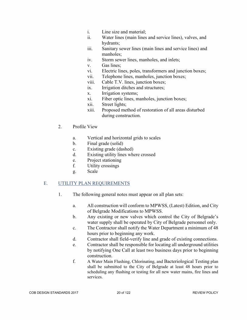
i. Line size and material; ii. Water lines (main lines and service lines), valves, and
hydrants; iii. Sanitary sewer lines (main lines and service lines) and
manholes; iv. Storm sewer lines, manholes, and inlets; v. Gas lines; vi. Electric lines, poles, transformers and junction boxes; vii. Telephone lines, manholes, junction boxes; viii. Cable T.V. lines, junction boxes; ix. Irrigation ditches and structures; x. Irrigation systems; xi. Fiber optic lines, manholes, junction boxes; xii. Street lights;
xiii. Proposed method of restoration of all areas disturbed during construction.
2. Profile View
a. Vertical and horizontal grids to scales b. Final grade (solid) c. Existing grade (dashed) d. Existing utility lines where crossed e. Project stationing f. Utility crossings g. Scale E. UTILITY PLAN REQUIREMENTS
1. The following general notes must appear on all plan sets:
a. All construction will conform to MPWSS, (Latest) Edition, and City
of Belgrade Modifications to MPWSS. b. Any existing or new valves which control the City of Belgrade’s
water supply shall be operated by City of Belgrade personnel only. c. The Contractor shall notify the Water Department a minimum of 48
hours prior to beginning any work. d. Contractor shall field-verify line and grade of existing connections.
e. Contractor shall be responsible for locating all underground utilities by notifying One Call at least two business days prior to beginning construction.
f. A Water Main Flushing, Chlorinating, and Bacteriological Testing plan shall be submitted to the City of Belgrade at least 48 hours prior to scheduling any flushing or testing for all new water mains, fire lines and services.
COB DESIGN STANDARDS 2017 20 of 122 REVIEW POLICY

2. Plans for water facilities shall show the following:
a. Size, type and structural class of proposed new water line(s), including AWWA specifications.
b. Bedding class. c. Type of excavation and backfill.
d. Existing water lines including size and material. e. Proposed valves, fittings, fire hydrants, and service lines, with
stationing. f. Depth of cover from finish grade to proposed water line(s). g. Requirements for pipe deflection, if necessary. h. Type of joint restraint, if required. i. Size of gravity thrust blocks based on calculated design. j. Existing or proposed pressure reducing valves. k. Bench Mark, description and elevation. l. Existing and proposed labeled contours.
3. Plans for sanitary sewer facilities shall show the following:
a. Size, type, and structural class of proposed new sewer line(s), including American Society for Testing and Materials (ASTM) specifications. b. Slope of each proposed pipeline segment. c. Bedding class.
d. Type of excavation and backfill. e. Existing sewer lines and manholes including size, material, field-
verified. f. Invert elevations, and field-verified slopes. g. Proposed manholes with stationing and rim and invert elevations. h. Existing and proposed sewer service lines with size and stationing. i. Existing and proposed cleanouts. j. Bench Mark, description and elevation. k. Existing and proposed labeled contours.
4. Plans for storm sewer facilities shall show the following:
a. Size, type, and structural class of proposed new storm sewer line(s),
including ASTM specifications. b. Slope of each proposed pipeline segment. c. Bedding class. d. Type of excavation and backfill. e. Proposed manholes with stationing and rim and invert elevations. f. Proposed inlets and inlet service lines with stationing and invert
elevations. g. Points of storm water discharge.
COB DESIGN STANDARDS 2017 21 of 122 REVIEW POLICY

h. Bench mark, description and elevation. i. Existing and proposed labeled contours.
F. ROADWAY PLAN REQUIREMENTS 1. Plans for streets or roadways shall show the following: a. Limit of cut or fill.
b. Existing and proposed utilities, including manholes and valves. c. Proposed new construction, including paving width and limits,
curb and gutter, crosspans, sidewalks, and pedestrian ramps. d. Existing and finished grades with existing and proposed labeled
contours and finished grade slopes. e. Vertical and horizontal curves, with curve data: Horizontal curves - R, Δ, L, PC and PT Stationing Vertical curves - K, L, Station of PT’s
f. Profile of centerline. g. Profiles of left and right curb lines, if they are not the same. h. Any required utility adjustments. i. Existing and proposed signs and pavement markings.
j. Existing and proposed storm drainage facilities, including culverts, pipes, inlets, sidewalk chases, ditches and detention/retention ponds, with invert and/or spot elevations.
k. Top of curb elevations at P.C.s, P.T.s, and inlets. l. Existing and proposed street monuments m. Typical roadway section(s), dimensioned and drawn to scale,
showing: - Right-of-way - Backslopes - Sidewalks - Curb and gutter - Pavement thickness - Base and sub-base thickness - Compaction requirements - Transition details from full crown to match line - Cross-slopes
COB DESIGN STANDARDS 2017 22 of 122 REVIEW POLICY
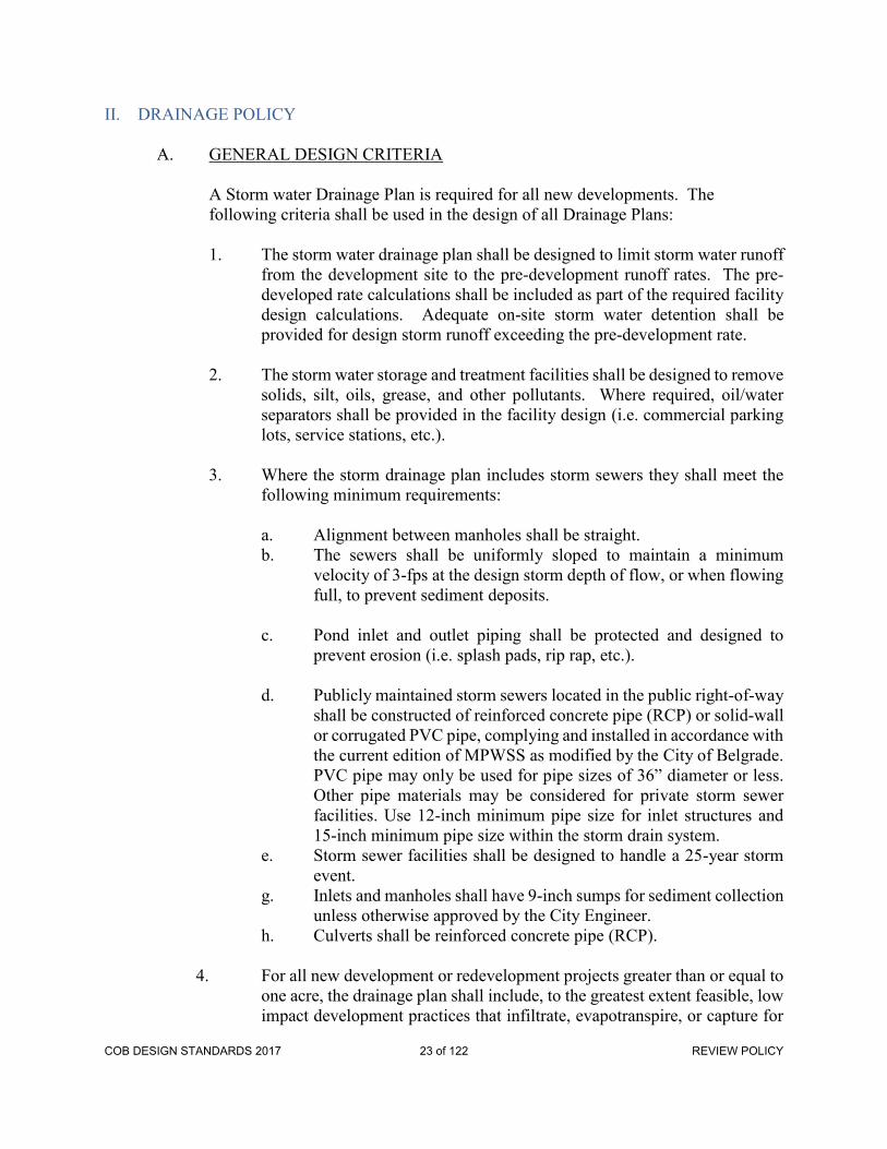
II. DRAINAGE POLICY
A. GENERAL DESIGN CRITERIA
A Storm water Drainage Plan is required for all new developments. The following criteria shall be used in the design of all Drainage Plans:
1. The storm water drainage plan shall be designed to limit storm water runoff
from the development site to the pre-development runoff rates. The pre-developed rate calculations shall be included as part of the required facility design calculations. Adequate on-site storm water detention shall be provided for design storm runoff exceeding the pre-development rate.
2. The storm water storage and treatment facilities shall be designed to remove
solids, silt, oils, grease, and other pollutants. Where required, oil/water separators shall be provided in the facility design (i.e. commercial parking lots, service stations, etc.).
3. Where the storm drainage plan includes storm sewers they shall meet the
following minimum requirements: a. Alignment between manholes shall be straight. b. The sewers shall be uniformly sloped to maintain a minimum
velocity of 3-fps at the design storm depth of flow, or when flowing full, to prevent sediment deposits.
c. Pond inlet and outlet piping shall be protected and designed to
prevent erosion (i.e. splash pads, rip rap, etc.). d. Publicly maintained storm sewers located in the public right-of-way
shall be constructed of reinforced concrete pipe (RCP) or solid-wall or corrugated PVC pipe, complying and installed in accordance with the current edition of MPWSS as modified by the City of Belgrade. PVC pipe may only be used for pipe sizes of 36” diameter or less. Other pipe materials may be considered for private storm sewer facilities. Use 12-inch minimum pipe size for inlet structures and 15-inch minimum pipe size within the storm drain system.
e. Storm sewer facilities shall be designed to handle a 25-year storm event.
g. Inlets and manholes shall have 9-inch sumps for sediment collection unless otherwise approved by the City Engineer.
h. Culverts shall be reinforced concrete pipe (RCP).
4. For all new development or redevelopment projects greater than or equal to one acre, the drainage plan shall include, to the greatest extent feasible, low impact development practices that infiltrate, evapotranspire, or capture for
COB DESIGN STANDARDS 2017 23 of 122 REVIEW POLICY

reuse the runoff generated from the first 0.5 inches of rainfall from a 24-hour storm preceded by 48 hours of no measurable precipitation.
B. STORM DRAINAGE PLAN
A Storm Drainage Plan shall be submitted to the City’s Engineer for all new developments. The Storm Drainage Plan shall be prepared by a Professional Engineer, licensed in the State of Montana. The plan shall include the following:
1. A map or plat showing building site(s), open areas, drainage ways, ditches,
culverts, bridges, storm sewers, inlets, storage ponds, roads, streets, and any other drainage improvements. The map shall also include identification and square foot coverage of the various ground surfaces (i.e. vegetation, gravel, pavement, structures).
2. Topographic contours (one-foot intervals) and sufficient spot elevation
data. 3. Description of the ultimate destination of storm water runoff from the
project and an evaluation of its impact on downslope drainage facilities and water quality.
4. Design calculations determining runoff quantities and storage requirements.
5. A storm drainage facilities maintenance plan. The plan shall: a. Identify ownership of all facilities. b. Establish a schedule for maintenance activities necessary to keep the
system operationally effective. c. Identify the responsible party in charge of the specific maintenance
duties.
6. Details and specifications (including invert and other pertinent elevation information) for all storm drainage improvements, such as storm sewers, manholes, inlets, discharge structures; and retention/detention pond dimensions and volume, side slope, and top, bottom, and maximum water surface elevations.
C. STORAGE/TREATMENT FACILITIES
Detention is the storage and gradual release of runoff to a storm sewer system, waterway, or a soil of high porosity. Detention facilities dampen peak runoff rates and provide treatment of runoff flows. For new development, on-site detention with release rates limited to pre-development runoff rates is required. Complete retention facilities may be provided or required where discharge is not feasible or desirable. Retention ponds shall be
COB DESIGN STANDARDS 2017 24 of 122 REVIEW POLICY

sized based on a 10-year, 2-hour storm intensity. The developer shall be responsible for securing all required DEQ permits for storm water treatment and/or discharge.
1. Detention Basins: Detention basins utilize natural or manmade depressions
or ponds for storage. Release of water is controlled by specially designed outlet structures (Figure A-2 in the Appendix of this Guide).
2. Basin Sizing: A minimum basin area of 145-square feet per 1-cfs release
rate is required for sediment control. The controlling basin volume is determined by subtracting the total basin release volume from the runoff volume at different storm durations. The release rate is equivalent to the pre-development runoff rate at the piping system design frequency (Table 3). The runoff rate is determined at the piping system design frequency using development runoff coefficients. Where the potential for major property damage exists due to downstream flooding and the terrain and availability of land permit the construction of a large detention basin, a 100-year design frequency shall be used for sizing the pond. Basins located in areas accessible to the public shall have a maximum water depth of 1½-feet and for areas protected by a fence a maximum basin depth of 2½- feet. Deep basins designed only for storm water detention shall be placed in remote areas and fenced. A sample problem for sizing detention basins is included in the Appendices of this Policy.
3. Basin Location: Basins serving multiple lots shall be located in common
open space owned by a Homeowners or Property Owners Association. Locating a basin within an easement on a lot will not be permitted unless approved by the governing body. Public park land shall not be used for storm water detention or retention ponds unless approved by the Public Works Director.
4. Additional Requirements: The following additional requirements apply to
the design of above ground earth formed detention basins: a. To prevent short circuiting, basin length shall be at least three times
the width and inlet velocities should be dissipated. b. Basin slopes shall be 3:1 or flatter. c. Vegetative channels shall be utilized wherever possible to remove
wastewater contaminants. d. Basins in floodplains shall have adequate erosion protection on the
embankments. e. Overflows shall be provided to prevent overtopping of dike walls. 5. Retention volumes shall be calculated using the following formulas:
Q = CIA
COB DESIGN STANDARDS 2017 25 of 122 REVIEW POLICY

V = 7200Q (cfs) Where : C = Weighted C Factor I = 0.41 in/hr (see figure I-2, I-3 for 10 year 2 hr storm) A = Area (acres) Q = runoff (cfs) V = volume (cf) D. DISCHARGE STRUCTURES
1. A design detail shall be provided including adequate elevation information. Discharge structures shall be adequately protected from damage. A typical discharge structure is shown in Figure A-2 in the Appendices of this Policy.
2. Orifice or weir calculations shall be provided for controlling the discharge
to the pre-development rate. For discharge structures, the slot width shall be sized using the equation:
Q = CLH3/2
Where: Q = Discharge (cfs) C = Weir Coefficient = 3.33 L = Horizontal Length (feet) H = Head (feet)
3. Failsafe features shall be provided including: a. An emergency free-flowing overflow for rates exceeding design
storm events. b. Discharge piping shall be a minimum of six (6) inches in diameter
for maintenance, and capable of conveying a 25-year storm event. c. Ponds shall be designed so as to avoid long-term standing water in
the pond.
E. ESTIMATION OF RUNOFF
1. GENERAL
The rational method shall be used to determine peak runoff rates with a
COB DESIGN STANDARDS 2017 26 of 122 REVIEW POLICY

slight modification of the method to determine runoff volumes. The basic assumptions that apply to the rational method are:
a. Rainfall is uniformly distributed over the area for the duration of
the storm. b. The peak runoff rate occurs when the duration of the storm equals
the time of concentration. c. The runoff coefficient for a particular watershed is constant for a
similar land use.
The method is based on the Rational Formula with the following limitations: The Rational Method is used for predicting a conservative peak flow rate to determine the required capacity for conveyance facilities. The drainage sub-basin are (A) shall not exceed 25 acres for a single calculation. The time of concentration (Tc) must be computed using the method described below and shall not exceed 100 minutes. It shall be made equal to 6.3 minutes when computed less than 6.3 minutes. The following is the traditional Rational Method equation:
Q = CIRA Q - Peak runoff rate for a storm of rainfall intensity IR (cfs) C - Runoff coefficient (ratio of rainfall that becomes run-off) IR - Average rainfall intensity (in./hr.) A - Drainage area (acres)
2. RUNOFF COEFFICIENTS
The runoff coefficients shown in Table 1 are recommended for design. Coefficients from other engineering texts may be considered for specific applications such as concrete, asphalt, roofs, etc.
Table 1: Runoff Coefficients (C) for use in the Rational Formula
LAND USE RUNOFF COEFFICIENTS (C) Open Land 0.20
COB DESIGN STANDARDS 2017 27 of 122 REVIEW POLICY

Low to Medium Density Residential 0.35 Dense Residential 0.50 Commercial Neighborhood 0.60 Commercial Downtown 0.80 Industrial 0.80 Asphalt, concrete or impervious surface 0.95
3. TIME OF CONCENTRATION
A basic assumption of the rational method is that the peak runoff rate occurs when the duration of the storm equals the time of concentration. The time of concentration is the flow time from the most remote point in the drainage to the point in question. It generally consists of overland flow time and channel flow time. Overland flow time may be estimated from the nomograph in Figure 1. Channel flow time in gutters, ditches, or pipes may be determined by estimating velocities with the Manning equation:
V = 1.486 R2/3 S1/2 n V - Mean velocity (ft/sec.) n - Manning roughness coefficient (typical values in Table 2) R - Hydraulic radius* = cross sectional area wetted perimeter
COB DESIGN STANDARDS 2017 28 of 122 REVIEW POLICY

Figure 1: Time of Concentration (Rational Formula)
COB DESIGN STANDARDS 2017 29 of 122 REVIEW POLICY

Table 2: Manning Equation - Typical "N" Values
Channel Type "n" Factor Open Unlined Channels 0.035 Concrete and RCP Pipe 0.013 Corrugated Steel Pipe 0.024 PVC pipe 0.013
4. STORM INTENSITY
The intensity of the storm is determined from Figure 2 or 3. Duration is assumed to be equal to the time of concentration. The values in Table 3 are the City of Belgrade design frequencies.
Figure 2: Rainfall Intensity- Duration in MinutesCOB DESIGN STANDARDS 2017 30 of 122 REVIEW POLICY

Figure 3: Figure 3: Rainfall Intensity- Duration in Hours
Table 3: Rainfall Frequency for use in the Rational Formula
Land Use Design Rainfall Frequency Open Land 2-year Residential 10-year Commercial or Industrial 10-year
5. RUNOFF RATES AND VOLUMES
The rational formula provides a peak runoff rate which occurs at the time of concentration. The modified rational method approach shall be used to compute runoff volume for storm durations equal to or greater than the time of concentration. This method assumes the maximum runoff rate begins at the time of concentration and continues to the end of the storm. Maximum runoff rates for durations greater than the time of concentration are less than
COB DESIGN STANDARDS 2017 31 of 122 REVIEW POLICY
the peak runoff rate because average storm intensity decreases as duration increases. Total runoff volume is computed by multiplying the duration of the storm by the runoff rate.
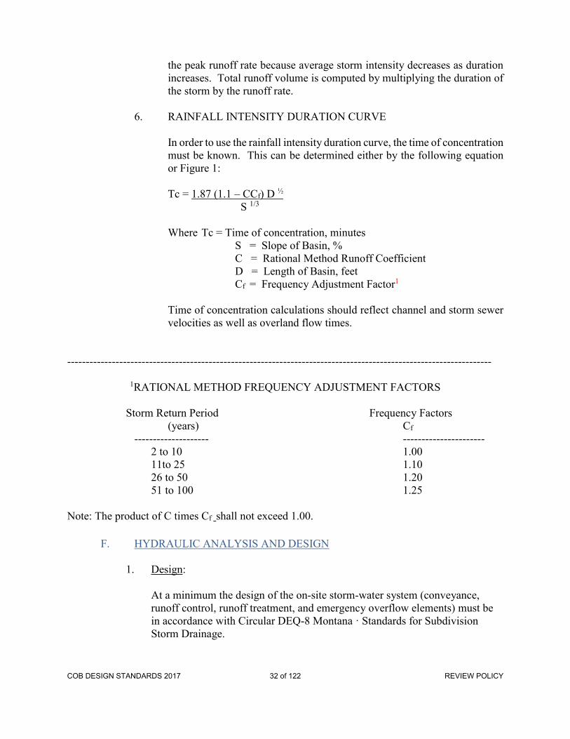
6. RAINFALL INTENSITY DURATION CURVE
In order to use the rainfall intensity duration curve, the time of concentration
must be known. This can be determined either by the following equation or Figure 1:
Tc = 1.87 (1.1 – CCf) D ½ S 1/3
Where Tc = Time of concentration, minutes S = Slope of Basin, % C = Rational Method Runoff Coefficient D = Length of Basin, feet Cf = Frequency Adjustment Factor1
Time of concentration calculations should reflect channel and storm sewer velocities as well as overland flow times.
------------------------------------------------------------------------------------------------------------------
1RATIONAL METHOD FREQUENCY ADJUSTMENT FACTORS
Storm Return Period Frequency Factors (years) Cf -------------------- ---------------------- 2 to 10 1.00 11to 25 1.10 26 to 50 1.20 51 to 100 1.25 Note: The product of C times Cf shall not exceed 1.00.
F. HYDRAULIC ANALYSIS AND DESIGN
1. Design:
At a minimum the design of the on-site storm-water system (conveyance, runoff control, runoff treatment, and emergency overflow elements) must be in accordance with Circular DEQ-8 Montana · Standards for Subdivision Storm Drainage.
COB DESIGN STANDARDS 2017 32 of 122 REVIEW POLICY

The Engineer shall consider drainage system reliability in terms of layout, specification of materials and methods of installation, and the influence of other activities in the area both during and after construction. For any anticipated off-site problems resulting from the development·or re- development, the Engineer/Developer must demonstrate that the proposed project has been designed to mitigate the anticipated problem. The Engineer/Developer, with approval by the City, may arrange with the owners of the other off-site properties to install measures to mitigate existing or anticipated problems. All proposed drainage easements shall be executed by the affected property owners and be recorded prior to approval for construction.
G. CONVEYANCE SYSTEMS
Offsite storm water flows passing through the site shall be conveyed by a hydraulically adequate conveyance system designed in accordance with Circular DEQ-8 Montana Standards for Subdivision Storm Drainage and as modified herein.
1. Conveyance System Setbacks:
Conveyance systems shall not be located: Underneath any structure (e.g. buildings, sheds, decks, rockeries or retaining walls which run parallel to the pipeline, carports, etc.); and Within the 1:1 plane from the bottom edge of the pipe or structure to the finished grade at a building or structure; and Within the 1:1 plane from the bottom edge of the pipe or structure to the property line at finished grade when an easement is not provided on the adjacent property; and . Within one half of the minimum easement width of a structure; and Where such facilities interfere with other underground utilities; and Where allowable design loads would be exceeded.
2. Clearances/Other Utilities:
All clearances listed below are from edge-to-edge of each pipe: Horizontal clearances from storm main shall be as follows: Cable TV, Natural Gas, Power, Sewer, Telephone, and Fiber Optics- 5 Feet minimum
COB DESIGN STANDARDS 2017 33 of 122 REVIEW POLICY

Water- 11 Feet Vertical clearances from storm main shall be as follows: Cable TV, Natural Gas, Power, Sewer, Telephone, and Fiber Optics- 1 Foot Water- 1.5 Feet Where storm sewer pipes cross over or below a water main, one full length of pipe shall be used with the pipes centered for maximum joint separation. The Engineer shall send a letter and preliminary plan to all existing utility company's to: 1) inform them of the new construction, and 2) to request utility as-built information for incorporation into plans. At minimum the following utilities should be contacted: cable television, natural gas, power, sanitary sewer, telephone, water, and telecommunications companies. Submit evidence showing water main crossings account for effects of frost from storm-water piping and that measures have been taken to prevent the freezing of water inside water mains. Avoid crossing other utilities at highly acute angles. The angle measure between utilities shall be between 45 and 90 degrees. For crossings of sanitary sewer pipes Montana DEQ Circulars DEQ-1 and DEQ-2 for water/wastewater systems and Montana Department of Environmental Quality criteria will apply.
3. Open Channel Design Criteria:
Drainage swales shall be located no closer than 10 feet to any structure foundation as measured horizontally from the edge of the swale at the freeboard elevation.
4. Culverts & Bridges:
All culverts and bridges shall conform to Montana Department of Transportation requirements and as modified herein.
5. Storm Drains:
Storm drains shall be provided for all street sections. 6. Private Drainage Systems:
COB DESIGN STANDARDS 2017 34 of 122 REVIEW POLICY
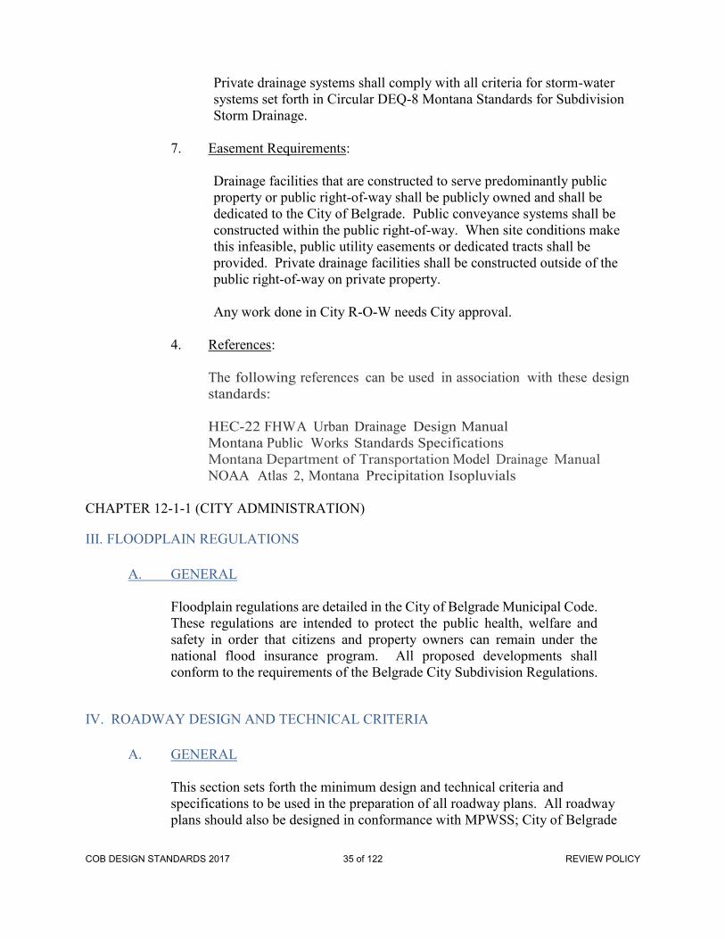
Private drainage systems shall comply with all criteria for storm-water systems set forth in Circular DEQ-8 Montana Standards for Subdivision Storm Drainage.
7. Easement Requirements:
Drainage facilities that are constructed to serve predominantly public property or public right-of-way shall be publicly owned and shall be dedicated to the City of Belgrade. Public conveyance systems shall be constructed within the public right-of-way. When site conditions make this infeasible, public utility easements or dedicated tracts shall be provided. Private drainage facilities shall be constructed outside of the public right-of-way on private property. Any work done in City R-O-W needs City approval.
4. References:
The following references can be used in association with these design standards: HEC-22 FHWA Urban Drainage Design Manual Montana Public Works Standards Specifications Montana Department of Transportation Model Drainage Manual NOAA Atlas 2, Montana Precipitation Isopluvials
CHAPTER 12-1-1 (CITY ADMINISTRATION)
III. FLOODPLAIN REGULATIONS
A. GENERAL
Floodplain regulations are detailed in the City of Belgrade Municipal Code. These regulations are intended to protect the public health, welfare and safety in order that citizens and property owners can remain under the national flood insurance program. All proposed developments shall conform to the requirements of the Belgrade City Subdivision Regulations.
IV. ROADWAY DESIGN AND TECHNICAL CRITERIA
A. GENERAL
This section sets forth the minimum design and technical criteria and specifications to be used in the preparation of all roadway plans. All roadway plans should also be designed in conformance with MPWSS; City of Belgrade
COB DESIGN STANDARDS 2017 35 of 122 REVIEW POLICY

Modifications to MPWSS; Americans With Disabilities Act; and City of Belgrade Sidewalk Policy. Please Note: the City of Belgrade does not allow any public utility construction (i.e. water main or sewer main extensions, street sub-base preparation and paving, etc.) from November 1 through April 1, without the prior written permission of the City of Belgrade.
B. SIDEWALKS, CURBS AND GUTTERS AND DRIVEWAYS
1. Roadway typical sections shall be approved by the City of Belgrade, and
are detailed in Standard Drawing No 02528-03 of the City of Belgrade Modifications to Montana PublicWorks. Roadway typical sections shall conform to conditions of approval for the project. Deviations from these typical sections shall be made on a case-by-case basis and only after a thorough review by the City Engineer.
2. Concrete sidewalks shall be constructed on both sides of all roadways unless otherwise approved by action of City Commission. Sidewalks shall be 6-inches thick across driveways, and 4-inches thick elsewhere. Sidewalk design and construction shall be in accordance with the "City of Belgrade Sidewalk Policy”.
3. All sidewalks shall have a minimum width of five (5) feet, except the
minimum width shall be ten (10) feet in the central business district. 4. Integral curb and gutter shall be used on all roadways unless specifically
approved in writing by the Belgrade City Council. Intergral curb and gutter to be used is detailed in Standard Drawing No 02528-01 of the City of Belgrade Modifications to Montana PublicWorks. Deviations from this standard shall be made on a case-by-case basis and only after a thorough review by the City Engineer.
5. Pedestrian ramps shall be installed at all intersections and at certain mid-
block locations for all new construction or reconstruction of curb and sidewalk. Pedestrian ramps shall be constructed in accordance with City of Belgrade Modifications to Montana PublicWorks Standard Drawings and Americans with Disabilities Act (ADA) requirements. Pedestrian ramps shall be shown at all curb returns or called out by a general note on the development plans. All blocks longer than 500 feet shall require a mid-block crossing unless approved otherwise by the City of Belgrade.
6. Guardrails may be required in certain situations. Guardrails shall be
designed and constructed in accordance with AASHTO Standards or as directed by the City’s Engineer.
COB DESIGN STANDARDS 2017 36 of 122 REVIEW POLICY

7. Drop-curbs for driveways may only be installed with the initial curb construction when the final building locations have been determined. Driveway locations shall conform to the Belgrade City Subdivision Regulations.
8. Curb transitions for curb bulbs where approved by the City of Belgrade shall
be accomplished using 35’ minimum radius curves to achieve the desired pavement narrowing. All curb bulbs shall be adequately marked with flexible roadway delineators and yellow curb paint as necessary. The minimum curb bulb throat width is 24 feet (back of curb to back of curb).
D. ROADWAY DRAINAGE
Drainage systems shall be designed in accordance with these Design Standards and Specifications, Section II, Drainage Policy. Development plans, including a drainage report, for the drainage system are required for concurrent review with, and shall be considered part of roadway design.
1. Crosspans (valley gutters) shall be constructed in accordance with City of
Belgrade Modifications to Montana PublicWorks Standard Drawings. Crosspans are not allowed across collector or arterial roadways, nor are they allowed on roadways with storm sewer systems.
Crosspans may be used parallel with collector or arterial roadways to convey storm runoff across residential roadways. The use of crosspans elsewhere is discouraged, and will only be allowed after all other alternatives have been investigated and written approval from the Belgrade City Council.
2. Inlets:
a. Inlets shall be located to intercept the major curb flow at intervals
sufficient to ensure the depth of flow in the curb line is a maximum of 0.15’ below the top of curb. This will result in a maximum spread width of approximately 9.5’. Inlets should be aligned with lot lines wherever possible.
b. Inlets shall also be installed to intercept cross-pavement flows at
points of transition in super elevation. Due to the presence of pedestrian ramps, inlets are not allowed in the curb return, but will
be located at the tangent points of the curb returns.
c. All inlets within the public right-of-way, or to be maintained by the City of Belgrade, shall be constructed in accordance with City of Belgrade Modifications to Montana PublicWorks Standard Drawings.
COB DESIGN STANDARDS 2017 37 of 122 REVIEW POLICY

3. Cross Slope:
Except at intersections, or where super-elevation is required, roadways shall be level from top of curb to top of curb and shall have a two (2) percent crown as measured from centerline to edge of pavement. Parabolic or curve crowns are not allowed.
Maximum pavement cross slope allowed is five (5) percent at warped intersections, as measured above. In no case shall the pavement cross slope at warped intersections exceed the grade of the through street. When warping side streets at intersections, the crown transition should be completed within 75-feet horizontally for local streets, 100-feet horizontally for collector streets, and 150-feet horizontally for arterial streets. The crown of the through street shall be decreased to 1.5% through intersections, with the crown transitions being accomplished within 100 feet on either side of the intersections. Quarter crowning may be accepted on a case by case basis needing prior approval from the City Engineer.
4. Temporary Erosion Control:
Temporary erosion control is required at the ends of all roadways that are
not completed due to project phasing, subdivision boundaries, etc. Prevention of erosion at the roadway terminus shall be by methods approved by the City of Belgrade.
5. Sidewalk Chases:
a. Storm waters from concentrated points of discharge shall not be
allowed to flow over sidewalks, but shall drain to the roadway by the use of chase sections. The use of sidewalk chases is discouraged, and their use is limited to situations where it is not possible to use standard storm inlets and piping.
b. Chase sections shall not be located within a curb cut of driveway.
Chase sections shall be identified by station and elevation. c. Sidewalk chase sections are to be constructed in accordance with
City of Belgrade Modifications to Montana PublicWorks Standard Drawings.
E. HORIZONTAL ALIGNMENT
1. Turning Radius: All roadways shall intersect at right angles as nearly as
possible. In no case shall the angle of intersection be less than seventy-five degrees (75°).
COB DESIGN STANDARDS 2017 38 of 122 REVIEW POLICY

2. Curb Return Radius: Minimum curb returns shall be as shown in Table 4 of these specifications. A larger radius may be used with the approval of the City Engineer.
3. Design Speed: Design speed shall be as shown in Table 5 of these
specifications. 4. Horizontal Curves: The minimum centerline radius for horizontal curves
shall be as shown in Table 5 of these specifications. Variances from the requirements of Table 5 for local streets only may be considered on a case by case basis.
5. Intersecting Street: Two streets meeting a third street from opposite sides
shall meet at the same point, or their centerlines shall be off-set at least 125 feet.
6. Super-elevation: Super-elevation may be required for arterial roadways
and selected collector roadways. Horizontal curve radius and super-elevation shall be in accordance with the recommendations of AASHTO. Super-elevation shall not be used on local roadways.
7. Spiral Curves: Spiral curves shall not be used on roadways within the
City of Belgrade (State highways excluded) except by written approval of the City of Belgrade.
8. Railroad Crossing: All railroad crossing on streets shall be steel
reinforced rubber or concrete for the full width of the roadway. All required permits and easements shall be secured for railroad crossings.
9. Barricades: Whenever roadways terminate due to project phasing,
subdivision boundaries, etc., barricades shall be required in accordance with the Manual of Uniform Traffic Control Devices (MUTCD) and City Standards.
Table 4: Curb Return Radius at Intersections*
LOCAL COLLECTOR MINOR ARTERIAL MAJOR ARTERIAL LOCAL OR PRIVATE ST. 15' 15' 15' 15' COLLECTOR 15' 25' 25' 25' MINOR ARTERIAL 15' 25' ** ** PRINCIPAL ARTERIAL 15' 25' ** **
COB DESIGN STANDARDS 2017 39 of 122 REVIEW POLICY

* Measured from back of curb ** Per AASHTO Standards
Table 5: Minimum Design Standards for City Streets
STREET TYPE PRINCIPAL
ARTERIAL
MINOR
ARTERIAL
COLLECTOR LOCAL RURAL
Right-of-way width 110’ - 120’3 100’ 90’ 60’ 90’ – 110’3
Centerline radius on curves
1 1 300’ 150’
Tangent length between reverse curves
1 1 100’ 50’
Stopping sight distance 1 1 300’ 200’
Angle at intersection centerline
1 1 >75 >75
Curb radius at intersections
2 2 2 2 N/A
Length of tangent at intersection
1 1 150’ 100’
Back of curb to back of curb 82’ 50’, 63’,
71’3 40’ 38’ - 40’3
Length of cul-de-sac5 N/A N/A N/A 500’ N/A
Outside radius on cul-de-sac right-of-way5
5 5 N/A 60’5 N/A
Grade – maximum 1 1 7% 10%
Grade – minimum 0.7% 0.7% 075% 0.7% 0.7%
Grade within 150 feet of intersecting centerlines
1 1 3% 3% 3%
Design Speed (MPH) 50 45 45 30 45
COB DESIGN STANDARDS 2017 40 of 122 REVIEW POLICY

K Factor (minimum)
Crest
Sag
1
1
1
1
105
65
50
35
105
65
Minimum VCL
Crest
Sag
1
1
1
1
90
70
50
50
90
70
1All design criteria shall meet AASHTO standards. 2See Table 4 3The specific right-of-way and back of curb to back of curb street width will be determined on a case
by case basis through the subdivision review process, and will be based on the specific needs, impacts
and context of the development proposal.
4The rural street standard does not include curb and gutter. The street width is measured from the
edge of pavement to the edge of pavement. 5Cul-de-sacs are generally not allowed. The City’s Engineer may consider and approve the
installation of a cul-de-sac only when necessary due to topography, the presence of critical lands,
access control, adjacency to parks or open space, or similar site constraints. Outside radius of cul-
de-sac right-of-way may be approved at 55’ by the Fire Chief only.
F. VERTICAL ALIGNMENT
Design controls for vertical alignment are shown in Table 5.
COB DESIGN STANDARDS 2017 41 of 122 REVIEW POLICY

1. Permissible Roadway Grades: The minimum allowable grade for any roadway or alley is (0.7) percent. With approval from the City Engineer the minimum grade may be reduced. The maximum allowable grade for any roadway is shown in Table 5 of this Policy. The maximum grade for an alley is subject to the approval of the City’s Engineer.
2. Changing Grades: Continuous grade changes or "roller-coastering" shall
not be permitted. The use of grade breaks, in lieu of vertical curves, is not encouraged. Where the algebraic difference in grade (A) exceeds one percent (1.0%), a vertical curve is to be used.
3. Vertical Curves: All vertical curves shall be symmetrical. Design criteria
for vertical curves are found in Table 5. The minimum grade within a sag (sump) vertical curve is five-tenths (0.50) of a percent. Minimum length of a vertical curve is shown in Table 5. All vertical curves shall be labeled, in the profile, with length of curve (L) and K (=L/A).
4. Intersections: The following additional criteria shall apply at intersections:
a. The grade of the "through" street shall take precedence at
intersections. At intersections of roadways with the same classification, the more important roadway, as determined by the City of Belgrade Public Works Department, shall have this precedence. Warp side streets to match through streets. See Section IV.C. 3 above.
b. The elevation at the point of tangency (PT) of the curb return on the
through street is always set by the grade of the through street in conjunction with normal pavement cross slope.
c. Carrying the crown of the side street into the intersecting through street is not permitted.
d. At an arterial-arterial intersection, a more detailed review of the
entire intersection's drive ability will be done.
5. Curb returns: Minimum fall around curb returns, when turning water, shall be three-tenths (0.3) of a foot for a fifteen (15) foot radius; four-tenths (0.4) of a foot for a twenty (20) foot radius; one-half (0.5) of a foot for a twenty-five (25) foot radius. For all other curb return radii use a grade of 1.25-percent within the return to establish minimum fall when turning water. The maximum fall around a curb return is 3.00-percent. Show and label high point location, elevation and intersection of flow line in plain view if applicable.
6. Connection with Existing Roadways: Connections with existing roadways shall be smooth transitions conforming to normal vertical curve criteria if
the algebraic difference in grade (A) between the existing and proposed COB DESIGN STANDARDS 2017 42 of 122 REVIEW POLICY

grade exceeds one percent (1.0%). When a vertical curve is used to make this transition, it shall be fully accomplished prior to the connection with the existing improvement. Field-verified slope and elevation of existing roadways shall be shown on the plans.
7. Offsite Design and Construction: The design grade, and existing ground at
that design grade, of all roadways that dead end due to project phasing, subdivision boundaries, etc., shall be continued in the same plan and profile as the proposed design for at least three hundred (300) feet or to its intersection with an arterial roadway. This limit shall be extended to six hundred (600) feet when arterial roadways are being designed. If the offsite roadway adjacent to the proposed development is not fully improved, the developer is responsible for the design and construction of a transition with a 4-foot road base shoulder for the safe conveyance of traffic from this improved section to the existing roadway. The following formula shall be applied to the taper or land change necessary for this transition:
Speed Limit 40 MPH or Less L = WS²/60 45 MPH or Greater L = WxS where L = length of transition in feet W = width of offset in feet S = speed limit or 85th percentile speed
The City of Belgrade City Engineer should be consulted for any unusual transition conditions. Grade breaks greater than 1-percent are not allowed when matching existing dirt or gravel streets.
8. The cost of offsite pavement transitions shall be borne by the developer.
G. MEDIAN TREATMENT
Median curbs should be integral curb and gutter (with spill curb) unless otherwise approved. Medians less than eight (8) feet wide should be capped with M-4000 concrete a minimum of three (3) inches thick. Wider medians should be top soiled and seeded with an approved seed mix. The minimum median width is 4 feet. All medians or raised islands should be made clearly visible at night through the use of adequate reflectorization and/or illumination. Flexible delineators shall be placed at the beginning and end of all medians, and at the point of any horizontal alignment change. All median curbs and island curbs shall be painted yellow with epoxy paint.
H. ROADWAY SPECIFICATIONS
Following are the requirements of the minimum roadway surfacing standards:
COB DESIGN STANDARDS 2017 43 of 122 REVIEW POLICY

1. Surfacing:
The pavement thickness design will be based on the current AASHTO Guide for Design of Pavement Structures, or the current Asphalt Institute Manual Series No. 1 (MS-1) for thickness design.
A Pavement Design Report, based upon specific site soil data and design-year traffic loading conditions, prepared by a Professional Engineer, or other qualified professional approved by the City’s Engineer, shall be submitted to the City’s Engineer for approval. The design shall be based on at least a 20-year performance period traffic volume; however, the minimum design lane Equivalent 18,000-lb Single Axle Load (ESAL) used in the pavement design shall not be less than 50,000-ESAL.
The minimum asphalt pavement thickness for any new local roadway shall be three (3) inches. The minimum asphalt pavement thickness for any new City of Belgrade collector or arterial roadway shall be four (4) inches. A minimum of nine (9) inches of high quality untreated aggregate base shall be provided for designs utilizing asphalt pavement over untreated aggregate base. Where full-depth asphalt is designed, an adequate stabilizer lift shall be included, consistent with unpaved roadway design practices, to provide a suitable sub-base capable of withstanding the traffic required for the initial construction of the roadway. The City Engineer may require intersections with roundabouts or traffic circles to be constructed with Portland Cement Concrete surfacing.
2. Flowable Fill:
Flowable fill material shall be used under all street areas when utility trenches are cut through new or existing asphalt. The intent is to protect the integrity of the roadway riding surface and eliminate the potential for roadway failure due to failure of trench backfill material under a roadway. All roadway plans that have a crossing of a utility transverse to the centerline of the roadway shall have a trench detail placed in the plans calling out for placement of flow-able fill complying with the requirements of Section 02225- Flow-able Fill, contained in the Montana Public Works Standards· Specification latest edition. Alternative compaction plans may be considered on a case by case basis by the City Engineer.
1. Right-of-Way Standards:
Typical road-way sections are shown in the City of Belgrade Modifications to Montana PublicWorks. The Right-of-way width that is required to accommodate full build-out of each type of facility are as follows: a) Principal Arterials= 120 feet, b) Minor Arterials= 110 feet, c) Collectors= 80 feet, and d) 60 feet for Local Roads. Although COB DESIGN STANDARDS 2017 44 of 122 REVIEW POLICY
existing roads within the City of Belgrade may not have the necessary right-of-way width based on these standards, it shall be the policy of the City of Belgrade to attain these desired right-of-way widths on all new roadway and development projects. Right-of-way widths less than those listed above will require Belgrade City Council Approval.
I. BRIDGES
1. General
The City of Belgrade requires bridges to be designed in accordance with current Montana Department of Transportation (MDT) standards for "on-system" bridges and the Standard Specifications for Highway Bridges as produced by the American Association of State Highway and Transportation Officials (AASHTO) for "off- system" bridges.
J. UTILITY CORRIDORS
All new utilities shall be placed underground. Except for sewer, water, and storm water; underground utilities, if placed within the public street right-of-way, shall be located between the top back of curbs and the sidewalk. In the event that there is a storm drain utility located underneath one of the curbs all utilities to be located between the sidewalk and curb shall be place on the opposite side of the street unless approved by the City of Belgrade. Such underground facilities shall be installed after the street has been brought to grade and before it is surfaced, to eliminate the necessity for disturbing such surfacing for the connection of individual services. Utility lines shall be designed by a licensed professional engineer or by the utility firms in coordination with the Engineer/Owner. All applicable laws, rules and regulations of appropriate regulatory authority having jurisdiction over such facilities shall be observed. If television, telephone or natural gas is not installed at the time of a development, provisions shall be made for installation of said utilities at a later date, without requiring the cutting of paved roadways.
K. LANDSCAPING REQUIREMENTS
Landscaping requirements shall comply with the requirements as set forth under the City of Belgrade Landscaping Ordinance (See Ordinance 2004-7}The intent of this ordinance is to enhance, conserve and stabilize property values and the roadside environment by encouraging pleasant and attractive surroundings; encourage preservation of existing trees on proposed building sites and along roadways; and contribute to the relief of heat, noise, wind and glare through the proper placement of living plants and trees. A full copy of City of Belgrade Landscaping Ordinance can obtained from the City Clerk at Belgrade City Hall,
COB DESIGN STANDARDS 2017 45 of 122 REVIEW POLICY

91 East Central Street, Belgrade, Montana, 59714_ L. TRANSPORTATION IMPACT STUDIES
Private or public developments which can contribute one hundred (100) or more vehicle trips per days to the City Street System shall have a Traffic Impact Study completed by a professional engineer licensed in the State of Montana. The study shall indicate the expected increase in traffic movements on the existing roadways serving the development and shall determine the existing conditions on roadways to be impacted by the development. The Traffic Impact Study should present an objective technical analysis in a straightforward and logical manner that leads the reader through the analytical process to the resulting conclusions and recommendations. At a minimum, the Report should include the following information:
1.. The study's purpose and objectives.
2. A description of the site and the study area. 3. A description of the existing conditions in the area of the site
(existing roadway geometries, traffic counts, crash analysis, existing intersection level of Service (LOS), existing roadway capacity analysis)_
4. The anticipated nearby land developments and transportation
improvements. 5. Analysis and discussion of trip generation, distribution and
modal splits. 6. The traffic assignment resulting from the proposed development 7. The projection and assignment of future traffic volumes_ 8. An assessment of the traffic impacts attributable to the
development, and 9. Recommendations for site access and transportation
improvements.
COB DESIGN STANDARDS 2017 46 of 122 REVIEW POLICY

Sufficient detail should be provided so that the reviewer is able to follow the path and methodology of the study. All assumptions should be documented and all published reference sources identified.
M. TRAFFIC SIGNAL AND ROUNDABOUT REQUIREMENTS
The City of Belgrade requires that all traffic signal design and plans to be completed in accordance with current Montana Department of Transportation (MDT) standards as contained in Part II (Electrical) of the MDT Traffic Engineering Manual. The MDT traffic Engineering Manual identifies the requirements for determining whether a traffic signal shall be required (See Chapter 12), and goes further to identify specific items which must be contained on any traffic signal design plans. The City of Belgrade requires that all traffic roundabout designs be completed in accordance with all current Montana Department of Transporation (MDT) standards.
N. SIGNING AND PAVEMENT MARKING REQUIREMENTS
1. Street identification signs shall be installed at all new intersections in
accordance with City of Belgrade Modifications to MPWSS. The design Engineer should consider, and the City’s Engineer may require, regulatory traffic control signs and pavement markings in accordance with the MUTCD. Stop signs shall be installed on local streets when they intersect with any City of Belgrade collector or arterial streets.
2. Unless otherwise approved, all transverse markings, words and symbols,
and 8” or larger lane line pavement markings shall be inlaid thermoplastic. or pre-formed plastic tape. All other markings may be either inlaid or preformed thermoplastic or epoxy paint. The materials proposed for all markings shall be specified on the plans.
3. Crosswalk markings should not be used indiscriminately. An engineering
study should be performed before they are installed at locations away from traffic signals or stop signs. Mid-block crosswalks are discouraged for streets less than 500 feet.
a. All marked crosswalks for designated school crossings shall be
longitudinal white bars (“City of Belgrade Type B” style). “School Crossing” signs and “School Advance Warning” signs shall be installed at all designated school crossings.
COB DESIGN STANDARDS 2017 47 of 122 REVIEW POLICY

b. At stop or signal controlled intersections, marked crosswalks shall
be two 8” white lines, 8’ apart typically, installed transverse to traffic and in-line with sidewalks, if any (“City of Belgrade Type A” style).
c. Marked crosswalks at uncontrolled intersections, and all mid-block
crosswalks shall be “Type B”, with “Pedestrian Crossing” signs. “Pedestrian Crossing Advance Warning” signs should be installed.
d. Parking shall be restricted by the use of signs and curb markings
within 50 feet upstream and within 20 feet downstream of all crosswalks, or longer if required by the City Engineer.
e. All crosswalk signs and advance crosswalk signs shall have a
fluorescent yellow green background.
4. All signs shall comply with the “Standard Highway Signs” book (FHWA) and Manual Uniform Traffic Control Devices (MUTCD).
5. Street name signs for publicly-maintained roadways shall consist of white
letters on a green background. Street name signs for privately-maintained roadways shall consist of white letters on a blue background.
O. MONUMENTATION
1. Monuments in monument boxes shall be provided in new or reconstructed
streets at all section corners, quarter corners, and sixteenth corners. P. Street Lighting Requirements:
The design Engineer shall consider the need for roadway lighting in the development of the plans for any new or reconstructed roadways. Illumination shall be provided at all street intersections on collector and arterial streets, and for any roadway with a raised median.
All roadway lighting shall be designed in accordance with the “American National Standard Pracitce for Roadway Lignting” (ANSI/IESNA RP-8-00)
Q. BIKE LANES/PATHS
All bike lanes/paths shall be designed in accordance with the “Guide for the Development of Bicycle Facilities” (AASHTO, latest edition). Bike lanes shall be marked and signed in accordance with the MUTCD.
COB DESIGN STANDARDS 2017 48 of 122 REVIEW POLICY

R. WORK ZONE TRAFFIC CONTROL
A Traffic Control Plan reviewed and approved by the design engineer must be submitted to the City of Belgrade at least seven (7) business days before construction begins for all work within the public right-of-way. The location and description of all traffic control devices must be shown on the Traffic Control Plan. The plan must be approved by the Police Department, Fire Department and Public Works Department prior to beginning construction. If the required traffic control devices are not in place, the Contractor will not be allowed to begin work on the project. All traffic control devices shall be kept in place and maintained in good visible condition throughout the project. The City of Belgrade reserves the right to reject any traffic control device observed to be in inferior condition. Emergency access to the work area shall be maintained at all times. The Manual on Uniform Traffic Control Devices (Millennium Edition) and the Montana Department of Transportation (MDT) Guidelines for Work Zone Safety shall be followed to provide information for the safety of the public. All barricades and obstructions n o t e a s i l y v i s i b l e a t n i gh t shall be protected at night by suitable signal lights which shall be kept illuminated from sunset to sunrise. Barricades shall be of substantial construction and shall be constructed to increase their visibility at night. Suitable warning signs shall be placed and illuminated at night to show in advance where construction, barricades or detours exist. S. ACCESS MANAGEMENT AND CONTROL
It shall be the policy of the City of Belgrade to review all projects for access management and control measures during the review phase of a project. The City reserves the right to mandate certain access control features.
T. TRANSPORTATION DESIGN SPECIFICATIONS
1. General:
The standards for the design of City of Belgrade roads and bridges shall consist of the following references, in addition to items discussed herein:
a. Belgrade City Subdivision Regulations; b. City of Belgrade Zoning Ordinance; c. MDT Structures Manual (Volume I); d. Montana Public Works Standard Specifications latest edition e. Manual on Uniform Traffic Control Devices (Millennium Edition) f. Montana Department of Transportation (MDT) Guidelines for
Work Zone Safety
COB DESIGN STANDARDS 2017 49 of 122 REVIEW POLICY

g. The Americans with Disabilities Act (ADA); h. AASHTO Guide for Design of Pavement Structures i. Asphalt Institute Manual Series No. 1 (MS-1); j. Roadside Design Guide (January 1996) published by the American
Association of State Highway and Transportation Officials (AASHTO) MDT
k . Traffic Engineering Manual l. Standard Specifications for Highway Bridges as produced by the
American Association of State Highway and Transportation Officials (AASHTO)
m. Belgrade Area Transportation Plan, June 2001 Update n. City of Belgrade Modifications to the Montana Public Works
Standard Specifications
2. Construction Plan Requirements for Transportation and Utility Improvements:
The applicant shall submit to the City of Belgrade plans and specifications for street and utility construction. At a minimum, the plans and specifications shall include a vicinity map, a plan and profile, typical sections, roadway cross sections, necessary details for construction, special provisions, reference to applicable Montana Public Works Standard Specifications (MPWSS) and City of Belgrade Modifications to the Montana Public Works Standard Specifications, and any project specific specifications. The submitted plans shall be stamped and signed by a licensed professional engineer in the State of Montana. At a minimum the plan view shall include the road alignment at a scale of not less than one (1) inch to fifty (50) feet showing the following information:
a. Centerline stationing on all intersecting streets, with bearings on centerlines.
b. Curve data on all horizontal curves. c. Right-of-way. d. Relevant topography. e. Existing and proposed utility locations. f. Street names in the new development (if applicable). g. Typical roadway section showing placement of utilities. h. Existing and proposed drainage and water quality
appurtenances. i. Sidewalk locations. j. Floodplain and wetland boundaries (if applicable). k. Signalization and striping/signing.
COB DESIGN STANDARDS 2017 50 of 122 REVIEW POLICY

l. Sufficient topographic data on and adjacent to the site, and m. Any further information as shall be required by the City
Engineer.
At a minimum the profile view shall show the relevant original ground lines using the same stationing as in the plan, control elevations, grade line showing the proposed grades, vertical curves, all bench marks, the vertical datum, and such further information as may be required by the City of Belgrade. For new streets, the relevant original ground lines will show the ground line at centerline at a minimum and also at the edges of the right-of-way if grade differences are significant (or alternatively, surveyed contour lines on the plan view will be acceptable). In addition, top back of curb grades shall be superimposed in the profile view and labeled with the corresponding slope to ensure minimums are either met or exceeded. The profile lines for roads extending to the perimeter of any development shall be extended a minimum three hundred (300) feet beyond the perimeter to include any change in contours that would affect the profile of the extension of the proposed road. Any required construction notes shall be shown or referenced on the plans. The cover sheet of all plans shall include a statement identifying that the Montana Public Works Standard Specifications latest edition will apply to the project. Plan and profile must be shown on the same sheet, with profiles on the bottom half of the sheet. Acceptable sheet size shall be 24 inches by 36 inches. A north arrow shall be shown on each plan view sheet of the plans and adjacent to any other drawing that is not oriented the same as other drawings on the sheet. All detail drawings shall be included in the drawing set. A title block shall appear on each sheet of the plan set and shall be placed in the lower right-hand comer of the sheet, across the bottom edge of the sheet or across the right-hand edge of the sheet. The title block shall include the name of the project, the engineering firm, the sheet title and the owner.
3. Transportation Design Specifications:
The typical roadway section shall be as shown in the City of Belgrade Modifications to Montana PublicWorks standard drawings. The roadway section used shall be detailed on the construction plans submitted for each new roadway or improvement to an existing roadway. Any deviations from the standard roadway typical section will require approval
COB DESIGN STANDARDS 2017 51 of 122 REVIEW POLICY

from the Belgrade City Council. The typical section shall show the width of the right-of-way, width of roadway, type and compacted depth of surfacing and paving materials, and such other dimensions as may be necessary or required. The location and width of sidewalks, walkways, curbs or curb and gutter shall also be shown. Alternate surface treatments may only be used upon approval of the Belgrade City Council. The applicant shall supply the City of Belgrade with specifications for materials and application rates as part of the approval process.
4. Transportation Construction Specifications:
No construction shall begin until plans have been approved by the City of Belgrade. Temporary and permanent barricades shall conform to the standards described in Section 6F of the Manual on Uniform Traffic Control Devices (MUTCD) Millennium Edition. Type I or Type II barricades shall be used when traffic flow is maintained through the area being constructed/reconstructed. Type Ill barricades shall be used when roadways and/or proposed future roadways are closed to traffic. Type Ill barricades shall extend completely across the roadway or from curb to curb. Where provision must be made for access of equipment and authorized vehicles, the Type III barricades may be provided with movable sections that can be closed when work is not in progress, or with indirect openings that will discourage public entry. When job site access is provided through the Type I barricades, the Contractor/Owner shall assure proper closure at the end of each working day.
In the general case, Type Ill permanent barricades shall be installed to close arterials or other through streets hazardous to traffic. They shall also be used to close off lanes where tapers are not sufficiently delineated.
Type III barricades shall be used at the end of a local street that end abruptly without cul-de-sac bulb or on temporarily stubbed off streets. Each barricade shall be used together with an end-of-road marker and shall be illuminated from dusk till dawn. Barricades on dead-end streets that may be extended in the future will have a sign placed upon them, as approved by the City of Belgrade.
V. UTILITY DESIGN CRITERIA
A. WATER DISTRIBUTION LINES DESIGN CRITERIA
COB DESIGN STANDARDS 2017 52 of 122 REVIEW POLICY

1. Design Criteria:
All additions or modifications to the City of Belgrade water system will be designed in accordance with the criteria set forth in this and other sections of this Policy as approved by the City’s Engineer. All additions to the water system will be designed and installed in accordance with the Montana Department of Environemental Quality (DEQ) Circular No. 1; MPWSS (latest); City of Belgrade Water Facility Plan; City of Belgrade Modifications to MPWSS; and CITY OF BELGRADE Fire Service Line Standard.
2. Master Water Plan Water Model:
A master water plan water model shall be submitted for each subdivision or other major development prior to approval of any portion of the water system. An overall plan of the development, including all areas outside of the study area which would naturally be served through the study area shall be submitted.
3. Design Report:
A design report prepared by a professional engineer licensed in the State of Montana demonstrating compliance with these requirements shall be submitted to and approved by the City of Belgrade with the plans and specifications for any new development. Design parameters and the critical conditions shall be shown on an overall plan of the study area. An overall plan of the development, including all areas outside of the study area which would naturally be served through the study area shall be included.
4. Water Service Area – Expansion:
The official water service area for the city is that area of the city within the boundaries of the city and currently served by city water, any areas and any subsequently approved amendments thereto.
Applications for water service area enlargements·shall be made on forms prescribed by the City Manager and shall be accompanied by all documentation requested by theCity of Belgrade.
5. Conditions for Service Area Expansion:
The following conditions shall be met prior to making application for enlargement of the service area. The property at the time the application is filed shall be:
COB DESIGN STANDARDS 2017 53 of 122 REVIEW POLICY

Contiguous to the boundary of the service area as the same exists;
a. Entirely within the city's full service, urban planning area;
b. Entirely within the city's facilities planning area. 6. Annexation Requirements:
All properties to be included within the service area shall be annexed or an attempt to annexation shall be made first and before any service area enlargement applications may be considered. Further, that whenever possible the property being considered for inclusion in the service areas shall be annexed to the city rather than accepting waivers of the property owner's right to protest annexation of said property to the city. Waivers may be accepted by the city in its sole discretion only in those particular cases where good and sufficient cause is shown and a hardship would result if waivers were not accepted. A prospective applicant shall first petition the city to annex the property involved prior to submission of a service area enlargement application. The city commission shall then consider such petition. Any waivers must be in legal form as approved by the city attorney; be recorded with the county clerk and recorder of Gallatin County, Montana; run with the land, and shall be signed by owners of the majority of the land area and by a majority of the landowners of the area to be considered by inclusion in the water or wastewater service area. The city manager shall notify in writing the prospective applicant of the approval or denial of annexation or of the right to file waivers or both.
The city manager shall notify in writing the prospective applicant of the approval or denial of annexation or of the right to file waivers or both. The city manager shall also notify the prospective applicant of the approval or denial of enlargement of the service area. If approved the applicant shall be notified as to when the requirements set forth in this section have been satisfactorily completed and authorize said applicant to proceed with the service area enlargement application.
7. Main Size: The water distribution system shall be designed to meet the
maximum demand plus fire flow and the peak hour demand. The design shall be based on a maximum hour to average day ratio indicated in the latest version of the Belgrade Water Master Plan 3.19:1 (2017 version) and maximum day to average day ratio of 2.31:1 for an average daily usage of 102-gallons per day per person (2017 version), plus fire flow demand as
COB DESIGN STANDARDS 2017 54 of 122 REVIEW POLICY

determined by ISO (Insurance Services Office) criteria. A “C” Factor of 130 shall be used in modeling system designs. The working residual water pressure shall not be less than 20-psi at any point in the water distribution system under maximum day plus fire flow. The velocity of the water in the system shall not exceed 10-feet per second through a public main line. The minimum diameter for any new main is 8-inch, unless specific approval in writing is obtained from the City of Belgrade for smaller diameters. Larger diameters shall be required in order to maintain the minimum pressure requirements of Montana Department of Environemental Quality Circular DEQ-1 “Standards for Water Works.”
8. Design Considerations:
Hydraulic Analysis-The design of all water mains shall be based on a hydraulic analysis considering flow demands and pressure requirements. The main must be designed to maintain a minimum normal working pressure of 45 psi, and maintain an absolute minimum pressure o f 20 psi under all flow conditions. Maximum normal working pressures shall not exceed 85 psi.
Fireflows - All mains shall be designed to provide adequate fire flows unless specifically waived by the City of Belgrade Public Works Department. The amount of fire flow required·for structures shall be based on the 2012 International Fire Code. Non-structural utilization of an area shall have the fire flow requirements as determined by the City of Belgrade Fire Chief. The minimum fire flow for any structure shall be 1000 gallons per minute, with a minimum of twenty pounds per square inch residual pressure at the hydrant during flow.
9. Water Main Material:
All water main pipe shall be DR 14 Class 200 PVC pressure pipe meeting AWWA C900 or ductile iron Class 51 wall thickness meeting AWWA C151.
. All fittings used shall be made of ductile iron. Acrylonitrile butadiene (NBR) gaskets are required for water main installations in areas of hydrocarbon contamination.
Fittings - All water main fittings, including tees, crosses, caps, plugs, reducers and elbows equal to or greater than 22 1/20 shall be restrained using standard mechanical joints with concrete thrust blocks. In leiu of using thrust blocks, where appropriate, mechanical joint restraints shall be "Megalug", Uniflange or equal may be used. All mechanical joint restraint shall be provided in accordance with Montana Public Works Standard Specifications and the City of Belgrade Modifications to Montana Public Works Standard Specifications.
COB DESIGN STANDARDS 2017 55 of 122 REVIEW POLICY
10. Installation:
Please Note: In order to isolate sections of the existing water system to allow for new construction, it may be necessary to operate existing system valves. The City Water Department shall be notified when existing valves must be operated and shall undertake those operations. Due to the variability of age and condition of existing valves it is possible that the City’s valve will not completely close. The design engineer should consider installing new valves at the connection points to all new mains and existing mains. The minimum cover for all water mains from top of pipe to final finished grade shall be six and one-half (61/2) feet unless otherwise approved by the Public Works Director/City Engineer. All water main piping, fittings, valves, etc. shall be encased in polyethylene wrap with a minimum thickness of 8 mils. All encasement shall be in accordance with AWWA C-105 Standards.
11. Main Extensions: All main extensions shall be looped, where possible. All dead end 8” mains shall end with a fire hydrant or 2” blowoff. Larger diameter dead end mains shall end with a fire hydrant. Permanent dead-end mains shall not exceed 500-feet long. Temporary dead-end mains scheduled for future extension may end with a blow-off in lieu of a fire hydrant with approval from the City Engineer.
Any extension of an existing City water main must be extended through the
entire frontage length of the property to be served. Main extentsions shall include all valves, hydrants and appurtenances deemed necessary by the City. The Director of Public Works may require that public mains be connected, extended, or looped in addition to the proposed extension to provide an adequante and functional water supply.
12. Sewer Line Crossings:
A minimum of 18-inches vertical separation is required when a water main crosses above or below a sanitary sewer, measured outside to outside of pipe. Please refer to MPWSS Drawing 02713-2 for further information on sewer line crossings. Less than 18-inches vertical separation may be allowed when a gravity sewer at the crossing is made from a single 20-foot length of AWWA pressure pipe and the crossing is approximately 90°. Specific authorization from the Montana Department of Environmental Quality and the City of Belgrade Public Works Department is required for a
COB DESIGN STANDARDS 2017 56 of 122 REVIEW POLICY

vertical separation of less than 18-inches. · No exception of the minimum 18-inch vertical separation requirement is permitted when the sewage pipe is a force main.
Unless specifically authorized by the Montana Department of
Environmental Quality and the City of Belgrade Public Works Department, a minimum of 11-feet horizontal separation is required when a water main and sanitary sewer are installed in parallel.
13. Tapping City Water:
The City of Belgrade Water Department shall witness all water main taps. Preparations for exposing the water main and preparing the water main for tapping, as well as scheduling for the City to witness the tap are all responsibilities of the contractor. Water main taps shall only be made by a plumber licensed in the State of Montana. The City of Belgrade Water Department can be contacted at (406) 388-3760. Any person desiring to make connection to the City's water or sewer mains must make application in writing, and pay for the cost of tapping.
14. Water Service Lines:
a. A water line is designated as either a service line or water main based on its use, not its size. Generally, a line serving a single building or facility is considered a service line; a line serving more than one building, or intended to serve more than one building or facility is generally designated a water main. The standard sizes of service lines are 3/4-, 1-, 1½-, 2-, 4-, 6-, or 8-inch. The minimum size of a fire service line is 1-inch. Plans and specifications prepared by a Professional Engineer licensed in the State of Montana shall be submitted for 4-inch and larger service lines.
b. For service pipe sizes less than 4-inch service pipe shall be type “K”
annealed copper meeting AWWA Standard C800 or Polyethylene Pressure Pipe meeting AWWA Specification C901. Polyethylene services shall be a minimum size of 1” Class 200 with a DR of 7. Polyethylene pipe to be Phillips, Drisco, Ultraline 5100 or approve equal. Service pipe that is larger than 4-inch shall be PVC or ductile iron. Plans and specifications prepared by a Professional Engineer licensed in the State of Montana shall be submitted for 4-inch and larger service lines.
COB DESIGN STANDARDS 2017 57 of 122 REVIEW POLICY

c. The service stubs shall be installed in accordance with the City of Belgrade Standard Drawings for service lines. The service line stubs shall be installed at the center of each lot unless otherwise approved by the Public Works Director or City Engineer.
d. No service line shall be extended into a building until an
"Application for Service" has been completed and a Plumbing Permit has been obtained from the City of Belgrade Building Department.
e. Backflow prevention devices as required by the City of Belgrade
Modifications to the Montana Public Works Standard Specifications shall be installed on each fire and domestic service line.
f. All service connections shall be uniform size from the service line
tap to the building structure or structures unless otherwise approved or required by the Public Works Director or City Engineer. The Public Works Department shall reserve the right to require a larger service connection to any building, structure or development if the water requirements when calculated by the fixture unit method, as specified in the Uniform Plumbing Code, cause the service line velocity to exceed ten (10) feet per second. Each service line and meter shall supply a specific building.
g. All service line stubs shall be sized to adequately serve the
maximum anticipated demand for the property being served. h. The Public Works Director or City Engineer may require the
termination of any existing service stubs (either for domestic or fire service) that are not utilized for service upon the development of the lot. Lines to be terminated shall be capped or plugged at the main, and any curb boxes or valve boxes on the line shall be removed.
15. Curb Stops and Boxes:
All curb stops shall be installed in accordance with the latest version of the MPWSS and the City of Belgrade Modifications to MPWSS.
16. Meters:
All meters shall remain the property of the City and may be removed at the discretion of the City of Belgrade Public Works Director. Water meters costs shall be paid to the City by the water user and shall be installed by the water user under the City's direction. The manner of installation of said meters shall be approved by the City of Belgrade prior to installation.
COB DESIGN STANDARDS 2017 58 of 122 REVIEW POLICY

All water meter installations require installation of a SENSUS compatible "radio read" transmitter module, which will be paid for by the property Owner, and shall register water usage in thousands of gallons. Meters will be installed inside the building a licensed pluber on all service lines except for fire service lines. Meter pits shall not be used unless specifically approved by the Public Works Director or City Engineer.
17. Backflow Prevention Device:
Backflow prevention devices shall be installed on each fire and domestic service line, unless otherwise approved in writing by the City of Belgrade.
18. Valves: All water valves installed in the City of Belgrade shall meet or exceed the
requirements of ANSI/AWWA C550 and shall be certified to ANSI/NSF 61. All interior and exterior valve surfaces shall be Fusion Epoxy Coated. The epoxy coating shall meet or exceed the requirements of ANSI/AWWA C550. All valves shall have a Non-Rising Stem (NRS) design, with a 2 inch square wrench nut, and shall open in the counter-clockwise direction.
Valve locations shall be determined and installed in accordance with the
following, unless otherwise approved or required by the City of Belgrade: a. All connections to an existing water main will begin with a new
valve.
b. Valves shall be located at not more than 500-foot intervals in commercial districts and at not more than one block or 800-foot intervals in other districts.
c. Every leg of a main intersection shall have a valve.
d. Valves shall be placed so that main shut-downs can be accomplished with only one fire hydrant being out of service at a time.
e. All gate valves shall conform to AWWA C-509 Standards and shall
open COUNTER-CLOCKWISE. f. All butterfly valves shall conform to AWWA C-504 Standards and
shall open COUNTER-CLOCKWISE. All valves larger than 14”
COB DESIGN STANDARDS 2017 59 of 122 REVIEW POLICY

shall be butterfly valves.
COB DESIGN STANDARDS 2017 60 of 122 REVIEW POLICY

19. Hydrants: All hydrants installed in the City of Belgrade shall meet the requirements of ANSI/AWWA C-502 Standards and physically consists of two hose nozzles, one pumper nozzle, and a 5 ¼ inch main valve opening. Hydrant models shall conform to the requirements of the City of Belgrade Modifications to MPWSS.
Hydrants shall be located at each street intersection and at intermediate
points so that hydrants are spaced no further apart than one standard City block, which is 400 feet. The Fire Chief reserves the right to require additional fire hydrants if the demand of the structure(s) requires more flow than the minimum spacing provides, depending on the area being served. Mid-block hydrants shall be installed in line with property lot lines.
All hydrants shall be painted OSHA red above the ground line. All hydrants
shall be equipped with a #4 pentagon (1¼”) operating stem nut and shall open in a COUNTER-CLOCKWISE direction. The direction of the opening shall be indicated by a permanent arrow on the hydrant top.
All hydrants shall be designed for a minimum 7-foot bury depth. Hydrants
with less than 7-foot bury depth will need approval from the Public Works Director or City Engineer. All hydrant safety flanges shall be set at 1.5 inches to 3 inches above the finished grade. The hydrant auxiliary valve shall be located in the street.
Please Note: All proposed hydrant locations shall be reviewed and
approved by the City of Belgrade Fire Department prior to installation.
20. Water Vaults: All underground vaults and manholes associated with the City’s water system shall be constructed of pre-cast concrete sections meeting ASTM C-478 or ASTM C-858. All water vault manhole covers shall have the word “water” cast into the top surface.
21. Air Relief: Air relief shall be provided at all high points in the line where
air can accumulate by means of hydrants, services, or air relief valves. Hydrants are the perfered means for air relief. Prior approval from the Public Works Director or the City Engineer needs to be acquired prior to designing a air relief valve.
22. Pressure Reducing Valves: City of Belgrade Public Works Director or City
Engineer may require pressure reducing valves to be installed when the anticipated average-day line pressure exceeds 80 psi.
23. Thrust Restraint: All thrust restraint shall be designed to withstand the test pressure or the working pressure plus surge allowance, whichever is larger. Adequate factors of safety shall be employed in the design.
B. SANITARY SEWER SYSTEM DESIGN CRITERIA
COB DESIGN STANDARDS 2017 61 of 122 REVIEW POLICY

1. All additions or modifications to the City of Belgrade sanitary sewer system will be designed in accordance with the criteria set forth in this and other sections of this Guide as approved by the City’s Engineer. All additions to the sewer system will be designed and installed in accordance with DEQ Circular No. 2; MPWSS; City of Belgrade Modifications to MPWSS, the Uniform Plumbing Code and the City of Belgrade Wastewater System Needs Analysis.
2. A design report prepared by a professional engineer licensed in the State of
Montana demonstrating compliance with these requirements shall be submitted to and approved by the City of Belgrade with the plans and specifications for any new development. Design parameters and the critical conditions shall be shown on an overall plan of the study area. An overall plan of the development, including all areas outside of the study area which would naturally be served through the study area shall be included.
3. New sewer lines shall be sized to flow at no more than 75-percent of full
capacity at peak hour conditions upon the full build-out of the development. The effects of the proposed development's sewer loading on existing downstream sewer lines shall be analyzed.
4. New sanitary sewer lines to serve residential areas shall be designed to
accommodate an average daily flow rate of 2.5 people per dwelling unit and 90-gallons per capita per day as designated by the latest City of Belgrade Wastewater Master Plan.. An infiltration rate of 50-gallons/acre/day shall be added to all flow calculations when designing new sewers.
5. Gravity sewer main piping shall consist of any of the following materials:
PVC meeting ASTM D 3034, SDR 35 (8” to 15”) PVC meeting ASTM D 679, SDR 26 or ASTM D F794 (18” and larger) Concrete meeting ASTM C14, C76 or C655 Other pipe materials specifically approved by the City of Belgrade Pressure sewer piping (force mains) shall consist of PVC Pressure Pipe,
ASTM 2241, Class 200 SDR 21.
6. A Manning’s friction factor of 0.013 shall be used in designing new sewers. A peaking factor shall be calculated for each pipe segment based on the following formula;
Qmax 18 + P1/2 -------- = ----------- (P = Population/thousands) Qave 4 + P1/2
For non-residential flows an equivalent population shall be calculated for use in the peaking factor formula.
COB DESIGN STANDARDS 2017 62 of 122 REVIEW POLICY

Table 6: Residential Zoning Densities
TABLE 6
RESIDENTIAL ZONING DENSITIES
ZONE DESCRIPTION POPULATION DENSITY (People/Acre)
R-1
Residential- Single Family
16.0 R-2 Residential- Single Family- Medium Density 16.0 R-2-D Residential – One & Two Family 16.0 R-2-M · Residential- Single Family & Manufactured Home 16.0 R-3 Residential - Medium Density District 26.0 R-4 Residential- Apartment District 51.0 RS Residential - Suburban District 12.0 RS-M Residential - Suburban District - Manufactured Home 25.4
AS Agricultural - Suburban District 18.4
Table 7: Business and Manufacturing Flow Rates
TABLE 7
BUSINESS AND MANUFACTURING FLOW RATES
ZONE DESCRIPTION CLASSIFICATION
FLOW *EQUIVALENT POP. (Gallons/Day/Person) (People/Acre)
M-1 Commercial - Light Manufacturing 140 5.0 M-1 Manufacturing & Industrial District 140 5.0 B-1 Neighborhood Business District 140 10.0 B-2 Highway Business District 140 10.0 B-3 Central Business District 140 10.0 BP Business Park nla n/a BP-10 Business Park nla nla PL-1 Public Lands & Institutions nla nla
*To be used for peaking factor computation. Based on 140 gal/capita/day
COB DESIGN STANDARDS 2017 63 of 122 REVIEW POLICY

9. Barrel Size: The alignment and number of pipes into the manhole will determine the barrel size for the size of pipe used. All 48-inch manholes will have eccentric cone top sections if total manhole height is greater than six feet. All other manholes will have flat tops. All drop manholes shall be “inside drop” with a minimum barrel diameter of 60-inch. The internal diameter of the manhole barrel shall be typically as follows:
SANITARY SEWER
PIPE SIZE BARREL SIZE 12" or less 48" 15" to 27" 60"
30" to 48" 72"
Manholes larger than seventy-two (72) inches may be allowed with specific approval by the City of Belgrade or the City’s Engineer.
10. Manhole Channels: All manholes shall have full-depth channels. When a
smaller main is being connected to a larger main at a manhole, the manhole inverts shall be set so that the 8/10 depth of flow of each main is equal in elevation. The minimum drop across a manhole (invert in to invert out) is 0.2’ (cut-in manholes excluded).
11. Sanitary Sewer Mains: The minimum diameter of a sewer main is 8-inches. Main lines shall be sized for design flow, not available slope. PVC pipe shall be used for all gravity flow main lines unless other materials are specifically approved.
12. Sanitary Sewer Services: The minimum diameter of a service is 4-inch. Services shall connect to the main with in-line gasketed wyes. The service line stub, from the main to the property line or easement line, shall be installed with a maximum slope of 1/2-inch per foot. The minimum slope of a 4-inch service line stub is 1/4-inch per foot. Upon approval from the Public Works Director or City Engineer, a 4” sewer service line can be installed at 1/8-inch per foot. The minimum slope of a 6-inch service line stub is 1/8-inch per foot. Sewer service line stubs will typically be installed 15-feet from the downstream lot line. Services are to be installed perpendicular to the main.
Each building shall have a separate service line from the building to the
sewer main, with the following exception: Accessory Dwelling Units (ADUs) may share sewer service with the service from the primary dwelling unit on the lot, provided that the service is television inspected at the owner’s expense, and the Public Works Director or City Engineer determines that the service is in an acceptable condition for shared use.
13. Materials:
COB DESIGN STANDARDS 2017 64 of 122 REVIEW POLICY

Gravity Sewer Service Piping:Gravity sewer service piping shall consist of the following materials for the following situations:
PVC meeting ASTM D 3034, SDR 35- Solvent Weld or SBR Gasket Joint for normal installations
PVC Schedule 40 or Cement Lined Ductile Iron for installations within 2-feet of a building foundation
PVC Schedule 40 for water main or water service crossing
PVC Schedule 40 with acrylonitrile butadiene (NBR) gaskets for installations in areas of hydrocarbon contamination.
Pressure Sewer Service Piping:Pressure sewer service lines shall consist of PVC Pressure Pipe, meeting ASTM 2241, Class 200, SDR 21.
14. Installation:
All sanitary sewer service lines must be so arranged that the discharge from each separately owned house or premises is a separate service line and the owner of each house or premises is liable for the charges for the wastewater service provided by the city to that owner's house or premises. One service line may service multiple units that are separately owned provided the common service line is owned, operated and under the control of a single person or entity who is responsible for the maintenance of the service line, including the connection with the main and it meets the classification of a service as outlined by DEQ-2.
All sewer service lines shall be installed in accordance with the City of Belgrade Modifications to the MPWSS with a minimum of four (4’) feet of cover from the top of service pipe to final finished grade.
15. Tapping City Sewer:
Any person desiring to make connection to the City's water or sewer mains must make application in writing, and pay for the cost of tapping. All applications for service connection to the city's wastewater system must be made at the City Hall Building, 91 East Central Street, Belgrade, Montana 59714. Every such application must be made by the owner of the property to be served or the owner's authorized agent and must include the nature of wastewater to be discharged into the-system.
16. Metering When Not On City Water:
For City sewer users who do not use the city water system or whose water
COB DESIGN STANDARDS 2017 65 of 122 REVIEW POLICY

consumption or wastewater discharge is not otherwise metered, the City of Belgrade shall require the installation of a suitable metering device in order to determine an equitable charge for sewer services.
17. Access Roads: A 12'-wide all-weather gravel access road, with turn-arounds if needed,
shall be constructed to provide access to all sanitary sewer manholes not located within a paved public or private street or parking lot.
18. Cut-in Manholes: Pre-cast manhole bases are preferred for cut-in manholes. Poured-in-place
cut-in manholes may be used if approved by the Public Works Director or City Engineer.
C. STORM SEWERS
1. Materials: RCP (reinforced concrete pipe) or PVC pipe may be used, however PVC
pipe may only be used for pipes sized 36” diameter and smaller. PVC pipe shall have a minimum stiffness of 46 PSI. Structural strength shall withstand HS-20 design load. If PVC pipe is used, all pipe exposed to sunlight shall be protected with concrete headwalls or prefabricated end sections in accordance with MPWSS Section 02725.
2. Minimum Sizes:
Storm sewer mains shall not be less than 15-inch diameter. Privately owned
storm sewers may be smaller, but shall still be designed in accordance with section C.5 below.
3. Manhole Spacing and Size:
Storm Sewer Pipe Diameter or Maximum Manhole
Vertical Rise Spacing (Ft.) 12" - 36" 400
42" - 60" 500 66" and Larger 750
Storm Sewer Pipe Diameter Barrel Size* (Ft.)
15" - 18" 4 20" - 28" 5
30" - 48" 6
COB DESIGN STANDARDS 2017 66 of 122 REVIEW POLICY

* Multiple pipe penetrations may require larger manhole barrels
4. Storm Inlets a. Publicly owned storm inlets shall comply with the latest addition of
the applicable standard drawing in the City of Belgrade Modifications to MPWSS. Where inadequate overflow paths are provided, inlets must be oversized 50-percent to accommodate plugging.
b. The size of outlet pipes from storm water inlets shall be based upon
the design capacity of the inlet, but shall not be less than 12-inches in diameter. The outlet pipes shall connect to the storm sewer main with a manhole.
c. Computations for storm sewer design and storm inlet designs shall
be submitted with the plans and specifications. Adequate details of inlets, manholes and other appurtenances shall be included in the overall drainage plan submitted for approval.
d. Combination manhole/inlets may be used where approved as
detailed in the City of Belgrade Modifications to MPWSS. 5. Hydraulic Design
All storm sewer facilities, including inlets and sidewalk chases, shall be designed to convey the 10 year storm event with no surcharging (i.e. pipe full with no head). Inlets and sidewalk chases shall be designed to convey the 10 year storm flow with a maximum water surface elevation of 0.15’ below the top of curb. Drainage reports shall include hydraulic grade line calculations including losses from friction and transitions. Approved erosion control shall be designed and installed at all outlets.
6. Alignment a. Manholes are required wherever there is change in size, direction,
elevation, grade or at sewer main junctions. b. The minimum vertical clearance between a potable water main and
a storm sewer main is 1.5-feet. The minimum horizontal clearance between a potable water main and a storm sewer main is 11-feet.
c. Horizontal alignment between manholes shall be straight.
COB DESIGN STANDARDS 2017 67 of 122 REVIEW POLICY

7. Culverts
a. A culvert is considered to be any structure which connects two open
channels. The culvert is to be designed to convey the 25-year frequency flow of the tributary drainage basin. The headwater depth will be limited by upstream conditions, but in no case shall exceed 1.5 times the culvert diameter. Excessive ponding above culvert entrances will not be acceptable if damage appears likely to surrounding property or to the roadway.
b. Culverts shall be designed with an emergency overflow path. The
emergency overflow capacity shall be 100-percent of the whole culvert for the major storm for culverts with area less than twenty square feet and for culverts with area greater than or equal twenty square feet, the overflow capacity shall be 100-percent of the capacity provided by the first twenty square feet plus 20-percent of the capacity provided for the additional area as established by the formula:
% overflow = (110%) 20+ (A-20)*0.20 , A where "A" is the area of the culvert opening.
If the culvert is located in a low point in the road the required overflow capacity can be provided by overtopping the road, as long as this does not result in more than 50 feet of street being flooded. Where the culvert is not in a low point, or where more
than 50 feet will be flooded, the overflow capacity shall be provided by either increasing the culvert size, or additional culverts.
8. Culvert Hydraulics a. Inlet and Outlet Structures: The culvert including inlet and outlet
structures shall convey water, sediment and debris at all stages of flow.
b. End Treatment: Flared end sections or headwalls with wingwalls
are required. Inlets are to be designed to minimize head losses. Approved erosion control is to be provided at all culvert outlets and inlets. Trash racks shall be provided, at the upstream end, for all culverts.
c. Slopes: Culvert slopes shall prevent silting, yet avoid excessive
COB DESIGN STANDARDS 2017 68 of 122 REVIEW POLICY

velocities. Generally, the minimum culvert slope is 0.50-percent. Minimum barrel velocity is 3-fps and maximum is 12-fps.
d. Hydraulic Analysis: Inlet and outlet control conditions shall be
analyzed. Calculations shall be submitted with the design report.
e. Minimum Size: Culverts crossing a roadway shall not be smaller than 24-inch equivalent diameter. Driveway approach culverts shall not be smaller than 15-inch equivalent diameter. Culvert length shall be adequate to provide back slopes of 4:1 or less from pipe inverts to finished street section, including existing or future sidewalks.
f. Materials: Culverts shall be RCP unless otherwise approved by the
City Engineer or Public Workd Director. g. Culvert Loading: All culverts shall be designed to withstand HS-20
loading in accordance with American Association of State Highway and Transportation Officials (AASHTO) "Standard Specifications for Highway Bridges" and with the pipe manufacturers recommendation.
9. Utility Culverts a. Conduits placed in right-of-way to facilitate placement of future gas,
electric, communication, or other utility lines shall have the structural strength to withstand HS-20 loading. Conduits shall have a minimum stiffness of 46 PSI. Conduits shall be adequately sized to accommodate all anticipated utility lines.
D. ALIGNMENT, DEPTH, AND EASEMENTS
1. General:
Water mains, sanitary sewers, and storm sewers within the proposed development shall be arranged to allow the suitable development of any adjoining un-developed land, and shall be constructed to the boundary lines of the tract being developed, unless prevented by topography or other physical conditions, in which case a variance must be approved by the City of Belgrade. The alignment of all water, sanitary sewer, and storm sewer mains and services lines shall be arranged so that there is a minimum of eleven (11) feet of horizontal separation between these lines and with any gas lines, power lines, communication lines, utility poles or other above-grade utility structures, and street lights.
2. Water Mains:
COB DESIGN STANDARDS 2017 69 of 122 REVIEW POLICY

a. Water mains located in public street right-of-way shall be placed
nineteen (19) feet off the north or west right-of-way lines for streets 28 feet in width or greater (back of curb to back of curb). For streets less than 35 feet in width, water mains shall be placed 5.5 feet west and north of the street centerline. On curvilinear street alignments, water mains will be a minimum of two (2) feet from the edge of the concrete gutters at all locations.
b. A minimum depth of cover of six and one-half (6 ½) feet below final
grade will be maintained over all water mains.
c. When water mains cross sanitary or storm sewer mains, the water line must have an eighteen (18) inch minimum vertical separation, with all water pipe joints no closer than eleven (11) feet horizontal from the sewer pipe centerline, and the crossing will be perpendicular to the sewer line. A minimum of eleven (11) feet horizontal separation shall be maintained between any water main and any sanitary or storm sewer main. Exceptions to the eighteen (18) inch of minimum vertical separtation will be considered when the requirements of Circular DEQ-1 are met with the approval of the City Engineer.
3. Sanitary Sewer Mains:
a. Sanitary sewer mains located in public street right-of-way shall be
placed along the centerline of the street. On curvilinear street alignments, sewer mains will be a minimum of two (2) feet from the edge of the concrete gutters at all locations.
b. Sewer mains shall have a minimum depth of cover of four (4) feet
below final grade. All sewer mains and services with less than five (5) feet of cover will be adequately insulated.
c. Where streets are curvilinear, manholes should be located in the
center of the street wherever possible, however non-centerline locations that are not in vehicle wheel paths are acceptable if it will reduce the total number of manholes required.
4. Storm Sewer Mains
a. Storm sewer mains located in public street right-of-way shall
typically be located on the opposite side of the street from the water main. Storm sewers may be located beneath curb and gutter if combination inlet/manholes are used.
COB DESIGN STANDARDS 2017 70 of 122 REVIEW POLICY

b. Storm sewer mains shall have a minimum depth of cover of two (2) feet below final grade, provided that the pipe material shall withstand the design load. Storm sewers shall be placed to maintain a minimum horizontal clearance of five (5) feet and a vertical clearance of six (6) inches from any sanitary sewer main.
c. Manholes shall not be located in vehicle wheel paths.
5. Easements:
a. A "utility easement" granted to the public is required for all public utility mains not located within public street right-of-way. An easement shall be a minimum of thirty (30) feet wide for one or two utility mains. An additional ten (10) feet is required for each additional main that occupies the easement. Wider easements may be required at the discretion of the City of Belgrade for large utility lines. Easements must be recorded on the plat. Easements for public water, storm water, and sanitary sewer mains shall be designated strictly to the City of Belgrade. No dry utilities will be allowed in the City’s easements without approval from the City Engineer and Public Works Director.
b. At no time will the utility line in question be less than nine (9) feet
from the edge of the easement or less than eleven (11) feet from a parallel utility line. Utility easements will also be required for all meter pits and fire hydrants maintained by the City of Belgrade.
c. No permanent structures shall be placed within a utility easement
unless an encroachment permit has been obtained. Trees or other significant landscaping features shall not be placed within ten (10) feet of any utility main or service lines.
d. All easements documents must conform to City of Belgrade
requirements and must meet the formatting requirements of the Gallatin County Clerk and Recorder’s office.
APPENDICES
COB DESIGN STANDARDS 2017 71 of 122 REVIEW POLICY

A. City of Belgrade Fire Service Line Standard
B. Certificate of Completion and Acceptance
C. Sample Detention Basin Sizing Problem
D. Pre-Construction Meeting Checklist
E. Plan and Specification Certified Checklist
F. Certified Checklist for Testing and Documentation Requirements
G. Random Sampling Event
COB DESIGN STANDARDS 2017 72 of 122 REVIEW POLICY
cak
Typewritten Text
cak
Typewritten Text
APPENDICES
cak
Typewritten Text
cak
Typewritten Text
cak
Typewritten Text


APPENDIX A
City of Belgrade Fire Service Line Standard
COB DESIGN STANDARDS 2017 73 of 122 REVIEW POLICY

CITY OF BELGRADE
FIRE SERVICE LINE STANDARD
MARCH 15, 2004
1. For all fire service lines (regardless of size) a City of Belgrade water service application must be completed prior to beginning work on the fire service line. Applications may be obtained at the City Hall located at 91 East Central Street.
2. Plans for all fire service lines will be reviewed by the City of Belgrade. The review and
subsequent approval or denial will be for that portion of the proposed fire service line that starts at the point of connection to the City of Belgrade distribution system up to and including the backflow preventer and the flow detection device. The plans will be reviewed by the City of Belgrade Water Department, Fire Chief, and City Engineer. Upon satisfactory completion of the review process, the plans will be forwarded to the City Engineer with a recommendation for approval. The City Engineer will review the plans and either approve or deny the project. Installation of the fire service will not begin until
the plans have been approved by the City of Belgrade and a City of Belgrade water service
application has been completed. For maintenance of the fire service line after City of Belgrade’s final acceptance, refer to Item 16 of this Standard. The Owner shall be completely responsible for assuring the fire service line is properly/adequately sized to provide the flows necessary for the fire protection system being serviced by the proposed fire service line.
3. Plans for all proposed fire service lines shall be drawn to scale on 24” x 36” plan sheet(s)
and shall include all essential details such as:
a. Size and location of all water supplies. b. Size and location of all piping indicating, where possible, the class, type and depth
of existing pipe, the class and type of new pipe to be installed, and the depth to which it will be buried. For proposed fire service liens 4” in diameter and larger the plans must include a profile drawing of the proposed fire service line from the point of connection at the existing main up to and including the system riser. The profile drawing must show the finished grade, depth of cover for the line, and if applicable, all other utilities which the fire service line will cross or be adjacent to.
c. Size, type, and location of valves. d. Classification of the system (See Attachment A). e. Sprinkler and standpipe riser to be supplied by the system. f. Location of fire department connections. g. Size of orifice necessary to achieve the flushing flows required under NFPA 24.
4. All fire service lines not installed by the City of Belgrade Water Department shall be
designed, inspected and certified by a Professional Engineer. 5. Fire service lines 4” in diameter and larger shall be installed, tested, and disinfected by a
COB DESIGN STANDARDS 2017 74 of 122 REVIEW POLICY

single Contractor from the point of connection at the City water main (or existing stub) to the first control valve (OS&Y) inside of the building. (Note Item 16 of this Standard for maintenance of the fire line.)
6. For all fire service lines 2” in diameter and smaller where no stub exists, a licensed
contractor shall install the line from the main up to and including the first control valve (OS&Y) and double check valve inside the building. The Water Department shall tap the main at the owner’s expense and inspect the line under line pressure before it is backfilled. A curb stop and box shall be installed at a point 8’ past property line unless otherwise directed by the Water Superintendent. Installation of the fire service line will not begin until the plans for the project have received City of Belgrade approval and a City of Belgrade water service application has been completed.
7. The City of Belgrade will only accept fire service lines which are 1”, 1 ½”, 2”, 4”, 6”, or
8” in diameter, unless specifically approved by the Engineering and Water Departments. 8. When tapping tees are used for the fire service line connection to the main, the Contractor
shall install the tapping tee and valve and the City of Belgrade shall make the actual tap to the main at the Owner’s expense.
The fire service line connection to the City water main without the use of a tapping tee will be made by the Contractor installing the appropriate sized tee in the water main. The Water Department will operate all valves for the shutdown of the line to install the tee and must be provided with a minimum of 24 hours advance notice before work is scheduled to begin. The Contractor shall notify all affected water customers of the water shut down a minimum of 24 hours before the work begins. Temporary water service shall be provided to all affected water customers if the shutdown period is anticipated to exceed four hours. The City of Belgrade reserves the right to determine the likely extent of the main shut down based on the proposed work and Contractor experience, and require the installation of temporary water services by the Contractor.
9. Material and installation of fire service lines shall comply with the following standards:
a. Montana Public Works Standard Specifications, Sixth Edition, April 2010. b. City of Belgrade Modifications to the Montana Public Works Standard
Specifications. c. City of Belgrade Standard Drawings 02660-13 and 02660-14. d. City of Belgrade Fire Service Line Standard. e. NFPA 24, Installation of Private Fire Service Mains and Their Appurtenances,
(latest edition). 10. The City of Belgrade’s requirements for the installation of double check valve assemblies
and reduced pressure backflow prevention assemblies are as follows:
a. The first fitting inside of the building shall be a UL listed flanged American Flow
COB DESIGN STANDARDS 2017 75 of 122 REVIEW POLICY

Control, Kennedy or Mueller OS&Y valve the same size as the fire service line, for lines 4” and larger. For lines 2” and smaller, the first fitting inside the building shall be a NIBCO T-104-0 OS&Y valve.
b. All double check valve assemblies and reduced pressure backflow prevention
assemblies shall be:
1. UL or FM listed 2. Approved by the University of Southern California Foundation for Cross
Connection Control and Hydraulic Research (USCFCCCHR) for operation in the proposed position (vertical or horizontal) as shown on the approved plans.
3. Installed as shown on the approved plans. c. A flow detection device shall be installed immediately following the double check
valve assembly or the reduced pressure backflow prevention assembly (alarm check valve, flow/sensor alarm, meter, etc.) as shown on the approved plans.
d. A double detector check valve assembly may be used with a standard City of
Belgrade meter (for Class I, II and III systems only). The meter loop of the double detector check valve shall have a double check valve assembly installed which meets the same installation criteria specified above in requirement b.
e. Horizontal installations must be a minimum of 2 feet clear above the finished floor.
f. The fire service riser must be a minimum of 2 feet clear from any outside wall.
g. The incoming fire service line shall be a minimum of 6.5 feet and a maximum of
7.5 feet below the finished grade.
h. All fire service lines appurtenances shall have a minimum pressure rating of 175 p.s.i.
i. All fire service lines 4” and larger shall be Class 51 ductile iron pipe.
j. Line Sizing: The double check valve assembly or reduced pressure backflow
prevention assembly shall be equal in size to the outgoing pipe diameter (downstream).
11. Prior the City of Belgrade’s initial acceptance of the new fire service line (4” in diameter
and larger) the line must be disinfected in accordance with Montana Public Works Specifications and City of Belgrade requirements. Flushing and pressure testing of the line shall be done in accordance with NFPA 24. Two (2) copies of the bacteriological tests results are to be submitted to the Public Works Department.
COB DESIGN STANDARDS 2017 76 of 122 REVIEW POLICY

12. Prior the City of Belgrade’s initial acceptance of the new fire service line (4” in diameter and larger) the “Contractor’s Material and Test Certificate for Underground Piping” (See Attachment B) must be completed and two (2) copies submitted to the Public Works Department. 13. Prior to the City of Belgrade’s initial acceptance and activation of the fire service line (i.e., putting the line into service) a final inspection will be conducted by the City of Belgrade Public Works Director, or his designated representative, to confirm that the installation is in accordance with the approved application and the approved plans. A Certificate of Inspection (see Attachment C) will be completed by the Water Superintendent, or his designated representative, upon completion of
the final inspection, with copies of the Owner, Contractor, and Public Works Department. Installations that are in conformance with the approved plans for the project and have passed all required tests (see sections 11 and 12) will be initially accepted by the City of Belgrade as noted on the Certificate of Inspection. Installations that are not in conformance with the approved plans for the project will not be initially accepted by the City of Belgrade and the line will not be activated (i.e., placed in service) until the installation is in conformance with the approved plans and all required tests have been taken and passed.
14. The required one-year warranty period for the fire service line begins on the date of initial acceptance as noted on the Certificate of Inspection completed by the City of Belgrade Public Works Director or designated representative.. 15. Upon the City’s initial acceptance (see Section 13) of the fire service line, the following must be submitted by the Project/Design Engineer to the City Engineer within thirty (30) days: a. Two (2) sets of accurate blue line record drawings signed by the Engineer.
b. A letter of certification from the project Engineer stating that the fire service line was installed in accordance with the approved plans. The City of Belgrade’s final acceptance of the fire service line will be based on the letter of certification, record drawings, and correction of any deficiencies noted during the one-year warranty period.
16. Following the expiration of the one-year warranty period, the City of Belgrade will
maintain, at its expense, the fire service line from the main up to the curb stop or curb valve, or to the property line or easement line, whichever is more.
Any maintenance or repairs to the fire service line or its appurtenances beyond the point of
City of Belgrade responsibility specified above shall be by a licensed contractor at the Owner’s expense. The building owner shall also be responsible for maintenance, repairs, and testing of all fire service line piping and appurtenances beyond the first control valve (OS&Y) inside the building.
COB DESIGN STANDARDS 2017 77 of 122 REVIEW POLICY

17. The building owner may operate the first control valve (OS&Y) inside of the building when
necessary for maintenance or repairs. When the first control valve (OS&Y) inside of the building is shut off for any reason, the City of Belgrade Fire Department must be notified immediately and informed of the shutdown date, time and duration. The building owner
is completely responsible to ensure that this valve remains open at all times (except
for maintenance or repairs) for the proper operation of the buildings fire protection
system.
18. Use of the fire service line shall be restricted to firefighting use, emergency use and
approved auxiliary (e.g., closed loop heating/cooling systems) including routine testing and flushing. Combined use lines (i.e., domestic and fire) are not acceptable for all buildings except single-family residences (SFRs). Separate service lines must be installed for individual domestic and fire services, except for SFRs. Fire sprinkler systems for SFRs may connect to the domestic supply inside the residence. Such connection must be made downstream of the backflow preventer. The backflow preventer must be a testable backflow preventer on approved list provided by the City of Belgrade.
19. Bonding Requirements. The Owner shall require the Contractor to furnish
Performance and Payment Bonds in favor of the Owner in an amount equal to one-hundred percent (100%) of the Agreement amount. The bonds shall be signed by a surety company authorized to do business in the State of Montana, and acceptable as a surety to the Owner and countersigned by a Montana Resident Agent.
The bonds shall be filed with the Owner and the City of Belgrade and shall include a copy of Power of Attorney certified to include the date of the bonds.
20. Insurance Requirements. The Owner shall require the Contractor to secure and
maintain such insurance from and insurance company (or companies) authorized to write insurance in the State of Montana, with a minimum “A.M. Best Rating” of B+, VI, as will protect himself, his subcontractors, the Owner, and the City of Belgrade and their respective agents and employees from claims for bodily injury, death, or property damage which may arise from operations and completed operations under the Agreement. The types and limits of coverage shall comply with the current edition of “Montana Public Works Standard Specifications”. The Owner shall not authorize, nor shall the Contractor commence work under the Agreement until such insurance has been obtained and certificates of insurance, with binders, or certified copies of the insurance policy, have been filed with the Owner and the City of Belgrade.
All insurance coverages shall remain in effect throughout the life of the Agreement, except that the Contractor shall maintain the Commercial General Liability coverage for a period of at least one year following the substantial completion date for property damage resulting from occurrences during the Agreement period.
COB DESIGN STANDARDS 2017 78 of 122 REVIEW POLICY

Each insurance policy shall contain a clause providing that it will not be cancelled by the insurance company without 30 days written notice to the Owner, and the City of Belgrade, of intention to cancel.
21. Warranty Period. If, within one year after initial acceptance of the work by the City of
Belgrade, any of the work is found to be defective or not in accordance with the Contact Documents, and upon written notice from the City of Belgrade, the Owner shall cause the Contractor to correct any work within seven (7) calendar days of said written notice. Should the Owner or Contractor fail to the written notice within the designated time, the city of Belgrade may correct the work at the expense of the Owner/Contractor.
COB DESIGN STANDARDS 2017 79 of 122 REVIEW POLICY


ATTACHMENT A
Backflow Prevention and System Classification The City of Belgrade requires that the plans for the proposed fire service line include a description of the system including the “Class” of the system and the backflow prevention to be installed with the system. This Attachment provides standards for determining the Class of the proposed system and the required backflow protection to accompany the specific system. The standards in this Attachment are based on recommendations in American Water Works Association Manual M14, Recommended Practice for Backflow Prevention and Cross-Connection Control, and City of Belgrade requirements.
Classification for Backflow Protection
Class 1. Direct connections from public water mains only; no pumps, tanks, or reservoirs; no physical connection from other water supplies; no antifreeze or other additives of any kind; all sprinkler drains discharging to atmosphere, dry wells or other safe outlets. Class 2. Same as Class 1 except that booster pumps may be installed in the building after the first interior control valve (OS&Y). Class 3. Direct connection from public water supply mains, plus one or more of the following: elevated storage tanks, fire pumps taking suction from aboveground covered reservoir or tanks; and pressure tanks. (All storage facilities are filled or connected to public water only, the water in the tanks is to be maintained in a potable condition. Otherwise, Class 3 systems are the same as Class 1.) Class 4. Directly supplied from public mains, similar to Class 1 and Class 2, with an auxiliary water supply dedicated to fire department use and available to the premises, such as an auxiliary supply located within 1700 feet of the pumper connection. Class 5. Directly supplied from public mains and interconnected with auxiliary supplies, such as pumps taking suction from reservoirs exposed to contamination, or rivers and ponds; driven wells; mills or other industrial water systems; or where antifreeze or other additives are used. Class 6. Combined industrial and fire protection systems supplied from the public water mains only, with or without gravity storage or pump suction tanks. Required Protection
All systems regardless of Class require a means of flow detection which must be approved by the City of Belgrade.
COB DESIGN STANDARDS 2017 80 of 122 REVIEW POLICY

Class 1. Minimum backflow protection requirement for a Class 1 system is an approved testable double check valve assembly to prevent water from back flowing into the public potable water system. The double check valve assembly should be the same size as the fire service line to the building and installed immediately following the first interior OS&Y control valve as shown on the approved plans. (Refer to City of Belgrade Standard Drawing 02660-13 for specific requirements.) Exception: Special conditions may exist on the site of Class 1 fire systems such that actual or
potential contamination hazards are presented to the domestic water supply. Under these
conditions an approved reduced pressure backflow prevention assembly, or an appropriately sized
air gap, may be warranted and/or required by the City of Belgrade.
Class 2. Minimum backflow protection requirement for a Class 2 system is an approved testable double check valve assembly to prevent water from back flowing into the public potable water system. The double check valve assembly should be the same size as the fire service line to the building and installed immediately following the first interior OS&Y control valve as shown on the approved plans. (Refer to City of Belgrade Standard Drawing 02660-13 for specific requirements.) Exception: Special conditions may exist on the site of Class 2 fire systems such that actual or
potential contamination hazards are presented to the domestic water supply. Under these
conditions an approved reduced pressure backflow prevention assembly, or an appropriately sized
air gap, may be warranted and/or required by the City of Belgrade.
Class 3. Minimum backflow protection requirement for a Class 3 system is an approved testable double check valve assembly to prevent water from back flowing into the public potable water system. The double check valve assembly should be the same size as the fire service line to the building and installed immediately following the first interior OS&Y control valve as shown on the approved plan. (Refer to city of Belgrade Standard Drawing 02660-13 for specific requirements.) Exception: Special conditions may exist on the site of Class 3 fire systems such that actual or
potential contamination hazards are presented to the domestic water supply. Under these
conditions an approved reduced pressure backflow prevention assembly, or an appropriately sized
air gap, may be warranted and/or required by the City of Belgrade.
Class 4. The type of backflow protection for Class 4 systems will depend on the quality of the auxiliary supply. The type of backflow protection will be one of the following approved by the City of Belgrade: air gap or reduced-pressure backflow-prevention assembly. Reduced-pressure backflow-prevention assemblies should be the same size as the fire service line to the building and installed immediately following the first interior OS&Y control valve as shown on the approved plans. (Refer to city of Belgrade Standard Drawing 02660-14 for specific requirements.) Class 5. The type of backflow protection for Class 5 systems will be either a reduced-pressure backflow-prevention assembly or an air gap. Reduced-pressure backflow-prevention
COB DESIGN STANDARDS 2017 81 of 122 REVIEW POLICY

assemblies should be the same size as the fire service line to the building and installed immediately following the first interior OS&Y control valve as shown on the approved plans. (Refer to City of Belgrade Standard Drawing 02660-14 for specific requirements.) Class 6. Class 6 system protection would depend on the requirements of both industry and fire protection and could only be determined by a survey of the premises.
COB DESIGN STANDARDS 2017 82 of 122 REVIEW POLICY

ATTACHMENT B Contractor's Material and Test Certificate for Underground Piping
COB DESIGN STANDARDS 2017 83 of 122 REVIEW POLICY

COB DESIGN STANDARDS 2017 84 of 122 REVIEW POLICY
AMC1
Rectangle
AMC1
Rectangle

COB DESIGN STANDARDS 2017 85 of 122 REVIEW POLICY
AMC1
Rectangle
AMC1
Rectangle


ATTACHMENT C
Certificate of Inspection
COB DESIGN STANDARDS 2017 86 of 122 REVIEW POLICY

CERTIFICATE OF INSPECTION FOR FIRE SERVICE LINE INSTALLATION ===================================================================== Date: _______________________________ Time: ________________________________ City of Belgrade Water Department Inspector: _____________________________________ This is the 1st 2nd 3rd inspection of this installation. ===================================================================== Fire Service Line Installed For:
Owner of Building:________________________________________________________ Owner's Address:_________________________________________________________ Owner's Phone:_______________________ Building Phone:______________________ Building Address:________________________________________________________ Building Name:___________________________________________________________
Fire Service Line Installed By:
Name of Contractor:_______________________________________________________ Contractor's Address:______________________________________________________ Contractor's Phone:________________________________________________________ Person to Contact:_________________________________________________________
===================================================================== The following were present during this inspection: ________________________________________________________________________________________________________________________________________________________________________________________________________________________________________________________________________________________________________________________ ===================================================================== The fire service line is installed in accordance with City of Belgrade requirements for the project: YES NO
Bacteriological Tests have been completed and passed: YES NO
The "Contractor's Material & Test Certificate for Underground Piping" has been completed and submitted to the City Engineer (i.e. pressure tests have been conducted and passed): YES NO
If the answer to all the above items is "YES" then the City of Belgrade initially accepts the fire
service line and the two year warranty period begins on the date of this inspection.
COB DESIGN STANDARDS 2017 87 of 122 REVIEW POLICY

The fire service line was activated (placed into service) during this inspection: YES NO
(If "NO" indicate below the reason and the date it is to be activated.) The first interior valve (OS&Y) was left in the OPEN CLOSED position at the completion of this inspection. OWNER NOTE: When the first control valve (OS&Y) inside of the building is shut off for
any reason, the City of Belgrade Fire Department must be notified immediately and
informed of the shutdown date, time, and duration.
====================================================================
Comments:______________________________________________________________________________________________________________________________________________________________________________________________________________________________________________________________________________________________________________________________________________________________________________________________________________________________________________________________________________________________________________________________________________________________________________________________________________________________________ cc: Owner
Contractor Public Works Director
COB DESIGN STANDARDS 2017 88 of 122 REVIEW POLICY


APPENDIX B
Certificate of Completion and Acceptance
COB DESIGN STANDARDS 2017 89 of 122 REVIEW POLICY

CERTIFICATE OF COMPLETION
AND ACCEPTANCE
OWNER:
PROJECT TITLE:
DATE OF ACCEPTANCE:_____________________________PROJECT NO. _______________ PROJECT DESCRIPTION:
PROJECT LOCATION: CONTRACTOR:________________________________________________________________________________
ENGINEER: _________________________________________________________________
Substantial Completion Date: One-year warranty expiration date: ___
The Work performed under the Contract for the above Project has been inspected by a representative of the Owner, Contractor, City of Belgrade, and Engineer and has been found to substantially comply v.-ith the approved Contract Documents and is hereby declared complete. Acceptance by the Owner and City of Belgrade and recommendation thereto by the Engineer does not affect the "Contractor's Continuing Obligation" as described in Article 14.15 of the Standard General Conditions of the Construction Contract, or the Owner's contractual obligations.
ENGINEER'S RECOMMENDATION On the basis of observation of the Work during construction, final inspection and review of project testing, final application for payment and accompanying documents, the Engineer is satisfied and hereby certifies that the Work has been completed in accordance with the approved Contract Documents. This acceptance shall not relieve the Contractor of his obligations under the Contract Documents.
Engineer By: Printed Name:
PE #: Title: Date:
CONTRACTOR'S CONCURRENCE WITH ENGINEER'S RECOMMENDATION
Contractor By: Printed Name: Title: Date:
COB DESIGN STANDARDS 2017 90 of 122 REVIEW POLICY

OWNER'S ACCEPTANCE AND GRANT OF POSSESSION
On the basis of independent observations and inspections and the recommendations of the Engineer, the Owner accepts the Project as complete. This acceptance does not relieve the , Contractor of continuing obligations as described above. The Contractor is reminded this Project is under warranty beginning and that bonds shall remain in effect for one year after the Date of Acceptance specified above. The Owner hereby grants possession of all public infrastructure improvements completed by this Project to the City of Belgrade and warrants against defects in these improvements for a period of one year from the Date of Acceptance specified above.
_Owner By:
Printed Name: Title: Date:
Citv of Belgrade's Acceptance
The City of Belgrade hereby accepts possession of all public infrastructure improvements, subject to the above indicated warranty. This acceptance does not relieve the owner or Contractor of his continuing obligations for this work as described above or otherwise required through Improvement Agreements, conditions of plat approval, or his other contractual commitments.
By: City of Belgrade Title:
Date:
COB DESIGN STANDARDS 2017 91 of 122 REVIEW POLICY


APPENDIX C
Sample Detention Basin Sizing Problem
COB DESIGN STANDARDS 2017 92 of 122 REVIEW POLICY

SIZING DETENTION BASINS – SAMPLE PROBLEM (Rational Method)
Given: Existing Land Use: Agricultural Proposed Land Use: Industrial Drainage Area: 5 Acres Slope: 1% Overland Travel Distance to Channel: 120 feet Channel Time: 4 minutes Max. Basin Water Depth Allowable: 1 foot Problem:
Size a detention basin to control runoff to pre-development levels and to remove sediment (40 micron particle).
Solution: Existing Situation Land Use: Agricultural Area: 5 Acres C = 0.20 (Table I-1) Time of Concentration: 16 minutes (Figure I-1) + 4 minutes = 20 minutes Design Storm Frequency: 10 year (Table I-3) (Based on Future use Design Frequency) Intensity at Tc: 1.3071 in/hr (Figure I-3) Peak Runoff Rate: (0.20) (1.3071) (5) = 1.31 cfs Future Situation Land Use: Industrial Area: 5 Acres C = 0.80 (Table I-1) Time of Concentration: 6 minutes (Figure I-1) +
4 minutes = 10 minutes Design Storm Frequency: 10 year (Table I-3) Detention Basin Sizing Design Release Rate: 1.31 cfs
COB DESIGN STANDARDS 2017 93 of 122 REVIEW POLICY

MINIMUM VOLUME Storm Duration Intensity Future Runoff Rate Runoff Release Required (Minutes) (in/hr) (Q = CiA) (cfs) Volume (cf) Volume (cf) Storage (cf) _____________ ________ ________________ __________ __________ __________ 25 1.1306 4.52 6780 1965 4815 27 1.0755 4.30 6966 2122 4844 29 1.0266 4.11 7175 2279 4872 31 0.9831 3.93 7310 2437 4873 33 0.9439 3.78 7484 2594 4890* 35 0.9085 3.63 7623 2751 4872 * Minimum Volume Required – 4890 cf Note: 1. If controlling volume falls at a storm duration less than the future time of concentration, use the volume at the time of concentration. 2. Based on Minimum Volume and using 1 foot depth, Surface Area = 4890 sf. MINIMUM AREA Assumptions: 1. Non-flocculant particles. 2. Settling velocity of 40 micron particles = 0.0069 ft/sec. Design Release Rate: 1.31 cfs Minimum Area Required: 1.31 cfs 0.0069 ft/sec = 190 sf (Since 4890 > 190 sf, use 4890 sf) BASIN SIZING Water Depth: 1 foot Surface Area: 4890 sf Volume: 4890 cf Length: 123 ft. Width: 40 ft.
COB DESIGN STANDARDS 2017 94 of 122 REVIEW POLICY


APPENDIX D
Pre-Construction Meeting Checklist
COB DESIGN STANDARDS 2017 95 of 122 REVIEW POLICY

PRECONSTRUCTION MEETING CRITERIA CHECKLIST
PROJECT NAME: PROJECT TYPE:
(water, sanit
OWNER/DEVELOPER: ENGINEER: CONTRACTOR:
..
ry sewer, storm sewer, streets)
PRECONSTRUCTION CONFERENCE SUBMITTALS CHECKLIST
REQUIRED SUBMITTAL
REQUIRED
DATE REC.
COMMENTS
Approved Plans & Specifications: OEQ Approval
COB Approval
Executed Easements
Abandoned Easem<:!nts
Shop/Fabrication Drawings •• (submit No days before precon.mtg.)
Traffic Control Plan (submit one week before pr<:!con.mtg.)
Copy of Contractor's Bonds
Copy of Contractor's Insurance
PERMITS: Dewa:erir.g Discharge Permit (MDHE:S)
310 Permit (SCS/FWP)
404 Permit (Corps)
Stormwater Control Permit (MOHES)
Street Cut Permit (COB/County)
Utility Occupancy Permit (MOOT/County)
Flood Plain (COB)
PRECONSTRUCTION MEETING DATE: .(Will not be scheduled until all above applicable submittals are received.)
•• Note: Shop/Fabncallon Drawtngs shall bear Eng1neer's approvalwhen subm1tted.
COB DESIGN STANDARDS 2017 96 of 122 REVIEW POLICY

APPENDIX E
Plan and Specification Checklist
COB DESIGN STANDARDS 2017 97 of 122 REVIEW POLICY

COB DESIGN STANDARDS 2017 98 of 122 REVIEW POLICY

COB DESIGN STANDARDS 2017 99 of 122 REVIEW POLICY

COB DESIGN STANDARDS 2017 100 of 122 REVIEW POLICY

COB DESIGN STANDARDS 2017 101 of 122 REVIEW POLICY

COB DESIGN STANDARDS 2017 102 of 122 REVIEW POLICY
COB DESIGN STANDARDS 2017 103 of 122 REVIEW POLICY
COB DESIGN STANDARDS 2017 104 of 122 REVIEW POLICY

COB DESIGN STANDARDS 2017 105 of 122 REVIEW POLICY

COB DESIGN STANDARDS 2017 106 of 122 REVIEW POLICY

COB DESIGN STANDARDS 2017 107 of 122 REVIEW POLICY

COB DESIGN STANDARDS 2017 108 of 122 REVIEW POLICY

COB DESIGN STANDARDS 2017 109 of 122 REVIEW POLICY
COB DESIGN STANDARDS 2017 110 of 122 REVIEW POLICY

COB DESIGN STANDARDS 2017 111 of 122 REVIEW POLICY

COB DESIGN STANDARDS 2017 112 of 122 REVIEW POLICY

APPENDIX F
Checklist for Testing and Documentation Requirements for
Infrastructure Improvements
COB DESIGN STANDARDS 2017 113 of 122 REVIEW POLICY

COB DESIGN STANDARDS 2017 114 of 122 REVIEW POLICY

APPENDIX G
Random Sampling Event
COB DESIGN STANDARDS 2017 115 of 122 REVIEW POLICY

COB DESIGN STANDARDS 2017 116 of 122 REVIEW POLICY

COB DESIGN STANDARDS 2017 117 of 122 REVIEW POLICY

COB DESIGN STANDARDS 2017 118 of 122 REVIEW POLICY

COB DESIGN STANDARDS 2017 119 of 122 REVIEW POLICY

COB DESIGN STANDARDS 2017 120 of 122 REVIEW POLICY

COB DESIGN STANDARDS 2017 121 of 122 REVIEW POLICY

COB DESIGN STANDARDS 2017 122 of 122 REVIEW POLICY