
City of Atwater Building Division Guide to Permitting of Solar PV...SOLAR PV SYSTEMS Page 2 ... the...
15
1 Expedited Permit Process for PV Systems City of Atwater Building Division GUIDE TO PERMITTING SOLAR PV SYSTEMS Page 2 --- Introduction Page 3 --- Instructions Page 4 --- Permit Application Form Step 1 --- Structural Page 5 --- Permit Application Form Step 2 --- Electrical (AC Modules) Page 7 --- Permit Application Form Step 2 --- Electrical (Micro-Inverter) Page 9 --- Permit Application Form Step 2 --- Electrical (Standard String System) Page 11 --- Permit Application Form Step 2 --- Electrical (Supply-Side Connection) Page 13 --- Supplemental Structural Worksheet for Non-Standard Systems
Transcript of City of Atwater Building Division Guide to Permitting of Solar PV...SOLAR PV SYSTEMS Page 2 ... the...

1Expedited Permit Process for PV Systems
City of Atwater
Building Division
GUIDE TO PERMITTING
SOLAR PV SYSTEMS Page 2 ---- Introduction Page 3 ---- Instructions Page 4 ---- Permit Application Form Step 1 ---- Structural Page 5 ---- Permit Application Form Step 2 ---- Electrical (AC Modules) Page 7 ---- Permit Application Form Step 2 ---- Electrical (Micro-Inverter) Page 9 ---- Permit Application Form Step 2 ---- Electrical (Standard String System) Page 11 ---- Permit Application Form Step 2 ---- Electrical (Supply-Side Connection) Page 13 ---- Supplemental Structural Worksheet for Non-Standard Systems

2Expedited Permit Process for PV Systems
INTRODUCTION
The intent of this document is to provide an organized permitting process by which a majority of photovoltaic (PV) systems can be permitted quickly and easily. It is not intended to apply to all types of PV systems. The primary need and value for this process is for systems of less than 10-15 kW maximum power output. As PV systems increase in size and complexity, the ability to handle these projects via a standard framework diminishes. This is not to say that larger systems cannot be handled in a straightforward manner. Many larger PV system projects may be approved with minimum review as is required with smaller systems. A key difference between small and large projects is the inability of small projects to absorb engineering review costs. The expedited permit process is intended to simplify the structural and electrical review of a small PV system project and minimize the need for detailed engineering studies and unnecessary delays. It is not the intent of an expedited process to circumvent the engineering process. Rather, the intent is to address the engineering concerns by recognizing the similarities among these smaller systems and establishing guidelines to determine when a PV project is within the boundaries of typical, well engineered systems. To this end, a one-page permit form was devised to outline the process and define what qualifies for expedited permitting. An explanatory document accompanies the permit form so that contractors and local jurisdictions using the form have a description of how to provide the required information.
What Qualifies a PV Project for Expedited Permitting?
The minimum requirements needed for utilizing this document are summarized below.
1. The structural installation of the systems meets the following criteria: a. the array is mounted on a code-compliant structure1; b. an engineered mounting system is used to attach the array to the structure, c. the array has a distributed weight of less than 5 lbs/ft2 and less than 45 lbs. per attachment1;
and d. the array does not use building integrated photovoltaic (BIPV) modules2.
2. The electrical design of the meets the following criteria: a. all products including modules, inverters and combiner boxes are listed and identified for the
application b. the design is accurately described by one of the included electrical diagrams c. the system is grid-tie with no battery back-up
The majority of PV systems installed in the U.S. will easily meet these requirements. For projects that do not meet these simplified criteria, additional steps may be necessary. This document identifies steps to complete the review of the structural installation should the array be installed on a roof that is unfamiliar to the jurisdiction, when a non-typical mounting system is employed or when the electrical design does not meet the criteria herein. Systems with these unique characteristics may be handled with these additions to the standard form or may require more information depending on the circumstances and on the jurisdiction’s discretion.
1 For systems heavier than 5 lbs/ft2 or on unpermitted roof structures, supplemental structural worksheet WKS1 on page 13 can be used to collect additional information. Further review may be required at the jurisdiction’s discretion. 2 This form can still be used for review of BIPV systems, though additional information may be required at the jurisdiction’s discretion.

3Expedited Permit Process for PV Systems
INSTRUCTIONS
The following pages contain the forms to be used as permit submittals. The forms are fillable PDFs and can be filled out electronically and submitted in either printed form or via email. Step 1 should be completed for all systems, as it contains information for structural review. If a non-standard roof is encountered, Structural Worksheet ---- WKS1 on page 13 may be used to convey additional information. Detailed instructions and additional guidance are available in the full Solar ABCs report available online at their website. Step 2 is used for electrical review of PV systems. There are 4 different versions of the electrical diagram and accompanying notes provided to cover 4 common electrical configurations. It is only necessary to complete the version applicable to your project type. Detailed instructions and additional guidance are available in the full Solar ABCs report available online at their website. If the electrical system is more complex than one of the standard electrical diagrams can effectively communicate, provide an alternate diagram with appropriate detail. After completing both Step 1 and Step 2, these forms can be submitted to the local jurisdiction. It is suggested not to include unused forms and instruction pages with your submission for maximum clarity. Additional information which may be required with your permit application:
1. Site plan showing location of major components on the property. This drawing need not be exactly to scale, but it should represent relative location of components on site. The site plan is used to determine compliance with setbacks, local zoning regulations, and fire code access and pathway requirements, among other items.
2. Specification sheets and installation manuals (if available) for all manufactured components including, but not limited to, PV modules, inverter(s), combiner box, disconnects, and mounting system.

4Expedited Permit Process for PV Systems
PERMIT APPLICATION FORM
Step 1: Structural Review of PV Array Mounting System
Is the array to be mounted on a defined, permitted roof structure? □ Yes □ No
If No due to non-compliant roof or a ground mount, submit completed worksheet for the structure WKS1 on page 11.
Roof Information:
1. Is the roofing type lightweight (Yes = composition, lightweight masonry, metal, etc…) __________________________________________________________________________
If No, submit completed worksheet for roof structure WKS1 on page 11 (No = heavy masonry, slate, etc…).
2. Does the roof have a single roof covering? □ Yes □ No
If No, submit completed worksheet for roof structure WKS1 on page 11.
3. Provide method and type of weatherproofing roof penetrations (e.g. flashing, caulk). _________________________________________________________________________
Mounting System Information:
1. Is the mounting structure an engineered product designed to mount PV modules with no more than an 18’’ gap
beneath the module frames? □ Yes □ No If No, provide details of structural attachment certified by a design professional.
2. For manufactured mounting systems, fill out information on the mounting system below: a. Mounting System Manufacturer __________________________________________ Product Name and Model# ______________________________________________ b. Total Weight of PV Modules and Rails ___________lbs c. Total Number of Attachment Points____________ d. Weight per Attachment Point (b÷c)_________________lbs
If greater than 45 lbs, see WKS1 on page 11. e. Maximum Spacing Between Attachment Points on a Rail ______________inches (see product manual for
maximum spacing allowed based on maximum design wind speed) f. Total Surface Area of PV Modules (square feet)_________________ ft2
g. Distributed Weight of PV System on Roof (b÷f)_______________ lbs/ft2
If distributed weight of the PV system is greater than 5 lbs/ft2, see WKS1 on page 11.

Exped
ited Per
mit P
ro
cess fo
r P
V System
s
AC Module Electrical Diagram
Contractor Name, Address and Phone:
One-Line Standard Electrical Diagramfor AC Module PV Systems
Site Name: Site Address: System AC Size:
SIZE FSCM NO DWG NO REV
SCALE NTS Date: SHEET
Drawn By:
Checked By:
DESCRIPTION OR CONDUCTOR TYPE
USE-2 or PV WIRE GEC EGC X ALL THAT APPLYEXTERIOR CABLE LISTED W/ INV.THWN-2 or XHHW-2 or RHW-2 GEC EGC X ALL THAT APPLYNO DC GEC IF 690.35 SYSTEMTHWN-2 or XHHW-2 or RHW-2GEC EGC X ALL THAT APPLY
TAG
1234
5
CONDUIT AND CONDUCTOR SCHEDULE
COND.GAUGEMFG
MFG
NUMBER OFCONDUCTORSMFG Cable
MFG Cable
CONDUITTYPEN/AN/AN/A
CONDUITSIZEN/AN/AN/A
DESCRIPTION TAG1234567
PART NUMBER NOTES
FOR UNUSED AC MODULESPUT "N/A” in BLANK ABOVE
12
2
3
EQUIPMENT SCHEDULE
J-BOX
4
AC DISCO
M
BUILDINGGROUNDING ELECTRODE
G
M
UTILITY SERVICE
MAIN SERVICE PANEL
MAINOCPD
INVERTEROCPD
5
6
7
5
34
G
SEE GUIDE APPENDIX D FOR INFORMATION ON MODULE AND
ARRAY GROUNDING
AC COMBINER PANEL
G
____ AC MODULESIN BRANCH-
CIRCUIT
MOD__1__
DCAC
MOD__1__
DCAC
MOD__1__
DCAC
____ AC MODULESIN BRANCH-
CIRCUIT
MOD__1__
DCAC
MOD__1__
DCAC
MOD__1__
DCAC
1
KZafiro
Typewritten Text
KZafiro
Typewritten Text
KZafiro
Typewritten Text
5

Exped
ited Per
mit P
ro
cess fo
r P
V System
s
Notes for AC Module Electrical Diagram
Contractor Name, Address and Phone:
Bill
Ted
Notes for One-Line Standard Electrical Diagram for Single-Phase PV Systems
Site Name: Site Address: System AC Size:
SIZE FSCM NO DWG NO REV
SCALE NTS Date: SHEET
Drawn By:
Checked By:
NOMINAL OPERATING AC VOLTAGE
NOMINAL OPERATING AC FREQUENCY
MAXIMUM AC POWER
MAXIMUM AC CURRENT
MAXIMUM OCPD RATING
AC MODULE MAKE
AC MODULE MODEL
AC MODULE RATINGS (Guide Appendix C)
1) IF UTILITY REQUIRES A VISIBLE-BREAK SWITCH, DOES THIS SWITCH MEET THE REQUIREMENT? YES NO N/A
2) IF GENERATION METER REQUIRED, DOES THIS METER SOCKET MEET THE REQUIREMENT? YES NO N/A
3) SIZE PHOTOVOLTAIC POWER SOURCE (DC) CONDUCTORS BASED ON MAX CURRENT ON NEC 690.53 SIGN OR OCPD RATING AT DISCONNECT (N/A)
4) SIZE INVERTER OUTPUT CIRCUIT (AC) CONDUCTORS ACCORDING TO INVERTER OCPD AMPERE RATING. (See Guide Section 9)
5) TOTAL OF ______ INVERTER OUTPUT CIRCUIT OCPD(s), ONE FOR EACH AC MODULE CIRCUIT. DOES TOTAL SUPPLY BREAKERS COMPLY WITH 120% BUSBAR EXCEPTION IN 690.64(B)(2)(a)? YES NO
NOTES FOR INVERTER CIRCUITS (Guide Section 8 and 9):
1.) LOWEST EXPECT AMBIENT TEMPERATURE BASED ON ASHRAE MINIMUM MEAN EXTREME DRY BULB TEMPERATURE FOR ASHRAE LOCATION MOST SIMILAR TO INSTALLATION LOCATION. LOWEST EXPECTED AMBIENT TEMP ____oC
2.) HIGHEST CONTINUOUS AMBIENT TEMPERATURE BASED ON ASHRAE HIGHEST MONTH 2% DRY BULB TEMPERATURE FOR ASHRAE LOCATION MOST SIMILAR TO INSTALLATION LOCATION. HIGHEST CONTINUOUS TEMPERATURE ___oC
2.) 2009 ASHRAE FUNDAMENTALS 2% DESIGN TEMPERATURES DO NOT EXCEED 47oC IN THE UNITED STATES (PALM SPRINGS, CA IS 44.1oC). FOR 6 OR LESS CURRENT-CARRYING CONDUCTORS IN ROOF-MOUNTED SUNLIT CONDUIT AT LEAST 0.5" ABOVE ROOF AND USING THE OUTDOOR DESIGN TEMPERATURE OF 47oC OR LESS (ALL OF UNITED STATES),
a) 12 AWG, 90oC CONDUCTORS ARE GENERALLY ACCEPTABLE FOR AC MODULES INVERTER OUTPUT CIRCUITS WITH 12 AMPS OR LESS WHEN PROTECTED BY A 15-AMP OR SMALLER OCPD.
b) 10 AWG, 90oC CONDUCTORS ARE GENERALLY ACCEPTABLE FOR AC MODULES INVERTER OUTPUT CIRCUITS WITH 16 AMPS OR LESS WHEN PROTECTED BY A 20-AMP OR SMALLER OCPD.
NOTES FOR ARRAY CIRCUIT WIRING (Guide Section 6 and 8 and Appendix F):
OCPD = OVERCURRENT PROTECTION DEVICE
NATIONAL ELECTRICAL CODE® REFERENCES SHOWN AS (NEC XXX.XX)
NOTES FOR ALL DRAWINGS: SIGN FOR DC DISCONNECT
SIGN FOR INVERTER OCPD AND AC DISCONNECT (IF USED)
N/A since no dc wiring
AC OUTPUT CURRENT
NOMINAL AC VOLTAGE
SOLAR PV SYSTEMAC POINT OF CONNECTION
THIS PANEL FED BY MULTIPLE SOURCES (UTILITY AND SOLAR)
KZafiro
Typewritten Text
6
KZafiro
Typewritten Text
SIGNS REQUIRING VOLTAGE/CURRENT VALUES (Guide Section 7) ADDITIONAL SIGNS MAY BE REQUIRED

Exped
ited Per
mit P
ro
cess fo
r P
V System
s
Micro-Inverter Electrical Diagram
Contractor Name, Address and Phone:
One-Line Standard Electrical Diagramfor Micro-Inverter PV Systems
Site Name: Site Address: System AC Size:
SIZE FSCM NO DWG NO REV
E1.1a
SCALE NTS Date: SHEET
Drawn By:
Checked By:
DESCRIPTION OR CONDUCTOR TYPE
USE-2 or PV WIRE GEC EGC X ALL THAT APPLYEXTERIOR CABLE LISTED W/ INV.THWN-2 or XHHW-2 or RHW-2 GEC EGC X ALL THAT APPLYNO DC GEC IF 690.35 SYSTEMTHWN-2 or XHHW-2 or RHW-2GEC EGC X ALL THAT APPLY
TAG
1234
5
CONDUIT AND CONDUCTOR SCHEDULE
COND.GAUGEMFG
MFG
NUMBER OFCONDUCTORSMFG Cable
MFG Cable
CONDUITTYPEN/AN/AN/A
SAME
SAME
CONDUITSIZEN/AN/AN/A
SAME
SAME
DESCRIPTION PV DC or AC MODULEDC/AC INVERTER (MICRO)J-BOX (IF USED)PV ARRAYAC COMB. PANEL (IF USED)GEN METER (IF USED)AC DISCONNECT (IF USED)SERVICE PANEL
TAG12345678
PART NUMBER NOTES
FOR UNUSED MODULESPUT "N/A” in BLANK ABOVE
1
1
3
2
3
EQUIPMENT SCHEDULE
2
_____ MICRO-INVERTERS
IN BRANCH-CIRCUIT
MOD____
DC
AC
MOD____
DC
AC
MOD____
DC
AC
MOD____
DC
AC
MOD____
DC
AC
MOD____
DC
AC
J-BOX
4
AC DISCO
M
BUILDINGGROUNDING ELECTRODE
G
M
UTILITY SERVICE
MAIN SERVICE PANEL
MAINOCPD
INVERTEROCPD
6
7
8
5
45
G
SEE GUIDE APPENDIX D FOR INFORMATION ON MODULE AND
ARRAY GROUNDING
AC COMBINER PANEL
G
____ MICRO-INVERTERS
IN BRANCH-CIRCUIT
KZafiro
Typewritten Text
KZafiro
Typewritten Text
KZafiro
Typewritten Text
KZafiro
Typewritten Text
7

Exped
ited Per
mit P
ro
cess fo
r P
V System
s
Contractor Name, Address and Phone:
Notes for One-Line Standard Electrical Diagram for Single-Phase PV Systems
Site Name: Site Address: System AC Size:
SIZE FSCM NO DWG NO REV
E1.2a
SCALE NTS Date: SHEET
Drawn By:
Checked By:
MAX POWER-POINT CURRENT (IMP)
MAX POWER-POINT VOLTAGE (VMP)
OPEN-CIRCUIT VOLTAGE (VOC)
SHORT-CIRCUIT CURRENT (ISC)
MAX SERIES FUSE (OCPD)
MAXIMUM POWER (PMAX)
MAX VOLTAGE (TYP 600VDC)
VOC TEMP COEFF (mV/oC or %/oC )
IF COEFF SUPPLIED, CIRCLE UNITS
MODULE MAKE
MODULE MODEL
PV MODULE RATINGS @ STC (Guide Section 5)
MAX DC VOLT RATING
MAX POWER @ 40oC
NOMINAL AC VOLTAGE
MAX AC CURRENT
MAX OCPD RATING
INVERTER MAKE
INVERTER MODEL
INVERTER RATINGS (Guide Section 4)
1) IF UTILITY REQUIRES A VISIBLE-BREAK SWITCH, DOES THIS SWITCH MEET THE REQUIREMENT? YES NO N/A
2) IF GENERATION METER REQUIRED, DOES THIS METER SOCKET MEET THE REQUIREMENT? YES NO N/A
3) SIZE PHOTOVOLTAIC POWER SOURCE (DC) CONDUCTORS BASED ON MAX CURRENT ON NEC 690.53 SIGN OR OCPD RATING AT DISCONNECT
4) SIZE INVERTER OUTPUT CIRCUIT (AC) CONDUCTORS ACCORDING TO INVERTER OCPD AMPERE RATING. (See Guide Section 9)
5) TOTAL OF ______ INVERTER OUTPUT CIRCUIT OCPD(s), ONE FOR EACH MICRO-INVERTER CIRCUIT. DOES TOTAL SUPPLY BREAKERS COMPLY WITH 120% BUSBAR EXCEPTION IN 690.64(B)(2)(a)? YES NO
NOTES FOR INVERTER CIRCUITS (Guide Section 8 and 9):
1.) LOWEST EXPECT AMBIENT TEMPERATURE BASED ON ASHRAE MINIMUM MEAN EXTREME DRY BULB TEMPERATURE FOR ASHRAE LOCATION MOST SIMILAR TO INSTALLATION LOCATION. LOWEST EXPECTED AMBIENT TEMP ____oC
2.) HIGHEST CONTINUOUS AMBIENT TEMPERATURE BASED ON ASHRAE HIGHEST MONTH 2% DRY BULB TEMPERATURE FOR ASHRAE LOCATION MOST SIMILAR TO INSTALLATION LOCATION. HIGHEST CONTINUOUS TEMPERATURE ____oC
2.) 2009 ASHRAE FUNDAMENTALS 2% DESIGN TEMPERATURES DO NOT EXCEED 47oC IN THE UNITED STATES (PALM SPRINGS, CA IS 44.1oC). FOR LESS THAN 9 CURRENT-CARRYING CONDUCTORS IN ROOF-MOUNTED SUNLIT CONDUIT AT LEAST 0.5" ABOVE ROOF AND USING THE OUTDOOR DESIGN TEMPERATURE OF 47oC OR LESS (ALL OF UNITED STATES),
a) 12 AWG, 90oC CONDUCTORS ARE GENERALLY ACCEPTABLE FOR MODULES WITH Isc OF 7.68 AMPS OR LESS WHEN PROTECTED BY A 12-AMP OR SMALLER FUSE.
b) 10 AWG, 90oC CONDUCTORS ARE GENERALLY ACCEPTABLE FOR MODULES WITH Isc OF 9.6 AMPS OR LESS WHEN PROTECTED BY A 15-AMP OR SMALLER FUSE.
NOTES FOR ARRAY CIRCUIT WIRING (Guide Section 6 and 8 and Appendix E):
OCPD = OVERCURRENT PROTECTION DEVICE
NATIONAL ELECTRICAL CODE® REFERENCES SHOWN AS (NEC XXX.XX)
NOTES FOR ALL DRAWINGS: SIGN FOR DC DISCONNECT
SIGN FOR INVERTER OCPD AND AC DISCONNECT (IF USED)
No sign necessary since 690.51 marking on PV module covers
needed information
AC OUTPUT CURRENT
NOMINAL AC VOLTAGE
SOLAR PV SYSTEMAC POINT OF CONNECTION
THIS PANEL FED BY MULTIPLE SOURCES (UTILITY AND SOLAR)
Notes for Micro-Inverter Electrical Diagram
KZafiro
Typewritten Text
KZafiro
Typewritten Text
KZafiro
Typewritten Text
KZafiro
Typewritten Text
KZafiro
Typewritten Text
KZafiro
Typewritten Text
KZafiro
Typewritten Text
KZafiro
Typewritten Text
8
KZafiro
Typewritten Text
SIGNS REQUIRING VOLTAGE/CURRENT VALUES (Guide Section 7) ADDITIONAL SIGNS MAY BE REQUIRED

Exped
ited Per
mit P
ro
cess fo
r P
V System
s
Standard String System Electrical Diagram
KZafiro
Typewritten Text
KZafiro
Typewritten Text
KZafiro
Typewritten Text
9

Exped
ited Per
mit P
ro
cess fo
r P
V System
s
Notes for Standard String System Electrical Diagram
Contractor Name,Address and Phone:
____________________________________________________________________
Notes for One-Line Standard ElectricalDiagram for Single-Phase PV Systems
Site Name: __________________________Site Address: ________________________System AC Size: ______________________
SIZE FSCM NO DWG NO REV
SCALE NTS Date: SHEET
Drawn By:
Checked By:
MAX POWER-POINT CURRENT (IMP)
MAX POWER-POINT VOLTAGE (VMP)
OPEN-CIRCUIT VOLTAGE (VOC)
SHORT-CIRCUIT CURRENT (ISC)
MAX SERIES FUSE (OCPD)
MAXIMUM POWER (PMAX)
MAX VOLTAGE (TYP 600VDC)
VOC TEMP COEFF (mV/oC or %/oC )
IF COEFF SUPPLIED, CIRCLE UNITS
A
V
V
A
A
W
V
MODULE MAKE
MODULE MODEL
PV MODULE RATINGS @ STC (Guide Section 5)
MAX DC VOLT RATING
MAX POWER @ 40oC
NOMINAL AC VOLTAGE
MAX AC CURRENT
MAX OCPD RATING
V
W
V
A
A
INVERTER MAKE
INVERTER MODEL
INVERTER RATINGS (Guide Section 4)
1) IF UTILITY REQUIRES A VISIBLE-BREAK SWITCH, DOES THIS SWITCH MEET THEREQUIREMENT? YES NO N/A
2) IF GENERATION METER REQUIRED, DOES THIS METER SOCKET MEET THEREQUIREMENT? YES NO N/A
3) SIZE PHOTOVOLTAIC POWER SOURCE (DC) CONDUCTORS BASED ON MAXCURRENT ON NEC 690.53 SIGN OR OCPD RATING AT DISCONNECT
4) SIZE INVERTER OUTPUT CIRCUIT (AC) CONDUCTORS ACCORDING TO INVERTEROCPD AMPERE RATING. (See Guide Section 9)
5) TOTAL OF ______ INVERTER OCPD(s), ONE FOR EACH INVERTER. DOES TOTALSUPPLY BREAKERS COMPLY WITH 120% BUSBAR EXCEPTION IN 690.64(B)(2)(a)?YES NO
NOTES FOR INVERTER CIRCUITS (Guide Section 8 and 9):
1.) LOWEST EXPECT AMBIENT TEMPERATURE BASED ON ASHRAE MINIMUM MEANEXTREME DRY BULB TEMPERATURE FOR ASHRAE LOCATION MOST SIMILAR TOINSTALLATION LOCATION. LOWEST EXPECTED AMBIENT TEMP ______oC
2.) HIGHEST CONTINUOUS AMBIENT TEMPERATURE BASED ON ASHRAE HIGHESTMONTH 2% DRY BULB TEMPERATURE FOR ASHRAE LOCATION MOST SIMILAR TOINSTALLATION LOCATION. HIGHEST CONTINUOUS TEMPERATURE _____oC
2.) 2005 ASHRAE FUNDEMENTALS 2% DESIGN TEMPERATURES DO NOT EXCEED47oC IN THE UNITED STATES (PALM SPRINGS, CA IS 44.1oC). FOR LESS THAN 9CURRENT-CARRYING CONDUCTORS IN ROOF-MOUNTED SUNLIT CONDUIT ATLEAST 0.5" ABOVE ROOF AND USING THE OUTDOOR DESIGN TEMPERATURE OF47oC OR LESS (ALL OF UNITED STATES),
a) 12 AWG, 90oC CONDUCTORS ARE GENERALLY ACCEPTABLE FOR MODULESWITH Isc OF 7.68 AMPS OR LESS WHEN PROTECTED BY A 12-AMP OR SMALLERFUSE. b) 10 AWG, 90oC CONDUCTORS ARE GENERALLY ACCEPTABLE FOR MODULESWITH Isc OF 9.6 AMPS OR LESS WHEN PROTECTED BY A 15-AMP OR SMALLERFUSE.
NOTES FOR ARRAY CIRCUIT WIRING (Guide Section 6 and 8 and Appendix D):
OCPD = OVERCURRENT PROTECTION DEVICE
NATIONAL ELECTRICAL CODE® REFERENCESSHOWN AS (NEC XXX.XX)
NOTES FOR ALL DRAWINGS: SIGN FOR DC DISCONNECT
SIGN FOR INVERTER OCPD ANDAC DISCONNECT (IF USED)
RATED MPP CURRENT
RATED MPP VOLTAGE
MAX SYSTEM VOLTAGE
MAX CIRCUIT CURRENT
A
V
V
A
PHOTOVOLTAIC POWER SOURCE
WARNING: ELECTRICAL SHOCKHAZARD–LINE AND LOAD MAY BEENERGIZED IN OPEN POSITION
AC OUTPUT CURRENT
NOMINAL AC VOLTAGE
A
V
SOLAR PV SYSTEMAC POINT OF CONNECTION
THIS PANEL FED BY MULTIPLESOURCES (UTILITY AND SOLAR)
KZafiro
Typewritten Text
KZafiro
Typewritten Text
10
KZafiro
Typewritten Text
SIGNS REQUIRING VOLTAGE/CURRENT VALUES (Guide Section 7) ADDITIONAL SIGNS MAY BE REQUIRED

Exped
ited P
erm
it Pr
oc
ess for
PV
Systems
Supply-Side Connection Electrical Diagram
Contractor Name, Address and Phone:
One-Line Electrical Diagram for Supply-Side Connected Single-Phase PV SystemsSite Name: Site Address: System AC Size:
SIZE FSCM NO DWG NO REV
SCALE NTS Date: SHEET
Drawn By:
Checked By:
DESCRIPTION OR CONDUCTOR TYPE
USE-2 or PV WIRE BARE COPPER EQ. GRD. COND. (EGC)THWN-2 or XHHW-2 or RHW-2 THWN-2 or XHHW-2 or RHW-2 INSULATED EGCGROUNDING ELECTRODE COND.THWN-2 or XHHW-2 or RHW-2INSULATED EGCTHWN-2 or XHHW-2 or RHW-2
TAG
1
23
45
6
CONDUIT AND CONDUCTOR SCHEDULE
COND.GAUGE
NUMBER OFCONDUCTORS
CONDUITTYPE
CONDUITSIZE
DESCRIPTION TAG12345678910
PART NUMBER NOTES
FOR UNUSED SERIES STRINGS PUT "N/A” in BLANK ABOVE
SEE GUIDE APPENDIX C FOR INFORMATION ON MODULE AND
ARRAY GROUNDING
_________ MODULES IN SERIES SOURCE-CIRCUIT
________ MODULES IN SERIES SOURCE-CIRCUIT
________ MODULES IN SERIES SOURCE-CIRCUIT
________ MODULES IN SERIES SOURCE-CIRCUIT
DC DISCO
INVERTER
AC DISCOAC
DCM
BUILDINGGROUNDING ELECTRODE
G
Disregard if provided with inverter
COMBINER
M
UTILITY SERVICE
MAIN SERVICE PANEL
MAINOCPD
J-BOX
1
1 3 4 5 6 7
9
2 3
4
5
82
EQUIPMENT SCHEDULE
G
10
6
KZafiro
Typewritten Text
11

Exped
ited Per
mit P
ro
cess fo
r P
V System
s
Notes for Supply-Side Connection Electrical Diagram
Contractor Name,Address and Phone:
____________________________________________________________________
Notes for One-Line Standard ElectricalDiagram for Single-Phase PV Systems
Site Name: __________________________Site Address: ________________________System AC Size: ______________________
SIZE FSCM NO DWG NO REV
SCALE NTS Date: SHEET
Drawn By:
Checked By:
MAX POWER-POINT CURRENT (IMP)
MAX POWER-POINT VOLTAGE (VMP)
OPEN-CIRCUIT VOLTAGE (VOC)
SHORT-CIRCUIT CURRENT (ISC)
MAX SERIES FUSE (OCPD)
MAXIMUM POWER (PMAX)
MAX VOLTAGE (TYP 600VDC)
VOC TEMP COEFF (mV/oC or %/oC )
IF COEFF SUPPLIED, CIRCLE UNITS
A
V
V
A
A
W
V
MODULE MAKE
MODULE MODEL
PV MODULE RATINGS @ STC (Guide Section 5)
MAX DC VOLT RATING
MAX POWER @ 40oC
NOMINAL AC VOLTAGE
MAX AC CURRENT
MAX OCPD RATING
V
W
V
A
A
INVERTER MAKE
INVERTER MODEL
INVERTER RATINGS (Guide Section 4)
1) IF UTILITY REQUIRES A VISIBLE-BREAK SWITCH, DOES THIS SWITCH MEET THEREQUIREMENT? YES NO N/A
2) IF GENERATION METER REQUIRED, DOES THIS METER SOCKET MEET THEREQUIREMENT? YES NO N/A
3) SIZE PHOTOVOLTAIC POWER SOURCE (DC) CONDUCTORS BASED ON MAXCURRENT ON NEC 690.53 SIGN OR OCPD RATING AT DISCONNECT
4) SIZE INVERTER OUTPUT CIRCUIT (AC) CONDUCTORS ACCORDING TO INVERTEROCPD AMPERE RATING. (See Guide Section 9)
5) TOTAL OF ______ INVERTER OCPD(s), ONE FOR EACH INVERTER. DOES TOTALSUPPLY BREAKERS COMPLY WITH 120% BUSBAR EXCEPTION IN 690.64(B)(2)(a)?YES NO
NOTES FOR INVERTER CIRCUITS (Guide Section 8 and 9):
1.) LOWEST EXPECT AMBIENT TEMPERATURE BASED ON ASHRAE MINIMUM MEANEXTREME DRY BULB TEMPERATURE FOR ASHRAE LOCATION MOST SIMILAR TOINSTALLATION LOCATION. LOWEST EXPECTED AMBIENT TEMP ______oC
2.) HIGHEST CONTINUOUS AMBIENT TEMPERATURE BASED ON ASHRAE HIGHESTMONTH 2% DRY BULB TEMPERATURE FOR ASHRAE LOCATION MOST SIMILAR TOINSTALLATION LOCATION. HIGHEST CONTINUOUS TEMPERATURE _____oC
2.) 2005 ASHRAE FUNDEMENTALS 2% DESIGN TEMPERATURES DO NOT EXCEED47oC IN THE UNITED STATES (PALM SPRINGS, CA IS 44.1oC). FOR LESS THAN 9CURRENT-CARRYING CONDUCTORS IN ROOF-MOUNTED SUNLIT CONDUIT ATLEAST 0.5" ABOVE ROOF AND USING THE OUTDOOR DESIGN TEMPERATURE OF47oC OR LESS (ALL OF UNITED STATES),
a) 12 AWG, 90oC CONDUCTORS ARE GENERALLY ACCEPTABLE FOR MODULESWITH Isc OF 7.68 AMPS OR LESS WHEN PROTECTED BY A 12-AMP OR SMALLERFUSE. b) 10 AWG, 90oC CONDUCTORS ARE GENERALLY ACCEPTABLE FOR MODULESWITH Isc OF 9.6 AMPS OR LESS WHEN PROTECTED BY A 15-AMP OR SMALLERFUSE.
NOTES FOR ARRAY CIRCUIT WIRING (Guide Section 6 and 8 and Appendix D):
OCPD = OVERCURRENT PROTECTION DEVICE
NATIONAL ELECTRICAL CODE® REFERENCESSHOWN AS (NEC XXX.XX)
NOTES FOR ALL DRAWINGS: SIGN FOR DC DISCONNECT
SIGN FOR INVERTER OCPD ANDAC DISCONNECT (IF USED)
RATED MPP CURRENT
RATED MPP VOLTAGE
MAX SYSTEM VOLTAGE
MAX CIRCUIT CURRENT
A
V
V
A
PHOTOVOLTAIC POWER SOURCE
WARNING: ELECTRICAL SHOCKHAZARD–LINE AND LOAD MAY BEENERGIZED IN OPEN POSITION
AC OUTPUT CURRENT
NOMINAL AC VOLTAGE
A
V
SOLAR PV SYSTEMAC POINT OF CONNECTION
THIS PANEL FED BY MULTIPLESOURCES (UTILITY AND SOLAR)
KZafiro
Typewritten Text
KZafiro
Typewritten Text
12
KZafiro
Typewritten Text
SIGNS REQUIRING VOLTAGE/CURRENT VALUES (Guide Section 7) ADDITIONAL SIGNS MAY BE REQUIRED

13Expedited Permit Process for PV Systems
SUPPLEMENTAL STRUCTURAL WORKSHEET
FOR NON-STANDARD SYSTEMS
Structure Worksheet—WKS1 If array is roof mounted This section is for evaluating roof structural members that are site built. This includes rafter systems and site built trusses. Manufactured truss and roof joist systems, when installed with proper spacing, meet the roof structure requirements covered in item 2 below.
1. Roof construction: □ Rafters □ Trusses □ Other: ________________________________ 2. Describe site-built rafter or or site-built truss system.
a. Rafter Size: ___ x ___ inches b. Rafter Spacing: ________ inches c. Maximum unsupported span: _____ feet, _____ inches d. Are the rafters over-spanned? (see the CRC span tables on pages 14-15 .)
□ Yes □ No
e. If Yes, complete the rest of this section. 3. If the roof system has
a. over-spanned rafters or trusses, b. the array over 5 lbs/ft2 on any roof construction, or c. the attachments with a dead load exceeding 45 lbs per attachment; It is recommended that you provide one of the following:
i. A framing plan that shows details for how you will strengthen the rafters using the supplied span tables.
ii. Confirmation certified by a design professional that the roof structure will support the array.
If array is ground mounted:
1. Show array supports, framing members, and foundation posts and footings.
2. Provide information on mounting structure(s) construction. If the mounting structure is unfamiliar to the local jurisdiction and is more than six (6) feet above grade, it may require engineering calculations certified by a design professional.
3. Show detail on module attachment method to mounting structure.

14Expedited Permit Process for PV Systems
SPAN TABLES
A framing plan is required only if the combined weight of the PV array exceeds 5 pounds per square foot (PSF or lbs/ft2) or the existing rafters are over-spanned. The following span tables from the 2010 California Residential Code (CRC) can be used to determine if the rafters are over-spanned. For installations in jurisdictions using different span tables, follow the local tables. Span Table R802.5.1(1),
Use this table for rafter spans that have conventional light-weight dead loads and do not have a ceiling attached.
10 PSF Dead Load
Roof live load = 20 psf, ceiling not attached to rafters, L/Δ=180 Rafter Size 2 x 4 2 x 6 2 x 8 2 x 10 2 x 12
Spacing (inches)
Species Grade The measurements below are in feet‐inches (e.g. 9‐10 = 9 feet, 10 inches).
16 Douglas Fir‐larch
#2 or better 9‐10 14‐4 18‐2 22‐3 25‐9
16 Hem‐fir #2 or better 9‐2 14‐2 17‐11 21‐11 25‐5
24 Douglas Fir‐larch
#2 or better 8‐0 11‐9 14‐10 18‐2 21‐0
24 Hem‐fir #2 or better 7‐11 11‐7 14‐8 17‐10 20‐9
Use this table for rafter spans that have heavy dead loads and do not
have a ceiling attached.
20 PSF Dead Load Roof live load = 20 psf, ceiling not attached to rafters, L/Δ=180
Rafter Size 2 x 4 2 x 6 2 x 8 2 x 10 2 x 12Spacing (inches)
Species Grade The measurements below are in feet‐inches
(e.g. 9‐10 = 9 feet, 10 inches).
16 Douglas Fir‐larch
#2 or better 8‐6 12‐5 15‐9 19‐3 22‐4
16 Hem‐fir #2 or better 8‐5 12‐3 15‐6 18‐11 22‐0
24 Douglas Fir‐larch
#2 or better 6‐11 10‐2 12‐10 15‐8 18‐3
24 Hem‐fir #2 or better 6‐10 10‐0 12‐8 15‐6 17‐11
15Expedited Permit Process for PV Systems
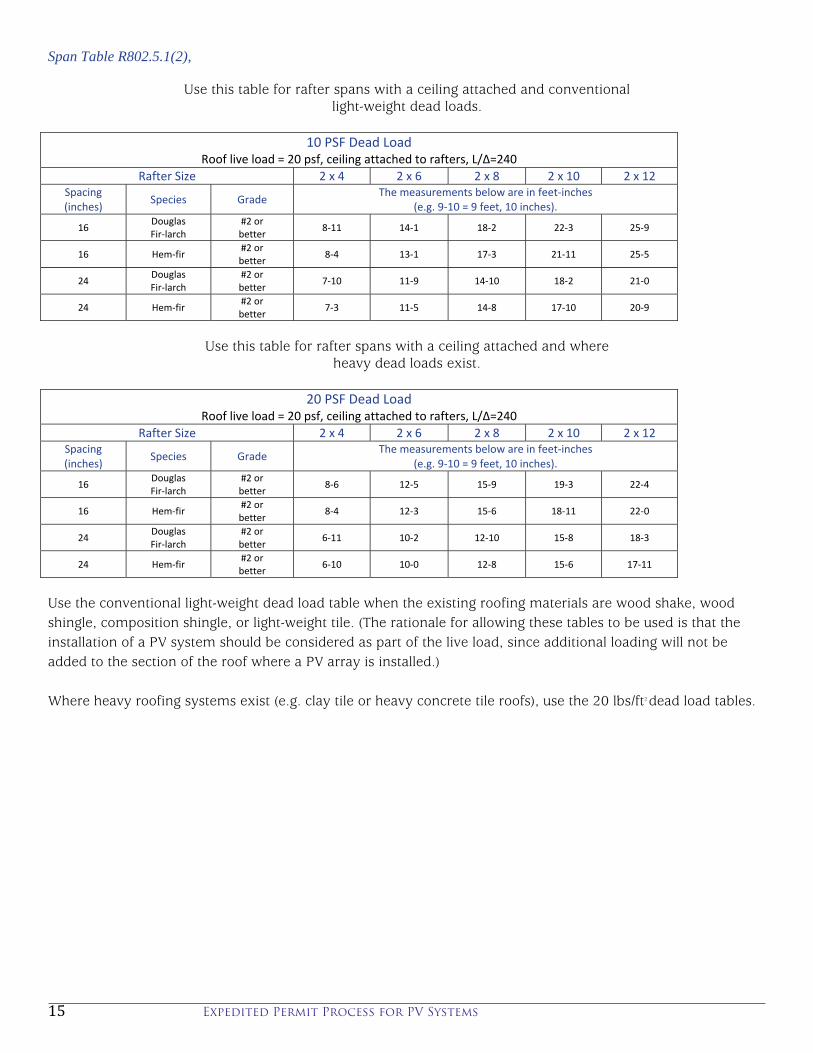
Span Table R802.5.1(2),
Use this table for rafter spans with a ceiling attached and conventional light-weight dead loads.
10 PSF Dead Load
Roof live load = 20 psf, ceiling attached to rafters, L/Δ=240
Rafter Size 2 x 4 2 x 6 2 x 8 2 x 10 2 x 12Spacing (inches) Species Grade
The measurements below are in feet‐inches (e.g. 9‐10 = 9 feet, 10 inches).
16 Douglas Fir‐larch
#2 or better 8‐11 14‐1 18‐2 22‐3 25‐9
16 Hem‐fir #2 or better 8‐4 13‐1 17‐3 21‐11 25‐5
24 Douglas Fir‐larch
#2 or better 7‐10 11‐9 14‐10 18‐2 21‐0
24 Hem‐fir #2 or better 7‐3 11‐5 14‐8 17‐10 20‐9
Use this table for rafter spans with a ceiling attached and where
heavy dead loads exist.
20 PSF Dead Load Roof live load = 20 psf, ceiling attached to rafters, L/Δ=240
Rafter Size 2 x 4 2 x 6 2 x 8 2 x 10 2 x 12Spacing (inches)
Species Grade The measurements below are in feet‐inches
(e.g. 9‐10 = 9 feet, 10 inches).
16 Douglas Fir‐larch
#2 or better 8‐6 12‐5 15‐9 19‐3 22‐4
16 Hem‐fir #2 or better 8‐4 12‐3 15‐6 18‐11 22‐0
24 Douglas Fir‐larch
#2 or better 6‐11 10‐2 12‐10 15‐8 18‐3
24 Hem‐fir #2 or better 6‐10 10‐0 12‐8 15‐6 17‐11
Use the conventional light-weight dead load table when the existing roofing materials are wood shake, wood shingle, composition shingle, or light-weight tile. (The rationale for allowing these tables to be used is that the installation of a PV system should be considered as part of the live load, since additional loading will not be added to the section of the roof where a PV array is installed.) Where heavy roofing systems exist (e.g. clay tile or heavy concrete tile roofs), use the 20 lbs/ft2 dead load tables.