CI/SfB January 2006 Mineral Fibre Full Fill Batt Cavity ... · Insulation Mineral Fibre Full Fill...
28
Insulation Mineral Fibre Full Fill Batt Cavity Wall Insulation, Workmanship, Water & Heat Loss A WHITE PAPER CI/SfB (47) Nh2 January 2006
Transcript of CI/SfB January 2006 Mineral Fibre Full Fill Batt Cavity ... · Insulation Mineral Fibre Full Fill...
I nsu la t ion
Mineral Fibre Full Fill Batt Cavity Wall Insulation, Workmanship, Water & Heat LossA WHITE PAPER
CI/SfB(47) Nh2
January 2006
Executive Summary 3
Introduction 4
Thermal Insulation and Water 5
Rain Penetration and Cavity Walls 6
Condensation and Cavity Walls 9
Workmanship and Cavity Walls 10
Case Studies – Workmanship 11
Case Studies – Summary of Results 16
Consequences 17
Case Study – Consequences 20
Remedies 21
Kingspan Insulation Solutions 22
Appendix A – Energy, CO2 and
Financial Calculations 25
Contents
2
3
1 Executive Summary
1.1 Kingspan Insulation Ltd has carried out a photographicsurvey of a number of sites using mineral fibre full fill battcavity wall insulation in London, Surrey, Oxfordshire,Humberside and Cheshire.
1.2 This survey uncovered endemic site practices which canbe seen to be contrary to the requirements orrecommendations laid down in many mineral fibre full fillbatt cavity wall insulation manufacturers’ literature,manufacturers’ BBA Certificates, BS 6676: Part 2: 1986(Code of practice for installation of batts (slabs) filling thecavity) or NHBC Standards (Vol. 2: Chapter 6.1).
1.3 These site practices can lead to construction defectswhich encourage water, from whatever source, topenetrate into the mineral fibre full fill batt cavity wall insulation.
1.4 This ‘White Paper’ goes on to show that it would bereasonable to expect that, in the UK, the averagemoisture content of installed mineral fibre full fill battcavity wall insulation would be 1% water by volume for75% of the year and that a moisture content of only 1% by volume can increase the thermal conductivity ofman made mineral fibre by between 75 and 105%.
1.5 This thermal conductivity increase would cause anadditional 1176 kWh of heat to be lost from a property of115 m2 wall area in one year. This additional heat loss isresponsible for 337 kg of CO2 equivalent emissions peryear and a financial loss of £26 per year.
1.6 The effects of this increased heat loss are graphicallydemonstrated in a thermographic survey on two houses,one insulated with mineral fibre full fill batt and the otherwith Kingspan partial fill slab.
1.7 Assuming this increase in thermal conductivity isrepresentative of all buildings insulated in this way, theuse of mineral fibre full fill batt cavity wall insulation couldbe regarded as wasting the UK 1764 GWh (million kWh)of heat per year.
1.8 That is equivalent to the output of 0.588 power stationsat an average output of 3000 GWh.
1.9 Furthermore, this could be regarded as causing 505.5million kg (505,500 T) of CO2 equivalent emission to bepumped into the atmosphere per year with itsconsequent effects on global warming.
1.10 That is equivalent to 0.61% of the UK’s commitment toCO2 equivalent emissions reduction under the 1997Kyoto Protocol of 83 million T of CO2 equivalentemissions (12.5% reduction from 1990 emission levels).
1.11 Finally, this could be regarded as costing occupiers of properties so insulated £39 million per year in wastedfuel bills.
1.12 Little can be done to remedy the effects that inadequatesite workmanship and supervision have on wallsinsulated with mineral fibre full fill batt cavity wallinsulation.
1.13 The only solution is to make the external leaf asimpermeable to water as possible with renders, siliconetreatments or other such remedies. All are expensive.
4
2 Introduction
2.1 This ‘White Paper’ from Kingspan Insulation is one of aseries, highlighting the serious implications thatinadequate site workmanship and supervision can haveon the performance of insulation materials.
2.2 Most insulation materials perform as claimed undercontrolled installation conditions and when tested in alaboratory environment. However, when taken into theworld of real site practices, not all may perform aspredicted.
2.3 This ‘White Paper’ focuses on the implications thatinadequate site workmanship and supervision can haveon the performance of mineral fibre full fill batt cavity wallinsulation. In particular it investigates the effects ofinappropriate installation techniques and theirconsequences for exacerbated heat loss and theenvironmental and financial implications of this.
2.4 For the purposes of this ‘White Paper’ the definition ofmineral fibre is taken from BS 3533: 1981 (Glossary ofthermal insulation terms) and includes both glass fibreand rock fibre.

5
3 Thermal Insulation and Water
3.1 The thermal insulating property of a material is expressedas its thermal conductivity. The lower the thermalconductivity the greater the material’s ability to resist heatflow and therefore the better it will act as an insulant. Thethermal conductivities for commonly used insulantstypically lie in the range of 0.021 to 0.046 W/m.K. Thesevalues relate to the insulation product at a specifictemperature in a dry and stable state.
3.2 The thermal conductivity of water (0.58 W/m.K) issignificantly higher than the thermal conductivity of anycommonly used insulant. Therefore if water is present theoverall thermal conductivity of the material will increasesignificantly. The level of increase will be dependant onthe volume of water present.
3.3 Water absorption by an insulant can be expressed as apercentage by volume or a percentage by weight. Apercentage by volume is the normal expression and asthe insulant itself has a certain solid volume thepercentage of water is always less than 100%. If watercontent is expressed as a percentage weight, this can begreater than 100% as insulants generally tend to besignificantly lighter than water. A 1% water content byvolume could result in up to a 50% content by weightdue to the lightness in weight of some insulants.
3.4 High performance closed cell insulants such as thosesupplied by Kingspan Insulation achieve much of theirinsulating qualities from the blowing agents which aretrapped within the cells of the material. Water is notreadily absorbed as it must penetrate through the cellwalls to enter the material. This does not readily occurunless the cell walls have been damaged, e.g. at cutedges. Where it does occur under normal applicationconditions, the amount of water absorption is very lowand is restricted to the outer cells, therefore having aminimal effect on the overall thermal conductivity of thematerial. Absorption is effectively eliminated if the insulantis faced with an impervious facing such as foil.
3.5 Mineral fibre insulants rely largely on entrapped air formuch of their insulating properties. Their open structuremay provide little resistance to water or vapour flow andthe potential for water and water vapour penetration cantherefore be high.
6
4 Rain Penetration and Cavity Walls
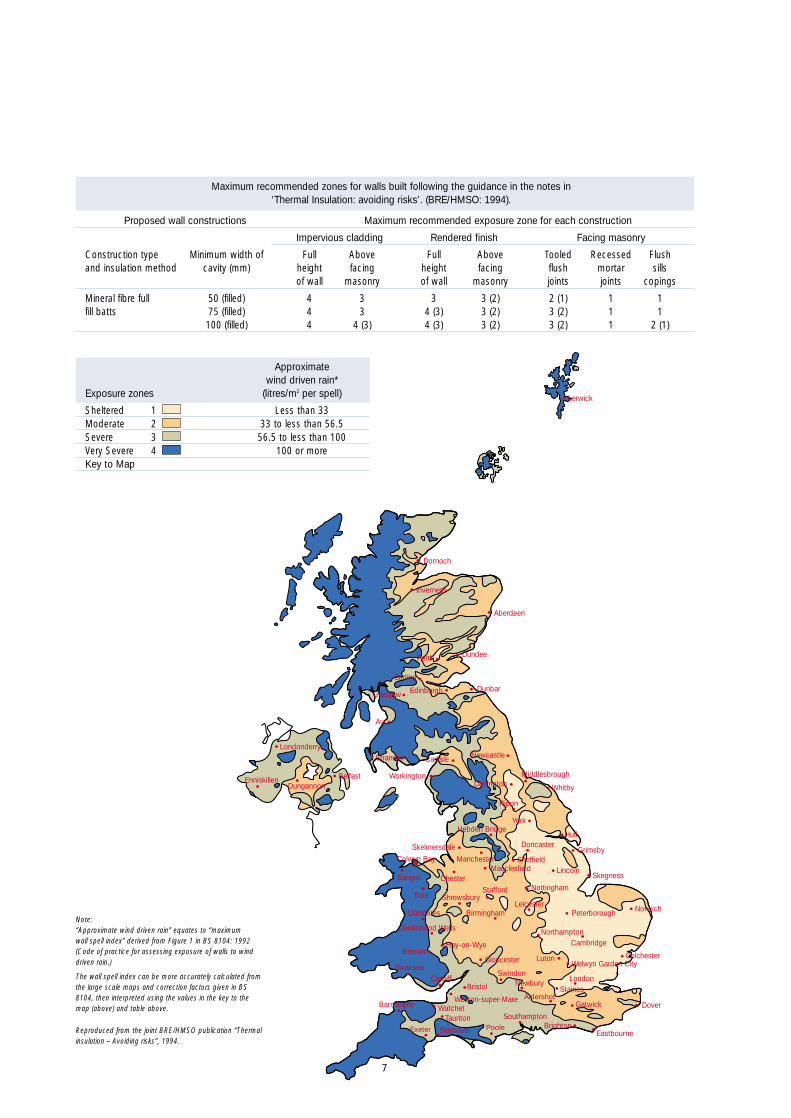
4.5 ‘Thermal insulation: avoiding risks’ (BRE/HMSO. 1994)gives a height limitation of 12 m for the use of mineralfibre full fill batt cavity wall insulation and gives thefollowing guidance.
● Determine the national exposure zone from the mapopposite and apply it to the table. Where necessarymodify zone to allow for the factors given below, orlocal knowledge and practice.
● Add one to the map zone where conditionsaccentuate wind effects such as on open hillsides orin valleys where the wind is tunnelled onto the wall.
● Subtract one from the map zone where walls are wellprotected by trees or buildings or do not face theprevailing wind.
● Consider restricting use to zones in bracketsif design or construction standard cannot be relied on.
If in doubt, these factors are fully described in BS 8104,with worked examples.
4.1 Cavity walls are designed such that the outer face isallowed to ‘fail’ and act solely as a first means of defenceagainst rain penetration.
4.2 The whole purpose of the ‘cavity’ is to act as a zonewhere penetrating water can freely drain to controlled exitpoints without crossing to the interior. By introducing fullfill insulation the basic function of the cavity wallconstruction can be compromised.
4.3 ‘Rainwater will penetrate the outer leaves of masonrywalls under certain conditions of driving rain. This canlead to dampness reaching the inside causing damage tothe wall and decorations and reducing thermalperformance’. ‘The performance of the wall in resistingwater crossing the cavity is affected by the amount ofwind driven rain, the presence of a finish or claddingwhich protects the wall and the quality of the design,specifications and workmanship’. ‘Moisture transmissionto the inner leaf of cavity walls is more likely where wallscontain building defects and cavity insulation’. (ThermalInsulation: avoiding risks. BRE/HMSO. 1994)
4.4 Mineral fibre manufacturers’ BBA Certificates for full fillbatt cavity wall insulation permit the products’ usesubject to a height limitation of 25 m and an exposurelimitation for buildings over 12 m in height. However, theystate that it is essential that the walls are built inaccordance with the conditions set out in the DesignData and Installation sections of the Certificates.Stringent design and workmanship requirements aremade in these sections. Buildings over 12 m in height are also required to have site supervision from themanufacturer.
7
Maximum recommended zones for walls built following the guidance in the notes in‘Thermal Insulation: avoiding risks’. (BRE/HMSO: 1994).
Proposed wall constructions Maximum recommended exposure zone for each construction
Impervious cladding Rendered finish Facing masonry
Construction type Minimum width of Full Above Full Above Tooled Recessed Flushand insulation method cavity (mm) height facing height facing flush mortar sills
of wall masonry of wall masonry joints joints copings
Mineral fibre full 50 (filled) 4 3 3 3 (2) 2 (1) 1 1fill batts 75 (filled) 4 3 4 (3) 3 (2) 3 (2) 1 1
100 (filled) 4 4 (3) 4 (3) 3 (2) 3 (2) 1 2 (1)
Note:“Approximate wind driven rain” equates to “maximum wall spell index” derived from Figure 1 in BS 8104: 1992(Code of practice for assessing exposure of walls to winddriven rain.)
The wall spell index can be more accurately calculated fromthe large scale maps and correction factors given in BS8104, then interpreted using the values in the key to themap (above) and table above.
Reproduced from the joint BRE/HMSO publication “Thermalinsulation – Avoiding risks”, 1994.
Approximatewind driven rain*
Exposure zones (litres/m2 per spell)
Sheltered 1 Less than 33Moderate 2 33 to less than 56.5Severe 3 56.5 to less than 100Very Severe 4 100 or moreKey to Map
Inverness
Dornoch
Aberdeen
DundeePerth
Stirling
Edinburgh DunbarGlasgow
Ayr
StranraerLondonderry
EnniskillenDungannon
Belfast
Carlisle Newcastle
MiddlesbroughDarlington Whitby
Ripon
York
HullDoncaster
Grimsby
LincolnSkegness
NorwichPeterboroughLeicester
Nottingham
Hebden Bridge
SheffieldMacclesfield
Chester
Colwyn Bay
Bangor
Bala Shrewsbury
Birmingham
Stafford
Llanidloes
Llandrindod Wells
Brecon
SwanseaCardiff
Bristol
Weston-super-MareWatchet
Taunton
Barnstaple
Exeter Sidmouth Poole
SouthamptonBrighton
Eastbourne
DoverGatwickAldershot
StainesLondon
Welwyn Garden CityColchesterLuton
CambridgeNorthampton
NewburySwindon
Hay-on-Wye
Gloucester
Manchester
Skelmersdale
Workington
Lerwick
8
4 Rain Penetration and Cavity Walls
4.6 Recognising the consequent need for exposurelimitations on mineral fibre full fill batts the NHBC statethat under their standards “In Scotland, it is notpermissible to fill the full width of the cavity with anythermal insulant at the time of construction”. (NHBCStandards. Volume 2, Chapter 6.1. 1992.)
4.7 They go on to say that for any part of the UK, a very highstandard of workmanship is required to ensure thatcavities are not bridged and to minimise the risk of damppenetration to the inside of the dwelling where cavityinsulation is used. (NHBC Standards. Volume 2, Chapter6.1. 1992.)
4.8 Indeed, following record claims for damage caused byrain penetration during the storms of 1989-1991, theNHBC have demanded that builders “Do not use (full fill)cavity wall insulation unless your standards are very high”(NHBC Standards Extra. Issue 1. September 1991.), andhave stated that “The problems stem from poor quality ofworkmanship in the cavities.” (Ian Davis, NHBC Directorof Standards. Building Magazine. Sept 27, 1991.)
4.9 Even Eurisol, the mineral fibre manufacturers tradeassociation, recognises that walls insulated with full fillbatts can suffer rain penetration because of badworkmanship, and that in this case dirty cavities are oneof the main causes.
9
5 Condensation and Cavity Walls
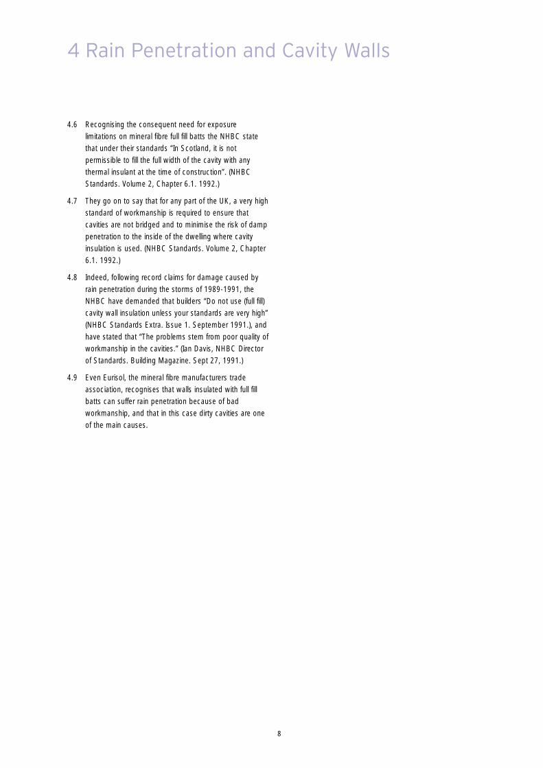
5.1 Rain penetration is not the only source of water in acavity wall. Walls built with mineral fibre full fill batt cavitywall insulation can suffer from the formation of interstitialcondensation.
5.2 Interstitial condensation calculations are performed toBS5250: 2002 (Code of practice for control ofcondensation in buildings). An example calculation for abrick / block wall insulated with mineral fibre full fill battcavity wall insulation is shown below.
5.3 The amount of condensate predicted to accumulate overa 60 day winter period is 427 g/m2 wall area.
5.4 This condensation will be worse at the time of year whenthe insulating performance of the mineral fibre full fill battcavity wall insulation is most required, when externaltemperatures are coldest.
25°C
20°C
15°C
10°C
5°C
0°C
–5°COutsideInside
T
D
Values at Interfaces
Element Description Element Thermal Thermal Vapour Vapour Vapour Structure Dewpoint CondensationThickness Conductivity Resistance Resistivity Resistance Pressure Temperature Temperature Risk
(mm) (W/m.k) (m2K/W) (MNs/gm) (MNs/g) (kPa) (°C) (°C) (kg/60 days)
Outside surface resistance – – 0.040 – – 0.549 0.3 –1.3Brickwork facing 102.5 0.770 0.133 42.00 4.31 0.669 1.3 1.3 0.414Mineral fibre full fill batt 75.0 0.037 2.027 10.00 0.75 0.750 16.1 2.9Blockwork 600 Kg 100.0 0.400 0.250 45.00 4.50 1.234 71.9 10.1AIR 10mm U/V; HOR FLOW; HI EM. 10.0 – 0.110 – 0.00 1.234 18.7 10.1Plasterboard 9.5 0.190 0.050 50.00 0.47 1.234 19.1 10.7Inside surface resistance – – 0.130 – –
Internal conditions: 20.0°C @ 55.0%RHExternal conditions: 0.0°C @ 90.0%RH
Calculated U-value = 0.37 W/m2.K (Based on the proportional area calculation method for determining U-values of structurescontaining repeating thermal bridges.)
Condensation calculations performed in accordance with BS 5250: 2002Calculated ‘Q’ value under notional winter conditions over 60 days = 0.414 kg/m2
6 Workmanship and Cavity Walls
6.1 Installation of mineral fibre full fill batt cavity wall insulationin accordance with BS 6676: Part 2: 1986 (Code ofpractice for installation of batts (slabs) filling the cavity.)requires that the outer leaf of the cavity wall be built asthe leading leaf so that mortar snots can be cleaned offits inner surface. The same is recommended bymanufacturers’ BBA Certificates.
6.2 This is contrary to the practice adopted at many sites inthe UK where work is usually undertaken from theoutside face of the wall, as constructing the outer leaf asthe leading skin would require work to be undertakenfrom within the building, reducing accessibility forfollowing trades.
6.3 Many mineral fibre full fill batt cavity wall insulationmanufacturers’ literature endorses this constructionsequence contrary to the Code of Practice.
6.4 It is also recommended by many mineral fibre full fill battcavity wall insulation manufacturers that cavity battens /boards be used to keep mineral fibre full fill batt junctionsand wall ties free from mortar droppings.The same is required by manufacturers’ BBA Certificatesand BS 6676: Part 2: 1986 and is recommended byNHBC Standards (Volume 2, Chapter 6.1).
6.5 Cavity battens or boards are used.
6.6 The effect of the above can be to create dirty cavities,mortar snots on the inner faces of outer leaves andmortar droppings between mineral fibre full fill batts, allencouraging water, from whatever source, to penetrateinto the full fill batts.
6.7 Other site practices which can lead to water penetrationinclude:
● installation of small pieces of mineral fibre full fill battwith fibres in incorrect orientations;
● installation of mineral fibre full fill batts that are wet orweathered resulting from poor storage or protection;
● badly fitted mineral fibre full fill batts with fibres inincorrect orientations or folded;
● installation of torn or damaged mineral fibre full fill batts;
● missing mineral fibre full fill batts;
● gaps left between mineral fibre full fill batts; and
● construction of both skins above the top of themineral fibre full fill batts creating a trough and makingproper installation of full fill batts impossible (mineralfibre full fill batts will require forcing into the gap,cleaning of the mineral fibre full fill batts’ surfaces andensuring no gaps between mineral fibre full fill battswill be extremely difficult).
6.8 It is recommended by many mineral fibre full fill battcavity wall insulation manufacturers that sites are keptfree of these practices. The same is required bymanufacturers’ BBA Certificates, BS 6676: Part 2: 1986and NHBC Standards (Volume 2, Chapter 6.1).

11
7 Case Studies – Workmanship
7.1 Kingspan Insulation Ltd has carried out a photographicsurvey of a number of sites using mineral fibre full fill battcavity wall insulation. The sites surveyed were in London,Surrey, Oxfordshire, Humberside and Cheshire.
Image 1This image is of the London site. There is no evidence of a cavity board orbatten in use. This has led to the accumulation of mortar on the top surfaceof the mineral fibre full fill batts. The inner leaf of blockwork has been built upfirst which has prevented the striking of mortar from the joints on the cavityface of the brickwork, leaving mortar snots projecting into the cavity depth.Both leaves have been constructed above the top of the mineral fibre full fillbatts leaving a trough which makes the proper installation of full fill battsimpossible (mineral fibre full fill batts will require forcing into the gap, cleaningof the mineral fibre full fill batts’ surfaces and ensuring no gaps betweenmineral fibre full fill batts will be extremely difficult).
Image 2This image is of the London site. Comments as for Image 1, with the additionof dirty wall ties caused by the lack of use of a cavity board or batten.
12
7 Case Studies – Workmanship
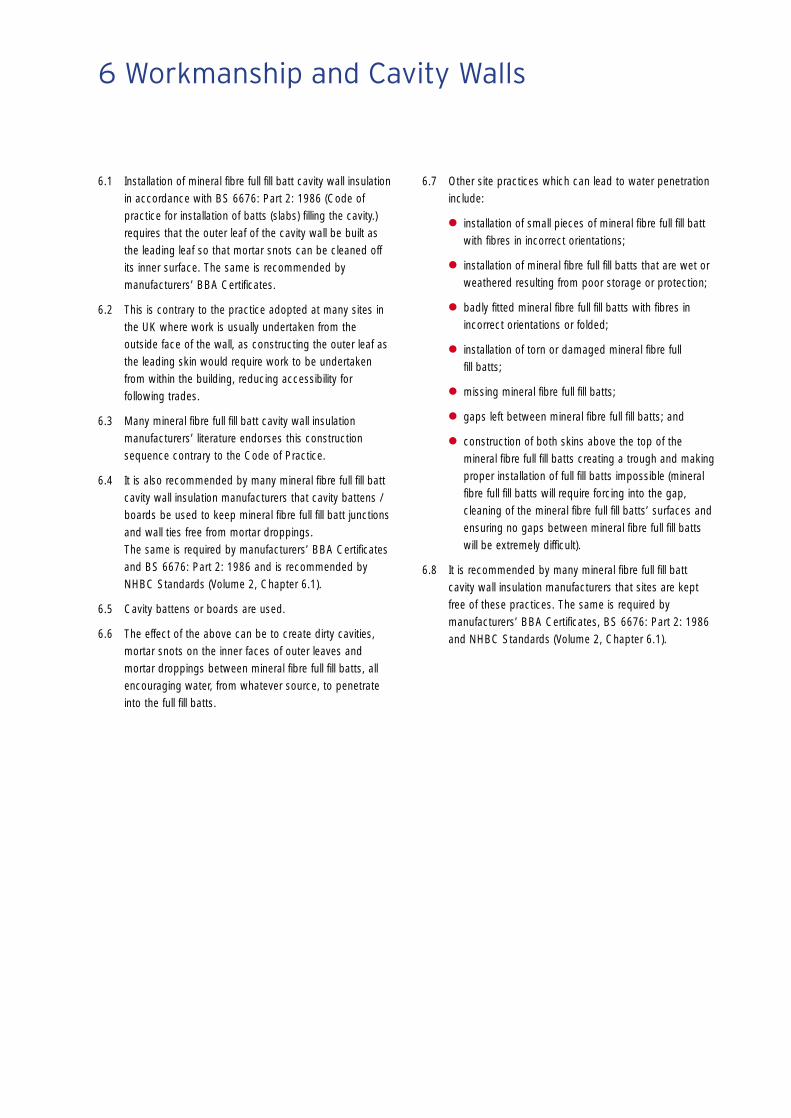
Image 3This image is of the London site. Comments as for Image 1. The wall tie inthe foreground of the picture makes remedial action even more difficult if notimpossible. There are large gaps between the mineral fibre full fill batts andover compression of mineral fibre full fill batts contrary to BS 6676: Part 2:1986.
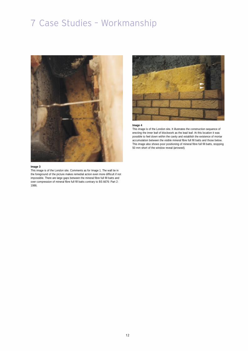
Image 4This image is of the London site. It illustrates the construction sequence oferecting the inner leaf of blockwork as the lead leaf. At this location it waspossible to feel down within the cavity and establish the existence of mortaraccumulation between the visible mineral fibre full fill batts and those below.This image also shows poor positioning of mineral fibre full fill batts, stopping50 mm short of the window reveal (arrowed).
13
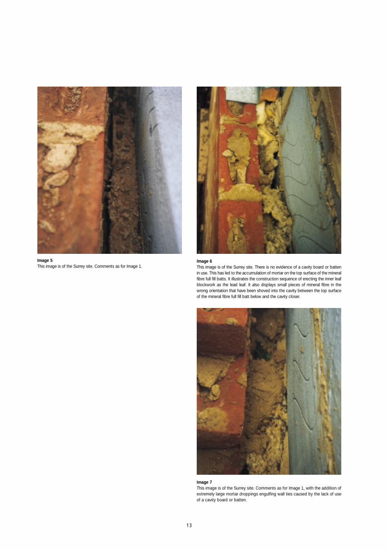
Image 5This image is of the Surrey site. Comments as for Image 1.
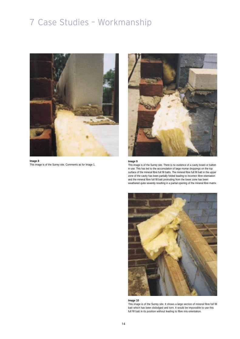
Image 6This image is of the Surrey site. There is no evidence of a cavity board or battenin use. This has led to the accumulation of mortar on the top surface of the mineralfibre full fill batts. It illustrates the construction sequence of erecting the inner leafblockwork as the lead leaf. It also displays small pieces of mineral fibre in thewrong orientation that have been shoved into the cavity between the top surfaceof the mineral fibre full fill batt below and the cavity closer.
Image 7This image is of the Surrey site. Comments as for Image 1, with the addition ofextremely large mortar droppings engulfing wall ties caused by the lack of useof a cavity board or batten.
14
7 Case Studies – Workmanship
Image 9This image is of the Surrey site. There is no evidence of a cavity board or battenin use. This has led to the accumulation of large mortar droppings on the topsurface of the mineral fibre full fill batts. The mineral fibre full fill batt in the upperzone of the cavity has been partially folded leading to incorrect fibre orientationand the mineral fibre full fill batt protruding from the lower zone has beenweathered quite severely resulting in a partial opening of the mineral fibre matrix.
Image 10This image is of the Surrey site. It shows a large section of mineral fibre full fillbatt which has been dislodged and torn. It would be impossible to use thisfull fill batt in its position without leading to fibre mis-orientation.
Image 8This image is of the Surrey site. Comments as for Image 1.
15
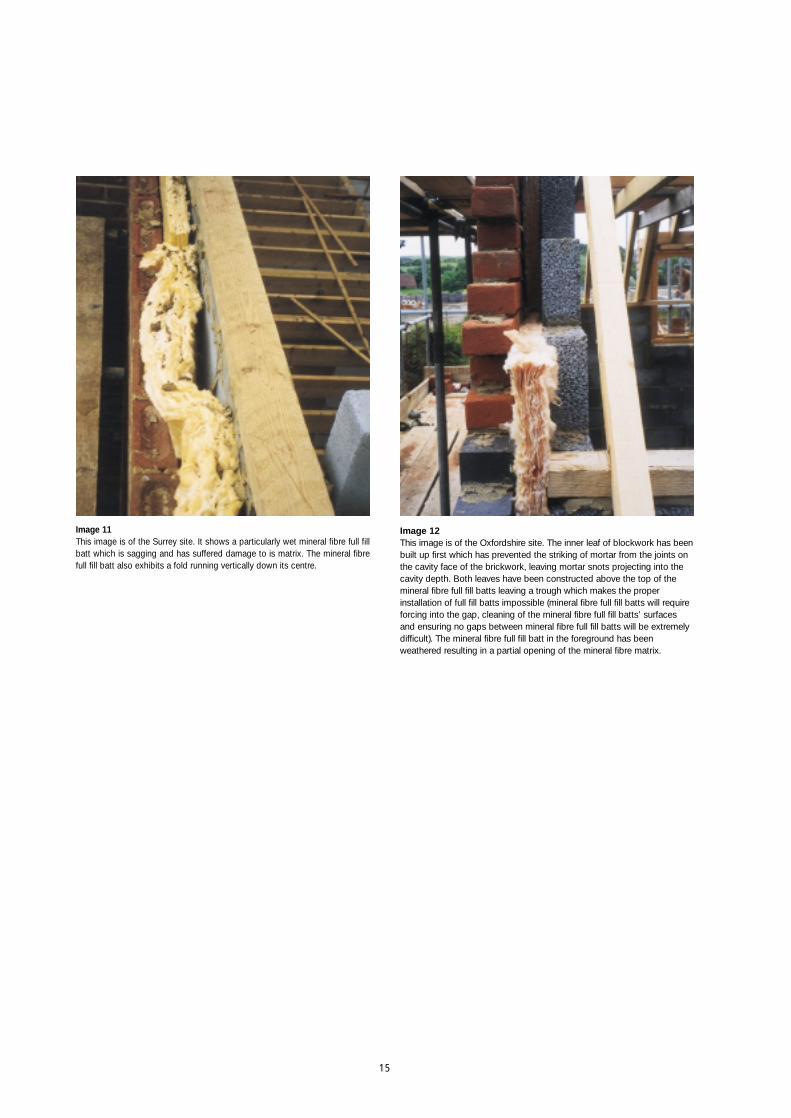
Image 11This image is of the Surrey site. It shows a particularly wet mineral fibre full fillbatt which is sagging and has suffered damage to is matrix. The mineral fibrefull fill batt also exhibits a fold running vertically down its centre.
Image 12This image is of the Oxfordshire site. The inner leaf of blockwork has beenbuilt up first which has prevented the striking of mortar from the joints onthe cavity face of the brickwork, leaving mortar snots projecting into thecavity depth. Both leaves have been constructed above the top of themineral fibre full fill batts leaving a trough which makes the properinstallation of full fill batts impossible (mineral fibre full fill batts will requireforcing into the gap, cleaning of the mineral fibre full fill batts’ surfacesand ensuring no gaps between mineral fibre full fill batts will be extremelydifficult). The mineral fibre full fill batt in the foreground has beenweathered resulting in a partial opening of the mineral fibre matrix.
16
7 Case Studies – Workmanship
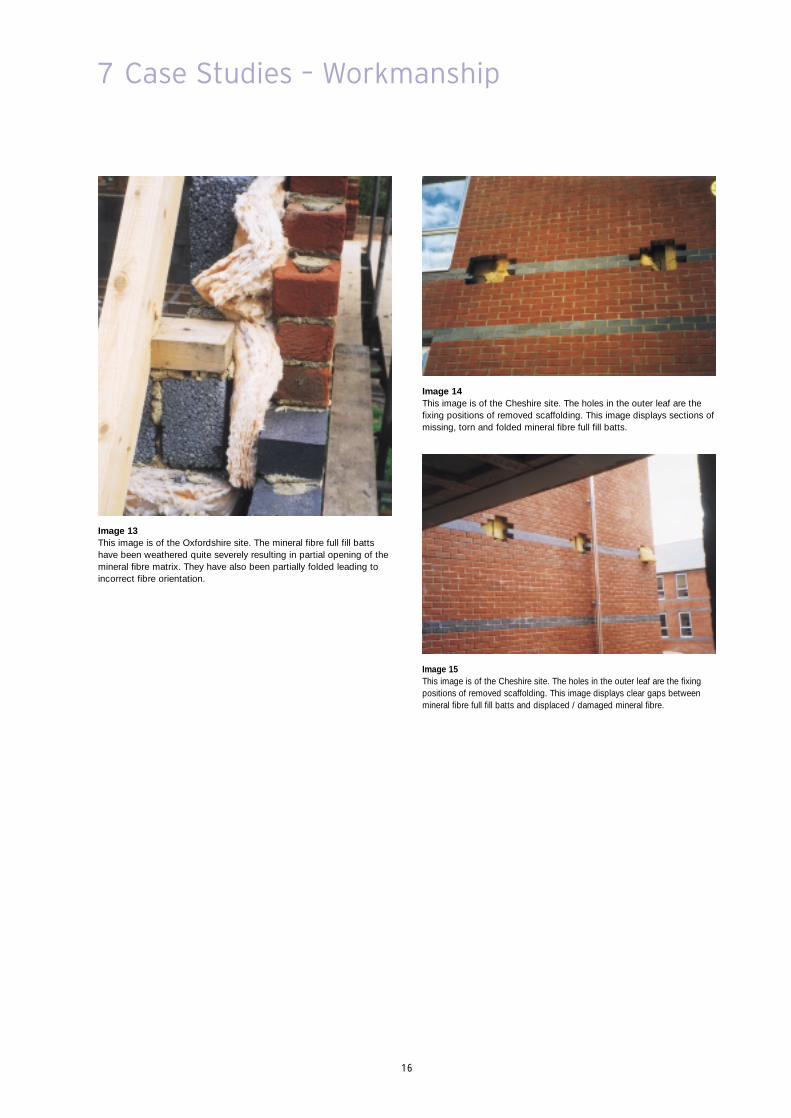
Image 14This image is of the Cheshire site. The holes in the outer leaf are thefixing positions of removed scaffolding. This image displays sections ofmissing, torn and folded mineral fibre full fill batts.
Image 15This image is of the Cheshire site. The holes in the outer leaf are the fixingpositions of removed scaffolding. This image displays clear gaps betweenmineral fibre full fill batts and displaced / damaged mineral fibre.
Image 13This image is of the Oxfordshire site. The mineral fibre full fill battshave been weathered quite severely resulting in partial opening of themineral fibre matrix. They have also been partially folded leading toincorrect fibre orientation.
17
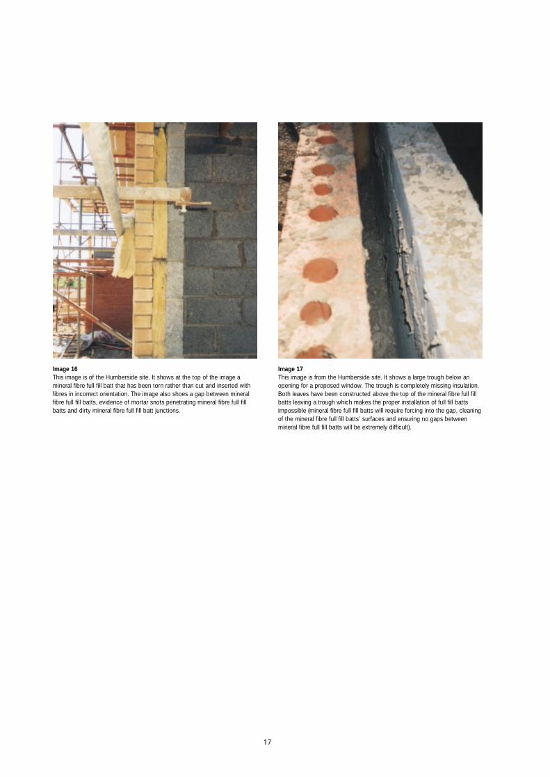
Image 16This image is of the Humberside site. It shows at the top of the image amineral fibre full fill batt that has been torn rather than cut and inserted withfibres in incorrect orientation. The image also shoes a gap between mineralfibre full fill batts, evidence of mortar snots penetrating mineral fibre full fillbatts and dirty mineral fibre full fill batt junctions.
Image 17This image is from the Humberside site. It shows a large trough below anopening for a proposed window. The trough is completely missing insulation.Both leaves have been constructed above the top of the mineral fibre full fillbatts leaving a trough which makes the proper installation of full fill battsimpossible (mineral fibre full fill batts will require forcing into the gap, cleaningof the mineral fibre full fill batts’ surfaces and ensuring no gaps betweenmineral fibre full fill batts will be extremely difficult).

18
8 Case Studies – Summary of Results
8.1 The procedure used in erecting the cavity walls at theLondon, Surrey and Oxfordshire sites involved buildingthe inner leaf blockwork as the lead leaf. See Images 4 &6. The Humberside and Cheshire sites were tooadvanced for the wall construction sequence to beascertained.
8.2 At the London, Surrey and Oxfordshire sites, no cavityboards or battens were being used to protect the topedge of the mineral fibre full fill batts or the wall ties frommortar droppings. See Images 1-13. The Humbersideand Cheshire sites were too advanced for the use ofcavity boards or battens to be assessed.
8.3 All sites displayed mortar remaining on top of the mineralfibre full fill batts and the London and Surrey sites hadwall cavities where mortar had covered a number of wallties. At the London, Surrey and Humberside sites it wasfound by manual or visual inspection that this debris wasnot removed prior to installation of subsequent mineralfibre full fill batts, and that the top surfaces of full fill battswere significantly dirtier below window positions thanelsewhere. See Images 1, 2, 4-8 and 16.
8.4 Installation of small pieces of mineral fibre full fill batt withfibres in incorrect orientations were seen on the Surreysite. See Image 6.
8.5 Wet or weathered mineral fibre full fill batts were seen onthe London, Surrey and Oxfordshire sites. See Images 9and 11-13.
8.6 Badly fitted mineral fibre full fill batts with fibres inincorrect orientations or folded were seen on all but theLondon site. See Images 9, 11, 13, 14 and 16.
8.7 Torn or damaged mineral fibre full fill batts were seen atthe Surrey, Cheshire and Humberside sites. See Images10, 14 and 16.
8.8 The construction of both leaves above the top of mineralfibre full fill batts leaving a trough was seen on all siteswith the exception of Cheshire. See Images 1-3, 5, 7, 8,12 and 17.
8.9 Both gaps left between mineral fibre full fill batts andmissing mineral fibre full fill batts were seen at theLondon, Cheshire and Humberside sites. See Images 4and 14-16.
8.10 These practices can all be seen to be contrary to therequirements or recommendations laid down in manymineral fibre full fill batt cavity wall insulationmanufacturers’ literature, manufacturers’ BBACertificates, BS 6676: Part 2: 1986 (Code of practice forinstallation of batts (slabs) filling the cavity) or NHBCStandards (Vol. 2: Chapter 6.1).

19
9 Consequences
9.1 A study by Sandberg has stated that wet mineral fibre fullfill batt cavity wall insulation will dry out in two stages.During the first stage, which will last for a couple if hours,gravity action will cause drainage of the material to awater content of 3-5% by volume except in the lower 10-20 cm, where the material remains saturated. Duringthe second stage which will last from a couple of days toa couple of months, the drying mechanism isvapourisation of water and diffusion of water vapour outof the material. He states that a water content of 3.8%by volume drying in 25 days would be consistent withthe effects of heavy rain and a water content of 0.5% byvolume drying in 4 days would be consistent with theeffects of light rain. (Sandberg, P.I. Thermal Resistance ofa Wet Mineral Fibre Insulation. Thermal Insulation:Materials and Systems. ASTM STP 922, pp 394-404.Powel, F.J. and Matthews, S.L., Eds. ASTM,Philadelphia, 1987.)
9.2 While dry mineral fibre insulants are air permeable, whenwet this characteristic is partially reduced which explainswhy drying out can take some considerable time. Themineral fibre relies on air movement to evaporate waterand remove it. In full fill situations this effect is limited andthus mineral fibre can remain with increased moisturecontent for longer periods. Since there is a relativelyimpervious layer (e.g. a brick wall) on the cold side of theinsulation the water vapour may condense on it.
9.3 Sandberg goes on to state that during the drying ofmoisture in the second stage, heat flows andtemperatures in the material are affected by phasechanges (i.e. additional heat is taken up from the warmside of the wall to vapourise the water and this heat isliberated on the cold side if and when the water vapourcondenses on the inner side of the brick outer leaf).These must also be considered when thermalconductivity design values are assessed.
9.4 Estimating UK weather patterns is a black art, but if weassume that from September to May there was a lightrain event every four days with no rain from June toAugust, installed mineral fibre full fill batt cavity wallinsulation would have an average background moisturecontent of 0.25% water by volume for 75% of the year(275 days). If five of these light rain events were heavyrain events, the average moisture content of the installedmineral fibre full fill batt cavity wall insulation would be1% water by volume for 75% of the year (150 days at anaverage of 0.25% by volume and 125 days at an averageof 1.9% by volume).
9.5 A study by Weiland has highlighted the fact that amoisture content of only 1% by volume can increase the thermal conductivity of man made mineral fibre by up to 75%. (Weiland H. Building Physics in a Roofwith Two Trapezoidal Sheets. Weiland Engineering AG,Maienfeld. 1993.)
9.6 A further study by Achtziger and Cammerer for theGerman Urbanism and Building Ministry has concludedthat 1% of moisture by volume in mineral fibre can leadto an increase in thermal conductivity of up to 105%.(Achtziger J. & Cammerer J. Einfluss desFeuchtegehaltes auf die Wärmeleitfähigkeit von Bau -Und Dämmstoffen. Bauforshungsberichte desBundesministers für Raumordnung, Bauwesen undStädtebau. 1988.)
20
9 Consequences
9.7 Taking an average of Weiland’s and Achtziger andCammerer’s results yields a 90% increase in thermalconductivity from 0.036 W/m.K to 0.068 W/m.K for atypical 75 mm mineral fibre full fill batt. In the brick /block wall detailed in Section 5 of this ‘White Paper’ thisincrease in thermal conductivity would increase the wallU-value from 0.36 W/m2.K to 0.55 W/m2.K.
9.8 Assuming that this increase in thermal conductivityoccurs over 75% of a year and over 75% of a buildingsurface area (56.25% of area and time combined), andusing the methodology detailed in the KingspanInsulation document ‘Lifetime Energy, CO2 and FinancialBalances for Insulation Materials - A White Paper’, thisthermal conductivity increase would cause an additional1176 kWh of heat to be lost from a property of 115 m2
wall area in one year. This is a 30% increase in heat lossfor the wall as a whole. This additional heat loss wouldbe responsible for 337 kg of CO2 equivalent emissionsper year and a financial loss of £26 per year.
9.9 Extrapolating data published by Eurisol (Cavity wallinsulation. Eurisol. October 1990.) 1.5 million propertiesin the UK have been insulated with mineral fibre full fillbatt cavity wall insulation. (Assumed 75,000 propertiesinsulated with full fill batt cavity wall insulation per yearpost 1988/89.)
9.10 Assuming this increase in thermal conductivity isrepresentative of all buildings insulated in this way, theuse of mineral fibre full fill batt cavity wall insulation couldbe regarded as wasting the UK 1764 GWh (million kWh)of heat per year.
9.11 That is equivalent to the output of 0.588 power stationsof an average output of 3000 GWh.
9.12 Furthermore, this could be regarded as causing 505.5 million kg (505,500 T) of CO2 equivalent emissionsto be pumped into the atmosphere per year with itsconsequent effects on global warming.
9.13 That is equivalent to 0.61 % of the UK’s commitment toCO2 equivalent emissions reduction under the 1997Kyoto Protocol of 83 million T of CO2 equivalentemissions (12.5% reduction from 1990 emission levels).
9.14 Finally, this could be regarded as costing occupiers ofproperties so insulated £39 million per year in wasted fuel bills.
9.15 These figures would be even worse if the effects ofdynamic heat transfer from phase changes andadditional water content from condensation were takeninto account.
9.16 It could be argued that if the thermal conductivity of the mineral fibre full fill batt cavity wall insulation were tobe debased, the risk of condensation would disappear,but this is not the case. It is simply lessened. Acalculation using an identical construction and conditionsto that used in Section 5, but with a λ-value of 0.068W/m.K for the mineral fibre full fill batt cavity wallinsulation is shown opposite.

21
9.17 The amount of condensate predicted to accumulate overa 60 day winter period is 347 g/m2 wall area.
25°C
20°C
15°C
10°C
5°C
0°C
–5°COutsideInside
T
D
Values at Interfaces
Element Description Element Thermal Thermal Vapour Vapour Vapour Structure Dewpoint CondensationThickness Conductivity Resistance Resistivity Resistance Pressure Temperature Temperature Risk
(mm) (W/m.K) (m2K/W) (MNs/gm) (MNs/g) (kPa) (°C) (°C) (kg/60 days)
Outside surface resistance – – 0.040 – – 0.549 0.4 –1.3Brickwork Facing 102.5 0.770 0.133 42.00 4.31 0.701 1.9 1.9 0.347Mineral fibre full fill batt 75.0 0.068 1.103 10.00 0.75 0.777 14.1 3.4Blockwork 600 Kg 100.0 0.400 0.250 45.00 4.50 1.230 16.8 10.1AIR 10mm U/V; HOR FLOW; HI EM. 10.0 – 0.110 – 0.00 1.236 18.0 10.1Plasterboard 9.5 0.190 0.050 50.00 0.47 1.285 18.6 10.7Inside surface resistance – – 0.130 – –
Internal conditions: 20.0°C @ 55.0%RHExternal conditions: 0.0°C @ 90.0%RH
Calculated U-value = 0.55 W/m2.K (Based on the proportional area calculation method for determining U-values of structurescontaining repeating thermal bridges.)
Condensation calculations performed in accordance with BS 5250: 2002Calculated ‘Q’ value under notional winter conditions over 60 days = 0.347 kg/m2
22
10 Case Study – Consequences
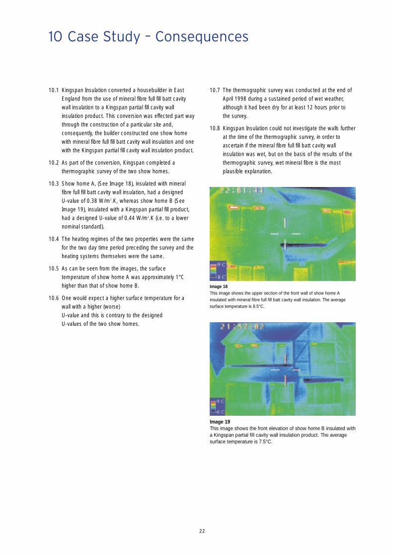
10.1 Kingspan Insulation converted a housebuilder in EastEngland from the use of mineral fibre full fill batt cavitywall insulation to a Kingspan partial fill cavity wallinsulation product. This conversion was effected part waythrough the construction of a particular site and,consequently, the builder constructed one show homewith mineral fibre full fill batt cavity wall insulation and onewith the Kingspan partial fill cavity wall insulation product.
10.2 As part of the conversion, Kingspan completed athermographic survey of the two show homes.
10.3 Show home A, (See Image 18), insulated with mineralfibre full fill batt cavity wall insulation, had a designed U-value of 0.38 W/m2.K, whereas show home B (SeeImage 19), insulated with a Kingspan partial fill product,had a designed U-value of 0.44 W/m2.K (i.e. to a lowernominal standard).
10.4 The heating regimes of the two properties were the samefor the two day time period preceding the survey and theheating systems themselves were the same.
10.5 As can be seen from the images, the surfacetemperature of show home A was approximately 1°Chigher than that of show home B.
10.6 One would expect a higher surface temperature for awall with a higher (worse)U-value and this is contrary to the designedU-values of the two show homes.
10.7 The thermographic survey was conducted at the end ofApril 1998 during a sustained period of wet weather,although it had been dry for at least 12 hours prior to the survey.
10.8 Kingspan Insulation could not investigate the walls furtherat the time of the thermographic survey, in order toascertain if the mineral fibre full fill batt cavity wallinsulation was wet, but on the basis of the results of thethermographic survey, wet mineral fibre is the mostplausible explanation.
Image 18This image shows the upper section of the front wall of show home Ainsulated with mineral fibre full fill batt cavity wall insulation. The averagesurface temperature is 8.5°C.
Image 19This image shows the front elevation of show home B insulated witha Kingspan partial fill cavity wall insulation product. The averagesurface temperature is 7.5°C.

23
11 Remedies
11.1 Little can be done to remedy the effects that inadequatesite workmanship and supervision have on walls insulatedwith mineral fibre full fill batt cavity wall insulation.
11.2 The only solution is to make the external leaf asimpermeable to water as possible with renders, siliconetreatments or other such remedies. All are expensive.

24
12 Kingspan Insulation Solutions
12.1 There are a number of solutions to the problemsidentified in this ‘White Paper’ that can be employedusing Kingspan Insulation products.
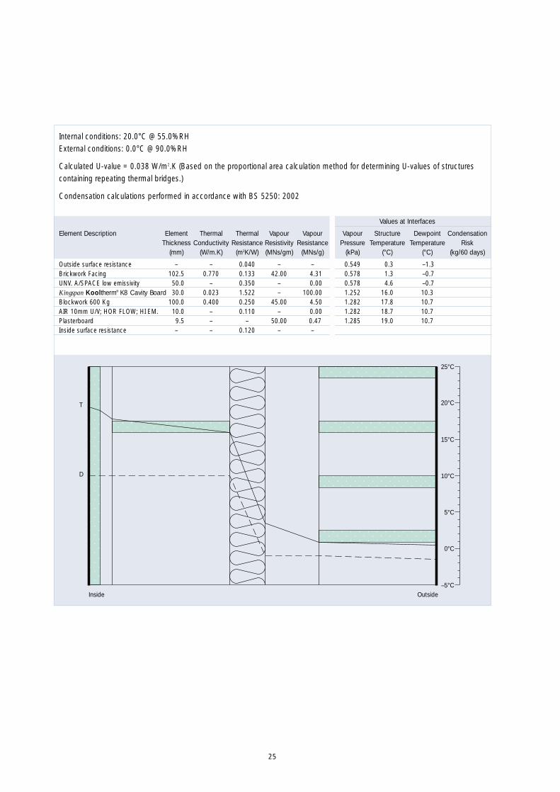
12.2 One of Kingspan Insulation’s products for partial fill cavitywall insulation can be used. The product is KingspanKooltherm® K8 Cavity Board. Thermographic images ofwalls so insulated are shown below.
12.3 This product design’s out the risk of condensationformation. Calculations using an identical constructionand conditions to that used in Sections 5 and 9, butusing Kingspan Kooltherm® K8 Cavity Board shown onthe next two pages. This product is chosen because it ischaracterised by having the lowest and highest λ-valuesof the three Kingspan Insulation products for partial fillcavity wall insulation. Both products have the samevapour resistance as they both have an integral foilfacing.
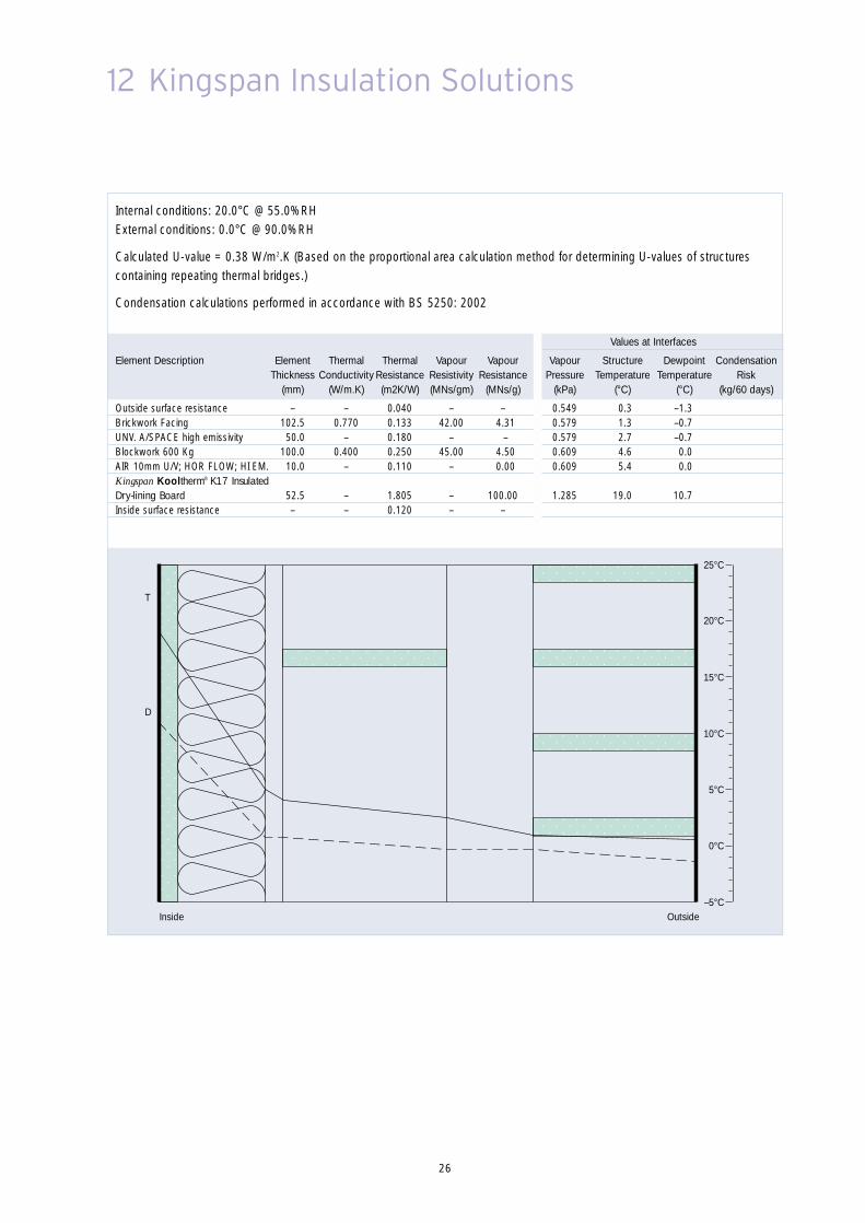
12.4 Kingspan Insulation’s product for insulated dry lining,Kingspan Kooltherm® K17 Insulated Dry-lining Boardcan also be used.
12.5 This product also designs out the risk of condensationformation. A calculation using an identical constructionand conditions to that used in Sections 5 and 9 above,but using Kingspan Kooltherm® K17 Insulated Dry-liningBoard is shown on page 26.
12.6 All of the Kingspan Insulation solutions detailed aboveretain an empty cavity within the structure of a cavitywall. Water has a negligible effect on the thermalperformance of Kingspan Insulation products. These twofactors combined mean that rain penetration is not anissue with Kingspan Insulation products.
Image 20The image shows a gable wall with a relatively even surface temperature. It isinsulated with Kingspan partial fill insulation. There are well insulated lintelswith no debris. Very little thermal bridging at this position can be identified.There is also very little air leakage at the verge. It should be noted that therooms behind are well heated which further displays the well insulated natureof the construction.
Image 21This image displays the uniform thermal patterns which are associated with awell performing wall insulation system. It is insulated with Kingspan partial fillinsulation. Some localised surface cooling is noticed due to wind effects.
25
25°C
20°C
15°C
10°C
5°C
0°C
–5°COutsideInside
T
D
Values at Interfaces
Element Description Element Thermal Thermal Vapour Vapour Vapour Structure Dewpoint CondensationThickness Conductivity Resistance Resistivity Resistance Pressure Temperature Temperature Risk
(mm) (W/m.K) (m2K/W) (MNs/gm) (MNs/g) (kPa) (°C) (°C) (kg/60 days)
Outside surface resistance – – 0.040 – – 0.549 0.3 –1.3Brickwork Facing 102.5 0.770 0.133 42.00 4.31 0.578 1.3 –0.7UNV. A/SPACE low emissivity 50.0 – 0.350 – 0.00 0.578 4.6 –0.7Kingspan Kooltherm® K8 Cavity Board 30.0 0.023 1.522 – 100.00 1.252 16.0 10.3Blockwork 600 Kg 100.0 0.400 0.250 45.00 4.50 1.282 17.8 10.7AIR 10mm U/V; HOR FLOW; HI EM. 10.0 – 0.110 – 0.00 1.282 18.7 10.7Plasterboard 9.5 – – 50.00 0.47 1.285 19.0 10.7Inside surface resistance – – 0.120 – –
Internal conditions: 20.0°C @ 55.0%RHExternal conditions: 0.0°C @ 90.0%RH
Calculated U-value = 0.038 W/m2.K (Based on the proportional area calculation method for determining U-values of structurescontaining repeating thermal bridges.)
Condensation calculations performed in accordance with BS 5250: 2002
26
12 Kingspan Insulation Solutions
Values at Interfaces
Element Description Element Thermal Thermal Vapour Vapour Vapour Structure Dewpoint CondensationThickness Conductivity Resistance Resistivity Resistance Pressure Temperature Temperature Risk
(mm) (W/m.K) (m2K/W) (MNs/gm) (MNs/g) (kPa) (°C) (°C) (kg/60 days)
Outside surface resistance – – 0.040 – – 0.549 0.3 –1.3Brickwork Facing 102.5 0.770 0.133 42.00 4.31 0.579 1.3 –0.7UNV. A/SPACE high emissivity 50.0 – 0.180 – – 0.579 2.7 –0.7Blockwork 600 Kg 100.0 0.400 0.250 45.00 4.50 0.609 4.6 0.0AIR 10mm U/V; HOR FLOW; HI EM. 10.0 – 0.110 – 0.00 0.609 5.4 0.0Kingspan Kooltherm® K17 InsulatedDry-lining Board 52.5 – 1.805 – 100.00 1.285 19.0 10.7Inside surface resistance – – 0.120 – –
Internal conditions: 20.0°C @ 55.0%RHExternal conditions: 0.0°C @ 90.0%RH
Calculated U-value = 0.38 W/m2.K (Based on the proportional area calculation method for determining U-values of structurescontaining repeating thermal bridges.)
Condensation calculations performed in accordance with BS 5250: 2002
25°C
20°C
15°C
10°C
5°C
0°C
–5°COutsideInside
T
D
27
Appendix A – Energy, CO2 and FinancialCalculations
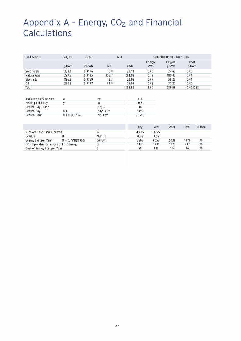
Fuel Source CO2 eq. Cost Mix Contribution to 1 kWh Total
Energy CO2 eq. Costg/kWh £/kWh MJ kWh kWh g/kWh £/kWh
Solid Fuels 389.1 0.0176 76.0 21.11 0.06 24.62 0.00Natural Gas 227.2 0.0185 953.7 264.92 0.79 180.43 0.01Electricity 896.9 0.0769 79.3 22.03 0.07 59.23 0.01Oil 290.3 0.0177 91.9 25.53 0.08 22.22 0.00Total 333.58 1.00 286.50 0.022238
Insulation Surface Area a m2 115Heating Efficiency yr % 0.8Degree-Days Base deg C 18Degree-Day DD days K/yr 3190Degree-Hour DH = DD * 24 hrs K/yr 76560
Dry Wet Aver. Diff. % Incr.
% of Area and Time Covered % 43.75 56.25U-value U W/m2.K 0.36 0.55Energy Lost per Year Q = (U*a*H)/1000r kWh/yr 3962 6053 5138 1176 30CO2 Equivalent Emissions of Lost Energy kg 1135 1734 1472 337 30Cost of Energy Lost per Year £ 88 135 114 26 30
www.insulation.kingspan.com
® Kingspan, Kooltherm and the Lion Device are Registered Trademarks of the Kingspan Group plc
Customer ServiceFor quotations, order placement and details of despatches pleasecontact the Kingspan Insulation Customer Services Department onthe numbers below:
UK – Telephone: +44 (0) 870 850 8555– Fax: +44 (0) 870 850 8666– email: [email protected]
Ireland – Telephone: +353 (0) 42 97 95000– Fax: +353 (0) 42 97 46129– email: [email protected]
Literature & SamplesKingspan Insulation produce a comprehensive range of technicalliterature for specifiers, contractors, stockists and end users. The literature contains clear ‘user friendly’ advice on typical design; design considerations; thermal properties; sitework and product data.
Available as a complete Design Manual or as individual productbrochures, Kingspan Insulation technical literature is an essentialspecification tool. For copies please contact the KingspanInsulation Marketing Department on the numbers below:
UK – Telephone: +44 (0) 870 733 8333– Fax: +44 (0) 1544 387 299– email: [email protected]
Ireland – Telephone: +353 (0) 42 97 95038– Fax: +353 (0) 42 97 46129– email: [email protected]
Tapered RoofingFor technical guidance, quotations, order placement and details of despatches please contact the Kingspan InsulationTapered Roofing Department on the numbers below:
UK – Telephone: +44 (0) 870 761 7770– Fax: +44 (0) 1544 387 289– email: [email protected]
Ireland – Telephone: +353 (0) 42 97 95032– Fax: +353 (0) 42 97 95669– email: [email protected]
Technical Advice/DesignKingspan Insulation Ltd support all of their products with acomprehensive Technical Advisory Service for specifiers, stockistsand contractors.
This includes a computer–aided service designed to give fast,accurate technical advice. Simply phone the Kingspan Insulation
with your project specification. Calculations can be carried out to provide U–values, condensation/dew pointrisk, required insulation thicknesses etc… Thereafter any numberof permutations can be provided to help you achieve your desired targets.
The Kingspan Insulation Technical Services Department can alsogive general application advice and advice on design detailing andfixing etc... Site surveys are also undertaken as appropriate.
Please contact the Kingspan Insulation Building Fabric InsulationTechnical Services Department on the numbersbelow:
UK – Telephone: +44 (0) 870 850 8333– Fax: +44 (0) 1544 387 278– email: [email protected]
Ireland – Telephone: +353 (0) 42 97 95032– Fax: +353 (0) 42 97 95669– email: [email protected]
General EnquiriesFor all other enquiries contact Kingspan Insulation on the numbers below:
UK – Telephone: +44 (0) 870 850 8555– Fax: +44 (0) 870 850 8666– email: [email protected]
Ireland – Telephone: +353 (0) 42 97 95000– Fax: +353 (0) 42 97 46129– email: [email protected]
Kingspan Insulation reserve the right to amend product specifications without prior notice.Product thicknesses shown in this document should not be taken as being available ex-stockand reference should be made to the current Kingspan Insulation price-list or advice soughtfrom Kingspan Insulation Sales Department. The information, technical details and fixinginstructions etc. included in this literature are given in good faith and apply to uses described.Recommendations for use should be verified as to the suitability and compliance with actualrequirements, specifications and any applicable laws and regulations. For other applications orconditions of use, Kingspan Insulation offers a Technical Advisory Service (see left) whoseadvice should be sought for uses of Kingspan Insulation products that are not specificallydescribed herein. Please check that your copy of the literature is current by contacting theKingspan Insulation Marketing Department (see above).
Details of the fuel mix and costs are as detailed in the Kingspan Insulation White Paper“Lifetime Energy, CO2 and Financial Balances for Insulation Materials”.
Contact Details
Kingspan Insulation LtdPembridge, Leominster, Herefordshire HR6 9LA, UK
Castleblayney, County Monaghan, Ireland