Cisco vmd cwithf5_big-ip_ltm_whitepaper
38
Cisco VMDC Cloud Infrastructure with F5 BIG-IP Local Traffic Manager White Paper June 2014
-
Upload
shankar-psschiatanya -
Category
Education
-
view
178 -
download
8
Transcript of Cisco vmd cwithf5_big-ip_ltm_whitepaper

Cisco VMDC Cloud Infrastructure with F5 BIG-IP Local Traffic Manager White Paper
June 2014

Table of Contents
Table of ContentsIntroduction .................................................................................................................................1
Business Use Cases ....................................................................................................................2
Technology Use Cases ................................................................................................................4Use Case: Ensuring High Availability for Application Services .................................................... 4Use Case: Optimizing Application Performance .......................................................................... 4Use Case: Securing Applications ................................................................................................ 4
Design Overview .........................................................................................................................5Cisco VMDC ............................................................................................................................... 5
Cisco VMDC 2.3 Architecture with Palladium Cloud Consumer Model ................................... 7BIG-IP Local Traffic Manager Overview ...................................................................................... 9
Accelerate the Pace of Business ............................................................................................ 9Protect Your Critical Applications ............................................................................................ 9Deliver Performance and Scale .............................................................................................. 9Reduce Downtime .................................................................................................................. 9F5 Feature Overview ............................................................................................................ 10
Physical Topology ......................................................................................................................11Logical Topology ........................................................................................................................13
Configuration Details .................................................................................................................16Overview .................................................................................................................................. 16
Provisioning and Deploying BIG-IPs .......................................................................................17Configuring BIG-IP Pairs for Device High Availability ..............................................................19Configuring BIG-IP Application Services .............................................................................. 20Configuring OSPF and Route Health Injection on BIG-IP ...................................................... 29Creating Traffic Profile for QoS Passthrough ........................................................................ 32
Appendix A: Product List ...........................................................................................................34
Appendix B: Referenced Documents ........................................................................................35Cisco VMDC Documentation ..................................................................................................... 35
Design Guides ...................................................................................................................... 35F5 BIG-IP Documentation ......................................................................................................... 35

Introduction June 20141
IntroductionThis document provides design recommendations for using F5 BIG-IP Local Traffic Manager (LTM) within the Cisco Virtualized Multiservice Data Center 2.3 (VMDC) solution in order to provide server-load balancing services. This document is based on lab validation of server-load balancing using F5 BIG-IP LTM in a Cisco VMDC 2.3 test environment.
This design incorporates both physical and virtual edition F5 BIG-IP LTM devices. The design uses BIG-IP 5200v devices, which are located at the edge of the network in order to take advantage of their high-performance hardware offload. The LTM virtual editions were used within each tenant and used 1 Gbps licenses running on VMware vSphere.
The audience for this document includes technical and business decision-makers who are interested in:
• The design of a cloud ready infrastructure with F5 BIG-IP LTM devices in the overall cloud model.
• Enabling IT innovation to meet their overall business strategy.

Business Use Cases June 20142
Business Use CasesAn organization’s IT environment faces many challenges when delivering cost-effective and efficient services that are responsive to current and future business needs. To address underutilized legacy systems that have insufficient interoperability and integration with procurement timetables resulting in delayed service delivery, IT departments are looking to the cloud for solutions. Cloud deployment models are attractive to organizations because the potential benefits include:
• Organizational flexibility
• Reduced cost of infrastructure
• Agile and rapid deployment
• Relocation of IT resources
• New business models
In a fast-moving, on-demand culture, users expect their applications to always work—and work fast—on any device. If organizations fail to meet these expectations, it has never been easier for customers to find alternatives. For IT departments or organizations to stay connected to their customers, they must meet user expectations with responsive, omni-channel applications that deliver new features seamlessly.
In addition to traditional, linear application delivery from corporate data centers to PC-based users, organizations can now deliver applications from a complex matrix of locations—including SaaS providers—outside the data center. Increasingly mobile users around the globe now demand this anywhere, any-device access.
At the same time, the pace of global innovation is always accelerating with faster release cycles, the emergence of DevOps, and the move toward continuous delivery. Although this paradigm shift better aligns IT and business, it also creates challenges for traditional infrastructures. The application delivery network must promote innovation—but not at the expense of stability, security, or performance.
If the expectations of users are simple and the need to innovate is clear, the solutions to these challenges are neither. Even today’s best-run organizations are challenged by the rate at which IT is evolving, the growth of applications, and the complexities created by mobility, cloud computing, and virtualization.
To be successful in delivering applications, IT organizations must:
• Optimize application performance from anywhere and to anyone and any device—without increasing cost or complexity.
• Enable rapid deployment and innovation.
• Flex and scale on demand.
F5 availability architectures focus on eliminating single points of failure to reduce downtime and disruption. Network, application, organizational availability, and security protection—DDoS attacks, for example, cut at the central nerve of application availability—are critical to ensuring business continuity and access to the applications that enable today’s businesses. Availability services span data center and cloud-hosted applications, ensuring scale and reliability regardless of where applications or users are located.
F5 performance architectures focus on improving the end-user experience regardless of location, network, device, or application environment. Performance services enhance mobile and web application responsiveness by supporting protocols like SPDY and TCP optimizations and by enabling applications to dynamically take advantage of compression and caching technologies.

Business Use Cases June 20143
F5 application and network security architectures are an integral component to the organization’s overall security strategy. F5 security services protect and mitigate threats at every layer of the network stack, from basic connectivity all the way up to the most sophisticated applications. From network DDoS to SYN floods to HTTP-focused attacks, F5 services are designed to provide comprehensive detection and defense against the growing volume of threats in the data center and out to the cloud.
Figure 1 - F5 Application and Network Security Architecture

Technology Use Cases June 20144
Technology Use Cases
Use Case: Ensuring High Availability for Application Services
LTM provides fault-tolerance at the application layer (server downtime) as well as at the BIG-IP layer (failure). Application traffic remains uninterrupted despite either failure.
This guide enables the following capabilities:
• Loss of an App Server does not interrupt delivery of client traffic.
• Loss of a LTM does not interrupt delivery of client traffic.
• Stateful mirroring ensures that session information is sustained in the event of LTM failure.
• Application traffic is state fully maintained between servers.
Use Case: Optimizing Application PerformanceDeploying more servers doesn’t guarantee better performance. What matters is that you reserve server capacity for the right activities. LTM helps extend server capacity and reduce overall bandwidth usage.
This guide enables the following capabilities:
• Optimize traffic flows by leveraging LTM’s full proxy. Separate stacks between F5/client and F5/app enables protocol optimization, specialized connection profiles, and so on.
• Offload the burden of encryption and decryption from your web servers by using SSL acceleration on F5 ASIC hardware.
• Reduce the volume of traffic to users by using intelligent compression.
• Eliminate unnecessary data transfer by using features such as dynamic caching.
Use Case: Securing ApplicationsApplications require a wide variety of security services. LTM provides defense in depth across several layers. In addition, F5 provides other modules that run on top of LTM for additional security services, including web application firewalling, datacenter firewalling, secure access, authentication/authorization, and DDoS attack-prevention. However, these are outside the scope of this guide.
This guide enables the following capabilities:
• Default deny / full firewall
• Centralized SSL certificate management
• iRules inspection
• DDoS protection within LTM to prevent SynFlooding—vulnerability resiliency

Design Overview June 20145
Design OverviewThe design described in this guide uses both physical and virtual edition F5 BIG-IP Local Traffic Manager devices in order to provide high availability, security, and optimization of application servers and traffic in Cisco VMDC.
The architecture for the Cisco VMDC 2.3 system is based on traditional hierarchical data center design and uses virtual PortChannels for efficiency and resiliency. Multi-tenancy is implemented using VRF-Lite per tenant private zones and contexts on Cisco ASA 5500 Series Adaptive Security Appliances. Per-VRF routing with per-VRF Border Gateway Protocol (BGP) can be implemented for high multi-tenancy cloud consumption models. For private cloud type model, OSPF is used to integrate with enterprise networks.
Cisco VMDCThe Cisco VMDC solution is an architectural approach to IT that delivers a cloud-ready infrastructure. The architecture encompasses multiple systems and functions to define a standard framework for an IT organization. Using this standard, an organization can achieve operational efficiencies and reduce risks and costs while offering a consistent platform for business. Cisco VMDC provides the following high-level benefits:
• Reduced time to deployment—Provides a fully tested and validated architecture that accelerates technology adoption and rapid deployment.
• Reduce risk—Enables enterprises and service providers to deploy new architectures and technologies with confidence.
• Increased flexibility—Enables rapid, on-demand workload deployment in a multi-tenant environment by using a comprehensive automation framework with portal-based resource provisioning and management capabilities.
• Improved operational efficiency—Integrates automation with multi-tenant resource pools (compute, network, and storage) to improve asset use, reduce operational overhead, and mitigate operational configuration errors.
For more information about Cisco VMDC, see the following site:
http://www.cisco.com/go/vmdc
Cisco VMDC physical infrastructure uses a combination of technology products and components to deliver cloud capabilities in a modular approach. This architectural consistency enables cloud providers to select the design that addresses their immediate needs, while providing a solution that can scale to meet future requirements without re-tooling or re-training staff. This scalability is based on two modular building blocks: the integrated compute stack (ICS) and point of delivery (PoD).
Figure 2 shows the modular building blocks of the Cisco VMDC architecture. The ICS constructs and larger PoD form creates a systematic approach to the physical deployment of the data center. Network services can be introduced via appliances (F5 BIG-IP LTM, both physical and virtual editions) residing within a switching platform dedicated to network based service delivery in the PoD. Either option is valid and well documented within the Cisco VMDC solution, allowing IT organizations to adopt the model that addresses their particular requirements without sacrificing functionality. The fundamental business drivers for adopting the PoD and ICS modularity are as follows:
• Minimize operational impact; reduce TCO
• Flexible, multi-vendor architecture
• Pre-tested and validated IT infrastructure
• Architectural approach to cloud

Design Overview June 20146
Figure 2 - Cisco VMDC PoD and ICS Relationship
Service Appliances
Storage
Regional SiteIntegrated Compute Stack
Network Compute Storage
Regional SiteIntegrated Compute Stack
Network Compute
Domain Services
PoD1
11
98
The PoD structure is a well formed unit of network, compute and storage capacity built to support the organization’s business processes. If a single PoD reaches its performance limitation, the data center core may be leveraged to instantiate another PoD module within the data center. Since the Cisco VMDC building blocks are pre-defined, and their behavior well understood through Cisco’s validation efforts, initial and future VMDC PoD rollouts become easier.

Design Overview June 20147
Figure 3 - Cisco VMDC with Multiple PoDs
ServiceAppliances
Storage
Integrated Compute Stack
Network Compute
PoD1
11
99
Core
DomainServices
ServiceAppliances
Storage
Integrated Compute Stack
Network Compute
PoDx
DomainServices
Cisco VMDC 2.3 Architecture with Palladium Cloud Consumer ModelThe cloud consumer is the key stakeholder for any cloud provider. This customer will require network, compute, and storage resources from the provider. The cloud consumer will have varying availability, manageability, performance, and security needs that must be addressed by the provider. Cisco VMDC defines consumption models enabling cloud providers to offer customizable cloud services using a standardized approach to meet their customers’ particular business needs and expectations. These consumption models use the previously defined VMDC shared infrastructure as a foundation. While each of the cloud consumer models will work on any of the VMDC infrastructure, the target deployment scenario and scale requirements usually reduce to a subset of models. The Palladium container model is typical of most enterprise private cloud deployments using shared public zone, and many private zones mapping to different enterprise departments or business units.
Cisco VMDC cloud consumer models also account for storage, compute, and network resources. At each technology layer, Cisco VMDC provides best practices and deployment guidelines to address cloud consumer service requirements that provide consumer isolation and system integrity at every level. The Cisco VMDC approach to resource consumption is to use three generic categories of storage and compute workload sizes.

Design Overview June 20148
The compute small, medium and large classes address the processor and memory requirements of the server platforms, while the storage service levels reflect not only workload I/O options but also data protection and recovery approaches.
The Cisco VMDC network service tiers are validated configurations that cloud providers may recommend to cloud consumers to support their specific workload requirements. These network templates define at a minimum Layer 2 and Layer 3 capabilities as well as supplementary application and security based services. Each of these service tiers provides logical separation of cloud consumers on a shared VMDC infrastructure. VMDC facilitates automation of this environment as it normalizes the deployment of network services within the cloud infrastructure, which expedites cloud service delivery.
Figure 4 - Cisco VMDC Reference Cloud Consumer Models with F5 BIG-IP LTM
12
00
VM
VM
VM
VM
VM
Public Zone
Private Zone
Firewall
L3
L2
F5 BIG-IPLTM
F5 BIG-IPLTM
vFW
vF
VM
VM
VM
L3
L2
vFW
L3
VM
VM
VM
L3
L2
F5 BIG-IPLTM
vFW
L3
VM
VM
VM
L3
L2
F5 BIG-IPLTM
vFW
L3
Firewall
Bronze Silver Gold Palladium
The Palladium tier introduces the concept of two types of security zones referred to as public or private zone. The firewall is the border between these zones and enforces access control policies customized to the cloud consumer requirements. In addition, the Palladium design supports the deployment of a virtual load balancer in each zone for local application servicing.
The Cisco VMDC Palladium tier is malleable, allowing cloud providers to choose the manner in which security or application services are deployed.
Tech Tip

Design Overview June 20149
BIG-IP Local Traffic Manager OverviewIn this design, F5 BIG-IP LTM is being used to provide application delivery networking services, including:
• Layer 4-7 server load balancing
• SSL transaction offloading
• Server health monitoring
• Application session persistence
For more information about F5 BIG-IP LTM, see the following site:
https://f5.com/products/modules/local-traffic-manager
F5 BIG-IP LTM increases your operational efficiency and ensures peak network performance by providing a flexible, high-performance application delivery system. With its application-centric perspective, F5 BIG-IP LTM optimizes a network infrastructure to deliver availability, security, and performance for critical business applications.
Accelerate the Pace of BusinessF5 BIG-IP LTM includes F5 iApps, a powerful set of features that enable you to manage application services rather than individual devices and objects. iApps gives you greater visibility and control over application delivery—and helps you deploy in hours rather than weeks. This application-centric approach aligns the network with your applications and adapts application delivery to business needs. F5 BIG-IP LTM also gives you unprecedented control and flexibility with F5 iRules, a scripting language that enables you to intercept, inspect, transform, and direct application traffic. Using iRules, you can adapt to any application delivery challenge seamlessly across the data center, virtual infrastructure, and the cloud.
Protect Your Critical ApplicationsAs the web evolves, expectations around security change. SSL is becoming the norm for any application that stores user information. F5 BIG-IP LTM delivers industry-leading SSL performance so you can cost-effectively protect the entire user experience by encrypting everything from the client to the server. F5 BIG-IP LTM also protects against potentially crippling DDoS attacks. If you need to add firewall protection, application security, and access control, you can add optional modules to further secure your infrastructure—all with centralized visibility and control.
Deliver Performance and ScaleFaster application performance increases employee productivity, boosts business operations, and drives customer revenue. Using real-time protocol and traffic management decisions based on application and server conditions, extensive connection management, and TCP and content offloading, F5 BIG-IP LTM dramatically improves page load times and the user experience. Optional add-on modules offer further performance gains. And with F5 ScaleN technology that delivers on-demand scaling capabilities, F5 BIG-IP LTM helps you adapt to shifting performance and application needs.
Reduce DowntimeWith damages calculated in terms of lost revenue and reputation, keeping applications consistently available is vital to your organization’s health. F5 BIG-IP LTM protects applications by removing single points of failure, giving you fine-grained bandwidth control and optimizing your most important applications. And since F5 BIG-IP LTM tracks the dynamic performance levels of servers in a group, it ensures that all sites are not just always on, but are more scalable and easier to manage than ever.
With F5, organizations can build elastic, flexible application delivery fabrics that are ready to meet the challenges of optimizing and securing applications in a constantly evolving environment.

Design Overview June 201410
F5 Feature Overview
Rapid Application Deployment and OptimizationF5 iApps Templates are a powerful feature of the BIG-IP system that can help you deploy 10x to 100x faster with 95 percent fewer configuration mistakes.
• Unify, simplify, and control the entire application delivery network with a contextual view of the application services that support your business.
Real-time AnalysisF5 Analytics gives IT staff a clear view into the health of the network and the application.
• Uptime, response time, and even usage spikes are available at a glance.
• Drill-down options enable operators to get to the source of application performance problems quickly.
Load BalancingF5 BIG-IP LTM intelligently adapts to the changing demands of your applications and ensures their consistent availability, even when servers fail.
• Active application health monitoring alerts you when performance is threatened.
• Transaction assurance retries connections to different servers in the event of a failure.
SSL Acceleration and OffloadF5 BIG-IP LTM uses specialized hardware to offload SSL encryption from data center servers. By accelerating encryption and freeing up server resources, F5 BIG-IP LTM improves application performance.
• SSL acceleration—Leading SSL performance for transactional and bulk SSL encryption
• SSL proxy and SSL forward proxy—Control and visibility into all aspects of encrypted application traffic
• ICAP services—Most flexible ICAP solution for content adaption, with support for integration with services such as video and image optimization, virus scanning, and content filtering via F5 iRules
• Network hardware security module (HSM)—FIPS 140-2 Level 2/3 support on all BIG-IP hardware and virtual editions
Easy Protocol ImplementationF5 BIG-IP LTM acts as a full proxy, sitting between servers and users, which makes implementing new protocols as easy as flipping a switch.
• SPDY—Turn on SPDY support and choose which servers will support it.
• IPv6—Turn on IPv6 support to service IPv6 clients with IPv6 while still servicing IPv4 requests with IPv4.
Protocol OptimizationImprove application performance while reducing network traffic.
• OneConnect—Increase server capacity by up to 60 percent.
• F5 Fast Cache—Prevent servers from having to handle requests for identical content.
• TCP connection queuing—Hold overload connections in a queue.
• Compression—Use fewer bytes to transmit data.

Design Overview June 201411
Strong Security: F5 BIG-IP LTM Protects Your Network.Detect DDoS attacks and route the connections away from critical servers—or reject them outright.
As a native, high-performance firewall solution, F5 BIG-IP LTM protects your entire infrastructure and scales to perform under the most demanding conditions.
Custom ControlThe F5 iRules scripting language lets you intercept, parse, modify, and route application traffic based on your specific business needs.
The iRules Wiki on F5 DevCentral offers many real-world iRules to help you quickly solve pressing problems.
Elastic ScalabilityF5 ScaleN technology provides clustering, virtualization, and on-demand scaling capabilities to enable more efficient, elastic, and multi-tenant solutions. ScaleN breaks away from traditional infrastructure limitations and offers multiple scalability and consolidation models to help you meet your specific business needs.
Virtual and Cloud FlexibilityF5 BIG-IP LTM Virtual Edition delivers virtual environment and cloud deployment options with unmatched flexibility across all major virtualization platforms, including:
• VMware vSphere
• Citrix XenServer
• Microsoft Hyper-V
• KVM
Industry-Leading PerformanceF5 BIG-IP LTM delivers unparalleled performance and scalability, including:
• Max. L4 connections per second: 10 million
• Max. L7 requests per second: 20 million
• Max. L4 throughput: 640 Gbps
• Max. SSL transactions per second: 240,000
• Max. hardware DDoS SYN connections per second: 640 million
• Max. virtual edition throughput: 3 Gbps
Physical TopologyFigure 5 shows the Cisco VMDC 2.3 system architecture from a physical topology perspective. The system consists of up to four aggregation pods implemented using Cisco Nexus 7004 switches connecting to the pair of Cisco ASR1006 PE routers. Each of the aggregation PoDs can consist of one to three integrated compute and storage (ICS) stacks (FlexPod or Vblock) connecting to a pair of Cisco Nexus 7004 aggregation nodes in a pod. Each ICS is comprised of a pair of Cisco Nexus 5548UP access switches, with one or more pair of Cisco Unified Computing System (UCS) 6248 Fabric Interconnects, each with one to eight Cisco UCS blade systems chassis. This scaling can be changed by using higher models of Cisco ASR1000 PE routers and Cisco Nexus 7000 Series Switches because the exact number of aggregation pods and ICS pods and the Cisco UCS blades used depend on the specific models of routers and switches used as well as the desired over-subscription ratios. Security appliances connected to the Nexus 7004 aggregation nodes provide services. Per-tenant firewall services are provided by firewall contexts on the ASA 5585-X with SSP-60. Server-load balancing services are provided by F5 BIG-IP 5200v LTMs and are an implementation variation of Cisco VMDC Release 2.3.

Design Overview June 201412
Remote Access VPN (IPsec and SSL) is provided by Cisco ASA 5555-X Adaptive Security Appliances. Compute security is provided by the Cisco Virtual Security Gateway (VSG) connected to the Cisco Nexus 1000V virtual switch.
Figure 5 - Physical Topology of Cisco VMDC 2.3
WAN/Edge
Aggregation/Access
FW/VPN
Aggregation/Access
SLB
IntegratedCompute and Storage
12
01
VRF-LiteeBGP
IP/MPLS
6040Cont-1
6040Cont-2
NetappFAS6xxx
Nexus1000v,VSG
Nexus5548UP
UCS6200
ESXiUCS B200
Blades
UCS BladeChassis
ASR 1000
Nexus 7004
Nexus 7004
ASA 5585ASA 5555
BIG-IP5200V
VRF-LiteStatic
VRF-LiteStatic
MPLS

Design Overview June 201413
Logical TopologyA logical Palladium-model topology is implemented on top of the physical topology and provides multi-tenant support in the form of public and private zones.
The private zones use F5 BIG-IP Virtual Editions for server load balancing and firewall contexts in Cisco ASAs in order to provide application delivery services such as server load balancing, network isolation, and security to tenants. The public zone is a shared zone for each of the tenants (similar to a DMZ), and uses physical F5 BIG-IPs. (The outside firewall that connects the Internet into the public zone is not shown and is expected to be outside of the data center.)

Design Overview June 201414
Figure 6 - Physical F5 BIG-IPs in the Public Zone, F5 BIG-IP VE in Each Private Zone
Private Zone 1 VRF
12
02
IP/MPLS
ServerVLANs
VM VM VM
Public Zone VLANs Private Zone 2 VLANs
InsideLAN
Private Zone 1 VLANs
ServerVLANs
VM VM
InsideLAN
BIG-IP5200V Pair
Public Zone VRF Private Zone 2 VRF
OutsideLAN Outside
LAN
Palladium 1 VRF
DC AGG
DC Core/WAN Edge OSPF
Expanded Palladium Container
Com
pu
teD
C A
GG
(V
PC
)W
AN
Ed
ge
BIG-IPVE1A/B
ServerVLANs
VM VM
BIG-IPVE2A/B
Each private zone in this logical topology can have a number of VLANs, providing segmentation and network isolation of application server traffic within each zone. One example use case for this type of segmentation would be isolation between the tiers of a multi-tier application. For validation of this topology, two server VLANs per private zone were set up and tested. The virtualized application servers, as well as the F5 BIG-IP VEs, ran on VMware vSphere 5.1 virtualization platform; however, any supported virtualization platform would work.

Design Overview June 201415
F5 BIG-IP VE currently supports VMware vSphere, KVM, Citrix XenServer, Microsoft Hyper-V, and Amazon AWS hypervisors. For more details about BIG-IP VE, see http://www.f5.com/pdf/products/big-ip-virtual-editions-datasheet.pdf
Tech Tip
Business requirements, such as service level agreements, tolerance for downtime, and other drivers, will guide the selection of appropriate network resources and high availability/failover features needed between F5 BIG-IP devices. Understanding and reviewing these options relative to business needs is highly recommended. For more information, see “SOL14135: Defining network resources for F5 BIG-IP high-availability features (11.x)” at the following location:
http://support.f5.com/kb/en-us/solutions/public/14000/100/sol14135.html

Configuration Details June 201416
Configuration DetailsTable 1 - Parameters for testing and validating F5 BIG-IP LTM in a Cisco VMDC 2.3 topology environment
Parameters Version Details
Use case/market Private Cloud —
Cisco VMDC Release Cisco VMDC 2.3 Supports a cost-optimized, small-to-medium scale cloud infrastructure
Logical Container Palladium Supports a typical enterprise deployment with public and private zones
F5 Appliance Model 5200V Used in the public zone
F5 LTM Virtual Edition Virtualized on VMware vSphere ESXi 5.1
Used in two private zones
F5 BIG-IP LTM Version v11.2.1 —
OverviewThis guide assumes a Cisco VMDC 2.3 physical topology has been deployed and configured in the datacenter. This guide specifies the relevant steps needed to deploy F5 BIG-IP LTM for server load-balancing services in this topology. Specific configuration steps are only provided where they are relevant to this implementation. This guide also assumes that the pair of physical BIG-IP appliances have been properly racked, stacked, powered, licensed, and cabled. For complete details on configuration and deployment of BIG-IP, see the official documentation available on www.f5.com.
For detailed descriptions of the VMDC 2.3 architecture, refer to the Cisco VMDC 2.3 Design Guide, available at http://www.cisco.com/go/vmdc
Reader Tip
The testing scope was similar to the testing of Cisco ACE in VMDC. Although the F5 BIG-IP platform can provide a broad range of application delivery services, the scope of validation was limited to:
• Core server load balancing (SLB)
• SSL acceleration and offload
• Key deployment characteristics, features and interoperability of existing VMDC 2.3 topologies including:
◦ High availability
◦ Dynamic routing
◦ One-arm network topology attached to server VLANs
◦ Preservation of quality of service (QoS)
◦ Role-based access and administration
◦ L4 server load-balancing
◦ L7 server load-balancing
◦ Server/service health checks
◦ SSL offload and acceleration

Configuration Details June 201417
Provisioning and Deploying BIG-IPs
1. Physically connect BIG-IP 5200V devices
2. Configure virtualization platform and BIG-IP Virtual EditionP
RO
CES
S
Procedure 1 Physically connect BIG-IP 5200V devices
Generally speaking, any physical connections between any devices in the datacenter should be resilient to any single link failing. Link Aggregation Control Protocol (LACP) is a standard method for aggregating multiple links in a redundant fashion, avoiding single points of failure. For this validation, the physical BIG-IP devices are connected in a one-armed (or one-network) topology using 10GE links trunked via LACP (two 10GE links to each Cisco Nexus 7000 switch—four links in a bundle). The following figure illustrates the logical connectivity between the switches and BIG-IP.
Figure 7 - Simplified LACP network
12
03
Nexus 7000Switch Pair
F5 BIG-IPLTM
Internet
Router
VLAN Internal
VLAN External
VLAN Group 1
VLAN External
VLAN Internal
virtual Port Channel
Multiple BIG-IP devices can be connected together to form high availability pairs. This should be a dedicated/isolated link and achieved through a direct serial connection (for physical devices), directly connected via Ethernet, or connected to each other over a network link.
For management, the F5 management interfaces should be connected to a dedicated, separate data center network (presumably used by other devices in the data center). This provides both CLI and UI administrative access to the BIG-IPs.
Step 1: Connect 2 10GE VLAN-tagged interfaces between each BIG-IP and each Nexus switch to create an LACP network trunk/port channel.
Configuration Details June 201418
Step 2: Connect BIG-IPs to each other for high availability (HA). In this case, 2 physical 1GE ports of each physical BIG-IP are directly connected to each other.
Step 3: Connect the BIG-IP management port to the VLAN tagged management network.
Procedure 2 Configure virtualization platform and BIG-IP Virtual Edition
F5 BIG-IP can also run as a virtual appliance in order to provide services. Any time infrastructure services are virtualized, the best practice is to differentiate and segregate application workloads from infrastructure workloads on the virtualization platform by grouping each in their own independent compute clusters. This decouples the infrastructure from the applications and tenants, thereby reducing dependencies and providing independent management of resources, security, and lifecycle of their underlying resources.
The compute layer can be any supported virtualization platform. For validation, this design uses Cisco UCS B-series running VMware vSphere 5.1, as described in the VMDC 2.3 Implementation Guide.
Step 1: Set up two compute clusters of hosts in VMware vCenter:
• Infrastructure cluster (2+ hosts)
• Tenant compute cluster (1+ host)
Step 2: Configure the infrastructure cluster with vSphere DRS partially automated to allow optimized placement of VMs on least-loaded blades. This allows vSphere to balance compute load across the available hosts.
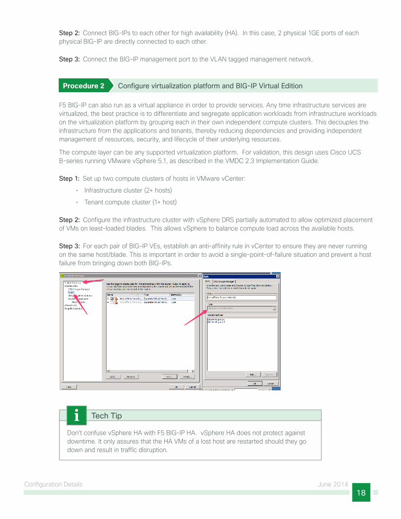
Step 3: For each pair of BIG-IP VEs, establish an anti-affinity rule in vCenter to ensure they are never running on the same host/blade. This is important in order to avoid a single-point-of-failure situation and prevent a host failure from bringing down both BIG-IPs.
Don’t confuse vSphere HA with F5 BIG-IP HA. vSphere HA does not protect against downtime. It only assures that the HA VMs of a lost host are restarted should they go down and result in traffic disruption.
Tech Tip

Configuration Details June 201419
The tenant compute cluster is used to host tenant/server VMs and does not require special consideration regarding anti-affinity. DRS is encouraged for intelligent management of compute, but it is not strictly necessary.
Configuring BIG-IP Pairs for Device High Availability
1. Configure HA interfaces on each BIG-IP pair
2. Establish device trust between BIG-IP pairs
PR
OC
ESS
BIG-IP HA features—such as connection mirroring (off by default), configuration synchronization, and network failover—allow core system services to be available for a BIG-IP device group in the event that a particular device group member becomes unavailable. The expectation is that in the event of a failure of a BIG-IP device, open connections can sustain via connection mirroring (if enabled) or would see a brief disconnection and re-establish to another device in the group.
For a full discussion regarding BIG-IP high availability options and considerations, refer to the documentation at the following locations:
http://support.f5.com/kb/en-us/solutions/public/14000/100/sol14135.html
http://support.f5.com/kb/en-us/products/big-ip_ltm.html
Procedure 1 Configure HA interfaces on each BIG-IP pair
Step 1: In Network > Trunks, create an LACP trunk between each BIG-IP pair for HA.
Step 2: In Network > VLANs, tag the HA network.
Detailed steps for this configuration are at the following location:
http://support.f5.com/kb/en-us/products/big-ip_ltm/manuals/product/tmos-implementations-11-4-0/24.html#conceptid
The following configuration snippet summaries these settings in the test environment:
net trunk HA_trunk {
interfaces {
1.1
1.2
}
lacp enabled
}
net vlan /Common/HA {
interfaces {
HA_trunk { }
}
tag 702
}

Configuration Details June 201420
Procedure 2 Establish device trust between BIG-IP pairs
Before any BIG-IP devices on a local network can synchronize configuration data or fail over to one another, they must establish a trust relationship known as device trust. Device trust between any two BIG-IP devices on the network is based on mutual authentication through the signing and exchange of x509 certificates.
Step 1: For each BIG-IP pair in each zone, in Device Management > Device Trust, create and associate each pair in a local trust domain. For detailed steps of this procedure, refer to the documentation at the following location:
http://support.f5.com/kb/en-us/products/big-ip_ltm/manuals/product/bigip-device-service-clustering-11-4-0.html
Step 2: Create Sync-Failover device group.
This step establishes failover capability between BIG-IP device pairs. If an active device in a Sync-Failover device group becomes unavailable, the configuration objects fail over to another member of the device group and traffic processing is unaffected. Connectivity between the BIG-IPs will use the VLAN-tagged LACP trunk established in the previous section.
In the Device Management section, create a new device group of type Sync-Failover, specifying this group to use Network Failover.
For detailed steps, see the documentation at the following location:
http://support.f5.com/kb/en-us/products/big-ip_ltm/manuals/product/bigip-device-service-clustering-11-4-0.html
Configuring BIG-IP Application Services
1. Persistent server load balancing for HTTP web traffic
2. Offloading client–side SSL encryption and load balancing web traffic
PR
OC
ESS
BIG-IP provides and applies application services and traffic management as traffic flows from clients to virtual servers (also called VIPs) and then to a pool of application servers and back. Validation was performed against both TCP and UDP application traffic, including HTTP, HTTPS, FTP, and DNS protocols, and leveraged several SLB features such as persistence, load balancing algorithms, health monitoring of servers, and SSL offload and acceleration in the VMDC 2.3 environment.
For additional information about other application delivery services and functionality within Local Traffic Manager, see the online documentation at: http://support.f5.com/kb/en-us/products/big-ip_ltm/
Reader Tip

Configuration Details June 201421
In most cases, the workflow for configuring BIG-IP services follows the general pattern:
1. Create one or more profiles that define the type of traffic, behavior, or other settings which are used by BIG-IP to affect managed traffic. For example, profiles are used to specify persistence, how particular protocols are handled, handling of SSL connections, and so on.
2. Create the pool of server resources that deliver an application service.
3. Select one or more Health Monitors, which monitor the availability of each member of the application pool.
4. Create a virtual server (VIP) that will front end the application service pool.
The following procedures outline the validated process for deploying server load balancing to a pool of servers using BIG-IP in VMDC.
Procedure 1 Persistent server load balancing for HTTP web traffic
Step 1: Under Local Traffic > Profiles > Persistence, create a new persistence profile, specifying the type Cookie and its parent, the default cookie profile. Select HTTP Cookie Insert for the Cookie Method, and then select the timeout of the cookie setting (in validation, 60 minutes was used for the timeout).

Configuration Details June 201422
In testing, cookie persistence was used; however, there are several alternative methods for achieving connection persistence. Cookie persistence directs session requests to the same server based on HTTP cookies that the BIG-IP system stores in the client’s browser.

Configuration Details June 201423
Step 2: Under Local Traffic >Pools, create a new server pool.
Step 3: Select the HTTP Health Monitor and add it to the active list of monitors for the newly created server pool.
Step 4: Select the Load Balancing Method (Example: Round Robin).
Step 5: Add pool members. A pool member refers to the IP address and port number pair of an application service (Example: 10.10.1.5:80)
Don’t confuse a server with a pool member. A single application server may have several services running on it—such as HTTP, SMTP, FTP—with each service a member of one or more pools.
Tech Tip

Configuration Details June 201424
Step 6: In Local Traffic > Virtual Servers, create a new virtual server for HTTP, specifying the IP address and type of service (for HTTP web traffic, this would be port 80).

Configuration Details June 201425
Step 7: In the HTTP Profile list, select an HTTP profile.
Step 8: Under the Resource tab, select the Default Pool. In this case, this would be the pool created in Step 2.

Configuration Details June 201426
Step 9: Select the cookie persistence profile created in Step 1 for the Default Persistence Profile.
Procedure 2 Offloading client–side SSL encryption and load balancing web traffic
Typically, securing a web application with SSL encryption requires deploying and managing certificates on every server of an application. This can be operationally expensive and error prone. BIG-IP physical appliances include specialized hardware, which provide accelerated performance and capacity for SSL key exchange and bulk encryption operations common to many applications. In addition, BIG-IP provides a single point-of-entry for client traffic to the application servers and can provide SSL encryption transparently without modification of application servers.
Given the HTTP server load balancing deployment configuration above, the following steps show how to enhance this configuration by providing SSL offload and acceleration on the BIG-IP. This validated implementation is an example of the ease in which one of many additional services and functionality can be added to an application with BIG-IP.
Step 1: Obtain an SSL certificate. This can be self-signed or purchased through an official certificate authority such as Verisign.

Configuration Details June 201427
Step 2: Under Local Traffic > Profiles > SSL > Client, create a new custom profile with the parent of clientssl.
Step 3: In the Configuration list, select Advanced, and then check the Custom checkbox for configuration.
Step 4: Select the Client Authentication settings as required.
You create a custom Client SSL profile when you want the BIG-IP system to terminate client-side SSL traffic for the purpose of:
• Authenticating and decrypting ingress client-side SSL traffic
• Re-encrypting egress client-side traffic
By terminating client-side SSL traffic, the BIG-IP system offloads these authentication and decryption/encryption functions from the destination server.

Configuration Details June 201428
Step 5: In Local Traffic > Virtual Servers, create a new virtual server for HTTPS, specifying the IP address and type of service (for HTTPS web traffic, this would be port 443).
Step 6: In the HTTP Profile list, select the HTTP profile.
Step 7: For the SSL Profile (Client) setting, select the Client SSL Profile from Step 2, move it to the Selected list, and click Finish.
Step 8: On the Resource tab, select the Default Pool. In this case, this would be the pool created in the previous procedure.
Step 9: For the Default Persistence Profile, select the cookie persistence profile created in the previous procedure.
The resulting virtual server will listen for HTTPS requests at port 443, decrypt traffic on the BIG-IP and load-balance them to one of the servers in the server pool, and then encrypt traffic as it returns to the client from BIG-IP.

Configuration Details June 201429
Configuring OSPF and Route Health Injection on BIG-IP
1. License advanced routing modules
2. Configure BIG-IP OSPF
3. Enable RHI on BIG-IPPR
OC
ESS
By adding F5 BIG-IP to the OSPF area 0, forming a neighbor relation between BIG-IP and the Nexus 7004, BIG-IP can advertise the availability of a VIP address throughout the intranet as a host route. This is known as Route Health Injection (RHI). The availability of a VIP is based on the status of attached virtual server. When a VIP become unavailable, BIG-IP withdraws the RHI information.
Procedure 1 License advanced routing modules
Step 1: In order to configure a BIG-IP system to add route entries into Traffic Management Microkernel and host route tables dynamically, BIG-IP needs to be licensed with the optional set of advanced routing modules. For details about BIG-IP licensing, refer to the documentation at the following location:
http://support.f5.com/kb/en-us/solutions/public/7000/700/sol7752.html?sr=37731073
Step 2: Enable the BIG-IP advanced routing module. For detailed steps, refer to the documentation at the following location:
http://support.f5.com/kb/en-us/products/big-ip_ltm/manuals/product/tmos-concepts-11-1-0/tmos_routes_dynamic.html#1225934

Configuration Details June 201430
Procedure 2 Configure BIG-IP OSPF
Step 1: Establish a neighbor relationship between F5 BIG-IP and Nexus 7004. The following is the BIG-IP OSPF configuration.
[root@f5-bigip5200-pub-2:Standby:In Sync] config # imishf5-bigip5200-pub-2.local[0]>enablef5-bigip5200-pub-2.local[0]#conf tf5-bigip5200-pub-2.local[0](config)#router ospff5-bigip5200-pub-2.local[0](config-router)#ip ospf priority 0f5-bigip5200-pub-2.local[0](config-router)#redistribute kernelf5-bigip5200-pub-2.local[0](config-router)#network 11.1.1.0/24 area 0f5-bigip5200-pub-2.local[0](config-router)#exit
It is not recommended that you use BIG-IP redundant pair as OSPF DR or BDR. To prevent OSPF instances configured on the units of a redundant system from becoming a DR or a BDR, we recommend that you configure an OSPF priority of 0 on every interface on which OSPF routing is enabled. For more information, see “Configuring the advanced routing modules” at the following location:
http://support.f5.com/kb/en-us/products/big-ip_ltm/manuals/product/bigip9_3mgmt/nsm_appendixc_zebos.html#1201655
Tech Tip
Step 2: Use the show ip ospf neighbor command to confirm that BIG-IP formed neighbors with the Nexus 7004.
f5-bigip5200-pub-2.1ocal[0]#show ip ospf neighbor
OSPF process 0:
Neighbor ID Pri State Dead Time Address Interface
10.2.5.2 1 Full/DR 00:00:39 11.1.1.2 external
10.2.5.3 1 Full/Backup 00:00:38 11.1.1.3 external
For complete BIG-IP advanced routing OSPF CLI information, refer to the documentation at the following location:
http://support.f5.com/content/kb/en-us/products/big-ip_ltm/manuals/related/ospf-commandreference-7-8-4/_jcr_content/pdfAttach/download/file.res/ospf-commandreference-7-8-4.pdf

Configuration Details June 201431
Procedure 3 Enable RHI on BIG-IP
Step 1: In order to have BIG-IP advertise VIP into the OSPF route domain, select the desired virtual server and the virtual address and enable Route Advertisement.
For details on F5 RHI configuration, refer to the documentation at the following locations:
• http://support.f5.com/kb/en-us/solutions/public/14000/200/sol14267.html?sr=37733034
• http://support.f5.com/kb/en-us/products/big-ip_ltm/manuals/product/tmos-concepts-11-1-0/tmos_routes_dynamic.html#1226094

Configuration Details June 201432
Creating Traffic Profile for QoS Passthrough
1. Create a custom TCP profileP
RO
CES
S
The BIG-IP local traffic management system can manage application-specific network traffic in a variety of ways, depending on the protocols and services being used. For example, you can configure the BIG-IP system to compress HTTP response data, or you can configure the system to authenticate SSL client certificates before passing requests on to a target server.
For each type of traffic that you want to manage, the BIG-IP system contains configuration tools that you can use to intelligently control the behavior of that traffic. These tools are called profiles. A profile is a system-supplied configuration tool that enhances your capabilities for managing application-specific traffic. More specifically, a profile is an object that contains user-configurable settings, with default values, for controlling the behavior of a particular type of network traffic, such as HTTP connections. After configuring a profile, you associate the profile with a virtual server. The virtual server then processes traffic according to the values specified in the profile. Using profiles enhances your control over managing network traffic and makes traffic-management tasks easier and more efficient.
This process walks you through the creation of a traffic profile for BIG-IP, specifically to ensure that QoS settings are preserved by BIG-IP in an VMDC environment.
Procedure 1 Create a custom TCP profile
The BIG-IP system includes one or more default profiles. A default profile is a system-supplied profile that contains default values for its settings. You can create custom profiles that inherit the properties of their parent and allow for custom settings.
TCP profiles are configuration tools that help you to manage TCP network traffic. Many of the configuration settings of TCP profiles are standard SYSCTL types of settings, while others are unique to the BIG-IP system. (This is similarly configurable with UDP as well).
You can explore the full set of TCP settings available in BIG-IP TCP Profiles at the following location:
http://support.f5.com/kb/en-us/products/big-ip_ltm/manuals/product/bigip9_3config/BIG_IP_LTM_9_3_Config_Guide-09-1.html#wp1211081
Reader Tip
In order to ensure traffic marked with QoS settings by devices upstream from the BIG-IP, such as the Cisco Nexus switch in our test environment, is respected by the BIG-IP, it is necessary to validate pass-through of the QoS identifiers in the TCP traffic profile.
Step 1: In the Local Traffic > Profiles > Protocol > TCP section, create new TCP profile from the default TCP profile, giving it a unique name (“TCP_Passthrough” in this design).

Configuration Details June 201433
Step 2: Set the IP ToS and Link QoS fields to Pass Through. This ensures QoS pass-through functionality.
The two TCP fields are:
• IP ToS—Specifies the Type of Service level in the IP header that the BIG-IP system assigns to packets when sending them to clients.
• Link QoS—Specifies the Quality of Service level in the Ethernet header that the BIG-IP system assigns to packets when sending them to clients.

Appendix A: Product List June 201434
Appendix A: Product ListThe following products and software versions were used in the testing of this design.
Functional Area Product Part Numbers Software Version
High Availability Server Load Balancing F5 BIG-IP Local Traffic Manager 5200V x 2 VE 1GB
11.4.1

Appendix B: Referenced Documents June 201435
Appendix B: Referenced Documents
Cisco VMDC DocumentationAll Cisco VMDC documentation:
• http://www.cisco.com/go/vmdc
Design Guides• VMDC 2.3 Design Guide:
http://www.cisco.com/en/US/docs/solutions/Enterprise/Data_Center/VMDC/2.3/design_guide/VMDC_2.3_DG.html
• VMDC 2.2 Design Guide:
http://www.cisco.com/en/US/docs/solutions/Enterprise/Data_Center/VMDC/2.2/design_guide/vmdcDesign22.html
• VMDC 2.1 Design Guide:
http://www.cisco.com/en/US/docs/solutions/Enterprise/Data_Center/VMDC/2.1/design_guide/vmdc21DesignGuide.html
F5 BIG-IP Documentation• About F5 BIG-IP
https://f5.com/products/modules/local-traffic-manager
http://www.f5.com/pdf/products/big-ip-virtual-editions-datasheet.pdf
• SOL14135: Defining network resources for BIG-IP high-availability features (11.x):
http://support.f5.com/kb/en-us/solutions/public/14000/100/sol14135.html

Americas HeadquartersCisco Systems, Inc.San Jose, CA
Asia Pacific HeadquartersCisco Systems (USA) Pte. Ltd.Singapore
Europe HeadquartersCisco Systems International BV Amsterdam,The Netherlands
Cisco has more than 200 offices worldwide. Addresses, phone numbers, and fax numbers are listed on the Cisco Website at www.cisco.com/go/offices.
ALL DESIGNS, SPECIFICATIONS, STATEMENTS, INFORMATION, AND RECOMMENDATIONS (COLLECTIVELY, “DESIGNS”) IN THIS MANUAL ARE PRESENTED “AS IS,” WITH ALL FAULTS. CISCO AND ITS SUPPLIERS DISCLAIM ALL WARRANTIES, INCLUDING, WITHOUT LIMITATION, THE WARRANTY OF MERCHANTABILITY, FITNESS FOR A PARTICULAR PURPOSE AND NONINFRINGEMENT OR ARISING FROM A COURSE OF DEALING, USAGE, OR TRADE PRACTICE. IN NO EVENT SHALL CISCO OR ITS SUPPLIERS BE LIABLE FOR ANY INDIRECT, SPECIAL, CONSEQUENTIAL, OR INCIDENTAL DAMAGES, INCLUDING, WITHOUT LIMITATION, LOST PROFITS OR LOSS OR DAMAGE TO DATA ARISING OUT OF THE USE OR INABILITY TO USE THE DESIGNS, EVEN IF CISCO OR ITS SUPPLIERS HAVE BEEN ADVISED OF THE POSSIBILITY OF SUCH DAMAGES. THE DESIGNS ARE SUBJECT TO CHANGE WITHOUT NOTICE. USERS ARE SOLELY RESPONSIBLE FOR THEIR APPLICATION OF THE DESIGNS. THE DESIGNS DO NOT CONSTITUTE THE TECHNICAL OR OTHER PROFESSIONAL ADVICE OF CISCO, ITS SUPPLIERS OR PARTNERS. USERS SHOULD CONSULT THEIR OWN TECHNICAL ADVISORS BEFORE IMPLEMENTING THE DESIGNS. RESULTS MAY VARY DEPENDING ON FACTORS NOT TESTED BY CISCO.
Any Internet Protocol (IP) addresses used in this document are not intended to be actual addresses. Any examples, command display output, and figures included in the document are shown for illustrative purposes only. Any use of actual IP addresses in illustrative content is unintentional and coincidental.
© 2013 Cisco Systems, Inc. All rights reserved.
Cisco and the Cisco logo are trademarks or registered trademarks of Cisco and/or its affiliates in the U.S. and other countries. To view a list of Cisco trademarks, go to this URL: www.cisco.com/go/trademarks. Third-party trademarks mentioned are the property of their respective owners. The use of the word partner does not imply a partnership relationship between Cisco and any other company. (1110R)
Please use the feedback form to send comments and suggestions about this guide.
Feedback
B-0000930-2 06/14