Cisco Routing and Swithing Quick Review Kit · By: Krzysztof Załęski CCIE R&S #24081 Cisco...
13
By: Krzysztof Załęski CCIE R&S #24081 Cisco Routing and Swithing Quick Review Kit ~ Legacy Technologies ~ ver. 20151025
Transcript of Cisco Routing and Swithing Quick Review Kit · By: Krzysztof Załęski CCIE R&S #24081 Cisco...

By: Krzysztof ZałęskiCCIE R&S #24081
Cisco Routing and SwithingQuick Review Kit
~ Legacy Technologies ~
ver. 20151025

3By Krzysztof Zaleski, CCIE #24081. This Booklet is available for free and can be freely distributed in a form as is. Selling is prohibited.
Copyright information
Cisco Routing and Switching Quick Review Kit – Legacy TechnologiesBy: Krzysztof Załęski, CCIE R&S #24081 http://ccie24081.wordpress.com [email protected]
ver. 20151025
This Booklet is NOT sponsored by, endorsed by or affiliated with Cisco Systems, Inc.
Cisco, Cisco Systems, CCIE, CCVP, CCIP, CCNP, CCNA, the Cisco Systems logo, the CCVP logo, the CCIE logo are trademarks or registered trademarks of Cisco Systems, Inc. in the United States and certain other countries.
All terms mentioned in this book, known to be trademarks or service marks belong to their appropriate right owners.
This Booklet is designed to help CCIE candidates to prepare themselves for the CCIE written and/or the lab exam. However, this is not a complete study reference. It is just a series of the author’s personal notes, written down during his pre-lab, and further studies, in a form of mind maps, based mainly on Cisco documentation. The main goal of this material is to provide quick and easy-to-skim method of refreshing one’s existing knowledge. All effort has been made to make this Booklet as precise and correct as possible, but no warranty is implied. CCIE candidates are strongly encouradged to prepare themselves using other comprehensive study materials like Cisco documentation, Cisco Press books, and other well-known vendors’ products, before going through this Booklet. The autor of this Booklet takes no responsibility, nor liablity to any person or entity with respect to loss of any information or failed tests or exams arising from the information contained in this Booklet.
This Booklet is available for free, and can be freely distributed in the form as is. Selling this Booklet in any printed or electroic form is prohibited. For the most recent version of this document, please visit http://ccie24081.wordpress.com

4By Krzysztof Zaleski, CCIE #24081. This Booklet is available for free and can be freely distributed in a form as is. Selling is prohibited.
Frame Relay..................5Zone Based Firewall..........8IOS IPS......................9Cat 3550 QoS................10RSVP........................11Other legacy QoS............12Multicast...................12RMON........................12FlexLink....................13WCCP........................13QinQ........................13
Table of Contents
(#) – enable command(G) – global command(IF) – interface command(RM) – route-map command(CM) – class-map command(PM) – policy-map commandetc
5By Krzysztof Zaleski, CCIE #24081. This Booklet is available for free and can be freely distributed in a form as is. Selling is prohibited.
FR
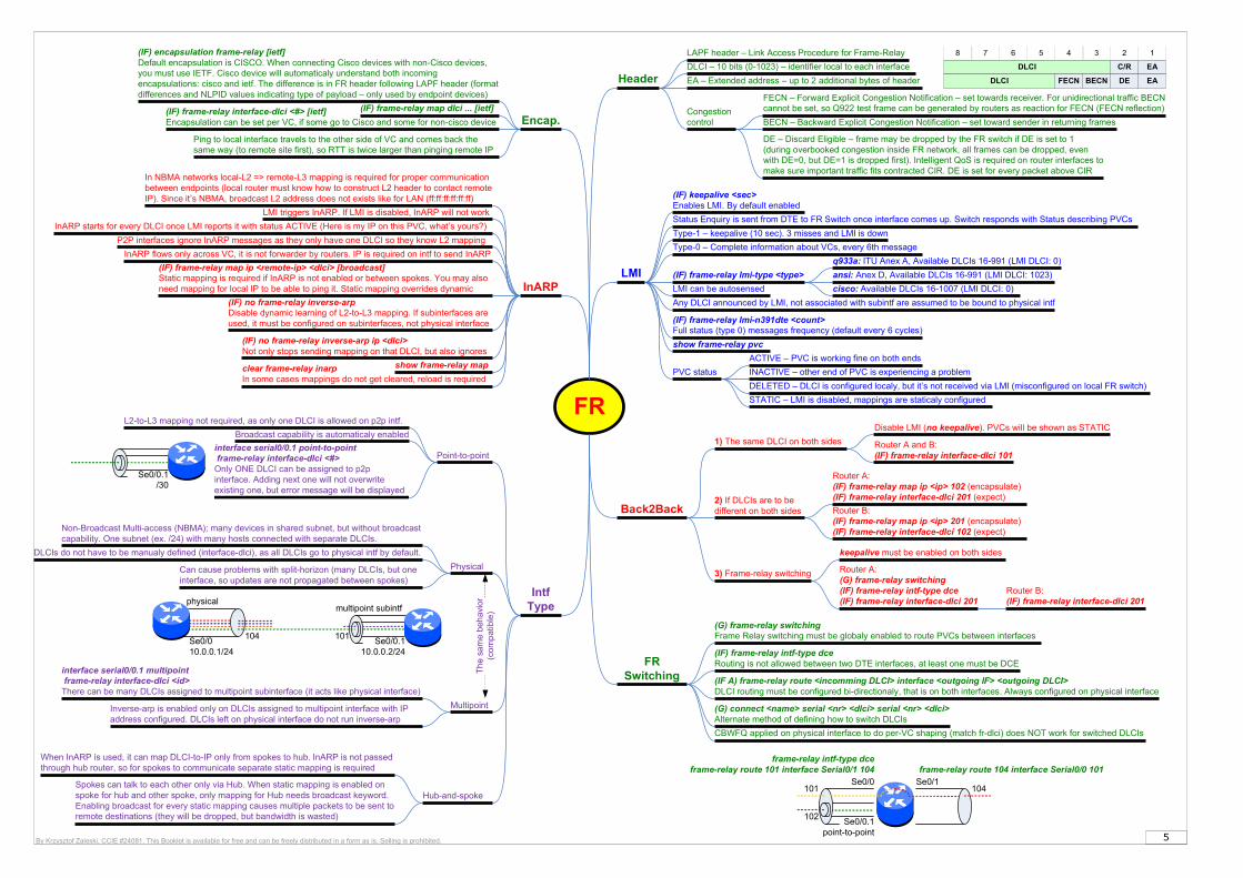
LMI
Status Enquiry is sent from DTE to FR Switch once interface comes up. Switch responds with Status describing PVCs
Type-1 – keepalive (10 sec). 3 misses and LMI is down
(IF) keepalive <sec>Enables LMI. By default enabled
Type-0 – Complete information about VCs, every 6th message
(IF) frame-relay lmi-type <type>
cisco: Available DLCIs 16-1007 (LMI DLCI: 0)
ansi: Anex D, Available DLCIs 16-991 (LMI DLCI: 1023)
q933a: ITU Anex A, Available DLCIs 16-991 (LMI DLCI: 0)
Header
LAPF header – Link Access Procedure for Frame-Relay
Encap.(IF) frame-relay map dlci ... [ietf](IF) frame-relay interface-dlci <#> [ietf]
Encapsulation can be set per VC, if some go to Cisco and some for non-cisco device
Any DLCI announced by LMI, not associated with subintf are assumed to be bound to physical intf
Intf Type
Point-to-point
Multipoint
L2-to-L3 mapping not required, as only one DLCI is allowed on p2p intf.
interface serial0/0.1 point-to-point frame-relay interface-dlci <#>Only ONE DLCI can be assigned to p2p interface. Adding next one will not overwrite existing one, but error message will be displayed
Broadcast capability is automaticaly enabled
interface serial0/0.1 multipoint frame-relay interface-dlci <id>There can be many DLCIs assigned to multipoint subinterface (it acts like physical interface)
Inverse-arp is enabled only on DLCIs assigned to multipoint interface with IP address configured. DLCIs left on physical interface do not run inverse-arp
Hub-and-spokeSpokes can talk to each other only via Hub. When static mapping is enabled on spoke for hub and other spoke, only mapping for Hub needs broadcast keyword. Enabling broadcast for every static mapping causes multiple packets to be sent to remote destinations (they will be dropped, but bandwidth is wasted)
When InARP is used, it can map DLCI-to-IP only from spokes to hub. InARP is not passed through hub router, so for spokes to communicate separate static mapping is required
InARP
LMI triggers InARP. If LMI is disabled, InARP will not work
clear frame-relay inarpIn some cases mappings do not get cleared, reload is required
P2P interfaces ignore InARP messages as they only have one DLCI so they know L2 mapping
InARP flows only across VC, it is not forwarder by routers. IP is required on intf to send InARP
(IF) frame-relay map ip <remote-ip> <dlci> [broadcast]Static mapping is required if InARP is not enabled or between spokes. You may also need mapping for local IP to be able to ping it. Static mapping overrides dynamic
(IF) no frame-relay inverse-arp ip <dlci>Not only stops sending mapping on that DLCI, but also ignores
(IF) no frame-relay inverse-arpDisable dynamic learning of L2-to-L3 mapping. If subinterfaces are used, it must be configured on subinterfaces, not physical interface
Back2Back
Router A:(IF) frame-relay map ip <ip> 102 (encapsulate)(IF) frame-relay interface-dlci 201 (expect)
1) The same DLCI on both sides
Disable LMI (no keepalive). PVCs will be shown as STATIC
2) If DLCIs are to be different on both sides Router B:
(IF) frame-relay map ip <ip> 201 (encapsulate)(IF) frame-relay interface-dlci 102 (expect)
3) Frame-relay switching Router A:(G) frame-relay switching(IF) frame-relay intf-type dce(IF) frame-relay interface-dlci 201
keepalive must be enabled on both sides
(IF) frame-relay lmi-n391dte <count>Full status (type 0) messages frequency (default every 6 cycles)
Router A and B:(IF) frame-relay interface-dlci 101
DLCI – 10 bits (0-1023) – identifier local to each interface
EA – Extended address – up to 2 additional bytes of header
FECN – Forward Explicit Congestion Notification – set towards receiver. For unidirectional traffic BECN cannot be set, so Q922 test frame can be generated by routers as reaction for FECN (FECN reflection)
BECN – Backward Explicit Congestion Notification – set toward sender in returning frames
DE – Discard Eligible – frame may be dropped by the FR switch if DE is set to 1 (during overbooked congestion inside FR network, all frames can be dropped, even with DE=0, but DE=1 is dropped first). Intelligent QoS is required on router interfaces to make sure important traffic fits contracted CIR. DE is set for every packet above CIR
(IF) encapsulation frame-relay [ietf]Default encapsulation is CISCO. When connecting Cisco devices with non-Cisco devices, you must use IETF. Cisco device will automaticaly understand both incoming encapsulations: cisco and ietf. The difference is in FR header following LAPF header (format differences and NLPID values indicating type of payload – only used by endpoint devices)
Congestion control
DLCI C/R EA
12345678
DLCI FECN BECN DE EA
Ping to local interface travels to the other side of VC and comes back the same way (to remote site first), so RTT is twice larger than pinging remote IP
Physical
DLCIs do not have to be manualy defined (interface-dlci), as all DLCIs go to physical intf by default.
Can cause problems with split-horizon (many DLCIs, but one interface, so updates are not propagated between spokes)
Se0/0.1/30
InARP starts for every DLCI once LMI reports it with status ACTIVE (Here is my IP on this PVC, what’s yours?)
Router B:(IF) frame-relay interface-dlci 201
FR Switching (IF A) frame-relay route <incomming DLCI> interface <outgoing IF> <outgoing DLCI>
DLCI routing must be configured bi-directionaly, that is on both interfaces. Always configured on physical interface
(G) frame-relay switchingFrame Relay switching must be globaly enabled to route PVCs between interfaces
frame-relay intf-type dceframe-relay route 101 interface Serial0/1 104 frame-relay route 104 interface Serial0/0 101
(IF) frame-relay intf-type dceRouting is not allowed between two DTE interfaces, at least one must be DCE
CBWFQ applied on physical interface to do per-VC shaping (match fr-dlci) does NOT work for switched DLCIs
LMI can be autosensed
PVC status
ACTIVE – PVC is working fine on both ends
INACTIVE – other end of PVC is experiencing a problem
DELETED – DLCI is configured localy, but it’s not received via LMI (misconfigured on local FR switch)
STATIC – LMI is disabled, mappings are staticaly configured
show frame-relay pvc
show frame-relay map
Non-Broadcast Multi-access (NBMA); many devices in shared subnet, but without broadcast capability. One subnet (ex. /24) with many hosts connected with separate DLCIs.
In NBMA networks local-L2 => remote-L3 mapping is required for proper communication between endpoints (local router must know how to construct L2 header to contact remote IP). Since it’s NBMA, broadcast L2 address does not exists like for LAN (ff:ff:ff:ff:ff:ff)
Se0/010.0.0.1/24
Se0/0.110.0.0.2/24
101104
physicalmultipoint subintf
(G) connect <name> serial <nr> <dlci> serial <nr> <dlci>Alternate method of defining how to switch DLCIs
Se0/0.1point-to-point
101
102
Se0/0 Se0/1104
6By Krzysztof Zaleski, CCIE #24081. This Booklet is available for free and can be freely distributed in a form as is. Selling is prohibited.
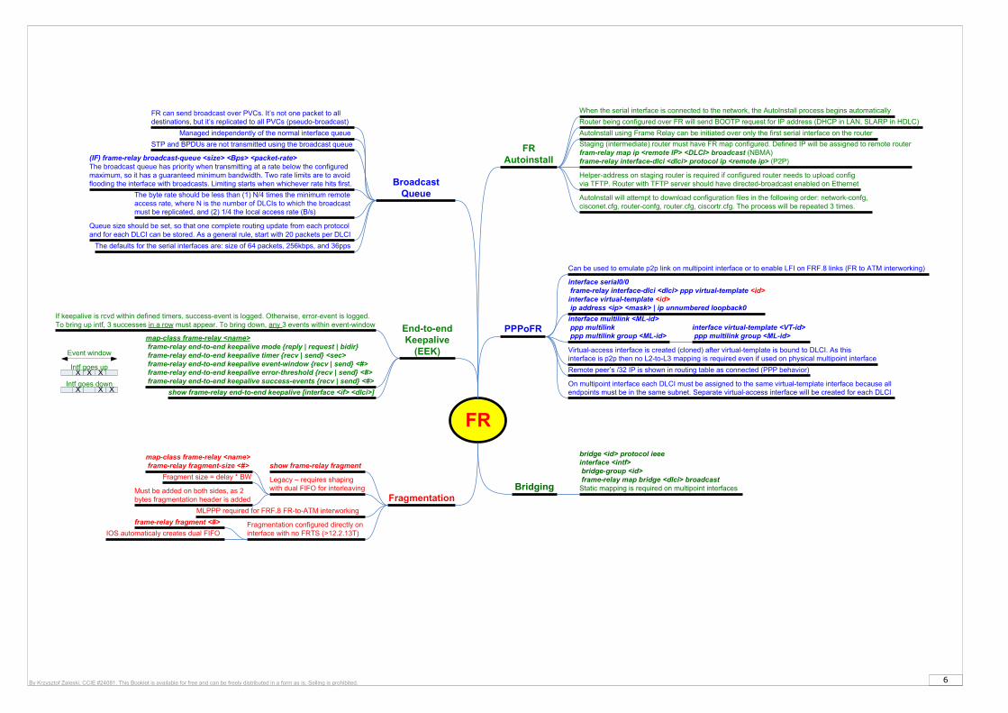
FR
Fragmentation
Legacy – requires shaping with dual FIFO for interleaving
map-class frame-relay <name> frame-relay fragment-size <#>
Must be added on both sides, as 2 bytes fragmentation header is added
Fragmentation configured directly on interface with no FRTS (>12.2.13T)
frame-relay fragment <#>
IOS automaticaly creates dual FIFO
MLPPP required for FRF.8 FR-to-ATM interworking
show frame-relay fragment
End-to-end Keepalive
(EEK)
map-class frame-relay <name> frame-relay end-to-end keepalive mode {reply | request | bidir} frame-relay end-to-end keepalive timer {recv | send} <sec> frame-relay end-to-end keepalive event-window {recv | send} <#> frame-relay end-to-end keepalive error-threshold {recv | send} <#> frame-relay end-to-end keepalive success-events {recv | send} <#>
PPPoFR
Virtual-access interface is created (cloned) after virtual-template is bound to DLCI. As this interface is p2p then no L2-to-L3 mapping is required even if used on physical multipoint interface
interface serial0/0 frame-relay interface-dlci <dlci> ppp virtual-template <id>interface virtual-template <id> ip address <ip> <mask> | ip unnumbered loopback0
Remote peer’s /32 IP is shown in routing table as connected (PPP behavior)
Bridging
bridge <id> protocol ieeeinterface <intf> bridge-group <id> frame-relay map bridge <dlci> broadcastStatic mapping is required on multipoint interfaces
If keepalive is rcvd within defined timers, success-event is logged. Otherwise, error-event is logged. To bring up intf, 3 successes in a row must appear. To bring down, any 3 events within event-window
On multipoint interface each DLCI must be assigned to the same virtual-template interface because all endpoints must be in the same subnet. Separate virtual-access interface will be created for each DLCI
interface multilink <ML-id> ppp multilink ppp multilink group <ML-id>
interface virtual-template <VT-id> ppp multilink group <ML-id>
Fragment size = delay * BW
Broadcast Queue
Managed independently of the normal interface queue
STP and BPDUs are not transmitted using the broadcast queue
(IF) frame-relay broadcast-queue <size> <Bps> <packet-rate>The broadcast queue has priority when transmitting at a rate below the configured maximum, so it has a guaranteed minimum bandwidth. Two rate limits are to avoid flooding the interface with broadcasts. Limiting starts when whichever rate hits first.
Can be used to emulate p2p link on multipoint interface or to enable LFI on FRF.8 links (FR to ATM interworking)
X X X
X X X
Event window
Intf goes up
Intf goes down
FR Autoinstall
Router being configured over FR will send BOOTP request for IP address (DHCP in LAN, SLARP in HDLC)
Staging (intermediate) router must have FR map configured. Defined IP will be assigned to remote routerfram-relay map ip <remote IP> <DLCI> broadcast (NBMA)frame-relay interface-dlci <dlci> protocol ip <remote ip> (P2P)
Helper-address on staging router is required if configured router needs to upload config via TFTP. Router with TFTP server should have directed-broadcast enabled on Ethernet
Queue size should be set, so that one complete routing update from each protocol and for each DLCI can be stored. As a general rule, start with 20 packets per DLCI
The defaults for the serial interfaces are: size of 64 packets, 256kbps, and 36pps
The byte rate should be less than (1) N/4 times the minimum remote access rate, where N is the number of DLCIs to which the broadcast must be replicated, and (2) 1/4 the local access rate (B/s)
FR can send broadcast over PVCs. It’s not one packet to all destinations, but it’s replicated to all PVCs (pseudo-broadcast)
AutoInstall will attempt to download configuration files in the following order: network-confg, cisconet.cfg, router-confg, router.cfg, ciscortr.cfg. The process will be repeated 3 times.
AutoInstall using Frame Relay can be initiated over only the first serial interface on the router
When the serial interface is connected to the network, the AutoInstall process begins automatically
show frame-relay end-to-end keepalive [interface <if> <dlci>]
7By Krzysztof Zaleski, CCIE #24081. This Booklet is available for free and can be freely distributed in a form as is. Selling is prohibited.
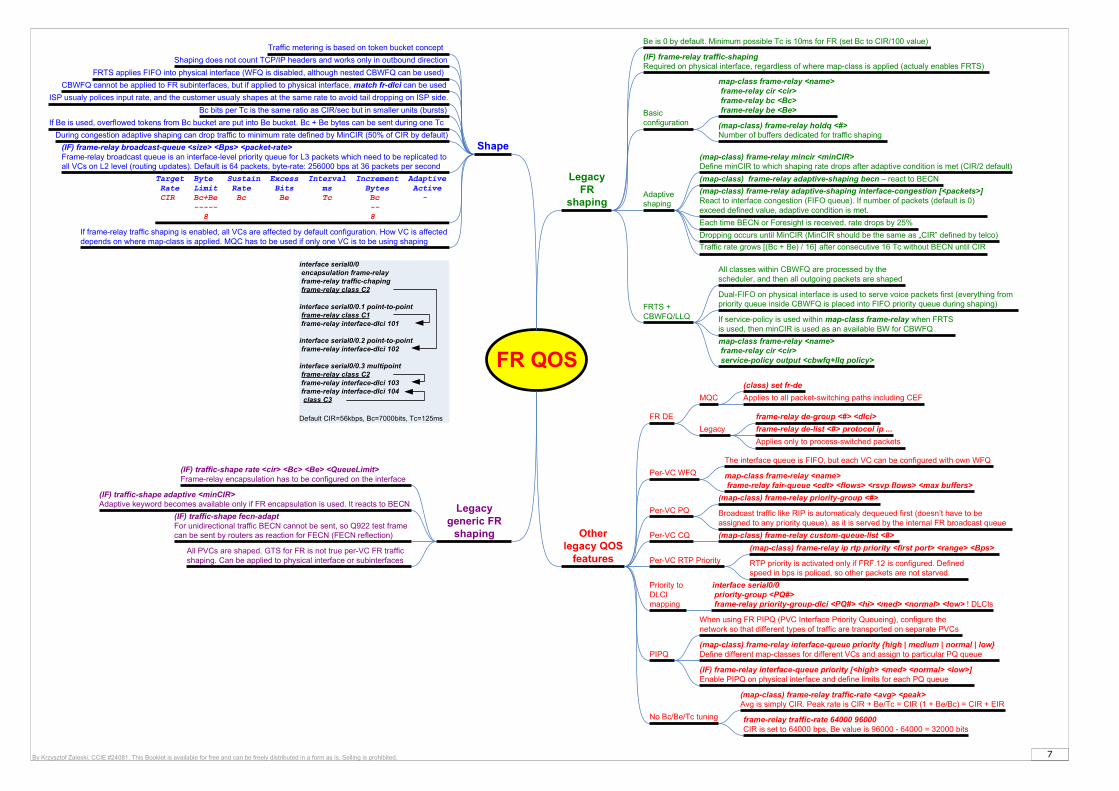
FR QOS
FR DE
frame-relay de-list <#> protocol ip ...
frame-relay de-group <#> <dlci>
Legacy
MQC
(class) set fr-de
Applies to all packet-switching paths including CEF
Applies only to process-switched packets
(IF) traffic-shape rate <cir> <Bc> <Be> <QueueLimit>Frame-relay encapsulation has to be configured on the interface
Legacy generic FR
shaping
(IF) traffic-shape fecn-adaptFor unidirectional traffic BECN cannot be sent, so Q922 test frame can be sent by routers as reaction for FECN (FECN reflection)
(IF) traffic-shape adaptive <minCIR>Adaptive keyword becomes available only if FR encapsulation is used. It reacts to BECN
All PVCs are shaped. GTS for FR is not true per-VC FR traffic shaping. Can be applied to physical interface or subinterfaces
Other legacy QOS
features
(map-class) frame-relay traffic-rate <avg> <peak>Avg is simply CIR. Peak rate is CIR + Be/Tc = CIR (1 + Be/Bc) = CIR + EIR
map-class frame-relay <name> frame-relay fair-queue <cdt> <flows> <rsvp flows> <max buffers>
(map-class) frame-relay priority-group <#>
Per-VC WFQ
The interface queue is FIFO, but each VC can be configured with own WFQ
Per-VC PQ
(map-class) frame-relay custom-queue-list <#>Per-VC CQ
Broadcast traffic like RIP is automaticaly dequeued first (doesn’t have to be assigned to any priority queue), as it is served by the internal FR broadcast queue
Per-VC RTP Priority
(map-class) frame-relay ip rtp priority <first port> <range> <Bps>
RTP priority is activated only if FRF.12 is configured. Defined speed in bps is policed, so other packets are not starved.
PIPQ
When using FR PIPQ (PVC Interface Priority Queueing), configure the network so that different types of traffic are transported on separate PVCs
(map-class) frame-relay interface-queue priority {high | medium | normal | low}Define different map-classes for different VCs and assign to particular PQ queue
(IF) frame-relay interface-queue priority [<high> <med> <normal> <low>]Enable PIPQ on physical interface and define limits for each PQ queue
Priority to DLCI mapping
interface serial0/0 priority-group <PQ#> frame-relay priority-group-dlci <PQ#> <hi> <med> <normal> <low> ! DLCIs
No Bc/Be/Tc tuning frame-relay traffic-rate 64000 96000CIR is set to 64000 bps, Be value is 96000 - 64000 = 32000 bits
map-class frame-relay <name> frame-relay cir <cir> service-policy output <cbwfq+llq policy>
(IF) frame-relay broadcast-queue <size> <Bps> <packet-rate>Frame-relay broadcast queue is an interface-level priority queue for L3 packets which need to be replicated to all VCs on L2 level (routing updates). Default is 64 packets, byte-rate: 256000 bps at 36 packets per second
Be is 0 by default. Minimum possible Tc is 10ms for FR (set Bc to CIR/100 value)
If frame-relay traffic shaping is enabled, all VCs are affected by default configuration. How VC is affected depends on where map-class is applied. MQC has to be used if only one VC is to be using shaping
CBWFQ cannot be applied to FR subinterfaces, but if applied to physical interface, match fr-dlci can be used
Legacy FR
shaping
map-class frame-relay <name> frame-relay cir <cir> frame-relay bc <Bc> frame-relay be <Be>
FRTS applies FIFO into physical interface (WFQ is disabled, although nested CBWFQ can be used)
Shape
Dual-FIFO on physical interface is used to serve voice packets first (everything from priority queue inside CBWFQ is placed into FIFO priority queue during shaping)FRTS +
CBWFQ/LLQ
All classes within CBWFQ are processed by the scheduler, and then all outgoing packets are shaped
(IF) frame-relay traffic-shapingRequired on physical interface, regardless of where map-class is applied (actualy enables FRTS)
Adaptive shaping
(map-class) frame-relay mincir <minCIR>Define minCIR to which shaping rate drops after adaptive condition is met (CIR/2 default)
(map-class) frame-relay adaptive-shaping becn – react to BECN
(map-class) frame-relay adaptive-shaping interface-congestion [<packets>]React to interface congestion (FIFO queue). If number of packets (default is 0) exceed defined value, adaptive condition is met.
Basic configuration
Each time BECN or Foresight is received, rate drops by 25%
Dropping occurs until MinCIR (MinCIR should be the same as „CIR” defined by telco)
Traffic rate grows [(Bc + Be) / 16] after consecutive 16 Tc without BECN until CIR
If service-policy is used within map-class frame-relay when FRTS is used, then minCIR is used as an available BW for CBWFQ
During congestion adaptive shaping can drop traffic to minimum rate defined by MinCIR (50% of CIR by default)
Target Byte Sustain Excess Interval Increment Adaptive Rate Limit Rate Bits ms Bytes Active CIR Bc+Be Bc Be Tc Bc - ----- -- 8 8
ISP usualy polices input rate, and the customer usualy shapes at the same rate to avoid tail dropping on ISP side.
Bc bits per Tc is the same ratio as CIR/sec but in smaller units (bursts)
If Be is used, overflowed tokens from Bc bucket are put into Be bucket. Bc + Be bytes can be sent during one Tc
Shaping does not count TCP/IP headers and works only in outbound direction
Traffic metering is based on token bucket concept
(map-class) frame-relay holdq <#>Number of buffers dedicated for traffic shaping
interface serial0/0 encapsulation frame-relay frame-relay traffic-chaping frame-relay class C2
interface serial0/0.1 point-to-point frame-relay class C1 frame-relay interface-dlci 101
interface serial0/0.2 point-to-point frame-relay interface-dlci 102
interface serial0/0.3 multipoint frame-relay class C2 frame-relay interface-dlci 103 frame-relay interface-dlci 104 class C3
Default CIR=56kbps, Bc=7000bits, Tc=125ms

8By Krzysztof Zaleski, CCIE #24081. This Booklet is available for free and can be freely distributed in a form as is. Selling is prohibited.
ZBF
Zones
A zone is a group of interfaces that have similar functions or features from security perspective.
Traffic between interfaces in the same zone is allowed
When interface is added to a zone, all traffic is dropped. To allow traffic a pair of zones must be defined with appropriate policy (pass, inspect). All interfaces are supported (physical, virtual, logical)
When ZBFW is configured all the interfaces must be a member of one security zone or another. No traffic will pass to an interface which is not assigned to any zone
ZBFW
Z2Z1
Requires policy
Allowed
Denied Denied
Allowed
A zone-pair allows to specify a unidirectional firewall policy between two security zones. However it is not required to define policy for returning traffic, which is allowed by a statefull firewall operation
Traffic generated by the router or to the router is not a subject to any policy. A self-zone can be defined (no interfaces are assigned to it) to create policy for router traffic (not a traffic flowing through a router). Policing is not allowed in policies that are attached to zone-pairs involving a self-zone
Inspection can be configured per-flow. Not all traffic flowing through an interface must be inspected
Inspect
ACLs applied to interfaces that are members of zones are processed before the policy is applied on the zone-pair
Inspection configuration is based on class-map (type inspect), policy-map, service-policy, just like in QoS
NBAR is not available for bridged packets (transparent firewall between bridged interface)
The policy map can include class maps only of the same type
Application inspection
A Layer 7 policy map must be contained in a Layer 3 or Layer 4 policy map; it cannot be attached directly to a target
FastTrack, eDonkey, Gnutella, H.323, HTTP, Kazaa, ICQ, MSN IM, POP3, SIP, SMTP, ...
There is always a class-default at the end. Default action is drop. It can be changed to inspect
Param. maps
Inspect
Out-of-Order
Default behaviour is to drop packets arriving out of order
Not supported in SMTP, as SMTP supports masking action that requires packet modification
OoO packet processing is enabled by default when a L7 policy is configured for DPI
Class map
(G) class-map type inspect [match-any | match-all] <name>Creates a Layer 3 or Layer 4 inspect type class map
Verify
show policy-map type inspect zone-pair session
match class-map <name>Classes can be used to define hierarchical match
match protocol <name> [signature]Only Cisco IOS stateful packet inspection supported protocols can be used as match criteria in inspect type class maps. Signature-based p2p packets can be matched
match access-group {<acl> | name <acl-name>}Match based on the ACL name or number
Policy map
policy-map type inspect <name> class type inspect <name>Creates a Layer 3 and Layer 4 inspect type policy map
police rate <bps> burst <size>Policing (rate-limiting) can only be specified in L3/L4 policy maps. Inspection must be enabled.
drop [log] - Drop packetspassAllow packets. No statefull checking capability, requires reflexive ACL for returning traffic
service-policy type inspect <name>There can be a maximum of two levels in a hierarchical inspect service-policy. Parameters in the lower levels override those in the top levels
urlfilter <parameter-map-name>Enables Cisco IOS firewall URL filtering clear zone-pair inspect sessions
Changes to the parameter map are not reflected on connections already established through the firewall
parameter-map type inspect <name>
alert {on | off} ! Alert messages are displayed on the consoleaudit-trail {on | off}
dns-timeout <sec>
max-incomplete {low <#> | high <#>}
tcp finwait-time <sec>
{tcp | udp | icmp} idle-time <sec>
tcp max-incomplete host <threshold> [block-time <minutes>]
tcp synwait-time <sec>
tcp window-scale-enforcement looseDisables the window scale option check
URL filter
parameter-map type urlfilter <name> - hidden since 12.4(20)T
allow-mode {on | off}Turns on or off the default mode of the filtering algorithm
cache <#>Controls how the URL filter handles the cache it maintains of HTTP servers
exclusive-domain {deny | permit} <domain-name>Firewall does not send DNS request for traffic destined for those domains
max-request <#>
max-resp-pak <number-of-requests>Maximum number of HTTP responses that the Cisco IOS firewall can keep in its packet buffer
server vendor {n2h2 | websense} {<ip> | <hostname> [port <#>]} [outside] [log] [retrans <count>] [timeout <sec>]Specifies the URL filtering server
source-interface <if>
inspect [<parameter-map-name>]Enables Cisco IOS stateful packet inspection. Anticipate returning traffic according to session information
one-minute {low <#> | high <#>}
sessions maximum <#>
Protocol specific
parameter-map type protocol-info <name>Protocol-specific parameter maps can be created only for Instant Messenger applications
server {name <string> [snoop] | ip {<ip> | range <start> <end>}This command can be defined multiple times to match many servers
parameter-map type ooo globalOoO paramter map defines global operations for all interfaces
tcp reassembly alarm {on | off}
tcp reassembly memory limit <limit>OoO buffer size
tcp reassembly queue length <#>OoO queue
tcp reassembly timeout <sec>
(G) class-map type inspect <protocol> [match-any | match-all] <name>(G) policy-map type inspect <protocol> <name>
(G) parameter-map type urlfpolicy {local | n2h2 | websense} <name>(G) class-map type urlfilter {<name> | {n2h2 | websense} <name>}(G) policy-map type inspect urlfilter <name>
An interface cannot be part of a zone and legacy inspect policy at the same time, but legacy FW is supported at the same time on different interfaces. Plain ACLs are supported on ZBF interfaces: „in” is served before ZBF, „out” - after ZBF
(G) zone security <name> ! create a zone
zone-pair security <pair-name> {source <zone-name> | self] destination [self | <zone-name>] service-policy type inspect <map-name> ! if policy map is not applied, traffic is dropped by default
(IF) zone-member security <zone-name>
Self-zone is router itself. Traffic cannot be policed
ZBF is VRF-aware. It deduces VRF from target zone defined in the policy.
Source Intf Zone
---
ZoneA
ZoneA
---
ZoneA
ZoneA
ZoneA
---
ZoneA
Dest Intf Zone
---
ZoneA
ZoneB
ZoneB
ZoneB
Zone prair exists
C3PL policy exists
Result
--- ---
Not allowed! ---
PASS
PASS
---
---
---
---
DROP
DROP
---No
NoYes
Yes Yes
DROP
DROP
C3PL action
SELF
SELF
SELF
SELF
SELF
SELF
ZoneA
ZoneA
ZoneA
ZoneA
ZoneA
ZoneA
No
Yes
Yes
No
Yes
Yes
No
Yes
No
Yes
---
---
PASS
PASS
C3PL action
PASS
PASS
C3PL action
Passin
g t
raffic
Ro
ute
r tr
affic

9By Krzysztof Zaleski, CCIE #24081. This Booklet is available for free and can be freely distributed in a form as is. Selling is prohibited.
IOS IPS
Features
Actions: Send an alarm to a syslog server, Drop the packet, Reset the connection, Deny traffic from the source IP address of the attacker for a specified amount of time, Deny traffic on the connection for which the signature was seen for a specified amount of time
In-line intrusion detection sensor, watching packets and sessions as they flow through the router and scanning each packet to match any of the Cisco IOS IPS signatures
A transparent Cisco IOS IPS device acts as a Layer 3 (only) IPS between bridged interfaces. A transparent IPS device supports a BVI for routing.
Cisco IOS IPS 5.x format signatures are not backward compatible with Cisco IOS IPS 4.x SDFs.
Parallel Signature Scanning Engine is used to scan for multiple patterns within a signature microengine (SME) at any given time (no serial processing)
Signatures are loaded and complied onto a router using SDF (signature definition file). Some files are always available on flash with IOS IPS. If neither file is specified, IOS uses internal built-in signatures
attack-drop.sdf file (83 signatures) is used for routers with less than 128MB memory
128MB.sdf (about 300 signatures) is used for routers with 128 MB or more memory
256MB.sdf (about 500 signatures) is used for routers with 256 MB or more memory
If you want to configure transparent IPS, you must configure a bridge group before loading IPS onto a device
Signatures version 4
(G) ip ips sdf location <url>Specifies the location in which the router will load the SDF. If this command is not issued, the router will load buil-in SDF
(G) ip ips name <name> [list <acl>]Creates an IPS rule. Only packets that are permitted via ACL (if used) will be scanned by IPS
(G) ip ips signature <id> [:<sub-id>] {delete | disable | list <acl>}
(G) ip ips deny-action ips-interfaceCreates an ACL filter for the deny actions on the IPS interface rather than the ingress interface. Use this command only if at least one signature is configured to use the supported deny actions, if the input interface is configured for load balancing, and if IPS is configured on the output interface
(IF) ip ips <name> {in | out}Applies an IPS rule at an interface and automatically loads the signatures and builds the signature engines
Verify
show ip ips configuration
(G) no ip ips location in builtinDon’t load built-in signatures if specified signature file does not exist. IPS will be disabled if no signatures can be enabled
(G) ip ips fail closedDrop all packets until the signature engine is built and ready to scan traffic. If this command is not issued, all packets will be passed without scanning if the signature engine fails to build
show ip ips signatures [detailed]
copy [/erase] <url> ips-sdfMerge SDF (attack-drop.sdf) with built-in signatures. The SDF will merge with the signatures that are already loaded in the router, unless the /erase keyword is issued (replaces signatures)
copy ips-sdf <url>Save current copy of signatures
Reporting
Reporting can be done using syslog or SDEE (Security Device Event Exchange)
(G) ip ips notify [log | sdee]SDEE is an application-level protocol used to exchange IPS messages between IPS clients and IPS servers. It is always running but it does not receive and process events from IPS unless SDEE notification is enabled. To use SDEE, the HTTP server must be enabled
(G) ip sdee events <#>When SDEE notification is disabled, all stored events are lost. The buffer is circular (default is 200 events)
ip sdee subscriptions <1-3>Maximum number of SDEE subscriptions that can be open simultaneously
show ip sdee
Cisco IPS appliances and Cisco IOS IPS with Cisco 5.x format signatures operate with signature categories. As of Cisco IOS Release 12.4(11)T, SDFs are no longer used by Cisco IOS IPS
Signaturesversion 5
Signatures are pregrouped into hierarchical categories. Signature can belong to more than one category
(G) ip ips config location <url>Routers access signature definition information via a directory that contains three configuration files (compressed xml) - the default configuration, the delta configuration, and the SEAP configuration. You must specify a location, otherwise, the signature package will not be saved
SEAP is the control unit responsible for coordinating the data flow of a signature event. It allows for advanced filtering and signature overrides on the basis of the Event Risk Rating (ERR) feedback. ERR is used to control the level in which a user chooses to take actions in an effort to minimize false positives
Signatures once stored in NVRAM, will now be stored in the delta configuration file
Attack Severity Rating (ASR) - hard-coded: high, medium, low, and informational
Signature Fidelity Rating (SFR) - confidence level of detecting a true positive
ip ips autoupdate occur-at <min:hour> <date> <day> username <name> password <password> utl <url>Version 5 supports automatic updates from local servers (Basic and Advanced sig. files). NTP is recommended
show ip ips signature count
(G) copy <url> idconfSignatures are loaded into the scanning table on the basis of importance (severity, fidelity rating, and time lapsed since signatures were last released). After the package is loaded, all signature information is saved to the specified location
Per-signatureip ips signature-definition signature <id> [:<sub-id>] engine event-action <action> alert-severity <severity> fidelity-rating <rating> status enabled {true | false}
Enevt action can be: deny-attacker-inline, deny-connection-inline, deny-packet-inline, produce-alert, reset-tcp-connection
Tuning
Per-categoryip ips signature-category category <category> [<subcategory>] event-action <action> alert-severity <severity> fidelity-rating <rating> enabled {true | false} retired {true | false}
(G) ip ips inherit-obsolete-tuningsWhen new signatures are replacing older signatures they can inherit the event-action and enabled parameters of the obsoleted ones
(G) ip ips memory threshold <MB>When a router starts, 90% of the available memory is allocated to IPS. Remaining 10% is called IPS Memory Threshold and is unavailable to the IPS
ip ips event-action-rules target-value {mission-critical | high | medium | low} target-address <ip> [/<nn> | to <ip>]Target Value Rating (TVR) - Allows developing security policies that can be more strict for some resources. Changes to the target value rating is not shown in the running config because the changes are recorded in the seap-delta.xml file
show ip ips auto-update
(IF) ip ips <name> {in | out}Applies an IPS rule at an interface and automatically loads the signatures and builds the signature engines

10By Krzysztof Zaleski, CCIE #24081. This Booklet is available for free and can be freely distributed in a form as is. Selling is prohibited.
3550QoS
Ingress Queue
Egress queue
4 queues with classification based on COS (Q4 can be PQ)
Each Q has 2 thresholds defined as % of Q len. Linear drop between T1 and T2 from 0 to 100%
wrr-queue dscp-map <threshold> <dscp> …By default all 64 DSCPs are mapped to T1
wrr-queue random-detect max-threshold <queue> <t1> <t2>
1x FIFO; 8 policers per FE, 128 policers per GE
Per-port Per-VLAN
You cannot configure both port-based classification and VLAN-based classification at the same time. Hirarchical class-maps are required
Within a policy map, when you use the match vlan <vlan-list> command, all other class maps must use the match vlan <vlan-list> command
class-map match-any COMMON match ip dscp 24 match ip address 100class-map match-all vlan_class match vlan 10 20-30 40 match class-map COMMON
2. Mapping CoS Values to Select Egress Queues (IF) wrr-queue cos-map <queue-id> <cos1> ... <cos8>
Egress Queue Size Ratios(IF) wrr-queue queue-limit <w1> <w2> <w3> <w4>Relative size difference in the numbers show the relative differences in the queue sizes
wrr-queue threshold <queue> <t1> <t2>
Enable expedite queue
(IF) priority-queue outWRR weight and queue size ratios are affected because there is one fewer queue participating in WRR. This means that weight4 in the wrr-queue bandwidth command is ignored (not used in the ratio calculation)
3. Allocating Bandwidth among Egress Queues
(IF) wrr-queue bandwidth <w1> <w2> <w3> <w4>Ratio of weights is the ratio of frequency in which WRR scheduler dequeues packets from each queue
1. Configuring Minimum-Reserve Levels on FE ports
(IF) wrr-queue min-reserve <queue-id> <MRL level>
(G) mls qos min-reserve <level> <packets>
There are 8 possible levels. By default, queue 1 selects level 1, queue 2 selects level 2, queue 3 selects level 3, and queue 4 selects level 4
show mls qos interface <if> queueing
WRED on GE ports
You can create a policer that is shared by multiple traffic classes within the same policy map. However, you cannot use the aggregate policer across different policy maps or interfaces
mls qos aggregate-police <name> <rate-bps> <burst-byte> exceed-action {drop | policed-dscp-transmit}
class <name> police aggregate <name>
Aggregate policer
76
0/1 0/24... FE/GE ...
Q1 Q2 Q3 Q4
Memory bufferswrr-queue queue-limit <w1> <w2> <w3> <w4>
0,12,34,5
Priority queue(IF) priority-queue out
6,7COS/DSCP
Remainint BW is shared among other queues (W4 is ignored in ration calculations)wrr-queue bandwidth <w1> <w2> <w3> <w4>
OUTPUT
Min-reserve buffers(IF) wrr-queue min-reserve <queue-id> <MRL level>
7642MRL
wrr-queue cos-map <queue-id> <cos1> ... <cos8>
Min-reserve buffersmls qos min-reserve <level> <packets>
10
MRL
Buffer size 20 30 40 50 60 70 80
1 2 3 4 5 6 7 8
Tail-drop thresholdswrr-queue threshold <queue> <t1> <t2>
wrr-queue dscp-map <threshold> <dscp1-8>
WRED thresholdswrr-queue random-detect max-threshold <queue> <t1> <t2>
GE interfaces ONLY
11By Krzysztof Zaleski, CCIE #24081. This Booklet is available for free and can be freely distributed in a form as is. Selling is prohibited.
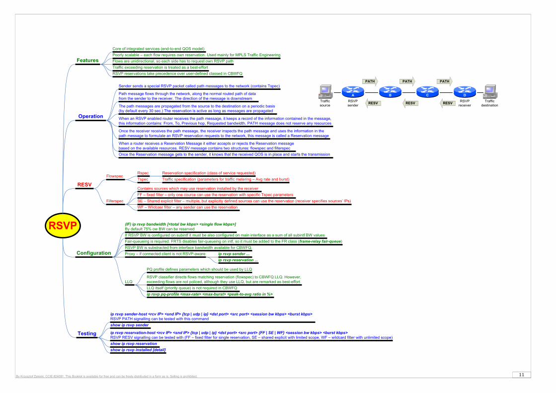
RSVP
Operation
Sender sends a special RSVP packet called path messages to the network (contains Tspec)
Path message flows through the network, along the normal routed path of data from the sender to the receiver. The direction of the message is downstream
The path messages are propagated from the source to the destination on a periodic basis (by default every 30 sec.) The reservation is active as long as messages are propagated
When an RSVP enabled router receives the path message, it keeps a record of the information contained in the message, this information contains: From, To, Previous hop, Requested bandwidth. PATH message does not reserve any resources
Once the receiver receives the path message, the receiver inspects the path message and uses the information in the path message to formulate an RSVP reservation requests to the network, this message is called a Reservation message
When a router receives a Reservation Message it either accepts or rejects the Reservation message based on the available resources. RESV message contains two structures: flowspec and filterspec
Once the Reservation message gets to the sender, it knows that the received QOS is in place and starts the transmission
Configuration
(IF) ip rsvp bandwidth [<total bw kbps> <single flow kbps>]By default 75% ow BW can be reserved
ip rsvp sender-host <rcv IP> <snd IP> {tcp | udp | ip} <dst port> <src port> <session bw kbps> <burst kbps>RSVP PATH signalling can be tested with this command
show ip rsvp sender
ip rsvp reservation-host <rcv IP> <snd IP> {tcp | udp | ip} <dst port> <src port> {FF | SE | WF} <session bw kbps> <burst kbps>RSVP RESV signalling can be tested with (FF – fixed filter for single reservation, SE – shared explicit with limited scope, WF – wildcard filter with unlimited scope)
show ip rsvp reservation
Testing
Proxy – if connected client is not RSVP-aware ip rsvp sender ...
ip rsvp reservation ...
If RSVP BW is configured on subintf it must be also configured on main interface as a sum of all subintf BW values
Fair-queueing is required. FRTS disables fair-queueing on intf, so it must be added to the FR class (frame-relay fair-queue)
Core of integrated services (end-to-end QOS model)
Flows are unidirectional, so each side has to request own RSVP path
RESV
FlowspecRspec
Tspec
Reservation specification (class of service requested)
Traffic specification (parameters for traffic metering – Avg rate and burst)
Filterspec
Contains sources which may use reservation installed by the receiver
FF – fixed filter – only one cource can use the reservation with specific Tspec parameters
SE – Shared explicit filter – multiple, but explicitly defined sources can use the reservation (receiver specifies sources’ IPs)
WF – Wildcasr filter – any sender can use the reservation
Poorly scalable – each flow requires own reservation. Used mainly for MPLS Traffic Engineering
Features
show ip rsvp installed [detail]
RSVP BW is substracted from interface bandwidth available for CBWFQ.
Traffic exceeding reservation is treated as a best-effort
RSVP reservations take precedence over user-defined classed in CBWFQ
LLQ
PQ profile defines parameters which should be used by LLQ
RSVP classifier directs flows matching reservation (flowspec) to CBWFQ LLQ. However, exceeding flows are not policed, although they use LLQ, but are remarked as best-effort
LLQ itself (priority queue) is not required in CBWFQ
ip rsvp pq-profile <max-rate> <max-burst> <peak-to-avg ratio in %>
A B C D
Traffic source
Traffic destination
RSVP sender
RSVP receiver
PATH PATH PATH
RESVRESVRESV
12By Krzysztof Zaleski, CCIE #24081. This Booklet is available for free and can be freely distributed in a form as is. Selling is prohibited.
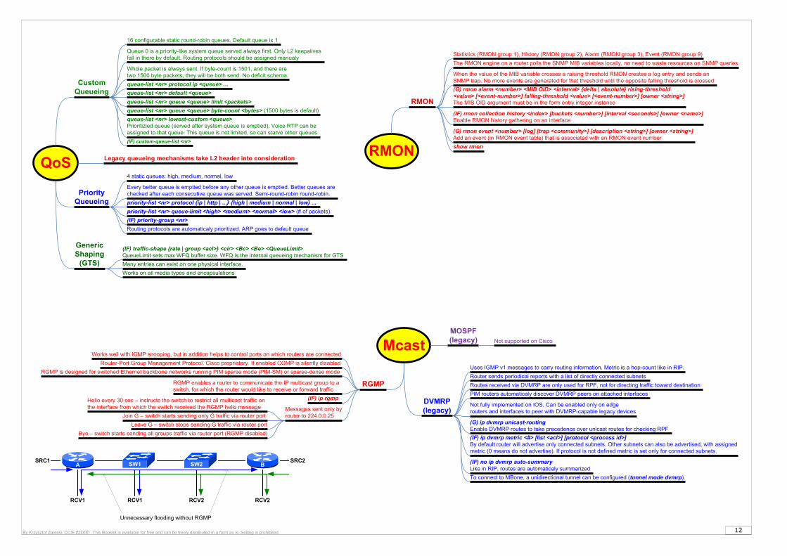
Mcast
DVMRP(legacy)
PIM routers automaticaly discover DVMRP peers on attached interfaces
Router sends periodical reports with a list of directly connected subnets
(G) ip dvmrp unicast-routingEnable DVMRP routes to take precedence over unicast routes for checking RPF
(IF) ip dvmrp metric <#> [list <acl>] [protocol <process id>]By default router will advertise only connected subnets. Other subnets can also be advertised, with assigned metric (0 means do not advertise). If protocol is not defined metric is set only for connected subnets.
Uses IGMP v1 messages to carry routing information. Metric is a hop-count like in RIP.
Routes received via DVMRP are only used for RPF, not for directing traffic toward destination
Not fully implemented on IOS. Can be enabled only on edge routers and interfaces to peer with DVMRP-capable legacy devices
(IF) no ip dvmrp auto-summaryLike in RIP, routes are automaticaly summarized
To connect to MBone, a unidirectional tunnel can be configured (tunnel mode dvmrp).
MOSPF(legacy) Not supported on Cisco
RGMP
Router-Port Group Management Protocol. Cisco proprietary. If enabled CGMP is silently disabled
Works well with IGMP snooping, but in addition helps to control ports on which routers are connected
RGMP enables a router to communicate the IP multicast group to a switch, for which the router would like to receive or forward traffic
Messages sent only by router to 224.0.0.25
Hello every 30 sec – instructs the switch to restrict all multicast traffic on the interface from which the switch received the RGMP hello message
Join G – switch starts sending only G traffic via router port
Bye – switch starts sending all groups traffic via router port (RGMP disabled)
(IF) ip rgmp
RGMP is designed for switched Ethernet backbone networks running PIM sparse mode (PIM-SM) or sparse-dense mode
BSW2SW1A
RCV1
SRC1 SRC2
RCV2RCV2RCV1
Unnecessary flooding without RGMP
Leave G – switch stops sending G traffic via router port
QoS
Custom Queueing
queue-list <nr> protocol ip <queue> ...
queue-list <nr> default <queue>
queue-list <nr> queue <queue> limit <packets>
queue-list <nr> queue <queue> byte-count <bytes> (1500 bytes is default)
16 configurable static round-robin queues. Default queue is 1
Queue 0 is a priority-like system queue served always first. Only L2 keepalives fall in there by default. Routing protocols should be assigned manualy
Whole packet is always sent. If byte-count is 1501, and there are two 1500 byte packets, they will be both send. No deficit schema.
(IF) custom-queue-list <nr>
queue-list <nr> lowest-custom <queue>Prioritizied queue (served after system queue is emptied). Voice RTP can be assigned to that queue. This queue is not limited, so can starve other queues
Priority Queueing priority-list <nr> protocol {ip | http | ...} {high | medium | normal | low} ...
priority-list <nr> queue-limit <high> <medium> <normal> <low> (# of packets)
(IF) priority-group <nr>
Every better queue is emptied before any other queue is emptied. Better queues are checked after each consecutive queue was served. Semi-round-robin round-robin.
4 static queues: high, medium, normal, low
Routing protocols are automaticaly prioritized. ARP goes to default queue
Legacy queueing mechanisms take L2 header into consideration
Generic Shaping
(GTS)
(IF) traffic-shape {rate | group <acl>} <cir> <Bc> <Be> <QueueLimit>QueueLimit sets max WFQ buffer size. WFQ is the internal queueing mechanism for GTS
Many entries can exist on one physical interface.
Works on all media types and encapsulations
RMON
RMON
The RMON engine on a router polls the SNMP MIB variables locally, no need to waste resources on SNMP queries
When the value of the MIB variable crosses a raising threshold RMON creates a log entry and sends an SNMP trap. No more events are generated for that threshold until the opposite falling threshold is crossed
(G) rmon alarm <number> <MIB OID> <interval> {delta | absolute} rising-threshold <value> [<event-number>] falling-threshold <value> [<event-number>] [owner <string>]The MIB OID argument must be in the form entry.integer.instance
(G) rmon event <number> [log] [trap <community>] [description <string>] [owner <string>]Add an event (in RMON event table) that is associated with an RMON event number
(IF) rmon collection history <index> [buckets <number>] [interval <seconds>] [owner <name>]Enable RMON history gathering on an interface
Statistics (RMON group 1), History (RMON group 2), Alarm (RMON group 3), Event (RMON group 9)
show rmon

13By Krzysztof Zaleski, CCIE #24081. This Booklet is available for free and can be freely distributed in a form as is. Selling is prohibited.
WCCP
Up to 32 Content Engines for a router in WCCPv1. CE with lowest IP is elected as leading Content Engine
In WCCPv2 (default) there can be more than one router serving Content Engine cluster
WCCPv1 supports only HTTP (port 80) traffic
WCCPv2 supports MD5 authentication and load distribution
(G) ip wccp web-cache group-address <multicast> password <pass>
(IF) ip wccp web-cache redirect out – select interface toward Internet)
(IF) ip wccp redirect exclude inExclude interface from redirecion (usualy interface where WCCP server is located – redirect out mode)
(G) ip wccp web-cache redirect-list <acl> - for which clients redirection is enabled
(G) ip wccp web-cache group-list <acl> - which cache engines are allowed to participate
Features
Config
(G) ip wccp web-cache (enable WCCP)
WCCP works only with IPv4 networks. Uses UDP/2048
When WCCP forwards traffic via GRE, the redirected packets are encapsulated within a GRE header, and a WCCP redirect header. When WCCP forwards traffic using L2 (Cache Engine is on the same segment as the router), the original MAC header of the IP packet is overwritten and replaced with the MAC header for the WCCP client.
(G) ip wccp mode {open | closed}When closed mode is enabled, and a content engine is not available, all traffic which would normaly be passed through it, is blocked
(IF) ip wccp web-cache redirect in – select interface toward local LAN
redirect in
ingress intf egress intf
WCCP-enabledServer
L2/GRE L2/GRE
redirect out
ingress intf egress intf
WCCP-enabledServer
L2/GRE L2/GRE
exclude in
WCCP redirect modes
show ip wccp
show wccp status
FlexLink
FlexLink
Flex Links are a pair of a Layer 2 interfaces where one interface is configured to act as a backup to the other. Users can disable STP and still retain basic link redundancy. It’s a sort of UplinkFast without STP
Both Flex Link ports are always part of multicast groups
The MAC address-table move update feature allows the switch to provide rapid bidirectional convergence when a primary link goes down and the standby link begins forwarding traffic
A backup link does not have to be the same type
STP is automaticaly disabled on Flex Link ports
(IF) switchport backup interface <intf>
(IF) switchport backup interface <intf> preemption mode [forced | bandwidth | off]forced – active always preempts; bandwidth - intf with higher BW always acts as active
(IF) switchport backup interface <intf> preemption delay <sec> (default 35 sec)
(IF) switchport backup interface <intf> mmu primary vlan <vlan-id>If not defined, the lowest VLAN is used for MAC-address move updates
(G) mac address-table move update transmitEnable the access switch to send MAC address-table move updates to other switches
(G) mac address-table move update receiveEnable the switch to get and process the MAC address-table move updates
VLAN Flex Link load-balancing allow both ports to forward the traffic for some mutually exclusive VLANs
(IF) switchport backup interface <if> multicast fast-convergenceLeak IGMP messages on backup link so upstream switch can be aware of alternate path
(IF) switchport backup interface <if> prefer vlan <vlan-range>
show interface switchport backup [detail]
QinQ
QinQTuneling
Use the vlan dot1q tag native global command to configure the edge switch, so that all packets going out IEEE 802.1q trunk, including the native VLAN, are tagged
(IF) switchport mode dot1q-tunnel
The native VLAN of the IEEE 802.1Q trunks must not match any native VLAN of the nontrunking (tunneling) port on the same switch
Supports CDP, STP, MSTP, VTP, PAgP, LACP, and UDLD (No DTP)
(IF) l2protocol-tunnel [cdp | stp | vtp]By default CDP, STP and VTP are not enabled on tunneled interfaces
(IF) l2protocol-tunnel cos <value>COS applied to all tunneled traffic. If not defined, default is COS 5. Inner COS is preserved
(IF) l2protocol-tunnel point-to-point [pagp | lacp | udld]Tunnel etherchannel frames. Each pair of remote ports must be in different access VLAN
Tagged frames (Ethertype 0x8100) encapsulated within additional 4 byte 802.1q header (EtherType 0x88a8), so system mtu 1504 must be added to all switches, otherwise some protocols may not work properly (OSPF)
(IF) switchport access vlan <id>Outer VLAN for tunneled traffic
(IF) l2protocol-tunnel shutdown-threshold [cdp | stp | vtp] <pps> (IF) l2protocol-tunnel drop-threshold [cdp | stp | vtp] <pps>(IF) l2protocol-tunnel shutdown-threshold [point-to-point [pagp | lacp | udld]] <pps> (IF) l2protocol-tunnel drop-threshold [point-to-point [pagp | lacp | udld]] <pps>
show l2protocol