Cisco Nexus 5000 FCoE/Enet Configuration Guideqgt.qlogic.com/Hidden/support/Current Answer...
15
Cisco Nexus 5000 FCoE/Enet Configuration Guide Modified - 8 April 2013 Page 1 Author: Sharon Kahn - Feb 2013 1 Device Overview ................................................................................................................................... 2 2 To Access the Switch ............................................................................................................................. 3 3 Navigating the User Interface ............................................................................................................... 3 4 Configure device as Layer 2 Ethernet switch (with VLANs) .................................................................. 4 5 Configure Device as FCoE Gateway ...................................................................................................... 6 6 Configure Priority Flow Control (PFC) ................................................................................................. 10 7 Layer 2 Link Aggregation Groups (LAG) .............................................................................................. 12 8 Shepard: VC-flexfabric in multi-pathed dual-hop configuration ........................................................ 13 9 Mercury - configure switch side of FCoE configuration ...................................................................... 15
-
Upload
nguyendang -
Category
Documents
-
view
246 -
download
2
Transcript of Cisco Nexus 5000 FCoE/Enet Configuration Guideqgt.qlogic.com/Hidden/support/Current Answer...

Cisco Nexus 5000 FCoE/Enet Configuration Guide
Modified - 8 April 2013 Page 1
Author: Sharon Kahn - Feb 2013
1 Device Overview ................................................................................................................................... 2
2 To Access the Switch ............................................................................................................................. 3
3 Navigating the User Interface ............................................................................................................... 3
4 Configure device as Layer 2 Ethernet switch (with VLANs) .................................................................. 4
5 Configure Device as FCoE Gateway ...................................................................................................... 6
6 Configure Priority Flow Control (PFC) ................................................................................................. 10
7 Layer 2 Link Aggregation Groups (LAG) .............................................................................................. 12
8 Shepard: VC-flexfabric in multi-pathed dual-hop configuration ........................................................ 13
9 Mercury - configure switch side of FCoE configuration ...................................................................... 15

Cisco Nexus 5000 FCoE/Enet Configuration Guide
Modified - 8 April 2013 Page 2
How to configure a Cisco Nexus 5xxx switch to function as an Ethernet switch or FCoE gateway in a
variety of testbeds.
1 Device Overview
1.1 Device Capabilities
The Cisco Nexus 5000 series switches can be configured as a Layer2 switch with full CEE/DCB capabilities .
Alternatively, the device can be configured as a full-featured FCoE gateway, providing both the FCF gateway and full Fibre Channel nameserver/domain management services. Note that the switch must be configured globally one way or the other: for FCoE or switching.
Note that this switch model does not have “flex-ports.” Ports (or “interfaces” as Cisco always calls them) are either Ethernet or Fibre Channel.
1.2 Usefulness in FCoE testbeds This switch can be used in two distinctly different ways in an FCoE testbed.
As a full-featured FCoE gateway. Ethernet server traffic comes in the Ethernet ports, where it logs in to an FCF. The Fibre Channel ports can be connected directly to storage devices or to a fabric.
As a Layer 2 switch configured to pass both untagged and tagged Ethernet packets (including FCoE frames) in one Ethernet port and out another.

Cisco Nexus 5000 FCoE/Enet Configuration Guide
Modified - 8 April 2013 Page 3
2 To Access the Switch Use Console cable to set up basic networking using Cisco IOS.
2.1 Default login info User: admin (cisco default)
Password: password (this is our usual password. Cisco does not provide a default password)
2.2 Networking configuration (IP address, gateway, etc.) Note that the mgmt port is handled within something called “vrf context management.” This is very
tricky to use. It’s best to just use the setup script, which can be used to modify existing network
configuration as well as for initial configuration. Just be careful about taking defaults - they may
overwrite your desired system settings with the default values!
IBM-Nexus5020# setup ---- Basic System Configuration Dialog ---- This setup utility will guide you through the basic configuration of the system. Setup configures only enough connectivity for management of the system. *Note: setup is mainly used for configuring the system initially, when no configuration is present. So setup always assumes system defaults and not the current system configuration values. Press Enter at anytime to skip a dialog. Use ctrl-c at anytime to skip the remaining dialogs. Would you like to enter the basic configuration dialog (yes/no):
3 Navigating the User Interface
3.1 Web GUI This device does not have a built-in http GUI. There is a separate product called Fabric Manager that
provides a GUI interface, but we have never installed it.
3.2 CLI Once the networking setup is complete, you can access the CLI via telnet or ssh.

Cisco Nexus 5000 FCoE/Enet Configuration Guide
Modified - 8 April 2013 Page 4
4 Configure device as Layer 2 Ethernet switch (with VLANs) In this example a subset of 3 Ethernet ports is clustered together to form a virtual Layer2 switch that will
pass packets tagged as VLAN 10 among all the ports in the group. These ports will also pass untagged
frames. Untagged frames will be assumed to be in the default vlan (1) unless a different “native vlan” is
configured on the trunk port.
4.1 Disable FCoE Gateway This is a switch-wide setting. If you are planning to use this switch for Ethernet switching, you have to
disable the FCoE Gateway capability!
IBM-Nexus5020# conf t IBM-Nexus5020(config)# no feature fcoe
4.2 Define port type and VLANs
4.2.1 Define all VLANs
IBM-Nexus5020# conf t IBM-Nexus5020(config)# vlan 10 IBM-Nexus5020(config-vlan)#
4.2.2 Assign desired set of ports to “trunk” specific VLAN
In this case, ports 29-31 function like a standalone Ethernet switch, passing all incoming packets tagged
as VLAN 10 among these 3 ports. Typical use: configure switch to pass FCoE frames from VLAN 10.
IBM-Nexus5020(config)# interface ethernet 1/29-31 IBM-Nexus5020(config-if-range)#switchport mode trunk IBM-Nexus5020(config-if-range)#switchport trunk allowed vlan 10
4.3 Verify switch setup
4.3.1 Verify mac-layer traffic on interfaces with “show mac address-table”
The following display shows the bridge forwarding tables. These tables are populated by passively
recording the source mac address of every packet that arrives on each interface.
# show mac address-table Legend: * - primary entry, G - Gateway MAC, (R) - Routed MAC, O - Overlay MAC age - seconds since last seen,+ - primary entry using vPC Peer-Link VLAN MAC Address Type age Secure NTFY Ports/SWID.SSID.LID ---------+-----------------+--------+---------+------+----+------------------ * 21 00c0.dd24.2016 dynamic 10 F F Eth1/9 * 21 00c0.dd24.2076 dynamic 10 F F Eth1/11 * 101 00c0.dd24.2058 dynamic 10 F F Eth1/1 * 101 a0b3.cc1d.87d9 dynamic 10 F F Eth1/3
Cisco Nexus 5000 FCoE/Enet Configuration Guide
Modified - 8 April 2013 Page 5
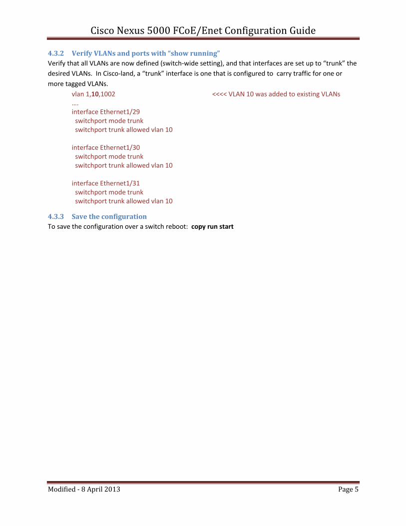
4.3.2 Verify VLANs and ports with “show running”
Verify that all VLANs are now defined (switch-wide setting), and that interfaces are set up to “trunk” the
desired VLANs. In Cisco-land, a “trunk” interface is one that is configured to carry traffic for one or
more tagged VLANs.
vlan 1,10,1002 <<<< VLAN 10 was added to existing VLANs …. interface Ethernet1/29 switchport mode trunk switchport trunk allowed vlan 10 interface Ethernet1/30 switchport mode trunk switchport trunk allowed vlan 10 interface Ethernet1/31 switchport mode trunk switchport trunk allowed vlan 10
4.3.3 Save the configuration
To save the configuration over a switch reboot: copy run start

Cisco Nexus 5000 FCoE/Enet Configuration Guide
Modified - 8 April 2013 Page 6
5 Configure Device as FCoE Gateway The example below sets up an FCoE switch for 2 Ethernet server ports and 2 Fibre Channel storage ports.
1) ethernet 1/4 and ethernet1/8 connected to CNA or Eth ports on our DUT 2) fibre channel ports fc3/4 and fc3/5 connected to storage or FC fabric 3) FCoE network uses vlanid 130.
Note: you must be in config mode to execute the following commands: “config t”
5.1 Enable FCoE Gateway This is a switch-wide setting. If you are planning to use this switch for FCoE, this feature must be
enabled globally. Note that once you do this you will no longer be able to use any of the ports on this
switch for plain Layer 2 forwarding. It’s all or nothing.
IBM-Nexus5020# conf t IBM-Nexus5020(config)# feature fcoe
5.2 create vsan “testing_lun” and add storage fc interfaces Assigning the name “testing_lun” is optional, for display purposes only.
vsan database vsan 130 vsan 130 name testing_lun vsan 130 interface fc3/4 vsan 130 interface fc3/5
5.3 config vlan and associate this vlan with vsan vlan 130 fcoe vsan 130
5.4 configure ethernet port with vlan interface ethernet 1/4 switchport mode trunk switchport access vlan 130 switchport trunk allowed vlan 130 priority-flow-control mode auto spanning-tree port type edge trunk interface ethernet 1/8 switchport mode trunk switchport access vlan 130 switchport trunk allowed vlan 130 priority-flow-control mode auto spanning-tree port type edge trunk

Cisco Nexus 5000 FCoE/Enet Configuration Guide
Modified - 8 April 2013 Page 7
5.5 Create Virtual FibreChannel Interface (vfc) and bind it to ethernet interface vfc 4 bind interface ethernet 1/4 no shutdown interface vfc 8 bind interface ethernet 1/8 no shutdown
5.6 Config vsan to use vfc vsan database vsan 130 interface vfc 4 vsan 130 interface vfc 8
5.7 Configure Zoning for vsan zone name SS2_DH_B3m1p vsan 130 member pwwn 10:00:D8:D3:85:D5:8C:51 <<<<<<<< CNA port member pwwn 10:00:D8:D3:85:D5:8C:55 <<<<<<<< CNA port member pwwn 21:83:00:02:AC:00:14:1E <<<<<<<< Storage ports member pwwn 21:83:00:02:AC:00:14:1E <<<<<<<< Storage ports exit
5.8 Configure and activate Zoneset zoneset name SS2_DH vsan 130 member SS2_DH_B3m1p exit zoneset activate name SS2_DH vsan 130

Cisco Nexus 5000 FCoE/Enet Configuration Guide
Modified - 8 April 2013 Page 8
5.9 Verify configuration with Cisco “show” commands
Excerpt from “show running”
vlan 130 fcoe vsan 130 vsan database vsan 130 name "dualHopLun" fcdomain fcid database vsan 1 wwn 21:83:00:02:ac:00:14:1e fcid 0xed000b dynamic vsan 130 wwn 21:83:00:02:ac:00:14:1e fcid 0x330000 dynamic vsan 130 wwn 10:00:d8:d3:85:d5:8c:55 fcid 0x330001 dynamic vsan 1 wwn 21:84:00:02:ac:00:14:1e fcid 0xed000c dynamic vsan 130 wwn 21:84:00:02:ac:00:14:1e fcid 0x330002 dynamic … interface vfc4 bind interface Ethernet1/4 no shutdown interface vfc8 bind interface Ethernet1/8 no shutdown vsan database vsan 130 interface vfc4 vsan 130 interface vfc8 vsan 130 interface fc3/4 vsan 130 interface fc3/5
show vsan membership
Cisco5020-Supershaw-229# show vsan 130 membership vsan 130 interfaces: fc3/4 fc3/5 vfc4 vfc8
show fcoe
Cisco5020-Supershaw-229# show fcoe Global FCF details FCF-MAC is 54:7f:ee:5f:1f:c0 FC-MAP is 0e:fc:00 FCF Priority is 128 FKA Advertisement period for FCF is 8 seconds VFC MAC details vfc4 FCF-MAC is 54:7f:ee:5f:1f:c0 vfc8 FCF-MAC is 54:7f:ee:5f:1f:c0

Cisco Nexus 5000 FCoE/Enet Configuration Guide
Modified - 8 April 2013 Page 9
show vlan fcoe
Cisco5020-Supershaw-229# show vlan fcoe Original VLAN ID Translated VSAN ID Association State --------------------- --------------------------- ---------------------- 130 130 Operational
show fcoe database
Cisco5020-Supershaw-229# show fcoe database ---------------------------------------------------------------------------------------------- INTERFACE FCID PORT NAME MAC ADDRESS ----------------------------------------------------------------------------------------------- vfc4 0x330001 10:00:d8:d3:85:d5:8c:55 d8:d3:85:d5:8c:55 vfc8 0x330003 10:00:d8:d3:85:d5:8c:51 d8:d3:85:d5:8c:51 Total number of flogi count from FCoE devices = 2.
show flogi database
Cisco5020-Supershaw-229# show flogi database -------------------------------------------------------------------------------- INTERFACE VSAN FCID PORT NAME NODE NAME -------------------------------------------------------------------------------- fc3/4 130 0x330002 21:84:00:02:ac:00:14:1e 2f:f7:00:02:ac:00:14:1e fc3/5 130 0x330000 21:83:00:02:ac:00:14:1e 2f:f7:00:02:ac:00:14:1e vfc4 130 0x330001 10:00:d8:d3:85:d5:8c:55 20:00:d8:d3:85:d5:8c:55 vfc8 130 0x330003 10:00:d8:d3:85:d5:8c:51 20:00:d8:d3:85:d5:8c:51 Total number of flogi = 4.
5.9.1 Save the configuration
To save the configuration over a switch reboot: copy run start

Cisco Nexus 5000 FCoE/Enet Configuration Guide
Modified - 8 April 2013 Page 10
6 Configure Priority Flow Control (PFC)
6.1 Background info from Cisco Nexus 50000 Series NX-OS Software Configuration Guide. See latest version online.
The priority flow control (PFC) capability allows you to apply pause functionality to specific classes of
traffic. PFC decides whether to apply pause based on the IEEE 802.1p CoS value (a 3-bit field in the
Ethernet tag field).
The FCoE system class has a default CoS value of 3. You can add a “match cos” configuration to the
FCoE system class to set a different CoS value. PFC Pause will be applied to all traffic that matches the
new value(s).
Relevant definitions
• Drop : “no drop” specifies lossless service for the system class. Drop specifies that tail drop is used
when a queue for this system class is full.
• Match CoS value : specifies the IEEE 802.1p CoS value to associate with this system class.
Default system classes:
• FCoE system class
All Fibre Channel and FCoE control and data traffic is automatically classified into the FCoE system
class, which provides no-drop service. This class is created automatically when the system starts
up (the class is named class-fcoe in the CLI). You cannot delete this class, and you can only
modify the IEEE 802.1p CoS value to associate with this class.
The switch classifies packets into the FCoE system class as follows:
– FCoE traffic is classified based on EtherType.
– Native Fibre Channel traffic is classified based on the physical interface type.
• Drop system class - details not relevant here
6.2 PFC commands Note : The policy maps discussed here are global policy-maps, not interface specific. The switch
distributes all the policy map configuration values to the attached network adapters.
enable PFC (usually enabled by default) - this setting is per interface
switch# interface <interface-name> switch(config-if)# priority-flow-control mode
create a class map
switch# class-map <name> ## new or existing class switch(config)# match cos <cos-values> ## up to 4 values, separated by spaces
create a no-drop (lossless) policy-map and associate it with a class map
switch(config)# policy-map name

Cisco Nexus 5000 FCoE/Enet Configuration Guide
Modified - 8 April 2013 Page 11
switch(config-pmap)# class <class-name > pause no-drop
Verify your settings
show policy map show interface priority-flow-control
6.3 Example - modify class-fcoe to match 4 CoS settings When switch is configured as an FCoE device, there is a default class created for implementing “lossless
Ethernet” with COS 3 (the priority used by all FCoE traffic). Normally there is no reason to ever mess with
this configuration. However, Development occasionally wants to experiment with the PFC behavior and
may ask you to change the setting. If you do this, be sure to change it back when you are done!!
Display default configuration of the class-fcoe class. Cisco5010-8G-Mercury-221# show class-map class-fcoe Type qos class-maps =================== class-map type qos match-any class-fcoe match cos 3
Modify the class-fcoe class to pattern-match on a different COS (priority) switch# conf t switch(config)# class-map class-fcoe switch(config-cmap)# no match 3 switch(config-cmap)# match cos 1
Display new configuration of the class-fcoe class. Cisco5010-8G-Mercury-221# show class-map class-fcoe Type qos class-maps =================== class-map type qos match-any class-fcoe match cos 1
6.4 Example - modify CoS value of class-fcoe and create new no-drop class This example is from the Cisco Nexus 50000 Series NX-OS Software Configuration Guide.
In the following example, a new Ethernet no-drop system class is created, and the CoS values of
the default system classes are changed from their default values:
switch(config)# class-map trading-data-no-drop
switch(config-cmap)# match cos 5
switch(config)# class-map class-fcoe
switch(config-cmap)# match cos 2
switch(config)# policy-map system-policy
switch(config-pmap)# class trading-data-no-drop
switch(config-pmap-c)# pause no-drop
switch(config-pmap-c)# mtu 2000
switch(config)# system qos
switch(config-system)# service-policy system-policy

Cisco Nexus 5000 FCoE/Enet Configuration Guide
Modified - 8 April 2013 Page 12
In this example, the first class-map command defines a new Ethernet system class. Packets from
all over the system with 802.1p CoS value of 5 will be classified into this new system class.
The second class-map command changes the match value of the default no-drop system class.
The policy-map command defines a QoS policy for each traffic class. The new Ethernet class is
configured as a no-drop class, with an MTU of 2000 bytes. The pause no-drop command causes
PFC to apply pause functionality for packets with IEEE 802.1p priority value 5.
The service-policy command sets the specified policy as the system class.
7 Layer 2 Link Aggregation Groups (LAG)
There are many different terms for link aggregation: link bundling, NIC teaming, port channeling, port
trunking, Ethernet/network/NIC bonding. All of these terms are ways of saying that multiple physical
Ethernet links can be grouped together and made to act like a single physical cable.
Cisco uses the term “Port Channels” and also “LACP” (which is actually a standard protocol used to
negotiate Link Aggregation).
7.1 Overview A port channel bundles up to eight individual interfaces into a group to provide increased bandwidth and redundancy. Port channeling also load balances traffic across these physical interfaces. The port channel stays operational as long as at least one physical interface within the port channel is operational.
You create a port channel by bundling compatible interfaces. You can configure and run either static port channels or ports channels running the Link Aggregation Control Protocol (LACP)
7.2 Configuring static port channels (aka static LAG) A port channel bundles individual links into a channel group to create a single logical link that provides the aggregate bandwidth of up to eight physical links. If a member port within a port channel fails, traffic previously carried over the failed link switches to the remaining member ports within the port channel.
You can only add interfaces configured with the channel mode set to on to static port channels.
7.2.1 Create a new port-channel, then add interfaces to it
conf t interface port-channel <channel-group-number> ### range is 1-4096 interface ethernet <n/m> ### go into interface config channel-group <channel-group-number> ### add intf to channel-group
7.2.2 Verify with show commands
show interface port-channel … show port-channel database show port-channel summary
Cisco Nexus 5000 FCoE/Enet Configuration Guide
Modified - 8 April 2013 Page 13
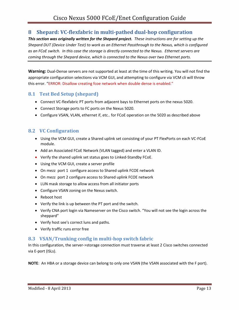
8 Shepard: VC-flexfabric in multi-pathed dual-hop configuration This section was originally written for the Shepard project. These instructions are for setting up the
Shepard DUT (Device Under Test) to work as an Ethernet Passthrough to the Nexus, which is configured
as an FCoE switch. In this case the storage is directly connected to the Nexus. Ethernet servers are
coming through the Shepard device, which is connected to the Nexus over two Ethernet ports.
Warning: Dual-Dense servers are not supported at least at the time of this writing. You will not find the
appropriate configuration selections via VCM GUI, and attempting to configure via VCM cli will throw
this error. “ERROR: Disallow creating fcoe network when double dense is enabled.”
8.1 Test Bed Setup (shepard)
Connect VC-flexfabric PT ports from adjacent bays to Ethernet ports on the nexus 5020.
Connect Storage ports to FC ports on the Nexus 5020.
Configure VSAN, VLAN, ethernet if, etc.. for FCoE operation on the 5020 as described above
8.2 VC Configuration
Using the VCM GUI, create a Shared uplink set consisting of your PT FlexPorts on each VC-FCoE module.
Add an Associated FCoE Network (VLAN tagged) and enter a VLAN ID.
Verify the shared uplink set status goes to Linked-Standby FCoE.
Using the VCM GUI, create a server profile
On mezz port 1 configure access to Shared uplink FCOE network
On mezz port 2 configure access to Shared uplink FCOE network
LUN mask storage to allow access from all initiator ports
Configure VSAN zoning on the Nexus switch.
Reboot host
Verify the link is up between the PT port and the switch.
Verify CNA port login via Nameserver on the Cisco switch. “You will not see the login across the sheppard”
Verify host see's correct luns and paths.
Verify traffic runs error free
8.3 VSAN/Trunking config in multi-hop switch fabric In this configuration, the server->storage connection must traverse at least 2 Cisco switches connected
via E-port (ISLs).
NOTE: An HBA or a storage device can belong to only one VSAN (the VSAN associated with the F port).
Cisco Nexus 5000 FCoE/Enet Configuration Guide
Modified - 8 April 2013 Page 14
8.3.1 Verify settings match on Cisco switches
Check all Cisco switches on the same interoperability mode: default (#> show vsan)
Check all Trunk Eport mode Enabled ( #> show int br)
8.3.2 Add Eport’s to VSAN list on each end of ISL’s.
vsan database vsan 130 vsan 130 interface fc#/#
8.3.3 Verify you have all the switches you want connected in your VSAN.
show fcdomain domain-list
8.3.4 Add storage ports to VSAN on appropriate switches and ports.
vsan database vsan 130 vsan 130 interface fc#/#
8.3.5 Configure Zoning to include all host and storage ports for the vsan
Distribute the VSAN zoning
zoneset distribute full vsan 130
8.4 VC Configuration for Ethernet and FCoE same CNA port. Configuring Ethernet and FCoE on the same port just requires assigning another vlan to the port, one for
Ethernet, one for FCoE.
VC Ethernet and FCoE out same physical CNA port and same uplink port.
Add Ethernet VLAN to FCoE shared uplink set.
Add Ethernet connection to server profile.

Cisco Nexus 5000 FCoE/Enet Configuration Guide
Modified - 8 April 2013 Page 15
9 Mercury - configure switch side of FCoE configuration The Mercury project is a standalone FCoE switching device that includes full implementations of both
Fibre Channel nameserver/domain manager and the FCoE FCF (Fibre Channel Forwarder). However,
Mercury does not include a full-featured Layer 2 CEE/DCB Ethernet stack. This means that for FCoE
testing, a standalone Layer 2 CEE/DCB switch is required between the CNA servers and the Mercury
device. Mercury also supports Ethernet pass-through ports, which can be connected to an external
Ethernet switch with FCF capabilities. The Nexus 5000 can be configured for either of these two roles
(as described in the preceding sections).
This section describes how the Mercury must be configured to interact with the Nexus in each scenario.
9.1 Mercury setup to work with Nexus as L2 Ethernet switch TBD
9.2 Mercury setup to work with Nexus as FCoE gateway (FCF and FC switch) TBD