Cisco Nexus 3000 Series NX-OS VXLAN Configuration Guide ... · Cisco Nexus 3000 Series NX-OS VXLAN...
130
Cisco Nexus 3000 Series NX-OS VXLAN Configuration Guide, Release 9.2(x) First Published: 2018-07-18 Last Modified: 2019-07-24 Americas Headquarters Cisco Systems, Inc. 170 West Tasman Drive San Jose, CA 95134-1706 USA http://www.cisco.com Tel: 408 526-4000 800 553-NETS (6387) Fax: 408 527-0883
Transcript of Cisco Nexus 3000 Series NX-OS VXLAN Configuration Guide ... · Cisco Nexus 3000 Series NX-OS VXLAN...

Cisco Nexus 3000 Series NX-OS VXLAN Configuration Guide, Release9.2(x)First Published: 2018-07-18
Last Modified: 2019-07-24
Americas HeadquartersCisco Systems, Inc.170 West Tasman DriveSan Jose, CA 95134-1706USAhttp://www.cisco.comTel: 408 526-4000
800 553-NETS (6387)Fax: 408 527-0883

© 2018 Cisco Systems, Inc. All rights reserved.
C O N T E N T S
Preface viiP R E F A C E
Audience vii
Document Conventions vii
Related Documentation for Cisco Nexus 3000 Series Switches viii
Documentation Feedback viii
Communications, Services, and Additional Information viii
New and Changed Information 1C H A P T E R 1
New and Changed Information in this Release 1
Configuring VXLANs 3C H A P T E R 2
Overview 3
VXLAN Overview 3
VXLAN Encapsulation and Packet Format 4
VXLAN Tunnel Endpoints 4
VXLAN Packet Forwarding Flow 5
VXLAN Implementation on Cisco Nexus 3100 Series Switches 5
Layer 2 Mechanisms for Broadcast, Unknown Unicast, and Multicast Traffic 5
Layer 2 Mechanisms for Unicast-Learned Traffic 5
VXLAN Layer 2 Gateway as a Transit Multicast Router 6
ECMP and LACP Load Sharing with VXLANs 6
Guidelines and Limitations for VXLANs 6
Verified Scale Numbers on Cisco Nexus C3132Q-V, C31108PC-V, and C31108TC-V SeriesSwitches 8
FHRP Over VXLAN 9
Overview of FHRP over VXLAN 9
Cisco Nexus 3000 Series NX-OS VXLAN Configuration Guide, Release 9.2(x)iii

Guidelines and Limitations for FHRP Over VXLAN 10
FHRP Over VXLAN Topology 10
Considerations for VXLAN Deployment 12
vPC Guidelines and Limitations for VXLAN Deployment 12
Configuring VXLAN Traffic Forwarding 14
Enabling and Configuring the PIM Feature 14
Configuring a Rendezvous Point 15
Enabling a VXLAN 16
Mapping a VLAN to a VXLAN VNI 17
Configuring a Routing Protocol for NVE Unicast Addresses 17
Creating a VXLAN Destination UDP Port 18
Creating and Configuring an NVE Interface 19
Configuring Replication for a VNI 19
Configuring Multicast Replication 20
Configuring Ingress Replication 20
Configuring Q-in-VNI 21
Verifying the VXLAN Configuration 22
IGMP Snooping Over VXLAN 25C H A P T E R 3
Overview of IGMP Snooping Over VXLAN 25
Guidelines and Limitations for IGMP Snooping Over VXLAN 25
Configuring IGMP Snooping Over VXLAN 26
Configuring VXLAN BGP EVPN 27C H A P T E R 4
Information About VXLAN BGP EVPN 27
Guidelines and Limitations for VXLAN BGP EVPN 27
Notes for EVPN Convergence 29
Considerations for VXLAN BGP EVPN Deployment 29
VPC Considerations for VXLAN BGP EVPN Deployment 30
Network Considerations for VXLAN Deployments 32
Considerations for the Transport Network 33
BGP EVPN Considerations for VXLAN Deployment 34
Configuring VXLAN BGP EVPN 35
Enabling VXLAN 35
Cisco Nexus 3000 Series NX-OS VXLAN Configuration Guide, Release 9.2(x)iv
Contents

Configuring VLAN and VXLAN VNI 36
Configuring VRF for VXLAN Routing 36
Configuring SVI for Hosts for VXLAN Routing 37
Configuring VRF Overlay VLAN for VXLAN Routing 37
Configuring VNI Under VRF for VXLAN Routing 37
Configuring Anycast Gateway for VXLAN Routing 38
Configuring the NVE Interface and VNIs 38
Configuring BGP on the VTEP 38
Configuring RD and Route Targets for VXLAN Bridging 39
Configuring BGP for EVPN on the Spine 40
Suppressing ARP 41
Disabling VXLANs 42
Duplicate Detection for IP and MAC Addresses 42
Enabling Nuage Controller Interoperability 44
Verifying the VXLAN BGP EVPN Configuration 45
Example of VXLAN BGP EVPN (EBGP) 46
Example of VXLAN BGP EVPN (IBGP) 57
Example Show Commands 68
VXLAN Cross Connect 70
About VXLAN Cross Connect 70
Guidelines and Limitations for VXLAN Cross Connect 71
Configuring VXLAN Cross Connect 72
Verifying VXLAN Cross Connect Configuration 73
Configuring VXLAN OAM 75C H A P T E R 5
VXLAN OAM Overview 75
Loopback (Ping) Message 76
Traceroute or Pathtrace Message 77
Configuring VXLAN OAM 79
Configuring NGOAM Profile 82
NGOAM Authentication 83
Configuring VXLAN Multihoming 85C H A P T E R 6
VXLAN EVPN Multihoming Overview 85
Cisco Nexus 3000 Series NX-OS VXLAN Configuration Guide, Release 9.2(x)v
Contents

Introduction to Multihoming 85
BGP EVPN Multihoming Terminology 85
EVPN Multihoming Implementation 86
EVPN Multihoming Redundancy Group 87
Ethernet Segment Identifier 87
LACP Bundling 87
Guidelines and Limitations for VXLAN EVPN Multihoming 88
Configuring VXLAN EVPN Multihoming 88
Enabling EVPN Multihoming 88
VXLAN EVPN Multihoming Configuration Examples 89
Configuring Layer 2 Gateway STP 91
Layer 2 Gateway STP Overview 91
Guidelines for Moving to Layer 2 Gateway STP 91
Enabling Layer 2 Gateway STP on a Switch 92
Configuring VXLAN EVPN Multihoming Traffic Flows 95
EVPN Multihoming Local Traffic Flows 95
EVPN Multihoming Remote Traffic Flows 99
EVPN Multihoming BUM Flows 104
Configuring VLAN Consistency Checking 107
Overview of VLAN Consistency Checking 107
VLAN Consistency Checking Guidelines and Limitations 108
Displaying Show command Output for VLAN Consistency Checking 108
Configuring ESI ARP Suppression 109
Overview of ESI ARP Suppression 109
Limitations for ESI ARP Suppression 110
Configuring ESI ARP Suppression 110
Displaying Show Commands for ESI ARP Suppression 110
Configuring IPv6 Across a VXLAN EVPN Fabric 113C H A P T E R 7
Overview of IPv6 Across a VXLAN EVPN Fabric 113
Configuring IPv6 Across a VXLAN EVPN Fabric Example 113
Show Command Examples 117
Cisco Nexus 3000 Series NX-OS VXLAN Configuration Guide, Release 9.2(x)vi
Contents
Preface
This preface includes the following sections:
• Audience, on page vii• Document Conventions, on page vii• Related Documentation for Cisco Nexus 3000 Series Switches, on page viii• Documentation Feedback, on page viii• Communications, Services, and Additional Information, on page viii
AudienceThis publication is for network administrators who install, configure, and maintain Cisco Nexus switches.
Document ConventionsCommand descriptions use the following conventions:
DescriptionConventionBold text indicates the commands and keywords that you enter literallyas shown.
bold
Italic text indicates arguments for which the user supplies the values.Italic
Square brackets enclose an optional element (keyword or argument).[x]
Square brackets enclosing keywords or arguments separated by a verticalbar indicate an optional choice.
[x | y]
Braces enclosing keywords or arguments separated by a vertical barindicate a required choice.
{x | y}
Nested set of square brackets or braces indicate optional or requiredchoices within optional or required elements. Braces and a vertical barwithin square brackets indicate a required choice within an optionalelement.
[x {y | z}]
Cisco Nexus 3000 Series NX-OS VXLAN Configuration Guide, Release 9.2(x)vii
DescriptionConvention
Indicates a variable for which you supply values, in context where italicscannot be used.
variable
A nonquoted set of characters. Do not use quotation marks around thestring or the string will include the quotation marks.
string
Examples use the following conventions:
DescriptionConventionTerminal sessions and information the switch displays are in screen font.screen font
Information you must enter is in boldface screen font.boldface screen font
Arguments for which you supply values are in italic screen font.italic screen font
Nonprinting characters, such as passwords, are in angle brackets.< >
Default responses to system prompts are in square brackets.[ ]
An exclamation point (!) or a pound sign (#) at the beginning of a lineof code indicates a comment line.
!, #
Related Documentation for Cisco Nexus 3000 Series SwitchesThe entire Cisco Nexus 3000 Series switch documentation set is available at the following URL:
https://www.cisco.com/c/en/us/support/switches/nexus-3000-series-switches/tsd-products-support-series-home.html
Documentation FeedbackTo provide technical feedback on this document, or to report an error or omission, please send your commentsto [email protected]. We appreciate your feedback.
Communications, Services, and Additional Information• To receive timely, relevant information from Cisco, sign up at Cisco Profile Manager.
• To get the business impact you’re looking for with the technologies that matter, visit Cisco Services.
• To submit a service request, visit Cisco Support.
• To discover and browse secure, validated enterprise-class apps, products, solutions and services, visitCisco Marketplace.
• To obtain general networking, training, and certification titles, visit Cisco Press.
• To find warranty information for a specific product or product family, access Cisco Warranty Finder.
Cisco Nexus 3000 Series NX-OS VXLAN Configuration Guide, Release 9.2(x)viii
PrefaceRelated Documentation for Cisco Nexus 3000 Series Switches

Cisco Bug Search Tool
Cisco Bug Search Tool (BST) is a web-based tool that acts as a gateway to the Cisco bug tracking systemthat maintains a comprehensive list of defects and vulnerabilities in Cisco products and software. BST providesyou with detailed defect information about your products and software.
Cisco Nexus 3000 Series NX-OS VXLAN Configuration Guide, Release 9.2(x)ix
PrefacePreface

Cisco Nexus 3000 Series NX-OS VXLAN Configuration Guide, Release 9.2(x)x
PrefacePreface

C H A P T E R 1New and Changed Information
•
• New and Changed Information in this Release, on page 1
New and Changed Information in this ReleaseThe following table provides an overview of the significant changes made to this configuration guide. Thetable does not provide an exhaustive list of all the changes made to this guide or all new features in a particularrelease.
Where DocumentedAdded or Changed inRelease
DescriptionFeature
Title pageChanged the documenttitle from 9.x to 9.2(x)
Example ofVXLANBGPEVPN (EBGP), on page46
Example ofVXLANBGPEVPN (IBGP), on page57
9.2(1)Support added for thereduction of CLIcommands.
CLI Simplification
About VXLAN CrossConnect, on page 70
9.2(1)Provides point-to-pointtunneling of data andcontrol packets from oneVTEP to another.
VXLAN Cross Connect
Cisco Nexus 3000 Series NX-OS VXLAN Configuration Guide, Release 9.2(x)1

Cisco Nexus 3000 Series NX-OS VXLAN Configuration Guide, Release 9.2(x)2
New and Changed InformationNew and Changed Information in this Release

C H A P T E R 2Configuring VXLANs
•
• Overview, on page 3• Configuring VXLAN Traffic Forwarding, on page 14• Verifying the VXLAN Configuration, on page 22
Overview
VXLAN OverviewThe Cisco Nexus 3100 Series switches are designed for a hardware-based Virtual Extensible LAN (VXLAN)function. These switches can extend Layer 2 connectivity across the Layer 3 boundary and integrate betweenVXLAN and non-VXLAN infrastructures. Virtualized and multitenant data center designs can be shared overa common physical infrastructure.
VXLANs enable you to extend Layer 2 networks across the Layer 3 infrastructure by using MAC-in-UDPencapsulation and tunneling. In addition, you can use a VXLAN to build amultitenant data center by decouplingtenant Layer 2 segments from the shared transport network.
When deployed as a VXLANgateway, the CiscoNexus 3100 Series switches can connect VXLAN and classicVLAN segments to create a common forwarding domain so that tenant devices can reside in both environments.
A VXLAN has the following benefits:
• Flexible placement of multitenant segments throughout the data center.
It extends Layer 2 segments over the underlying shared network infrastructure so that tenant workloadscan be placed across physical pods in the data center.
• Higher scalability to address more Layer 2 segments.
A VXLAN uses a 24-bit segment ID called the VXLAN network identifier (VNID). The VNID allowsamaximum of 16million VXLAN segments to coexist in the same administrative domain. (In comparison,traditional VLANs use a 12-bit segment ID that can support a maximum of 4096 VLANs.)
• Utilization of available network paths in the underlying infrastructure.
VXLAN packets are transferred through the underlying network based on its Layer 3 header. It usesequal-cost multipath (ECMP) routing and link aggregation protocols to use all available paths.
Cisco Nexus 3000 Series NX-OS VXLAN Configuration Guide, Release 9.2(x)3
VXLAN Encapsulation and Packet FormatAVXLAN is a Layer 2 overlay scheme over a Layer 3 network. It usesMAC-in-UDP encapsulation to extendLayer 2 segments across the data center network. The transport protocol over the physical data center networkis IP plus UDP.
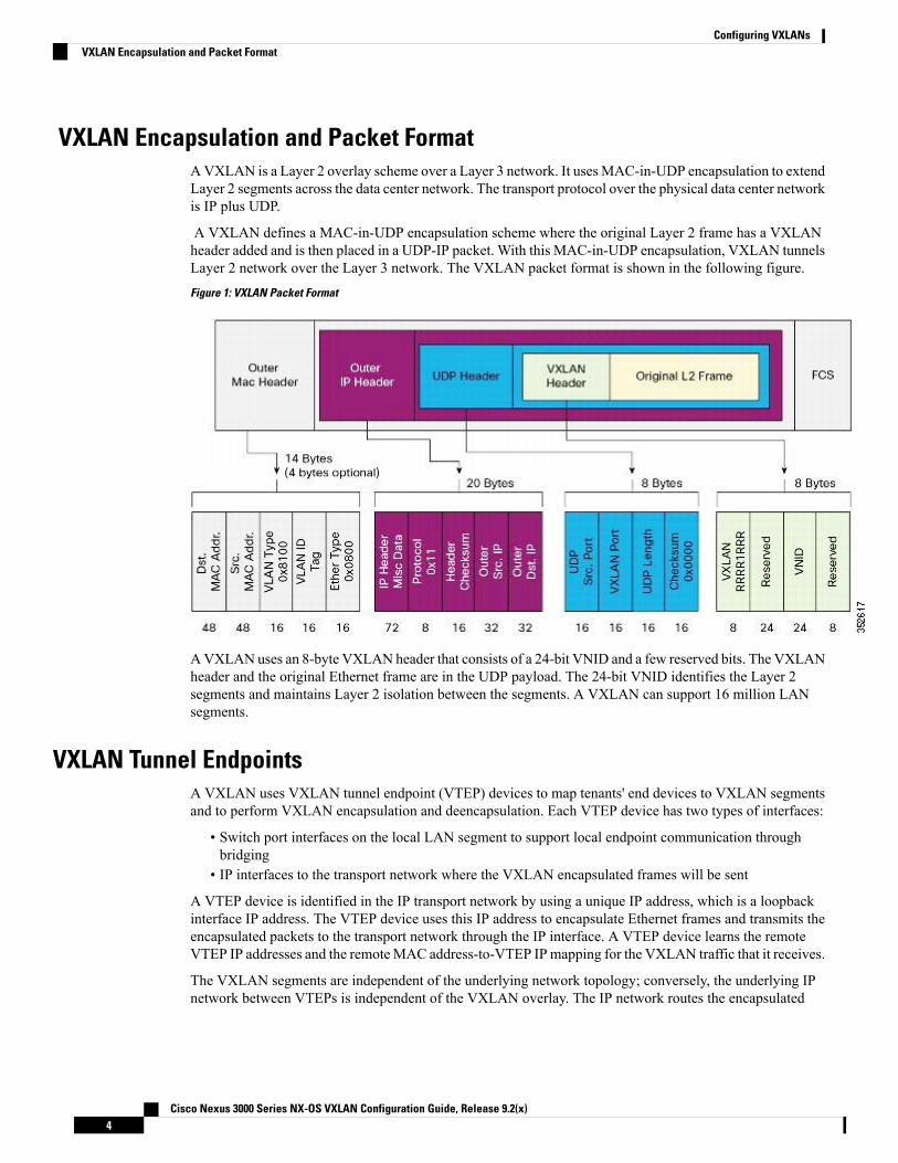
A VXLAN defines a MAC-in-UDP encapsulation scheme where the original Layer 2 frame has a VXLANheader added and is then placed in a UDP-IP packet. With this MAC-in-UDP encapsulation, VXLAN tunnelsLayer 2 network over the Layer 3 network. The VXLAN packet format is shown in the following figure.
Figure 1: VXLAN Packet Format
AVXLAN uses an 8-byte VXLAN header that consists of a 24-bit VNID and a few reserved bits. The VXLANheader and the original Ethernet frame are in the UDP payload. The 24-bit VNID identifies the Layer 2segments and maintains Layer 2 isolation between the segments. A VXLAN can support 16 million LANsegments.
VXLAN Tunnel EndpointsA VXLAN uses VXLAN tunnel endpoint (VTEP) devices to map tenants' end devices to VXLAN segmentsand to perform VXLAN encapsulation and deencapsulation. Each VTEP device has two types of interfaces:
• Switch port interfaces on the local LAN segment to support local endpoint communication throughbridging
• IP interfaces to the transport network where the VXLAN encapsulated frames will be sent
A VTEP device is identified in the IP transport network by using a unique IP address, which is a loopbackinterface IP address. The VTEP device uses this IP address to encapsulate Ethernet frames and transmits theencapsulated packets to the transport network through the IP interface. A VTEP device learns the remoteVTEP IP addresses and the remoteMAC address-to-VTEP IPmapping for the VXLAN traffic that it receives.
The VXLAN segments are independent of the underlying network topology; conversely, the underlying IPnetwork between VTEPs is independent of the VXLAN overlay. The IP network routes the encapsulated
Cisco Nexus 3000 Series NX-OS VXLAN Configuration Guide, Release 9.2(x)4
Configuring VXLANsVXLAN Encapsulation and Packet Format

packets based on the outer IP address header, which has the initiating VTEP as the source IP address and theterminating VTEP or multicast group IP address as the destination IP address.
VXLAN Packet Forwarding FlowA VXLAN uses stateless tunnels between VTEPs to transmit traffic of the overlay Layer 2 network throughthe Layer 3 transport network.
VXLAN Implementation on Cisco Nexus 3100 Series SwitchesThe Cisco Nexus 3100 Series switches support the hardware-based VXLAN function that extends Layer 2connectivity across the Layer 3 transport network and provides a high-performance gateway between VXLANand non-VXLAN infrastructures.
Layer 2 Mechanisms for Broadcast, Unknown Unicast, and Multicast TrafficA VXLAN on the Cisco Nexus 3100 Series switches uses flooding and dynamic MAC address learning todo the following:
• Transport broadcast, unknown unicast, and multicast traffic• Discover remote VTEPs• Learn remote host MAC addresses and MAC-to-VTEP mappings for each VXLAN segment
A VXLAN can forward these traffic types as follows:
• Using multicast in the core—IP multicast reduces the flooding of the set of hosts that are participatingin the VXLAN segment. Each VXLAN segment, or VNID, is mapped to an IP multicast group in thetransport IP network. The Layer 2 gateway uses Protocol IndependentMulticast (PIM) to send and receivetraffic from the rendezvous point (RP) for the IP multicast group. The multicast distribution tree for thisgroup is built through the transport network based on the locations of participating VTEPs.
• Using ingress replication—Each VXLAN segment or VXLAN network identifier (VNI) is mapped to aremote unicast peer. The Layer 2 frame is VXLAN encapsulated with the destination IP address as theremote unicast peer IP address and is sent out to the IP transport network where it gets unicast routed orforwarded to the remote destination.
Layer 2 Mechanisms for Unicast-Learned TrafficThe Cisco Nexus 3100 Series switches perform MAC address lookup-based forwarding for VXLANunicast-learned traffic.
When Layer 2 traffic is received on the access side, a MAC address lookup is performed for the destinationMAC address in the frame. If the lookup is successful, VXLAN forwarding is done based on the informationretrieved as a result of the lookup. The lookup result provides the IP address of the remote VTEP from whichthis MAC address is learned. This Layer 2 frame is then UDP/IP encapsulated with the destination IP addressas the remote VTEP IP address and is forwarded out of the appropriate network interface. In the Layer 3 cloud,this IP packet is forwarded to the remote VTEP through the route to that IP address in the network.
For unicast-learned traffic, you must ensure the following:
• The route to the remote peer is known through a routing protocol or through static routes in the network.• Adjacency is resolved.
Cisco Nexus 3000 Series NX-OS VXLAN Configuration Guide, Release 9.2(x)5
Configuring VXLANsVXLAN Packet Forwarding Flow

VXLAN Layer 2 Gateway as a Transit Multicast RouterA VXLAN Layer 2 gateway must terminate VXLAN-multicast traffic that is headed to any of the groups towhich VNIs are mapped. In a network, a VXLAN Layer 2 gateway can be a multicast transit router for thedownstream multicast receivers that are interested in the group's traffic. A VXLAN Layer 2 gateway must dosome additional processing to ensure that VXLAN multicast traffic that is received is both terminated andmulticast routed. This traffic processing is done in two passes:
1. The VXLANmulticast traffic is multicast routed to all network receivers interested in that group's traffic.
2. The VXLANmulticast traffic is terminated, decapsulated, and forwarded to all VXLAN access side ports.
ECMP and LACP Load Sharing with VXLANsEncapsulated VXLAN packets are forwarded between VTEPs based on the native forwarding decisions ofthe transport network. Most data center transport networks are designed and deployed with multiple redundantpaths that take advantage of various multipath load-sharing technologies to distribute traffic loads on allavailable paths.
A typical VXLAN transport network is an IP-routing network that uses the standard IP equal cost multipath(ECMP) to balance the traffic load among multiple best paths. To avoid out-of-sequence packet forwarding,flow-based ECMP is commonly deployed. An ECMP flow is defined by the source and destination IP addressesand optionally, the source and destination TCP or UDP ports in the IP packet header.
All the VXLAN packet flows between a pair of VTEPs have the same outer source and destination IP addresses,and all VTEP devices must use one identical destination UDP port that can be either the Internet AllocatedNumbers Authority (IANA)-allocated UDP port 4789 or a customer-configured port. The only variable elementin the ECMP flow definition that can differentiate VXLAN flows from the transport network standpoint isthe source UDP port. A similar situation for Link Aggregation Control Protocol (LACP) hashing occurs ifthe resolved egress interface that is based on the routing and ECMP decision is an LACP port channel. LACPuses the VXLAN outer-packet header for link load-share hashing, which results in the source UDP port beingthe only element that can uniquely identify a VXLAN flow.
In the Cisco Nexus 3100 Series switches implementation of VXLANs, a hash of the inner frame's header isused as the VXLAN source UDP port. As a result, a VXLAN flow can be unique. The IP address and UDPport combination is in its outer header while the packet traverses the underlay transport network.
Guidelines and Limitations for VXLANsVXLAN has the following guidelines and limitations:
• The configuration of the multicast groups and Ingress Replication (IR) is not supported at the same time.You can configure and deploy either multicast groups or IR to deploy VXLAN.
• The system vlan nve-overlayCLI is not required in Cisco Nexus 3000 Series switches with certain typesof BroadCom ASICs. Therefore, do not enable the system vlan nve-overlay CLI command.
• In VXLAN on vPC configuration, the packets fromNorth VTEP are decapped on the primary vPC switchand they are sent to all ports in the VLAN/VN-segment and they are also forwarded on the multicast linkto the secondary vPC switch. Therefore, the NVE VNI counters are observed to increment for both Txand Rx on the primary vPC switch, whereas the NVEVNI counters increment only for Rx on the secondaryvPC switch.
Cisco Nexus 3000 Series NX-OS VXLAN Configuration Guide, Release 9.2(x)6
Configuring VXLANsVXLAN Layer 2 Gateway as a Transit Multicast Router

• It is recommended that the summation of the number of the multicast groups and the OIFLs to be usedin a scaled environment should not exclude 1024 which is the current range of the multicast VXLANVP.
• Adjacencies are configured in different regions on an overlay or underlay network for different types ofL3 interfaces based on whether or not the VxLAN, VNI or VFI are enabled on the interface. MAC rewritedoes not happen if packets sent from a VFI enabled VLAN and hit an adjacency in an underlay network.So routing between VxLAN enabled VLANs and non-VxLAN enabled VLANs or L3 interfaces mayfail.
• IGMP snooping is supported on VXLAN VLANs.
• VXLAN routing is not supported. The default Layer 3 gateway for VXLANVLANsmust be provisionedon a different device.
VXLAN routing is supported for the following three new Cisco Nexus 3000Series platforms:
Note
• C3132Q-V
• C31108TC-V
• C31108PC-V
• Ensure that the network can accommodate an additional 50 bytes for the VXLAN header.
• Only one Network Virtualization Edge (NVE) interface is supported on a switch.
• Layer 3 VXLAN uplinks are not supported in a nondefault virtual and routing forwarding (VRF) instance.
• Only one VXLAN IP adjacency is possible per physical interface.
• Switched virtual interfaces (SVIs) are not supported on VXLAN VLANs.
SVIs over VXLAN VLAN for routing are supported for the following three newCisco Nexus 3000 Series platforms:
• C3132Q-V
• C31108TC-V
• C31108PC-V
Note
• Switched Port Analyzer (SPAN) Tx for VXLAN-encapsulated traffic is not supported for the Layer 3uplink interface.
• Access control lists (ACLs) and quality of service (QoS) for VXLAN traffic to access direction are notsupported.
• SNMP is not supported on the NVE interface.
• Native VLANs for VXLAN are not supported.
Cisco Nexus 3000 Series NX-OS VXLAN Configuration Guide, Release 9.2(x)7
Configuring VXLANsGuidelines and Limitations for VXLANs

• For ingress replication configurations, multiple VNIs can now have the same remote peer IP configured.
• The VXLAN source UDP port is determined based on the VNID and source and destination IP addresses.
• The UDP port configuration must be done before the NVE interface is enabled. If the UDP configurationmust be changed while the NVE interface is enabled, you must shut down the NVE interface, make theUDP configuration change, and then reenable the NVE interface.
The VXLAN UDP port is not configurable on the following three new CiscoNexus 3000 Series platforms:
Note
• C3132Q-V
• C31108TC-V
• C31108PC-V
• When a VN-Segment is mapped to a native VLAN, if traffic is sent on any normal VLAN on that portinstead of getting switched in the VLAN, it gets forwarded in the VXLAN tunnel for the native VLAN.
• Starting with Cisco NX-OS Release 7.0(3)I6(1), VXLAN is supported on Cisco Nexus 3232C and 3264Qswitches. Inter-VNI routing and IGMP snooping for VXLAN enabled VLANs are not supported on CiscoNexus 3232C and 3264Q switches.
• In VXLAN EVPN setup that has 2K VNI scale configuration, the control plane downtime takes morethan 200 seconds. You must configure the graceful restart time as 300 seconds to avoid BGP flap.
• Starting with Release 7.0(3)I7(1), FHRP over VXLAN is supported on Cisco Nexus 3000 series switchessuch as C3132Q-V , N3K-C31108PC-V and N3K-C31108TC-V.
• Starting with Release 7.0(3)I7(1), HSRP over VXLAN is supported on Cisco Nexus 3000 series switchessuch as C3132Q-V , N3K-C31108PC-V and N3K-C31108TC-V.
VerifiedScaleNumbersonCiscoNexusC3132Q-V,C31108PC-V,andC31108TC-VSeries Switches
VXLAN Flood and Learn
640Layer 2 VNI
200Underlay multicast groups
640VTEPs
64,000MAC addresses
VXLAN BGP eVPN
640Layer 2 VNI
320Layer 3 VNI/VRFs
Cisco Nexus 3000 Series NX-OS VXLAN Configuration Guide, Release 9.2(x)8
Configuring VXLANsVerified Scale Numbers on Cisco Nexus C3132Q-V, C31108PC-V, and C31108TC-V Series Switches

VXLAN BGP eVPN
200Underlay multicast groups
32VTEPs
64,000MAC addresses
8,000IPv4 host routes
4,000IPv6 host routes
8,000Overlay IPv4 LPM routes
4,000Overlay IPv6 LPM routes
VXLAN BGP eVPN Ingress Replication
640Layer 2 VNI
320Underlay multicast groups
32VTEPs
64,000MAC addresses
8,000IPv4 host routes
4,000IPv6 host routes
8,000Overlay IPv4 LPM routes
4,000Overlay IPv6 LPM routes
Starting with Release 7.0(3)I5(1), you can configure upto 2034 Layer 2 VNIs with 32 static ingress replicationpeers on the following Cisco Nexus 3000 Series platforms:
• C3132Q-V
• C31108TC-V
• C31108PC-V
Note
FHRP Over VXLAN
Overview of FHRP over VXLAN
Overview of FHRP
Starting with Release 7.0(3)I7(1), you can configure First Hop Redundancy Protocol (FHRP) over VXLANon Cisco Nexus 3000 Series switches. The FHRP provides a redundant Layer 3 traffic path. It provides fast
Cisco Nexus 3000 Series NX-OS VXLAN Configuration Guide, Release 9.2(x)9
Configuring VXLANsFHRP Over VXLAN

failure detection and transparent switching of the traffic flow. The FHRP avoids the use of the routing protocolson all the devices. It also avoids the traffic loss that is associated with the routing or the discovery protocolconvergence. It provides an election mechanism to determine the next best gateway. Current FHRP supportsHSRPv1, HSRPv2, VRRPv2, and VRRPv3.
FHRP over VXLAN
The FHRP serves at the Layer 3 VXLAN redundant gateway for the hosts in the VXLAN. The Layer 3VXLAN gateway provides routing between the VXLAN segments and routing between the VXLAN to theVLAN segments. Layer 3 VXLAN gateway also serves as a gateway for the external connectivity of the hosts.
Guidelines and Limitations for FHRP Over VXLANSee the following guidelines and limitations for configuring FHRP over VXLAN:
• When using FHRP with VXLAN, ARP-ETHER TCAM must be carved using the arp-ether 256double-wide CLI command.
• Configuring FHRP over VXLAN is supported for both IR and multicast flooding of the FHRP packets.The FHRP protocol working does not change for configuring FHRP over VXLAN.
• The FHRP over VXLAN feature is supported for flood and learn only.
• For Layer 3 VTEPs in BGP EVPN, only anycast GW is supported.
• FHRP over VXLAN is supported on Cisco Nexus 3000 series switches such as C3132Q-V ,N3K-C31108PC-V and N3K-C31108TC-V.
FHRP Over VXLAN TopologyIn the following topology, the FHRP is configured on the Spine Layer. The FHRP protocols synchronize itsstate with the hellos that get flooded on the overlay without having a dedicated Layer 2 link in between thepeers. The FHRP operates in an active state (master/standby (backup)) as no vPC is deployed.
Bi-Directional Forwarding (BFD) is not supported with HSRP in the new topology.Note
The following image illustrates the new topology that supports a FHRP over VXLAN configuration:
Cisco Nexus 3000 Series NX-OS VXLAN Configuration Guide, Release 9.2(x)10
Configuring VXLANsGuidelines and Limitations for FHRP Over VXLAN

Figure 2: Configuring FHRP Over VXLAN
Following is the configuration example of the new topology:S1 FHRP configuration with HSRP# VLAN with VNIvlan 10vn-segment 10000
# Layer-3 Interface with FHRP (HSRP)interface vlan 10ip address 192.168.1.2hsrp 10ip 192.168.1.1
S2 FHRP configuration with HSRP# VLAN with VNIvlan 10vn-segment 10000
# Layer-3 Interface with FHRP (HSRP)interface vlan 10ip address 192.168.1.3hsrp 10ip 192.168.1.1
The FHRP configuration can leverage HSRP or VRRP. No vPC peer-link is necessary and therefore no VLANis allowed on the vPC peer-link. The VNI mapped to the VLAN must be configured on the NVE interfaceand it is associated with the used BUM replication mode (Multicast or Ingress Replication).
Note
Cisco Nexus 3000 Series NX-OS VXLAN Configuration Guide, Release 9.2(x)11
Configuring VXLANsFHRP Over VXLAN Topology

Considerations for VXLAN DeploymentThe following are some of the considerations while deploying VXLANs:
• A loopback interface IP is used to uniquely identify a VTEP device in the transport network.
• To establish IP multicast routing in the core, an IP multicast configuration, PIM configuration, andRendezvous Point (RP) configuration are required.
• You can configure VTEP-to-VTEP unicast reachability through any IGP protocol.
• You can configure a VXLAN UDP destination port as required. The default port is 4789.
• The default gateway for VXLAN VLANs should be provisioned on a different upstream router.
• VXLAN multicast traffic should always use the RPT shared tree.
• An RP for the multicast group on the VTEP is a supported configuration. However, you must configurethe RP for the multicast group at the spine layer/upstream device. Because all multicast traffic traversesthe RP, it is more efficient to have this traffic directed to a spine layer/upstream device.
vPC Guidelines and Limitations for VXLAN Deployment• The VXLAN multicast encapsulation path has duplicate members of the VPC peer-link on the VPCpeers. This design has been adopted to support anycast RP and the service orphan traffic. For all theaccess side traffic, now two copies of a packet are sent over the VPC peer-link on the multicast path, onenative and one VXLAN header encapsulated.
• You must bind NVE to a loopback address that is separate form other loopback addresses required byLayer 3 protocols. Use a dedicated loopback address for VXLAN.
• Multicast traffic on a vPC that is hashed toward the non-DF switch traverses themultichassis EtherChanneltrunk (MCT) and is encapsulated on the DF node.
• In a VXLAN vPC, consistency checks are performed to ensure that NVE configurations and VN-Segmentconfigurations are identical across vPC peers.
• The router ID for unicast routing protocols must be different from the loopback IP address used forVTEP.
• Configure an SVI between vPC peers and advertise routes between the vPC peers by using a routingprotocol with higher routing metric. This action ensures that the IP connectivity of the vPC node doesnot go down if one vPC node fails.
Configuration Guidelines for VXLAN VPC Setup and Expected Behaviors in Various Scenarios
• VPC peers must have identical configurations:
• Consistent VLAN to VN-segment mapping.
• Consistent NVE1 binding to the same loopback interface.
• Using the same secondary IP address.
• Using different primary IP addresses.
Cisco Nexus 3000 Series NX-OS VXLAN Configuration Guide, Release 9.2(x)12
Configuring VXLANsConsiderations for VXLAN Deployment

• Consistent VNI to group mapping.
• For multicast, the VPC node that receives the (S, G) join from the RP (rendezvous point) becomes theDF (Designated Forwarder). On the DF node, the encapsulation routes are installed for multicast.
• The decap routes are installed based on the election of a decapper from between the VPC primary nodeand the VPC secondary node. The winner of the decap election is the node with the least cost to the RP.
• However, if the cost to the RP is the same for both nodes, the VPC primary node is elected. The winnerof the decap election has the decap mroute installed. The other node does not have a decap route installed.
• On a VPC device, the BUM traffic (broadcast, unknown-unicast, and multicast traffic) from hosts isreplicated on the the peer-link. A copy is made of every native packet and each native packet is sentacross the peer-link to service the orphan-ports connected to the peer VPC switch.
• To prevent traffic loops in VXLAN networks, native packets ingressing the peer-link cannot be sent toan uplink. However, if the peer switch is the encapper, the copied packet traverses the peer-link and itis sent to the uplink.
• When the peer-link is shut, the loopback address on the VPC secondary is brought down and the statusis Admin Shut. This is done so that the route to the loopback is withdrawn on the upstream and that theupstream can divert all the traffic to the VPC primary.
Orphans that are connected to the secondary vPC experience a loss of traffic whentheMCT is shut down. This situation is similar to Layer 2 orphans in a secondaryvPC of a traditional vPC setup.
Note
• When the peer-link is no-shut, the NVE loopback address is brought up again and the route is advertisedupstream attracting the traffic.
• For VPC,
• The loopback interface has 2 IP addresses: the primary IP address and the secondary IP address.
• The primary IP address is unique and is used by Layer 3 protocols.
• The secondary IP address on loopback is necessary because the interface NVE uses it for the VTEPIP address.
• The secondary IP address must be same on both vPC peers.
• The VPC peer-gateway feature must be enabled on both peers.
• As a best practice, use peer-switch, peer gateway, ip arp sync, ipv6 nd sync configurations for improvedconvergence in VPC topologies.
• When the NVE or loopback is shut in VPC configurations:
• If the NVE or loopback is shut only on the primary VPC switch, the global VxLANVPC consistencychecker fails. Then the NVE, loopback, and VPCs are taken down on the secondary VPC switch.
• If the NVE or loopback is shut only on the secondary VPC switch, the global VXLAN VPCconsistency checker fails. Then the NVE, loopback, and secondary VPC are brought down on thesecondary. The traffic continues to flow through the primary VPC switch.
Cisco Nexus 3000 Series NX-OS VXLAN Configuration Guide, Release 9.2(x)13
Configuring VXLANsvPC Guidelines and Limitations for VXLAN Deployment

• As a best practice, you should keep both the NVE and loopback up on both the primary and secondaryVPC switches.
• Redundant anycast RPs configured in the network for multicast load-balancing and RP redundancy aresupported on VPC VTEP topologies.
• Enabling vpc peer-switch configuration is mandatory. For peer-switch functionality, at least one SVI isrequired to be enabled across the peer-link and also configured with PIM. This provides a backup pathin the case when VTEP loses complete connectivity to the spine. Remote peer reachability is re-routedover the peer-link in this case.
Configuring VXLAN Traffic ForwardingThere are two options for forwarding broadcast, unknown unicast and multicast traffic on a VXLAN Layer2 gateway. Layer 2 Mechanisms for Broadcast, Unknown Unicast, and Multicast Traffic, on page 5 providesmore information about these two options.
Before you enable and configure VXLANs, ensure that the following configurations are complete:
• For IP multicast in the core, ensure that the IP multicast configuration, the PIM configuration, and theRP configuration are complete, and that a routing protocol exists.
• For ingress replication, ensure that a routing protocol exists for reaching unicast addresses.
On a CiscoNexus 3100 Series switch that functions as a VXLANLayer 2 gateway,note that traffic that is received on the access side cannot trigger an ARP on thenetwork side. ARP for network side interfaces should be resolved either by usinga routing protocol such as BGP, or by using static ARP. This requirement isapplicable for ingress replication cases alone, not for multicast replication cases.
Note
Enabling and Configuring the PIM FeatureBefore you can access the PIM commands, you must enable the PIM feature.
This is a prerequisite only for multicast replication.
Before you begin
Ensure that you have installed the LAN Base Services license.
Procedure
PurposeCommand or Action
Enters global configuration mode.switch# configure terminalStep 1
Enables PIM. By default, PIM is disabled.switch(config)# feature pimStep 2
Shows the running-configuration informationfor PIM, including the feature command.
(Optional) switch(config)# showrunning-config pim
Step 3
Cisco Nexus 3000 Series NX-OS VXLAN Configuration Guide, Release 9.2(x)14
Configuring VXLANsConfiguring VXLAN Traffic Forwarding

PurposeCommand or Action
Saves the change persistently through rebootsand restarts by copying the runningconfiguration to the startup configuration.
(Optional) switch(config)# copyrunning-config startup-config
Step 4
Example
This example shows how to enable the PIM feature:switch# configure terminalswitch(config)# feature pimswitch(config)# ip pim spt-threshold infinity group-list rp_nameswitch(config)# show running-config pim
!Command: show running-config pim!Time: Wed Mar 26 08:04:23 2014
version 6.0(2)U3(1)feature pim
ip pim spt-threshold infinity group-list rp_name
Configuring a Rendezvous PointYou can configure a rendezvous point (RP) by configuring the RP address on every router that will participatein the PIM domain.
This is a prerequisite only for multicast replication.
Before you begin
Ensure that you have installed the LAN Base Services license and enabled PIM.
Procedure
PurposeCommand or Action
Enters global configuration mode.switch# configure terminalStep 1
Configures a PIM RP address for a multicastgroup range. You can specify a route-map
switch(config)# ip pim rp-address rp-address[group-list ip-prefix | route-map policy-name]
Step 2
policy name that lists the group prefixes to usewith the match ip multicast command. Thedefault mode is ASM. The default group rangeis 224.0.0.0 through 239.255.255.255.
Displays PIM modes and group ranges.(Optional) switch(config)# show ip pimgroup-range [ip-prefix] [vrf {vrf-name | all |default | management}]
Step 3
Cisco Nexus 3000 Series NX-OS VXLAN Configuration Guide, Release 9.2(x)15
Configuring VXLANsConfiguring a Rendezvous Point

PurposeCommand or Action
Saves the change persistently through rebootsand restarts by copying the runningconfiguration to the startup configuration.
(Optional) switch(config)# copyrunning-config startup-config
Step 4
Example
This example shows how to configure an RP:switch# configure terminalswitch(config)# ip pim rp-address 111.1.1.1 group-list 224.0.0.0/4
Enabling a VXLANEnabling VXLANs involves the following:
• Enabling the VXLAN feature
• Enabling VLAN to VN-Segment mapping
Before you begin
Ensure that you have installed the VXLAN Enterprise license.
Procedure
PurposeCommand or Action
Enters global configuration mode.switch# configure terminalStep 1
Enables the VXLAN feature.switch(config)# [no] feature nv overlayStep 2
Configures the global mode for all VXLANbridge domains.
switch (config)# [no] featurevn-segment-vlan-based
Step 3
Enables VLAN to VN-Segment mapping.VLAN to VN-Segment mapping is alwaysone-to-one.
Saves the change persistently through rebootsand restarts by copying the runningconfiguration to the startup configuration.
(Optional) switch(config)# copyrunning-config startup-config
Step 4
Example
This example shows how to enable a VXLAN and configure VLAN to VN-Segment mapping:switch# configure terminalswitch(config)# feature nv overlayswitch(config)# feature vn-segment-vlan-basedswitch(config)# copy running-config startup-config
Cisco Nexus 3000 Series NX-OS VXLAN Configuration Guide, Release 9.2(x)16
Configuring VXLANsEnabling a VXLAN

Mapping a VLAN to a VXLAN VNI
Procedure
PurposeCommand or Action
Enters global configuration mode.switch# configure terminalStep 1
Specifies a VLAN.switch(config)# vlan vlan-idStep 2
Specifies the VXLAN virtual network identifier(VNID). The range of values for vnid is 1 to16777214.
switch(config-vlan)# vn-segment vnidStep 3
Example
This example shows how to map a VLAN to a VXLAN VNI:switch# configure terminalswitch(config)# vlan 3100switch(config-vlan)# vn-segment 5000
Configuring a Routing Protocol for NVE Unicast AddressesConfiguring a routing protocol for unicast addresses involves the following:
• Configuring a dedicated loopback interface for NVE reachability.
• Configuring the routing protocol network type.
• Specifying the routing protocol instance and area for an interface.
• Enabling PIM sparse mode in case of multicast replication.
Open shortest path first (OSPF) is used as the routing protocol in the examples.Note
This is a prerequisite for both multicast and ingress replication.
Guidelines for configuring a routing protocol for unicast addresses are as follows:
• For ingress replication, you can use a routing protocol that can resolve adjacency, such as BGP.• When using unicast routing protocols in a vPC topology, explicitly configure a unique router ID for thevPC peers to avoid the VTEP loopback IP address (which is the same on the vPC peers) being used asthe router ID.
Procedure
PurposeCommand or Action
Enters global configuration mode.switch# configure terminalStep 1
Cisco Nexus 3000 Series NX-OS VXLAN Configuration Guide, Release 9.2(x)17
Configuring VXLANsMapping a VLAN to a VXLAN VNI
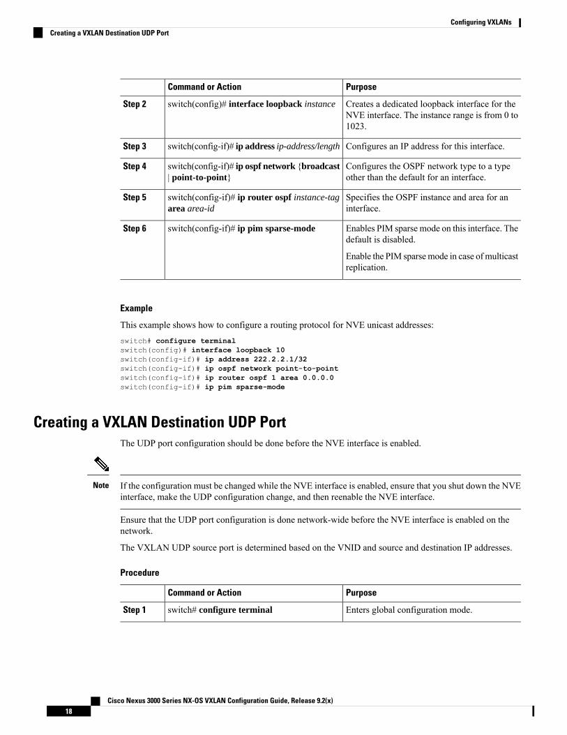
PurposeCommand or Action
Creates a dedicated loopback interface for theNVE interface. The instance range is from 0 to1023.
switch(config)# interface loopback instanceStep 2
Configures an IP address for this interface.switch(config-if)# ip address ip-address/lengthStep 3
Configures the OSPF network type to a typeother than the default for an interface.
switch(config-if)# ip ospf network {broadcast| point-to-point}
Step 4
Specifies the OSPF instance and area for aninterface.
switch(config-if)# ip router ospf instance-tagarea area-id
Step 5
Enables PIM sparse mode on this interface. Thedefault is disabled.
switch(config-if)# ip pim sparse-modeStep 6
Enable the PIM sparsemode in case of multicastreplication.
Example
This example shows how to configure a routing protocol for NVE unicast addresses:switch# configure terminalswitch(config)# interface loopback 10switch(config-if)# ip address 222.2.2.1/32switch(config-if)# ip ospf network point-to-pointswitch(config-if)# ip router ospf 1 area 0.0.0.0switch(config-if)# ip pim sparse-mode
Creating a VXLAN Destination UDP PortThe UDP port configuration should be done before the NVE interface is enabled.
If the configuration must be changed while the NVE interface is enabled, ensure that you shut down the NVEinterface, make the UDP configuration change, and then reenable the NVE interface.
Note
Ensure that the UDP port configuration is done network-wide before the NVE interface is enabled on thenetwork.
The VXLAN UDP source port is determined based on the VNID and source and destination IP addresses.
Procedure
PurposeCommand or Action
Enters global configuration mode.switch# configure terminalStep 1
Cisco Nexus 3000 Series NX-OS VXLAN Configuration Guide, Release 9.2(x)18
Configuring VXLANsCreating a VXLAN Destination UDP Port

PurposeCommand or Action
Specifies the destination UDP port number forVXLAN encapsulated packets. The defaultdestination UDP port number is 4789.
switch(config)# vxlan udp port numberStep 2
Example
This example shows how to create a VXLAN destination UDP port:switch# configure terminalswitch(config)# vxlan udp port 4789
Creating and Configuring an NVE InterfaceAn NVE interface is the overlay interface that initiates and terminates VXLAN tunnels. You can create andconfigure an NVE (overlay) interface.
Procedure
PurposeCommand or Action
Enters global configuration mode.switch# configure terminalStep 1
Creates a VXLAN overlay interface thatinitiates and terminates VXLAN tunnels.
switch(config)# interface nve instanceStep 2
Only one NVE interface is allowedon the switch.
Note
Specifies a source interface.switch(config-if-nve)# source-interfaceloopback instance
Step 3
The source interface must be a loopbackinterface that is configured on the switch witha valid /32 IP address. This /32 IP address mustbe known by the transit routers in the transportnetwork and the remote VTEPs.
Example
This example shows how to create and configure an NVE interface:switch# configure terminalswitch(config)# interface nve 1switch(config-if-nve)# source-interface loopback 10
Configuring Replication for a VNIReplication for VXLAN network identifier (VNI) can be configured in one of two ways:
• Multicast replication
Cisco Nexus 3000 Series NX-OS VXLAN Configuration Guide, Release 9.2(x)19
Configuring VXLANsCreating and Configuring an NVE Interface

• Ingress replication
Configuring Multicast Replication
Before you begin
• Ensure that the NVE interface is created and configured.
• Ensure that the source interface is specified.
Procedure
PurposeCommand or Action
Maps VXLAN VNIs to the NVE interface andassigns a multicast group to the VNIs.
switch(config-if-nve)# member vni {vnidmcast-group multicast-group-addr | vnid-range mcast-group start-addr [end-addr]}
Step 1
Example
This example shows how to map a VNI to an NVE interface and assign it to a multicast group:switch(config-if-nve)# member vni 5000 mcast-group 225.1.1.1
Configuring Ingress Replication
Before you begin
• Ensure that the NVE interface is created and configured.
• Ensure that the source interface is specified.
Procedure
PurposeCommand or Action
Maps VXLAN VNIs to the NVE interface.switch(config-if-nve)# member vni vnidStep 1
Enables static ingress replication for the VNI.switch(config-if-nve-vni)# ingress-replicationprotocol static
Step 2
Enables the peer IP.switch(config-if-nve-vni)# peer-ip ip-addressStep 3
• A VNI can be associated onlywith a single IP address.
• An IP address can be associatedonly with a single VNI.
Note
Cisco Nexus 3000 Series NX-OS VXLAN Configuration Guide, Release 9.2(x)20
Configuring VXLANsConfiguring Multicast Replication

Example
This example shows how to map a VNI to an NVE interface and create a unicast tunnel:switch(config-if-nve)# member vni 5001switch(config-if-nve-vni)# ingress-replication protocol staticswitch(config-if-nve-vni)# peer-ip 111.1.1.1
Configuring Q-in-VNIUsing Q-in-VNI provides a way for you to segregate traffic by mapping to a specific port. In a multi-tenantenvironment, you can specify a port to a tenant and send/receive packets over the VXLAN overlay.
Notes about configuring Q-in-VNI:
• Q-in-VNI is supported only for the 31108PC-V, 31108TC-V, 3132Q-V, and 3132C-Z platform switches.
• The dot1q mode is not supported for 40G ports.
• Q-in-Q to Q-in-VNI interworking is supported.
• Q-in-VNI only supports VXLAN bridging. It does not support VXLAN routing.
• Q-in-VNI does not support FEX.
• When configuring access ports and trunk ports:
• You can have access ports, trunk ports and dot1q ports on different interfaces on the same switch.
• You cannot have the same VLAN configured for both dot1q and trunk ports/access ports.
Before you begin
Configuring the Q-in-VNI feature requires:
• The base port mode must be a dot1q tunnel port with an access VLAN configured.
• VNI mapping is required for the access VLAN on the port.
Procedure
PurposeCommand or Action
Enters global configuration mode.configure terminalStep 1
Enters interface configuration mode.interface type portStep 2
Creates a 802.1Q tunnel on the port.switchport mode dot1q-tunnelStep 3
Specifies the port assigned to a VLAN.switchport access vlan vlan-idStep 4
Enables BPDU Filtering for the specifiedspanning tree edge interface. By default, BPDUFiltering is disabled.
spanning-tree bpdufilter enableStep 5
Cisco Nexus 3000 Series NX-OS VXLAN Configuration Guide, Release 9.2(x)21
Configuring VXLANsConfiguring Q-in-VNI

Example
The following example shows how to configure Q-in-VNI:
switch# config terminalswitch(config)# interface ethernet 1/4switch(config-if)# switchport mode dot1q-tunnelswitch(config-if)# switchport access vlan 10switch(config-if)# spanning-tree bpdufilter enableswitch(config-if)#
Verifying the VXLAN ConfigurationUse one of the following commands to verify the VXLAN configuration, to display the MAC addresses, andto clear the MAC addresses:
PurposeCommand
Displays the configuration of an NVE interface.show nve interface nve id
Displays the VNI that is mapped to an NVE interface.show nve vni
Displays peers of the NVE interface.show nve peers
Displays all the counters for an NVE interface.show interface nve id counters
Displays the VXLAN UDP port configured.show nve vxlan-params
Displays both VLAN and VXLAN MAC addresses.show mac address-table
Clears all MAC address entries in the MAC address table.clear mac address-table dynamic
Example
This example shows how to display the configuration of an NVE interface:switch# show nve interface nve 1Interface: nve1, State: up, encapsulation: VXLANSource-interface: loopback10 (primary: 111.1.1.1, secondary: 0.0.0.0)
This example shows how to display the VNI that is mapped to an NVE interface for multicastreplication:switch# show nve vniInterface VNI Multicast-group VNI State---------------- -------- --------------- ---------nve1 5000 225.1.1.1 Up
This example shows how to display the VNI that is mapped to an NVE interface for ingress replication:
Cisco Nexus 3000 Series NX-OS VXLAN Configuration Guide, Release 9.2(x)22
Configuring VXLANsVerifying the VXLAN Configuration

switch# show nve vniInterface VNI Multicast-group VNI State---------------- -------- --------------- ---------nve1 5000 0.0.0.0 Up
This example shows how to display the peers of an NVE interface:switch# show nve peersInterface Peer-IP Peer-State---------------- --------------- -------------nve1 111.1.1.1 Up
This example shows how to display the counters of an NVE interface:switch# show interface nv 1 counter
--------------------------------------------------------------------------------Port InOctets InUcastPkts--------------------------------------------------------------------------------nve1 0 0
--------------------------------------------------------------------------------Port InMcastPkts InBcastPkts--------------------------------------------------------------------------------nve1 0 0
--------------------------------------------------------------------------------Port OutOctets OutUcastPkts--------------------------------------------------------------------------------nve1 0 0
--------------------------------------------------------------------------------Port OutMcastPkts OutBcastPkts--------------------------------------------------------------------------------nve1 0 0
This example shows how to display the VXLAN UDP port configured:switch# show nve vxlan-paramsVxLAN Dest. UDP Port: 4789
This example shows how to display both VLAN and VXLAN MAC addresses:switch# show mac address-tableLegend:
* - primary entry, G - Gateway MAC, (R) - Routed MAC, O - Overlay MACage - seconds since first seen,+ - primary entry using vPC Peer-Link
VLAN MAC Address Type age Secure NTFY Ports/SWID.SSID.LID---------+-----------------+--------+---------+------+----+------------------* 109 0000.0410.0902 dynamic 470 F F Po2233* 109 0000.0410.0912 dynamic 470 F F Po2233* 109 0000.0410.0912 dynamic 470 F F nve1(1.1.1.200)* 108 0000.0410.0802 dynamic 470 F F Po2233* 108 0000.0410.0812 dynamic 470 F F Po2233* 107 0000.0410.0702 dynamic 470 F F Po2233* 107 0000.0410.0712 dynamic 470 F F Po2233* 107 0000.0410.0712 dynamic 470 F F nve1(1.1.1.200)* 106 0000.0410.0602 dynamic 470 F F Po2233* 106 0000.0410.0612 dynamic 470 F F Po2233* 105 0000.0410.0502 dynamic 470 F F Po2233* 105 0000.0410.0512 dynamic 470 F F Po2233* 105 0000.0410.0512 dynamic 470 F F nve1(1.1.1.200)
Cisco Nexus 3000 Series NX-OS VXLAN Configuration Guide, Release 9.2(x)23
Configuring VXLANsVerifying the VXLAN Configuration

* 104 0000.0410.0402 dynamic 470 F F Po2233* 104 0000.0410.0412 dynamic 470 F F Po2233
This example shows how to clear all MAC address entries in the MAC address table:switch# clear mac address-table dynamicswitch#
Cisco Nexus 3000 Series NX-OS VXLAN Configuration Guide, Release 9.2(x)24
Configuring VXLANsVerifying the VXLAN Configuration
C H A P T E R 3IGMP Snooping Over VXLAN
•
• Overview of IGMP Snooping Over VXLAN, on page 25• Guidelines and Limitations for IGMP Snooping Over VXLAN, on page 25• Configuring IGMP Snooping Over VXLAN, on page 26
Overview of IGMP Snooping Over VXLANThe configuration of IGMP snooping is same in VXLAN as in configuration of IGMP snooping in regularVLAN domain. All the configuration CLIs remain the same. For more information on IGMP snooping, seethe Configuring IGMP Snooping section in Cisco Nexus 3000 Series NX-OS Multicast Routing ConfigurationGuide, Release 7.x.
Guidelines and Limitations for IGMP Snooping Over VXLANSee the following guidelines and limitations for IGMP snooping over VXLAN:
• Cisco Nexus 3500 Series switches support IGMP Snooping Over VXLAN.
• Starting with Release 7.0(3)I5(1), IGMP snooping over VXLAN is supported.
• IGMP snooping on VXLAN VLAN is disabled by default.
• For IGMP snooping over VXLAN, all the guidelines and limitations of VXLAN apply.
• IGMP snooping over VXLAN is not supported on any FEX enabled platforms and FEX ports.
• IGMP snooping over VXLANVLAN is supported on C3132Q-V, C31108PC-V, C31108TC-V, C3132Q(N9K mode only), 3172 (N9K mode only)
Cisco Nexus 3000 Series NX-OS VXLAN Configuration Guide, Release 9.2(x)25

Configuring IGMP Snooping Over VXLANBefore you begin
For VXLAN IGMP snooping functionality, the ARP-ETHER TCAMmust be configured in the double-widemode using the CLI command, switch# hardware access-list tcam region arp-ether 256 double wide.
Procedure
PurposeCommand or Action
Enables IGMP snooping for VXLAN VLANs.You have to explicitly configure this commandto enable snooping for VXLAN VLANs.
switch(config)#ip igmp snooping vxlanStep 1
Configures IGMP snooping over VXLAN tonot include NVE as static mrouter port using
switch(config)#ip igmp snoopingdisable-nve-static-router-port
Step 2
this global CLI command. IGMP snooping overVXLAN has the NVE interface as mrouter portby default.
Configures the VXLAN global IPMC indexsize. IGMP snooping over VXLAN uses the
switch(config)#system nve ipmc globalindex-size ?
Step 3
IPMC indexes from the NVE global range onExample: the Cisco Nexus 3000 Series switches with
switch(config)# system nve ipmc globalNetwork Forwarding Engine (NFE). You needto reconfigure the VXLAN global IPMC indexindex-size ?
<1000-7000> Ipmc allowed size size according to the scale using this command.Cisco recommends to reserve 6000 IPMCindexes using this CLI command. The defaultIPMC index size is 3000.
Configures IGMP snooping over VXLAN todrop all the unknown multicast traffic on per
switch(config)# ip igmp snooping vxlan-umcdrop vlan ?
Step 4
VLAN basis using this global CLI command.Example: On Cisco Nexus 3000 Series switches with
switch(config)# ip igmp snoopingNetwork Forwarding Engine (NFE), the defaultbehavior of all unknown multicast traffic is toflood to the bridge domain.
vxlan-umc drop vlan ?<1-3863> VLAN IDs for which unknownmulticast traffic is dropped
IPv6 neighbor solicitation packetsare dropped when this command isenabled. Therefore, IPv6 hosts arenot resolved.
Note
Cisco Nexus 3000 Series NX-OS VXLAN Configuration Guide, Release 9.2(x)26
IGMP Snooping Over VXLANConfiguring IGMP Snooping Over VXLAN

C H A P T E R 4Configuring VXLAN BGP EVPN
This chapter contains the following sections:
• Information About VXLAN BGP EVPN, on page 27• Configuring VXLAN BGP EVPN, on page 35• Verifying the VXLAN BGP EVPN Configuration, on page 45• Example of VXLAN BGP EVPN (EBGP), on page 46• Example of VXLAN BGP EVPN (IBGP), on page 57• Example Show Commands, on page 68• VXLAN Cross Connect, on page 70
Information About VXLAN BGP EVPN
Guidelines and Limitations for VXLAN BGP EVPNVXLAN BGP EVPN has the following guidelines and limitations:
• Routing between VXLAN VLANs and non-VXLAN VLANs, and Layer 3 interfaces, is not supportedon Cisco Nexus 3100-V. Hence, Cisco Nexus 3100-V cannot be a border leaf VTEP in a VXLAN EVPNsetup.
• You can configure EVPN over segment routing or MPLS. See the Cisco Nexus 3000 Series NX-OSLabel Switching Configuration Guide, Release 9.2(x) for more information.
• You can use MPLS tunnel encapsulation using the new CLI encapsulation mpls command. You canconfigure the label allocation mode for the EVPN address family. See the Cisco Nexus 3000 SeriesNX-OS Label Switching Configuration Guide, Release 9.2(x) for more information.
• In VXLAN EVPN setup that has 2K VNI scale configuration, the control plane down time takes morethan 200 seconds. To avoid BGP flap, configure the graceful restart time to 300 seconds.
• SVI and sub-interfaces as core links are not supported in multisite EVPN.
• In a VXLAN EVPN setup, border leaves must use unique route distinguishers, preferably using autord command. It is not supported to have same route distinguishers in different border leaves.
• ARP suppression is only supported for a VNI if the VTEP hosts the First-Hop Gateway (DistributedAnycast Gateway) for this VNI. The VTEP and the SVI for this VLAN have to be properly configured
Cisco Nexus 3000 Series NX-OS VXLAN Configuration Guide, Release 9.2(x)27

for the distributed Anycast Gateway operation, for example, global Anycast Gateway MAC addressconfigured and Anycast Gateway feature with the virtual IP address on the SVI.
• When Layer 3 EVPN is configured in Cisco Nexus 3000 Series switches that are based on BroadcomASIC and these switches are added in the topology with Layer 2 EVPN, the routing for this scenario isnot supported. When you configure SVI and Layer 3 EVPN in Cisco Nexus 3000 Series switches basedon Broadcom ASIC with Anycast Gateway and when you send the ARP requests from a Layer 2 EVPNdevice (for example, Cisco Nexus 3000 Series switches, based on a Broadcom ASIC), the Cisco Nexus3000 Series switches can not be used as a gateway for the ARP requests received on the network ports.
• The show commands with the internal keyword are not supported.
• DHCP snooping (Dynamic Host Configuration Protocol snooping) is not supported on VXLANVLANs.
• SPAN TX for VXLAN encapsulated traffic is not supported for the Layer 3 uplink interface.
• RACLs are not supported on Layer 3 uplinks for VXLAN traffic. Egress VACLs support is not availablefor de-capsulated packets in the network to access direction on the inner payload.
As a best practice, use PACLs/VACLs for the access to the network direction.
• QoS classification is not supported for VXLAN traffic in the network to access direction on the Layer3 uplink interface.
• The QoS buffer-boost feature is not applicable for VXLAN traffic.
• VTEP does not support Layer 3 subinterface uplinks that carry VXLAN encapsulated traffic.
• Layer 3 interface uplinks that carry VXLAN encapsulated traffic do not support subinterfaces fornon-VxLAN encapsulated traffic.
• Non-VXLAN sub-interface VLANs cannot be shared with VXLAN VLANs.
• Subinterfaces on 40G (ALE) uplink ports are not supported on VXLAN VTEPs.
• Point to multipoint Layer 3 and SVI uplinks are not supported. Since both uplink types can only beenabled point-to-point, they cannot span across more than two switches.
• For EBGP, it is recommended to use a single overlay EBGP EVPN session between loopbacks.
• Bind NVE to a loopback address that is separate from other loopback addresses that are required byLayer 3 protocols. A best practice is to use a dedicated loopback address for VXLAN.
• VXLAN BGP EVPN does not support an NVE interface in a non-default VRF.
• It is recommended to configure a single BGP session over the loopback for an overlay BGP session.
• The VXLAN UDP port number is used for VXLAN encapsulation. For Cisco Nexus NX-OS, the UDPport number is 4789. It complies with IETF standards and is not configurable.
• VXLAN supports In Service Software Upgrade (ISSU).
• VTEP connected to FEX host interface ports is not supported.
• Resilient hashing (port-channel load-balancing resiliency) and VXLAN configurations are not compatiblewith VTEPs using ALE uplink ports.
Cisco Nexus 3000 Series NX-OS VXLAN Configuration Guide, Release 9.2(x)28
Configuring VXLAN BGP EVPNGuidelines and Limitations for VXLAN BGP EVPN
Resilient hashing is disabled by default.Note
Notes for EVPN ConvergenceThe following are notes about EVPN Convergence (7.0(3)I3(1) and later):
• As a best practice, the NVE source loopback should be dedicated to NVE. so that NVE can bring theloopback up or down as needed.
• When vPC has been configured, the loopback stays down until the MCT link comes up.
When feature vpc is enabled and there is no VPC configured, the NVE sourceloopback is in "shutdown" state after an upgrade. In this case, removing featurevpc restores the interface to "up" state."
Note
• The NVE underlay (through the source loopback) is kept down until the overlay has converged.
• When MCT comes up, the source loopback is kept down for an amount of time that is configurable.This approach prevents north-south traffic from coming in until the overlay has converged.
• When MCT goes down, NVE is kept up for 30 seconds in the event that there is still south-northtraffic from vPC legs which have not yet gone down.
• BGP ignores routes from vPC peer. This reduces the number of routes in BGP.
Considerations for VXLAN BGP EVPN Deployment• A loopback address is required when using the source-interface config command. The loopback addressrepresents the local VTEP IP.
• During boot-up of a switch (7.0(3)I2(2) and later), you can use the source-interface hold-down-timehold-down-time command to suppress advertisement of the NVE loopback address until the overlay hasconverged. The range for the hold-down-time is 0 - 2147483647 seconds. The default is 300 seconds.
• To establish IP multicast routing in the core, IP multicast configuration, PIM configuration, and RPconfiguration is required.
• VTEP to VTEP unicast reachability can be configured through any IGP/BGP protocol.
• If the anycast gateway feature is enabled for a specific VNI, then the anyway gateway feature must beenabled on all VTEPs that have that VNI configured. Having the anycast gateway feature configured ononly some of the VTEPs enabled for a specific VNI is not supported.
• It is a requirement when changing the primary or secondary IP address of the NVE source interfaces toshut the NVE interface before changing the IP address.
• As a best practice, the RP for the multicast group should be configured only on the spine layer. Use theanycast RP for RP load balancing and redundancy.
• Every tenant VRF needs a VRF overlay VLAN and SVI for VXLAN routing.
Cisco Nexus 3000 Series NX-OS VXLAN Configuration Guide, Release 9.2(x)29
Configuring VXLAN BGP EVPNNotes for EVPN Convergence

• When configuring ARP suppression with BGP-EVPN, use the hardware access-list tcam regionarp-ether size double-wide command to accommodate ARP in this region. (You must decrease the sizeof an existing TCAM region before using this command.)
VPC Considerations for VXLAN BGP EVPN Deployment• The loopback address used by NVE needs to be configured to have a primary IP address and a secondaryIP address.
The secondary IP address is used for all VxLAN traffic that includes multicast and unicast encapsulatedtraffic.
• Each VPC peer needs to have separate BGP sessions to the spine.
• VPC peers must have identical configurations.
• Consistent VLAN to VN-segment mapping.
• Consistent NVE1 binding to the same loopback interface
• Using the same secondary IP address.
• Using different primary IP addresses.
• Consistent VNI to group mapping.
• The VRF overlay VLAN should be a member of the peer-link port-channel.
• For multicast, the VPC node that receives the (S, G) join from the RP (rendezvous point) becomes theDF (designated forwarder). On the DF node, encap routes are installed for multicast.
Decap routes are installed based on the election of a decapper from between the VPC primary node andthe VPC secondary node. The winner of the decap election is the node with the least cost to the RP.However, if the cost to the RP is the same for both nodes, the VPC primary node is elected.
The winner of the decap election has the decap mroute installed. The other node does not have a decaproute installed.
• On a VPC device, BUM traffic (broadcast, unknown-unicast, andmulticast traffic) from hosts is replicatedon the peer-link. A copy is made of every native packet and each native packet is sent across the peer-linkto service orphan-ports connected to the peer VPC switch.
To prevent traffic loops in VXLAN networks, native packets ingressing the peer-link cannot be sent toan uplink. However, if the peer switch is the encapper, the copied packet traverses the peer-link and issent to the uplink.
Each copied packet is sent on a special internal VLAN (VLAN 4041).Note
• When peer-link is shut, the loopback interface used by NVE on the VPC secondary is brought down andthe status is Admin Shut. This is done so that the route to the loopback is withdrawn on the upstreamand that the upstream can divert all traffic to the VPC primary.
Cisco Nexus 3000 Series NX-OS VXLAN Configuration Guide, Release 9.2(x)30
Configuring VXLAN BGP EVPNVPC Considerations for VXLAN BGP EVPN Deployment

Orphans connected to the VPC secondary will experience loss of traffic for theperiod that the peer-link is shut. This is similar to Layer 2 orphans in a VPCsecondary of a traditional VPC setup.
Note
• When peer-link is no-shut, the NVE loopback address is brought up again and the route is advertisedupstream, attracting traffic.
• For VPC, the loopback interface has 2 IP addresses: the primary IP address and the secondary IP address.
The primary IP address is unique and is used by Layer 3 protocols.
The secondary IP address on loopback is necessary because the interface NVE uses it for the VTEP IPaddress. The secondary IP address must be same on both vPC peers.
• The VPC peer-gateway feature must be enabled on both peers.
As a best practice, use peer-switch, peer gateway, ip arp sync, ipv6 nd sync configurations for improvedconvergence in VPC topologies.
In addition, increase the STP hello timer to 4 seconds to avoid unnecessary TCN generations when VPCrole changes occur.
The following is an example (best practice) of a VPC configuration:
switch# sh ru vpc
version 6.1(2)I3(1)feature vpcvpc domain 2peer-switchpeer-keepalive destination 172.29.206.65 source 172.29.206.64peer-gatewayipv6 nd synchronizeip arp synchronize
• On a VPC pair, shutting down NVE or NVE loopback on one of the VPC nodes is not a supportedconfiguration. This means that traffic failover on one-side NVE shut or one-side loopback shut is notsupported.
• Redundant anycast RPs configured in the network for multicast load-balancing and RP redundancy aresupported on VPC VTEP topologies.
• Enabling vpc peer-gateway configuration is mandatory. For peer-gateway functionality, at least onebackup routing SVI is required to be enabled across peer-link and also configured with PIM. This providesa backup routing path in the case when VTEP loses complete connectivity to the spine. Remote peerreachability is re-routed over the peer-link in this case.
The following is an example of SVI with PIM enabled:
swithch# sh ru int vlan 2
interface Vlan2description special_svi_over_peer-linkno shutdownip address 30.2.1.1/30
Cisco Nexus 3000 Series NX-OS VXLAN Configuration Guide, Release 9.2(x)31
Configuring VXLAN BGP EVPNVPC Considerations for VXLAN BGP EVPN Deployment

ip pim sparse-mode
The SVI must be configured on both VPC peers and requires PIM to be enabled.Note
• As a best practice when changing the secondary IP address of an anycast VPCVTEP, the NVE interfaceson both the VPC primary and the VPC secondary should be shut before the IP changes are made.
• To provide redundancy and failover of VXLAN traffic when a VTEP loses all of its uplinks to the spine,it is recommended to run a Layer 3 link or an SVI link over the peer-link between VPC peers.
• If DHCP Relay is required in VRF for DHCP clients or if loopback in VRF is required for reachabilitytest on a VPC pair, it is necessary to create a backup SVI per VRF with PIM enabled.
swithch# sh ru int vlan 20
interface Vlan20description backup routing svi for VRF Greenvrf member GREENno shutdownip address 30.2.10.1/30
Network Considerations for VXLAN Deployments• MTU Size in the Transport Network
Due to the MAC-to-UDP encapsulation, VXLAN introduces 50-byte overhead to the original frames.Therefore, the maximum transmission unit (MTU) in the transport network needs to be increased by 50bytes. If the overlays use a 1500-byteMTU, the transport network needs to be configured to accommodate1550-byte packets at a minimum. Jumbo-frame support in the transport network is required if the overlayapplications tend to use larger frame sizes than 1500 bytes.
• ECMP and LACP Hashing Algorithms in the Transport Network
As described in a previous section, Cisco Nexus 3000 Series Switches introduce a level of entropy inthe source UDP port for ECMP and LACP hashing in the transport network. As a way to augment thisimplementation, the transport network uses an ECMP or LACP hashing algorithm that takes the UDPsource port as an input for hashing, which achieves the best load-sharing results for VXLAN encapsulatedtraffic.
• Multicast Group Scaling
The VXLAN implementation on Cisco Nexus 3000 Series Switches uses multicast tunnels for broadcast,unknown unicast, and multicast traffic forwarding. Ideally, one VXLAN segment mapping to one IPmulticast group is the way to provide the optimal multicast forwarding. It is possible, however, to havemultiple VXLAN segments share a single IP multicast group in the core network. VXLAN can supportup to 16 million logical Layer 2 segments, using the 24-bit VNID field in the header. With one-to-onemapping between VXLAN segments and IP multicast groups, an increase in the number of VXLANsegments causes a parallel increase in the required multicast address space and the amount of forwardingstates on the core network devices. At some point, multicast scalability in the transport network canbecome a concern. In this case, mapping multiple VXLAN segments to a single multicast group can helpconservemulticast control plane resources on the core devices and achieve the desired VXLAN scalability.However, this mapping comes at the cost of suboptimal multicast forwarding. Packets forwarded to the
Cisco Nexus 3000 Series NX-OS VXLAN Configuration Guide, Release 9.2(x)32
Configuring VXLAN BGP EVPNNetwork Considerations for VXLAN Deployments
multicast group for one tenant are now sent to the VTEPs of other tenants that are sharing the samemulticast group. This causes inefficient utilization of multicast data plane resources. Therefore, thissolution is a trade-off between control plane scalability and data plane efficiency.
Despite the suboptimal multicast replication and forwarding, having multiple-tenant VXLAN networksto share a multicast group does not bring any implications to the Layer 2 isolation between the tenantnetworks. After receiving an encapsulated packet from the multicast group, a VTEP checks and validatesthe VNID in the VXLAN header of the packet. The VTEP discards the packet if the VNID is unknownto it. Only when the VNID matches one of the VTEP’s local VXLAN VNIDs, does it forward the packetto that VXLAN segment. Other tenant networks will not receive the packet. Thus, the segregation betweenVXLAN segments is not compromised.
Considerations for the Transport NetworkThe following are considerations for the configuration of the transport network:
• On the VTEP device:
• Enable and configure IP multicast.*
• Create and configure a loopback interface with a /32 IP address.
(For vPC VTEPs, you must configure primary and secondary /32 IP addresses.)
• Enable IP multicast on the loopback interface.*
• Advertise the loopback interface /32 addresses through the routing protocol (static route) that runsin the transport network.
• Enable IP multicast on the uplink outgoing physical interface.*
• Throughout the transport network:
• Enable and configure IP multicast.*
• When using SVI uplinks with VXLAN enabled on Cisco Nexus 9200 platform switches and Cisco Nexus9300-EX platform switches, use the system nve infra-vlans command to specify the VLANs that areused for uplink SVI. Failing to specify the VLANs results in traffic loss.
• The system nve infra-vlans command specifies VLANs used by all SVIinterfaces for uplink and vPC peer-links in VXLAN as infra-VLANs.
• You should not configure certain combinations of infra-VLANs. For example,2 and 514, 10 and 522, which are 512 apart.
Note
* Not required for static ingress replication or BGP EVPN ingress replication.Note
Cisco Nexus 3000 Series NX-OS VXLAN Configuration Guide, Release 9.2(x)33
Configuring VXLAN BGP EVPNConsiderations for the Transport Network
BGP EVPN Considerations for VXLAN Deployment
Commands for BGP EVPN
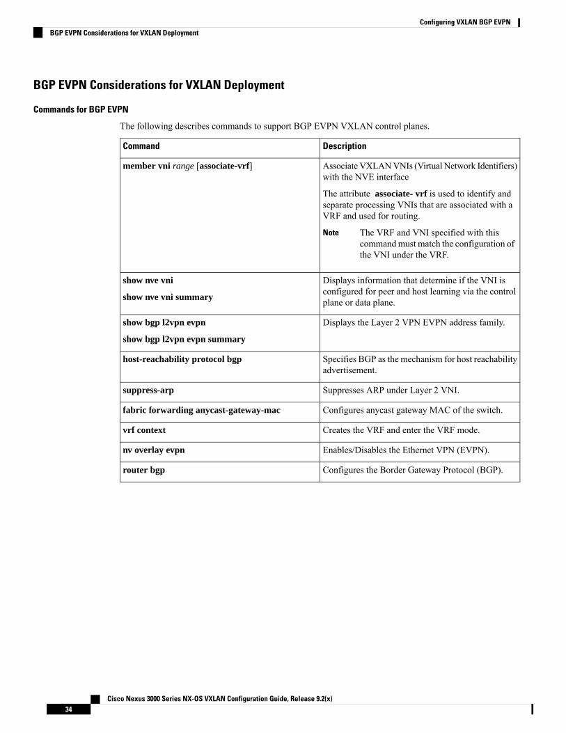
The following describes commands to support BGP EVPN VXLAN control planes.
DescriptionCommand
Associate VXLANVNIs (Virtual Network Identifiers)with the NVE interface
The attribute associate- vrf is used to identify andseparate processing VNIs that are associated with aVRF and used for routing.
The VRF and VNI specified with thiscommandmust match the configuration ofthe VNI under the VRF.
Note
member vni range [associate-vrf]
Displays information that determine if the VNI isconfigured for peer and host learning via the controlplane or data plane.
show nve vni
show nve vni summary
Displays the Layer 2 VPN EVPN address family.show bgp l2vpn evpn
show bgp l2vpn evpn summary
Specifies BGP as the mechanism for host reachabilityadvertisement.
host-reachability protocol bgp
Suppresses ARP under Layer 2 VNI.suppress-arp
Configures anycast gateway MAC of the switch.fabric forwarding anycast-gateway-mac
Creates the VRF and enter the VRF mode.vrf context
Enables/Disables the Ethernet VPN (EVPN).nv overlay evpn
Configures the Border Gateway Protocol (BGP).router bgp
Cisco Nexus 3000 Series NX-OS VXLAN Configuration Guide, Release 9.2(x)34
Configuring VXLAN BGP EVPNBGP EVPN Considerations for VXLAN Deployment

DescriptionCommand
Suppresses the BGP MAC route so that BGP onlysends the MAC/IP route for a host.
Under NVE, the MAC updates for all VNIs aresuppressed.
Note • Receive-side — Suppressing theMAC route depends upon thecapability of the remote EVPN peerto derive a MAC route from theMAC/IP route (7.0(3)I2(2) and later).Avoid using the “suppress mac-route”command if devices in the networkare running an earlier NX-OS release.
• Send-side — Suppressing the MACroute means that the sender has aMAC/IP route. If your configurationhas pure-Layer 2 VNIs (such as nocorresponding VRF or Layer3-VNI),then there is no correspondingMAC/IP and you should avoid usingthe “suppress mac-route” command.
suppress mac-route
Configuring VXLAN BGP EVPN
Enabling VXLANEnable VXLAN and the EVPN.
Procedure
PurposeCommand or Action
Enable VLAN-based VXLANfeature vn-segmentStep 1
Enable VXLANfeature nv overlayStep 2
Enable the EVPN control plane for VXLAN.nv overlay evpnStep 3
Cisco Nexus 3000 Series NX-OS VXLAN Configuration Guide, Release 9.2(x)35
Configuring VXLAN BGP EVPNConfiguring VXLAN BGP EVPN

Configuring VLAN and VXLAN VNI
Procedure
PurposeCommand or Action
Specify VLAN.vlan numberStep 1
MapVLAN toVXLANVNI to configure Layer2 VNI under VXLAN VLAN.
vn-segment numberStep 2
Configuring VRF for VXLAN RoutingConfigure the tenant VRF.
Procedure
PurposeCommand or Action
Configure the VRF.vrf context vxlanStep 1
Specify VNI.vni numberStep 2
Specify VRF RD (route distinguisher).rd autoStep 3
Configure address family for IPv4.address-family ipv4 unicastStep 4
route-target both autoStep 5 Specifying the auto option isapplicable only for IBGP.
Manually configured route targetsare required for EBGP.
Note
route-target both auto evpnStep 6 Specifying the auto option isapplicable only for IBGP. The autooption is available beginning withCisco NX-OS Release 7.0(3)I7(1).
Manually configured route targetsare required for EBGP.
Note
Configure address family for IPv6.address-family ipv6 unicastStep 7
route-target both autoStep 8 Specifying the auto option isapplicable only for IBGP. The autooption is available beginning withCisco NX-OS Release 7.0(3)I7(1).
Manually configured route targetsare required for EBGP.
Note
Cisco Nexus 3000 Series NX-OS VXLAN Configuration Guide, Release 9.2(x)36
Configuring VXLAN BGP EVPNConfiguring VLAN and VXLAN VNI

PurposeCommand or Action
route-target both auto evpnStep 9 Specifying the auto option isapplicable only for IBGP.
Manually configured route targetsare required for EBGP.
Note
Configuring SVI for Hosts for VXLAN RoutingConfigure the SVI for hosts.
Procedure
PurposeCommand or Action
Specify VLANvlan numberStep 1
Specify VLAN interface.interface vlan-numberStep 2
Configure SVI for host.vrf member vxlan-numberStep 3
Specify IP address.ip address addressStep 4
Configuring VRF Overlay VLAN for VXLAN Routing
Procedure
PurposeCommand or Action
Specify VLAN.vlan numberStep 1
Specify vn-segment.vn-segment numberStep 2
Configuring VNI Under VRF for VXLAN RoutingConfigures a Layer 3 VNI under a VRF overlay VLAN. (A VRF overlay VLAN is a VLAN that is notassociated with any server facing ports. All VXLAN VNIs that are mapped to a VRF, need to have their owninternal VLANs allocated to it.)
Procedure
PurposeCommand or Action
Create a VXLAN Tenant VRFvrf context vxlanStep 1
Configure Layer 3 VNI under VRF.vni numberStep 2
Cisco Nexus 3000 Series NX-OS VXLAN Configuration Guide, Release 9.2(x)37
Configuring VXLAN BGP EVPNConfiguring SVI for Hosts for VXLAN Routing

Configuring Anycast Gateway for VXLAN Routing
Procedure
PurposeCommand or Action
Configure distributed gateway virtual MACaddress
fabric forwarding anycast-gateway-macaddress
Step 1
One virtual MAC per VTEPNote
All VTEPs should have the samevirtual MAC address
Note
Associate SVI with anycast gateway underVLAN configuration mode.
fabric forwarding mode anycast-gatewayStep 2
Configuring the NVE Interface and VNIs
Procedure
PurposeCommand or Action
Configure the NVE interface.interface nve-interfaceStep 1
This defines BGP as the mechanism for hostreachability advertisement
host-reachability protocol bgpStep 2
Add Layer-3 VNIs, one per tenant VRF, to theoverlay.
member vni vni associate-vrfStep 3
Required for VXLAN routing only.Note
global mcast-group ip-addressStep 4
Add Layer 2 VNIs to the tunnel interface.member vni vniStep 5
Configure the mcast group on a per-VNI basismcast-group addressStep 6
Configuring BGP on the VTEP
Procedure
PurposeCommand or Action
Configure BGP.router bgp numberStep 1
Specify router address.router-id addressStep 2
Cisco Nexus 3000 Series NX-OS VXLAN Configuration Guide, Release 9.2(x)38
Configuring VXLAN BGP EVPNConfiguring Anycast Gateway for VXLAN Routing

PurposeCommand or Action
Define MP-BGP neighbors. Under eachneighbor define l2vpn evpn.
neighbor address remote-as numberStep 3
Configure address family for IPv4.address-family ipv4 unicastStep 4
Configure address family Layer 2 VPNEVPNunder the BGP neighbor.
address-family l2vpn evpnStep 5
Address-family ipv4 evpn for vxlanhost-based routing
Note
Allows duplicate AS numbers in the AS path.Configure this parameter on the leaf for eBGP
(Optional) Allowas-inStep 6
when all leafs are using the same AS, but thespines have a different AS than leafs.
Configures community for BGP neighbors.send-community extendedStep 7
Specify VRF.vrf vrf-nameStep 8
Configure address family for IPv4.address-family ipv4 unicastStep 9
Enable advertising EVPN routes.advertise l2vpn evpnStep 10
Beginning with Cisco NX-OSRelease 9.2(1), the advertise l2vpnevpn command no longer takeseffect. To disable advertisement fora VRF toward the EVPN, disablethe VNI in NVE by entering the nomember vni vni associate-vrfcommand in interface nve1. The vniis the VNI associated with thatparticular VRF.
Note
Configure address family for IPv6.address-family ipv6 unicastStep 11
Enable advertising EVPN routes.advertise l2vpn evpnStep 12
Configuring RD and Route Targets for VXLAN Bridging
Procedure
PurposeCommand or Action
Configure VRF.evpnStep 1
vni number l2Step 2 Only Layer 2 VNIs need to bespecified.
Note
Cisco Nexus 3000 Series NX-OS VXLAN Configuration Guide, Release 9.2(x)39
Configuring VXLAN BGP EVPNConfiguring RD and Route Targets for VXLAN Bridging
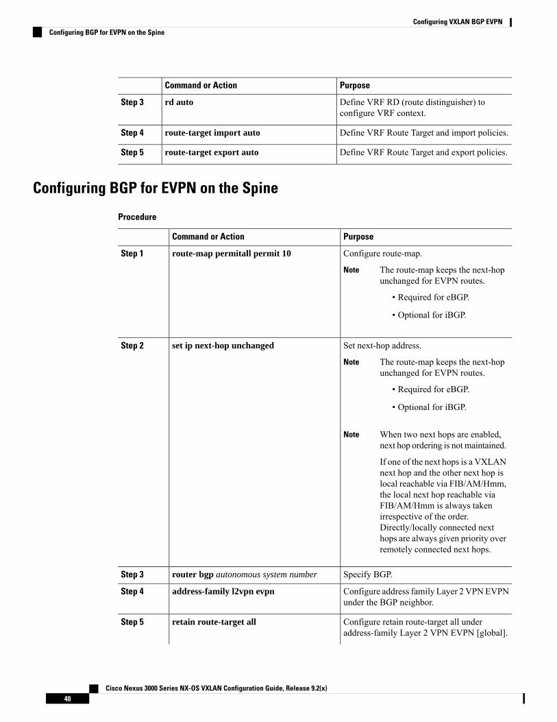
PurposeCommand or Action
Define VRF RD (route distinguisher) toconfigure VRF context.
rd autoStep 3
Define VRF Route Target and import policies.route-target import autoStep 4
Define VRF Route Target and export policies.route-target export autoStep 5
Configuring BGP for EVPN on the Spine
Procedure
PurposeCommand or Action
Configure route-map.route-map permitall permit 10Step 1
The route-map keeps the next-hopunchanged for EVPN routes.
• Required for eBGP.
• Optional for iBGP.
Note
Set next-hop address.set ip next-hop unchangedStep 2
The route-map keeps the next-hopunchanged for EVPN routes.
• Required for eBGP.
• Optional for iBGP.
Note
When two next hops are enabled,next hop ordering is not maintained.
If one of the next hops is a VXLANnext hop and the other next hop islocal reachable via FIB/AM/Hmm,the local next hop reachable viaFIB/AM/Hmm is always takenirrespective of the order.Directly/locally connected nexthops are always given priority overremotely connected next hops.
Note
Specify BGP.router bgp autonomous system numberStep 3
Configure address family Layer 2 VPNEVPNunder the BGP neighbor.
address-family l2vpn evpnStep 4
Configure retain route-target all underaddress-family Layer 2 VPN EVPN [global].
retain route-target allStep 5
Cisco Nexus 3000 Series NX-OS VXLAN Configuration Guide, Release 9.2(x)40
Configuring VXLAN BGP EVPNConfiguring BGP for EVPN on the Spine
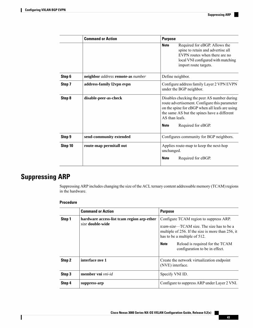
PurposeCommand or Action
Required for eBGP. Allows thespine to retain and advertise allEVPN routes when there are nolocal VNI configuredwithmatchingimport route targets.
Note
Define neighbor.neighbor address remote-as numberStep 6
Configure address family Layer 2 VPNEVPNunder the BGP neighbor.
address-family l2vpn evpnStep 7
Disables checking the peer AS number duringroute advertisement. Configure this parameter
disable-peer-as-checkStep 8
on the spine for eBGP when all leafs are usingthe same AS but the spines have a differentAS than leafs.
Required for eBGP.Note
Configures community for BGP neighbors.send-community extendedStep 9
Applies route-map to keep the next-hopunchanged.
route-map permitall outStep 10
Required for eBGP.Note
Suppressing ARPSuppressing ARP includes changing the size of the ACL ternary content addressable memory (TCAM) regionsin the hardware.
Procedure
PurposeCommand or Action
Configure TCAM region to suppress ARP.hardware access-list tcam region arp-ethersize double-wide
Step 1
tcam-size—TCAM size. The size has to be amultiple of 256. If the size is more than 256, ithas to be a multiple of 512.
Reload is required for the TCAMconfiguration to be in effect.
Note
Create the network virtualization endpoint(NVE) interface.
interface nve 1Step 2
Specify VNI ID.member vni vni-idStep 3
Configure to suppress ARP under Layer 2 VNI.suppress-arpStep 4
Cisco Nexus 3000 Series NX-OS VXLAN Configuration Guide, Release 9.2(x)41
Configuring VXLAN BGP EVPNSuppressing ARP
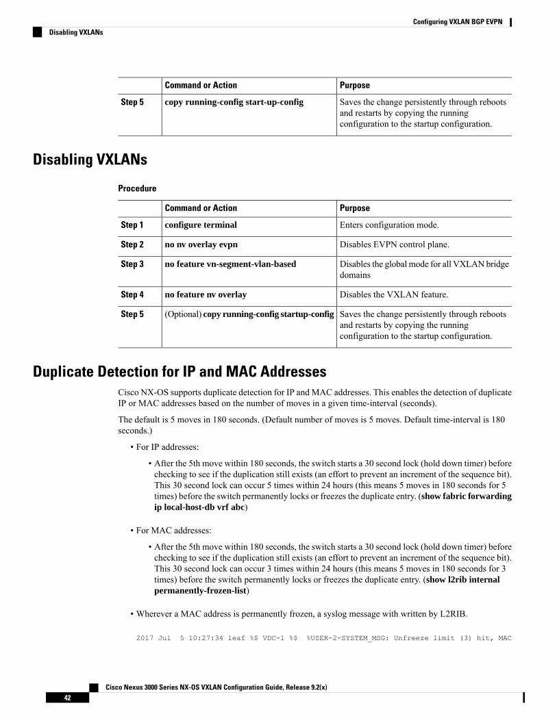
PurposeCommand or Action
Saves the change persistently through rebootsand restarts by copying the runningconfiguration to the startup configuration.
copy running-config start-up-configStep 5
Disabling VXLANs
Procedure
PurposeCommand or Action
Enters configuration mode.configure terminalStep 1
Disables EVPN control plane.no nv overlay evpnStep 2
Disables the global mode for all VXLANbridgedomains
no feature vn-segment-vlan-basedStep 3
Disables the VXLAN feature.no feature nv overlayStep 4
Saves the change persistently through rebootsand restarts by copying the runningconfiguration to the startup configuration.
(Optional) copy running-config startup-configStep 5
Duplicate Detection for IP and MAC AddressesCisco NX-OS supports duplicate detection for IP and MAC addresses. This enables the detection of duplicateIP or MAC addresses based on the number of moves in a given time-interval (seconds).
The default is 5 moves in 180 seconds. (Default number of moves is 5 moves. Default time-interval is 180seconds.)
• For IP addresses:
• After the 5th move within 180 seconds, the switch starts a 30 second lock (hold down timer) beforechecking to see if the duplication still exists (an effort to prevent an increment of the sequence bit).This 30 second lock can occur 5 times within 24 hours (this means 5 moves in 180 seconds for 5times) before the switch permanently locks or freezes the duplicate entry. (show fabric forwardingip local-host-db vrf abc)
• For MAC addresses:
• After the 5th move within 180 seconds, the switch starts a 30 second lock (hold down timer) beforechecking to see if the duplication still exists (an effort to prevent an increment of the sequence bit).This 30 second lock can occur 3 times within 24 hours (this means 5 moves in 180 seconds for 3times) before the switch permanently locks or freezes the duplicate entry. (show l2rib internalpermanently-frozen-list)
• Wherever a MAC address is permanently frozen, a syslog message with written by L2RIB.
2017 Jul 5 10:27:34 leaf %$ VDC-1 %$ %USER-2-SYSTEM_MSG: Unfreeze limit (3) hit, MAC
Cisco Nexus 3000 Series NX-OS VXLAN Configuration Guide, Release 9.2(x)42
Configuring VXLAN BGP EVPNDisabling VXLANs

0000.0033.3333in topo: 200 is permanently frozen - l2rib2017 Jul 5 10:27:34 leaf %$ VDC-1 %$ %USER-2-SYSTEM_MSG: Detected duplicate host0000.0033.3333, topology 200, during Local update, with host located at remote VTEP1.2.3.4, VNI 2 - l2rib2017 Jul 5 10:27:34 leaf %$ VDC-1 %$ %USER-2-SYSTEM_MSG: Unfreeze limit (3) hit, MAC0000.0033.3334in topo: 200 is permanently frozen - l2rib2017 Jul 5 10:27:34 leaf %$ VDC-1 %$ %USER-2-SYSTEM_MSG: Detected duplicate host0000.0033.3334, topology 200, during Local update, with host l
The following are example commands to help the configuration of the number of VM moves in a specifictime interval (seconds) for duplicate IP-detection:
DescriptionCommand
Available sub-commands:
• Anycast gateway MAC of theswitch.
• To detect duplicate host addressesin n seconds.
switch(config)# fabric forwarding ?anycast-gateway-macdup-host-ip-addr-detection
The number of host moves allowed in nseconds. The range is 1 to 1000 moves;default is 5 moves.
switch(config)# fabric forwardingdup-host-ip-addr-detection ?
<1-1000>
The duplicate detection timeout inseconds for the number of host moves.The range is 2 to 36000 seconds; defaultis 180 seconds.
switch(config)# fabric forwardingdup-host-ip-addr-detection 100 ?
<2-36000>
Detects duplicate host addresses (limitedto 100 moves) in a period of 10 seconds.switch(config)# fabric forwarding
dup-host-ip-addr-detection 100 10
The following are example commands to help the configuration of the number of VM moves in a specifictime interval (seconds) for duplicate MAC-detection:
DescriptionCommand
Available sub-commands for L2RIB:
• The number of host moves allowedin n seconds. The range is 1 to 1000moves.
• Default setting (5 moves in 180 inseconds).
switch(config)# l2rib dup-host-mac-detection ?<1-1000>default
The duplicate detection timeout inseconds for the number of host moves.The range is 2 to 36000 seconds; defaultis 180 seconds.
switch(config)# l2rib dup-host-mac-detection 100 ?<2-36000>
Cisco Nexus 3000 Series NX-OS VXLAN Configuration Guide, Release 9.2(x)43
Configuring VXLAN BGP EVPNDuplicate Detection for IP and MAC Addresses
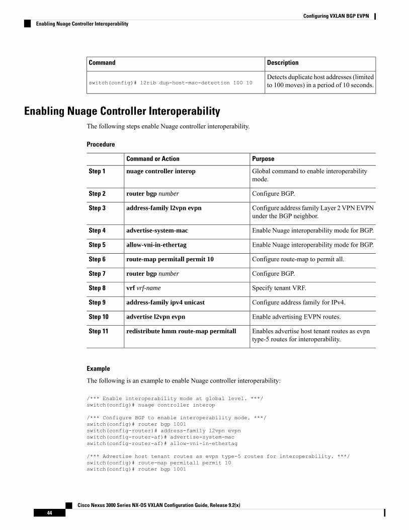
DescriptionCommand
Detects duplicate host addresses (limitedto 100 moves) in a period of 10 seconds.switch(config)# l2rib dup-host-mac-detection 100 10
Enabling Nuage Controller InteroperabilityThe following steps enable Nuage controller interoperability.
Procedure
PurposeCommand or Action
Global command to enable interoperabilitymode.
nuage controller interopStep 1
Configure BGP.router bgp numberStep 2
Configure address family Layer 2 VPNEVPNunder the BGP neighbor.
address-family l2vpn evpnStep 3
Enable Nuage interoperability mode for BGP.advertise-system-macStep 4
Enable Nuage interoperability mode for BGP.allow-vni-in-ethertagStep 5
Configure route-map to permit all.route-map permitall permit 10Step 6
Configure BGP.router bgp numberStep 7
Specify tenant VRF.vrf vrf-nameStep 8
Configure address family for IPv4.address-family ipv4 unicastStep 9
Enable advertising EVPN routes.advertise l2vpn evpnStep 10
Enables advertise host tenant routes as evpntype-5 routes for interoperability.
redistribute hmm route-map permitallStep 11
Example
The following is an example to enable Nuage controller interoperability:
/*** Enable interoperability mode at global level. ***/switch(config)# nuage controller interop
/*** Configure BGP to enable interoperability mode. ***/switch(config)# router bgp 1001switch(config-router)# address-family l2vpn evpnswitch(config-router-af)# advertise-system-macswitch(config-router-af)# allow-vni-in-ethertag
/*** Advertise host tenant routes as evpn type-5 routes for interoperability. ***/switch(config)# route-map permitall permit 10switch(config)# router bgp 1001
Cisco Nexus 3000 Series NX-OS VXLAN Configuration Guide, Release 9.2(x)44
Configuring VXLAN BGP EVPNEnabling Nuage Controller Interoperability

switch(config-router)# vrf vni-491830switch(config-router-vrf)# address-family ipv4 unicastswitch(config-router-vrf-af)# advertise l2vpn evpnswitch(config-router-vrf-af)# redistribute hmm route-map permitall
Verifying the VXLAN BGP EVPN ConfigurationTo display the VXLAN BGP EVPN configuration information, enter one of the following commands:
PurposeCommand
Displays VRFs and associated VNIsshow nve vrf
Displays routing table information.show bgp l2vpn evpn
Displays ARP suppression information.show ip arp suppression-cache [detail | summary| vlan vlan | statistics ]
Displays VXLAN interface status.show vxlan interface
Displays VXLAN VLAN logical port VP count.
A VP is allocated on a per-port per-VLANbasis. The sum of all VPs across allVXLAN-enabled Layer 2 ports gives thetotal logical port VP count. For example,if there are 10 Layer 2 trunk interfaces,each with 10 VXLAN VLANs, then thetotal VXLANVLAN logical port VP countis 10*10 = 100.
Note
show vxlan interface | count
Displays Layer 2 route information.show l2route evpn mac [all | evi evi [bgp | local |static | vxlan | arp]]
Displays all fl routes.show l2route evpn fl all
Displays all imet routes.show l2route evpn imet all
Displays all MAC IP routes.show l2route evpn mac-ip all
show l2route evpn mac-ip all detail
Displays Layer 2 route topology.show l2route topology
Although the show ip bgp command is available for verifying a BGP configuration, as a best practice, it ispreferable to use the show bgp command instead.
Note
Cisco Nexus 3000 Series NX-OS VXLAN Configuration Guide, Release 9.2(x)45
Configuring VXLAN BGP EVPNVerifying the VXLAN BGP EVPN Configuration

Example of VXLAN BGP EVPN (EBGP)An example of a VXLAN BGP EVPN (EBGP):
Figure 3: VXLAN BGP EVPN Topology (EBGP)
EBGP between Spine and Leaf
• Spine (9504-A)
• Enable the EVPN control planenv overlay evpn
• Enable the relevant protocols
feature bgpfeature pim
• Configure Loopback for local VTEP IP, and BGP
Cisco Nexus 3000 Series NX-OS VXLAN Configuration Guide, Release 9.2(x)46
Configuring VXLAN BGP EVPNExample of VXLAN BGP EVPN (EBGP)

interface loopback0ip address 10.1.1.1/32ip pim sparse-mode
• Configure Loopback for Anycast RP
interface loopback1ip address 100.1.1.1/32ip pim sparse-mode
• Configure Anycast RP
ip pim rp-address 100.1.1.1 group-list 225.0.0.0/8ip pim rp-candidate loopback1 group-list 225.0.0.0/8ip pim log-neighbor-changesip pim ssm range 232.0.0.0/8ip pim anycast-rp 100.1.1.1 10.1.1.1ip pim anycast-rp 100.1.1.1 20.1.1.1
• Configure route-map used by EBGP for Spine
route-map permitall permit 10set ip next-hop unchanged
• Configure interfaces for Spine-leaf interconnect
interface Ethernet4/2ip address 192.168.1.42/24ip pim sparse-modeno shutdown
interface Ethernet4/3ip address 192.168.2.43/24ip pim sparse-modeno shutdown
• Configure the BGP overlay for the EVPN address family.
router bgp 100router-id 10.1.1.1address-family l2vpn evpnnexthop route-map permitallretain route-target all
neighbor 30.1.1.1 remote-as 200update-source loopback0ebgp-multihop 3address-family l2vpn evpndisable-peer-as-checksend-community extendedroute-map permitall out
neighbor 40.1.1.1 remote-as 200update-source loopback0ebgp-multihop 3address-family l2vpn evpndisable-peer-as-checksend-community extendedroute-map permitall out
• Configure the BGP underlay.
Cisco Nexus 3000 Series NX-OS VXLAN Configuration Guide, Release 9.2(x)47
Configuring VXLAN BGP EVPNExample of VXLAN BGP EVPN (EBGP)

neighbor 192.168.1.43 remote-as 200address-family ipv4 unicastallowas-indisable-peer-as-check
• Spine (9504-B)
• Enable the EVPN control plane and the relevant protocols
feature telnetfeature nxapifeature bash-shellfeature scp-servernv overlay evpnfeature bgpfeature pimfeature lldp
• Configure Anycast RP
ip pim rp-address 100.1.1.1 group-list 225.0.0.0/8ip pim rp-candidate loopback1 group-list 225.0.0.0/8ip pim log-neighbor-changesip pim ssm range 232.0.0.0/8ip pim anycast-rp 100.1.1.1 10.1.1.1ip pim anycast-rp 100.1.1.1 20.1.1.1vlan 1-1002route-map permitall permit 10set ip next-hop unchanged
• Configure interfaces for Spine-leaf interconnect
interface Ethernet4/2ip address 192.168.4.42/24ip pim sparse-modeno shutdown
interface Ethernet4/3ip address 192.168.3.43/24ip pim sparse-modeno shutdown
• Configure Loopback for local VTEP IP, and BGP
interface loopback0ip address 20.1.1.1/32ip pim sparse-mode
• Configure Loopback for Anycast RP
interface loopback1ip address 100.1.1.1/32ip pim sparse-mode
• Configure the BGP overlay for the EVPN address family.
router bgp 100
Cisco Nexus 3000 Series NX-OS VXLAN Configuration Guide, Release 9.2(x)48
Configuring VXLAN BGP EVPNExample of VXLAN BGP EVPN (EBGP)

router-id 20.1.1.1address-family l2vpn evpnretain route-target all
neighbor 30.1.1.1 remote-as 200update-source loopback0ebgp-multihop 3address-family l2vpn evpndisable-peer-as-checksend-community extendedroute-map permitall out
neighbor 40.1.1.1 remote-as 200ebgp-multihop 3address-family l2vpn evpndisable-peer-as-checksend-community extendedroute-map permitall out
• Configure the BGP underlay.
neighbor 192.168.1.43 remote-as 200address-family ipv4 unicastallowas-indisable-peer-as-check
• Leaf (9396-A)
• Enable the EVPN control plane
nv overlay evpn
• Enable the relevant protocols
feature bgpfeature pimfeature interface-vlanfeature dhcp
• Configure DHCP relay for Tenant VRFs
service dhcpip dhcp relayip dhcp relay information optionip dhcp relay sub-option type ciscoip dhcp relay information option vpn
• Enable VXLAN with distributed anycast-gateway using BGP EVPN
feature vn-segment-vlan-basedfeature nv overlayfabric forwarding anycast-gateway-mac 0000.2222.3333
• Enable PIM RP
ip pim rp-address 100.1.1.1 group-list 225.0.0.0/8
• Configure Loopback for BGP
interface loopback0
Cisco Nexus 3000 Series NX-OS VXLAN Configuration Guide, Release 9.2(x)49
Configuring VXLAN BGP EVPNExample of VXLAN BGP EVPN (EBGP)

ip address 30.1.1.1/32ip pim sparse-mode
• Configure Loopback for local VTEP IP
interface loopback1ip address 50.1.1.1/32ip pim sparse-mode
• Configure interfaces for Spine-leaf interconnect
interface Ethernet2/2no switchportload-interval counter 1 5ip address 192.168.1.22/24ip pim sparse-modeno shutdown
interface Ethernet2/3no switchportload-interval counter 1 5ip address 192.168.3.23/24ip pim sparse-modeno shutdown
• Create the VRF overlay VLAN and configure the vn-segment.
vlan 101vn-segment 900001
• Configure VRF overlay VLAN/SVI for the VRFinterface Vlan101no shutdownvrf member vxlan-900001ip forward
• Create VLAN and provide mapping to VXLAN
vlan 1001vn-segment 2001001
vlan 1002vn-segment 2001002
• Create VRF and configure VNI
vrf context vxlan-900001vni 900001
The rd auto and route-target commands are automatically configured unlessone or more are entered as overrides.
Note
rd autoaddress-family ipv4 unicastroute-target import 65535:101 evpn
Cisco Nexus 3000 Series NX-OS VXLAN Configuration Guide, Release 9.2(x)50
Configuring VXLAN BGP EVPNExample of VXLAN BGP EVPN (EBGP)

route-target export 65535:101 evpnroute-target import 65535:101route-target export 65535:101
address-family ipv6 unicastroute-target import 65535:101 evpnroute-target export 65535:101 evpnroute-target import 65535:101route-target export 65535:101
• Create server facing SVI and enable distributed anycast-gateway
interface Vlan1001no shutdownvrf member vxlan-900001ip address 4.1.1.1/24ipv6 address 4:1:0:1::1/64fabric forwarding mode anycast-gatewayip dhcp relay address 192.168.100.1 use-vrf default
interface Vlan1002no shutdownvrf member vxlan-900001ip address 4.2.2.1/24ipv6 address 4:2:0:1::1/64fabric forwarding mode anycast-gateway
• Configure ACL TCAM region for ARP suppression
hardware access-list tcam region arp-ether 256 double-wide
•
You can choose either of the following two options for creating the NVE interface.Use the first option for a small number of VNIs. Use the second option toconfigure a large number of VNIs.
Note
Create the network virtualization endpoint (NVE) interface
Option 1
interface nve1no shutdownsource-interface loopback1host-reachability protocol bgpmember vni 900001 associate-vrfmember vni 2001001suppress-arpmcast-group 225.4.0.1
member vni 2001002suppress-arpmcast-group 225.4.0.1
Option 2interface nve1no shutdownsource-interface loopback 1host-reachibility protocol bgpglobal suppress-arp
Cisco Nexus 3000 Series NX-OS VXLAN Configuration Guide, Release 9.2(x)51
Configuring VXLAN BGP EVPNExample of VXLAN BGP EVPN (EBGP)
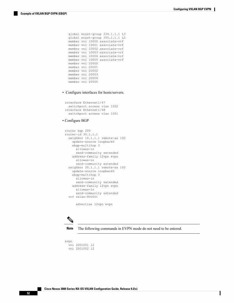
global mcast-group 224.1.1.1 L3global mcast-group 255.1.1.1 L2member vni 10000 associate-vrfmember vni 10001 associate-vrfmember vni 10002 associate-vrfmember vni 10003 associate-vrfmember vni 10004 associate-vrfmember vni 10005 associate-vrfmember vni 20000member vni 20001member vni 20002member vni 20003member vni 20004member vni 20005
• Configure interfaces for hosts/servers.
interface Ethernet1/47switchport access vlan 1002
interface Ethernet1/48switchport access vlan 1001
• Configure BGP
router bgp 200router-id 30.1.1.1neighbor 10.1.1.1 remote-as 100update-source loopback0ebgp-multihop 3allowas-insend-community extended
address-family l2vpn evpnallowas-insend-community extended
neighbor 20.1.1.1 remote-as 100update-source loopback0ebgp-multihop 3allowas-insend-community extended
address-family l2vpn evpnallowas-insend-community extended
vrf vxlan-900001
advertise l2vpn evpn
The following commands in EVPN mode do not need to be entered.Note
evpnvni 2001001 l2vni 2001002 l2
Cisco Nexus 3000 Series NX-OS VXLAN Configuration Guide, Release 9.2(x)52
Configuring VXLAN BGP EVPNExample of VXLAN BGP EVPN (EBGP)
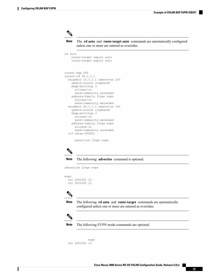
The rd auto and route-target auto commands are automatically configuredunless one or more are entered as overrides.
Note
rd autoroute-target import autoroute-target export auto
router bgp 200router-id 30.1.1.1neighbor 10.1.1.1 remote-as 100update-source loopback0ebgp-multihop 3allowas-insend-community extended
address-family l2vpn evpnallowas-insend-community extended
neighbor 20.1.1.1 remote-as 100update-source loopback0ebgp-multihop 3allowas-insend-community extended
address-family l2vpn evpnallowas-insend-community extended
vrf vxlan-900001
advertise l2vpn evpn
The following advertise command is optional.Note
advertise l2vpn evpn
evpnvni 2001001 l2vni 2001002 l2
The following rd auto and route-target commands are automaticallyconfigured unless one or more are entered as overrides.
Note
The following EVPN mode commands are optional.Note
evpnvni 2001001 l2
Cisco Nexus 3000 Series NX-OS VXLAN Configuration Guide, Release 9.2(x)53
Configuring VXLAN BGP EVPNExample of VXLAN BGP EVPN (EBGP)

rd autoroute-target import autoroute-target export auto
vni 2001002 l2rd autoroute-target import autoroute-target export auto
• Leaf (9396-B)
• Enable the EVPN control plane functionality and the relevant protocols
feature telnetfeature nxapifeature bash-shellfeature scp-servernv overlay evpnfeature bgpfeature pimfeature interface-vlanfeature vn-segment-vlan-basedfeature lldpfeature nv overlay
• Enable VxLAN with distributed anycast-gateway using BGP EVPN
fabric forwarding anycast-gateway-mac 0000.2222.3333
• Create the VRF overlay VLAN and configure the vn-segment
vlan 1-1002vlan 101vn-segment 900001
• Create VLAN and provide mapping to VXLAN
vlan 1001vn-segment 2001001
vlan 1002vn-segment 2001002
• Create VRF and configure VNI
vrf context vxlan-900001vni 900001
The following commands are automatically configured unless one or more areentered as overrides.
Note
rd autoaddress-family ipv4 unicastroute-target import 65535:101 evpnroute-target export 65535:101 evpnroute-target import 65535:101route-target export 65535:101
Cisco Nexus 3000 Series NX-OS VXLAN Configuration Guide, Release 9.2(x)54
Configuring VXLAN BGP EVPNExample of VXLAN BGP EVPN (EBGP)

address-family ipv6 unicastroute-target import 65535:101 evpnroute-target export 65535:101 evpnroute-target import 65535:101 evpnroute-target export 65535:101 evpn
• Configure ACL TCAM region for ARP suppression
hardware access-list tcam region arp-ether 256 double-wide
• Configure internal control VLAN/SVI for the VRF
interface Vlan1
interface Vlan101no shutdownvrf member vxlan-900001
• Create server facing SVI and enable distributed anycast-gateway
interface Vlan1001no shutdownvrf member vxlan-900001ip address 4.1.1.1/24ipv6 address 4:1:0:1::1/64fabric forwarding mode anycast-gateway
interface Vlan1002no shutdownvrf member vxlan-900001ip address 4.2.2.1/24ipv6 address 4:2:0:1::1/64fabric forwarding mode anycast-gateway
• Create the network virtualization endpoint (NVE) interface
You can choose either of the following two procedures for creating the NVEinterface. Use Option 1 for a small number of VNIs. Use Option 2 to configurea large number of VNIs.
Note
Option 1interface nve1no shutdownsource-interface loopback1host-reachability protocol bgpmember vni 10000 associate-vrfmcast-group 224.1.1.1member vni 10001 associate-vrfmcast-group 224.1.1.1member vni20000suppress-arpmcast-group 225.1.1.1member vni 20001suppress-arpmcast-group 225.1.1.1
Cisco Nexus 3000 Series NX-OS VXLAN Configuration Guide, Release 9.2(x)55
Configuring VXLAN BGP EVPNExample of VXLAN BGP EVPN (EBGP)

Option 2interface nve1no shutdownsource-interface loopback 1host-reachibility protocol bgpglobal suppress-arpglobal mcast-group 224.1.1.1 L3global mcast-group 255.1.1.1 L2member vni 10000 associate-vrfmember vni 10001 associate-vrfmember vni 10002 associate-vrfmember vni 10003 associate-vrfmember vni 10004 associate-vrfmember vni 10005 associate-vrfmember vni 20000member vni 20001member vni 20002member vni 20003member vni 20004member vni 20005
• Configure interfaces for hosts/servers
interface Ethernet1/47switchport access vlan 1002
interface Ethernet1/48switchport access vlan 1001
• Configure interfaces for Spine-leaf interconnect
interface Ethernet2/1
interface Ethernet2/2no switchportload-interval counter 1 5ip address 192.168.4.22/24ip pim sparse-modeno shutdown
interface Ethernet2/3no switchportload-interval counter 1 5ip address 192.168.2.23/24ip pim sparse-modeno shutdown
• Configure Loopback for BGP
interface loopback0ip address 40.1.1.1/32ip pim sparse-mode
• Configure Loopback for local VTEP IP
interface loopback1ip address 51.1.1.1/32ip pim sparse-mode
Cisco Nexus 3000 Series NX-OS VXLAN Configuration Guide, Release 9.2(x)56
Configuring VXLAN BGP EVPNExample of VXLAN BGP EVPN (EBGP)
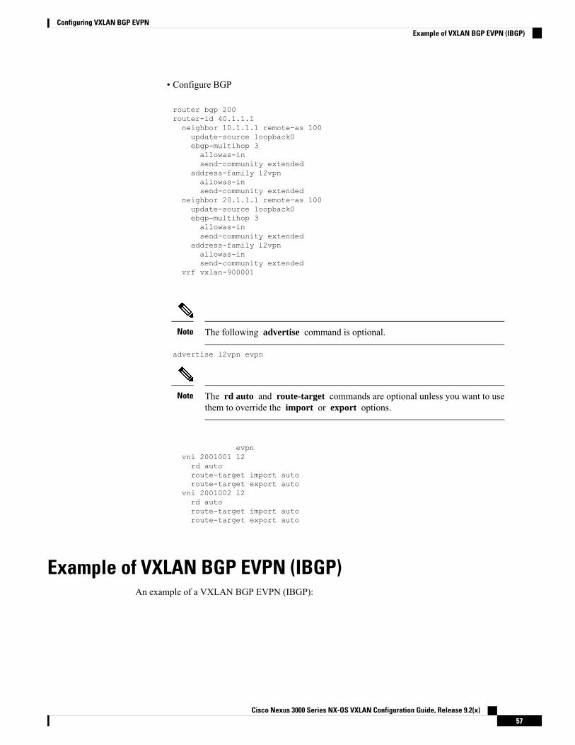
• Configure BGP
router bgp 200router-id 40.1.1.1neighbor 10.1.1.1 remote-as 100update-source loopback0ebgp-multihop 3allowas-insend-community extended
address-family l2vpnallowas-insend-community extended
neighbor 20.1.1.1 remote-as 100update-source loopback0ebgp-multihop 3allowas-insend-community extended
address-family l2vpnallowas-insend-community extended
vrf vxlan-900001
The following advertise command is optional.Note
advertise l2vpn evpn
The rd auto and route-target commands are optional unless you want to usethem to override the import or export options.
Note
evpnvni 2001001 l2rd autoroute-target import autoroute-target export auto
vni 2001002 l2rd autoroute-target import autoroute-target export auto
Example of VXLAN BGP EVPN (IBGP)An example of a VXLAN BGP EVPN (IBGP):
Cisco Nexus 3000 Series NX-OS VXLAN Configuration Guide, Release 9.2(x)57
Configuring VXLAN BGP EVPNExample of VXLAN BGP EVPN (IBGP)
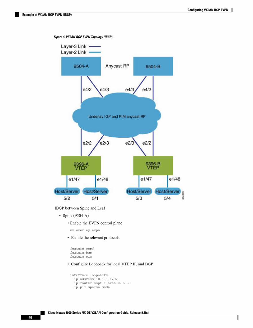
Figure 4: VXLAN BGP EVPN Topology (IBGP)
IBGP between Spine and Leaf
• Spine (9504-A)
• Enable the EVPN control planenv overlay evpn
• Enable the relevant protocols
feature ospffeature bgpfeature pim
• Configure Loopback for local VTEP IP, and BGP
interface loopback0ip address 10.1.1.1/32ip router ospf 1 area 0.0.0.0ip pim sparse-mode
Cisco Nexus 3000 Series NX-OS VXLAN Configuration Guide, Release 9.2(x)58
Configuring VXLAN BGP EVPNExample of VXLAN BGP EVPN (IBGP)

• Configure Loopback for Anycast RP
interface loopback1ip address 100.1.1.1/32ip router ospf 1 area 0.0.0.0ip pim sparse-mode
• Configure Anycast RP
ip pim rp-address 100.1.1.1 group-list 225.0.0.0/8ip pim rp-candidate loopback1 group-list 225.0.0.0/8ip pim ssm range 232.0.0.0/8ip pim anycast-rp 100.1.1.1 10.1.1.1ip pim anycast-rp 100.1.1.1 20.1.1.1
• Enable OSPF for underlay routing
router ospf 1
• Configure interfaces for Spine-leaf interconnect
interface Ethernet4/2ip address 192.168.1.42/24ip router ospf 1 area 0.0.0.0ip pim sparse-modeno shutdown
interface Ethernet4/3ip address 192.168.2.43/24ip router ospf 1 area 0.0.0.0ip pim sparse-modeno shutdown
• Configure BGP
router bgp 65535router-id 10.1.1.1neighbor 30.1.1.1 remote-as 65535update-source loopback0address-family l2vpn evpnsend-community bothroute-reflector-client
neighbor 40.1.1.1 remote-as 65535update-source loopback0address-family l2vpn evpnsend-community bothroute-reflector-client
• Spine (9504-B)
• Enable the EVPN control plane and the relevant protocols
feature telnetfeature nxapifeature bash-shellfeature scp-servernv overlay evpnfeature ospffeature bgp
Cisco Nexus 3000 Series NX-OS VXLAN Configuration Guide, Release 9.2(x)59
Configuring VXLAN BGP EVPNExample of VXLAN BGP EVPN (IBGP)

feature pimfeature lldp
• Configure Anycast RP
ip pim rp-address 100.1.1.1 group-list 225.0.0.0/8ip pim rp-candidate loopback1 group-list 225.0.0.0/8ip pim ssm range 232.0.0.0/8ip pim anycast-rp 100.1.1.1 10.1.1.1ip pim anycast-rp 100.1.1.1 20.1.1.1vlan 1-1002
• Configure interfaces for Spine-leaf interconnect
interface Ethernet4/2ip address 192.168.4.42/24ip router ospf 1 area 0.0.0.0ip pim sparse-modeno shutdown
interface Ethernet4/3ip address 192.168.3.43/24ip router ospf 1 area 0.0.0.0ip pim sparse-modeno shutdown
• Configure Loopback for local VTEP IP, and BGP
interface loopback0ip address 20.1.1.1/32ip router ospf 1 area 0.0.0.0ip pim sparse-mode
• Configure Loopback for Anycast RP
interface loopback1ip address 100.1.1.1/32ip router ospf 1 area 0.0.0.0ip pim sparse-mode
• Enable OSPF for underlay routing
router ospf 1
• Configure BGP
router bgp 65535router-id 20.1.1.1neighbor 30.1.1.1 remote-as 65535update-source loopback0address-family l2vpn evpnsend-community bothroute-reflector-client
neighbor 40.1.1.1 remote-as 65535update-source loopback0address-family l2vpn evpnsend-community bothroute-reflector-client
Cisco Nexus 3000 Series NX-OS VXLAN Configuration Guide, Release 9.2(x)60
Configuring VXLAN BGP EVPNExample of VXLAN BGP EVPN (IBGP)
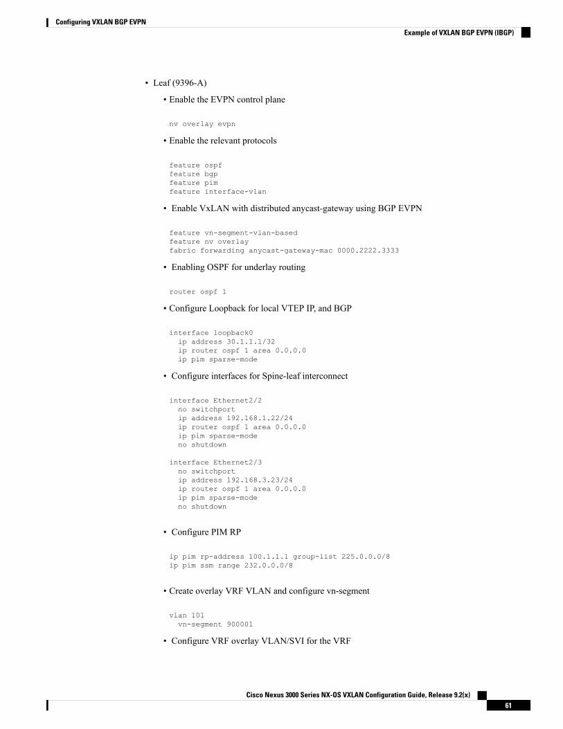
• Leaf (9396-A)
• Enable the EVPN control plane
nv overlay evpn
• Enable the relevant protocols
feature ospffeature bgpfeature pimfeature interface-vlan
• Enable VxLAN with distributed anycast-gateway using BGP EVPN
feature vn-segment-vlan-basedfeature nv overlayfabric forwarding anycast-gateway-mac 0000.2222.3333
• Enabling OSPF for underlay routing
router ospf 1
• Configure Loopback for local VTEP IP, and BGP
interface loopback0ip address 30.1.1.1/32ip router ospf 1 area 0.0.0.0ip pim sparse-mode
• Configure interfaces for Spine-leaf interconnect
interface Ethernet2/2no switchportip address 192.168.1.22/24ip router ospf 1 area 0.0.0.0ip pim sparse-modeno shutdown
interface Ethernet2/3no switchportip address 192.168.3.23/24ip router ospf 1 area 0.0.0.0ip pim sparse-modeno shutdown
• Configure PIM RP
ip pim rp-address 100.1.1.1 group-list 225.0.0.0/8ip pim ssm range 232.0.0.0/8
• Create overlay VRF VLAN and configure vn-segment
vlan 101vn-segment 900001
• Configure VRF overlay VLAN/SVI for the VRF
Cisco Nexus 3000 Series NX-OS VXLAN Configuration Guide, Release 9.2(x)61
Configuring VXLAN BGP EVPNExample of VXLAN BGP EVPN (IBGP)

interface Vlan101no shutdownvrf member vxlan-900001
• Create VLAN and provide mapping to VXLAN
vlan 1001vn-segment 2001001
vlan 1002vn-segment 2001002
• Create VRF and configure VNI
vrf context vxlan-900001vni 900001
The rd auto and route-target commands are automatically configured unlessone or more are entered as overrides.
Note
rd autoaddress-family ipv4 unicastroute-target both autoroute-target both auto evpn
address-family ipv6 unicastroute-target both autoroute-target both auto evpn
• Create server facing SVI and enable distributed anycast-gateway
interface Vlan1001no shutdownvrf member vxlan-900001ip address 4.1.1.1/24ipv6 address 4:1:0:1::1/64fabric forwarding mode anycast-gateway
interface Vlan1002no shutdownvrf member vxlan-900001ip address 4.2.2.1/24ipv6 address 4:2:0:1::1/64fabric forwarding mode anycast-gateway
• Configure ACL TCAM region for ARP suppression
hardware access-list tcam region arp-ether 256 double-wide
•
You can choose either of the following two procedures for creating the NVEinterfaces. Use the first one for a small number of VNIs. Use the second procedureto configure a large number of VNIs.
Note
Cisco Nexus 3000 Series NX-OS VXLAN Configuration Guide, Release 9.2(x)62
Configuring VXLAN BGP EVPNExample of VXLAN BGP EVPN (IBGP)

Create the network virtualization endpoint (NVE) interface
Option 1
interface nve1no shutdownsource-interface loopback0host-reachability protocol bgpmember vni 900001 associate-vrfmember vni 2001001suppress-arpmcast-group 225.4.0.1
member vni 2001002suppress-arpmcast-group 225.4.0.1
Option 2Interface nve1source-interface loopback 1host-reachability protocol bgpglobal suppress-arpglobal mcast-group 255.1.1.1 L2global mcast-group 255.1.1.2 L3member vni 10000member vni 20000member vni 30000
• Configure interfaces for hosts/servers
interface Ethernet1/47switchport access vlan 1002
interface Ethernet1/48switchport access vlan 1001
• Configure BGP
router bgp 65535router-id 30.1.1.1neighbor 10.1.1.1 remote-as 65535update-source loopback0address-family l2vpn evpnsend-community both
neighbor 20.1.1.1 remote-as 65535update-source loopback0address-family l2vpn evpnsend-community both
vrf vxlan-900001address-family ipv4 unicastadvertise l2vpn evpn
The following commands in EVPN mode do not need to be entered.Note
Cisco Nexus 3000 Series NX-OS VXLAN Configuration Guide, Release 9.2(x)63
Configuring VXLAN BGP EVPNExample of VXLAN BGP EVPN (IBGP)
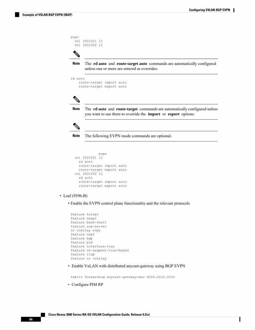
evpnvni 2001001 l2vni 2001002 l2
The rd auto and route-target auto commands are automatically configuredunless one or more are entered as overrides.
Note
rd autoroute-target import autoroute-target export auto
The rd auto and route-target commands are automatically configured unlessyou want to use them to override the import or export options.
Note
The following EVPN mode commands are optional.Note
evpnvni 2001001 l2rd autoroute-target import autoroute-target export auto
vni 2001002 l2rd autoroute-target import autoroute-target export auto
• Leaf (9396-B)
• Enable the EVPN control plane functionality and the relevant protocols
feature telnetfeature nxapifeature bash-shellfeature scp-servernv overlay evpnfeature ospffeature bgpfeature pimfeature interface-vlanfeature vn-segment-vlan-basedfeature lldpfeature nv overlay
• Enable VxLAN with distributed anycast-gateway using BGP EVPN
fabric forwarding anycast-gateway-mac 0000.2222.3333
• Configure PIM RP
Cisco Nexus 3000 Series NX-OS VXLAN Configuration Guide, Release 9.2(x)64
Configuring VXLAN BGP EVPNExample of VXLAN BGP EVPN (IBGP)

ip pim rp-address 100.1.1.1 group-list 225.0.0.0/8ip pim ssm range 232.0.0.0/8
• Create overlay VRF VLAN and configure vn-segment
vlan 1-1002vlan 101vn-segment 900001
• Create VLAN and provide mapping to VXLAN
vlan 1001vn-segment 2001001
vlan 1002vn-segment 2001002
• Create VRF and configure VNI
vrf context vxlan-900001vni 900001
The rd auto and route-target commands are automatically configured unlessyou want to use them to override the import or export options.
Note
rd autoaddress-family ipv4 unicastroute-target both autoroute-target both auto evpn
address-family ipv6 unicastroute-target both autoroute-target both auto evpn
• Configure ACL TCAM region for ARP suppression
hardware access-list tcam region arp-ether 256 double-wide
• Configure internal control VLAN/SVI for the VRF
interface Vlan101no shutdownvrf member vxlan-900001
• Create server facing SVI and enable distributed anycast-gateway
interface Vlan1001no shutdownvrf member vxlan-900001ip address 4.1.1.1/24ipv6 address 4:1:0:1::1/64fabric forwarding mode anycast-gateway
interface Vlan1002no shutdownvrf member vxlan-900001
Cisco Nexus 3000 Series NX-OS VXLAN Configuration Guide, Release 9.2(x)65
Configuring VXLAN BGP EVPNExample of VXLAN BGP EVPN (IBGP)
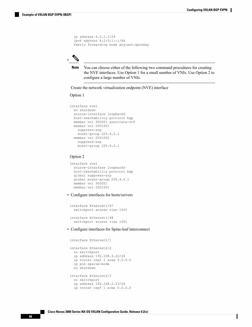
ip address 4.2.2.1/24ipv6 address 4:2:0:1::1/64fabric forwarding mode anycast-gateway
•
You can choose either of the following two command procedures for creatingthe NVE interfaces. Use Option 1 for a small number of VNIs. Use Option 2 toconfigure a large number of VNIs.
Note
Create the network virtualization endpoint (NVE) interface
Option 1
interface nve1no shutdownsource-interface loopback0host-reachability protocol bgpmember vni 900001 associate-vrfmember vni 2001001suppress-arpmcast-group 225.4.0.1
member vni 2001002suppress-arpmcast-group 225.4.0.1
Option 2Interface nve1source-interface loopback0host-reachability protocol bgpglobal suppress-arpglobal mcast-group 255.4.0.1member vni 900001member vni 2001001
• Configure interfaces for hosts/servers
interface Ethernet1/47switchport access vlan 1002
interface Ethernet1/48switchport access vlan 1001
• Configure interfaces for Spine-leaf interconnect
interface Ethernet2/1
interface Ethernet2/2no switchportip address 192.168.4.22/24ip router ospf 1 area 0.0.0.0ip pim sparse-modeno shutdown
interface Ethernet2/3no switchportip address 192.168.2.23/24ip router ospf 1 area 0.0.0.0
Cisco Nexus 3000 Series NX-OS VXLAN Configuration Guide, Release 9.2(x)66
Configuring VXLAN BGP EVPNExample of VXLAN BGP EVPN (IBGP)

ip pim sparse-modeno shutdown
• Configure Loopback for local VTEP IP, and BGP
interface loopback0ip address 40.1.1.1/32ip router ospf 1 area 0.0.0.0ip pim sparse-mode
• Enabling OSPF for underlay routing
router ospf 1
• Configure BGP
router bgp 65535router-id 40.1.1.1neighbor 10.1.1.1 remote-as 65535update-source loopback0address-family l2vpn evpnsend-community both
neighbor 20.1.1.1 remote-as 65535update-source loopback0address-family l2vpn evpnsend-community both
vrf vxlan-900001address-family ipv4 unicastadvertise l2vpn evpn
evpnvni 2001001 l2rd autoroute-target import autoroute-target export auto
vni 2001002 l2rd autoroute-target import autoroute-target export auto
The rd auto and route-target commands are optional unless you want to usethem to override the import or export options.
Note
evpnvni 2001001 l2rd autoroute-target import autoroute-target export auto
vni 2001002 l2rd autoroute-target import autoroute-target export auto
Cisco Nexus 3000 Series NX-OS VXLAN Configuration Guide, Release 9.2(x)67
Configuring VXLAN BGP EVPNExample of VXLAN BGP EVPN (IBGP)
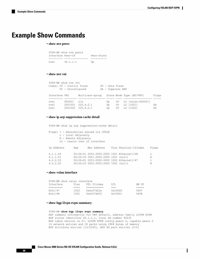
Example Show Commands• show nve peers
9396-B# show nve peersInterface Peer-IP Peer-State--------- --------------- ----------nve1 30.1.1.1 Up
• show nve vni
9396-B# show nve vniCodes: CP - Control Plane DP - Data Plane
UC - Unconfigured SA - Suppress ARP
Interface VNI Multicast-group State Mode Type [BD/VRF] Flags--------- -------- ----------------- ----- ---- ------------------ -----nve1 900001 n/a Up CP L3 [vxlan-900001]nve1 2001001 225.4.0.1 Up CP L2 [1001] SAnve1 2001002 225.4.0.1 Up CP L2 [1002] SA
• show ip arp suppression-cache detail
9396-B# show ip arp suppression-cache detail
Flags: + - Adjacencies synced via CFSoEL - Local AdjacencyR - Remote AdjacencyL2 - Learnt over L2 interface
Ip Address Age Mac Address Vlan Physical-ifindex Flags
4.1.1.54 00:06:41 0054.0000.0000 1001 Ethernet1/48 L4.1.1.51 00:20:33 0051.0000.0000 1001 (null) R4.2.2.53 00:06:41 0053.0000.0000 1002 Ethernet1/47 L4.2.2.52 00:20:33 0052.0000.0000 1002 (null) R
• show vxlan interface
9396-B# show vxlan interfaceInterface Vlan VPL Ifindex LTL HW VP========= ==== =========== === =====Eth1/47 1002 0x4c07d22e 0x10000 5697Eth1/48 1001 0x4c07d02f 0x10001 5698
• show bgp l2vpn evpn summary
9396-B# show bgp l2vpn evpn summaryBGP summary information for VRF default, address family L2VPN EVPNBGP router identifier 40.1.1.1, local AS number 65535BGP table version is 27, L2VPN EVPN config peers 2, capable peers 214 network entries and 18 paths using 2984 bytes of memoryBGP attribute entries [14/2240], BGP AS path entries [0/0]
Cisco Nexus 3000 Series NX-OS VXLAN Configuration Guide, Release 9.2(x)68
Configuring VXLAN BGP EVPNExample Show Commands

BGP community entries [0/0], BGP clusterlist entries [2/8]
Neighbor V AS MsgRcvd MsgSent TblVer InQ OutQ Up/Down State/PfxRcd10.1.1.1 4 65535 30199 30194 27 0 0 2w6d 420.1.1.1 4 65535 30199 30194 27 0 0 2w6d 4
• show bgp l2vpn evpn
9396-B# show bgp l2vpn evpnBGP routing table information for VRF default, address family L2VPN EVPNBGP table version is 27, Local Router ID is 40.1.1.1Status: s-suppressed, x-deleted, S-stale, d-dampened, h-history, *-valid, >-bestPath type: i-internal, e-external, c-confed, l-local, a-aggregate, r-redist, I-injectedOrigin codes: i - IGP, e - EGP, ? - incomplete, | - multipath, & - backup
Network Next Hop Metric LocPrf Weight PathRoute Distinguisher: 30.1.1.1:33768*>i[2]:[0]:[0]:[48]:[d8b1.9071.e903]:[0]:[0.0.0.0]/216
30.1.1.1 100 0 i* i 30.1.1.1 100 0 i*>i[2]:[0]:[0]:[48]:[d8b1.9071.e903]:[32]:[4.1.1.12]/272
30.1.1.1 100 0 i* i 30.1.1.1 100 0 i
Route Distinguisher: 30.1.1.1:33769*>i[2]:[0]:[0]:[48]:[d8b1.9071.e903]:[0]:[0.0.0.0]/216
30.1.1.1 100 0 i* i 30.1.1.1 100 0 i*>i[2]:[0]:[0]:[48]:[d8b1.9071.e903]:[32]:[4.2.2.11]/272
30.1.1.1 100 0 i* i 30.1.1.1 100 0 i
Route Distinguisher: 40.1.1.1:33768 (L2VNI 2001001)*>i[2]:[0]:[0]:[48]:[d8b1.9071.e903]:[0]:[0.0.0.0]/216
30.1.1.1 100 0 i*>l[2]:[0]:[0]:[48]:[f8c2.8890.2a45]:[0]:[0.0.0.0]/216
40.1.1.1 100 32768 i*>i[2]:[0]:[0]:[48]:[d8b1.9071.e903]:[32]:[4.1.1.12]/272
30.1.1.1 100 0 i*>l[2]:[0]:[0]:[48]:[f8c2.8890.2a45]:[32]:[4.1.1.122]/272
40.1.1.1 100 32768 i
Route Distinguisher: 40.1.1.1:33769 (L2VNI 2001002)*>i[2]:[0]:[0]:[48]:[d8b1.9071.e903]:[0]:[0.0.0.0]/216
30.1.1.1 100 0 i*>l[2]:[0]:[0]:[48]:[f8c2.8890.2a45]:[0]:[0.0.0.0]/216
40.1.1.1 100 32768 i*>i[2]:[0]:[0]:[48]:[d8b1.9071.e903]:[32]:[4.2.2.11]/272
30.1.1.1 100 0 i*>l[2]:[0]:[0]:[48]:[f8c2.8890.2a45]:[32]:[4.2.2.111]/272
40.1.1.1 100 32768 i
Route Distinguisher: 40.1.1.1:3 (L3VNI 900001)*>i[2]:[0]:[0]:[48]:[d8b1.9071.e903]:[32]:[4.1.1.12]/272
30.1.1.1 100 0 i*>i[2]:[0]:[0]:[48]:[d8b1.9071.e903]:[32]:[4.2.2.11]/272
30.1.1.1 100 0 i
• show l2route evpn mac all
9396-B# show l2route evpn mac all
Cisco Nexus 3000 Series NX-OS VXLAN Configuration Guide, Release 9.2(x)69
Configuring VXLAN BGP EVPNExample Show Commands

Flags -(Rmac):Router MAC (Stt):Static (L):Local (R):Remote (V):vPC link(Dup):Duplicate (Spl):Split (Rcv):Recv (AD):Auto-Delete (D):Del Pending(S):Stale (C):Clear, (Ps):Peer Sync (O):Re-Originated (Nho):NH-Override(Pf):Permanently-Frozen
Topology Mac Address Prod Flags Seq No Next-Hops----------- -------------- ------ ------------- ---------- ----------------101 6412.2574.9f27 VXLAN Rmac 0 30.1.1.11001 d8b1.9071.e903 BGP SplRcv 0 30.1.1.11001 f8c2.8890.2a45 Local L, 0 Eth1/481002 d8b1.9071.e903 BGP SplRcv 0 30.1.1.11002 f8c2.8890.2a45 Local L, 0 Eth1/47
• show l2route evpn mac-ip all
9396-B# show l2route evpn mac-ip allFlags -(Rmac):Router MAC (Stt):Static (L):Local (R):Remote (V):vPC link(Dup):Duplicate (Spl):Split (Rcv):Recv(D):Del Pending (S):Stale (C):Clear(Ps):Peer Sync (Ro):Re-OriginatedTopology Mac Address Prod Flags Seq No Host IP Next-Hops----------- -------------- ------ ---------- --------------- ---------------1001 d8b1.9071.e903 BGP -- 0 4.1.1.12 30.1.1.11001 f8c2.8890.2a45 HMM -- 0 4.1.1.122 Local1002 d8b1.9071.e903 BGP -- 0 4.2.2.11 30.1.1.11002 f8c2.8890.2a45 HMM -- 0 4.2.2.111 Local
VXLAN Cross Connect
About VXLAN Cross ConnectThis feature provides point-to-point tunneling of data and control packet from one VTEP to another. Everyattachment circuit will be part of a unique provider VNI. BGP EVPN signaling will discover these end-pointsbased on how the provider VNI is stretched in the fabric. All inner customer .1q tags will be preserved, as is,and packets will be encapsulated in the provider VNI at the encapsulation VTEP. On the decapsulationend-point, the provider VNI will forward the packet to its attachment circuit while preserving all customer.1q tags in the packets.
Cross Connect and xconnect are synonymous.Note
VXLAN Cross Connect enables VXLAN point-to-point functionality on the following switches:
• Cisco Nexus 9332PQ
• Cisco Nexus 9336C-FX2
• Cisco Nexus 9372PX
• Cisco Nexus 9372PX-E
• Cisco Nexus 9372TX
• Cisco Nexus 9372TX-E
Cisco Nexus 3000 Series NX-OS VXLAN Configuration Guide, Release 9.2(x)70
Configuring VXLAN BGP EVPNVXLAN Cross Connect

• Cisco Nexus 93120TX
• Cisco Nexus 93108TC-EX
• Cisco Nexus 93108TC-FX
• Cisco Nexus 93180LC-EX
• Cisco Nexus 93180YC-EX
• Cisco Nexus 93180YC-FX
• Cisco Nexus 93240YC-FX2
VXLAN Cross Connect enables tunneling of all control frames (CDP, LLDP, LACP, STP, BFD, and PAGP)and data across the VXLAN cloud.
Guidelines and Limitations for VXLAN Cross ConnectVXLAN Cross Connect has the following guidelines and limitations:
• When an upgrade is performed non-disruptively fromCiscoNX-OSRelease 7.0(3)I7(4) to CiscoNX-OSRelease 9.2(x) code, and if a VLAN is created and configured as xconnect, you must enter the copyrunning-config startup-config command and reload the switch. If the box was upgraded disruptivelyto Cisco NX-OS Release 9.2(x) code, a reload is not needed on configuring a VLAN as xconnect.
• MAC learning will be disabled on the xconnect VNIs and none of the host MAC will be learned on thetunnel access ports.
• Only supported on a BGP EVPN topology.
• LACP bundling of attachment circuits is not supported.
• Only one attachment circuit can be configured for a provider VNI on a given VTEP.
• A VNI can only be stretched in a point-to-point fashion. Point-to-multipoint is not supported.
• SVI on an xconnect VLAN is not supported.
• ARP suppression is not supported on an xconnect VLAN VNI.
• Xconnect is not supported on the following switches:
• Cisco Nexus 9504
• Cisco Nexus 9508
• Cisco Nexus 9516
• Scale of xconnect VLANs depends on the number of ports available on the switch. Every xconnect VLANcan tunnel all 4k customer VLANs.
• Xconnect or Crossconnect feature on vpc-vtep needs backup-svi as native VLAN on the vPC peer-link.
• Make sure that the NGOAM xconnect hb-interval is set to 5000 milliseconds on all VTEPs beforeattempting ISSU/patch activation to avoid link flaps.
• Before activating the patch for the cfs process, you must move the NGOAM xconnect hb-interval to themaximum value of 5000 milliseconds. This prevents interface flaps during the patch activation.
Cisco Nexus 3000 Series NX-OS VXLAN Configuration Guide, Release 9.2(x)71
Configuring VXLAN BGP EVPNGuidelines and Limitations for VXLAN Cross Connect

• The vPC orphan tunneled port per VNI should be either on the vPC primary switch or secondary switch,but not both.
• Configuring a static MAC on xconnect tunnel interfaces is not supported.
• xconnect is not supported on FEX ports.
• On vpc-vtep, spanning tree must be disabled on both vPC peers for xconnect VLANs.
• xconnect access ports need to be flapped after disabling NGOAM on all the VTEPs.
• After deleting and adding a VLAN, or removing xconnect from a VLAN, physical ports need to beflapped with NGOAM.
Configuring VXLAN Cross ConnectThis procedure describes how to configure the VXLAN Cross Connect feature.
Procedure
PurposeCommand or Action
Enters global configuration mode.configure terminal
Example:
Step 1
switch# configure terminal
Specifies VLAN.vlan vlan-id
Example:
Step 2
switch(config)# vlan 10
Specifies VXLAN VNID (Virtual NetworkIdentifier).
vn-segment vnid
Example:
Step 3
switch(config-vlan)# vn-segment 10010
Defines the provider VLAN with the attachedVNI to be in cross connect mode.
xconnect
Example:
Step 4
switch(config-vlan)# xconnect
Exits command mode.exit
Example:
Step 5
switch(config-vlan)# exit
Enters interface configuration mode.interface type port
Example:
Step 6
switch(config)# interface ethernet 1/1
Creates a 802.1q tunnel on the port. The portwill do down and reinitialize (port flap) when
switchport mode dot1q-tunnel
Example:
Step 7
the interface mode is changed. BPDU filtering
Cisco Nexus 3000 Series NX-OS VXLAN Configuration Guide, Release 9.2(x)72
Configuring VXLAN BGP EVPNConfiguring VXLAN Cross Connect
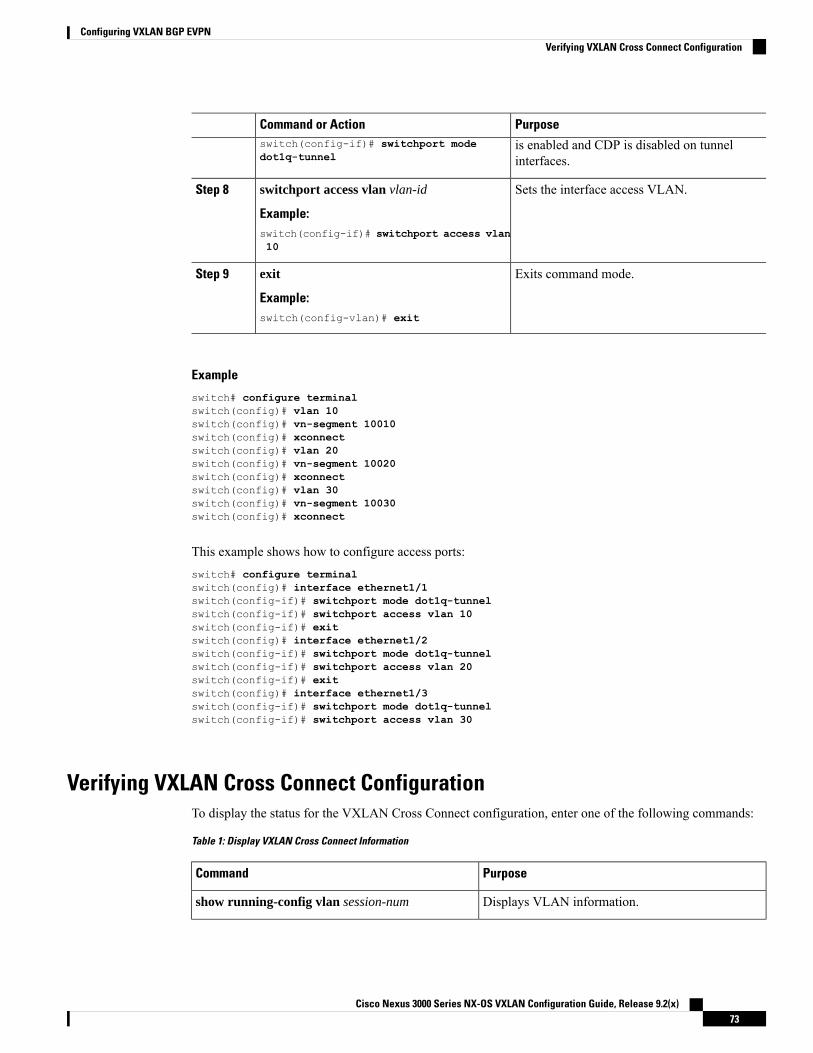
PurposeCommand or Actionswitch(config-if)# switchport modedot1q-tunnel
is enabled and CDP is disabled on tunnelinterfaces.
Sets the interface access VLAN.switchport access vlan vlan-id
Example:
Step 8
switch(config-if)# switchport access vlan10
Exits command mode.exit
Example:
Step 9
switch(config-vlan)# exit
Example
switch# configure terminalswitch(config)# vlan 10switch(config)# vn-segment 10010switch(config)# xconnectswitch(config)# vlan 20switch(config)# vn-segment 10020switch(config)# xconnectswitch(config)# vlan 30switch(config)# vn-segment 10030switch(config)# xconnect
This example shows how to configure access ports:switch# configure terminalswitch(config)# interface ethernet1/1switch(config-if)# switchport mode dot1q-tunnelswitch(config-if)# switchport access vlan 10switch(config-if)# exitswitch(config)# interface ethernet1/2switch(config-if)# switchport mode dot1q-tunnelswitch(config-if)# switchport access vlan 20switch(config-if)# exitswitch(config)# interface ethernet1/3switch(config-if)# switchport mode dot1q-tunnelswitch(config-if)# switchport access vlan 30
Verifying VXLAN Cross Connect ConfigurationTo display the status for the VXLAN Cross Connect configuration, enter one of the following commands:
Table 1: Display VXLAN Cross Connect Information
PurposeCommand
Displays VLAN information.show running-config vlan session-num
Cisco Nexus 3000 Series NX-OS VXLAN Configuration Guide, Release 9.2(x)73
Configuring VXLAN BGP EVPNVerifying VXLAN Cross Connect Configuration

PurposeCommand
Displays VXLAN VNI status.show nve vni
Displays VXLAN VNI status per VNI.show nve vni session-num
Example of the show run vlan 503 command:switch(config)# sh run vlan 503
!Command: show running-config vlan 503!Running configuration last done at: Mon Jul 9 13:46:03 2018!Time: Tue Jul 10 14:12:04 2018
version 9.2(1) Bios:version 07.64vlan 503vlan 503vn-segment 5503xconnect
Example of the show nve vni 5503 command:switch(config)# sh nve vni 5503Codes: CP - Control Plane DP - Data Plane
UC - Unconfigured SA - Suppress ARPSU - Suppress Unknown Unicast
Interface VNI Multicast-group State Mode Type [BD/VRF] Flags--------- -------- ----------------- ----- ---- ------------------ -----nve1 5503 225.5.0.3 Up CP L2 [503] SA Xconn
Example of the show nve vni command:switch(config)# sh nve vniCodes: CP - Control Plane DP - Data Plane
UC - Unconfigured SA - Suppress ARPSU - Suppress Unknown Unicast
Interface VNI Multicast-group State Mode Type [BD/VRF] Flags--------- -------- ----------------- ----- ---- ------------------ -----nve1 5501 225.5.0.1 Up CP L2 [501] SAnve1 5502 225.5.0.2 Up CP L2 [502] SAnve1 5503 225.5.0.3 Up CP L2 [503] SA Xconnnve1 5504 UnicastBGP Up CP L2 [504] SA Xconnnve1 5505 225.5.0.5 Up CP L2 [505] SA Xconnnve1 5506 UnicastBGP Up CP L2 [506] SA Xconnnve1 5507 225.5.0.7 Up CP L2 [507] SA Xconnnve1 5510 225.5.0.10 Up CP L2 [510] SA Xconnnve1 5511 225.5.0.11 Up CP L2 [511] SA Xconnnve1 5512 225.5.0.12 Up CP L2 [512] SA Xconnnve1 5513 UnicastBGP Up CP L2 [513] SA Xconnnve1 5514 225.5.0.14 Up CP L2 [514] SA Xconnnve1 5515 UnicastBGP Up CP L2 [515] SA Xconnnve1 5516 UnicastBGP Up CP L2 [516] SA Xconnnve1 5517 UnicastBGP Up CP L2 [517] SA Xconnnve1 5518 UnicastBGP Up CP L2 [518] SA Xconn
Cisco Nexus 3000 Series NX-OS VXLAN Configuration Guide, Release 9.2(x)74
Configuring VXLAN BGP EVPNVerifying VXLAN Cross Connect Configuration

C H A P T E R 5Configuring VXLAN OAM
This chapter contains the following sections:
• VXLAN OAM Overview, on page 75• Loopback (Ping) Message, on page 76• Traceroute or Pathtrace Message, on page 77• Configuring VXLAN OAM, on page 79• Configuring NGOAM Profile, on page 82• NGOAM Authentication, on page 83
VXLAN OAM OverviewThe VXLAN operations, administration, and maintenance (OAM) protocol is a protocol for installing,monitoring, and troubleshooting Ethernet networks to enhancemanagement in VXLANbased overlay networks.
Cisco Nexus 3500 Series switches do not support VXLAN OAM on Cisco NX-OS Release 7.0(3)I7(2) andthe previous releases.
Similar to ping, traceroute, or pathtrace utilities that allow quick determination of the problems in the IPnetworks, equivalent troubleshooting tools have been introduced to diagnose the problems in the VXLANnetworks. The VXLAN OAM tools, for example, ping, pathtrace, and traceroute provide the reachabilityinformation to the hosts and the VTEPs in a VXLAN network. The OAM channel is used to identify the typeof the VXLAN payload that is present in these OAM packets.
There are two types of payloads supported:
• Conventional ICMP packet to the destination to be tracked
• Special NVO3 draft Tissa OAM header that carries useful information
The ICMP channel helps to reach the traditional hosts or switches that do not support the new OAM packetformats. The NVO3 draft Tissa channels helps to reach the supported hosts or switches and carries the importantdiagnostic information. The VXLAN NVO3 draft Tissa OAM messages may be identified via the reservedOAM EtherType or by using a well-known reserved source MAC address in the OAM packets depending onthe implementation on different platforms. This constitutes a signature for recognition of the VXLAN OAMpackets. The VXLAN OAM tools are categorized as shown in table below.
Cisco Nexus 3000 Series NX-OS VXLAN Configuration Guide, Release 9.2(x)75

Table 2: VXLAN OAM Tools
ToolsCategory
Loopback MessageFault Verification
Path Trace MessageFault Isolation
Delay Measurement, Loss MeasurementPerformance
Address Binding Verification, IP End Station Locator,Error Notification, OAM Command Messages, andDiagnostic Payload Discovery for ECMP Coverage
Auxiliary
Loopback (Ping) MessageThe loopback message (The ping and the loopback messages are the same and they are used interchangeablyin this guide) is used for the fault verification. The loopback message utility is used to detect various errorsand the path failures. Consider the topology in the following example where there are three core (spine)switches labeled Spine 1, Spine 2, and Spine 3 and five leaf switches connected in a Clos topology. The pathof an example loopback message initiated from Leaf 1 for Leaf 5 is displayed when it traverses via Spine 3.When the loopback message initiated by Leaf 1 reaches Spine 3, it forwards it as VXLAN encapsulated datapacket based on the outer header. The packet is not sent to the software on Spine 3. On Leaf 3, based on theappropriate loopback message signature, the packet is sent to the software VXLAN OAM module, that inturn, generates a loopback response that is sent back to the originator Leaf 1.
The loopback (ping) message can be destined to VM or to the (VTEP on) leaf switch. This ping message canuse different OAM channels. If the ICMP channel is used, the loopback message can reach all the way to theVM if the VM's IP address is specified. If NVO3 draft Tissa channel is used, this loopback message isterminated on the leaf switch that is attached to the VM, as the VMs do not support the NVO3 draft Tissaheaders in general. In that case, the leaf switch replies back to this message indicating the reachability of theVM. The ping message supports the following reachability options:
Ping
Check the network reachability (Ping command):
• From Leaf 1 (VTEP 1) to Leaf 2 (VTEP 2) (ICMP or NVO3 draft Tissa channel)
• From Leaf 1 (VTEP 1) to VM 2 (host attached to another VTEP) (ICMP or NVO3 draft Tissa channel)
Cisco Nexus 3000 Series NX-OS VXLAN Configuration Guide, Release 9.2(x)76
Configuring VXLAN OAMLoopback (Ping) Message

Figure 5: Loopback Message
Traceroute or Pathtrace MessageThe traceroute or pathtrace message is used for the fault isolation. In a VXLAN network, it may be desirableto find the list of switches that are traversed by a frame to reach the destination. When the loopback test froma source switch to a destination switch fails, the next step is to find out the offending switch in the path. Theoperation of the path trace message begins with the source switch transmitting a VXLAN OAM frame witha TTL value of 1. The next hop switch receives this frame, decrements the TTL, and on finding that the TTLis 0, it transmits a TTL expiry message to the sender switch. The sender switch records this message as anindication of success from the first hop switch. Then the source switch increases the TTL value by one in thenext path trace message to find the second hop. At each new transmission, the sequence number in the messageis incremented. Each intermediate switch along the path decrements the TTL value by 1 as is the case withregular VXLAN forwarding.
This process continues until a response is received from the destination switch, or the path trace processtimeout occurs, or the hop count reaches a maximum configured value. The payload in the VXLAN OAMframes is referred to as the flow entropy. The flow entropy can be populated so as to choose a particular pathamong multiple ECMP paths between a source and destination switch. The TTL expiry message may also begenerated by the intermediate switches for the actual data frames. The same payload of the original path tracerequest is preserved for the payload of the response.
The traceroute and pathtrace messages are similar, except that traceroute uses the ICMP channel, whereaspathtrace use the NVO3 draft Tissa channel. Pathtrace uses the NVO3 draft Tissa channel, carrying additionaldiagnostic information, for example, interface load and statistics of the hops taken by these messages. If an
Cisco Nexus 3000 Series NX-OS VXLAN Configuration Guide, Release 9.2(x)77
Configuring VXLAN OAMTraceroute or Pathtrace Message
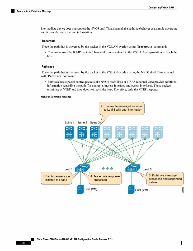
intermediate device does not support the NVO3 draft Tissa channel, the pathtrace behaves as a simple tracerouteand it provides only the hop information.
Traceroute
Trace the path that is traversed by the packet in the VXLAN overlay using Traceroute command:
• Traceroute uses the ICMP packets (channel-1), encapsulated in the VXLAN encapsulation to reach thehost
Pathtrace
Trace the path that is traversed by the packet in the VXLAN overlay using the NVO3 draft Tissa channelwith Pathtrace command:
• Pathtrace uses special control packets like NVO3 draft Tissa or TISSA (channel-2) to provide additionalinformation regarding the path (for example, ingress interface and egress interface). These packetsterminate at VTEP and they does not reach the host. Therefore, only the VTEP responds.
Figure 6: Traceroute Message
Cisco Nexus 3000 Series NX-OS VXLAN Configuration Guide, Release 9.2(x)78
Configuring VXLAN OAMTraceroute or Pathtrace Message
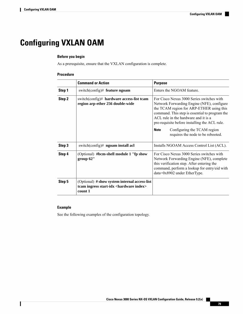
Configuring VXLAN OAMBefore you begin
As a prerequisite, ensure that the VXLAN configuration is complete.
Procedure
PurposeCommand or Action
Enters the NGOAM feature.switch(config)# feature ngoamStep 1
For Cisco Nexus 3000 Series switches withNetwork Forwarding Engine (NFE), configure
switch(config)# hardware access-list tcamregion arp-ether 256 double-wide
Step 2
the TCAM region for ARP-ETHER using thiscommand. This step is essential to program theACL rule in the hardware and it is apre-requisite before installing the ACL rule.
Configuring the TCAM regionrequires the node to be rebooted.
Note
Installs NGOAM Access Control List (ACL).switch(config)# ngoam install aclStep 3
For Cisco Nexus 3000 Series switches withNetwork Forwarding Engine (NFE), complete
(Optional) #bcm-shell module 1 "fp showgroup 62"
Step 4
this verification step. After entering thecommand, perform a lookup for entry/eid withdata=0x8902 under EtherType.
(Optional) # show system internal access-listtcam ingress start-idx <hardware index>count 1
Step 5
Example
See the following examples of the configuration topology.
Cisco Nexus 3000 Series NX-OS VXLAN Configuration Guide, Release 9.2(x)79
Configuring VXLAN OAMConfiguring VXLAN OAM
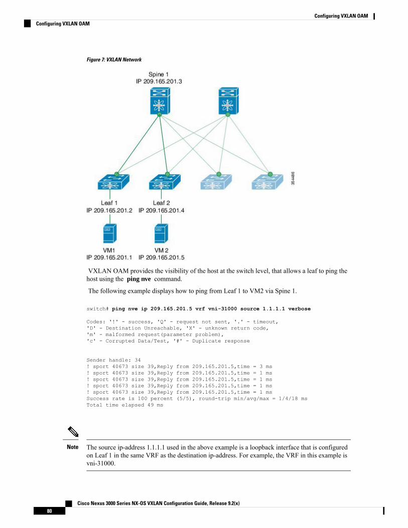
Figure 7: VXLAN Network
VXLAN OAM provides the visibility of the host at the switch level, that allows a leaf to ping thehost using the ping nve command.
The following example displays how to ping from Leaf 1 to VM2 via Spine 1.
switch# ping nve ip 209.165.201.5 vrf vni-31000 source 1.1.1.1 verbose
Codes: '!' - success, 'Q' - request not sent, '.' - timeout,'D' - Destination Unreachable, 'X' - unknown return code,'m' - malformed request(parameter problem),'c' - Corrupted Data/Test, '#' - Duplicate response
Sender handle: 34! sport 40673 size 39,Reply from 209.165.201.5,time = 3 ms! sport 40673 size 39,Reply from 209.165.201.5,time = 1 ms! sport 40673 size 39,Reply from 209.165.201.5,time = 1 ms! sport 40673 size 39,Reply from 209.165.201.5,time = 1 ms! sport 40673 size 39,Reply from 209.165.201.5,time = 1 msSuccess rate is 100 percent (5/5), round-trip min/avg/max = 1/4/18 msTotal time elapsed 49 ms
The source ip-address 1.1.1.1 used in the above example is a loopback interface that is configuredon Leaf 1 in the same VRF as the destination ip-address. For example, the VRF in this example isvni-31000.
Note
Cisco Nexus 3000 Series NX-OS VXLAN Configuration Guide, Release 9.2(x)80
Configuring VXLAN OAMConfiguring VXLAN OAM

The following example displays how to traceroute from Leaf 1 to VM 2 via Spine 1.
switch# traceroute nve ip 209.165.201.5 vrf vni-31000 source 1.1.1.1 verbose
Codes: '!' - success, 'Q' - request not sent, '.' - timeout,'D' - Destination Unreachable, 'X' - unknown return code,'m' - malformed request(parameter problem),'c' - Corrupted Data/Test, '#' - Duplicate response
Traceroute request to peer ip 209.165.201.4 source ip 209.165.201.2Sender handle: 361 !Reply from 209.165.201.3,time = 1 ms2 !Reply from 209.165.201.4,time = 2 ms3 !Reply from 209.165.201.5,time = 1 ms
The following example displays how to pathtrace from Leaf 2 to Leaf 1.switch# pathtrace nve ip 209.165.201.4 vni 31000 verbose
Path trace Request to peer ip 209.165.201.4 source ip 209.165.201.2
Sender handle: 42TTL Code Reply
IngressI/f EgressI/f State======================================================================1 !Reply from 209.165.201.3, Eth5/5/1 Eth5/5/2 UP/UP2 !Reply from 209.165.201.4, Eth1/3 Unknown UP/DOWN
The following example displays how to MAC ping from Leaf 2 to Leaf 1 using NVO3 draft Tissachannel:switch# ping nve mac 0050.569a.7418 2901 ethernet 1/51 profile 4 verbose
Codes: '!' - success, 'Q' - request not sent, '.' - timeout,'D' - Destination Unreachable, 'X' - unknown return code,'m' - malformed request(parameter problem),'c' - Corrupted Data/Test, '#' - Duplicate response
Sender handle: 408!!!!Success rate is 100 percent (5/5), round-trip min/avg/max = 4/4/5 msTotal time elapsed 104 ms
switch# show run ngoamfeature ngoamngoam profile 4oam-channel 2ngoam install acl
The following example displays how to pathtrace based on a payload from Leaf 2 to Leaf 1:
switch# pathtrace nve ip unknown vrf vni-31000 payload mac-addr 0050.569a.d927 0050.569a.a4faip 209.165.201.5 209.165.201.1 port 15334 12769 proto 17 payload-end
Codes: '!' - success, 'Q' - request not sent, '.' - timeout,'D' - Destination Unreachable, 'X' - unknown return code,'m' - malformed request(parameter problem),
Cisco Nexus 3000 Series NX-OS VXLAN Configuration Guide, Release 9.2(x)81
Configuring VXLAN OAMConfiguring VXLAN OAM

'c' - Corrupted Data/Test, '#' - Duplicate response
Path trace Request to peer ip 209.165.201.4 source ip 209.165.201.2Sender handle: 46TTL Code Reply IngressI/f EgressI/f State======================================================================1 !Reply from 209.165.201.3, Eth5/5/1 Eth5/5/2 UP/UP2 !Reply from 209.165.201.4, Eth1/3 Unknown UP/DOWN
Configuring NGOAM ProfileComplete the following steps to configure NGOAM profile.
Procedure
PurposeCommand or Action
Enables or disables NGOAM featureswitch(config)#[no] feature ngoamStep 1
Configures OAM profile. The range for theprofile-id is <1 – 1023>. This command does
switch(config)#[no] ngoam profile<profile-id>
Step 2
not have a default value. Enters theconfig-ngoam-profile submode to configureNGOAM specific commands.
All profiles have default values andthe show run all CLI commanddisplays them. The default values arenot visible through the show runCLI command.
Note
Displays the options for configuring NGOAMprofile.
switch(config-ng-oam-profile)# ?
Example:
Step 3
switch(config-ng-oam-profile)# ?description Configure description ofthe profiledot1q Encapsulation dot1q/bdflow Configure ngoam flowhop Configure ngoam hop count
interface Configure ngoam egressinterfaceno Negate a command or set
its defaultsoam-channel Oam-channel usedpayload Configure ngoam payloadsport Configure ngoam Udp sourceport range
Cisco Nexus 3000 Series NX-OS VXLAN Configuration Guide, Release 9.2(x)82
Configuring VXLAN OAMConfiguring NGOAM Profile

Example
See the following examples for configuring an NGOAM profile and for configuring NGOAM flow.
switch(config)#ngoam profile 1oam-channel 1flow forwardpayload pad 0x2sport 12345, 54321
switch(config-ngoam-profile)#flow {forward }Enters config-ngoam-profile-flow submode to configure forward flow entropy specificinformation
NGOAM AuthenticationNGOAM provides the interface statistics in the pathtrace response. Beginning with Cisco NX-OS Release7.0(3)I6(1), NGOAM authenticates the pathtrace requests to provide the statistics by using the HMAC MD5authentication mechanism.
NGOAM authentication validates the pathtrace requests before providing the interface statistics. NGOAMauthentication takes effect only for the pathtrace requests with req-stats option. All the other commands arenot affectedwith the authentication configuration. If NGOAMauthentication key is configured on the requestingnode, NGOAM runs the MD5 algorithm using this key to generate the 16-bit MD5 digest. This digest isencoded as type-length-value (TLV) in the pathtrace request messages.
When the pathtrace request is received, NGOAM checks for the req-stats option and the local NGOAMauthentication key. If the local NGOAM authentication key is present, it runs MD5 using the local key on therequest to generate the MD5 digest. If both digests match, it includes the interface statistics. If both digestsdo not match, it sends only the interface names. If an NGOAM request comes with the MD5 digest but nolocal authentication key is configured, it ignores the digest and sends all the interface statistics. To secure anentire network, configure the authentication key on all nodes.
To configure the NGOAM authentication key, use the ngoam authentication-key <key> CLI command. Usethe show running-config ngoam CLI command to display the authentication key.
switch# show running-config ngoam!Time: Tue Mar 28 18:21:50 2017version 7.0(3)I6(1)feature ngoamngoam profile 1oam-channel 2
ngoam profile 3ngoam install aclngoam authentication-key 987601ABCDEF
In the following example, the same authentication key is configured on the requesting switch and the respondingswitch.
switch# pathtrace nve ip 12.0.22.1 profile 1 vni 31000 req-stats verPath trace Request to peer ip 12.0.22.1 source ip 11.0.22.1Hop Code ReplyIP IngressI/f EgressI/f State
Cisco Nexus 3000 Series NX-OS VXLAN Configuration Guide, Release 9.2(x)83
Configuring VXLAN OAMNGOAM Authentication

====================================================1 !Reply from 55.55.55.2, Eth5/7/1 Eth5/7/2 UP / UPInput Stats: PktRate:0 ByteRate:0 Load:0 Bytes:339573434 unicast:14657 mcast:307581
bcast:67 discards:0 errors:3 unknown:0 bandwidth:42949672970000000Output Stats: PktRate:0 ByteRate:0 load:0 bytes:237399176 unicast:2929 mcast:535710bcast:10408 discards:0 errors:0 bandwidth:429496729700000002 !Reply from 12.0.22.1, Eth1/7 Unknown UP / DOWNInput Stats: PktRate:0 ByteRate:0 Load:0 Bytes:4213416 unicast:275 mcast:4366 bcast:3
discards:0 errors:0 unknown:0 bandwidth:42949672970000000switch# conf tswitch(config)# no ngoam authentication-key 123456789switch(config)# end
In the following example, an authentication key is not configured on the requesting switch. Therefore, theresponding switch does not send any interface statistics. The intermediate node does not have any authenticationkey configured and it always replies with the interface statistics.
switch# pathtrace nve ip 12.0.22.1 profile 1 vni 31000 req-stats verPath trace Request to peer ip 12.0.22.1 source ip 11.0.22.1Sender handle: 10Hop Code ReplyIP IngressI/f EgressI/f State====================================================1 !Reply from 55.55.55.2, Eth5/7/1 Eth5/7/2 UP / UPInput Stats: PktRate:0 ByteRate:0 Load:0 Bytes:339580108 unicast:14658 mcast:307587
bcast:67 discards:0 errors:3 unknown:0 bandwidth:42949672970000000Output Stats: PktRate:0 ByteRate:0 load:0 bytes:237405790 unicast:2929 mcast:535716bcast:10408 discards:0 errors:0 bandwidth:429496729700000002 !Reply from 12.0.22.1, Eth1/17 Unknown UP / DOWN
Cisco Nexus 3000 Series NX-OS VXLAN Configuration Guide, Release 9.2(x)84
Configuring VXLAN OAMNGOAM Authentication
C H A P T E R 6Configuring VXLAN Multihoming
This chapter contains the following sections:
• VXLAN EVPN Multihoming Overview , on page 85• Configuring VXLAN EVPN Multihoming, on page 88• Configuring Layer 2 Gateway STP, on page 91• Configuring VXLAN EVPN Multihoming Traffic Flows, on page 95• Configuring VLAN Consistency Checking, on page 107• Configuring ESI ARP Suppression, on page 109
VXLAN EVPN Multihoming Overview
Introduction to MultihomingCisco Nexus platforms support vPC-based multihoming, where a pair of switches act as a single device forredundancy and both switches function in an active mode. With Cisco Nexus 31128PQ switch and 3100-Vplatform switches in VXLANBGPEVPN environment, there are two solutions to support Layer 2multihoming;the solutions are based on the Traditional vPC (emulated or virtual IP address) and the BGP EVPN techniques.
Traditional vPC utilizes a consistency check that is a mechanism used by the two switches that are configuredas a vPC pair to exchange and verify their configuration compatibility. The BGP EVPN technique does nothave the consistency check mechanism, but it uses LACP to detect the misconfigurations. It also eliminatesthe MCT link that is traditionally used by vPC and it offers more flexibility as each VTEP can be a part ofone or more redundancy groups. It can potentially support many VTEPs in a given group.
BGP EVPN Multihoming TerminologySee this section for the terminology used in BGP EVPN multihoming:
• EVI: EVPN instance represented by the VNI.
• MAC-VRF:A container to house virtual forwarding table forMAC addresses. A unique route distinguisherand import/export target can be configured per MAC-VRF.
• ES: Ethernet Segment that can constitute a set of bundled links.
• ESI: Ethernet Segment Identifier to represent each ES uniquely across the network.
Cisco Nexus 3000 Series NX-OS VXLAN Configuration Guide, Release 9.2(x)85

EVPN Multihoming ImplementationThe EVPN overlay draft specifies adaptations to the BGP MPLS based EVPN solution to enable it to beapplied as a network virtualization overlay with VXLAN encapsulation. The Provider Edge (PE) node rolein BGP MPLS EVPN is equivalent to VTEP/Network Virtualization Edge device (NVE), where VTEPs usecontrol plane learning and distribution via BGP for remote addresses instead of data plane learning.
There are 5 different route types currently defined:
• Ethernet Auto-Discovery (EAD) Route
• MAC advertisement Route
• Inclusive Multicast Route
• Ethernet Segment Route
• IP Prefix Route
BGP EVPN running on Cisco NX-OS uses route type-2 to advertise MAC and IP (host) information, routetype-3 to carry VTEP information (specifically for ingress replication), and the EVPN route type-5 allowsadvertisements of IPv4 or IPv6 prefixes in an Network Layer Reachability Information (NLRI) with no MACaddresses in the route key.
With the introduction of EVPNmultihoming, Cisco NX-OS software utilizes Ethernet Auto-discovery (EAD)route, where Ethernet Segment Identifier and the Ethernet Tag ID are considered to be part of the prefix inthe NLRI. Since the end points reachability is learned via the BGP control plane, the network convergencetime is a function of the number of MAC/IP routes that must be withdrawn by the VTEP in case of a failurescenario. To deal with such condition, each VTEP advertises a set of one or more Ethernet Auto-Discoveryper ES routes for each locally attached Ethernet Segment and upon a failure condition to the attached segment,the VTEP withdraws the corresponding set of Ethernet Auto-Discovery per ES routes.
Ethernet Segment Route is the other route type that is being used by Cisco NX-OS software with EVPNmultihoming, mainly for Designated Forwarder (DF) election for the BUM traffic. If the Ethernet Segmentis multihomed, the presence of multiple DFs could result in forwarding the loops in addition to the potentialpacket duplication. Therefore, the Ethernet Segment Route (Type 4) is used to elect the Designated Forwarderand to apply Split Horizon Filtering. All VTEPs/PEs that are configured with an Ethernet Segment originatethis route.
To summarize the new implementation concepts for the EVPN multihoming:
• EAD/ES: Ethernet Auto Discovery Route per ES that is also referred to as type-1 route. This route isused to converge the traffic faster during access failure scenarios. This route has Ethernet Tag of0xFFFFFFFF.
• EAD/EVI: Ethernet Auto Discovery Route per EVI that is also referred to as type-1 route. This route isused for aliasing and load balancing when the traffic only hashes to one of the switches. This route cannothave Ethernet Tag value of 0xFFFFFF to differentiate it from the EAD/ES route.
• ES: Ethernet Segment route that is also referred to as type-4 route. This route is used for DF election forBUM traffic.
• Aliasing: It is used for load balancing the traffic to all the connected switches for a given Ethernet Segmentusing the type-1 EAD/EVI route. This is done irrespective of the switch where the hosts are actuallylearned.
Cisco Nexus 3000 Series NX-OS VXLAN Configuration Guide, Release 9.2(x)86
Configuring VXLAN MultihomingEVPN Multihoming Implementation

• Mass Withdrawal: It is used for fast convergence during the access failure scenarios using the type-1EAD/ES route.
• DF Election: It is used to prevent forwarding of the loops and the duplicates as only a single switch isallowed to decap and forward the traffic for a given Ethernet Segment.
• Split Horizon: It is used to prevent forwarding of the loops and the duplicates for the BUM traffic. Onlythe BUM traffic that originates from a remote site is allowed to be forwarded to a local site.
EVPN Multihoming Redundancy GroupConsider the dually homed topology, where switches L1 and L2 are distributed anycast VXLAN gatewaysthat perform Integrated Routing and Bridging (IRB). Host H2 is connected to an access switch that is duallyhomed to both L1 and L2.
The access switch is connected to L1 and L2 via a bundled pair of physical links. The switch is not aware thatthe bundle is configured on two different devices on the other side. However, both L1 and L2 must be awarethat they are a part of the same bundle.
Note that there is no Multichassis EtherChannel Trunk (MCT) link between L1 and L2 switches and eachswitch can have similar multiple bundle links that are shared with the same set of neighbors.
To make the switches L1 and L2 aware that they are a part of the same bundle link, the NX-OS softwareutilizes the Ethernet Segment Identifier (ESI) and the system MAC address (system-mac) that is configuredunder the interface (PO).
Ethernet Segment IdentifierEVPN introduces the concept of Ethernet Segment Identifier (ESI). Each switch is configured with a 10 byteESI value under the bundled link that they share with the multihomed neighbor. The ESI value can be manuallyconfigured or auto-derived.
LACP BundlingLACP can be turned ON for detecting ESImisconfigurations on themultihomed port channel bundle as LACPsends the ESI configured MAC address value to the access switch. LACP is not mandated along with ESI. Agiven ESI interface (PO) shares the same ESI ID across the VTEPs in the group.
The access switch receives the same configured MAC value from both switches (L1 and L2). Therefore, itputs the bundled link in the UP state. Since the ES MAC can be shared across all the Ethernet-segments onthe switch, LACP PDUs use ES MAC as system MAC address and the admin_key carries the ES ID.
Cisco recommends running LACP between the switches and the access devices since LACP PDUs have amechanism to detect and act on the misconfigured ES IDs. In case there is mismatch on the configured ESID under the same PO, LACP brings down one of the links (first link that comes online stays up). By default,on most Cisco Nexus platforms, LACP sets a port to the suspended state if it does not receive an LACP PDUfrom the peer. This is based on the lacp suspend-individual command that is enabled by default. This commandhelps in preventing loops that are created due to the ESI configuration mismatch. Therefore, it is recommendedto enable this command on the port-channels on the access switches and the servers.
In some scenarios (for example, POAP or NetBoot), it can cause the servers to fail to boot up because theyrequire LACP to logically bring up the port. In case you are using static port channel and you have mismatchedES IDs, the MAC address gets learned from both L1 and L2 switches. Therefore, both the switches advertise
Cisco Nexus 3000 Series NX-OS VXLAN Configuration Guide, Release 9.2(x)87
Configuring VXLAN MultihomingEVPN Multihoming Redundancy Group

the sameMAC address belonging to different ES IDs that triggers theMAC address move scenario. Eventually,no traffic is forwarded to that node for the MAC addresses that are learned on both L1 and L2 switches.
Guidelines and Limitations for VXLAN EVPN MultihomingSee the following limitations for configuring VXLAN EVPN multihoming:
• EVPN multihoming is supported on the Cisco Nexus 3132Q-V, 31108PC-V, 31108TC-V, and 3132-Zplatform switches only.
• ARP suppression is supported with EVPN multihoming.
• EVPN multihoming is supported with multihoming to two switches only.
• Switchport trunk native VLAN is not supported on the trunk interfaces.
• Cisco recommends enabling LACP on ES PO.
• IPV6 is currently not supported.
Configuring VXLAN EVPN Multihoming
Enabling EVPN MultihomingCisco NX-OS allows either vPC based EVPN multihoming or ESI based EVPN multihoming. Both featuresshould not be enabled together. ESI basedmultihoming is enabled using evpn esi multihomingCLI command.It is important to note that the command for ESI multihoming enables the Ethernet-segment configurationsand the generation of Ethernet-segment routes on the switches.
The receipt of type-1 and type-2 routes with valid ESI and the path-list resolution are not tied to the evpn esimultihoming command. If the switch receives MAC/MAC-IP routes with valid ESI and the command is notenabled, the ES based path resolution logic still applies to these remote routes. This is required forinteroperability between the vPC enabled switches and the ESI enabled switches.
Complete the following steps to configure EVPN multihoming:
Before you begin
VXLAN should be configured with BGP-EVPN before enabling EVPN ESI multihoming.
Procedure
PurposeCommand or Action
Enables EVPN multihoming globally.evpn esi multihomingStep 1
The ESI Port Channel remains down for 30seconds after the core facing interfaces are up.
ethernet-segment delay-restore time 30Step 2
Enables VLAN consistency check.vlan-consistency-checkStep 3
Cisco Nexus 3000 Series NX-OS VXLAN Configuration Guide, Release 9.2(x)88
Configuring VXLAN MultihomingGuidelines and Limitations for VXLAN EVPN Multihoming

PurposeCommand or Action
Enables BGP maximum-path to enable ECMPfor theMAC routes. Otherwise, theMAC routes
address-family l2vpn evpn maximum-paths<>maximum-paths ibgp <>
Step 4
have only 1 VTEP as the next-hop. ThisExample: configuration is needed under BGP in Global
level.address-family l2vpn evpnmaximum-paths 64maximum-paths ibgp 64
Enables EVPNmultihoming core-links. It tracksthe uplink interfaces towards the core. If all
evpn multihoming core-trackingStep 5
uplinks are down, the local ES based the POsis shut down/suspended. This is mainly used toavoid black-holing South-to-North traffic whenno uplinks are available.
Configures the local Ethernet Segment ID. TheES ID has to match on VTEPs where the PO is
interface port-channel Ethernet-segment<>System-mac <>
Step 6
multihomed. The Ethernet Segment ID shouldbe unique per PO.Example:
ethernet-segment 11system-mac 0000.0000.0011 Configures the local system-mac ID that has to
match on the VTEPs where the PO ismultihomed. The system-mac address can beshared across multiple POs.
Configures the TCAM. This command is usedto configure the split horizon ACLs in the
hardware access-list tcam regionvpc-convergence 256
Step 7
hardware. This command avoids BUM trafficduplication on the shared ES POs.Example:
hardware access-list tcam regionvpc-convergence 256
VXLAN EVPN Multihoming Configuration ExamplesSee the sample VXLAN EVPN multihoming configuration on the switches:
Switch 1 (L1)
evpn esi multihoming
ethernet-segment delay-restore time 180vlan-consistency-checkrouter bgp 1001
address-family l2vpn evpnmaximum-paths ibgp 2
interface Ethernet2/1no switchportevpn multihoming core-trackingmtu 9216ip address 10.1.1.1/30ip pim sparse-mode
Cisco Nexus 3000 Series NX-OS VXLAN Configuration Guide, Release 9.2(x)89
Configuring VXLAN MultihomingVXLAN EVPN Multihoming Configuration Examples

no shutdown
interface Ethernet2/2no switchportevpn multihoming core-trackingmtu 9216ip address 10.1.1.5/30ip pim sparse-modeno shutdown
interface port-channel11switchport mode trunkswitchport trunk allowed vlan 901-902,1001-1050ethernet-segment 2011system-mac 0000.0000.2011
mtu 9216
Switch 2 (L2)
evpn esi multihoming
ethernet-segment delay-restore time 180vlan-consistency-checkrouter bgp 1001
address-family l2vpn evpnmaximum-paths ibgp 2
interface Ethernet2/1no switchportevpn multihoming core-trackingmtu 9216ip address 10.1.1.2/30ip pim sparse-modeno shutdown
interface Ethernet2/2no switchportevpn multihoming core-trackingmtu 9216ip address 10.1.1.6/30ip pim sparse-modeno shutdown
interface port-channel11switchport mode trunkswitchport access vlan 1001switchport trunk allowed vlan 901-902,1001-1050ethernet-segment 2011system-mac 0000.0000.2011
mtu 9216
Cisco Nexus 3000 Series NX-OS VXLAN Configuration Guide, Release 9.2(x)90
Configuring VXLAN MultihomingVXLAN EVPN Multihoming Configuration Examples

Configuring Layer 2 Gateway STP
Layer 2 Gateway STP OverviewEVPN multihoming is supported with the Layer 2 Gateway Spanning Tree Protocol (L2G-STP). The Layer2 Gateway Spanning Tree Protocol (L2G-STP) builds a loop-free tree topology. However, the Spanning TreeProtocol root must always be in the VXLAN fabric. A bridge ID for the Spanning Tree Protocol consists ofa MAC address and the bridge priority. When the system is running in the VXLAN fabric, the systemautomatically assigns the VTEPs with the MAC address c84c.75fa.6000 from a pool of reserved MACaddresses. As a result, each switch uses the same MAC address for the bridge ID emulating a single logicalpseudo root.
The Layer 2 Gateway Spanning Tree Protocol (L2G-STP) is disabled by default on EVPN ESI multihomingVLANs. Use the spanning-tree domain enable CLI command to enable L2G-STP on all VTEPs. WithL2G-STP enabled, the VXLAN fabric (all VTEPs) emulates a single pseudo root switch for the customeraccess switches. The L2G-STP is initiated to run on all VXLAN VLANs by default on boot up and the rootis fixed on the overlay. With L2G-STP, the root-guard gets enabled by default on all the access ports. Usespanning-tree domain <id> to additionally enable Spanning Tree Topology ChangeNotification(STP-TCN),to be tunneled across the fabric.
All the access ports from VTEPs connecting to the customer access switches are in a desg forwarding stateby default. All ports on the customer access switches connecting to VTEPs are either in root-port forwardingor alt-port blocking state. The root-guard kicks in if better or superior STP information is received from thecustomer access switches and it puts the ports in the blk l2g_inc state to secure the root on the overlay-fabricand to prevent a loop.
Guidelines for Moving to Layer 2 Gateway STPComplete the following steps to move to Layer 2 gateway STP:
• With Layer 2 Gateway STP, root guard is enabled by default on all the access ports.
• With Layer 2 Gateway STP enabled, the VXLAN fabric (all VTEPs) emulates a single pseudo-rootswitch for the customer access switches.
• All access ports from VTEPs connecting to the customer access switches are in the Desg FWD state bydefault.
• All ports on customer access switches connecting to VTEPs are either in the root-port FWD or Altn BLKstate.
• Root guard is activated if superior spanning-tree information is received from the customer accessswitches. This process puts the ports in BLK L2GW_Inc state to secure the root on the VXLAN fabricand prevent a loop.
• Explicit domain ID configuration is needed to enable spanning-tree BPDU tunneling across the fabric.
• As a best practice, you should configure all VTEPs with the lowest spanning-tree priority of all switchesin the spanning-tree domain to which they are attached. By setting all the VTEPs as the root bridge, theentire VXLAN fabric appears to be one virtual bridge.
Cisco Nexus 3000 Series NX-OS VXLAN Configuration Guide, Release 9.2(x)91
Configuring VXLAN MultihomingConfiguring Layer 2 Gateway STP

• ESI interfaces should not be enabled in spanning-tree edge mode to allow Layer 2 Gateway STP to runacross the VTEP and access layer.
• You can continue to use ESIs or orphans (single-homed hosts) in spanning-tree edge mode if they directlyconnect to hosts or servers that do not run Spanning Tree Protocol and are end hosts.
• Configure all VTEPs that are connected by a common customer access layer in the same Layer 2 GatewaySTP domain. Ideally, all VTEPs on the fabric on which the hosts reside and to which the hosts can move.
• The Layer 2 Gateway STP domain scope is global, and all ESIs on a given VTEP can participate in onlyone domain.
• Mappings between Multiple Spanning Tree (MST) instances and VLANs must be consistent across theVTEPs in a given Layer 2 Gateway STP domain.
• Non-Layer 2 Gateway STP enabled VTEPs cannot be directly connected to Layer 2 Gateway STP-enabledVTEPs. Performing this action results in conflicts and disputes because the non-Layer 2 Gateway STPVTEP keeps sending BPDUs and it can steer the root outside.
• Keep the current edge and the BPDU filter configurations on both the Cisco Nexus switches and theaccess switches after upgrading to the latest build.
• Enable Layer 2 Gateway STP on all the switches with a recommended priority and the mst instancemapping as needed. Use the commands spanning-tree domain enable and spanning-tree mst<instance-id’s> priority 8192.
• Remove the BPDU filter configurations on the switch side first.
• Remove the BPDU filter configurations and the edge on the customer access switch.
Now the topology converges with Layer 2 Gateway STP and any blocking of the redundant connectionsis pushed to the access switch layer.
Enabling Layer 2 Gateway STP on a SwitchComplete the following steps to enable Layer 2 Gateway STP on a switch.
Procedure
PurposeCommand or Action
Enables Spanning Tree Protocol mode.spanning-tree mode <rapid-pvst, mst>Step 1
Enables Layer 2 Gateway STP on a switch. Itdisables Layer 2 Gateway STP on all EVPNESI multihoming VLANs.
spanning-tree domain enableStep 2
Explicit domain ID is needed to tunnel encodedBPDUs to the core and processes received fromthe core.
spanning-tree domain 1Step 3
Configures Spanning Tree Protocol priority.spanning-tree mst <id> priority 8192Step 4
Configures Spanning Tree Protocol priority.spanning-tree vlan <id> priority 8192Step 5
Cisco Nexus 3000 Series NX-OS VXLAN Configuration Guide, Release 9.2(x)92
Configuring VXLAN MultihomingEnabling Layer 2 Gateway STP on a Switch
PurposeCommand or Action
Disables Layer 2 Gateway STP on a VTEP.spanning-tree domain disableStep 6
Example
All Layer 2 Gateway STP VLANs should be set to a lower spanning-tree priority than thecustomer-edge (CE) topology to help ensure that the VTEP is the spanning-tree root for this VLAN.If the access switches have a higher priority, you can set the Layer 2 Gateway STP priority to 0 toretain the Layer 2 Gateway STP root in the VXLAN fabric. See the following configuration example:
switch# show spanning-tree summarySwitch is in mst mode (IEEE Standard)Root bridge for: MST0000L2 Gateway STP bridge for: MST0000L2 Gateway Domain ID: 1Port Type Default is disableEdge Port [PortFast] BPDU Guard Default is disabledEdge Port [PortFast] BPDU Filter Default is disabledBridge Assurance is enabledLoopguard Default is disabledPathcost method used is longPVST Simulation is enabledSTP-Lite is disabled
Name Blocking Listening Learning Forwarding STP Active---------------------- -------- --------- -------- ---------- ----------MST0000 0 0 0 12 12---------------------- -------- --------- -------- ---------- ----------1 mst 0 0 0 12 12
switch# show spanning-tree vlan 1001
MST0000Spanning tree enabled protocol mstp
Root ID Priority 8192Address c84c.75fa.6001 L2G-STP reserved mac+ domain idThis bridge is the rootHello Time 2 sec Max Age 20 sec Forward Delay 15 sec
Bridge ID Priority 8192 (priority 8192 sys-id-ext 0)Address c84c.75fa.6001Hello Time 2 sec Max Age 20 sec Forward Delay 15 sec
The output displays that the spanning-tree priority is set to 8192 (the default is 32768). Spanning-treepriority is set in multiples of 4096. The priority for individual instances is calculated as the priorityand the Instance_ID. In this case, the priority is calculated as 8192 + 0 = 8192.With Layer 2 GatewaySTP, access ports (VTEP ports connected to the access switches) have root guard enabled. If a superiorBPDU is received on an edge port of a VTEP, the port is placed in the Layer 2 Gateway inconsistentstate until the condition is cleared as displayed in the following example:
Cisco Nexus 3000 Series NX-OS VXLAN Configuration Guide, Release 9.2(x)93
Configuring VXLAN MultihomingEnabling Layer 2 Gateway STP on a Switch
2016 Aug 29 19:14:19 TOR9-leaf4 %$ VDC-1 %$ %STP-2-L2GW_BACKBONE_BLOCK: L2 Gateway Backboneport inconsistency blocking port Ethernet1/1 on MST0000.2016 Aug 29 19:14:19 TOR9-leaf4 %$ VDC-1 %$ %STP-2-L2GW_BACKBONE_BLOCK: L2 Gateway Backboneport inconsistency blocking port port-channel13 on MST0000.
switch# show spanning-tree
MST0000Spanning tree enabled protocol mstpRoot ID Priority 8192
Address c84c.75fa.6001This bridge is the rootHello Time 2 sec Max Age 20 sec Forward Delay 15 sec
Bridge ID Priority 8192 (priority 8192 sys-id-ext 0)Address c84c.75fa.6001Hello Time 2 sec Max Age 20 sec Forward Delay 15 sec
Interface Role Sts Cost Prio.Nbr Type---------------- ---- --- --------- -------- --------------------------------Po1 Desg FWD 20000 128.4096 Edge P2pPo2 Desg FWD 20000 128.4097 Edge P2pPo3 Desg FWD 20000 128.4098 Edge P2pPo12 Desg BKN*2000 128.4107 P2p *L2GW_IncPo13 Desg BKN*1000 128.4108 P2p *L2GW_IncEth1/1 Desg BKN*2000 128.1 P2p *L2GW_Inc
To disable Layer 2 Gateway STP on a VTEP, enter the spanning-tree domain disableCLI command.This command disables Layer 2 Gateway STP on all EVPN ESI multihomed VLANs. The bridgeMAC address is restored to the systemMAC address, and the VTEP may not necessarily be the root.In the following case, the access switch has assumed the root role because Layer 2 Gateway STP isdisabled:
switch(config)# spanning-tree domain disable
switch# show spanning-tree summarySwitch is in mst mode (IEEE Standard)Root bridge for: noneL2 Gateway STP is disabledPort Type Default is disableEdge Port [PortFast] BPDU Guard Default is disabledEdge Port [PortFast] BPDU Filter Default is disabledBridge Assurance is enabledLoopguard Default is disabledPathcost method used is longPVST Simulation is enabledSTP-Lite is disabled
Name Blocking Listening Learning Forwarding STP Active---------------------- -------- --------- -------- ---------- ----------MST0000 4 0 0 8 12---------------------- -------- --------- -------- ---------- ----------1 mst 4 0 0 8 12
switch# show spanning-tree vlan 1001
MST0000Spanning tree enabled protocol mstpRoot ID Priority 4096
Address 00c8.8ba6.5073
Cisco Nexus 3000 Series NX-OS VXLAN Configuration Guide, Release 9.2(x)94
Configuring VXLAN MultihomingEnabling Layer 2 Gateway STP on a Switch

Cost 0Port 4108 (port-channel13)Hello Time 2 sec Max Age 20 sec Forward Delay 15 sec
Bridge ID Priority 8192 (priority 8192 sys-id-ext 0)Address 5897.bd1d.db95Hello Time 2 sec Max Age 20 sec Forward Delay 15 sec
With Layer 2 Gateway STP, the access ports on VTEPs cannot be in an edge port, because theybehave like normal spanning-tree ports, receiving BPDUs from the access switches. In that case, theaccess ports on VTEPs lose the advantage of rapid transmission, instead forwarding on Ethernetsegment link flap. (They have to go through a proposal and agreement handshake before assumingthe FWD-Desg role).
Configuring VXLAN EVPN Multihoming Traffic Flows
EVPN Multihoming Local Traffic FlowsAll switches that are a part of the same redundancy group (as defined by the ESI) act as a single virtual switchwith respect to the access switch/host. However, there is no MCT link present to bridge and route the trafficfor local access.
Locally Bridged Traffic
Host H2 is dually homed whereas hosts H1 and H3 are single-homed (also known as orphans). The traffic isbridged locally from H1 to H2 via L1. However, if the packet needs to be bridged between the orphans H1and H3, the packet must be bridged via the VXLAN overlay.
Figure 8: Local Bridging at L1. H1->H3 bridging via VXLAN. In vPC, H1->H3 will be via MCT link.
Cisco Nexus 3000 Series NX-OS VXLAN Configuration Guide, Release 9.2(x)95
Configuring VXLAN MultihomingConfiguring VXLAN EVPN Multihoming Traffic Flows

Access Failure for Locally Bridged Traffic
If the ESI link at L1 fails, there is no path for the bridged traffic to reach from H1 to H2 except via the overlay.Therefore, the local bridged traffic takes the sub-optimal path, similar to the H1 to H3 orphan flow.
When such condition occurs, theMAC table entry for H2 changes from a local route pointing to a port channelinterface to a remote overlay route pointing to peer-ID of L2. The change gets percolated in the system fromBGP.
Note
Figure 9: ES1 failure on L1. H1->H2 is now bridged over VXLAN tunnel.
Core Failure for Locally Bridged Traffic
If switch L1 gets isolated from the core, it must not continue to attract access traffic, as it will not be able toencapsulate and send it on the overlay. This means that the access links must be brought down at L1 if L1loses core reachability. In this scenario, orphan H1 loses all connectivity to both remote and locally attachedhosts since there is no dedicated MCT link.
Cisco Nexus 3000 Series NX-OS VXLAN Configuration Guide, Release 9.2(x)96
Configuring VXLAN MultihomingEVPN Multihoming Local Traffic Flows
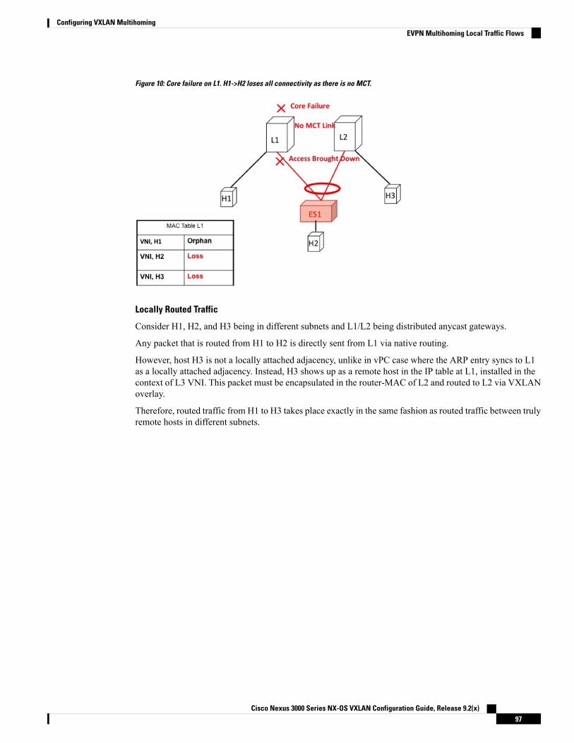
Figure 10: Core failure on L1. H1->H2 loses all connectivity as there is no MCT.
Locally Routed Traffic
Consider H1, H2, and H3 being in different subnets and L1/L2 being distributed anycast gateways.
Any packet that is routed from H1 to H2 is directly sent from L1 via native routing.
However, host H3 is not a locally attached adjacency, unlike in vPC case where the ARP entry syncs to L1as a locally attached adjacency. Instead, H3 shows up as a remote host in the IP table at L1, installed in thecontext of L3 VNI. This packet must be encapsulated in the router-MAC of L2 and routed to L2 via VXLANoverlay.
Therefore, routed traffic from H1 to H3 takes place exactly in the same fashion as routed traffic between trulyremote hosts in different subnets.
Cisco Nexus 3000 Series NX-OS VXLAN Configuration Guide, Release 9.2(x)97
Configuring VXLAN MultihomingEVPN Multihoming Local Traffic Flows

Figure 11: L1 is Distributed Anycast Gateway. H1, H2, and H3 are in different VLANs. H1->H3 routing happens via VXLAN tunnelencapsulation. In VPC, H3 ARP would have been synced via MCT and direct routing.
Access Failure for Locally Routed Traffic
In case the ESI link at switch L1 fails, there is no path for the routed traffic to reach from H1 to H2 exceptvia the overlay. Therefore, the local routed traffic takes the sub-optimal path, similar to the H1 to H3 orphanflow.
Figure 12: H1, H2, and H3 are in different VLANs. ESI fails on L1. H1->H2 routing happens via VXLAN tunnel encapsulation.
Cisco Nexus 3000 Series NX-OS VXLAN Configuration Guide, Release 9.2(x)98
Configuring VXLAN MultihomingEVPN Multihoming Local Traffic Flows

Core Failure for Locally Routed Traffic
If switch L1 gets isolated from the core, it must not continue to attract access traffic, as it will not be able toencapsulate and send it on the overlay. It means that the access links must be brought down at L1 if L1 losescore reachability.
In this scenario, orphan H1 loses all connectivity to both remote and locally attached hosts as there is nodedicated MCT link.
Figure 13: H1, H2, and H3 are in different VLANs. Core fails on L1. Access is brought down. H1 loses all connectivity.
EVPN Multihoming Remote Traffic FlowsConsider a remote switch L3 that sends bridged and routed traffic to the multihomed complex comprising ofswitches L1 and L2. As there is no virtual or emulated IP representing this MH complex, L3 must do ECMPat the source for both bridged and routed traffic. This section describes how the ECMP is achieved at switchL3 for both bridged and routed cases and how the system interacts with core and access failures.
Cisco Nexus 3000 Series NX-OS VXLAN Configuration Guide, Release 9.2(x)99
Configuring VXLAN MultihomingEVPN Multihoming Remote Traffic Flows

Figure 14: Layer 2 VXLAN Gateway. L3 performs MAC ECMP to L1/L2.
Remote Bridged Traffic
Consider a remote host H5 that wants to bridge traffic to host H2 that is positioned behind the EVPN MHComplex (L1, L2). Host H2 builds an ECMP list in accordance to the rules defined in RFC 7432. The MACtable at switch L3displays that the MAC entry for H2 points to an ECMP PathList comprising of IP-L1 andIP-L2. Any bridged traffic going from H5 to H2 is VXLAN encapsulated and load balanced to switches L1and L2. When making the ECMP list, the following constructs need to be kept in mind:
• Mass Withdrawal: Failures causing PathList correction should be independent of the scale of MACs.
• Aliasing: PathList Insertions may be independent of the scale of MACs (based on support of optionalroutes).
Below are the main constructs needed to create this MAC ECMP PathList:
Ethernet Auto Discovery Route (Type 1) per ES
EVPN defines a mechanism to efficiently and quickly signal the need to update their forwarding tables uponthe occurrence of a failure in connectivity to an Ethernet Segment. Having each PE advertise a set of one ormore Ethernet A-D per ES route for each locally attached Ethernet Segment does this.
Ethernet Auto Discovery Route (Route Type 1) per ES
Ethernet Segment (Type 1)Route TypeNLRI
Router-ID: Segment-ID (VNID <<8)
Route Distinguisher
<Type: 1B><MAC: 6B><LD: 3B>ESI
MAX-ETEthernet Tag
0MPLS Label
Cisco Nexus 3000 Series NX-OS VXLAN Configuration Guide, Release 9.2(x)100
Configuring VXLAN MultihomingEVPN Multihoming Remote Traffic Flows

Ethernet Auto Discovery Route (Route Type 1) per ES
Single Active = FalseESI Label Extended Community
ESI Label = 0
ATTRS
NVE Loopback IPNext-Hop
Subset of List of RTs ofMAC-VRFs associated to all theEVIs active on the ES
Route Target
MAC-IP Route (Type 2)
MAC-IP Route remains the same as used in the current vPC multihoming and standalone single-homingsolutions. However, now it has a non-zero ESI field that indicates that this is a multihomed host and it is acandidate for ECMP Path Resolution.
MAC IP Route (Route Type 2)
MAC IP Route (Type 2)Route TypeNLRI
RD ofMAC-VRF associated to theHost
Route Distinguisher
<Type : 1B><MAC : 6B><LD :3B>
ESI
MAX-ETEthernet Tag
MAC Address of the HostMAC Addr
IP Address of the HostIP Addr
L2VNI associated to theMAC-VRF
L3VNI associated to the L3-VRF
Labels
Loopback of NVENext-HopATTRS
RT configured under MAC-VRF(AND/OR) L3-VRF associated tothe host
RT Export
Access Failure for Remote Bridged Traffic
In the condition of a failure of ESI links, it results in mass withdrawal. The EAD/ES route is withdrawn leadingthe remote device to remote the switch from the ECMP list for the given ES.
Cisco Nexus 3000 Series NX-OS VXLAN Configuration Guide, Release 9.2(x)101
Configuring VXLAN MultihomingEVPN Multihoming Remote Traffic Flows

Figure 15: Layer 2 VXLAN Gateway. ESI failure on L1. L3 withdraws L1 from MAC ECMP list. This will happen due to EAD/ES masswithdrawal from L1.
Core Failure for Remote Bridged Traffic
If switch L1 gets isolated from the core, it must not continue to attract access traffic, as it is not able toencapsulate and send it on the overlay. It means that the access links must be brought down at L1 if L1 losescore reachability.
Figure 16: Layer 2 VXLAN Gateway. Core failure at L1. L3 withdraws L1 from MAC ECMP list. This will happen due to route reachabilityto L1 going away at L3.
Remote Routed Traffic
Consider L3 being a Layer 3 VXLAN Gateway and H5 and H2 belonging to different subnets. In that case,any inter-subnet traffic going from L3 to L1/L2 is routed at L3, that is a distributed anycast gateway. BothL1 and L2 advertise the MAC-IP route for Host H2. Due to the receipt of these routes, L3 builds an L3 ECMPlist comprising of L1 and L2.
Cisco Nexus 3000 Series NX-OS VXLAN Configuration Guide, Release 9.2(x)102
Configuring VXLAN MultihomingEVPN Multihoming Remote Traffic Flows

Figure 17: Layer 3 VXLAN Gateway. L3 does IP ECMP to L1/L2 for inter subnet traffic.
Access Failure for Remote Routed Traffic
If the access link pointing to ES1 goes down on L1, the mass withdrawal route is sent in the form of EAD/ESand that causes L3 to remove L1 from the MAC ECMP PathList, leading the intra-subnet (L2) traffic toconverge quickly. L1 now treats H2 as a remote route reachable via VxLANOverlay as it is no longer directlyconnected through the ESI link. This causes the traffic destined to H2 to take the suboptimal path L3->L1->L2.
Inter-Subnet traffic H5->H2 will follow the following path:
• Packet are sent by H5 to gateway at L3.
• L3 performs symmetric IRB and routes the packet to L1 via VXLAN overlay.
• L1 decaps the packet and performs inner IP lookup for H2.
• H2 is a remote route. Therefore, L1 routes the packet to L2 via VXLAN overlay.
• L2 decaps the packet and performs an IP lookup and routes it to directly attached SVI.
Hence the routing happens 3 times, once each at L3, L1, and L2. This sub-optimal behavior continues untilType-2 route is withdrawn by L1 by BGP.
Cisco Nexus 3000 Series NX-OS VXLAN Configuration Guide, Release 9.2(x)103
Configuring VXLAN MultihomingEVPN Multihoming Remote Traffic Flows

Figure 18: Layer 3 VXLAN Gateway. ESI failure causes ES mass withdrawal that only impacts L2 ECMP. L3 ECMP continues until Type2is withdrawn. L3 traffic reaches H2 via suboptimal path L3->L1->L2 until then.
Core Failure for Remote Routed Traffic
Core Failure for Remote Routed Traffic behaves the same as core failure for remote bridged traffic. As theunderlay routing protocol withdraws L1’s loopback reachability from all remote switches, L1 is removedfrom both MAC ECMP and IP ECMP lists everywhere.
Figure 19: Layer 3 VXLAN Gateway. Core failure. All L3 ECMP paths to L1 are withdrawn at L3 due to route reachability going away.
EVPN Multihoming BUM FlowsNX-OS supports multicast core in the underlay with ESI. Consider BUM traffic originating from H5. TheBUM packets are encapsulated in the multicast group mapped to the VNI. Because both L1 and L2 havejoined the shared tree (*, G) for the underlay group based on the L2VNI mapping, both receive a copy of theBUM traffic.
Cisco Nexus 3000 Series NX-OS VXLAN Configuration Guide, Release 9.2(x)104
Configuring VXLAN MultihomingEVPN Multihoming BUM Flows

Figure 20: BUM traffic originating at L3. L2 is the DF for ES1 and ES2. L2 decapsulates and forwards to ES1, ES2 and orphan. L1 decapsulatesand only forwards to orphan.
Designated Forwarder
It is important that only one of the switches in the redundancy group decaps and forwards BUM traffic overthe ESI links. For this purpose, a unique Designated Forwarder (DF) is elected on a per Ethernet Segmentbasis. The role of the DF is to decap and forward BUM traffic originating from the remote segments to thedestination local segment for which the device is the DF. The main aspects of DF election are:
• DF Election is per (ES, VLAN) basis. There can be a different DF for ES1 and ES2 for a given VLAN.
• DF election result only applies to BUM traffic on the RX side for decap.
• Every switch must decap BUM traffic to forward it to singly homed or orphan links.
• Duplication of DF role leads to duplicate packets or loops in a DHN. Therefore, there must be a uniqueDF on per (ES, VLAN) basis.
Split Horizon and Local Bias
Consider BUM traffic originating from H2. Consider that this traffic is hashed at L1. L1 encapsulates thistraffic in Overlay Multicast Group and sends the packet out to the core. All switches that have joined thismulticast group with same L2VNI receive this packet. Additionally, L1 also locally replicates the BUM packeton all directly connected orphan and ESI ports. For example, if the BUM packet originated from ES1, L1locally replicates it to ES2 and the orphan ports. This technique to replicate to all the locally attached links istermed as local-bias.
Remote switches decap and forward it to their ESI and orphan links based on the DF state. However, thispacket is also received at L2 that belongs to the same redundancy group as the originating switch L1. L2 mustdecap the packet to send it to orphan ports. However, even through L2 is the DF for ES1, L2 must not forwardthis packet to ES1 link. This packet was received from a peer that shares ES1 with L1 as L1 would have donelocal-bias and duplicate copies should not be received on ES2. Therefore L2 (DF) applies a split-horizon filterfor L1-IP on ES1 and ES2 that it shares with L1. This filter is applied in the context of a VLAN.
Cisco Nexus 3000 Series NX-OS VXLAN Configuration Guide, Release 9.2(x)105
Configuring VXLAN MultihomingEVPN Multihoming BUM Flows
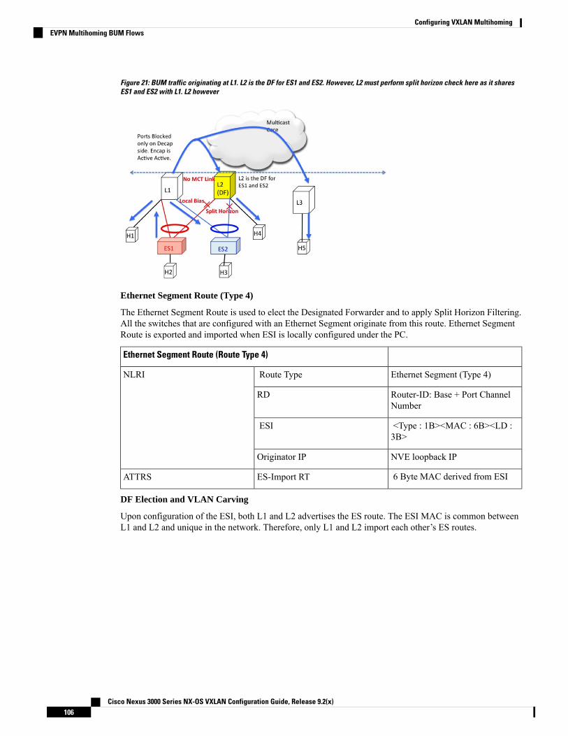
Figure 21: BUM traffic originating at L1. L2 is the DF for ES1 and ES2. However, L2 must perform split horizon check here as it sharesES1 and ES2 with L1. L2 however
Ethernet Segment Route (Type 4)
The Ethernet Segment Route is used to elect the Designated Forwarder and to apply Split Horizon Filtering.All the switches that are configured with an Ethernet Segment originate from this route. Ethernet SegmentRoute is exported and imported when ESI is locally configured under the PC.
Ethernet Segment Route (Route Type 4)
Ethernet Segment (Type 4)Route TypeNLRI
Router-ID: Base + Port ChannelNumber
RD
<Type : 1B><MAC : 6B><LD :3B>
ESI
NVE loopback IPOriginator IP
6 Byte MAC derived from ESIES-Import RTATTRS
DF Election and VLAN Carving
Upon configuration of the ESI, both L1 and L2 advertises the ES route. The ESI MAC is common betweenL1 and L2 and unique in the network. Therefore, only L1 and L2 import each other’s ES routes.
Cisco Nexus 3000 Series NX-OS VXLAN Configuration Guide, Release 9.2(x)106
Configuring VXLAN MultihomingEVPN Multihoming BUM Flows

Figure 22: If VLAN % count equals to ordinal, take up DF role.
Core and Site Failures for BUM Traffic
If the access link pertaining to ES1 fails at L1, L1 withdraws the ES route for ES1. This leads to a changetriggering re-compute the DF. Since L2 is the only TOR left in the Ordinal Table, it takes over DF role forall VLANs.
BGP EVPN multihoming on Cisco Nexus 3100 Series switches provides minimum operational and cablingexpenditure, provisioning simplicity, flow based load balancing, multi pathing, and fail-safe redundancy.
Configuring VLAN Consistency Checking
Overview of VLAN Consistency CheckingIn a typical multihoming deployment scenario, host 1 belonging to VLANX sends traffic to the access switchand then the access switch sends the traffic to both the uplinks towards VTEP1 and VTEP2. The access switchdoes not have the information about VLAN X configuration on VTEP1 and VTEP2. VLAN X configurationmismatch on VTEP1 or VTEP2 results in a partial traffic loss for host 1. VLAN consistency checking helpsto detect such configuration mismatch.
For VLAN consistency checking, CFSoIP is used. Cisco Fabric Services (CFS) provides a commoninfrastructure to exchange the data across the switches in the same network. CFS has the ability to discoverCFS capable switches in the network and to discover the feature capabilities in all the CFS capable switches.You can use CFS over IP (CFSoIP) to distribute and synchronize a configuration on one Cisco device or withall other Cisco devices in your network.
CFSoIP uses multicast to discover all the peers in the management IP network. For EVPNmultihoming VLANconsistency checking, it is recommended to override the default CFS multicast address with the cfs ipv4mcast-address <mcast address> CLI command. To enable CFSoIP, the cfs ipv4 distribute CLI commandshould be used.
When a trigger (for example, device booting up, VLAN configuration change, VLANs administrative statechange on the ethernet-segment port-channel) is issued on one of the multihoming peers, a broadcast request
Cisco Nexus 3000 Series NX-OS VXLAN Configuration Guide, Release 9.2(x)107
Configuring VXLAN MultihomingConfiguring VLAN Consistency Checking
with a snapshot of configured and administratively up VLANs for the ethernet-segment (ES) is sent to all theCFS peers.
When a broadcast request is received, all CFS peers sharing the same ES as the requestor respond with theirVLAN list (configured and administratively up VLAN list per ES). The VLAN consistency checking is runupon receiving a broadcast request or a response.
A 15 seconds timer is kicked off before sending a broadcast request. On receiving the broadcast request orresponse, the local VLAN list is compared with that of the ES peer. The VLANs that do not match aresuspended. Newly matched VLANs are no longer suspended.
VLAN consistency checking runs for the following events:
• Global VLAN configuration: Add, delete, shut, or no shut events.
Port channel VLAN configuration: Trunk allowed VLANs added or removed or access VLAN changed.
• CFS events: CFS peer added or deleted or CFSoIP configuration is removed.
• ES Peer Events: ES peer added or deleted.
The broadcast request is retransmitted if a response is not received. VLAN consistency checking fails to runif a response is not received after 3 retransmissions.
VLAN Consistency Checking Guidelines and LimitationsSee the following guidelines and limitations for VLAN consistency checking:
• The VLAN consistency checking uses CFSoIP. Out-of-band access through a management interface ismandatory on all multihoming switches in the network.
• It is recommended to override the default CFS multicast address with the CLI cfs ipv4 mcast-address<mcast address> command.
• The VLAN consistency check cannot detect a mismatch in switchport trunk native vlan configuration.
• CFSoIP and CFSoE should not be used in the same device.
• CFSoIP should not be used in devices that are not used for VLAN consistency checking.
• If CFSoIP is required in devices that do not participate in VLAN consistency checking, a differentmulticast group should be configured for devices that participate in VLAN consistency with the CLI cfsipv4 mcast-address <mcast address> command.
Displaying Show command Output for VLAN Consistency CheckingSee the following show commands output for VLAN consistency checking.
To list the CFS peers, use the sh cfs peers name nve CLI command.
switch# sh cfs peers name nve
Scope : Physical-ip-------------------------------------------------------------------------Switch WWN IP Address-------------------------------------------------------------------------20:00:f8:c2:88:23:19:47 172.31.202.228 [Local]
Cisco Nexus 3000 Series NX-OS VXLAN Configuration Guide, Release 9.2(x)108
Configuring VXLAN MultihomingVLAN Consistency Checking Guidelines and Limitations

Switch20:00:f8:c2:88:90:c6:21 172.31.201.172 [Not Merged]20:00:f8:c2:88:23:22:8f 172.31.203.38 [Not Merged]20:00:f8:c2:88:23:1d:e1 172.31.150.132 [Not Merged]20:00:f8:c2:88:23:1b:37 172.31.202.233 [Not Merged]20:00:f8:c2:88:23:05:1d 172.31.150.134 [Not Merged]
The show nve ethernet-segment command now displays the following details:
• The list of VLANs for which consistency check is failed.
• Remaining value (in seconds) of the global VLAN CC timer.
switch# sh nve ethernet-segmentESI Database----------------------------------------ESI: 03aa.aaaa.aaaa.aa00.0001,
Parent interface: port-channel2,ES State: UpPort-channel state: UpNVE Interface: nve1NVE State: UpHost Learning Mode: control-planeActive Vlans: 3001-3002DF Vlans: 3002Active VNIs: 30001-30002CC failed VLANs: 0-3000,3003-4095CC timer status: 10 seconds leftNumber of ES members: 2My ordinal: 0DF timer start time: 00:00:00Config State: config-appliedDF List: 201.1.1.1 202.1.1.1ES route added to L2RIB: TrueEAD routes added to L2RIB: True
See the following Syslog output:
switch(config)# 2017 Jan ?7 19:44:35 Switch %ETHPORT-3-IF_ERROR_VLANS_SUSPENDED: VLANs2999-3000 on Interface port-channel40 are being suspended.(Reason: SUCCESS)
After Fixing configuration2017 Jan ?7 19:50:55 Switch %ETHPORT-3-IF_ERROR_VLANS_REMOVED: VLANs 2999-3000 on Interfaceport-channel40 are removed from suspended state.
Configuring ESI ARP Suppression
Overview of ESI ARP SuppressionESI ARP suppression is an extension of already available ARP suppression solution in VXLAN-EVPN. Thisfeature is supported on top of ESI multihoming solution, that is on top of VXLAN-EVPN solution. ARP
Cisco Nexus 3000 Series NX-OS VXLAN Configuration Guide, Release 9.2(x)109
Configuring VXLAN MultihomingConfiguring ESI ARP Suppression

suppression is an optimization on top of BGP-EVPNmultihoming solution. ARP broadcast is one of the mostsignificant part of broadcast traffic in data centers. ARP suppression significantly cuts down on ARP broadcastin the data center.
ARP request from host is normally flooded in the VLAN. You can optimize flooding by maintaining an ARPcache locally on the access switch. ARP cache is maintained by the ARP module. ARP cache is populated bysnooping all the ARP packets from the access or server side. Initial ARP requests are broadcasted to all thesites. Subsequent ARP requests are suppressed at the first hop leaf and they are answered locally. In this way,the ARP traffic across overlay can be significantly reduced.
ARP suppression is only supported with BGP-EVPN (distributed gateway).
ESI ARP suppression is a per-VNI (L2-VNI) feature. ESI ARP suppression is supported in both L2 (no SVI)and L3 modes. Beginning with Cisco NX-OS Release 7.0(3)I7(1), only L3 mode is supported.
The ESI ARP suppression cache is built by:
• Snooping all ARP packets and populating ARP cache with the source IP and MAC bindings from therequest.
• Learning IP-host or MAC-address information through BGP EVPN MAC-IP route advertisement.
Upon receiving the ARP request, the local cache is checked to see if the response can be locally generated.If the cache lookup fails, the ARP request can be flooded. This helps with the detection of the silent hosts.
Limitations for ESI ARP SuppressionSee the following limitations for ESI ARP suppression:
• ESI multihoming solution is supported only on Cisco Nexus 3100 Series switches.
• ESI ARP suppression is only supported in L3 [SVI] mode.
• ESI ARP suppression cache limit is 64K that includes both local and remote entries.
Configuring ESI ARP SuppressionFor ARP suppression VACLs to work, configure the TCAM carving using the hardware access-list tcamregion arp-ether 256 CLI command.
Interface nve1no shutdownsource-interface loopback1host-reachability protocol bgpmember vni 10000
suppress-arpmcast-group 224.1.1.10
Displaying Show Commands for ESI ARP SuppressionSee the following Show commands output for ESI ARP suppression:
switch# show ip arp suppression-cache ?detail Show details
Cisco Nexus 3000 Series NX-OS VXLAN Configuration Guide, Release 9.2(x)110
Configuring VXLAN MultihomingLimitations for ESI ARP Suppression

local Show local entriesremote Show remote entriesstatistics Show statisticssummary Show summaryvlan L2vlan
switch# show ip arp suppression-cache local
Flags: + - Adjacencies synced via CFSoEL - Local AdjacencyR - Remote AdjacencyL2 - Learnt over L2 interfacePS - Added via L2RIB, Peer SyncRO - Dervied from L2RIB Peer Sync Entry
Ip Address Age Mac Address Vlan Physical-ifindex Flags RemoteVtep Addrs
61.1.1.20 00:07:54 0000.0610.0020 610 port-channel20 L61.1.1.30 00:07:54 0000.0610.0030 610 port-channel2 L[PS RO]61.1.1.10 00:07:54 0000.0610.0010 610 Ethernet1/96 L
switch# show ip arp suppression-cache remoteFlags: + - Adjacencies synced via CFSoE
L - Local AdjacencyR - Remote AdjacencyL2 - Learnt over L2 interfacePS - Added via L2RIB, Peer SyncRO - Dervied from L2RIB Peer Sync EntryIp Address Age Mac Address Vlan Physical-ifindex Flags
Remote Vtep Addrs61.1.1.40 00:48:37 0000.0610.0040 610 (null) RVTEP1, VTEP2.. VTEPn
switch# show ip arp suppression-cache detailFlags: + - Adjacencies synced via CFSoEL - Local AdjacencyR - Remote AdjacencyL2 - Learnt over L2 interfacePS - Added via L2RIB, Peer SyncRO - Derived from L2RIB Peer Sync Entry
Ip Address Age Mac Address Vlan Physical-ifindex FlagsRemote Vtep Addrs
61.1.1.20 00:00:07 0000.0610.0020 610 port-channel20 L61.1.1.30 00:00:07 0000.0610.0030 610 port-channel2 L[PS RO]61.1.1.10 00:00:07 0000.0610.0010 610 Ethernet1/96 L61.1.1.40 00:00:07 0000.0610.0040 610 (null) RVTEP1, VTEP2.. VTEPn
switch# show ip arp suppression-cache summaryIP ARP suppression-cache SummaryRemote :1Local :3Total :4switch# show ip arp suppression-cache statisticsARP packet statistics for suppression-cacheSuppressed:Total 0, Requests 0, Requests on L2 0, Gratuitous 0, Gratuitous on L2 0Forwarded :Total: 364
Cisco Nexus 3000 Series NX-OS VXLAN Configuration Guide, Release 9.2(x)111
Configuring VXLAN MultihomingDisplaying Show Commands for ESI ARP Suppression

L3 mode : Requests 364, Replies 0Request on core port 364, Reply on core port 0
Dropped 0L2 mode : Requests 0, Replies 0
Request on core port 0, Reply on core port 0Dropped 0
Received:Total: 3016L3 mode: Requests 376, Replies 2640Local Request 12, Local Responses 2640
Gratuitous 0, Dropped 0L2 mode : Requests 0, Replies 0
Gratuitous 0, Dropped 0
switch# sh ip arp multihoming-statistics vrf allARP Multihoming statistics for all contextsRoute Stats============Receieved ADD from L2RIB :1756 | 1756:Processed ADD from L2RIB Receieved DEL fromL2RIB :88 | 87:Processed DEL from L2RIB Receieved PC shut from L2RIB :0 |1755:Processed PC shut from L2RIB Receieved remote UPD from L2RIB :5004 | 0:Processed remoteUPD from L2RIBERRORS=======Multihoming ADD error invalid flag :0Multihoming DEL error invalid flag :0Multihoming ADD error invalid current state:0Multihoming DEL error invalid current state:0Peer sync DEL error MAC mismatch :0Peer sync DEL error second delete :0Peer sync DEL error deleteing TL route :0True local DEL error deleteing PS RO route :0
switch#
Cisco Nexus 3000 Series NX-OS VXLAN Configuration Guide, Release 9.2(x)112
Configuring VXLAN MultihomingDisplaying Show Commands for ESI ARP Suppression

C H A P T E R 7Configuring IPv6 Across a VXLAN EVPN Fabric
This chapter contains the following sections:
• Overview of IPv6 Across a VXLAN EVPN Fabric, on page 113• Configuring IPv6 Across a VXLAN EVPN Fabric Example, on page 113• Show Command Examples, on page 117
Overview of IPv6 Across a VXLAN EVPN FabricThis section provides an example configuration that enables IPv6 in the overlay of a VXLAN EVPN fabric.
Cisco Nexus 3500 Series switches do not support IPv6 Across VXLAN EVPN on Cisco NX-OS Release7.0(3)I7(2) and the previous releases.
The VXLAN encapsulation mechanism encapsulates the IPv6 packets in the overlay as IPv4 UDP packetsand uses IPv4 routing to transport the VXLAN encapsulated traffic.
To enable IPv6 across a VXLAN EVPN fabric, the IPv6 address family is included in VRF, BGP, and EVPN.IPv6 routes are initiated in the tenant VRF IPv6 unicast address-family on a VTEP and are advertised in theVXLAN fabric through the L2VPN EVPN address family as EVPN route-type 2 or 5.
These routes are advertised as EVPN routes on the SPINE.Note
Configuring IPv6 Across a VXLAN EVPN Fabric ExampleTopology for the example:
Cisco Nexus 3000 Series NX-OS VXLAN Configuration Guide, Release 9.2(x)113
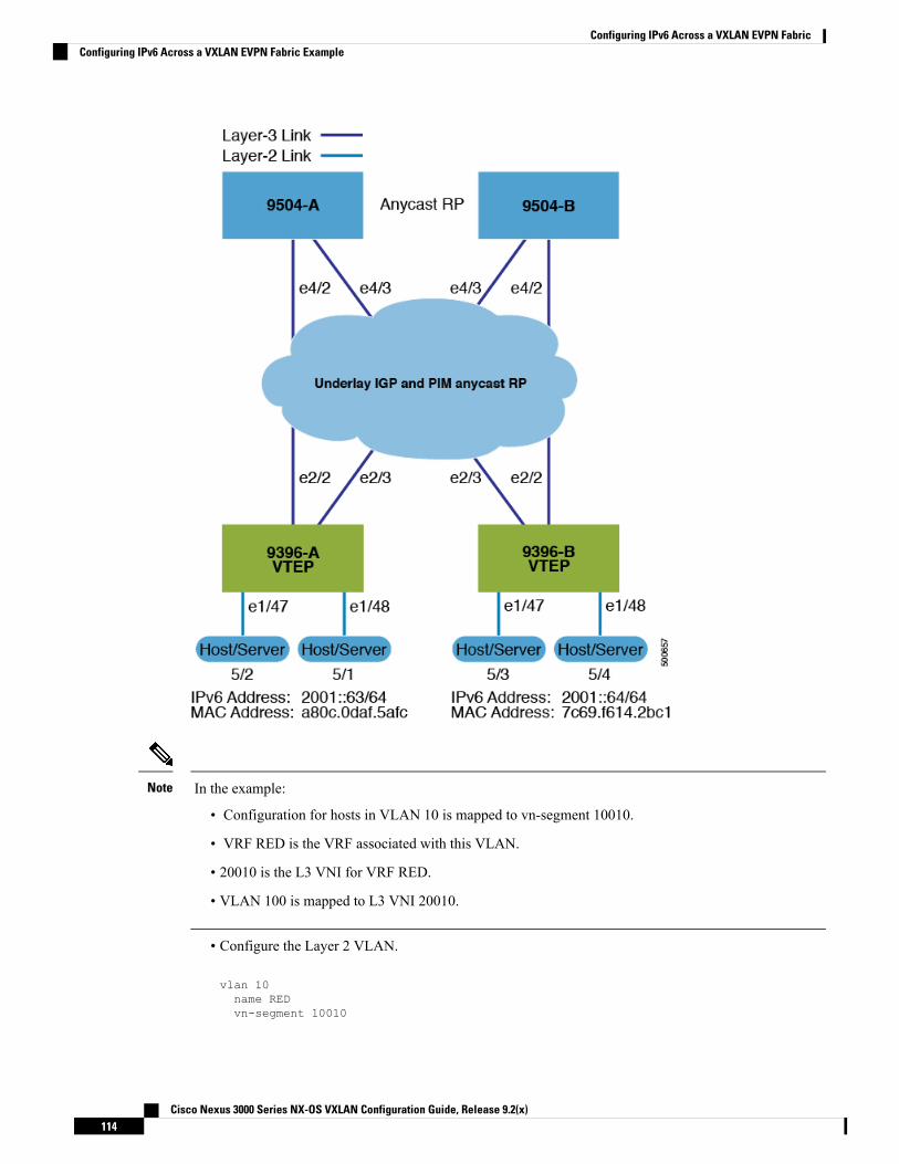
In the example:
• Configuration for hosts in VLAN 10 is mapped to vn-segment 10010.
• VRF RED is the VRF associated with this VLAN.
• 20010 is the L3 VNI for VRF RED.
• VLAN 100 is mapped to L3 VNI 20010.
Note
• Configure the Layer 2 VLAN.
vlan 10name REDvn-segment 10010
Cisco Nexus 3000 Series NX-OS VXLAN Configuration Guide, Release 9.2(x)114
Configuring IPv6 Across a VXLAN EVPN FabricConfiguring IPv6 Across a VXLAN EVPN Fabric Example
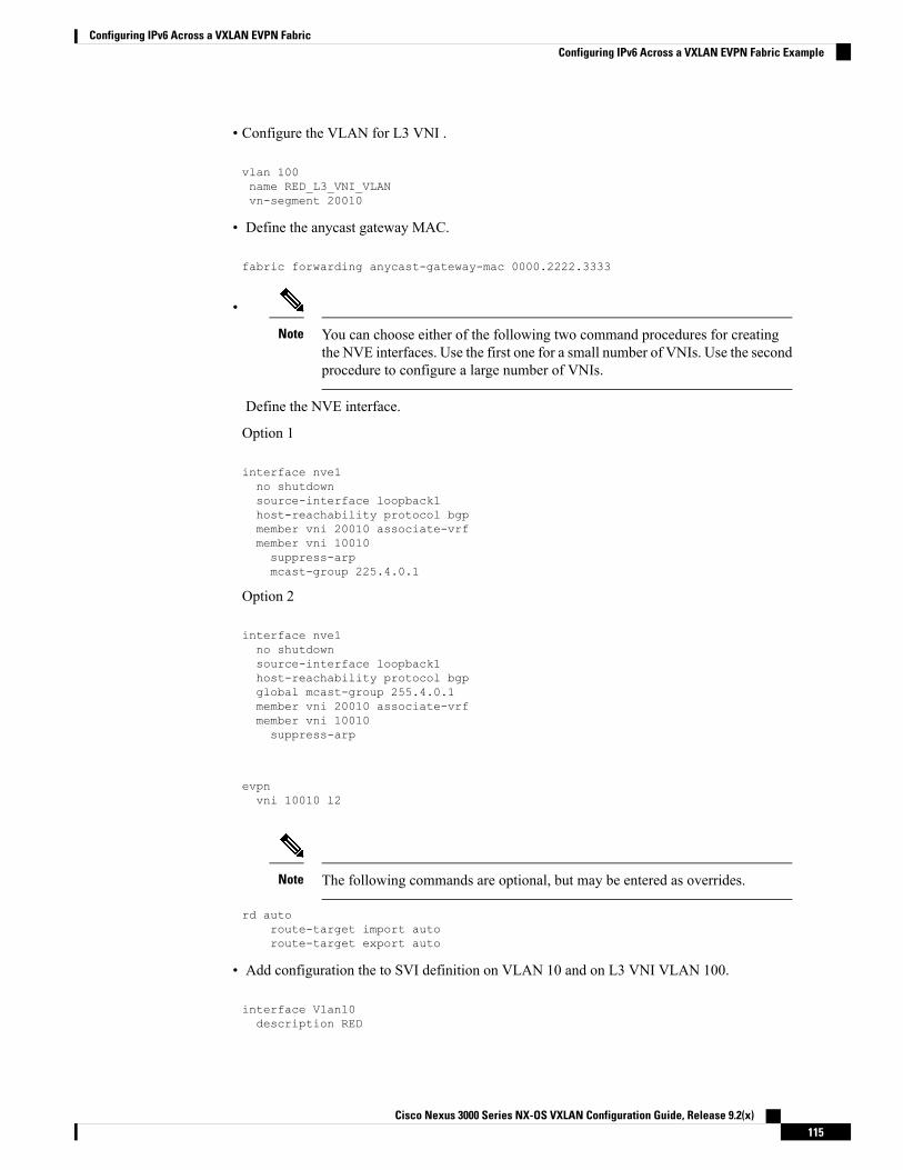
• Configure the VLAN for L3 VNI .
vlan 100name RED_L3_VNI_VLANvn-segment 20010
• Define the anycast gateway MAC.
fabric forwarding anycast-gateway-mac 0000.2222.3333
•
You can choose either of the following two command procedures for creatingthe NVE interfaces. Use the first one for a small number of VNIs. Use the secondprocedure to configure a large number of VNIs.
Note
Define the NVE interface.
Option 1
interface nve1no shutdownsource-interface loopback1host-reachability protocol bgpmember vni 20010 associate-vrfmember vni 10010suppress-arpmcast-group 225.4.0.1
Option 2
interface nve1no shutdownsource-interface loopback1host-reachability protocol bgpglobal mcast-group 255.4.0.1member vni 20010 associate-vrfmember vni 10010suppress-arp
evpnvni 10010 l2
The following commands are optional, but may be entered as overrides.Note
rd autoroute-target import autoroute-target export auto
• Add configuration the to SVI definition on VLAN 10 and on L3 VNI VLAN 100.
interface Vlan10description RED
Cisco Nexus 3000 Series NX-OS VXLAN Configuration Guide, Release 9.2(x)115
Configuring IPv6 Across a VXLAN EVPN FabricConfiguring IPv6 Across a VXLAN EVPN Fabric Example

no shutdownvrf member REDno ip redirectsip address 10.1.1.1/24ipv6 address 2001::1/64fabric forwarding mode anycast-gateway
• Configure SVI definition for VLAN 100.
interface Vlan100description RED_L3_VNI_VLANno shutdownvrf member REDip forwardipv6 address use-link-local-only
The IPv6 address use-link-local-only serves the same purpose as IP FORWARDfor IPv4. It enables the switch to perform an IP based lookup even when theinterface VLAN has no IP address defined under it.
Note
• Add configuration to the VRF definition.
vrf context REDvni 20010rd auto
The following commands are automatically configured unless one or more areentered as overrides.
Note
rd autoaddress-family ipv4 unicastroute-target both autoroute-target both auto evpn
address-family ipv6 unicastroute-target both autoroute-target both auto evpn
evpnvni 10010 l2
The following commands are automatically configured unless one or more areentered as overrides.
Note
rd autoroute-target import autoroute-target export auto
• Add configuration to the VRF definition under BGP.
Cisco Nexus 3000 Series NX-OS VXLAN Configuration Guide, Release 9.2(x)116
Configuring IPv6 Across a VXLAN EVPN FabricConfiguring IPv6 Across a VXLAN EVPN Fabric Example

router bgp 65000vrf REDaddress-family ipv4 unicastadvertise l2vpn evpn
address-family ipv6 unicastadvertise l2vpn evpn
If VTEPs are configured to operate as VPC peers, the following configuration is a best practice that shouldbe included under the VPC domain on both switches.
vpc domain 1ipv6 nd synchronize
Note
Show Command ExamplesThe following are examples of verifying IPv6 advertisement over VXLAN EVPN:
• Display ND information for the connected server.
9396-B_VTEP# show ipv6 neighbor vrf RED
Flags: # - Adjacencies Throttled for GleanG - Adjacencies of vPC peer with G/W bitR - Adjacencies learnt remotely
IPv6 Adjacency Table for VRF REDTotal number of entries: 2Address Age MAC Address Pref Source Interface2001::64 00:00:26 7c69.f614.2bc1 50 icmpv6 Vlan10fe80::7e69:f6ff:fe14:2bc1
00:01:13 7c69.f614.2bc1 50 icmpv6 Vlan10
• Check the L2ROUTE and ensure the MAC-IP was learned.
9396-B_VTEP# show l2route evpn mac-ip evi 10 host-ip 2001::64Mac Address Prod Host IP Next Hop (s)-------------- ---- --------------------------------------- ---------------7c69.f614.2bc1 HMM 2001::64 N/A
MAC-IP table is populated only when the end server sends a neighbor solicitationmessage (ARP in case of IPv4).
Note
• Verify the route is present locally in the BGP table.
9396-B_VTEP# show bgp l2vpn evpn 2001::64BGP routing table information for VRF default, address family L2VPN EVPNRoute Distinguisher: 198.19.0.15:34180 (L2VNI 10010)BGP routing table entry for [2]:[0]:[0]:[48]:[7c69.f614.2bc1]:[128]:[2001::64]/368,version 678
Cisco Nexus 3000 Series NX-OS VXLAN Configuration Guide, Release 9.2(x)117
Configuring IPv6 Across a VXLAN EVPN FabricShow Command Examples

Paths: (1 available, best #1)Flags: (0x00010a) on xmit-list, is not in l2rib/evpn
Advertised path-id 1Path type: local, path is valid, is best path, no labeled nexthopAS-Path: NONE, path locally originated198.19.0.15 (metric 0) from 0.0.0.0 (198.19.0.15)Origin IGP, MED not set, localpref 100, weight 32768Received label 10010 20010Extcommunity: RT:64567:10010 RT:64567:20010
Path-id 1 advertised to peers:198.19.0.3198.19.0.4
• Verify the route is present in the remote VTEP 9396-A-VTEP BGP table.
9396-A-VTEP# show bgp l2vpn evpn 2001::64BGP routing table information for VRF default, address family L2VPN EVPNRoute Distinguisher: 198.19.0.14:34180 (L2VNI 10010)BGP routing table entry for [2]:[0]:[0]:[48]:[7c69.f614.2bc1]:[128]:[2001::64]/368,version 305Paths: (1 available, best #1)Flags: (0x00021a) on xmit-list, is in l2rib/evpn, is not in HW,
Advertised path-id 1Path type: internal, path is valid, is best path, no labeled nexthop
Imported from198.19.0.15:34180:[2]:[0]:[0]:[48]:[7c69.f614.2bc1]:[128]:[2001::64]/240AS-Path: NONE, path sourced internal to AS198.19.0.15 (metric 81) from 198.19.0.3 (198.19.0.3)Origin IGP, MED not set, localpref 100, weight 0Received label 10010 20010Extcommunity: RT:64567:10010 RT:64567:20010 ENCAP:8 Router MAC:5087.89a1.a52fOriginator: 198.19.0.15 Cluster list: 198.19.0.3
• Check the L2ROUTE and ensure that the MAC-IP was learned on the remote VTEP - 9396-A-VTEP.
rswV1leaf14# show l2route evpn mac-ip evi 1413 host-ip 2001::64Mac Address Prod Host IP Next Hop (s)-------------- ---- --------------------------------------- --------------7c69.f614.2bc1 BGP 2001::64 198.19.0.15
Cisco Nexus 3000 Series NX-OS VXLAN Configuration Guide, Release 9.2(x)118
Configuring IPv6 Across a VXLAN EVPN FabricShow Command Examples

I N D E X
A
address-family ipv4 unicast 36, 39address-family ipv6 unicast 36, 39address-family l2vpn evpn 39, 40, 41advertise 39associate- vrf 34
B
bud node 6
C
configuring an NVE interface 19configuring rendezvous points 15Configuring Replication 19configuring RPs 15configuring unicast routing protocol 17configuring VXLAN UDP port 18creating an NVE interface 19Creating VXLAN UDP port 18
E
enabling feature nv overlay 16enabling PIM 14enabling VLAN to vn-segment mapping 16evpn 39
F
fabric forwarding 34fabric forwarding anycast-gateway-mac 38fabric forwarding mode anycast-gateway 38feature nv overlay 35feature vn-segment 35
H
hardware access-list tcam region arp-ether double-wide 30, 41host-reachability protocol bgp 34, 38
I
ingress replication 20interface 38interface nve 1 41ip address 37
L
layer 2 mechanism for broadcast, unknown unicast, and multicasttraffic 5
layer 2 mechanism for learnt unicast traffic 5
M
mcast-group 38member vni 34, 38, 41
N
neighbor 39, 41no feature nv overlay 42no feature vn-segment-vlan-based 42no nv overlay evpn 42nv overlay evpn 34, 35
R
rd auto 36, 40retain route-target all 40route-map permitall out 41route-map permitall permit 10 40route-target both auto 36route-target both auto evpn 36, 37route-target export auto 40route-target import auto 40router bgp 34, 38, 40router-id 38
S
send-community extended 39, 41set ip next-hop unchanged 40show bgp l2vpn evpn 34, 45, 69
Cisco Nexus 3000 Series NX-OS VXLAN Configuration Guide, Release 9.2(x)IN-1

show bgp l2vpn evpn summary 34, 68show ip arp suppression-cache 45show ip arp suppression-cache detail 68show l2route evpn fl all 45show l2route evpn imet all 45show l2route evpn mac 45show l2route evpn mac all 69show l2route evpn mac-ip all 45, 70show l2route evpn mac-ip all detail 45show l2route topology 45show nve peers 68show nve vni 34, 68show nve vni summary 34show nve vrf 45show vxlan interface 45, 68show vxlan interface | count 45source-interface config 29
source-interface hold-down-time 29spanning-tree bpdufilter enable 21suppress-arp 34, 41suppress-mac-route 35switchport access vlan 21switchport mode dot1q-tunnel 21
V
vlan 36, 37VLAN to VXLAN VNI mapping 17vn-segment 36, 37vni 36, 37, 39VNI to multicast group mapping 20vrf 39vrf context 34, 36, 37vrf member 37
Cisco Nexus 3000 Series NX-OS VXLAN Configuration Guide, Release 9.2(x)IN-2
INDEX