Cisco ME 1200 Series Carrier Ethernet Access Devices ... · 10/100/1000 B-1 SFP Module Connectors...
44
Cisco Systems, Inc. www.cisco.com Cisco has more than 200 offices worldwide. Addresses, phone numbers, and fax numbers are listed on the Cisco website at www.cisco.com/go/offices. Cisco ME 1200 Series Carrier Ethernet Access Devices Hardware Installation Guide June 2017 Text Part Number: OL-31962-04
Transcript of Cisco ME 1200 Series Carrier Ethernet Access Devices ... · 10/100/1000 B-1 SFP Module Connectors...
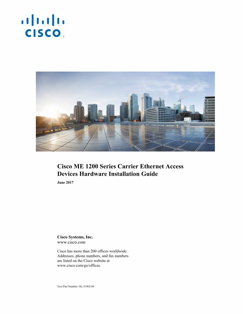
Cisco ME 1200 Series Carrier Ethernet Access Devices Hardware Installation GuideJune 2017
Cisco Systems, Inc.www.cisco.com
Cisco has more than 200 offices worldwide. Addresses, phone numbers, and fax numbers are listed on the Cisco website at www.cisco.com/go/offices.
Text Part Number: OL-31962-04

THE SPECIFICATIONS AND INFORMATION REGARDING THE PRODUCTS IN THIS MANUAL ARE SUBJECT TO CHANGE WITHOUT NOTICE. ALL STATEMENTS, INFORMATION, AND RECOMMENDATIONS IN THIS MANUAL ARE BELIEVED TO BE ACCURATE BUT ARE PRESENTED WITHOUT WARRANTY OF ANY KIND, EXPRESS OR IMPLIED. USERS MUST TAKE FULL RESPONSIBILITY FOR THEIR APPLICATION OF ANY PRODUCTS.
THE SOFTWARE LICENSE AND LIMITED WARRANTY FOR THE ACCOMPANYING PRODUCT ARE SET FORTH IN THE INFORMATION PACKET THAT SHIPPED WITH THE PRODUCT AND ARE INCORPORATED HEREIN BY THIS REFERENCE. IF YOU ARE UNABLE TO LOCATE THE SOFTWARE LICENSE OR LIMITED WARRANTY, CONTACT YOUR CISCO REPRESENTATIVE FOR A COPY.
The following information is for FCC compliance of Class A devices: This equipment has been tested and found to comply with the limits for a Class A digital device, pursuant to part 15 of the FCC rules. These limits are designed to provide reasonable protection against harmful interference when the equipment is operated in a commercial environment. This equipment generates, uses, and can radiate radio-frequency energy and, if not installed and used in accordance with the instruction manual, may cause harmful interference to radio communications. Operation of this equipment in a residential area is likely to cause harmful interference, in which case users will be required to correct the interference at their own expense.
The following information is for FCC compliance of Class B devices: This equipment has been tested and found to comply with the limits for a Class B digital device, pursuant to part 15 of the FCC rules. These limits are designed to provide reasonable protection against harmful interference in a residential installation. This equipment generates, uses and can radiate radio frequency energy and, if not installed and used in accordance with the instructions, may cause harmful interference to radio communications. However, there is no guarantee that interference will not occur in a particular installation. If the equipment causes interference to radio or television reception, which can be determined by turning the equipment off and on, users are encouraged to try to correct the interference by using one or more of the following measures:
• Reorient or relocate the receiving antenna.
• Increase the separation between the equipment and receiver.
• Connect the equipment into an outlet on a circuit different from that to which the receiver is connected.
• Consult the dealer or an experienced radio/TV technician for help.
Modifications to this product not authorized by Cisco could void the FCC approval and negate your authority to operate the product.
The Cisco implementation of TCP header compression is an adaptation of a program developed by the University of California, Berkeley (UCB) as part of UCB’s public domain version of the UNIX operating system. All rights reserved. Copyright © 1981, Regents of the University of California.
NOTWITHSTANDING ANY OTHER WARRANTY HEREIN, ALL DOCUMENT FILES AND SOFTWARE OF THESE SUPPLIERS ARE PROVIDED “AS IS” WITH ALL FAULTS. CISCO AND THE ABOVE-NAMED SUPPLIERS DISCLAIM ALL WARRANTIES, EXPRESSED OR IMPLIED, INCLUDING, WITHOUT LIMITATION, THOSE OF MERCHANTABILITY, FITNESS FOR A PARTICULAR PURPOSE AND NONINFRINGEMENT OR ARISING FROM A COURSE OF DEALING, USAGE, OR TRADE PRACTICE.
IN NO EVENT SHALL CISCO OR ITS SUPPLIERS BE LIABLE FOR ANY INDIRECT, SPECIAL, CONSEQUENTIAL, OR INCIDENTAL DAMAGES, INCLUDING, WITHOUT LIMITATION, LOST PROFITS OR LOSS OR DAMAGE TO DATA ARISING OUT OF THE USE OR INABILITY TO USE THIS MANUAL, EVEN IF CISCO OR ITS SUPPLIERS HAVE BEEN ADVISED OF THE POSSIBILITY OF SUCH DAMAGES.
Cisco and the Cisco logo are trademarks or registered trademarks of Cisco and/or its affiliates in the U.S. and other countries. To view a list of Cisco trademarks, go to this URL: www.cisco.com/go/trademarks. Third-party trademarks mentioned are the property of their respective owners. The use of the word partner does not imply a partnership relationship between Cisco and any other company. (1110R)
Any Internet Protocol (IP) addresses and phone numbers used in this document are not intended to be actual addresses and phone numbers. Any examples, command display output, network topology diagrams, and other figures included in the document are shown for illustrative purposes only. Any use of actual IP addresses or phone numbers in illustrative content is unintentional and coincidental.
© 2014-2017 Cisco Systems, Inc. All rights reserved.
Cisco ME
OL-31962-04
C O N T E N T S
Audience 1-3
Purpose 1-3
Related Publications 1-4
C H A P T E R 1 Setting Up the Switch 1-1
Switch Models 1-1
Front Panel 1-2
Console Port 1-2
10/100/1000 Gigabit Ethernet Ports 1-3
SFP Modules 1-3
LEDs 1-4
System LED 1-5
Port LEDs 1-5
Rear Panel 1-5
Management Options 1-6
Management Option 1 1-6
Management Option 2 1-6
Management Option 3 1-6
Network Configurations 1-7
C H A P T E R 2 Warnings 2-1
Installation Guidelines 2-3
Verifying Switch Operation 2-4
Installation the Switch 2-4
Rack-Mounting 2-4
Attaching Brackets to the Switch 2-4
Attaching Brackets to the Switch 2-6
Mounting in a Rack 2-6
Mounting the Switch using 19-inch, 23-inch, and ETSI Brackets 2-7
Mounting the Switch on a Wall 2-7
Desktop Mounting 2-8
Installing and Removing SFP Modules 2-9
Installing SFP Modules 2-9
1 1200 Series Carrier Ethernet Access Devices Hardware Installation Guide
Removing SFP Modules 2-11
Connecting to the 10/100/1000 Ports 2-11
Initial Configuration 2-12
Scenario 1 - Zero Touch Provisioning 2-12
Scenario 2 - Accessing Cisco ME1200 NID Through ME3600 UPE NID Controller Mode 2-12
C H A P T E R 3 Installing an AC Power Cord Retainer Clip 3-1
Installing an AC Power Cord 3-2
Installing an AC-to-DC Power Adapter 3-2
Wiring the DC Input Power Source 3-3
Grounding the Switch 3-4
C H A P T E R 4 Diagnosing Problems 4-1
Switch Performance 4-1
Speed, Duplex, and Auto-negotiation 4-1
Auto-negotiation and NICs 4-2
Cabling Distance 4-2
Finding the Switch Serial Number 4-2
Technical Specifications A-1
Environmental and Technical Specifications for the Switch A-1
Environmental and Technical Specifications for the Power Adapter A-2
Connector and Cable Specifications B-1
10/100/1000 B-1
SFP Module Connectors B-1
SFP Module Cabling B-2
Cable Pin-outs B-4
Console Port Adapter Pin-outs B-5
2Cisco ME 1200 Series Carrier Ethernet Access Devices Hardware Installation Guide
OL-31962-04

Preface
Audience This guide is for the person installing the Cisco ME 1200 Series Carrier Ethernet Access Devices, also known as Cisco ME 1200 NID.
PurposeThis guide describes the hardware features of the Cisco ME 1200 NID. It describes the physical and performance characteristics of the switch, explains how to install it, and provides troubleshooting information.
This guide does not describe system messages that you might receive or how to configure your switch. For more information, see the switch Cisco NID Controller Guide on Cisco.com at:
http://www.cisco.com/c/en/us/support/switches/me-1200-series-carrier-ethernet-access-devices/tsd-products-support-general-information.html
Note Means reader take note. Notes contain helpful suggestions or references to materials not contained in this manual.
Caution Means reader be careful. In this situation, you might do something that could result in equipment damage or loss of data.
3Cisco ME 1200 Series Carrier Ethernet Access Devices Hardware Installation Guide
OL-31962-04

Related Publications
The safety warnings for this product are translated into several languages in the Cisco Regulatory Compliance and Safety Information for Cisco ME 1200 Series Carrier Ethernet Access Devices on Cisco.com. The EMC regulatory statements are also included in that guide.
Related PublicationsThese documents provide information about the switches and are available from this Cisco.com site:
http://www.cisco.com/c/en/us/support/switches/me-1200-series-carrier-ethernet-access-devices/tsd-products-support-general-information.html
• Release Notes for the Cisco ME 1200 Series Carrier Ethernet Access Devices
Note Before installing, configuring, or upgrading the switch, see the release notes on Cisco.com for the latest information.
• Cisco ME 1200 Series Carrier Ethernet Access Devices Software Cisco NID Controller Guide
• Cisco Regulatory Compliance and Safety Information for Cisco ME 1200 Series Carrier EthernetAccess Devices
Obtaining Documentation and Submitting a Service RequestFor information on obtaining documentation, using the Cisco Bug Search Tool (BST), submitting a service request, and gathering additional information, see What’s New in Cisco Product Documentation at: http://www.cisco.com/en/US/docs/general/whatsnew/whatsnew.html.
Subscribe to What’s New in Cisco Product Documentation, which lists all new and revised Cisco technical documentation, as an RSS feed and deliver content directly to your desktop using a reader application. The RSS feeds are a free service.
Warning IMPORTANT SAFETY INSTRUCTIONS
This warning symbol means danger. You are in a situation that could cause bodily injury. Before you work on any equipment, be aware of the hazards involved with electrical circuitry and be familiar with standard practices for preventing accidents. Use the statement number provided at the end of each warning to locate its translation in the translated safety warnings that accompanied this device. Statement 1071
SAVE THESE INSTRUCTIONS
4Cisco ME 1200 Series Carrier Ethernet Access Devices Hardware Installation Guide
OL-31962-04

Cisco ME 1200 Series Carrier Ether
OL-31962-04
C H A P T E R 1
Product OverviewThe Cisco ME1200 NID Series of product is built and optimized for the Gigabit Ethernet Demarcation. It provides a standard based demarcation as defined by the MEF ELINE and ELAN services with advanced clocking and Quality of Services. This chapter provides a functional overview of the Cisco ME1200 NID.
• Setting Up the Switch, page 1-1
• Switch Models, page 1-1
• Front Panel, page 1-2
• Rear Panel, page 1-6
• Management Options, page 1-6
Setting Up the SwitchThis document covers switch management options, basic rack-mounting procedures, port and module connections, power connection procedures, and troubleshooting.
Switch ModelsThe Cisco ME1200 NID switches have fixed AC and DC power options. Each switch has 4 1GE SFP (Small Form factor Pluggable) ports and two RJ-45 copper Ethernet ports. All the variants support power redundancy using an external AC-DC power adapter.
Table 1-1 Cisco ME1200 NID Model
Switch Model Description
ME1200-4S-A AC power input: Between 100 and 240VAC12VDC adapter (optional)
ME1200-4S-D DC power input: -20.5 to -72 VDC12VDC adapter (optional)
1-1net Access Devices Hardware Installation Guide

Chapter 1 Product OverviewFront Panel
Front Panel
Figure 1-1 Cisco ME1200-4S-A Front Panel
Figure 1-2 Cisco ME1200-4S-D Front Panel
Console Port
The console port is used in display-only mode to output debug information. Console operation is not supported.The serial port’s configuration requirements are as follows:
• Default Baud rate—115,200 bps
• Parity—None
• Stop bit—One
• Data bits—8
• Flow control—none
1 AC 100V to 240V Power input 4 Console port
2 DC 12 VDC Power input 5 10/100/1000Base-T RJ-45 Port
3 RESET/ZTP 6 100Base-FX/1000Base-X SFP Fiber Port
1 DC -20.5V to -72V Power input 4 Console port
2 DC 12 VDC Power input 5 10/100/1000Base-T RJ-45 Port
3 RESET/ZTP 6 100Base-FX/1000Base-X SFP Fiber Port
1-2Cisco ME 1200 Series Carrier Ethernet Access Devices Hardware Installation Guide
OL-31962-04
Chapter 1 Product OverviewFront Panel
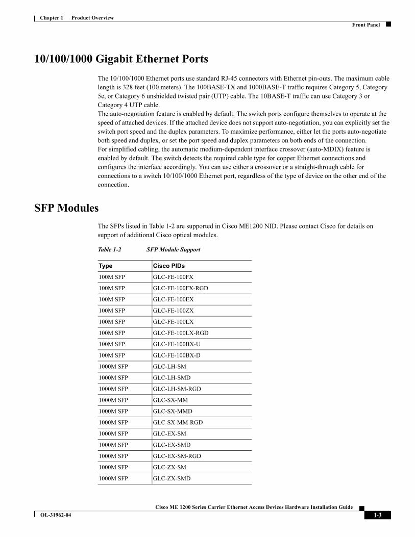
10/100/1000 Gigabit Ethernet Ports
The 10/100/1000 Ethernet ports use standard RJ-45 connectors with Ethernet pin-outs. The maximum cable length is 328 feet (100 meters). The 100BASE-TX and 1000BASE-T traffic requires Category 5, Category 5e, or Category 6 unshielded twisted pair (UTP) cable. The 10BASE-T traffic can use Category 3 or Category 4 UTP cable.The auto-negotiation feature is enabled by default. The switch ports configure themselves to operate at the speed of attached devices. If the attached device does not support auto-negotiation, you can explicitly set the switch port speed and the duplex parameters. To maximize performance, either let the ports auto-negotiate both speed and duplex, or set the port speed and duplex parameters on both ends of the connection.For simplified cabling, the automatic medium-dependent interface crossover (auto-MDIX) feature is enabled by default. The switch detects the required cable type for copper Ethernet connections and configures the interface accordingly. You can use either a crossover or a straight-through cable for connections to a switch 10/100/1000 Ethernet port, regardless of the type of device on the other end of the connection.
SFP Modules
The SFPs listed in Table 1-2 are supported in Cisco ME1200 NID. Please contact Cisco for details on support of additional Cisco optical modules.
Table 1-2 SFP Module Support
Type Cisco PIDs
100M SFP GLC-FE-100FX
100M SFP GLC-FE-100FX-RGD
100M SFP GLC-FE-100EX
100M SFP GLC-FE-100ZX
100M SFP GLC-FE-100LX
100M SFP GLC-FE-100LX-RGD
100M SFP GLC-FE-100BX-U
100M SFP GLC-FE-100BX-D
1000M SFP GLC-LH-SM
1000M SFP GLC-LH-SMD
1000M SFP GLC-LH-SM-RGD
1000M SFP GLC-SX-MM
1000M SFP GLC-SX-MMD
1000M SFP GLC-SX-MM-RGD
1000M SFP GLC-EX-SM
1000M SFP GLC-EX-SMD
1000M SFP GLC-EX-SM-RGD
1000M SFP GLC-ZX-SM
1000M SFP GLC-ZX-SMD
1-3Cisco ME 1200 Series Carrier Ethernet Access Devices Hardware Installation Guide
OL-31962-04

Chapter 1 Product OverviewFront Panel
LEDs
Figure 1-3 Cisco ME1200-4S-A and ME1200-4S-D Switch LEDs
1000M SFP GLC-ZX-SM-RGD
1000M SFP GLC-T1
1000M SFP CWDM-SFP-xxxx (8 colors)
1000M SFP GLC-BX-U
1000M SFP GLC-BX-D
1000M SFP SFP-GE-L
1000M SFP SFP-GE-S
1000M SFP SFP-GE-Z
1000M SFP SFP-GE-T
1000M SFP GLC-TE
1000M SFP DWDM-SFP-xxxx (40 wavelengths)
1. The system can support a lower operating ambienttemperature of -5oC with GLC-T. However, cold bootwith this module is supported only from 0oC.
Table 1-2 SFP Module Support
1 SYS (system) LED 3 Port LED (SFP)
2 Port LED (RJ-45)
1-4Cisco ME 1200 Series Carrier Ethernet Access Devices Hardware Installation Guide
OL-31962-04

Chapter 1 Product OverviewFront Panel
System LED
Port LEDs
Each port has two LEDs. These port LEDs display information about the individual ports.
Table 1-3 System LED
Function Color state Description
System Status
Off No Power
Solid Green System Healthy (POST in progress/normal operation)
Alternating Green/Off
ZTP downloading
Alternating Red/Off ZTP failed
Alternating Amber/Off
ZTP configuring
Solid Red Software error
Solid Amber System healthy, working with redundant PSU
Alternating Green/Amber
POST in progress
Table 1-4 Port LEDs
Color Port Status
Green RJ-45/SFP link on 1000Mbps
Amber RJ-45 link on 100Mbps/10Mbps
SFP link on 100Mbps
off RJ-45 /SFP no link
Blinking Green RJ-45 /SFP activity link on 1Gbps
Blinking Amber RJ-45 activity link on 10/100Mbps
SFP activity link on 100Mbps
1-5Cisco ME 1200 Series Carrier Ethernet Access Devices Hardware Installation Guide
OL-31962-04
Chapter 1 Product OverviewRear Panel
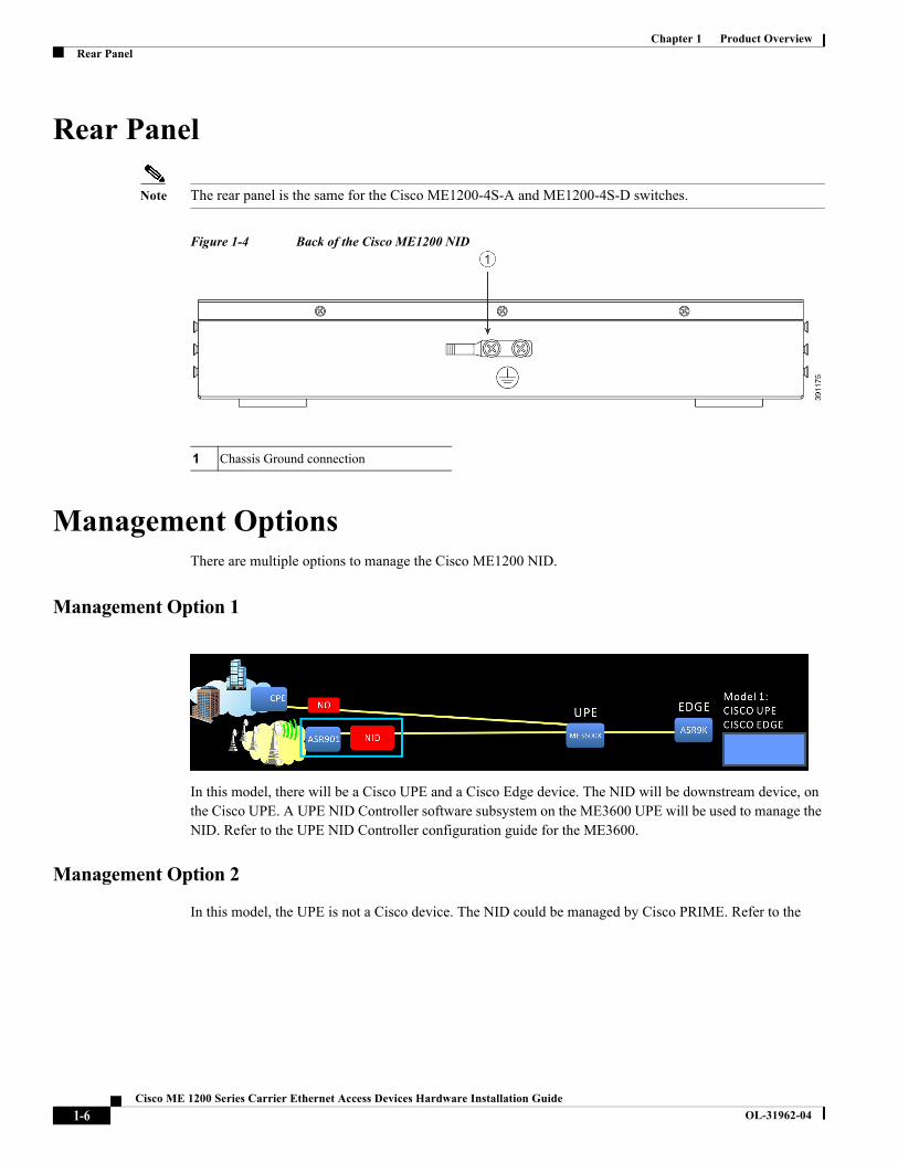
Rear Panel
Note The rear panel is the same for the Cisco ME1200-4S-A and ME1200-4S-D switches.
Figure 1-4 Back of the Cisco ME1200 NID
Management OptionsThere are multiple options to manage the Cisco ME1200 NID.
Management Option 1
In this model, there will be a Cisco UPE and a Cisco Edge device. The NID will be downstream device, on the Cisco UPE. A UPE NID Controller software subsystem on the ME3600 UPE will be used to manage the NID. Refer to the UPE NID Controller configuration guide for the ME3600.
Management Option 2
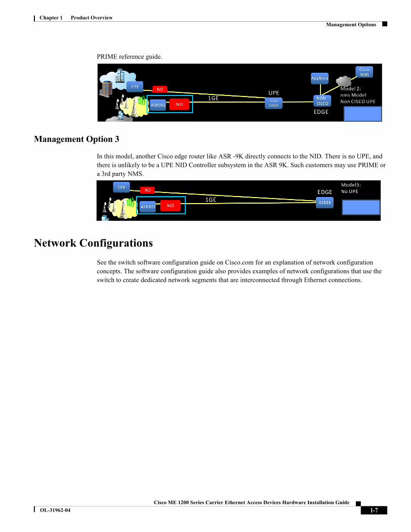
In this model, the UPE is not a Cisco device. The NID could be managed by Cisco PRIME. Refer to the
1 Chassis Ground connection
1-6Cisco ME 1200 Series Carrier Ethernet Access Devices Hardware Installation Guide
OL-31962-04
Chapter 1 Product OverviewManagement Options
PRIME reference guide.
Management Option 3
In this model, another Cisco edge router like ASR -9K directly connects to the NID. There is no UPE, and there is unlikely to be a UPE NID Controller subsystem in the ASR 9K. Such customers may use PRIME or a 3rd party NMS.
Network Configurations
See the switch software configuration guide on Cisco.com for an explanation of network configuration concepts. The software configuration guide also provides examples of network configurations that use the switch to create dedicated network segments that are interconnected through Ethernet connections.
1-7Cisco ME 1200 Series Carrier Ethernet Access Devices Hardware Installation Guide
OL-31962-04

Chapter 1 Product OverviewManagement Options
1-8Cisco ME 1200 Series Carrier Ethernet Access Devices Hardware Installation Guide
OL-31962-04
Cisco ME 1200 Series Carrier Ether
OL-31962-04
C H A P T E R 2
Installing the Cisco ME 1200 NID• Warnings, page 2-1
• Installation Guidelines, page 2-3
• Installation the Switch, page 2-4
• Installing and Removing SFP Modules, page 2-9
• Connecting to the 10/100/1000 Ports, page 2-11
• Initial Configuration, page 2-12
WarningsThese warnings are translated into several languages in the Regulatory Compliance and Safety Information for the Cisco ME1200 NID Switches document that is available online.
Warning Before working on equipment that is connected to power lines, remove jewelry (including rings, necklaces, and watches). Metal objects will heat up when connected to power and ground and can cause serious burns or weld the metal object to the terminals. Statement 43
Warning Do not stack the chassis on any other equipment. If the chassis falls, it can cause severe bodily injury and equipment damage. Statement 48
Warning Ethernet cables must be shielded when used in a non-central office environment.
Note Ethernet cables must be shielded and grounded at both ends when they are used in a non-central office environment.
Warning Do not work on the system or connect or disconnect cables during periods of lightning activity. Statement 1001
2-1net Access Devices Hardware Installation Guide

Chapter 2 Installing the Cisco ME 1200 NIDWarnings
Warning Read the installation instructions before connecting the system to the power source. Statement 1004
Warning To prevent bodily injury when mounting or servicing this unit in a rack, you must take special precautions to ensure that the system remains stable. The following guidelines are provided to ensure your safety:This unit should be mounted at the bottom of the rack if it is the only unit in the rack• When mounting this unit in a partially filled rack, load the rack from the bottom to the top withthe heaviest component at the bottom of the rack. • If the rack is provided with stabilizing devices, install the stabilizers before mounting orservicing the unit in the rack. Statement 1006
Warning The plug-socket combination must be accessible at all times, because it serves as the main disconnecting device. Statement 1019
Warning This equipment must be grounded. Never defeat the ground conductor or operate the equipment in the absence of a suitably installed ground conductor. Contact the appropriate electrical inspection authority or an electrician if you are uncertain that suitable grounding is available. Statement 1024
Warning Only trained and qualified personnel should be allowed to install, replace, or service this equipment. Statement 1030
Warning Ultimate disposal of this product should be handled according to all national laws and regulations. Statement 1040
Warning For connections outside the building where the equipment is installed, the following ports must be connected through an approved network termination unit with integral circuit protection. 10/100/1000 Ethernet Statement 1044
Warning When installing or replacing the unit, the ground connection must always be made first and disconnected last. Statement 1046
Warning No user-serviceable parts inside. Do not open. Statement 1073
Warning Installation of the equipment must comply with local and national electrical codes. Statement 1074
2-2Cisco ME 1200 Series Carrier Ethernet Access Devices Hardware Installation Guide
OL-31962-04
Chapter 2 Installing the Cisco ME 1200 NIDInstallation Guidelines
Caution The intra-building port(s) of the equipment or subassembly is suitable for connection to intra-building or unexposed wiring or cabling only. The intra-building port(s) of the equipment or subassembly MUST NOT be metallically connected to interfaces which connect to the OSP or its wiring. These interfaces are designed for use as intra-building interfaces only (Type 2 or Type 4 ports as described in GR-1089-CORE, Issue 5) and require isolation from the exposed OSP cabling. The addition of Primary Protectors is not sufficient protection in order to connect these interfaces metallically to OSP wiring.
You can use the grounding lug to attach a wrist strap for ESD protection during servicing.
Warning To prevent the system from overheating, do not operate it in an area that exceeds the maximum recommended ambient temperature of: 149•F (65•C) Statement 1047
Warning This unit might have more than one power supply connection. All connections must be removed to de-energize the unit. Statement 1028
Installation Guidelines
Before installing the switch, verify that these guidelines are met:
• For Ethernet ports and 1000BASE-T SFP module ports, cable lengths from the switch to connecteddevices can be up to 328 feet (100 meters).
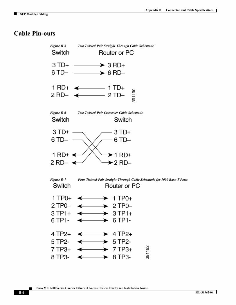
• For cable requirements for 1000BASE-T SFP module connections, see the “Cable Pin-outs” section onfigure B-7.
• Operating environment is within the ranges listed in Appendix A, "Technical Specifications"
• Front-panel indicators can be easily read, and access to ports is sufficient for unrestricted cabling
• AC power cord reaches from the power outlet to the connector.
• Cabling is away from sources of electrical noise, such as radios, power lines, and fluorescent lightingfixtures. Make sure that the cabling is safely away from other devices that might damage the cables.
• Airflow around the switch and through the vents is unrestricted.
• For an outside plant installation (cell site cabinet, hut etc.), it is required that the ME 1200 switch beprotected against airborne contaminants, dust, moisture, insects, pests, corrosive gases, polluted air orother reactive elements present in the outside air. To achieve this level of protection, we recommend thatthe unit be installed in a fully sealed enclosure or cabinet. Examples of such cabinets include IP65cabinets with heat exchanger complying with Telecordia GR487. Temperature must be maintainedwithin –40ºC to 65ºC.
Note If the switch is installed in a closed or multi-rack assembly, the temperature around it might be greater than normal room temperature.
• Before you connect the switch to a power source, note the power consumption specifications inAppendix A, "Technical Specifications"
2-3Cisco ME 1200 Series Carrier Ethernet Access Devices Hardware Installation Guide
OL-31962-04

Chapter 2 Installing the Cisco ME 1200 NIDInstallation the Switch
Verifying Switch Operation
Before installing the switch in a rack, on a wall, or on a table or shelf, you should power the switch and verify that the switch passes POST.
• To power on the AC switch, connect one end of the AC power cord to the AC power connector on theswitch, and connect the other end of the power cord to an AC power outlet.
• To power on a DC switch, see Chapter 3, "Wiring the DC Input Power Source"
When the switch powers on, it automatically begins the POST, a series of tests that verifies that the switch functions properly. When the switch begins POST. When POST completes successfully, the system LED solid green.
Installing the Switch
• Rack-Mounting, page 2-4
• Mounting the Switch on a Wall, page 2-7
• Desktop Mounting, page 2-8
Rack-Mounting
To install the switch in a 19-inch, 23-inch, or a European Telecommunications Standards Institute (ETSI) rack, follow these instructions.
Attaching Brackets to the Switch
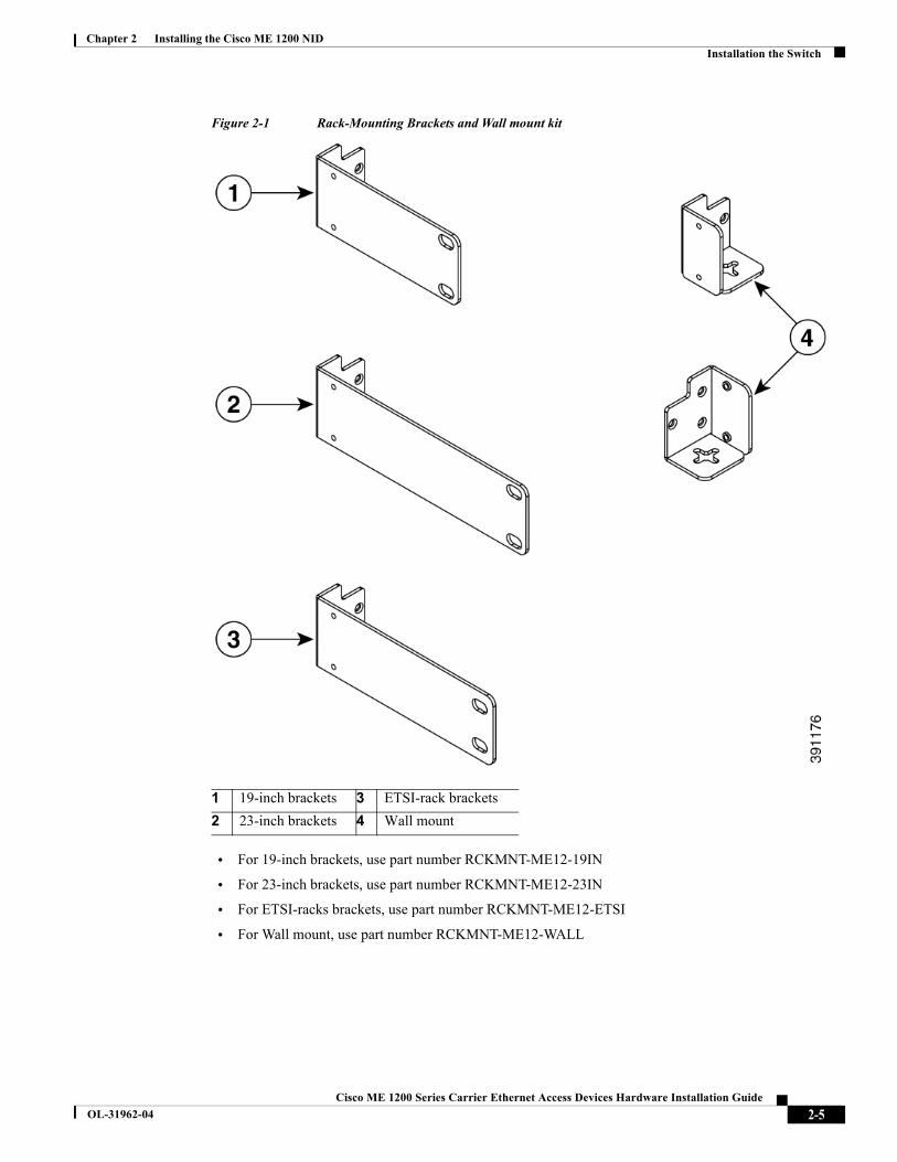
The bracket orientation and the brackets that you use depend on whether you are attaching the brackets for a19-inch, 23-inch, ETSI rack, or Wall mount. Figure 2-1 shows the types of mounting brackets.
2-4Cisco ME 1200 Series Carrier Ethernet Access Devices Hardware Installation Guide
OL-31962-04
Chapter 2 Installing the Cisco ME 1200 NIDInstallation the Switch
Figure 2-1 Rack-Mounting Brackets and Wall mount kit
• For 19-inch brackets, use part number RCKMNT-ME12-19IN
• For 23-inch brackets, use part number RCKMNT-ME12-23IN
• For ETSI-racks brackets, use part number RCKMNT-ME12-ETSI
• For Wall mount, use part number RCKMNT-ME12-WALL
1 19-inch brackets 3 ETSI-rack brackets
2 23-inch brackets 4 Wall mount
2-5Cisco ME 1200 Series Carrier Ethernet Access Devices Hardware Installation Guide
OL-31962-04
Chapter 2 Installing the Cisco ME 1200 NIDInstallation the Switch
Attaching Brackets to the Switch
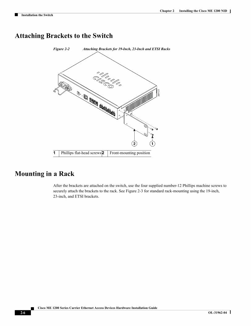
Figure 2-2 Attaching Brackets for 19-Inch, 23-Inch and ETSI Racks
Mounting in a Rack
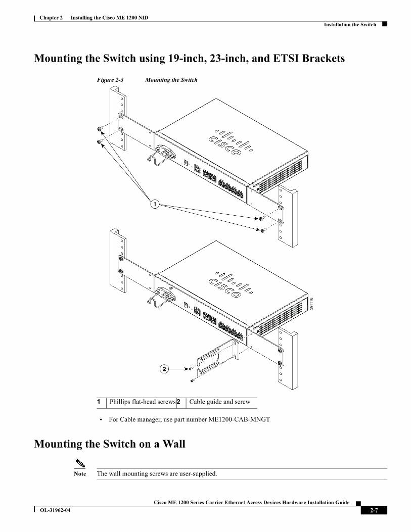
After the brackets are attached on the switch, use the four supplied number-12 Phillips machine screws to securely attach the brackets to the rack. See Figure 2-3 for standard rack-mounting using the 19-inch, 23-inch, and ETSI brackets.
1 Phillips flat-head screws2 Front-mounting position
2-6Cisco ME 1200 Series Carrier Ethernet Access Devices Hardware Installation Guide
OL-31962-04
Chapter 2 Installing the Cisco ME 1200 NIDInstallation the Switch
Mounting the Switch using 19-inch, 23-inch, and ETSI Brackets
Figure 2-3 Mounting the Switch
• For Cable manager, use part number ME1200-CAB-MNGT
Mounting the Switch on a Wall
Note The wall mounting screws are user-supplied.
1 Phillips flat-head screws2 Cable guide and screw
2-7Cisco ME 1200 Series Carrier Ethernet Access Devices Hardware Installation Guide
OL-31962-04

Chapter 2 Installing the Cisco ME 1200 NIDInstallation the Switch
For the best support of the switch and cables, make sure that the switch is attached securely to wall studs or to a firmly attached plywood mounting backboard.
Warning Read the wall-mounting instructions carefully before beginning installation. Failure to use the correct hardware or to follow the correct procedures could result in a hazardous situation to people and damage to the system. Statement 378
Figure 2-4 Mounting Cisco ME1200 NID on a Wall
You need to do these tasks to complete the installation:
• Power on the switch. See the “Verifying Switch Operation” section on page 2-4
• Connect to the console port, and run the initial configuration. See the Cisco NID Controller Guide forinstructions.
• Connect to the front-panel ports. See the “Connecting to the 10/100/1000 Ports” and the“Connecting toFiber-Optic SFP Modules”.
Desktop Mounting
Follow these steps to install the switch on a table or a shelf:
1 User-supplied screws
2-8Cisco ME 1200 Series Carrier Ethernet Access Devices Hardware Installation Guide
OL-31962-04

Chapter 2 Installing the Cisco ME 1200 NIDInstalling and Removing SFP Modules
Step 1 The rubber feet are included in the accessory kit. Attach the four adhesive rubber feet to the bottom of the switch
Figure 2-5 Attaching the adhesive rubber feet
Figure 2-6 On Table Reference
Step 2 Set the device on a flat surface near a power source, making sure there are at least two inches of space on all sides for proper air flow.
Installing and Removing SFP Modules
Installing SFP Modules
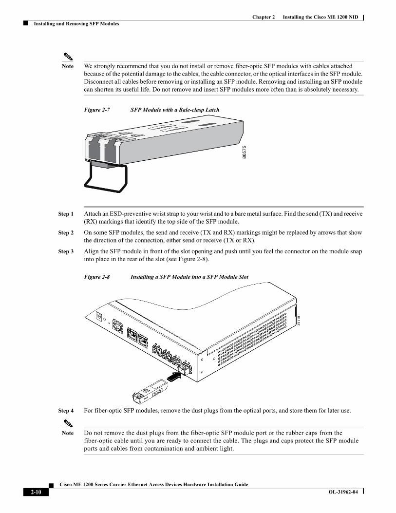
Figure 2-7 shows a SFP module that has a bale-clasp latch.
1 Rubber feet
2-9Cisco ME 1200 Series Carrier Ethernet Access Devices Hardware Installation Guide
OL-31962-04
Chapter 2 Installing the Cisco ME 1200 NIDInstalling and Removing SFP Modules
Note We strongly recommend that you do not install or remove fiber-optic SFP modules with cables attached because of the potential damage to the cables, the cable connector, or the optical interfaces in the SFP module. Disconnect all cables before removing or installing an SFP module. Removing and installing an SFP module can shorten its useful life. Do not remove and insert SFP modules more often than is absolutely necessary.
Figure 2-7 SFP Module with a Bale-clasp Latch
Step 1 Attach an ESD-preventive wrist strap to your wrist and to a bare metal surface. Find the send (TX) and receive (RX) markings that identify the top side of the SFP module.
Step 2 On some SFP modules, the send and receive (TX and RX) markings might be replaced by arrows that show the direction of the connection, either send or receive (TX or RX).
Step 3 Align the SFP module in front of the slot opening and push until you feel the connector on the module snap into place in the rear of the slot (see Figure 2-8).
Figure 2-8 Installing a SFP Module into a SFP Module Slot
Step 4 For fiber-optic SFP modules, remove the dust plugs from the optical ports, and store them for later use.
Note Do not remove the dust plugs from the fiber-optic SFP module port or the rubber caps from the fiber-optic cable until you are ready to connect the cable. The plugs and caps protect the SFP module ports and cables from contamination and ambient light.
2-10Cisco ME 1200 Series Carrier Ethernet Access Devices Hardware Installation Guide
OL-31962-04

Chapter 2 Installing the Cisco ME 1200 NIDConnecting to the 10/100/1000 Ports
Step 5 Insert the LC cable connector into the SFP module.
Removing SFP Modules
Step 1 Attach an ESD-preventive wrist strap to your wrist and to a bare metal surface.
Step 2 Disconnect the cable from the SFP module. For reattachment, note which cable connector plug is send (TX) and which is receive (RX).
Step 3 Insert a dust plug into the optical ports of the SFP module to keep the optical interfaces clean.
Step 4 Pull the bale out and down to eject the module.
Figure 2-9
Step 5 Grasp the SFP module, and carefully remove it from the module slot.
Step 6 For fiber-optic SFP modules, insert a dust plug into the optical ports of the SFP module to keep the optical interfaces clean.
Step 7 Place the removed SFP module in an antistatic bag or other protective environment.
Connecting to the 10/100/1000 PortsThe switch 10/100/1000 ports configure themselves to operate at the speed of attached devices. If the attached ports do not support auto-negotiation, you can explicitly set the speed and duplex parameters. Connecting devices that do not auto-negotiate or that have their speed and duplex parameters manually set can reduce performance or result in no linkage.To maximize performance, choose one of these methods for configuring the Ethernet ports:
• Let the ports auto-negotiate both speed and duplex.
• Set the port speed and duplex parameters on both ends of the connection.
Follow these steps to connect to 10BASE-T, 100BASE-TX, or 1000-BASE-T devices:
2-11Cisco ME 1200 Series Carrier Ethernet Access Devices Hardware Installation Guide
OL-31962-04
Chapter 2 Installing the Cisco ME 1200 NIDInitial Configuration
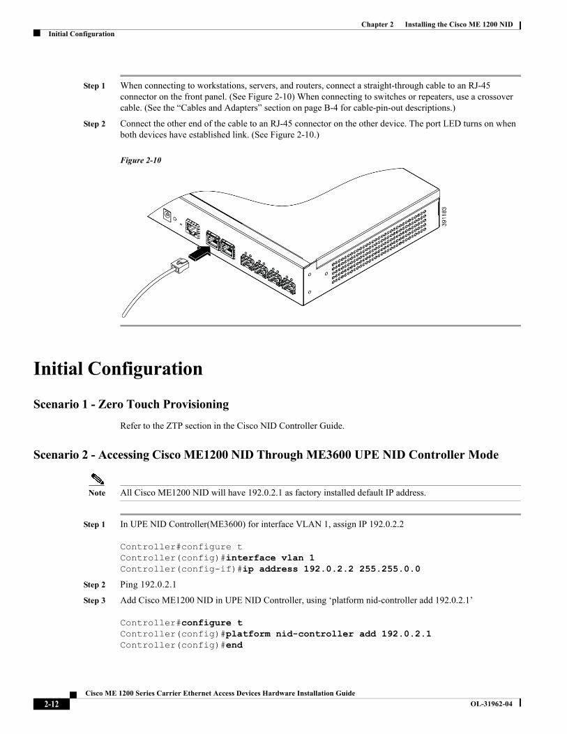
Step 1 When connecting to workstations, servers, and routers, connect a straight-through cable to an RJ-45 connector on the front panel. (See Figure 2-10) When connecting to switches or repeaters, use a crossover cable. (See the “Cables and Adapters” section on page B-4 for cable-pin-out descriptions.)
Step 2 Connect the other end of the cable to an RJ-45 connector on the other device. The port LED turns on when both devices have established link. (See Figure 2-10.)
Figure 2-10
Initial Configuration
Scenario 1 - Zero Touch Provisioning
Refer to the ZTP section in the Cisco NID Controller Guide.
Scenario 2 - Accessing Cisco ME1200 NID Through ME3600 UPE NID Controller Mode
Note All Cisco ME1200 NID will have 192.0.2.1 as factory installed default IP address.
Step 1 In UPE NID Controller(ME3600) for interface VLAN 1, assign IP 192.0.2.2
Controller#configure tController(config)#interface vlan 1Controller(config-if)#ip address 192.0.2.2 255.255.0.0
Step 2 Ping 192.0.2.1
Step 3 Add Cisco ME1200 NID in UPE NID Controller, using ‘platform nid-controller add 192.0.2.1’
Controller#configure tController(config)#platform nid-controller add 192.0.2.1Controller(config)#end
2-12Cisco ME 1200 Series Carrier Ethernet Access Devices Hardware Installation Guide
OL-31962-04
Chapter 2 Installing the Cisco ME 1200 NIDInitial Configuration
Step 4 Check if the Cisco ME1200 NID has been added to UPE NID Controller,
Controller#show platform nid-controller nids NID_ID MAC Address IP Address Lease Physical Port VLAN TFTP Server Type1 n/a 192.0.2.1 n/a n/a n/a n/a static
Note Step 1 to Step 4 are performed so that for the first time, we can access Cisco ME1200 NID through the UPE NID Controller ME3600 with the default factory IP address Cisco ME1200 NID comes with (192.0.2.1). The above steps 1 to 4 are mandatory and sufficient to establish the initial connectivity between the UPE NID Controller and Cisco ME1200 NID.
Below steps are performed in order to configure port as trunk and establish the connectivity on a different SVI. This also gives the provision to configure default IP route for reachability to various servers.
Note Prerequisite :1. UPE NID Controller should be configured with a different VLAN other than VLAN 1.2. Below configs are assuming UPE NID Controller interface 0/1 is connected to Cisco ME1200 NID1/1, change the interface configs as applicable.
Step 5 Controller#configure tController(config)#interface vlan 2Controller(config-if)#ip address 7.6.15.60 255.255.0.0
Step 6 The interface on UPE NID Controller which is connected to Cisco ME1200 NID needs to be configured trunk with the specified vlan allowed.
Controller#conf tEnter configuration commands, one per line. End with CNTL/Z.Controller(config)#interface gigabitEthernet 0/1Controller(config-if)#switchport mode trunkController(config-if)#switchport trunk allowed vlan 2
Step 7 Now, from the UPE NID Controller configure the desired management vlan on Cisco ME1200 NID using ‘provisionportvlantype’ template and assign svi for the desired vlan interface.
Controller#conf tController(config)#controller nid 1/1Controller(config-controller)#provisionportVlanPortType Controller(config-controller-ProvisionPortVlanPortType)#createintVlan createIntVlanReq vlan_id 2Controller(config-controller-ProvisionPortVlanPortType)#createintVlan createIntVlanReq address ipv4 ipv4_address address 7.6.15.59Controller(config-controller-ProvisionPortVlanPortType)#createintVlan createIntVlanReq address ipv4 ipv4_address mask 255.255.0.0Controller(config-controller-ProvisionPortVlanPortType)#createintVlan commit
Step 8 Now add route using ‘nidmanagemet’ template.
Controller#conf tController(config)#controller nid 1/1
2-13Cisco ME 1200 Series Carrier Ethernet Access Devices Hardware Installation Guide
OL-31962-04
Chapter 2 Installing the Cisco ME 1200 NIDInitial Configuration
Controller(config-controller)#ProvisionNIDMgmtTypeController(config-controller-ProvisionNIDMgmtType)#setiproute setIpRouteReq ??ipv4_address 0.0.0.0Controller(config-controller-ProvisionNIDMgmtType)#setiproute setIpRouteReq ipv4_mask 0.0.0.0Controller(config-controller-ProvisionNIDMgmtType)#setiproute setIpRouteReq gateway_ip 7.6.0.1Controller(config-controller-ProvisionNIDMgmtType)#setiproute commit
Step 9 Configure the connected Cisco ME1200 NID interface as trunk and allow the specified VLAN.
Controller#conf tController(config)#controller nid 1/1Controller(config-controller)#ProvisionPortVlanPortTypeController(config-controller-ProvisionPortVlanPortType)# modifySwPort modifySWPortConfig interface 1Controller(config-controller-ProvisionPortVlanPortType)#modifySwPort modifySWPortConfig mode trunk allowed vlan 2Controller(config-controller-ProvisionPortVlanPortType)#modifySwPort commit
Step 10 After above steps, using ‘platform nid-controller’ add the NID with the desired IP.
Controller#conf tController(config)#platform nid-controller add 7.6.15.59Controller(config)#end
Step 11 Check if the Cisco ME1200 NID has been added to UPE NID Controller,
Controller#show platform nid-controller nids NID_ID MAC Address IP Address Lease Physical Port VLAN TFTP Server Type1 n/a 192.0.2.1 n/a n/a n/a n/a static2 n/a 7.6.15.59 n/a n/a n/a n/a static
Step 12 Now, using ‘controller nid 1/2’ the Cisco ME1200 NID can be accessed on a different SVI.
2-14Cisco ME 1200 Series Carrier Ethernet Access Devices Hardware Installation Guide
OL-31962-04

Cisco ME 1200 Series Carrier Ether
OL-31962-04
C H A P T E R 3
AC and DC Input PowerThis chapter provides the installation instructions for the AC and DC input power for the Cisco ME1200
NID switches
• Installing an AC Power Cord Retainer Clip, page 3-1
• Installing an AC Power Cord, page 3-2
• Installing an AC-to-DC Power Adapter, page 3-2
• Wiring the DC Input Power Source, page 3-3
• Grounding the Switch, page 3-4
Installing an AC Power Cord Retainer Clip
Follow these steps to install a AC power cord retainer clip on the switch.
Step 1 Press the both side of the retainer clip and installing retainer clip through the hole on the hex screws.(see figure 3-1)
3-1net Access Devices Hardware Installation Guide

Chapter 3 AC and DC Input PowerInstalling an AC Power Cord
Figure 3-1 AC Power Retainer
Installing an AC Power CordThe AC input needs a power cord with IEC-C-15 type connector.
Attach the power-cord retainer clip to the switch. (see Figure 3-2).
Figure 3-2 AC Power Cord and Retainer in a Switch
Installing an AC-to-DC Power AdapterThe DC jack’s central post is 2.5mm wide and conforms to the DC receptacle (2.5mm).
Step 1 Connect the DC jack cable between ME1200-4S-A/D and adapter
3-2Cisco ME 1200 Series Carrier Ethernet Access Devices Hardware Installation Guide
OL-31962-04
Chapter 3 AC and DC Input PowerWiring the DC Input Power Source
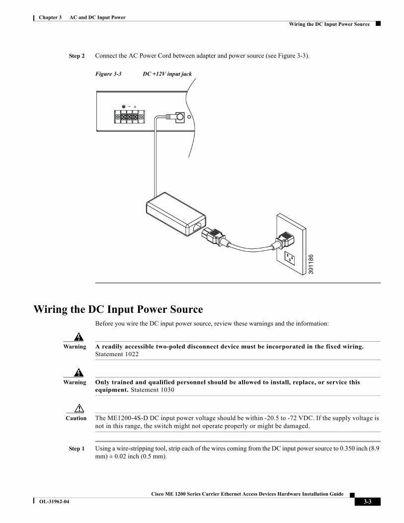
Step 2 Connect the AC Power Cord between adapter and power source (see Figure 3-3).
Figure 3-3 DC +12V input jack
Wiring the DC Input Power SourceBefore you wire the DC input power source, review these warnings and the information:
Warning A readily accessible two-poled disconnect device must be incorporated in the fixed wiring. Statement 1022
Warning Only trained and qualified personnel should be allowed to install, replace, or service this equipment. Statement 1030
Caution The ME1200-4S-D DC input power voltage should be within -20.5 to -72 VDC. If the supply voltage is not in this range, the switch might not operate properly or might be damaged.
Step 1 Using a wire-stripping tool, strip each of the wires coming from the DC input power source to 0.350 inch (8.9 mm) ± 0.02 inch (0.5 mm).
3-3Cisco ME 1200 Series Carrier Ethernet Access Devices Hardware Installation Guide
OL-31962-04

Chapter 3 AC and DC Input PowerGrounding the Switch
Figure 3-4 Stripping the DC Input Power Source Wire
Step 2 Crimp the fork-type terminals to the 14 or 16 AWG DC power input wires.
Step 3 Connect the wires to the DC input power terminals as shown in Figure 3-4 Make sure to match the polarity (negative to negative, positive to positive) when connecting the wires to the terminal.)
Figure 3-5 Connecting the DC Input Power Terminal Blocks
Step 4 Use a ratcheting torque Phillips-head screwdriver to torque the terminal-block screw to 14 in-lb.
Caution Do not over-torque the terminal-block screws. The recommended maximum torque is 14 in-lb.
Grounding the SwitchFollow the grounding procedure instructions and observe these warnings.
3-4Cisco ME 1200 Series Carrier Ethernet Access Devices Hardware Installation Guide
OL-31962-04

Chapter 3 AC and DC Input PowerGrounding the Switch
Warning This equipment must be grounded. Never defeat the ground conductor or operate the equipment in the absence of a suitably installed ground conductor. Contact the appropriate electrical inspection authority or an electrician if you are uncertain that suitable grounding is available. Statement 1024
Warning When installing or replacing the unit, the ground connection must always be made first and disconnected last. Statement 1046
Caution To make sure that the equipment is reliably connected to earth ground, follow the grounding procedure instructions, and use a UL-listed lug suitable for number-6 AWG wire and two number-10-32 ground-lug screws.
Follow these steps to install a dual-hole ground lug on the switch. Make sure to follow any groundingrequirements at your site.
Step 1 Locate the dual-hole lug that ships with the switch. (The grounding lug is included in the packaging accessories.)
Step 2 If your ground wire is insulated, use a wire stripping tool to strip the 6 AWG ground wire to 0.875 inch (12.7 mm) ± 0.02 inch (0.5 mm)
Figure 3-6 Stripping the Ground Wire
Step 3 Slide the open end of the ground lug over the exposed area of the wire.
Step 4 Crimp the ground lug to the wire (see Figure 3-7).
3-5Cisco ME 1200 Series Carrier Ethernet Access Devices Hardware Installation Guide
OL-31962-04

Chapter 3 AC and DC Input PowerGrounding the Switch
Figure 3-7 Crimping the Ground Lug
Step 5 Attach the dual-hole lug and the wire assembly to the chassis ground connection with the supplied screws (see Figure 3-8).
Figure 3-8 Attaching the Ground Lug and Wire Assembly
Step 6 Use a ratcheting torque Phillips-head screwdriver to torque the ground-lug screws to 32 in-lb.
Step 7 Connect the other end of the grounding wire to an appropriate grounding point at your site or to the rack.
3-6Cisco ME 1200 Series Carrier Ethernet Access Devices Hardware Installation Guide
OL-31962-04

Cisco ME 1200 Series Carrier Ether
OL-31962-04
C H A P T E R 4
Troubleshooting• Diagnosing Problems, page 4-1
• Switch Performance, page 4-1
• Finding the Switch Serial Number, page 4-2
Diagnosing Problems
The LEDs on the front panel provide troubleshooting information about the switch. They show power-on self-test (POST) failures, port-connectivity problems, and overall switch performance. You can also get statistics from the CLI on the UPE NID Controller. See the Cisco NID Controller guide on Cisco.com for more information.
Switch Performance
Speed, Duplex, and Auto-negotiation
If the port statistics show a large amount of alignment errors, frame check sequence (FCS), or late-collisionserrors, this might mean a speed or duplex mismatch.
A common issue with speed and duplex is when the duplex settings are mismatched between two switches, between a switch and a router, or between the switch and a workstation or server. Mismatches can happen when manually setting the speed and duplex or from auto-negotiation issues between the two devices.To maximize switch performance and to ensure a link, follow one of these guidelines when changing the duplex or speed settings.
• Let both ports auto-negotiate both speed and duplex.
• Manually set the speed and duplex parameters for the ports on both ends of the connection.
• If a remote device does not auto-negotiate, set the same duplex settings on the two ports. The speedparameter adjusts itself even if the connected port does not auto-negotiate.
4-1net Access Devices Hardware Installation Guide
Chapter 4 TroubleshootingFinding the Switch Serial Number
Auto-negotiation and NICs
Problems sometimes occur between the switch and third-party network interface cards (NICs). By default, the switch ports and interfaces are set to auto-negotiate. Devices like laptops or other devices are commonly set to auto-negotiate, yet sometimes auto-negotiation issues occur.
To troubleshoot auto-negotiation problems, try manually setting both sides of the connection. If this does notsolve the problem, there could be a problem with the firmware or software on your NIC. You can resolve this by upgrading the NIC driver to the latest available version.
Cabling Distance
If the port statistics show excessive FCS, late-collision, or alignment errors, verify that the cable distance from the switch to the connected device meets the recommended guidelines. See the “Connector and Cable Specifications” for cabling guidelines.
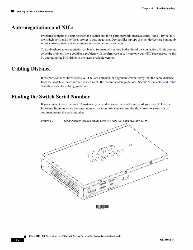
Finding the Switch Serial NumberIf you contact Cisco Technical Assistance, you need to know the serial number of your switch. Use the following figure to locate the serial number location. You can also use the show inventory user EXEC command to get the serial number.
Figure 4-1 Serial Number location on the Cisco ME1200-4S-A and ME1200-4S-D
4-2Cisco ME 1200 Series Carrier Ethernet Access Devices Hardware Installation Guide
OL-31962-04

Cisco ME 1200 Series Carrier Ethernet Ac
OL-31962-04
A
P P E N D I X A Technical Specifications• Environmental and Technical Specifications for the Switch, page A-1
• Environmental and Technical Specifications for the Power Adapter, page A-2
Environmental and Technical Specifications for the Switch
Table A-1 Environmental Ranges for the Switch
Environmental Ranges
Relative humidity 5 to 95% (non condensing)
Operating temperature -40° to 149°F(-40° to 65°C)
Storage temperature -49° to 185°F(-45° to 85°C)
Operating altitude Up to 4,000m (without external adapter)Up to 2,000m (with external adapter)
Storage altitude Up to 15,000 ft (4570 m)
Table A-2 Technical Specifications ME1200-4S-A
Physical Dimensions
weight 2.84 lb (1.29 kg)
Dimensions( H x W x D) 1.73 x 10.59 x 7.09 in. (4.4 x 26.9 x 18.0 cm)
AC Power Requirements
Power consumption with 1 AC internal power supply installed
Total:30.30 BTUs per hour (maximum).Maximum: 8.88 W (worst-case SFPs, 100% traffic).Typical: 8.74 W (4 SFPs with 1000BASE-SX, 100% traffic).Minimum: 5.71 W (no cables or SFP modules installed).Power rating: 120 V (0.018 KVA), 230 V (0.023KVA).
Power consumption with 1 AC-to-DC 12VDC external power adapter installed
Total: 30.61 BTUs per hour (maximum).Maximum:8.97 W (worst-case SFPs, 100% traffic).Typical:8.58 W (4 SFPs with 1000BASE-SX, 100% traffic).Minimum: 5.54 W (no cables or SFP modules installed).Power rating: 120 V (0.018 KVA), 230 V (0.023 KVA).
A-1cess Devices Hardware Installation Guide
Appendix A Technical SpecificationsEnvironmental and Technical Specifications for the Power Adapter
Environmental and Technical Specifications for the Power Adapter
Table A-3 Technical Specifications ME1200-4S-D
Physical Dimensions
weight 3.13 lb (1.42 kg)
Dimensions( H x W x D) 1.73 x 10.59 x 7.09 in. (4.4 x 26.9 x 18.0 cm)
DC Power Requirements
Input voltage -20.5 to -72 VDC.
Power consumption with 1 DC internal power supply installed
Total: 30.78 BTUs per hour (maximum).Maximum: 9.02 W (-20.5VDC input, worst-case SFPs, 100% traffic).Typical-1: 8.4 W (24 VDC, 4 SFPs with 1000BASE-SX, 100% traffic).Typical-2: 8.64 W (48 VDC, 4 SFPs with 1000BASE-SX, 100% traffic).Minimum: 5.76 W (72 VDC, no cables or SFP modules installed).
Power consumption with 1 AC-to-DC 12VDC external power adapter installed
Total: 28.53 BTUs per hour (maximum).Maximum: 8.36 W (worst-case SFPs, 100% traffic).Typical:8.00 W (4 SFPs with 1000BASE-SX, 100% traffic).Minimum:5.54 W (no cables or SFP modules installed).Power rating: 120 V (0.0168 KVA), 230 V (0.0207 KVA).
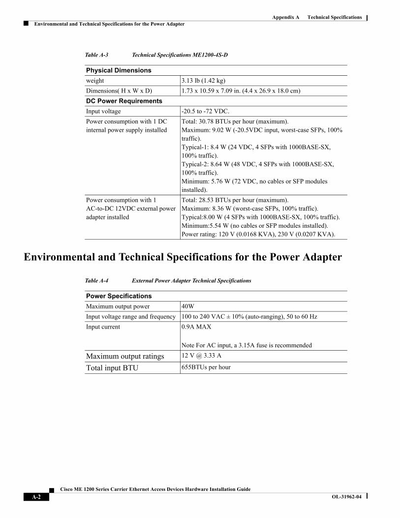
Table A-4 External Power Adapter Technical Specifications
Power Specifications
Maximum output power 40W
Input voltage range and frequency 100 to 240 VAC ± 10% (auto-ranging), 50 to 60 Hz
Input current 0.9A MAX
Note For AC input, a 3.15A fuse is recommended
Maximum output ratings 12 V @ 3.33 A
Total input BTU 655BTUs per hour
A-2Cisco ME 1200 Series Carrier Ethernet Access Devices Hardware Installation Guide
OL-31962-04
Cisco ME 1200 Series Carrier Ethernet Ac
OL-31962-04
A
P P E N D I X B Connector and Cable Specifications• 10/100/1000, page B-1
• SFP Module Connectors, page B-1
• SFP Module Cabling, page B-2
• Console Port Adapter Pin-outs, page B-5
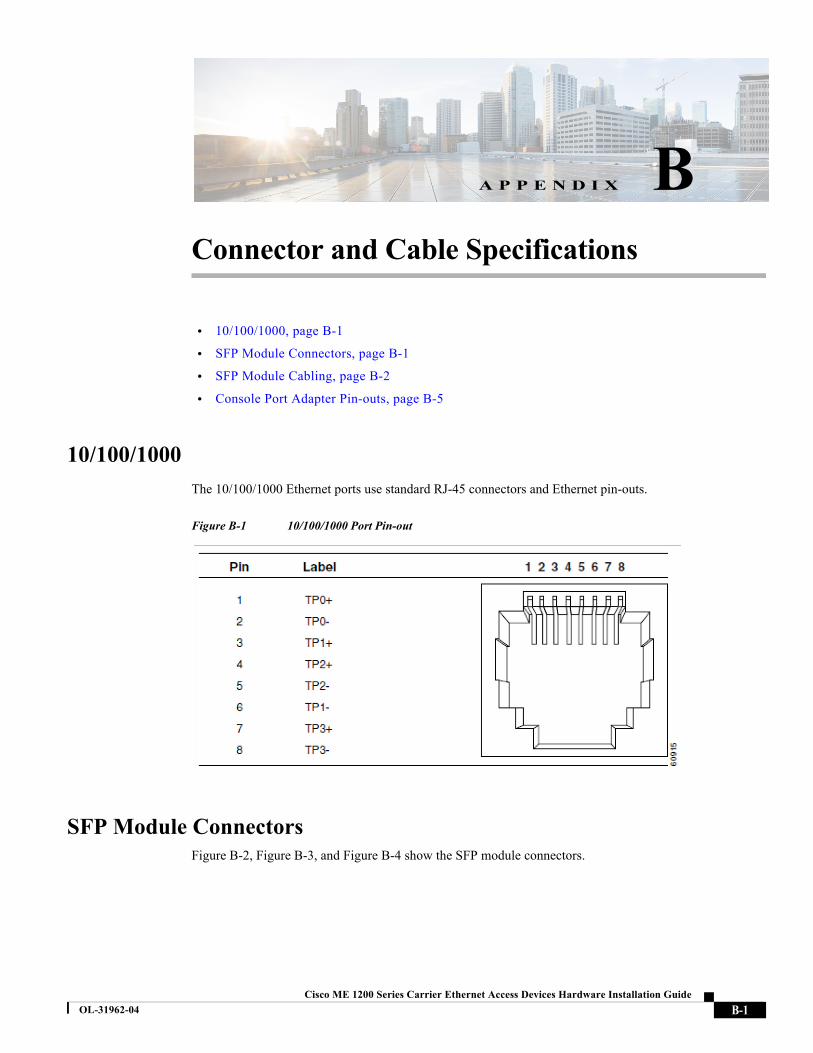
10/100/1000
The 10/100/1000 Ethernet ports use standard RJ-45 connectors and Ethernet pin-outs.
Figure B-1 10/100/1000 Port Pin-out
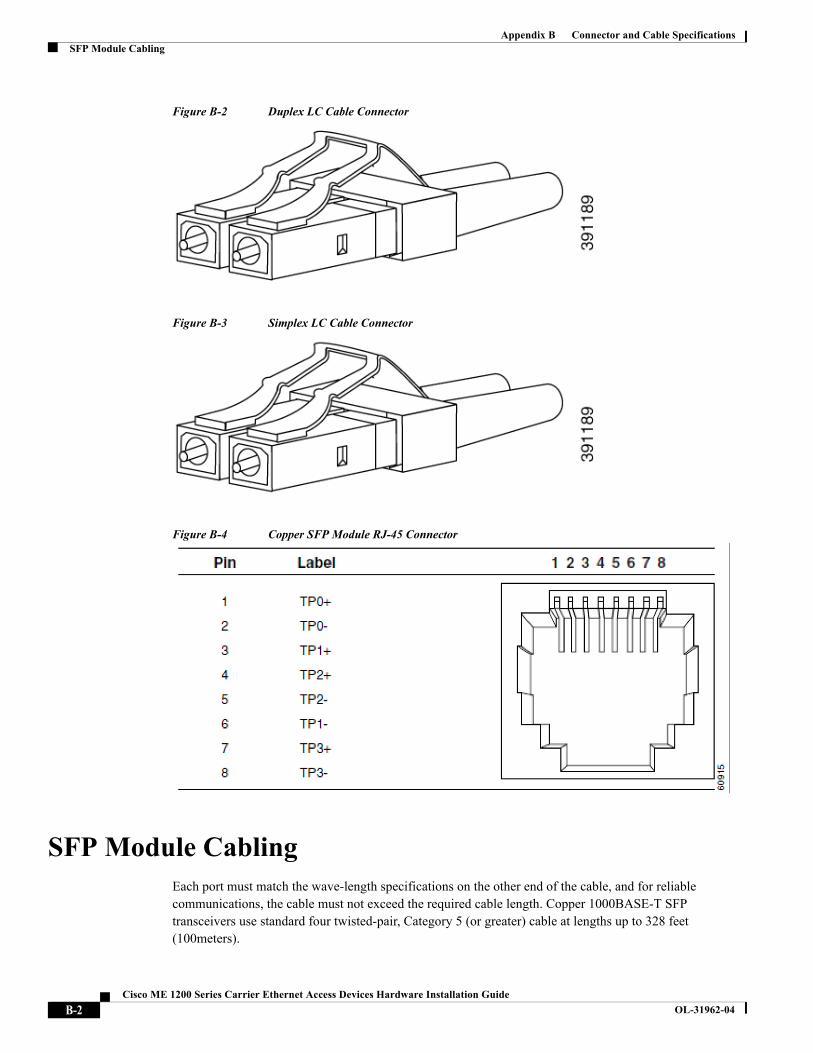
SFP Module ConnectorsFigure B-2, Figure B-3, and Figure B-4 show the SFP module connectors.
B-1cess Devices Hardware Installation Guide
Appendix B Connector and Cable SpecificationsSFP Module Cabling
Figure B-2 Duplex LC Cable Connector
Figure B-3 Simplex LC Cable Connector
Figure B-4 Copper SFP Module RJ-45 Connector
SFP Module CablingEach port must match the wave-length specifications on the other end of the cable, and for reliable communications, the cable must not exceed the required cable length. Copper 1000BASE-T SFP transceivers use standard four twisted-pair, Category 5 (or greater) cable at lengths up to 328 feet (100meters).
B-2Cisco ME 1200 Series Carrier Ethernet Access Devices Hardware Installation Guide
OL-31962-04
Appendix B Connector and Cable SpecificationsSFP Module Cabling
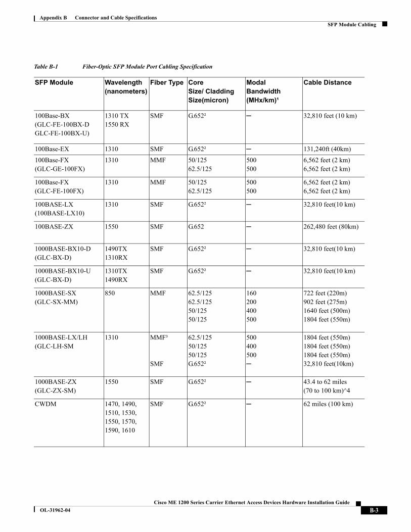
Table B-1 Fiber-Optic SFP Module Port Cabling Specification
SFP Module Wavelength(nanometers)
Fiber Type CoreSize/ Cladding Size(micron)
Modal Bandwidth (MHx/km)¹
Cable Distance
100Base-BX (GLC-FE-100BX-DGLC-FE-100BX-U)
1310 TX1550 RX
SMF G.652² ─ 32,810 feet (10 km)
100Base-EX 1310 SMF G.652² ─ 131,240ft (40km)
100Base-FX(GLC-GE-100FX)
1310 MMF 50/12562.5/125
500500
6,562 feet (2 km)6,562 feet (2 km)
100Base-FX(GLC-FE-100FX)
1310 MMF 50/12562.5/125
500500
6,562 feet (2 km)6,562 feet (2 km)
100BASE-LX(100BASE-LX10)
1310 SMF G.652² ─ 32,810 feet(10 km)
100BASE-ZX 1550 SMF G.652 ─ 262,480 feet (80km)
1000BASE-BX10-D(GLC-BX-D)
1490TX1310RX
SMF G.652² ─ 32,810 feet(10 km)
1000BASE-BX10-U(GLC-BX-D)
1310TX1490RX
SMF G.652² ─ 32,810 feet(10 km)
1000BASE-SX(GLC-SX-MM)
850 MMF 62.5/12562.5/12550/12550/125
160200400500
722 feet (220m)902 feet (275m)1640 feet (500m)1804 feet (550m)
1000BASE-LX/LH(GLC-LH-SM
1310 MMF³
SMF
62.5/12550/12550/125G.652²
500400500─
1804 feet (550m)1804 feet (550m)1804 feet (550m)32,810 feet(10km)
1000BASE-ZX(GLC-ZX-SM)
1550 SMF G.652² ─ 43.4 to 62 miles(70 to 100 km)^4
CWDM 1470, 1490, 1510, 1530, 1550, 1570, 1590, 1610
SMF G.652² ─ 62 miles (100 km)
B-3Cisco ME 1200 Series Carrier Ethernet Access Devices Hardware Installation Guide
OL-31962-04
Appendix B Connector and Cable SpecificationsSFP Module Cabling
Cable Pin-outs
Figure B-5 Two Twisted-Pair Straight-Through Cable Schematic
Figure B-6 Two Twisted-Pair Crossover Cable Schematic
Figure B-7 Four Twisted-Pair Straight-Through Cable Schematic for 1000 Base-T Ports
B-4Cisco ME 1200 Series Carrier Ethernet Access Devices Hardware Installation Guide
OL-31962-04
Appendix B Connector and Cable SpecificationsConsole Port Adapter Pin-outs
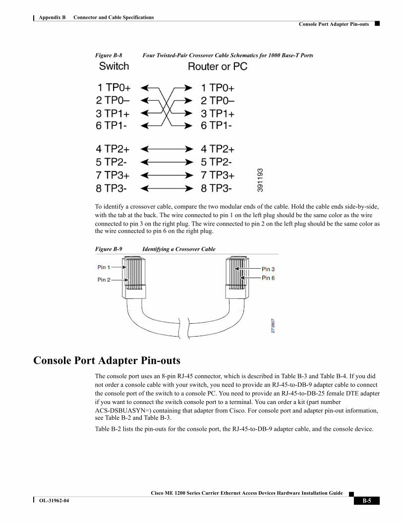
Figure B-8 Four Twisted-Pair Crossover Cable Schematics for 1000 Base-T Ports
To identify a crossover cable, compare the two modular ends of the cable. Hold the cable ends side-by-side,with the tab at the back. The wire connected to pin 1 on the left plug should be the same color as the wire connected to pin 3 on the right plug. The wire connected to pin 2 on the left plug should be the same color asthe wire connected to pin 6 on the right plug.
Figure B-9 Identifying a Crossover Cable
Console Port Adapter Pin-outsThe console port uses an 8-pin RJ-45 connector, which is described in Table B-3 and Table B-4. If you did not order a console cable with your switch, you need to provide an RJ-45-to-DB-9 adapter cable to connect the console port of the switch to a console PC. You need to provide an RJ-45-to-DB-25 female DTE adapterif you want to connect the switch console port to a terminal. You can order a kit (part number ACS-DSBUASYN=) containing that adapter from Cisco. For console port and adapter pin-out information, see Table B-2 and Table B-3.
Table B-2 lists the pin-outs for the console port, the RJ-45-to-DB-9 adapter cable, and the console device.
B-5Cisco ME 1200 Series Carrier Ethernet Access Devices Hardware Installation Guide
OL-31962-04

Appendix B Connector and Cable SpecificationsConsole Port Adapter Pin-outs
Table B-3 lists the pin-outs for the console port, RJ-45-to-DB-25 female DTE adapter, and the console device.
Note The RJ-45-to-DB-25 female DTE adapter is not supplied with the switch. You can order a kit (part number ACS-DSBUASYN=) containing this adapter from Cisco.
Table B-2 Console Port Signaling Using a DB-9 Adapter
Switch Console Port (DTE)
RJ-45-to-DB-9 Terminal Adapter
Console Device
Signal DB-9 Pin Signal
RTS 8 CTS
DTR 6 DSR
TxD 2 RxD
GND 5 GND
GND 5 GND
RxD 3 TxD
DSR 4 DTR
CTS 7 RTS
Table B-3 Console Port Signaling Using a DB-25 Adapter
Switch Console Port (DTE)
RJ-45-to-DB-25 Terminal Adapter
Console Device
Signal DB-9 Pin Signal
RTS 5 CTS
DTR 6 DSR
TxD 3 RxD
GND 7 GND
GND 7 GND
RxD 2 TxD
DSR 20 DTR
CTS 4 RTS
B-6Cisco ME 1200 Series Carrier Ethernet Access Devices Hardware Installation Guide
OL-31962-04