
Cisco MDS 9000 Family NX-OS Fabric Configuration Guide 5.0(1a)
252
Send documentation comments to [email protected] Americas Headquarters Cisco Systems, Inc. 170 West Tasman Drive San Jose, CA 95134-1706 USA http://www.cisco.com Tel: 408 526-4000 800 553-NETS (6387) Fax: 408 527-0883 Cisco MDS 9000 Family NX-OS Fabric Configuration Guide Cisco MDS NX-OS Release 5.0(1a) February 2010 Text Part Number: OL-20706-01
-
Upload
rimpurupinder -
Category
Documents
-
view
114 -
download
1
Transcript of Cisco MDS 9000 Family NX-OS Fabric Configuration Guide 5.0(1a)

Send documenta t ion comments to mdsfeedback -doc@c i sco .com
Cisco MDS 9000 Family NX-OS Fabric Configuration GuideCisco MDS NX-OS Release 5.0(1a) February 2010
Americas HeadquartersCisco Systems, Inc.170 West Tasman DriveSan Jose, CA 95134-1706 USAhttp://www.cisco.comTel: 408 526-4000
800 553-NETS (6387)Fax: 408 527-0883
Text Part Number: OL-20706-01

Send documenta t ion comments to mdsfeedback -doc@c i sco .com
THE SPECIFICATIONS AND INFORMATION REGARDING THE PRODUCTS IN THIS MANUAL ARE SUBJECT TO CHANGE WITHOUT NOTICE. ALL STATEMENTS, INFORMATION, AND RECOMMENDATIONS IN THIS MANUAL ARE BELIEVED TO BE ACCURATE BUT ARE PRESENTED WITHOUT WARRANTY OF ANY KIND, EXPRESS OR IMPLIED. USERS MUST TAKE FULL RESPONSIBILITY FOR THEIR APPLICATION OF ANY PRODUCTS.
THE SOFTWARE LICENSE AND LIMITED WARRANTY FOR THE ACCOMPANYING PRODUCT ARE SET FORTH IN THE INFORMATION PACKET THAT SHIPPED WITH THE PRODUCT AND ARE INCORPORATED HEREIN BY THIS REFERENCE. IF YOU ARE UNABLE TO LOCATE THE SOFTWARE LICENSE OR LIMITED WARRANTY, CONTACT YOUR CISCO REPRESENTATIVE FOR A COPY.
The Cisco implementation of TCP header compression is an adaptation of a program developed by the University of California, Berkeley (UCB) as part of UCB’s public domain version of the UNIX operating system. All rights reserved. Copyright © 1981, Regents of the University of California.
NOTWITHSTANDING ANY OTHER WARRANTY HEREIN, ALL DOCUMENT FILES AND SOFTWARE OF THESE SUPPLIERS ARE PROVIDED “AS IS” WITH ALL FAULTS. CISCO AND THE ABOVE-NAMED SUPPLIERS DISCLAIM ALL WARRANTIES, EXPRESSED OR IMPLIED, INCLUDING, WITHOUT LIMITATION, THOSE OF MERCHANTABILITY, FITNESS FOR A PARTICULAR PURPOSE AND NONINFRINGEMENT OR ARISING FROM A COURSE OF DEALING, USAGE, OR TRADE PRACTICE.
IN NO EVENT SHALL CISCO OR ITS SUPPLIERS BE LIABLE FOR ANY INDIRECT, SPECIAL, CONSEQUENTIAL, OR INCIDENTAL DAMAGES, INCLUDING, WITHOUT LIMITATION, LOST PROFITS OR LOSS OR DAMAGE TO DATA ARISING OUT OF THE USE OR INABILITY TO USE THIS MANUAL, EVEN IF CISCO OR ITS SUPPLIERS HAVE BEEN ADVISED OF THE POSSIBILITY OF SUCH DAMAGES.
CCDE, CCENT, CCSI, Cisco Eos, Cisco Explorer, Cisco HealthPresence, Cisco IronPort, the Cisco logo, Cisco Nurse Connect, Cisco Pulse, Cisco SensorBase, Cisco StackPower, Cisco StadiumVision, Cisco TelePresence, Cisco TrustSec, Cisco Unified Computing System, Cisco WebEx, DCE, Flip Channels, Flip for Good, Flip Mino, Flipshare (Design), Flip Ultra, Flip Video, Flip Video (Design), Instant Broadband, and Welcome to the Human Network are trademarks; Changing the Way We Work, Live, Play, and Learn, Cisco Capital, Cisco Capital (Design), Cisco:Financed (Stylized), Cisco Store, Flip Gift Card, and One Million Acts of Green are service marks; and Access Registrar, Aironet, AllTouch, AsyncOS, Bringing the Meeting To You, Catalyst, CCDA, CCDP, CCIE, CCIP, CCNA, CCNP, CCSP, CCVP, Cisco, the Cisco Certified Internetwork Expert logo, Cisco IOS, Cisco Lumin, Cisco Nexus, Cisco Press, Cisco Systems, Cisco Systems Capital, the Cisco Systems logo, Cisco Unity, Collaboration Without Limitation, Continuum, EtherFast, EtherSwitch, Event Center, Explorer, Follow Me Browsing, GainMaker, iLYNX, IOS, iPhone, IronPort, the IronPort logo, Laser Link, LightStream, Linksys, MeetingPlace, MeetingPlace Chime Sound, MGX, Networkers, Networking Academy, PCNow, PIX, PowerKEY, PowerPanels, PowerTV, PowerTV (Design), PowerVu, Prisma, ProConnect, ROSA, SenderBase, SMARTnet, Spectrum Expert, StackWise, WebEx, and the WebEx logo are registered trademarks of Cisco and/or its affiliates in the United States and certain other countries.
All other trademarks mentioned in this document or website are the property of their respective owners. The use of the word partner does not imply a partnership relationship between Cisco and any other company. (1002R)
Any Internet Protocol (IP) addresses and phone numbers used in this document are not intended to be actual addresses and phone numbers. Any examples, command display output, network topology diagrams, and other figures included in the document are shown for illustrative purposes only. Any use of actual IP addresses or phone numbers in illustrative content is unintentional and coincidental.
Cisco MDS 9000 Family NX-OS Fabric Configuration Guide © 2010 Cisco Systems, Inc. All rights reserved.

Send documenta t ion comments to mdsfeedback -doc@c i sco .com
OL-20706-01, Cisco MDS NX-OS Release 5.0(1a)
C O N T E N T S
New and Changed Information xv
Preface xvii
Audience xvii
Organization xvii
Document Conventions xviii
Related Documentation xix
Release Notes xix
Regulatory Compliance and Safety Information xix
Compatibility Information xix
Hardware Installation xx
Software Installation and Upgrade xx
Cisco NX-OS xx
Cisco Fabric Manager xx
Command-Line Interface xxi
Intelligent Storage Networking Services Configuration Guides xxi
Troubleshooting and Reference xxi
Obtaining Documentation and Submitting a Service Request xxi
C H A P T E R 1 Fabric Overview 1-1
Virtual SANs 1-1
Dynamic Port VSAN Membership 1-2
SAN Device Virtualization 1-2
Zoning 1-2
Distributed Device Alias Services 1-3
Fibre Channel Routing Services and Protocols 1-3
Multiprotocol Support 1-3
C H A P T E R 2 Configuring and Managing VSANs 2-1
About VSANs 2-1
VSANs Topologies 2-2
VSAN Advantages 2-3
VSANs Versus Zones 2-4
VSAN Configuration 2-5
iiiCisco MDS 9000 Family NX-OS Fabric Configuration Guide

Send documenta t ion comments to mdsfeedback -doc@c i sco .com
Contents
About VSAN Creation 2-6
Creating VSANs Statically 2-6
Creating VSANs 2-6
About Port VSAN Membership 2-7
Assigning Static Port VSAN Membership 2-7
Displaying VSAN Static Membership 2-8
About the Default VSAN 2-8
About the Isolated VSAN 2-9
Displaying Isolated VSAN Membership 2-9
Operational State of a VSAN 2-9
About Static VSAN Deletion 2-9
Deleting Static VSANs 2-10
About Load Balancing 2-10
Configuring Load Balancing 2-11
About Interop Mode 2-11
About FICON VSANs 2-11
Displaying Static VSAN Configuration 2-11
Default Settings 2-12
C H A P T E R 3 Configuring SAN Device Virtualization 3-1
About SDV 3-1
Key Concepts 3-4
Automatic Failover and Fallback 3-4
Configuring SDV 3-4
Configuring a Virtual Device 3-5
Configuring a Zone for a Virtual Device 3-7
Configuring a Virtual Device with a Static FC ID 3-9
Linking a Virtual Device with a Physical Device 3-10
Configuring LUN Zone Members for SDV Devices 3-11
Real Initiator and SDV Virtual Target with LUN 3-11
SDV Virtual Initiator and Real Target with LUN 3-11
SDV Virtual Initiator and SDV Virtual Target with LUN 3-11
member device-alias VT2 lun 1Resolving Fabric Merge Conflicts 3-12
SDV Requirements and Guidelines 3-12
Discarding Changes 3-13
Clearing SDV Changes 3-13
Guidelines for Downgrading SDV 3-14
Downgrading with Attributes Configured 3-14
Downgrading with Virtual Initiators Configured 3-14
ivCisco MDS 9000 Family NX-OS Fabric Configuration Guide
OL-20706-01, Cisco MDS NX-OS Release 5.0(1a)

Send documenta t ion comments to mdsfeedback -doc@c i sco .com
Contents
Downgrading with SDV LUN Zoning Configured 3-14
SDV Configuration Example 3-15
Displaying SDV Information 3-17
Default Settings 3-17
C H A P T E R 4 Creating Dynamic VSANs 4-1
About DPVM 4-1
About DPVM Configuration 4-2
Enabling DPVM 4-2
About DPVM Databases 4-3
Configuring DPVM Config and Pending Databases 4-3
Activating DPVM Config Databases 4-4
About Autolearned Entries 4-4
Enabling Autolearning 4-5
Clearing Learned Entries 4-5
DPVM Database Distribution 4-5
About DPVM Database Distribution 4-6
Disabling DPVM Database Distribution 4-6
About Locking the Fabric 4-6
Locking the Fabric 4-7
Committing Changes 4-7
Discarding Changes 4-8
Clearing a Locked Session 4-8
Database Merge Guidelines 4-8
About Copying DPVM Databases 4-9
Copying DPVM Databases 4-9
Comparing Database Differences 4-9
Displaying DPVM Merge Status and Statistics 4-10
Displaying DPVM Configurations 4-10
Sample DPVM Configuration 4-11
Default Settings 4-14
C H A P T E R 5 Configuring and Managing Zones 5-1
About Zoning 5-1
Zoning Example 5-2
Zone Implementation 5-3
Zone Member Configuration Guidelines 5-4
Active and Full Zone Set Considerations 5-4
vCisco MDS 9000 Family NX-OS Fabric Configuration Guide
OL-20706-01, Cisco MDS NX-OS Release 5.0(1a)

Send documenta t ion comments to mdsfeedback -doc@c i sco .com
Contents
Zone Configuration 5-6
Configuring a Zone 5-7
Zone Sets 5-7
About Zone Sets 5-8
About Zone Set Creation 5-8
Activating a Zone Set 5-10
About the Default Zone 5-10
Configuring the Default Zone Access Permission 5-11
About FC Alias Creation 5-11
Creating FC Aliases 5-11
Creating Zone Sets and Adding Member Zones 5-12
Zone Enforcement 5-14
Zone Set Distribution 5-14
Enabling Full Zone Set Distribution 5-14
Enabling a One-Time Distribution 5-15
About Recovering from Link Isolation 5-15
Importing and Exporting Zone Sets 5-16
Zone Set Duplication 5-16
Copying Zone Sets 5-17
About Backing Up and Restoring Zones 5-17
Renaming Zones, Zone Sets, and Aliases 5-18
Cloning Zones, Zone Sets, FC Aliases, and Zone Attribute Groups 5-18
Clearing the Zone Server Database 5-18
Advanced Zone Attributes 5-19
About Zone-Based Traffic Priority 5-19
Configuring Zone-Based Traffic Priority 5-19
Configuring Default Zone QoS Priority Attributes 5-20
About Broadcast Zoning 5-21
Configuring Broadcast Zoning 5-21
About LUN Zoning 5-22
Configuring a LUN-Based Zone 5-23
Assigning LUNs to Storage Subsystems 5-23
About Read-Only Zones 5-24
Configuring Read-Only Zones 5-24
Displaying Zone Information 5-25
Enhanced Zoning 5-31
About Enhanced Zoning 5-31
Changing from Basic Zoning to Enhanced Zoning 5-32
Changing from Enhanced Zoning to Basic Zoning 5-33
viCisco MDS 9000 Family NX-OS Fabric Configuration Guide
OL-20706-01, Cisco MDS NX-OS Release 5.0(1a)

Send documenta t ion comments to mdsfeedback -doc@c i sco .com
Contents
Enabling Enhanced Zoning 5-33
Modifying the Zone Database 5-34
Releasing Zone Database Locks 5-34
Creating Attribute Groups 5-34
Merging the Database 5-35
Merge Process 5-36
Configuring Zone Merge Control Policies 5-36
Preventing Zones From Flooding FC2 Buffers 5-36
Permitting or Denying Traffic in the Default Zone 5-36
Broadcasting a Zone 5-37
Configuring System Default Zoning Settings 5-38
Configuring Zone Generic Service Permission Settings 5-39
Displaying Enhanced Zone Information 5-39
Compacting the Zone Database for Downgrading 5-41
Zone and Zone Set Analysis 5-42
Default Settings 5-43
C H A P T E R 6 Distributing Device Alias Services 6-1
About Device Aliases 6-1
About Device Alias Modes 6-1
Changing Mode Settings 6-2
Device Alias Mode Distribution 6-2
Merging Device Alias 6-2
Resolving Merge and Device Alias Mode Mismatch 6-3
Device Alias Features 6-3
Device Alias Requirements 6-3
Zone Aliases Versus Device Aliases 6-4
Device Alias Databases 6-4
Creating Device Aliases 6-5
About Device Alias Distribution 6-5
About Creating a Device Alias 6-6
Committing Changes 6-6
Discarding Changes 6-6
Fabric Lock Override 6-7
Disabling and Enabling Device Alias Distribution 6-7
About Legacy Zone Alias Configuration Conversion 6-8
Importing a Zone Alias 6-8
Device Alias Statistics Cleanup 6-9
Database Merge Guidelines 6-9
viiCisco MDS 9000 Family NX-OS Fabric Configuration Guide
OL-20706-01, Cisco MDS NX-OS Release 5.0(1a)

Send documenta t ion comments to mdsfeedback -doc@c i sco .com
Contents
Device Alias Configuration Verification 6-9
Default Settings 6-12
C H A P T E R 7 Configuring Fibre Channel Routing Services and Protocols 7-1
About FSPF 7-2
FSPF Examples 7-2
Fault Tolerant Fabric 7-2
Redundant Links 7-3
Failover Scenarios for PortChannels and FSPF Links 7-3
FSPF Global Configuration 7-4
About SPF Computational Hold Times 7-4
About Link State Record Defaults 7-4
Configuring FSPF on a VSAN 7-5
Resetting FSPF to the Default Configuration 7-5
Enabling or Disabling FSPF 7-6
Clearing FSPF Counters for the VSAN 7-6
FSPF Interface Configuration 7-6
About FSPF Link Cost 7-6
Configuring FSPF Link Cost 7-7
About Hello Time Intervals 7-7
Configuring Hello Time Intervals 7-7
About Dead Time Intervals 7-7
Configuring Dead Time Intervals 7-8
About Retransmitting Intervals 7-8
Configuring Retransmitting Intervals 7-8
About Disabling FSPF for Specific Interfaces 7-8
Disabling FSPF for Specific Interfaces 7-9
Clearing FSPF Counters for an Interface 7-9
FSPF Routes 7-9
About Fibre Channel Routes 7-10
Configuring Fibre Channel Routes 7-10
About Broadcast and Multicast Routing 7-12
About Multicast Root Switch 7-12
Setting the Multicast Root Switch 7-12
In-Order Delivery 7-13
About Reordering Network Frames 7-13
About Reordering PortChannel Frames 7-14
About Enabling In-Order Delivery 7-14
Enabling In-Order Delivery Globally 7-15
viiiCisco MDS 9000 Family NX-OS Fabric Configuration Guide
OL-20706-01, Cisco MDS NX-OS Release 5.0(1a)

Send documenta t ion comments to mdsfeedback -doc@c i sco .com
Contents
Enabling In-Order Delivery for a VSAN 7-15
Displaying the In-Order Delivery Status 7-15
Configuring the Drop Latency Time 7-16
Displaying Latency Information 7-17
Flow Statistics Configuration 7-17
About Flow Statistics 7-17
Counting Aggregated Flow Statistics 7-18
Counting Individual Flow Statistics 7-18
Clearing FIB Statistics 7-18
Displaying Flow Statistics 7-18
Displaying Global FSPF Information 7-19
Displaying the FSPF Database 7-20
Displaying FSPF Interfaces 7-21
Default Settings 7-21
C H A P T E R 8 Configuring Dense Wavelength Division Multiplexing 8-1
About DWDM 8-1
Configuring X2 DWDM Transceiver Frequency 8-1
C H A P T E R 9 Managing FLOGI, Name Server, FDMI, and RSCN Databases 9-1
About FLOGI 9-1
Displaying FLOGI Details 9-1
Name Server Proxy 9-3
About Registering Name Server Proxies 9-3
Registering Name Server Proxies 9-3
About Rejecting Duplicate pWWN 9-3
Rejecting Duplicate pWWNs 9-4
About Name Server Database Entries 9-4
Displaying Name Server Database Entries 9-4
FDMI 9-6
Displaying FDMI 9-6
RSCN 9-8
About RSCN Information 9-8
Displaying RSCN Information 9-8
About the multi-pid Option 9-9
Configuring the multi-pid Option 9-10
Suppressing Domain Format SW-RSCNs 9-10
Clearing RSCN Statistics 9-10
ixCisco MDS 9000 Family NX-OS Fabric Configuration Guide
OL-20706-01, Cisco MDS NX-OS Release 5.0(1a)

Send documenta t ion comments to mdsfeedback -doc@c i sco .com
Contents
RSCN Timer Configuration Distribution Using CFS 9-11
Configuring the RSCN Timer 9-11
Verifying the RSCN Timer Configuration 9-12
RSCN Timer Configuration Distribution 9-12
Enabling RSCN Timer Configuration Distribution 9-13
Locking the Fabric 9-13
Committing the RSCN Timer Configuration Changes 9-14
Discarding the RSCN Timer Configuration Changes 9-14
Clearing a Locked Session 9-14
Displaying RSCN Configuration Distribution Information 9-14
Default Settings 9-15
C H A P T E R 10 Discovering SCSI Targets 10-1
About SCSI LUN Discovery 10-1
About Starting SCSI LUN Discovery 10-1
Starting SCSI LUN Discovery 10-2
About Initiating Customized Discovery 10-2
Initiating Customized Discovery 10-2
Displaying SCSI LUN Information 10-2
C H A P T E R 11 Configuring FICON 11-1
About FICON 11-1
FICON Requirements 11-2
MDS-Specific FICON Advantages 11-3
Fabric Optimization with VSANs 11-3
FCIP Support 11-4
PortChannel Support 11-4
VSANs for FICON and FCP Mixing 11-5
Cisco MDS-Supported FICON Features 11-5
FICON Cascading 11-7
FICON VSAN Prerequisites 11-7
FICON Port Numbering 11-7
Default FICON Port Numbering Scheme 11-8
Port Addresses 11-10
Implemented and Unimplemented Port Addresses 11-11
About the Reserved FICON Port Numbering Scheme 11-11
Installed and Uninstalled Ports 11-11
FICON Port Numbering Guidelines 11-12
Assigning FICON Port Numbers to Slots 11-12
xCisco MDS 9000 Family NX-OS Fabric Configuration Guide
OL-20706-01, Cisco MDS NX-OS Release 5.0(1a)

Send documenta t ion comments to mdsfeedback -doc@c i sco .com
Contents
Displaying the FICON Port Number Assignments 11-12
About Port Numbers for FCIP and PortChannel 11-13
Reserving FICON Port Numbers for FCIP and PortChannel Interfaces 11-13
FC ID Allocation 11-14
Configuring FICON 11-15
About Enabling FICON on a VSAN 11-15
Enabling FICON on the Switch 11-16
Setting Up a Basic FICON Configuration 11-16
Manually Enabling FICON on a VSAN 11-19
Configuring the code-page Option 11-20
Allowing the Host to Move the Switch Offline 11-20
Allowing the Host to Change FICON Port Parameters 11-21
Allowing the Host to Control the Timestamp 11-21
Clearing the Time Stamp 11-21
Configuring SNMP Control of FICON Parameters 11-22
About FICON Device Allegiance 11-22
Clearing FICON Device Allegiance 11-22
Automatically Saving the Running Configuration 11-22
Configuring FICON Ports 11-24
Binding Port Numbers to PortChannels 11-24
Binding Port Numbers to FCIP Interfaces 11-24
Configuring Port Blocking 11-25
Port Prohibiting 11-25
Configuring the Default State for Port Prohibiting 11-26
Configuring Port Prohibiting 11-26
Assigning a Port Address Name 11-27
About RLIR 11-27
Specifying an RLIR Preferred Host 11-27
Displaying RLIR Information 11-28
Clearing RLIR Information 11-32
FICON Configuration Files 11-32
About FICON Configuration Files 11-33
Applying the Saved Configuration Files to the Running Configuration 11-33
Editing FICON Configuration Files 11-33
Displaying FICON Configuration Files 11-34
Copying FICON Configuration Files 11-35
Port Swapping 11-36
About Port Swapping 11-37
Swapping Ports 11-37
xiCisco MDS 9000 Family NX-OS Fabric Configuration Guide
OL-20706-01, Cisco MDS NX-OS Release 5.0(1a)

Send documenta t ion comments to mdsfeedback -doc@c i sco .com
Contents
FICON Tape Acceleration 11-38
Configuring FICON Tape Acceleration 11-40
Configuring FICON Tape Read Acceleration 11-41
Configuring XRC Acceleration 11-42
Moving a FICON VSAN to an Offline State 11-42
CUP In-Band Management 11-42
Placing CUPs in a Zone 11-43
Displaying Control Unit Information 11-43
Displaying FICON Information 11-44
Receiving FICON Alerts 11-44
Displaying FICON Port Address Information 11-45
Displaying FICON Configuration File Information 11-46
Displaying the Configured FICON State 11-47
Displaying a Port Administrative State 11-48
Displaying Buffer Information 11-48
Viewing the History Buffer 11-49
Displaying FICON Information in the Running Configuration 11-49
Displaying FICON Information in the Startup Configuration 11-50
Displaying FICON-Related Log Information 11-51
Default Settings 11-51
C H A P T E R 12 Advanced Features and Concepts 12-1
Common Information Model 12-1
SSL Certificate Requirements and Format 12-2
Configuring the CIM Server 12-2
Installing an SSL Certificate for the CIM Server 12-2
Configuring the Transport Protocol for the CIM Server 12-3
Enabling the CIM Server 12-3
Displaying CIM Information 12-3
Fibre Channel Time-Out Values 12-5
Timer Configuration Across All VSANs 12-6
Timer Configuration Per-VSAN 12-6
About fctimer Distribution 12-7
Enabling fctimer Distribution 12-7
Committing fctimer Changes 12-7
Discarding fctimer Changes 12-8
Fabric Lock Override 12-8
Database Merge Guidelines 12-8
Displaying Configured fctimer Values 12-9
xiiCisco MDS 9000 Family NX-OS Fabric Configuration Guide
OL-20706-01, Cisco MDS NX-OS Release 5.0(1a)

Send documenta t ion comments to mdsfeedback -doc@c i sco .com
Contents
World Wide Names 12-9
Displaying WWN Information 12-10
Link Initialization WWN Usage 12-10
Configuring a Secondary MAC Address 12-11
FC ID Allocation for HBAs 12-11
Default Company ID List 12-11
Verifying the Company ID Configuration 12-12
Switch Interoperability 12-13
About Interop Mode 12-13
Configuring Interop Mode 1 12-16
Default Settings 12-20
I N D E X
xiiiCisco MDS 9000 Family NX-OS Fabric Configuration Guide
OL-20706-01, Cisco MDS NX-OS Release 5.0(1a)

Send documenta t ion comments to mdsfeedback -doc@c i sco .com
Contents
xivCisco MDS 9000 Family NX-OS Fabric Configuration Guide
OL-20706-01, Cisco MDS NX-OS Release 5.0(1a)

Send documenta t ion comments to mdsfeedback -doc@c i sco .com
New and Changed Information
As of Cisco MDS NX-OS Release 4.2(1), software configuration information is available in new feature-specific configuration guides for the following information:
• System management
• Interfaces
• Fabric
• Quality of service
• Security
• IP services
• High availability and redundancy
The information in these new guides previously existed in the Cisco MDS 9000 Family CLI Configuration Guide and in the Cisco MDS 9000 Family Fabric Manager Configuration Guide. Those configuration guides remain available on Cisco.com and should be used for all software releases prior to MDS NX-OS Release 4.2(1). Each guide addresses the features introduced in or available in a particular release. Select and view the configuration guide that pertains to the software installed in your switch.
For a complete list of document titles, see the list of Related Documentation in the “Preface.”
To find additional information about Cisco MDS NX-OS Release 4.2(x), see the Cisco MDS 9000 Family Release Notes available at the following Cisco Systems website:
http://www.cisco.com/en/US/products/ps5989/prod_release_notes_list.htm
About this Guide
The information in the new Cisco MDS 9000 NX-OS Fabric Configuration Guide previously existed in Part 4: Fabric of the Cisco MDS 9000 Family CLI Configuration Guide.
Table 1 lists the New and Changed features for this guide, starting with MDS NX-OS Release 4.2(1).
Table 1-1 New and Changed Features for Cisco MDS NX-OS Release 4.2(x)
Feature New and Change Topics
Changed in Release Where Documented
FICON Tape Read Acceleration
Added “FICON Tape Acceleration” section. 5.0(1a) Chapter 11, “Configuring FICON”
xvCisco MDS 9000 Family NX-OS Fabric Configuration Guide
OL-20706-01, Cisco MDS NX-OS Release 5.0(1a)

Send documenta t ion comments to mdsfeedback -doc@c i sco .com
New and Changed Information
xviCisco MDS 9000 Family NX-OS Fabric Configuration Guide
OL-20706-01, Cisco MDS NX-OS Release 5.0(1a)
Send documenta t ion comments to mdsfeedback -doc@c i sco .com
Preface
This preface describes the audience, organization, and conventions of the Cisco MDS 9000 Family NX-OS Fabric Configuration Guide. It also provides information on how to obtain related documentation.
AudienceThis guide is for experienced network administrators who are responsible for configuring and maintaining the Cisco MDS 9000 Family of multilayer directors and fabric switches.
OrganizationThe Cisco MDS 9000 Family NX-OS Fabric Configuration Guide is organized as follows:
Chapter Title Description
Chapter 1 Fabric Overview Provides an overview of features described in this guide.
Chapter 2 Configuring and Managing VSANs Describes how virtual SANs (VSANs) work, explains the concept of default VSANs, isolated VSANs, VSAN IDs, and attributes, and provides details on how to create, delete, and view VSANs.
Chapter 3 Configuring SAN Device Virtualization
Describes how to configure virtual devices to represent physical end devices for switches as of Cisco MDS SAN-OS Release 3.1(2) and NX-OS Release 4.1(1).
Chapter 4 Creating Dynamic VSANs Defines the Dynamic Port VSAN Membership (DPVM) feature that is used to maintain fabric topology when a host or storage device connection is moved between two Cisco MDS switches.
Chapter 5 Configuring and Managing Zones Defines various zoning concepts and provides details on configuring a zone set and zone management features.
xviiCisco MDS 9000 Family NX-OS Fabric Configuration Guide
OL-20706-01, Cisco MDS NX-OS Release 5.0(1a)

Send documenta t ion comments to mdsfeedback -doc@c i sco .com
Preface
Document ConventionsCommand descriptions use these conventions:
Screen examples use these conventions:
Chapter 6 Distributing Device Alias Services Describes the use of the Distributed Device Alias Services (device alias) to distribute device alias names on a fabric-wide basis.
Chapter 7 Configuring Fibre Channel Routing Services and Protocols
Provides details and configuration information on Fibre Channel routing services and protocols.
Chapter 8 Configuring Dense Wavelength Division Multiplexing
Dense Wavelength-Division Multiplexing (DWDM) multiplexes multiple optical carrier signals on a single optical fiber. DWDM uses different wavelengths to carry various signals.
Chapter 9 Managing FLOGI, Name Server, FDMI, and RSCN Databases
Provides name server and fabric login details required to manage storage devices and display registered state change notification (RSCN) databases.
Chapter 10 Discovering SCSI Targets Describes how the SCSI LUN discovery feature is started and displayed.
Chapter 11 Configuring FICON Provides details on the FI-bre CON-nection (FICON) interface, fabric binding, and the Registered Link Incident Report (RLIR) capabilities in Cisco MDS switches.
Chapter 12 Advanced Features and Concepts Describes the advanced configuration features—time out values, fctrace, fabric analyzer, world wide names, flat FC IDs, loop monitoring, and interoperating switches.
Chapter Title Description
boldface font Commands and keywords are in boldface.
italic font Arguments for which you supply values are in italics.
[ ] Elements in square brackets are optional.
[ x | y | z ] Optional alternative keywords are grouped in brackets and separated by vertical bars.
screen font Terminal sessions and information the switch displays are in screen font.
boldface screen font Information you must enter is in boldface screen font.
italic screen font Arguments for which you supply values are in italic screen font.
< > Nonprinting characters, such as passwords, are in angle brackets.
xviiiCisco MDS 9000 Family NX-OS Fabric Configuration Guide
OL-20706-01, Cisco MDS NX-OS Release 5.0(1a)

Send documenta t ion comments to mdsfeedback -doc@c i sco .com
Preface
This document uses the following conventions:
Note Means reader take note. Notes contain helpful suggestions or references to material not covered in the manual.
Caution Means reader be careful. In this situation, you might do something that could result in equipment damage or loss of data.
Related DocumentationThe documentation set for the Cisco MDS 9000 Family includes the following documents. To find a document online, use the Cisco MDS NX-OS Documentation Locator at:
http://www.cisco.com/en/US/docs/storage/san_switches/mds9000/roadmaps/doclocater.htm
Release Notes • Cisco MDS 9000 Family Release Notes for Cisco MDS NX-OS Releases
• Cisco MDS 9000 Family Release Notes for MDS SAN-OS Releases
• Cisco MDS 9000 Family Release Notes for Storage Services Interface Images
• Cisco MDS 9000 Family Release Notes for Cisco MDS 9000 EPLD Images
• Release Notes for Cisco MDS 9000 Family Fabric Manager
Regulatory Compliance and Safety Information • Regulatory Compliance and Safety Information for the Cisco MDS 9000 Family
Compatibility Information • Cisco Data Center Interoperability Support Matrix
• Cisco MDS 9000 NX-OS Hardware and Software Compatibility Information and Feature Lists
• Cisco MDS NX-OS Release Compatibility Matrix for Storage Service Interface Images
• Cisco MDS 9000 Family Switch-to-Switch Interoperability Configuration Guide
• Cisco MDS NX-OS Release Compatibility Matrix for IBM SAN Volume Controller Software for Cisco MDS 9000
[ ] Default responses to system prompts are in square brackets.
!, # An exclamation point (!) or a pound sign (#) at the beginning of a line of code indicates a comment line.
xixCisco MDS 9000 Family NX-OS Fabric Configuration Guide
OL-20706-01, Cisco MDS NX-OS Release 5.0(1a)

Send documenta t ion comments to mdsfeedback -doc@c i sco .com
Preface
• Cisco MDS SAN-OS Release Compatibility Matrix for VERITAS Storage Foundation for Networks Software
Hardware Installation • Cisco MDS 9500 Series Hardware Installation Guide
• Cisco MDS 9200 Series Hardware Installation Guide
• Cisco MDS 9100 Series Hardware Installation Guide
• Cisco MDS 9124 and Cisco MDS 9134 Multilayer Fabric Switch Quick Start Guide
Software Installation and Upgrade • Cisco MDS 9000 NX-OS Release 4.1(x) and SAN-OS 3(x) Software Upgrade and Downgrade Guide
• Cisco MDS 9000 Family Storage Services Interface Image Install and Upgrade Guide
• Cisco MDS 9000 Family Storage Services Module Software Installation and Upgrade Guide
Cisco NX-OS • Cisco MDS 9000 Family NX-OS Fundamentals Configuration Guide
• Cisco MDS 9000 Family NX-OS Licensing Guide
• Cisco MDS 9000 Family NX-OS System Management Configuration Guide
• Cisco MDS 9000 Family NX-OS Interfaces Configuration Guide
• Cisco MDS 9000 Family NX-OS Fabric Configuration Guide
• Cisco MDS 9000 Family NX-OS Quality of Service Configuration Guide
• Cisco MDS 9000 Family NX-OS Security Configuration Guide
• Cisco MDS 9000 Family NX-OS IP Services Configuration Guide
• Cisco MDS 9000 Family NX-OS Intelligent Storage Services Configuration Guide
• Cisco MDS 9000 Family NX-OS High Availability and Redundancy Configuration Guide
• Cisco MDS 9000 Family NX-OS Inter-VSAN Routing Configuration Guide
Cisco Fabric Manager • Cisco Fabric Manager Fundamentals Configuration Guide
• Cisco Fabric Manager System Management Configuration Guide
• Cisco Fabric Manager Interfaces Configuration Guide
• Cisco Fabric Manager Fabric Configuration Guide
• Cisco Fabric Manager Quality of Service Configuration Guide
• Cisco Fabric Manager Security Configuration Guide
• Cisco Fabric Manager IP Services Configuration Guide
xxCisco MDS 9000 Family NX-OS Fabric Configuration Guide
OL-20706-01, Cisco MDS NX-OS Release 5.0(1a)

Send documenta t ion comments to mdsfeedback -doc@c i sco .com
Preface
• Cisco Fabric Manager Intelligent Storage Services Configuration Guide
• Cisco Fabric Manager High Availability and Redundancy Configuration Guide
• Cisco Fabric Manager Inter-VSAN Routing Configuration Guide
• Cisco Fabric Manager Online Help
• Cisco Fabric Manager Web Services Online Help
Command-Line Interface • Cisco MDS 9000 Family Command Reference
Intelligent Storage Networking Services Configuration Guides • Cisco MDS 9000 Family I/O Accelerator Configuration Guide
• Cisco MDS 9000 Family SANTap Deployment Guide
• Cisco MDS 9000 Family Data Mobility Manager Configuration Guide
• Cisco MDS 9000 Family Storage Media Encryption Configuration Guide
• Cisco MDS 9000 Family Secure Erase Configuration Guide
• Cisco MDS 9000 Family Cookbook for Cisco MDS SAN-OS
Troubleshooting and Reference • Cisco NX-OS System Messages Reference
• Cisco MDS 9000 Family NX-OS Troubleshooting Guide
• Cisco MDS 9000 Family NX-OS MIB Quick Reference
• Cisco MDS 9000 Family NX-OS SMI-S Programming Reference
• Cisco MDS 9000 Family Fabric Manager Server Database Schema
Obtaining Documentation and Submitting a Service RequestFor information on obtaining documentation, submitting a service request, and gathering additional information, see the monthly What’s New in Cisco Product Documentation, which also lists all new and revised Cisco technical documentation, at:
http://www.cisco.com/en/US/docs/general/whatsnew/whatsnew.html
Subscribe to the What’s New in Cisco Product Documentation as a Really Simple Syndication (RSS) feed and set content to be delivered directly to your desktop using a reader application. The RSS feeds are a free service and Cisco currently supports RSS Version 2.0.
xxiCisco MDS 9000 Family NX-OS Fabric Configuration Guide
OL-20706-01, Cisco MDS NX-OS Release 5.0(1a)

Send documenta t ion comments to mdsfeedback -doc@c i sco .com
Preface
xxiiCisco MDS 9000 Family NX-OS Fabric Configuration Guide
OL-20706-01, Cisco MDS NX-OS Release 5.0(1a)

Send documenta t ion comments to mdsfeedback -doc@c i sco .com
Cisco MOL-20706-01, Cisco MDS NX-OS Release 5.0(1a)
C H A P T E R 1
Fabric OverviewThe Cisco MDS 9000 Family NX-OS command-line interface (CLI) can configure and manage features such as VSANs, SAN device virtualization, dynamic VSANs, zones, distributed device alias services, Fibre Channel routing services and protocols, FLOGI, name server, FDMI, RSCN database, SCSI targets, FICON, and other advanced features.
This chapter describes some of these features and includes the following topics:
• Virtual SANs, page 1-1
• Dynamic Port VSAN Membership, page 1-2
• SAN Device Virtualization, page 1-2
• Zoning, page 1-2
• Distributed Device Alias Services, page 1-3
• Fibre Channel Routing Services and Protocols, page 1-3
• Multiprotocol Support, page 1-3
Virtual SANsVirtual SAN (VSAN) technology partitions a single physical SAN into multiple VSANs. VSAN capabilities allow Cisco NX-OS software to logically divide a large physical fabric into separate, isolated environments to improve Fibre Channel SAN scalability, availability, manageability, and network security. For FICON, VSANs facilitate hardware-based separation of FICON and open systems.
Each VSAN is a logically and functionally separate SAN with its own set of Fibre Channel fabric services. This partitioning of fabric services greatly reduces network instability by containing fabric reconfigurations and error conditions within an individual VSAN. The strict traffic segregation provided by VSANs helps ensure that the control and data traffic of a specified VSAN are confined within the VSAN’s own domain, increasing SAN security. VSANs help reduce costs by facilitating consolidation of isolated SAN islands into a common infrastructure without compromising availability.
Users can create administrator roles that are limited in scope to certain VSANs. For example, a network administrator role can be set up to allow configuration of all platform-specific capabilities, while other roles can be set up to allow configuration and management only within specific VSANs. This approach improves the manageability of large SANs and reduces disruptions due to human error by isolating the effect of a user action to a specific VSAN whose membership can be assigned based on switch ports or the worldwide name (WWN) of attached devices.
1-1DS 9000 Family NX-OS Fabric Configuration Guide

Send documenta t ion comments to mdsfeedback -doc@c i sco .com
Chapter 1 Fabric OverviewDynamic Port VSAN Membership
VSANs are supported across FCIP links between SANs, which extends VSANs to include devices at a remote location. The Cisco MDS 9000 Family switches also implement trunking for VSANs. Trunking allows Inter-Switch Links (ISLs) to carry traffic for multiple VSANs on the same physical link.
Dynamic Port VSAN MembershipPort VSAN membership on the switch is assigned on a port-by-port basis. By default each port belongs to the default VSAN. You can dynamically assign VSAN membership to ports by assigning VSANs based on the device WWN. This method is referred to as Dynamic Port VSAN Membership (DPVM). DPVM offers flexibility and eliminates the need to reconfigure the port VSAN membership to maintain fabric topology when a host or storage device connection is moved between two Cisco MDS switches or two ports within a switch. DPVM retains the configured VSAN regardless of where a device is connected or moved.
SAN Device VirtualizationCisco SAN device virtualization (SDV) allows virtual devices representing physical end devices to be used for SAN configuration. Virtualization of SAN devices significantly reduces the time needed to swap out hardware. For example, if a storage array was replaced without using SDV, server downtime would be required for SAN zoning changes and host operating system configuration updates. With SDV, only the mapping between virtual and physical devices needs to change after hardware is swapped, insulating the SAN and end devices from extensive configuration changes.
ZoningZoning provides access control for devices within a SAN. Cisco NX-OS software supports the following types of zoning:
• N port zoning—Defines zone members based on the end-device (host and storage) port.
– WWN
– Fibre Channel identifier (FC-ID)
• Fx port zoning—Defines zone members based on the switch port.
– WWN
– WWN plus interface index, or domain ID plus interface index
• Domain ID and port number (for Brocade interoperability)
• iSCSI zoning—Defines zone members based on the host zone.
– iSCSI name
– IP address
• LUN zoning—When combined with N port zoning, LUN zoning helps ensure that LUNs are accessible only by specific hosts, providing a single point of control for managing heterogeneous storage-subsystem access.
• Read-only zones—An attribute can be set to restrict I/O operations in any zone type to SCSI read-only commands. This feature is especially useful for sharing volumes across servers for backup, data warehousing, etc.
1-2Cisco MDS 9000 Family NX-OS Fabric Configuration Guide
OL-20706-01, Cisco MDS NX-OS Release 5.0(1a)
Send documenta t ion comments to mdsfeedback -doc@c i sco .com
Chapter 1 Fabric OverviewDistributed Device Alias Services
• Broadcast zones—An attribute can be set for any zone type to restrict broadcast frames to members of the specific zone.
To provide strict network security, zoning is always enforced per frame using access control lists (ACLs) that are applied at the ingress switch. All zoning polices are enforced in hardware, and none of them cause performance degradation. Enhanced zoning session-management capabilities further enhance security by allowing only one user at a time to modify zones.
Distributed Device Alias ServicesAll switches in the Cisco MDS 9000 Family support Distributed Device Alias Services (device alias) on a per-VSAN basis and on a fabric-wide basis. Device alias distribution allows you to move host bus adapters (HBAs) between VSANs without manually reentering alias names.
Fibre Channel Routing Services and ProtocolsFabric Shortest Path First (FSPF) is the standard path selection protocol used by Fibre Channel fabrics. The FSPF feature is enabled by default on all Fibre Channel switches. You do not need to configure any FSPF services except in configurations that require special consideration. FSPF automatically calculates the best path between any two switches in a fabric. Specifically, FSPF is used to perform these functions:
• Dynamically compute routes throughout a fabric by establishing the shortest and quickest path between any two switches.
• Select an alternative path in the event of the failure of a given path. FSPF supports multiple paths and automatically computes an alternative path around a failed link. FSPF provides a preferred route when two equal paths are available.
Multiprotocol SupportIn addition to supporting Fibre Channel Protocol (FCP), Cisco NX-OS software supports IBM Fibre Connection (FICON), Small Computer System Interface over IP (iSCSI), and Fibre Channel over IP (FCIP) in a single platform. Native iSCSI support in the Cisco MDS 9000 Family switches helps customers consolidate storage for a wide range of servers into a common pool on the SAN.
1-3Cisco MDS 9000 Family NX-OS Fabric Configuration Guide
OL-20706-01, Cisco MDS NX-OS Release 5.0(1a)

Send documenta t ion comments to mdsfeedback -doc@c i sco .com
Chapter 1 Fabric OverviewMultiprotocol Support
1-4Cisco MDS 9000 Family NX-OS Fabric Configuration Guide
OL-20706-01, Cisco MDS NX-OS Release 5.0(1a)

Send documenta t ion comments to mdsfeedback -doc@c i sco .com
Cisco MOL-20706-01, Cisco MDS NX-OS Release 5.0(1a)
C H A P T E R 2
Configuring and Managing VSANsYou can achieve higher security and greater stability in Fibre Channel fabrics by using virtual SANs (VSANs) on Cisco MDS 9000 Family switches and Cisco Nexus 5000 Series switches. VSANs provide isolation among devices that are physically connected to the same fabric. With VSANs you can create multiple logical SANs over a common physical infrastructure. Each VSAN can contain up to 239 switches and has an independent address space that allows identical Fibre Channel IDs (FC IDs) to be used simultaneously in different VSANs. This chapter includes the following sections:
• About VSANs, page 2-1
• VSAN Configuration, page 2-5
• Displaying Static VSAN Configuration, page 2-11
• Default Settings, page 2-12
About VSANsA VSAN is a virtual storage area network (SAN). A SAN is a dedicated network that interconnects hosts and storage devices primarily to exchange SCSI traffic. In SANs, you use the physical links to make these interconnections. A set of protocols run over the SAN to handle routing, naming, and zoning. You can design multiple SANs with different topologies.
With the introduction of VSANs, the network administrator can build a single topology containing switches, links, and one or more VSANs. Each VSAN in this topology has the same behavior and property of a SAN. A VSAN has the following additional features:
• Multiple VSANs can share the same physical topology.
• The same Fibre Channel IDs (FC IDs) can be assigned to a host in another VSAN, thus increasing VSAN scalability.
• Every instance of a VSAN runs all required protocols such as FSPF, domain manager, and zoning.
• Fabric-related configurations in one VSAN do not affect the associated traffic in another VSAN.
• Events causing traffic disruptions in one VSAN are contained within that VSAN and are not propagated to other VSANs.
This section describes VSANs and includes the following topics:
• VSANs Topologies, page 2-2
• VSAN Advantages, page 2-3
• VSANs Versus Zones, page 2-4
2-1DS 9000 Family NX-OS Fabric Configuration Guide

Send documenta t ion comments to mdsfeedback -doc@c i sco .com
Chapter 2 Configuring and Managing VSANsAbout VSANs
VSANs TopologiesThe switch icons shown in both Figure 2-1 and Figure 2-2 indicate that these features apply to any switch in the Cisco MDS 9000 Family.
Figure 2-1 shows a fabric with three switches, one on each floor. The geographic location of the switches and the attached devices is independent of their segmentation into logical VSANs. No communication between VSANs is possible. Within each VSAN, all members can talk to one another.
Figure 2-1 Logical VSAN Segmentation
Figure 2-2 shows a physical Fibre Channel switching infrastructure with two defined VSANs: VSAN 2 (dashed) and VSAN 7 (solid). VSAN 2 includes hosts H1 and H2, application servers AS2 and AS3, and storage arrays SA1 and SA4. VSAN 7 connects H3, AS1, SA2, and SA3.
Switch 1
Switch 2
Switch 3
EngineeringVSAN
MarketingVSAN
AccountingVSAN
Floor 3
Floor 2
Floor 179
532
2-2Cisco MDS 9000 Family NX-OS Fabric Configuration Guide
OL-20706-01, Cisco MDS NX-OS Release 5.0(1a)

Send documenta t ion comments to mdsfeedback -doc@c i sco .com
Chapter 2 Configuring and Managing VSANsAbout VSANs
Figure 2-2 Example of Two VSANs
The four switches in this network are interconnected by trunk links that carry both VSAN 2 and VSAN 7 traffic. The inter-switch topology of both VSAN 2 and VSAN 7 are identical. This is not a requirement and a network administrator can enable certain VSANs on certain links to create different VSAN topologies.
Without VSANs, a network administrator would need separate switches and links for separate SANs. By enabling VSANs, the same switches and links may be shared by multiple VSANs. VSANs allow SANs to be built on port granularity instead of switch granularity. Figure 2-2 illustrates that a VSAN is a group of hosts or storage devices that communicate with each other using a virtual topology defined on the physical SAN.
The criteria for creating such groups differ based on the VSAN topology:
• VSANs can separate traffic based on the following requirements:
– Different customers in storage provider data centers
– Production or test in an enterprise network
– Low and high security requirements
– Backup traffic on separate VSANs
– Replicating data from user traffic
• VSANs can meet the needs of a particular department or application.
VSAN AdvantagesVSANs offer the following advantages:
FC FC FC FC
H1
H3H2 AS1 AS2 AS3
SA1 SA2 SA3 SA4
Link in VSAN 2
Link in VSAN 7
Trunk link
7953
3
2-3Cisco MDS 9000 Family NX-OS Fabric Configuration Guide
OL-20706-01, Cisco MDS NX-OS Release 5.0(1a)

Send documenta t ion comments to mdsfeedback -doc@c i sco .com
Chapter 2 Configuring and Managing VSANsAbout VSANs
• Traffic isolation—Traffic is contained within VSAN boundaries and devices reside only in one VSAN ensuring absolute separation between user groups, if desired.
• Scalability—VSANs are overlaid on top of a single physical fabric. The ability to create several logical VSAN layers increases the scalability of the SAN.
• Per VSAN fabric services—Replication of fabric services on a per VSAN basis provides increased scalability and availability.
• Redundancy—Several VSANs created on the same physical SAN ensure redundancy. If one VSAN fails, redundant protection (to another VSAN in the same physical SAN) is configured using a backup path between the host and the device.
• Ease of configuration—Users can be added, moved, or changed between VSANs without changing the physical structure of a SAN. Moving a device from one VSAN to another only requires configuration at the port level, not at a physical level.
Up to 256 VSANs can be configured in a switch. Of these, one is a default VSAN (VSAN 1), and another is an isolated VSAN (VSAN 4094). User-specified VSAN IDs range from 2 to 4093.
VSANs Versus Zones You can define multiple zones in a VSAN. Because two VSANs are equivalent to two unconnected SANs, zone A on VSAN 1 is different and separate from zone A in VSAN 2. Table 2-1 lists the differences between VSANs and zones.
Figure 2-3 shows the possible relationships between VSANs and zones. In VSAN 2, three zones are defined: zone A, zone B, and zone C. Zone C overlaps both zone A and zone B as permitted by Fibre Channel standards. In VSAN 7, two zones are defined: zone A and zone D. No zone crosses the VSAN boundary—they are completely contained within the VSAN. Zone A defined in VSAN 2 is different and separate from zone A defined in VSAN 7.
Table 2-1 VSAN and Zone Comparison
VSAN Characteristic Zone Characteristic
VSANs equal SANs with routing, naming, and zoning protocols. Routing, naming, and zoning protocols are not available on a per-zone basis.
— Zones are always contained within a VSAN. Zones never span two VSANs.
VSANs limit unicast, multicast, and broadcast traffic. Zones limit unicast traffic.
Membership is typically defined using the VSAN ID to Fx ports. Membership is typically defined by the pWWN.
An HBA or a storage device can belong only to a single VSAN—the VSAN associated with the Fx port.
An HBA or storage device can belong to multiple zones.
VSANs enforce membership at each E port, source port, and destination port.
Zones enforce membership only at the source and destination ports.
VSANs are defined for larger environments (storage service providers).
Zones are defined for a set of initiators and targets not visible outside the zone.
VSANs encompass the entire fabric. Zones are configured at the fabric edge.
2-4Cisco MDS 9000 Family NX-OS Fabric Configuration Guide
OL-20706-01, Cisco MDS NX-OS Release 5.0(1a)

Send documenta t ion comments to mdsfeedback -doc@c i sco .com
Chapter 2 Configuring and Managing VSANsVSAN Configuration
Figure 2-3 VSANS with Zoning
VSAN ConfigurationVSANs have the following attributes:
• VSAN ID—The VSAN ID identifies the VSAN as the default VSAN (VSAN 1), user-defined VSANs (VSAN 2 to 4093), and the isolated VSAN (VSAN 4094).
• State—The administrative state of a VSAN can be configured to an active (default) or suspended state. Once VSANs are created, they may exist in various conditions or states.
– The active state of a VSAN indicates that the VSAN is configured and enabled. By enabling a VSAN, you activate the services for that VSAN.
– The suspended state of a VSAN indicates that the VSAN is configured but not enabled. If a port is configured in this VSAN, it is disabled. Use this state to deactivate a VSAN without losing the VSAN’s configuration. All ports in a suspended VSAN are disabled. By suspending a VSAN, you can preconfigure all the VSAN parameters for the whole fabric and activate the VSAN immediately.
• VSAN name—This text string identifies the VSAN for management purposes. The name can be from 1 to 32 characters long and it must be unique across all VSANs. By default, the VSAN name is a concatenation of VSAN and a four-digit string representing the VSAN ID. For example, the default name for VSAN 3 is VSAN0003.
Note A VSAN name must be unique.
• Load balancing attributes—These attributes indicate the use of the source-destination ID (src-dst-id) or the originator exchange OX ID (src-dst-ox-id, the default) for load balancing path selection.
Physical Topology
VSAN 2
VSAN 7
AS2
AS1 SA2 SA3
AS3Zone A
Zone A
Zone C
Zone D
Zone B
H2
H1
SA1
SA4
H3
7953
4
2-5Cisco MDS 9000 Family NX-OS Fabric Configuration Guide
OL-20706-01, Cisco MDS NX-OS Release 5.0(1a)
Send documenta t ion comments to mdsfeedback -doc@c i sco .com
Chapter 2 Configuring and Managing VSANsVSAN Configuration
Note OX ID based load balancing of IVR traffic from IVR- enabled switches is not supported on Generation 1 switching modules. OX ID based load balancing of IVR traffic from a non-IVR MDS switch should work. Generation 2 switching modules support OX ID based load balancing of IVR traffic from IVR-enabled switches.
This section describes how to create and configure VSANs and includes the following topics:
• About VSAN Creation, page 2-6
• Creating VSANs Statically, page 2-6
• About Port VSAN Membership, page 2-7
• Assigning Static Port VSAN Membership, page 2-7
• Displaying VSAN Static Membership, page 2-8
• About the Default VSAN, page 2-8
• About the Isolated VSAN, page 2-9
• Displaying Isolated VSAN Membership, page 2-9
• Operational State of a VSAN, page 2-9
• About Static VSAN Deletion, page 2-9
• Deleting Static VSANs, page 2-10
• About Load Balancing, page 2-10
• Configuring Load Balancing, page 2-11
• About Interop Mode, page 2-11
• About FICON VSANs, page 2-11
About VSAN CreationA VSAN is in the operational state if the VSAN is active and at least one port is up. This state indicates that traffic can pass through this VSAN. This state cannot be configured.
Creating VSANs StaticallyYou cannot configure any application-specific parameters for a VSAN before creating the VSAN.
Creating VSANsTo create VSANs, follow these steps:
Command Purpose
Step 1 switch# config t Enters configuration mode.
Step 2 switch(config)# vsan databaseswitch(config-vsan-db)#
Configures the database for a VSAN. Application specific VSAN parameters cannot be configured from this prompt.
2-6Cisco MDS 9000 Family NX-OS Fabric Configuration Guide
OL-20706-01, Cisco MDS NX-OS Release 5.0(1a)

Send documenta t ion comments to mdsfeedback -doc@c i sco .com
Chapter 2 Configuring and Managing VSANsVSAN Configuration
About Port VSAN MembershipPort VSAN membership on the switch is assigned on a port-by-port basis. By default, each port belongs to the default VSAN. You can assign VSAN membership to ports using one of two methods:
• Statically—By assigning VSANs to ports.
See the “Assigning Static Port VSAN Membership” section on page 2-7.
• Dynamically—By assigning VSANs based on the device WWN. This method is referred to as dynamic port VSAN membership (DPVM).
See Chapter 4, “Creating Dynamic VSANs.”
Trunking ports have an associated list of VSANs that are part of an allowed list ( refer to the Cisco MDS 9000 Family NX-OS Interfaces Configuration Guide).
Assigning Static Port VSAN MembershipTo statically assign VSAN membership for an interface port), follow these steps:
Step 3 switch(config-vsan-db)# vsan 2 Creates a VSAN with the specified ID (2) if that VSAN does not exist already.
Step 4 switch(config-vsan-db)# vsan 2 name TechDoc updated vsan 2
Updates the VSAN with the assigned name (TechDoc).
Step 5 switch(config-vsan-db)# vsan 2 suspend Suspends the selected VSAN.
Step 6 switch(config-vsan-db)# no vsan 2 suspend Negates the suspend command issued in the previous step.
Step 7 switch(config-vsan-db)# endswitch#
Returns you to EXEC mode.
Command Purpose
Command Purpose
Step 1 switch# config t Enters configuration mode.
Step 2 switch(config)# vsan database switch(config-vsan-db)#
Configures the database for a VSAN.
Step 3 switch(config-vsan-db)# vsan 2 Creates a VSAN with the specified ID (2) if that VSAN does not exist already.
Step 4 switch(config-vsan-db)# vsan 2 interface fc1/8 Assigns the membership of the fc1/8 interface to the specified VSAN (VSAN 2).
Step 5 switch(config-vsan-db)# vsan 7 Creates another VSAN with the specified ID (7) if that VSAN does not exist already.
Step 6 switch(config-vsan-db)# vsan 7 interface fc1/8 Updates the membership information of the interface to reflect the changed VSAN.
switch(config-vsan-db)# no vsan 7 interface fc1/8
Removes the interface from the VSAN.
2-7Cisco MDS 9000 Family NX-OS Fabric Configuration Guide
OL-20706-01, Cisco MDS NX-OS Release 5.0(1a)

Send documenta t ion comments to mdsfeedback -doc@c i sco .com
Chapter 2 Configuring and Managing VSANsVSAN Configuration
Displaying VSAN Static MembershipTo display the VSAN static membership information, use the show vsan membership command (see Example 2-1 through Example 2-3).
Example 2-1 Displays Membership Information for the Specified VSAN
switch # show vsan 1 membershipvsan 1 interfaces: fc1/1 fc1/2 fc1/3 fc1/4 fc1/5 fc1/6 fc1/7 fc1/9 fc1/10 fc1/11 fc1/12 fc1/13 fc1/14 fc1/15 fc1/16 port-channel 99
Note Interface information is not displayed if interfaces are not configured on this VSAN.
Example 2-2 Displays Static Membership Information for All VSANs
switch # show vsan membership vsan 1 interfaces: fc2/16 fc2/15 fc2/14 fc2/13 fc2/12 fc2/11 fc2/10 fc2/9 fc2/8 fc2/7 fc2/6 fc2/5 fc2/4 fc2/3 fc2/2 fc2/1 fc1/16 fc1/15 fc1/14 fc1/13 fc1/12 fc1/11 fc1/10 fc1/9 fc1/7 fc1/6 fc1/5 fc1/4 fc1/3 fc1/2 fc1/1vsan 2 interfaces: fc1/8vsan 7 interfaces:vsan 100 interfaces:vsan 4094(isolated vsan) interfaces:
Example 2-3 Displays Static Membership Information for a Specified Interface
switch # show vsan membership interface fc1/1fc1/1 vsan:1 allowed list:1-4093
About the Default VSANThe factory settings for switches in the Cisco MDS 9000 Family have only the default VSAN 1 enabled. We recommend that you do not use VSAN 1 as your production environment VSAN. If no VSANs are configured, all devices in the fabric are considered part of the default VSAN. By default, all ports are assigned to the default VSAN.
Note VSAN 1 cannot be deleted, but it can be suspended.
Note Up to 256 VSANs can be configured in a switch. Of these, one is a default VSAN (VSAN 1), and another is an isolated VSAN (VSAN 4094). User-specified VSAN IDs range from 2 to 4093.
2-8Cisco MDS 9000 Family NX-OS Fabric Configuration Guide
OL-20706-01, Cisco MDS NX-OS Release 5.0(1a)

Send documenta t ion comments to mdsfeedback -doc@c i sco .com
Chapter 2 Configuring and Managing VSANsVSAN Configuration
About the Isolated VSANVSAN 4094 is an isolated VSAN. All non-trunking ports are transferred to this VSAN when the VSAN to which they belong is deleted. This avoids an implicit transfer of ports to the default VSAN or to another configured VSAN. All ports in the deleted VSAN are isolated (disabled).
Note When you configure a port in VSAN 4094 or move a port to VSAN 4094, that port is immediately isolated.
Caution Do not use an isolated VSAN to configure ports.
Note Up to 256 VSANs can be configured in a switch. Of these, one is a default VSAN (VSAN 1), and another is an isolated VSAN (VSAN 4094). User-specified VSAN IDs range from 2 to 4093.
Displaying Isolated VSAN MembershipThe show vsan 4094 membership command displays all ports associated with the isolated VSAN.
Operational State of a VSANA VSAN is in the operational state if the VSAN is active and at least one port is up. This state indicates that traffic can pass through this VSAN. This state cannot be configured.
About Static VSAN DeletionWhen an active VSAN is deleted, all of its attributes are removed from the running configuration. VSAN-related information is maintained by the system software as follows:
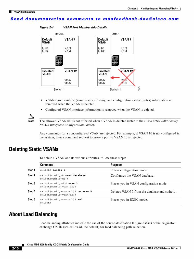
• VSAN attributes and port membership details are maintained by the VSAN manager. This feature is affected when you delete a VSAN from the configuration. When a VSAN is deleted, all the ports in that VSAN are made inactive and the ports are moved to the isolated VSAN. If the same VSAN is recreated, the ports do not automatically get assigned to that VSAN. You must explicitly reconfigure the port VSAN membership (see Figure 2-4)
2-9Cisco MDS 9000 Family NX-OS Fabric Configuration Guide
OL-20706-01, Cisco MDS NX-OS Release 5.0(1a)
Send documenta t ion comments to mdsfeedback -doc@c i sco .com
Chapter 2 Configuring and Managing VSANsVSAN Configuration
Figure 2-4 VSAN Port Membership Details
• VSAN-based runtime (name server), zoning, and configuration (static routes) information is removed when the VSAN is deleted.
• Configured VSAN interface information is removed when the VSAN is deleted.
Note The allowed VSAN list is not affected when a VSAN is deleted (refer to the Cisco MDS 9000 Family NX-OS Interfaces Configuration Guide).
Any commands for a nonconfigured VSAN are rejected. For example, if VSAN 10 is not configured in the system, then a command request to move a port to VSAN 10 is rejected.
Deleting Static VSANsTo delete a VSAN and its various attributes, follow these steps:
About Load BalancingLoad balancing attributes indicate the use of the source-destination ID (src-dst-id) or the originator exchange OX ID (src-dst-ox-id, the default) for load balancing path selection.
DefaultVSAN
fc1/1fc1/2
VSAN 7
fc1/3fc1/4
IsolatedVSAN
VSAN 12
fc1/5fc1/6
Before
DefaultVSAN
fc1/1fc1/2
VSAN 7
fc1/3fc1/4
IsolatedVSAN
fc1/5fc1/6
VSAN 12
fc1/5fc1/6
After
Switch 1 Switch 1 7994
7
Command Purpose
Step 1 switch# config t Enters configuration mode.
Step 2 switch(config)# vsan database switch(config-db)#
Configures the VSAN database.
Step 3 switch-config-db# vsan 2switch(config-vsan-db)#
Places you in VSAN configuration mode.
Step 4 switch(config-vsan-db)# no vsan 5 switch(config-vsan-db)#
Deletes VSAN 5 from the database and switch.
Step 5 switch(config-vsan-db)# endswitch#
Places you in EXEC mode.
2-10Cisco MDS 9000 Family NX-OS Fabric Configuration Guide
OL-20706-01, Cisco MDS NX-OS Release 5.0(1a)

Send documenta t ion comments to mdsfeedback -doc@c i sco .com
Chapter 2 Configuring and Managing VSANsDisplaying Static VSAN Configuration
Configuring Load BalancingTo configure load balancing on an existing VSAN, follow these steps:
About Interop ModeInteroperability enables the products of multiple vendors to come into contact with each other. Fibre Channel standards guide vendors towards common external Fibre Channel interfaces. See the “Switch Interoperability” section on page 12-13.
About FICON VSANsYou can enable FICON in up to eight VSANs. See the “FICON VSAN Prerequisites” section on page 11-7.
Displaying Static VSAN Configuration Use the show vsan command to display information about configured VSANs (see Examples 2-4 to 2-6).
Example 2-4 Displays the Configuration for a Specific VSAN
switch# show vsan 100vsan 100 information name:VSAN0100 state:active in-order guarantee:no interoperability mode:no loadbalancing:src-id/dst-id/oxid
Command Purpose
Step 1 switch# config t Enters configuration mode.
Step 2 switch(config)# vsan databaseswitch(config-vsan-db)#
Enters VSAN database configuration submode
Step 3 switch(config-vsan-db)# vsan 2 Specifies an existing VSAN.
Step 4 switch(config-vsan-db)# vsan 2 loadbalancing src-dst-id
Enables the load balancing guarantee for the selected VSAN and directs the switch to use the source and destination ID for its path selection process.
switch(config-vsan-db)# no vsan 2 loadbalancing src-dst-id
Negates the command issued in the previous step and reverts to the default values of the load balancing parameters.
switch(config-vsan-db)# vsan 2 loadbalancing src-dst-ox-id
Changes the path selection setting to use the source ID, the destination ID, and the OX ID (default).
Step 5 switch(config-vsan-db)# vsan 2 suspend Suspends the selected VSAN.
Step 6 switch(config-vsan-db)# no vsan 2 suspend Negates the suspend command issued in the previous step.
Step 7 switch(config-vsan-db)# endswitch#
Returns you to EXEC mode.
2-11Cisco MDS 9000 Family NX-OS Fabric Configuration Guide
OL-20706-01, Cisco MDS NX-OS Release 5.0(1a)

Send documenta t ion comments to mdsfeedback -doc@c i sco .com
Chapter 2 Configuring and Managing VSANsDefault Settings
Example 2-5 Displays the VSAN Usage
switch# show vsan usage4 vsan configuredconfigured vsans:1-4vsans available for configuration:5-4093
Example 2-6 Displays All VSANs
switch# show vsanvsan 1 information name:VSAN0001 state:active in-order guarantee:no interoperability mode:no loadbalancing:src-id/dst-id/oxid vsan 2 information name:VSAN0002 state:active in-order guarantee:no interoperability mode:no loadbalancing:src-id/dst-id/oxid vsan 7 information name:VSAN0007 state:active in-order guarantee:no interoperability mode:no loadbalancing:src-id/dst-id/oxid vsan 100 information name:VSAN0100 state:active in-order guarantee:no interoperability mode:no loadbalancing:src-id/dst-id/oxid vsan 4094:isolated vsan
Default SettingsTable 2-2 lists the default settings for all configured VSANs.
Table 2-2 Default VSAN Parameters
Parameters Default
Default VSAN VSAN 1.
State Active state.
Name Concatenation of VSAN and a four-digit string representing the VSAN ID. For example, VSAN 3 is VSAN0003.
Load-balancing attribute OX ID (src-dst-ox-id).
2-12Cisco MDS 9000 Family NX-OS Fabric Configuration Guide
OL-20706-01, Cisco MDS NX-OS Release 5.0(1a)

Send documenta t ion comments to mdsfeedback -doc@c i sco .com
Cisco MOL-20706-01, Cisco MDS NX-OS Release 5.0(1a)
C H A P T E R 3
Configuring SAN Device VirtualizationThis chapter describes how to configure virtual devices to represent physical end devices for switches running Cisco MDS SAN-OS Release 3.1(2) and later, or NX-OS Release 4.1(1a) and later.
Cisco SAN device virtualization (SDV) is a licensed feature included in the Cisco MDS 9000 Family Enterprise package (ENTERPRISE_PKG). Refer to the Cisco NX-OS Family Licensing Guide for details about acquiring licenses.
This chapter includes the following sections:
• About SDV, page 3-1
• Configuring SDV, page 3-4
• SDV Requirements and Guidelines, page 3-12
• SDV Configuration Example, page 3-15
• Displaying SDV Information, page 3-17
• Default Settings, page 3-17
About SDVAs of Cisco SAN-OS Release 3.1(2) and later, you can use Cisco SAN device virtualization to create virtual devices that represent physical end-devices. Virtualization of SAN devices accelerates swapout or failover to a replacement disk array, and it also minimizes downtime when replacing host bus adapters (HBAs) or when rehosting an application on a different server.
SAN device virtualization enables you to:
• Reduce the amount of time it takes for data migration, and ultimately the overall amount of downtime.
• Improve ease-of-use and reduce the possibility of user-introduced errors during the failover by performing the operation in a single step.
• Easily scale to larger numbers of targets.
SAN devices that are virtualized can be either initiators or targets. You can virtualize targets to create a virtual target, and also virtualize initiators to create a virtual initiator. Such configurations do not distinguish between virtual initiators and virtual targets (see Figure 3-1 and Figure 3-2).
3-1DS 9000 Family NX-OS Fabric Configuration Guide
Send documenta t ion comments to mdsfeedback -doc@c i sco .com
Chapter 3 Configuring SAN Device VirtualizationAbout SDV
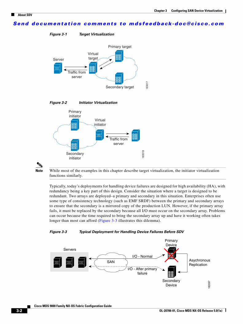
Figure 3-1 Target Virtualization
Figure 3-2 Initiator Virtualization
Note While most of the examples in this chapter describe target virtualization, the initiator virtualization functions similarly.
Typically, today’s deployments for handling device failures are designed for high availability (HA), with redundancy being a key part of this design. Consider the situation where a target is designed to be redundant. Two arrays are deployed–a primary and secondary in this situation. Enterprises often use some type of consistency technology (such as EMF SRDF) between the primary and secondary arrays to ensure that the secondary is a mirrored copy of the production LUN. However, if the primary array fails, it must be replaced by the secondary because all I/O must occur on the secondary array. Problems can occur because the time required to bring the secondary array up and have it working often takes longer than most can afford (Figure 3-3 illustrates this dilemma).
Figure 3-3 Typical Deployment for Handling Device Failures Before SDV
Primary target
Secondary target
Server
Virtualtarget
Traffic fromserver
1830
17
Virtualinitiator
Traffic fromserver
1830
18
Primaryinitiator
Secondaryinitiator
AsychronousReplication
SecondaryDevice
PrimaryDevice
SAN
I/O - Normal
I/O - After primaryfailure
1820
97
Servers
3-2Cisco MDS 9000 Family NX-OS Fabric Configuration Guide
OL-20706-01, Cisco MDS NX-OS Release 5.0(1a)
Send documenta t ion comments to mdsfeedback -doc@c i sco .com
Chapter 3 Configuring SAN Device VirtualizationAbout SDV
If a storage array is replaced without using Cisco SDV, then it may require the following actions:
• Taking down a server to modify zoning and account for the new array.
• Changing the Cisco NX-OS configuration to accommodate Fibre Channel IDs (FC IDs) and pWWNs of the new array.
• Changing a server configuration to accommodate the new FC IDs and pWWNs.
More specifically, without SDV you might experience the following conditions:
• It can take a considerable amount of time to configure a secondary device for a typical production environment.
• In the zoning configuration, all the initiators must be rezoned with the secondary device, and certain initiators must also be reconfigured. For example, the WWN and FC ID of the secondary device are different, so driver files must be changed and the server must be rebooted.
• Clustering (multiple initiators) compounds the problem, and the failover procedure must be repeated for each server of the cluster. Think of a server cluster as a set of HBAs–any storage array FC ID changes must be performed for each HBA.
SDV enables you to achieve the following performance targets:
• Reduce the amount of time it takes for data migration, and ultimately the overall amount of downtime.
• Easily scale to larger numbers of devices.
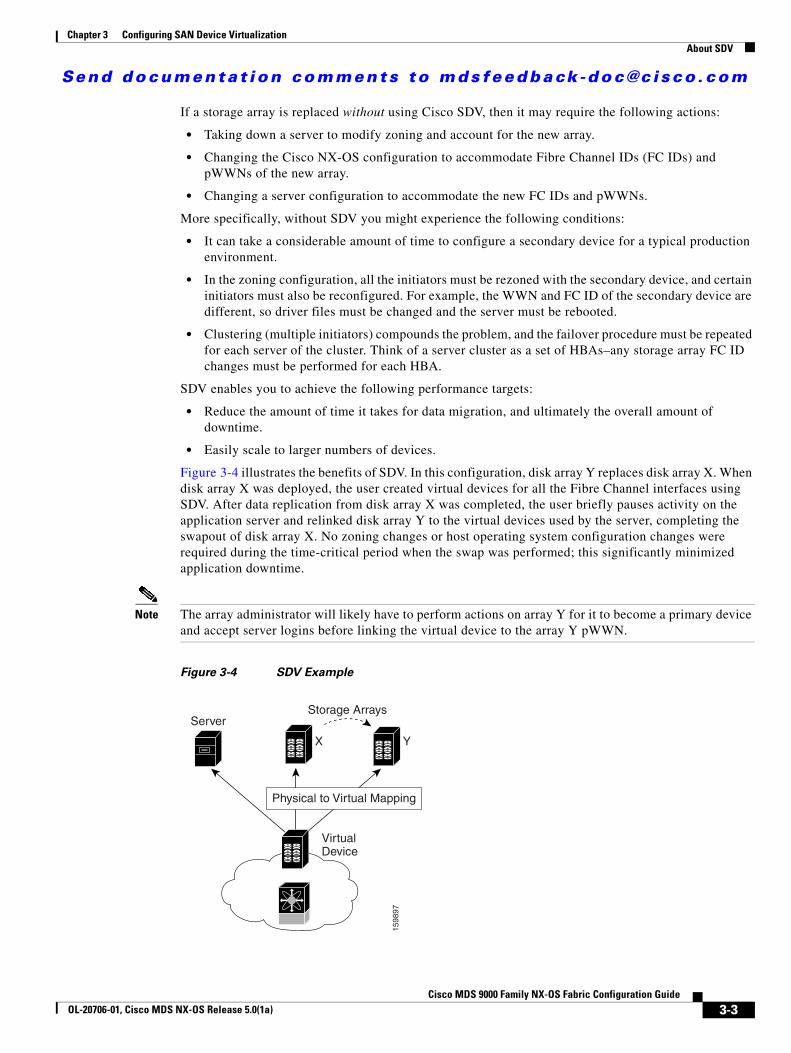
Figure 3-4 illustrates the benefits of SDV. In this configuration, disk array Y replaces disk array X. When disk array X was deployed, the user created virtual devices for all the Fibre Channel interfaces using SDV. After data replication from disk array X was completed, the user briefly pauses activity on the application server and relinked disk array Y to the virtual devices used by the server, completing the swapout of disk array X. No zoning changes or host operating system configuration changes were required during the time-critical period when the swap was performed; this significantly minimized application downtime.
Note The array administrator will likely have to perform actions on array Y for it to become a primary device and accept server logins before linking the virtual device to the array Y pWWN.
Figure 3-4 SDV Example
1598
97
Server
VirtualDevice
Storage Arrays
X Y
Physical to Virtual Mapping
3-3Cisco MDS 9000 Family NX-OS Fabric Configuration Guide
OL-20706-01, Cisco MDS NX-OS Release 5.0(1a)

Send documenta t ion comments to mdsfeedback -doc@c i sco .com
Chapter 3 Configuring SAN Device VirtualizationConfiguring SDV
Key ConceptsThe following terms are used throughout this chapter:
• Virtual device—The virtualized or proxy representation of the real device, which is registered with the name server and has a pWWN and FC ID. A virtual device exists as long as its real (physical) counterpart is online. The virtual device pWWN and FC ID must be unique and cannot clash with any real device pWWNs and FC IDs.
• Virtual domain—Reserved by SDV to assign FC IDs to virtual devices. If the switch that reserved the domain goes down, another switch takes over its role using the same domain.
• Primary device—The device that is configured as primary. By default, the primary device becomes the active device if it is online.
• Secondary device—The additional device that is configured. By default, the secondary device is standby.
• Active device—The device that is currently virtualized is called the active device. By default, the primary device becomes the active device if it is online. The active device is indicated by a (*) symbol.
Automatic Failover and FallbackAs of Cisco MDS NX-OS Release 4.1(1a), SAN device virtualization supports automatic failover and fallback configurations for the virtual devices. In all of the earlier releases, when there was a failure, you needed to manually configure the device as primary to make it active. With the introduction of automatic failover and fallback configurations, the active device is distinguished from the primary device indicated by a (*) symbol.
• Auto failover—When there is a failure, the failover auto attribute automatically shuts down the primary device and brings up the secondary device to active state. When the primary device comes back online, it requires user intervention to switchover.
• Auto failover with fallback—In addition to automatic failover, when the primary device comes back online after a failover, the primary device is brought to active state and the secondary device moved to standby state.
To configure automatic failover, use the attribute failover auto command in SAN device virtualization configuration mode. To configure automatic failover and fallback, use the attribute failover auto fallback command. To identify the active device, use the show sdv database command.
Configuring SDVSDV is a distributed service and uses Cisco Fabric Services (CFS) distribution to synchronize the databases. When you configure SDV, it starts a CFS session and locks the fabric. When a fabric is locked, Cisco NX-OS software does not allow any configuration changes from a switch other than the switch holding the lock and issues a message to inform users about the locked status. Configuration changes are held in a pending database for the application. You must perform a commit operation to make the configuration active and to release the lock for all switches. You can discard or stop changes from being distributed by entering the abort or clear command.
Refer to the Cisco MDS 9000 Family NX-OS System Management Configuration Guide for more details about CFS.
3-4Cisco MDS 9000 Family NX-OS Fabric Configuration Guide
OL-20706-01, Cisco MDS NX-OS Release 5.0(1a)

Send documenta t ion comments to mdsfeedback -doc@c i sco .com
Chapter 3 Configuring SAN Device VirtualizationConfiguring SDV
Note When you enable SDV, CFS distribution is also enabled; CFS distribution cannot be disabled for SDV.
The following sections describe how to configure SDV:
• Configuring a Virtual Device, page 3-5
• Configuring a Zone for a Virtual Device, page 3-7
• Linking a Virtual Device with a Physical Device, page 3-10
• Configuring LUN Zone Members for SDV Devices, page 3-11
• member device-alias VT2 lun 1Resolving Fabric Merge Conflicts, page 3-12
Configuring a Virtual DeviceA virtual device is identified by an alphanumeric name of up to 32 characters and defines all the real devices (one primary and one or more secondary) that it represents. Upon the successful creation of a virtual device, the virtual device name is internally registered as the device alias name with the device alias database; the pWWN is automatically assigned by the system using Cisco Organizational Unique Identifier (OUI). A virtual device appears as a real, physical device. You can enumerate up to 128 devices for a virtual device. There is a limit of 4095 on the number of virtual devices that you can create in a single VSAN.
Note As of Cisco MDS SAN-OS Release 3.1(2) and NX-OS Release 4.1(1a), SDV supports up to 1024 virtual devices per VSAN.
Figure 3-5 shows a configuration that includes a new virtual device, vt1.
Figure 3-5 Creating a Virtual Device
Primary Secondary
VirtualDevice
SAN DeviceVirtualization
VT
vtpwwnvt1
t2pwwnt2
t1pwwnt1
1599
00
i1pwwni1
i2pwwni2
i3pwwni3
3-5Cisco MDS 9000 Family NX-OS Fabric Configuration Guide
OL-20706-01, Cisco MDS NX-OS Release 5.0(1a)

Send documenta t ion comments to mdsfeedback -doc@c i sco .com
Chapter 3 Configuring SAN Device VirtualizationConfiguring SDV
To configure a virtual device and commit it to the fabric configuration, follow these steps:
As of MDS NX-OS Release 4.1(1a), the following conditions must be considered when configuring the virtual device failover attributes:
• The attribute configuration is supported only with MDS NX-OS Release 4.1(1a) and later. In a mixed mode fabric where earlier releases are combined, the attribute configuration will fail.
• When the failover attribute is configured, if the primary device is offline then the secondary device becomes active.
• When the failover attribute is deleted after the primary device failover to the secondary device, then the primary becomes active if the primary device is online. If the primary device is not online, then the SDV virtual device is shut down.
This example shows the virtual device status without automatic failover configurations:
switch# show sdv databasesdv virtual-device name vdev1 vsan 1[ WWN:50:00:53:04:48:3c:01 FCID:0x42000c Real-FCID:0xeb0001 ] * device-alias dev1 primary device-alias dev2
Command Purpose
Step 1 switch# config tswitch(config)#
Enters configuration mode.
Step 2 switch(config)# feature sdv Enables the SDV feature.
Note If you do not have the Cisco MDS 9000 Family Enterprise package license (ENTERPRISE_PKG) installed, this command will fail.
Step 3 switch(config)# sdv virtual-device name vdev1 vsan 2
Configures a virtual device alias name (vdev1).
Enters SDV manager configuration submode.
Step 4 switch(config-sdv-virt-dev)# pwwn 21:00:00:04:cf:cf:45:40 primary
switch(config-sdv-virt-dev)# pwwn 21:00:00:04:cf:cf:38:d6
Maps primary virtual device to the pWWN of real devices.
Maps secondary virtual device to pWWN of a real device.
Step 5 switch(config-sdv-virt-dev)# attribute failover auto
switch(config-sdv-virt-dev)# attribute failover auto fallback
(Optional) Automatically fails over from primary device to the secondary device.
(Optional) Automatically fails over, and then falls back to the primary device when the primary device comes online.
Step 6 switch(config-sdv-virt-dev)# exit Exits SDV manager configuration submode.
Step 7 switch(config)# sdv commit vsan 2 Commits the VSAN configuration to the fabric.
Step 8 switch(config)# exitswitch# show device-alias database
Verifies that the virtualized device is registered in the device alias database.
Step 9 switch# show fcns database vsan vsan 2 If the primary device is online, verifies that the virtual device appears in the name server database and has the correct FC4 type (Fibre Channel Layer 4).
3-6Cisco MDS 9000 Family NX-OS Fabric Configuration Guide
OL-20706-01, Cisco MDS NX-OS Release 5.0(1a)
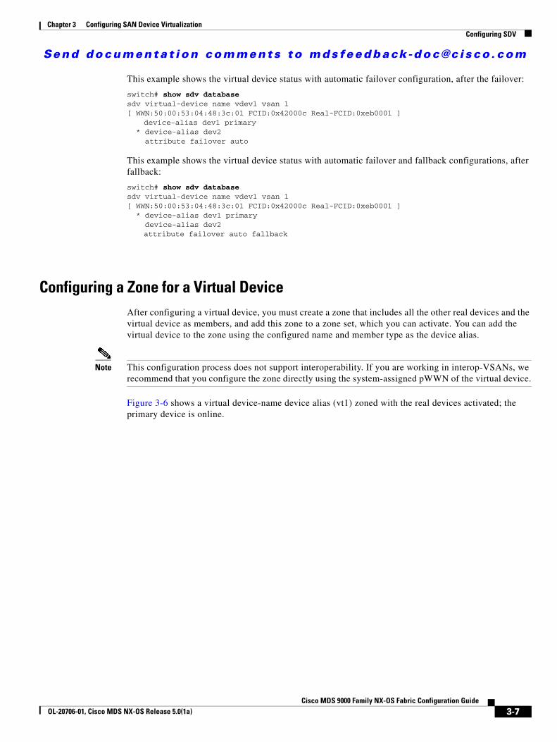
Send documenta t ion comments to mdsfeedback -doc@c i sco .com
Chapter 3 Configuring SAN Device VirtualizationConfiguring SDV
This example shows the virtual device status with automatic failover configuration, after the failover:
switch# show sdv databasesdv virtual-device name vdev1 vsan 1[ WWN:50:00:53:04:48:3c:01 FCID:0x42000c Real-FCID:0xeb0001 ]
device-alias dev1 primary * device-alias dev2 attribute failover auto
This example shows the virtual device status with automatic failover and fallback configurations, after fallback:
switch# show sdv databasesdv virtual-device name vdev1 vsan 1[ WWN:50:00:53:04:48:3c:01 FCID:0x42000c Real-FCID:0xeb0001 ] * device-alias dev1 primary device-alias dev2
attribute failover auto fallback
Configuring a Zone for a Virtual DeviceAfter configuring a virtual device, you must create a zone that includes all the other real devices and the virtual device as members, and add this zone to a zone set, which you can activate. You can add the virtual device to the zone using the configured name and member type as the device alias.
Note This configuration process does not support interoperability. If you are working in interop-VSANs, we recommend that you configure the zone directly using the system-assigned pWWN of the virtual device.
Figure 3-6 shows a virtual device-name device alias (vt1) zoned with the real devices activated; the primary device is online.
3-7Cisco MDS 9000 Family NX-OS Fabric Configuration Guide
OL-20706-01, Cisco MDS NX-OS Release 5.0(1a)

Send documenta t ion comments to mdsfeedback -doc@c i sco .com
Chapter 3 Configuring SAN Device VirtualizationConfiguring SDV
Figure 3-6 Zoning the Virtual Device with Real Devices
To add the virtual device to a zone as a zone member, follow these steps:
1599
01Primary Secondary
VirtualDevice
SAN DeviceVirtualization
SAN Device Virtualization Zone
vtpwwnvt1
t2pwwnt2
t1pwwnt1
i1pwwni1
i2pwwni2
i3pwwni3
Command Purpose
Step 1 switch# config t Enters configuration mode.
Step 2 switch(config)# zoneset name zs1 vsan 1 Groups zones under one zone set named zs1 in the VSAN, vsan 1. Enters zone set submode.
Step 3 switch(config-zoneset)# zone name zone1 Creates the zone zone1.
Step 4 switch(config-zoneset-zone)# member device-alias vdev1orswitch (config-zoneset-zone)# member pwwn 50:00:53:00:01:fa:70:09
Adds a virtual device (vdev1) as device-alias type zone member to the zone.
Alternatively, adds a virtual device as pWWN type zone member to the zone.
Step 5 switch(config-zoneset-zone)# member pwwn 21:22:5:d8:15:11:8:8
Adds the real device to the zone.
Step 6 switch(config-zoneset-zone)# end Exits all modes.
Step 7 switch# show zoneset Displays the zone sets configured for the VSAN, vsan 1, in step 4, as well as the primary and secondary pWWNs.
Step 8 switch# config t Enters configuration mode.
Step 9 switch(config)# zoneset activate name zs1 vsan 1
Activates the new zone, zs1 for the VSAN, vsan1.
Step 10 switch(config)# end Exits all modes.
Step 11 switch# show zoneset active vsan 1 Displays the active zone for the VSAN, vsan1. Confirms the zone set and zone names.
3-8Cisco MDS 9000 Family NX-OS Fabric Configuration Guide
OL-20706-01, Cisco MDS NX-OS Release 5.0(1a)
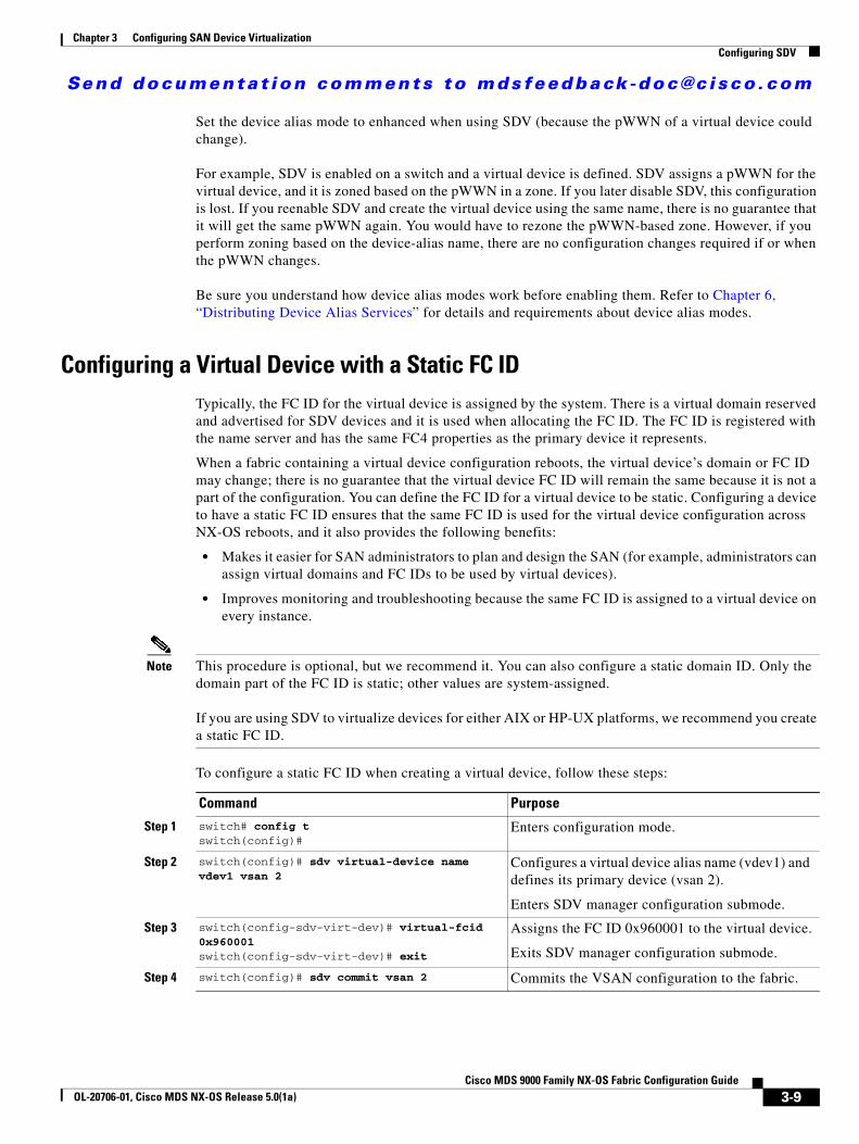
Send documenta t ion comments to mdsfeedback -doc@c i sco .com
Chapter 3 Configuring SAN Device VirtualizationConfiguring SDV
Set the device alias mode to enhanced when using SDV (because the pWWN of a virtual device could change).
For example, SDV is enabled on a switch and a virtual device is defined. SDV assigns a pWWN for the virtual device, and it is zoned based on the pWWN in a zone. If you later disable SDV, this configuration is lost. If you reenable SDV and create the virtual device using the same name, there is no guarantee that it will get the same pWWN again. You would have to rezone the pWWN-based zone. However, if you perform zoning based on the device-alias name, there are no configuration changes required if or when the pWWN changes.
Be sure you understand how device alias modes work before enabling them. Refer to Chapter 6, “Distributing Device Alias Services” for details and requirements about device alias modes.
Configuring a Virtual Device with a Static FC IDTypically, the FC ID for the virtual device is assigned by the system. There is a virtual domain reserved and advertised for SDV devices and it is used when allocating the FC ID. The FC ID is registered with the name server and has the same FC4 properties as the primary device it represents.
When a fabric containing a virtual device configuration reboots, the virtual device’s domain or FC ID may change; there is no guarantee that the virtual device FC ID will remain the same because it is not a part of the configuration. You can define the FC ID for a virtual device to be static. Configuring a device to have a static FC ID ensures that the same FC ID is used for the virtual device configuration across NX-OS reboots, and it also provides the following benefits:
• Makes it easier for SAN administrators to plan and design the SAN (for example, administrators can assign virtual domains and FC IDs to be used by virtual devices).
• Improves monitoring and troubleshooting because the same FC ID is assigned to a virtual device on every instance.
Note This procedure is optional, but we recommend it. You can also configure a static domain ID. Only the domain part of the FC ID is static; other values are system-assigned.
If you are using SDV to virtualize devices for either AIX or HP-UX platforms, we recommend you create a static FC ID.
To configure a static FC ID when creating a virtual device, follow these steps:
Command Purpose
Step 1 switch# config tswitch(config)#
Enters configuration mode.
Step 2 switch(config)# sdv virtual-device name vdev1 vsan 2
Configures a virtual device alias name (vdev1) and defines its primary device (vsan 2).
Enters SDV manager configuration submode.
Step 3 switch(config-sdv-virt-dev)# virtual-fcid 0x960001switch(config-sdv-virt-dev)# exit
Assigns the FC ID 0x960001 to the virtual device.
Exits SDV manager configuration submode.
Step 4 switch(config)# sdv commit vsan 2 Commits the VSAN configuration to the fabric.
3-9Cisco MDS 9000 Family NX-OS Fabric Configuration Guide
OL-20706-01, Cisco MDS NX-OS Release 5.0(1a)
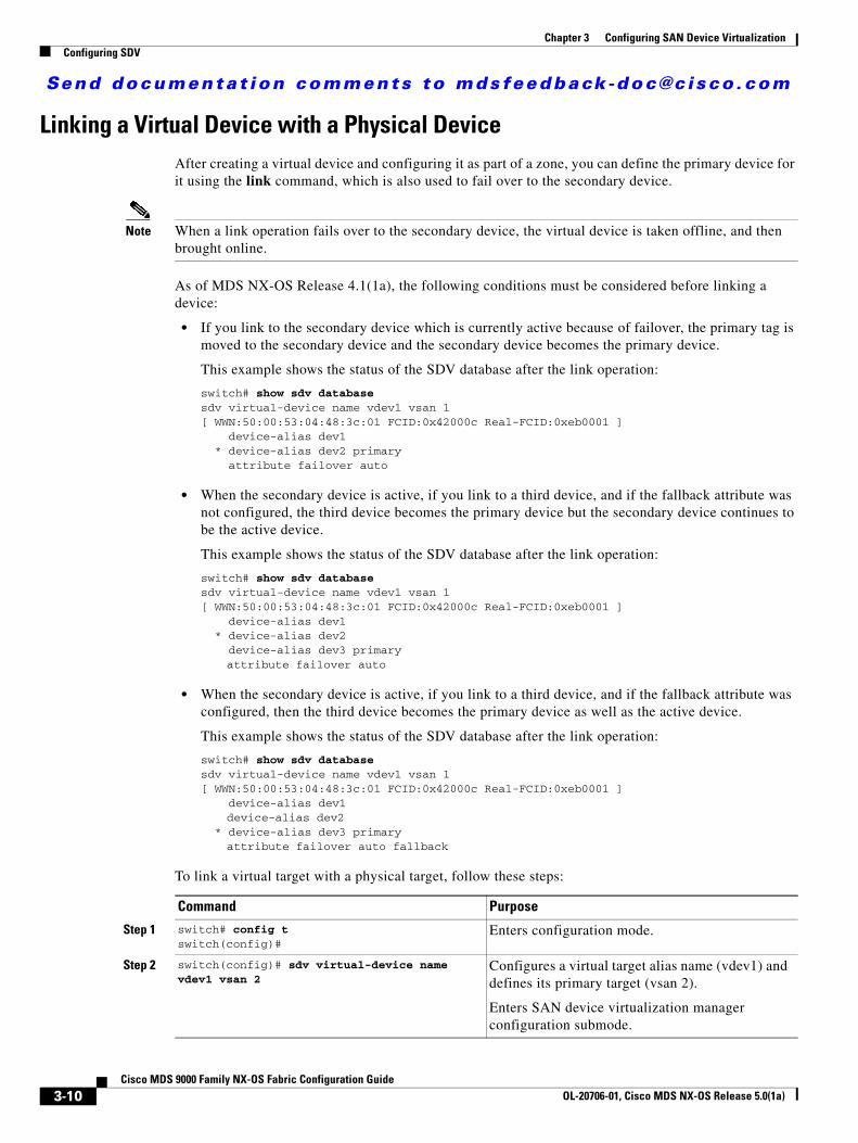
Send documenta t ion comments to mdsfeedback -doc@c i sco .com
Chapter 3 Configuring SAN Device VirtualizationConfiguring SDV
Linking a Virtual Device with a Physical DeviceAfter creating a virtual device and configuring it as part of a zone, you can define the primary device for it using the link command, which is also used to fail over to the secondary device.
Note When a link operation fails over to the secondary device, the virtual device is taken offline, and then brought online.
As of MDS NX-OS Release 4.1(1a), the following conditions must be considered before linking a device:
• If you link to the secondary device which is currently active because of failover, the primary tag is moved to the secondary device and the secondary device becomes the primary device.
This example shows the status of the SDV database after the link operation:
switch# show sdv databasesdv virtual-device name vdev1 vsan 1[ WWN:50:00:53:04:48:3c:01 FCID:0x42000c Real-FCID:0xeb0001 ] device-alias dev1 * device-alias dev2 primary attribute failover auto
• When the secondary device is active, if you link to a third device, and if the fallback attribute was not configured, the third device becomes the primary device but the secondary device continues to be the active device.
This example shows the status of the SDV database after the link operation:
switch# show sdv databasesdv virtual-device name vdev1 vsan 1[ WWN:50:00:53:04:48:3c:01 FCID:0x42000c Real-FCID:0xeb0001 ] device-alias dev1 * device-alias dev2 device-alias dev3 primary
attribute failover auto
• When the secondary device is active, if you link to a third device, and if the fallback attribute was configured, then the third device becomes the primary device as well as the active device.
This example shows the status of the SDV database after the link operation:
switch# show sdv databasesdv virtual-device name vdev1 vsan 1[ WWN:50:00:53:04:48:3c:01 FCID:0x42000c Real-FCID:0xeb0001 ] device-alias dev1
device-alias dev2 * device-alias dev3 primary
attribute failover auto fallback
To link a virtual target with a physical target, follow these steps:
Command Purpose
Step 1 switch# config tswitch(config)#
Enters configuration mode.
Step 2 switch(config)# sdv virtual-device name vdev1 vsan 2
Configures a virtual target alias name (vdev1) and defines its primary target (vsan 2).
Enters SAN device virtualization manager configuration submode.
3-10Cisco MDS 9000 Family NX-OS Fabric Configuration Guide
OL-20706-01, Cisco MDS NX-OS Release 5.0(1a)

Send documenta t ion comments to mdsfeedback -doc@c i sco .com
Chapter 3 Configuring SAN Device VirtualizationConfiguring SDV
Configuring LUN Zone Members for SDV DevicesYou can configure LUN zone members for SDV devices. Following are the types of SDV LUN zone configurations for existing real devices and configured SDV devices:
• Real initiator (I1)
• Real target (T1) supporting LUNs from 0 to 12
• Virtual target (VT1) virtualizing the real target (T1)
• Virtual initiator (VI1) virtualizing real initiator (I1)
Real Initiator and SDV Virtual Target with LUN
In Example 3-1 a real initiator is zoned with an SDV virtual target (including the LUN).
Example 3-1 Real Initiator and SDV Virtual Target with LUN
zoneset name zs1 vsan 2zone name z1 vsan 2
member device-alias I1member device-alias VT1 lun 0member device-alias VT2 lun 1
SDV Virtual Initiator and Real Target with LUN
In Example 3-2 an SDV virtual initiator is zoned with a real target (including the LUN).
Example 3-2 SDV Virtual Initiator and Real Target with LUN
zoneset name zs2 vsan 1zone name z2 vsan 1
member device-alias VI1member device-alias T1 lun 0member device-alias T2 lun 1
SDV Virtual Initiator and SDV Virtual Target with LUN
In Example 3-3 an SDV virtual initiator is zoned with an SDV virtual target (including the LUN).
Example 3-3
zoneset name zs3 vsan 1zone name z3 vsan 1
member device-alias VI1
Step 3 switch(config-sdv-virt-dev)# link pwwn 21:00:00:04:cf:cf:45:40 vsan 2
switch(config-sdv-virt-dev)# exit
Links the virtual target pWWN to a physical target.
Exits SAN device virtualization manager submode.
Step 4 switch(config)# sdv commit vsan 2 Commits the VSAN configuration to the fabric.
Command Purpose
3-11Cisco MDS 9000 Family NX-OS Fabric Configuration Guide
OL-20706-01, Cisco MDS NX-OS Release 5.0(1a)

Send documenta t ion comments to mdsfeedback -doc@c i sco .com
Chapter 3 Configuring SAN Device VirtualizationSDV Requirements and Guidelines
member device-alias VT1 lun 0
member device-alias VT2 lun 1Resolving Fabric Merge ConflictsWhenever two fabrics merge SDV merges its database. A merge conflict can occur when there is a run-time information conflict or configuration mismatch. Run-time conflicts can occur due to:
• Identical pWWNs being assigned to different virtual devices
• The same virtual devices are assigned different pWWNs.
• The virtual device and virtual FC ID are mismatched.
A blank commit is a commit operation that does not contain configuration changes, and enforces the SDV configuration of the committing switch fabric-wide. A blank commit operation resolves merge conflicts by pushing the configuration from the committing switch throughout the fabric, which reinitializes the conflicting virtual devices. Exercise caution while performing this operation, as it can easily take some virtual devices offline.
Merge failures resulting from a pWWN conflict can cause a failure with the device alias as well. A blank commit operation on a merge-failed VSAN within SDV should resolve the merge failure in the device alias.
You can avoid merge conflicts due to configuration mismatch by ensuring that:
• The pWWN and device alias entries for a virtual device are identical (in terms of primary and secondary).
• There are no virtual device name conflicts across VSANs in fabrics.
SDV Requirements and GuidelinesBe aware of the following requirements and guidelines as you plan and configure SDV:
• SDV should be enabled on switches where devices that are part of SDV zones are connected.
• SDV does not work for devices connected to non-MDS switches.
• Broadcast zoning is not supported for a zone with a virtual device.
• IVR and SDV cannot be used for the same device. A SDV-virtualized device cannot be part of a IVR zone or zoneset.
• Virtual device names should be unique across VSANs because they are registered with the device alias server, which is unaware of VSANs. For example, if you have enabled SDV and have registered a name, vt1 in both VSAN 1 and VSAN 2, then the device alias server cannot store both entries because they have the same name.
• You cannot specify the same primary device for different virtual devices.
• SDV does not work with soft zoning (Soft zoning means that zoning restrictions are applied only during interaction between the name server and the end device. If an end device somehow knows the FC ID of a device outside its zone, it can access that device), nor does it work with the zone default-zone permit vsan operation (which would otherwise permit or deny traffic to members in the default zone).
• If devices are not already zoned with the initiators, then you can configure SDV virtual device zones with no negative impact. If they are already zoned, then zoning changes are required.
3-12Cisco MDS 9000 Family NX-OS Fabric Configuration Guide
OL-20706-01, Cisco MDS NX-OS Release 5.0(1a)
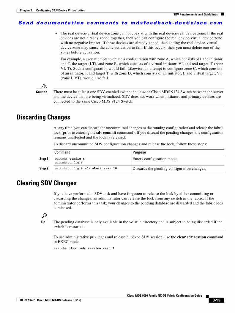
Send documenta t ion comments to mdsfeedback -doc@c i sco .com
Chapter 3 Configuring SAN Device VirtualizationSDV Requirements and Guidelines
• The real device-virtual device zone cannot coexist with the real device-real device zone. If the real devices are not already zoned together, then you can configure the real device-virtual device zone with no negative impact. If these devices are already zoned, then adding the real device-virtual device zone may cause the zone activation to fail. If this occurs, then you must delete one of the zones before activation.
For example, a user attempts to create a configuration with zone A, which consists of I, the initiator, and T, the target (I,T), and zone B, which consists of a virtual initiator, VI, and real target, T (zone VI, T). Such a configuration would fail. Likewise, an attempt to configure zone C, which consists of an initiator, I, and target T, with zone D, which consists of an initiator, I, and virtual target, VT (zone I, VT), would also fail.
Caution There must be at least one SDV-enabled switch that is not a Cisco MDS 9124 Switch between the server and the device that are being virtualized. SDV does not work when initiators and primary devices are connected to the same Cisco MDS 9124 Switch.
Discarding ChangesAt any time, you can discard the uncommitted changes to the running configuration and release the fabric lock (prior to entering the sdv commit command). If you discard the pending changes, the configuration remains unaffected and the lock is released.
To discard uncommitted SDV configuration changes and release the lock, follow these steps:
Clearing SDV ChangesIf you have performed a SDV task and have forgotten to release the lock by either committing or discarding the changes, an administrator can release the lock from any switch in the fabric. If the administrator performs this task, your changes to the pending database are discarded and the fabric lock is released.
Tip The pending database is only available in the volatile directory and is subject to being discarded if the switch is restarted.
To use administrative privileges and release a locked SDV session, use the clear sdv session command in EXEC mode.
switch# clear sdv session vsan 2
Command Purpose
Step 1 switch# config tswitch(config)#
Enters configuration mode.
Step 2 switch(config)# sdv abort vsan 10 Discards the pending configuration changes.
3-13Cisco MDS 9000 Family NX-OS Fabric Configuration Guide
OL-20706-01, Cisco MDS NX-OS Release 5.0(1a)
Send documenta t ion comments to mdsfeedback -doc@c i sco .com
Chapter 3 Configuring SAN Device VirtualizationSDV Requirements and Guidelines
Guidelines for Downgrading SDVAs of MDS NX-OS Release 4.1(1a), SDV supports failover and fallback attribute configuration. Downgrading to an earlier release requires you to remove the attribute configurations before downgrading.
As of SAN-OS Release 3.1(3), SDV supports virtual initiators and LUN zoning. Consequently, in SAN-OS Releases 3.1(3) and later, if virtual initiators are configured or SDV devices are configured as LUN-based members of a zone, a configuration check will indicate that downgrading to SAN-OS Release 3.1(2) may be disruptive and is therefore not recommended.
Downgrading with Attributes Configured
As of MDS NX-OS Release 4.1(1a), SDV supports failover and fallback attribute configuration. To successfully downgrade to an earlier release, you must remove the attribute configurations before downgrading.
Downgrading with Virtual Initiators Configured
If SDV virtual initiators are configured, you will be unable to downgrade to SAN-OS Release 3.1(2).
This incompatibility only warns before a downgrade. We recommend that you remove the virtual initiator configuration or shut down the initiator port so that there are no inconsistencies in the downgraded version.
Note We also recommend that you trigger a manual discovery on all the switches before configuring the virtual initiators; in fact, you can trigger the discovery before proceeding to the downgrade by entering the following commands:switch# discover scsi-target local os all
discovery started
switch# discover scsi-target remote os all
discovery started
switch#
Downgrading with SDV LUN Zoning Configured
Following are the downgrade scenarios when SDV LUN zoning is configured:
• Real initiator and SDV virtual target with LUN
• SDV virtual initiator and real target with LUN
• SDV virtual initiator and SDV virtual target with LUN
In each of these cases, a configuration check is registered to prevent users from downgrading to SAN-OS Release 3.1(2). This incompatibility will be disruptive if you proceed with the downgrade.
To avoid the configuration check, delete all the LUN zone members from SDV zones, and then activate the zone set before the downgrade.
3-14Cisco MDS 9000 Family NX-OS Fabric Configuration Guide
OL-20706-01, Cisco MDS NX-OS Release 5.0(1a)

Send documenta t ion comments to mdsfeedback -doc@c i sco .com
Chapter 3 Configuring SAN Device VirtualizationSDV Configuration Example
SDV Configuration ExampleThe following example shows all tasks (required and optional) associated with configuring SDV:
Step 1 Enter configuration mode.
switch# config tEnter configuration commands, one per line. End with CNTL/Z.
Step 2 Enable SDV.
switch(config)# feature sdv
Step 3 Locate the pWWNs of the devices in the VSAN (vsan 2). Record the pWWNs, as you will need them in the next step when you create a virtual device.
switch(config)# do show fcns database vsan 2VSAN 2:--------------------------------------------------------------------------FCID TYPE PWWN (VENDOR) FC4-TYPE:FEATURE--------------------------------------------------------------------------0x9f0201 NL 21:00:00:04:cf:cf:45:40 (Seagate) scsi-fcp0x9f0423 NL 21:00:00:04:cf:cf:38:d6 (Seagate) scsi-fcp
Total number of entries = 2
Step 4 Create a virtual device (vdev1) for the VSAN and specify both the primary and secondary pWWNs.
switch(config)# sdv virtual-device name vdev1 vsan 2switch(config-sdv-virt-dev)# pwwn 21:00:00:04:cf:cf:45:40 primaryswitch(config-sdv-virt-dev)# pwwn 21:00:00:04:cf:cf:38:d6
Step 5 Configure automatic failover and fallback attributes.
switch(config-sdv-virt-dev)# attribute failover autoswitch(config-sdv-virt-dev)# attribute failover auto fallback
Step 6 Create a static FC ID for the target device.
switch(config-sdv-virt-dev)# virtual-fcid 0x960001switch(config-sdv-virt-dev)# exit
Step 7 Commit the new virtual device configuration to the fabric.
switch(config)# sdv commit vsan 2switch(config)# exit
Step 8 Enter the show sdv database command, which displays the primary and secondary virtual devices created when you configured the virtual device in the VSAN (vsan 2). Ensure that the virtual device name, pWWNs, and FC ID are correct.
switch# show sdv database vsan 2sdv virtual-device name vdev1 vsan 2[ WWN:50:00:53:00:00:d2:e0:01 FCID:0x960001 Real-FCID:0x9f0201 ] virtual-fcid 0x960001* pwwn 21:00:00:04:cf:cf:45:40 primary pwwn 21:00:00:04:cf:cf:38:d6
Step 9 Enter the show device-alias database command, which displays the contents of the device alias database. Ensure that the new virtual device name appears and that the name is correct.
switch# show device-alias database
3-15Cisco MDS 9000 Family NX-OS Fabric Configuration Guide
OL-20706-01, Cisco MDS NX-OS Release 5.0(1a)

Send documenta t ion comments to mdsfeedback -doc@c i sco .com
Chapter 3 Configuring SAN Device VirtualizationSDV Configuration Example
device-alias name vdev1 pwwn 50:00:53:00:01:c9:70:01
Total number of entries = 1
Step 10 Create a zone member under one zone set named zs1 in the VSAN (vsan 2) and add the virtual target device to the new zone using the device alias member type. Before activating the new zone, display the zoneset information to ensure that the zoneset name, zone name, and pWWNs are correct.
switch# config tEnter configuration commands, one per line. End with CNTL/Z.switch(config)# zoneset name zs1 vsan 2switch(config-zoneset)# zone name zzz1switch(config-zoneset-zone)# member device-alias vdev1switch(config-zoneset-zone)# member pwwn 21:00:03:04:55:cf:d6:40switch(config-zoneset-zone)# endswitch# show zonesetzoneset name zs1 vsan 2 zone name zzz1 vsan 2 pwwn 50:00:53:00:01:c9:70:01 [vdev1] pwwn 21:00:03:04:55:cf:d6:40
Step 11 Activate the new zone configuration.
switch(config)# zoneset activate name zs1 vsan 2Zoneset activation initiated. check zone statusswitch(config)# exit
Step 12 Display the active zoneset to ensure the data in the new zone configuration is correct. Also confirm that the pWWNs are correct.
switch# show zoneset active vsan 2zoneset name zs1 vsan 2 zone name zzz1 vsan 2 * fcid 0x211324 [pwwn 50:00:53:00:01:c9:70:01] [vdev1] pwwn 21:00:03:04:55:cf:d6:40
switch# show sdv database vsan 2sdv virtual-device name vdev1 vsan 2[ WWN:50:00:53:00:00:d2:e0:01 FCID:0x960001 Real-FCID:0x9f0201 ] virtual-fcid 0x960001* pwwn 21:00:00:04:cf:cf:45:40 primary pwwn 21:00:00:04:cf:cf:38:d6
Step 13 Enter the SDV manager configuration submode and display the pWWNs for the virtual devices in vsan 2. After making a note of the pWWNs, migrate the primary virtual device to the secondary device, link this new primary device to a physical device, and then commit this configuration to the fabric. Confirm that the secondary virtual device is now the primary.
switch# conf t
switch(config-sdv-virt-dev)# link pwwn 21:00:00:04:cf:cf:38:d6switch(config-sdv-virt-dev)# exitswitch(config)# sdv commit vsan 2switch(config)# do show sdv database vsan 2sdv virtual-device name vdev1 vsan 2[ WWN:50:00:53:00:00:d2:e0:01 FCID:0x960001 Real-FCID:0x9f0423 ] virtual-fcid 0x960001 pwwn 21:00:00:04:cf:cf:45:40* pwwn 21:00:00:04:cf:cf:38:d6 primary
virtual-device name vdev2 vsan 2[ WWN:50:00:53:00:00:0b:50:01 ]
3-16Cisco MDS 9000 Family NX-OS Fabric Configuration Guide
OL-20706-01, Cisco MDS NX-OS Release 5.0(1a)

Send documenta t ion comments to mdsfeedback -doc@c i sco .com
Chapter 3 Configuring SAN Device VirtualizationDisplaying SDV Information
Displaying SDV InformationTo display the results of the last commit to the SDV database, enter this command:
switch# show sdv session status vsan 1Session Parameters for VSAN: 1-------------------------------Last Action Time Stamp : Fri Feb 2 10:17:20 2007Last Action : CommitLast Action Result : SuccessLast Action Failure Reason : none
To display the results of the last CFS SDV fabric merge for a VSAN, enter this command:
switch# show sdv merge status vsan 1Merge Status for VSAN : 1-----------------------------Last Merge Time Stamp : NoneLast Merge State : NoneLast Merge Result : SUCCESSLast Merge Failure Reason: None [cfs_status: 0]
To display details about the SDV database, enter this command:
switch# show sdv database vsan 2sdv virtual-device name vdev1 vsan 2[ WWN:50:00:53:00:00:d2:e0:01 FCID:0x960001 Real-FCID:0x9f0201 ] virtual-fcid 0x960001* pwwn 21:00:00:04:cf:cf:45:40 primary pwwn 21:00:00:04:cf:cf:38:d6
To display statistics about SDV for a VSAN, enter this command:
switch# show sdv statistics vsan 1VSAN ELS-CMD Requests Accepts Rejects Drops-------------------------------------------------1 ELS_PLOGI 54 54 0 01 ELS_RRQ 2 2 0 01 ELS_PRLI 54 54 0 0
Default SettingsTable 3-1 lists the default settings for SDV parameters.
Table 3-1 Default SDV Configuration Parameters
Parameters Default
enable disabled
3-17Cisco MDS 9000 Family NX-OS Fabric Configuration Guide
OL-20706-01, Cisco MDS NX-OS Release 5.0(1a)

Send documenta t ion comments to mdsfeedback -doc@c i sco .com
Chapter 3 Configuring SAN Device VirtualizationDefault Settings
3-18Cisco MDS 9000 Family NX-OS Fabric Configuration Guide
OL-20706-01, Cisco MDS NX-OS Release 5.0(1a)

Send documenta t ion comments to mdsfeedback -doc@c i sco .com
Cisco MOL-20706-01, Cisco MDS NX-OS Release 5.0(1a)
C H A P T E R 4
Creating Dynamic VSANsThis chapter includes the following sections:
• About DPVM, page 4-1
• DPVM Database Distribution, page 4-5
• Database Merge Guidelines, page 4-8
• Displaying DPVM Configurations, page 4-10
• Sample DPVM Configuration, page 4-11
• Default Settings, page 4-14
About DPVMPort VSAN membership on the switch is assigned on a port-by-port basis. By default each port belongs to the default VSAN.
You can dynamically assign VSAN membership to ports by assigning VSANs based on the device WWN. This method is referred to as Dynamic Port VSAN Membership (DPVM). DPVM offers flexibility and eliminates the need to reconfigure the port VSAN membership to maintain fabric topology when a host or storage device connection is moved between two Cisco MDS switches or two ports within a switch. It retains the configured VSAN regardless of where a device is connected or moved. To assign VSANs statically, see Chapter 2, “Configuring and Managing VSANs.”
DPVM configurations are based on port world wide name (pWWN) and node world wide name (nWWN) assignments. A DPVM database contains mapping information for each device pWWN/nWWN assignment and the corresponding VSAN. The Cisco NX-OS software checks the database during a device FLOGI and obtains the required VSAN details.
The pWWN identifies the host or device and the nWWN identifies a node consisting of multiple devices. You can assign any one of these identifiers or any combination of these identifiers to configure DPVM mapping. If you assign a combination, then preference is given to the pWWN.
DPVM uses the Cisco Fabric Services (CFS) infrastructure to allow efficient database management and distribution. DPVM uses the application driven, coordinated distribution mode and the fabric-wide distribution scope (for information about CFS, refer to the Cisco MDS 9000 Family NX-OS System Management Configuration Guide.
4-1DS 9000 Family NX-OS Fabric Configuration Guide

Send documenta t ion comments to mdsfeedback -doc@c i sco .com
Chapter 4 Creating Dynamic VSANsAbout DPVM
Note DPVM does not cause any changes to device addressing. DPVM only pertains to the VSAN membership of the device, ensuring that the host gets the same VSAN membership on any port on the switch. For example, if a port on the switch has a hardware failure, you can move the host connection to another port on the switch and you do not need to update the VSAN membership manually.
Note DPVM is not supported on FL ports. DPVM is supported only on F ports.
This section describes DPVM and includes the following topics:
• About DPVM Configuration, page 4-2
• Enabling DPVM, page 4-2
• About DPVM Databases, page 4-3
• Configuring DPVM Config and Pending Databases, page 4-3
• Activating DPVM Config Databases, page 4-4
• About Autolearned Entries, page 4-4
• Enabling Autolearning, page 4-5
• Clearing Learned Entries, page 4-5
About DPVM ConfigurationTo use the DPVM feature as designed, be sure to verify the following requirements:
• The interface through which the dynamic device connects to the Cisco MDS 9000 Family switch must be configured as an F port.
• The static port VSAN of the F port should be valid (not isolated, not suspended, and in existence).
• The dynamic VSAN configured for the device in the DPVM database should be valid (not isolated, not suspended, and in existence).
Note The DPVM feature overrides any existing static port VSAN membership configuration. If the VSAN corresponding to the dynamic port is deleted or suspended, the port is shut down.
Enabling DPVMTo begin configuring DPVM, you must explicitly enable DPVM on the required switches in the fabric. By default, this feature is disabled in all switches in the Cisco MDS 9000 Family.
The configuration and verification commands for DPVM are only available when DPVM is enabled on a switch. When you disable this feature, all related configurations are automatically discarded.
4-2Cisco MDS 9000 Family NX-OS Fabric Configuration Guide
OL-20706-01, Cisco MDS NX-OS Release 5.0(1a)
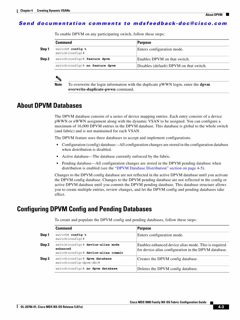
Send documenta t ion comments to mdsfeedback -doc@c i sco .com
Chapter 4 Creating Dynamic VSANsAbout DPVM
To enable DPVM on any participating switch, follow these steps:
Note To overwrite the login information with the duplicate pWWN login, enter the dpvm overwrite-duplicate-pwwn command.
About DPVM DatabasesThe DPVM database consists of a series of device mapping entries. Each entry consists of a device pWWN or nWWN assignment along with the dynamic VSAN to be assigned. You can configure a maximum of 16,000 DPVM entries in the DPVM database. This database is global to the whole switch (and fabric) and is not maintained for each VSAN.
The DPVM feature uses three databases to accept and implement configurations.
• Configuration (config) database—All configuration changes are stored in the configuration database when distribution is disabled.
• Active database—The database currently enforced by the fabric.
• Pending database—All configuration changes are stored in the DPVM pending database when distribution is enabled (see the “DPVM Database Distribution” section on page 4-5).
Changes to the DPVM config database are not reflected in the active DPVM database until you activate the DPVM config database. Changes to the DPVM pending database are not reflected in the config or active DPVM database until you commit the DPVM pending database. This database structure allows you to create multiple entries, review changes, and let the DPVM config and pending databases take effect.
Configuring DPVM Config and Pending DatabasesTo create and populate the DPVM config and pending databases, follow these steps:
Command Purpose
Step 1 switch# config tswitch(config)#
Enters configuration mode.
Step 2 switch(config)# feature dpvm Enables DPVM on that switch.
switch(config)# no feature dpvm Disables (default) DPVM on that switch.
Command Purpose
Step 1 switch# config tswitch(config)#
Enters configuration mode.
Step 2 switch(config)# device-alias mode enhancedswitch(config)# device-alias commit
Enables enhanced device alias mode. This is required for device-alias configuration in the DPVM database.
Step 3 switch(config)# dpvm databaseswitch(config-dpvm-db)#
Creates the DPVM config database.
switch(config)# no dpvm database Deletes the DPVM config database.
4-3Cisco MDS 9000 Family NX-OS Fabric Configuration Guide
OL-20706-01, Cisco MDS NX-OS Release 5.0(1a)
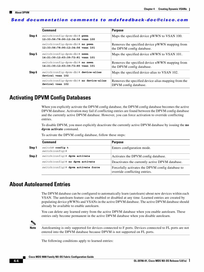
Send documenta t ion comments to mdsfeedback -doc@c i sco .com
Chapter 4 Creating Dynamic VSANsAbout DPVM
Activating DPVM Config DatabasesWhen you explicitly activate the DPVM config database, the DPVM config database becomes the active DPVM database. Activation may fail if conflicting entries are found between the DPVM config database and the currently active DPVM database. However, you can force activation to override conflicting entries.
To disable DPVM, you must explicitly deactivate the currently active DPVM database by issuing the no dpvm activate command.
To activate the DPVM config database, follow these steps:
About Autolearned EntriesThe DPVM database can be configured to automatically learn (autolearn) about new devices within each VSAN. The autolearn feature can be enabled or disabled at any time. Learned entries are created by populating device pWWNs and VSANs in the active DPVM database. The active DPVM database should already be available to enable autolearn.
You can delete any learned entry from the active DPVM database when you enable autolearn. These entries only become permanent in the active DPVM database when you disable autolearn.
Note Autolearning is only supported for devices connected to F ports. Devices connected to FL ports are not entered into the DPVM database because DPVM is not supported on FL ports.
The following conditions apply to learned entries:
Step 4 switch(config-dpvm-db)# pwwn 12:33:56:78:90:12:34:56 vsan 100
Maps the specified device pWWN to VSAN 100.
switch(config-dpvm-db)# no pwwn 12:33:56:78:90:12:34:56 vsan 101
Removes the specified device pWWN mapping from the DPVM config database.
Step 5 switch(config-dpvm-db)# nwwn 14:21:30:12:63:39:72:81 vsan 101
Maps the specified device nWWN to VSAN 101.
switch(config-dpvm-db)# no nwwn 14:21:30:12:63:39:72:80 vsan 101
Removes the specified device nWWN mapping from the DPVM config database.
Step 6 switch(config-dpvm-db)# device-alias device1 vsan 102
Maps the specified device-alias to VSAN 102.
switch(config-dpvm-db)# no device-alias device1 vsan 102
Removes the specified device-alias mapping from the DPVM config database.
Command Purpose
Command Purpose
Step 1 switch# config tswitch(config)#
Enters configuration mode.
Step 2 switch(config)# dpvm activate Activates the DPVM config database.
switch(config)# no dpvm activate Deactivates the currently active DPVM database.
switch(config)# dpvm activate force Forcefully activates the DPVM config database to override conflicting entries.
4-4Cisco MDS 9000 Family NX-OS Fabric Configuration Guide
OL-20706-01, Cisco MDS NX-OS Release 5.0(1a)

Send documenta t ion comments to mdsfeedback -doc@c i sco .com
Chapter 4 Creating Dynamic VSANsDPVM Database Distribution
• If a device logs out while autolearn is enabled, that entry is automatically deleted from the active DPVM database.
• If the same device logs multiple times into the switch through different ports, then the VSAN corresponding to last login is remembered.
• Learned entries do not override previously configured and activated entries.
• Learning is a two-part process—Enabling autolearning followed by disabling autolearning. When the auto-learn option is enabled, the following applies:
– Learning currently logged-in devices—Occurs from the time learning is enabled.
– Learning new device logins— Occurs as and when new devices log in to the switch.
Enabling AutolearningTo enable autolearning, follow these steps:
Clearing Learned EntriesYou can clear DPVM entries from the active DPVM database (if autolearn is still enabled) using one of two methods.
• To clear a single autolearn entry, use the clear dpvm auto-learn pwwn command.
switch# clear dpvm auto-learn pwwn 55:22:33:44:55:66:77:88
• To clear all autolearn entries, use the clear dpvm auto-learn command.
switch# clear dpvm auto-learn
Note These two commands do not start a session and can only be issued in the local switch.
DPVM Database DistributionIf the DPVM database is available on all switches in the fabric, devices can be moved anywhere and offer the greatest flexibility. To enable database distribution to the neighboring switches, the database should be consistently administered and distributed across all switches in the fabric. The Cisco NX-OS software uses the Cisco Fabric Services (CFS) infrastructure to achieve this requirement (refer to the Cisco MDS 9000 Family NX-OS System Management Configuration Guide).
This section describes how to distribute the DPVM database and includes the following topics:
Command Purpose
Step 1 switch# config tswitch(config)#
Enters configuration mode.
Step 2 switch(config)# dpvm auto-learn Enables learning on this switch.
switch(config)# no dpvm auto-learn Disables (default) learning on this switch.
switch(config)# clear dpvm auto-learn Clears the list of auto-learned entries.
switch(config)# clear dpvm auto-learn pwwn pwwn
Clears the list of auto-learned pWWN entries in the distributed DPVM database.
4-5Cisco MDS 9000 Family NX-OS Fabric Configuration Guide
OL-20706-01, Cisco MDS NX-OS Release 5.0(1a)

Send documenta t ion comments to mdsfeedback -doc@c i sco .com
Chapter 4 Creating Dynamic VSANsDPVM Database Distribution
• About DPVM Database Distribution, page 4-6
• Disabling DPVM Database Distribution, page 4-6
• About Locking the Fabric, page 4-6
• Locking the Fabric, page 4-7
• Committing Changes, page 4-7
• Discarding Changes, page 4-8
• Clearing a Locked Session, page 4-8
About DPVM Database DistributionUsing the CFS infrastructure, each DPVM server learns the DPVM database from each of its neighboring switches during the ISL bring-up process. If you change the database locally, the DPVM server notifies its neighboring switches, and that database is updated by all switches in the fabric.
If fabric distribution is enabled, all changes to the configuration database are stored in the DPVM pending database. These changes include the following tasks:
• Adding, deleting, or modifying database entries.
• Activating, deactivating, or deleting the configuration database.
• Enabling or disabling autolearning.
These changes are distributed to all switches in a fabric when you commit the changes. You can also discard (abort) the changes at this point.
Tip You can view the contents of the DPVM pending database by issuing the show dpvm pending command.
Disabling DPVM Database DistributionTo disable DPVM database distribution to the neighboring switches, follow these steps:
About Locking the FabricThe first action that modifies the existing configuration creates the DPVM pending database and locks the feature in the fabric. Once you lock the fabric, the following conditions apply:
• No other user can make any configuration changes to this feature.
Command Purpose
Step 1 switch# config tswitch(config)#
Enters configuration mode.
Step 2 switch(config)# no dpvm distribute Disables DPVM distribution to the neighboring switches.
switch(config)# dpvm distribute Enables (default) DPVM distribution to the neighboring switches.
4-6Cisco MDS 9000 Family NX-OS Fabric Configuration Guide
OL-20706-01, Cisco MDS NX-OS Release 5.0(1a)

Send documenta t ion comments to mdsfeedback -doc@c i sco .com
Chapter 4 Creating Dynamic VSANsDPVM Database Distribution
• A copy of the configuration database becomes the DPVM pending database. Modifications from this point on are made to the DPVM pending database. The DPVM pending database remains in effect until you commit the modifications to the DPVM pending database or discard (abort) the changes to the DPVM pending database.
Locking the FabricTo lock the fabric and apply changes to the DPVM pending database, follow these steps:
Committing ChangesIf you commit the changes made to the configuration, the configuration in the DPVM pending database are distributed to other switches. On a successful commit, the configuration change is applied throughout the fabric and the lock is released.
To commit the DPVM pending database, follow these steps:
Command Purpose
Step 1 switch# config tswitch(config)#
Enters configuration mode.
Step 2 switch(config)# dpvm databaseswitch(config-dpvm-db)#
Accesses the DPVM config database.
Step 3 switch(config-dpvm-db)# pwwn 11:22:33:44:55:66:77:88 vsan 11
Adds one entry to the DPVM config database.
Step 4 switch(config-dpvm-db)# exitswitch(config)#
Exits to configuration mode.
Step 5 switch(config)# dpvm activate Activates the DPVM config database.
Command Purpose
Step 1 switch# config tswitch(config)#
Enters configuration mode.
Step 2 switch(config)# dpvm commit Commits the database entries that are currently in the DPVM pending database.
4-7Cisco MDS 9000 Family NX-OS Fabric Configuration Guide
OL-20706-01, Cisco MDS NX-OS Release 5.0(1a)

Send documenta t ion comments to mdsfeedback -doc@c i sco .com
Chapter 4 Creating Dynamic VSANsDatabase Merge Guidelines
Discarding ChangesIf you discard (abort) the changes made to the DPVM pending database, the configurations remain unaffected and the lock is released.
To discard the DPVM pending database, follow these steps:
Clearing a Locked SessionIf you have performed a DPVM task and have forgotten to release the lock by either committing or discarding the changes, an administrator can release the lock from any switch in the fabric. If the administrator performs this task, your changes to the DPVM pending database are discarded and the fabric lock is released.
Tip The DPVM pending database is only available in the volatile directory and is subject to being discarded if the switch is restarted.
To use administrative privileges and release a locked DPVM session, use the clear dpvm session command in EXEC mode.
switch# clear dpvm session
Database Merge GuidelinesA database merge refers to a union of the configuration database and static (unlearned) entries in the active DPVM database. For information about CFS merge support, refer to the Cisco MDS 9000 Family NX-OS System Management Configuration Guide for detailed concepts.
When merging the DPVM database between two fabrics, follow these guidelines:
• Verify that the activation status and the auto-learn status is the same is both fabrics.
• Verify that the combined number of device entries in each database does not exceed 16 K.
Caution If you do not follow these two conditions, the merge will fail. The next distribution will forcefully synchronize the databases and the activation states in the fabric.
This section describes how to merge DPVM databases and includes the following topics:
• About Copying DPVM Databases, page 4-9
• Copying DPVM Databases, page 4-9
• Comparing Database Differences, page 4-9
• Displaying DPVM Merge Status and Statistics, page 4-10
Command Purpose
Step 1 switch# config tswitch(config)#
Enters configuration mode.
Step 2 switch(config)# dpvm abort Discards the database entries that are currently in the DPVM pending database.
4-8Cisco MDS 9000 Family NX-OS Fabric Configuration Guide
OL-20706-01, Cisco MDS NX-OS Release 5.0(1a)

Send documenta t ion comments to mdsfeedback -doc@c i sco .com
Chapter 4 Creating Dynamic VSANsDatabase Merge Guidelines
About Copying DPVM DatabasesThe following circumstances may require the active DPVM database to be copied to the DPVM config database:
• If the learned entries are only added to the active DPVM database.
• If the DPVM config database or entries in the DPVM config database are accidently deleted.
Note If you copy the DPVM database and fabric distribution is enabled, you must commit the changes.
Copying DPVM DatabasesTo copy the currently active DPVM database to the DPVM config database, use the dpvm database copy command.
switch# dpvm database copy activeLegend: “+” New Entry, “-” Missing Entry, “*” Possible Conflict Entry---------------------------------------------------------------------- pwwn 12:33:56:78:90:12:34:56 vsan 100- nwwn 14:21:30:12:63:39:72:81 vsan 101
Comparing Database DifferencesYou can compare the DPVM databases as follows:
• Use the dpvm database diff active command to compare the active DPVM database with the DPVM config database.
switch# dpvm database diff activeLegend: “+” New Entry, “-” Missing Entry, “*” Possible Conflict Entry---------------------------------------------------------------------- pwwn 44:22:33:44:55:66:77:88 vsan 44* pwwn 11:22:33:44:55:66:77:88 vsan 11
• Use the dpvm database diff config command to compare the DPVM config database with the active DPVM database.
switch# dpvm database diff configLegend: “+” New Entry, “-” Missing Entry, “*” Possible Conflict Entry---------------------------------------------------------------------+ pwwn 44:22:33:44:55:66:77:88 vsan 44* pwwn 11:22:33:44:55:66:77:88 vsan 22
• Use the show dpvm pending-diff command (when CFS distribution is enabled) to compare the DPVM pending database with the DPVM config database.
To add pending database entries to the DPVM config database, follow these steps:
Command Purpose
Step 1 switch# config tswitch(config)#
Enters configuration mode.
Step 2 switch(config)# dpvm distribute Enables CFS distribution.
4-9Cisco MDS 9000 Family NX-OS Fabric Configuration Guide
OL-20706-01, Cisco MDS NX-OS Release 5.0(1a)

Send documenta t ion comments to mdsfeedback -doc@c i sco .com
Chapter 4 Creating Dynamic VSANsDisplaying DPVM Configurations
Displaying DPVM Merge Status and StatisticsTo display the DPVM databases merge statistics, follow these steps:
This example shows the conflicts in DPVM databases merge:
switch# show dpvm merge statusLast Merge Time Stamp : Fri Aug 8 15:46:36 2008Last Merge State : FailLast Merge Result : FailLast Merge Failure Reason : DPVM DB conflict found during merge [cfs_status: 76] Last Merge Failure Details: DPVM merge failed due to database conflictLocal Switch WWN : 20:00:00:0d:ec:24:e5:00Remote Switch WWN : 20:00:00:0d:ec:09:d5:c0 -------------------------------------------------------------------------- Conflicting DPVM member(s) Loc VSAN Rem VSAN--------------------------------------------------------------------------dev-alias dpvm_dev_alias_1 [21:00:00:04:cf:cf:45:ba] 1313 1414dev-alias dpvm_dev_alias_2 [21:00:00:04:cf:cf:45:bb] 1313 1414dev-alias dpvm_dev_alias_3 [21:00:00:04:cf:cf:45:bc] 1313 1414[Total 3 conflict(s)]rbadri-excal13#
This example shows the conflicts in DDAS mode:
switch# show dpvm merge statusLast Merge Time Stamp : Fri Aug 8 15:46:36 2008Last Merge State : FailLast Merge Result : FailLast Merge Failure Reason : DPVM DB conflict found during merge [cfs_status: 76] Last Merge Failure Details: DPVM merge failed due to DDAS mode conflictLocal Switch WWN : 20:00:00:0d:ec:24:e5:00Remote Switch WWN : 20:00:00:0d:ec:09:d5:c0Local DDAS mode : BasicRemote DDAS mode : Enhanced
Displaying DPVM ConfigurationsUse the show dpvm command to display information about WWNs configured on a per VSAN basis (see Examples 4-1 to 4-6).
Step 3 switch(config)# dpvm database Accesses the DPVM config database.
Step 4 switch(config-dpvm-db)# pwwn 44:22:33:44:55:66:77:88 vsan 55switch(config-dpvm-db)# pwwn 55:22:33:44:55:66:77:88 vsan 55
Adds two entries to the DPVM config database.
Command Purpose
Command Purpose
switch# show dpvm merge statisticsswitch(config)#
Displays the DPVM databases merge statistics.
switch(config)# clear dpvm merge statisticsswitch(config)#
Clears the DPVM databases merge statistics.
4-10Cisco MDS 9000 Family NX-OS Fabric Configuration Guide
OL-20706-01, Cisco MDS NX-OS Release 5.0(1a)

Send documenta t ion comments to mdsfeedback -doc@c i sco .com
Chapter 4 Creating Dynamic VSANsSample DPVM Configuration
Example 4-1 Displays the DPVM Configuration Status
switch# show dpvm statusDB is activated successfully, auto-learn is on
Example 4-2 Displays the DPVM Current Dynamic Ports for the Specified VSAN
switch# show dpvm ports vsan 10--------------------------------------------------------------Interface Vsan Device pWWN Device nWWN--------------------------------------------------------------fc1/2 10 29:a0:00:05:30:00:6b:a0 fe:65:00:05:30:00:2b:a0
Example 4-3 Displays the DPVM Config Database
switch# show dpvm databasepwwn 11:22:33:44:55:66:77:88 vsan 11pwwn 22:22:33:44:55:66:77:88 vsan 22pwwn 33:22:33:44:55:66:77:88 vsan 33pwwn 44:22:33:44:55:66:77:88 vsan 44[Total 4 entries]
Example 4-4 Displays the DPVM Database
switch# show dpvm database activepwwn 11:22:33:44:55:66:77:88 vsan 22pwwn 22:22:33:44:55:66:77:88 vsan 22pwwn 33:22:33:44:55:66:77:88 vsan 33[Total 3 entries]* is auto-learnt entry
Example 4-5 Displays DPVM Config Database
switch# show dpvm databasepwwn 11:22:33:44:55:66:77:88 vsan 11pwwn 22:22:33:44:55:66:77:88 vsan 22pwwn 33:22:33:44:55:66:77:88 vsan 33pwwn 44:22:33:44:55:66:77:88 vsan 44[Total 4 entries]
Example 4-6 Compares Pending Database with the DPVM Config Database
switch# show dpvm pending-diffLegend: “+” New Entry, “-” Missing Entry, “*” Possible Conflict Entry---------------------------------------------------------------------+ pwwn 55:22:33:44:55:66:77:88 vsan 55- pwwn 11:22:33:44:55:66:77:88 vsan 11* pwwn 44:22:33:44:55:66:77:88 vsan 44
Sample DPVM ConfigurationTo configure a basic DPVM scenario, follow these steps:
Step 1 Enable DPVM and enable DPVM distribution.
switch1# config Enter configuration commands, one per line. End with CNTL/Z.
4-11Cisco MDS 9000 Family NX-OS Fabric Configuration Guide
OL-20706-01, Cisco MDS NX-OS Release 5.0(1a)
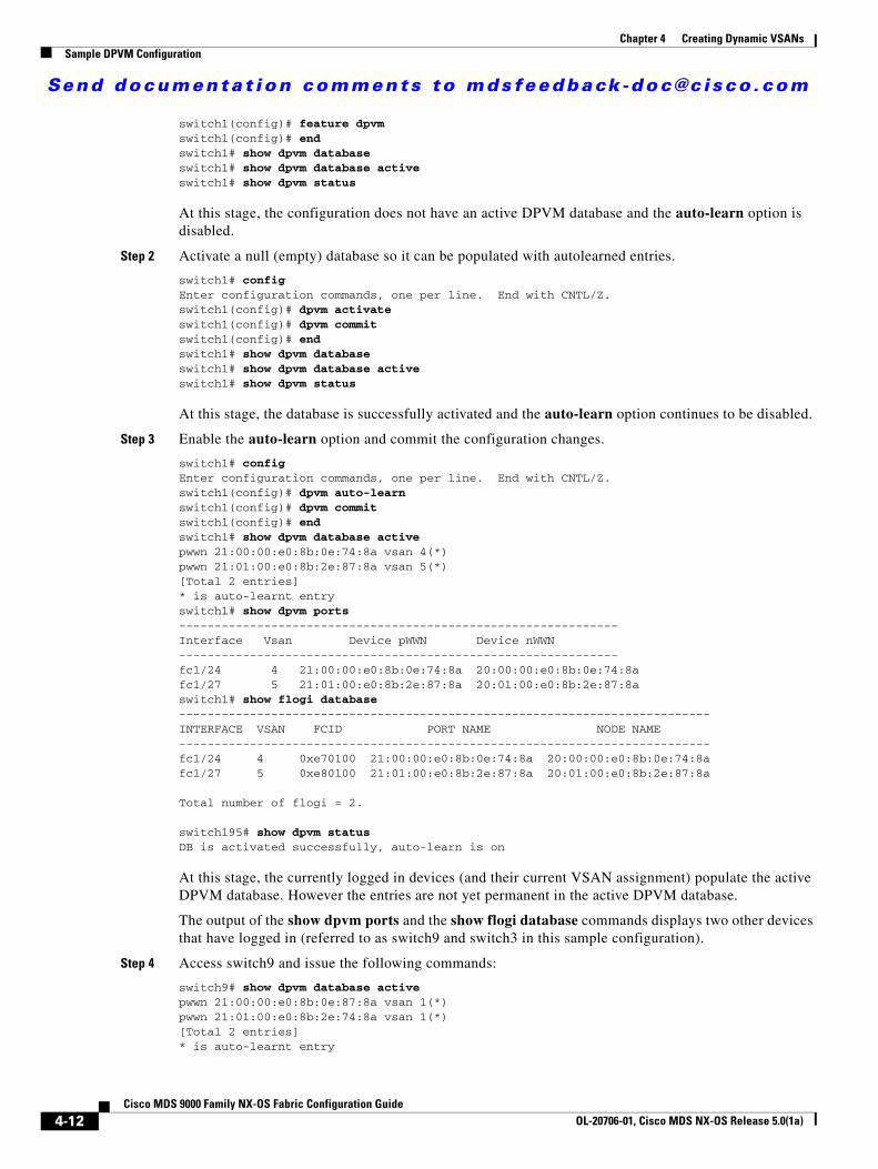
Send documenta t ion comments to mdsfeedback -doc@c i sco .com
Chapter 4 Creating Dynamic VSANsSample DPVM Configuration
switch1(config)# feature dpvmswitch1(config)# end switch1# show dpvm database switch1# show dpvm database active switch1# show dpvm status
At this stage, the configuration does not have an active DPVM database and the auto-learn option is disabled.
Step 2 Activate a null (empty) database so it can be populated with autolearned entries.
switch1# config Enter configuration commands, one per line. End with CNTL/Z. switch1(config)# dpvm activate switch1(config)# dpvm commit switch1(config)# end switch1# show dpvm database switch1# show dpvm database active switch1# show dpvm status
At this stage, the database is successfully activated and the auto-learn option continues to be disabled.
Step 3 Enable the auto-learn option and commit the configuration changes.
switch1# config Enter configuration commands, one per line. End with CNTL/Z. switch1(config)# dpvm auto-learn switch1(config)# dpvm commit switch1(config)# end switch1# show dpvm database active pwwn 21:00:00:e0:8b:0e:74:8a vsan 4(*) pwwn 21:01:00:e0:8b:2e:87:8a vsan 5(*) [Total 2 entries] * is auto-learnt entry switch1# show dpvm ports -------------------------------------------------------------- Interface Vsan Device pWWN Device nWWN -------------------------------------------------------------- fc1/24 4 21:00:00:e0:8b:0e:74:8a 20:00:00:e0:8b:0e:74:8a fc1/27 5 21:01:00:e0:8b:2e:87:8a 20:01:00:e0:8b:2e:87:8a switch1# show flogi database --------------------------------------------------------------------------- INTERFACE VSAN FCID PORT NAME NODE NAME --------------------------------------------------------------------------- fc1/24 4 0xe70100 21:00:00:e0:8b:0e:74:8a 20:00:00:e0:8b:0e:74:8a fc1/27 5 0xe80100 21:01:00:e0:8b:2e:87:8a 20:01:00:e0:8b:2e:87:8a
Total number of flogi = 2.
switch195# show dpvm status DB is activated successfully, auto-learn is on
At this stage, the currently logged in devices (and their current VSAN assignment) populate the active DPVM database. However the entries are not yet permanent in the active DPVM database.
The output of the show dpvm ports and the show flogi database commands displays two other devices that have logged in (referred to as switch9 and switch3 in this sample configuration).
Step 4 Access switch9 and issue the following commands:
switch9# show dpvm database active pwwn 21:00:00:e0:8b:0e:87:8a vsan 1(*) pwwn 21:01:00:e0:8b:2e:74:8a vsan 1(*) [Total 2 entries] * is auto-learnt entry
4-12Cisco MDS 9000 Family NX-OS Fabric Configuration Guide
OL-20706-01, Cisco MDS NX-OS Release 5.0(1a)

Send documenta t ion comments to mdsfeedback -doc@c i sco .com
Chapter 4 Creating Dynamic VSANsSample DPVM Configuration
switch9# show dpvm status DB is activated successfully, auto-learn is on
Step 5 Access switch3 and issue the following commands:
switch3# show dpvm database active pwwn 21:00:00:e0:8b:0e:76:8a vsan 1(*) pwwn 21:01:00:e0:8b:2e:76:8a vsan 1(*) [Total 2 entries] * is auto-learnt entry switch3# show dpvm status DB is activated successfully, auto-learn is on
Step 6 Disable autolearning in switch1 and commit the configuration changes.
switch1# config Enter configuration commands, one per line. End with CNTL/Z. switch1(config)# no dpvm auto-learn switch1(config)# dpvm commit switch1(config)# end switch1# show dpvm status DB is activated successfully, auto-learn is off switch1# show dpvm database active pwwn 21:00:00:e0:8b:0e:74:8a vsan 4 pwwn 21:01:00:e0:8b:2e:87:8a vsan 5 pwwn 21:00:00:e0:8b:0e:87:8a vsan 1 pwwn 21:01:00:e0:8b:2e:74:8a vsan 1 pwwn 21:00:00:e0:8b:0e:76:8a vsan 1 pwwn 21:01:00:e0:8b:2e:76:8a vsan 1 [Total 6 entries] * is auto-learnt entry switch1# show dpvm status DB is activated successfully, auto-learn is off
At this stage, the autolearned entries are made permanent in the active DPVM database.
Step 7 Access switch9 and issue the following commands:
switch9# show dpvm database active pwwn 21:00:00:e0:8b:0e:87:8a vsan 1 pwwn 21:01:00:e0:8b:2e:74:8a vsan 1 pwwn 21:00:00:e0:8b:0e:76:8a vsan 1 pwwn 21:01:00:e0:8b:2e:76:8a vsan 1 pwwn 21:00:00:e0:8b:0e:74:8a vsan 4 pwwn 21:01:00:e0:8b:2e:87:8a vsan 5 [Total 6 entries] * is auto-learnt entry switch9# show dpvm status DB is activated successfully, auto-learn is off
Step 8 Access switch3 and issue the following commands:
switch3# show dpvm database active pwwn 21:00:00:e0:8b:0e:76:8a vsan 1 pwwn 21:01:00:e0:8b:2e:76:8a vsan 1 pwwn 21:00:00:e0:8b:0e:87:8a vsan 1 pwwn 21:01:00:e0:8b:2e:74:8a vsan 1 pwwn 21:00:00:e0:8b:0e:74:8a vsan 4 pwwn 21:01:00:e0:8b:2e:87:8a vsan 5 [Total 6 entries] * is auto-learnt entry switch3# show dpvm status
4-13Cisco MDS 9000 Family NX-OS Fabric Configuration Guide
OL-20706-01, Cisco MDS NX-OS Release 5.0(1a)

Send documenta t ion comments to mdsfeedback -doc@c i sco .com
Chapter 4 Creating Dynamic VSANsDefault Settings
DB is activated successfully, auto-learn is off
Note These basic steps help you determine that the information is identical in all the switches in the fabric.
You have now configured a basic DPVM scenario in a Cisco MDS 9000 Family switch.
Default SettingsTable 4-1 lists the default settings for DPVM parameters.
Table 4-1 Default DPVM Parameters
Parameters Default
DPVM Disabled.
DPVM distribution Enabled.
Autolearning Disabled.
4-14Cisco MDS 9000 Family NX-OS Fabric Configuration Guide
OL-20706-01, Cisco MDS NX-OS Release 5.0(1a)

Send documenta t ion comments to mdsfeedback -doc@c i sco .com
Cisco MOL-20706-01, Cisco MDS NX-OS Release 5.0(1a)
C H A P T E R 5
Configuring and Managing ZonesZoning enables you to set up access control between storage devices or user groups. If you have administrator privileges in your fabric, you can create zones to increase network security and to prevent data loss or corruption. Zoning is enforced by examining the source-destination ID field.
Advanced zoning capabilities specified in the FC-GS-4 and FC-SW-3 standards are provided. You can use either the existing basic zoning capabilities or the advanced, standards-compliant zoning capabilities.
This chapter includes the following sections:
• About Zoning, page 5-1
• Zone Configuration, page 5-6
• Zone Sets, page 5-7
• Zone Set Distribution, page 5-14
• Zone Set Duplication, page 5-16
• Advanced Zone Attributes, page 5-19
• Displaying Zone Information, page 5-25
• Enhanced Zoning, page 5-31
• Compacting the Zone Database for Downgrading, page 5-41
• Zone and Zone Set Analysis, page 5-42
• Default Settings, page 5-43
Note Table 2-1 on page 2-4 lists the differences between zones and VSANs.
About ZoningZoning has the following features:
• A zone consists of multiple zone members.
– Members in a zone can access each other; members in different zones cannot access each other.
– If zoning is not activated, all devices are members of the default zone.
– If zoning is activated, any device that is not in an active zone (a zone that is part of an active zone set) is a member of the default zone.
5-1DS 9000 Family NX-OS Fabric Configuration Guide

Send documenta t ion comments to mdsfeedback -doc@c i sco .com
Chapter 5 Configuring and Managing ZonesAbout Zoning
– Zones can vary in size.
– Devices can belong to more than one zone.
– A physical fabric can have a maximum of 16,000 members. This includes all VSANs in the fabric.
• A zone set consists of one or more zones.
– A zone set can be activated or deactivated as a single entity across all switches in the fabric.
– Only one zone set can be activated at any time.
– A zone can be a member of more than one zone set.
– A zone switch can have a maximum of 500 zone sets.
• Zoning can be administered from any switch in the fabric.
– When you activate a zone (from any switch), all switches in the fabric receive the active zone set. Additionally, full zone sets are distributed to all switches in the fabric, if this feature is enabled in the source switch.
– If a new switch is added to an existing fabric, zone sets are acquired by the new switch.
• Zone changes can be configured nondisruptively. New zones and zone sets can be activated without interrupting traffic on unaffected ports or devices.
• Zone membership criteria is based mainly on WWNs or FC IDs.
– Port world wide name (pWWN)—Specifies the pWWN of an N port attached to the switch as a member of the zone.
– Fabric pWWN—Specifies the WWN of the fabric port (switch port’s WWN). This membership is also referred to as port-based zoning.
– FC ID—Specifies the FC ID of an N port attached to the switch as a member of the zone.
– Interface and switch WWN (sWWN)—Specifies the interface of a switch identified by the sWWN. This membership is also referred to as interface-based zoning.
– Interface and domain ID—Specifies the interface of a switch identified by the domain ID.
– Domain ID and port number—Specifies the domain ID of an MDS domain and additionally specifies a port belonging to a non-Cisco switch.
– IPv4 address—Specifies the IPv4 address (and optionally the subnet mask) of an attached device.
– IPv6 address—The IPv6 address of an attached device in 128 bits in colon(:)-separated hexadecimal format.
• Default zone membership includes all ports or WWNs that do not have a specific membership association. Access between default zone members is controlled by the default zone policy.
• You can configure up to 8000 zones per VSAN and a maximum of 8000 zones for all VSANs on the switch.
Zoning ExampleFigure 5-1 illustrates a zone set with two zones, zone 1 and zone 2, in a fabric. Zone 1 provides access from all three hosts (H1, H2, H3) to the data residing on storage systems S1 and S2. Zone 2 restricts the data on S3 to access only by H3. Note that H3 resides in both zones.
5-2Cisco MDS 9000 Family NX-OS Fabric Configuration Guide
OL-20706-01, Cisco MDS NX-OS Release 5.0(1a)
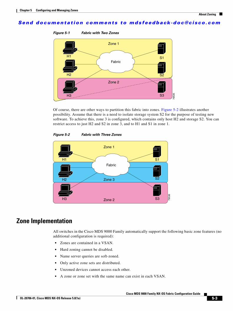
Send documenta t ion comments to mdsfeedback -doc@c i sco .com
Chapter 5 Configuring and Managing ZonesAbout Zoning
Figure 5-1 Fabric with Two Zones
Of course, there are other ways to partition this fabric into zones. Figure 5-2 illustrates another possibility. Assume that there is a need to isolate storage system S2 for the purpose of testing new software. To achieve this, zone 3 is configured, which contains only host H2 and storage S2. You can restrict access to just H2 and S2 in zone 3, and to H1 and S1 in zone 1.
Figure 5-2 Fabric with Three Zones
Zone ImplementationAll switches in the Cisco MDS 9000 Family automatically support the following basic zone features (no additional configuration is required):
• Zones are contained in a VSAN.
• Hard zoning cannot be disabled.
• Name server queries are soft-zoned.
• Only active zone sets are distributed.
• Unzoned devices cannot access each other.
• A zone or zone set with the same name can exist in each VSAN.
H1 S1
S2
S3
H2
H3
Zone 1
Zone 2
7953
5
Fabric
H1 S1
S2
S3
H2
H3
Zone 1
Zone 2
Zone 3
7953
6
Fabric
5-3Cisco MDS 9000 Family NX-OS Fabric Configuration Guide
OL-20706-01, Cisco MDS NX-OS Release 5.0(1a)

Send documenta t ion comments to mdsfeedback -doc@c i sco .com
Chapter 5 Configuring and Managing ZonesAbout Zoning
• Each VSAN has a full database and an active database.
• Active zone sets cannot be changed, without activating a full zone database.
• Active zone sets are preserved across switch reboots.
• Changes to the full database must be explicitly saved.
• Zone reactivation (a zone set is active and you activate another zone set) does not disrupt existing traffic.
If required, you can additionally configure the following zone features:
• Propagate full zone sets to all switches on a per VSAN basis.
• Change the default policy for unzoned members.
• Interoperate with other vendors by configuring a VSAN in the interop mode. You can also configure one VSAN in the interop mode and another VSAN in the basic mode in the same switch without disrupting each other.
• Bring E ports out of isolation.
Zone Member Configuration GuidelinesAll members of a zone can communicate with each other. For a zone with N members, N*(N-1) access permissions need to be enabled. The best practice is to avoid configuring large numbers of targets or large numbers of initiators in a single zone. This type of configuration wastes switch resources by provisioning and managing many communicating pairs (initiator-to-initiator or target-to-target) that will never actually communicate with each other. For this reason, a single initiator with a single target is the most efficient approach to zoning.
The following guidelines must be considered when creating zone members:
• Configuring only one initiator and one target for a zone provides the most efficient use of the switch resources.
• Configuring the same initiator to multiple targets is accepted.
• Configuring multiple initiators to multiple targets is not recommended.
Active and Full Zone Set ConsiderationsBefore configuring a zone set, consider the following guidelines:
• Each VSAN can have multiple zone sets but only one zone set can be active at any given time.
• When you create a zone set, that zone set becomes a part of the full zone set.
• When you activate a zone set, a copy of the zone set from the full zone set is used to enforce zoning, and is called the active zone set. An active zone set cannot be modified. A zone that is part of an active zone set is called an active zone.
• The administrator can modify the full zone set even if a zone set with the same name is active. However, the modification will be enforced only upon reactivation.
• When the activation is done, the active zone set is automatically stored in persistent configuration. This enables the switch to preserve the active zone set information across switch resets.
• All other switches in the fabric receive the active zone set so they can enforce zoning in their respective switches.
5-4Cisco MDS 9000 Family NX-OS Fabric Configuration Guide
OL-20706-01, Cisco MDS NX-OS Release 5.0(1a)

Send documenta t ion comments to mdsfeedback -doc@c i sco .com
Chapter 5 Configuring and Managing ZonesAbout Zoning
• Hard and soft zoning are implemented using the active zone set. Modifications take effect during zone set activation.
• An FC ID or Nx port that is not part of the active zone set belongs to the default zone and the default zone information is not distributed to other switches.
Note If one zone set is active and you activate another zone set, the currently active zone set is automatically deactivated. You do not need to explicitly deactivate the currently active zone set before activating a new zone set.
Figure 5-3 shows a zone being added to an activated zone set.
5-5Cisco MDS 9000 Family NX-OS Fabric Configuration Guide
OL-20706-01, Cisco MDS NX-OS Release 5.0(1a)

Send documenta t ion comments to mdsfeedback -doc@c i sco .com
Chapter 5 Configuring and Managing ZonesZone Configuration
Figure 5-3 Active and Full Zone Sets
Zone ConfigurationThis section describes how to configure zones and includes the following topic(s):
• Configuring a Zone, page 5-7
Zone set Z1
Zone AZone BZone C
Zone set Z2
Zone CZone DZone E
Zone set Z3
Zone AZone CZone D
Zone set Z1
Zone AZone BZone C
Zone set Z2
Zone CZone DZone E
Zone set Z3
Zone AZone CZone D
Full zone set
Zone set Z1
Zone AZone BZone C
After activating Zone set Z1
Full zone set
Activezone set
Zone set Z1
Zone AZone BZone C
Zone set Z2
Zone CZone DZone E
Zone set Z3
Zone AZone CZone D
Zone set Z1
Zone AZone BZone C
After adding Zone D to Zone set Z1
Full zone set
Activezone set
Zone set Z1
Zone AZone BZone C
Zone set Z2
Zone CZone DZone E
Zone set Z3
Zone AZone CZone D
Zone set Z1
Zone AZone BZone C
After activating Zone set Z1 again
Full zone set
Activezone set
Zone D
Zone D
Zone D
No active Zone set
79
94
8
5-6Cisco MDS 9000 Family NX-OS Fabric Configuration Guide
OL-20706-01, Cisco MDS NX-OS Release 5.0(1a)

Send documenta t ion comments to mdsfeedback -doc@c i sco .com
Chapter 5 Configuring and Managing ZonesZone Sets
Configuring a ZoneTo configure a zone and assign a zone name, follow these steps:
Tip Use the show wwn switch command to retrieve the sWWN. If you do not provide a sWWN, the software automatically uses the local sWWN.
Note Interface-based zoning only works with Cisco MDS 9000 Family switches. Interface-based zoning does not work if interop mode is configured in that VSAN.
Zone SetsZones provide a mechanism for specifying access control, while zone sets are a grouping of zones to enforce access control in the fabric.
Command Purpose
Step 1 switch# config t Enters configuration mode.
Step 2 switch(config)# zone name Zone1 vsan 3switch(config-zone)#
Configures a zone called Zone1 for the VSAN called vsan3.
Note All alphanumeric characters or one of the following symbols ($, -, ^, _) are supported.
Step 3 switch(config-zone)# member type value pWWN example:switch(config-zone)# member pwwn 10:00:00:23:45:67:89:abFabric pWWN example:switch(config-zone)# member fwwn 10:01:10:01:10:ab:cd:ef FC ID example:switch(config-zone)# member fcid 0xce00d1 FC alias example:switch(config-zone)# member fcalias PayrollDomain ID example:switch(config-zone)# member domain-id 2 portnumber 23IPv4 address example:switch(config-zone)# member ip-address 10.15.0.0 255.255.0.0IPv6 address example:switch(config-zone)# member ipv6-address 2001::db8:800:200c:417a/64Local sWWN interface example:switch(config-zone)# member interface fc 2/1Remote sWWN interface example:switch(config-zone)# member interface fc2/1 swwn 20:00:00:05:30:00:4a:de Domain ID interface example:switch(config-zone)# member interface fc2/1 domain-id 25
Configures a member for the specified zone (Zone1) based on the type (pWWN, fabric pWWN, FC ID, fcalias, domain ID, IPv4 address, IPv6 address, or interface) and value specified.
Caution You must only configure pWWN-type zoning on all MDS switches running Cisco SAN-OS if there is a Cisco MDS 9020 switch running FabricWare in the same fabric.
Tip Use a relevant display command (for example, show interface or show flogi database) to obtain the required value in hex format.
5-7Cisco MDS 9000 Family NX-OS Fabric Configuration Guide
OL-20706-01, Cisco MDS NX-OS Release 5.0(1a)

Send documenta t ion comments to mdsfeedback -doc@c i sco .com
Chapter 5 Configuring and Managing ZonesZone Sets
This section describes zone sets and includes the following topics:
• Configuring the Default Zone Access Permission, page 5-11
• About FC Alias Creation, page 5-11
• Creating FC Aliases, page 5-11
• Creating Zone Sets and Adding Member Zones, page 5-12
• Zone Enforcement, page 5-14
About Zone SetsZones provide a mechanism for specifying access control, while zone sets are a grouping of zones to enforce access control in the fabric.
Zone sets are configured with the names of the member zones and the VSAN (if the zone set is in a configured VSAN).
Zone Set Distribution—You can distribute full zone sets using one of two methods: one-time distribution or full zone set distribution.
Zone Set Duplication—You can make a copy of a zone set and then edit it without altering the original zone set. You can copy an active zone set from the bootflash: directory, volatile: directory, or slot0, to one of the following areas:
• To the full zone set
• To a remote location (using FTP, SCP, SFTP, or TFTP)
The active zone set is not part of the full zone set. You cannot make changes to an existing zone set and activate it, if the full zone set is lost or is not propagated.
About Zone Set CreationIn Figure 5-4, two separate sets are created, each with its own membership hierarchy and zone members.
5-8Cisco MDS 9000 Family NX-OS Fabric Configuration Guide
OL-20706-01, Cisco MDS NX-OS Release 5.0(1a)

Send documenta t ion comments to mdsfeedback -doc@c i sco .com
Chapter 5 Configuring and Managing ZonesZone Sets
Figure 5-4 Hierarchy of Zone Sets, Zones, and Zone Members
Either zone set A or zone set B can be activated (but not together).
Tip Zone sets are configured with the names of the member zones and the VSAN (if the zone set is in a configured VSAN).
Zone 3H2, S2
Zone 2H3, S2
Zone 1H1, H3, S1
Zone set A Zone set B
H1 H2 H3 S1 S2 7953
7
5-9Cisco MDS 9000 Family NX-OS Fabric Configuration Guide
OL-20706-01, Cisco MDS NX-OS Release 5.0(1a)

Send documenta t ion comments to mdsfeedback -doc@c i sco .com
Chapter 5 Configuring and Managing ZonesZone Sets
Activating a Zone SetChanges to a zone set do not take effect in a full zone set until you activate it.
To activate or deactivate an existing zone set, follow these steps:
About the Default ZoneEach member of a fabric (in effect a device attached to an Nx port) can belong to any zone. If a member is not part of any active zone, it is considered to be part of the default zone. Therefore, if no zone set is active in the fabric, all devices are considered to be in the default zone. Even though a member can belong to multiple zones, a member that is part of the default zone cannot be part of any other zone. The switch determines whether a port is a member of the default zone when the attached port comes up.
Note Unlike configured zones, default zone information is not distributed to the other switches in the fabric.
Traffic can either be permitted or denied among members of the default zone. This information is not distributed to all switches; it must be configured in each switch.
Note When the switch is initialized for the first time, no zones are configured and all members are considered to be part of the default zone. Members are not permitted to talk to each other.
Configure the default zone policy on each switch in the fabric. If you change the default zone policy on one switch in a fabric, be sure to change it on all the other switches in the fabric.
Note The default settings for default zone configurations can be changed.
The default zone members are explicitly listed when the default policy is configured as permit or when a zone set is active. When the default policy is configured as deny, the members of this zone are not explicitly enumerated when you issue the show zoneset active command.
Note The current default zoning policy in both the switches are deny. In MDS9222i the active zoneset is "coco_isola_zoneset". In MDS 9513, there is no active zoneset, but because default zoning policy is deny, the hidden active zoneset is "d__efault__cfg". Thus zone merge is failing. The behavior is even same between two brocade switches.
Command Purpose
Step 1 switch# config tswitch(config)#
Enters configuration mode.
Step 2 switch(config)# zoneset activate name Zoneset1 vsan 3 Activates the specified zone set.
switch(config)# no zoneset activate name Zoneset1 vsan 3 Deactivates the specified zone set.
5-10Cisco MDS 9000 Family NX-OS Fabric Configuration Guide
OL-20706-01, Cisco MDS NX-OS Release 5.0(1a)

Send documenta t ion comments to mdsfeedback -doc@c i sco .com
Chapter 5 Configuring and Managing ZonesZone Sets
Configuring the Default Zone Access PermissionTo permit or deny traffic to members in the default zone, follow these steps:
About FC Alias CreationYou can assign an alias name and configure an alias member using the following values:
• pWWN—The WWN of the N or NL port is in hex format (for example, 10:00:00:23:45:67:89:ab).
• fWWN—The WWN of the fabric port name is in hex format (for example, 10:00:00:23:45:67:89:ab).
• FC ID—The N port ID is in 0xhhhhhh format (for example, 0xce00d1).
• Domain ID—The domain ID is an integer from 1 to 239. A mandatory port number of a non-Cisco switch is required to complete this membership configuration.
• IPv4 address—The IPv4 address of an attached device is in 32 bits in dotted decimal format along with an optional subnet mask. If a mask is specified, any device within the subnet becomes a member of the specified zone.
• IPv6 address—The IPv6 address of an attached device is in 128 bits in colon- (:) separated) hexadecimal format.
• Interface—Interface-based zoning is similar to port-based zoning because the switch interface is used to configure the zone. You can specify a switch interface as a zone member for both local and remote switches. To specify a remote switch, enter the remote switch WWN (sWWN) or the domain ID in the particular VSAN.
Tip The Cisco NX-OS software supports a maximum of 2048 aliases per VSAN.
Creating FC AliasesTo create an alias, follow these steps:
Command Purpose
Step 1 switch# config t Enters configuration mode.
Step 2 switch(config)# zone default-zone permit vsan 1 Permits traffic flow to default zone members.
switch(config)# no zone default-zone permit vsan 1 Denies (default) traffic flow to default zone members.
Command Purpose
Step 1 switch# config t Enters configuration mode.
Step 2 switch(config)# fcalias name AliasSample vsan 3switch(config-fcalias)#
Configures an alias name (AliasSample).
5-11Cisco MDS 9000 Family NX-OS Fabric Configuration Guide
OL-20706-01, Cisco MDS NX-OS Release 5.0(1a)

Send documenta t ion comments to mdsfeedback -doc@c i sco .com
Chapter 5 Configuring and Managing ZonesZone Sets
Creating Zone Sets and Adding Member ZonesTo create a zone set to include several zones, follow these steps:
Step 3 switch(config-fcalias)# member type value pWWN example:switch(config-fcalias)# member pwwn 10:00:00:23:45:67:89:abfWWN example:switch(config-fcalias)# member fwwn 10:01:10:01:10:ab:cd:ef FC ID example:switch(config-fcalias)# member fcid 0x222222 Domain ID example:switch(config-fcalias)# member domain-id 2 portnumber 23IPv4 address example:switch(config-fcalias)# member ip-address 10.15.0.0 255.255.0.0IPv6 address example:switch(config-fcalias)# member ipv6-address 2001::db8:800:200c:417a/64Local sWWN interface example:switch(config-fcalias)# member interface fc 2/1Remote sWWN interface example:switch(config-fcalias)# member interface fc2/1 swwn 20:00:00:05:30:00:4a:de Domain ID interface example:switch(config-fcalias)# member interface fc2/1 domain-id 25
Configures a member for the specified fcalias (AliasSample) based on the type (pWWN, fabric pWWN, FC ID, domain ID, IPv4 address, IPv6 address, or interface) and value specified.
Step 4 Note Multiple members can be specified on multiple lines.
Command Purpose
Command Purpose
Step 1 switch# config t Enters configuration mode.
Step 2 switch(config)# zoneset name Zoneset1 vsan 3switch(config-zoneset)#
Configures a zone set called Zoneset1.
Tip To activate a zone set, you must first create the zone and a zone set.
Step 3 switch(config-zoneset)# member Zone1 Adds Zone1 as a member of the specified zone set (Zoneset1).
Tip If the specified zone name was not previously configured, this command will return the Zone not present error message.
5-12Cisco MDS 9000 Family NX-OS Fabric Configuration Guide
OL-20706-01, Cisco MDS NX-OS Release 5.0(1a)

Send documenta t ion comments to mdsfeedback -doc@c i sco .com
Chapter 5 Configuring and Managing ZonesZone Sets
Tip You do not have to issue the copy running-config startup-config command to store the active zone set. However, you need to issue the copy running-config startup-config command to explicitly store full zone sets. It is not available across switch resets.
Caution If you deactivate the active zone set in a VSAN that is also configured for IVR, the active IVR zone set (IVZS) is also deactivated and all IVR traffic to and from the switch is stopped. This deactivation can disrupt traffic in more than one VSAN. Before deactivating the active zone set, check the active zone analysis for the VSAN (see the “Zone and Zone Set Analysis” section on page 5-42). To reactivate the IVZS, you must reactivate the regular zone set (refer to the Cisco MDS 9000 Family NX-OS Inter-VSAN Routing Configuration Guide).
Caution If the currently active zone set contains IVR zones, activating the zone set from a switch where IVR is not enabled disrupts IVR traffic to and from that VSAN. We strongly recommend that you always activate the zone set from an IVR-enabled switch to avoid disrupting IVR traffic.
Note Set the device alias mode to enhanced when using SDV (because the pWWN of a virtual device could change).
For example, SDV is enabled on a switch and a virtual device is defined. SDV assigns a pWWN for the virtual device, and it is zoned based on the pWWN in a zone. If you later disable SDV, this configuration is lost. If you reenable SDV and create the virtual device using the same name, there is no guarantee that it will get the same pWWN again. You will have to rezone the pWWN-based zone. However, if you perform zoning based on the device-alias name, there are no configuration changes required if or when the pWWN changes.
Be sure you understand how device alias modes work before enabling them. Refer to Chapter 6, “Distributing Device Alias Services” for details and requirements about device alias modes.
Step 4 switch(config-zoneset)# zone name InlineZone1 switch(config-zoneset-zone)#
Adds a zone (InlineZone1) to the specified zone set (Zoneset1).
Tip Execute this step only if you need to create a zone from a zone set prompt.
Step 5 switch(config-zoneset-zone)# member fcid 0x111112switch(config-zoneset-zone)#
Adds a new member (FC ID 0x111112) to the new zone (InlineZone1).
Tip Execute this step only if you need to add a member to a zone from a zone set prompt.
Command Purpose
5-13Cisco MDS 9000 Family NX-OS Fabric Configuration Guide
OL-20706-01, Cisco MDS NX-OS Release 5.0(1a)

Send documenta t ion comments to mdsfeedback -doc@c i sco .com
Chapter 5 Configuring and Managing ZonesZone Set Distribution
Zone EnforcementZoning can be enforced in two ways: soft and hard. Each end device (N port or NL port) discovers other devices in the fabric by querying the name server. When a device logs in to the name server, the name server returns the list of other devices that can be accessed by the querying device. If an Nx port does not know about the FC IDs of other devices outside its zone, it cannot access those devices.
In soft zoning, zoning restrictions are applied only during interaction between the name server and the end device. If an end device somehow knows the FC ID of a device outside its zone, it can access that device.
Hard zoning is enforced by the hardware on each frame sent by an Nx port. As frames enter the switch, source-destination IDs are compared with permitted combinations to allow the frame at wirespeed. Hard zoning is applied to all forms of zoning.
Note Hard zoning enforces zoning restrictions on every frame, and prevents unauthorized access.
Switches in the Cisco MDS 9000 Family support both hard and soft zoning.
Zone Set DistributionYou can distribute full zone sets using one of two methods: one-time distribution at the EXEC mode level or full zone set distributionat the configuration mode level.
Table 5-1 lists the differences between these distribution methods.
This section describes zone set distribution and includes the following topics:
• Enabling Full Zone Set Distribution, page 5-14
• Enabling a One-Time Distribution, page 5-15
• About Recovering from Link Isolation, page 5-15
• Importing and Exporting Zone Sets, page 5-16
Enabling Full Zone Set DistributionAll switches in the Cisco MDS 9000 Family distribute active zone sets when new E port links come up or when a new zone set is activated in a VSAN. The zone set distribution takes effect while sending merge requests to the adjacent switch or while activating a zone set.
Table 5-1 zoneset distribution Command Differences
zoneset distribute vsan Command (EXEC Mode)
zoneset distribute full vsan Command(Configuration Mode)
Distributes the full zone set immediately. Does not distribute the full zone set immediately.
Does not distribute the full zone set information along with the active zone set during activation, deactivation, or merge process.
Remembers to distribute the full zone set information along with the active zone set during activation, deactivation, and merge processes.
5-14Cisco MDS 9000 Family NX-OS Fabric Configuration Guide
OL-20706-01, Cisco MDS NX-OS Release 5.0(1a)

Send documenta t ion comments to mdsfeedback -doc@c i sco .com
Chapter 5 Configuring and Managing ZonesZone Set Distribution
To enable full zone set and active zone set distribution to all switches on a per VSAN basis, follow these steps:
Enabling a One-Time DistributionUse the zoneset distribute vsan vsan-id command in EXEC mode to perform this distribution.
switch# zoneset distribute vsan 2Zoneset distribution initiated. check zone status
This command only distributes the full zone set information; it does not save the information to the startup configuration. You must explicitly issue the copy running-config startup-config command to save the full zone set information to the startup configuration.
Note The zoneset distribute vsan vsan-id command is supported in interop 2 and interop 3 modes, not in interop 1 mode.
Use the show zone status vsan vsan-id command to check the status of the one-time zone set distribution request.
switch# show zone status vsan 2VSAN: 3 default-zone: permit distribute: active only Interop: 100
mode:basic merge-control:allow session:none hard-zoning:enabledDefault zone: qos:low broadcast:disabled ronly:disabledFull Zoning Database : Zonesets:0 Zones:0 Aliases: 0Active Zoning Database : Name: nozoneset Zonesets:1 Zones:2Status: Zoneset distribution completed at 04:01:06 Aug 28 2004
About Recovering from Link Isolation When two switches in a fabric are merged using a TE or E port, these TE and E ports may become isolated when the active zone set databases are different between the two switches or fabrics. When a TE port or an E port become isolated, you can recover that port from its isolated state using one of three options:
• Import the neighboring switch's active zone set database and replace the current active zone set (see Figure 5-5).
• Export the current database to the neighboring switch.
• Manually resolve the conflict by editing the full zone set, activating the corrected zone set, and then bringing up the link.
Command Purpose
Step 1 switch# config t Enters configuration mode.
Step 2 switch(config)# zoneset distribute full vsan 33 Enables sending a full zone set along with an active zone set.
5-15Cisco MDS 9000 Family NX-OS Fabric Configuration Guide
OL-20706-01, Cisco MDS NX-OS Release 5.0(1a)

Send documenta t ion comments to mdsfeedback -doc@c i sco .com
Chapter 5 Configuring and Managing ZonesZone Set Duplication
Figure 5-5 Importing and Exporting the Database
Importing and Exporting Zone SetsTo import or export the zone set information from or to an adjacent switch, follow these steps:
Note Issue the import and export commands from a single switch. Importing from one switch and exporting from another switch can lead to isolation again.
Zone Set DuplicationYou can make a copy and then edit it without altering the existing active zone set. You can copy an active zone set from the bootflash: directory, volatile: directory, or slot0, to one of the following areas:
• To the full zone set
• To a remote location (using FTP, SCP, SFTP, or TFTP)
The active zone set is not part of the full zone set. You cannot make changes to an existing zone set and activate it, if the full zone set is lost or is not propagated.
Switch 1 Switch 2
7994
9
Isolated port due to active zone set mismatch
From Switch 1, Importdatabase forces Switch 1to use the databaseconfigured in Switch 2
From Switch 1, Exportdatabase forces Switch 2to use the databaseconfigured in Switch 1
Command Purpose
Step 1 switch# zoneset import interface fc1/3 vsan 2
Imports the zone set from the adjacent switch connected through the fc 1/3 interface for VSAN 2.
switch# zoneset import interface fc1/3 vsan 2-5
Imports the zone set from the adjacent switch connected through the fc 1/3 interface for VSANs ranging from 2 through 5.
Step 2 switch# zoneset export vsan 5 Exports the zone set to the adjacent switch connected through VSAN 5.
switch# zoneset export vsan 5-8 Exports the zone set to the adjacent switch connected through the range of VSANs 5 through 8.
5-16Cisco MDS 9000 Family NX-OS Fabric Configuration Guide
OL-20706-01, Cisco MDS NX-OS Release 5.0(1a)

Send documenta t ion comments to mdsfeedback -doc@c i sco .com
Chapter 5 Configuring and Managing ZonesZone Set Duplication
Caution Copying an active zone set to a full zone set may overwrite a zone with the same name, if it already exists in the full zone set database.
This section includes the following topics:
• Copying Zone Sets, page 5-17
• Renaming Zones, Zone Sets, and Aliases, page 5-18
• Cloning Zones, Zone Sets, FC Aliases, and Zone Attribute Groups, page 5-18
• Clearing the Zone Server Database, page 5-18
Copying Zone SetsOn the Cisco MDS Family switches, you cannot edit an active zone set. However, you can copy an active zone set to create a new zone set that you can edit.
To make a copy of a zone set, follow this step:
Caution If the Inter-VSAN Routing (IVR) feature is enabled and if IVR zones exist in the active zone set, then a zone set copy operation copies all the IVR zones to the full zone database. To prevent copying to the IVR zones, you must explicitly remove them from the full zone set database before performing the copy operation. Refer to the Cisco MDS 9000 Family NX-OS Inter-VSAN Routing Configuration Guide for more information on the IVR feature.
About Backing Up and Restoring ZonesYou can back up the zone configuration to a workstation using TFTP. This zone backup file can then be used to restore the zone configuration on a switch. Restoring the zone configuration overwrites any existing zone configuration on a switch.
Note Backup and Restore options are available to switches that run Cisco NX-OS Release 4.1(3) or later.
Command Purpose
Step 1 switch# zone copy active-zoneset full-zoneset vsan 2Please enter yes to proceed.(y/n) [n]? y
Makes a copy of the active zone set in VSAN 2 to the full zone set.
switch# zone copy vsan 3 active-zoneset scp://guest@myserver/tmp/active_zoneset.txt
Copies the active zone in VSAN 3 to a remote location using SCP.
5-17Cisco MDS 9000 Family NX-OS Fabric Configuration Guide
OL-20706-01, Cisco MDS NX-OS Release 5.0(1a)

Send documenta t ion comments to mdsfeedback -doc@c i sco .com
Chapter 5 Configuring and Managing ZonesZone Set Duplication
Renaming Zones, Zone Sets, and AliasesTo rename a zone, zone set, fcalias, or zone-attribute-group, follow these steps:
Cloning Zones, Zone Sets, FC Aliases, and Zone Attribute GroupsTo clone a zone, zone set, fcalias, or zone-attribute-group, follow these steps:
Clearing the Zone Server DatabaseYou can clear all configured information in the zone server database for the specified VSAN.
To clear the zone server database, use the following command:
switch# clear zone database vsan 2
Note After issuing a clear zone database command, you must explicitly issue the copy running-config startup-config to ensure that the running configuration is used when the switch reboots.
Note Clearing a zone set only erases the full zone database, not the active zone database.
Command Purpose
Step 1 switch# config t Enters configuration mode.
Step 2 switch(config)# zoneset rename oldname newname vsan 2
Renames a zone set in the specified VSAN.
switch(config)# zone rename oldname newname vsan 2 Renames a zone in the specified VSAN.
switch(config)# fcalias rename oldname newname vsan 2
Renames a fcalias in the specified VSAN.
switch(config)# zone-attribute-group rename oldname newname vsan 2
Renames a zone attribute group in the specified VSAN.
Step 3 switch(config)# zoneset activate name newname vsan 2
Activates the zone set and updates the new zone name in the active zone set.
Command Purpose
Step 1 switch# config t Enters configuration mode.
Step 2 switch(config)# zoneset clone oldname newnamevsan 2
Clones a zone set in the specified VSAN.
switch(config)# zone clone oldname newname vsan 2 Clones a zone in the specified VSAN.
switch(config)# fcalias clone oldname newnamevsan 2
Clones a fcalias in the specified VSAN.
switch(config)# zone-attribute-group clone oldname newname vsan 2
Clones a zone attribute group in the specified VSAN.
Step 3 switch(config)# zoneset activate name newname vsan 2
Activates the zone set and updates the new zone name in the active zone set.
5-18Cisco MDS 9000 Family NX-OS Fabric Configuration Guide
OL-20706-01, Cisco MDS NX-OS Release 5.0(1a)

Send documenta t ion comments to mdsfeedback -doc@c i sco .com
Chapter 5 Configuring and Managing ZonesAdvanced Zone Attributes
Advanced Zone AttributesThis section describes advanced zone attributes and includes the following topics:
• About Zone-Based Traffic Priority, page 5-19
• Configuring Zone-Based Traffic Priority, page 5-19
• Configuring Default Zone QoS Priority Attributes, page 5-20
• About Broadcast Zoning, page 5-21
• Configuring Broadcast Zoning, page 5-21
• About LUN Zoning, page 5-22
• Configuring a LUN-Based Zone, page 5-23
• Assigning LUNs to Storage Subsystems, page 5-23
• About Read-Only Zones, page 5-24
• Configuring Read-Only Zones, page 5-24
About Zone-Based Traffic PriorityThe zoning feature provides an additional segregation mechanism to prioritize select zones in a fabric and set up access control between devices. Using this feature, you can configure the quality of service (QoS) priority as a zone attribute. You can assign the QoS traffic priority attribute to be high, medium, or low. By default, zones with no specified priority are implicitly assigned a low priority. Refer to the Cisco MDS 9000 NX-OS Family Quality of Service Configuration Guide for more information.
To use this feature, you need to obtain the ENTERPRISE_PKG license (refer tothe Cisco NX-OS Family Licensing Guide) and you must enable QoS in the switch (refer to the Cisco MDS 9000 Family NX-OS Quality of Service Configuration Guide).
This feature allows SAN administrators to configure QoS in terms of a familiar data flow identification paradigm. You can configure this attribute on a zone-wide basis rather than between zone members.
Caution If zone-based QoS is implemented in a switch, you cannot configure the interop mode in that VSAN.
Configuring Zone-Based Traffic PriorityTo configure the zone priority, follow these steps:
Command Purpose
Step 1 switch# config t Enters configuration mode.
Step 2 switch(config)# zone name QosZone vsan 2switch(config-zone)#
Configures an alias name (QosZone) and enters zone configuration submode.
5-19Cisco MDS 9000 Family NX-OS Fabric Configuration Guide
OL-20706-01, Cisco MDS NX-OS Release 5.0(1a)

Send documenta t ion comments to mdsfeedback -doc@c i sco .com
Chapter 5 Configuring and Managing ZonesAdvanced Zone Attributes
Configuring Default Zone QoS Priority AttributesQoS priority attribute configuration changes take effect when you activate the zone set of the associated zone.
Note If a member is part of two zones with two different QoS priority attributes, the higher QoS value is implemented. This situation does not arise in the VSAN-based QoS as the first matching entry is implemented.
To configure the QoS priority attributes for a default zone, follow these steps:
Step 3 switch(config-zone)# attribute qos priority high
Configures this zone to assign high priority QoS traffic to each frame matching this zone.
switch(config-zone)# attribute qos priority medium
Configures this zone to assign medium priority QoS traffic to each frame matching this zone.
switch(config-zone)# attribute qos priority low Configures this zone to assign low priority QoS traffic to each frame matching this zone.
switch(config-zone)# no attribute qos priority high
Reverts to using the default low priority for this zone.
Step 4 switch(config-zone)# exitswitch(config)#
Returns to configuration mode.
Step 5 switch(config)# zoneset name QosZoneset vsan 2switch(config-zoneset)#
Configures a zone set called QosZoneset for the specified VSAN (vsan 2) and enters zone set configuration submode.
Tip To activate a zone set, you must first create the zone and a zone set.
Step 6 switch(config-zoneset)# member QosZone Adds QosZone as a member of the specified zone set (QosZoneset).
Tip If the specified zone name was not previously configured, this command will return the Zone not present error message.
Step 7 switch(config-zoneset)# exitswitch(config)#
Returns to configuration mode.
Step 8 switch(config)# zoneset activate name QosZoneset vsan 2
Activates the specified zone set.
Command Purpose
Command Purpose
Step 1 switch# config t switch(config)#
Enters configuration mode.
Step 2 switch(config)# zone default-zone vsan 1switch(config-default-zone)#
Enters the default zone configuration submode.
5-20Cisco MDS 9000 Family NX-OS Fabric Configuration Guide
OL-20706-01, Cisco MDS NX-OS Release 5.0(1a)

Send documenta t ion comments to mdsfeedback -doc@c i sco .com
Chapter 5 Configuring and Managing ZonesAdvanced Zone Attributes
About Broadcast Zoning
Note Broadcast zoning is not supported on the Cisco Fabric Switch for HP c-Class BladeSystem and the Cisco Fabric Switch for IBM BladeCenter.
You can configure broadcast frames in the basic zoning mode. By default, broadcast zoning is disabled and broadcast frames are sent to all Nx ports in the VSAN. When enabled, broadcast frames are only sent to Nx ports in the same zone, or zones, as the sender. Enable broadcast zoning when a host or storage device uses this feature.
Table 5-2 identifies the rules for the delivery of broadcast frames.
Tip If any NL port attached to an FL port shares a broadcast zone with the source of the broadcast frame, then the frames are broadcast to all devices in the loop.
Caution If broadcast zoning is enabled on a switch, you cannot configure the interop mode in that VSAN.
Configuring Broadcast ZoningTo broadcast frames in the basic zoning mode, follow these steps:
Step 3 switch(config-default-zone)# attribute qos priority high
Sets the QoS priority attribute for frames matching these zones.
switch(config-default-zone)# no attribute qos priority high
Removes the QoS priority attribute for the default zone and reverts to default low priority.
Command Purpose
Table 5-2 Broadcasting Requirements
Active Zoning? Broadcast Enabled? Frames Broadcast? Comments
Yes Yes Yes Broadcast to all Nx ports that share a broadcast zone with the source of broadcast frames.
No Yes Yes Broadcast to all Nx ports.
Yes No No Broadcasting is disabled.
Command Purpose
Step 1 switch# config t switch(config)#
Enters configuration mode.
Step 2 switch(config)# zone broadcast enable vsan 2 Broadcasts frames for the specified VSAN.
switch(config)# no zone broadcast enable vsan 3 Disables (default) broadcasting for the specified VSAN.
5-21Cisco MDS 9000 Family NX-OS Fabric Configuration Guide
OL-20706-01, Cisco MDS NX-OS Release 5.0(1a)

Send documenta t ion comments to mdsfeedback -doc@c i sco .com
Chapter 5 Configuring and Managing ZonesAdvanced Zone Attributes
To configure the broadcast attribute for a default zone, follow these steps:
About LUN ZoningLogical unit number (LUN) zoning is a feature specific to switches in the Cisco MDS 9000 Family.
Caution LUN zoning can only be implemented in Cisco MDS 9000 Family switches. If LUN zoning is implemented in a switch, you cannot configure the interop mode in that switch.
A storage device can have multiple LUNs behind it. If the device port is part of a zone, a member of the zone can access any LUN in the device. With LUN zoning, you can restrict access to specific LUNs associated with a device.
Note When LUN 0 is not included within a zone, then, as per standards requirements, control traffic to LUN 0 (for example, REPORT_LUNS, INQUIRY) is supported, but data traffic to LUN 0 (for example, READ, WRITE) is denied.
• Host H1 can access LUN 2 in S1 and LUN 0 in S2. It cannot access any other LUNs in S1 or S2.
• Host H2 can access LUNs 1 and 3 in S1 and only LUN 1 in S2. It cannot access any other LUNs in S1 or S2.
Note Unzoned LUNs automatically become members of the default zone.
Step 3 switch(config)# zone name BcastZone vsan 2switch(config-zone)#
Creates a broadcast zone in the specified VSAN and enters zone configuration submode.
Step 4 switch(config-zone)# member pwwn 21:00:00:20:37:f0:2e:4d
Adds the specified member to this zone.
Step 5 switch(config-zone)# attribute broadcast Specifies this zone to be broadcast to other devices.
Step 6 switch(config-zone)# endswitch# show zone vsan 2zone name bcast-zone vsan 2attribute broadcastpwwn 21:00:00:e0:8b:0b:66:56pwwn 21:00:00:20:37:f0:2e:4d
Displays the broadcast configuration.
Command Purpose
Command Purpose
Step 1 switch# config t switch(config)#
Enters configuration mode.
Step 2 switch(config)# zone default-zone vsan 1switch(config-default-zone)#
Enters the default zone configuration submode.
Step 3 switch(config-default-zone)# attribute broadcast
Sets broadcast attributes for the default zone.
switch(config-default-zone)# no attribute broadcast
Reverts the default zone attributes to read-write (default).
5-22Cisco MDS 9000 Family NX-OS Fabric Configuration Guide
OL-20706-01, Cisco MDS NX-OS Release 5.0(1a)
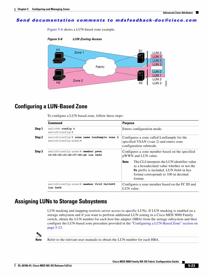
Send documenta t ion comments to mdsfeedback -doc@c i sco .com
Chapter 5 Configuring and Managing ZonesAdvanced Zone Attributes
Figure 5-6 shows a LUN-based zone example.
Figure 5-6 LUN Zoning Access
Configuring a LUN-Based ZoneTo configure a LUN-based zone, follow these steps:
Assigning LUNs to Storage SubsystemsLUN masking and mapping restricts server access to specific LUNs. If LUN masking is enabled on a storage subsystem and if you want to perform additional LUN zoning in a Cisco MDS 9000 Family switch, obtain the LUN number for each host bus adapter (HBA) from the storage subsystem and then configure the LUN-based zone procedure provided in the “Configuring a LUN-Based Zone” section on page 5-23.
Note Refer to the relevant user manuals to obtain the LUN number for each HBA.
S1
H1 S1
S2H2
Zone 1
Zone 2
Zone 2
7954
0
Fabric
LUN 0LUN 1LUN 2LUN 3
LUN 0LUN 1LUN 2LUN 3
Command Purpose
Step 1 switch# config tswitch(config)#
Enters configuration mode.
Step 2 switch(config)# zone name LunSample vsan 2switch(config-zone)#
Configures a zone called LunSample for the specified VSAN (vsan 2) and enters zone configuration submode.
Step 3 switch(config-zone)# member pwwn 10:00:00:23:45:67:89:ab lun 0x64
Configures a zone member based on the specified pWWN and LUN value.
Note The CLI interprets the LUN identifier value as a hexadecimal value whether or not the 0x prefix is included. LUN 0x64 in hex format corresponds to 100 in decimal format.
switch(config-zone)# member fcid 0x12465 lun 0x64
Configures a zone member based on the FC ID and LUN value.
5-23Cisco MDS 9000 Family NX-OS Fabric Configuration Guide
OL-20706-01, Cisco MDS NX-OS Release 5.0(1a)

Send documenta t ion comments to mdsfeedback -doc@c i sco .com
Chapter 5 Configuring and Managing ZonesAdvanced Zone Attributes
Caution If you make any errors when assigning LUNs, you might lose data.
About Read-Only ZonesBy default, an initiator has both read and write access to the target's media when they are members of the same Fibre Channel zone. The read-only zone feature allows members to have only read access to the media within a read-only Fibre Channel zone.
You can also configure LUN zones as read-only zones. Any zone can be identified as a read-only zone. By default all zones have read-write permission unless explicitly configured as a read-only zone.
Follow these guidelines when configuring read-only zones:
• If read-only zones are implemented, the switch prevents write access to user data within the zone.
• If two members belong to a read-only zone and to a read-write zone, the read-only zone takes priority and write access is denied.
• LUN zoning can only be implemented in Cisco MDS 9000 Family switches. If LUN zoning is implemented in a switch, you cannot configure interop mode in that switch.
• Read-only volumes are not supported by some operating system and file system combinations (for example, Windows NT or Windows 2000 and NTFS file system). Volumes within read-only zones are not available to such hosts. However, if these hosts are already booted when the read-only zones are activated, then read-only volumes are available to those hosts.
The read-only zone feature behaves as designed if either the FAT16 or FAT32 file system is used with the previously mentioned Windows operating systems.
Configuring Read-Only ZonesTo configure read-only zones, follow these steps:
To configure the read-only option for a default zone, follow these steps:
Command Purpose
Step 1 switch# config t switch(config)#
Enters configuration mode.
Step 2 switch(config)# zone name Sample2 vsan 2switch(config-zone)#
Configures a zone called Sample2 for the specified VSAN (vsan 2) and enters zone configuration submode.
Step 3 switch(config-zone)# attribute read-only Sets read-only attributes for the Sample2 zone.
Note The default is read-write for all zones.
switch(config-zone)# no attribute read-only
Reverts the Sample2 zone attributes to read-write.
Command Purpose
Step 1 switch# config t switch(config)#
Enters configuration mode.
Step 2 switch(config)# zone default-zone vsan 1switch(config-default-zone)#
Enters the default zone configuration submode.
5-24Cisco MDS 9000 Family NX-OS Fabric Configuration Guide
OL-20706-01, Cisco MDS NX-OS Release 5.0(1a)
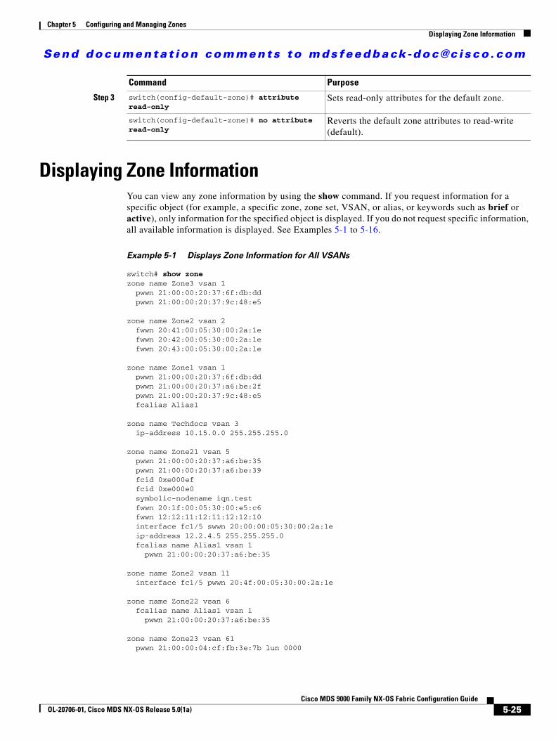
Send documenta t ion comments to mdsfeedback -doc@c i sco .com
Chapter 5 Configuring and Managing ZonesDisplaying Zone Information
Displaying Zone InformationYou can view any zone information by using the show command. If you request information for a specific object (for example, a specific zone, zone set, VSAN, or alias, or keywords such as brief or active), only information for the specified object is displayed. If you do not request specific information, all available information is displayed. See Examples 5-1 to 5-16.
Example 5-1 Displays Zone Information for All VSANs
switch# show zone zone name Zone3 vsan 1
pwwn 21:00:00:20:37:6f:db:ddpwwn 21:00:00:20:37:9c:48:e5
zone name Zone2 vsan 2 fwwn 20:41:00:05:30:00:2a:1e fwwn 20:42:00:05:30:00:2a:1e fwwn 20:43:00:05:30:00:2a:1e
zone name Zone1 vsan 1 pwwn 21:00:00:20:37:6f:db:dd pwwn 21:00:00:20:37:a6:be:2f pwwn 21:00:00:20:37:9c:48:e5 fcalias Alias1
zone name Techdocs vsan 3 ip-address 10.15.0.0 255.255.255.0
zone name Zone21 vsan 5 pwwn 21:00:00:20:37:a6:be:35 pwwn 21:00:00:20:37:a6:be:39 fcid 0xe000ef fcid 0xe000e0 symbolic-nodename iqn.test fwwn 20:1f:00:05:30:00:e5:c6 fwwn 12:12:11:12:11:12:12:10 interface fc1/5 swwn 20:00:00:05:30:00:2a:1e ip-address 12.2.4.5 255.255.255.0 fcalias name Alias1 vsan 1 pwwn 21:00:00:20:37:a6:be:35
zone name Zone2 vsan 11interface fc1/5 pwwn 20:4f:00:05:30:00:2a:1e
zone name Zone22 vsan 6 fcalias name Alias1 vsan 1 pwwn 21:00:00:20:37:a6:be:35
zone name Zone23 vsan 61 pwwn 21:00:00:04:cf:fb:3e:7b lun 0000
Step 3 switch(config-default-zone)# attribute read-only
Sets read-only attributes for the default zone.
switch(config-default-zone)# no attribute read-only
Reverts the default zone attributes to read-write (default).
Command Purpose
5-25Cisco MDS 9000 Family NX-OS Fabric Configuration Guide
OL-20706-01, Cisco MDS NX-OS Release 5.0(1a)

Send documenta t ion comments to mdsfeedback -doc@c i sco .com
Chapter 5 Configuring and Managing ZonesDisplaying Zone Information
Example 5-2 Displays Zone Information for a Specific VSAN
switch# show zone vsan 1zone name Zone3 vsan 1 pwwn 21:00:00:20:37:6f:db:dd pwwn 21:00:00:20:37:9c:48:e5
zone name Zone2 vsan 1 fwwn 20:4f:00:05:30:00:2a:1e fwwn 20:50:00:05:30:00:2a:1e fwwn 20:51:00:05:30:00:2a:1e fwwn 20:52:00:05:30:00:2a:1e fwwn 20:53:00:05:30:00:2a:1e
zone name Zone1 vsan 1 pwwn 21:00:00:20:37:6f:db:dd pwwn 21:00:00:20:37:a6:be:2f pwwn 21:00:00:20:37:9c:48:e5 fcalias Alias1
Use the show zoneset command to view the configured zone sets.
Example 5-3 Displays Configured Zone Set Information
switch# show zoneset vsan 1zoneset name ZoneSet2 vsan 1 zone name Zone2 vsan 1 fwwn 20:4e:00:05:30:00:2a:1e fwwn 20:4f:00:05:30:00:2a:1e fwwn 20:50:00:05:30:00:2a:1e fwwn 20:51:00:05:30:00:2a:1e fwwn 20:52:00:05:30:00:2a:1e
zone name Zone1 vsan 1 pwwn 21:00:00:20:37:6f:db:dd pwwn 21:00:00:20:37:a6:be:2f pwwn 21:00:00:20:37:9c:48:e5 fcalias Alias1
zoneset name ZoneSet1 vsan 1 zone name Zone1 vsan 1 pwwn 21:00:00:20:37:6f:db:dd pwwn 21:00:00:20:37:a6:be:2f pwwn 21:00:00:20:37:9c:48:e5 fcalias Alias1
Example 5-4 Displays Configured Zone Set Information for a Range of VSANs
switch# show zoneset vsan 2-3zoneset name ZoneSet2 vsan 2 zone name Zone2 vsan 2 fwwn 20:52:00:05:30:00:2a:1e fwwn 20:53:00:05:30:00:2a:1e fwwn 20:54:00:05:30:00:2a:1e fwwn 20:55:00:05:30:00:2a:1e fwwn 20:56:00:05:30:00:2a:1e
zone name Zone1 vsan 2 pwwn 21:00:00:20:37:6f:db:dd pwwn 21:00:00:20:37:a6:be:2f pwwn 21:00:00:20:37:9c:48:e5 fcalias Alias1
5-26Cisco MDS 9000 Family NX-OS Fabric Configuration Guide
OL-20706-01, Cisco MDS NX-OS Release 5.0(1a)

Send documenta t ion comments to mdsfeedback -doc@c i sco .com
Chapter 5 Configuring and Managing ZonesDisplaying Zone Information
zoneset name ZoneSet3 vsan 3 zone name Zone1 vsan 1 pwwn 21:00:00:20:37:6f:db:dd pwwn 21:00:00:20:37:a6:be:2f pwwn 21:00:00:20:37:9c:48:e5 fcalias Alias1
Use the show zone name command to display members of a specific zone.
Example 5-5 Displays Members of a Zone
switch# show zone name Zone1 zone name Zone1 vsan 1 pwwn 21:00:00:20:37:6f:db:dd pwwn 21:00:00:20:37:a6:be:2f pwwn 21:00:00:20:37:9c:48:e5 fcalias Alias1
Use the show fcalias command to display fcalias configuration.
Example 5-6 Displays fcalias Configuration
switch# show fcalias vsan 1fcalias name Alias2 vsan 1
fcalias name Alias1 vsan 1 pwwn 21:00:00:20:37:6f:db:dd pwwn 21:00:00:20:37:9c:48:e5
Use the show zone member command to display all zones to which a member belongs using the FC ID.
Example 5-7 Displays Membership Status
switch# show zone member pwwn 21:00:00:20:37:9c:48:e5 VSAN: 1zone Zone3zone Zone1fcalias Alias1
Use the show zone statistics command to display the number of control frames exchanged with other switches.
Example 5-8 Displays Zone Statistics
switch# show zone statistics Statistics For VSAN: 1**********************************Number of Merge Requests Sent: 24Number of Merge Requests Recvd: 25Number of Merge Accepts Sent: 25Number of Merge Accepts Recvd: 25Number of Merge Rejects Sent: 0Number of Merge Rejects Recvd: 0Number of Change Requests Sent: 0Number of Change Requests Recvd: 0Number of Change Rejects Sent: 0Number of Change Rejects Recvd: 0Number of GS Requests Recvd: 0Number of GS Requests Rejected: 0
5-27Cisco MDS 9000 Family NX-OS Fabric Configuration Guide
OL-20706-01, Cisco MDS NX-OS Release 5.0(1a)

Send documenta t ion comments to mdsfeedback -doc@c i sco .com
Chapter 5 Configuring and Managing ZonesDisplaying Zone Information
Statistics For VSAN: 2**********************************Number of Merge Requests Sent: 4Number of Merge Requests Recvd: 4Number of Merge Accepts Sent: 4Number of Merge Accepts Recvd: 4Number of Merge Rejects Sent: 0Number of Merge Rejects Recvd: 0Number of Change Requests Sent: 0Number of Change Requests Recvd: 0Number of Change Rejects Sent: 0Number of Change Rejects Recvd: 0Number of GS Requests Recvd: 0Number of GS Requests Rejected: 0
Example 5-9 Displays LUN Zone Statistics
switch# show zone statistics lun-zoningLUN zoning statistics for VSAN: 1************************************************************S-ID: 0x123456, D-ID: 0x22222, LUN: 00:00:00:00:00:00:00:00------------------------------------------------------------Number of Inquiry commands received: 10Number of Inquiry data No LU sent: 5Number of Report LUNs commands received: 10Number of Request Sense commands received: 1Number of Other commands received: 0Number of Illegal Request Check Condition sent: 0
S-ID: 0x123456, D-ID: 0x22222, LUN: 00:00:00:00:00:00:00:01------------------------------------------------------------Number of Inquiry commands received: 1Number of Inquiry data No LU sent: 1Number of Request Sense commands received: 1Number of Other commands received: 0Number of Illegal Request Check Condition sent: 0
Example 5-10 Displays LUN Zone Statistics
switch# show zone statistics read-only-zoningRead-only zoning statistics for VSAN: 2************************************************************S-ID: 0x33333, D-ID: 0x11111, LUN: 00:00:00:00:00:00:00:64------------------------------------------------------------Number of Data Protect Check Condition Sent: 12
Example 5-11 Displays Active Zone Sets
switch# show zoneset active zoneset name ZoneSet1 vsan 1 zone name zone1 vsan 1 fcid 0x080808 fcid 0x090909 fcid 0x0a0a0a zone name zone2 vsan 1 * fcid 0xef0000 [pwwn 21:00:00:20:37:6f:db:dd] * fcid 0xef0100 [pwwn 21:00:00:20:37:a6:be:2f]
5-28Cisco MDS 9000 Family NX-OS Fabric Configuration Guide
OL-20706-01, Cisco MDS NX-OS Release 5.0(1a)
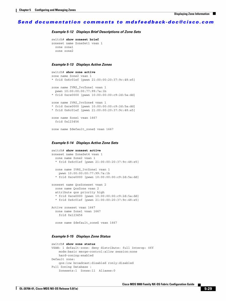
Send documenta t ion comments to mdsfeedback -doc@c i sco .com
Chapter 5 Configuring and Managing ZonesDisplaying Zone Information
Example 5-12 Displays Brief Descriptions of Zone Sets
switch# show zoneset briefzoneset name ZoneSet1 vsan 1 zone zone1 zone zone2
Example 5-13 Displays Active Zones
switch# show zone active zone name Zone2 vsan 1* fcid 0x6c01ef [pwwn 21:00:00:20:37:9c:48:e5]
zone name IVRZ_IvrZone1 vsan 1 pwwn 10:00:00:00:77:99:7a:1b* fcid 0xce0000 [pwwn 10:00:00:00:c9:2d:5a:dd]
zone name IVRZ_IvrZone4 vsan 1* fcid 0xce0000 [pwwn 10:00:00:00:c9:2d:5a:dd]* fcid 0x6c01ef [pwwn 21:00:00:20:37:9c:48:e5]
zone name Zone1 vsan 1667 fcid 0x123456
zone name $default_zone$ vsan 1667
Example 5-14 Displays Active Zone Sets
switch# show zoneset active zoneset name ZoneSet4 vsan 1 zone name Zone2 vsan 1 * fcid 0x6c01ef [pwwn 21:00:00:20:37:9c:48:e5]
zone name IVRZ_IvrZone1 vsan 1 pwwn 10:00:00:00:77:99:7a:1b * fcid 0xce0000 [pwwn 10:00:00:00:c9:2d:5a:dd]
zoneset name QosZoneset vsan 2zone name QosZone vsan 2attribute qos priority high
* fcid 0xce0000 [pwwn 10:00:00:00:c9:2d:5a:dd] * fcid 0x6c01ef [pwwn 21:00:00:20:37:9c:48:e5]
Active zoneset vsan 1667 zone name Zone1 vsan 1667 fcid 0x123456
zone name $default_zone$ vsan 1667
Example 5-15 Displays Zone Status
switch# show zone statusVSAN: 1 default-zone: deny distribute: full Interop: Off
mode:basic merge-control:allow session:none hard-zoning:enabledDefault zone: qos:low broadcast:disabled ronly:disabledFull Zoning Database : Zonesets:1 Zones:11 Aliases:0
5-29Cisco MDS 9000 Family NX-OS Fabric Configuration Guide
OL-20706-01, Cisco MDS NX-OS Release 5.0(1a)

Send documenta t ion comments to mdsfeedback -doc@c i sco .com
Chapter 5 Configuring and Managing ZonesDisplaying Zone Information
Active Zoning Database : Name: zoneset-1 Zonesets:1 Zones:11 Aliases:0Status: Activation completed at Thu Feb 13 10:22:34 2003
VSAN: 2 default-zone: deny distribute: full Interop: Offmode:basic merge-control:allow session:none
hard-zoning:enabledDefault zone: qos:low broadcast:disabled ronly:disabledFull Zoning Database : Zonesets:1 Zones:10 Aliases:0Active Zoning Database : Name: zoneset-2 Zonesets:1 Zones:10 Aliases:0Status: Activation completed at Thu Feb 13 10:23:12 2003
VSAN: 3 default-zone: deny distribute: full Interop: Offmode:basic merge-control:allow session:none
hard-zoning:enabledDefault zone: qos:low broadcast:disabled ronly:disabledFull Zoning Database : Zonesets:1 Zones:10 Aliases:0Active Zoning Database : Name: zoneset-3 Zonesets:1 Zones:10 Aliases:0Status: Activation completed at Thu Feb 13 10:23:50 2003
Use the show zone command to display the zone attributes for all configured zones.
Example 5-16 Displays Zone Statistics
switch# show zone zone name lunSample vsan 1 <-----------------Read-write attribute zone name ReadOnlyZone vsan 2 attribute read-only <-----------------Read-only attribute
Use the show running and show zone active commands to display the configured interface-based zones (see Example 5-17 and Example 5-18).
Example 5-17 Displays the Interface-Based Zones
switch# show runningzone name if-zone vsan 1 member interface fc2/15 swwn 20:00:00:0c:88:00:4a:e2 member fwwn 20:4f:00:0c:88:00:4a:e2 member interface fc2/1 swwn 20:00:00:05:30:00:4a:9e member pwwn 22:00:00:20:37:39:6b:dd
Example 5-18 Displays the fWWNs and Interfaces in an Active Zone
switch# show zone activezone name if-zone vsan 1 * fcid 0x7e00b3 [interface fc2/15 swwn 20:00:00:0c:88:00:4a:e2] * fcid 0x7e00b1 [interface fc2/15 swwn 20:00:00:0c:88:00:4a:e2] * fcid 0x7e00ac [interface fc2/15 swwn 20:00:00:0c:88:00:4a:e2] * fcid 0x7e00b3 [fwwn 20:4f:00:0c:88:00:4a:e2] * fcid 0x7e00b1 [fwwn 20:4f:00:0c:88:00:4a:e2] * fcid 0x7e00ac [fwwn 20:4f:00:0c:88:00:4a:e2] interface fc2/1 swwn 20:00:00:05:30:00:4a:9e
A similar output is also available on the remote switch (see Example 5-19).
5-30Cisco MDS 9000 Family NX-OS Fabric Configuration Guide
OL-20706-01, Cisco MDS NX-OS Release 5.0(1a)

Send documenta t ion comments to mdsfeedback -doc@c i sco .com
Chapter 5 Configuring and Managing ZonesEnhanced Zoning
Example 5-19 Displays the Local Interface Active Zone Details for a Remote Switch
switch# show zone activezone name if-zone vsan 1 * fcid 0x7e00b3 [interface fc2/15 swwn 20:00:00:0c:88:00:4a:e2] * fcid 0x7e00b1 [interface fc2/15 swwn 20:00:00:0c:88:00:4a:e2] * fcid 0x7e00ac [interface fc2/15 swwn 20:00:00:0c:88:00:4a:e2] * fcid 0x7e00b3 [fwwn 20:4f:00:0c:88:00:4a:e2] * fcid 0x7e00b1 [fwwn 20:4f:00:0c:88:00:4a:e2] * fcid 0x7e00ac [fwwn 20:4f:00:0c:88:00:4a:e2] interface fc2/1 swwn 20:00:00:05:30:00:4a:9e
Enhanced ZoningThe zoning feature complies with the FC-GS-4 and FC-SW-3 standards. Both standards support the basic zoning functionalities explained in the previous section and the enhanced zoning functionalities described in this section.
This section includes the following topics:
• About Enhanced Zoning, page 5-31
• Changing from Basic Zoning to Enhanced Zoning, page 5-32
• Changing from Enhanced Zoning to Basic Zoning, page 5-33
• Enabling Enhanced Zoning, page 5-33
• Modifying the Zone Database, page 5-34
• Releasing Zone Database Locks, page 5-34
• Creating Attribute Groups, page 5-34
• Merging the Database, page 5-35
• Configuring Zone Merge Control Policies, page 5-36
• Permitting or Denying Traffic in the Default Zone, page 5-36
• Broadcasting a Zone, page 5-37
• Configuring System Default Zoning Settings, page 5-38
• Displaying Enhanced Zone Information, page 5-39
About Enhanced ZoningTable 5-3 lists the advantages of the enhanced zoning feature in all switches in the Cisco MDS 9000 Family.
5-31Cisco MDS 9000 Family NX-OS Fabric Configuration Guide
OL-20706-01, Cisco MDS NX-OS Release 5.0(1a)

Send documenta t ion comments to mdsfeedback -doc@c i sco .com
Chapter 5 Configuring and Managing ZonesEnhanced Zoning
Changing from Basic Zoning to Enhanced ZoningTo change to the enhanced zoning mode from the basic mode, follow these steps:
Step 1 Verify that all switches in the fabric are capable of working in the enhanced mode.
If one or more switches are not capable of working in enhanced mode, then your request to move to enhanced mode is rejected.
Step 2 Set the operation mode to enhanced zoning mode. By doing so, you will automatically start a session, acquire a fabric wide lock, distribute the active and full zoning database using the enhanced zoning data structures, distribute zoning policies and then release the lock. All switches in the fabric then move to the enhanced zoning mode.
Table 5-3 Advantages of Enhanced Zoning
Basic Zoning Enhanced Zoning Enhanced Zoning Advantages
Administrators can make simultaneous configuration changes. Upon activation, one administrator can overwrite another administrator’s changes.
Performs all configurations within a single configuration session. When you begin a session, the switch locks the entire fabric to implement the change.
One configuration session for the entire fabric to ensure consistency within the fabric.
If a zone is part of multiple zone sets, you create an instance of this zone in each zone set.
References to the zone are used by the zone sets as required once you define the zone.
Reduced payload size as the zone is referenced. The size is more pronounced with bigger databases.
The default zone policy is defined per switch. To ensure smooth fabric operation, all switches in the fabric must have the same default zone setting.
Enforces and exchanges the default zone setting throughout the fabric.
Fabric-wide policy enforcement reduces troubleshooting time.
To retrieve the results of the activation on a per switch basis, the managing switch provides a combined status about the activation. It does not identify the failure switch.
Retrieves the activation results and the nature of the problem from each remote switch.
Enhanced error reporting eases the troubleshooting process.
To distribute the zoning database, you must reactivate the same zone set. The reactivation may affect hardware changes for hard zoning on the local switch and on remote switches.
Implements changes to the zoning database and distributes it without reactivation.
Distribution of zone sets without activation avoids hardware changes for hard zoning in the switches.
The MDS-specific zone member types (IPv4 address, IPv6 address, symbolic node name, and other types) may be used by other non-Cisco switches. During a merge, the MDS-specific types can be misunderstood by the non-Cisco switches.
Provides a vendor ID along with a vendor-specific type value to uniquely identify a member type.
Unique vendor type.
The fWWN-based zone membership is only supported in Cisco interop mode.
Supports fWWN-based membership in the standard interop mode (interop mode 1).
The fWWN-based member type is standardized.
5-32Cisco MDS 9000 Family NX-OS Fabric Configuration Guide
OL-20706-01, Cisco MDS NX-OS Release 5.0(1a)

Send documenta t ion comments to mdsfeedback -doc@c i sco .com
Chapter 5 Configuring and Managing ZonesEnhanced Zoning
Tip After moving from basic zoning to enhanced zoning, we recommend that you save the running configuration.
Changing from Enhanced Zoning to Basic ZoningThe standards do not allow you to move back to basic zoning. However, Cisco MDS switches allow this move to enable you to downgrade and upgrade to other Cisco SAN-OS or Cisco NX-OS releases.
To change to the basic zoning mode from the enhanced mode, follow these steps:
Step 1 Verify that the active and full zone set do not contain any configuration that is specific to the enhanced zoning mode.
If such configurations exist, delete them before proceeding with this procedure. If you do not delete the existing configuration, the Cisco NX-OS software automatically removes them.
Step 2 Set the operation mode to basic zoning mode. By doing so, you will automatically start a session, acquire a fabric wide lock, distribute the zoning information using the basic zoning data structure, apply the configuration changes and release the lock from all switches in the fabric. All switches in the fabric then move to basic zoning mode.
Note If a switch running Cisco SAN-OS Release 2.0(1b) and NX-OS 4(1b) or later, with enhanced zoning enabled is downgraded to Cisco SAN-OS Release 1.3(4), or earlier, the switch comes up in basic zoning mode and cannot join the fabric because all the other switches in the fabric are still in enhanced zoning mode.
Enabling Enhanced ZoningBy default, the enhanced zoning feature is disabled in all switches in the Cisco MDS 9000 Family.
To enable enhanced zoning in a VSAN, follow these steps:
Command Purpose
Step 1 switch# config t switch(config)#
Enters configuration mode.
Step 2 switch(config)# zone mode enhanced vsan 3000Set zoning mode command initiated. Check zone status
Enables enhanced zoning in the specified VSAN.
switch(config)# no zone mode enhanced vsan 150Set zoning mode command initiated. Check zone status
Disables enhanced zoning in the specified VSAN.
5-33Cisco MDS 9000 Family NX-OS Fabric Configuration Guide
OL-20706-01, Cisco MDS NX-OS Release 5.0(1a)

Send documenta t ion comments to mdsfeedback -doc@c i sco .com
Chapter 5 Configuring and Managing ZonesEnhanced Zoning
Modifying the Zone DatabaseModifications to the zone database is done within a session. A session is created at the time of the first successful configuration command. On creation of a session, a copy of the zone database is created. Any changes done within the session are performed on this copy of the zoning database. These changes in the copy zoning database are not applied to the effective zoning database until you commit the changes. Once you apply the changes, the session is closed.
If the fabric is locked by another user and for some reason the lock is not cleared, you can force the operation and close the session. You must have permission (role) to clear the lock in this switch and perform the operation on the switch from where the session was originally created.
To commit or discard changes to the zoning database in a VSAN, follow these steps:
Releasing Zone Database LocksTo release the session lock on the zoning database on the switches in a VSAN, use the no zone commit vsan command from the switch where the database was initially locked.
switch# config tswitch(config)# no zone commit vsan 2
If session locks remain on remote switches after using the no zone commit vsan command, you can use the clear zone lock vsan command on the remote switches.
switch# clear zone lock vsan 2
Note We recommend using the no zone commit vsan command first to release the session lock in the fabric. If that fails, use the clear zone lock vsan command on the remote switches where the session is still locked.
Creating Attribute GroupsIn enhanced mode, you can directly configure attributes using attribute groups.
To configure attribute groups, follow these steps:
Command Purpose
Step 1 switch# config t switch(config)#
Enters configuration mode.
Step 2 switch(config)# zone commit vsan 2 No pending info found
Applies the changes to the enhanced zone database and closes the session.
switch(config)# zone commit vsan 3 force Forcefully applies the changes to the enhanced zone database and closes the session created by another user.
switch(config)# no zone commit vsan 2 Discards the changes to the enhanced zone database and closes the session.
switch(config)# no zone commit vsan 3 force Forcefully discards the changes to the enhanced zone database and closes the session created by another user.
5-34Cisco MDS 9000 Family NX-OS Fabric Configuration Guide
OL-20706-01, Cisco MDS NX-OS Release 5.0(1a)

Send documenta t ion comments to mdsfeedback -doc@c i sco .com
Chapter 5 Configuring and Managing ZonesEnhanced Zoning
Step 1 Create an attribute group.
switch# conf tswitch(config)# zone-attribute-group name SampleAttributeGroup vsan 2switch(config-attribute-group)#
Step 2 Add the attribute to an attribute-group object.
switch(config-attribute-group)# readonlyswitch(config-attribute-group)# broadcastswitch(config-attribute-group)# qos priority medium
Step 3 Attach the attribute-group to a zone.
switch(config)# zone name Zone1 vsan 2switch(config-zone)# attribute-group SampleAttributeGroupswitch(config-zone)# exitswitch(config)#
Step 4 Activate the zone set.
switch(config)# zoneset activate name Zoneset1 vsan 2
The attribute-groups are expanded and only the configured attributes are present in the active zone set.
Merging the Database The merge behavior depends on the fabric-wide merge control setting:
• Restrict—If the two databases are not identical, the ISLs between the switches are isolated.
• Allow—The two databases are merged using the merge rules specified in Table 5-4.
Table 5-4 Database Zone Merge Status
Local Database Adjacent Database Merge Status Results of the Merge
The databases contain zone sets with the same name1 but different zones, aliases, and attributes groups.
1. In the enhanced zoning mode, the active zone set does not have a name in interop mode 1. The zone set names are only present for full zone sets.
Successful. The union of the local and adjacent databases.
The databases contains a zone, zone alias, or zone attribute group object with same name1 but different members.
Failed. ISLs are isolated.
Empty. Contains data. Successful. The adjacent database information populates the local database.
Contains data. Empty. Successful. The local database information populates the adjacent database.
5-35Cisco MDS 9000 Family NX-OS Fabric Configuration Guide
OL-20706-01, Cisco MDS NX-OS Release 5.0(1a)

Send documenta t ion comments to mdsfeedback -doc@c i sco .com
Chapter 5 Configuring and Managing ZonesEnhanced Zoning
Caution Remove all non-pWWN-type zone entries on all MDS switches running Cisco SAN-OS prior to merging fabrics if there is a Cisco MDS 9020 switch running FabricWare in the adjacent fabric.
Merge Process
The merge process operates as follows:
1. The software compares the protocol versions. If the protocol versions differ, then the ISL is isolated.
2. If the protocol versions are the same, then the zone policies are compared. If the zone policies differ, then the ISL is isolated.
3. If the zone merge options are the same, then the comparison is implemented based on the merge control setting.
a. If the setting is restrict, the active zone set and the full zone set should be identical. Otherwise the link is isolated.
b. If the setting is allow, then the merge rules are used to perform the merge.
Configuring Zone Merge Control PoliciesTo configure merge control policies, follow these steps:
Preventing Zones From Flooding FC2 BuffersBy using the zone fc2 merge throttle enable command you can throttle the merge requests that are sent from zones to FC2 and prevent zones from flooding FC2 buffers. This command is enabled by default. This command can be used to prevent any zone merge scalability problem when you have a lot of zones. Use the show zone status command to view zone merge throttle information.
Permitting or Denying Traffic in the Default ZoneTo permit or deny traffic in the default zone, follow these steps:
Command Purpose
Step 1 switch# config t switch(config)#
Enters configuration mode.
Step 2 switch(config)# zone merge-control restrict vsan 4
Configures a restricted merge control setting for this VSAN.
switch(config)# no zone merge-control restrict vsan 2
Defaults to using the allow merge control setting for this VSAN.
switch(config)# zone commit vsan 4 Commits the changes made to VSAN 4.
Command Purpose
Step 1 switch# config t Enters configuration mode.
5-36Cisco MDS 9000 Family NX-OS Fabric Configuration Guide
OL-20706-01, Cisco MDS NX-OS Release 5.0(1a)

Send documenta t ion comments to mdsfeedback -doc@c i sco .com
Chapter 5 Configuring and Managing ZonesEnhanced Zoning
Broadcasting a ZoneYou can specify an enhanced zone to restrict broadcast frames generated by a member in this zone to members within that zone. Use this feature when the host or storage devices support broadcasting.
Table 5-5 identifies the rules for the delivery of broadcast frames.
Tip If any NL port attached to an FL port shares a broadcast zone with the source of the broadcast frame, then the frames are broadcast to all devices in the loop.
To broadcast frames in the enhanced zoning mode, follow these steps:
Step 2 switch(config)# zone default-zone permit vsan 5 Permits traffic flow to default zone members.
switch(config)# no zone default-zone permit vsan 3 Denies traffic flow to default zone members and reverts to factory default.
Step 3 switch(config)# zone commit vsan 5 Commits the changes made to VSAN 5.
Command Purpose
Table 5-5 Broadcasting Requirements
Active Zoning? Broadcast Enabled? Frames Broadcast? Comments
Yes Yes Yes Broadcast to all Nx ports that share a broadcast zone with the source of broadcast frames.
No Yes Yes Broadcast to all Nx ports.
Yes No No Broadcasting is disabled.
Command Purpose
Step 1 switch# config t switch(config)#
Enters configuration mode.
Step 2 switch(config)# zone-attribute-group name BroadcastAttr vsan 2
Configures the zone attribute group for the required VSAN.
switch(config)# no zone-attribute-group name BroadAttr vsan 1
Removes the zone attribute group for the required VSAN.
Step 3 switch(config-attribute-group)# broadcastswitch(config-attribute-group)# exitswitch(config)#
Creates a broadcast attribute for this group and exits this submode.
switch(config-attribute-group)# no broadcast Removes broadcast attribute for this group and exits this submode.
Step 4 switch(config)# zone name BroadcastAttr vsan 2switch(config-zone)#
Configures a zone named BroadcastAttr in VSAN 2.
5-37Cisco MDS 9000 Family NX-OS Fabric Configuration Guide
OL-20706-01, Cisco MDS NX-OS Release 5.0(1a)

Send documenta t ion comments to mdsfeedback -doc@c i sco .com
Chapter 5 Configuring and Managing ZonesEnhanced Zoning
Configuring System Default Zoning SettingsYou can configure default settings for default zone policies, full zone distribution, and generic service permissions for new VSANs on the switch. To configure switch-wide default settings, follow these steps:
Step 5 switch(config-zone)# member pwwn 21:00:00:e0:8b:0b:66:56switch(config-zone)# member pwwn 21:01:00:e0:8b:2e:80:93switch(config-zone)# attribute-group name BroadcastAttrswitch(config-zone)# exitswitch(config)#
Adds the specified members to this zone and exits this submode.
Step 6 switch(config)# zone commit vsan 1Commit operation initiatedswitch(config)# end
Applies the changes to the enhanced zone configuration and exits this submode.
Step 7 switch# show zone vsan 1zone name BroadcastAttr vsan 1zone-attribute-group name BroadcastAttr vsan 1broadcastpwwn 21:00:00:e0:8b:0b:66:56pwwn 21:01:00:e0:8b:2e:80:93
Displays the broadcast configuration
Command Purpose
Command Purpose
Step 1 switch# config t Enters configuration mode.
Step 2 switch(config)# system default zone default-zone permit
Configures permit as the default zoning policy for new VSANs on the switch.
switch(config)# no system default zone default-zone permit
Configures deny (default) as the default zoning policy for new VSANs on the switch.
Step 3 switch(config)# system default zone distribute full
Enables full zone database distribution as the default for new VSANs on the switch.
switch(config)# no system default zone distribute full
Disables (default) full zone database distribution as the default for new VSANs on the switch. Only the active zone database is distributed.
Step 4 switch(config)# system default zone gs read Configures read only as the default generic service permission for new VSANs on the switch.
switch(config)# system default zone gs read-write Configures (default) read-write as the default generic service permission for new VSANs on the switch.
switch(config)# no system default zone gs read-write
Configures none(deny) as the default generic service permission for new VSANs on the switch.
5-38Cisco MDS 9000 Family NX-OS Fabric Configuration Guide
OL-20706-01, Cisco MDS NX-OS Release 5.0(1a)

Send documenta t ion comments to mdsfeedback -doc@c i sco .com
Chapter 5 Configuring and Managing ZonesEnhanced Zoning
Note Since VSAN 1 is the default VSAN and is always present on the switch, the system default zone commands have no effect on VSAN 1.
Configuring Zone Generic Service Permission SettingsZone generic service permission setting is used to control zoning operation through generic service (GS) interface. The zone generic service permission can be read-only, read-write or none (deny).
To configure generic service (GS) settings, follow these steps:
Displaying Enhanced Zone InformationYou can view any zone information by using the show command. See Examples 5-20 to 5-32.
Example 5-20 Displays the Active Zone Set Information for a Specified VSAN
switch# show zoneset active vsan 2zoneset name testzoneset vsan 2 zone name testzone vsan 2 attribute read-only attribute broadcast attribute qos priority high pwwn 21:01:00:e0:8b:2e:a3:8a pwwn 22:00:00:0c:50:02:cb:59
zone name $default_zone$ vsan 2 attribute read-only attribute qos priority high attribute broadcast]
Example 5-21 Displays the Zone Set Information or a Specified VSAN
switch# show zoneset vsan 2zoneset name testzoneset vsan 2 zone name testzone vsan 2 zone-attribute-group name testattgp vsan 2 read-only broadcast qos priority high pwwn 21:01:00:e0:8b:2e:a3:8a pwwn 22:00:00:0c:50:02:cb:59
Command Purpose
Step 1 switch# config t Enters configuration mode.
Step 2 switch(config)# zone gs read vsan 3000 Configures gs permission value as read only in the specified vsan.
switch(config)# zone gs read-write vsan 3000 Configures gs permission value as read-write in the specified vsan.
switch(config)# no zone gs read-write vsan 3000 Configures gs permission value as none(deny) in the specified vsan.
5-39Cisco MDS 9000 Family NX-OS Fabric Configuration Guide
OL-20706-01, Cisco MDS NX-OS Release 5.0(1a)

Send documenta t ion comments to mdsfeedback -doc@c i sco .com
Chapter 5 Configuring and Managing ZonesEnhanced Zoning
zoneset name testzoneset2 vsan 2 zone name testzone2 vsan 2 pwwn 21:01:00:e0:8b:2e:68:8a pwwn 22:00:00:0c:50:02:cb:80
zoneset name testzoneset3 vsan 2 zone name testzone3 vsan 2 pwwn 21:01:00:e0:8b:2e:68:8a pwwn 22:00:00:0c:50:02:cb:80
Example 5-22 Displays the Zone Attribute Group Information for a Specified VSAN
switch# show zone-attribute-group vsan 2zone-attribute-group name $default_zone_attr_group$ vsan 2 read-only qos priority high broadcastzone-attribute-group name testattgp vsan 2 read-only broadcast qos priority high
Example 5-23 Displays the fcalias Information for the Specified VSAN
switch# show fcalias vsan 2fcalias name testfcalias vsan 2 pwwn 21:00:00:20:37:39:b0:f4 pwwn 21:00:00:20:37:6f:db:dd pwwn 21:00:00:20:37:a6:be:2f
Example 5-24 Displays the Zone Status for the Specified VSAN
switch# show zone status vsan 2VSAN: 2 default-zone: permit distribute: active only Interop: 100
mode:basic merge-control:allow session:none hard-zoning:enabledDefault zone: qos:low broadcast:disabled ronly:disabledFull Zoning Database : Zonesets:3 Zones:3 Aliases: 0 Attribute-groups: 2Active Zoning Database : Name: testzoneset Zonesets:1 Zones:2Status:
Example 5-25 Displays an Active Zone Status for the Specified VSAN
switch# show zone status vsan 1VSAN: 1 default-zone: permit distribute: full Interop: 100
mode: enhanced merge-control: allow session: active <--------Indicates an active session.Hard zoning is enabled
Default zone: qos:low broadcast:disabled ronly:disabledFull Zoning Database : Zonesets:4 Zones:4 Aliases: 0 Attribute-groups: 1Active Zoning Database : Database Not AvailableStatus: Set zoning mode complete at 10:36:48 Aug 18 2004
5-40Cisco MDS 9000 Family NX-OS Fabric Configuration Guide
OL-20706-01, Cisco MDS NX-OS Release 5.0(1a)

Send documenta t ion comments to mdsfeedback -doc@c i sco .com
Chapter 5 Configuring and Managing ZonesCompacting the Zone Database for Downgrading
Example 5-26 Displays the Pending Zone Set Information for the VSAN to be Committed
switch# show zoneset pending vsan 2No pending info found
Example 5-27 Displays the Pending Zone Information for the VSAN to be Committed
switch# show zone pending vsan 2No pending info found
Example 5-28 Displays the Pending Zone Information for the VSAN to be Committed
switch# show zone-attribute-group pending vsan 2No pending info found
Example 5-29 Displays the Pending Active Zone Set Information for the VSAN to be Committed
switch# show zoneset pending active vsan 2No pending info found
Example 5-30 Displays the Difference Between the Pending and Effective Zone Information for the
Specified VSAN
switch# show zone pending-diff vsan 2zone name testzone vsan 2 - member pwwn 21:00:00:20:37:4b:00:a2 + member pwwn 21:00:00:20:37:60:43:0c
Exchange Switch Support (ESS) defines a mechanism for two switches to exchange various supported features (see Example 5-31).
Example 5-31 Displays the ESS Information for All Switches in the Specified VSAN
switch# show zone ess vsan 2ESS info on VSAN 2 : Domain : 210, SWWN : 20:02:00:05:30:00:85:1f, Cap1 : 0xf3, Cap2 : 0x0
Example 5-32 Displays the Pending fcalias Information for the VSAN to be Committed
switch# show fcalias pending vsan 2No pending info found
Compacting the Zone Database for DowngradingPrior to Cisco SAN-OS Release 3.0(1), only 2000 zones are supported per VSAN. If you add more than 2000 zones to a VSAN, a configuration check is registered to indicate that downgrading to a previous release could cause you to lose the zones over the limit. To avoid the configuration check, delete the excess zones and compact the zone database for the VSAN. If there are 2000 zones or fewer after
5-41Cisco MDS 9000 Family NX-OS Fabric Configuration Guide
OL-20706-01, Cisco MDS NX-OS Release 5.0(1a)
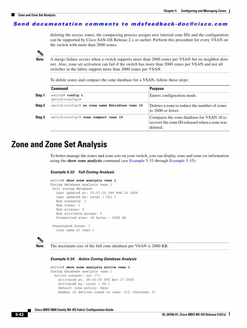
Send documenta t ion comments to mdsfeedback -doc@c i sco .com
Chapter 5 Configuring and Managing ZonesZone and Zone Set Analysis
deleting the excess zones, the compacting process assigns new internal zone IDs and the configuration can be supported by Cisco SAN-OS Release 2.x or earlier. Perform this procedure for every VSAN on the switch with more than 2000 zones.
Note A merge failure occurs when a switch supports more than 2000 zones per VSAN but its neighbor does not. Also, zone set activation can fail if the switch has more than 2000 zones per VSAN and not all switches in the fabric support more than 2000 zones per VSAN.
To delete zones and compact the zone database for a VSAN, follow these steps:
Zone and Zone Set AnalysisTo better manage the zones and zone sets on your switch, you can display zone and zone set information using the show zone analysis command (see Example 5-33 through Example 5-35).
Example 5-33 Full Zoning Analysis
switch# show zone analysis vsan 1Zoning database analysis vsan 1 Full zoning database Last updated at: 15:57:10 IST Feb 20 2006 Last updated by: Local [ CLI ] Num zonesets: 1 Num zones: 1 Num aliases: 0 Num attribute groups: 0 Formattted size: 36 bytes / 2048 Kb
Unassigned Zones: 1 zone name z1 vsan 1
Note The maximum size of the full zone database per VSAN is 2000 KB.
Example 5-34 Active Zoning Database Analysis
switch# show zone analysis active vsan 1Zoning database analysis vsan 1 Active zoneset: zs1 [*] Activated at: 08:03:35 UTC Nov 17 2005 Activated by: Local [ GS ] Default zone policy: Deny Number of devices zoned in vsan: 0/2 (Unzoned: 2)
Command Purpose
Step 1 switch# config t switch(config)#
Enters configuration mode.
Step 2 switch(config)# no zone name ExtraZone vsan 10 Deletes a zone to reduce the number of zones to 2000 or fewer.
Step 3 switch(config)# zone compact vsan 10 Compacts the zone database for VSAN 10 to recover the zone ID released when a zone was deleted.
5-42Cisco MDS 9000 Family NX-OS Fabric Configuration Guide
OL-20706-01, Cisco MDS NX-OS Release 5.0(1a)
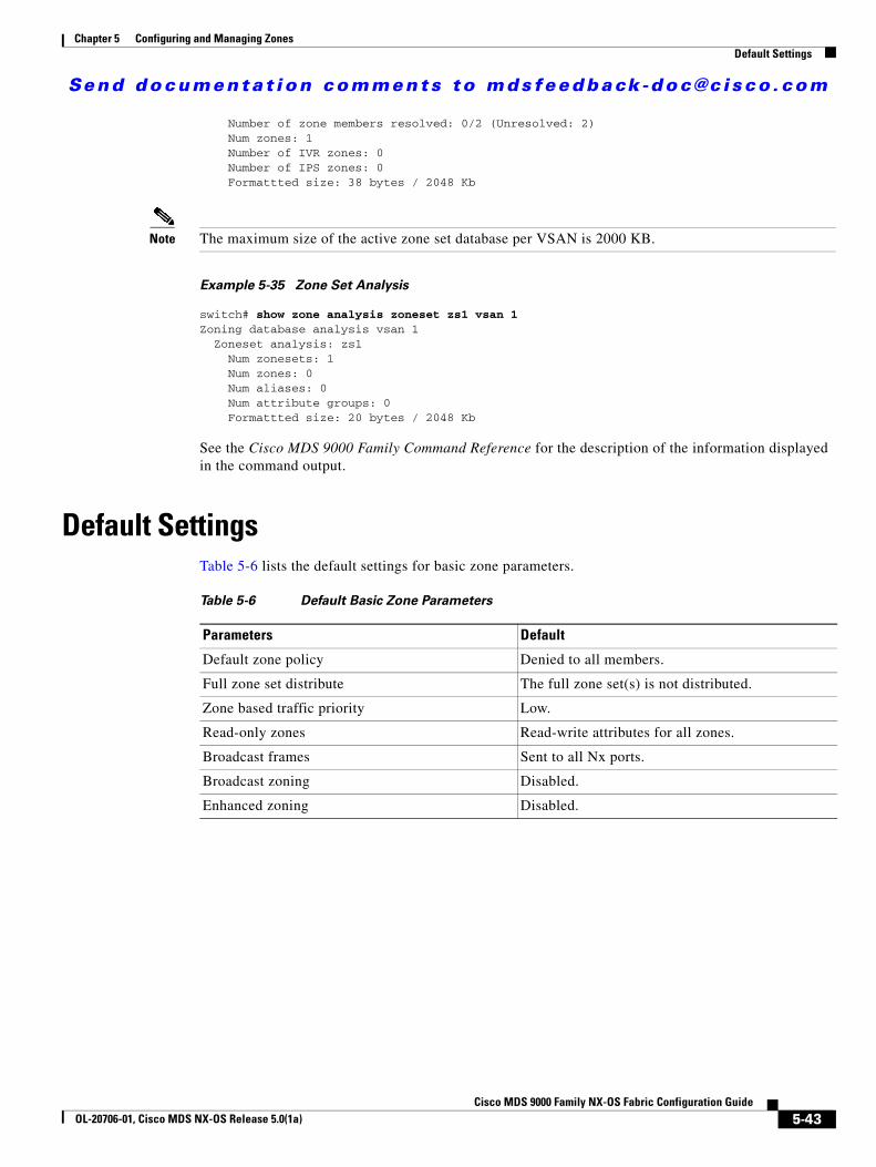
Send documenta t ion comments to mdsfeedback -doc@c i sco .com
Chapter 5 Configuring and Managing ZonesDefault Settings
Number of zone members resolved: 0/2 (Unresolved: 2) Num zones: 1 Number of IVR zones: 0 Number of IPS zones: 0 Formattted size: 38 bytes / 2048 Kb
Note The maximum size of the active zone set database per VSAN is 2000 KB.
Example 5-35 Zone Set Analysis
switch# show zone analysis zoneset zs1 vsan 1Zoning database analysis vsan 1 Zoneset analysis: zs1 Num zonesets: 1 Num zones: 0 Num aliases: 0 Num attribute groups: 0 Formattted size: 20 bytes / 2048 Kb
See the Cisco MDS 9000 Family Command Reference for the description of the information displayed in the command output.
Default Settings Table 5-6 lists the default settings for basic zone parameters.
Table 5-6 Default Basic Zone Parameters
Parameters Default
Default zone policy Denied to all members.
Full zone set distribute The full zone set(s) is not distributed.
Zone based traffic priority Low.
Read-only zones Read-write attributes for all zones.
Broadcast frames Sent to all Nx ports.
Broadcast zoning Disabled.
Enhanced zoning Disabled.
5-43Cisco MDS 9000 Family NX-OS Fabric Configuration Guide
OL-20706-01, Cisco MDS NX-OS Release 5.0(1a)

Send documenta t ion comments to mdsfeedback -doc@c i sco .com
Chapter 5 Configuring and Managing ZonesDefault Settings
5-44Cisco MDS 9000 Family NX-OS Fabric Configuration Guide
OL-20706-01, Cisco MDS NX-OS Release 5.0(1a)

Send documenta t ion comments to mdsfeedback -doc@c i sco .com
Cisco MOL-20706-01, Cisco MDS NX-OS Release 5.0(1a)
C H A P T E R 6
Distributing Device Alias ServicesAll switches in the Cisco MDS 9000 Family support Distributed Device Alias Services (device alias) on a per-VSAN basis and on a fabric-wide basis. Device alias distribution allows you to move host bus adapters (HBAs) between VSANs without manually reentering alias names.
This chapter includes the following sections:
• About Device Aliases, page 6-1
• About Device Alias Modes, page 6-1
• Device Alias Databases, page 6-4
• About Legacy Zone Alias Configuration Conversion, page 6-8
• Device Alias Statistics Cleanup, page 6-9
• Device Alias Configuration Verification, page 6-9
• Default Settings, page 6-12
About Device AliasesWhen the port WWN (pWWN) of a device must be specified to configure different features (zoning, QoS, port security) in a Cisco MDS 9000 Family switch, you must assign the correct device name each time you configure these features. An incorrect device name may cause unexpected results. You can avoid this problem if you define a user-friendly name for a port WWN and use this name in all of the configuration commands as required. These user-friendly names are referred to as device aliases in this chapter.
About Device Alias ModesDevice alias supports two modes: basic and enhanced mode.
• When device alias runs in the basic mode, all applications function like the applications on the 3.0 switches. When you configure the basic mode using device aliases, the application immediately expands to pWWNs. This operation continues until the mode is changed to enhanced.
• When device alias runs in the enhanced mode, all applications accept the device-alias configuration in the native format. The applications store the device alias name in the configuration and distribute it in the device alias format instead of expanding to pWWN. The applications track the device alias database changes and take actions to enforce it.
6-1DS 9000 Family NX-OS Fabric Configuration Guide

Send documenta t ion comments to mdsfeedback -doc@c i sco .com
Chapter 6 Distributing Device Alias ServicesAbout Device Alias Modes
A native device-alias configuration is not accepted in the interop mode VSAN. IVR zoneset activation will fail in interop mode VSANs if the corresponding twilight zones being injected are native device alias members.
Changing Mode SettingsWhen the device alias mode is changed from basic to enhanced mode, the applications are informed about the change. The applications start accepting the device alias-based configuration in the native format.
Note Because the device alias was previously running in the basic mode, the applications do not have any prior native device alias configuration.
The applications check for an exisiting device alias cofiguration in the native format. If the device alias is in the native format, the applications reject the request and device alias mode cannot be changed to basic.
All native device alias configurations (both on local and remote switches) must be explicitly removed, or all device alias members must be replaced with the corresponding pWWN before changing the mode back to basic.
The process can be automated using the force option. Use the no device-alias mode enhanced force command to enable applications to automatically replace all device alias members with the corresponding pWWNs. If a device alias member does not have a corresponding pWWN mapping in the device alias database, the configuration will be removed.
Device Alias Mode DistributionIf the device alias distribution is turned on, it is distributed to the other switches in the network whenever there is a change in the mode. You cannot change the mode from basic to enhanced unless all the switches are upgraded to Release 3.1. The device alias enhancements will not apply unless the entire fabric is upgraded to Release 3.1.
Note When all the switches are upgraded to Release 3.1, you cannot automatically convert to enhanced mode. You do not need to change to enhanced mode, you can continue working in the basic mode.
Merging Device AliasIf two fabrics are running different device alias modes and are joined together, the device alias merge will fail. There is no automatic conversion of one mode to the other during the merge process. You will need to resolve the issue.
Note Release 3.0 switches run in basic mode.
At the application level, a merger takes place between the applications and the fabric. For example, zone merge occurs when the E port is up and the IVR/PSM/DPVM merge occurs due to CFS. This merge is completely independent of the device alias merge.
6-2Cisco MDS 9000 Family NX-OS Fabric Configuration Guide
OL-20706-01, Cisco MDS NX-OS Release 5.0(1a)

Send documenta t ion comments to mdsfeedback -doc@c i sco .com
Chapter 6 Distributing Device Alias ServicesAbout Device Alias Modes
If the application running on an enhanced fabric has a native device alias configuration, the application must fail the merge. The application has to fail the merge even though the other fabric is can support the native device alias-based configuration, but is running in the basic mode. You will need to resolve the issue. Once the device alias merge issue is resolved, each application must be fixed accordingly.
Resolving Merge and Device Alias Mode MismatchIf two fabrics are running in different modes and the device alias merge fails between the fabrics, the conflict can be resolved by selecting one mode or the other. If you choose the enhanced mode, ensure that all the switches are running at least the Release 3.1 version. Otherwise, the enhanced mode cannot be turned on. If you choose the basic mode, the applications running on the enhanced fabric have to comply with the device alias merge.
The device alias merge fails because of mode mismatch, but the application merge succeeds if it does not have any native device alias configurations.
If the native device alias configuration is attempted on an application from a Release 3.1 switch, the commit must be rejected because of device alias mode mismatch on some of the applications.
Note The applications should not accept any native device alias configuration over SNMP if the device alias is running in the basic mode on that particular switch.
Note Confcheck will be added when the enhanced mode is turned on and removed when it is turned off. Applications have to add confcheck if they have a device alias configuration in the native format. They have to remove confcheck once the configuration is removed.
Device Alias FeaturesDevice aliases have the following features:
• The device alias information is independent of your VSAN configuration.
• The device alias configuration and distribution is independent of the zone server and the zone server database.
• You can import legacy zone alias configurations without losing data.
• The device alias application uses the Cisco Fabric Services (CFS) infrastructure to enable efficient database management and distribution. Device aliases use the coordinated distribution mode and the fabric-wide distribution scope (refer to the Cisco MDS 9000 Family NX-OS System Management Configuration Guide).
• When you configure zones, IVR zones, or QoS features using device aliases, and if you display these configurations, you will automatically see that the device aliases are displayed along with their respective pWWNs.
Device Alias RequirementsDevice aliases have the following requirements:
• You can only assign device aliases to pWWNs.
6-3Cisco MDS 9000 Family NX-OS Fabric Configuration Guide
OL-20706-01, Cisco MDS NX-OS Release 5.0(1a)

Send documenta t ion comments to mdsfeedback -doc@c i sco .com
Chapter 6 Distributing Device Alias ServicesDevice Alias Databases
• The mapping between the pWWN and the device alias to which it is mapped must have a one-to-one relationship. A pWWN can be mapped to only one device alias and vice versa.
• A device alias name is restricted to 64 alphanumeric characters and may include one or more of the following characters:
– a to z and A to Z
– 1 to 9
– - (hyphen) and _ (underscore)
– $ (dollar sign) and ^ (up caret)
Zone Aliases Versus Device AliasesTable 6-1 compares the configuration differences between zone-based alias configuration and device alias configuration.
Device Alias DatabasesThe device alias feature uses two databases to accept and implement device alias configurations.
• Effective database—The database currently used by the fabric.
• Pending database—Your subsequent device alias configuration changes are stored in the pending database.
If you modify the device alias configuration, you need to commit or discard the changes as the fabric remains locked during this period.
This section includes the following sections:
• Creating Device Aliases, page 6-5
• About Device Alias Distribution, page 6-5
• Committing Changes, page 6-6
• Discarding Changes, page 6-6
• About Legacy Zone Alias Configuration Conversion, page 6-8
Table 6-1 Comparison Between Zone Aliases and Device Aliases
Zone-Based Aliases Device Aliases
Aliases are limited to the specified VSAN. You can define device aliases without specifying the VSAN number. You can also use the same definition in one or more VSANs without any restrictions.
Zone aliases are part of the zoning configuration. The alias mapping cannot be used to configure other features.
Device aliases can be used with any feature that uses the pWWN.
You can use any zone member type to specify the end devices.
Only pWWNs are supported along with new device aliases such as IP addresses.
Configuration is contained within the Zone Server database and is not available to other features.
Device aliases are not restricted to zoning. Device alias configuration is available to the FCNS, zone, fcping, traceroute, and IVR applications.
6-4Cisco MDS 9000 Family NX-OS Fabric Configuration Guide
OL-20706-01, Cisco MDS NX-OS Release 5.0(1a)

Send documenta t ion comments to mdsfeedback -doc@c i sco .com
Chapter 6 Distributing Device Alias ServicesDevice Alias Databases
• Disabling and Enabling Device Alias Distribution, page 6-7
Creating Device AliasesTo a create a device alias in the pending database, follow these steps:
To display the device alias configuration, use the show device-alias name command.
switch# show device-alias name xdevice-alias name x pwwn 21:01:00:e0:8b:2e:80:93
About Device Alias DistributionBy default, device alias distribution is enabled. The device alias feature uses the coordinated distribution mechanism to distribute the modifications to all switches in a fabric.
If you have not committed the changes and you disable distribution, then a commit task will fail.
Example 6-1 Displays a Failed Status
switch# show device-alias statusFabric Distribution: DisabledDatabase:- Device Aliases 25Status of the last CFS operation issued from this switch:==========================================================Operation: CommitStatus: Failed (Reason: Operation is not permitted as the fabric distribution is currently disabled.)
Command Purpose
Step 1 switch# config t switch(config)#
Enters configuration mode.
Step 2 switch(config)# device-alias databaseswitch(config-device-alias-db)#
Enters the pending database configuration submode.
Step 3 switch(config-device-alias-db)# device-alias name Device1 pwwn 21:01:00:e0:8b:2e:80:93
Specifies a device name (Device1) for the device that is identified by its pWWN. Starts writing to the pending database and simultaneously locks the fabric as this is the first-issued device alias configuration command.
switch(config-device-alias-db)# no device-alias name Device1
Removes the device name (Device1) for the device that is identified by its pWWN.
switch(config-device-alias-db)# device-alias rename Device1 Device2
Renames an existing device alias (Device1) with a new name (Device2).
6-5Cisco MDS 9000 Family NX-OS Fabric Configuration Guide
OL-20706-01, Cisco MDS NX-OS Release 5.0(1a)
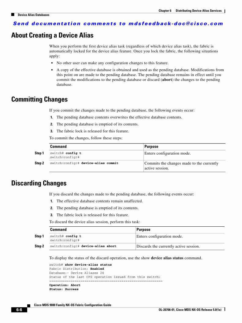
Send documenta t ion comments to mdsfeedback -doc@c i sco .com
Chapter 6 Distributing Device Alias ServicesDevice Alias Databases
About Creating a Device AliasWhen you perform the first device alias task (regardless of which device alias task), the fabric is automatically locked for the device alias feature. Once you lock the fabric, the following situations apply:
• No other user can make any configuration changes to this feature.
• A copy of the effective database is obtained and used as the pending database. Modifications from this point on are made to the pending database. The pending database remains in effect until you commit the modifications to the pending database or discard (abort) the changes to the pending database.
Committing ChangesIf you commit the changes made to the pending database, the following events occur:
1. The pending database contents overwrites the effective database contents.
2. The pending database is emptied of its contents.
3. The fabric lock is released for this feature.
To commit the changes, follow these steps:
Discarding ChangesIf you discard the changes made to the pending database, the following events occur:
1. The effective database contents remain unaffected.
2. The pending database is emptied of its contents.
3. The fabric lock is released for this feature.
To discard the device alias session, perform this task:
To display the status of the discard operation, use the show device alias status command.
switch# show device-alias statusFabric Distribution: EnabledDatabase:- Device Aliases 24Status of the last CFS operation issued from this switch:==========================================================Operation: AbortStatus: Success
Command Purpose
Step 1 switch# config t switch(config)#
Enters configuration mode.
Step 2 switch(config)# device-alias commit Commits the changes made to the currently active session.
Command Purpose
Step 1 switch# config t switch(config)#
Enters configuration mode.
Step 2 switch(config)# device-alias abort Discards the currently active session.
6-6Cisco MDS 9000 Family NX-OS Fabric Configuration Guide
OL-20706-01, Cisco MDS NX-OS Release 5.0(1a)

Send documenta t ion comments to mdsfeedback -doc@c i sco .com
Chapter 6 Distributing Device Alias ServicesDevice Alias Databases
Fabric Lock OverrideIf you have performed a device alias task and have forgotten to release the lock by either committing or discarding the changes, an administrator can release the lock from any switch in the fabric. If the administrator performs this task, your changes to the pending database are discarded and the fabric lock is released.
Tip The changes are only available in the volatile directory and are subject to being discarded if the switch is restarted.
To use administrative privileges and release a locked device alias session, use the clear device-name session command in EXEC mode.
switch# clear device-alias session
To display the status of the clear operation, use the show device-alias status command.
switch# show device-alias statusFabric Distribution: EnabledDatabase:- Device Aliases 24Status of the last CFS operation issued from this switch:==========================================================Operation: Clear Session <--------------------Lock released by administratorStatus: Success <---------------------------------Successful status of the operation
Disabling and Enabling Device Alias DistributionTo disable or enable the device alias distribution, follow these steps:
To display the status of device alias distribution, use the show device-alias status command (see Example 6-2 and Example 6-3).
Example 6-2 Displays Device Alias Status When Distribution Is Enabled
switch# show device-alias statusFabric Distribution: Enabled <-------------------------------Distribution is enabledDatabase:-Device Aliases 24Locked By:-User “Test” SWWN 20:00:00:0c:cf:f4:02:83<-Lock holder’s user name and switch IDPending Database:- Device Aliases 24Status of the last CFS operation issued from this switch:==========================================================Operation: Enable Fabric DistributionStatus: Success
Command Purpose
Step 1 switch# config t switch(config)#
Enters configuration mode.
Step 2 switch(config)# no device-alias distribute Disables the distribution.
switch(config)# device-alias distribute Enables the distribution (default).
6-7Cisco MDS 9000 Family NX-OS Fabric Configuration Guide
OL-20706-01, Cisco MDS NX-OS Release 5.0(1a)

Send documenta t ion comments to mdsfeedback -doc@c i sco .com
Chapter 6 Distributing Device Alias ServicesAbout Legacy Zone Alias Configuration Conversion
Example 6-3 Displays Device Alias Status When Distribution Is Disabled
switch# show device-alias statusFabric Distribution: DisabledDatabase:- Device Aliases 24Status of the last CFS operation issued from this switch:==========================================================Operation: Disable Fabric DistributionStatus: Success
About Legacy Zone Alias Configuration ConversionYou can import legacy zone alias configurations to use this feature without losing data, if they satisfy the following restrictions:
• Each zone alias has only one member.
• The member type is pWWN.
• The name and definition of the zone alias should not be the same as any existing device alias name.
If any name conflict exists, the zone aliases are not imported.
Tip Ensure to copy any required zone aliases to the device alias database as required by your configuration.
When an import operation is complete, the modified alias database is distributed to all other switches in the physical fabric when you perform the commit operation. At this time if you do not want to distribute the configuration to other switches in the fabric, you can perform the abort operation and the merge changes are completely discarded.
This section includes the following topics:
• Importing a Zone Alias, page 6-8
• Device Alias Statistics Cleanup, page 6-9
Importing a Zone AliasTo import the zone alias for a specific VSAN, follow these steps:
To display device alias information in zone sets, use the show zoneset command (see Example 6-4 and Example 6-5).
Example 6-4 Displays the Device Aliases in the Zone Set Information
switch# show zonesetzoneset name s1 vsan 1 zone name z1 vsan 1
Command Purpose
Step 1 switch# config t switch(config)#
Enters configuration mode.
Step 2 switch(config)# device-alias import fcalias vsan 3
Imports the fcalias information for the specified VSAN.
6-8Cisco MDS 9000 Family NX-OS Fabric Configuration Guide
OL-20706-01, Cisco MDS NX-OS Release 5.0(1a)

Send documenta t ion comments to mdsfeedback -doc@c i sco .com
Chapter 6 Distributing Device Alias ServicesDatabase Merge Guidelines
pwwn 21:01:00:e0:8b:2e:80:93 [x] <---------------Device alias displayed for each pWWN. pwwn 21:00:00:20:37:39:ab:5f [y]zone name z2 vsan 1 pwwn 21:00:00:e0:8b:0b:66:56 [SampleName] pwwn 21:00:00:20:37:39:ac:0d [z]
Example 6-5 Displays the Device Aliases in the Active Zone Set
switch# show zoneset activezoneset name s1 vsan 1 zone name z1 vsan 1 * fcid 0x670100 [pwwn 21:01:00:e0:8b:2e:80:93] [x] pwwn 21:00:00:20:37:39:ab:5f [y]
zone name z2 vsan 1 * fcid 0x670200 [pwwn 21:00:00:e0:8b:0b:66:56] [SampleName] pwwn 21:00:00:20:37:39:ac:0d [z]
Device Alias Statistics CleanupUse the clear device-name statistics command to clear device alias statistics (for debugging purposes):
switch# clear device-alias statistics
Database Merge GuidelinesFor information about CFS merge support, refer to the Cisco MDS 9000 Family NX-OS System Management Configuration Guide for detailed concepts.
When merging two device alias databases, follow these guidelines:
• Verify that two device aliases with different names are not mapped to the same pWWN.
• Verify that two different pWWNs are not mapped to the same device aliases
• Verify that the combined number of the device aliases in both databases does not exceed 8191 (8K). For example, if database N has 6000 device aliases and database M has 2192 device aliases, this merge operation will fail.
Device Alias Configuration VerificationYou can view device alias information by using the show device-alias command. See Examples 6-6 to 6-17.
Example 6-6 Displays All Configured Device Aliases from the Effective Database
switch# show device-alias databasedevice-alias name SampleName pwwn 21:00:00:e0:8b:0b:66:56device-alias name x pwwn 21:01:00:e0:8b:2e:80:93
Total number of entries = 2
6-9Cisco MDS 9000 Family NX-OS Fabric Configuration Guide
OL-20706-01, Cisco MDS NX-OS Release 5.0(1a)

Send documenta t ion comments to mdsfeedback -doc@c i sco .com
Chapter 6 Distributing Device Alias ServicesDevice Alias Configuration Verification
Example 6-7 Displays the Pending Database with No Modifications
switch# show device-alias database pendingThere are no pending changes
Example 6-8 Displays the Pending Database with Modifications
switch# show device-alias database pendingdevice-alias name x pwwn 21:01:00:e0:8b:2e:80:93device-alias name SampleName pwwn 21:00:00:e0:8b:0b:66:56device-alias name y pwwn 21:00:00:20:37:39:ab:5fdevice-alias name z pwwn 21:00:00:20:37:39:ac:0d
Total number of entries = 4
Example 6-9 Displays the Specified Device Name in the Pending Database
switch# show device-alias name x pendingdevice-alias name x pwwn 21:01:00:e0:8b:2e:80:93
Example 6-10 Displays the Specified pWWN in the Pending Database
switch# show device-alias pwwn 21:01:00:e0:8b:2e:80:93 pendingdevice-alias name x pwwn 21:01:00:e0:8b:2e:80:93
Example 6-11 Displays the Difference Between the Pending and Effective Databases
switch# show device-alias database pending-diff- device-alias name Doc pwwn 21:01:02:03:00:01:01:01+ device-alias name SampleName pwwn 21:00:00:e0:8b:0b:66:56
Example 6-12 Displays the Specified pWWN
switch# show device-alias pwwn 21:01:01:01:01:11:01:01 device-alias name Doc pwwn 21:01:01:01:01:11:01:01
Example 6-13 Displays the Device Alias in the FLOGI Database
switch# show flogi database---------------------------------------------------------------------------INTERFACE VSAN FCID PORT NAME NODE NAME---------------------------------------------------------------------------fc2/9 1 0x670100 21:01:00:e0:8b:2e:80:93 20:01:00:e0:8b:2e:80:93 [x] <---------------------------------------------Device alias namefc2/12 1 0x670200 21:00:00:e0:8b:0b:66:56 20:00:00:e0:8b:0b:66:56 [SampleName] <---------------------------------Device alias name
Total number of flogi = 2
6-10Cisco MDS 9000 Family NX-OS Fabric Configuration Guide
OL-20706-01, Cisco MDS NX-OS Release 5.0(1a)

Send documenta t ion comments to mdsfeedback -doc@c i sco .com
Chapter 6 Distributing Device Alias ServicesDevice Alias Configuration Verification
Example 6-14 Displays the Device Alias in the FCNS Database
switch# show fcns database
VSAN 1:--------------------------------------------------------------------------FCID TYPE PWWN (VENDOR) FC4-TYPE:FEATURE--------------------------------------------------------------------------0x670100 N 21:01:00:e0:8b:2e:80:93 (Qlogic) scsi-fcp:init [x]0x670200 N 21:00:00:e0:8b:0b:66:56 (Qlogic) scsi-fcp:init [SampleName]
Total number of entries = 2
Example 6-15 Displays the fcping Statistics for the Specified Device Alias
switch# fcping device-alias x vsan 128 bytes from 21:01:00:e0:8b:2e:80:93 time = 358 usec28 bytes from 21:01:00:e0:8b:2e:80:93 time = 226 usec28 bytes from 21:01:00:e0:8b:2e:80:93 time = 372 usec
Example 6-16 Displays the fctrace Information for the Specified Device Alias
switch# fctrace device-alias x vsan 1Route present for : 21:01:00:e0:8b:2e:80:9320:00:00:05:30:00:4a:e2(0xfffc67)
Where available, device aliases are displayed regardless of a member being configured using a device-alias command or a zone-specific member pwwn command (see Example 6-4 and Example 6-5).
Example 6-17 Displays Statistics for the Device Alias Application
switch# show device-alias statistics Device Alias Statistics===========================================Lock requests sent: 2Database update requests sent: 1Unlock requests sent: 1Lock requests received: 1Database update requests received: 1Unlock requests received: 1Lock rejects sent: 0Database update rejects sent: 0Unlock rejects sent: 0Lock rejects received: 0Database update rejects received: 0Unlock rejects received: 0Merge requests received: 0Merge request rejects sent: 0Merge responses received: 2Merge response rejects sent: 0Activation requests received: 0Activation request rejects sent: 0Activation requests sent: 2Activation request rejects received: 0
6-11Cisco MDS 9000 Family NX-OS Fabric Configuration Guide
OL-20706-01, Cisco MDS NX-OS Release 5.0(1a)

Send documenta t ion comments to mdsfeedback -doc@c i sco .com
Chapter 6 Distributing Device Alias ServicesDefault Settings
Default Settings Table 6-2 lists the default settings for device alias parameters.
Table 6-2 Default Device Alias Parameters
Parameters Default
Database in use Effective database.
Database to accept changes Pending database.
Device alias fabric lock state Locked with the first device alias task.
6-12Cisco MDS 9000 Family NX-OS Fabric Configuration Guide
OL-20706-01, Cisco MDS NX-OS Release 5.0(1a)
Send documenta t ion comments to mdsfeedback -doc@c i sco .com
Cisco MOL-20706-01, Cisco MDS NX-OS Release 5.0(1a)
C H A P T E R 7
Configuring Fibre Channel Routing Services and ProtocolsFabric Shortest Path First (FSPF) is the standard path selection protocol used by Fibre Channel fabrics. The FSPF feature is enabled by default on all Fibre Channel switches. Except in configurations that require special consideration, you do not need to configure any FSPF services. FSPF automatically calculates the best path between any two switches in a fabric. Specifically, FSPF is used to:
• Dynamically compute routes throughout a fabric by establishing the shortest and quickest path between any two switches.
• Select an alternative path in the event of the failure of a given path. FSPF supports multiple paths and automatically computes an alternative path around a failed link. It provides a preferred route when two equal paths are available.
This chapter provides details on Fibre Channel routing services and protocols. It includes the following sections:
• About FSPF, page 7-2
• FSPF Global Configuration, page 7-4
• FSPF Interface Configuration, page 7-6
• FSPF Routes, page 7-9
• In-Order Delivery, page 7-13
• Flow Statistics Configuration, page 7-17
• Default Settings, page 7-21
7-1DS 9000 Family NX-OS Fabric Configuration Guide

Send documenta t ion comments to mdsfeedback -doc@c i sco .com
Chapter 7 Configuring Fibre Channel Routing Services and ProtocolsAbout FSPF
About FSPFFSPF is the protocol currently standardized by the T11 committee for routing in Fibre Channel networks. The FSPF protocol has the following characteristics and features:
• Supports multipath routing.
• Bases path status on a link state protocol.
• Routes hop by hop, based only on the domain ID.
• Runs only on E ports or TE ports and provides a loop free topology.
• Runs on a per VSAN basis. Connectivity in a given VSAN in a fabric is guaranteed only for the switches configured in that VSAN.
• Uses a topology database to keep track of the state of the links on all switches in the fabric and associates a cost with each link.
• Guarantees a fast reconvergence time in case of a topology change. Uses the standard Dijkstra algorithm, but there is a static dynamic option for a more robust, efficient, and incremental Dijkstra algorithm. The reconvergence time is fast and efficient as the route computation is done on a per VSAN basis.
FSPF ExamplesThis section provides examples of topologies and applications that demonstrate the benefits of FSPF.
Note The FSPF feature can be used on any topology.
Fault Tolerant Fabric
Figure 7-1 depicts a fault tolerant fabric using a partial mesh topology. If a link goes down anywhere in the fabric, any switch can still communicate with all others in the fabric. In the same way, if any switch goes down, the connectivity of the rest of the fabric is preserved.
Figure 7-1 Fault Tolerant Fabric
For example, if all links are of equal speed, the FSPF calculates two equal paths from A to C: A-D-C (green) and A-E-C (blue).
7954
1
A B
D E
C
7-2Cisco MDS 9000 Family NX-OS Fabric Configuration Guide
OL-20706-01, Cisco MDS NX-OS Release 5.0(1a)

Send documenta t ion comments to mdsfeedback -doc@c i sco .com
Chapter 7 Configuring Fibre Channel Routing Services and ProtocolsAbout FSPF
Redundant Links
To further improve on the topology in Figure 7-1, each connection between any pair of switches can be replicated; two or more links can be present between a pair of switches. Figure 7-2 shows this arrangement. Because switches in the Cisco MDS 9000 Family support PortChanneling, each pair of physical links can appear to the FSPF protocol as one single logical link.
By bundling pairs of physical links, FSPF efficiency is considerably improved by the reduced database size and the frequency of link updates. Once physical links are aggregated, failures are not attached to a single link but to the entire PortChannel. This configuration also improves the resiliency of the network. The failure of a link in a PortChannel does not trigger a route change, thereby reducing the risks of routing loops, traffic loss, or fabric downtime for route reconfiguration.
Figure 7-2 Fault Tolerant Fabric with Redundant Links
For example, if all links are of equal speed and no PortChannels exist, the FSPF calculates four equal paths from A to C: A1-E-C, A2-E-C, A3-D-C, and A4-D-C. If PortChannels exist, these paths are reduced to two.
Failover Scenarios for PortChannels and FSPF Links
The SmartBits traffic generator was used to evaluate the scenarios displayed in Figure 7-3. Two links between switch 1 and switch 2 exist as either equal-cost ISLs or PortChannels. There is one flow from traffic generator 1 to traffic generator 2. The traffic was tested at 100 percent utilization at 1 Gbps in two scenarios:
• Disabling the traffic link by physically removing the cable (see Table 7-1).
• Shutting down either switch 1 or switch 2 (see Table 7-2).
Figure 7-3 Failover Scenario Using Traffic Generators
7954
2
A B C
ED
12
34
Table 7-1 Physically Removing the Cable for the SmartBits Scenario
PortChannel Scenario FSPF Scenario (Equal cost ISL)
Switch 1 Switch 2 Switch 1 Switch 2
110 msec (~2K frame drops) 130+ msec (~4k frame drops)
100 msec (hold time when a signal loss is reported as mandated by the standard)
Traffic Generator 1 Traffic Generator 2
Switch 1 Switch 2
9927
8
7-3Cisco MDS 9000 Family NX-OS Fabric Configuration Guide
OL-20706-01, Cisco MDS NX-OS Release 5.0(1a)
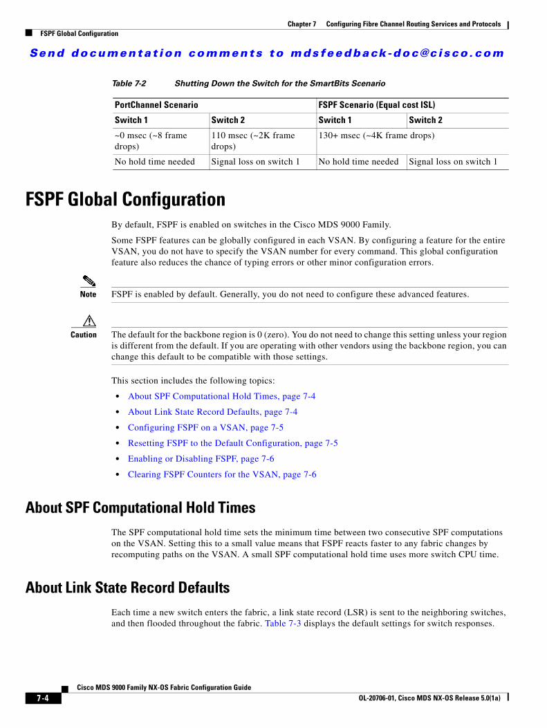
Send documenta t ion comments to mdsfeedback -doc@c i sco .com
Chapter 7 Configuring Fibre Channel Routing Services and ProtocolsFSPF Global Configuration
FSPF Global ConfigurationBy default, FSPF is enabled on switches in the Cisco MDS 9000 Family.
Some FSPF features can be globally configured in each VSAN. By configuring a feature for the entire VSAN, you do not have to specify the VSAN number for every command. This global configuration feature also reduces the chance of typing errors or other minor configuration errors.
Note FSPF is enabled by default. Generally, you do not need to configure these advanced features.
Caution The default for the backbone region is 0 (zero). You do not need to change this setting unless your region is different from the default. If you are operating with other vendors using the backbone region, you can change this default to be compatible with those settings.
This section includes the following topics:
• About SPF Computational Hold Times, page 7-4
• About Link State Record Defaults, page 7-4
• Configuring FSPF on a VSAN, page 7-5
• Resetting FSPF to the Default Configuration, page 7-5
• Enabling or Disabling FSPF, page 7-6
• Clearing FSPF Counters for the VSAN, page 7-6
About SPF Computational Hold TimesThe SPF computational hold time sets the minimum time between two consecutive SPF computations on the VSAN. Setting this to a small value means that FSPF reacts faster to any fabric changes by recomputing paths on the VSAN. A small SPF computational hold time uses more switch CPU time.
About Link State Record DefaultsEach time a new switch enters the fabric, a link state record (LSR) is sent to the neighboring switches, and then flooded throughout the fabric. Table 7-3 displays the default settings for switch responses.
Table 7-2 Shutting Down the Switch for the SmartBits Scenario
PortChannel Scenario FSPF Scenario (Equal cost ISL)
Switch 1 Switch 2 Switch 1 Switch 2
~0 msec (~8 frame drops)
110 msec (~2K frame drops)
130+ msec (~4K frame drops)
No hold time needed Signal loss on switch 1 No hold time needed Signal loss on switch 1
7 -4Cisco MDS 9000 Family NX-OS Fabric Configuration Guide
OL-20706-01, Cisco MDS NX-OS Release 5.0(1a)

Send documenta t ion comments to mdsfeedback -doc@c i sco .com
Chapter 7 Configuring Fibre Channel Routing Services and ProtocolsFSPF Global Configuration
The LSR minimum arrival time is the period between receiving LSR updates on this VSAN. Any LSR updates that arrive before the LSR minimum arrival time are discarded.
The LSR minimum interval time is the frequency at which this switch sends LSR updates on a VSAN.
Configuring FSPF on a VSANTo configure an FSPF feature for the entire VSAN, follow these steps:
Resetting FSPF to the Default ConfigurationTo return the FSPF VSAN global configuration to its factory default, follow these steps:
Table 7-3 LSR Default Settings
LSR Option Default Description
Acknowledgment interval (RxmtInterval)
5 seconds The time a switch waits for an acknowledgment from the LSR before retransmission.
Refresh time (LSRefreshTime)
30 minutes The time a switch waits before sending an LSR refresh transmission.
Maximum age (MaxAge) 60 minutes The time a switch waits before dropping the LSR from the database.
Command Purpose
Step 1 switch# config tswitch(config)#
Enters configuration mode.
Step 2 switch(config)# fspf config vsan 1 Enters FSPF global configuration mode for the specified VSAN.
Step 3 switch-config-(fspf-config)# spf static Forces static SPF computation for the dynamic (default) incremental VSAN.
Step 4 switch-config-(fspf-config)# spf hold-time 10 Configures the hold time between two route computations in milliseconds (msec) for the entire VSAN. The default value is 0.
Note If the specified time is shorter, the routing is faster. However, the processor consumption increases accordingly.
Step 5 switch-config-(fspf-config)# region 7 Configures the autonomous region for this VSAN and specifies the region ID (7).
Command Purpose
Step 1 switch# config tswitch(config)#
Enters configuration mode.
Step 2 switch(config)# no fspf config vsan 3 Deletes the FSPF configuration for VSAN 3.
7-5Cisco MDS 9000 Family NX-OS Fabric Configuration Guide
OL-20706-01, Cisco MDS NX-OS Release 5.0(1a)

Send documenta t ion comments to mdsfeedback -doc@c i sco .com
Chapter 7 Configuring Fibre Channel Routing Services and ProtocolsFSPF Interface Configuration
Enabling or Disabling FSPFTo enable or disable FSPF routing protocols, follow these steps:
Clearing FSPF Counters for the VSANTo clear the FSPF statistics counters for the entire VSAN, follow this step:
FSPF Interface ConfigurationSeveral FSPF commands are available on a per-interface basis. These configuration procedures apply to an interface in a specific VSAN.
This section includes the following topics:
• About FSPF Link Cost, page 7-6
• Configuring FSPF Link Cost, page 7-7
• About Hello Time Intervals, page 7-7
• Configuring Hello Time Intervals, page 7-7
• About Dead Time Intervals, page 7-7
• Configuring Dead Time Intervals, page 7-8
• About Retransmitting Intervals, page 7-8
• Configuring Retransmitting Intervals, page 7-8
• About Disabling FSPF for Specific Interfaces, page 7-8
• Disabling FSPF for Specific Interfaces, page 7-9
• Clearing FSPF Counters for an Interface, page 7-9
About FSPF Link CostFSPF tracks the state of links on all switches in the fabric, associates a cost with each link in its database, and then chooses the path with a minimal cost. The cost associated with an interface can be administratively changed to implement the FSPF route selection. The integer value to specify cost can range from 1 to 65,535. The default cost for 1 Gbps is 1000 and for 2 Gbps is 500.
Command Purpose
Step 1 switch# config tswitch(config)#
Enters configuration mode.
Step 2 switch(config)# fspf enable vsan 7 Enables the FSPF routing protocol in VSAN 7.
switch(config)# no fspf enable vsan 5 Disables the FSPF routing protocol in VSAN 5.
Command Purpose
Step 1 switch# clear fspf counters vsan 1 Clears the FSPF statistics counters for the specified VSAN. If an interface reference is not specified, all counters are cleared.
7-6Cisco MDS 9000 Family NX-OS Fabric Configuration Guide
OL-20706-01, Cisco MDS NX-OS Release 5.0(1a)

Send documenta t ion comments to mdsfeedback -doc@c i sco .com
Chapter 7 Configuring Fibre Channel Routing Services and ProtocolsFSPF Interface Configuration
Configuring FSPF Link CostTo configure FSPF link cost, follow these steps:
About Hello Time IntervalsYou can set the FSPF Hello time interval to specify the interval between the periodic hello messages sent to verify the health of the link. The integer value can range from 1 to 65,535 seconds.
Note This value must be the same in the ports at both ends of the ISL.
Configuring Hello Time IntervalsTo configure the FSPF Hello time interval, follow these steps:
About Dead Time IntervalsYou can set the FSPF dead time interval to specify the maximum interval for which a hello message must be received before the neighbor is considered lost and removed from the database. The integer value can range from 1 to 65,535 seconds.
Note This value must be the same in the ports at both ends of the ISL.
Command Purpose
Step 1 switch# config tswitch(config)#
Enters configuration mode.
Step 2 switch(config)# interface fc1/4switch(config-if)#
Configures the specified interface, or if already configured, enters configuration mode for the specified interface.
Step 3 switch(config-if)# fspf cost 5 vsan 90 Configures the cost for the selected interface in VSAN 90.
Command Purpose
Step 1 switch# config tswitch(config)#
Enters configuration mode.
Step 2 switch(config)# interface fc1/4switch(config-if)#
Configures the specified interface, or if already configured, enters configuration mode for the specified interface.
Step 3 switch(config-if)# fspf hello-interval 15 vsan 175switch(config-if)#
Specifies the hello message interval (15 seconds) to verify the health of the link in VSAN 175. The default is 20 seconds.
7-7Cisco MDS 9000 Family NX-OS Fabric Configuration Guide
OL-20706-01, Cisco MDS NX-OS Release 5.0(1a)

Send documenta t ion comments to mdsfeedback -doc@c i sco .com
Chapter 7 Configuring Fibre Channel Routing Services and ProtocolsFSPF Interface Configuration
Caution An error is reported at the command prompt if the configured dead time interval is less than the hello time interval.
Configuring Dead Time IntervalsTo configure the FSPF dead time interval, follow these steps:
About Retransmitting IntervalsYou can specify the time after which an unacknowledged link state update should be transmitted on the interface. The integer value to specify retransmit intervals can range from 1 to 65,535 seconds.
Note This value must be the same on the switches on both ends of the interface.
Configuring Retransmitting IntervalsTo configure the FSPF retransmit time interval, follow these steps:
About Disabling FSPF for Specific InterfacesYou can disable the FSPF protocol for selected interfaces. By default, FSPF is enabled on all E ports and TE ports. This default can be disabled by setting the interface as passive.
Command Purpose
Step 1 switch# config tswitch(config)#
Enters configuration mode.
Step 2 switch(config)# interface fc1/4switch(config-if)#
Configures the specified interface, or if already configured, enters configuration mode for the specified interface.
Step 3 switch(config-if)# fspf dead-interval 25 vsan 7switch(config-if)#
Specifies the maximum interval for VSAN 7 before which a hello message must be received on the selected interface before the neighbor is considered lost. The default is 80 seconds.
Command Purpose
Step 1 switch# config tswitch(config)#
Enters configuration mode.
Step 2 switch(config)# interface fc1/4switch(config-if)#
Configures the specified interface, or if already configured, enters configuration mode for the specified interface.
Step 3 switch(config-if)# fspf retransmit-interval 15 vsan 12switch(config-if)#
Specifies the retransmit time interval for unacknowledged link state updates in VSAN 12. The default is 5 seconds.
7-8Cisco MDS 9000 Family NX-OS Fabric Configuration Guide
OL-20706-01, Cisco MDS NX-OS Release 5.0(1a)

Send documenta t ion comments to mdsfeedback -doc@c i sco .com
Chapter 7 Configuring Fibre Channel Routing Services and ProtocolsFSPF Routes
Note FSPF must be enabled at both ends of the interface for the protocol to work.
Disabling FSPF for Specific InterfacesYou can disable the FSPF protocol for selected interfaces. By default, FSPF is enabled on all E ports and TE ports. This default can be disabled by setting the interface as passive.
To disable FSPF for a specific interface, follow these steps:
You can disable the FSPF protocol for selected interfaces. By default, FSPF is enabled on all E ports and TE ports. This default can be disabled by setting the interface as passive.
Clearing FSPF Counters for an InterfaceTo clear the FSPF statistics counters for an interface, follow this step:
FSPF RoutesFSPF routes traffic across the fabric, based on entries in the FSPF database. These routes can be learned dynamically, or configured statically.
This section includes the following topics:
• About Fibre Channel Routes, page 7-10
• Configuring Fibre Channel Routes, page 7-10
• About Broadcast and Multicast Routing, page 7-12
• About Multicast Root Switch, page 7-12
• Setting the Multicast Root Switch, page 7-12
Command Purpose
Step 1 switch# config tswitch(config)#
Enters configuration mode.
Step 2 switch(config)# interface fc1/4switch(config-if)#
Configures a specified interface, or if already configured, enters configuration mode for the specified interface.
Step 3 switch(config-if)# fspf passive vsan 1switch(config-if)#
Disables the FSPF protocol for the specified interface in the specified VSAN.
switch(config-if)# no fspf passive vsan 1switch(config-if)#
Reenables the FSPF protocol for the specified interface in the specified VSAN.
Command Purpose
Step 1 switch# clear fspf counters vsan 200 interface fc1/1 Clears the FSPF statistics counters for the specified interface in VSAN 200.
7-9Cisco MDS 9000 Family NX-OS Fabric Configuration Guide
OL-20706-01, Cisco MDS NX-OS Release 5.0(1a)

Send documenta t ion comments to mdsfeedback -doc@c i sco .com
Chapter 7 Configuring Fibre Channel Routing Services and ProtocolsFSPF Routes
About Fibre Channel RoutesEach port implements forwarding logic, which forwards frames based on its FC ID. Using the FC ID for the specified interface and domain, you can configure the specified route (for example FC ID 111211 and domain ID 3) in the switch with domain ID 1 (see Figure 7-4).
Figure 7-4 Fibre Channel Routes
Note Other than in VSANs, runtime checks are not performed on configured and suspended static routes.
Configuring Fibre Channel RoutesTo configure a Fibre Channel route, follow these steps:
fc1/1Domain ID 1 Domain ID 3
FC ID 111211
Domain ID 7
7994
4
Command Purpose
Step 1 switch# config tswitch(config)#
Enters configuration mode.
7-10Cisco MDS 9000 Family NX-OS Fabric Configuration Guide
OL-20706-01, Cisco MDS NX-OS Release 5.0(1a)
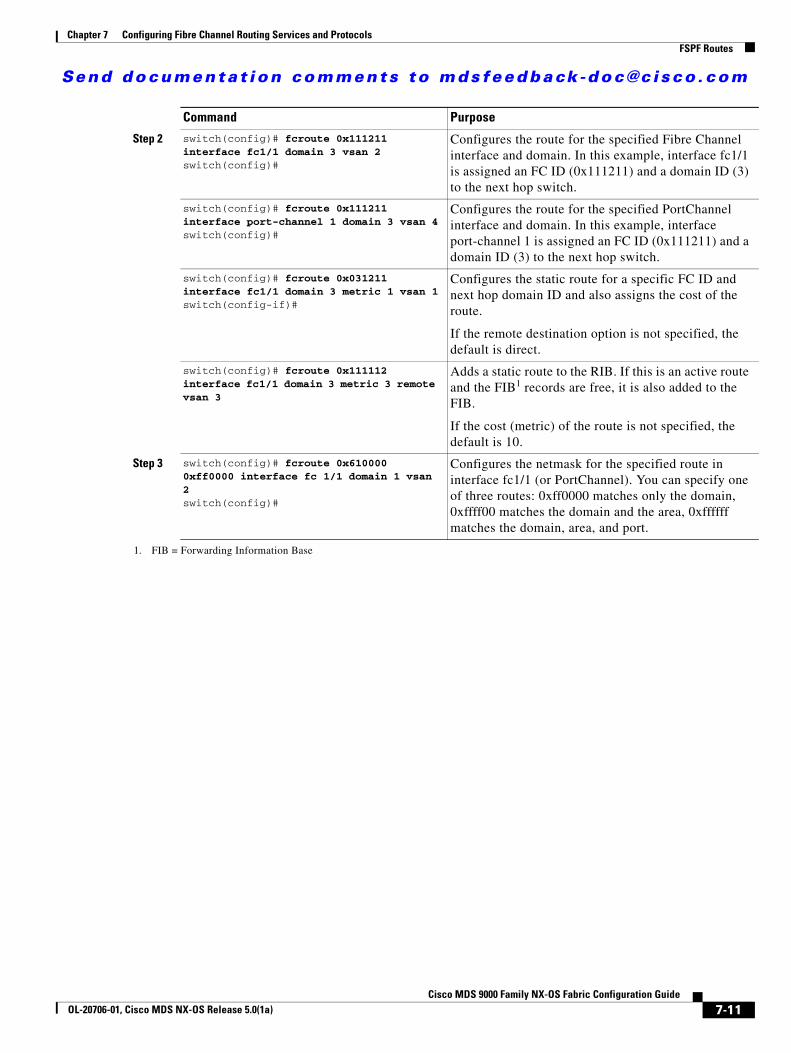
Send documenta t ion comments to mdsfeedback -doc@c i sco .com
Chapter 7 Configuring Fibre Channel Routing Services and ProtocolsFSPF Routes
Step 2 switch(config)# fcroute 0x111211 interface fc1/1 domain 3 vsan 2switch(config)#
Configures the route for the specified Fibre Channel interface and domain. In this example, interface fc1/1 is assigned an FC ID (0x111211) and a domain ID (3) to the next hop switch.
switch(config)# fcroute 0x111211 interface port-channel 1 domain 3 vsan 4switch(config)#
Configures the route for the specified PortChannel interface and domain. In this example, interface port-channel 1 is assigned an FC ID (0x111211) and a domain ID (3) to the next hop switch.
switch(config)# fcroute 0x031211 interface fc1/1 domain 3 metric 1 vsan 1switch(config-if)#
Configures the static route for a specific FC ID and next hop domain ID and also assigns the cost of the route.
If the remote destination option is not specified, the default is direct.
switch(config)# fcroute 0x111112 interface fc1/1 domain 3 metric 3 remote vsan 3
Adds a static route to the RIB. If this is an active route and the FIB1 records are free, it is also added to the FIB.
If the cost (metric) of the route is not specified, the default is 10.
Step 3 switch(config)# fcroute 0x610000 0xff0000 interface fc 1/1 domain 1 vsan 2switch(config)#
Configures the netmask for the specified route in interface fc1/1 (or PortChannel). You can specify one of three routes: 0xff0000 matches only the domain, 0xffff00 matches the domain and the area, 0xffffff matches the domain, area, and port.
1. FIB = Forwarding Information Base
Command Purpose
7-11Cisco MDS 9000 Family NX-OS Fabric Configuration Guide
OL-20706-01, Cisco MDS NX-OS Release 5.0(1a)

Send documenta t ion comments to mdsfeedback -doc@c i sco .com
Chapter 7 Configuring Fibre Channel Routing Services and ProtocolsFSPF Routes
About Broadcast and Multicast RoutingBroadcast and multicast in a Fibre Channel fabric uses the concept of a distribution tree to reach all switches in the fabric.
FSPF provides the topology information to compute the distribution tree. Fibre Channel defines 256 multicast groups and one broadcast address for each VSAN. Switches in the Cisco MDS 9000 Family only use broadcast routing. By default, they use the principal switch as the root node to derive a loop-free distribution tree for multicast and broadcast routing in a VSAN.
Caution All switches in the fabric should run the same multicast and broadcast distribution tree algorithm to ensure the same distribution tree.
To interoperate with other vendor switches (following FC-SW3 guidelines), the SAN-OS and NX-OS 4.1(1b) and later software uses the lowest domain switch as the root to compute the multicast tree in interop mode.
About Multicast Root SwitchBy default, the native (non-interop) mode uses the principal switch as the root. If you change the default, be sure to configure the same mode in all switches in the fabric. Otherwise, multicast traffic could encounter potential loop and frame-drop problems.
Note The operational mode can be different from the configured interop mode. The interop mode always uses the lowest domain switch as the root.
Use the mcast root lowest vsan command to change the multicast root from the principal switch to lowest domain switch.
Setting the Multicast Root SwitchTo use the lowest domain switch for the multicast tree computation, follow these steps:
To display the configured and operational multicast mode and the selected root domain, use the show mcast command.
switch# show mcast vsan 1Multicast root for VSAN 1 Configured root mode : Principal switch Operational root mode : Principal switch Root Domain ID : 0xef(239)
Command Purpose
Step 1 switch# config tswitch(config)#
Enters configuration mode.
Step 2 switch(config)# mcast root lowest vsan 1 Uses the lowest domain switch to compute the multicast tree.
switch(config)# mcast root principal vsan 1 Defaults to using the principal switch to compute the multicast tree.
7-12Cisco MDS 9000 Family NX-OS Fabric Configuration Guide
OL-20706-01, Cisco MDS NX-OS Release 5.0(1a)

Send documenta t ion comments to mdsfeedback -doc@c i sco .com
Chapter 7 Configuring Fibre Channel Routing Services and ProtocolsIn-Order Delivery
In-Order DeliveryIn-Order Delivery (IOD) of data frames guarantees frame delivery to a destination in the same order that they were sent by the originator.
Some Fibre Channel protocols or applications cannot handle out-of-order frame delivery. In these cases, switches in the Cisco MDS 9000 Family preserve frame ordering in the frame flow. The source ID (SID), destination ID (DID), and optionally the originator exchange ID (OX ID) identify the flow of the frame.
On any given switch with IOD enabled, all frames received by a specific ingress port and destined to a certain egress port are always delivered in the same order in which they were received.
Use IOD only if your environment cannot support out-of-order frame delivery.
Tip If you enable the in-order delivery feature, the graceful shutdown feature is not implemented.
This section includes the following topics:
• About Reordering Network Frames, page 7-13
• About Reordering PortChannel Frames, page 7-14
• About Enabling In-Order Delivery, page 7-14
• Enabling In-Order Delivery Globally, page 7-15
• Enabling In-Order Delivery for a VSAN, page 7-15
• Displaying the In-Order Delivery Status, page 7-15
• Configuring the Drop Latency Time, page 7-16
• Displaying Latency Information, page 7-17
About Reordering Network FramesWhen you experience a route change in the network, the new selected path may be faster or less congested than the old route.
Figure 7-5 Route Change Delivery
Switch 1 Switch 2 Switch 3
Switch 4
Frame 2 Frame 1
Frame 4 Frame 3
Old path
New path
8547
4
7-13Cisco MDS 9000 Family NX-OS Fabric Configuration Guide
OL-20706-01, Cisco MDS NX-OS Release 5.0(1a)
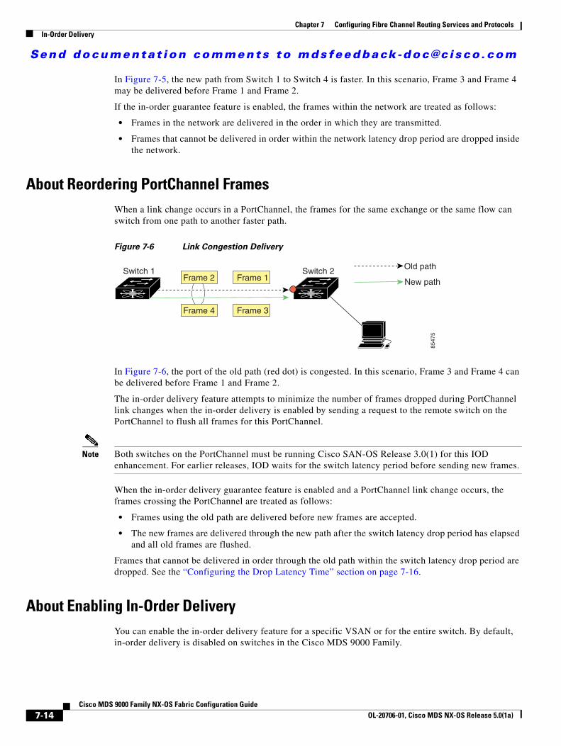
Send documenta t ion comments to mdsfeedback -doc@c i sco .com
Chapter 7 Configuring Fibre Channel Routing Services and ProtocolsIn-Order Delivery
In Figure 7-5, the new path from Switch 1 to Switch 4 is faster. In this scenario, Frame 3 and Frame 4 may be delivered before Frame 1 and Frame 2.
If the in-order guarantee feature is enabled, the frames within the network are treated as follows:
• Frames in the network are delivered in the order in which they are transmitted.
• Frames that cannot be delivered in order within the network latency drop period are dropped inside the network.
About Reordering PortChannel FramesWhen a link change occurs in a PortChannel, the frames for the same exchange or the same flow can switch from one path to another faster path.
Figure 7-6 Link Congestion Delivery
In Figure 7-6, the port of the old path (red dot) is congested. In this scenario, Frame 3 and Frame 4 can be delivered before Frame 1 and Frame 2.
The in-order delivery feature attempts to minimize the number of frames dropped during PortChannel link changes when the in-order delivery is enabled by sending a request to the remote switch on the PortChannel to flush all frames for this PortChannel.
Note Both switches on the PortChannel must be running Cisco SAN-OS Release 3.0(1) for this IOD enhancement. For earlier releases, IOD waits for the switch latency period before sending new frames.
When the in-order delivery guarantee feature is enabled and a PortChannel link change occurs, the frames crossing the PortChannel are treated as follows:
• Frames using the old path are delivered before new frames are accepted.
• The new frames are delivered through the new path after the switch latency drop period has elapsed and all old frames are flushed.
Frames that cannot be delivered in order through the old path within the switch latency drop period are dropped. See the “Configuring the Drop Latency Time” section on page 7-16.
About Enabling In-Order DeliveryYou can enable the in-order delivery feature for a specific VSAN or for the entire switch. By default, in-order delivery is disabled on switches in the Cisco MDS 9000 Family.
Switch 1 Switch 2Frame 2 Frame 1
Frame 4 Frame 3
Old path
New path
8547
5
7-14Cisco MDS 9000 Family NX-OS Fabric Configuration Guide
OL-20706-01, Cisco MDS NX-OS Release 5.0(1a)

Send documenta t ion comments to mdsfeedback -doc@c i sco .com
Chapter 7 Configuring Fibre Channel Routing Services and ProtocolsIn-Order Delivery
Tip We recommend that you only enable this feature when devices that cannot handle any out-of-order frames are present in the switch. Load-balancing algorithms within the Cisco MDS 9000 Family ensure that frames are delivered in order during normal fabric operation. The load-balancing algorithms based on source FC ID, destination FC ID, and exchange ID are enforced in hardware without any performance degradation. However, if the fabric encounters a failure and this feature is enabled, the recovery will be delayed because of an intentional pausing of fabric forwarding to purge the fabric of resident frames that could potentially be forwarded out-of-order.
Enabling In-Order Delivery GloballyTo ensure that the in-order delivery parameters are uniform across all VSANs on an MDS switch, enable in-order delivery globally.
Only enable in-order delivery globally if this is a requirement across your entire fabric. Otherwise, enable IOD only for the VSANs that require this feature.
Note Enable in-order delivery on the entire switch before performing a downgrade to Cisco MDS SAN-OS Release 1.3(3) or earlier.
To enable in-order delivery for the switch, follow these steps:
Enabling In-Order Delivery for a VSANWhen you create a VSAN, that VSAN automatically inherits the global in-order-guarantee value. You can override this global value by enabling or disabling in-order-guarantee for the new VSAN.
To use the lowest domain switch for the multicast tree computation, follow these steps:
Displaying the In-Order Delivery StatusUse the show in-order-guarantee command to display the present configuration status:
Command Purpose
Step 1 switch# config tswitch(config)#
Enters configuration mode.
Step 2 switch(config)# in-order-guarantee Enables in-order delivery in the switch.
switch(config)# no in-order-guarantee Reverts the switch to the factory defaults and disables the in-order delivery feature.
Command Purpose
Step 1 switch# config tswitch(config)#
Enters configuration mode.
Step 2 switch(config)# in-order-guarantee vsan 3452 Enables in-order delivery in VSAN 3452.
switch(config)# no in-order-guarantee vsan 101 Reverts the switch to the factory defaults and disables the in-order delivery feature in VSAN 101.
7-15Cisco MDS 9000 Family NX-OS Fabric Configuration Guide
OL-20706-01, Cisco MDS NX-OS Release 5.0(1a)

Send documenta t ion comments to mdsfeedback -doc@c i sco .com
Chapter 7 Configuring Fibre Channel Routing Services and ProtocolsIn-Order Delivery
switch# show in-order-guaranteeglobal inorder delivery configuration:guaranteed
VSAN specific settingsvsan 1 inorder delivery:guaranteedvsan 101 inorder delivery:not guaranteedvsan 1000 inorder delivery:guaranteedvsan 1001 inorder delivery:guaranteedvsan 1682 inorder delivery:guaranteedvsan 2001 inorder delivery:guaranteedvsan 2009 inorder delivery:guaranteedvsan 2456 inorder delivery:guaranteedvsan 3277 inorder delivery:guaranteedvsan 3451 inorder delivery:guaranteedvsan 3452 inorder delivery:guaranteed
Configuring the Drop Latency TimeYou can change the default latency time for a network, a specified VSAN in a network, or for the entire switch.
To configure the network and the switch drop latency time, follow these steps:
Command Purpose
Step 1 switch# config tswitch(config)#
Enters configuration mode.
Step 2 switch(config)# fcdroplatency network 5000 Configures network drop latency time to be 5000 msec for the network. The valid range is 0 to 60000 msec. The default is 2000 msec.
Note The network drop latency must be computed as the sum of all switch latencies of the longest path in the network.
switch(config)# fcdroplatency network 6000 vsan 3
Configures network drop latency time to be 6000 msec for VSAN 3.
switch(config)# no fcdroplatency network 4500
Removes the current fcdroplatecy network configuration (4500) and reverts the switch to the factory defaults.
Step 3 switch(config)# fcdroplatency switch 4000 Configures switch drop latency time to be 4000 msec for the switch. The valid range is 0 to 60000 msec. The default is 500 msec.
Note The switch drop latency parameter should have the same value in all the switches in the network.
switch(config)# no fcdroplatency switch 4500
Removes the current fcdroplatecy switch configuration (4500) and reverts the switch to the factory defaults.
7-16Cisco MDS 9000 Family NX-OS Fabric Configuration Guide
OL-20706-01, Cisco MDS NX-OS Release 5.0(1a)

Send documenta t ion comments to mdsfeedback -doc@c i sco .com
Chapter 7 Configuring Fibre Channel Routing Services and ProtocolsFlow Statistics Configuration
Displaying Latency InformationYou can view the configured latency parameters using the show fcdroplatency command (see Example 7-1).
Example 7-1 Displays Administrative Distance
switch# show fcdroplatency switch latency value:500 millisecondsglobal network latency value:2000 milliseconds
VSAN specific network latency settingsvsan 1 network latency:5000 millisecondsvsan 2 network latency:2000 millisecondsvsan 103 network latency:2000 millisecondsvsan 460 network latency:500 milliseconds
Flow Statistics ConfigurationFlow statistics count the ingress traffic in the aggregated statistics table. You can collect two kinds of statistics:
• Aggregated flow statistics to count the traffic for a VSAN.
• Flow statistics to count the traffic for a source and destination ID pair in a VSAN.
This section includes the following topics:
• About Flow Statistics, page 7-17
• Counting Aggregated Flow Statistics, page 7-18
• Counting Individual Flow Statistics, page 7-18
• Clearing FIB Statistics, page 7-18
• Displaying Flow Statistics, page 7-18
About Flow StatisticsIf you enable flow counters, you can enable a maximum of 1 K entries for aggregate flow and flow statistics for Generation 1 modules, and 2 K entries for Generation 2 modules. Be sure to assign an unused flow index to a module for each new flow. Flow indexes can be repeated across modules. The number space for flow index is shared between the aggregate flow statistics and the flow statistics.
Generation 1 modules allow a maximum of 1024 flow statements per module. Generation 2 modules allow a maximum of 2048-128 flow statements per module.
7-17Cisco MDS 9000 Family NX-OS Fabric Configuration Guide
OL-20706-01, Cisco MDS NX-OS Release 5.0(1a)

Send documenta t ion comments to mdsfeedback -doc@c i sco .com
Chapter 7 Configuring Fibre Channel Routing Services and ProtocolsFlow Statistics Configuration
Counting Aggregated Flow StatisticsTo count the aggregated flow statistics for a VSAN, follow these steps:
Counting Individual Flow StatisticsTo count the flow statistics for a source and destination FC ID in a VSAN, follow these steps:
Clearing FIB StatisticsUse the clear fcflow stats command to clear the aggregated flow counter (see Examples 7-2 and 7-3).
Example 7-2 Clears Aggregated Flow Counters
switch# clear fcflow stats aggregated module 2 index 1
Example 7-3 Clears Flow Counters for Source and Destination FC IDs
switch# clear fcflow stats module 2 index 1
Displaying Flow StatisticsUse the show fcflow stats commands to view flow statistics (see Example 7-4 to 7-6).
Command Purpose
Step 1 switch# config tswitch(config)#
Enters configuration mode.
Step 2 switch(config)# fcflow stats aggregated module 1 index 1005 vsan 1 switch(config)#
Enables the aggregated flow counter.
switch(config)# no fcflow stats aggregated module 1 index 1005 vsan 1 switch(config)#
Disables the aggregated flow counter.
Command Purpose
Step 1 switch# config tswitch(config)#
Enters configuration mode.
Step 2 switch(config)# fcflow stats module 1 index 1 0x145601 0x5601ff 0xffffff vsan 1 switch(config)#
Enables the flow counter.
Note The source ID and the destination ID are specified in FC ID hex format (for example, 0x123aff). The mask can be one of 0xff0000 or 0xffffff.
switch(config)# no fcflow stats aggregated module 2 index 1001 vsan 2switch(config)#
Disables the flow counter.
7-18Cisco MDS 9000 Family NX-OS Fabric Configuration Guide
OL-20706-01, Cisco MDS NX-OS Release 5.0(1a)

Send documenta t ion comments to mdsfeedback -doc@c i sco .com
Chapter 7 Configuring Fibre Channel Routing Services and ProtocolsFlow Statistics Configuration
Example 7-4 Displays Aggregated Flow Details for the Specified Module
switch# show fcflow stats aggregated module 2 Idx VSAN # frames # bytes---- ---- -------- -------0000 4 387,653 674,235,8750001 6 34,402 2,896,628
Example 7-5 Displays Flow Details for the Specified Module
switch# show fcflow stats module 2 Idx VSAN D ID S ID mask # frames # bytes---- ---- ----------- ----------- ----- -------- -------0000 4 032.001.002 007.081.012 ff.ff.ff 387,653 674,235,8750001 6 004.002.001 019.002.004 ff.00.00 34,402 2,896,628
Example 7-6 Displays Flow Index Usage for the Specified Module
switch# show fcflow stats usage module 2 2 flows configuredconfigured flow : 3,7
Displaying Global FSPF InformationExample 7-7 displays global FSPF information for a specific VSAN:
• Domain number of the switch.
• Autonomous region for the switch.
• Min_LS_arrival: minimum time that must elapse before the switch accepts LSR updates.
• Min_LS_interval: minimum time that must elapse before the switch can transmit an LSR.
Tip If the Min_LS_interval is higher than 10 seconds, the graceful shutdown feature is not implemented.
• LS_refresh_time: interval time lapse between refresh LSR transmissions.
• Max_age: maximum time aa LSR can stay before being deleted.
Example 7-7 Displays FSPF Information for a Specified VSAN
switch# show fspf vsan 1FSPF routing for VSAN 1FSPF routing administration status is enabledFSPF routing operational status is UPIt is an intra-domain routerAutonomous region is 0SPF hold time is 0 msecMinLsArrival = 1000 msec , MinLsInterval = 5000 msecLocal Domain is 0x65(101)Number of LSRs = 3, Total Checksum = 0x0001288b
Protocol constants : LS_REFRESH_TIME = 1800 sec
7-19Cisco MDS 9000 Family NX-OS Fabric Configuration Guide
OL-20706-01, Cisco MDS NX-OS Release 5.0(1a)

Send documenta t ion comments to mdsfeedback -doc@c i sco .com
Chapter 7 Configuring Fibre Channel Routing Services and ProtocolsFlow Statistics Configuration
MAX_AGE = 3600 sec
Statistics counters : Number of LSR that reached MaxAge = 0 Number of SPF computations = 7 Number of Checksum Errors = 0 Number of Transmitted packets : LSU 65 LSA 55 Hello 474 Retranmsitted LSU 0 Number of received packets : LSU 55 LSA 60 Hello 464 Error packets 10
Displaying the FSPF Database Example 7-8 displays a summary of the FSPF database for a specified VSAN. If other parameters are not specified, all LSRs in the database are displayed:
• LSR type
• Domain ID of the LSR owner
• Domain ID of the advertising router
• LSR age
• LSR incarnation member
• Number of links
You could narrow the display to obtain specific information by issuing additional parameters for the domain ID of the LSR owner. For each interface, the following information is also available:
• Domain ID of the neighboring switch
• E port index
• Port index of the neighboring switch
• Link type and cost
Example 7-8 Displays FSPF Database Information
switch# show fspf database vsan 1
FSPF Link State Database for VSAN 1 Domain 0x0c(12)LSR Type = 1Advertising domain ID = 0x0c(12)LSR Age = 1686LSR Incarnation number = 0x80000024LSR Checksum = 0x3cafNumber of links = 2 NbrDomainId IfIndex NbrIfIndex Link Type Cost----------------------------------------------------------------------------- 0x65(101) 0x0000100e 0x00001081 1 500 0x65(101) 0x0000100f 0x00001080 1 500
FSPF Link State Database for VSAN 1 Domain 0x65(101)LSR Type = 1Advertising domain ID = 0x65(101)LSR Age = 1685LSR Incarnation number = 0x80000028LSR Checksum = 0x8443Number of links = 6 NbrDomainId IfIndex NbrIfIndex Link Type Cost----------------------------------------------------------------------------- 0xc3(195) 0x00001085 0x00001095 1 500
7-20Cisco MDS 9000 Family NX-OS Fabric Configuration Guide
OL-20706-01, Cisco MDS NX-OS Release 5.0(1a)

Send documenta t ion comments to mdsfeedback -doc@c i sco .com
Chapter 7 Configuring Fibre Channel Routing Services and ProtocolsDefault Settings
0xc3(195) 0x00001086 0x00001096 1 500 0xc3(195) 0x00001087 0x00001097 1 500 0xc3(195) 0x00001084 0x00001094 1 500 0x0c(12) 0x00001081 0x0000100e 1 500 0x0c(12) 0x00001080 0x0000100f 1 500
FSPF Link State Database for VSAN 1 Domain 0xc3(195)LSR Type = 1Advertising domain ID = 0xc3(195)LSR Age = 1686LSR Incarnation number = 0x80000033LSR Checksum = 0x6799Number of links = 4 NbrDomainId IfIndex NbrIfIndex Link Type Cost----------------------------------------------------------------------------- 0x65(101) 0x00001095 0x00001085 1 500 0x65(101) 0x00001096 0x00001086 1 500 0x65(101) 0x00001097 0x00001087 1 500 0x65(101) 0x00001094 0x00001084 1 500
Displaying FSPF Interfaces Example 7-9 displays the following information for each selected interface.
• Link cost
• Timer values
• Neighbor’s domain ID (if known)
• Local interface number
• Remote interface number (if known)
• FSPF state of the interface
• Interface counters
Example 7-9 Displays FSPF Interface Information
switch# show fspf vsan 1 interface fc1/1FSPF interface fc1/1 in VSAN 1FSPF routing administrative state is activeInterface cost is 500Timer intervals configured, Hello 20 s, Dead 80 s, Retransmit 5 sFSPF State is FULLNeighbor Domain Id is 0x0c(12), Neighbor Interface index is 0x0f100000Statistics counters : Number of packets received : LSU 8 LSA 8 Hello 118 Error packets 0 Number of packets transmitted : LSU 8 LSA 8 Hello 119 Retransmitted LSU 0 Number of times inactivity timer expired for the interface = 0
Default SettingsTable 7-4 lists the default settings for FSPF features.
7-21Cisco MDS 9000 Family NX-OS Fabric Configuration Guide
OL-20706-01, Cisco MDS NX-OS Release 5.0(1a)
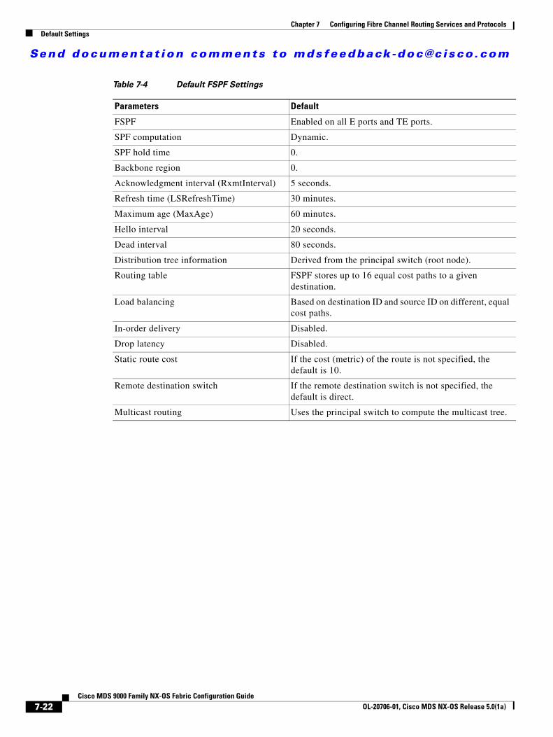
Send documenta t ion comments to mdsfeedback -doc@c i sco .com
Chapter 7 Configuring Fibre Channel Routing Services and ProtocolsDefault Settings
Table 7-4 Default FSPF Settings
Parameters Default
FSPF Enabled on all E ports and TE ports.
SPF computation Dynamic.
SPF hold time 0.
Backbone region 0.
Acknowledgment interval (RxmtInterval) 5 seconds.
Refresh time (LSRefreshTime) 30 minutes.
Maximum age (MaxAge) 60 minutes.
Hello interval 20 seconds.
Dead interval 80 seconds.
Distribution tree information Derived from the principal switch (root node).
Routing table FSPF stores up to 16 equal cost paths to a given destination.
Load balancing Based on destination ID and source ID on different, equal cost paths.
In-order delivery Disabled.
Drop latency Disabled.
Static route cost If the cost (metric) of the route is not specified, the default is 10.
Remote destination switch If the remote destination switch is not specified, the default is direct.
Multicast routing Uses the principal switch to compute the multicast tree.
7-22Cisco MDS 9000 Family NX-OS Fabric Configuration Guide
OL-20706-01, Cisco MDS NX-OS Release 5.0(1a)

Send documenta t ion comments to mdsfeedback -doc@c i sco .com
Cisco MOL-20706-01, Cisco MDS NX-OS Release 5.0(1a)
C H A P T E R 8
Configuring Dense Wavelength Division MultiplexingThis chapter includes the following topics:
• About DWDM, page 8-1
• Configuring X2 DWDM Transceiver Frequency, page 8-1
About DWDMDense Wavelength-Division Multiplexing (DWDM) multiplexes multiple optical carrier signals on a single optical fiber. DWDM uses different wavelengths to carry various signals.
To establish a DWDM link, both ends of an Inter Switch Link (ISL) need to be connected with DWDM SFPs (small form-factor pluggable) at each end of the link. To identify a DWDM link, Fabric Manager discovers the connector type on the Fiber Channel (FC) ports. If the ISL link is associated with the FC ports at each end, then the FC port uses DWDM SFP to connect the links.
Fabric Manager Server discovers FC ports with DWDM SFPs and the ISLs associated with the FC ports. The Fabric Manager Client displays ISL with DWDM attribute on the topology map.
Note The Fabric Shortest Path First (FSPF) database only displays an ISL link, which is connected with DWDM SFPs at both ends.
Configuring X2 DWDM Transceiver FrequencyTo configure X2 DWDM transceiver frequency for a module, follow these steps:
Command Purpose
Step 1 switch# config t Enters configuration mode.
8-1DS 9000 Family NX-OS Fabric Configuration Guide

Send documenta t ion comments to mdsfeedback -doc@c i sco .com
Chapter 8 Configuring Dense Wavelength Division MultiplexingConfiguring X2 DWDM Transceiver Frequency
Note This feature is not supported in other than MDS 9134 modules. In MDS 9134 modules, the 10-Gigabit Ethernet ports must be in down state when you configure the X2 transceiver frequency.
Step 2 switch(config)# module 1 transceiver-frequency x2-eth
Configures the link to fuction as X2 Ethernet.
switch(config)# module 1 transceiver-frequency x2-fc
Configures (default) the link to function as X2 FC.
Command Purpose
8-2Cisco MDS 9000 Family NX-OS Fabric Configuration Guide
OL-20706-01, Cisco MDS NX-OS Release 5.0(1a)

Send documenta t ion comments to mdsfeedback -doc@c i sco .com
Cisco MOL-20706-01, Cisco MDS NX-OS Release 5.0(1a)
C H A P T E R 9
Managing FLOGI, Name Server, FDMI, and RSCN DatabasesThis chapter describes the fabric login (FLOGI) database, the name server features, the Fabric-Device Management Interface, and Registered State Change Notification (RSCN) information provided in the Cisco MDS 9000 Family. It includes the following sections:
• About FLOGI, page 9-1
• Displaying FLOGI Details, page 9-1
• Name Server Proxy, page 9-3
• FDMI, page 9-6
• Displaying FDMI, page 9-6
• RSCN, page 9-8
• Default Settings, page 9-15
About FLOGIIn a Fibre Channel fabric, each host or disk requires an FC ID. Use the show flogi command to verify if a storage device is displayed in the FLOGI table as in the next section. If the required device is displayed in the FLOGI table, the fabric login is successful. Examine the FLOGI database on a switch that is directly connected to the host HBA and connected ports.
Displaying FLOGI DetailsTo view the FLOGI database details, use the show flogi database command. See Examples 9-1 to 9-4.
Example 9-1 Displays Details on the FLOGI Database
switch# show flogi database---------------------------------------------------------------------------INTERFACE VSAN FCID PORT NAME NODE NAME---------------------------------------------------------------------------sup-fc0 2 0xb30100 10:00:00:05:30:00:49:63 20:00:00:05:30:00:49:5efc9/13 1 0xb200e2 21:00:00:04:cf:27:25:2c 20:00:00:04:cf:27:25:2cfc9/13 1 0xb200e1 21:00:00:04:cf:4c:18:61 20:00:00:04:cf:4c:18:61fc9/13 1 0xb200d1 21:00:00:04:cf:4c:18:64 20:00:00:04:cf:4c:18:64fc9/13 1 0xb200ce 21:00:00:04:cf:4c:16:fb 20:00:00:04:cf:4c:16:fb
9-1DS 9000 Family NX-OS Fabric Configuration Guide

Send documenta t ion comments to mdsfeedback -doc@c i sco .com
Chapter 9 Managing FLOGI, Name Server, FDMI, and RSCN DatabasesAbout FLOGI
fc9/13 1 0xb200cd 21:00:00:04:cf:4c:18:f7 20:00:00:04:cf:4c:18:f7
Total number of flogi = 6.
Example 9-2 Displays the FLOGI Database by Interface
switch# show flogi database interface fc1/11INTERFACE VSAN FCID PORT NAME NODE NAME---------- ------ --------- ----------------------- ---------------------fc1/11 1 0xa002ef 21:00:00:20:37:18:17:d2 20:00:00:20:37:18:17:d2fc1/11 1 0xa002e8 21:00:00:20:37:38:a7:c1 20:00:00:20:37:38:a7:c1fc1/11 1 0xa002e4 21:00:00:20:37:6b:d7:18 20:00:00:20:37:6b:d7:18fc1/11 1 0xa002e2 21:00:00:20:37:18:d2:45 20:00:00:20:37:18:d2:45fc1/11 1 0xa002e1 21:00:00:20:37:39:90:6a 20:00:00:20:37:39:90:6afc1/11 1 0xa002e0 21:00:00:20:37:36:0b:4d 20:00:00:20:37:36:0b:4dfc1/11 1 0xa002dc 21:00:00:20:37:5a:5b:27 20:00:00:20:37:5a:5b:27fc1/11 1 0xa002da 21:00:00:20:37:18:6f:90 20:00:00:20:37:18:6f:90fc1/11 1 0xa002d9 21:00:00:20:37:5b:cf:b9 20:00:00:20:37:5b:cf:b9fc1/11 1 0xa002d6 21:00:00:20:37:46:78:97 0:00:00:20:37:46:78:97
Total number of flogi = 10.
Example 9-3 Displays the FLOGI Database by VSAN
switch# show flogi database vsan 1---------------------------------------------------------------------------INTERFACE VSAN FCID PORT NAME NODE NAME ---------------------------------------------------------------------------fc1/3 1 0xef02ef 22:00:00:20:37:18:17:d2 20:00:00:20:37:18:17:d2fc1/3 1 0xef02e8 22:00:00:20:37:38:a7:c1 20:00:00:20:37:38:a7:c1fc1/3 1 0xef02e4 22:00:00:20:37:6b:d7:18 20:00:00:20:37:6b:d7:18fc1/3 1 0xef02e2 22:00:00:20:37:18:d2:45 20:00:00:20:37:18:d2:45fc1/3 1 0xef02e1 22:00:00:20:37:39:90:6a 20:00:00:20:37:39:90:6afc1/3 1 0xef02e0 22:00:00:20:37:36:0b:4d 20:00:00:20:37:36:0b:4dfc1/3 1 0xef02dc 22:00:00:20:37:5a:5b:27 20:00:00:20:37:5a:5b:27fc1/3 1 0xef02da 22:00:00:20:37:18:6f:90 20:00:00:20:37:18:6f:90fc1/3 1 0xef02d9 22:00:00:20:37:5b:cf:b9 20:00:00:20:37:5b:cf:b9fc1/3 1 0xef02d6 22:00:00:20:37:46:78:97 20:00:00:20:37:46:78:97
Total number of flogi = 10.
Example 9-4 Displays the FLOGI Database by FC ID
switch# show flogi database fcid 0xef02e2---------------------------------------------------------------------------INTERFACE VSAN FCID PORT NAME NODE NAME ---------------------------------------------------------------------------fc1/3 1 0xef02e2 22:00:00:20:37:18:d2:45 20:00:00:20:37:18:d2:45
Total number of flogi = 1.
For more information, see the “Default Company ID List” section on page 12-11 and refer to the “Loop Monitoring” section in the Cisco MDS 9000 Family Troubleshooting Guide.
9-2Cisco MDS 9000 Family NX-OS Fabric Configuration Guide
OL-20706-01, Cisco MDS NX-OS Release 5.0(1a)
Send documenta t ion comments to mdsfeedback -doc@c i sco .com
Chapter 9 Managing FLOGI, Name Server, FDMI, and RSCN DatabasesName Server Proxy
Name Server ProxyThe name server functionality maintains a database containing the attributes for all hosts and storage devices in each VSAN. Name servers allow a database entry to be modified by a device that originally registered the information.
The proxy feature is useful when you want to modify (update or delete) the contents of a database entry that was previously registered by a different device.
This section includes the following topics:
• About Registering Name Server Proxies, page 9-3
• Registering Name Server Proxies, page 9-3
• About Rejecting Duplicate pWWN, page 9-3
• Rejecting Duplicate pWWNs, page 9-4
• About Name Server Database Entries, page 9-4
• Displaying Name Server Database Entries, page 9-4
About Registering Name Server ProxiesAll name server registration requests come from the same port whose parameter is registered or changed. If it does not, then the request is rejected.
This authorization enables WWNs to register specific parameters for another node.
Registering Name Server ProxiesTo register the name server proxy, follow these steps:
About Rejecting Duplicate pWWNYou can prevent a malicious or accidental login when using another device’s pWWN by enabling the reject-duplicate-pwwn option. If you disable this option, these pWWNs are allowed to log in to the fabric and replace the first device in the name server database.
Command Purpose
Step 1 switch# config tswitch(config)#
Enters configuration mode.
Step 2 switch(config)# fcns proxy-port 21:00:00:e0:8b:00:26:d0 vsan 2
Configures a proxy port for the specified VSAN.
9-3Cisco MDS 9000 Family NX-OS Fabric Configuration Guide
OL-20706-01, Cisco MDS NX-OS Release 5.0(1a)

Send documenta t ion comments to mdsfeedback -doc@c i sco .com
Chapter 9 Managing FLOGI, Name Server, FDMI, and RSCN DatabasesName Server Proxy
Rejecting Duplicate pWWNsTo reject duplicate pWWNs, follow these steps:
To reject duplicate pWWNs, refer to the Cisco MDS 9000 NX-OS Fabric Configuration Guide.
About Name Server Database EntriesThe name server stores name entries for all hosts in the FCNS database. The name server permits an Nx port to register attributes during a PLOGI (to the name server) to obtain attributes of other hosts. These attributes are deregistered when the Nx port logs out either explicitly or implicitly.
In a multiswitch fabric configuration, the name server instances running on each switch shares information in a distributed database. One instance of the name server process runs on each switch.
Displaying Name Server Database EntriesUse the show fcns command to display the name server database and statistical information for a specified VSAN or for all VSANs (see Examples 9-5 to 9-8).
Example 9-5 Displays the Name Server Database
switch# show fcns database--------------------------------------------------------------------------FCID TYPE PWWN (VENDOR) FC4-TYPE:FEATURE--------------------------------------------------------------------------0x010000 N 50:06:0b:00:00:10:a7:80 scsi-fcp fc-gs 0x010001 N 10:00:00:05:30:00:24:63 (Cisco) ipfc 0x010002 N 50:06:04:82:c3:a0:98:52 (Company 1) scsi-fcp 250 0x010100 N 21:00:00:e0:8b:02:99:36 (Company A) scsi-fcp 0x020000 N 21:00:00:e0:8b:08:4b:20 (Company A) 0x020100 N 10:00:00:05:30:00:24:23 (Cisco) ipfc 0x020200 N 21:01:00:e0:8b:22:99:36 (Company A) scsi-fcp
Example 9-6 Displays the Name Server Database for the Specified VSAN
switch# show fcns database vsan 1VSAN 1:--------------------------------------------------------------------------FCID TYPE PWWN (VENDOR) FC4-TYPE:FEATURE--------------------------------------------------------------------------0x030001 N 10:00:00:05:30:00:25:a3 (Cisco) ipfc0x030101 NL 10:00:00:00:77:99:60:2c (Interphase)
Command Purpose
Step 1 switch# config tswitch(config)#
Enters configuration mode.
Step 2 switch(config)# fcns reject-duplicate-pwwn vsan 1 Logs out devices when they log into the fabric if the pWWNs already exist.
switch(config)# no fcns reject-duplicate-pwwn vsan 1
Overwrites the first device entry in the name server database with the new device having the same pWWN (default).
9-4Cisco MDS 9000 Family NX-OS Fabric Configuration Guide
OL-20706-01, Cisco MDS NX-OS Release 5.0(1a)

Send documenta t ion comments to mdsfeedback -doc@c i sco .com
Chapter 9 Managing FLOGI, Name Server, FDMI, and RSCN DatabasesName Server Proxy
0x030200 N 10:00:00:49:c9:28:c7:010xec0001 NL 21:00:00:20:37:a6:be:14 (Seagate) scsi-fcp
Total number of entries = 4
Example 9-7 Displays the Name Server Database Details
switch# show fcns database detail------------------------VSAN:1 FCID:0x030001------------------------port-wwn (vendor) :10:00:00:05:30:00:25:a3 (Cisco)node-wwn :20:00:00:05:30:00:25:9eclass :2,3node-ip-addr :0.0.0.0ipa :ff ff ff ff ff ff ff fffc4-types:fc4_features:ipfcsymbolic-port-name :symbolic-node-name :port-type :Nport-ip-addr :0.0.0.0fabric-port-wwn :00:00:00:00:00:00:00:00hard-addr :0x000000------------------------VSAN:1 FCID:0xec0200------------------------port-wwn (vendor) :10:00:00:5a:c9:28:c7:01node-wwn :10:00:00:5a:c9:28:c7:01class :3node-ip-addr :0.0.0.0ipa :ff ff ff ff ff ff ff fffc4-types:fc4_features:symbolic-port-name :symbolic-node-name :port-type :Nport-ip-addr :0.0.0.0fabric-port-wwn :22:0a:00:05:30:00:26:1ehard-addr :0x000000Total number of entries = 2
Example 9-8 Displays the Name Server Statistics
switch# show fcns statistics registration requests received = 27deregistration requests received = 0queries received = 57queries sent = 10reject responses sent = 14RSCNs received = 0RSCNs sent = 0
9-5Cisco MDS 9000 Family NX-OS Fabric Configuration Guide
OL-20706-01, Cisco MDS NX-OS Release 5.0(1a)

Send documenta t ion comments to mdsfeedback -doc@c i sco .com
Chapter 9 Managing FLOGI, Name Server, FDMI, and RSCN DatabasesFDMI
FDMICisco MDS 9000 Family switches provide support for the Fabric-Device Management Interface (FDMI) functionality, as described in the FC-GS-4 standard. FDMI enables management of devices such as Fibre Channel Host Bus Adapters (HBAs) through in-band communications. This addition complements the existing Fibre Channel name server and management server functions.
Using the FDMI functionality, the NX-OS software can extract the following management information about attached HBAs and host operating systems without installing proprietary host agents:
• Manufacturer, model, and serial number
• Node name and node symbolic name
• Hardware, driver, and firmware versions
• Host operating system (OS) name and version number
All FDMI entries are stored in persistent storage and are retrieved when the FDMI process is started.
Displaying FDMIUse the show fdmi command to display the FDMI database information (see Examples 9-9 to 9-11).
Example 9-9 Displays All HBA Management Servers
switch# show fdmi databaseRegistered HBA List for VSAN 1 10:00:00:00:c9:32:8d:77 21:01:00:e0:8b:2a:f6:54switch# show fdmi database detailRegistered HBA List for VSAN 1-------------------------------HBA-ID: 10:00:00:00:c9:32:8d:77-------------------------------Node Name :20:00:00:00:c9:32:8d:77Manufacturer :Emulex CorporationSerial Num :0000c9328d77Model :LP9002Model Description:Emulex LightPulse LP9002 2 Gigabit PCI Fibre Channel AdapterHardware Ver :2002606DDriver Ver :SLI-2 SW_DATE:Feb 27 2003, v5-2.20a12ROM Ver :3.11A0Firmware Ver :3.90A7OS Name/Ver :Window 2000CT Payload Len :1300000 Port-id: 10:00:00:00:c9:32:8d:77-------------------------------HBA-ID: 21:01:00:e0:8b:2a:f6:54-------------------------------Node Name :20:01:00:e0:8b:2a:f6:54Manufacturer :QLogic CorporationSerial Num :\74262Model :QLA2342Model Description:QLogic QLA2342 PCI Fibre Channel AdapterHardware Ver :FC5010409-10Driver Ver :8.2.3.10 Beta 2 Test 1 DBG (W2K VI)ROM Ver :1.24Firmware Ver :03.02.13.OS Name/Ver :500
9-6Cisco MDS 9000 Family NX-OS Fabric Configuration Guide
OL-20706-01, Cisco MDS NX-OS Release 5.0(1a)

Send documenta t ion comments to mdsfeedback -doc@c i sco .com
Chapter 9 Managing FLOGI, Name Server, FDMI, and RSCN DatabasesDisplaying FDMI
CT Payload Len :2040 Port-id: 21:01:00:e0:8b:2a:f6:54
Example 9-10 Displays HBA Details for a Specified VSAN
switch# show fdmi database detail vsan 1Registered HBA List for VSAN 1-------------------------------HBA-ID: 10:00:00:00:c9:32:8d:77-------------------------------Node Name :20:00:00:00:c9:32:8d:77Manufacturer :Emulex CorporationSerial Num :0000c9328d77Model :LP9002Model Description:Emulex LightPulse LP9002 2 Gigabit PCI Fibre Channel AdapterHardware Ver :2002606DDriver Ver :SLI-2 SW_DATE:Feb 27 2003, v5-2.20a12ROM Ver :3.11A0Firmware Ver :3.90A7OS Name/Ver :Window 2000CT Payload Len :1300000 Port-id: 10:00:00:00:c9:32:8d:77-------------------------------HBA-ID: 21:01:00:e0:8b:2a:f6:54-------------------------------Node Name :20:01:00:e0:8b:2a:f6:54Manufacturer :QLogic CorporationSerial Num :\74262Model :QLA2342Model Description:QLogic QLA2342 PCI Fibre Channel AdapterHardware Ver :FC5010409-10Driver Ver :8.2.3.10 Beta 2 Test 1 DBG (W2K VI)ROM Ver :1.24Firmware Ver :03.02.13.OS Name/Ver :500CT Payload Len :2040 Port-id: 21:01:00:e0:8b:2a:f6:54
Example 9-11 Displays Details for the Specified HBA Entry
switch# show fdmi database detail hba-id 21:01:00:e0:8b:2a:f6:54 vsan 1
Node Name :20:01:00:e0:8b:2a:f6:54Manufacturer :QLogic CorporationSerial Num :\74262Model :QLA2342Model Description:QLogic QLA2342 PCI Fibre Channel AdapterHardware Ver :FC5010409-10Driver Ver :8.2.3.10 Beta 2 Test 1 DBG (W2K VI)ROM Ver :1.24Firmware Ver :03.02.13.OS Name/Ver :500CT Payload Len :2040 Port-id: 21:01:00:e0:8b:2a:f6:54
9-7Cisco MDS 9000 Family NX-OS Fabric Configuration Guide
OL-20706-01, Cisco MDS NX-OS Release 5.0(1a)
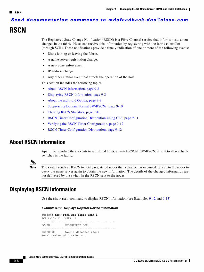
Send documenta t ion comments to mdsfeedback -doc@c i sco .com
Chapter 9 Managing FLOGI, Name Server, FDMI, and RSCN DatabasesRSCN
RSCN The Registered State Change Notification (RSCN) is a Fibre Channel service that informs hosts about changes in the fabric. Hosts can receive this information by registering with the fabric controller (through SCR). These notifications provide a timely indication of one or more of the following events:
• Disks joining or leaving the fabric.
• A name server registration change.
• A new zone enforcement.
• IP address change.
• Any other similar event that affects the operation of the host.
This section includes the following topics:
• About RSCN Information, page 9-8
• Displaying RSCN Information, page 9-8
• About the multi-pid Option, page 9-9
• Suppressing Domain Format SW-RSCNs, page 9-10
• Clearing RSCN Statistics, page 9-10
• RSCN Timer Configuration Distribution Using CFS, page 9-11
• Verifying the RSCN Timer Configuration, page 9-12
• RSCN Timer Configuration Distribution, page 9-12
About RSCN InformationApart from sending these events to registered hosts, a switch RSCN (SW-RSCN) is sent to all reachable switches in the fabric.
Note The switch sends an RSCN to notify registered nodes that a change has occurred. It is up to the nodes to query the name server again to obtain the new information. The details of the changed information are not delivered by the switch in the RSCN sent to the nodes.
Displaying RSCN InformationUse the show rscn command to display RSCN information (see Examples 9-12 and 9-13).
Example 9-12 Displays Register Device Information
switch# show rscn scr-table vsan 1SCR table for VSAN: 1---------------------------------------------FC-ID REGISTERED FOR---------------------------------------------0x1b0300 fabric detected rscnsTotal number of entries = 1
9-8Cisco MDS 9000 Family NX-OS Fabric Configuration Guide
OL-20706-01, Cisco MDS NX-OS Release 5.0(1a)

Send documenta t ion comments to mdsfeedback -doc@c i sco .com
Chapter 9 Managing FLOGI, Name Server, FDMI, and RSCN DatabasesRSCN
Note The SCR table is not configurable. It is populated when hosts send SCR frames with RSCN information. If hosts do not receive RSCN information, then the show rscn scr-table command will not return entries.
Example 9-13 Displays RSCN Counter Information
switch# show rscn statistics vsan 1Statistics for VSAN: 1-------------------------Number of SCR received = 8Number of SCR ACC sent = 8Number of SCR RJT sent = 0Number of RSCN received = 0Number of RSCN sent = 24Number of RSCN ACC received = 24Number of RSCN ACC sent = 0Number of RSCN RJT received = 0Number of RSCN RJT sent = 0Number of SW-RSCN received = 6Number of SW-RSCN sent = 15Number of SW-RSCN ACC received = 15Number of SW-RSCN ACC sent = 6Number of SW-RSCN RJT received = 0Number of SW-RSCN RJT sent = 0
About the multi-pid OptionIf the RSCN multi-pid option is enabled, then RSCNs generated to the registered Nx ports may contain more than one affected port IDs. In this case, zoning rules are applied before putting the multiple affected port IDs together in a single RSCN. By enabling this option, you can reduce the number of RSCNs. For example: Suppose you have two disks (D1, D2) and a host (H) connected to switch 1. Host H is registered to receive RSCNs. D1, D2 and H belong to the same zone. If disks D1 and D2 are online at the same time, then one of the following applies:
• The multi-pid option is disabled on switch 1: two RSCNs are generated to host H—one for the disk D1 and another for disk D2.
• The multi-pid option is enabled on switch 1: a single RSCN is generated to host H, and the RSCN payload lists the affected port IDs (in this case, both D1 and D2).
Note Some Nx ports may not understand multi-pid RSCN payloads. If not, disable the RSCN multi-pid option.
9-9Cisco MDS 9000 Family NX-OS Fabric Configuration Guide
OL-20706-01, Cisco MDS NX-OS Release 5.0(1a)

Send documenta t ion comments to mdsfeedback -doc@c i sco .com
Chapter 9 Managing FLOGI, Name Server, FDMI, and RSCN DatabasesRSCN
Configuring the multi-pid OptionTo configure the multi-pid option, follow these steps:
Suppressing Domain Format SW-RSCNsA domain format SW-RSCN is sent whenever the local switch name or the local switch management IP address changes. This SW-RSCN is sent to all other domains and switches over the ISLs. The remote switches can issue GMAL and GIELN commands to the switch that initiated the domain format SW-RSCN to determine what changed. Domain format SW-RSCNs can cause problems with some non-Cisco MDS switches (refer to the Cisco MDS 9000 Family Switch-to-Switch Interoperability Configuration Guide).
To suppress the transmission of these SW RSCNs over an ISL, follow these steps:
Note You cannot suppress transmission of port address or area address format RSCNs.
Clearing RSCN StatisticsYou can clear the counters and later view the counters for a different set of events. For example, you can keep track of how many RSCNs or SW-RSCNs are generated on a particular event (such as ONLINE or OFFLINE events). You can use these statistics to monitor responses for each event in the VSAN.
Use the clear rscn statistics command to clear the RSCN statistics for the specified VSAN.
switch# clear rscn statistics vsan 1
After clearing the RSCN statistics, you can view the cleared counters by issuing the show rscn command.
switch# show rscn statistics vsan 1Statistics for VSAN: 1-------------------------Number of SCR received = 0Number of SCR ACC sent = 0Number of SCR RJT sent = 0Number of RSCN received = 0Number of RSCN sent = 0Number of RSCN ACC received = 0Number of RSCN ACC sent = 0Number of RSCN RJT received = 0
Command Purpose
Step 1 switch# config tswitch(config)#
Enters configuration mode.
Step 2 switch(config)# rscn multi-pid vsan 105 Sends RSCNs in a multi-pid format for VSAN 105.
Command Purpose
Step 1 switch# config tswitch(config)#
Enters configuration mode.
Step 2 switch(config)# rscn suppress domain-swrscn vsan 105
Suppresses transmission of domain format SW-RSCNs for VSAN 105.
9-10Cisco MDS 9000 Family NX-OS Fabric Configuration Guide
OL-20706-01, Cisco MDS NX-OS Release 5.0(1a)

Send documenta t ion comments to mdsfeedback -doc@c i sco .com
Chapter 9 Managing FLOGI, Name Server, FDMI, and RSCN DatabasesRSCN
Number of RSCN RJT sent = 0Number of SW-RSCN received = 0Number of SW-RSCN sent = 0Number of SW-RSCN ACC received = 0Number of SW-RSCN ACC sent = 0Number of SW-RSCN RJT received = 0Number of SW-RSCN RJT sent = 0
RSCN Timer Configuration Distribution Using CFSBecause the timeout value for each switch is configured manually, a misconfiguration occurs when different switches time out at different times. This means different N ports in a network can receive RSCNs at different times. Cisco Fabric Services (CFS) alleviates this situation by automatically distributing configuration information to all switches in a fabric. This also reduces the number of SW-RSCNs.
RSCN supports two modes, distributed and nondistributed. In distributed mode, RSCN uses CFS to distribute configuration to all switches in the fabric. In nondistributed mode, only the configuration commands on the local switch are affected.
Note All configuration commands are not distributed. Only the rscn event-tov tov vsan vsan command is distributed.
The RSCN timer is registered with CFS during initialization and switchover. For high availability, if the RSCN timer distribution crashes and restarts or a switchover occurs, it resumes normal functionality from the state prior to the crash or switchover.
Note Before performing a downgrade, make sure that you revert the RCSN timer value in your network to the default value. Failure to do so will disable the links across your VSANs and other devices.
Compatibility across various Cisco MDS NX-OS releases during an upgrade or downgrade is supported by conf-check provided by CFS. If you attempt to downgrade from Cisco MDS SAN-OS Release 3.0, you are prompted with a conf-check warning. You are required to disable RSCN timer distribution support before you downgrade.
By default, the RSCN timer distribution capability is disabled and is therefore compatible when upgrading from any Cisco MDS SAN-OS release earlier than Release 3.0.
Configuring the RSCN Timer RSCN maintains a per-VSAN event list queue, where the RSCN events are queued as they are generated. When the first RSCN event is queued, a per VSAN timer starts. Upon time-out, all the events are dequeued and coalesced RSCNs are sent to registered users. The default timer values minimize the number of coalesced RSCNs sent to registered users. Some deployments require smaller event timer values to track changes in the fabric.
Note The RSCN timer value must be the same on all switches in the VSAN. See the “RSCN Timer Configuration Distribution” section on page 9-12.
9-11Cisco MDS 9000 Family NX-OS Fabric Configuration Guide
OL-20706-01, Cisco MDS NX-OS Release 5.0(1a)

Send documenta t ion comments to mdsfeedback -doc@c i sco .com
Chapter 9 Managing FLOGI, Name Server, FDMI, and RSCN DatabasesRSCN
Note Before performing a downgrade, make sure that you revert the RCSN timer value in your network to the default value. Failure to do so will disable the links across your VSANs and other devices.
To configure the RSCN timer, follow these steps:
Verifying the RSCN Timer ConfigurationYou verify the RSCN timer configuration using the show rscn event-tov vsan command.
switch# show rscn event-tov vsan 10Event TOV : 1000 ms
RSCN Timer Configuration DistributionBecause the timeout value for each switch is configured manually, a misconfiguration occurs when different switches time out at different times. This means different N-ports in a network can receive RSCNs at different times. Cisco Fabric Services (CFS) infrastructure alleviates this situation by automatically distributing the RSCN timer configuration information to all switches in a fabric. This also reduces the number of SW-RSCNs. Refer to the Cisco MDS 9000 Family NX-OS System Management Configuration Guide.
RSCN supports two modes, distributed and nondistributed. In distributed mode, RSCN uses CFS to distribute configuration to all switches in the fabric. In nondistributed mode, only the configuration commands on the local switch are affected.
Note All configuration commands are not distributed. Only the rscn event-tov tov vsan vsan command is distributed.
Note Only the RSCN timer configuration is distributed.
Command Purpose
Step 1 switch# config tswitch(config)#
Enters configuration mode.
Step 2 switch(config)# rscn distribute Enables RSCN timer configuration distribution.
Step 3 switch(config)# rscn event-tov 300 vsan 10 Sets the event time-out value in milliseconds for the selected VSAN. In this example, the event time-out value is set to 300 milliseconds for VSAN 12. The range is 0 to 2000 milliseconds. Setting a zero (0) value disables the timer.
switch(config)# no rscn event-tov 300 vsan 10 Reverts to the default value (2000 milliseconds for Fibre Channel VSANs or 1000 milliseconds for FICON VSANs).
Step 4 switch(config)# rscn commit vsan 10 Commits the RSCN timer configuration to be distributed to the switches in VSAN 10.
9-12Cisco MDS 9000 Family NX-OS Fabric Configuration Guide
OL-20706-01, Cisco MDS NX-OS Release 5.0(1a)

Send documenta t ion comments to mdsfeedback -doc@c i sco .com
Chapter 9 Managing FLOGI, Name Server, FDMI, and RSCN DatabasesRSCN
The RSCN timer is registered with CFS during initialization and switchover. For high availability, if the RSCN timer distribution crashes and restarts or a switchover occurs, it resumes normal functionality from the state prior to the crash or switchover.
Note You can determine the compatibility when downgrading to an earlier Cisco MDS NX-OS release using show incompatibility system command. You must disable RSCN timer distribution support before downgrading to an earlier release.
Note By default, the RSCN timer distribution capability is disabled and is compatible when upgrading from any Cisco MDS SAN-OS release earlier than 3.0.
Note For CFS distribution to operate correctly for the RSCN timer configuration, all switches in the fabric must be running Cisco SAN-OS Release 3.0(1) or later, or Cisco NX-OS 4.1(1b).
This section includes the following topics:
• Enabling RSCN Timer Configuration Distribution, page 9-13
• Locking the Fabric, page 9-13
• Committing the RSCN Timer Configuration Changes, page 9-14
• Discarding the RSCN Timer Configuration Changes, page 9-14
• Clearing a Locked Session, page 9-14
• Displaying RSCN Configuration Distribution Information, page 9-14
Enabling RSCN Timer Configuration Distribution
To enable RSCN timer configuration distribution, follow these steps:
Locking the Fabric
The first action that modifies the database creates the pending database and locks the feature in the VSAN. Once you lock the fabric, the following situations apply:
• No other user can make any configuration changes to this feature.
• A copy of the configuration database becomes the pending database along with the first active change.
Command Purpose
Step 1 switch# config t switch(config)#
Enters configuration mode.
Step 2 switch(config)# rscn distribute Enables RSCN timer distribution.
switch(config)# no rscn distribute Disables (default) RSCN timer distribution.
9-13Cisco MDS 9000 Family NX-OS Fabric Configuration Guide
OL-20706-01, Cisco MDS NX-OS Release 5.0(1a)

Send documenta t ion comments to mdsfeedback -doc@c i sco .com
Chapter 9 Managing FLOGI, Name Server, FDMI, and RSCN DatabasesRSCN
Committing the RSCN Timer Configuration Changes
If you commit the changes made to the active database, the configuration is committed to all the switches in the fabric. On a successful commit, the configuration change is applied throughout the fabric and the lock is released.
To commit RSCN timer configuration changes, follow these steps:
Discarding the RSCN Timer Configuration Changes
If you discard (abort) the changes made to the pending database, the configuration database remains unaffected and the lock is released.
To discard RSCN timer configuration changes, follow these steps:
Clearing a Locked Session
If you have changed the RSCN timer configuration and have forgotten to release the lock by either committing or discarding the changes, an administrator can release the lock from any switch in the fabric. If the administrator performs this task, your changes to the pending database are discarded and the fabric lock is released.
Tip The pending database is only available in the volatile directory and are subject to being discarded if the switch is restarted.
To use administrative privileges and release a locked DPVM session, use the clear rscn session vsan command in EXEC mode.
switch# clear rscn session vsan 10
Displaying RSCN Configuration Distribution Information
Use the show cfs application name rscn command to display the registration status for RSCN configuration distribution.
switch# show cfs application name rscn
Enabled : Yes Timeout : 5s Merge Capable : Yes Scope : Logical
Command Purpose
Step 1 switch# config t switch(config)#
Enters configuration mode.
Step 2 switch(config)# rscn commit vsan 10 Commits the RSCN timer changes.
Command Purpose
Step 1 switch# config t switch(config)#
Enters configuration mode.
Step 2 switch(config)# rscn abort vsan 10 Discards the RSCN timer changes and clears the pending configuration database.
9-14Cisco MDS 9000 Family NX-OS Fabric Configuration Guide
OL-20706-01, Cisco MDS NX-OS Release 5.0(1a)
Send documenta t ion comments to mdsfeedback -doc@c i sco .com
Chapter 9 Managing FLOGI, Name Server, FDMI, and RSCN DatabasesDefault Settings
Use the show rscn session status vsan command to display session status information for RSCN configuration distribution.
Note A merge failure results when the RSCN timer values are different on the merging fabrics.
switch# show rscn session status vsan 1Session Parameters for VSAN: 1-------------------------------Last Action : CommitLast Action Result : SuccessLast Action Failure Reason : None
Use the show rscn pending command to display the set of configuration commands that would take effect when you commit the configuration.
Note The pending database includes both existing and modified configuration.
switch# show rscn pendingrscn event-tov 2000 ms vsan 1rscn event-tov 2000 ms vsan 2rscn event-tov 300 ms vsan 10
Use the show rscn pending-diff command to display the difference between pending and active configurations. The following example shows the time-out value for VSAN 10 was changed from 2000 milliseconds (default) to 300 milliseconds.switch# show rscn pending-diff- rscn event-tov 2000 ms vsan 10+ rscn event-tov 300 ms vsan 10
Default SettingsTable 9-1 lists the default settings for RSCN.
Table 9-1 Default RSCN Settings
Parameters Default
RSCN timer value 2000 milliseconds for Fibre Channel VSANs 1000 milliseconds for FICON VSANs
RSCN timer configuration distribution Disabled
9-15Cisco MDS 9000 Family NX-OS Fabric Configuration Guide
OL-20706-01, Cisco MDS NX-OS Release 5.0(1a)

Send documenta t ion comments to mdsfeedback -doc@c i sco .com
Chapter 9 Managing FLOGI, Name Server, FDMI, and RSCN DatabasesDefault Settings
9-16Cisco MDS 9000 Family NX-OS Fabric Configuration Guide
OL-20706-01, Cisco MDS NX-OS Release 5.0(1a)
Send documenta t ion comments to mdsfeedback -doc@c i sco .com
Cisco MOL-20706-01, Cisco MDS NX-OS Release 5.0(1a)
C H A P T E R 10
Discovering SCSI TargetsThis chapter describes the SCSI LUN discovery feature provided in switches in the Cisco MDS 9000 Family. It includes the following sections:
• About SCSI LUN Discovery, page 10-1
• Displaying SCSI LUN Information, page 10-2
About SCSI LUN DiscoverySmall Computer System Interface (SCSI) targets include disks, tapes, and other storage devices. These targets do not register logical unit numbers (LUNs) with the name server.
The name server requires LUN information for the following reasons:
• To display LUN storage device information so an NMS can access this information.
• To report device capacity, serial number, and device ID information.
• To register the initiator and target features with the name server.
The SCSI LUN discovery feature uses the local domain controller Fibre Channel address. It uses the local domain controller as the source FC ID, and performs SCSI INQUIRY, REPORT LUNS, and READ CAPACITY commands on SCSI devices.
The SCSI LUN discovery feature is initiated on demand, through CLI or SNMP. This information is also synchronized with neighboring switches, if those switches belong to the Cisco MDS 9000 Family.
This section includes the following topics:
• About Starting SCSI LUN Discovery, page 10-1
• Starting SCSI LUN Discovery, page 10-2
• About Initiating Customized Discovery, page 10-2
• Initiating Customized Discovery, page 10-2
About Starting SCSI LUN DiscoverySCSI LUN discovery is done on demand.
Only Nx ports that are present in the name server database and that are registered as FC4 Type = SCSI_FCP are discovered.
10-1DS 9000 Family NX-OS Fabric Configuration Guide
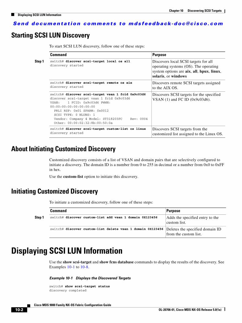
Send documenta t ion comments to mdsfeedback -doc@c i sco .com
Chapter 10 Discovering SCSI TargetsDisplaying SCSI LUN Information
Starting SCSI LUN DiscoveryTo start SCSI LUN discovery, follow one of these steps:
About Initiating Customized Discovery Customized discovery consists of a list of VSAN and domain pairs that are selectively configured to initiate a discovery. The domain ID is a number from 0 to 255 in decimal or a number from 0x0 to 0xFF in hex.
Use the custom-list option to initiate this discovery.
Initiating Customized DiscoveryTo initiate a customized discovery, follow one of these steps:
Displaying SCSI LUN InformationUse the show scsi-target and show fcns database commands to display the results of the discovery. See Examples 10-1 to 10-8.
Example 10-1 Displays the Discovered Targets
switch# show scsi-target status discovery completed
Command Purpose
Step 1 switch# discover scsi-target local os alldiscovery started
Discovers local SCSI targets for all operating systems (OS). The operating system options are aix, all, hpux, linux, solaris, or windows
switch# discover scsi-target remote os aixdiscovery started
Discovers remote SCSI targets assigned to the AIX OS.
switch# discover scsi-target vsan 1 fcid 0x9c03d6 discover scsi-target vsan 1 fcid 0x9c03d6VSAN: 1 FCID: 0x9c03d6 PWWN: 00:00:00:00:00:00:00:00 PRLI RSP: 0x01 SPARM: 0x0012 SCSI TYPE: 0 NLUNS: 1 Vendor: Company 4 Model: ST318203FC Rev: 0004 Other: 00:00:02:32:8b:00:50:0a
Discovers SCSI targets for the specified VSAN (1) and FC ID (0x9c03d6).
switch# discover scsi-target custom-list os linuxdiscovery started
Discovers SCSI targets from the customized list assigned to the Linux OS.
Command Purpose
Step 1 switch# discover custom-list add vsan 1 domain 0X123456 Adds the specified entry to the custom list.
switch# discover custom-list delete vsan 1 domain 0X123456 Deletes the specified domain ID from the custom list.
10-2Cisco MDS 9000 Family NX-OS Fabric Configuration Guide
OL-20706-01, Cisco MDS NX-OS Release 5.0(1a)

Send documenta t ion comments to mdsfeedback -doc@c i sco .com
Chapter 10 Discovering SCSI TargetsDisplaying SCSI LUN Information
Note This command takes several minutes to complete, especially if the fabric is large or if several devices are slow to respond.
Example 10-2 Displays the FCNS Database
switch# show fcns database
VSAN 1:--------------------------------------------------------------------------FCID TYPE PWWN (VENDOR) FC4-TYPE:FEATURE--------------------------------------------------------------------------0xeb0000 N 21:01:00:e0:8b:2a:f6:54 (Qlogic) scsi-fcp:init0xeb0201 NL 10:00:00:00:c9:32:8d:76 (Emulex) scsi-fcp:init
Total number of entries = 2
VSAN 7:--------------------------------------------------------------------------FCID TYPE PWWN (VENDOR) FC4-TYPE:FEATURE--------------------------------------------------------------------------0xed0001 NL 21:00:00:04:cf:fb:42:f8 (Seagate) scsi-fcp:target
Total number of entries = 1
VSAN 2002:--------------------------------------------------------------------------FCID TYPE PWWN (VENDOR) FC4-TYPE:FEATURE--------------------------------------------------------------------------0xcafe00 N 20:03:00:05:30:00:2a:20 (Cisco) FICON:CUP
Total number of entries = 1
Example 10-3 Displays the Discovered Target Disks
switch# show scsi-target disk --------------------------------------------------------------------------------VSAN FCID PWWN VENDOR MODEL REV --------------------------------------------------------------------------------1 0x9c03d6 21:00:00:20:37:46:78:97 Company 4 ST318203FC 00041 0x9c03d9 21:00:00:20:37:5b:cf:b9 Company 4 ST318203FC 00041 0x9c03da 21:00:00:20:37:18:6f:90 Company 4 ST318203FC 00041 0x9c03dc 21:00:00:20:37:5a:5b:27 Company 4 ST318203FC 00041 0x9c03e0 21:00:00:20:37:36:0b:4d Company 4 ST318203FC 00041 0x9c03e1 21:00:00:20:37:39:90:6a Company 4 ST318203 CLAR18 38441 0x9c03e2 21:00:00:20:37:18:d2:45 Company 4 ST318203 CLAR18 38441 0x9c03e4 21:00:00:20:37:6b:d7:18 Company 4 ST318203 CLAR18 38441 0x9c03e8 21:00:00:20:37:38:a7:c1 Company 4 ST318203FC 00041 0x9c03ef 21:00:00:20:37:18:17:d2 Company 4 ST318203FC 0004
Example 10-4 Displays the Discovered LUNs for All Operating Systems
switch# show scsi-target lun os allST336607FC from SEAGATE (Rev 0006)FCID is 0xed0001 in VSAN 7, PWWN is 21:00:00:04:cf:fb:42:f8--------------------------------------------------------------------------------OS LUN Capacity Status Serial Number Device-Id (MB)
10-3Cisco MDS 9000 Family NX-OS Fabric Configuration Guide
OL-20706-01, Cisco MDS NX-OS Release 5.0(1a)

Send documenta t ion comments to mdsfeedback -doc@c i sco .com
Chapter 10 Discovering SCSI TargetsDisplaying SCSI LUN Information
--------------------------------------------------------------------------------WIN 0x0 36704 Online 3JA1B9QA00007338 C:1 A:0 T:3 20:00:00:04:cf:fb:42:f8AIX 0x0 36704 Online 3JA1B9QA00007338 C:1 A:0 T:3 20:00:00:04:cf:fb:42:f8SOL 0x0 36704 Online 3JA1B9QA00007338 C:1 A:0 T:3 20:00:00:04:cf:fb:42:f8LIN 0x0 36704 Online 3JA1B9QA00007338 C:1 A:0 T:3 20:00:00:04:cf:fb:42:f8HP 0x0 36704 Online 3JA1B9QA00007338 C:1 A:0 T:3 20:00:00:04:cf:fb:42:f8
Example 10-5 Displays the Discovered LUNs for the Solaris OS
switch# show scsi-target lun os solarisST336607FC from SEAGATE (Rev 0006)FCID is 0xed0001 in VSAN 7, PWWN is 21:00:00:04:cf:fb:42:f8--------------------------------------------------------------------------------OS LUN Capacity Status Serial Number Device-Id (MB)--------------------------------------------------------------------------------SOL 0x0 36704 Online 3JA1B9QA00007338 C:1 A:0 T:3 20:00:00:04:cf:fb:42:f8
The following command displays the port WWN that is assigned to each OS (Windows, AIX, Solaris, Linux, or HPUX)
Example 10-6 Displays the pWWNs for each OS
switch# show scsi-target pwwn------------------------------OS PWWN------------------------------WIN 24:91:00:05:30:00:2a:1eAIX 24:92:00:05:30:00:2a:1eSOL 24:93:00:05:30:00:2a:1eLIN 24:94:00:05:30:00:2a:1eHP 24:95:00:05:30:00:2a:1e
Example 10-7 Displays Customized Discovered Targets
switch# show scsi-target custom-list --------------- VSAN DOMAIN --------------- 1 56
Use the show scsi-target auto-poll command to verify automatic discovery of SCSI targets that come online. The internal uuid number indicates that a CSM or an IPS module is in the chassis.
Example 10-8 Displays Automatically Discovered Targets
switch# show scsi-target auto-poll auto-polling is enabled, poll_start:0 poll_count:1 poll_type:0 USERS OF AUTO POLLING ---------------------uuid:54
10-4Cisco MDS 9000 Family NX-OS Fabric Configuration Guide
OL-20706-01, Cisco MDS NX-OS Release 5.0(1a)

Send documenta t ion comments to mdsfeedback -doc@c i sco .com
Cisco MOL-20706-01, Cisco MDS NX-OS Release 5.0(1a)
C H A P T E R 11
Configuring FICONFibre Connection (FICON) interface capabilities enhance the Cisco MDS 9000 Family by supporting both open systems and mainframe storage network environments. The control unit port (CUP) also is supportedy which allows in-band management of the switch from FICON processors.
This chapter includes the following sections:
• About FICON, page 11-1
• FICON Port Numbering, page 11-7
• Configuring FICON, page 11-15
• Configuring FICON Ports, page 11-24
• FICON Configuration Files, page 11-32
• Port Swapping, page 11-36
• FICON Tape Acceleration, page 11-38
• Configuring XRC Acceleration, page 11-42
• Moving a FICON VSAN to an Offline State, page 11-42
• CUP In-Band Management, page 11-42
• Displaying FICON Information, page 11-44
• Default Settings, page 11-51
About FICONThe Cisco MDS 9000 Family supports the Fibre Channel Protocol (FCP), FICON, iSCSI, and FCIP capabilities within a single, high-availability platform (see Figure 11-1).
The FICON feature is not supported on:
• Cisco MDS 9120 switches
• Cisco MDS 9124 switches
• Cisco MDS 9140 switches
• The 32-port Fibre Channel switching module
• Cisco Fabric Switch for HP c-Class BladeSystem
• Cisco Fabric Switch for IBM BladeSystem
11-1DS 9000 Family NX-OS Fabric Configuration Guide

Send documenta t ion comments to mdsfeedback -doc@c i sco .com
Chapter 11 Configuring FICONAbout FICON
FCP and FICON are different FC4 protocols and their traffic is independent of each other. Devices using these protocols should be isolated using VSANs.
The fabric binding feature helps prevent unauthorized switches from joining the fabric or disrupting current fabric operations (refer to the Cisco MDS 9000 Family NX-OS Security Configuration Guide). The Registered Link Incident Report (RLIR) application provides a method for a switch port to send an LIR to a registered Nx port.
Figure 11-1 Shared System Storage Network
This section includes the following topics:
• FICON Requirements, page 11-2
• MDS-Specific FICON Advantages, page 11-3
• FICON Cascading, page 11-7
• FICON VSAN Prerequisites, page 11-7
FICON RequirementsThe FICON feature has the following requirements:
• You can implement FICON features in the following switches:
– Any switch in the Cisco MDS 9500 Series
– Any switch in the Cisco MDS 9200 Series (including the Cisco MDS 9222i Multiservice Modular Switch)
– Cisco MDS 9134 Multilayer Fabric Switch
– MDS 9000 Family 18/4-Port Multiservice Module
• You need the MAINFRAME_PKG license to configure FICON parameters.
• To extend your FICON configuration over a WAN link using FCIP, you need the appropriate SAN_EXTN_OVER_IP license for the module you are using. For more information, refer to the Cisco NX-OS Family Licensing Guide.
Openstorage
Opensystems
Controlunit
Mainframesystems
Open systems VSANs
FICON VSAN
1052
11
11-2Cisco MDS 9000 Family NX-OS Fabric Configuration Guide
OL-20706-01, Cisco MDS NX-OS Release 5.0(1a)

Send documenta t ion comments to mdsfeedback -doc@c i sco .com
Chapter 11 Configuring FICONAbout FICON
MDS-Specific FICON AdvantagesThis section explains the additional FICON advantages in Cisco MDS switches and includes the following topics:
• Fabric Optimization with VSANs, page 11-3
• FCIP Support, page 11-4
• PortChannel Support, page 11-4
• VSANs for FICON and FCP Mixing, page 11-5
• Cisco MDS-Supported FICON Features, page 11-5
Fabric Optimization with VSANs
Generally, separate physical fabrics have a high level of switch management and have a higher implementation cost. The ports in each island also may be over-provisioned depending on the fabric configuration.
By using the Cisco MDS-specific VSAN technology, you can have greater efficiency between these physical fabrics by lowering the cost of over-provisioning and reducing the number of switches to be managed. VSANs also help you to move unused ports nondisruptively and provide a common redundant physical infrastructure (see Figure 11-2).
Figure 11-2 VSAN-Specific Fabric Optimization
Separate physical fabrics Collapsed fabric withVSANs
SAN island fordepartment no.1
SAN island fordepartment no. 2
SAN island fordepartment no. 3
Applicationservers
Diskarrays
Department no. 1
Department no. 2VSAN
Department no.3VSAN
Commonstorage poolfound among
VSANs
1052
12
11-3Cisco MDS 9000 Family NX-OS Fabric Configuration Guide
OL-20706-01, Cisco MDS NX-OS Release 5.0(1a)

Send documenta t ion comments to mdsfeedback -doc@c i sco .com
Chapter 11 Configuring FICONAbout FICON
VSANs enable global SAN consolidation by allowing you to convert existing SAN islands into virtual SAN islands on a single physical network. It provides hardware-enforced security and separation between applications or departments to allow coexistence on a single network. It also allows virtual rewiring to consolidate your storage infrastructure. You can move assets between departments or applications without the expense and disruption of physical relocation of equipment.
Note While you can configure VSANs in any Cisco MDS switch, you only can enable FICON inupto eight of these VSANs. The number of VSANs configured depends on the platform.
Mainframe users can think of VSANs as being like FICON LPARs in the MDS SAN fabric. You can partition switch resources into FICON LPARs (VSANs) that are isolated from each other, in much the same way that you can partition resources on a zSeries or DS8000. Each VSAN has its own set of fabric services (such as fabric server and name server), FICON CUP, domain ID, Fabric Shortest Path First (FSPF) routing, operating mode, IP address, and security profile.
FICON LPARs can span line cards and are dynamic in size. For example, one FICON LPAR with 10 ports can span 10 different line cards. FICON LPARs can also include ports on more than one switch in a cascaded configuration. The consistent fairness of the Cisco MDS 9000 switching architecture means that “all ports are created equal,” simplifying provisioning by eliminating the “local switching” issues seen on other vendors’ platforms.
Addition of ports to a FICON LPAR is a nondisruptive process. The maximum number of ports for a FICON LPAR is 255 due to FICON addressing limitations.
FCIP Support
The multilayer architecture of the Cisco MDS 9000 Family enables a consistent feature set over a protocol-agnostic switch fabric. Cisco MDS 9500 Series and 9200 Series switches transparently integrate Fibre Channel, FICON, and Fibre Channel over IP (FCIP) in one system. The FICON over FCIP feature enables cost-effective access to remotely located mainframe resources. With the Cisco MDS 9000 Family platform, storage replication services such as IBM PPRC and XRC can be extended over metro to global distances using ubiquitous IP infrastructure which simplifies business continuance strategies.
Refer to the Cisco MDS 9000 Family NX-OS IP Services Configuration Guide.
PortChannel Support
The Cisco MDS implementation of FICON provides support for efficient utilization and increased availability of Inter-Switch Links (ISLs) necessary to build stable large-scale SAN environments. PortChannels ensure an enhanced ISL availability and performance in Cisco MDS switches.
Refer to the Cisco MDS 9000 Family NX-OS Interfaces Configuration Guide for more information on PortChannels.
11-4Cisco MDS 9000 Family NX-OS Fabric Configuration Guide
OL-20706-01, Cisco MDS NX-OS Release 5.0(1a)

Send documenta t ion comments to mdsfeedback -doc@c i sco .com
Chapter 11 Configuring FICONAbout FICON
VSANs for FICON and FCP Mixing
Cisco MDS 9000 Family FICON-enabled switches simplify deployment of even the most complex mixed environments. Multiple logical FICON, Z-Series Linux/FCP, and Open-Systems Fibre Channel Protocol (FCP) fabrics can be overlaid onto a single physical fabric by simply creating VSANs as required for each service. VSANs provide both hardware isolation and protocol specific fabric services, eliminating the complexity and potential instability of zone-based mixed schemes.
By default, the FICON feature is disabled in all switches in the Cisco MDS 9000 Family. When the FICON feature is disabled, FC IDs can be allocated seamlessly. Mixed environments are addressed by the Cisco NX-OS software. The challenge of mixing FCP and FICON protocols are addressed by Cisco MDS switches when implementing VSANs.
Switches and directors in the Cisco MDS 9000 Family support FCP and FICON protocol mixing at the port level. If these protocols are mixed in the same switch, you can use VSANs to isolate FCP and FICON ports.
Tip When creating a mixed environment, place all FICON devices in one VSAN (other than the default VSAN) and segregate the FCP switch ports in a separate VSAN (other than the default VSAN). This isolation ensures proper communication for all connected devices.
Cisco MDS-Supported FICON Features
The Cisco MDS 9000 Family FICON features include:
• Flexibility and investment protection—The Cisco MDS 9000 Family shares common switching and service modules across the Cisco MDS 9500 Series and the 9200 Series.
Refer to the Cisco MDS 9500 Series Hardware Installation Guide and the Cisco MDS 9200 Series Hardware Installation Guide.
• High-availability FICON-enabled director—The Cisco MDS 9500 Series combines nondisruptive software upgrades, stateful process restart and failover, and full redundancy of all major components for a new standard in director-class availability. It supports up to 528 autosensing, 4/2/1-Gbps, 10-Gbps, FICON or FCP ports in any combination in a single chassis. Refer to the Cisco MDS 9000 Family NX-OS High Availability and Redundancy Configuration Guide.
• Infrastructure protection—Common software releases provide infrastructure protection across all Cisco MDS 9000 platforms. Refer to the Cisco MDS 9000 Family NX-OS Software Upgrade and Downgrade Guide.
• VSAN technology—The Cisco MDS 9000 Family provides VSAN technology for hardware-enforced, isolated environments within a single physical fabric for secure sharing of physical infrastructure and enhanced FICON mixed support. See Chapter 2, “Configuring and Managing VSANs.”
• Port-level configurations—There are BB_credits, beacon mode, and port security for each port. Refer to the Cisco MDS 9000 Family NX-OS Interfaces Configuration Guide for information about buffer-to-buffer credits, beacon LEDs, and trunking.
• Alias name configuration—Provides user-friendly aliases instead of the WWN for switches and attached node devices. See Chapter 5, “Configuring and Managing Zones.”
• Comprehensive security framework—The Cisco MDS 9000 Family supports RADIUS and TACACS+ authentication, Simple Network Management Protocol Version 3 (SNMPv3), role-based access control, Secure Shell Protocol (SSH), Secure File Transfer Protocol (SFTP), VSANs, hardware-enforced zoning, ACLs, fabric binding, Fibre Channel Security Protocol (FC-SP), LUN
11-5Cisco MDS 9000 Family NX-OS Fabric Configuration Guide
OL-20706-01, Cisco MDS NX-OS Release 5.0(1a)

Send documenta t ion comments to mdsfeedback -doc@c i sco .com
Chapter 11 Configuring FICONAbout FICON
zoning, read-only zones, and VSAN-based access control. Refer to the Cisco MDS 9000 Family NX-OS Security Configuration Guide for information about RADIUS, TACACS+, FC-SP, and DHCHAP.
• Traffic encryption—IPSec is supported over FCIP. You can encrypt FICON and Fibre Channel traffic that is carried over FCIP. Refer to the Cisco MDS 9000 Family NX-OS Security Configuration Guide.
• Local accounting log—View the local accounting log to locate FICON events. For more information about MSCHAP authentication, and local AAA services, refer to the Cisco MDS 9000 Family NX-OS Security Configuration Guide.
• Unified storage management—Cisco MDS 9000 FICON-enabled switches are fully IBM CUP standard compliant for in-band management using the IBM S/A OS/390 I/O operations console. See the “CUP In-Band Management” section on page 11-42.
• Port address-based configurations—Configure port name, blocked or unblocked state, and the prohibit connectivity attributes can be configured on the ports. See the “Configuring FICON Ports” section on page 11-24.
• You can display the following information:
– Individual Fibre Channel ports, such as the port name, port number, Fibre Channel address, operational state, type of port, and login data.
– Nodes attached to ports.
– Port performance and statistics.
• Configuration files—Store and apply configuration files. See the “FICON Configuration Files” section on page 11-32.
• FICON and Open Systems Management Server features if installed. —See the “VSANs for FICON and FCP Mixing” section on page 11-5.
• Enhanced cascading support—See the “CUP In-Band Management” section on page 11-42.
• Date and time—Set the date and time on the switch. See the “Allowing the Host to Control the Timestamp” section on page 11-21.
• Configure SNMP trap recipients and community names—See the “Configuring SNMP Control of FICON Parameters” section on page 11-22.
• Call Home configurations—Configure the director name, location, description, and contact person. Refer to the Cisco MDS 9000 Family NX-OS System Management Configuration Guide.
• Configure preferred domain ID, FC ID persistence, and principal switch priority—For information about configuring domain parameters, refer to the Cisco MDS 9000 Family NX-OS System Management Configuration Guide.
• Sophisticated SPAN diagnostics—The Cisco MDS 9000 Family provides industry-first intelligent diagnostics, protocol decoding, and network analysis tools as well as integrated Call Home capability for added reliability, faster problem resolution, and reduced service costs. For information about monitoring network traffic using SPAN, refer to the Cisco MDS 9000 Family NX-OS System Management Configuration Guide.
• Configure R_A_TOV, E_D_TOV—— See the “Fibre Channel Time-Out Values” section on page 12-5.
• Director-level maintenance tasks—Perform maintenance tasks for the director including maintaining firmware levels, accessing the director logs, and collecting data to support failure analysis. For information about monitoring system processes and logs refer to the Cisco MDS 9000 Family NX-OS System Management Configuration Guide.
11-6Cisco MDS 9000 Family NX-OS Fabric Configuration Guide
OL-20706-01, Cisco MDS NX-OS Release 5.0(1a)

Send documenta t ion comments to mdsfeedback -doc@c i sco .com
Chapter 11 Configuring FICONFICON Port Numbering
• Port-level incident alerts—Display and clear port-level incident alerts. See the “Clearing RLIR Information” section on page 11-32.
FICON CascadingThe Cisco MDS NX-OS software allows multiple switches in a FICON network. To configure multiple switches, you must enable and configure fabric binding in that switch and refer to the Cisco MDS 9000 Family NX-OS Security Configuration Guide).
FICON VSAN PrerequisitesTo ensure that a FICON VSAN is operationally up, be sure to verify the following requirements:
• Set the default zone to permit, if you are not using the zoning feature. See the “About the Default Zone” section on page 5-10.
• Enable in-order delivery on the VSAN. See Chapter 7, “Configuring Fibre Channel Routing Services and Protocols.”
• Enable (and if required, configure) fabric binding on the VSAN. For more information about Fabric Binding, refer to the Cisco MDS 9000 Family NX-OS Security Configuration Guide.
• Verify that conflicting persistent FC IDs do not exist in the switch. For information about configuring domain parameters, refer to the Cisco MDS 9000 Family NX-OS System Management Configuration Guide.
• Verify that the configured domain ID and requested domain ID match. For information about configuring domain parameters, refer to the Cisco MDS 9000 Family NX-OS System Management Configuration Guide.
• Add the CUP (area FE) to the zone, if you are using zoning. See the “CUP In-Band Management” section on page 11-42.
If any of these requirements are not met, the FICON feature cannot be enabled.
FICON Port NumberingWith reference to the FICON feature, ports in Cisco MDS switches are identified by a statically defined 8-bit value known as the port number. A maximum of 255 port numbers are available. You can use the following port numbering schemes:
• Default port numbers based on the chassis type
• Reserved port numbers
This section includes the following topics:
• Default FICON Port Numbering Scheme, page 11-8
• Port Addresses, page 11-10
• Implemented and Unimplemented Port Addresses, page 11-11
• About the Reserved FICON Port Numbering Scheme, page 11-11
• Installed and Uninstalled Ports, page 11-11
• FICON Port Numbering Guidelines, page 11-12
11-7Cisco MDS 9000 Family NX-OS Fabric Configuration Guide
OL-20706-01, Cisco MDS NX-OS Release 5.0(1a)

Send documenta t ion comments to mdsfeedback -doc@c i sco .com
Chapter 11 Configuring FICONFICON Port Numbering
• Assigning FICON Port Numbers to Slots, page 11-12
• Displaying the FICON Port Number Assignments, page 11-12
• About Port Numbers for FCIP and PortChannel, page 11-13
• About the Reserved FICON Port Numbering Scheme, page 11-11
• FC ID Allocation, page 11-14
Note You must enable FICON on the switch before reserving FICON port number (see the “About Enabling FICON on a VSAN” section on page 11-15).
Default FICON Port Numbering SchemeDefault FICON port numbers are assigned by the Cisco MDS NX-OS software based on the module and the slot in the chassis. The first port in a switch always starts with a zero (0) (see Figure 11-3).
Figure 11-3 Default FICON Port Number in Numbering on the Cisco MDS 9000 Family Switch
The default FICON port number is assigned based on the front panel location of the port and is specific to the slot in which the module resides. Thirty-two (32) port numbers are assigned to each slot on all Cisco MDS 9000 Family switches except for the Cisco MDS 9513 Director, which has 16 port numbers assigned for each slot. These default numbers are assigned regardless of the module’s physical presence in the chassis, the port status (up or down), or the number of ports on the module (4, 12, 16, 24, or 48). If a module has fewer ports than the number of port numbers assigned to the slot, then the excess port numbers are unused. If a module has more ports than the number of port numbers assigned to the slot, the excess ports cannot be used for FICON traffic unless you manually assign the port numbers.
Note You can use the ficon slot assign port-numbers command to make use of any excess ports by manually assigning more port numbers to the slots. Before doing this, however, we recommend that you review the default port number assignments for Cisco MDS 9000 switches shown in Table 11-3 on page 11-52 Table 11-1, and that you read the following sections to gain a complete understanding of FICON port
0 1 2 3 4 5 6 7 8 9 10 11 11 13 14 15
Module 1 16-Port module
32 33 34 35 36 37 38 39 40 41 42 43 44 45 46 47
Module 2 16-Port module
1052
17
11-8Cisco MDS 9000 Family NX-OS Fabric Configuration Guide
OL-20706-01, Cisco MDS NX-OS Release 5.0(1a)
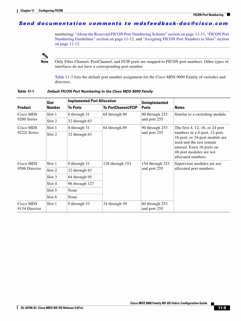
Send documenta t ion comments to mdsfeedback -doc@c i sco .com
Chapter 11 Configuring FICONFICON Port Numbering
numbering: “About the Reserved FICON Port Numbering Scheme” section on page 11-11, “FICON Port Numbering Guidelines” section on page 11-12, and “Assigning FICON Port Numbers to Slots” section on page 11-12.
Note Only Fibre Channel, PortChannel, and FCIP ports are mapped to FICON port numbers. Other types of interfaces do not have a corresponding port number.
Table 11-3 lists the default port number assignment for the Cisco MDS 9000 Family of switches and directors.
Table 11-1 Default FICON Port Numbering in the Cisco MDS 9000 Family
ProductSlot Number
Implemented Port Allocation Unimplemented Ports NotesTo Ports To PortChannel/FCIP
Cisco MDS 9200 Series
Slot 1 0 through 31 64 through 89 90 through 253 and port 255
Similar to a switching module.
Slot 2 32 through 63
Cisco MDS 9222i Series
Slot 1 0 through 31 64 through 89 90 through 253 and port 255
The first 4, 12, 16, or 24 port numbers in a 4-port, 12-port, 16-port, or 24-port module are used and the rest remain unused. Extra 16 ports on 48-port modules are not allocated numbers.
Slot 2 32 through 63
Cisco MDS 9506 Director
Slot 1 0 through 31 128 through 153 154 through 253 and port 255
Supervisor modules are not allocated port numbers.Slot 2 32 through 63
Slot 3 64 through 95
Slot 4 96 through 127
Slot 5 None
Slot 6 None
Cisco MDS 9134 Director
Slot 1 0 through 33 34 through 59 60 through 253 and port 255
11-9Cisco MDS 9000 Family NX-OS Fabric Configuration Guide
OL-20706-01, Cisco MDS NX-OS Release 5.0(1a)

Send documenta t ion comments to mdsfeedback -doc@c i sco .com
Chapter 11 Configuring FICONFICON Port Numbering
Port AddressesBy default, port numbers are the same as port addresses. You can swap the port addresses (see the “Port Swapping” section on page 11-36).
You can swap the port addresses by issuing the ficon swap portnumber command.
Cisco MDS 9509 Director
Slot 1 0 through 31 224 through 249 250 through 253 and port 255
The first 4, 12, 16, or 24 port numbers in a 4-port, 12-port, 16-port, or 24-port module are used and the rest remain unused. Extra 16 ports on 48-port modules are not allocated port numbers.
Slot 2 32 through 63
Slot 3 64 through 95
Slot 4 96 through 127
Slot 5 None Supervisor modules are not allocated port numbers.Slot 6 None
Slot 7 128 through 159 The first 4, 12, 16, or 24 port numbers are used for a 4-port, 12-port,16-port, or 24-port module and the rest remain unused. Extra 16 ports on 48-port modules are not allocated port numbers.
Slot 8 160 through 191
Slot 9 192 through 223
Cisco MDS 9513 Director
Slot 1 0 through 15 224 through 249 250 through 253 and port 255
The first 4, 12 or 16 port numbers are used for a 4-port, 12-port or 16-port module and the rest remain unused. Extra ports on 24-port, 32-port, and 48-port modules are not allocated port numbers.
Slot 2 16 through 31
Slot 3 32 through 47
Slot 4 48 through 63
Slot 5 64 through 79
Slot 6 80 through 95
Slot 7 None Supervisor modules are not allocated port numbers.Slot 8 None
Slot 9 96 through 111 The first 4 or 12 port numbers are used for a 4-port or 12-port module and the rest remain unused. Extra ports on 24-port, 32-port, and 48-port modules are not allocated port numbers.
Slot 10 112 through 127
Slot 11 128 through 143
Slot 12 144 through 159
Slot 13 160 through 175
Table 11-1 Default FICON Port Numbering in the Cisco MDS 9000 Family (continued)
ProductSlot Number
Implemented Port Allocation Unimplemented Ports NotesTo Ports To PortChannel/FCIP
11-10Cisco MDS 9000 Family NX-OS Fabric Configuration Guide
OL-20706-01, Cisco MDS NX-OS Release 5.0(1a)

Send documenta t ion comments to mdsfeedback -doc@c i sco .com
Chapter 11 Configuring FICONFICON Port Numbering
Implemented and Unimplemented Port Addresses An implemented port refers to any port address that is assigned by default to a slot in the chassis (see Table 11-3). An unimplemented port refers to any port address that is not assigned by default to a slot in the chassis (see Table 11-3).
About the Reserved FICON Port Numbering SchemeA range of 250 port numbers are available for you to assign to all the ports on a switch. Table 11-3 shows that you can have more than 250 physical ports on a switch and the excess ports do not have port numbers in the default numbering scheme. When you have more than 250 physical ports on your switch, you can have ports without a port number assigned if they are not in a FICON VSAN, or you can assign duplicate port numbers if they are not used in the same FICON VSAN. For example, you can configure port number 1 on interface fc1/1 in FICON VSAN 10 and fc10/1 in FICON VSAN 20.
Note A VSAN can have a maximum of 250 port numbers.
Note FICON port numbers are not changed for ports that are active. You must first disable the interfaces using the shutdown command.
Note You can configure port numbers even when no module is installed in the slot.
Installed and Uninstalled PortsAn installed port refers to a port for which all required hardware is present. A specified port number in a VSAN can be implemented, and yet not installed, if any of the following conditions apply:
• The module is not present—For example, if module 1 is not physically present in slot 1 in a Cisco MDS 9509 Director, ports 0 to 31 are considered uninstalled.
• The small form-factor pluggable (SFP) port is not present—For example, if a 16-port module is inserted in slot 2 in a Cisco MDS 9509 Director, ports 48 to 63 are considered uninstalled.
• For slot 1, ports 0 to 31, or 0 to 15 have been assigned. Only the physical port fc1/5 with port number 4 is in VSAN 2. The rest of the physical ports are not in VSAN 2. The port numbers 0 to 249 are considered implemented for any FICON-enabled VSAN. Therefore, VSAN 2 has port numbers 0 to 249 and one physical port, fc1/4. The corresponding physical ports 0 to 3,and 5 to 249 are not in VSAN 2. When the FICON VSAN port address is displayed, those port numbers with the physical ports not in VSAN 2 are not installed (for example, ports 0 to 3, or 5 to 249).
Another scenario is if VSANs 1 through 5 are FICON-enabled, and trunking-enabled interface fc1/1 has VSANs 3 through 10, then port address 0 is uninstalled in VSAN 1 and 2.
• The port is part of a PortChannel—For example, if interface fc 1/1 is part of PortChanne1 5, port address 0 is uninstalled in all FICON VSANs. See Table 11-3.
11-11Cisco MDS 9000 Family NX-OS Fabric Configuration Guide
OL-20706-01, Cisco MDS NX-OS Release 5.0(1a)

Send documenta t ion comments to mdsfeedback -doc@c i sco .com
Chapter 11 Configuring FICONFICON Port Numbering
FICON Port Numbering GuidelinesThe following guidelines apply to FICON port numbers:
• Supervisor modules do not have port number assignments.
• Port numbers do not change based on TE ports. Since TE ports appear in multiple VSANs, chassis-wide unique port numbers should be reserved for TE ports.
• Each PortChannel must be explicitly associated with a FICON port number.
• When the port number for a physical PortChannel becomes uninstalled, the relevant PortChannel configuration is applied to the physical port.
• Each FCIP tunnel must be explicitly associated with a FICON port number. If the port numbers are not assigned for PortChannels or for FCIP tunnels, then the associated ports will not come up.
See the “About Port Numbers for FCIP and PortChannel” section on page 11-13.
Assigning FICON Port Numbers to SlotsYou can use the show ficon port-number assign and show ficon first-available port-number commands to determine which port numbers to use.
Caution When you assign, change, or release a port number, the port reloads.
To assign FICON port numbers to a slot, follow these steps:
Displaying the FICON Port Number AssignmentsUse the show ficon port-numbers assign command to display the port numbers assigned on the switch.
switch# show ficon port-numbers assignficon slot 1 assign port-numbers 0-31ficon slot 2 assign port-numbers 32-63ficon slot 3 assign port-numbers 64-95ficon slot 4 assign port-numbers 96-127ficon logical-port assign port-numbers 128-153
Command Purpose
Step 1 switch# config tswitch(config)#
Enters configuration mode.
Step 2 switch(config)# ficon slot 3 assign port-numbers 0-15, 48-63
Reserves FICON port numbers 0 through 15 and 48 through 63 for up to 32 interfaces in slot 3.
switch(config)# ficon slot 3 assign port-numbers 0-15, 17-32
Reserves FICON port numbers 0 through 15 for the first 16 interfaces and 17 through 32 for the next 16 interfaces in slot 3.
switch(config)# ficon slot 3 assign port-numbers 0-63
Reserves FICON port numbers 0 through 63 for up to 64 interfaces in slot 3.
switch(config)# ficon slot 3 assign port-numbers 0-15, 56-63
Changes the reserved FICON port numbers for up to 24 interfaces in slot 3.
switch(config)# no ficon slot 3 assign port-numbers 0-15, 56-63
Releases the FICON port numbers.
11-12Cisco MDS 9000 Family NX-OS Fabric Configuration Guide
OL-20706-01, Cisco MDS NX-OS Release 5.0(1a)

Send documenta t ion comments to mdsfeedback -doc@c i sco .com
Chapter 11 Configuring FICONFICON Port Numbering
Use the show ficon port-numbers assign slot command to display the port numbers assigned to a specific slot.
switch# show ficon port-numbers assign slot 2ficon slot 2 assign port-numbers 32-63
Use the show ficon port-numbers assign command to display the port numbers reserved for logical ports.
switch# show ficon port-numbers assign logical-portficon logical-port assign port-numbers 128-153
About Port Numbers for FCIP and PortChannelFCIP and PortChannels cannot be used in a FICON-enabled VSAN unless they are explicitly bound to a port number.
See the “Configuring FICON Ports” section on page 11-24, “Configuring FICON Ports” section on page 11-24, and the “Reserving FICON Port Numbers for FCIP and PortChannel Interfaces” section on page 11-13, and the “Binding Port Numbers to FCIP Interfaces” section on page 11-24.
You can use the default port numbers if they are available (see Table 11-1 on page 11-9) or if you reserve port numbers from the pool of port numbers that are not reserved for Fibre Channel interfaces (see the“About the Reserved FICON Port Numbering Scheme” section on page 11-11).
To find the first available port number to bind an FCIP or PortChannel interface, use the show ficon first-available port-number command (see Example 11-12 on page 11-45).
Tip The show ficon vsan portaddress brief command displays the port number to interface mapping. You can assign port numbers in the PortChannel/FCIP range that are not already assigned to a PortChannel or FCIP interface (see Example 11-13 on page 11-45).
Reserving FICON Port Numbers for FCIP and PortChannel InterfacesYou must reserve port numbers for logical interfaces, such as FCIP and PortChannels, if you plan to use them.
To reserve FICON port numbers for logical interfaces, follow these steps:
Command Purpose
Step 1 switch# config tswitch(config)#
Enters configuration mode.
Step 2 switch(config)# ficon logical-port assign port-numbers 230-249
Reserves port numbers 230 through 249 for FCIP and PortChannel interfaces.
11-13Cisco MDS 9000 Family NX-OS Fabric Configuration Guide
OL-20706-01, Cisco MDS NX-OS Release 5.0(1a)

Send documenta t ion comments to mdsfeedback -doc@c i sco .com
Chapter 11 Configuring FICONFICON Port Numbering
FC ID AllocationFICON requires a predictable and static FC ID allocation scheme. When FICON is enabled, the FC ID allocated to a device is based on the port address of the port to which it is attached. The port address forms the middle byte of the fabric address. Additionally, the last byte of the fabric address should be the same for all devices in the fabric. By default, the last byte value is 0 and can be configured.
Note You cannot configure persistent FC IDs in FICON-enabled VSANs.
Cisco MDS switches have a dynamic FC ID allocation scheme. When FICON is enabled or disabled on a VSAN, all the ports are shut down and restarted to switch from the dynamic to static FC IDs and vice versa (see Figure 11-4).
Figure 11-4 Static FC ID Allocation for FICON
Step 3 switch(config)# ficon logical-port assign port-numbers 0xe6-0xf9
Reserves port numbers 0xe6 through 0xf9 for FCIP and PortChannel interfaces.
Note You cannot change port numbers that are active. You must disable the interfaces using the shutdown command and unbind port numbers using the no ficon portnumber command. See the “Configuring FICON Ports” section on page 11-24.
Step 4 switch(config)# no ficon logical-port assign port-numbers 230-249
Releases the port numbers.
Note You cannot release port numbers for interfaces that are active.You must disable the interfaces using the shutdown command and unbind port numbers using the no ficon portnumber command. See the “Configuring FICON Ports” section on page 11-24.
Command Purpose
Static Domain Port Address Last Byte
5 0x44 0
Static FC ID allocation for interface fc3/5 includes thestatic domain ID (5), the port address (0x44), and the last byte value (0). 11
3134
11-14Cisco MDS 9000 Family NX-OS Fabric Configuration Guide
OL-20706-01, Cisco MDS NX-OS Release 5.0(1a)

Send documenta t ion comments to mdsfeedback -doc@c i sco .com
Chapter 11 Configuring FICONConfiguring FICON
Configuring FICONBy default FICON is disabled in all switches in the Cisco MDS 9000 Family. You can enable FICON on a per VSAN basis by using the Device Manager.
This section includes the following topics:
• About Enabling FICON on a VSAN, page 11-15
• Enabling FICON on the Switch, page 11-16
• Manually Enabling FICON on a VSAN, page 11-19
• Configuring the code-page Option, page 11-20
• Allowing the Host to Move the Switch Offline, page 11-20
• Allowing the Host to Change FICON Port Parameters, page 11-21
• Allowing the Host to Control the Timestamp, page 11-21
• Clearing the Time Stamp, page 11-21
• Configuring SNMP Control of FICON Parameters, page 11-22
• About FICON Device Allegiance, page 11-22
• Clearing FICON Device Allegiance, page 11-22
• Automatically Saving the Running Configuration, page 11-22
About Enabling FICON on a VSANBy default FICON is disabled in all VSANs on the switch.
You can enable FICON on a per VSAN basis in one of the following ways:
• Use the automated setup ficon command.
See the “Setting Up a Basic FICON Configuration” section on page 11-16.
• Manually address each prerequisite.
See the “About FICON” section on page 11-1.
• Use Device Manager (refer to the Cisco MDS 9000 Family Fabric Manager Configuration Guide).
When you enable the FICON feature in Cisco MDS switches, the following restrictions apply:
• You cannot disable in-order delivery for the FICON-enabled VSAN.
• You cannot disable fabric binding or static domain ID configurations for the FICON-enabled VSAN.
• The load balancing scheme is changed to Source ID (SID)—Destination ID (DID). You cannot change it back to SID—DID—OXID.
• The IPL configuration file is automatically created.
See the “About FICON Configuration Files” section on page 11-33.
11-15Cisco MDS 9000 Family NX-OS Fabric Configuration Guide
OL-20706-01, Cisco MDS NX-OS Release 5.0(1a)

Send documenta t ion comments to mdsfeedback -doc@c i sco .com
Chapter 11 Configuring FICONConfiguring FICON
Enabling FICON on the SwitchBy default FICON is disabled in all switches in the Cisco MDS 9000 Family. You can enable FICON on the switch either explicitly or implicitly by enabling FICON on a VSAN. However, disabling FICON on all VSANs does not disable FICON on the switch. You must explicitly disable FICON.
To explicitly enable or disable FICON globally on the switch, follow these steps:
Setting Up a Basic FICON ConfigurationThis section steps you through the procedure to set up FICON on a specified VSAN in a Cisco MDS 9000 Family switch.
Note Press Ctrl-C at any prompt to skip the remaining configuration options and proceed with what is configured until that point.
Tip If you do not want to answer a previously configured question, or if you want to skip answers to any questions, press Enter. If a default answer is not available (for example, switch name), the switch uses what was previously configured and skips to the next question.
To enable and set up FICON, follow these steps:
Step 1 Enter the setup ficon command at the EXEC command mode.
switch# setup ficon --- Ficon Configuration Dialog ---
This setup utility will guide you through basic Ficon Configurationon the system.
Press Enter if you want to skip any dialog. Use ctrl-c at anytimeto skip all remaining dialogs.
Step 2 Enter yes (the default is yes) to enter the basic FICON configuration setup.
Would you like to enter the basic configuration dialog (yes/no) [yes]: yes
The FICON setup utility guides you through the basic configuration process. Press Ctrl-C at any prompt to end the configuration process.
Step 3 Enter the VSAN number for which FICON should be enabled.
Enter vsan [1-4093]:2
Step 4 Enter yes (the default is yes) to create a VSAN.
Command Purpose
Step 1 switch# config tswitch(config)#
Enters configuration mode.
Step 2 switch(config)# feature ficon Enables FICON globally on the switch.
Step 3 switch(config)# no feature ficon Disables FICON globally on the switch and removes all FICON configuration.
11-16Cisco MDS 9000 Family NX-OS Fabric Configuration Guide
OL-20706-01, Cisco MDS NX-OS Release 5.0(1a)

Send documenta t ion comments to mdsfeedback -doc@c i sco .com
Chapter 11 Configuring FICONConfiguring FICON
vsan 2 does not exist, create it? (yes/no) [yes]: yes
Step 5 Enter yes (the default is yes) to confirm your VSAN choice:
Enable ficon on this vsan? (yes/no) [yes]: yes
Note At this point, the software creates the VSAN if it does not already exist.
Step 6 Enter the domain ID number for the specified FICON VSAN.
Configure domain-id for this ficon vsan (1-239):2
Step 7 Enter yes (the default is no) to set up FICON in cascaded mode. If you enter no, skip to Step 8 (see the “CUP In-Band Management” section on page 11-42).
Would you like to configure ficon in cascaded mode: (yes/no) [no]: yes
a. Assign the peer WWN for the FICON: CUP.
Configure peer wwn (hh:hh:hh:hh:hh:hh:hh:hh): 11:00:02:01:aa:bb:cc:00
b. Assign the peer domain ID for the FICON: CUP
Configure peer domain (1-239) :4
c. Enter yes if you wish to configure additional peers (and repeat Steps 7a and 7b). Enter no, if you do wish to configure additional peers.
Would you like to configure additional peers: (yes/no) [no]: no
Step 8 Enter yes (the default is yes) to allow SNMP permission to modify existing port connectivity parameters (see the “Configuring SNMP Control of FICON Parameters” section on page 11-22).
Enable SNMP to modify port connectivity parameters? (yes/no) [yes]: yes
Step 9 Enter no (the default is no) to allow the host (mainframe) to modify the port connectivity parameters, if required (see the “Allowing the Host to Change FICON Port Parameters” section on page 11-21).
Disable Host from modifying port connectivity parameters? (yes/no) [no]: no
Step 10 Enter yes (the default is yes) to enable the active equals saved feature (see the “Automatically Saving the Running Configuration” section on page 11-22).
Enable active=saved? (yes/no) [yes]: yes
Step 11 Enter yes (the default is yes) if you wish to configure additional FICON VSANs.
Would you like to configure additional ficon vsans (yes/no) [yes]: yes
Step 12 Review and edit the configuration that you have just entered.
Step 13 Enter no (the default is no) if you are satisfied with the configuration.
Note For documentation purposes, the following configurations shows three VSANs with different FICON settings. These settings provide a sample output for different FICON scenarios.
The following configuration will be applied:
fcdomain domain 2 static vsan 1fcdomain restart disruptive vsan 1fabric-binding database vsan 1
11-17Cisco MDS 9000 Family NX-OS Fabric Configuration Guide
OL-20706-01, Cisco MDS NX-OS Release 5.0(1a)
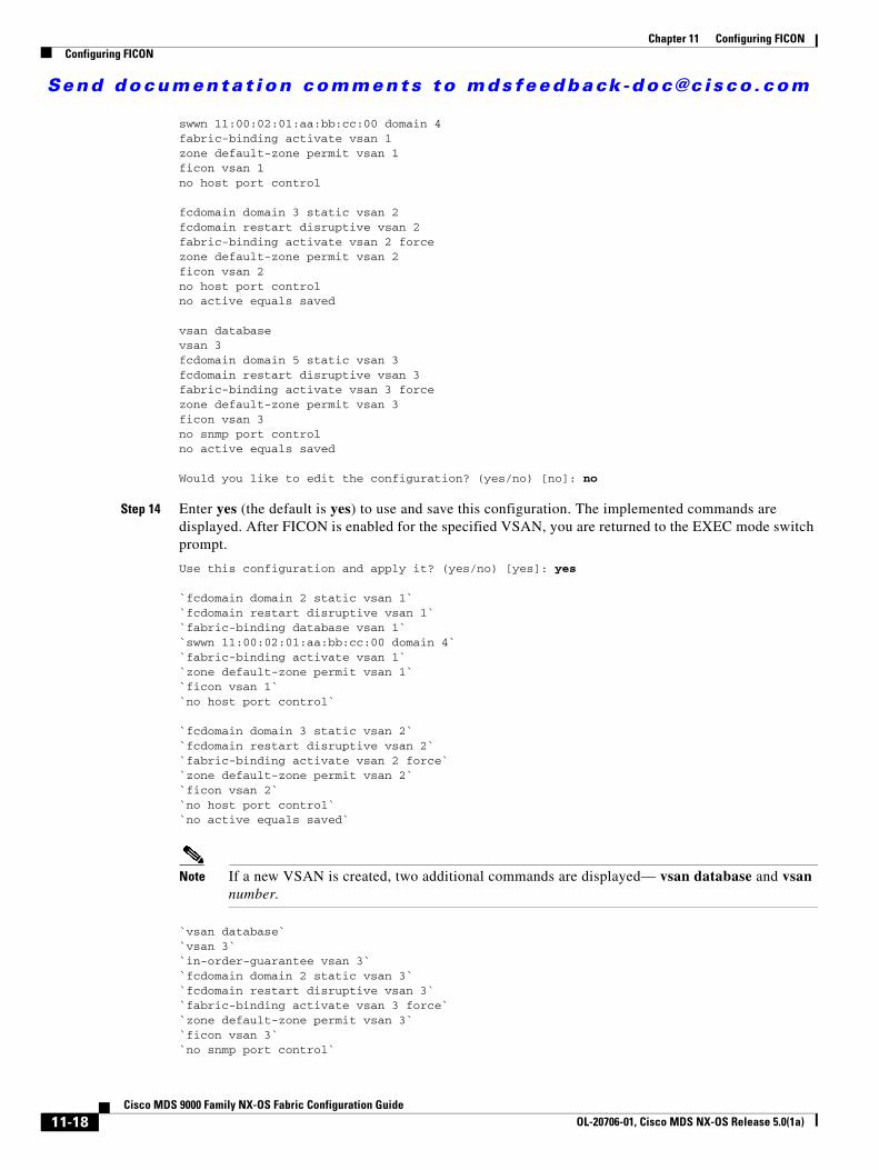
Send documenta t ion comments to mdsfeedback -doc@c i sco .com
Chapter 11 Configuring FICONConfiguring FICON
swwn 11:00:02:01:aa:bb:cc:00 domain 4fabric-binding activate vsan 1zone default-zone permit vsan 1ficon vsan 1no host port control
fcdomain domain 3 static vsan 2fcdomain restart disruptive vsan 2fabric-binding activate vsan 2 forcezone default-zone permit vsan 2ficon vsan 2no host port controlno active equals saved
vsan databasevsan 3fcdomain domain 5 static vsan 3fcdomain restart disruptive vsan 3fabric-binding activate vsan 3 forcezone default-zone permit vsan 3ficon vsan 3no snmp port controlno active equals saved
Would you like to edit the configuration? (yes/no) [no]: no
Step 14 Enter yes (the default is yes) to use and save this configuration. The implemented commands are displayed. After FICON is enabled for the specified VSAN, you are returned to the EXEC mode switch prompt.
Use this configuration and apply it? (yes/no) [yes]: yes
`fcdomain domain 2 static vsan 1``fcdomain restart disruptive vsan 1``fabric-binding database vsan 1``swwn 11:00:02:01:aa:bb:cc:00 domain 4``fabric-binding activate vsan 1``zone default-zone permit vsan 1``ficon vsan 1``no host port control`
`fcdomain domain 3 static vsan 2``fcdomain restart disruptive vsan 2``fabric-binding activate vsan 2 force``zone default-zone permit vsan 2``ficon vsan 2``no host port control``no active equals saved`
Note If a new VSAN is created, two additional commands are displayed— vsan database and vsan number.
`vsan database``vsan 3``in-order-guarantee vsan 3``fcdomain domain 2 static vsan 3``fcdomain restart disruptive vsan 3``fabric-binding activate vsan 3 force``zone default-zone permit vsan 3``ficon vsan 3``no snmp port control`
11-18Cisco MDS 9000 Family NX-OS Fabric Configuration Guide
OL-20706-01, Cisco MDS NX-OS Release 5.0(1a)

Send documenta t ion comments to mdsfeedback -doc@c i sco .com
Chapter 11 Configuring FICONConfiguring FICON
Performing fast copy config...done.switch#
Manually Enabling FICON on a VSAN
Note This section describes the procedure to manually enable FICON on a VSAN. If you have already enabled FICON on the required VSAN using the automated setup (recommended), skip to the “Automatically Saving the Running Configuration” section on page 11-22.
To manually enable FICON on a VSAN, follow these steps:
Command Purpose
Step 1 switch# config tswitch(config)#
Enters configuration mode.
Step 2 switch(config)# vsan databaseswitch(config-vsan-db)# vsan 5switch(config-vsan-db)# do show vsan usage4 vsan configuredconfigured vsans:1-2,5,26vsans available for configuration:3-4,6-25,27-4093switch(config-vsan-db)# exit
Enables VSAN 5.
Step 3 switch(config)# in-order-guarantee vsan 5 Activates in-order delivery for VSAN 5.
See Chapter 7, “Configuring Fibre Channel Routing Services and Protocols.”
Step 4 switch(config)# fcdomain domain 2 static vsan 2 Configures the domain ID for VSAN 2.
For information about configuring domain parameters, refer to the Cisco MDS 9000 Family NX-OS System Management Configuration Guide.
Step 5 switch(config)# fabric-binding activate vsan 2 force Activates fabric binding on VSAN 2.
Refer to the Cisco MDS 9000 Family NX-OS Security Configuration Guide
Step 6 switch(config)# zone default-zone permit vsan 2 Sets the default zone to permit for VSAN 2.
See the “CUP In-Band Management” section on page 11-42.
11-19Cisco MDS 9000 Family NX-OS Fabric Configuration Guide
OL-20706-01, Cisco MDS NX-OS Release 5.0(1a)

Send documenta t ion comments to mdsfeedback -doc@c i sco .com
Chapter 11 Configuring FICONConfiguring FICON
Configuring the code-page OptionFICON strings are coded in Extended Binary-Coded Decimal Interchange Code (EBCDIC) format. Refer to your mainframe documentation for details on the code page options.
Cisco MDS switches support international-5, france, brazil, germany, italy, japan, spain-latinamerica, uk, and us-canada (default) EBCDIC format options.
Tip This is an optional configuration. If you are not sure of the EBCDIC format to be used, we recommend retaining the us-canada (default) option.
To configure the code-page option in a VSAN, follow these steps:
Allowing the Host to Move the Switch OfflineBy default, hosts are allowed to move the switch to an offline state. To do this, the host sends a "Set offline" command (x'FD') to the CUP.
To allow the host to move the switch to an offline state, follow these steps:
Step 7 switch(config)# ficon vsan 2switch(config-ficon)#
Enables FICON on VSAN 2.
switch(config)# no ficon vsan 6 Disables the FICON feature on VSAN 6.
Step 8 switch(config-ficon)# no host port control Prohibits mainframe users from moving the switch to an offline state.
See the “Allowing the Host to Move the Switch Offline” section on page 11-20.
Command Purpose
Command Purpose
Step 1 switch# config tswitch(config)#
Enters configuration mode.
Step 2 switch(config)# ficon vsan 2switch(config-ficon)#
Enables FICON on VSAN 2.
Step 3 switch(config-ficon)# code-page italy Configures the italy EBCDIC format.
switch(config-ficon)# no code-page Reverts to the factory default of using the us-canada EBCDIC format.
Command Purpose
Step 1 switch# config tswitch(config)#
Enters configuration mode.
Step 2 switch(config)# ficon vsan 2switch(config-ficon)#
Enables FICON on VSAN 2.
Step 3 switch(config-ficon)# no host control switch offline
Prohibits mainframe users from moving the switch to an offline state.
switch(config-ficon)# host control switch offline
Allows the host to move the switch to an offline state (default) and shuts down the ports.
11-20Cisco MDS 9000 Family NX-OS Fabric Configuration Guide
OL-20706-01, Cisco MDS NX-OS Release 5.0(1a)

Send documenta t ion comments to mdsfeedback -doc@c i sco .com
Chapter 11 Configuring FICONConfiguring FICON
Allowing the Host to Change FICON Port ParametersBy default, mainframe users are not allowed to configure FICON parameters on Cisco MDS switches—they can only query the switch.
Use the host port control command to permit mainframe users to configure FICON parameters.
To allow the host (mainframe) to configure FICON parameters on the Cisco MDS switch, follow these steps:
Allowing the Host to Control the Timestamp By default, the clock in each VSAN is the same as the switch hardware clock. Each VSAN in a Cisco MDS 9000 Family switch represents a virtual director. The clock and time present in each virtual director can be different.To maintain separate clocks for each VSAN, the Cisco NX-OS software maintains the difference of the VSAN-specific clock and the hardware-based director clock. When a host (mainframe) sets the time, the Cisco NX-OS software updates this difference between the clocks. When a host reads the clock, it computes the difference between the VSAN-clock and the current director hardware clock and presents a value to the mainframe.
The VSAN-clock current time is reported in the output of show ficon vsan vsan-id, show ficon, and show accounting log commands.
To configure host control of the timestamp, follow these steps:
Clearing the Time Stamp
Note You can clear time stamps only from the Cisco MDS switch—not the mainframe.
Command Purpose
Step 1 switch# config tswitch(config)#
Enters configuration mode.
Step 2 switch(config)# ficon vsan 2switch(config-ficon)#
Enables FICON on VSAN 2.
Step 3 switch(config-ficon)# no host port control Prohibits mainframe users from configuring FICON parameters on the Cisco MDS switch.
switch(config-ficon)# host port control Allows mainframe users to configure FICON parameters on the Cisco MDS switch (default).
Command Purpose
Step 1 switch# config tswitch(config)#
Enters configuration mode.
Step 2 switch(config)# ficon vsan 2switch(config-ficon)#
Enables FICON on VSAN 2.
Step 3 switch(config-ficon)# no host set-timestamp
Prohibits mainframe users from changing the VSAN-specific clock.
switch(config-ficon)# host set-timestamp Allows the host to set the clock on this switch (default).
11-21Cisco MDS 9000 Family NX-OS Fabric Configuration Guide
OL-20706-01, Cisco MDS NX-OS Release 5.0(1a)

Send documenta t ion comments to mdsfeedback -doc@c i sco .com
Chapter 11 Configuring FICONConfiguring FICON
Use the clear ficon vsan vsan-id timestamp command in EXEC mode to clear the VSAN clock.
switch# clear ficon vsan 20 timestamp
Configuring SNMP Control of FICON ParametersBy default, SNMP users can configure FICON parameters through the Cisco MDS 9000 Family Fabric Manager.
Note If you disable SNMP in the Cisco MDS switch, you cannot configure FICON parameters using the Fabric Manager.
To configure SNMP control of FICON parameters, follow these steps:
About FICON Device AllegianceFICON requires serialization of access among multiple mainframes, CLI, and SNMP sessions be maintained on Cisco MDS 9000 Family switches by controlling device allegiance for the currently executing session. Any other session is denied permission to perform configuration changes unless the required allegiance is available.
Caution This task discards the currently executing session.
Clearing FICON Device AllegianceYou can clear the current device allegiance by issuing the clear ficon vsan vsan-id allegiance command in EXEC mode.
switch# clear ficon vsan 1 allegiance
Automatically Saving the Running ConfigurationCisco MDS NX-OS provides an option to automatically save any configuration changes to the startup configuration. This ensures that the new configuration is present after a switch reboot. The active equals saved option can be enabled on any FICON VSAN.
Command Purpose
Step 1 switch# config tswitch(config)#
Enters configuration mode.
Step 2 switch(config)# ficon vsan 2switch(config-ficon)#
Enables FICON on VSAN 2.
Step 3 switch(config-ficon)# no snmp port control
Prohibits SNMP users from configuring FICON parameters.
switch(config-ficon)# snmp port control Allows SNMP users to configure FICON parameters (default).
11-22Cisco MDS 9000 Family NX-OS Fabric Configuration Guide
OL-20706-01, Cisco MDS NX-OS Release 5.0(1a)

Send documenta t ion comments to mdsfeedback -doc@c i sco .com
Chapter 11 Configuring FICONConfiguring FICON
Table 11-2 displays the results of the Active = Saved option active equals saved command and the implicit copy from the running configuration to the startup configuration (copy running start)copy running-config startup-config command in various scenarios.
If the Active=Saved optionactive equals saved command is enabled in any FICON-enabled VSAN in the fabric, then the following apply (see Number 1 and 2 in Table 11-2):
• All configuration changes (FICON-specific or not) are automatically saved to persistent storage (implicit copy running start) and stored in the startup configuration.
• FICON-specific configuration changes are immediately saved to the IPL file (see the “FICON Configuration Files” section on page 11-32).
If the Active=Saved option active equals saved command is not enabled in any FICON-enabled VSAN in the fabric, then FICON-specific configuration changes are not saved in the IPL file and an implicit copy running startup command is not issued, you must explicitly save the running configuration to the startup configuration issue the copy running start command explicitly (see number 3 in Table 11-2).
Note If active equals saved is enabled, the Cisco NX-OS software ensures that you do not have to perform the copy running startup command for the FICON configuration as well. If your switch or fabric consists of multiple FICON-enabled VSANs, and one of these VSANs have active equals saved enabled, changes made to the non-FICON configuration results in all configurations being saved to the startup configuration.
To automatically save the running configuration, follow these steps:
Table 11-2 Saving the Active FICON and Switch Configuration
Number
FICON-enabled VSAN?
active equals saved
Enabled?
Implicit1 copy running start
Issued?
1. When the Cisco NX-OS software implicitly issues a copy running-config startup-config command in the Cisco MDS switch, only a binary configuration is generated—an ASCII configuration is not generated (see Example 11-24 on page 11-51). If you wish to generate an additional ASCII configuration at this stage, you must explicitly issue the copy running-config startup-config command again.
Notes
1 Yes Yes (in all FICON VSANs)
Implicit FICON changes written to the IPL file.
Non-FICON changes saved to startup configuration and persistent storage.
2 Yes Yes (even in one FICON VSAN)
Implicit FICON changes written to IPL file for only the VSAN that has active equals saved option enabled.
Non-FICON changes saved to startup configuration and persistent storage.
3 Yes Not in any FICON VSAN
Not implicit FICON changes are not written to the IPL file.
Non-FICON changes are saved in persistent storage—only if you explicitly issue the copy running start command.
4 No Not applicable
Command Purpose
Step 1 switch# config tswitch(config)#
Enters configuration mode.
Step 2 switch(config)# ficon vsan 2switch(config-ficon)#
Enables FICON on VSAN 2.
11-23Cisco MDS 9000 Family NX-OS Fabric Configuration Guide
OL-20706-01, Cisco MDS NX-OS Release 5.0(1a)

Send documenta t ion comments to mdsfeedback -doc@c i sco .com
Chapter 11 Configuring FICONConfiguring FICON Ports
Configuring FICON PortsYou can perform FICON configurations on a per-port address basis in the Cisco MDS 9000 Family switches.
Even if a port is uninstalled, the port address-based configuration is accepted by the Cisco MDS switch. This configuration is applied to the port when the port becomes installed.
This section includes the following topics:
• Binding Port Numbers to PortChannels, page 11-24
• Binding Port Numbers to FCIP Interfaces, page 11-24
• Configuring Port Blocking, page 11-25
• Port Prohibiting, page 11-25
• Assigning a Port Address Name, page 11-27
• About RLIR, page 11-27
• Specifying an RLIR Preferred Host, page 11-27
• Displaying RLIR Information, page 11-28
• Clearing RLIR Information, page 11-32
Binding Port Numbers to PortChannels
Caution All port number assignments to PortChannels or FCIP interfaces are lost (cannot be retrieved) when FICON is disabled on all VSANs.
You can bind (or associate) a PortChannel with a FICON port number to bring up that interface.
To bind a PortChannel with a FICON port number, follow these steps:
Binding Port Numbers to FCIP Interfaces You can bind (or associate) an FCIP interface with a FICON port number to bring up that interface.
Step 3 switch(config-ficon)# active equals saved Enables the automatic save feature for all VSANs in the switch or fabric.
switch(config-ficon)# no active equals saved Disables automatic save for this VSAN.
Command Purpose
Command Purpose
Step 1 switch# config tswitch(config)#
Enters configuration mode.
Step 2 switch(config)# interface Port-channel 1switch(config-if)#
Enters the PortChannel interface configuration mode.
Step 3 switch(config-if)# ficon portnumber 234 Assigns the FICON port number to the selected PortChannel port.
11-24Cisco MDS 9000 Family NX-OS Fabric Configuration Guide
OL-20706-01, Cisco MDS NX-OS Release 5.0(1a)
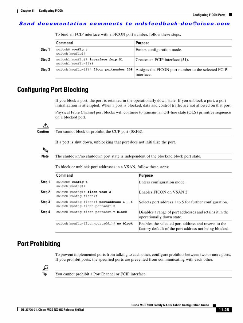
Send documenta t ion comments to mdsfeedback -doc@c i sco .com
Chapter 11 Configuring FICONConfiguring FICON Ports
To bind an FCIP interface with a FICON port number, follow these steps:
Configuring Port BlockingIf you block a port, the port is retained in the operationally down state. If you unblock a port, a port initialization is attempted. When a port is blocked, data and control traffic are not allowed on that port.
Physical Fibre Channel port blocks will continue to transmit an Off-line state (OLS) primitive sequence on a blocked port.
Caution You cannot block or prohibit the CUP port (0XFE).
If a port is shut down, unblocking that port does not initialize the port.
Note The shutdown/no shutdown port state is independent of the block/no block port state.
To block or unblock port addresses in a VSAN, follow these steps:
Port ProhibitingTo prevent implemented ports from talking to each other, configure prohibits between two or more ports. If you prohibit ports, the specified ports are prevented from communicating with each other.
Tip You cannot prohibit a PortChannel or FCIP interface.
Command Purpose
Step 1 switch# config tswitch(config)#
Enters configuration mode.
Step 2 switch1(config)# interface fcip 51switch1(config-if)#
Creates an FCIP interface (51).
Step 3 switch(config-if)# ficon portnumber 208 Assigns the FICON port number to the selected FCIP interface.
Command Purpose
Step 1 switch# config tswitch(config)#
Enters configuration mode.
Step 2 switch(config)# ficon vsan 2switch(config-ficon)#
Enables FICON on VSAN 2.
Step 3 switch(config-ficon)# portaddress 1 - 5 switch(config-ficon-portaddr)#
Selects port address 1 to 5 for further configuration.
Step 4 switch(config-ficon-portaddr)# block Disables a range of port addresses and retains it in the operationally down state.
switch(config-ficon-portaddr)# no block Enables the selected port address and reverts to the factory default of the port address not being blocked.
11-25Cisco MDS 9000 Family NX-OS Fabric Configuration Guide
OL-20706-01, Cisco MDS NX-OS Release 5.0(1a)
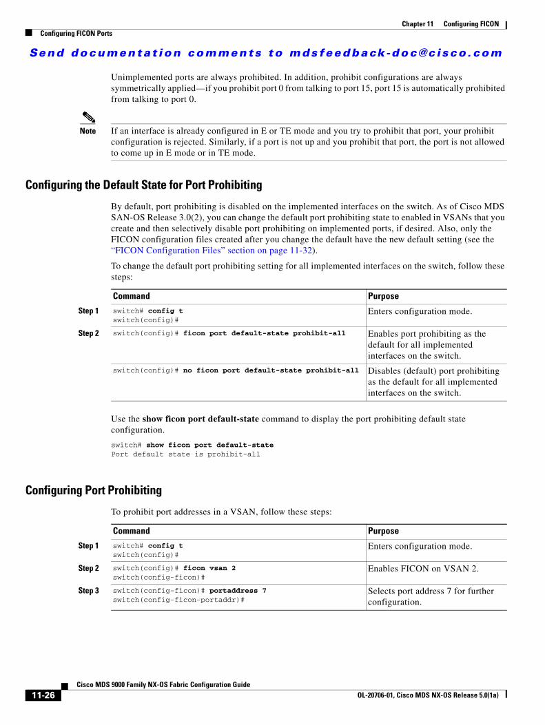
Send documenta t ion comments to mdsfeedback -doc@c i sco .com
Chapter 11 Configuring FICONConfiguring FICON Ports
Unimplemented ports are always prohibited. In addition, prohibit configurations are always symmetrically applied—if you prohibit port 0 from talking to port 15, port 15 is automatically prohibited from talking to port 0.
Note If an interface is already configured in E or TE mode and you try to prohibit that port, your prohibit configuration is rejected. Similarly, if a port is not up and you prohibit that port, the port is not allowed to come up in E mode or in TE mode.
Configuring the Default State for Port Prohibiting
By default, port prohibiting is disabled on the implemented interfaces on the switch. As of Cisco MDS SAN-OS Release 3.0(2), you can change the default port prohibiting state to enabled in VSANs that you create and then selectively disable port prohibiting on implemented ports, if desired. Also, only the FICON configuration files created after you change the default have the new default setting (see the “FICON Configuration Files” section on page 11-32).
To change the default port prohibiting setting for all implemented interfaces on the switch, follow these steps:
Use the show ficon port default-state command to display the port prohibiting default state configuration.
switch# show ficon port default-statePort default state is prohibit-all
Configuring Port Prohibiting
To prohibit port addresses in a VSAN, follow these steps:
Command Purpose
Step 1 switch# config tswitch(config)#
Enters configuration mode.
Step 2 switch(config)# ficon port default-state prohibit-all Enables port prohibiting as the default for all implemented interfaces on the switch.
switch(config)# no ficon port default-state prohibit-all Disables (default) port prohibiting as the default for all implemented interfaces on the switch.
Command Purpose
Step 1 switch# config tswitch(config)#
Enters configuration mode.
Step 2 switch(config)# ficon vsan 2switch(config-ficon)#
Enables FICON on VSAN 2.
Step 3 switch(config-ficon)# portaddress 7switch(config-ficon-portaddr)#
Selects port address 7 for further configuration.
11-26Cisco MDS 9000 Family NX-OS Fabric Configuration Guide
OL-20706-01, Cisco MDS NX-OS Release 5.0(1a)

Send documenta t ion comments to mdsfeedback -doc@c i sco .com
Chapter 11 Configuring FICONConfiguring FICON Ports
Assigning a Port Address NameTo assign a port address name, follow these steps:
About RLIRThe Registered Link Incident Report (RLIR) application provides a method for a switch port to send an Link Incident Record (LIR) to a registered Nx port.
When an LIR is detected in FICON-enabled switches in the Cisco MDS 9000 Family from a RLIR Extended Link Service (ELS), the switch sends that record to the members in its Established Registration List (ERL).
In case of multiswitch topology, a Distribute Registered Link Incident Record (DRLIR) Inter-Link Service (ILS) is sent to all reachable remote domains along with the RLIR ELS. On receiving the DRLIR ILS, the switch extracts the RLIR ELS and sends it to the members of the ERL.
The Nx ports interested in receiving the RLIR ELS send the Link Incident Record Registration (LIRR) ELS request to the management server on the switch. The RLIRs are processed on a per-VSAN basis.
The RLIR data is written to persistent storage when you enter the copy running-config startup-config command.
Specifying an RLIR Preferred HostAs of Cisco MDS SAN-OS Release 3.0(3), you can specify a preferred host to receive RLIR frames. The MDS switch sends RLIR frames to the preferred host only if it meets the following conditions:
• No host in the VSAN is registered for RLIR with the registration function set to “always receive.” If one or more hosts in the VSAN are registered as “always receive,” then RLIR sends only to these hosts and not to the configured preferred host.
Step 4 switch(config-ficon-portaddr)# prohibit portaddress 3-5 Prohibits port address 7 in VSAN 2 from talking to ports 3, 4, and 5.
switch(config-ficon-portaddr)# no prohibit portaddress 5 Removes port address 5 from a previously prohibited state.
Command Purpose
Command Purpose
Step 1 switch# config tswitch(config)#
Enters configuration mode.
Step 2 switch(config)# ficon vsan 2switch(config-ficon)#
Enables FICON on VSAN 2.
Step 3 switch(config-ficon)# portaddress 7 switch(config-ficon-portaddr)#
Selects port address 7 for further configuration.
Step 4 switch(config-ficon-portaddr)# name SampleName Assigns a name to the port address.
Note The port address name is restricted to 24 alphanumeric characters.
switch(config-ficon-portaddr)# no name SampleName Deletes a previously configured port address name.
11-27Cisco MDS 9000 Family NX-OS Fabric Configuration Guide
OL-20706-01, Cisco MDS NX-OS Release 5.0(1a)

Send documenta t ion comments to mdsfeedback -doc@c i sco .com
Chapter 11 Configuring FICONConfiguring FICON Ports
• The preferred host is registered with the registration function set to “conditionally receive.”
Note If all registered hosts have the registration function set to “conditionally receive,” then the preferred host receives the RLIR frames.
You can specify only one RLIR preferred host per VSAN. By default, the switch sends RLIR frames to one of the hosts in the VSAN with the register function set to “conditionally receive” if no hosts have the register function set to “always receive.”
To specify the RLIR preferred host for a VSAN, follow these steps:
To display the RLIR preferred host configuration, use the show rlir erl command.
switch# show rlir erlEstablished Registration List for VSAN: 5----------------------------------------------FC-ID LIRR FORMAT REGISTERED FOR----------------------------------------------0x772c00 0x18 conditional receive(*)0x779600 0x18 conditional receive0x779700 0x18 conditional receive0x779800 0x18 conditional receiveTotal number of entries = 4(*) - Denotes the preferred host
Displaying RLIR InformationThe show rlir statistics command displays the complete statistics of LIRR, RLIR, and DRLIR frames. It lists the number of frames received, sent, and rejected. Specify the VSAN ID to obtain VSAN statistics for a specific VSAN. If you do not specify the VSAN ID, then the statistics are shown for all active VSANs (see Examples 11-1 and 11-2).
Example 11-1 Displays RLIR Statistics for All VSANs
switch# show rlir statistics
Statistics for VSAN: 1------------------------
Number of LIRR received = 0Number of LIRR ACC sent = 0Number of LIRR RJT sent = 0Number of RLIR sent = 0Number of RLIR ACC received = 0Number of RLIR RJT received = 0
Command Purpose
Step 1 switch# config tswitch(config)#
Enters configuration mode.
Step 2 switch(config)# rlir preferred-cond fcid 0x772c00 vsan 5
Specifies FC ID 0x772c00 as the RLIR preferred host in VSAN 5. (FC ID 0x772c00 is used here as an example.)
switch(config)# no rlir preferred-cond fcid 0x654321 vsan 2
Removes FC ID 0x772c00 as the RLIR preferred host for VSAN 5.
11-28Cisco MDS 9000 Family NX-OS Fabric Configuration Guide
OL-20706-01, Cisco MDS NX-OS Release 5.0(1a)

Send documenta t ion comments to mdsfeedback -doc@c i sco .com
Chapter 11 Configuring FICONConfiguring FICON Ports
Number of DRLIR received = 0Number of DRLIR ACC sent = 0Number of DRLIR RJT sent = 0Number of DRLIR sent = 0Number of DRLIR ACC received = 0Number of DRLIR RJT received = 0
Statistics for VSAN: 100-------------------------
Number of LIRR received = 26Number of LIRR ACC sent = 26Number of LIRR RJT sent = 0Number of RLIR sent = 815Number of RLIR ACC received = 815Number of RLIR RJT received = 0Number of DRLIR received = 417Number of DRLIR ACC sent = 417Number of DRLIR RJT sent = 0Number of DRLIR sent = 914Number of DRLIR ACC received = 828Number of DRLIR RJT received = 0
Example 11-2 Displays RLIR Statistics for a Specified VSAN
switch# show rlir statistics vsan 4
Statistics for VSAN: 4-------------------------
Number of LIRR received = 0Number of LIRR ACC sent = 0Number of LIRR RJT sent = 0Number of RLIR sent = 0Number of RLIR ACC received = 0Number of RLIR RJT received = 0Number of DRLIR received = 0Number of DRLIR ACC sent = 0Number of DRLIR RJT sent = 0Number of DRLIR sent = 0Number of DRLIR ACC received = 0Number of DRLIR RJT received = 0
The show rlir erl command shows the list of Nx ports that are registered to receive the RLIRs with the switch. If the VSAN ID is not specified, the details are shown for all active VSANs (see Examples 11-3 and 11-4).
Example 11-3 Displays All ERLs
switch# show rlir erl
Established Registration List for VSAN: 2----------------------------------------------FC-ID LIRR FORMAT REGISTERED FOR----------------------------------------------0x0b0200 0x18 always receiveTotal number of entries = 1
Established Registration List for VSAN: 100----------------------------------------------FC-ID LIRR FORMAT REGISTERED FOR----------------------------------------------
11-29Cisco MDS 9000 Family NX-OS Fabric Configuration Guide
OL-20706-01, Cisco MDS NX-OS Release 5.0(1a)

Send documenta t ion comments to mdsfeedback -doc@c i sco .com
Chapter 11 Configuring FICONConfiguring FICON Ports
0x0b0500 0x18 conditional receive0x0b0600 0x18 conditional receiveTotal number of entries = 2
In Example 11-3, if the Registered For column states that an FC ID is conditional receive, the source port is registered as a valid recipient of subsequent RLIRs. This source port is selected as an RLIR recipient only if no other ERL recipient is selected.
In Example 11-3, if the Registered For column states that an FC ID is always receive, the source port is registered as a valid recipient of subsequent RLIRs. This source port is always selected as an LIR recipient.
Note If an always receive RLIR is not registered for any N port or if the delivery of an RLIR fails for one of those ports, then the RLIR is sent to a port registered to conditional receive RLIRs.
Example 11-4 Displays ERLs for the Specified VSAN
switch# show rlir erl vsan 100Established Registration List for VSAN: 100----------------------------------------------FC-ID LIRR FORMAT REGISTERED FOR----------------------------------------------0x0b0500 0x18 conditional receive0x0b0600 0x18 conditional receive
Total number of entries = 2
Note In Example 11-5, through Example 11-7, if the host time stamp (marked by the *) is available, it is printed along with the switch time stamp. If the host time stamp is not available, only the switch time stamp is printed.
Example 11-5 Displays the LIR History
switch# show rlir history
Link incident history----------------------------------------------------------------------------*Host Time Stamp Switch Time Stamp Port Interface Link Incident----------------------------------------------------------------------------
*Sun Nov 30 21:47:28 2003 Sun Nov 30 13:47:55 2003 2 fc1/2 Implicit Incident*Sun Nov 30 22:00:47 2003 Sun Nov 30 14:01:14 2003 2 fc1/2 NOS Received*Sun Nov 30 22:00:55 2003 Sun Nov 30 14:01:22 2003 2 fc1/2 Implicit Incident*Mon Dec 1 20:14:26 2003 Mon Dec 1 12:14:53 2003 4 fc1/4 Implicit Incident*Mon Dec 1 20:14:26 2003 Mon Dec 1 12:14:53 2003 4 fc1/4 Implicit Incident*Thu Dec 4 04:43:32 2003 Wed Dec 3 20:43:59 2003 2 fc1/2 NOS Received*Thu Dec 4 04:43:41 2003 Wed Dec 3 20:44:08 2003 2 fc1/2 Implicit Incident*Thu Dec 4 04:46:53 2003 Wed Dec 3 20:47:20 2003 2 fc1/2 NOS Received
11-30Cisco MDS 9000 Family NX-OS Fabric Configuration Guide
OL-20706-01, Cisco MDS NX-OS Release 5.0(1a)

Send documenta t ion comments to mdsfeedback -doc@c i sco .com
Chapter 11 Configuring FICONConfiguring FICON Ports
*Thu Dec 4 04:47:05 2003 Wed Dec 3 20:47:32 2003 2 fc1/2 Implicit Incident*Thu Dec 4 04:48:07 2003 Wed Dec 3 20:48:34 2003 2 fc1/2 NOS Received*Thu Dec 4 04:48:39 2003 Wed Dec 3 20:49:06 2003 2 fc1/2 Implicit Incident*Thu Dec 4 05:02:20 2003 Wed Dec 3 21:02:47 2003 2 fc1/2 NOS Received...
Example 11-6 Displays Recent LIRs for a Specified Interface
switch# show rlir recent interface fc1/1-4
Recent link incident records-------------------------------------------------------------------------------Host Time Stamp Switch Time Stamp Port Intf Link Incident-------------------------------------------------------------------------------Thu Dec 4 05:02:29 2003 Wed Dec 3 21:02:56 2003 2 fc1/2 Implicit IncidentThu Dec 4 05:02:54 2003 Wed Dec 3 21:03:21 2003 4 fc1/4 Implicit Incident
Example 11-7 Displays Recent LIRs for a Specified Port Number
switch# show rlir recent portnumber 1-4
Recent link incident records--------------------------------------------------------------------------------Host Time Stamp Switch Time Stamp Port Intf Link Incident--------------------------------------------------------------------------------Thu Dec 4 05:02:29 2003 Wed Dec 3 21:02:56 2003 2 fc1/2 Implicit IncidentThu Dec 4 05:02:54 2003 Wed Dec 3 21:03:21 2003 4 fc1/4 Implicit Incident
As of Cisco SAN-OS Release 3.0(3), the show rlir history command output includes remote link incidents that are received as DRLIRs from other switches. RLIRs are generated as a result of DRLIRs as in previous Cisco NX-OS releases (see Example 11-8).
Example 11-8 Displays the LIR History as of Cisco SAN-OS Release 3.0(3)
switch# show rlir history
Link incident history---------------------------------------------------------------------------------------------------------------- Host Time Stamp Switch Time Stamp VSAN Domain Port Intf Link Incident Loc/Rem---------------------------------------------------------------------------------------------------------------- Sep 20 12:42:44 2006 Sep 20 12:42:44 2006 **** **** 0x0b fc1/12 Loss of sig/sync LOC Reported Successfully to: [0x640001] [0x640201] Sep 20 12:42:48 2006 Sep 20 12:42:48 2006 **** **** 0x0b fc1/12 Loss of sig/sync LOC Reported Successfully to: [0x640001] [0x640201] *** ** **:**:** **** Sep 20 12:42:51 2006 1001 230 0x12 **** Loss of sig/sync REM Reported Successfully to: [0x640001] [0x640201] Sep 20 12:42:55 2006 Sep 20 12:42:55 2006 **** **** 0x0b fc1/12 Loss of sig/sync LOC Reported Successfully to: None [No Registrations] *** ** **:**:** **** Sep 20 12:45:56 2006 1001 230 0x12 **** Loss of sig/sync REM Reported Successfully to: None [No Registrations] *** ** **:**:** **** Sep 20 12:45:56 2006 1001 230 0x12 **** Loss of sig/sync REM Reported Successfully to: None [No Registrations]
11-31Cisco MDS 9000 Family NX-OS Fabric Configuration Guide
OL-20706-01, Cisco MDS NX-OS Release 5.0(1a)

Send documenta t ion comments to mdsfeedback -doc@c i sco .com
Chapter 11 Configuring FICONFICON Configuration Files
Sep 20 12:52:45 2006 Sep 20 12:52:45 2006 **** **** 0x0b fc1/12 Loss of sig/sync LOC Reported Successfully to: None [No Registrations]
**** - Info not required/unavailable
Clearing RLIR InformationUse the clear rlir statistics command to clear all existing statistics for a specified VSAN.
switch# clear rlir statistics vsan 1
Use the clear rlir history command to clear the RLIR history where all link incident records are logged for all interfaces.
switch# clear rlir history
Use the clear rlir recent interface command to clear the most recent RLIR information for a specified interface.
switch# clear rlir recent interface fc 1/2
Use the clear rlir recent portnumber command to clear the most recent RLIR information for a specified port number.
switch# clear rlir recent portnumber 16
FICON Configuration FilesYou can save up to 16 FICON configuration files on each FICON-enabled VSAN (in persistent storage). The file format is proprietary to IBM. These files can be read and written by IBM hosts using the in-band CUP protocol. Additionally, you can use the Cisco MDS CLI or Fabric Manager applications to operate on these FICON configuration files.
Note Multiple FICON configuration files with the same name can exist in the same switch, provided they reside in different VSANs. For example, you can create a configuration file named XYZ in both VSAN 1 and VSAN 3.
When you enable the FICON feature in a VSAN, the switches always use the startup FICON configuration file, called IPL. This file is created with a default configuration as soon as FICON is enabled in a VSAN.
Caution When FICON is disabled on a VSAN, all the FICON configuration files are irretrievably lost.
FICON configuration files contain the following configuration for each implemented port address:
• Block
• Prohibit mask
• Port address name
11-32Cisco MDS 9000 Family NX-OS Fabric Configuration Guide
OL-20706-01, Cisco MDS NX-OS Release 5.0(1a)

Send documenta t ion comments to mdsfeedback -doc@c i sco .com
Chapter 11 Configuring FICONFICON Configuration Files
Note Normal configuration files used by Cisco MDS switches include FICON-enabled attributes for a VSAN, port number mapping for PortChannels and FCIP interfaces, port number to port address mapping, port and trunk allowed VSAN configuration for ports, in-order guarantee, static domain ID configuration, and fabric binding configuration.
Refer to the Cisco MDS 9000 Family NX-OS Fundamentals Configuration Guide for details on the normal configuration files used by Cisco MDS switches.
This section includes the following topics:
• About FICON Configuration Files, page 11-33
• Applying the Saved Configuration Files to the Running Configuration, page 11-33
• Editing FICON Configuration Files, page 11-33
• Displaying FICON Configuration Files, page 11-34
• Copying FICON Configuration Files, page 11-35
About FICON Configuration FilesOnly one user can access the configuration file at any given time:
• If this file is being accessed by user 1, user 2 cannot access this file.
• If user 2 does attempt to access this file, an error is issued to user 2.
• If user 1 is inactive for more than 15 seconds, the file is automatically closed and available for use by any other permitted user.
FICON configuration files can be accessed by any host, SNMP, or CLI user who is permitted to access the switch. The locking mechanism in the Cisco NX-OS software restricts access to one user at a time per file. This lock applies to newly created files and previously saved files. Before accessing any file, you must lock the file and obtain the file key. A new file key is used by the locking mechanism for each lock request. The key is discarded when the lock timeout of 15 seconds expires. The lock timeout value cannot be changed.
Applying the Saved Configuration Files to the Running ConfigurationYou can apply the configuration from the saved files to the running configuration using the ficon vsan number apply file filename command.
switch# ficon vsan 2 apply file SampleFile
Editing FICON Configuration FilesThe configuration file submode allows you to create and edit FICON configuration files. If a specified file does not exist, it is created. Up to 16 files can be saved. Each file name is restricted to eight alphanumeric characters.
11-33Cisco MDS 9000 Family NX-OS Fabric Configuration Guide
OL-20706-01, Cisco MDS NX-OS Release 5.0(1a)

Send documenta t ion comments to mdsfeedback -doc@c i sco .com
Chapter 11 Configuring FICONFICON Configuration Files
To edit the contents of a specified FICON configuration file, follow these steps:
Displaying FICON Configuration FilesUse the show ficon vsan vsan-id file all command to display the contents of all FICON configuration files.
switch# show ficon vsan 2 file allFile IPL is lockedFICON configuration file IPLFILEA in vsan 2Description: Port address 0(0) Port name is Port is not blocked Prohibited port addresses are 250-253,255(0xfa-0xfd,0xff)
Port address 1(0x1) Port name is Port is not blocked Prohibited port addresses are 250-253,255(0xfa-0xfd,0xff)Port address 2(0x2) Port name is
Command Purpose
Step 1 switch# config tswitch(config)#
Enters configuration mode.
Step 2 switch(config)# ficon vsan 2switch(config-ficon)#
Enables FICON on VSAN 2.
Step 3 switch(config-ficon)# file IplFile1switch(config-ficon-file)#
Accesses the FICON configuration file called IplFile1 for VSAN 2. If this file does not exist, it is created.
Note All FICON file names are restricted to eight alphanumeric characters.
switch(config-ficon)# no file IplFileA Deletes a previously created FICON configuration file.
Step 4 switch(config-ficon-file)# portaddress 3switch(config-ficon-file-portaddr)#
Enters the submode for port address 3 to edit the contents of the configuration file named IplFile1.
Note The running configuration is not applied to the current configuration. The configuration is only applied when the ficon vsan number apply file filename command is issued.
Step 5 switch(config-ficon-file-portaddr)# prohibit portaddress 5
Edits the content of the configuration file named IplFile1 by prohibiting port address 5 from accessing port address 3.
Step 6 switch(config-ficon-file-portaddr)# block Edits the content of the configuration file named IplFile1 by blocking a range of port addresses and retaining them in the operationally down state.
Step 7 switch(config-ficon-file-portaddr)# name P3 Edits the content of the configuration file named IplFile1 by assigning the name P3 to port address 3. If the name did not exist, it is created. If it existed, it is overwritten.
11-34Cisco MDS 9000 Family NX-OS Fabric Configuration Guide
OL-20706-01, Cisco MDS NX-OS Release 5.0(1a)

Send documenta t ion comments to mdsfeedback -doc@c i sco .com
Chapter 11 Configuring FICONFICON Configuration Files
Port is not blocked Prohibited port addresses are 250-253,255(0xfa-0xfd,0xff)
Port address 3(0x3) Port name is P3 Port is blocked Prohibited port addresses are 5,250-253,255(0x5,0xfa-0xfd,0xff)..
Use the show ficon vsan vsan-id file name command to display the contents of a specific FICON configuration file.
switch# show ficon vsan 2 file name IPLfileaFICON configuration file IPLFILEA in vsan 2Description: Port address 0(0) Port name is Port is not blocked Prohibited port addresses are 250-253,255(0xfa-0xfd,0xff)
Port address 1(0x1) Port name is Port is not blocked Prohibited port addresses are 250-253,255(0xfa-0xfd,0xff)
Port address 2(0x2) Port name is Port is not blocked Prohibited port addresses are 250-253,255(0xfa-0xfd,0xff)
Port address 3(0x3) Port name is P3 Port is blocked Prohibited port addresses are 5,250-253,255(0x5,0xfa-0xfd,0xff)
Use the show ficon vsan vsan-id file name filename portaddress command to display the FICON configuration file information for a specific FICON port.
switch# show ficon vsan 2 file name IPLfilea portaddress 3FICON configuration file IPLFILEA in vsan 2Description: Port address 3(0x3) Port name is P3 Port is blocked Prohibited port addresses are 5,250-253,255(0x5,0xfa-0xfd,0xff)
Copying FICON Configuration FilesUse the ficon vsan vsan-id copy file existing-file-name save-as-file-name command in EXEC mode to copy an existing FICON configuration file.
switch# ficon vsan 20 copy file IPL IPL3
You can see the list of existing configuration files by issuing the show ficon vsan vsan-id command.
switch# show ficon vsan 20Ficon information for VSAN 20 Ficon is online VSAN is active Host port control is Enabled
11-35Cisco MDS 9000 Family NX-OS Fabric Configuration Guide
OL-20706-01, Cisco MDS NX-OS Release 5.0(1a)
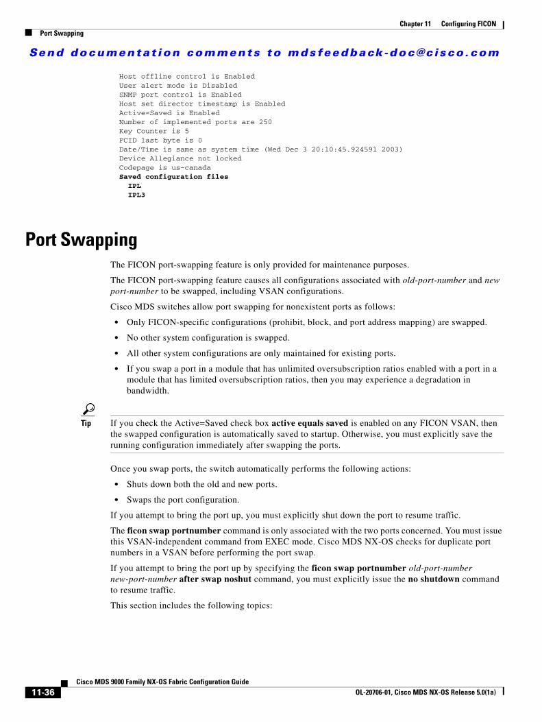
Send documenta t ion comments to mdsfeedback -doc@c i sco .com
Chapter 11 Configuring FICONPort Swapping
Host offline control is Enabled User alert mode is Disabled SNMP port control is Enabled Host set director timestamp is Enabled Active=Saved is Enabled Number of implemented ports are 250 Key Counter is 5 FCID last byte is 0 Date/Time is same as system time (Wed Dec 3 20:10:45.924591 2003) Device Allegiance not locked Codepage is us-canada Saved configuration files IPL IPL3
Port Swapping The FICON port-swapping feature is only provided for maintenance purposes.
The FICON port-swapping feature causes all configurations associated with old-port-number and new port-number to be swapped, including VSAN configurations.
Cisco MDS switches allow port swapping for nonexistent ports as follows:
• Only FICON-specific configurations (prohibit, block, and port address mapping) are swapped.
• No other system configuration is swapped.
• All other system configurations are only maintained for existing ports.
• If you swap a port in a module that has unlimited oversubscription ratios enabled with a port in a module that has limited oversubscription ratios, then you may experience a degradation in bandwidth.
Tip If you check the Active=Saved check box active equals saved is enabled on any FICON VSAN, then the swapped configuration is automatically saved to startup. Otherwise, you must explicitly save the running configuration immediately after swapping the ports.
Once you swap ports, the switch automatically performs the following actions:
• Shuts down both the old and new ports.
• Swaps the port configuration.
If you attempt to bring the port up, you must explicitly shut down the port to resume traffic.
The ficon swap portnumber command is only associated with the two ports concerned. You must issue this VSAN-independent command from EXEC mode. Cisco MDS NX-OS checks for duplicate port numbers in a VSAN before performing the port swap.
If you attempt to bring the port up by specifying the ficon swap portnumber old-port-number new-port-number after swap noshut command, you must explicitly issue the no shutdown command to resume traffic.
This section includes the following topics:
11-36Cisco MDS 9000 Family NX-OS Fabric Configuration Guide
OL-20706-01, Cisco MDS NX-OS Release 5.0(1a)
Send documenta t ion comments to mdsfeedback -doc@c i sco .com
Chapter 11 Configuring FICONPort Swapping
• About Port Swapping, page 11-37
• Swapping Ports, page 11-37
About Port SwappingBe sure to follow these guidelines when using the FICON port swapping feature:
• Port swapping is not supported for logical ports (PortChannels, FCIP links). Neither the old-port-number nor the new-port-number can be a logical port.
• Port swapping is not supported between physical ports that are part of a PortChannel. Neither the old-port-number nor the new-port-number can be a physical port that is part of a PortChannel.
• Before performing a port swap, the Cisco NX-OS software performs a compatibility check. If the two ports have incompatible configurations, the port swap is rejected with an appropriate reason code. For example, if a port with BB_credits as 25 is being swapped with an OSM port for which a maximum of 12 BB_credits is allowed (not a configurable parameter), the port swapping operation is rejected.
• Before performing a port swap, the Cisco NX-OS software performs a compatibility check to verify the extended BB_credits configuration.
• If ports have default values (for some incompatible parameters), then a port swap operation is allowed and the ports retain their default values.
• Port tracking information is not included in port swapping. This information must be configured separately (refer to the Cisco MDS 9000 Family NX-OS Quality of Service Configuration Guide).
Note The 32-port module guidelines also apply for port swapping configurations (Refer to the Cisco MDS 9000 Family NX-OS Interfaces Configuration Guide).
Swapping PortsIf there are no duplicate port numbers on the switch, you can swap physical Fibre Channel ports, except the port numbers, by following these steps:
Step 1 Issue the ficon swap portnumber old-port-number new-port-number command in EXEC mode.
Note The ficon swap portnumber command might fail if more than one interface on the MDS switch has the same port number as the old-port-number or new-port-number specified in the command.
The specified ports are operationally shut down.
Step 2 Physically swap the front panel port cables between the two ports.
Step 3 Issue the no shutdown command on each port to enable traffic flow.
11-37Cisco MDS 9000 Family NX-OS Fabric Configuration Guide
OL-20706-01, Cisco MDS NX-OS Release 5.0(1a)

Send documenta t ion comments to mdsfeedback -doc@c i sco .com
Chapter 11 Configuring FICONFICON Tape Acceleration
Note If you specify the ficon swap portnumber old-port-number new-port-number after swap noshut command, the ports are automatically initialized.
If there are duplicate port numbers on the switch, you can swap physical Fibre Channel ports, including the port numbers, by following these steps:
Step 1 Issue the ficon swap interface old-interface new-interface command in EXEC mode.
The specified interfaces are operationally shut down.
Step 2 Physically swap the front panel port cables between the two ports.
Step 3 Issue the no shutdown command on each port to enable traffic flow.
Note If you specify the ficon swap interface old-interface new-interface after swap noshut command, the ports are automatically initialized.
FICON Tape AccelerationThe sequential nature of tape devices causes each I/O operation to the tape device over an FCIP link to incur the latency of the FCIP link. Throughput drastically decreases as the round-trip time through the FCIP link increases, leading to longer backup windows. Also, after each I/O operation, the tape device is idle until the next I/O arrives. Starting and stopping of the tape head reduces the lifespan of the tape, except when I/O operations are directed to a virtual tape.
Cisco MDS NX-OS software provides acceleration for the following FICON tape write operations:
• The link between mainframe and native tape drives (both IBM and Sun/STK)
• The back-end link between the VSM (Virtual Storage Management) and tape drive (Sun/STK)
FICON tape acceleration over FCIP provides the following advantages:
• Efficiently utilizes the tape device by decreasing idle time
• More sustained throughput as latency increases
• Similar to FCP tape acceleration, and does not conflict with it
Note FICON tape read acceleration over FCIP is supported from Cisco MDS NX-OS Release 5.0(1). For more information refer to the “Configuring FICON Tape Read Acceleration” section on page 11-41.
Figure 11-5 through Figure 11-8 show supported configurations:
11-38Cisco MDS 9000 Family NX-OS Fabric Configuration Guide
OL-20706-01, Cisco MDS NX-OS Release 5.0(1a)
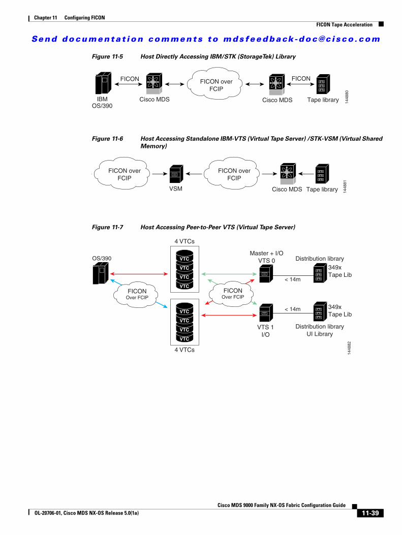
Send documenta t ion comments to mdsfeedback -doc@c i sco .com
Chapter 11 Configuring FICONFICON Tape Acceleration
Figure 11-5 Host Directly Accessing IBM/STK (StorageTek) Library
Figure 11-6 Host Accessing Standalone IBM-VTS (Virtual Tape Server) /STK-VSM (Virtual Shared
Memory)
Figure 11-7 Host Accessing Peer-to-Peer VTS (Virtual Tape Server)
IBMOS/390
Tape library
FICON
Cisco MDS Cisco MDS
FICON overFCIP
1448
80
FICON
Tape library
FICON overFCIP
FICON overFCIP
1448
81
VSM Cisco MDS
VTS 1I/O
Master + I/OVTS 0
FICONOver FCIP
FICONOver FCIP
< 14m
< 14m
OS/390
349xTape Lib
349xTape Lib
Distribution libraryUI Library
Distribution library
1448
82
VTC
VTC
VTC
VTC
VTC
VTC
VTC
VTC
4 VTCs
4 VTCs
11-39Cisco MDS 9000 Family NX-OS Fabric Configuration Guide
OL-20706-01, Cisco MDS NX-OS Release 5.0(1a)
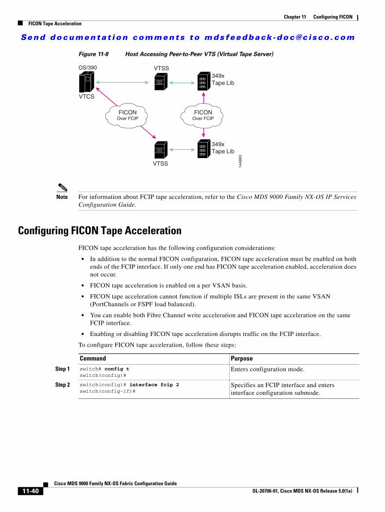
Send documenta t ion comments to mdsfeedback -doc@c i sco .com
Chapter 11 Configuring FICONFICON Tape Acceleration
Figure 11-8 Host Accessing Peer-to-Peer VTS (Virtual Tape Server)
Note For information about FCIP tape acceleration, refer to the Cisco MDS 9000 Family NX-OS IP Services Configuration Guide.
Configuring FICON Tape AccelerationFICON tape acceleration has the following configuration considerations:
• In addition to the normal FICON configuration, FICON tape acceleration must be enabled on both ends of the FCIP interface. If only one end has FICON tape acceleration enabled, acceleration does not occur.
• FICON tape acceleration is enabled on a per VSAN basis.
• FICON tape acceleration cannot function if multiple ISLs are present in the same VSAN (PortChannels or FSPF load balanced).
• You can enable both Fibre Channel write acceleration and FICON tape acceleration on the same FCIP interface.
• Enabling or disabling FICON tape acceleration disrupts traffic on the FCIP interface.
To configure FICON tape acceleration, follow these steps:
VTSS
VTSS
FICONOver FCIP
FICONOver FCIP
OS/390
349xTape Lib
349xTape Lib
VTCS
1448
83
Command Purpose
Step 1 switch# config tswitch(config)#
Enters configuration mode.
Step 2 switch(config)# interface fcip 2switch(config-if)#
Specifies an FCIP interface and enters interface configuration submode.
11-40Cisco MDS 9000 Family NX-OS Fabric Configuration Guide
OL-20706-01, Cisco MDS NX-OS Release 5.0(1a)
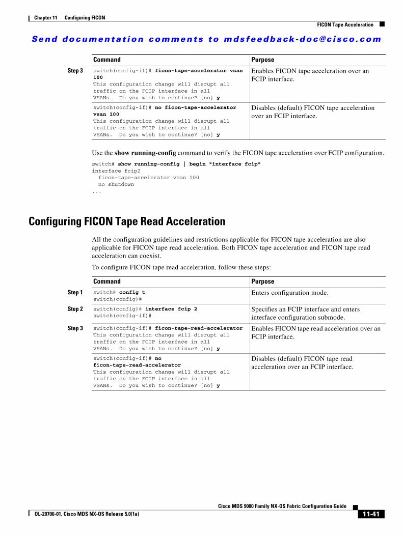
Send documenta t ion comments to mdsfeedback -doc@c i sco .com
Chapter 11 Configuring FICONFICON Tape Acceleration
Use the show running-config command to verify the FICON tape acceleration over FCIP configuration.
switch# show running-config | begin "interface fcip"interface fcip2 ficon-tape-accelerator vsan 100 no shutdown...
Configuring FICON Tape Read AccelerationAll the configuration guidelines and restrictions applicable for FICON tape acceleration are also applicable for FICON tape read acceleration. Both FICON tape acceleration and FICON tape read acceleration can coexist.
To configure FICON tape read acceleration, follow these steps:
Step 3 switch(config-if)# ficon-tape-accelerator vsan 100This configuration change will disrupt all traffic on the FCIP interface in allVSANs. Do you wish to continue? [no] y
Enables FICON tape acceleration over an FCIP interface.
switch(config-if)# no ficon-tape-accelerator vsan 100This configuration change will disrupt all traffic on the FCIP interface in allVSANs. Do you wish to continue? [no] y
Disables (default) FICON tape acceleration over an FCIP interface.
Command Purpose
Command Purpose
Step 1 switch# config tswitch(config)#
Enters configuration mode.
Step 2 switch(config)# interface fcip 2switch(config-if)#
Specifies an FCIP interface and enters interface configuration submode.
Step 3 switch(config-if)# ficon-tape-read-acceleratorThis configuration change will disrupt all traffic on the FCIP interface in allVSANs. Do you wish to continue? [no] y
Enables FICON tape read acceleration over an FCIP interface.
switch(config-if)# no ficon-tape-read-acceleratorThis configuration change will disrupt all traffic on the FCIP interface in allVSANs. Do you wish to continue? [no] y
Disables (default) FICON tape read acceleration over an FCIP interface.
11-41Cisco MDS 9000 Family NX-OS Fabric Configuration Guide
OL-20706-01, Cisco MDS NX-OS Release 5.0(1a)
Send documenta t ion comments to mdsfeedback -doc@c i sco .com
Chapter 11 Configuring FICONConfiguring XRC Acceleration
Configuring XRC AccelerationIBM z/OS Global Mirror eXtended Remote Copy (XRC) is supported on the MSM-18+4 modules. For XRC to function, XRC acceleration must be enabled on the FCIP tunnel interfaces on both ends. XRC acceleration is disabled by default.
To enable XRC acceleration, follow these steps:
Note XRC acceleration and FICON tape acceleration cannot be enabled on the same FCIP tunnel interface and cannot exist in the same VSAN.
Moving a FICON VSAN to an Offline StateIssue the ficon vsan vsan-id offline command in EXEC mode to log out all ports in the VSAN that need to be suspended.
Issue the EXEC-level ficon vsan vsan-id online command in EXEC mode to remove the offline condition and to allow ports to log on again.
Note This command can be issued by the host if the host is allowed to do so (see the “Allowing the Host to Move the Switch Offline” section on page 11-20).
CUP In-Band ManagementThe CUP protocol configures access control and provides unified storage management capabilities from a mainframe computer. Cisco MDS 9000 FICON-enabled switches are fully IBM CUP standard compliant for in-band management using the IBM S/A OS/390 I/O operations console.
Note The CUP specification is proprietary to IBM.
CUP is supported by switches and directors in the Cisco MDS 9000 Family. The CUP function allows the mainframe to manage the Cisco MDS switches.
Host communication includes control functions such as blocking and unblocking ports, as well as monitoring and error reporting functions.
Command Purpose
Step 1 switch# config tswitch(config)#
Enters the configuration mode.
Step 2 switch(config)# interface fcip 2switch(config)#
Specifies an FCIP tunnel interface and enters interface configuration submode.
Step 3 switch(config-if)# ficon-xrc-emulatorswitch(config)#
Enables XRC acceleration over the FCIP interface.
switch(config-if)# no ficon-xrc-emulatorswitch(config)#
Disables (default) XRC acceleration over the FCIP tunnel interface.
11-42Cisco MDS 9000 Family NX-OS Fabric Configuration Guide
OL-20706-01, Cisco MDS NX-OS Release 5.0(1a)

Send documenta t ion comments to mdsfeedback -doc@c i sco .com
Chapter 11 Configuring FICONCUP In-Band Management
This section includes the following topics:
• Placing CUPs in a Zone, page 11-43
• Displaying Control Unit Information, page 11-43
Placing CUPs in a ZoneTo place the CUP in a zone, follow these steps:
Step 1 Set the default zone to permit for the required VSAN.
switch# config tswitch(config)# zone default-zone permit vsan 20
Step 2 Issue the show fcns database command for the required VSAN and obtain the required FICON CUP WWN.
switch# show fcns database vsan 20
VSAN 20:--------------------------------------------------------------------------FCID TYPE PWWN (VENDOR) FC4-TYPE:FEATURE--------------------------------------------------------------------------0x0d0d00 N 50:06:04:88:00:1d:60:83 (EMC) FICON:CU0x0dfe00 N 25:00:00:0c:ce:5c:5e:c2 (Cisco) FICON:CUP0x200400 N 50:05:07:63:00:c2:82:d3 (IBM) scsi-fcp FICON:CU f..0x200800 N 50:05:07:64:01:40:15:0f (IBM) FICON:CH0x20fe00 N 20:00:00:0c:30:ac:9e:82 (Cisco) FICON:CUP
Total number of entries = 5
Note If more than one FICON:CUP WWN exists in this fabric, be sure to add all the FICON:CUP WWN PWWNs to the required zone. The previous sample output displays multiple FICON:CUP occurrences to indicate a cascade configuration.
Step 3 Add the identified FICON:CUP WWN to the zone database.
switch(config)# zone name Zone1 vsan 20switch(config-zone)# member pwwn 25:00:00:0c:ce:5c:5e:c2
Displaying Control Unit InformationExample 11-9 displays configured control device information.
Example 11-9 Displays Control Unit Information
switch# show ficon control-device sb3Control Unit Image:0x80b9c2cVSAN:20 CU:0x20fe00 CUI:0 CUD:0 CURLP:(nil)ASYNC LP:(nil) MODE:1 STATE:1 CQ LEN:0 MAX:0PRIMARY LP: VSAN:0 CH:0x0 CHI:0 CU:0x0 CUI:0ALTERNATE LP: VSAN:0 CH:0x0 CHI:0 CU:0x0 CUI:0
11-43Cisco MDS 9000 Family NX-OS Fabric Configuration Guide
OL-20706-01, Cisco MDS NX-OS Release 5.0(1a)

Send documenta t ion comments to mdsfeedback -doc@c i sco .com
Chapter 11 Configuring FICONDisplaying FICON Information
Logical Path:0x80b9fb4VSAN:20 CH:0x200600 CHI:15 CU:0x20fe00 CUI:0 STATE:1 FLAGS:0x1LINK: OH:0x0 OC:0x0 IH:0x0 IC:0x0DEV: OH:0x0 OC:0x0 IH:0x0 IC:0x0SENSE: 00 00 00 00 00 00 00 46 30 20 00 00 00 00 00 00 00 00 00 00 00 00 00 00 00 00 00 00 00 00 00 00IUI:0x0 DHF:0x0 CCW:0x0 TOKEN:0x0 PCCW:0x0 FCCW:0x0 PTOKEN:0x0 FTOKEN:0x0CMD:0x0 CCW_FLAGS:0x0 CCW_COUNT:0 CMD_FLAGS:0x0 PRIO:0x0 DATA_COUNT:0STATUS:0x0 FLAGS:0x0 PARAM:0x0 QTP:0x0 DTP:0x0CQ LEN:0 MAX:0 DESTATUS:0x0
Displaying FICON InformationThis section includes the following topics:
• Receiving FICON Alerts, page 11-44
• Displaying FICON Port Address Information, page 11-45
• Displaying FICON Configuration File Information, page 11-46
• Displaying the Configured FICON State, page 11-47
• Displaying a Port Administrative State, page 11-48
• Displaying Buffer Information, page 11-48
• Displaying FICON Information in the Running Configuration, page 11-49
• Displaying FICON Information in the Startup Configuration, page 11-50
• Displaying FICON-Related Log Information, page 11-51
Receiving FICON AlertsIn Example 11-10, the user alert mode is Enabled output confirms that you will receive an alert to indicate any changes in the FICON configuration.
Example 11-10 Displays Configured FICON Information
switch# show ficonFicon information for VSAN 20 Ficon is online VSAN is active Host port control is Enabled Host offline control is Enabled User alert mode is Enabled SNMP port control is Enabled Host set director timestamp is Enabled Active=Saved is Disabled Number of implemented ports are 250 Key Counter is 73723 FCID last byte is 0 Date/Time is set by host to Sun Jun 26 00:04:06.991999 1904 Device allegiance is locked by Host Codepage is us-canada Saved configuration files
11-44Cisco MDS 9000 Family NX-OS Fabric Configuration Guide
OL-20706-01, Cisco MDS NX-OS Release 5.0(1a)
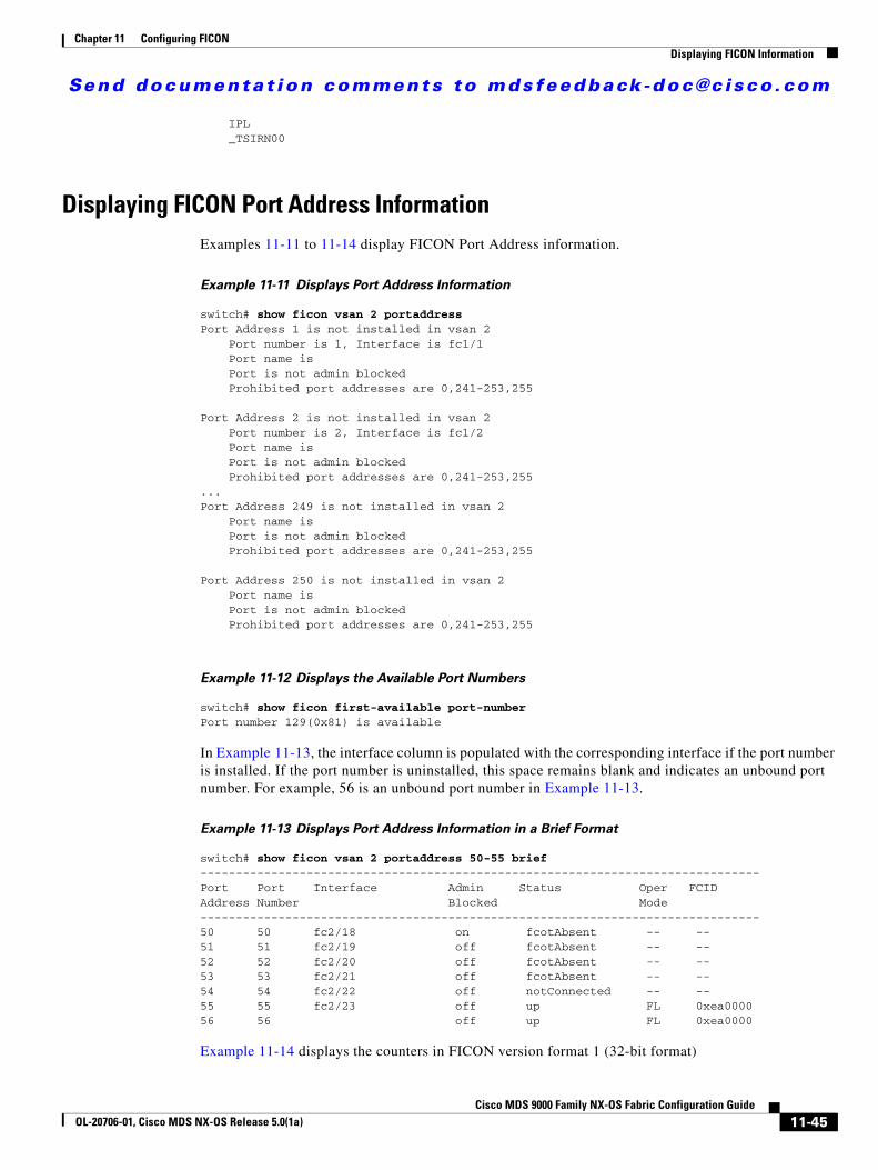
Send documenta t ion comments to mdsfeedback -doc@c i sco .com
Chapter 11 Configuring FICONDisplaying FICON Information
IPL _TSIRN00
Displaying FICON Port Address InformationExamples 11-11 to 11-14 display FICON Port Address information.
Example 11-11 Displays Port Address Information
switch# show ficon vsan 2 portaddressPort Address 1 is not installed in vsan 2 Port number is 1, Interface is fc1/1 Port name is Port is not admin blocked Prohibited port addresses are 0,241-253,255
Port Address 2 is not installed in vsan 2 Port number is 2, Interface is fc1/2 Port name is Port is not admin blocked Prohibited port addresses are 0,241-253,255...Port Address 249 is not installed in vsan 2 Port name is Port is not admin blocked Prohibited port addresses are 0,241-253,255
Port Address 250 is not installed in vsan 2 Port name is Port is not admin blocked Prohibited port addresses are 0,241-253,255
Example 11-12 Displays the Available Port Numbers
switch# show ficon first-available port-numberPort number 129(0x81) is available
In Example 11-13, the interface column is populated with the corresponding interface if the port number is installed. If the port number is uninstalled, this space remains blank and indicates an unbound port number. For example, 56 is an unbound port number in Example 11-13.
Example 11-13 Displays Port Address Information in a Brief Format
switch# show ficon vsan 2 portaddress 50-55 brief-------------------------------------------------------------------------------Port Port Interface Admin Status Oper FCIDAddress Number Blocked Mode-------------------------------------------------------------------------------50 50 fc2/18 on fcotAbsent -- --51 51 fc2/19 off fcotAbsent -- --52 52 fc2/20 off fcotAbsent -- --53 53 fc2/21 off fcotAbsent -- --54 54 fc2/22 off notConnected -- --55 55 fc2/23 off up FL 0xea000056 56 off up FL 0xea0000
Example 11-14 displays the counters in FICON version format 1 (32-bit format)
11-45Cisco MDS 9000 Family NX-OS Fabric Configuration Guide
OL-20706-01, Cisco MDS NX-OS Release 5.0(1a)

Send documenta t ion comments to mdsfeedback -doc@c i sco .com
Chapter 11 Configuring FICONDisplaying FICON Information
Example 11-14 Displays Port Address Counter Information
switch# show ficon vsan 20 portaddress 8 countersPort Address 8(0x8) is up in vsan 20 Port number is 8(0x8), Interface is fc1/8 Version presented 1, Counter size 32b 242811 frames input, 9912794 words 484 class-2 frames, 242302 class-3 frames 0 link control frames, 0 multicast frames 0 disparity errors inside frames 0 disparity errors outside frames 0 frames too big, 0 frames too small 0 crc errors, 0 eof errors 0 invalid ordered sets 0 frames discarded c3 0 address id errors 116620 frames output, 10609188 words 0 frame pacing time 0 link failures 0 loss of sync 0 loss of signal 0 primitive seq prot errors 0 invalid transmission words 1 lrr input, 0 ols input, 5 ols output 0 error summary
Displaying FICON Configuration File InformationExamples 11-15 to 11-17 display FICON configuration file information.
Example 11-15 Displays the Contents of the Specified FICON Configuration File
switch# show ficon vsan 3 file IPLFICON configuration file IPL in vsan 3 Port address 1 Port name is Port is not blocked Prohibited port addresses are 0,81-253,255
Port address 2 Port name is Port is not blocked Prohibited port addresses are 0,81-253,255
Port address 3 Port name is Port is not blocked Prohibited port addresses are 0,81-253,255
Port address 4 Port name is Port is not blocked Prohibited port addresses are 0,81-253,255
...Port address 80 Port name is Port is not blocked Prohibited port addresses are 0,81-253,255
11-46Cisco MDS 9000 Family NX-OS Fabric Configuration Guide
OL-20706-01, Cisco MDS NX-OS Release 5.0(1a)

Send documenta t ion comments to mdsfeedback -doc@c i sco .com
Chapter 11 Configuring FICONDisplaying FICON Information
Port address 254 Port name is Port is not blocked Prohibited port addresses are 0,81-253,255
Example 11-16 Displays All FICON Configuration Files
switch# show ficon vsan 2 Ficon information for VSAN 2 Ficon is enabled VSAN is active Host control is Enabled Host offline control is Enabled Clock alert mode is Disabled User alert mode is Disabled SNMP control is Disabled Active=Saved is Disabled Number of implemented ports are 250 Key Counter is 9 FCID last byte is 0 Date/Time is same as system time(Sun Dec 14 01:26:30.273402 1980) Device Allegiance not locked Codepage is us-canada Saved configuration files IPL IPLFILE1
Example 11-17 Displays the Specified Port Addresses for a FICON Configuration File
switch# show ficon vsan 2 file iplfile1 portaddress 1-7FICON configuration file IPLFILE1 in vsan 2 Port address 1 Port name is Port is not blocked Prohibited port addresses are 0,241-253,255
Port address 2 Port name is Port is not blocked Prohibited port addresses are 0,241-253,255
Port address 3 Port name is P3 Port is not blocked Prohibited port addresses are 0,241-253,255... Port address 7 Port name is Port is not blocked Prohibited port addresses are 0,241-253,255
Displaying the Configured FICON StateIf FICON is enabled on a VSAN, you can display the port address information for that VSAN (see Example 11-18).
11-47Cisco MDS 9000 Family NX-OS Fabric Configuration Guide
OL-20706-01, Cisco MDS NX-OS Release 5.0(1a)

Send documenta t ion comments to mdsfeedback -doc@c i sco .com
Chapter 11 Configuring FICONDisplaying FICON Information
Example 11-18 Displays the Specified Port Address When FICON Is Enabled
switch# show ficon vsan 2 portaddress 55Port Address 55 is not installed in vsan 2 Port number is 55, Interface is fc2/23 Port name is Port is not admin blocked Prohibited port addresses are 0,241-253,255 Admin port mode is FL Port mode is FL, FCID is 0xea0000
Displaying a Port Administrative StateExamples 11-19 to 11-20 display the administrative state of a FICON port. If the port is blocked, the show ficon vsan number portaddress number command displays the blocked state of the port. If a specific port is prohibited, this command also displays the specifically prohibited port (3) along with the ports that are prohibited by default (0, 241 to 253, and 255). If a name is assigned, that name is also displayed.
Example 11-19 Displays an Administratively Unblocked Port
switch# show ficon vsan 2 portaddress 2Port Address 2(0x2) is not installed in vsan 2 Port number is 2(0x2), Interface is fc1/2 Port name is Port is not admin blocked Prohibited port addresses are 0,241-253,255(0,0xf1-0xfd,0xff) Admin port mode is auto Peer is Unknown
Example 11-20 Displays an Administratively Blocked Port
switch# show ficon vsan 2 portaddress 1Port Address 2(0x2) is not installed in vsan 2 Port number is 2(0x2), Interface is fc1/2 Port name is SampleName Port is admin blocked Prohibited port addresses are 0,241-253,255(0,0xf1-0xfd,0xff) Admin port mode is auto Peer is Unknown
Displaying Buffer InformationIn Example 11-21, the Key Counter column displays the 32-bit value maintained by Cisco MDS switches. This value is incremented when any port changes state in that VSAN. The key counter (a 32-bit value) is incremented when a FICON-related configuration is changed. Host programs can increment this value at the start of the channel program and then perform operations on multiple ports. The director history buffer keeps a log of which port address configuration was changed for each key-counter value.
The director history buffer provides a mechanism to determine the change in the port state from the previous time when a value was contained in the key counter.
11-48Cisco MDS 9000 Family NX-OS Fabric Configuration Guide
OL-20706-01, Cisco MDS NX-OS Release 5.0(1a)

Send documenta t ion comments to mdsfeedback -doc@c i sco .com
Chapter 11 Configuring FICONDisplaying FICON Information
Example 11-21 Displays the History Buffer for the Specified VSAN
switch# show ficon vsan 20 director-historyDirector History Buffer for vsan 20---------------------------------------------Key Counter Ports Address Changed---------------------------------------------74556 4374557 4474558 4574559 4674560 4774561 4874562 4974563 5074564 5174565 5274566 5374567 5474568 5574569 5674570 5774571 5874572 5974573 6074574 6174575 6274576 6374577 64745787457974580 1-3,5,10,12,14-16,34-40,43-45,47-54,56-57,59-6474581 3,574582 647458374584 1-3,10,12,14-16,34-40,43-45,47-54,56-57,59-6474585 174586 274587 3
Viewing the History BufferIn the directory history buffer, the Key Counter column displays the 32-bit value maintained by Cisco MDS switches. This value is incremented when any port changes state in that VSAN. The key counter (a 32-bit value) is incremented when a FICON-related configuration is changed. Host programs can increment this value at the start of the channel program and then perform operations on multiple ports. The director history buffer keeps a log of which port address configuration was changed for each key-counter value.
The director history buffer provides a mechanism to determine the change in the port state from the previous time when a value was contained in the key counter.
Displaying FICON Information in the Running ConfigurationExample 11-22 displays the FICON-related information in the running configuration.
11-49Cisco MDS 9000 Family NX-OS Fabric Configuration Guide
OL-20706-01, Cisco MDS NX-OS Release 5.0(1a)
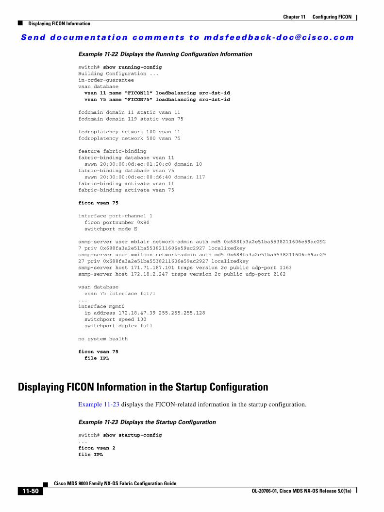
Send documenta t ion comments to mdsfeedback -doc@c i sco .com
Chapter 11 Configuring FICONDisplaying FICON Information
Example 11-22 Displays the Running Configuration Information
switch# show running-config Building Configuration ...in-order-guaranteevsan database vsan 11 name “FICON11” loadbalancing src-dst-id vsan 75 name “FICON75” loadbalancing src-dst-id
fcdomain domain 11 static vsan 11fcdomain domain 119 static vsan 75
fcdroplatency network 100 vsan 11fcdroplatency network 500 vsan 75
feature fabric-bindingfabric-binding database vsan 11 swwn 20:00:00:0d:ec:01:20:c0 domain 10fabric-binding database vsan 75 swwn 20:00:00:0d:ec:00:d6:40 domain 117fabric-binding activate vsan 11fabric-binding activate vsan 75
ficon vsan 75
interface port-channel 1 ficon portnumber 0x80 switchport mode E
snmp-server user mblair network-admin auth md5 0x688fa3a2e51ba5538211606e59ac2927 priv 0x688fa3a2e51ba5538211606e59ac2927 localizedkeysnmp-server user wwilson network-admin auth md5 0x688fa3a2e51ba5538211606e59ac2927 priv 0x688fa3a2e51ba5538211606e59ac2927 localizedkeysnmp-server host 171.71.187.101 traps version 2c public udp-port 1163snmp-server host 172.18.2.247 traps version 2c public udp-port 2162
vsan database vsan 75 interface fc1/1...interface mgmt0 ip address 172.18.47.39 255.255.255.128 switchport speed 100 switchport duplex full
no system health
ficon vsan 75 file IPL
Displaying FICON Information in the Startup ConfigurationExample 11-23 displays the FICON-related information in the startup configuration.
Example 11-23 Displays the Startup Configuration
switch# show startup-config ...ficon vsan 2file IPL
11-50Cisco MDS 9000 Family NX-OS Fabric Configuration Guide
OL-20706-01, Cisco MDS NX-OS Release 5.0(1a)
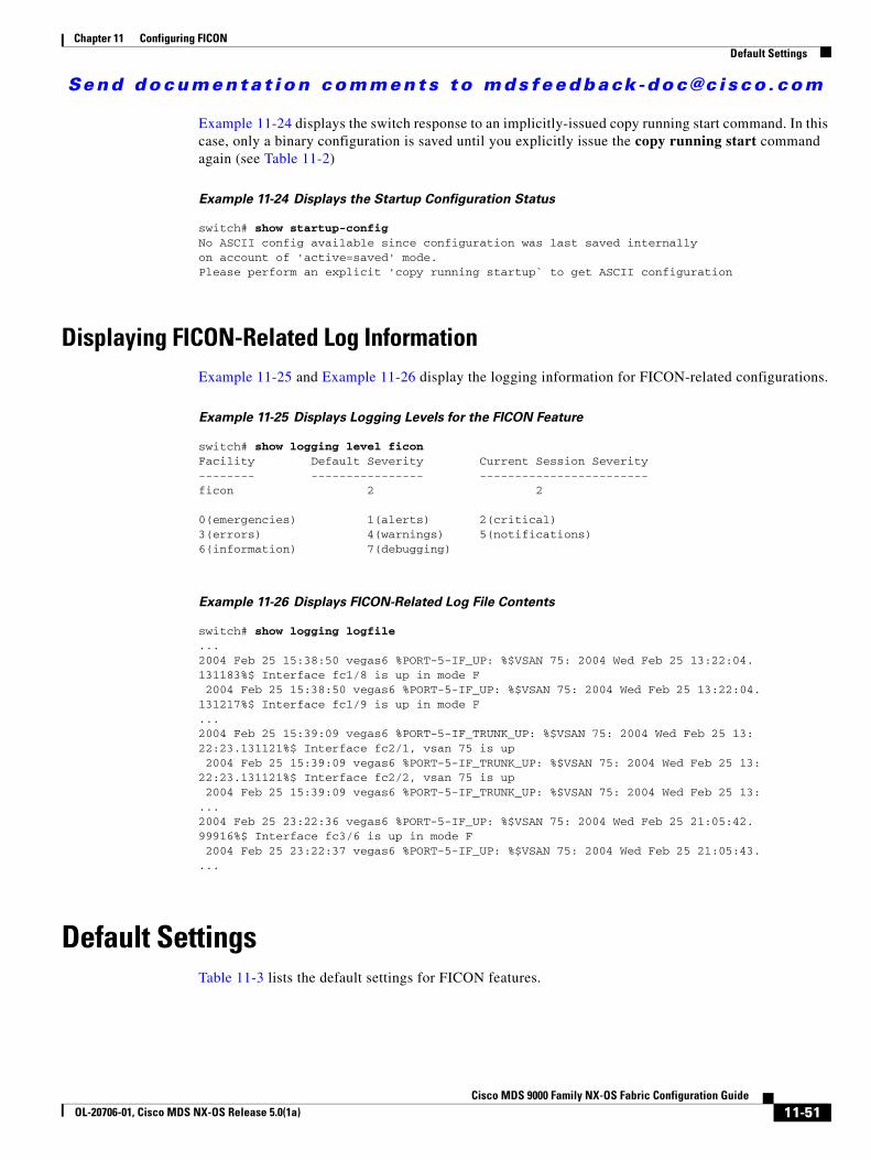
Send documenta t ion comments to mdsfeedback -doc@c i sco .com
Chapter 11 Configuring FICONDefault Settings
Example 11-24 displays the switch response to an implicitly-issued copy running start command. In this case, only a binary configuration is saved until you explicitly issue the copy running start command again (see Table 11-2)
Example 11-24 Displays the Startup Configuration Status
switch# show startup-configNo ASCII config available since configuration was last saved internallyon account of 'active=saved' mode.Please perform an explicit 'copy running startup` to get ASCII configuration
Displaying FICON-Related Log InformationExample 11-25 and Example 11-26 display the logging information for FICON-related configurations.
Example 11-25 Displays Logging Levels for the FICON Feature
switch# show logging level ficonFacility Default Severity Current Session Severity-------- ---------------- ------------------------ficon 2 2
0(emergencies) 1(alerts) 2(critical)3(errors) 4(warnings) 5(notifications)6(information) 7(debugging)
Example 11-26 Displays FICON-Related Log File Contents
switch# show logging logfile...2004 Feb 25 15:38:50 vegas6 %PORT-5-IF_UP: %$VSAN 75: 2004 Wed Feb 25 13:22:04.131183%$ Interface fc1/8 is up in mode F 2004 Feb 25 15:38:50 vegas6 %PORT-5-IF_UP: %$VSAN 75: 2004 Wed Feb 25 13:22:04.131217%$ Interface fc1/9 is up in mode F...2004 Feb 25 15:39:09 vegas6 %PORT-5-IF_TRUNK_UP: %$VSAN 75: 2004 Wed Feb 25 13:22:23.131121%$ Interface fc2/1, vsan 75 is up 2004 Feb 25 15:39:09 vegas6 %PORT-5-IF_TRUNK_UP: %$VSAN 75: 2004 Wed Feb 25 13:22:23.131121%$ Interface fc2/2, vsan 75 is up 2004 Feb 25 15:39:09 vegas6 %PORT-5-IF_TRUNK_UP: %$VSAN 75: 2004 Wed Feb 25 13:...2004 Feb 25 23:22:36 vegas6 %PORT-5-IF_UP: %$VSAN 75: 2004 Wed Feb 25 21:05:42.99916%$ Interface fc3/6 is up in mode F 2004 Feb 25 23:22:37 vegas6 %PORT-5-IF_UP: %$VSAN 75: 2004 Wed Feb 25 21:05:43....
Default SettingsTable 11-3 lists the default settings for FICON features.
11-51Cisco MDS 9000 Family NX-OS Fabric Configuration Guide
OL-20706-01, Cisco MDS NX-OS Release 5.0(1a)

Send documenta t ion comments to mdsfeedback -doc@c i sco .com
Chapter 11 Configuring FICONDefault Settings
Table 11-3 Default FICON Settings
Parameters Default
FICON feature Disabled.
Port numbers Same as port addresses.
FC ID last byte value 0 (zero).
EBCDIC format option US-Canada.
Switch offline state Hosts are allowed to move the switch to an offline state.
Mainframe users Allowed to configure FICON parameters on Cisco MDS switches.
Clock in each VSAN Same as the switch hardware clock.
Host clock control Allows host to set the clock on this switch.
SNMP users Configure FICON parameters.
Port address Not blocked
Prohibited ports Ports90–253 and 255 for the Cisco MDS 9200 Series switches.
Ports250–253 and 255 for the Cisco MDS 9500 Series switches.
11-52Cisco MDS 9000 Family NX-OS Fabric Configuration Guide
OL-20706-01, Cisco MDS NX-OS Release 5.0(1a)

Send documenta t ion comments to mdsfeedback -doc@c i sco .com
Cisco MOL-20706-01, Cisco MDS NX-OS Release 5.0(1a)
C H A P T E R 12
Advanced Features and ConceptsThis chapter describes the advanced features provided in switches in the Cisco MDS 9000 Family. It includes the following sections:
• Common Information Model, page 12-1
• Fibre Channel Time-Out Values, page 12-5
• World Wide Names, page 12-9
• FC ID Allocation for HBAs, page 12-11
• Switch Interoperability, page 12-13
• Default Settings, page 12-20
Common Information ModelCommon Information Model (CIM) is an object-oriented information model that extends the existing standards for describing management information in a network/enterprise environment.
CIM messages are independent of platform and implementation because they are encoded in N Extensible Markup Language (XML). CIM consists of a specification and a schema. The specification defines the syntax and rules for describing management data and integrating with other management models. The schema provides the actual model descriptions for systems, applications, networks, and devices.
For more information about CIM, refer to the specification available through the Distributed Management Task Force (DMTF) website at the following URL: http://www.dmtf.org/
For further information about Cisco MDS 9000 Family support for CIM servers, refer to the Cisco MDS 9000 Family CIM Programming Reference Guide.
A CIM client is required to access the CIM server. The client can be any client that supports CIM.
This section contains the following sections:
• SSL Certificate Requirements and Format, page 12-2
• Configuring the CIM Server, page 12-2
• Displaying CIM Information, page 12-3
12-1DS 9000 Family NX-OS Fabric Configuration Guide

Send documenta t ion comments to mdsfeedback -doc@c i sco .com
Chapter 12 Advanced Features and ConceptsCommon Information Model
SSL Certificate Requirements and FormatTo limit access to the CIM server to authorized clients, you can enable the HTTPS transport protocol between the CIM server and client. On the switch side, you must install a Secure Socket Library (SSL) certificate generated on the client and enable the HTTPS server. Certificates may be generated using third-party tools, such as openssl (available for UNIX, Mac and Windows), and may be certified by a CA or self-signed.
The SSL certificate that you install on the switch must meet the following requirements:
• The certificate file contains the certificate and the private key.
• The private key must be RSA type.
• The certificate file should be in Private Electronic Mail (PEM) style format and have .pem as the extension.
-----BEGIN CERTIFICATE-----(certificate goes here)-----END CERTIFICATE----------BEGIN RSA PRIVATE KEY-----(private key goes here)-----END RSA PRIVATE KEY-----
Only one certificate file can be installed at a time.
Configuring the CIM ServerTo configure the CIM server on the switch, follow these steps:
Step 1 (Optional) Install an SSL certificate.
Step 2 (Optional) Configure the transport protocol.
Step 3 Enable the CIM server.
This section includes the following topics:
• Installing an SSL Certificate for the CIM Server, page 12-2
• Configuring the Transport Protocol for the CIM Server, page 12-3
• Enabling the CIM Server, page 12-3
Installing an SSL Certificate for the CIM Server
To install a conforming SSL certificate for the CIM server, follow these steps:
Command Purpose
Step 1 switch# config t Enters configuration mode.
Step 2 switch(config)# switch(config)# cimserver certificate bootflash:simserver.pem
Installs an SSL certificate specified in the file named with a .pem extension
switch(config)# cimserver clearcertificate (Optional) Uninstalls the currently installed SSL certificate.
12-2Cisco MDS 9000 Family NX-OS Fabric Configuration Guide
OL-20706-01, Cisco MDS NX-OS Release 5.0(1a)

Send documenta t ion comments to mdsfeedback -doc@c i sco .com
Chapter 12 Advanced Features and ConceptsCommon Information Model
Configuring the Transport Protocol for the CIM Server
The default transport protocol for the CIM server is HTTP. This protocol uses the wbem-http port (TCP port 5988). HTTPS for CIM uses the wbem-https port (TCP port 5989).
To configure the CIM server to use only the HTTPS protocol, follow these steps:
Enabling the CIM Server
The CIM server is disabled in all switches in the Cisco MDS 9000 Family by default. To use the CIM server, you must explicitly enable it on the required switches in the fabric.
To enable the CIM server, follow these steps:
Displaying CIM InformationTo display CIM information, use the show cimserver command (see Example 12-1 through Example 12-11).
Example 12-1 Displays CIM Server Status
switch# show cimserver statuscimserver is enabled
Example 12-2 Displays the CIM Server HTTPS Status
switch# show cimserver httpsstatus cimserver Https is enabled
Example 12-3 Displays the CIM Server HTTP Status
switch# show cimserver httpstatus cimserver Http is not enabled
Example 12-4 Displays CIM Server Indication
switch# show cimserver indicationFilter: root/cimv2:Feb 7, 2008 2:32:11 PMQuery: "SELECT * FROM CISCO_LinkUp"Query Language: WQL
Command Purpose
Step 1 switch# config t Enters configuration mode.
Step 2 switch(config)# cimserver enableHttps Enables the HTTPS protocol for CIM.
switch(config)# no cimserver enableHttp Disables the HTTP protocol for CIM.
Command Purpose
Step 1 switch# config t Enters configuration mode.
Step 2 switch(config)# feature cimserver Enables the CIM server.
switch(config)# no feature cimserver Disables the CIM server (default).
12-3Cisco MDS 9000 Family NX-OS Fabric Configuration Guide
OL-20706-01, Cisco MDS NX-OS Release 5.0(1a)

Send documenta t ion comments to mdsfeedback -doc@c i sco .com
Chapter 12 Advanced Features and ConceptsCommon Information Model
-----------------------------------------Handler: root/cimv2:CIM_ListenerDestinationCIMXML.Thu Feb 07 14:32:44 IST 20081202374964083Destination: http://10.77.91.110:59901PersistenceType: Transient-----------------------------------------Namespace: root/cimv2Filter: root/cimv2:Feb 7, 2008 2:32:11 PMHandler: root/cimv2:CIM_ListenerDestinationCIMXML.Thu Feb 07 14:32:44 IST 20081202374964083Query: "SELECT * FROM CISCO_LinkUp"Destination: http://10.77.91.110:59901SubscriptionState: Enabled-----------------------------------------
Example 12-5 Displays CIM Server Indication Filters
switch# show cimserver indication filtersFilter: root/cimv2:Feb 7, 2008 2:32:11 PMQuery: "SELECT * FROM CISCO_LinkUp"Query Language: WQL
Example 12-6 Displays CIM Server Indication Recipients
switch# show cimserver indication recipients Handler: root/cimv2:CIM_ListenerDestinationCIMXML.Thu Feb 07 14:32:44 IST 20081202374964083Destination: http://10.77.91.110:59901PersistenceType: Transient
Example 12-7 Displays CIM Server Indication Subscriptions
switch# show cimserver indication subscriptionsNamespace: root/cimv2Filter: root/cimv2:Feb 7, 2008 2:32:11 PMHandler: root/cimv2:CIM_ListenerDestinationCIMXML.Thu Feb 07 14:32:44 IST 20081202374964083Query: "SELECT * FROM CISCO_LinkUp"Destination: http://10.77.91.110:59901SubscriptionState: Enabledcimserver certificate file name is servcert.pem
Example 12-8 Displays the CIM Server Configuration
switch# show cimserver cimserver is enabled cimserver Http is not enabled cimserver Https is enabled cimserver certificate file name is servcert.pem Current value for the property logLevel in CIMServer is 'WARNING'.
Example 12-9 Displays CIM Server Logs
switch# show cimserver logshttpsstatus02/07/2008-16:38:14 INFO cimserver: Sent response to: localhost02/07/2008-16:38:26 INFO cimserver: Received request from: 10.77.91.110
12-4Cisco MDS 9000 Family NX-OS Fabric Configuration Guide
OL-20706-01, Cisco MDS NX-OS Release 5.0(1a)

Send documenta t ion comments to mdsfeedback -doc@c i sco .com
Chapter 12 Advanced Features and ConceptsFibre Channel Time-Out Values
02/07/2008-16:38:27 INFO cimserver: Sent response to: 10.77.91.110
Example 12-10 Configuring CIM Server Loglevel
switch# conf tEnter configuration commands, one per line. End with CNTL/Z.switch(config)# cimserver logLevel ? <1-5> 1-trace;2-information;3-warning;4-severe;5-fatalswitch(config)# cimserver logLevel 2Current value for the property logLevel is set to "INFORMATION" in CIMServer. cimserver Https is enabled
Example 12-11 Displays CIM Server Certificate Files
switch# show cimserver certificateNamecimserver certificate file name is servcert.pem
Fibre Channel Time-Out ValuesYou can modify Fibre Channel protocol related timer values for the switch by configuring the following time-out values (TOVs):
• Distributed services TOV (D_S_TOV)—The valid range is from 5,000 to 10,000 milliseconds. The default is 5,000 milliseconds.
• Error detect TOV (E_D_TOV)—The valid range is from 1,000 to 10,000 milliseconds. The default is 2,000 milliseconds. This value is matched with the other end during port initialization.
• Resource allocation TOV (R_A_TOV)—The valid range is from 5,000 to 10,000 milliseconds. The default is 10,000 milliseconds. This value is matched with the other end during port initialization.
Note The fabric stability TOV (F_S_TOV) constant cannot be configured.
This section includes the following topics:
• Timer Configuration Across All VSANs, page 12-6
• Timer Configuration Per-VSAN, page 12-6
• About fctimer Distribution, page 12-7
• Enabling fctimer Distribution, page 12-7
• Committing fctimer Changes, page 12-7
• Discarding fctimer Changes, page 12-8
• Fabric Lock Override, page 12-8
• Database Merge Guidelines, page 12-8
• Displaying Configured fctimer Values, page 12-9
12-5Cisco MDS 9000 Family NX-OS Fabric Configuration Guide
OL-20706-01, Cisco MDS NX-OS Release 5.0(1a)

Send documenta t ion comments to mdsfeedback -doc@c i sco .com
Chapter 12 Advanced Features and ConceptsFibre Channel Time-Out Values
Timer Configuration Across All VSANsYou can modify Fibre Channel protocol related timer values for the switch.
Caution The D_S_TOV, E_D_TOV, and R_A_ TOV values cannot be globally changed unless all VSANs in the switch are suspended.
Note If a VSAN is not specified when you change the timer value, the changed value is applied to all VSANs in the switch.
To configure Fibre Channel timers across all VSANs, follow these steps:
Timer Configuration Per-VSANYou can also issue the fctimer for a specified VSAN to configure different TOV values for VSANs with special links like FC or IP tunnels. You can configure different E_D_TOV, R_A_TOV, and D_S_TOV values for individual VSANs. Active VSANs are suspended and activated when their timer values are changed.
Caution You cannot perform a nondisruptive downgrade to any earlier version that does not support per-VSAN FC timers.
Note This configuration must be propagated to all switches in the fabric—be sure to configure the same value in all switches in the fabric.
If a switch is downgraded to Cisco MDS SAN-OS Release 1.2 or 1.1 after the timer is configured for a VSAN, an error message is issued to warn against strict incompatibilities. Refer to the Cisco MDS 9000 Family Troubleshooting Guide.
Command Purpose
Step 1 switch# config tswitch(config)
Enters configuration mode.
Step 2 switch(config)# fctimer R_A_TOV 6000 Configures the R_A_TOV value for all VSANs to be 6000 msec. This type of configuration is not permitted unless all VSANs are suspended.
12-6Cisco MDS 9000 Family NX-OS Fabric Configuration Guide
OL-20706-01, Cisco MDS NX-OS Release 5.0(1a)

Send documenta t ion comments to mdsfeedback -doc@c i sco .com
Chapter 12 Advanced Features and ConceptsFibre Channel Time-Out Values
To configure per-VSAN Fiber Channel timers, follow these steps:
About fctimer DistributionYou can enable per-VSAN fctimer fabric distribution for all Cisco MDS switches in the fabric. When you perform fctimer configurations, and distribution is enabled, that configuration is distributed to all the switches in the fabric.
You automatically acquire a fabric-wide lock when you issue the first configuration command after you enabled distribution in a switch. The fctimer application uses the effective and pending database model to store or commit the commands based on your configuration.
Refer to the Cisco MDS 9000 Family NX-OS System Management Configuration Guide for more information on the CFS application.
Enabling fctimer DistributionTo enable or disable fctimer fabric distribution, follow these steps:
Committing fctimer ChangesWhen you commit the fctimer configuration changes, the effective database is overwritten by the configuration changes in the pending database and all the switches in the fabric receive the same configuration. When you commit the fctimer configuration changes without implementing the session feature, the fctimer configurations are distributed to all the switches in the physical fabric.
Command Purpose
Step 1 switch# config tswitch(config)
Enters configuration mode.
Step 2 switch(config#)# fctimer D_S_TOV 6000 vsan 2 Warning: The vsan will be temporarily suspended when updating the timer value This configuration would impact whole fabric. Do you want to continue? (y/n) ySince this configuration is not propagated to other switches, please configure the same value in all the switches
Configures the D_S_TOV value to be 6000 msec for VSAN 2. Suspends the VSAN temporarily. You have the option to end this command, if required.
Command Purpose
Step 1 switch# config t Enters configuration mode.
Step 2 switch(config)# fctimer distribute Enables fctimer configuration distribution to all switches in the fabric. Acquires a fabric lock and stores all future configuration changes in the pending database.
switch(config)# no fctimer distribute Disables (default) fctimer configuration distribution to all switches in the fabric.
12-7Cisco MDS 9000 Family NX-OS Fabric Configuration Guide
OL-20706-01, Cisco MDS NX-OS Release 5.0(1a)

Send documenta t ion comments to mdsfeedback -doc@c i sco .com
Chapter 12 Advanced Features and ConceptsFibre Channel Time-Out Values
To commit the fctimer configuration changes, follow these steps:
Discarding fctimer ChangesAfter making the configuration changes, you can choose to discard the changes by discarding the changes instead of committing them. In either case, the lock is released.
To discard the fctimer configuration changes, follow these steps:
Fabric Lock OverrideIf you have performed a fctimer fabric task and have forgotten to release the lock by either committing or discarding the changes, an administrator can release the lock from any switch in the fabric. If the administrator performs this task, your changes to the pending database are discarded and the fabric lock is released.
Tip The changes are only available in the volatile directory and are subject to being discarded if the switch is restarted.
To use administrative privileges and release a locked fctimer session, use the clear fctimer session command.
switch# clear fctimer session
Database Merge GuidelinesFor information about CFS merge support, refer to the Cisco MDS 9000 Family NX-OS System Management Configuration Guide.
When merging two fabrics, follow these guidelines:
• Be aware of the following merge conditions:
– The merge protocol is not implemented for distribution of the fctimer values—you must manually merge the fctimer values when a fabric is merged.The per-VSAN fctimer configuration is distributed in the physical fabric.
Command Purpose
Step 1 switch# config t Enters configuration mode.
Step 2 switch(config)# fctimer commit Distributes the fctimer configuration changes to all switches in the fabric and releases the lock. Overwrites the effective database with the changes made to the pending database.
Command Purpose
Step 1 switch# config t Enters configuration mode.
Step 2 switch(config)# fctimer abort Discards the fctimer configuration changes in the pending database and releases the fabric lock.
12-8Cisco MDS 9000 Family NX-OS Fabric Configuration Guide
OL-20706-01, Cisco MDS NX-OS Release 5.0(1a)

Send documenta t ion comments to mdsfeedback -doc@c i sco .com
Chapter 12 Advanced Features and ConceptsWorld Wide Names
– The fctimer configuration is only applied to those switches containing the VSAN with a modified fctimer value.
– The global fctimer values are not distributed.
• Do not configure global timer values when distribution is enabled.
Note The number of pending fctimer configuration operations cannot be more than 15. At that point, you must commit or abort the pending configurations before performing any more operations.
Displaying Configured fctimer ValuesUse the show fctimer command to display the configured fctimer values (see Examples 12-12 and 12-13).
Example 12-12 Displays Configured Global TOVs
switch# show fctimerF_S_TOV D_S_TOV E_D_TOV R_A_TOV----------------------------------------5000 ms 5000 ms 2000 ms 10000 ms
Note The F_S_TOV constant, though not configured, is displayed in the output of the show fctimer command.
Example 12-13 Displays Configured TOVs for a Specified VSAN
switch# show fctimer vsan 10vsan no. F_S_TOV D_S_TOV E_D_TOV R_A_TOV -------------------------------------------------10 5000 ms 5000 ms 3000 ms 10000 ms
World Wide NamesThe world wide name (WWN) in the switch is equivalent to the Ethernet MAC address. As with the MAC address, you must uniquely associate the WWN to a single device. The principal switch selection and the allocation of domain IDs rely on the WWN. The WWN manager, a process-level manager residing on the switch’s supervisor module, assigns WWNs to each switch.
Cisco MDS 9000 Family switches support three network address authority (NAA) address formats (see Table 12-1).
Table 12-1 Standardized NAA WWN Formats
NAA Address NAA Type WWN Format
IEEE 48-bit address Type 1 = 0001b 000 0000 0000b 48-bit MAC address
IEEE extended Type 2 = 0010b Locally assigned 48-bit MAC address
IEEE registered Type 5 = 0101b IEEE company ID: 24 bits VSID: 36 bits
12-9Cisco MDS 9000 Family NX-OS Fabric Configuration Guide
OL-20706-01, Cisco MDS NX-OS Release 5.0(1a)

Send documenta t ion comments to mdsfeedback -doc@c i sco .com
Chapter 12 Advanced Features and ConceptsWorld Wide Names
Caution Changes to the world-wide names should be made by an administrator or individual who is completely familiar with switch operations.
This section includes the following topics:
• Displaying WWN Information, page 12-10
• Link Initialization WWN Usage, page 12-10
• Configuring a Secondary MAC Address, page 12-11
Displaying WWN InformationUse the show wwn commands to display the status of the WWN configuration. See Examples 12-14 to 12-16.
Example 12-14 Displays the Status of All WWNs
switch# show wwn status Type 1 WWNs: Configured: 64 Available: 48 (75%) Resvd.: 16 Types 2 & 5 WWNs: Configured: 524288 Available: 450560 (85%) Resvd.: 73728NKAU & NKCR WWN Blks: Configured: 1760 Available: 1760 (100%) Alarm Status: Type1: NONE Types 2&5: NONE
Example 12-15 Displays Specified Block ID Information
switch# show wwn status block-id 51 WWNs in this block: 21:00:ac:16:5e:52:00:03 to 21:ff:ac:16:5e:52:00:03Num. of WWNs:: Configured: 256 Allocated: 0 Available: 256 Block Allocation Status: FREE
Example 12-16 Displays the WWN for a Specific Switch
switch# show wwn switch Switch WWN is 20:00:ac:16:5e:52:00:00
Link Initialization WWN Usage Exchange Link Protocol (ELP) and Exchange Fabric Protocol (EFP) use WWNs during link initialization. The usage details differ based on the Cisco NX-OS software release.
Both ELPs and EFPs use the VSAN WWN by default during link initialization. However, the ELP usage changes based on the peer switch’s usage:
• If the peer switch ELP uses the switch WWN, then the local switch also uses the switch WWN.
• If the peer switch ELP uses the VSAN WWN, then the local switch also uses the VSAN WWN.
Note As of Cisco SAN-OS Release 2.0(2b), the ELP is enhanced to be compliant with FC-SW-3.
12-10Cisco MDS 9000 Family NX-OS Fabric Configuration Guide
OL-20706-01, Cisco MDS NX-OS Release 5.0(1a)

Send documenta t ion comments to mdsfeedback -doc@c i sco .com
Chapter 12 Advanced Features and ConceptsFC ID Allocation for HBAs
Configuring a Secondary MAC AddressTo allocate secondary MAC addresses, follow these steps:
FC ID Allocation for HBAsFibre Channel standards require a unique FC ID to be allocated to an N port attached to a Fx port in any switch. To conserve the number of FC IDs used, Cisco MDS 9000 Family switches use a special allocation scheme.
Some HBAs do not discover targets that have FC IDs with the same domain and area. Prior to Cisco SAN-OS Release 2.0(1b), the Cisco SAN-OS software maintained a list of tested company IDs that do not exhibit this behavior. These HBAs were allocated with single FC IDs, and for others a full area was allocated.
The FC ID allocation scheme available in Release 1.3 and earlier, allocates a full area to these HBAs. This allocation isolates them to that area and are listed with their pWWN during a fabric login. The allocated FC IDs are cached persistently and are still available in Cisco SAN-OS Release 2.0(1b) (see the “FC ID Allocation for HBAs” section on page 12-11).
To allow further scalability for switches with numerous ports, the Cisco NX-OS software maintains a list of HBAs exhibiting this behavior. Each HBA is identified by its company ID (also known known as Organizational Unique Identifier, or OUI) used in the pWWN during a fabric login. A full area is allocated to the N ports with company IDs that are listed, and for the others a single FC ID is allocated. Regardless of the kind (whole area or single) of FC ID allocated, the FC ID entries remain persistent.
This section includes the following topics:
• Default Company ID List, page 12-11
• Verifying the Company ID Configuration, page 12-12
Default Company ID ListAll switches in the Cisco MDS 9000 Family that ship with Cisco SAN-OS Release 2.0(1b) or later, or NX-OS 4.1(1) contain a default list of company IDs that require area allocation. Using the company ID reduces the number of configured persistent FC ID entries. You can configure or modify these entries using the CLI.
Command Purpose
Step 1 switch# config tswitch(config)#
Enters configuration mode.
Step 2 switch(config)# wwn secondary-mac 00:99:55:77:55:55 range 64 This command CANNOT be undone. Please enter the BASE MAC ADDRESS again: 00:99:55:77:55:55Please enter the mac address RANGE again: 64From now on WWN allocation would be based on new MACs.Are you sure? (yes/no) noYou entered: no. Secondary MAC NOT programmed
Configures the secondary MAC address. This command cannot be undone.
12-11Cisco MDS 9000 Family NX-OS Fabric Configuration Guide
OL-20706-01, Cisco MDS NX-OS Release 5.0(1a)

Send documenta t ion comments to mdsfeedback -doc@c i sco .com
Chapter 12 Advanced Features and ConceptsFC ID Allocation for HBAs
Caution Persistent entries take precedence over company ID configuration. If the HBA fails to discover a target, verify that the HBA and the target are connected to the same switch and have the same area in their FC IDs, then perform the following procedure: 1. Shut down the port connected to the HBA. 2. Clear the persistent FC ID entry. 3. Get the company ID from the Port WWN. 4. Add the company ID to the list that requires area allocation. 5. Bring up the port.
The list of company IDs have the following characteristics:
• A persistent FC ID configuration always takes precedence over the list of company IDs. Even if the company ID is configured to receive an area, the persistent FC ID configuration results in the allocation of a single FC ID.
• New company IDs added to subsequent releases are automatically added to existing company IDs.
• The list of company IDs is saved as part of the running and saved configuration.
• The list of company IDs is used only when the fcinterop FC ID allocation scheme is in auto mode. By default, the interop FC ID allocation is set to auto, unless changed.
Tip We recommend that you set the fcinterop FC ID allocation scheme to auto and use the company ID list and persistent FC ID configuration to manipulate the FC ID device allocation.
Use the fcinterop FCID allocation auto command to change the FC ID allocation and the show running-config command to view the currently allocated mode.
• When you issue a write erase, the list inherits the default list of company IDs shipped with a relevant release.
To allocate company IDs, follow these steps:
Verifying the Company ID ConfigurationYou can view the configured company IDs by issuing the show fcid-allocation area command (see Example 12-17). Default entries are listed first and the user-added entries are listed next. Entries are listed even if they were part of the default list and you later removed them.
Example 12-17 Displays the List of Default and Configured Company IDs
switch# show fcid-allocation area
Command Purpose
Step 1 switch# config tswitch(config)#
Enters configuration mode.
Step 2 switch(config)# fcid-allocation area company-id 0x003223
Adds a new company ID to the default list.
switch(config)# no fcid-allocation area company-id 0x00E069
Deletes a company ID from the default list.
switch(config)# fcid-allocation area company-id 0x003223
Adds a new company ID to the default list.
12-12Cisco MDS 9000 Family NX-OS Fabric Configuration Guide
OL-20706-01, Cisco MDS NX-OS Release 5.0(1a)

Send documenta t ion comments to mdsfeedback -doc@c i sco .com
Chapter 12 Advanced Features and ConceptsSwitch Interoperability
FCID area allocation company id info:00:50:2E <-------------------- Default entry00:50:8B00:60:B000:A0:B800:E0:6900:30:AE + <------------------ User-added entry00:32:23 +
00:E0:8B * <------------- Explicitly deleted entry (from the original default list)Total company ids: 7+ - Additional user configured company ids.* - Explicitly deleted company ids from default list.
You can implicitly derive the default entries shipped with a specific release by combining the list of Company IDs displayed without any identification with the list of deleted entries.
You can also view or obtain the company IDs in a specific WWN by issuing the show fcid-allocation company-id-from-wwn command (see Example 12-18). Some WWN formats do not support company IDs. In these cases, you many need to configure the FC ID persistent entry.
Example 12-18 Displays the Company ID for the Specified WWN
switch# show fcid-allocation company-id-from-wwn 20:00:00:05:30:00:21:60Extracted Company ID: 0x000530
Switch InteroperabilityInteroperability enables the products of multiple vendors to interact with each other. Fibre Channel standards guide vendors towards common external Fibre Channel interfaces.
If all vendors followed the standards in the same manner, then interconnecting different products would become a trivial exercise. However, not all vendors follow the standards in the same way, thus resulting in interoperability modes. This section briefly explains the basic concepts of these modes.
Each vendor has a regular mode and an equivalent interoperability mode, which specifically turns off advanced or proprietary features and provides the product with a more amiable standards-compliant implementation.
Note For more information on configuring interoperability for the Cisco MDS 9000 Family switches, refer to the Cisco MDS 9000 Family Switch-to-Switch Interoperability Configuration Guide.
This section includes the following topics:
• About Interop Mode, page 12-13
• Configuring Interop Mode 1, page 12-16
About Interop ModeCisco NX-OS software supports the following four interop modes:
• Mode 1— Standards based interop mode that requires all other vendors in the fabric to be in interop mode.
12-13Cisco MDS 9000 Family NX-OS Fabric Configuration Guide
OL-20706-01, Cisco MDS NX-OS Release 5.0(1a)

Send documenta t ion comments to mdsfeedback -doc@c i sco .com
Chapter 12 Advanced Features and ConceptsSwitch Interoperability
• Mode 2—Brocade native mode (Core PID 0).
• Mode 3—Brocade native mode (Core PID 1).
• Mode 4—McData native mode.
For information about configuring interop modes 2, 3, and 4, refer to the Cisco MDS 9000 Family Switch-to-Switch Interoperability Configuration Guide.
Table 12-2 lists the changes in switch behavior when you enable interoperability mode. These changes are specific to switches in the Cisco MDS 9000 Family while in interop mode.
Table 12-2 Changes in Switch Behavior When Interoperability Is Enabled
Switch Feature Changes if Interoperability Is Enabled
Domain IDs Some vendors cannot use the full range of 239 domains within a fabric.
Domain IDs are restricted to the range 97-127. This is to accommodate McData’s nominal restriction to this same range. They can either be set up statically (the Cisco MDS switch accept only one domain ID, if it does not get that domain ID it isolates itself from the fabric) or preferred. (If it does not get its requested domain ID, it accepts any assigned domain ID.)
Timers All Fibre Channel timers must be the same on all switches as these values are exchanged by E ports when establishing an ISL. The timers are F_S_TOV, D_S_TOV, E_D_TOV, and R_A_TOV.
F_S_TOV Verify that the Fabric Stability Time Out Value timers match exactly.
D_S_TOV Verify that the Distributed Services Time Out Value timers match exactly.
E_D_TOV Verify that the Error Detect Time Out Value timers match exactly.
R_A_TOV Verify that the Resource Allocation Time Out Value timers match exactly.
Trunking Trunking is not supported between two different vendor’s switches. This feature may be disabled on a per port or per switch basis.
Default zone The default zone behavior of permit (all nodes can see all other nodes) or deny (all nodes are isolated when not explicitly placed in a zone) may change.
Zoning attributes Zones may be limited to the pWWN and other proprietary zoning methods (physical port number) may be eliminated.
Note Brocade uses the cfgsave command to save fabric-wide zoning configuration. This command does not have any effect on Cisco MDS 9000 Family switches if they are part of the same fabric. You must explicitly save the configuration on each switch in the Cisco MDS 9000 Family.
Zone propagation Some vendors do not pass the full zone configuration to other switches, only the active zone set gets passed.
Verify that the active zone set or zone configuration has correctly propagated to the other switches in the fabric.
VSAN Interop mode only affects the specified VSAN.
Note Interop modes cannot be enabled on FICON-enabled VSANs.
12-14Cisco MDS 9000 Family NX-OS Fabric Configuration Guide
OL-20706-01, Cisco MDS NX-OS Release 5.0(1a)

Send documenta t ion comments to mdsfeedback -doc@c i sco .com
Chapter 12 Advanced Features and ConceptsSwitch Interoperability
TE ports and PortChannels
TE ports and PortChannels cannot be used to connect Cisco MDS to non-Cisco MDS switches. Only E ports can be used to connect to non-Cisco MDS switches. TE ports and PortChannels can still be used to connect an Cisco MDS to other Cisco MDS switches even when in interop mode.
FSPF The routing of frames within the fabric is not changed by the introduction of interop mode. The switch continues to use src-id, dst-id, and ox-id to load balance across multiple ISL links.
Domain reconfiguration disruptive
This is a switch-wide impacting event. Brocade and McData require the entire switch to be placed in offline mode and/or rebooted when changing domain IDs.
Domain reconfiguration nondisruptive
This event is limited to the affected VSAN. Only Cisco MDS 9000 Family switches have this capability—only the domain manager process for the affected VSAN is restarted and not the entire switch.
Name server Verify that all vendors have the correct values in their respective name server database.
IVR IVR-enabled VSANs can be configured in no interop (default) mode or in any of the interop modes.
Table 12-2 Changes in Switch Behavior When Interoperability Is Enabled (continued)
Switch Feature Changes if Interoperability Is Enabled
12-15Cisco MDS 9000 Family NX-OS Fabric Configuration Guide
OL-20706-01, Cisco MDS NX-OS Release 5.0(1a)

Send documenta t ion comments to mdsfeedback -doc@c i sco .com
Chapter 12 Advanced Features and ConceptsSwitch Interoperability
Configuring Interop Mode 1The interop mode1 in Cisco MDS 9000 Family switches can be enabled disruptively or nondisruptively.
Note Brocade’s msplmgmtdeactivate command must explicitly be run prior to connecting from a Brocade switch to either Cisco MDS 9000 Family switches or to McData switches. This command uses Brocade proprietary frames to exchange platform information, which Cisco MDS 9000 Family switches or McData switches do not understand. Rejecting these frames causes the common E ports to become isolated.
To configure interop mode 1 in any switch in the Cisco MDS 9000 Family, follow these steps:
Step 1 Place the VSAN of the E ports that connect to the OEM switch in interoperability mode.
switch# config tswitch(config)# vsan databaseswitch(config-vsan-db)# vsan 1 interop 1switch(config-vsan-db)# exitswitch(config)#
Note You cannot enable interop modes on FICON-enabled VSANs.
Step 2 Assign a domain ID in the range of 97 (0x61) through 127 (0x7F).
Note This is an limitation imposed by the McData switches.
switch(config)# fcdomain domain 100 preferred vsan 1
In Cisco MDS 9000 switches, the default is to request an ID from the principal switch. If the preferred option is used, Cisco MDS 9000 switches request a specific ID, but still join the fabric if the principal switch assigns a different ID. If the static option is used, the Cisco MDS 9000 switches do not join the fabric unless the principal switch agrees and assigns the requested ID.
Note When changing the domain ID, the FC IDs assigned to N ports also change.
Step 3 Change the Fibre Channel timers (if they have been changed from the system defaults).
Note The Cisco MDS 9000, Brocade, and McData FC Error Detect (ED_TOV) and Resource Allocation (RA_TOV) timers default to the same values. They can be changed if needed. The RA_TOV default is 10 seconds, and the ED_TOV default is 2 seconds. Per the FC-SW2 standard, these values must be the same on each switch within the fabric.
switch(config)# fctimer e_d_tov ? <1000-100000> E_D_TOV in milliseconds(1000-100000)switch(config)# fctimer r_a_tov ? <5000-100000> R_A_TOV in milliseconds(5000-100000)
Step 4 When making changes to the domain, you may or may not need to restart the Cisco MDS domain manager function for the altered VSAN.
12-16Cisco MDS 9000 Family NX-OS Fabric Configuration Guide
OL-20706-01, Cisco MDS NX-OS Release 5.0(1a)

Send documenta t ion comments to mdsfeedback -doc@c i sco .com
Chapter 12 Advanced Features and ConceptsSwitch Interoperability
• Force a fabric reconfiguration with the disruptive option.
switch(config)# fcdomain restart disruptive vsan 1
or
• Do not force a fabric reconfiguration.
switch(config# fcdomain restart vsan 1
commandsTo verify the resulting status of issuing the interoperability command in any switch in the Cisco MDS 9000 Family, follow these steps:
Step 1 Use the show version command to verify the version.
switch# show version Cisco Storage Area Networking Operating System (NX-OS) SoftwareTAC support: http://www.cisco.com/tacCopyright (c) 2002-2003, Cisco Systems, Inc. All rights reserved.The copyrights to certain works contained herein are owned byCisco Systems, Inc. and/or other third parties and are used anddistributed under license. Some parts of this software are coveredunder the GNU Public License. A copy of the license is availableat http://www.gnu.org/licenses/gpl.html.
Software BIOS: version 1.0.8 loader: version 1.1(2) kickstart: version 2.0(1) [build 2.0(0.6)] [gdb] system: version 2.0(1) [build 2.0(0.6)] [gdb]
BIOS compile time: 08/07/03 kickstart image file is: bootflash:///m9500-sf1ek9-kickstart-mzg.2.0.0.6.bin kickstart compile time: 10/25/2010 12:00:00 system image file is: bootflash:///m9500-sf1ek9-mzg.2.0.0.6.bin system compile time: 10/25/2020 12:00:00
Hardware RAM 1024584 kB
bootflash: 1000944 blocks (block size 512b) slot0: 0 blocks (block size 512b)
172.22.92.181 uptime is 0 days 2 hours 18 minute(s) 1 second(s)
Last reset at 970069 usecs after Tue Sep 16 22:31:25 1980 Reason: Reset Requested by CLI command reload System version: 2.0(0.6) Service:
Step 2 Use the show interface brief command to verify if the interface states are as required by your configuration.
switch# show int briefInterface Vsan Admin Admin Status Oper Oper Port-channel Mode Trunk Mode Speed Mode (Gbps)--------------------------------------------------------------------fc2/1 1 auto on up E 2 --fc2/2 1 auto on up E 2 --
12-17Cisco MDS 9000 Family NX-OS Fabric Configuration Guide
OL-20706-01, Cisco MDS NX-OS Release 5.0(1a)

Send documenta t ion comments to mdsfeedback -doc@c i sco .com
Chapter 12 Advanced Features and ConceptsSwitch Interoperability
fc2/3 1 auto on fcotAbsent -- -- --fc2/4 1 auto on down -- -- --fc2/5 1 auto on down -- -- --fc2/6 1 auto on down -- -- --fc2/7 1 auto on up E 1 --fc2/8 1 auto on fcotAbsent -- -- --fc2/9 1 auto on down -- -- --fc2/10 1 auto on down -- -- --
Step 3 Use the show run command to verify if you are running the desired configuration.
switch# show runBuilding Configuration...
interface fc2/1no shutdown
interface fc2/2no shutdown
interface fc2/3 interface fc2/4 interface fc2/5 interface fc2/6 interface fc2/7no shutdown
interface fc2/8 interface fc2/9 interface fc2/10 <snip> interface fc2/32
interface mgmt0ip address 6.1.1.96 255.255.255.0switchport encap defaultno shutdown
vsan databasevsan 1 interop
boot system bootflash:/m9500-system-253e.bin sup-1boot kickstart bootflash:/m9500-kickstart-253e.bin sup-1boot system bootflash:/m9500-system-253e.bin sup-2boot kickstart bootflash:/m9500-kickstart-253e.bin sup-2callhome
fcdomain domain 100 preferred vsan 1
ip route 6.1.1.0 255.255.255.0 6.1.1.1ip routingline console databits 5 speed 110logging linecard ssh key rsa 512 forcessh server enableswitchname MDS9509username admin password 5 $1$Li8/fBYX$SNc72.xt4nTXpSnR9OUFB/ role network-admin
Step 4 Use the show vsan command to verify if the interoperability mode is active.
12-18Cisco MDS 9000 Family NX-OS Fabric Configuration Guide
OL-20706-01, Cisco MDS NX-OS Release 5.0(1a)

Send documenta t ion comments to mdsfeedback -doc@c i sco .com
Chapter 12 Advanced Features and ConceptsSwitch Interoperability
switch# show vsan 1vsan 1 information name:VSAN0001 stalactites interoperability mode:yes <-------------------- verify mode loadbalancing:src-id/dst-id/oxid operational state:up
Step 5 Use the show fcdomain vsan command to verify the domain ID.
switch# show fcdomain vsan 1The local switch is a Subordinated Switch.
Local switch run time information: State: Stable Local switch WWN: 20:01:00:05:30:00:51:1f Running fabric name: 10:00:00:60:69:22:32:91 Running priority: 128 Current domain ID: 0x64(100) <---------------verify domain id
Local switch configuration information: State: Enabled Auto-reconfiguration: Disabled Contiguous-allocation: Disabled Configured fabric name: 41:6e:64:69:61:6d:6f:21 Configured priority: 128 Configured domain ID: 0x64(100) (preferred)
Principal switch run time information: Running priority: 2
Interface Role RCF-reject---------------- ------------- ------------fc2/1 Downstream Disabledfc2/2 Downstream Disabledfc2/7 Upstream Disabled---------------- ------------- ------------
Step 6 Use the show fcdomain domain-list vsan command to verify the local principal switch status.
switch# show fcdomain domain-list vsan 1
Number of domains: 5Domain ID WWN--------- ----------------------- 0x61(97) 10:00:00:60:69:50:0c:fe 0x62(98) 20:01:00:05:30:00:47:9f 0x63(99) 10:00:00:60:69:c0:0c:1d0x64(100) 20:01:00:05:30:00:51:1f [Local]0x65(101) 10:00:00:60:69:22:32:91 [Principal]--------- -----------------------
Step 7 Use the show fspf internal route vsan command to verify the next hop and destination for the switch.
switch# show fspf internal route vsan 1
FSPF Unicast Routes --------------------------- VSAN Number Dest Domain Route Cost Next hops----------------------------------------------- 1 0x61(97) 500 fc2/2 1 0x62(98) 1000 fc2/1 fc2/2 1 0x63(99) 500 fc2/1 1 0x65(101) 1000 fc2/7
12-19Cisco MDS 9000 Family NX-OS Fabric Configuration Guide
OL-20706-01, Cisco MDS NX-OS Release 5.0(1a)

Send documenta t ion comments to mdsfeedback -doc@c i sco .com
Chapter 12 Advanced Features and ConceptsDefault Settings
Step 8 Use the show fcns data vsan command to verify the name server information.
switch# show fcns data vsan 1VSAN 1:------------------------------------------------------------------FCID TYPE PWWN (VENDOR) FC4-TYPE:FEATURE------------------------------------------------------------------0x610400 N 10:00:00:00:c9:24:3d:90 (Emulex) scsi-fcp 0x6105dc NL 21:00:00:20:37:28:31:6d (Seagate) scsi-fcp 0x6105e0 NL 21:00:00:20:37:28:24:7b (Seagate) scsi-fcp 0x6105e1 NL 21:00:00:20:37:28:22:ea (Seagate) scsi-fcp 0x6105e2 NL 21:00:00:20:37:28:2e:65 (Seagate) scsi-fcp 0x6105e4 NL 21:00:00:20:37:28:26:0d (Seagate) scsi-fcp 0x630400 N 10:00:00:00:c9:24:3f:75 (Emulex) scsi-fcp 0x630500 N 50:06:01:60:88:02:90:cb scsi-fcp 0x6514e2 NL 21:00:00:20:37:a7:ca:b7 (Seagate) scsi-fcp 0x6514e4 NL 21:00:00:20:37:a7:c7:e0 (Seagate) scsi-fcp 0x6514e8 NL 21:00:00:20:37:a7:c7:df (Seagate) scsi-fcp 0x651500 N 10:00:00:e0:69:f0:43:9f (JNI)
Total number of entries = 12
Default SettingsTable 12-3 lists the default settings for the features included in this chapter.
Table 12-3 Default Settings for Advanced Features
Parameters Default
CIM server Disabled
CIM server security protocol HTTP
D_S_TOV 5,000 milliseconds.
E_D_TOV 2,000 milliseconds.
R_A_TOV 10,000 milliseconds.
Timeout period to invoke fctrace 5 seconds.
Number of frame sent by the fcping feature 5 frames.
Remote capture connection protocol TCP.
Remote capture connection mode Passive.
Local capture frame limit s 10 frames.
FC ID allocation mode Auto mode.
Loop monitoring Disabled.
D_S_TOV 5,000 msec
E_D_TOV 2,000 msec
R_A_TOV 10,000 msec
Interop mode Disabled
12-20Cisco MDS 9000 Family NX-OS Fabric Configuration Guide
OL-20706-01, Cisco MDS NX-OS Release 5.0(1a)

Send documenta t ion comments to mdsfeedback -doc@c i sco .com
Cisco MOL-20706-01, Cisco MDS NX-OS Release 5.0(1a)
I N D E X
Symbols
* (asterisk)
host time stamps 11-30
+153646 11-38
+840266 11-36
A
active zone sets
considerations 5-4
enabling distribution 5-15
B
BB_credits
FICON port swapping 11-37
broadcast
routing 7-12
Brocade
native interop mode 12-14
C
CIM
configuring 12-1
description 12-1
displaying information 12-3
CIM servers
displaying information 12-3, 12-5
code pages
FICON text string formatting 11-20
Common Information Model. See CIM
company IDs
FC ID allocations 12-11
configuration
saving automatically for FICON 11-22
configuration files
FICON 11-33
Control Unit Port. See CUP in-band management
CUP in-band management
blocking restriction 11-25
description 11-42
displaying information 11-43
placing CUPs in zones 11-43
D
dead time intervals
configuring for FSPF 7-8
description 7-7
default VSANs
description 2-8
default zones
configuring access permissions 5-11
configuring QoS priorities 5-20
description 5-10
interoperability 12-14
policies 5-10
destination IDs
in-order delivery 7-13
path selection 2-10
device alias database
committing changes 6-6
disabling distribution 6-7
discarding changes 6-6
IN-1DS 9000 Family NX-OS Fabric Configuration Guide

Send documenta t ion comments to mdsfeedback -doc@c i sco .com
Index
distribution to fabric 6-5
enabling distribution 6-7
merging 6-9
overriding fabric lock 6-7
device aliases
clearing statistics 6-9
comparison with zones (table) 6-4
creating 6-5
default settings 6-12
description 6-1
displaying information 6-9 to 6-11
features 6-3
modifying the database 6-4
requirements 6-3
device allegiance
FICON 11-22
domain IDs
configuring fcalias members 5-11
interoperability 12-14
DPVM
default settings 4-14
description 4-1
displaying configurations 4-10
enabling 4-2
requirements 4-2
sample configuration 4-11 to 4-14
DPVM databases
autolearned entries 4-4
clearing 4-5
comparing differences 4-9
configuring CFS distribution 4-5 to ??
copying 4-9
description 4-3
displaying 4-11
enabling autolearning 4-5
merging guidelines 4-8
drop latency time
configuring for FSPF in-order delivery 7-16
displaying information 7-17
IN-2Cisco MDS 9000 Family NX-OS Fabric Configuration Guide
Dynamic Port VSAN Membership. See DPVM
E
EBCDIC
FICON string format 11-20
enhanced zones
advantages over basic zones 5-31
broadcast frames 5-37
changing from basic zones 5-32
configuring default full database distribution 5-38
configuring default switch-wide zone policies 5-38
creating attribute groups 5-34
default settings 5-43
description 5-31
displaying information 5-39 to 5-41
enabling 5-33
merging databases 5-35
modifying database 5-34
E ports
FSPF topologies 7-2
recovering from link isolations 5-15
exchange IDs
in-order delivery 7-13
path selection 2-10
Extended Binary-Coded Decimal Interchange Code. See EBCDIC 11-20
F
Fabric-Device Management Interface. See FDMI
fabric login. See FLOGI
fabric pWWNs
zone membership 5-2
Fabric Shortest Path First. See FSPF
fabric WWNs. See fWWNs
fault tolerant fabrics
example (figure) 7-2
fcaliases
OL-20706-01, Cisco MDS NX-OS Release 5.0(1a)
Send documenta t ion comments to mdsfeedback -doc@c i sco .com
Index
cloning 5-18
configuring for zones 5-11
creating 5-11
renaming 5-18
FC ID allocation
FICON implementation 11-14
FC IDs
allocating 12-11
allocating default company ID lists 12-11
allocating for FICON 11-14
allocation for HBAs 12-11
configuring fcalias members 5-11
FCIP
FICON support 11-4
reserving ports for FICON 11-13
FCIP interfaces
binding to FICON port numbers 11-24
FCP
intermixing protocols 11-5
fctimers
displaying configured values 12-9
distribution 12-7
FDMI
description 9-6
displaying database information 9-6
Fibre Channel
time out values 12-5 to 12-9
Fibre Channel interfaces
displaying VSAN membership 2-8
Fibre Channel Protocol. See FCP
Fibre Connection. See FICON
FICON
advantages on MDS switches 11-3 to 11-7
automatic configuration save 11-23
basic configuration 11-16
cascading 11-7
clearing device allegiance 11-22
configuration files 11-32
configuring<$11-22 11-15
OL-20706-01, Cisco MDS NX-OS Release 5.0(1a)
configuring ports 11-24 to 11-32
CUP in-band management 11-42
default settings 11-51
description 11-1 to 11-7
displaying information 11-44 to 11-51
FC4 protocols 11-2
FC ID allocations 11-14
FCIP support 11-4
host timestamp control 11-21
implemented ports 11-11
installed ports 11-11
manually enabling 11-19
MDS-supported features 11-5
PortChannel support 11-4
port numbering 11-7 to 11-14
port swapping 11-36 to 11-38
prohibited ports 11-48
RLIRs 11-27
saving configuration changes 11-22
tape acceleration 11-38 to ??, 11-40 to ??, 11-42 to ??
text string formatting codes 11-20
unimplemented port 11-11
VSAN offline state 11-42
FICON configuration files
applying to running configuration 11-33
copying 11-35
description 11-33
displaying 11-34
displaying information 11-46
editing 11-33
FICON port numbers
assigning to slots 11-12
default numbering scheme 11-8
displaying assignments 11-12
FCIP interfaces 11-13
implemented addresses 11-11
installed ports 11-11
logical interfaces 11-13
numbering guidelines 11-12
IN-3Cisco MDS 9000 Family NX-OS Fabric Configuration Guide

Send documenta t ion comments to mdsfeedback -doc@c i sco .com
Index
PortChannel interfaces 11-13
port swapping 11-10
reserved numbering scheme 11-11
unimplemented addresses 11-11
uninstalled ports 11-11
FICON ports
assigning address names 11-27
binding to FCIP interfaces 11-24
binding to PortChannels 11-24
blocking 11-25
configuring prohibiting default state 11-26
displaying address information 11-45
displaying administrative states 11-48
prohibiting 11-25
swapping configurations 11-37
FICON port swapping
guidelines 11-37
FICON tape acceleration
configuration considerations 11-40
configuring 11-40
description 11-38, 11-40, 11-42
FICON tape read acceleration
configuring 11-41
FLOGI
description 9-1
displaying details 9-1
flow statistics
clearing 7-18
counting 7-18
description 7-17
displaying 7-18
FL ports
DPVM support 4-4
F ports
DPVM support 4-4
FSCN
displaying databases 10-3
FSPF
clearing counters 7-9
IN-4Cisco MDS 9000 Family NX-OS Fabric Configuration Guide
clearing VSAN counters 7-6
computing link cost 7-7
configuring globally 7-4 to 7-6
configuring Hello time intervals 7-7
configuring link cost 7-6
configuring on a VSAN 7-5
configuring on interfaces 7-6 to 7-9
dead time intervals 7-7
default settings 7-21
description 7-2
disabling 7-6
disabling on interfaces 7-9
disabling routing protocols 7-6
displaying database information 7-20
displaying global information 7-19
displaying information ?? to 7-21
enabling 7-6
fail-over with PortChannels 7-3
fault tolerant fabrics 7-2
flow statistics 7-17 to 7-19
in-order delivery 7-13 to 7-17
interoperability 12-15
link state record defaults 7-4
multicast root switches 7-12
reconvergence times 7-2
redundant links 7-3
resetting configuration 7-5
resetting to defaults 7-5
retransmitting intervals 7-8
routing services 7-1
topology examples 7-2 to 7-4
FSPF multicast roots
configuring switches 7-12
FSPF routes
configuring 7-10
description 7-10
FSPF routing
multicast 7-12
full zone sets
OL-20706-01, Cisco MDS NX-OS Release 5.0(1a)

Send documenta t ion comments to mdsfeedback -doc@c i sco .com
Index
considerations 5-4
enabling distribution 5-15
fWWNs
configuring fcalias members 5-11
Fx ports
VSAN membership 2-4
H
hard zoning
description 5-14
HBAs
device aliases 6-1
FC ID allocations 12-11
Hello time intervals
configuring for FSPF 7-7
description 7-7
host control
FICON 11-20
I
IBM PPRC
FICON support 11-4
in-band management
CUP 11-42
in-order delivery
configuring drop latency time 7-16
displaying status 7-15
enabling for VSANs 7-15
enabling globally 7-15
guidelines 7-14
reordering network frames 7-13
reordering PortChannel frames 7-14
interfaces
assigning to VSANs 2-7
configuring fcalias members 5-11
VSAN membership 2-7
OL-20706-01, Cisco MDS NX-OS Release 5.0(1a)
interoperability
configuring interop mode 1 12-16
description 12-13
VSANs 2-11
interop modes
configuring mode 1 12-16
default settings 12-20
description 12-13
IOD. See in-order delivery
IPv4 addresses
configuring fcalias members 5-11
IPv6 addresses
configuring fcalias members 5-2, 5-11
isolated VSANs
description 2-9
displaying membership 2-9
IVR
SDV limitations 3-12
L
link costs
configuring for FSPF 7-7
description 7-6
Link Incident Records. See LIRs
LIRs
description 11-27
load balancing
attributes 2-10
attributes for VSANs 2-5
configuring 2-11
description 2-10
guarantees 2-11
logical unit numbers. See LUNs
LUNs
displaying automatically discovered SCSI targets 10-4
displaying customized discovered SCSI targets 10-4
displaying discovered SCSI targets 10-3
IN-5Cisco MDS 9000 Family NX-OS Fabric Configuration Guide

Send documenta t ion comments to mdsfeedback -doc@c i sco .com
Index
LUN zoning
configuring 5-23
description 5-22
M
MAC addresses
configuring secondary 12-11
mainframes
FICON parameters 11-21
VSAN clock 11-21
McData
native interop mode 12-14
multicast root switches
configuring 7-12
description 7-12
N
name servers
displaying database entries 9-4
interoperability 12-15
LUN information 10-1
proxy feature 9-3
registering proxies 9-3
rejecting duplicate pWWNs 9-4
NL ports
hard zoning 5-14
zone enforcement 5-14
node world wide names. See nWWNs
N ports
hard zoning 5-14
zone enforcement 5-14
zone membership 5-2
See also Nx ports
nWWNs
DPVM 4-1
IN-6Cisco MDS 9000 Family NX-OS Fabric Configuration Guide
P
PLOGI
name server 9-4
port addresses
FICON 11-10
PortChannels
binding to FICON port numbers 11-24
configuring Fibre Channel routes 7-11
FICON support 11-4
in-order guarantee 7-14
interoperability 12-15
link changes 7-14
link failures 7-3
reserving ports for FICON 11-13
port numbers. See FICON port numbers
ports
VSAN membership 2-7
port swapping. See FICON port swapping
port world wide names. See pWWNs
prohibited ports
FICON 11-48
proxies
registering for name servers 9-3
pWWNs
configuring fcalias members 5-11
DPVM 4-1
rejecting duplicates 9-4
zone membership 5-2
R
read-only zones
configuration guidelines 5-24
configuring 5-24
default settings 5-43
description 5-24
redundancy
VSANs 2-4
OL-20706-01, Cisco MDS NX-OS Release 5.0(1a)

Send documenta t ion comments to mdsfeedback -doc@c i sco .com
Index
redundant physical links
example (figure) 7-3
Registered Link Incident Reports. See RLIRs
Registered State Change Notifications. See RSCNs
retransmitting intervals
configuring for FSPF 7-8
description 7-8
RLIRs
clearing information 11-32
conditional receive 11-30
description 11-27
displaying information 11-28 to 11-32
specifying preferred host 11-27
route costs
computing 7-6
routing
multicast 7-12
See also broadcast routing
See also IP routing
routing protocols
disabling 7-6
RSCNs
clearing statistics 9-10
default settings 9-15
description 9-8
displaying information 9-8
multiple port IDs 9-9
suppressing domain format SW-RSCNs 9-10
RSCN timers
configuration distribution using CFS 9-12 to 9-15
configuring 9-11
displaying configuration 9-12
runtime checks
static routes 7-10
S
scalability
VSANs 2-4
OL-20706-01, Cisco MDS NX-OS Release 5.0(1a)
SCSI LUNs
customized discovery 10-2
discovering targets 10-1
displaying information 10-2
starting discoveries 10-2
SDV
IVR limitations 3-12
secondary MAC addresses
configuring 12-11
small computer system interface. See SCSI
SNMP
FICON control 11-22
soft zoning
description 5-14
See also zoning
source IDs
in-order delivery 7-13
path selection 2-10
SPF
computational hold times 7-4
static routes
runtime checks 7-10
storage devices
access control 5-1
T
tape acceleration
FICON 11-38 to 11-40, ?? to 11-42
TE ports
FSPF topologies 7-2
interoperability 12-15
recovering from link isolations 5-15
time out values. See TOVs
timestamps
FICON host control 11-21
TOVs
configuring across all VSANs 12-6
configuring for a VSAN 12-6
IN-7Cisco MDS 9000 Family NX-OS Fabric Configuration Guide

Send documenta t ion comments to mdsfeedback -doc@c i sco .com
Index
default settings 12-20
interoperability 12-14
ranges 12-5
traffic isolation
VSANs 2-4
trunking
interoperability 12-14
trunking ports
associated with VSANs 2-7
V
VSAN IDs
description 2-5
range 2-4
VSAN membership 2-4
VSANs
advantages 2-3
broadcast addresses 7-12
clocks 11-21
comparison with zones (table) 2-4
configuring 2-6 to 2-7
configuring FSPF 7-4
default settings 2-12
default VSANs 2-8
deleting 2-9
description 2-1 to 2-4
displaying configuration 2-11
displaying membership 2-8
displaying usage 2-12
fabric optimization for FICON 11-3
FC IDs 2-1
features 2-1
FICON-enabled 2-11, 11-42
flow statistics 7-17
FSPF 7-5
FSPF connectivity 7-2
interop mode 12-14
isolated 2-9
IN-8Cisco MDS 9000 Family NX-OS Fabric Configuration Guide
load balancing 2-10
load balancing attributes 2-5
multiple zones 5-4
names 2-5
name server 9-3
operational states 2-9
port membership 2-7
states 2-5
timer configuration 12-6
TOVs 12-6
traffic isolation 2-3
trunking ports 2-7
W
world wide names. See WWNs
WWNs
configuring 12-9
displaying information 12-10
link initialization 12-10
secondary MAC addresses 12-11
X
XRC
FICON support 11-4
Z
zone attribute groups
cloning 5-18
zone databases
release locks 5-34
zones
access control 5-7
adding to zone sets 5-12
analyzing 5-42
assigning LUNs to storage subsystems 5-23
OL-20706-01, Cisco MDS NX-OS Release 5.0(1a)

Send documenta t ion comments to mdsfeedback -doc@c i sco .com
Index
backing up (procedure) 5-17
changing from enhanced zones 5-33
cloning 5-18
compacting for downgrading 5-41
comparison with device aliases (table) 6-4
comparison with VSANs (table) 2-4
configuring 5-6 to 5-7
configuring aliases 5-11
configuring broadcasting 5-21
configuring fcaliases 5-11
CUPs 11-43
default policies 5-2
default settings 5-43
displaying information 5-25 to 5-31
enforcing restrictions 5-14
exporting databases 5-15
features 5-1, 5-3
importing databases 5-15
LUN-based 5-22
membership using pWWNs 2-4
renaming 5-18
restoring (procedure) 5-17
See also default zones
See also enhanced zones
See also hard zoning; soft zoning
See also LUN zoning
See also read-only zones
See also zoning; zone sets
zone server databases
clearing 5-18
zone sets
activating 5-10
adding member zones 5-12
analyzing 5-42
cloning 5-18
configuring 5-7 to 5-10
considerations 5-4
copying 5-16
creating 5-8, 5-12
OL-20706-01, Cisco MDS NX-OS Release 5.0(1a)
default settings 5-43
displaying information 5-25 to 5-31
distributing configuration 5-14
enabling distribution 5-14
exporting 5-16
exporting databases 5-15
features 5-1
importing 5-16
importing databases 5-15
one-time distribution 5-15
recovering from link isolations 5-15
renaming 5-18
See also active zone sets
See also active zone sets; full zone sets
See also zones; zoning
zone traffic priorities
configuring 5-19
description 5-19
zoning
configuring broadcasting 5-21
description 5-1
example 5-2
implementation 5-3
See also LUN zoning
See also zones; zone sets
IN-9Cisco MDS 9000 Family NX-OS Fabric Configuration Guide

Send documenta t ion comments to mdsfeedback -doc@c i sco .com
Index
IN-10Cisco MDS 9000 Family NX-OS Fabric Configuration Guide
OL-20706-01, Cisco MDS NX-OS Release 5.0(1a)