Cisco Live 2018 Barcelona - clnv.s3.amazonaws.com · IPoDWDM 10G/40G Pro-active FRR WSON and GMPLS...
103
Transcript of Cisco Live 2018 Barcelona - clnv.s3.amazonaws.com · IPoDWDM 10G/40G Pro-active FRR WSON and GMPLS...


IP+Optical and Multi-Layer Networking
Emerson Moura, Distinguished Systems [email protected]
Errol Roberts, Distinguished Systems [email protected]
BRKOPT-2002

© 2018 Cisco and/or its affiliates. All rights reserved. Cisco Public
Cisco Spark
Questions? Use Cisco Spark to communicate with the speaker after the session
1. Find this session in the Cisco Live Mobile App
2. Click “Join the Discussion”
3. Install Spark or go directly to the space
4. Enter messages/questions in the space
How
cs.co/ciscolivebot#BRKOPT-2002
• Introduction
• Converged Multi-Layer network architecture
• Network design considerations
• Control Plane and SDN considerations
• Use cases and benefits
• Conclusion
Agenda

Introduction

© 2018 Cisco and/or its affiliates. All rights reserved. Cisco Public 6BRKOPT-2002
IP Traffic Growth vs. Revenue Growth
Need to efficiently contain cost against flat revenue and high traffic growth
2010 2020
Year over Year Broadband Growth
50%
Revenue
Key Drivers: Video, Mobility, Cloud
Budget

© 2018 Cisco and/or its affiliates. All rights reserved. Cisco Public 7BRKOPT-2002
How to contain cost in large network infrastructure build outs?
Moore’s Law
Higher interface speeds
Higher chassis capacities
Lower cost per unit
Better assets
utilization
Advanced traffic engineering
Data Analytics, Applications
Reduced amount of hardware
Improve
Network
Operations
Single pane of glass for the network
Automation, services orchestration
Services agility, speed
Doesn’t apply at the
same rate for Optical
technologies
Requires global network
view – beyond
organizational silos
Requires open APIs and
standard data models for
devices and services
Re-architect
network
Collapse layers
Minimize functional overlaps
Reduce amount of hardware
Requires synergies
between network layers
across the full lifecycle

© 2018 Cisco and/or its affiliates. All rights reserved. Cisco Public 8BRKOPT-2002
How to contain cost in large network infrastructure build outs?
Moore’s Law
Higher interface speeds
Higher chassis capacities
Lower cost per unit
Better assets
utilization
Advanced traffic engineering
Data Analytics, Applications
Reduced amount of hardware
Improve
Network
Operations
Single pane of glass for the network
Automation, services orchestration
Services agility, speed
Doesn’t apply at the
same rate for Optical
technologies
Requires global network
view – beyond
organizational silos
Requires open APIs and
standard data models for
devices and services
Re-architect
network
Collapse layers
Minimize functional overlaps
Improved efficiency, new services
Requires synergies
between network layers
across the full lifecycle
New software stack and applications are required
to build and operate the network more efficiently
© 2018 Cisco and/or its affiliates. All rights reserved. Cisco Public
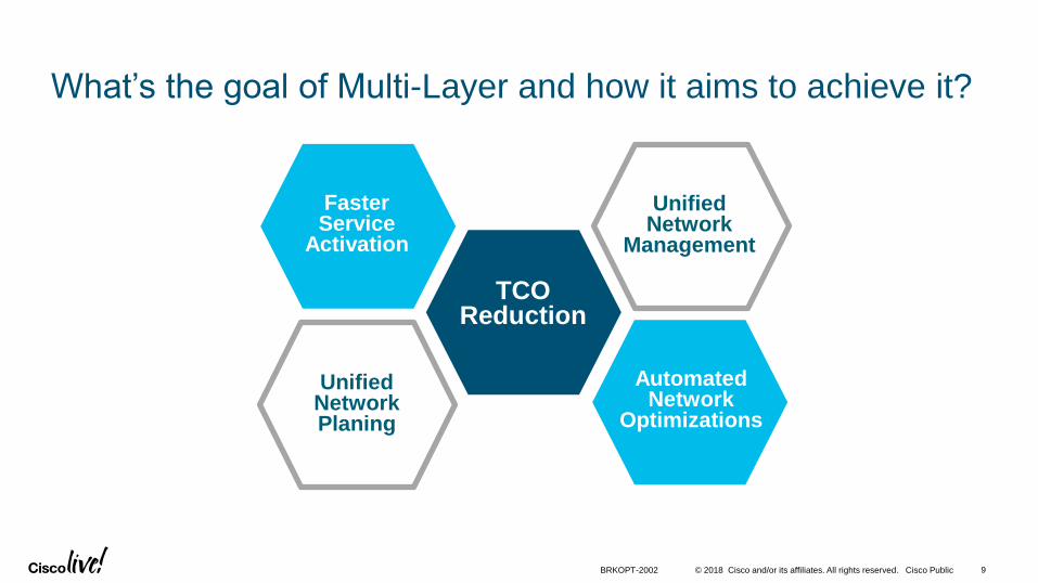
What’s the goal of Multi-Layer and how it aims to achieve it?
TCO Reduction
Faster Service
Activation
Automated Network
Optimizations
Unified Network Planing
Unified Network
Management
BRKOPT-2002 9
© 2018 Cisco and/or its affiliates. All rights reserved. Cisco Public
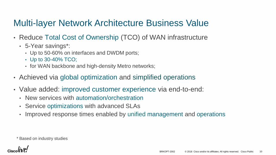
Multi-layer Network Architecture Business Value
• Reduce Total Cost of Ownership (TCO) of WAN infrastructure
• 5-Year savings*:• Up to 50-60% on interfaces and DWDM ports;
• Up to 30-40% TCO;
• for WAN backbone and high-density Metro networks;
• Achieved via global optimization and simplified operations
• Value added: improved customer experience via end-to-end:
• New services with automation/orchestration
• Service optimizations with advanced SLAs
• Improved response times enabled by unified management and operations
10BRKOPT-2002
* Based on industry studies

Converged Multi-Layer Network Architecture
© 2018 Cisco and/or its affiliates. All rights reserved. Cisco Public
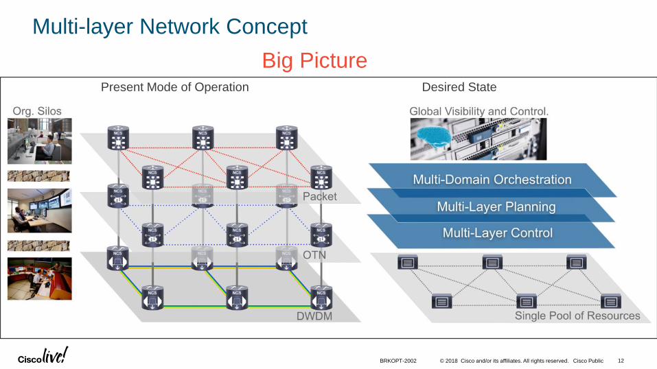
Multi-layer Network Concept
Present Mode of Operation Desired State
Big Picture
BRKOPT-2002 12

© 2018 Cisco and/or its affiliates. All rights reserved. Cisco Public
What’s the problem we are trying to solve?
• Infrastructure inefficiencies:• Over-engineering with overlapping protection – IP and Optical
• Deterministic aggregation of data (statistic) traffic
• Static path assignment to data traffic
• Bandwidth and spectrum fragmentation
• Excessive optical regeneration
• Operational inefficiencies:• Silo’d network planning and operations
• Lack of visibility and coordination across layers
• Lengthy, swivel chair operations
• Complex manual configurations
13BRKOPT-2002

© 2018 Cisco and/or its affiliates. All rights reserved. Cisco Public 14BRKOPT-2002
Network Inefficiencies – a simple example
1+1
50% Efficiency
(1+1)2
25% Efficiency
1+0 1+0
1+1 1+1
IP DWDM DWDM IP
Assumption
Reality
Planning and Provisioning:
Days to weeks
© 2018 Cisco and/or its affiliates. All rights reserved. Cisco Public 15BRKOPT-2002
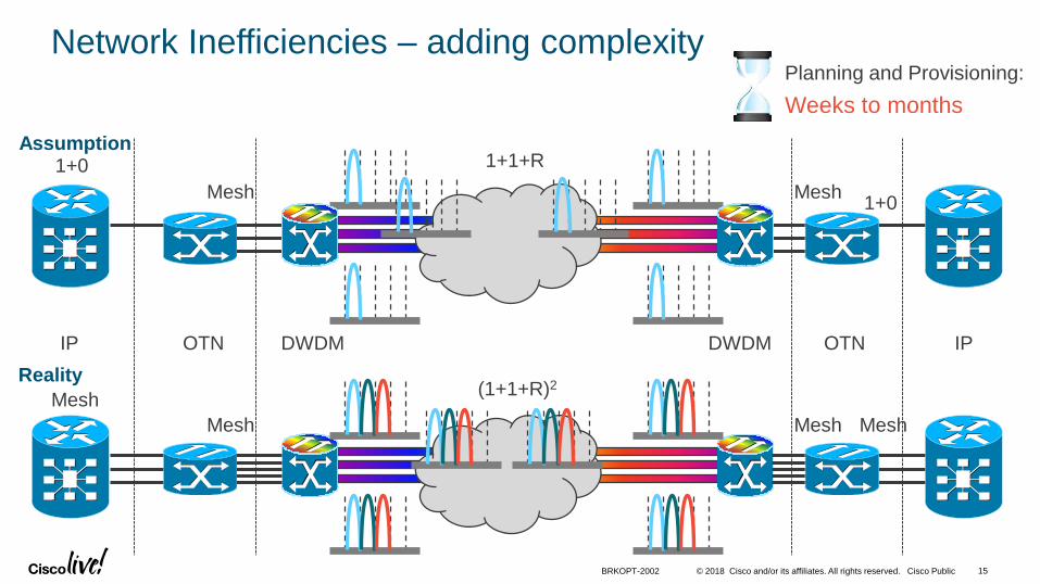
Network Inefficiencies – adding complexity
1+1+R 1+0
1+0
IP DWDM DWDM IPOTN
(1+1+R)2
Mesh
Mesh
OTN
Mesh
Mesh
Mesh
Mesh
Assumption
Reality
Planning and Provisioning:
Weeks to months

© 2018 Cisco and/or its affiliates. All rights reserved. Cisco Public 16BRKOPT-2002
High-level Multi-Layer Architecture
DWDM
OTN
Packet
Controller(s)
Services Orchestration
Applications
PCEP NC/YANG OF SNMP Other APIs
APIs
APIs
EM
S/N
MS
CLI

© 2018 Cisco and/or its affiliates. All rights reserved. Cisco Public 17BRKOPT-2002
High-level Multi-Layer Architecture
• Functional layers:
• Application Layer – advanced traffic engineering, optimization, services creation
• Orchestration Layer – end-to-end services orchestration, automation workflows
• SDN Controller Layer – presents network abstractions to upper layers. May implement control plane functions.
• Network Elements – IP, OTN (optional) and DWDM elements.
• The architecture shall leverage:
• Global view and control for optimizations and activation
• Distributed control plane for fast reaction to local events
• Standard APIs and signaling interfaces as required by network design
DWDM
OTN
Packet
Controller(s)
Services Orchestration
Applications
PCEP NC/YANG OF SNMP Other APIs
APIs
APIs
EM
S/N
MS
CLI
Reference Slide
© 2018 Cisco and/or its affiliates. All rights reserved. Cisco Public
DWDM
OTN
Packet
Controller(s)
Services Orchestration
Applications
PCEP NC/YANG OF SNMP Other APIs
APIs
APIs
EM
S/N
MS
CLI
18BRKOPT-2002
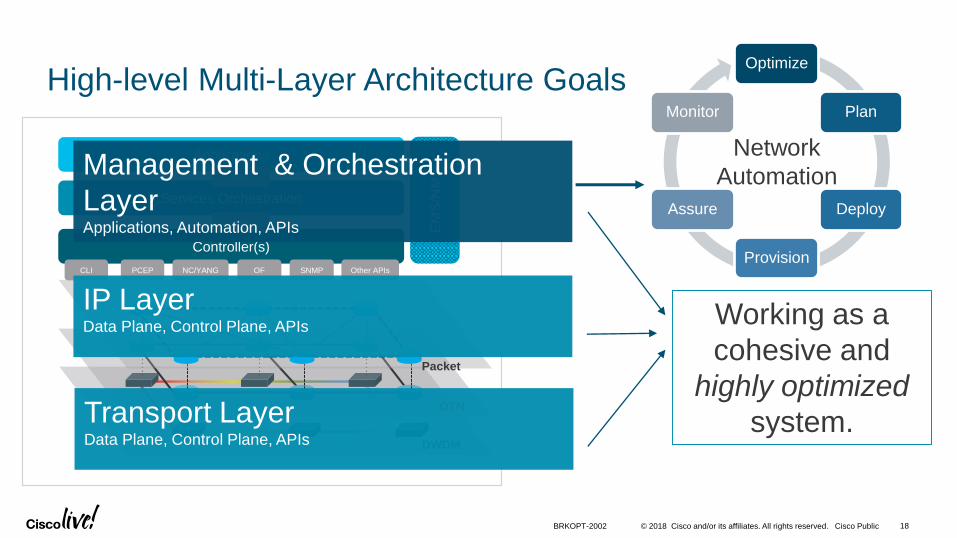
High-level Multi-Layer Architecture Goals
Transport Layer Data Plane, Control Plane, APIs
IP LayerData Plane, Control Plane, APIs
Management & Orchestration
LayerApplications, Automation, APIs
Working as a
cohesive and
highly optimized
system.
Optimize
Plan
Deploy
Provision
Assure
Monitor
Network
Automation
© 2018 Cisco and/or its affiliates. All rights reserved. Cisco Public
DWDM
WSONPacket
IP/MPLS
Multi-Layer Controller(s)
Orchestration
Applications
PCEPNC/
YANGOF SNMP
Other
APIs
APIs
APIs
EM
S/N
MS
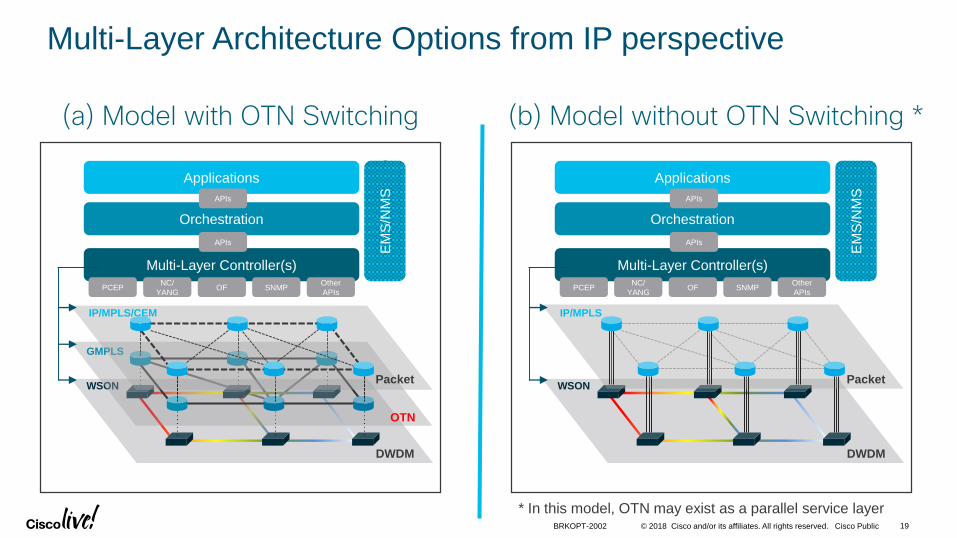
Multi-Layer Architecture Options from IP perspective
(a) Model with OTN Switching
DWDM
WSON
OTN
GMPLS
Packet
IP/MPLS/CEM
Multi-Layer Controller(s)
Orchestration
Applications
PCEPNC/
YANGOF SNMP
Other
APIs
APIs
APIs
EM
S/N
MS
(b) Model without OTN Switching *
BRKOPT-2002 19
* In this model, OTN may exist as a parallel service layer

© 2018 Cisco and/or its affiliates. All rights reserved. Cisco Public 20BRKOPT-2002
IP+Optical Integration Technology Evolution
IPoDWDM
10G/40G
Pro-active
FRR
WSON and
GMPLS UNI
IPoDWDM
100G
Multi-Layer
Planning
Multi-Layer
SDN
Pluggable
DWDM
Routers add support
for DWDM optics
with G.709 framing.
First major
application to
leverage IP+Optical
integration.
Improved network
resiliency/
availability.
Introduction of an advanced
optical control plane to
DWDM networks.
First steps towards end-to-
end automation via cross-
layer signaling.
Simple, focus on
cost reductions.
100G optical costs start
to dominate.
IP+Optical integration
gets more attention.
SDN emerges with
Multi-Layer as use case.
Paradigm shift towards
end-to-end network
solution and global
traffic engineering with
less functional
overlaps.
Virtual
Transponder
Satellite
Optical Shelf
Logical Integration with
unified management.
Major architectural
change:
Global View and
Control for ultimate
network efficiency.
2014
Before 2007 Today
Emerging
© 2018 Cisco and/or its affiliates. All rights reserved. Cisco Public
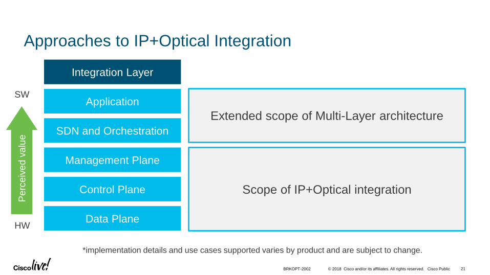
Approaches to IP+Optical Integration
Data Plane
Control Plane
Management Plane
SDN and Orchestration
Application
Integration Layer
Scope of IP+Optical integration
Extended scope of Multi-Layer architecture
BRKOPT-2002 21
*implementation details and use cases supported varies by product and are subject to change.
Perc
eiv
ed v
alu
e
HW
SW
© 2018 Cisco and/or its affiliates. All rights reserved. Cisco Public
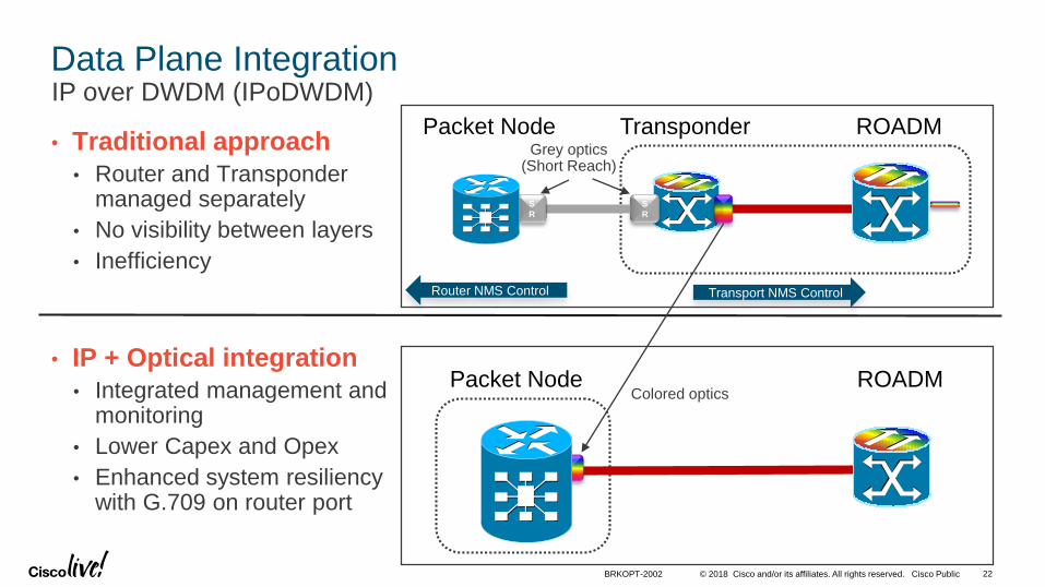
Data Plane IntegrationIP over DWDM (IPoDWDM)
• Traditional approach
• Router and Transponder managed separately
• No visibility between layers
• Inefficiency
Transponder Packet Node
S
R
S
R
ROADM
Transport NMS ControlRouter NMS Control
Packet Node ROADM
BRKOPT-2002
• IP + Optical integration
• Integrated management and monitoring
• Lower Capex and Opex
• Enhanced system resiliency with G.709 on router port
Grey optics(Short Reach)
Colored optics
22
© 2018 Cisco and/or its affiliates. All rights reserved. Cisco Public 23BRKOPT-2002
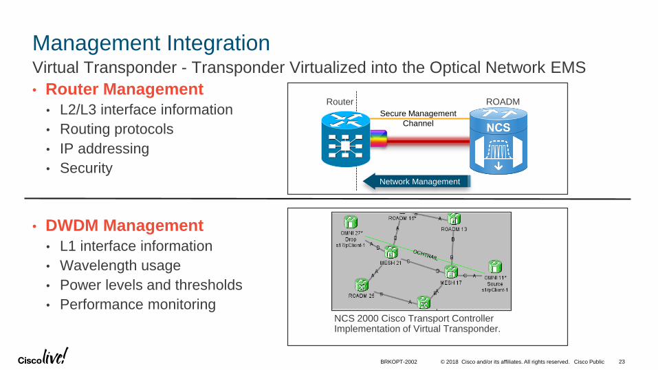
Management IntegrationVirtual Transponder - Transponder Virtualized into the Optical Network EMS
Secure Management
Channel
ROADMRouter
Network Management
NCS 2000 Cisco Transport Controller Implementation of Virtual Transponder.
• Router Management
• L2/L3 interface information
• Routing protocols
• IP addressing
• Security
• DWDM Management
• L1 interface information
• Wavelength usage
• Power levels and thresholds
• Performance monitoring

© 2018 Cisco and/or its affiliates. All rights reserved. Cisco Public 24BRKOPT-2002
Logical Integration
Transponder virtualized as part of the router operational system
• Transponder shelf becomes an extension of the router
• Power levels, OTN overhead, and alarms available in real-time on the router
• DWDM interface controlled and monitored by router
• Control Plane Interaction
Transponder
Optical
ShelfRouter
S
R
Line Card
S
R
ROADM
ShelfSecure
Management
Channel
Grey Optics
Cisco nV Optical Satellite

© 2018 Cisco and/or its affiliates. All rights reserved. Cisco Public 25BRKOPT-2002
Control Plane IntegrationProactive FRR Protection
Reactive Protection
Pre
-FE
C B
it
Err
ors
Ro
ute
r B
it
Err
ors
ROADM
FEC
working
route
protect
route
fail
over
FEC Cliff
LOF
Time
Transponder
Proactive Protection
protect
route
working
route
FEC Cliff
Protection Trigger
Pre
-FE
C B
it
Err
ors
Ro
ute
r B
it
Err
ors
ROADM
SwitchFEC
Time
Router
IP-over-DWDMProactive Protection
Traditional

© 2018 Cisco and/or its affiliates. All rights reserved. Cisco Public
Main Challenges for IP+Optical Integration
• Multi-vendor:
• Proprietary optical interfaces
• Proprietary optical algorithms
• Proprietary management models
• Brownfield deployments
• Organizational alignment (silos)
• Incumbent optical vendor push back
• Professional skills
• Inertia
Technical Non-Technical
Note: most of the technical challenges have been addressed over the years.
BRKOPT-2002 26

© 2018 Cisco and/or its affiliates. All rights reserved. Cisco Public
Multi-Layer Applications
• Broad set of applications enabled by Services Orchestration, SDN/Controllers, APIs and data models
• Examples:
• Multi-layer network planning (growth and what-if scenarios)
• Multi-layer traffic engineering (off-line, on-line)
• Service portals, e.g. bandwidth on demand or calendaring, advanced SLAs based
• Operational applications:• Inventory and fault correlation
• MOP automation
• Closed loop automation
• SRLG avoidance
• Brownfield is possible often requiring systems integration
27BRKOPT-2002

© 2018 Cisco and/or its affiliates. All rights reserved. Cisco Public
• IP+Optical integration:
• Proven and deployed in single vendor and multi-vendor networks for various approaches;
• Studies have shown potential significant cost savings (up to >60% in # of IFs);
• Industry acceptance even by the traditional optical vendors;
• Evolution to Multi-Layer network architecture:
• Industry aligned on general concepts
• Maturing at the speed of SDN, orchestration and SDN applications
• Various implementations and approaches being developed
• Will bring further benefits when it’s fully ready
• Various standardization and open source efforts
State of the Industry for IP+Optical and Multi-Layer
BRKOPT-2002 28
© 2018 Cisco and/or its affiliates. All rights reserved. Cisco Public
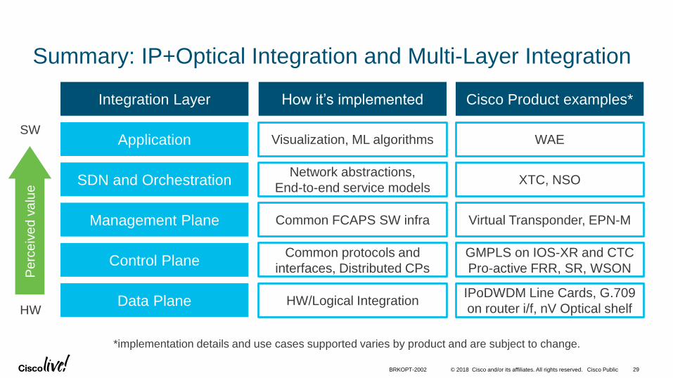
Summary: IP+Optical Integration and Multi-Layer Integration
Data Plane
Control Plane
Management Plane
SDN and Orchestration
Application
IPoDWDM Line Cards, G.709
on router i/f, nV Optical shelf
GMPLS on IOS-XR and CTC
Pro-active FRR, SR, WSON
Virtual Transponder, EPN-M
XTC, NSO
WAE
HW/Logical Integration
Common protocols and
interfaces, Distributed CPs
Common FCAPS SW infra
Network abstractions,
End-to-end service models
Visualization, ML algorithms
Integration Layer Cisco Product examples*How it’s implemented
*implementation details and use cases supported varies by product and are subject to change.
BRKOPT-2002 29
Perc
eiv
ed v
alu
e
HW
SW

Network Design Considerations
© 2018 Cisco and/or its affiliates. All rights reserved. Cisco Public
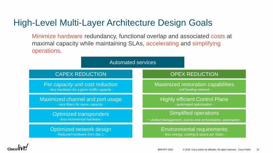
High-Level Multi-Layer Architecture Design Goals
Per capacity unit cost reduction- less hardware for a given traffic capacity -
Maximized channel and port usage- less fibers for same capacity -
Optimized transponders- less incremental hardware -
Optimized network design- Reduced hardware from day 1 -
CAPEX REDUCTION
Maximized restoration capabilities- self healing network -
Highly efficient Control Plane- automated optimization -
Simplified operations
- Unified Management, end-to-end orchestration, automation -
Environmental requirements- less energy, cooling & space per Gbps -
OPEX REDUCTION
Minimize hardware redundancy, functional overlap and associated costs at
maximal capacity while maintaining SLAs, accelerating and simplifying
operations.
BRKOPT-2002 31
Automated services

© 2018 Cisco and/or its affiliates. All rights reserved. Cisco Public
Technology Enablers for Multi-Layer networks
Silicon Flexible Optical LayerSW and Control Plane
High Scale NPUs
High Performance Optical
Channels:• 200G+ Coherent
• DSPs, Flexible modulation
• Adaptive Rates
Distributed + Centralized Intelligence(for both IP and Optical layers – SR + WSON/SSON)
Information Sharing Between Layers (signaling interfaces)
Apps for Optimization and Automation
Network APIs and data models
Complete Flexibility(CCFOS ROADMs)
Programmable
Massive Scale
Programmability, Convergence, and Scale
BRKOPT-2002 32

© 2018 Cisco and/or its affiliates. All rights reserved. Cisco Public
Multi-Layer architecture design General guidelines
1. Design a self-protected, scalable IP/MPLS services layer
2. Build a flexible optical network (e.g. CCOFS ROADM with WSON/SSON)
3. Define integration requirements based on use cases and end-goals
4. Evaluate performance requirements for the optical layer
5. Create a roadmap for SDN-enabled Multi-Layer applications
33BRKOPT-2002

© 2018 Cisco and/or its affiliates. All rights reserved. Cisco Public
IP/MPLS network design considerations
• IP/MPLS as forwarding plane for most L1-L3 transport services:• CEoPS, VPWS, VPLS > EVPN, L3VPN
• QoS for high-priority traffic protection from network congestion• Assumption: during optical restoration (slow) there may be network congestion
• Scalability and resiliency:• Distributed control plane for self-healing
• Centralized control plane for traffic engineering
• SR with TI-LFA: sub-50ms protection for any topology
• BGP PIC Core/Edge
• RFC 3107 BGP-LU, SR-TE
34BRKOPT-2002
1/2

© 2018 Cisco and/or its affiliates. All rights reserved. Cisco Public
IP/MPLS network design considerations
• Programmability and Simplicity:
• Segment Routing
• APIs:• Netconf/YANG
• PCEP
• BGP-LS
• others
• Control plane signaling:
• GMPLS-UNI
35BRKOPT-2002
2/2

© 2018 Cisco and/or its affiliates. All rights reserved. Cisco Public 36BRKOPT-2002
The Foundation is the Dynamic Optical Layer
ROADM
RXTX RXTX
ML Restoration Step 0 – Bend but do
not Break! Protect traffic before failure
allowing near zero packet loss
Shared Risk Link Groups – End to End
circuit provisioning with knowledge of any
Optical infrastructure risks.
Coordinated Maintenance – Provide
proactive notification of maintenance
activity to connected NEs to proactively
route around maintenance node
ML Auto BW – Leverage CP to allow
upper layers to request circuit source and
destination with constraints
ML Restoration Step 1 – Leverage
proactive protection to protect circuit
then leverage CP to restore BW to
network utilizing same interface.
G.709 /
FEC
G.709 /
FEC
Routing
Engine
Routing
Engine
G.7
09 /
FE
C
G.7
09 /
FE
CX
FEC Cliff
FEC thres.
1 2
4 1
5
UNI-C
Diversity / SRLG /
Latency etc…
ROADMXProvide L1 visibility to L3 – L3 can react
to changes in L1
34
FEC Cliff
FEC thres.
Animated Slide
© 2018 Cisco and/or its affiliates. All rights reserved. Cisco Public 37BRKOPT-2002
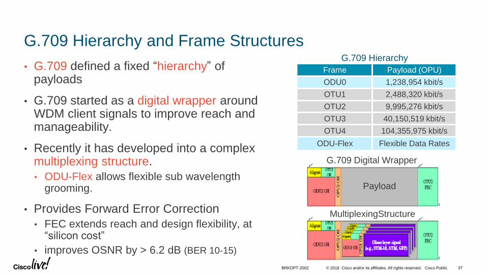
G.709 Hierarchy and Frame Structures
• G.709 defined a fixed “hierarchy” of payloads
• G.709 started as a digital wrapper around WDM client signals to improve reach and manageability.
• Recently it has developed into a complex multiplexing structure.
• ODU-Flex allows flexible sub wavelength grooming.
• Provides Forward Error Correction
• FEC extends reach and design flexibility, at “silicon cost”
• improves OSNR by > 6.2 dB (BER 10-15)
Payload
Frame Payload (OPU)
ODU0 1,238,954 kbit/s
OTU1 2,488,320 kbit/s
OTU2 9,995,276 kbit/s
OTU3 40,150,519 kbit/s
OTU4 104,355,975 kbit/s
ODU-Flex Flexible Data Rates
G.709 Hierarchy
G.709 Digital Wrapper
MultiplexingStructure
© 2018 Cisco and/or its affiliates. All rights reserved. Cisco Public 38
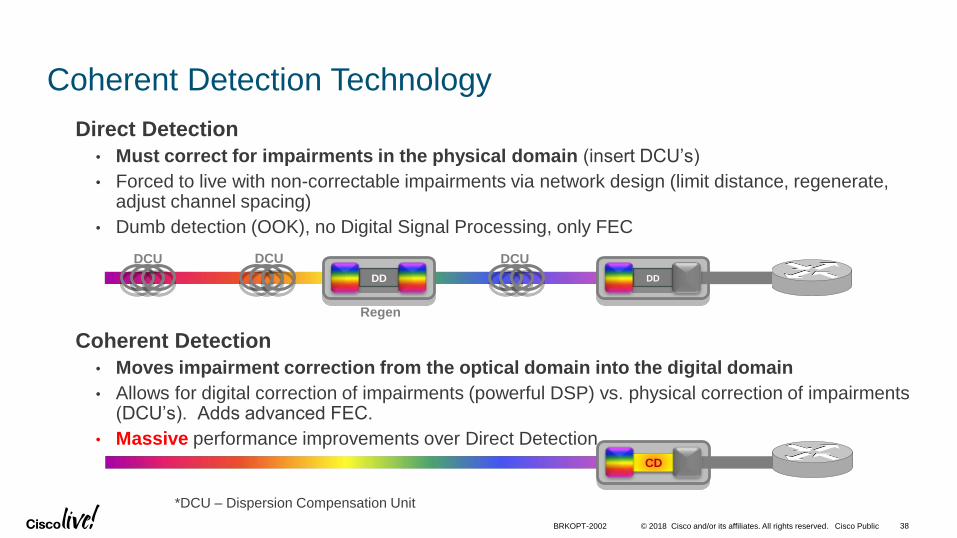
Coherent Detection Technology
Direct Detection
• Must correct for impairments in the physical domain (insert DCU’s)
• Forced to live with non-correctable impairments via network design (limit distance, regenerate, adjust channel spacing)
• Dumb detection (OOK), no Digital Signal Processing, only FEC
Coherent Detection
• Moves impairment correction from the optical domain into the digital domain
• Allows for digital correction of impairments (powerful DSP) vs. physical correction of impairments (DCU’s). Adds advanced FEC.
• Massive performance improvements over Direct Detection.
DDDD
DCU DCU DCU
Regen
CD
*DCU – Dispersion Compensation Unit
BRKOPT-2002

© 2018 Cisco and/or its affiliates. All rights reserved. Cisco Public
Trade off of Reach and Capacity
• Trunk interfaces with
programmable modulation
schemes
• Design algorithm should
choose modulation
schemes to minimize
interface/regenerator
count
BRKOPT-2002 39
© 2018 Cisco and/or its affiliates. All rights reserved. Cisco Public
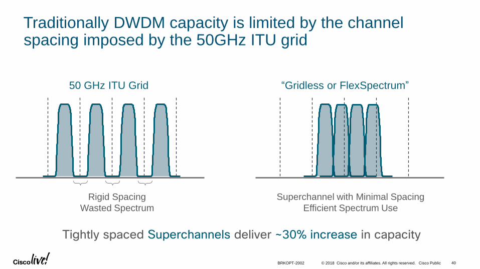
Rigid Spacing
Wasted Spectrum
Superchannel with Minimal Spacing
Efficient Spectrum Use
Tightly spaced Superchannels deliver ~30% increase in capacity
50 GHz ITU Grid “Gridless or FlexSpectrum”
Traditionally DWDM capacity is limited by the channel spacing imposed by the 50GHz ITU grid
40BRKOPT-2002
© 2018 Cisco and/or its affiliates. All rights reserved. Cisco Public
Ch
3Ch3
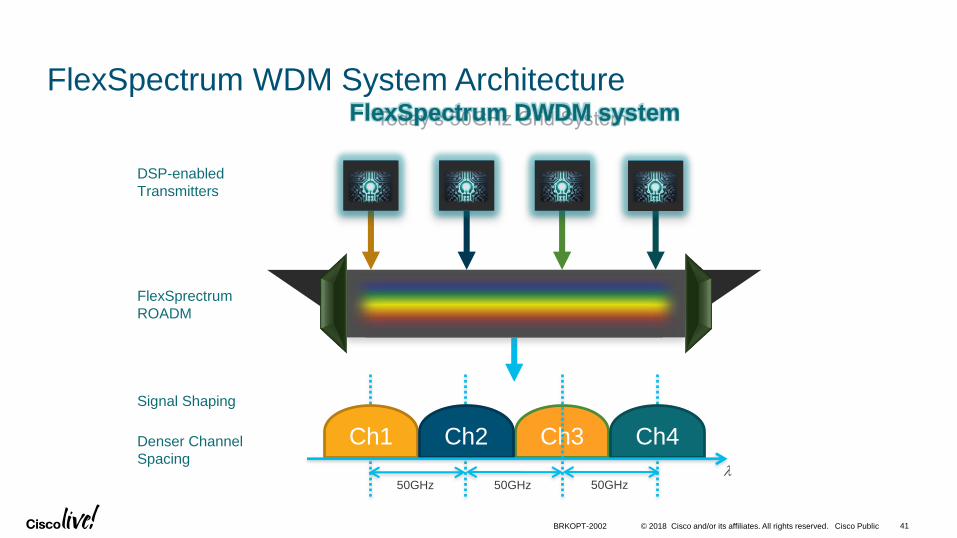
FlexSpectrum WDM System Architecture
50Ghz ROADM
Ch
1
Ch
2
Ch
4
50GHz
Ch1 Ch2 Ch4
50GHz 50GHz
TX
1
TX
2
TX
3
TX
4
Today‘s 50GHz Grid SystemFlexSpectrum DWDM system
l
DSP-enabled
Transmitters
Signal Shaping
FlexSprectrum
ROADM
Denser Channel
Spacing
BRKOPT-2002 41
© 2018 Cisco and/or its affiliates. All rights reserved. Cisco Public
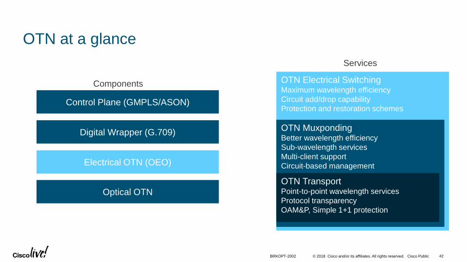
OTN Electrical SwitchingMaximum wavelength efficiency
Circuit add/drop capability
Protection and restoration schemes
OTN MuxpondingBetter wavelength efficiency
Sub-wavelength services
Multi-client support
Circuit-based management
OTN at a glance
Electrical OTN (OEO)
Optical OTN
Digital Wrapper (G.709)
Control Plane (GMPLS/ASON)
OTN TransportPoint-to-point wavelength services
Protocol transparency
OAM&P, Simple 1+1 protection
Components
Services
BRKOPT-2002 42
© 2018 Cisco and/or its affiliates. All rights reserved. Cisco Public
OTN Layer in context of the Multi-Layer Architecture
• OTN G.709 Wrapper:
• Robust encapsulation for TDM and IP interfaces – better OAM and longer distances
• Provides visibility of optical layer to IP layer
• Enables advanced applications like IP+Optical pro-active protection
• Available for both colored and grey interfaces
• Electrical OTN Switching:
• Finer bandwidth granularity to high speed wavelengths
• Cost effective support for high-speed TDM traffic with grooming and dense 3R regeneration
• Use it between if you really need it! - depends on the services mix
• OTN Control Plane (GMPLS):
• Circuit level service restoration over meshed networks (1+R or 1+1+R)
BRKOPT-2002 43
Multilayer Control Plane and SDN Considerations
© 2018 Cisco and/or its affiliates. All rights reserved. Cisco Public
Control Plane Principles
• Distributed control plane is key at both layers, and so is service programmability
• IP/MPLS Control Plane:
• Network programmability - Segment Routing
• Distributed control plane (OSPF/IS-IS) for predictable protection, self-healing and scale
• APIs to centralized software components (BGP-LS, PCEP, Netconf/YANG)
• Optical Control Plane:
• Optical control planes are slow, hence considered only for circuit restoration
• Distributed control plane (WSON) for self-healing and scale
• APIs to centralized software components (Netconf/YANG)
• Cross-layer signaling – GMPLS-UNI
• May not be required with a Multi-Layer controller/application
45BRKOPT-2002
© 2018 Cisco and/or its affiliates. All rights reserved. Cisco Public 46BRKOPT-2002
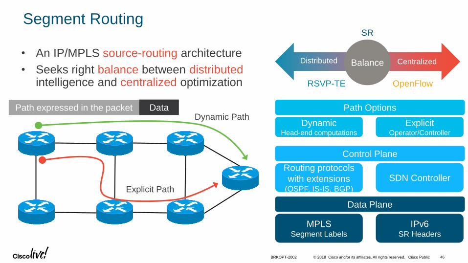
Segment Routing
Path Options
DynamicHead-end computations
ExplicitOperator/Controller
Control Plane
Routing protocols
with extensions(OSPF, IS-IS, BGP)
SDN Controller
Data Plane
MPLSSegment Labels
IPv6SR Headers
• An IP/MPLS source-routing architecture
• Seeks right balance between distributedintelligence and centralized optimization
Path expressed in the packet DataDynamic Path
Explicit Path
RSVP-TE OpenFlow
Balance CentralizedDistributed
SR
© 2018 Cisco and/or its affiliates. All rights reserved. Cisco Public
Wavelength Switched Optical Network - WSON
• WSON is a GMPLS control plane which is “DWDM aware”:
• LSPs are wavelengths;
• Control plane is aware of optical impairments;
• Enables:• Wavelength setup on the fly;
• Wavelength re-routing (restoration – 1+R or 1+1+R);
• Wavelength revalidation against a failure reparation;
• Lowers CAPEX and OPEX of the end-to-end solutions even further;
BRKOPT-2002 47
© 2018 Cisco and/or its affiliates. All rights reserved. Cisco Public
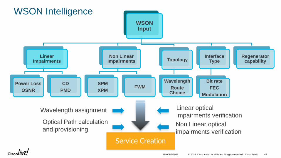
WSON IntelligenceWSON Input
Linear Impairments
Power Loss
OSNR
CD
PMD
Non Linear Impairments
SPM
XPMFWM
Topology
Wavelength
Route Choice
Interface Type
Bit rate
FEC
Modulation
Regenerator capability
Service Creation
Wavelength assignment
Optical Path calculation
and provisioningNon Linear optical
impairments verification
Linear optical
impairments verification
BRKOPT-2002 48
© 2018 Cisco and/or its affiliates. All rights reserved. Cisco Public
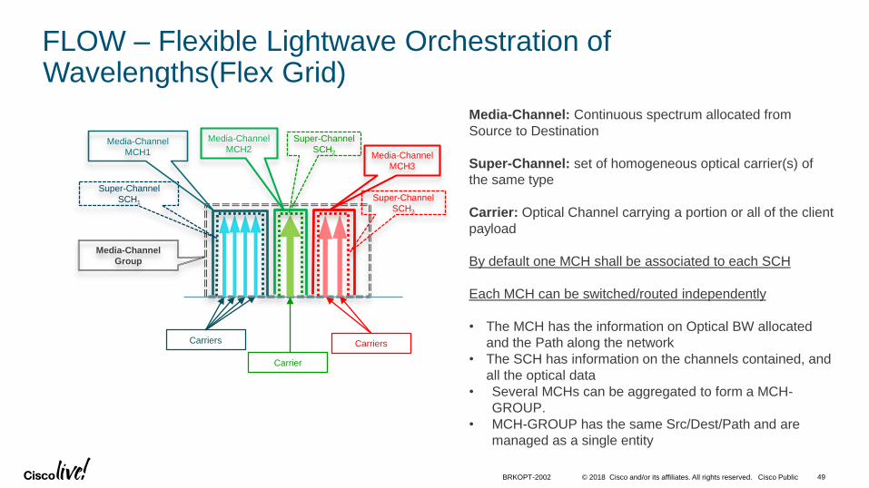
FLOW – Flexible Lightwave Orchestration of Wavelengths(Flex Grid)
49BRKOPT-2002
Media-Channel: Continuous spectrum allocated from
Source to Destination
Super-Channel: set of homogeneous optical carrier(s) of
the same type
Carrier: Optical Channel carrying a portion or all of the client
payload
By default one MCH shall be associated to each SCH
Each MCH can be switched/routed independently
• The MCH has the information on Optical BW allocated
and the Path along the network
• The SCH has information on the channels contained, and
all the optical data
• Several MCHs can be aggregated to form a MCH-
GROUP.
• MCH-GROUP has the same Src/Dest/Path and are
managed as a single entity
Media-Channel
Group
Super-Channel
SCH1
Super-Channel
SCH2
Super-Channel
SCH3
Carriers Carriers
Carrier
Media-Channel
MCH2Media-Channel
MCH3
Media-Channel
MCH1

© 2018 Cisco and/or its affiliates. All rights reserved. Cisco Public
Local Optimization/Global Optimization for WSON
• Minimize the need for intensive optical Impairment calculation
• Develop new Algorithm (LOGO) to deal with complex propagation models of channel in fiber – Simple Analytical Formula
• Interactions of optical signal with fiber during transmission can be modeled as Gaussian Noise, similar to the noise introduced by optical amplification, when some conditions are verified:
• 100G coherent systems
• No Dispersion compensation of fiber link
• Sufficiently dispersive fibers (no DS fiber)
• The noise level depends on fiber characteristics, spectral density on fiber (channel grid) and per-channel power.
BRKOPT-2002 50

© 2018 Cisco and/or its affiliates. All rights reserved. Cisco Public
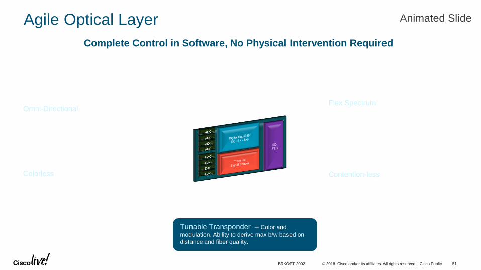
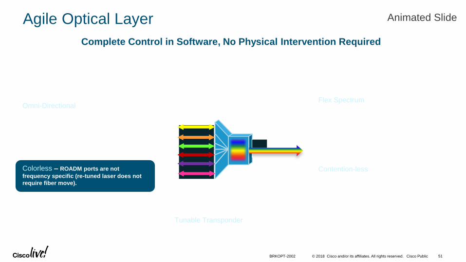
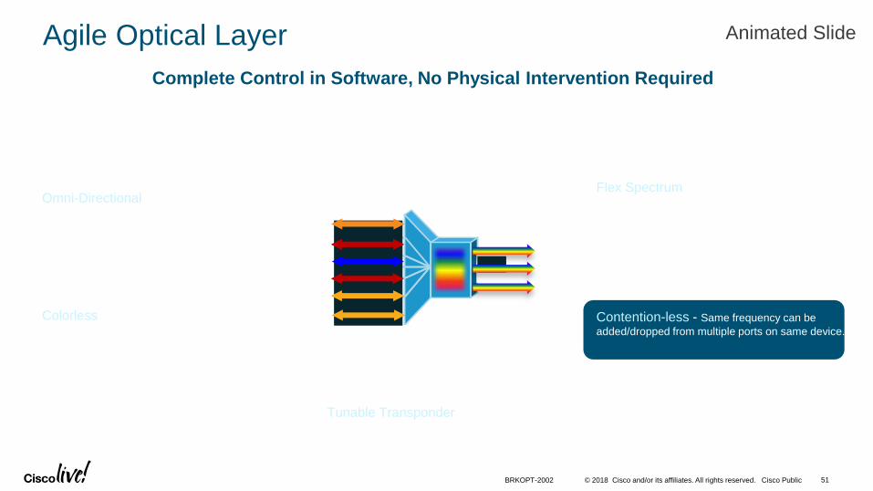
Agile Optical Layer
Colorless – ROADM ports are not
frequency specific (re-tuned laser does not
require fiber move).
Omni-Directional – ROADM ports are not
direction specific (re-route does not require fiber
move).
Contention-less - Same frequency can be
added/dropped from multiple ports on same device.
Flex Spectrum – Ability to provision the
amount of spectrum allocated to wavelength(s)
allowing for 400G and 1T channels.
Complete Control in Software, No Physical Intervention Required
Tunable Transponder – Color and
modulation. Ability to derive max b/w based on
distance and fiber quality.
WSONWavelength Switched Optical Network
Animated Slide
BRKOPT-2002 51
© 2018 Cisco and/or its affiliates. All rights reserved. Cisco Public
Agile Optical Layer
Colorless – ROADM ports are not
frequency specific (re-tuned laser does not
require fiber move).
Omni-Directional – ROADM ports are not
direction specific (re-route does not require fiber
move).
Contention-less - Same frequency can be
added/dropped from multiple ports on same device.
Flex Spectrum – Ability to provision the
amount of spectrum allocated to wavelength(s)
allowing for 400G and 1T channels.
Complete Control in Software, No Physical Intervention Required
Tunable Transponder – Color and
modulation. Ability to derive max b/w based on
distance and fiber quality.
WSONWavelength Switched Optical Network
Animated Slide
BRKOPT-2002 51

© 2018 Cisco and/or its affiliates. All rights reserved. Cisco Public
Agile Optical Layer
Colorless – ROADM ports are not
frequency specific (re-tuned laser does not
require fiber move).
Omni-Directional – ROADM ports are not
direction specific (re-route does not require fiber
move).
Contention-less - Same frequency can be
added/dropped from multiple ports on same device.
Flex Spectrum – Ability to provision the
amount of spectrum allocated to wavelength(s)
allowing for 400G and 1T channels.
Complete Control in Software, No Physical Intervention Required
Foundation for Multi-Layer Network Programmability
Tunable Transponder – Color and
modulation. Ability to derive max b/w based on
distance and fiber quality.
WSONWavelength Switched Optical Network
Animated Slide
BRKOPT-2002 51
© 2018 Cisco and/or its affiliates. All rights reserved. Cisco Public
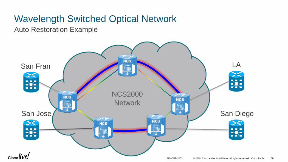
Wavelength Switched Optical NetworkAuto Restoration Example
NCS2000
Network
San Fran
San Jose
LA
San Diego
BRKOPT-2002 58

© 2018 Cisco and/or its affiliates. All rights reserved. Cisco Public
Wavelength Switched Optical NetworkAuto Restoration Example Fiber Cut!
Path San Fran to LA
affected
San Fran
San Jose
LA
San Diego
NCS2000
Network
BRKOPT-2002 59

© 2018 Cisco and/or its affiliates. All rights reserved. Cisco Public
Wavelength Switched Optical NetworkAuto Restoration Example No other path for blue
wavelength - other
wavelengths tried
San Fran
San Jose
LA
San Diego
NCS2000
Network
BRKOPT-2002 60

© 2018 Cisco and/or its affiliates. All rights reserved. Cisco Public
Wavelength Switched Optical NetworkAuto Restoration Example
Embedded WSON intelligence
locates and verifies a new path,
with new lambda
San Fran
San Jose
LA
San Diego
NCS2000
Network
BRKOPT-2002 61
© 2018 Cisco and/or its affiliates. All rights reserved. Cisco Public
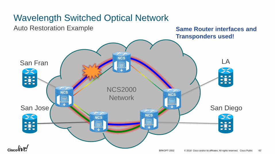
Wavelength Switched Optical NetworkAuto Restoration Example
San Fran
San Jose
Same Router interfaces and
Transponders used!
LA
San Diego
NCS2000
Network
BRKOPT-2002 62

© 2018 Cisco and/or its affiliates. All rights reserved. Cisco Public
Restoration is Slower than Protection
• If rapid failure detection and recovery is needed it is assumed that existing packet IP/ MPLS mechanisms (e.g., BFD, IP-FRR, TE-FRR,LDP-FRR, mLDP-FRR, fast convergence) will be used for protection and recovery.
• IP+Optical Solutions can use Proactive Protection
• Protected services (Y-cable, PSM, FiberSwitch) could be used for valuable traffic to provide rapid protection at the optical layer.
• Restoration is slow (usually minutes)
63BRKOPT-2002
© 2018 Cisco and/or its affiliates. All rights reserved. Cisco Public
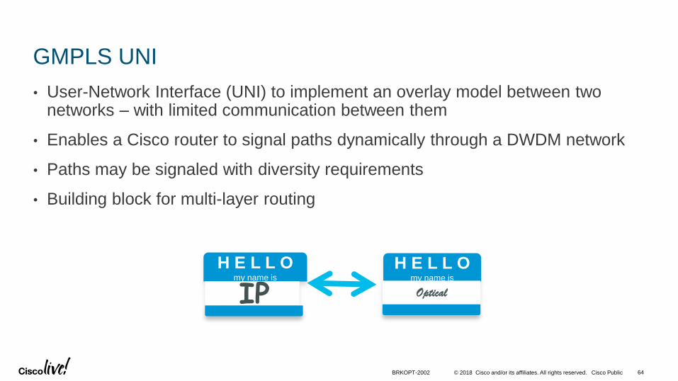
GMPLS UNI
• User-Network Interface (UNI) to implement an overlay model between two networks – with limited communication between them
• Enables a Cisco router to signal paths dynamically through a DWDM network
• Paths may be signaled with diversity requirements
• Building block for multi-layer routing
64BRKOPT-2002
H E L L Omy name is
I IPPH E L L O
my name is
Optical

© 2018 Cisco and/or its affiliates. All rights reserved. Cisco Public
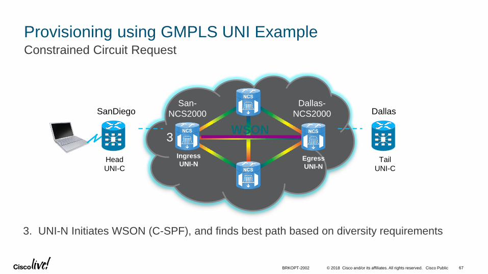
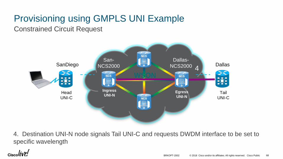
Provisioning using GMPLS UNI ExampleConstrained Circuit Request
1. Operator requests a circuit between Source and Destination Router Interfaces
WSON
SanDiego DallasSan-
NCS2000
Head
UNI-C
Ingress
UNI-N
Dallas-
NCS2000
Tail
UNI-C
Egress
UNI-N
1
BRKOPT-2002 65

© 2018 Cisco and/or its affiliates. All rights reserved. Cisco Public
Provisioning using GMPLS UNI ExampleConstrained Circuit Request
WSON
San-
NCS2000
Head
UNI-C
Ingress
UNI-N
Dallas-
NCS2000
Tail
UNI-C
Egress
UNI-N
2
2. Using GMPLS UNI, Head UNI-C signals UNI-N System requesting path to Destination
SanDiego Dallas
BRKOPT-2002 66
© 2018 Cisco and/or its affiliates. All rights reserved. Cisco Public
Provisioning using GMPLS UNI ExampleConstrained Circuit Request
WSON
San-
NCS2000
Head
UNI-C
Ingress
UNI-N
Dallas-
NCS2000
Tail
UNI-C
Egress
UNI-N
3. UNI-N Initiates WSON (C-SPF), and finds best path based on diversity requirements
3
SanDiego Dallas
BRKOPT-2002 67
© 2018 Cisco and/or its affiliates. All rights reserved. Cisco Public
Provisioning using GMPLS UNI ExampleConstrained Circuit Request
WSON
San-
NCS2000
Head
UNI-C
Ingress
UNI-N
Dallas-
NCS2000
Tail
UNI-C
Egress
UNI-N
4. Destination UNI-N node signals Tail UNI-C and requests DWDM interface to be set to
specific wavelength
4SanDiego Dallas
BRKOPT-2002 68
© 2018 Cisco and/or its affiliates. All rights reserved. Cisco Public
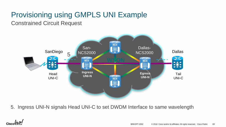
Provisioning using GMPLS UNI ExampleConstrained Circuit Request
WSON
San-
NCS2000
Head
UNI-C
Ingress
UNI-N
Dallas-
NCS2000
Tail
UNI-C
Egress
UNI-N
5. Ingress UNI-N signals Head UNI-C to set DWDM Interface to same wavelength
5SanDiego Dallas
BRKOPT-2002 69

© 2018 Cisco and/or its affiliates. All rights reserved. Cisco Public
Provisioning using GMPLS UNI ExampleConstrained Circuit Request
WSON
San-
NCS2000
Head
UNI-C
Ingress
UNI-N
Dallas-
NCS2000
Tail
UNI-C
Egress
UNI-N
6. Router Interfaces come up, IGP Adjacencies Formed, traffic begins flowing
6
Int Hun0/0/0/0 up/up
ISIS nei relationship
SanDiego Dallas
BRKOPT-2002 70
© 2018 Cisco and/or its affiliates. All rights reserved. Cisco Public
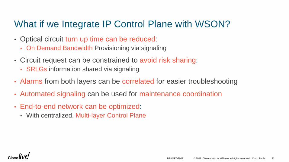
What if we Integrate IP Control Plane with WSON?
• Optical circuit turn up time can be reduced:
• On Demand Bandwidth Provisioning via signaling
• Circuit request can be constrained to avoid risk sharing:
• SRLGs information shared via signaling
• Alarms from both layers can be correlated for easier troubleshooting
• Automated signaling can be used for maintenance coordination
• End-to-end network can be optimized:
• With centralized, Multi-layer Control Plane
BRKOPT-2002 71

© 2018 Cisco and/or its affiliates. All rights reserved. Cisco Public
Extended GMPLS UNI
Optimized for improved L2/L3 Service SLAs and TCO
LFA/TE FRR Fate-
Sharing from primary
WAN
Disjointness
for PoP
Homogenous
Latency and
Fate sharing
Bundle
SLA impact : downtime, latency, loss, predictability of service
TCO impact: SLA penalty, un-optimized capacity, support complexity
BRKOPT-2002 72

© 2018 Cisco and/or its affiliates. All rights reserved. Cisco Public
SRLG
#2
Router ARouter B
[Router A] – “I need a wavelength to Router B.” (basic provisioning)
[Router A] – “I need a wavelength to Router B, disjoint from circuit blue.”
[Router A] – “I need a wavelength to Router B, that avoids SRLG’s #1 and #2.”
SRLG
#1
Constraint Based Routing Example
[Router A] – “I need a wavelength to Router B, with ERO”
BRKOPT-2002 73
© 2018 Cisco and/or its affiliates. All rights reserved. Cisco Public 74BRKOPT-2002
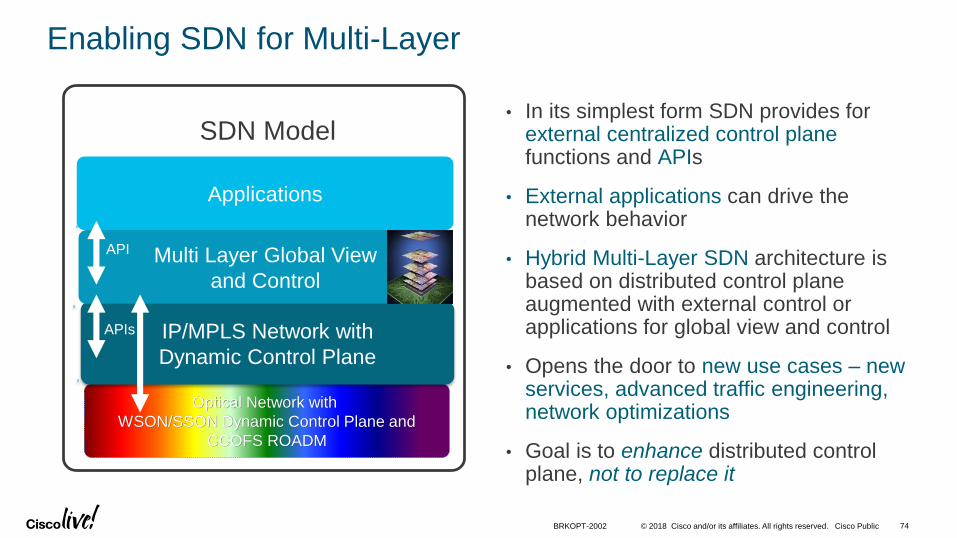
Enabling SDN for Multi-Layer
• In its simplest form SDN provides for external centralized control plane functions and APIs
• External applications can drive the network behavior
• Hybrid Multi-Layer SDN architecture is based on distributed control plane augmented with external control or applications for global view and control
• Opens the door to new use cases – new services, advanced traffic engineering, network optimizations
• Goal is to enhance distributed control plane, not to replace it
Optical Network with
WSON/SSON Dynamic Control Plane and
CCOFS ROADM
IP/MPLS Network with
Dynamic Control Plane
SDN Model
Multi Layer Global View
and Control
Applications
API
APIs
DWDM Layer
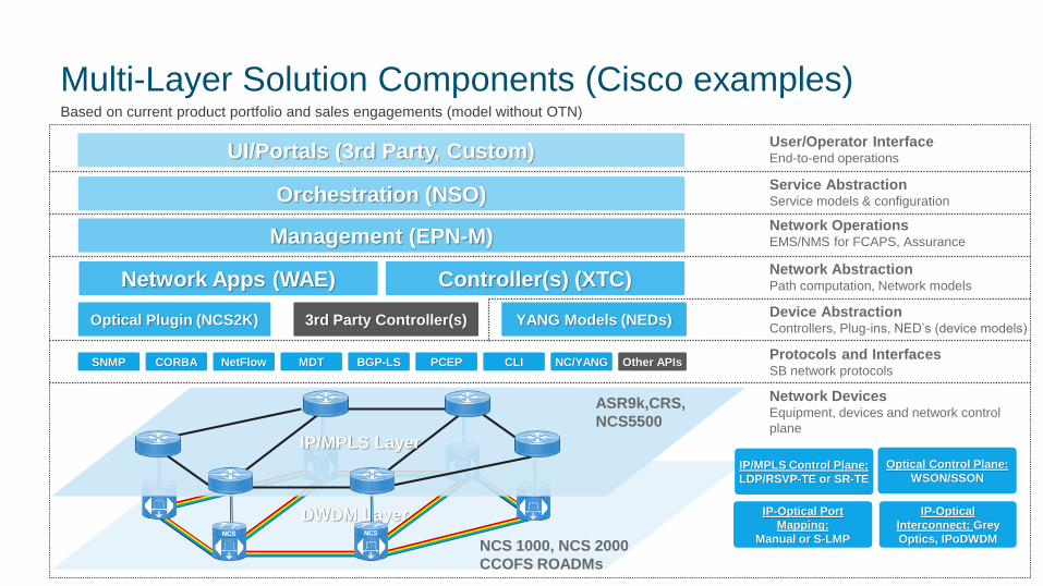
Multi-Layer Solution Components (Cisco examples)Based on current product portfolio and sales engagements (model without OTN)
SNMP NetFlowCORBA
YANG Models (NEDs)
NC/YANGCLIBGP-LS PCEP
Orchestration (NSO)
Network OperationsEMS/NMS for FCAPS, Assurance
Network AbstractionPath computation, Network models
Device AbstractionControllers, Plug-ins, NED’s (device models)
Protocols and InterfacesSB network protocols
Network DevicesEquipment, devices and network control
plane
MDT
UI/Portals (3rd Party, Custom)User/Operator InterfaceEnd-to-end operations
NCS 1000, NCS 2000
CCOFS ROADMs
3rd Party Controller(s)
Optical Control Plane:
WSON/SSON
Optical Plugin (NCS2K)
Network Apps (WAE) Controller(s) (XTC)
Management (EPN-M)
Service AbstractionService models & configuration
ASR9k,CRS,
NCS5500
IP/MPLS Control Plane:
LDP/RSVP-TE or SR-TE
IP-Optical Port
Mapping:
Manual or S-LMP
IP-Optical
Interconnect: Grey
Optics, IPoDWDM
IP/MPLS Layer
Other APIs
© 2018 Cisco and/or its affiliates. All rights reserved. Cisco Public
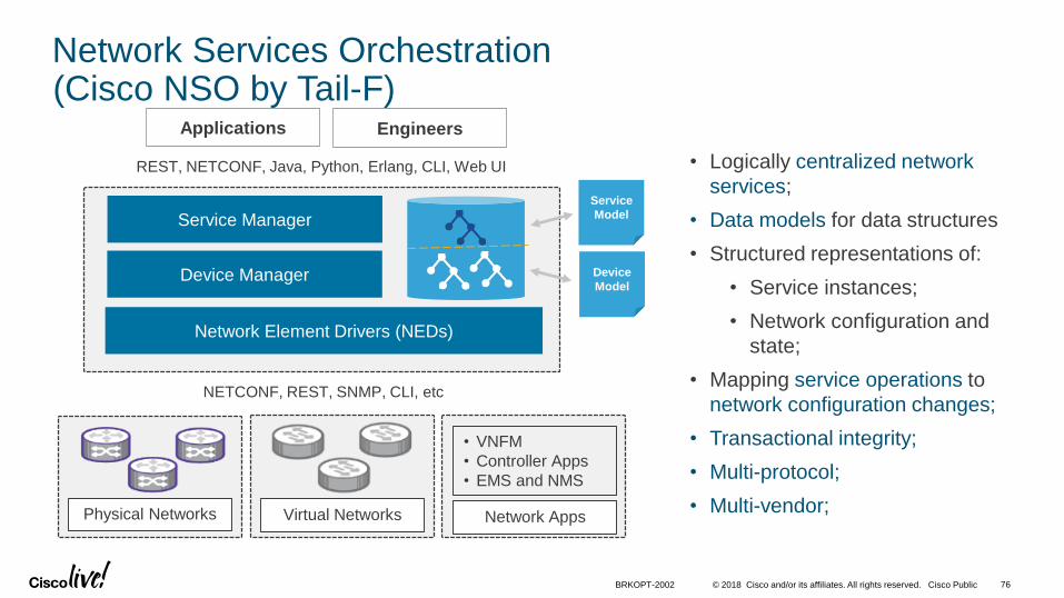
Network Services Orchestration(Cisco NSO by Tail-F)
Network Element Drivers (NEDs)
Service Manager
Device Manager
Physical Networks Virtual Networks
• VNFM
• Controller Apps
• EMS and NMS
Network Apps
Service
Model
Device
Model
Applications
REST, NETCONF, Java, Python, Erlang, CLI, Web UI
NETCONF, REST, SNMP, CLI, etc
Engineers
• Logically centralized network
services;
• Data models for data structures
• Structured representations of:
• Service instances;
• Network configuration and
state;
• Mapping service operations to
network configuration changes;
• Transactional integrity;
• Multi-protocol;
• Multi-vendor;
BRKOPT-2002 76
© 2018 Cisco and/or its affiliates. All rights reserved. Cisco Public
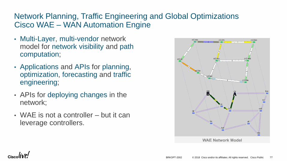
Network Planning, Traffic Engineering and Global OptimizationsCisco WAE – WAN Automation Engine
• Multi-Layer, multi-vendor network model for network visibility and path computation;
• Applications and APIs for planning, optimization, forecasting and traffic engineering;
• APIs for deploying changes in the network;
• WAE is not a controller – but it can leverage controllers.
BRKOPT-2002 77

© 2018 Cisco and/or its affiliates. All rights reserved. Cisco Public
SR-PCE
IP/MPLS Path ComputationCisco XTC – XR Transport Controller
• An XR-powered Statefull Path Computation Element (PCE);
• Multi-domain topology collection with real-time reactive feed;
• Path computation:
• Native SR-TE algorithms;
• Applicable to centralized and distributedcontrollers.
Multi-domain
TopologyComputation
Northbound API
Collection
BGP-LS
IS-IS/OSPF
Deployment
PCEP
BRKOPT-2002 78
© 2018 Cisco and/or its affiliates. All rights reserved. Cisco Public
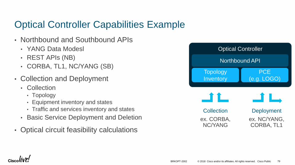
Optical Controller
Optical Controller Capabilities Example
• Northbound and Southbound APIs
• YANG Data Modesl
• REST APIs (NB)
• CORBA, TL1, NC/YANG (SB)
• Collection and Deployment
• Collection• Topology
• Equipment inventory and states
• Traffic and services inventory and states
• Basic Service Deployment and Deletion
• Optical circuit feasibility calculations
Topology
Inventory
PCE
(e.g. LOGO)
Northbound API
Collection
ex. CORBA, NC/YANG
Deployment
ex. NC/YANG, CORBA, TL1
BRKOPT-2002 79
© 2018 Cisco and/or its affiliates. All rights reserved. Cisco Public
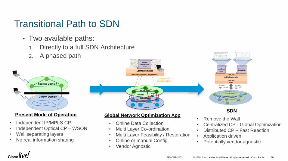
Transitional Path to SDN
• Two available paths:
1. Directly to a full SDN Architecture
2. A phased path
Rou ngDomain
DWDMDomain
• Independent IP/MPLS CP
• Independent Optical CP – WSON
• Wall separating layers
• No real information sharing
Present Mode of Operation
• Online Data Collection
• Multi Layer Co-ordination
• Multi Layer Feasibility / Restoration
• Online or manual Config
• Vendor Agnostic
Global Network Optimization App• Remove the Wall
• Centralized CP - Global Optimization
• Distributed CP – Fast Reaction
• Application driven
• Potentially vendor agnostic
SDN
CLI/TL1/SNMP/NetConfUNI..
OF/PCEP/I2RS/TL-1/UNI
UnifiedController
OpenAPIs
PlugIn
BWCalendaring
orNOS
PrimeCarrierManagement
OpenAPIs
PacketLayer
Op calLayer
x
Op onal:PushConfignLight
CentralCompute
NetworkCollec on/“Deployment”
NetworkOp miza on
Server
nLightERO
WSON
IP/MPLS
Option push configurations
BRKOPT-2002 80

Use Cases and Benefits

© 2018 Cisco and/or its affiliates. All rights reserved. Cisco Public
Use Cases for Multi-Layer Networks
Network ManagementMulti-layer management, data collection, analysis, correlation.
Single pane of glass for end-to-end network visualization.
Intelligent Service ActivationMulti-layer traffic engineering, constraint-based routing.
Optical network aware, on-demand or scheduled services.
Network OptimizationMulti-layer planning, what-if analysis and design across layers.
Online automated optimization across layers.
Coordinated RestorationMulti-layer restoration, IP protection plus optical restoration.
Re-use stranded network assets.
Bett
er
As
se
t U
tili
za
tio
nBe
ne
fit
Op
era
tio
n E
ffic
ien
cy
BRKOPT-2002 82
© 2018 Cisco and/or its affiliates. All rights reserved. Cisco Public
PacketLayer
Op calLayer
NOS(FormerlyMate)
SNMP/API
x
PRIME
nLightERO
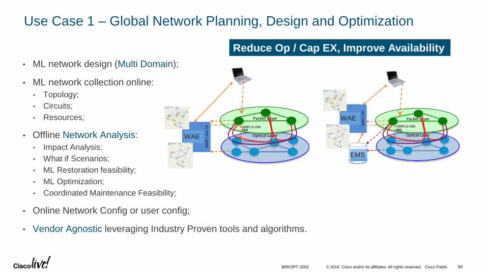
Use Case 1 – Global Network Planning, Design and Optimization
• ML network design (Multi Domain);
• ML network collection online:
• Topology;
• Circuits;
• Resources;
• Offline Network Analysis:
• Impact Analysis;
• What if Scenarios;
• ML Restoration feasibility;
• ML Optimization;
• Coordinated Maintenance Feasibility;
• Online Network Config or user config;
• Vendor Agnostic leveraging Industry Proven tools and algorithms.
PacketLayer
Op calLayerNOS
(FormerlyMate)
SNMP/JavaLib
x
nLightERO
Reduce Op / Cap EX, Improve Availability
WAE
WAE
EMS
BRKOPT-2002 83
GMPLS-UNI GMPLS-UNI
© 2018 Cisco and/or its affiliates. All rights reserved. Cisco Public
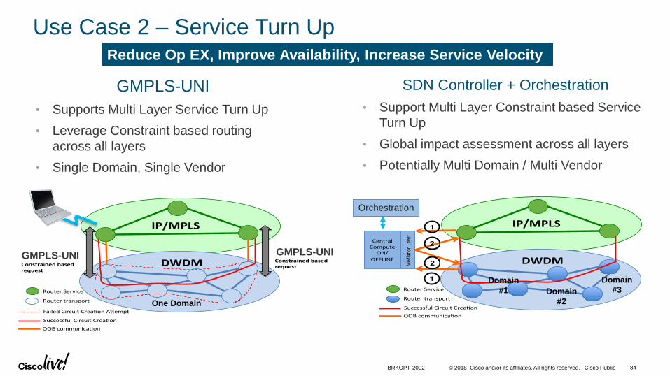
Use Case 2 – Service Turn Up
GMPLS-UNI
• Supports Multi Layer Service Turn Up
• Leverage Constraint based routing
across all layers
• Single Domain, Single Vendor
IP/MPLS
DWDMnLightConstrainedbasedrequest
RouterService
Routertransport
nLightConstrainedbasedrequest
FailedCircuitCrea onA empt
SuccessfulCircuitCrea on
OOBcommunica on
1
2
2
1
SDN Controller + Orchestration
• Support Multi Layer Constraint based Service
Turn Up
• Global impact assessment across all layers
• Potentially Multi Domain / Multi Vendor
One Domain
Domain
#1 Domain
#2
Domain
#3
Reduce Op EX, Improve Availability, Increase Service Velocity
Orchestration
BRKOPT-2002 84
GMPLS-UNIGMPLS-UNI
© 2018 Cisco and/or its affiliates. All rights reserved. Cisco Public
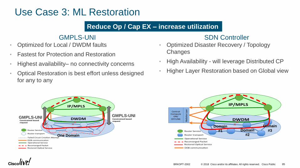
Use Case 3: ML Restoration
IP/MPLS
DWDMnLightConstrainedbasedrequest
RouterService
Routertransport
nLightConstrainedbasedrequest
FailedCircuitCrea onA empt
OOBcommunica on
XX
Opera onalService
ReconvergedPacket
RestoredOp calService
GMPLS-UNI• Optimized for Local / DWDM faults
• Fastest for Protection and Restoration
• Highest availability– no connectivity concerns
• Optical Restoration is best effort unless designed
for any to any
SDN Controller• Optimized Disaster Recovery / Topology
Changes
• High Availability - will leverage Distributed CP
• Higher Layer Restoration based on Global view
One Domain
Domain
#1 Domain
#2
Domain
#3
Reduce Op / Cap EX – increase utilization
BRKOPT-2002 85
GMPLS-UNI GMPLS-UNI
© 2018 Cisco and/or its affiliates. All rights reserved. Cisco Public
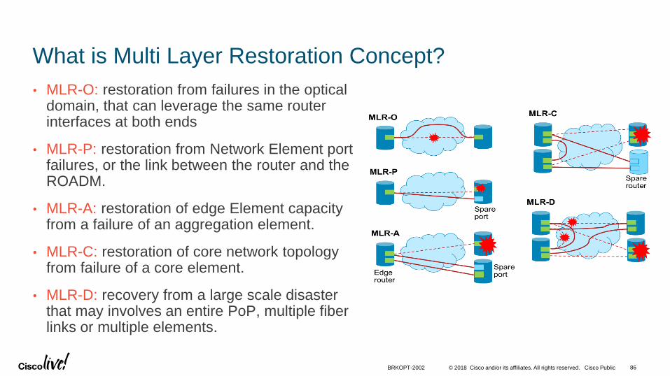
What is Multi Layer Restoration Concept?
• MLR-O: restoration from failures in the optical domain, that can leverage the same router interfaces at both ends
• MLR-P: restoration from Network Element port failures, or the link between the router and the ROADM.
• MLR-A: restoration of edge Element capacity from a failure of an aggregation element.
• MLR-C: restoration of core network topology from failure of a core element.
• MLR-D: recovery from a large scale disaster that may involves an entire PoP, multiple fiber links or multiple elements.
BRKOPT-2002 86
© 2018 Cisco and/or its affiliates. All rights reserved. Cisco Public
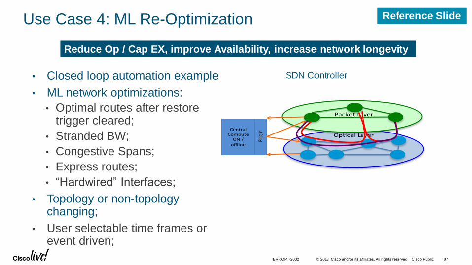
Use Case 4: ML Re-Optimization
• Closed loop automation example
• ML network optimizations:
• Optimal routes after restore trigger cleared;
• Stranded BW;
• Congestive Spans;
• Express routes;
• “Hardwired” Interfaces;
• Topology or non-topology changing;
• User selectable time frames or event driven;
PacketLayer
Op calLayerCentralComputeON/offline
Plugin
Reduce Op / Cap EX, improve Availability, increase network longevity
SDN Controller
BRKOPT-2002 87
Reference Slide
© 2018 Cisco and/or its affiliates. All rights reserved. Cisco Public
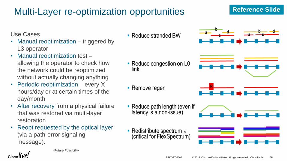
Multi-Layer re-optimization opportunities
Use Cases
• Manual reoptimization – triggered by
L3 operator
• Manual reoptimization test –
allowing the operator to check how
the network could be reoptimized
without actually changing anything
• Periodic reoptimization – every X
hours/day or at certain times of the
day/month
• After recovery from a physical failure
that was restored via multi-layer
restoration
• Reopt requested by the optical layer
(via a path-error signaling
message).
*Future Possibility
*
BRKOPT-2002 88
Reference Slide

© 2018 Cisco and/or its affiliates. All rights reserved. Cisco Public
Use Case 5: Co-ordinated Maintenance
• Select maintenance node;
• Verify level of service impact by maintenance event;
• Route traffic around affected node:
• Wavelength and Packet;
• Notify time to start event;
• Restore traffic once maintenance complete.
PacketLayer
Op calLayerCentralComputeON/offline
Plugin
x
Reduce Op EX, improve Availability, improve SLAs
BRKOPT-2002 89
Reference Slide

© 2018 Cisco and/or its affiliates. All rights reserved. Cisco Public 90BRKOPT-2002
Multi-Layer Network Business Benefits
0%
10%
20%
30%
40%
50%
60%
70%
80%
90%
100%
DTyear1 DTyear5 TEFyear1 TEFyear5
Baseline
MLBO
MLBO+MLR-O
MLBO+MLR-O+MLR-P
IEEE Communication Magazine Jan-Feb 2014
~60% interface savings
Up to 60% interface savings as
capacty increases

© 2018 Cisco and/or its affiliates. All rights reserved. Cisco Public 91BRKOPT-2002
Multilayer Optimization vs Single-layer Optimization Reference: IEEE OFC 2015 M. Khaddam (Thursday 8 am, invited)
SDN
Controller EMS
Applications
(Multi-layer, SPRING, etc)
WDM
Client

Summary

• Industry trends
• Converged Multi-Layer network architecture
• Network design considerations
• Control Plane and SDN considerations
• Use cases and benefits
Recap

© 2018 Cisco and/or its affiliates. All rights reserved. Cisco Public 94BRKOPT-2002
Summary: It’s all about convergence!
Logical or Physical Convergence
Why?
• End-to-end Efficiency:
• Sharing relevant information across layers, global view and control;
• Network Agility:
• Automation, dynamic services capabilities, programmability;
• Operational Simplicity:
• Control plane simplifications, control plane integration, APIs;
• Major Business Benefits are there:
• Up to 45%+ TCO savings*.
*Based on Cisco and industry studies.
DWDM
OTN
Packet
Controller(s)
Services Orchestration
Applications
PCEP NC/YANG OF SNMP Other APIs
APIs
APIs
EM
S/N
MS
CLI

© 2018 Cisco and/or its affiliates. All rights reserved. Cisco Public
Approaches to IP+Optical Integration
Data Plane
Control Plane
Management Plane
SDN and Orchestration
Application
Integration Layer
Scope of IP+Optical integration
Extended scope of Multi-Layer architecture
BRKOPT-2002 95
*implementation details and use cases supported varies by product and are subject to change.
Perc
eiv
ed v
alu
e
HW
SW
© 2018 Cisco and/or its affiliates. All rights reserved. Cisco Public
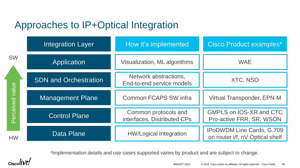
Approaches to IP+Optical Integration
96BRKOPT-2002
Data Plane
Control Plane
Management Plane
SDN and Orchestration
Application
IPoDWDM Line Cards, G.709
on router i/f, nV Optical shelf
GMPLS on IOS-XR and CTC
Pro-active FRR, SR, WSON
Virtual Transponder, EPN-M
XTC, NSO
WAE
HW/Logical Integration
Common protocols and
interfaces, Distributed CPs
Common FCAPS SW infra
Network abstractions,
End-to-end service models
Visualization, ML algorithms
Integration Layer Cisco Product examples*How it’s implemented
*implementation details and use cases supported varies by product and are subject to change.
Perc
eiv
ed v
alu
e
HW
SW

© 2018 Cisco and/or its affiliates. All rights reserved. Cisco Public
Cisco Spark
Questions? Use Cisco Spark to communicate with the speaker after the session
1. Find this session in the Cisco Live Mobile App
2. Click “Join the Discussion”
3. Install Spark or go directly to the space
4. Enter messages/questions in the space
How
cs.co/ciscolivebot#BRKOPT-2002

© 2018 Cisco and/or its affiliates. All rights reserved. Cisco Public
• Please complete your Online Session Evaluations after each session
• Complete 4 Session Evaluations & the Overall Conference Evaluation (available from Thursday) to receive your Cisco Live T-shirt
• All surveys can be completed via the Cisco Live Mobile App or the Communication Stations
Don’t forget: Cisco Live sessions will be available for viewing on-demand after the event at www.ciscolive.com/global/on-demand-library/.
Complete Your Online Session Evaluation

© 2018 Cisco and/or its affiliates. All rights reserved. Cisco Public
Continue Your Education
• Demos in the Cisco campus
• Walk-in Self-Paced Labs
• Tech Circle
• Meet the Engineer 1:1 meetings
• Related sessions
99BRKOPT-2002

Thank you

© 2018 Cisco and/or its affiliates. All rights reserved. Cisco Public
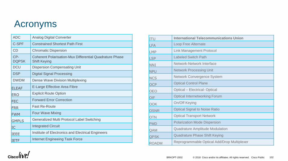
Acronyms
ADC Analog Digital Converter
C-SPF Constrained Shortest Path First
CD Chromatic Dispersion
CP-
DQPSK
Coherent Polarisation-Mux Differential Quadrature Phase
Shift Keying
DCU Dispersion Compensating Unit
DSP Digital Signal Processing
DWDM Dense Wave Division Multiplexing
ELEAF E-Large Effective Area Fibre
ERO Explicit Route Option
FEC Forward Error Correction
FRR Fast Re-Route
FWM Four Wave Mixing
GMPLS Generalized Multi Protocol Label Switching
IC Integrated Circuit
IEEE Institute of Electronics and Electrical Engineers
IETF Internet Engineeing Task Force
ITU International Telecommunications Union
LFA Loop Free Alternate
LMP Link Management Protocol
LSP Labeled Switch Path
NNI Network-Network Interface
NPU Network Processing Unit
NCS Network Convergence System
OCP Optical Control Plane
OEO Optical – Electrical- Optical
OIF Optical Internetworking Forum
OOK On/Off Keying
OSNR Optical Signal to Noise Ratio
OTN Optical Transport Network
PMD Polarization Mode Dispersion
QAM Quadrature Amplitude Modulation
QPSK Quadrature Phase Shift Keying
ROADM Reprogrammable Optical Add/Drop Multiplexer
BRKOPT-2002 102

© 2018 Cisco and/or its affiliates. All rights reserved. Cisco Public
Acronyms (Continued)
RSVP Resource Reservation Protocol
SDH Synchronous Digital Hierarchy
SLA Service Level Agreement
SMF
Single Mode Fiber
SONET Synchronous Optical Network
SRLG Shared Risk Link Groups
TCO Total Cost of Ownership
TDM Time Division Multiplexed
TE Traffic Engineering
UNI User-Network Interface
WSON Wavelength Switched Optical Network
WXC Wavelength Cross Connect
XPM Cross Phase Modulation
YoY Year over Year
BRKOPT-2002 103