
Cisco IP Phone Key Expansion Module - mun.ca · Step 9...
14
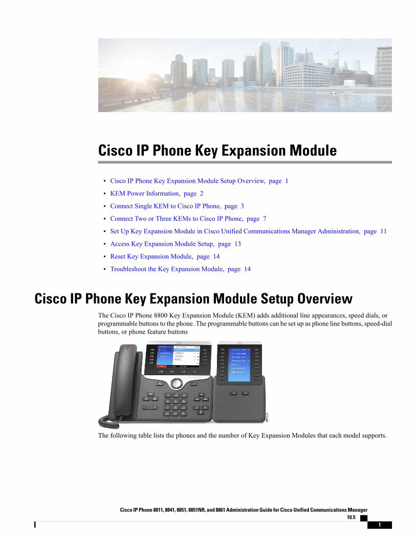
Cisco IP Phone Key Expansion Module • Cisco IP Phone Key Expansion Module Setup Overview, page 1 • KEM Power Information, page 2 • Connect Single KEM to Cisco IP Phone, page 3 • Connect Two or Three KEMs to Cisco IP Phone, page 7 • Set Up Key Expansion Module in Cisco Unified Communications Manager Administration, page 11 • Access Key Expansion Module Setup, page 13 • Reset Key Expansion Module, page 14 • Troubleshoot the Key Expansion Module, page 14 Cisco IP Phone Key Expansion Module Setup Overview The Cisco IP Phone 8800 Key Expansion Module (KEM) adds additional line appearances, speed dials, or programmable buttons to the phone. The programmable buttons can be set up as phone line buttons, speed-dial buttons, or phone feature buttons The following table lists the phones and the number of Key Expansion Modules that each model supports. Cisco IP Phone 8811, 8841, 8851, 8851NR, and 8861 Administration Guide for Cisco Unified Communications Manager 10.5 1
Transcript of Cisco IP Phone Key Expansion Module - mun.ca · Step 9...
Cisco IP Phone Key Expansion Module
• Cisco IP Phone Key Expansion Module Setup Overview, page 1
• KEM Power Information, page 2
• Connect Single KEM to Cisco IP Phone, page 3
• Connect Two or Three KEMs to Cisco IP Phone, page 7
• Set Up Key Expansion Module in Cisco Unified Communications Manager Administration, page 11
• Access Key Expansion Module Setup, page 13
• Reset Key Expansion Module, page 14
• Troubleshoot the Key Expansion Module, page 14
Cisco IP Phone Key Expansion Module Setup OverviewThe Cisco IP Phone 8800 Key Expansion Module (KEM) adds additional line appearances, speed dials, orprogrammable buttons to the phone. The programmable buttons can be set up as phone line buttons, speed-dialbuttons, or phone feature buttons
The following table lists the phones and the number of Key Expansion Modules that each model supports.
Cisco IP Phone 8811, 8841, 8851, 8851NR, and 8861 Administration Guide for Cisco Unified Communications Manager10.5
1
Table 1: Cisco IP Phones and Supported KEMs
Supported KEMsCisco IP Phone model
2 KEMs with 72 lines or buttonsCisco IP Phone 8851 and 8851NR
3 KEMs with 108 lines or buttonsCisco IP Phone 8861
Related Topics
Wall Mounts
KEM Power InformationThe Cisco IP Phone 8800 Key Expansion Module possesses the following power consumption and powerscheme:
Power consumption
48V DC, 5W per KEM
Power scheme
The phone can power one KEM directly. For more information, see the following table.
Table 2: Key Expansion Module Power
Cisco IP Phone 8861Cisco IP Phone 8851 and 8851NR
Cisco IP PhonePower Cube 4
802.3at PoE802.3af PoECisco IP PhonePower Cube 4
802.3at PoE802.3af PoEAccessories
SupportedSupportedNot supportedSupportedSupportedSupported1 KEM
SupportedSupportedNot supportedSupportedNot supportedNot supported2 KEM
SupportedSupportedNot supportedNot supportedNot supportedNot supported3 KEM
SupportedSupportedNot supportedNot supportedNot supportedNot supported1 KEM +tabletcharging
SupportedNot supportedNot supportedNot supportedNot supportedNot supported2 KEM +tabletcharging
SupportedNot supportedNot supportedNot supportedNot supportedNot supported3 KEM +tabletcharging
Cisco IP Phone 8811, 8841, 8851, 8851NR, and 8861 Administration Guide for Cisco Unified CommunicationsManager 10.5
2
Cisco IP Phone Key Expansion ModuleKEM Power Information
When more than one KEM is attached to the Cisco IP Phone 8861, the fast-charge feature using the backUSB port is not supported. In this scenario, the back port will slow-charge the device.
Note
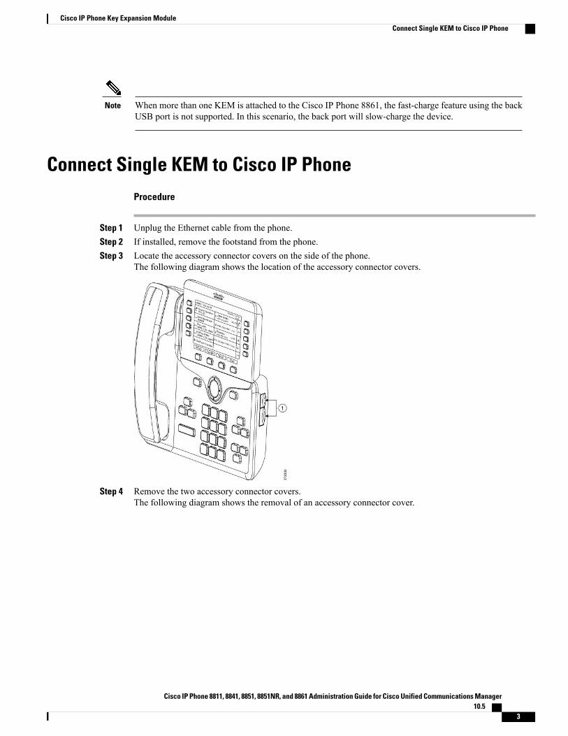
Connect Single KEM to Cisco IP PhoneProcedure
Step 1 Unplug the Ethernet cable from the phone.Step 2 If installed, remove the footstand from the phone.Step 3 Locate the accessory connector covers on the side of the phone.
The following diagram shows the location of the accessory connector covers.
Step 4 Remove the two accessory connector covers.The following diagram shows the removal of an accessory connector cover.
Cisco IP Phone 8811, 8841, 8851, 8851NR, and 8861 Administration Guide for Cisco Unified Communications Manager10.5
3
Cisco IP Phone Key Expansion ModuleConnect Single KEM to Cisco IP Phone
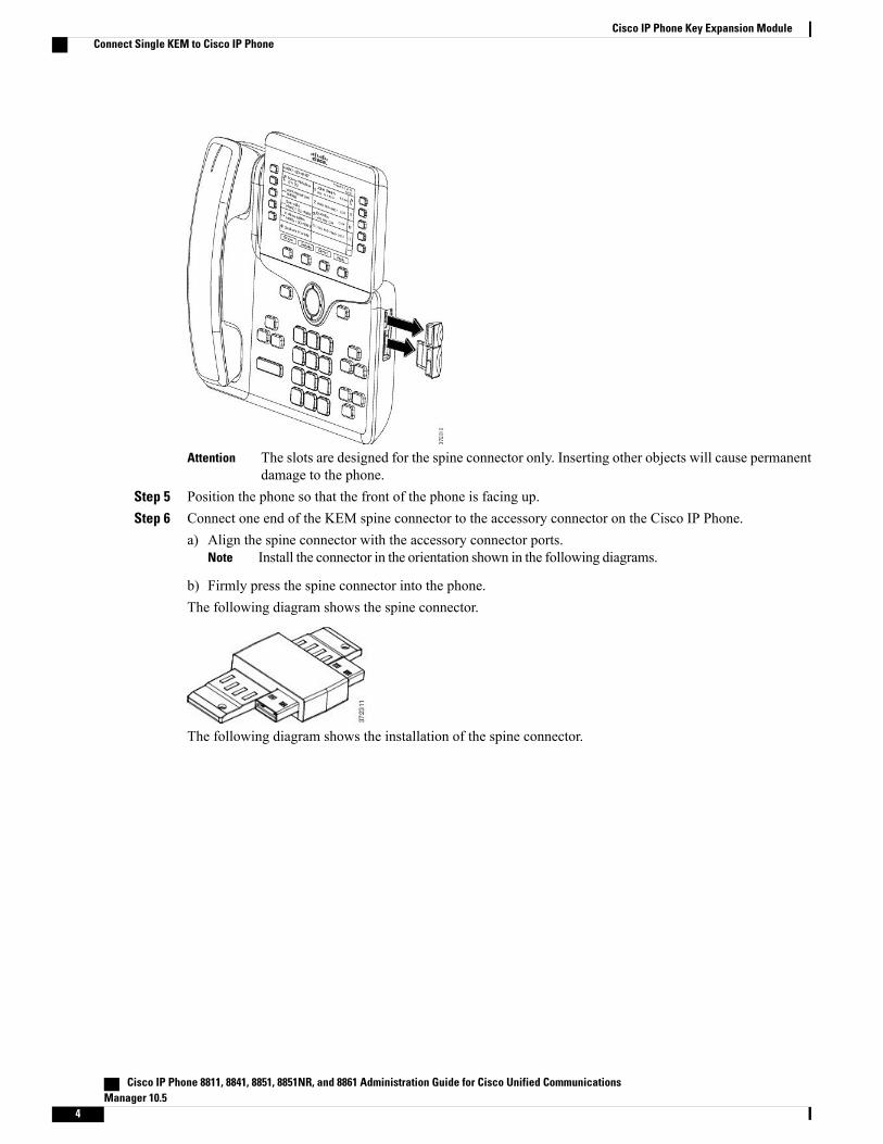
The slots are designed for the spine connector only. Inserting other objects will cause permanentdamage to the phone.
Attention
Step 5 Position the phone so that the front of the phone is facing up.Step 6 Connect one end of the KEM spine connector to the accessory connector on the Cisco IP Phone.
a) Align the spine connector with the accessory connector ports.Install the connector in the orientation shown in the following diagrams.Note
b) Firmly press the spine connector into the phone.The following diagram shows the spine connector.
The following diagram shows the installation of the spine connector.
Cisco IP Phone 8811, 8841, 8851, 8851NR, and 8861 Administration Guide for Cisco Unified CommunicationsManager 10.5
4
Cisco IP Phone Key Expansion ModuleConnect Single KEM to Cisco IP Phone

Step 7 Connect the other end of the spine connector to the KEM as shown in the following figure.a) Align the spine connector with the KEM accessory connector ports.b) Firmly press the KEM into the spine connector.
Cisco IP Phone 8811, 8841, 8851, 8851NR, and 8861 Administration Guide for Cisco Unified Communications Manager10.5
5
Cisco IP Phone Key Expansion ModuleConnect Single KEM to Cisco IP Phone
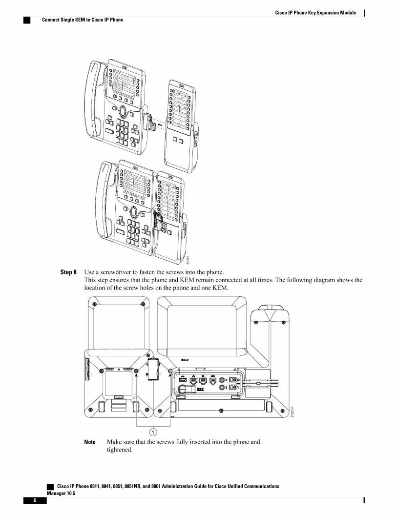
Step 8 Use a screwdriver to fasten the screws into the phone.This step ensures that the phone and KEM remain connected at all times. The following diagram shows thelocation of the screw holes on the phone and one KEM.
Make sure that the screws fully inserted into the phone andtightened.
Note
Cisco IP Phone 8811, 8841, 8851, 8851NR, and 8861 Administration Guide for Cisco Unified CommunicationsManager 10.5
6
Cisco IP Phone Key Expansion ModuleConnect Single KEM to Cisco IP Phone
Step 9 (Optional) Install the footstands on the phone and on the KEM, and adjust both footstands to rest evenly onthe work surface.
Step 10 Plug the Ethernet cable into the phone.
Connect Two or Three KEMs to Cisco IP PhoneProcedure
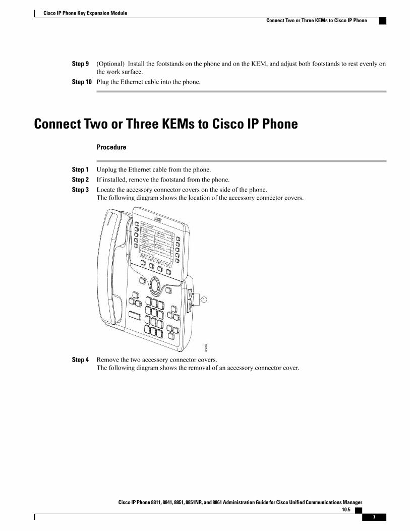
Step 1 Unplug the Ethernet cable from the phone.Step 2 If installed, remove the footstand from the phone.Step 3 Locate the accessory connector covers on the side of the phone.
The following diagram shows the location of the accessory connector covers.
Step 4 Remove the two accessory connector covers.The following diagram shows the removal of an accessory connector cover.
Cisco IP Phone 8811, 8841, 8851, 8851NR, and 8861 Administration Guide for Cisco Unified Communications Manager10.5
7
Cisco IP Phone Key Expansion ModuleConnect Two or Three KEMs to Cisco IP Phone
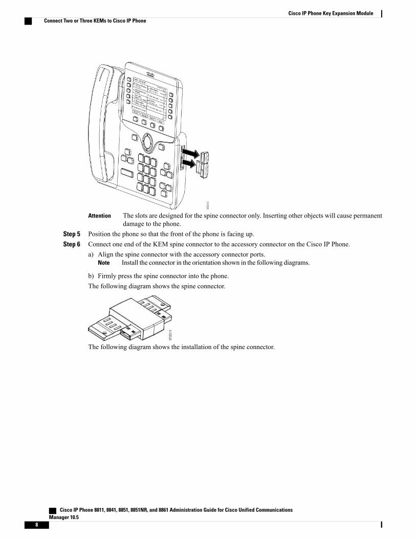
The slots are designed for the spine connector only. Inserting other objects will cause permanentdamage to the phone.
Attention
Step 5 Position the phone so that the front of the phone is facing up.Step 6 Connect one end of the KEM spine connector to the accessory connector on the Cisco IP Phone.
a) Align the spine connector with the accessory connector ports.Install the connector in the orientation shown in the following diagrams.Note
b) Firmly press the spine connector into the phone.The following diagram shows the spine connector.
The following diagram shows the installation of the spine connector.
Cisco IP Phone 8811, 8841, 8851, 8851NR, and 8861 Administration Guide for Cisco Unified CommunicationsManager 10.5
8
Cisco IP Phone Key Expansion ModuleConnect Two or Three KEMs to Cisco IP Phone
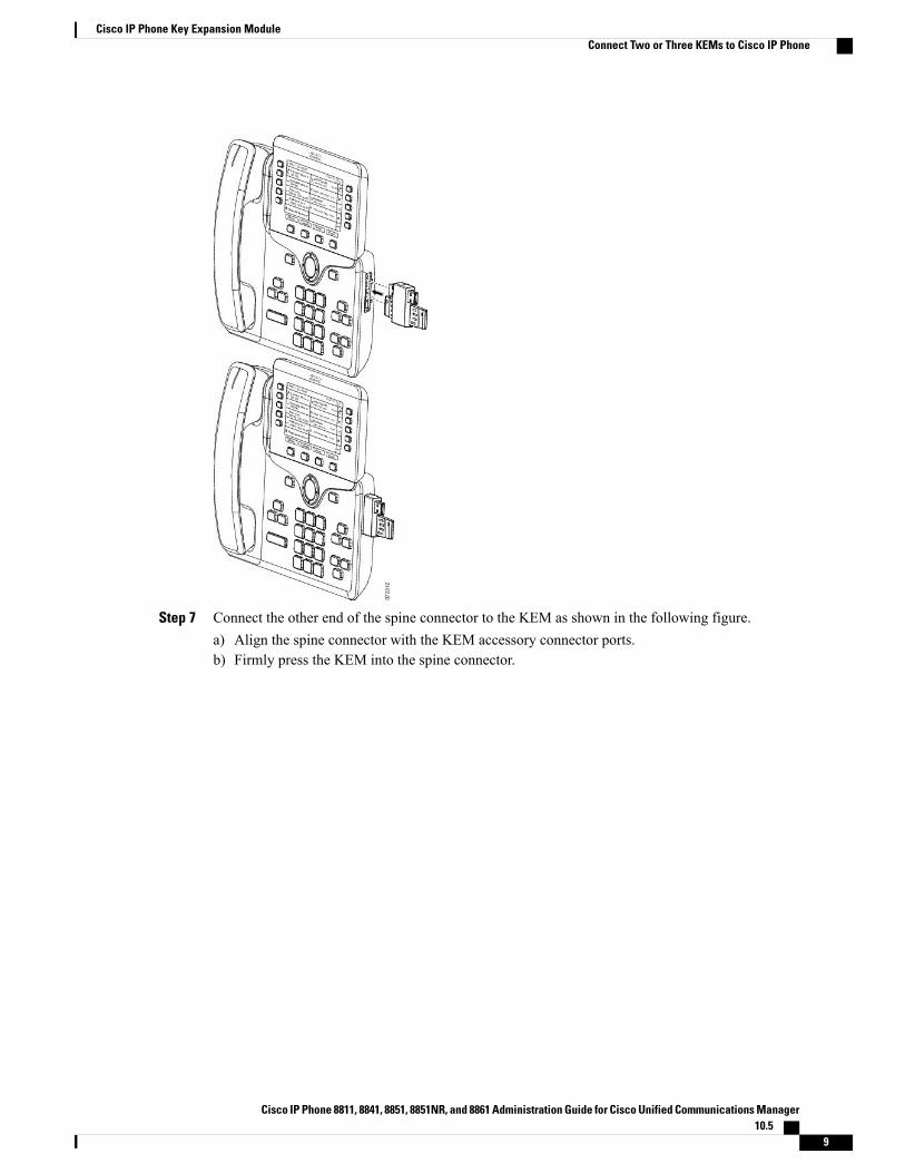
Step 7 Connect the other end of the spine connector to the KEM as shown in the following figure.a) Align the spine connector with the KEM accessory connector ports.b) Firmly press the KEM into the spine connector.
Cisco IP Phone 8811, 8841, 8851, 8851NR, and 8861 Administration Guide for Cisco Unified Communications Manager10.5
9
Cisco IP Phone Key Expansion ModuleConnect Two or Three KEMs to Cisco IP Phone
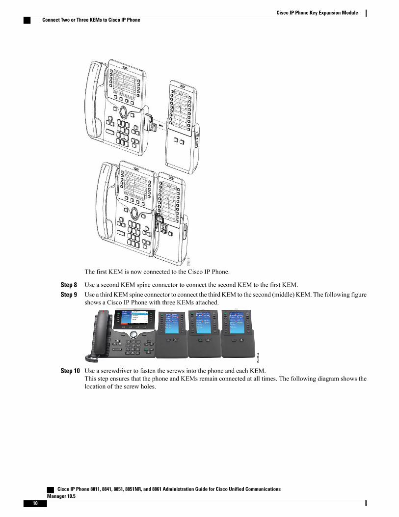
The first KEM is now connected to the Cisco IP Phone.
Step 8 Use a second KEM spine connector to connect the second KEM to the first KEM.Step 9 Use a third KEM spine connector to connect the third KEM to the second (middle) KEM. The following figure
shows a Cisco IP Phone with three KEMs attached.
Step 10 Use a screwdriver to fasten the screws into the phone and each KEM.This step ensures that the phone and KEMs remain connected at all times. The following diagram shows thelocation of the screw holes.
Cisco IP Phone 8811, 8841, 8851, 8851NR, and 8861 Administration Guide for Cisco Unified CommunicationsManager 10.5
10
Cisco IP Phone Key Expansion ModuleConnect Two or Three KEMs to Cisco IP Phone
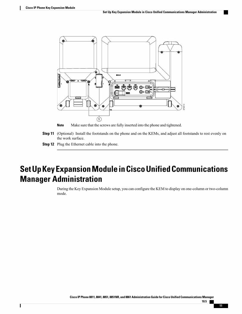
Make sure that the screws are fully inserted into the phone and tightened.Note
Step 11 (Optional) Install the footstands on the phone and on the KEMs, and adjust all footstands to rest evenly onthe work surface.
Step 12 Plug the Ethernet cable into the phone.
Set Up Key Expansion Module in Cisco Unified CommunicationsManager Administration
During the Key ExpansionModule setup, you can configure the KEM to display on one-column or two-columnmode.
Cisco IP Phone 8811, 8841, 8851, 8851NR, and 8861 Administration Guide for Cisco Unified Communications Manager10.5
11
Cisco IP Phone Key Expansion ModuleSet Up Key Expansion Module in Cisco Unified Communications Manager Administration
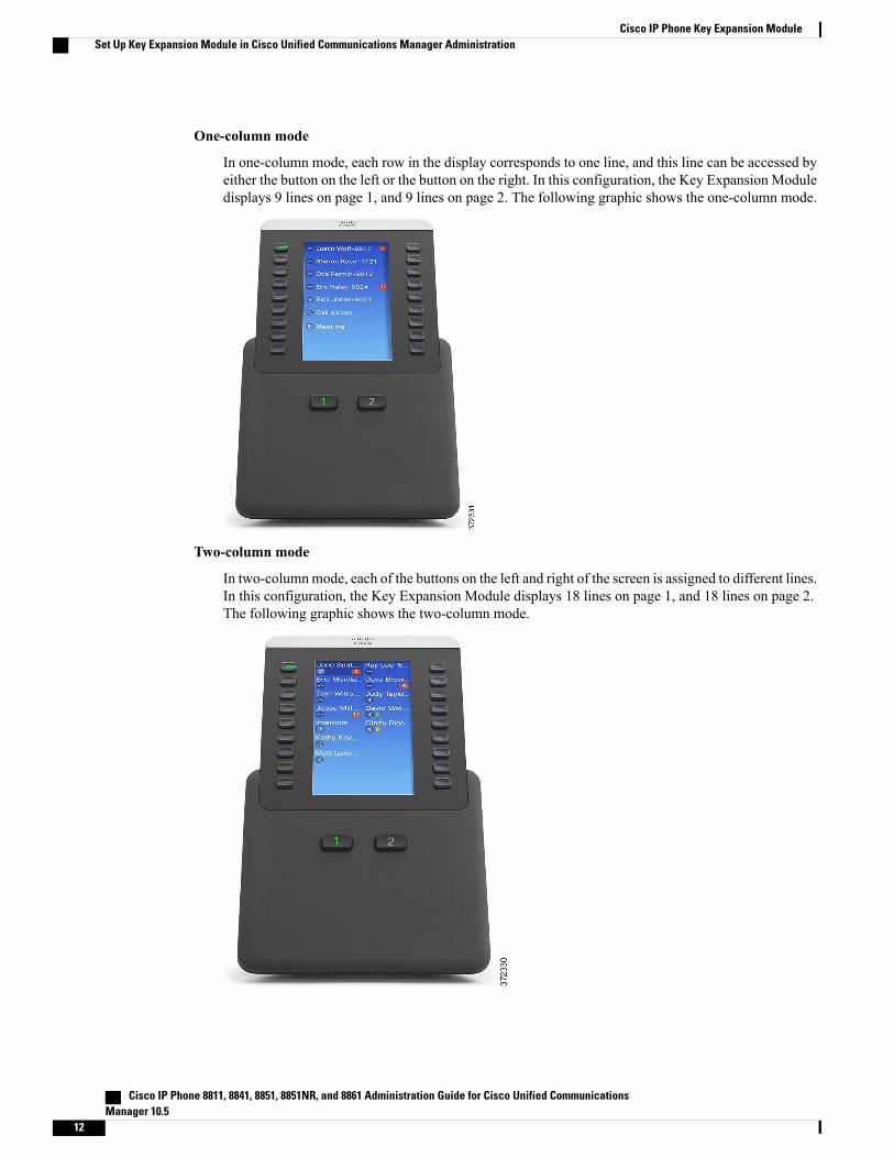
One-column mode
In one-column mode, each row in the display corresponds to one line, and this line can be accessed byeither the button on the left or the button on the right. In this configuration, the Key Expansion Moduledisplays 9 lines on page 1, and 9 lines on page 2. The following graphic shows the one-column mode.
Two-column mode
In two-columnmode, each of the buttons on the left and right of the screen is assigned to different lines.In this configuration, the Key Expansion Module displays 18 lines on page 1, and 18 lines on page 2.The following graphic shows the two-column mode.
Cisco IP Phone 8811, 8841, 8851, 8851NR, and 8861 Administration Guide for Cisco Unified CommunicationsManager 10.5
12
Cisco IP Phone Key Expansion ModuleSet Up Key Expansion Module in Cisco Unified Communications Manager Administration
If the label is longer than the display space in both one- and two-columnmode, the text contains an ellipsis(…) .
Note
Procedure
Step 1 In Cisco Unified Communications Manager Administration, choose Device > Phone.The Find and List Phones window appears. You can search for one or more phones that you want to configurefor the Cisco IP Phone 8800 Key Expansion Module.
Step 2 Select and enter your search criteria and click Find.The Find and List Phones window appears with a list of phones that match your search criteria.
Step 3 Click the phone that you want to configure for the Cisco IP Phone 8800 Key Expansion Module. The PhoneConfiguration window appears.
Step 4 Scroll down to the Expansion Module Information section on the right pane of the Phone Configurationwindow, and choose the appropriate expansion module (or “none”) for the Module 1, Module 2 and Module3 fields, in that order.For the number of supported KEMs per phone model, see Cisco IP Phone Key Expansion Module SetupOverview, on page 1.
Step 5 Be sure to select the phone button template (in the Device Information portion of the Phone Configurationwindow) that is configured to make full use of the KEMs attached to the phone.
Step 6 Depending on your requirements, enable the One Column Display for KEM field for one-column mode, ordisable the field for two-column mode.
Step 7 Click Save.
Access Key Expansion Module SetupAfter you install one or more KEMs on the phone and configure them in Cisco Unified CommunicationsManager Administration, the KEMs are automatically recognized by the phone.
When multiple KEMs are attached, they are numbered according to the order in which they connect to thephone:
• Key Expansion Module 1 is the KEM closest to the phone.
• Key Expansion Module 2 is the KEM in the middle.
• Key Expansion Module 3 is the KEM farthest to the right.
You can select a KEM, and then choose one of the following softkeys:
• Exit: Returns to the Applications menu.
• Details: Provides details about the selected KEM.
• Setup: Allows you to configure the brightness of the selected KEM. Setting the brightness can also bedone using the Preferences menu on the phone.
Cisco IP Phone 8811, 8841, 8851, 8851NR, and 8861 Administration Guide for Cisco Unified Communications Manager10.5
13
Cisco IP Phone Key Expansion ModuleAccess Key Expansion Module Setup
Procedure
Step 1 On the phone, press Applications .Step 2 Press Accessories.
All properly installed and configured KEMs display in the list of accessories.
Reset Key Expansion ModuleThis procedure gives the steps for the Key Expansion Module factory reset.
Procedure
Step 1 Power on the KEM, press Page 1, and do not release the key. When the LCD turns white, continue pressingPage 1 for at least one second.
Step 2 Release Page 1; LEDs should turn red. Immediately press Page 2 and continue pressing Page 2 for at leastone second.
Step 3 Release Page 2; all LEDs should turn amber.Step 4 Press Lines 5, 14, 1, 18, 10, and 9 in sequence.
The LCD should turn blue, and the spinning loader icon displays in the center.
The KEM resets.
Troubleshoot the Key Expansion ModuleTo obtain Key Expansion Module (KEM) troubleshooting information, follow these steps:
Procedure
Step 1 Open a CLI.Step 2 Enter the following command to enter debug mode:
debugsh
Step 3 Enter ? to see all available commands and options.Step 4 Use the applicable commands and options to find the desired KEM information.Step 5 To exit debug mode, press Ctrl-C.
Cisco IP Phone 8811, 8841, 8851, 8851NR, and 8861 Administration Guide for Cisco Unified CommunicationsManager 10.5
14
Cisco IP Phone Key Expansion ModuleReset Key Expansion Module


![Photoshop Step 4 [OPTIONAL]trantor.sheridanc.on.ca/student/...marshabitat.pdf · Step 4 [OPTIONAL]: Photoshop 1. Personal Living Spaces 2. Central Core 3. Elevator 4. Kitchen/Social](https://static.fdocuments.in/doc/165x107/5f39eeac5bf22a6b6548d0d5/photoshop-step-4-optional-step-4-optional-photoshop-1-personal-living-spaces.jpg)


![[Step-by-Step] Cisco Unity Connection SCCP …Step-by-Step] Cisco Unity Connection SCCP Integration with CUCM Cisco Call Manager The optional Cisco Unity Connection server, available](https://static.fdocuments.in/doc/165x107/5ae0402c7f8b9a1c248cf868/step-by-step-cisco-unity-connection-sccp-step-by-step-cisco-unity-connection.jpg)
![Light Account Process Step by step Guide · 4. [Optional] Supplier may confirm receipt of the PO (Order confirmation) through Light Account 5. [Optional] Supplier may submit the ship](https://static.fdocuments.in/doc/165x107/5f82225fa9b5dd09d876a559/light-account-process-step-by-step-guide-4-optional-supplier-may-confirm-receipt.jpg)

![Legend Global = Subgraph call Make Data Dir = Step Load Genomic Sequence & Annotation = Subgraph reference Proteome Analysis = Optional step [Taxon] Pk.](https://static.fdocuments.in/doc/165x107/56649f4d5503460f94c6d2a2/legend-global-subgraph-call-make-data-dir-step-load-genomic-sequence-.jpg)


