Cisco CCENT/CCNA ICND1 100-101: Official Cert …...4 Cisco CCENT/CCNA ICND1 100-101 Official Cert...
40
Getting Started You just got this book. You have probably already read (or quickly skimmed) the Introduction. And you are wondering, is this where I really start reading, or can I skip ahead to Chapter 1? Stop to read this “Getting Started” section to think about how you will study for this exam. Your study will go much better if you take time (maybe 15 minutes) to think about a few key points about how to study, before starting on this journey that will take you many hours, over many weeks. That’s what this “Getting Started” section will help you do. A Brief Perspective on Cisco Certification Exams Cisco sets the bar pretty high for passing the ICND1, ICND2, and/or CCNA exams. Most anyone can study and pass these exams, but it takes more than just a quick read through the book and the cash to pay for the exam. The challenge of these exams comes from many angles. Each of these exams covers a lot of concepts, as well as many commands specific to Cisco devices. Beyond knowledge, these Cisco exams also require deep skills. You must be able to analyze and predict what really happens in a network. You must be able to configure Cisco devices to work correctly in those networks. And you must be ready to troubleshoot problems when the network does not work correctly. The more challenging questions on these exams work a lot like a jigsaw puzzle—but with four out of every five puzzle pieces not even in the room. To solve the puzzle, you have to mentally re-create the missing pieces. To do that, you must know each networking concept and remember how the concepts work together. You also have to match the concepts with what happens on the devices with the configuration commands that tell the devices what to do. You also have to connect the concepts, and the configuration, with the meaning of the output of various troubleshooting commands, to analyze how the network is working and why it is not working right now. For example, you need to know IP subnetting well, and that topic includes some math. A simple question—one that might be too simple to be a real exam question—would tell you enough of the numbers so that all you have to do is the equivalent of a little addition or multiplication to find a number called a subnet ID. A more exam-realistic question makes you connect concepts together to set up the math problem. For example, a question might give you a network diagram and ask you to list the subnet ID used in one part of the diagram. But the diagram has no numbers at all. Instead, you have the output of a command from a router, for example, the show ip ospf database command, which does list some numbers. But before you can use those numbers, you might need to predict how the devices are configured and what other troubleshooting commands
Transcript of Cisco CCENT/CCNA ICND1 100-101: Official Cert …...4 Cisco CCENT/CCNA ICND1 100-101 Official Cert...
Getting StartedYou just got this book. You have probably already read (or quickly skimmed) the Introduction. And you are wondering, is this where I really start reading, or can I skip ahead to Chapter 1?
Stop to read this “Getting Started” section to think about how you will study for this exam. Your study will go much better if you take time (maybe 15 minutes) to think about a few key points about how to study, before starting on this journey that will take you many hours, over many weeks. That’s what this “Getting Started” section will help you do.
A Brief Perspective on Cisco Certification ExamsCisco sets the bar pretty high for passing the ICND1, ICND2, and/or CCNA exams. Most anyone can study and pass these exams, but it takes more than just a quick read through the book and the cash to pay for the exam.
The challenge of these exams comes from many angles. Each of these exams covers a lot of concepts, as well as many commands specific to Cisco devices. Beyond knowledge, these Cisco exams also require deep skills. You must be able to analyze and predict what really happens in a network. You must be able to configure Cisco devices to work correctly in those networks. And you must be ready to troubleshoot problems when the network does not work correctly.
The more challenging questions on these exams work a lot like a jigsaw puzzle—but with four out of every five puzzle pieces not even in the room. To solve the puzzle, you have to mentally re-create the missing pieces. To do that, you must know each networking concept and remember how the concepts work together. You also have to match the concepts with what happens on the devices with the configuration commands that tell the devices what to do. You also have to connect the concepts, and the configuration, with the meaning of the output of various troubleshooting commands, to analyze how the network is working and why it is not working right now.
For example, you need to know IP subnetting well, and that topic includes some math. A simple question—one that might be too simple to be a real exam question—would tell you enough of the numbers so that all you have to do is the equivalent of a little addition or multiplication to find a number called a subnet ID.
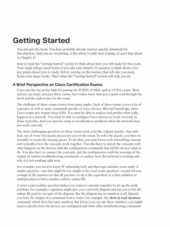
A more exam-realistic question makes you connect concepts together to set up the math problem. For example, a question might give you a network diagram and ask you to list the subnet ID used in one part of the diagram. But the diagram has no numbers at all. Instead, you have the output of a command from a router, for example, the show ip ospf database command, which does list some numbers. But before you can use those numbers, you might need to predict how the devices are configured and what other troubleshooting commands
4 Cisco CCENT/CCNA ICND1 100-101 Official Cert Guide
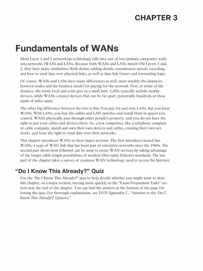
would tell you. So you end up with a question like a puzzle, as shown in Figure 1. The ques-tion puts some pieces in the right place; you have to find other pieces using different com-mands and by applying your knowledge. And some pieces will just remain unknown for a given question.
Predict Configuration:OSPF on Routers
Given: Output ofshow ip ospf database
Given:Router Topology Drawing
Calculate:IP subnet IDs
Predict Output:show ip route
Predict Output:show ip Interface brief
Figure 1 Filling in Puzzle Pieces with Your Analysis Skills
These skills require that you prepare by doing more than just reading and memorizing what you read. Of course, you will need to read many pages in this book to learn many indi-vidual facts and how these facts are related to each other. But a big part of this book lists exercises beyond reading, exercises that help you build the skills to solve these networking puzzles.
Suggestions for How to Approach Your Study with This BookWhile these exams are challenging, many people pass them every day. So, what do you need to do to be ready to pass, beyond reading and remembering all the facts? You need to devel-op skills. You need to mentally link each idea with other related ideas. Doing that requires additional work. To help you along the way, the next few pages give you five key perspec-tives about how to use this book to build those skills and make those connections, before you dive into this exciting but challenging world of learning networking on Cisco gear.
Not One Book: 29 Short Read-and-Review Sessions
First, look at your study as a series of read-and-review tasks, each on a relatively small set of related topics.
Each of the core chapters of this book (1 through 29) have around 22 pages of content on average. If you glance around any of those chapters, you will find a heading called “Foundation Topics” on about the fifth page of each chapter. From there to the “Exam Preparation Tasks” section at the end of the chapter, the chapters average about 22 pages.
Getting Started 5
So, do not approach this book as one big book. Treat the task of your first read of a chapter as a separate task. Anyone can read 22 pages. Having a tough day? Each chapter has two or three major sections, so read just one of them. Or, do some related labs or review something you have already read. This book organizes the content into topics of a more manageable size to give you something more digestible to manage your study time throughout the book.
For Each Chapter, Do Not Neglect Practice
Next, plan to use the practice tasks at the end of each chapter.
Each chapter ends with practice and study tasks under a heading “Exam Preparation Tasks.” Doing these tasks, and doing them at the end of the chapter, really does help you get ready. Do not put off using these tasks until later! The chapter-ending “Exam Preparation Tasks” section helps you with the first phase of deepening your knowledge and skills of the key topics, remembering terms and linking the concepts together in your brain so that you can remember how it all fits together.
The following list describes the majority of the activities you will find in “Exam Preparation Tasks” sections:
■ Review key topics
■ Complete memory tables
■ Define key terms
■ Review command summary tables
■ Review feature configuration checklists
■ Do subnetting exercises
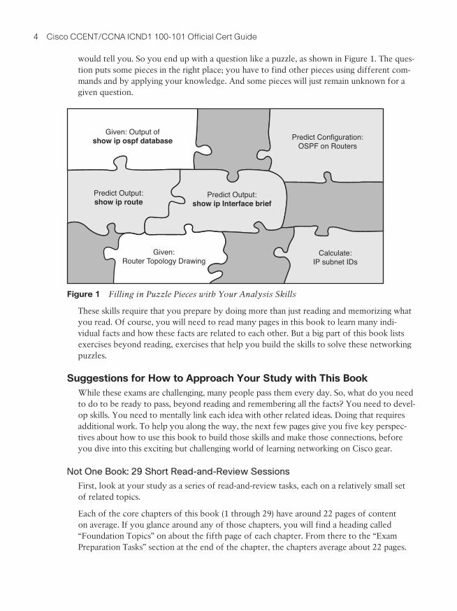
Approach each chapter with the same plan. You can choose to read the entire core (Foundation Topics) section of each chapter, or you can choose to skim some chapters, based on your score on the “Do I Know This Already?” (DIKTA) quiz, a pre-chapter self-assessment quiz at the beginning of most chapters. However, regardless of whether you skim or read thoroughly, do the study tasks in the “Exam Preparation Tasks” section at the end of the chapter. Figure 2 shows the overall flow.
TakeDIKTAQuiz
DoExam Prep
Tasks
High Score (Skim) Foundation Topics
Low Score (Read) Foundation Topics
Figure 2 Suggested Approach to Each Chapter
Use Book Parts for Major Milestones
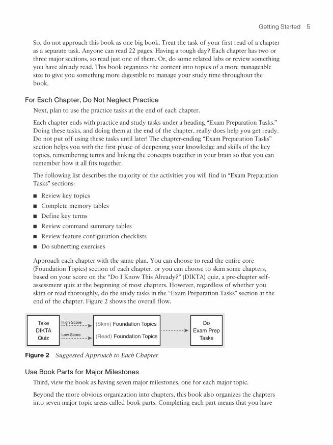
Third, view the book as having seven major milestones, one for each major topic.
Beyond the more obvious organization into chapters, this book also organizes the chapters into seven major topic areas called book parts. Completing each part means that you have
6 Cisco CCENT/CCNA ICND1 100-101 Official Cert Guide
completed a major area of study. At the end of each part, take a little extra time. Do the Part Review tasks at the end of each part. Ask yourself where you are weak and where you are strong. And give yourself some reward for making it to a major milestone. Figure 3 lists the seven parts in this book.
Networking Fundamentals
Seven Major Milestones: Book Parts
Part Prep Tasks
Ethernet LANs and Switches Part Prep Tasks
IP Version 4 Addressing and Subnetting Part Prep Tasks
Implementing IP Version 4 Part Prep Tasks
Advanced IPv4 Addressing Concepts Part Prep Tasks
IPv4 Services Part Prep Tasks
IP Version 6 Part Prep Tasks
Figure 3 Parts as Major Milestones
The tasks in the Part Review sections focus on helping you apply concepts (from that book part) to new scenarios for the exam. Some tasks use sample test questions so that you can think through and analyze a problem. This process helps you refine what you know and to realize what you did not quite yet understand. Some tasks use mind map exercises that help you mentally connect the theoretical concepts with the configuration and verification com-mands. These Part Review activities help build these skills.
Note that the part review directs you to use the Pearson Certification Practice Test (PCPT) software to access the practice questions. Each part review tells you to repeat the DIKTA questions, but using the PCPT software. Each part review also directs you how to access a specific set of questions reserved for reviewing concepts at part review. Note that the PCPT software and exam databases with this book give you the rights to additional questions as well; Chapter 30, “Final Review,” gives some recommendations on how to best use those questions for your final exam preparation.
Also, consider setting a goal date for finishing each part of the book, and a reward as well! Plan a break, some family time, some time out exercising, eating some good food—what-ever helps you get refreshed and motivated for the next part.
Use the Final Review Chapter to Refine Skills
Fourth, do the tasks outlined in the final preparation chapter (Chapter 30) at the end of this book.
The Final Review chapter has two major goals. First, it helps you further develop the analy-sis skills you need to answer the more complicated questions on the exam. Many questions require that you connect ideas about concepts, configuration, verification, and trouble-shooting. More reading on your part does not develop all these skills; this chapter’s tasks give you activities to further develop these skills.
Getting Started 7
The tasks in the Final Review chapter also help you find your weak areas. This final ele-ment gives you repetition with high-challenge exam questions, uncovering any gaps in your knowledge. Many of the questions are purposefully designed to test your knowledge of the most common mistakes and misconceptions, helping you avoid some of the common pit-falls people experience with the actual exam.
Set Goals and Track Your Progress
Finally, before you start reading the book and doing the rest of these study tasks, take the time to make a plan, set some goals, and be ready to track your progress.
While making lists of tasks might or might not appeal to you, depending on your personal-ity, goal setting can help everyone studying for these exams. And to do the goal setting, you need to know what tasks you plan to do.
As for the list of tasks to do when studying, you do not have to use a detailed task list. (You could list every single task in every chapter-ending “Exam Preparation Tasks” section, every task in the Part Review tasks section, and every task in the Final Preparation Tasks chapter.) However, listing the major tasks can be enough.
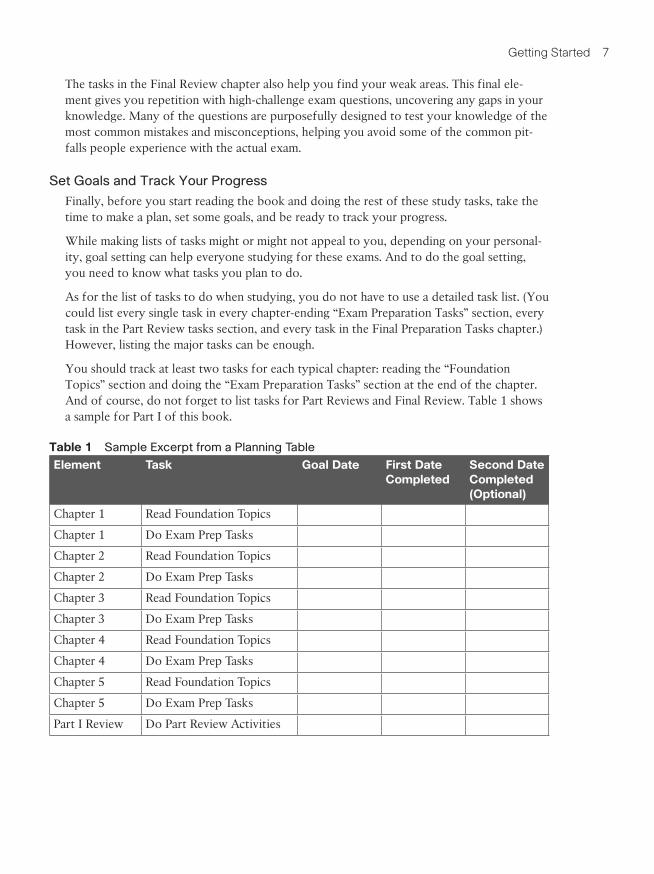
You should track at least two tasks for each typical chapter: reading the “Foundation Topics” section and doing the “Exam Preparation Tasks” section at the end of the chapter. And of course, do not forget to list tasks for Part Reviews and Final Review. Table 1 shows a sample for Part I of this book.
Table 1 Sample Excerpt from a Planning Table
Element Task Goal Date First Date Completed
Second Date Completed (Optional)
Chapter 1 Read Foundation Topics
Chapter 1 Do Exam Prep Tasks
Chapter 2 Read Foundation Topics
Chapter 2 Do Exam Prep Tasks
Chapter 3 Read Foundation Topics
Chapter 3 Do Exam Prep Tasks
Chapter 4 Read Foundation Topics
Chapter 4 Do Exam Prep Tasks
Chapter 5 Read Foundation Topics
Chapter 5 Do Exam Prep Tasks
Part I Review Do Part Review Activities
8 Cisco CCENT/CCNA ICND1 100-101 Official Cert Guide
NOTE Appendix P, “Study Planner,” on the DVD that comes with this book, contains a complete planning checklist like Table 1 for the tasks in this book. This spreadsheet allows you to update and save the file to note your goal dates and the tasks you have completed.
Use your goal dates as a way to manage your study, and not as a way to get discouraged if you miss a date. Pick reasonable dates that you can meet. When setting your goals, think about how fast you read and the length of each chapter’s “Foundation Topics” section, as listed in the Table of Contents. Then, when you finish a task sooner than planned, move up the next few goal dates.
If you miss a few dates, do not start skipping the tasks listed at the ends of the chapters! Instead, think about what is impacting your schedule—real life, commitments, and so on—and either adjust your goals or work a little harder on your study.
Two Options When Studying for the 200-120 CCNA ExamTo get a CCNA certification, you choose either a one-exam or two-exam path.
When using the two-exam path, use each book separately, and take the matching Cisco exam. In other words, use the Cisco CCENT/CCNA ICND1 100-101 Official Cert Guide, then pass the 100-101 ICND1 exam, and then do the same with the Cisco CCNA Routing and Switching ICND2 200-101 Official Cert Guide and the 200-101 ICND2 exam.
The one-exam path gives you a couple of study options. The 200-120 CCNA exam covers the topics in the combined ICND1 and ICND2 books. The only question is when to read each part of the two books. Two reasonable options exist when going with the one-exam option:
■ Complete all the ICND1 book, and then move on to the ICND2 book.
■ Move back and forth between the ICND1 and ICND2 books, by part, based on topics.
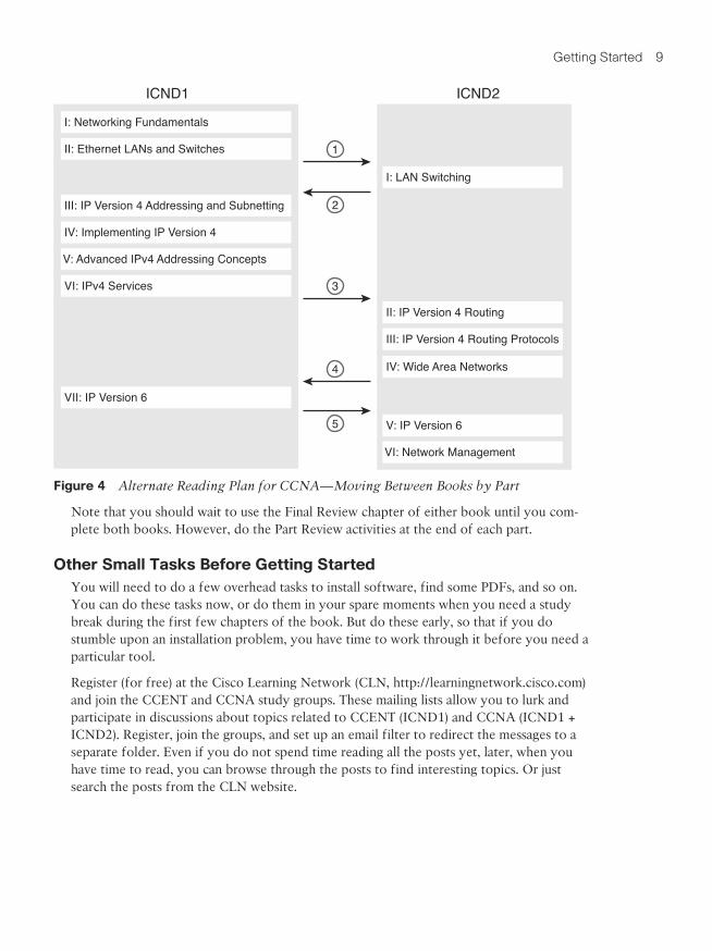
While the first option is pretty obvious, the second one is less obvious. So, Figure 4 shows a study plan when using the one-exam option, and you want to move back and forth between the two books. Why move back and forth? To read about similar topics all at once, as shown in Figure 4.
Getting Started 9
ICND1 ICND2
III: IP Version 4 Addressing and Subnetting
IV: Implementing IP Version 4
V: Advanced IPv4 Addressing Concepts
VI: IPv4 Services
I: Networking Fundamentals
II: Ethernet LANs and Switches
VII: IP Version 6
IV: Wide Area Networks
V: IP Version 6
VI: Network Management
II: IP Version 4 Routing
III: IP Version 4 Routing Protocols
I: LAN Switching
1
2
3
4
5
Figure 4 Alternate Reading Plan for CCNA—Moving Between Books by Part
Note that you should wait to use the Final Review chapter of either book until you com-plete both books. However, do the Part Review activities at the end of each part.
Other Small Tasks Before Getting StartedYou will need to do a few overhead tasks to install software, find some PDFs, and so on. You can do these tasks now, or do them in your spare moments when you need a study break during the first few chapters of the book. But do these early, so that if you do stumble upon an installation problem, you have time to work through it before you need a particular tool.
Register (for free) at the Cisco Learning Network (CLN, http://learningnetwork.cisco.com) and join the CCENT and CCNA study groups. These mailing lists allow you to lurk and participate in discussions about topics related to CCENT (ICND1) and CCNA (ICND1 + ICND2). Register, join the groups, and set up an email filter to redirect the messages to a separate folder. Even if you do not spend time reading all the posts yet, later, when you have time to read, you can browse through the posts to find interesting topics. Or just search the posts from the CLN website.

10 Cisco CCENT/CCNA ICND1 100-101 Official Cert Guide
Find and print a copy of Appendix M, “Memory Tables.” Many of the Chapter Review sections use this tool, in which you take the incomplete tables from the appendix and com-plete the table to help you remember some key facts.
If you bought an eBook version of this book, find and download the media files (videos and Sim Lite software) per the instructions supplied on the last page of the eBook file under the heading “Where Are the Companion Files?”
Install the PCPT exam software and activate the exams. For more details on how to load the software, refer to the Introduction, under the heading “Install the Pearson Certification Practice Test Engine and Questions.”
Finally, install the Sim Lite software (unless you bought the full simulator product already). The Sim Lite that comes with this book contains a subset of the lab exercises in the full Pearson Network Simulator product.
Getting Started—NowNow dive in to your first of many short, manageable tasks: reading Chapter 1, “The TCP/IP and OSI Networking Models.” Enjoy!

This page intentionally left blank
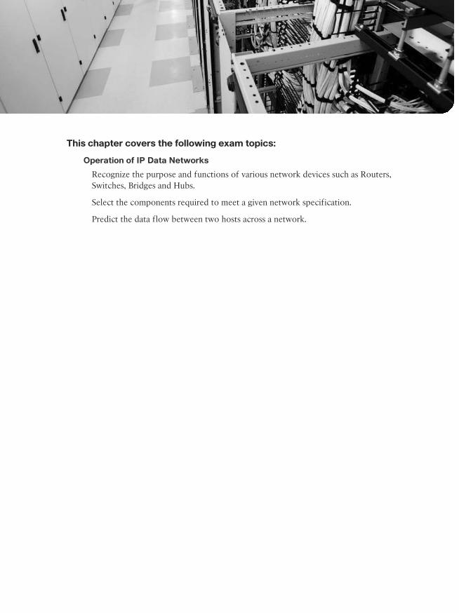
This chapter covers the following exam topics:
Operation of IP Data Networks
Recognize the purpose and functions of various network devices such as Routers, Switches, Bridges and Hubs.
Select the components required to meet a given network specification.
Predict the data flow between two hosts across a network.
CHAPTER 3
Fundamentals of WANsMost Layer 1 and 2 networking technology falls into one of two primary categories: wide-area networks (WAN) and LANs. Because both WANs and LANs match OSI Layers 1 and 2, they have many similarities: Both define cabling details, transmission speeds, encoding, and how to send data over physical links, as well as data link frames and forwarding logic.
Of course, WANs and LANs have many differences as well, most notably the distances between nodes and the business model for paying for the network. First, in terms of the distance, the terms local and wide give us a small hint: LANs typically include nearby devices, while WANs connect devices that can be far apart, potentially hundreds or thou-sands of miles apart.
The other big difference between the two is this: You pay for and own LANs, but you lease WANs. With LANs, you buy the cables and LAN switches and install them in spaces you control. WANs physically pass through other people’s property, and you do not have the right to put your cables and devices there. So, a few companies, like a telephone company or cable company, install and own their own devices and cables, creating their own net-works, and lease the right to send data over their networks.
This chapter introduces WANs in three major sections. The first introduces leased line WANs, a type of WAN link that has been part of enterprise networks since the 1960s. The second part shows how Ethernet can be used to create WAN services by taking advantage of the longer cable length possibilities of modern fiber-optic Ethernet standards. The last part of the chapter takes a survey of common WAN technology used to access the Internet.
“Do I Know This Already?” QuizUse the “Do I Know This Already?” quiz to help decide whether you might want to skim this chapter, or a major section, moving more quickly to the “Exam Preparation Tasks” sec-tion near the end of the chapter. You can find the answers at the bottom of the page fol-lowing the quiz. For thorough explanations, see DVD Appendix C, “Answers to the ‘Do I Know This Already?’ Quizzes.”
68 Cisco CCENT/CCNA ICND1 100-101 Official Cert Guide
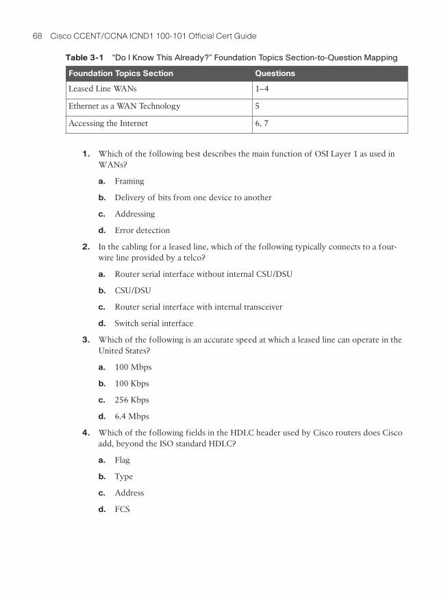
Table 3-1 “Do I Know This Already?” Foundation Topics Section-to-Question Mapping
Foundation Topics Section Questions
Leased Line WANs 1–4
Ethernet as a WAN Technology 5
Accessing the Internet 6, 7
1. Which of the following best describes the main function of OSI Layer 1 as used in WANs?
a. Framing
b. Delivery of bits from one device to another
c. Addressing
d. Error detection
2. In the cabling for a leased line, which of the following typically connects to a four-wire line provided by a telco?
a. Router serial interface without internal CSU/DSU
b. CSU/DSU
c. Router serial interface with internal transceiver
d. Switch serial interface
3. Which of the following is an accurate speed at which a leased line can operate in the United States?
a. 100 Mbps
b. 100 Kbps
c. 256 Kbps
d. 6.4 Mbps
4. Which of the following fields in the HDLC header used by Cisco routers does Cisco add, beyond the ISO standard HDLC?
a. Flag
b. Type
c. Address
d. FCS
3
Chapter 3: Fundamentals of WANs 69
5. Two routers, R1 and R2, connect using an Ethernet over MPLS service. The service provides point-to-point service between these two routers only, as a Layer 2 Ethernet service. Which of the following are the most likely to be true about this WAN? (Choose two answers.)
a. R1 will connect to a physical Ethernet link, with the other end of the cable connected to R2.
b. R1 will connect to a physical Ethernet link, with the other end of the cable connected to a device at the WAN service provider point of presence.
c. R1 will forward data link frames to R2 using an HDLC header/trailer.
d. R1 will forward data link frames to R2 using an Ethernet header/trailer.
6. Which of the following Internet access technologies, used to connect a site to an ISP, offers asymmetric speeds? (Choose two answers.)
a. Leased lines
b. DSL
c. Cable Internet
d. BGP
7. Fred has just added DSL service at his home, with a separate DSL modem and con-sumer-grade router with four Ethernet ports. Fred wants to use the same old phone he was using before the installation of DSL. Which is most likely true about the phone cabling and phone used with his new DSL installation?
a. He uses the old phone, cabled to one of the router/switch device’s Ethernet ports.
b. He uses the old phone, cabled to the DSL modem’s ports.
c. He uses the old phone, cabled to an existing telephone port, and not to any new device.
d. The old phone must be replaced with a digital phone.
70 Cisco CCENT/CCNA ICND1 100-101 Official Cert Guide
Foundation Topics
Leased Line WANsImagine that you are the primary network engineer for an enterprise TCP/IP internetwork. Your company is building a new building at a site 100 miles away from your corporate head-quarters. You will of course install a LAN throughout the new building, but you also need to connect that new remote LAN to the rest of the existing enterprise TCP/IP network.
To connect the new building’s LAN to the rest of the existing corporate network, you need some kind of a WAN. At a minimum, that WAN needs to be able to send data from the remote LAN back to the rest of the existing network and vice versa. Leased line WANs do exactly that, forwarding data between two routers.
From a basic point of view, a leased line WAN works a lot like an Ethernet crossover cable connecting two routers, but with few distance limitations. Each router can send at any time (full-duplex) over the leased line, for tens, hundreds, or even thousands of miles.
This section begins by giving some perspective about where leased lines fit with LANs and routers, because one main goal for a WAN is to move data between LANs. The rest of this first section explains the physical details about leased lines, followed with information about data link protocols.
Positioning Leased Lines with LANs and RoutersThe vast majority of end-user devices in an enterprise or SOHO network connect directly into a LAN. Many PCs use an Ethernet NIC that connects to a switch. More and more, devices use 802.11 wireless LANs, with some devices like phones and tablets supporting only wireless LAN connections.
Now think about a typical company that has many different locations. From a human resources perspective, it might have lots of employees that work at many locations. From a facilities perspective, the company might have a few large sites, with hundreds or even thousands of individual branch offices, stores, or other small locations. However, from a networking perspective, think of each site as being one or more LANs that need to com-municate with each other, and to communicate, those LANs need to be connected to each other using a WAN.
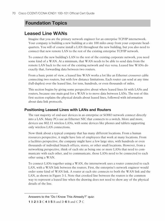
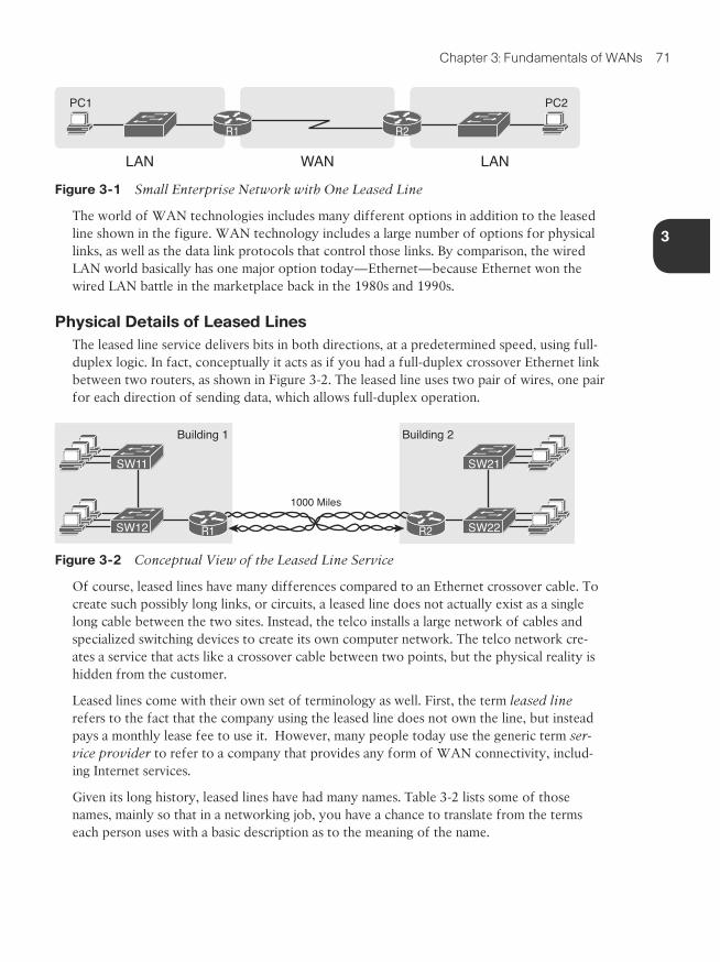
To connect LANs together using a WAN, the internetwork uses a router connected to each LAN, with a WAN link between the routers. First, the enterprise’s network engineer would order some kind of WAN link. A router at each site connects to both the WAN link and the LAN, as shown in Figure 3-1. Note that crooked line between the routers is the common way to represent a leased line when the drawing does not need to show any of the physical details of the line.
Answers to the “Do I Know This Already?” quiz:
1 B 2 B 3 C 4 B 5 B and D 6 B and C 7 C
3
Chapter 3: Fundamentals of WANs 71
PC1
LAN WAN LAN
PC2
R1 R2
Figure 3-1 Small Enterprise Network with One Leased Line
The world of WAN technologies includes many different options in addition to the leased line shown in the figure. WAN technology includes a large number of options for physical links, as well as the data link protocols that control those links. By comparison, the wired LAN world basically has one major option today—Ethernet—because Ethernet won the wired LAN battle in the marketplace back in the 1980s and 1990s.
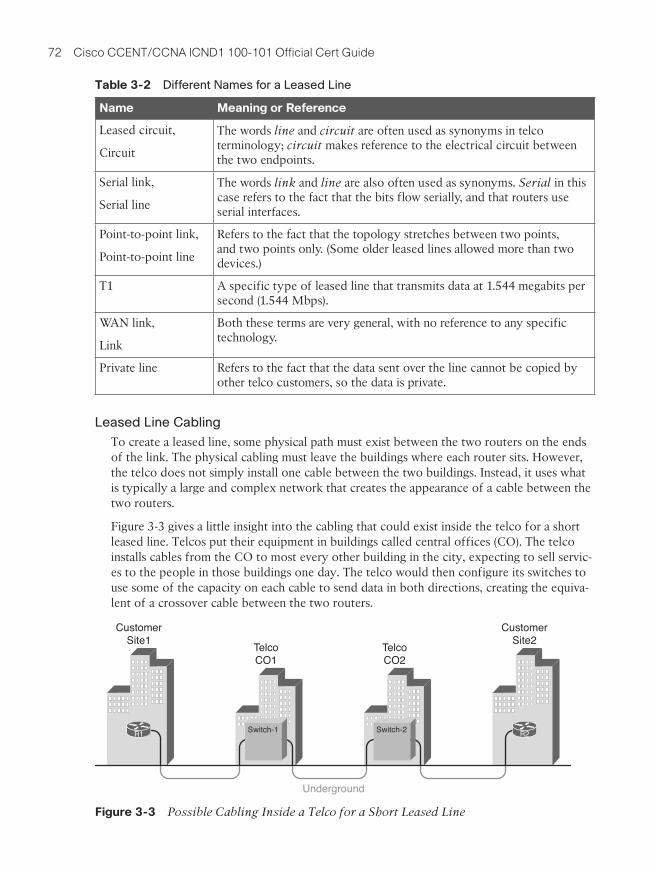
Physical Details of Leased LinesThe leased line service delivers bits in both directions, at a predetermined speed, using full-duplex logic. In fact, conceptually it acts as if you had a full-duplex crossover Ethernet link between two routers, as shown in Figure 3-2. The leased line uses two pair of wires, one pair for each direction of sending data, which allows full-duplex operation.
Building 1
1000 Miles
Building 2
R2R1
SW11
SW12
SW21
SW22
Figure 3-2 Conceptual View of the Leased Line Service
Of course, leased lines have many differences compared to an Ethernet crossover cable. To create such possibly long links, or circuits, a leased line does not actually exist as a single long cable between the two sites. Instead, the telco installs a large network of cables and specialized switching devices to create its own computer network. The telco network cre-ates a service that acts like a crossover cable between two points, but the physical reality is hidden from the customer.
Leased lines come with their own set of terminology as well. First, the term leased line refers to the fact that the company using the leased line does not own the line, but instead pays a monthly lease fee to use it. However, many people today use the generic term ser-vice provider to refer to a company that provides any form of WAN connectivity, includ-ing Internet services.
Given its long history, leased lines have had many names. Table 3-2 lists some of those names, mainly so that in a networking job, you have a chance to translate from the terms each person uses with a basic description as to the meaning of the name.
72 Cisco CCENT/CCNA ICND1 100-101 Official Cert Guide
Table 3-2 Different Names for a Leased Line
Name Meaning or Reference
Leased circuit,
Circuit
The words line and circuit are often used as synonyms in telco terminology; circuit makes reference to the electrical circuit between the two endpoints.
Serial link,
Serial line
The words link and line are also often used as synonyms. Serial in this case refers to the fact that the bits flow serially, and that routers use serial interfaces.
Point-to-point link,
Point-to-point line
Refers to the fact that the topology stretches between two points, and two points only. (Some older leased lines allowed more than two devices.)
T1 A specific type of leased line that transmits data at 1.544 megabits per second (1.544 Mbps).
WAN link,
Link
Both these terms are very general, with no reference to any specific technology.
Private line Refers to the fact that the data sent over the line cannot be copied by other telco customers, so the data is private.
Leased Line Cabling
To create a leased line, some physical path must exist between the two routers on the ends of the link. The physical cabling must leave the buildings where each router sits. However, the telco does not simply install one cable between the two buildings. Instead, it uses what is typically a large and complex network that creates the appearance of a cable between the two routers.
Figure 3-3 gives a little insight into the cabling that could exist inside the telco for a short leased line. Telcos put their equipment in buildings called central offices (CO). The telco installs cables from the CO to most every other building in the city, expecting to sell servic-es to the people in those buildings one day. The telco would then configure its switches to use some of the capacity on each cable to send data in both directions, creating the equiva-lent of a crossover cable between the two routers.
CustomerSite1
Underground
TelcoCO1
TelcoCO2
CustomerSite2
Switch-1 Switch-2R1 R2
Figure 3-3 Possible Cabling Inside a Telco for a Short Leased Line
3
Chapter 3: Fundamentals of WANs 73
Although what happens inside the telco is completely hidden from the telco customer, enterprise engineers do need to know about the parts of the link that exist inside the cus-tomer’s building at the router.
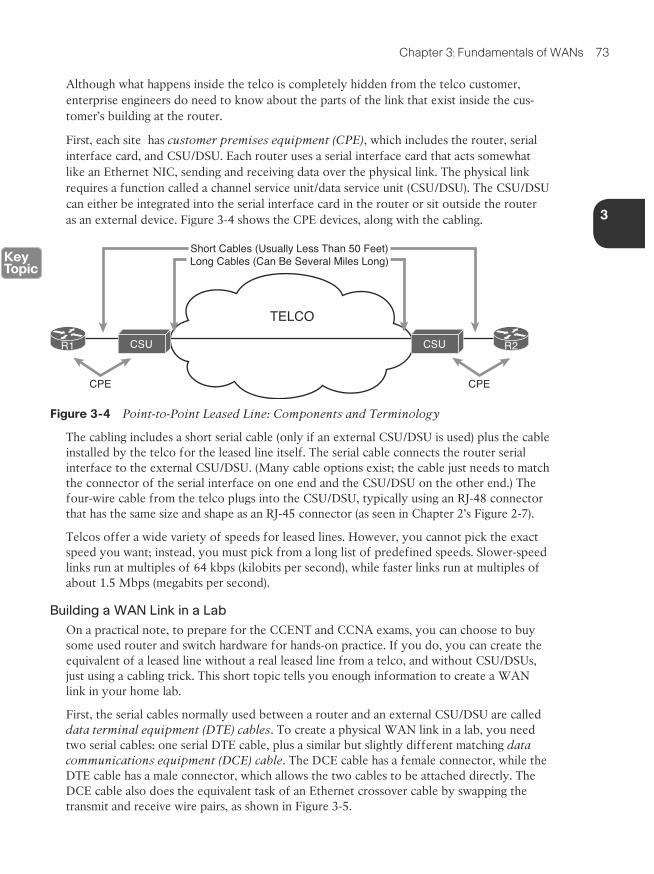
First, each site has customer premises equipment (CPE), which includes the router, serial interface card, and CSU/DSU. Each router uses a serial interface card that acts somewhat like an Ethernet NIC, sending and receiving data over the physical link. The physical link requires a function called a channel service unit/data service unit (CSU/DSU). The CSU/DSU can either be integrated into the serial interface card in the router or sit outside the router as an external device. Figure 3-4 shows the CPE devices, along with the cabling.
CSU CSU
TELCO
CPE CPE
Short Cables (Usually Less Than 50 Feet)Long Cables (Can Be Several Miles Long)
R1 R2
Figure 3-4 Point-to-Point Leased Line: Components and Terminology
The cabling includes a short serial cable (only if an external CSU/DSU is used) plus the cable installed by the telco for the leased line itself. The serial cable connects the router serial interface to the external CSU/DSU. (Many cable options exist; the cable just needs to match the connector of the serial interface on one end and the CSU/DSU on the other end.) The four-wire cable from the telco plugs into the CSU/DSU, typically using an RJ-48 connector that has the same size and shape as an RJ-45 connector (as seen in Chapter 2’s Figure 2-7).
Telcos offer a wide variety of speeds for leased lines. However, you cannot pick the exact speed you want; instead, you must pick from a long list of predefined speeds. Slower-speed links run at multiples of 64 kbps (kilobits per second), while faster links run at multiples of about 1.5 Mbps (megabits per second).
Building a WAN Link in a Lab
On a practical note, to prepare for the CCENT and CCNA exams, you can choose to buy some used router and switch hardware for hands-on practice. If you do, you can create the equivalent of a leased line without a real leased line from a telco, and without CSU/DSUs, just using a cabling trick. This short topic tells you enough information to create a WAN link in your home lab.
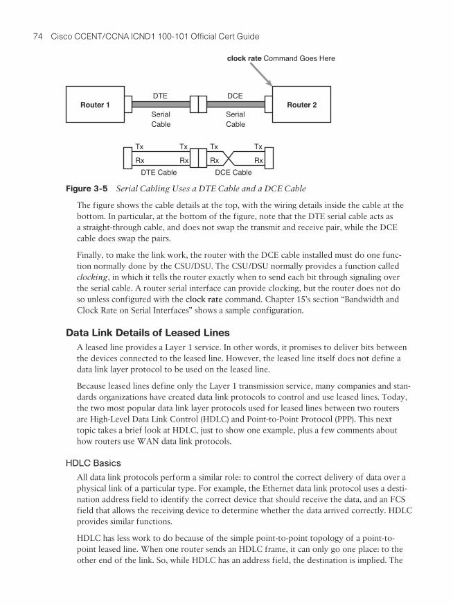
First, the serial cables normally used between a router and an external CSU/DSU are called data terminal equipment (DTE) cables. To create a physical WAN link in a lab, you need two serial cables: one serial DTE cable, plus a similar but slightly different matching data communications equipment (DCE) cable. The DCE cable has a female connector, while the DTE cable has a male connector, which allows the two cables to be attached directly. The DCE cable also does the equivalent task of an Ethernet crossover cable by swapping the transmit and receive wire pairs, as shown in Figure 3-5.
74 Cisco CCENT/CCNA ICND1 100-101 Official Cert Guide
SerialCable
SerialCable
DTE DCE
clock rate Command Goes Here
Tx
Rx
Tx
Rx
Tx
Rx
Tx
RxDTE Cable DCE Cable
Router 2Router 1
Figure 3-5 Serial Cabling Uses a DTE Cable and a DCE Cable
The figure shows the cable details at the top, with the wiring details inside the cable at the bottom. In particular, at the bottom of the figure, note that the DTE serial cable acts as a straight-through cable, and does not swap the transmit and receive pair, while the DCE cable does swap the pairs.
Finally, to make the link work, the router with the DCE cable installed must do one func-tion normally done by the CSU/DSU. The CSU/DSU normally provides a function called clocking, in which it tells the router exactly when to send each bit through signaling over the serial cable. A router serial interface can provide clocking, but the router does not do so unless configured with the clock rate command. Chapter 15’s section “Bandwidth and Clock Rate on Serial Interfaces” shows a sample configuration.
Data Link Details of Leased LinesA leased line provides a Layer 1 service. In other words, it promises to deliver bits between the devices connected to the leased line. However, the leased line itself does not define a data link layer protocol to be used on the leased line.
Because leased lines define only the Layer 1 transmission service, many companies and stan-dards organizations have created data link protocols to control and use leased lines. Today, the two most popular data link layer protocols used for leased lines between two routers are High-Level Data Link Control (HDLC) and Point-to-Point Protocol (PPP). This next topic takes a brief look at HDLC, just to show one example, plus a few comments about how routers use WAN data link protocols.
HDLC Basics
All data link protocols perform a similar role: to control the correct delivery of data over a physical link of a particular type. For example, the Ethernet data link protocol uses a desti-nation address field to identify the correct device that should receive the data, and an FCS field that allows the receiving device to determine whether the data arrived correctly. HDLC provides similar functions.
HDLC has less work to do because of the simple point-to-point topology of a point-to-point leased line. When one router sends an HDLC frame, it can only go one place: to the other end of the link. So, while HDLC has an address field, the destination is implied. The
3
Chapter 3: Fundamentals of WANs 75
idea is sort of like when I have lunch with my friend Gary, and only Gary. I do not need to start every sentence with “Hey Gary”—he knows I am talking to him.
NOTE In case you wonder why HDLC has an address field at all, in years past, the telcos offered multidrop circuits. These circuits included more than two devices, so there was more than one possible destination, requiring an address field to identify the correct destination.
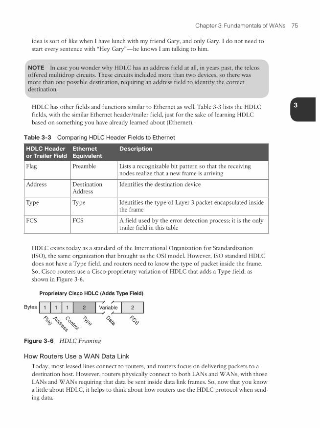
HDLC has other fields and functions similar to Ethernet as well. Table 3-3 lists the HDLC fields, with the similar Ethernet header/trailer field, just for the sake of learning HDLC based on something you have already learned about (Ethernet).
Table 3-3 Comparing HDLC Header Fields to Ethernet
HDLC Header or Trailer Field
Ethernet Equivalent
Description
Flag Preamble Lists a recognizable bit pattern so that the receiving nodes realize that a new frame is arriving
Address Destination Address
Identifies the destination device
Type Type Identifies the type of Layer 3 packet encapsulated inside the frame
FCS FCS A field used by the error detection process; it is the only trailer field in this table
HDLC exists today as a standard of the International Organization for Standardization (ISO), the same organization that brought us the OSI model. However, ISO standard HDLC does not have a Type field, and routers need to know the type of packet inside the frame. So, Cisco routers use a Cisco-proprietary variation of HDLC that adds a Type field, as shown in Figure 3-6.
Proprietary Cisco HDLC (Adds Type Field)
Bytes 1 11 2 Variable 2Flag
Address
Control
DataFCS
Type
Figure 3-6 HDLC Framing
How Routers Use a WAN Data Link
Today, most leased lines connect to routers, and routers focus on delivering packets to a destination host. However, routers physically connect to both LANs and WANs, with those LANs and WANs requiring that data be sent inside data link frames. So, now that you know a little about HDLC, it helps to think about how routers use the HDLC protocol when send-ing data.
76 Cisco CCENT/CCNA ICND1 100-101 Official Cert Guide
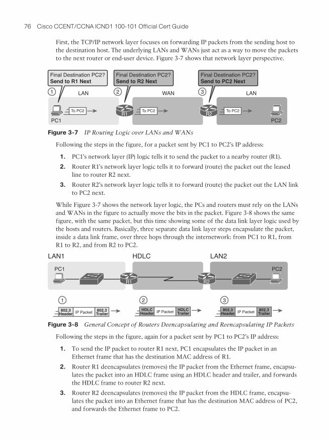
First, the TCP/IP network layer focuses on forwarding IP packets from the sending host to the destination host. The underlying LANs and WANs just act as a way to move the packets to the next router or end-user device. Figure 3-7 shows that network layer perspective.
PC2PC1
WAN LANLAN1 2 3
Final Destination PC2?Send to R1 Next
Final Destination PC2?Send to R2 Next
Final Destination PC2?Send to PC2 Next
To PC2 To PC2 To PC2R1 R2
Figure 3-7 IP Routing Logic over LANs and WANs
Following the steps in the figure, for a packet sent by PC1 to PC2’s IP address:
1. PC1’s network layer (IP) logic tells it to send the packet to a nearby router (R1).
2. Router R1’s network layer logic tells it to forward (route) the packet out the leased line to router R2 next.
3. Router R2’s network layer logic tells it to forward (route) the packet out the LAN link to PC2 next.
While Figure 3-7 shows the network layer logic, the PCs and routers must rely on the LANs and WANs in the figure to actually move the bits in the packet. Figure 3-8 shows the same figure, with the same packet, but this time showing some of the data link layer logic used by the hosts and routers. Basically, three separate data link layer steps encapsulate the packet, inside a data link frame, over three hops through the internetwork: from PC1 to R1, from R1 to R2, and from R2 to PC2.
PC1
LAN1 HDLC LAN2
PC2
R1 R2
802.3 802.3IP Packet
1 2 3
Header TrailerHDLC HDLCIP PacketHeader Trailer
802.3 802.3IP PacketHeader Trailer
Figure 3-8 General Concept of Routers Deencapsulating and Reencapsulating IP Packets
Following the steps in the figure, again for a packet sent by PC1 to PC2’s IP address:
1. To send the IP packet to router R1 next, PC1 encapsulates the IP packet in an Ethernet frame that has the destination MAC address of R1.
2. Router R1 deencapsulates (removes) the IP packet from the Ethernet frame, encapsu-lates the packet into an HDLC frame using an HDLC header and trailer, and forwards the HDLC frame to router R2 next.
3. Router R2 deencapsulates (removes) the IP packet from the HDLC frame, encapsu-lates the packet into an Ethernet frame that has the destination MAC address of PC2, and forwards the Ethernet frame to PC2.
3
Chapter 3: Fundamentals of WANs 77
In summary, a leased line with HDLC creates a WAN link between two routers so that they can forward packets for the devices on the attached LANs. The leased line itself provides the physical means to transmit the bits, in both directions. The HDLC frames provide the means to encapsulate the network layer packet correctly so that it crosses the link between routers.
Leased lines have many benefits that have led to their relatively long life in the WAN mar-ketplace. These lines are simple for the customer, are widely available, are of high quality, and are private. However, they do have some negatives as well compared to newer WAN technologies, including a higher cost and typically longer lead times to get the service installed. The next section looks at an alternative WAN technology used in some examples in this book: Ethernet.
Ethernet as a WAN TechnologyFor the first several decades of the existence of Ethernet, Ethernet was only appropriate for LANs. The restrictions on cable lengths and devices might allow a LAN that stretched a kilometer or two, to support a campus LAN, but that was the limit.
As time passed, the IEEE improved Ethernet standards in ways that made Ethernet a reason-able WAN technology. For example, the 1000BASE-LX standard uses single-mode fiber cabling, with support for a 5-km cable length; the 1000BASE-ZX standard supports an even longer 70-km cable length. As time went by, and as the IEEE improved cabling distances for fiber Ethernet links, Ethernet became a reasonable WAN technology.
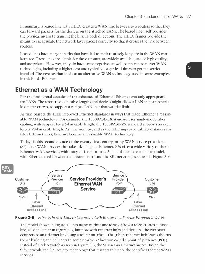
Today, in this second decade of the twenty-first century, many WAN service providers (SP) offer WAN services that take advantage of Ethernet. SPs offer a wide variety of these Ethernet WAN services, with many different names. But all of them use a similar model, with Ethernet used between the customer site and the SP’s network, as shown in Figure 3-9.
FiberEthernet
Access Link
Service Provider’sEthernet WAN
ServiceR1 R2SP1 SP2
Service Provider
PoP
Service Provider
PoPCustomer
SiteCustomer
Site
FiberEthernet
Access Link
CPE CPE
Figure 3-9 Fiber Ethernet Link to Connect a CPE Router to a Service Provider’s WAN
The model shown in Figure 3-9 has many of the same ideas of how a telco creates a leased line, as seen earlier in Figure 3-3, but now with Ethernet links and devices. The customer connects to an Ethernet link using a router interface. The (fiber) Ethernet link leaves the cus-tomer building and connects to some nearby SP location called a point of presence (POP). Instead of a telco switch as seen in Figure 3-3, the SP uses an Ethernet switch. Inside the SP’s network, the SP uses any technology that it wants to create the specific Ethernet WAN services.
78 Cisco CCENT/CCNA ICND1 100-101 Official Cert Guide
Ethernet WANs that Create a Layer 2 ServiceThe WAN services implied by Figure 3-9 include a broad number of services, with a lot of complex networking concepts needed to understand those services. Yet, we sit here at the third chapter of what is probably your first Cisco certification book, so clearly, getting into depth on these WAN services makes little sense. So, for the purposes of the CCENT certi-fication, this book focuses on one specific Ethernet WAN service that can be easily under-stood if you understand how Ethernet LANs work.
NOTE For perspective about the broad world of the service provider network shown in Figure 3-9, consider the Cisco certification paths for a moment. Cisco has CCNA, CCNP, and CCIE certifications in many areas: routing and switching, voice, security, and so on. Two paths—Service Provider and Service Provider Operations—focus on technologies and tasks in the service provider arena. See www.cisco.com/go/certifications for more details.
The one Ethernet WAN service used for CCENT and CCNA Routing and Switching exam-ples goes by two names: Ethernet emulation and Ethernet over MPLS (EoMPLS). Ethernet emulation is a general term, meaning that the service acts like one Ethernet link. EoMPLS refers to Multiprotocol Label Switching (MPLS), which is one technology that can be used inside the SP’s cloud. This book will refer to this specific service either as Ethernet emula-tion or EoMPLS.
The type of EoMPLS service discussed in this book gives the customer an Ethernet link between two sites. In other words, the EoMPLS service provides
■ A point-to-point connection between two customer devices
■ Behavior as if a fiber Ethernet link existed between the two devices
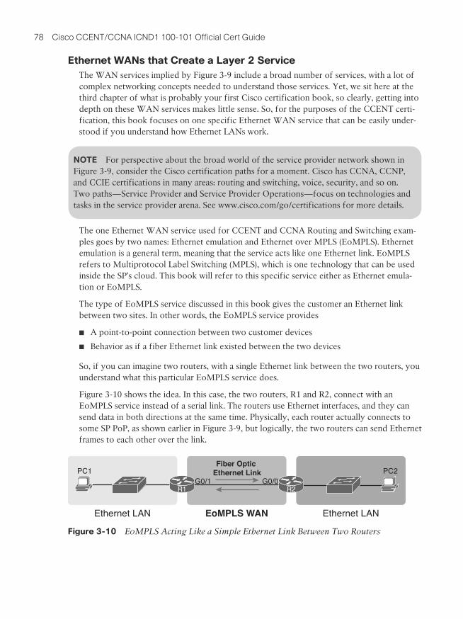
So, if you can imagine two routers, with a single Ethernet link between the two routers, you understand what this particular EoMPLS service does.
Figure 3-10 shows the idea. In this case, the two routers, R1 and R2, connect with an EoMPLS service instead of a serial link. The routers use Ethernet interfaces, and they can send data in both directions at the same time. Physically, each router actually connects to some SP PoP, as shown earlier in Figure 3-9, but logically, the two routers can send Ethernet frames to each other over the link.
PC1
Ethernet LAN EoMPLS WAN Ethernet LAN
PC2
R1 R2
Fiber Optic Ethernet Link
G0/0G0/1
Figure 3-10 EoMPLS Acting Like a Simple Ethernet Link Between Two Routers
3
Chapter 3: Fundamentals of WANs 79
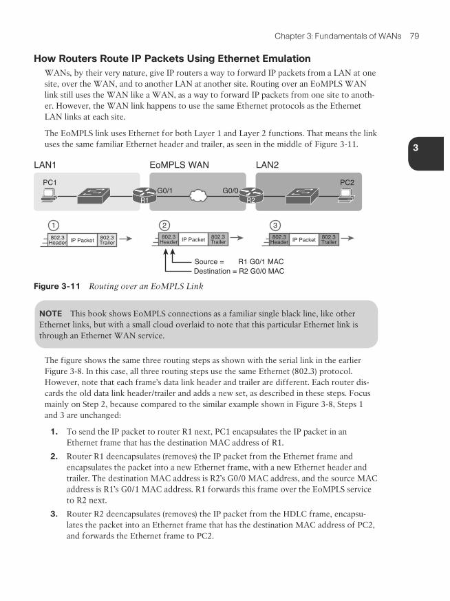
How Routers Route IP Packets Using Ethernet EmulationWANs, by their very nature, give IP routers a way to forward IP packets from a LAN at one site, over the WAN, and to another LAN at another site. Routing over an EoMPLS WAN link still uses the WAN like a WAN, as a way to forward IP packets from one site to anoth-er. However, the WAN link happens to use the same Ethernet protocols as the Ethernet LAN links at each site.
The EoMPLS link uses Ethernet for both Layer 1 and Layer 2 functions. That means the link uses the same familiar Ethernet header and trailer, as seen in the middle of Figure 3-11.
PC1
LAN1 EoMPLS WAN LAN2
PC2
R1 R2
1 2 3
G0/0G0/1
Source = R1 G0/1 MACDestination = R2 G0/0 MAC
802.3 802.3IP PacketHeader Trailer802.3 802.3IP PacketHeader Trailer
802.3 802.3IP PacketHeader Trailer
Figure 3-11 Routing over an EoMPLS Link
NOTE This book shows EoMPLS connections as a familiar single black line, like other Ethernet links, but with a small cloud overlaid to note that this particular Ethernet link is through an Ethernet WAN service.
The figure shows the same three routing steps as shown with the serial link in the earlier Figure 3-8. In this case, all three routing steps use the same Ethernet (802.3) protocol. However, note that each frame’s data link header and trailer are different. Each router dis-cards the old data link header/trailer and adds a new set, as described in these steps. Focus mainly on Step 2, because compared to the similar example shown in Figure 3-8, Steps 1 and 3 are unchanged:
1. To send the IP packet to router R1 next, PC1 encapsulates the IP packet in an Ethernet frame that has the destination MAC address of R1.
2. Router R1 deencapsulates (removes) the IP packet from the Ethernet frame and encapsulates the packet into a new Ethernet frame, with a new Ethernet header and trailer. The destination MAC address is R2’s G0/0 MAC address, and the source MAC address is R1’s G0/1 MAC address. R1 forwards this frame over the EoMPLS service to R2 next.
3. Router R2 deencapsulates (removes) the IP packet from the HDLC frame, encapsu-lates the packet into an Ethernet frame that has the destination MAC address of PC2, and forwards the Ethernet frame to PC2.
80 Cisco CCENT/CCNA ICND1 100-101 Official Cert Guide
Accessing the InternetMany people begin their CCENT and CCNA study never having heard of leased lines, but many people have heard of two other WAN technologies used to gain access to the Internet: digital subscriber line (DSL) and cable. These two WAN technologies do not replace leased lines in all cases, but they do play an important role in the specific case of creating a WAN connection between a home or office and the Internet.
This last major section of the chapter begins by introducing the basic networking concepts behind the Internet, followed with some specifics of how DSL and cable provide a way to send data to/from the Internet.
The Internet as a Large WANThe Internet is an amazing cultural phenomenon. Most of us use it every day. We post mes-sages on social media sites, we search for information using a search engine like Google, and we send emails. We use apps on our phones to pull down information, like weather reports, maps, and movie reviews. We use the Internet to purchase physical products and to buy and download digital products like music and videos. The Internet has created completely new things to do and changed the old ways of living life compared to a generation ago.
However, if you instead focus on the networking technology that creates the Internet, the Internet is simply one huge TCP/IP network. In fact, the name “Internet” comes from the core network layer protocol: Internet Protocol. The Internet includes many LANs, and because the Internet spans the globe, it of course needs WAN links to connect different sites.
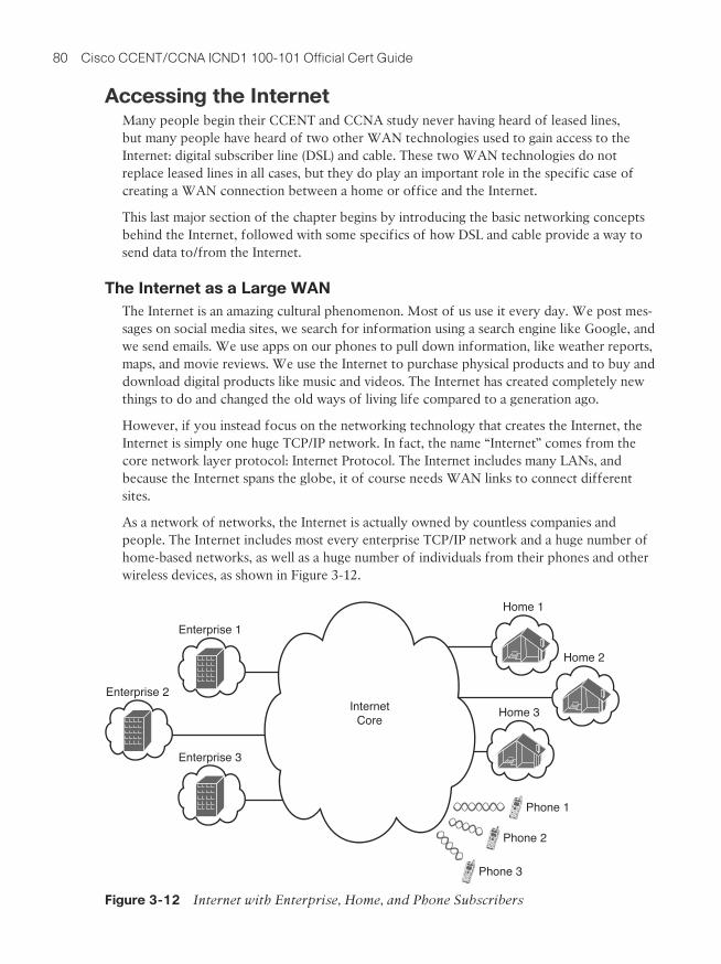
As a network of networks, the Internet is actually owned by countless companies and people. The Internet includes most every enterprise TCP/IP network and a huge number of home-based networks, as well as a huge number of individuals from their phones and other wireless devices, as shown in Figure 3-12.
Enterprise 1
Home 1
Home 2
Home 3
Phone 1
Enterprise 3
Enterprise 2Internet
Core
Phone 2
Phone 3
Figure 3-12 Internet with Enterprise, Home, and Phone Subscribers
3
Chapter 3: Fundamentals of WANs 81
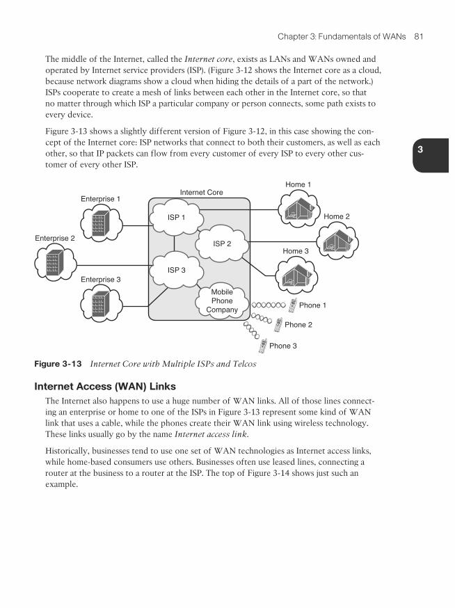
The middle of the Internet, called the Internet core, exists as LANs and WANs owned and operated by Internet service providers (ISP). (Figure 3-12 shows the Internet core as a cloud, because network diagrams show a cloud when hiding the details of a part of the network.) ISPs cooperate to create a mesh of links between each other in the Internet core, so that no matter through which ISP a particular company or person connects, some path exists to every device.
Figure 3-13 shows a slightly different version of Figure 3-12, in this case showing the con-cept of the Internet core: ISP networks that connect to both their customers, as well as each other, so that IP packets can flow from every customer of every ISP to every other cus-tomer of every other ISP.
Phone 1
Phone 2
Phone 3
Enterprise 1
Home 1
Home 2
Home 3
Enterprise 3
Enterprise 2
MobilePhone
Company
ISP 2
ISP 3
Internet Core
ISP 1
Figure 3-13 Internet Core with Multiple ISPs and Telcos
Internet Access (WAN) LinksThe Internet also happens to use a huge number of WAN links. All of those lines connect-ing an enterprise or home to one of the ISPs in Figure 3-13 represent some kind of WAN link that uses a cable, while the phones create their WAN link using wireless technology. These links usually go by the name Internet access link.
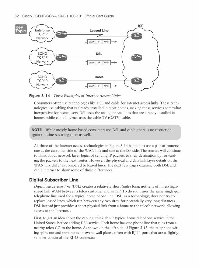
Historically, businesses tend to use one set of WAN technologies as Internet access links, while home-based consumers use others. Businesses often use leased lines, connecting a router at the business to a router at the ISP. The top of Figure 3-14 shows just such an example.
82 Cisco CCENT/CCNA ICND1 100-101 Official Cert Guide
WAN WANIP
EnterpriseTCP/IPNetwork
Leased Line
WAN WANIP
SOHOTCP/IPNetwork
DSL
WAN WANIP
SOHOTCP/IPNetwork
ISP
Cable
Figure 3-14 Three Examples of Internet Access Links
Consumers often use technologies like DSL and cable for Internet access links. These tech-nologies use cabling that is already installed in most homes, making these services somewhat inexpensive for home users. DSL uses the analog phone lines that are already installed in homes, while cable Internet uses the cable TV (CATV) cable.
NOTE While mostly home-based consumers use DSL and cable, there is no restriction against businesses using them as well.
All three of the Internet access technologies in Figure 3-14 happen to use a pair of routers: one at the customer side of the WAN link and one at the ISP side. The routers will continue to think about network layer logic, of sending IP packets to their destination by forward-ing the packets to the next router. However, the physical and data link layer details on the WAN link differ as compared to leased lines. The next few pages examine both DSL and cable Internet to show some of those differences.
Digital Subscriber LineDigital subscriber line (DSL) creates a relatively short (miles long, not tens of miles) high-speed link WAN between a telco customer and an ISP. To do so, it uses the same single-pair telephone line used for a typical home phone line. DSL, as a technology, does not try to replace leased lines, which run between any two sites, for potentially very long distances. DSL instead just provides a short physical link from a home to the telco’s network, allowing access to the Internet. .
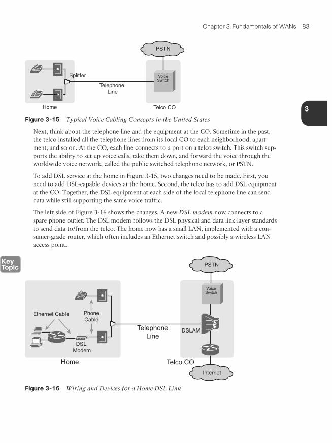
First, to get an idea about the cabling, think about typical home telephone service in the United States, before adding DSL service. Each home has one phone line that runs from a nearby telco CO to the home. As shown on the left side of Figure 3-15, the telephone wir-ing splits out and terminates at several wall plates, often with RJ-11 ports that are a slightly skinnier cousin of the RJ-45 connector.
3
Chapter 3: Fundamentals of WANs 83
Home Telco CO
Splitter
Telephone Line
VoiceSwitch
PSTN
Figure 3-15 Typical Voice Cabling Concepts in the United States
Next, think about the telephone line and the equipment at the CO. Sometime in the past, the telco installed all the telephone lines from its local CO to each neighborhood, apart-ment, and so on. At the CO, each line connects to a port on a telco switch. This switch sup-ports the ability to set up voice calls, take them down, and forward the voice through the worldwide voice network, called the public switched telephone network, or PSTN.
To add DSL service at the home in Figure 3-15, two changes need to be made. First, you need to add DSL-capable devices at the home. Second, the telco has to add DSL equipment at the CO. Together, the DSL equipment at each side of the local telephone line can send data while still supporting the same voice traffic.
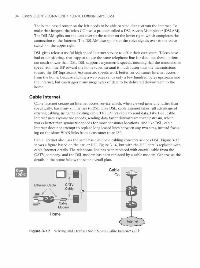
The left side of Figure 3-16 shows the changes. A new DSL modem now connects to a spare phone outlet. The DSL modem follows the DSL physical and data link layer standards to send data to/from the telco. The home now has a small LAN, implemented with a con-sumer-grade router, which often includes an Ethernet switch and possibly a wireless LAN access point.
VoiceSwitch
PSTN
PhoneCable
DSL Modem
Home Telco CO
DSLAM
Ethernet Cable
Internet
TelephoneLine
Figure 3-16 Wiring and Devices for a Home DSL Link
84 Cisco CCENT/CCNA ICND1 100-101 Official Cert Guide
The home-based router on the left needs to be able to send data to/from the Internet. To make that happen, the telco CO uses a product called a DSL Access Multiplexer (DSLAM). The DSLAM splits out the data over to the router on the lower right, which completes the connection to the Internet. The DSLAM also splits out the voice signals over to the voice switch on the upper right.
DSL gives telcos a useful high-speed Internet service to offer their customers. Telcos have had other offerings that happen to use the same telephone line for data, but these options ran much slower than DSL. DSL supports asymmetric speeds, meaning that the transmission speed from the ISP toward the home (downstream) is much faster than the transmissions toward the ISP (upstream). Asymmetric speeds work better for consumer Internet access from the home, because clicking a web page sends only a few hundred bytes upstream into the Internet, but can trigger many megabytes of data to be delivered downstream to the home.
Cable InternetCable Internet creates an Internet access service which, when viewed generally rather than specifically, has many similarities to DSL. Like DSL, cable Internet takes full advantage of existing cabling, using the existing cable TV (CATV) cable to send data. Like DSL, cable Internet uses asymmetric speeds, sending data faster downstream than upstream, which works better than symmetric speeds for most consumer locations. And like DSL, cable Internet does not attempt to replace long leased lines between any two sites, instead focus-ing on the short WAN links from a customer to an ISP.
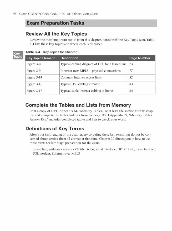
Cable Internet also uses the same basic in-home cabling concepts as does DSL. Figure 3-17 shows a figure based on the earlier DSL Figure 3-16, but with the DSL details replaced with cable Internet details. The telephone line has been replaced with coaxial cable from the CATV company, and the DSL modem has been replaced by a cable modem. Otherwise, the details in the home follow the same overall plan.
CATVCable
Cable Modem
Home
CableCo
Ethernet Cable
Internet
Figure 3-17 Wiring and Devices for a Home Cable Internet Link

3
Chapter 3: Fundamentals of WANs 85
On the CATV company side of the cable Internet service, the CATV company has to split out the data and video, as shown on the right side of the figure. Data flows to the lower right, through a router, while video comes in from video dishes for distribution out to the TVs in people’s homes.
Cable Internet service and DSL directly compete for consumer and small-business Internet access. Generally speaking, while both offer high speeds, cable Internet typically runs at faster speeds than DSL, with DSL providers keeping their prices a little lower to compete. Both support asymmetric speeds, and both provide an “always on” service, in that you can communicate with the Internet without the need to first take some action to start the Internet connection.
86 Cisco CCENT/CCNA ICND1 100-101 Official Cert Guide
Exam Preparation Tasks
Review All the Key TopicsReview the most important topics from this chapter, noted with the Key Topic icon. Table 3-4 lists these key topics and where each is discussed.
Table 3-4 Key Topics for Chapter 3
Key Topic Element Description Page Number
Figure 3-4 Typical cabling diagram of CPE for a leased line 73
Figure 3-9 Ethernet over MPLS—physical connections 77
Figure 3-14 Common Internet access links 82
Figure 3-16 Typical DSL cabling at home 83
Figure 3-17 Typical cable Internet cabling at home 84
Complete the Tables and Lists from MemoryPrint a copy of DVD Appendix M, “Memory Tables,” or at least the section for this chap-ter, and complete the tables and lists from memory. DVD Appendix N, “Memory Tables Answer Key,” includes completed tables and lists to check your work.
Definitions of Key TermsAfter your first reading of the chapter, try to define these key terms, but do not be con-cerned about getting them all correct at that time. Chapter 30 directs you in how to use these terms for late-stage preparation for the exam.
leased line, wide-area network (WAN), telco, serial interface, HDLC, DSL, cable Internet, DSL modem, Ethernet over MPLS

This page intentionally left blank
This chapter covers the following exam topics:
Operation of IP Data Networks
Recognize the purpose and functions of various network devices such as Routers, Switches, Bridges and Hubs.
Select the components required to meet a given network specification.
Predict the data flow between two hosts across a network.
IP Routing Technologies
Differentiate methods of routing and routing protocols
Static vs. Dynamic
Symbols & Numerics/64 prefix length, 702| (pipe function), 212? (question mark), CLI command help, 183/ (slash), prefix subnet mask format, 353
10 Gig Ethernet, 4910BASE-T, 49
bridges, 147hubs, 146switches, 148
10GBASE-T, 49100BASE-LX, 49100BASE-T, 49128-bit IPv6 addresses
configuring on Cisco routers, 735verifying configuration, 739
404 return code (HTTP), 133802.1Q trunking, 241
configuring, 440-444native VLAN, 242
802.3 standard, 49802.3ab standard, 49802.3an standard, 49802.3u standard, 49802.3z standard, 49802.11 standard, 471000BASE-T, 492960 Catalyst switch series. See Cisco
Catalyst 2960 switch
AAAA servers, 206-207abbreviated IPv6 addresses, expanding,
699abbreviating
CLI commands, 414IPv6 addresses, 698-699
ABRs (Area Border Routers), 475access interfaces, 246-250access switches, 160access-class command, 643-644access-list command
eq parameter, 629, 633extended numbered IP ACLs, matching,
626-627interpreting, 617-618log keyword, 615syntax, 607
any/all addresses, matching, 610exact IP address, matching, 607subset of address, matching, 608-609
accessingCisco Catalyst CLI, 176
EXEC modes, navigating, 181-182help features, 182-183password security, 179-180privileged EXEC mode, 180user EXEC mode, 180with SSH, 179with Telnet, 179with the console, 176-178
setup mode, 192ACLs
applyingpractice problems, 616-617to vty line, 643-644
editing with sequence numbers, 637-639extended numbered IP ACLs
adding to configuration, 640-641configuring, 631creating, practice problems, 634-635destination port as packet, 628-629example configuration, 631-634
INDEX
866 ACLs
IPv4 ACLs, practice problems, 616-617
ARIN (American Registry for Internet Numbers), ASNs, 464
ARP (Address Resolution Pro-tocol), 95. See also NDP
role of network layer in DNS name resolution, 112-113
verifying, 510ARP cache, 113ARP Reply message, 113ARP Request messages, 113AS (autonomous systems),
464ASICs (Application Specific
Integrated Circuits), 436ASN (AS number), 464assigning
IP addresses, subnetting rules, 310-311
IPv6 addresses to hosts in subnets, 723-724
IPv6 subnets to internetwork topology, 723
subnets to different loca-tions, 327
VLANs to access interfaces, 247-250
asymmetric speeds, 84authentication
external authentication serv-ers, configuring, 207
local usernames, hiding pass-words, 214
autonegotiation, 162-164, 413
disabling, 164duplex mismatches, 165failure of, 164on hubs, 165
autosummarization, 579Aux ports, configuring, 419
adjacent-layer interactions, 26administrative distance,
468-469administrative mode
(trunking), 252-253administrative mode (VLANs),
256administratively down
interfaces, 415advanced distance vector
routing protocols, 465allowing zero subnets,
448-449always-on service, 85analyzing
Layer 2 forwarding path, 284-287
subnet maskseasy masks, 383practicing, 363-364
answering exam questions, 824-825
any/all addresses, matching with IPv4 ACLs, 610
AP (access point), 47application layer (OSI model),
36TCP/IP networking model,
23-25WWW
DNS resolution, 132-133
URLs, 131applications, TCP/IP, 129
DNS, 125QoS requirements, 129SNMP, 125TFTP, 125well-known port numbers,
125WWW, 125
applyingACLs to vty line, 643-644
matching parameters (access-list com-mand), 626-627
source port as packet, 629-630
standard ACLs, comparing to, 626
guidelines for implementing, 645
matching packets, 603-604deny keyword, 604permit keyword, 604
named ACLs, 635configuring, 636-637numbered ACLs, com-
paring to, 635-636placement of, 602-603standard numbered IPv4
ACLs, 605command syntax, 607,
610example configuration,
611-614first-match logic,
605-607implementing, 610-611list logic, 605
troubleshooting, 614-615adding
lines to numbered ACL con-figuration, 640-641
subnets to VLSM design, 569-571
address classes, 99-103Address field (HDLC), 75address translation, NAT, 659dynamic NAT, 662-663,
668-673PAT, 663-675static NAT, 659, 666-668troubleshooting, 676-677
addressing conventions for Class A, Class B, and Class C networks, 340-341
calculating 867
connectors, 73CPE, 73CSU/DSU, 73data link layer proto-
cols, 74-76DCE, 73DTE, 73serial cable, 73
optical fiber, 161, 278SOHO network installation,
410telco cable, 407UTP
10BASE-T pinouts, 53-55
100BASE-T pinouts, 53-55
1000BASE-T pinouts, 57
categories, 161data transmission on
Ethernet LANs, 51electrical circuits,
creating on Ethernet LANs, 50
Ethernet links, 51-53pinouts, selecting, 56
WAN links, creating in lab, 73-74
calculating. See also derivingIPv6 prefix, 700-703number of hosts
for classful networks, 337-338
per subnet, 313-314, 361-363
number of subnets per inter-network, 311
powers of 2, numeric refer-ence table, 840
range of usable subnet addresses with binary, 382
subnet broadcast addresses, 375, 390
subnet IDs, calculating, 382bootstrap program, 188borrowing bits from host part
for subnetting, 321brain dumps, 830bridges, 147broadcast addresses, 148
of Class B networks, 340Ethernet, 60subnet broadcast address,
375, 378-379, 382, 388-390
broadcast domains, 156-157, 238
design concepts, 239impact on LAN design,
157-158broadcast subnet, 548broadcasts, comparing to
multicasts, 746-747budgeting your time during
exam, 816-820building
extended numbered IP ACLs, practice problems, 634-635
IPv6 addresses with SLAAC, 767-768
list of all subnets in internetwork, 325-326
Ccable Internet, 84-85cable modems, 409-410cabling
CRC errors, 283crossover cables, 55distance limitations on cam-
pus LANs, 161-162EMI, 51Ethernet
fiber-optic, 49UTP, 48
leased lines, 72
Bbandwidth, 128bandwidth metric, 467banners, configuring on Cisco
Catalyst switches, 214-215batch applications, QoS
requirements, 129Bellman-Ford protocols, 465Berners-Lee, Tim, 24best path selection, Dijkstra
SPF algorithm, 471best summary route, selecting,
582-585BIA (burned-in address), 60binary number format
converting to hexadecimal, numeric reference table, 838
default masks for classful networks, 337
IPv6 prefix lengths, calculat-ing, 702
memorization versus calcula-tion, 390-391
practice problems, 379-380range of usable subnet
addresses, calculating, 382
subnet broadcast address, calculating, 378-379, 382
subnet IDs, calculating, 376-381
subnet mask format, 352converting to DDN,
354-356converting to prefix
format, 353-354wildcard masks, 609
blocking state (STP), 152blogs, www.certskills.com,
830Boolean math, 382
subnet broadcast address, calculating, 382
868 calculating
accessing with the console, 176-178
configuration sub-modes, 185-187
debug commands, 184EXEC modes, navigat-
ing between, 181-182
help features, 182-183history buffer com-
mands, 216password security,
179-180privileged EXEC mode,
180show commands, 184user EXEC mode, 180
interfacesconfiguring, 221-223duplex mismatches,
281-282Layer 1 problems,
282-283securing, 228status codes, 277-278
IP addressconfiguring, 217-220verifying, 220-221
MAC address table, Layer 2, 284-287
memory types, 188password encryption, config-
uring, 210-212port security, 287-288
configuring, 223-228verifying, 226-227
ports, supporting Ethernet link types, 53
SSH, configuring, 207-209time-of-day clocks, synchro-
nizing, 646-647usernames, configuring, 206VLANs
mismatched operation-al state, 292-293
CIDR (classless interdomain routing), 353, 656, 691
classless routing protocol implementation, 657
goals of, 657IPv4 address conservation,
658route aggregation, 657
Cisco 2901 ISR, 408Cisco Binary Game, 354Cisco Catalyst 2960 switch.
See also Cisco Catalyst Switches
banners, configuring, 214-215
CLI, 172, 176accessing with SSH,
179accessing with Telnet,
179accessing with the
console, 176-178configuration
submodes, 185-187debug commands, 184EXEC modes, navigat-
ing, 181-182help features, 182-183password security,
179-180privileged EXEC mode,
180securing, 203-206show commands, 184user EXEC mode, 180
LED status indicators, 173-175
Cisco Catalyst switchesCisco IOS Software, setup
mode, 191-192CLI, 176
accessing with SSH, 179
accessing with Telnet, 179
with binary math, 378-379, 382
with Boolean math, 382with decimal math,
388-390versus memorization,
390-391subnet IDs
with binary math, 376-381
with Boolean math, 382with decimal math,
385-387practice problems,
387-388versus memorization,
390-391total subnets in network,
361-363CAM (Content Addressable
Memory), 149campus LANs
access switches, 160core switches, 161distribution switches, 160Ethernet technology,
selecting, 159-160maximum cable lengths,
161-162candidate default routes, 453categories of UTP cabling,
161CCNA certification, practice
exams, 823CDP (Cisco Discovery
Protocol)disabling, 276as troubleshooting tool,
272-275CDP status, examining,
276-277show cdp neighbors
command, 275CEF (Cisco Express Forward-
ing), 437
classful addressing 869
verifying, 739verifying IPv6 host connec-
tivity, 772-775classes of IPv4 networks,
99-103, 658Class A networks
default mask, 335hosts per network, 335loopback address, 340octets in host and net-
work address part, 335
total networks provi-sioned for, 335
unicast IP addresses, 334
valid network numbers, 335
Class B networksbroadcast address, 340default mask, 335hosts per network, 335octets in host and net-
work address part, 335
total networks provi-sioned for, 335
unicast IP addresses, 334
valid network numbers, 335
Class C networksdefault mask, 335hosts per network, 335network IDs, 341octets in host and net-
work address part, 335
total networks provi-sioned for, 335
unicast IP addresses, 334
valid network numbers, 335
classful addressing, 361
command reference, 411consumer-grade, PAT
configuration, 665-666DHCP server
configuring, 496, 501-503
verifying, 503-504dynamic unicast IPv6
addresses, configuring, 742-743
enterprise routers, installing, 406-407
interfaces, 413configuration com-
mands, 413Ethernet interfaces, 413interface status codes,
414-415IP addresses, configur-
ing, 416-417IP addresses, verifying,
417serial interfaces, 413,
417IP routing
CEF, 437fast switching, 436internal processing, 436performance issues, 436
IPv6 addressing, link-local addresses, 744-746
IPv6 routing, enabling, 736-737
ISRs, installing, 408-409operational status, displaying,
419-420routing table, verifying
OSPFv3 routes, 803-804static unicast IPv6 addresses
configuring, 735-736verifying, 737-738
time-of-day clocks, synchro-nizing with NTP, 646-647
unicast IPv6 addressesEUI-64, configuring,
739-741
mismatched VLAN-allowed, 291
verifying state of, 289-290
Cisco Exam Tutorial, 815-816
Cisco IOS SoftwareCLI, 176
accessing with the con-sole, 176-178
comparing on routers and switches, 412
configuration sub-modes, 185-187
debug commands, 184EXEC modes, navigat-
ing between, 181-182
help features, 182-183IPv6 link-local address-
es, creating, 745-746password security,
179-180privileged EXEC mode,
180show commands, 184SSH, accessing, 179Telnet, accessing, 179user EXEC mode, 180
configuration files, 188-190copying, 190-191erasing, 191
rebooting, 180services, disabling, 642-643setup mode, 191-192statistics, displaying, 192-194subnet zero support, 448-
449Cisco Learning Network, 831Cisco-proprietary version of
HDLC, 75Cisco routers
Aux ports, configuring, 419CLI, comparing with Catalyst
switch CLI, 412
870 classful networks
clocking, 74, 417clouds, 19collision domains, 147-148,
155-158collisions, 63, 283commands
abbreviating, 414access-class, 643-644access-list
eq parameter, 629, 633interpreting, 617-618log keyword, 615matching parameters
(extended ACLs), 626-627
syntax, 607, 610clear ip nat translation, 663clear ip ospf process, 484clock rate, 74, 418configuration commands,
185configure terminal, 204context-setting commands,
185copy, 190debug commands, 184default-information
originate, 487description, 221editing, 183encapsulation, 442end, 204erase startup-config, 191EXEC commands, 181exec-timeout, 216-217exit, 187help features, 182-183history buffer commands,
216hostname, 189ifconfig, 506interface loopback, 483interface range, 223, 249ip access-group, 613
clear ip ospf process com-mand, 484
clearingdynamic entries from transla-
tion table (dynamic), 663running config files, 191
CLI, 172accessing, 176
with the console, 176-178
with SSH, 179with Telnet, 179
banners, configuring, 214-215
comparing on routers and switches, 412
configuration mode, 185configuration submodes,
185-187debug commands, 184enable mode, hiding pass-
word, 212-214EXEC modes, navigating
between, 181-182hands-on practice, 829-830help features, 182-183history buffer commands,
216passwords
encryption, configur-ing, 210-212
security, 179-180privileged EXEC mode, 180securing, 203-206security, password protec-
tion, 641-642show commands, 184user EXEC mode, 180usernames, configuring, 206
clients, IPv6dynamic configuration with
DHCPv6, 763-764IPv6 address, building,
767-768clock rate command, 74, 418
classful networks, 103, 334-335
Class A networks, loopback address, 340
default masks, 337first usable address, deriving,
338-340host part, 336hosts per network, calculat-
ing number of, 337-338last usable address, deriving,
338-340multicast addresses, 334network broadcast address,
deriving, 338-340network ID, deriving,
338-340network part, 336private addressing, 658private IP networks, 319-320public classful IP networks,
317-319subnetting
example design, 323-324
host part of IP address, 321
list of all subnets, build-ing, 325-326
mask format, 324-325mask, selecting,
320-321subnet bits, calculating,
322-323subnets of equal size,
373unicast IP addresses, 334
classful routing protocols, 361classless addressing, 361classless routing protocols,
361, 467CIDR implementation, 657VLSM, support for, 564
clear ip nat translation command, 663
898 user EXEC mode
virtual terminal lines, 180VLAN allowed list, trouble-
shooting mismatches, 291VLAN IDs (VLAN identifiers),
239VLANs, 158-159
access interfaces, 246administrative mode, 256broadcast domains, design
concepts, 238-239configuring
allowed VLAN lists, 257-259, 268, 291-292
full configuration, 247-249
shorter configurations, 250-251
trunking configuration, 253-255
forwarding data between, 242-245
Layer 2 forwarding path, analyzing, 286
Layer 3 switching, configur-ing, 444-446
ROAS, configuring, 440-444state of, verifying, 289-290subinterfaces, 440subnet requirements, calcu-
lating, 312subnets, routing between,
439-440tagging, 239troubleshooting, 288-290trunking, 239-240
802.1Q, 24-242allowed VLAN lists,
257-259, 268, 291-292
configuring, 252-255ISL, 241-242mismatched operation-
al state, 292-293
with traceroute com-mand, 515-519
default routers, 508-510DHCP on Cisco routers,
503-504direction of ACLs, 614-615dynamic NAT configuration,
670-673IPv4 settings
DNS, 507-508IP address, 505-506mask configuration,
505-506IPv6 host connectivity,
769-775IPv6 static routes, 787OSPF configuration,
480-483OSPFv3 configuration,
799-801OSPFv3 operation, 798,
803-804port security, 226-227route summarization,
581-582router interface IP addresses,
417state of VLANs, 289-290unicast IPv6 address con-
figuration on routers, 737-739
VLAN trunking configura-tion, 256-257
VLSM with show ip route command, 565-566
version information of IOS, displaying, 192-194
versions of OSPF routing protocols, comparing, 791-794
video applications, QoS requirements, 130
viewingcontents of ARP cache, 113IPv6 host neighbor table,
762
user EXEC mode, 180usernames, configuring on
Cisco Catalyst switches, 206
UTP (unshielded twisted-pair), 48
10BASE-T, 53crossover cable pinouts,
55pinouts, selecting, 56straight-through cable
pinouts, 54-55100BASE-T, 53
crossover cable pinouts, 55
pinouts, selecting, 56straight-through cable
pinouts, 54-551000BASE-T cable pinouts,
57categories, 161data transmission on Ethernet
LANs, 51electrical circuits, creating on
Ethernet LANs, 50EMI, 51Ethernet links, 51-53
Vvalid network numbers
for Class A networks, 335for Class B networks, 335for Class C networks, 335
verifyingARP, 510Cisco Catalyst switch IP
address, 220-221connectivity
with ping command, 511-515
with telnet command, 519
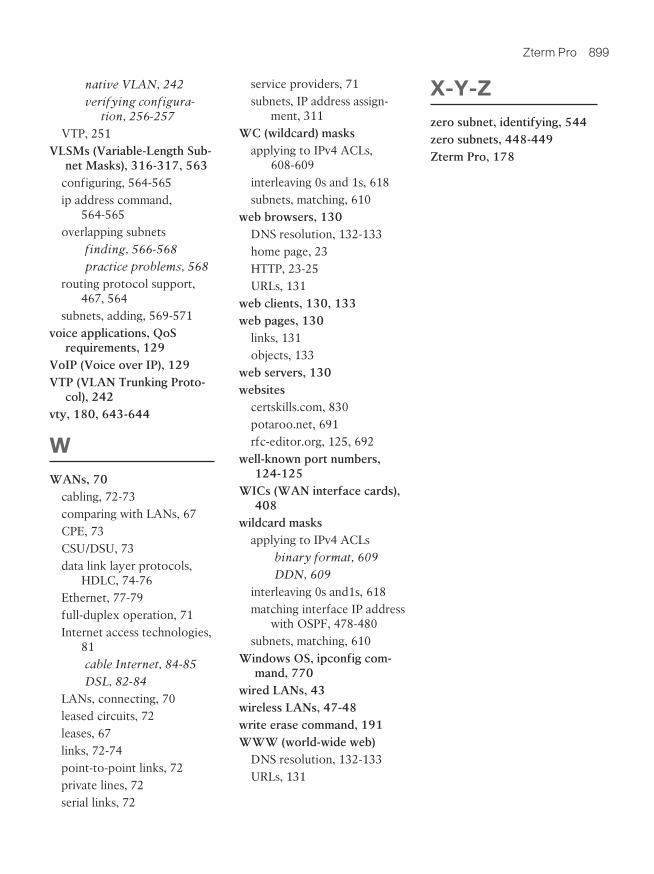
Zterm Pro 899
X-Y-Zzero subnet, identifying, 544zero subnets, 448-449Zterm Pro, 178
service providers, 71subnets, IP address assign-
ment, 311WC (wildcard) masks
applying to IPv4 ACLs, 608-609
interleaving 0s and 1s, 618subnets, matching, 610
web browsers, 130DNS resolution, 132-133home page, 23HTTP, 23-25URLs, 131
web clients, 130, 133web pages, 130
links, 131objects, 133
web servers, 130websites
certskills.com, 830potaroo.net, 691rfc-editor.org, 125, 692
well-known port numbers, 124-125
WICs (WAN interface cards), 408
wildcard masksapplying to IPv4 ACLs
binary format, 609DDN, 609
interleaving 0s and1s, 618matching interface IP address
with OSPF, 478-480subnets, matching, 610
Windows OS, ipconfig com-mand, 770
wired LANs, 43wireless LANs, 47-48write erase command, 191WWW (world-wide web)
DNS resolution, 132-133URLs, 131
native VLAN, 242verifying configura-
tion, 256-257VTP, 251
VLSMs (Variable-Length Sub-net Masks), 316-317, 563
configuring, 564-565ip address command,
564-565overlapping subnets
finding, 566-568practice problems, 568
routing protocol support, 467, 564
subnets, adding, 569-571voice applications, QoS
requirements, 129VoIP (Voice over IP), 129VTP (VLAN Trunking Proto-
col), 242vty, 180, 643-644
WWANs, 70
cabling, 72-73comparing with LANs, 67CPE, 73CSU/DSU, 73data link layer protocols,
HDLC, 74-76Ethernet, 77-79full-duplex operation, 71Internet access technologies,
81cable Internet, 84-85DSL, 82-84
LANs, connecting, 70leased circuits, 72leases, 67links, 72-74point-to-point links, 72private lines, 72serial links, 72