
Cisco ASA 5505, ASA 5510, ASA 5512-X, ASA 5515-X, ASA · PDF fileThe following subsections...
36
Cisco ASA 5505, ASA 5510, ASA 5512-X, ASA 5515-X, ASA 5520, ASA 5525-X, ASA 5540, ASA 5545-X, ASA 5550, ASA 5555-X, ASA 5580-20, ASA 5580-40, ASA 5585-X SSP-10, 5585-X SSP-20, 5585-X SSP-40 and 5585-X SSP-60 Security Appliances FIPS 140-2 Non Proprietary Security Policy Level 2 Validation Version 0.2 June 12, 2014
Transcript of Cisco ASA 5505, ASA 5510, ASA 5512-X, ASA 5515-X, ASA · PDF fileThe following subsections...
Cisco ASA 5505, ASA 5510, ASA 5512-X, ASA 5515-X, ASA 5520, ASA 5525-X, ASA 5540, ASA 5545-X, ASA 5550, ASA 5555-X, ASA 5580-20, ASA 5580-40, ASA 5585-X SSP-10, 5585-X SSP-20, 5585-X SSP-40 and 5585-X
SSP-60 Security Appliances
FIPS 140-2 Non Proprietary Security Policy Level 2 Validation
Version 0.2
June 12, 2014
Table of Contents
1 INTRODUCTION.................................................................................................................... 1
1.1 PURPOSE ............................................................................................................................. 1 1.2 MODULE VALIDATION LEVEL ............................................................................................ 1 1.3 REFERENCES ....................................................................................................................... 1 1.4 TERMINOLOGY ................................................................................................................... 2 1.5 DOCUMENT ORGANIZATION ............................................................................................... 2
2 CISCO ASA 5500 SECURITY APPLIANCES ................................................................... 3
2.1 ASA 5500 AND CRYPTOGRAPHIC MODULE PHYSICAL CHARACTERISTICS ......................... 3 2.2 MODULE INTERFACES ......................................................................................................... 3 2.3 ROLES AND SERVICES ....................................................................................................... 12
User Services ..................................................................................................................................................................... 13 Crypto Officer Services ..................................................................................................................................................... 13
2.4 UNAUTHENTICATED SERVICES ......................................................................................... 14 2.5 CRYPTOGRAPHIC KEY MANAGEMENT .............................................................................. 14 2.6 CRYPTOGRAPHIC ALGORITHMS ........................................................................................ 17
Approved Cryptographic Algorithms ................................................................................................................................ 17 Non-FIPS Approved Algorithms Allowed in FIPS Mode ................................................................................................. 18 Non-Approved Cryptographic Algorithms ........................................................................................................................ 18
2.7 SELF-TESTS ...................................................................................................................... 19 2.8 PHYSICAL SECURITY ........................................................................................................ 20
ASA 5505 Opacity Shield ................................................................................................................................................. 21 ASA 5580-20 and 5580-40 Opacity Shield ....................................................................................................................... 21 ASA 5585-X Opacity Shield ............................................................................................................................................. 23
ASA 5505 ...................................................................................................................................................................... 25 ASA 5510, 5520, 5540 and 5550 .................................................................................................................................. 26 ASA 5512-X and 5515-X ............................................................................................................................................. 26 ASA 5580 ...................................................................................................................................................................... 27 ASA 5585-X ................................................................................................................................................................. 29
Appling Tamper Evidence Labels ..................................................................................................................................... 30
3 SECURE OPERATION ...................................................................................................... 30
3.1 CRYPTO OFFICER GUIDANCE - SYSTEM INITIALIZATION .................................................. 31 3.2 CRYPTO OFFICER GUIDANCE - SYSTEM CONFIGURATION ................................................. 32 3.3 IDENTIFYING ROUTER OPERATION IN AN APPROVED MODE ............................................. 33
© Copyright 2013 Cisco Systems, Inc. 1 This document may be freely reproduced and distributed whole and intact including this Copyright Notice.
1 Introduction
1.1 Purpose This is a non-proprietary Cryptographic Module Security Policy for the Cisco ASA 5505, ASA 5510, ASA 5512-X, ASA 5515-X, ASA 5520, ASA 5525-X, ASA 5540, ASA 5545-X, ASA 5550, ASA 5555-X, ASA 5580-20, ASA 5580-40, ASA 5585-X SSP-10, 5585-X SSP-20, 5585-X SSP-40 and 5585-X SSP-60 Series Adaptive Security Appliances running Firmware 9.1.2; referred to in this document as appliances. This security policy describes how the modules meet the security requirements of FIPS 140-2 Level 2 and how to run the modules in a FIPS 140-2 mode of operation and may be freely distributed. FIPS 140-2 (Federal Information Processing Standards Publication 140-2 — Security Requirements for Cryptographic Modules) details the U.S. Government requirements for cryptographic modules. More information about the FIPS 140-2 standard and validation program is available on the NIST website at http://csrc.nist.gov/groups/STM/index.html.
1.2 Module Validation Level
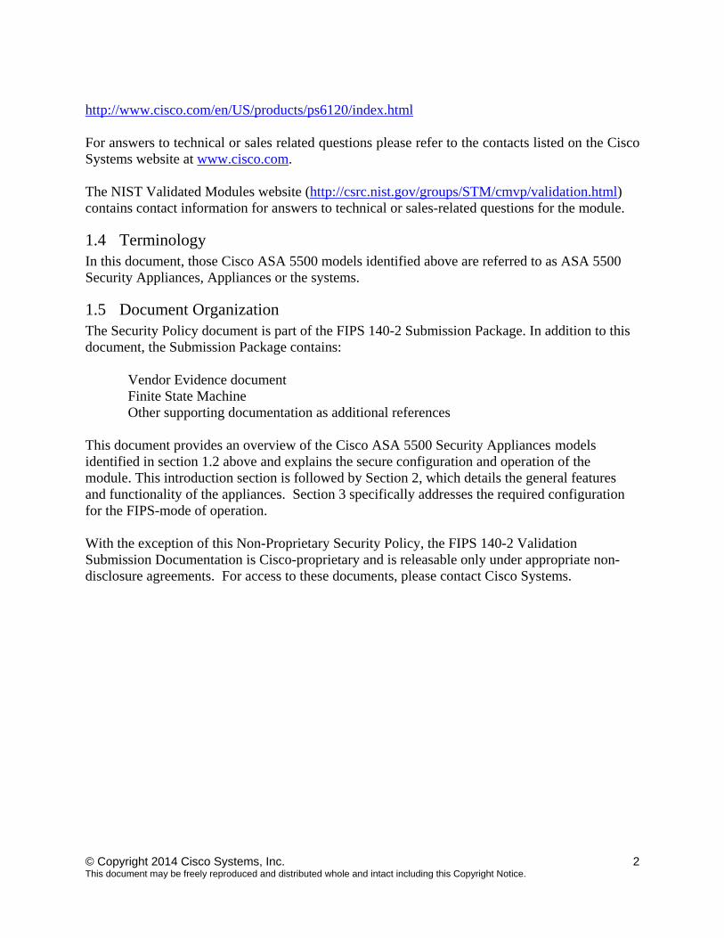
The following table lists the level of validation for each area in the FIPS PUB 140-2.
No. Area Title Level 1 Cryptographic Module Specification 2 2 Cryptographic Module Ports and Interfaces 2 3 Roles, Services, and Authentication 3 4 Finite State Model 2 5 Physical Security 2 6 Operational Environment N/A 7 Cryptographic Key management 2 8 Electromagnetic Interface/Electromagnetic Compatibility 2 9 Self-Tests 2
10 Design Assurance 2 11 Mitigation of Other Attacks N/A Overall module validation level 2
Table 1 Module Validation Level
1.3 References This document deals only with operations and capabilities of those Cisco ASA 5505, ASA 5510, ASA 5512-X, ASA 5515-X, ASA 5520, ASA 5525-X, ASA 5540, ASA 5545-X, ASA 5550, ASA 5555-X, ASA 5580-20, ASA 5580-40, ASA 5585-X SSP-10, 5585-X SSP-20, 5585-X SSP-40 and 5585-X SSP-60 models lists above in section 1.2 in the technical terms of a FIPS 140-2 cryptographic module security policy. More information is available on the routers from the following sources: The Cisco Systems website contains information on the full line of Cisco Systems security. Please refer to the following website: http://www.cisco.com/en/US/prod/collateral/vpndevc/ps6032/ps6094/ps6120/product_data_sheet0900aecd802930c5.html
© Copyright 2014 Cisco Systems, Inc. 2 This document may be freely reproduced and distributed whole and intact including this Copyright Notice.
http://www.cisco.com/en/US/products/ps6120/index.html For answers to technical or sales related questions please refer to the contacts listed on the Cisco Systems website at www.cisco.com.
The NIST Validated Modules website (http://csrc.nist.gov/groups/STM/cmvp/validation.html) contains contact information for answers to technical or sales-related questions for the module.
1.4 Terminology In this document, those Cisco ASA 5500 models identified above are referred to as ASA 5500 Security Appliances, Appliances or the systems.
1.5 Document Organization The Security Policy document is part of the FIPS 140-2 Submission Package. In addition to this document, the Submission Package contains:
Vendor Evidence document Finite State Machine Other supporting documentation as additional references
This document provides an overview of the Cisco ASA 5500 Security Appliances models identified in section 1.2 above and explains the secure configuration and operation of the module. This introduction section is followed by Section 2, which details the general features and functionality of the appliances. Section 3 specifically addresses the required configuration for the FIPS-mode of operation. With the exception of this Non-Proprietary Security Policy, the FIPS 140-2 Validation Submission Documentation is Cisco-proprietary and is releasable only under appropriate non-disclosure agreements. For access to these documents, please contact Cisco Systems.
© Copyright 2014 Cisco Systems, Inc. 3 This document may be freely reproduced and distributed whole and intact including this Copyright Notice.
2 Cisco ASA 5500 Security Appliances
The Cisco ASA 5500 Security Appliances leverage Cisco's expertise in security and VPN solutions, and integrates the latest technologies from Cisco PIX 500 series security appliances, Cisco IPS 4200 Series Intrusion Prevention Systems, and Cisco VPN 3000 series concentrators. The following subsections describe the physical characteristics of the ASA 5500 appliances. Cisco ASA 5500 Series Adaptive Security Appliances integrate world-class firewall, unified communications security, VPN, IPS, and content security services in a unified platform.
2.1 ASA 5500 and Cryptographic Module Physical Characteristics The Cisco ASA 5500 Security Appliances delivers enterprise-class security for medium business-to-enterprise networks in a modular, purpose-built appliance. Its versatile one-rack unit (1RU, ASA 5505, 5510, 5512, 5515, 5520, 5525, 5540, 5545, 5550 and 5555), two-rack unit (2RU, ASA 5585-10, 5585-20, 5585-40 and 5585-60) and four-rack unit (4RU, ASA 5580-20 and 5580-40) design supports 10/100/1000 Gigabit Ethernet ports interfaces (on the ASA 5505, 5510, 5512, 5515, 5520, 5525, 5540, 5545, 5550 and 5555), 1 10/100 Fast Ethernet ports Management interface, and 4 10/100/1000 Gigabit Ethernet ports RJ45 interfaces, 4 Port Gigabit Ethernet ports fiber, and 2 10/100/1000 Gigabit Ethernet ports Management interface (on the ASA 5580 and ASA 5585-X) making it an excellent choice for businesses requiring a cost-effective, resilient security solution with demilitarized zone (DMZ) support. The following subsections describe the physical characteristics of the Cisco ASA 5505, ASA 5510, ASA 5512-X, ASA 5515-X, ASA 5520, ASA 5525-X, ASA 5540, ASA 5545-X, ASA 5550, ASA 5555-X, ASA 5580-20, ASA 5580-40, ASA 5585-X SSP-10, 5585-X SSP-20, 5585-X SSP-40 and 5585-X SSP-60 which contains a multiple-chip standalone cryptographic module with the cryptographic boundary defined as-the modules’ chassis along with the opacity shields. This module is used to support Remote Access VPN With TLSv1/ DTLSv1 and IKEv2/ ESPv3, Secure Shell SSHv2, Secure Sockets Layer (TLS/TLSv1), SNMPv3 and IKE v2 Site-to-Site VPN (with IKEv1 / ESPv1, IKEv2 / ESPv3 & manual keying) with Suite B. These protocols are acceptable under FIPS 140-2 but are non-compliant for SP 800-135.
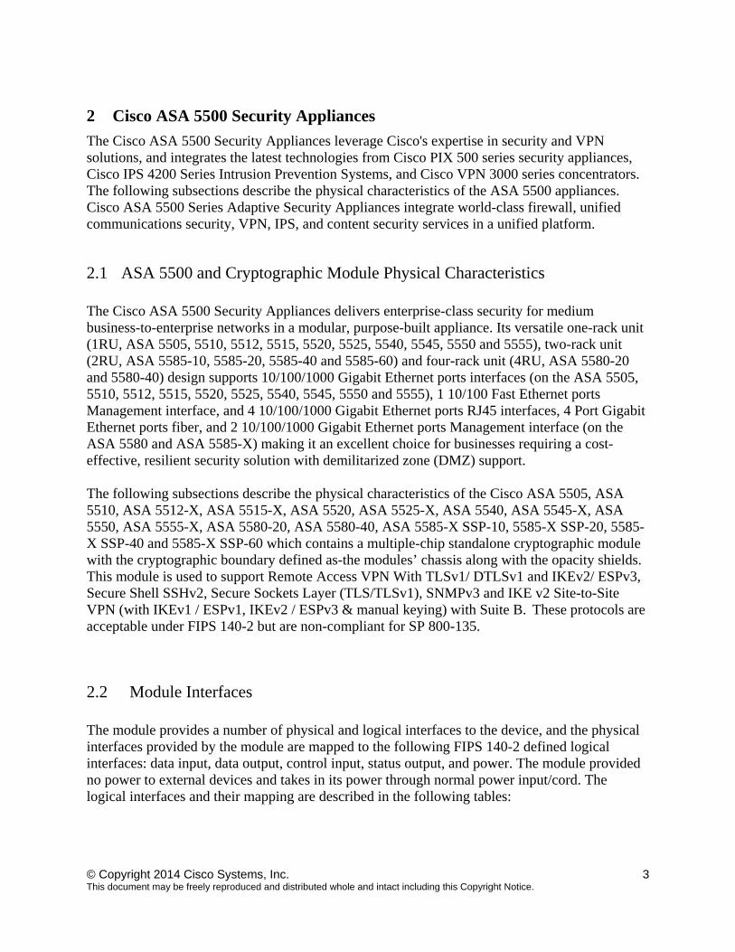
2.2 Module Interfaces The module provides a number of physical and logical interfaces to the device, and the physical interfaces provided by the module are mapped to the following FIPS 140-2 defined logical interfaces: data input, data output, control input, status output, and power. The module provided no power to external devices and takes in its power through normal power input/cord. The logical interfaces and their mapping are described in the following tables:
© Copyright 2014 Cisco Systems, Inc. 4 This document may be freely reproduced and distributed whole and intact including this Copyright Notice.
FIPS 140-2 Logical Interface
ASA 5505 Physical Interface
ASA 5510, 5520, 5540 Physical Interface
ASA 5512, 5515, 5525, 5545, 5555 Physical Interface
ASA 5550 Physical Interface
ASA 55 Physical Interface
ASA 5585 Physical Interface
Data Input Interface
Ethernet ports Console Port
Ethernet ports MGMT Port Console Port
Ethernet ports MGMT Port Console Port
Ethernet ports MGMT Port Console Port
Ethernet ports MGMT Port Console Port
Ethernet ports MGMT Port Console Port
Data Output Interface
Ethernet ports Console Port
Ethernet ports MGMT Port Console Port
Ethernet ports MGMT Port Console Port
Ethernet ports MGMT Port Console Port
Ethernet ports MGMT Port Console Port
Ethernet ports MGMT Port Console Port
Control Input Interface
Ethernet ports Reset Switch Console Port
Ethernet ports MGMT Port Console Port
Ethernet ports MGMT Port Power Switch Console Port
Ethernet ports MGMT Port Power Switch Console Port Reset Switch
Ethernet ports MGMT Port Console Port Reset Switch
Ethernet ports MGMT Port Console Port Reset Switch
Status Output Interface
Ethernet ports LEDs Console Port
Ethernet ports MGMT Port LEDs Console Port
Ethernet ports MGMT Port LEDs Console Port
Ethernet ports MGMT Port LEDs Console Port
Ethernet ports MGMT Port LEDs Console Port
Ethernet ports MGMT Port LEDs Console Port
Power Interface
Power Plug Power Plug Power Plug Power Plug Power Plug Power Plug
Unused Interface
USB Port USB Port Compact Flash Slot (disabled by TEL) Aux Port
USB Port
USB Port Compact Flash Slot (disabled by TEL) Aux Port
USB Port USB Port Aux Port
Please notice that USB port on each module and Aux port on each 5510/5520/5540/5550 module are non-functional.
Table 2 Module Interfaces
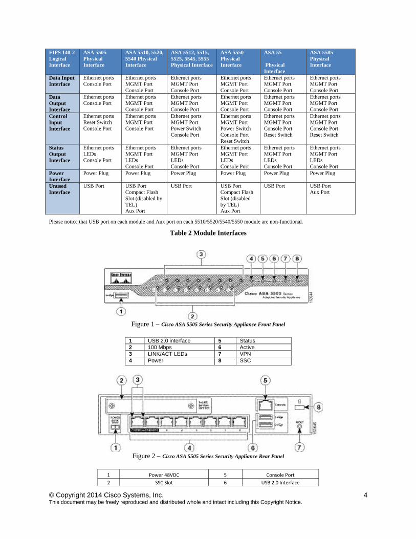
Figure 1 – Cisco ASA 5505 Series Security Appliance Front Panel
1 USB 2.0 interface 5 Status 2 100 Mbps 6 Active 3 LINK/ACT LEDs 7 VPN 4 Power 8 SSC
Figure 2 – Cisco ASA 5505 Series Security Appliance Rear Panel
1 Power 48VDC 5 Console Port
2 SSC Slot 6 USB 2.0 Interface
© Copyright 2014 Cisco Systems, Inc. 5 This document may be freely reproduced and distributed whole and intact including this Copyright Notice.
3 Network Interface LEDs 7 Reset Button
4 Network Interfaces 8 Lock Slot
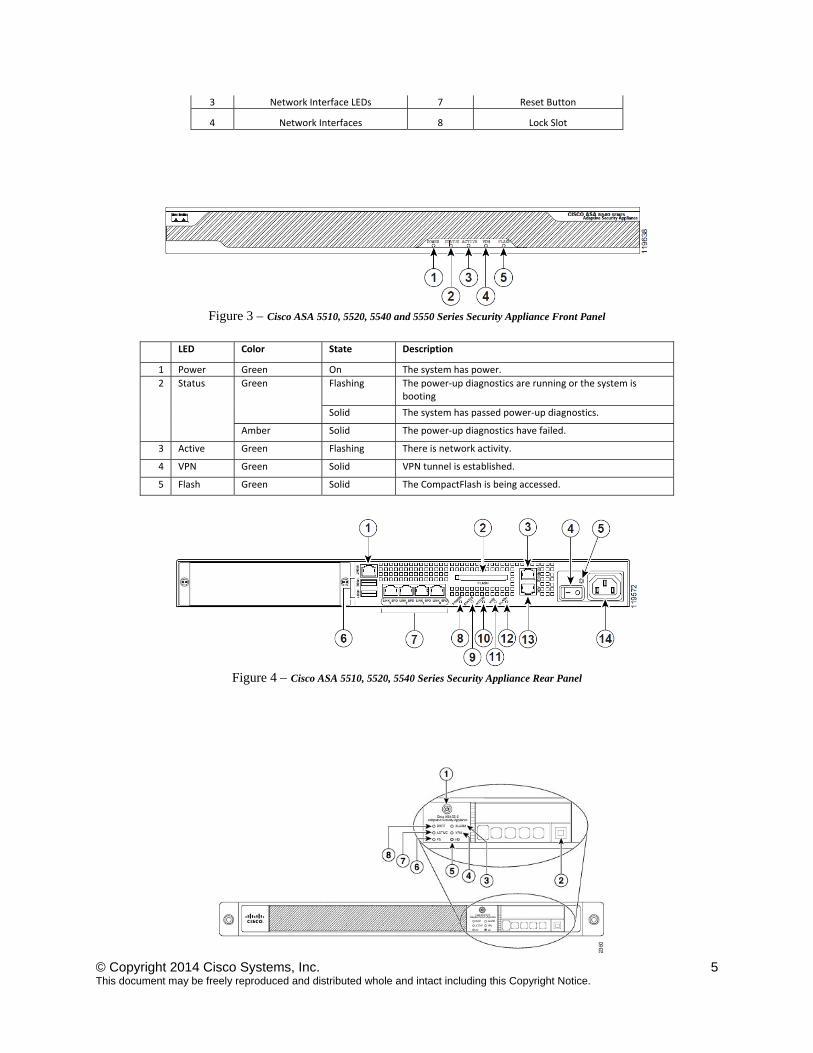
Figure 3 – Cisco ASA 5510, 5520, 5540 and 5550 Series Security Appliance Front Panel
LED Color State Description
1 Power Green On The system has power.
2 Status Green Flashing The power‐up diagnostics are running or the system is booting
Solid The system has passed power‐up diagnostics.
Amber Solid The power‐up diagnostics have failed.
3 Active Green Flashing There is network activity.
4 VPN Green Solid VPN tunnel is established.
5 Flash Green Solid The CompactFlash is being accessed.
Figure 4 – Cisco ASA 5510, 5520, 5540 Series Security Appliance Rear Panel
© Copyright 2014 Cisco Systems, Inc. 6 This document may be freely reproduced and distributed whole and intact including this Copyright Notice.
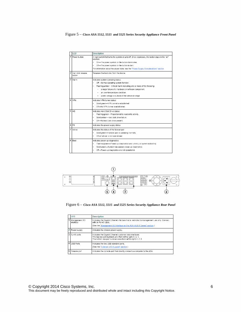
Figure 5 – Cisco ASA 5512, 5515 and 5525 Series Security Appliance Front Panel
Figure 6 – Cisco ASA 5512, 5515 and 5525 Series Security Appliance Rear Panel
© Copyright 2014 Cisco Systems, Inc. 7 This document may be freely reproduced and distributed whole and intact including this Copyright Notice.
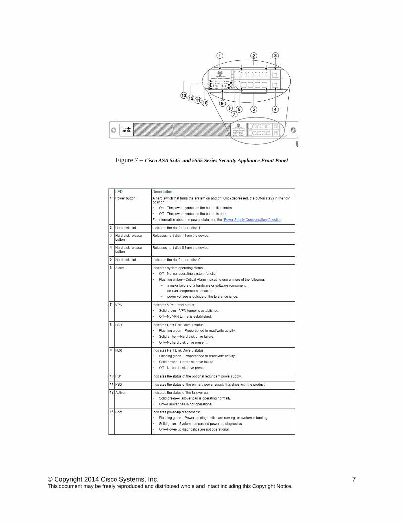
Figure 7 – Cisco ASA 5545 and 5555 Series Security Appliance Front Panel
© Copyright 2014 Cisco Systems, Inc. 8 This document may be freely reproduced and distributed whole and intact including this Copyright Notice.
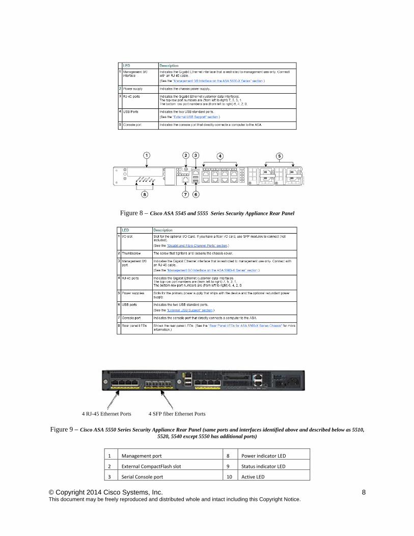
Figure 8 – Cisco ASA 5545 and 5555 Series Security Appliance Rear Panel
Figure 9 – Cisco ASA 5550 Series Security Appliance Rear Panel (same ports and interfaces identified above and described below as 5510, 5520, 5540 except 5550 has additional ports)
1 Management port 8 Power indicator LED
2 External CompactFlash slot 9 Status indicator LED
3 Serial Console port 10 Active LED
4 RJ-45 Ethernet Ports 4 SFP fiber Ethernet Ports
© Copyright 2014 Cisco Systems, Inc. 9 This document may be freely reproduced and distributed whole and intact including this Copyright Notice.
4 Power switch 11 VPN LED
5 Power indicator LED 12 Flash LED
6 USB 2.0 interfaces 13 Aux Port
7 Network interfaces 14 Power connector
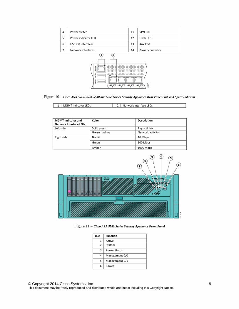
Figure 10 – Cisco ASA 5510, 5520, 5540 and 5550 Series Security Appliance Rear Panel Link and Speed Indicator
1 MGMT indicator LEDs 2 Network interface LEDs
MGMT indicator and Network interface LEDs
Color Description
Left side Solid green Physical link
Green flashing Network activity
Right side Not lit 10 Mbps
Green 100 Mbps
Amber 1000 Mbps
Figure 11 – Cisco ASA 5580 Series Security Appliance Front Panel
LED Function
1 Active
2 System
3 Power Status
4 Management 0/0
5 Management 0/1
6 Power
© Copyright 2014 Cisco Systems, Inc. 10 This document may be freely reproduced and distributed whole and intact including this Copyright Notice.
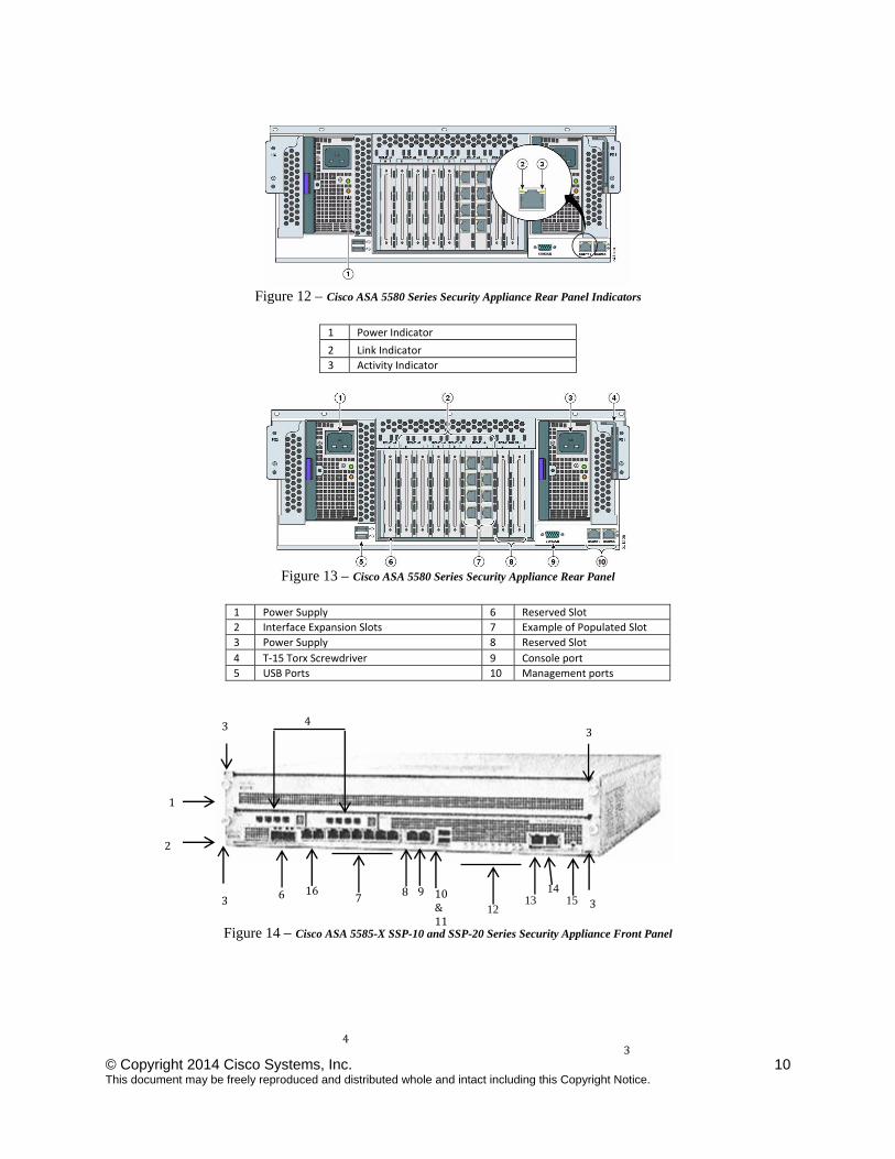
Figure 12 – Cisco ASA 5580 Series Security Appliance Rear Panel Indicators
1 Power Indicator
2 Link Indicator
3 Activity Indicator
Figure 13 – Cisco ASA 5580 Series Security Appliance Rear Panel
1 Power Supply 6 Reserved Slot
2 Interface Expansion Slots 7 Example of Populated Slot
3 Power Supply 8 Reserved Slot
4 T‐15 Torx Screwdriver 9 Console port
5 USB Ports 10 Management ports
Figure 14 – Cisco ASA 5585-X SSP-10 and SSP-20 Series Security Appliance Front Panel
3 4
3 3 4
3 3
1
2
6 7 8 10
&11
12
14 15
9 13
16
© Copyright 2014 Cisco Systems, Inc. 11 This document may be freely reproduced and distributed whole and intact including this Copyright Notice.
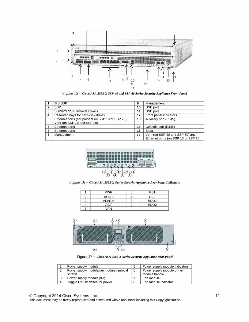
Figure 15 – Cisco ASA 5585-X SSP-40 and SSP-60 Series Security Appliance Front Panel
1 IPS SSP 9 Management2 SSP 10 USB port 3 SSP/IPS SSP removal screws 11 USB port 4 Reserved bays for hard-disk drives 12 Front panel indicators 5 Ethernet ports (not present on SSP 10 or SSP 20)
Vent (on SSP 10 and SSP 20) 13 Auxiliary port (RJ45)
6 Ethernet ports 14 Console port (RJ45) 7 Ethernet ports 15 Eject 8 Management 16 Vent (on SSP 40 and SSP 60) and
Ethernet ports (on SSP 10 or SSP 20)
Figure 16 – Cisco ASA 5585-X Series Security Appliance Rear Panel Indicators
1 PWR 6 PS1
2 BOOT 7 PS0 3 ALARM 8 HDD1 4 ACT 9 HDD2 5 VPN
Figure 17 – Cisco ASA 5585-X Series Security Appliance Rear Panel
1 Power supply module 5 Power supply module indicators 2 Power supply module/fan module removal
screws 6 Power supply module or fan
module handle 3 Power supply module plug 7 Fan module 4 Toggle On/Off switch for power 8 Fan module indicator
3
3 3
1
2
5 6 7 8 9 10
&11
12
14 15 13
© Copyright 2014 Cisco Systems, Inc. 12 This document may be freely reproduced and distributed whole and intact including this Copyright Notice.
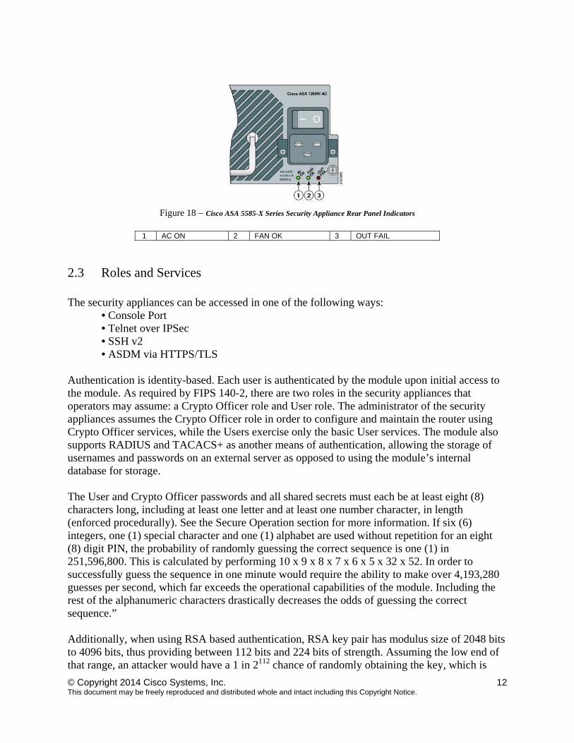
Figure 18 – Cisco ASA 5585-X Series Security Appliance Rear Panel Indicators
1 AC ON 2 FAN OK 3 OUT FAIL
2.3 Roles and Services The security appliances can be accessed in one of the following ways:
• Console Port • Telnet over IPSec • SSH v2 • ASDM via HTTPS/TLS
Authentication is identity-based. Each user is authenticated by the module upon initial access to the module. As required by FIPS 140-2, there are two roles in the security appliances that operators may assume: a Crypto Officer role and User role. The administrator of the security appliances assumes the Crypto Officer role in order to configure and maintain the router using Crypto Officer services, while the Users exercise only the basic User services. The module also supports RADIUS and TACACS+ as another means of authentication, allowing the storage of usernames and passwords on an external server as opposed to using the module’s internal database for storage. The User and Crypto Officer passwords and all shared secrets must each be at least eight (8) characters long, including at least one letter and at least one number character, in length (enforced procedurally). See the Secure Operation section for more information. If six (6) integers, one (1) special character and one (1) alphabet are used without repetition for an eight (8) digit PIN, the probability of randomly guessing the correct sequence is one (1) in 251,596,800. This is calculated by performing 10 x 9 x 8 x 7 x 6 x 5 x 32 x 52. In order to successfully guess the sequence in one minute would require the ability to make over 4,193,280 guesses per second, which far exceeds the operational capabilities of the module. Including the rest of the alphanumeric characters drastically decreases the odds of guessing the correct sequence.” Additionally, when using RSA based authentication, RSA key pair has modulus size of 2048 bits to 4096 bits, thus providing between 112 bits and 224 bits of strength. Assuming the low end of that range, an attacker would have a 1 in 2112 chance of randomly obtaining the key, which is
© Copyright 2014 Cisco Systems, Inc. 13 This document may be freely reproduced and distributed whole and intact including this Copyright Notice.
much stronger than the one in a million chance required by FIPS 140-2. To exceed a one in 100,000 probability of a successful random key guess in one minute, an attacker would have to be capable of approximately 1.8x10²¹ attempts per minute, which far exceeds the operational capabilities of the modules to support The User and Crypto Officer passwords and all shared secrets must each be at least eight (8) characters long, including at least one letter and at least one number character, in length (enforced procedurally).
User Services
Users can access the system in two ways:
1. By accessing the console port with a terminal program or via IPSec protected telnet or SSH session to an Ethernet ports port. The IOS prompts the User for username and password. If the password is correct, the User is allowed entry to the IOS executive program.
2. Via an IPSec session. This session is authenticated either using a shared secret or RSA digital signature authentication mechanism.
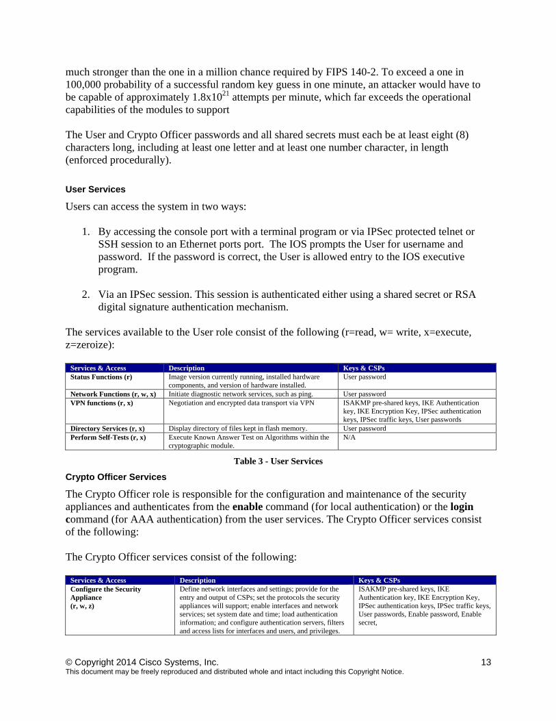
The services available to the User role consist of the following (r=read, w= write, x=execute, z=zeroize):
Services & Access Description Keys & CSPs Status Functions (r) Image version currently running, installed hardware
components, and version of hardware installed. User password
Network Functions (r, w, x) Initiate diagnostic network services, such as ping. User password VPN functions (r, x) Negotiation and encrypted data transport via VPN ISAKMP pre-shared keys, IKE Authentication
key, IKE Encryption Key, IPSec authentication keys, IPSec traffic keys, User passwords
Directory Services (r, x) Display directory of files kept in flash memory. User password Perform Self-Tests (r, x) Execute Known Answer Test on Algorithms within the
cryptographic module. N/A
Table 3 - User Services
Crypto Officer Services
The Crypto Officer role is responsible for the configuration and maintenance of the security appliances and authenticates from the enable command (for local authentication) or the login command (for AAA authentication) from the user services. The Crypto Officer services consist of the following: The Crypto Officer services consist of the following:
Services & Access Description Keys & CSPs Configure the Security Appliance (r, w, z)
Define network interfaces and settings; provide for the entry and output of CSPs; set the protocols the security appliances will support; enable interfaces and network services; set system date and time; load authentication information; and configure authentication servers, filters and access lists for interfaces and users, and privileges.
ISAKMP pre-shared keys, IKE Authentication key, IKE Encryption Key, IPSec authentication keys, IPSec traffic keys, User passwords, Enable password, Enable secret,
© Copyright 2014 Cisco Systems, Inc. 14 This document may be freely reproduced and distributed whole and intact including this Copyright Notice.
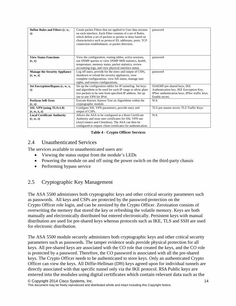
Define Rules and Filters (r, w, z)
Create packet Filters that are applied to User data streams on each interface. Each Filter consists of a set of Rules, which define a set of packets to permit or deny based on characteristics such as protocol ID, addresses, ports, TCP connection establishment, or packet direction.
password
View Status Functions (r, x)
View the configuration, routing tables, active sessions, use SNMP queries to view SNMP MIB statistics, health, temperature, memory status, packet statistics, review accounting logs, and view physical interface status.
password
Manage the Security Appliance (r, w, z)
Log off users, provide for the entry and output of CSPs, shutdown or reload the security appliances, view complete configurations, view full status, manage user rights, and restore configurations.
password
Set Encryption/Bypass (r, w, x, z)
Set up the configuration tables for IP tunneling. Set keys and algorithms to be used for each IP range or allow plain text packets to be sent from specified IP address. Set up site to site VPN for IPv6.
ISAKMP pre-shared keys, IKE Authentication key, IKE Encryption Key, IPSec authentication keys, IPSec traffic keys, Enable secret,
Perform Self-Tests (r, x)
Execute Known Answer Test on Algorithms within the cryptographic module.
N/A
SSL VPN (using TLSv1.0) (r, w, x, z)
Configure SSL VPN parameters, provide entry and output of CSPs.
TLS pre-master secret, TLS Traffic Keys
Local Certificate Authority (r, w, z)
Allows the ASA to be configured as a Root Certificate Authority and issue user certificates for SSL VPN use (AnyConnect and Clientless). The ASA can then be configured to require client certificates for authentication.
N/A
Table 4 - Crypto Officer Services
2.4 Unauthenticated Services The services available to unauthenticated users are:
Viewing the status output from the module’s LEDs Powering the module on and off using the power switch on the third-party chassis Performing bypass service
2.5 Cryptographic Key Management The ASA 5500 administers both cryptographic keys and other critical security parameters such as passwords. All keys and CSPs are protected by the password-protection on the Crypto Officer role login, and can be zeroized by the Crypto Officer. Zeroization consists of overwriting the memory that stored the key or refreshing the volatile memory. Keys are both manually and electronically distributed but entered electronically. Persistent keys with manual distribution are used for pre-shared keys whereas protocols such as IKE, TLS and SSH are used for electronic distribution. The ASA 5500 module securely administers both cryptographic keys and other critical security parameters such as passwords. The tamper evidence seals provide physical protection for all keys. All pre-shared keys are associated with the CO role that created the keys, and the CO role is protected by a password. Therefore, the CO password is associated with all the pre-shared keys. The Crypto Officer needs to be authenticated to store keys. Only an authenticated Crypto Officer can view the keys. All Diffie-Hellman (DH) keys agreed upon for individual tunnels are directly associated with that specific tunnel only via the IKE protocol. RSAPublickeysareenteredintothemodulesusingdigitalcertificateswhichcontainrelevantdatasuchasthe
© Copyright 2014 Cisco Systems, Inc. 15 This document may be freely reproduced and distributed whole and intact including this Copyright Notice.
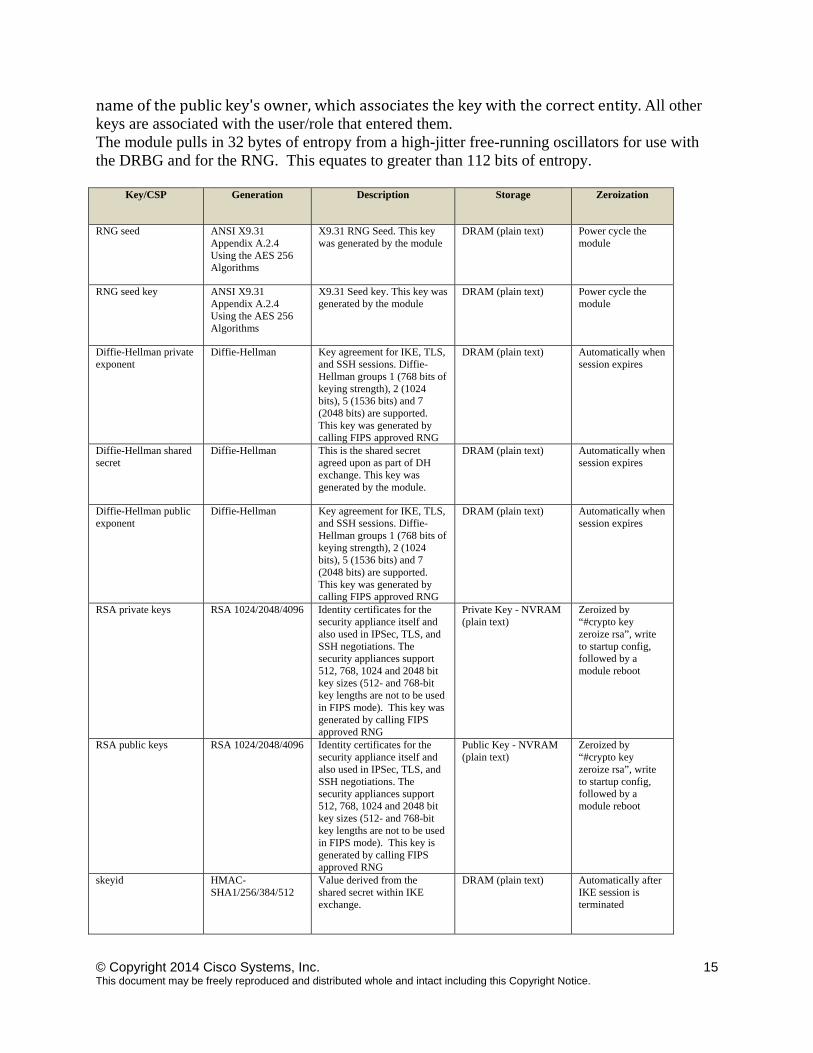
nameofthepublickey'sowner,whichassociatesthekeywiththecorrectentity.All other keys are associated with the user/role that entered them. The module pulls in 32 bytes of entropy from a high-jitter free-running oscillators for use with the DRBG and for the RNG. This equates to greater than 112 bits of entropy.
Key/CSP Generation Description Storage Zeroization
RNG seed ANSI X9.31 Appendix A.2.4 Using the AES 256 Algorithms
X9.31 RNG Seed. This key was generated by the module
DRAM (plain text) Power cycle the module
RNG seed key ANSI X9.31 Appendix A.2.4 Using the AES 256 Algorithms
X9.31 Seed key. This key was generated by the module
DRAM (plain text) Power cycle the module
Diffie-Hellman private exponent
Diffie-Hellman Key agreement for IKE, TLS, and SSH sessions. Diffie-Hellman groups 1 (768 bits of keying strength), 2 (1024 bits), 5 (1536 bits) and 7 (2048 bits) are supported. This key was generated by calling FIPS approved RNG
DRAM (plain text) Automatically when session expires
Diffie-Hellman shared secret
Diffie-Hellman This is the shared secret agreed upon as part of DH exchange. This key was generated by the module.
DRAM (plain text) Automatically when session expires
Diffie-Hellman public exponent
Diffie-Hellman Key agreement for IKE, TLS, and SSH sessions. Diffie-Hellman groups 1 (768 bits of keying strength), 2 (1024 bits), 5 (1536 bits) and 7 (2048 bits) are supported. This key was generated by calling FIPS approved RNG
DRAM (plain text) Automatically when session expires
RSA private keys RSA 1024/2048/4096 Identity certificates for the security appliance itself and also used in IPSec, TLS, and SSH negotiations. The security appliances support 512, 768, 1024 and 2048 bit key sizes (512- and 768-bit key lengths are not to be used in FIPS mode). This key was generated by calling FIPS approved RNG
Private Key - NVRAM (plain text)
Zeroized by “#crypto key zeroize rsa”, write to startup config, followed by a module reboot
RSA public keys RSA 1024/2048/4096 Identity certificates for the security appliance itself and also used in IPSec, TLS, and SSH negotiations. The security appliances support 512, 768, 1024 and 2048 bit key sizes (512- and 768-bit key lengths are not to be used in FIPS mode). This key is generated by calling FIPS approved RNG
Public Key - NVRAM (plain text)
Zeroized by “#crypto key zeroize rsa”, write to startup config, followed by a module reboot
skeyid HMAC-SHA1/256/384/512
Value derived from the shared secret within IKE exchange.
DRAM (plain text) Automatically after IKE session is terminated
© Copyright 2014 Cisco Systems, Inc. 16 This document may be freely reproduced and distributed whole and intact including this Copyright Notice.
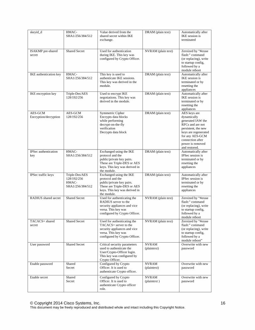
skeyid_d HMAC-SHA1/256/384/512
Value derived from the shared secret within IKE exchange.
DRAM (plain text) Automatically after IKE session is terminated
ISAKMP pre-shared secret
Shared Secret Used for authentication during IKE. This key was configured by Crypto Officer.
NVRAM (plain text) Zeroized by “#erase flash:” command (or replacing), write to startup config, followed by a module reboot
IKE authentication key HMAC-SHA1/256/384/512
This key is used to authenticate IKE sessions. This key was derived in the module.
DRAM (plain text) Automatically after IKE session is terminated or by resetting the appliances
IKE encryption key Triple-Des/AES 128/192/256
Used to encrypt IKE negotiations. This key was derived in the module.
DRAM (plain text) Automatically after IKE session is terminated or by resetting the appliances
AES-GCM Encryption/decryption
AES-GCM 128/192/256
Symmetric Cipher Encrypts data blocks while performing decrypt-on-the-fly verification Decrypts data block
DRAM (plain text) AES keys are dynamically generated IAW the RFCs and are not persistent, the new keys are regenerated for any AES-GCM connection after power is removed and restored.
IPSec authentication key
HMAC-SHA1/256/384/512
Exchanged using the IKE protocol and the public/private key pairs. These are Triple-DES or AES keys. This key was derived in the module.
DRAM (plain text) Automatically after IPSec session is terminated or by resetting the appliances
IPSec traffic keys Triple-Des/AES 128/192/256 HMAC-SHA1/256/384/512
Exchanged using the IKE protocol and the public/private key pairs. These are Triple-DES or AES keys. This key was derived in the module.
DRAM (plain text) Automatically after IPSec session is terminated or by resetting the appliances
RADIUS shared secret Shared Secret Used for authenticating the RADIUS server to the security appliances and vice versa. This key was configured by Crypto Officer.
NVRAM (plain text) Zeroized by “#erase flash:” command (or replacing), write to startup config, followed by a module reboot
TACACS+ shared secret
Shared Secret Used for authenticating the TACACS+ server to the security appliances and vice versa. This key was configured by Crypto Officer.
NVRAM (plain text) Zeroized by “#erase flash:” command (or replacing), write to startup config, followed by a module reboot”
User password Shared Secret Critical security parameters used to authenticate the User/Crypto-Officer login. This key was configured by Crypto Officer.
NVRAM (plaintext)
Overwrite with new password
Enable password Shared Secret
Configured by Crypto Officer. It is used to authenticate Crypto officer.
NVRAM (plaintext)
Overwrite with new password
Enable secret Shared Secret
Configured by Crypto Officer. It is used to authenticate Crypto officer role.
NVRAM (plaintext )
Overwrite with new password

© Copyright 2014 Cisco Systems, Inc. 17 This document may be freely reproduced and distributed whole and intact including this Copyright Notice.
TLS pre-master secret Shared Secret Shared secret created/derived using asymmetric cryptography from which new HTTPS session keys can be created. This key entered into the module in cipher text form, encrypted by RSA public key.
DRAM (plaintext)
Automatically when TLS session is terminated.
TLS traffic keys Triple-DES/AES 128/192/256 HMAC-SHA1/256/384/512
Used in HTTPS connections. Generated using TLS protocol. This key was derived in the module.
DRAM (plain text) Automatically when TLS session is terminated
SSH v2 authentication keys
HMAC-SHA1/256/384/512
This key is used to perform the authentication between the SSH client and SSH server. This key was derived in the module.
DRAM (plain text) Zeroized automatically when SSH session is closed
SSH v2 session encryption keys
Triple-Des/AES 128/192/256
This is the symmetric SSH key used to protect SSH session. This key was derived in the module.
DRAM (plain text) Zeroized automatically when SSH session is closed
ECDSA private key ECDSA P-256,384,521
Key pair generation, signature generation/ verification
DRAM Zeroized upon API call “#crypto key zeroize ecdsa”
ECDSA public key ECDSA P-256,384,521
Key pair generation, signature generation/ verification
DRAM Zeroized upon API call “#crypto key zeroize ecdsa”
DRBG Seed SHA-512 Hash DRBG
This is the internal value generated by the module and used in the DRBG
DRAM Power cycle the module
DRBG V value SHA-512 Hash DRBG
This is the internal value generated by the module and used in the DRBG
DRAM Power cycle the module
DRBG C value SHA-512 Hash DRBG
This is the internal value generated by the module and used in the DRBG
DRAM Power cycle the module
Table 5 Cryptographic Keys and CSPs
2.6 Cryptographic Algorithms
The module implements a variety of approved and non-approved algorithms.
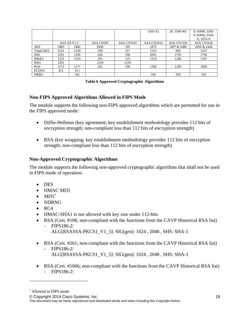
Approved Cryptographic Algorithms
The routers support the following FIPS-2 approved algorithm implementations:
Algorithm Algorithm Certificate Number ASA OS (Firmware) ASA On-board
(Cavium Nitrox Lite)
(ASA 5505)
ASA On-board (Cavium Nitrox
Lite) (ASA 5510, 5520, 5540, 5550)
ASA On-board (Cavium Nitrox
PX) (ASA 5512-X, 5515-
X, 5525-X,
ASA On-board
(Cavium Nitrox PX) (ASA 5580-
ASA On-board (Cavium Nitrox PX) (ASA 5585-X SSP10, 5585-X SSP20, 5585-
© Copyright 2014 Cisco Systems, Inc. 18 This document may be freely reproduced and distributed whole and intact including this Copyright Notice.
Table 6 Approved Cryptographic Algorithms
Non-FIPS Approved Algorithms Allowed in FIPS Mode
The module supports the following non-FIPS approved algorithms which are permitted for use in the FIPS approved mode:
Diffie-Hellman (key agreement; key establishment methodology provides 112 bits of encryption strength; non-compliant less than 112 bits of encryption strength)
RSA (key wrapping; key establishment methodology provides 112 bits of encryption strength; non-compliant less than 112 bits of encryption strength)
Non-Approved Cryptographic Algorithms
The module supports the following non-approved cryptographic algorithms that shall not be used in FIPS mode of operation:
DES HMAC MD5 MD51 NDRNG RC4 HMAC-SHA1 is not allowed with key size under 112-bits RSA (Cert. #106; non-compliant with the functions from the CAVP Historical RSA list)
- FIPS186-2: ALG[RSASSA-PKCS1_V1_5]: SIG(gen): 1024 , 2048 , SHS: SHA-1
RSA (Cert. #261; non-compliant with the functions from the CAVP Historical RSA list)
- FIPS186-2: ALG[RSASSA-PKCS1_V1_5]: SIG(gen): 1024 , 2048 , SHS: SHA-1
RSA (Cert. #1066; non-compliant with the functions from the CAVP Historical RSA list)
- FIPS186-2:
1 Allowed in FIPS mode
5545-X) 20, 5580-40) X SSP40, 5585-X SSP60, 5545-
X, 5555-X ASA OS 9.1.2 ASA CN505 ASA CN1010 ASA CN1610 ASA CN1520 ASA CN1620 AES 2483 2482 2049 105 2472 1407 & 2480 2050 & 2444 Triple-DES 1521 1520 559 217 1513 960 1321 SHS 2101 2100 630 196 2091 1793 1794 HMAC 1525 1524 301 125 1514 1246 1247 RNG 1201 1210 1210 RSA 1272 1271 261 106 1260 1269 1066 ECDSA 412 411 DRBG 341 336 339 332
© Copyright 2014 Cisco Systems, Inc. 19 This document may be freely reproduced and distributed whole and intact including this Copyright Notice.
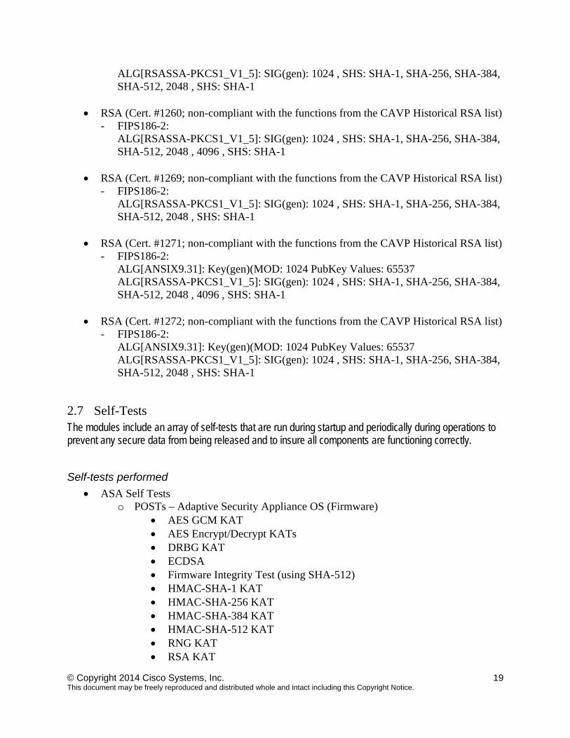
ALG[RSASSA-PKCS1_V1_5]: SIG(gen): 1024 , SHS: SHA-1, SHA-256, SHA-384, SHA-512, 2048 , SHS: SHA-1
RSA (Cert. #1260; non-compliant with the functions from the CAVP Historical RSA list)
- FIPS186-2: ALG[RSASSA-PKCS1_V1_5]: SIG(gen): 1024 , SHS: SHA-1, SHA-256, SHA-384, SHA-512, 2048 , 4096 , SHS: SHA-1
RSA (Cert. #1269; non-compliant with the functions from the CAVP Historical RSA list)
- FIPS186-2: ALG[RSASSA-PKCS1_V1_5]: SIG(gen): 1024 , SHS: SHA-1, SHA-256, SHA-384, SHA-512, 2048 , SHS: SHA-1
RSA (Cert. #1271; non-compliant with the functions from the CAVP Historical RSA list)
- FIPS186-2: ALG[ANSIX9.31]: Key(gen)(MOD: 1024 PubKey Values: 65537 ALG[RSASSA-PKCS1_V1_5]: SIG(gen): 1024 , SHS: SHA-1, SHA-256, SHA-384, SHA-512, 2048 , 4096 , SHS: SHA-1
RSA (Cert. #1272; non-compliant with the functions from the CAVP Historical RSA list)
- FIPS186-2: ALG[ANSIX9.31]: Key(gen)(MOD: 1024 PubKey Values: 65537 ALG[RSASSA-PKCS1_V1_5]: SIG(gen): 1024 , SHS: SHA-1, SHA-256, SHA-384, SHA-512, 2048 , SHS: SHA-1
2.7 Self-Tests The modules include an array of self-tests that are run during startup and periodically during operations to prevent any secure data from being released and to insure all components are functioning correctly.
Self-tests performed
ASA Self Tests o POSTs – Adaptive Security Appliance OS (Firmware)
AES GCM KAT AES Encrypt/Decrypt KATs DRBG KAT ECDSA Firmware Integrity Test (using SHA-512) HMAC-SHA-1 KAT HMAC-SHA-256 KAT HMAC-SHA-384 KAT HMAC-SHA-512 KAT RNG KAT RSA KAT
© Copyright 2014 Cisco Systems, Inc. 20 This document may be freely reproduced and distributed whole and intact including this Copyright Notice.
SHA-1 KAT SHA-256 KAT SHA–384 KAT SHA-512 KAT Triple-DES Encrypt/Decrypt KATs
o POSTs – ASA On-board (Hardware)
AES Encrypt/Decrypt KATs DRBG KAT HMAC-SHA-1 KAT HMAC-SHA-256 KAT (5580 and 5585 models only) HMAC-SHA-384 KAT (5580 and 5585 models only) HMAC-SHA-512 KAT (5580 and 5585 models only) RNG KAT RSA KAT SHA-1 KAT SHA-256 KAT (5580 and 5585 models only) SHA-384 KAT (5580 and 5585 models only) SHA-512 KAT (5580 and 5585 models only) Triple-DES Encrypt/Decrypt KATs
o Conditional tests - Adaptive Security Appliance OS (Firmware)
RSA pairwise consistency test (encrypt/decrypt and sign/verify) ECDSA pairwise consistency test Conditional Bypass test Continuous random number generation test for FIPS approved and non-
approved RNGs
o Conditional tests - ASA On-board (Hardware) RSA pairwise consistency test (encrypt/decrypt and sign/verify) Continuous random number generation test for FIPS approved RNG
The security appliances perform all power-on self-tests automatically at boot when FIPS mode is enabled. All power-on self-tests must be passed before a User/Crypto Officer can perform services. The power-on self-tests are performed after the cryptographic systems are initialized but prior to the initialization of the LAN’s interfaces; this prevents the security appliances from passing any data during a power-on self-test failure. In the unlikely event that a power-on self-test fails, an error message is displayed on the console followed by a security appliance reboot.
2.8 Physical Security The FIPS 140-2 level 2 physical security requirements for the modules are met by the use of opacity shields covering the front panels of modules to provide the required opacity and tamper evident seals to provide the required tamper evidence. The following sections illustrate the physical security provided by the module.
© Copyright 2014 Cisco Systems, Inc. 21 This document may be freely reproduced and distributed whole and intact including this Copyright Notice.
The following table shows the tamper labels and opacity shields that shall be installed on the modules to operate in a FIPS approved mode of operation. The CO is responsible for using, securing and having control at all times of any unused tamper evident labels. Actions to be taken when any evidence of tampering should be addressed within site security program.
Model Number Tamper labels
Tamper Evident Labels Number Opacity Shields
Opacity Shields
5505 2 DS-FIPS-KIT= Rev –BO 1 ASA5505-FIPS-KIT Rev–A0 5510-5550 4 DS-FIPS-KIT= Rev –BO 0 None 5512-X,5515-X,5525-X,5545-X, 5555-X
3 DS-FIPS-KIT= Rev –BO 0 None
5580 17 ASA5580-FIPS-KIT 2 ASA5580-FIPS-KIT 5585-X 8 ASA5585-X-FIPS-KIT 1 ASA5585-X-FIPS-KIT
Table 7 – Tamper/Opacity
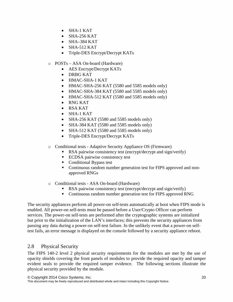
ASA 5505 Opacity Shield
To install an opacity shield on the ASA 5505, follow these steps: Step 1: Remove the three screws from the bottom of the Cisco ASA 5505
Step 2: Slide the ASA 5505 into the FIPS enclosure Step 3: Turn the FIPS enclosure with the chassis securely inside and use the three screws you
removed in Step 1 to screw the FIPS enclosure to the Cisco ASA 5505. Step 4: Apply the tamper evident label over the screw on the bottom. Please see Figure 24 for
placement of the TEL.
Step 5: Apply another tamper evident label should be placed so that the one half of the tamper evident label covers the enclosure and the other half covers the Cisco ASA 5505 chassis. Please see Figure 23 for placement of the TEL.
Figure 19 – ASA 5505 Opacity Shield Placement
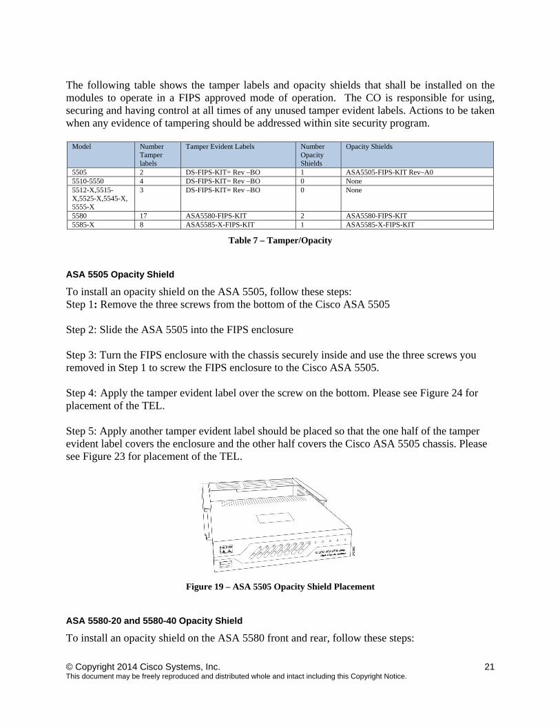
ASA 5580-20 and 5580-40 Opacity Shield
To install an opacity shield on the ASA 5580 front and rear, follow these steps:
© Copyright 2014 Cisco Systems, Inc. 22 This document may be freely reproduced and distributed whole and intact including this Copyright Notice.
Step 1: Power off the ASA.
Step 2: Copy the ASA 5580 serial number on a label and stick it on the chassis where it can be retrieved easily for future use,
Step 3: Release the latches on the lever
Step 4: Lower the handle, and pull the module out of the ASA until the release latches catch.
Step 5: Remove the five screws from the top and four screws on the sides of the front shield assembly. Keep the screws in a secure place for later use.
Step 6: Clean the chassis of any grease, dirt or oil with alcohol where the self-adhesive tape will stick on the chassis. Step 7: Place the front surround panel over the front of the module so that the roller balls on the top of the module are visible through the matching openings on the surround panel
Step 8: Remove the tape backing from the self-adhesive tape.
Step 9: Press down the self-adhesive tape to make sure the front surround panel is firmly stuck to the chassis.
Step 10: Push the module back into the chassis and use the handle to lock the module into place Step 11: Install the front panel inside the front surround panel and secure it with the nine screws you removed in Step 5.
Figure 20 – ASA 5580 Front Opacity Shield Placement
© Copyright 2014 Cisco Systems, Inc. 23 This document may be freely reproduced and distributed whole and intact including this Copyright Notice.
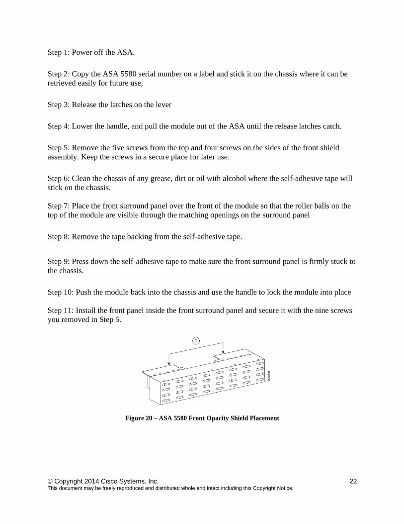
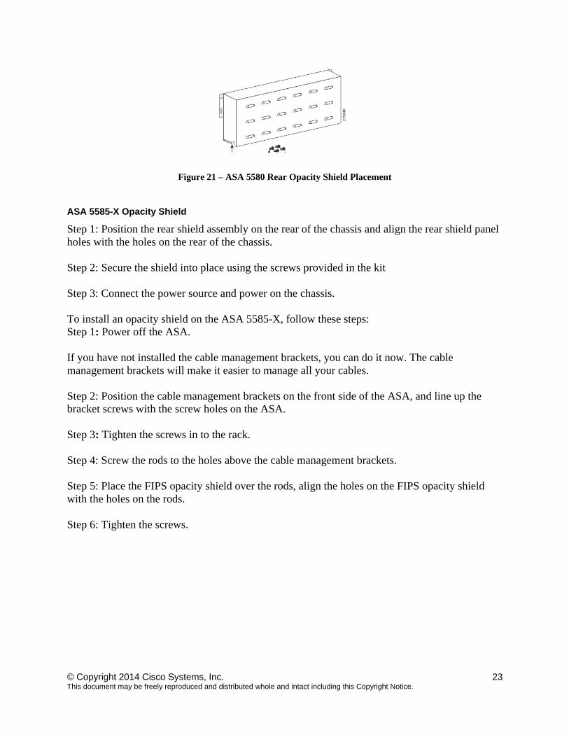
Figure 21 – ASA 5580 Rear Opacity Shield Placement
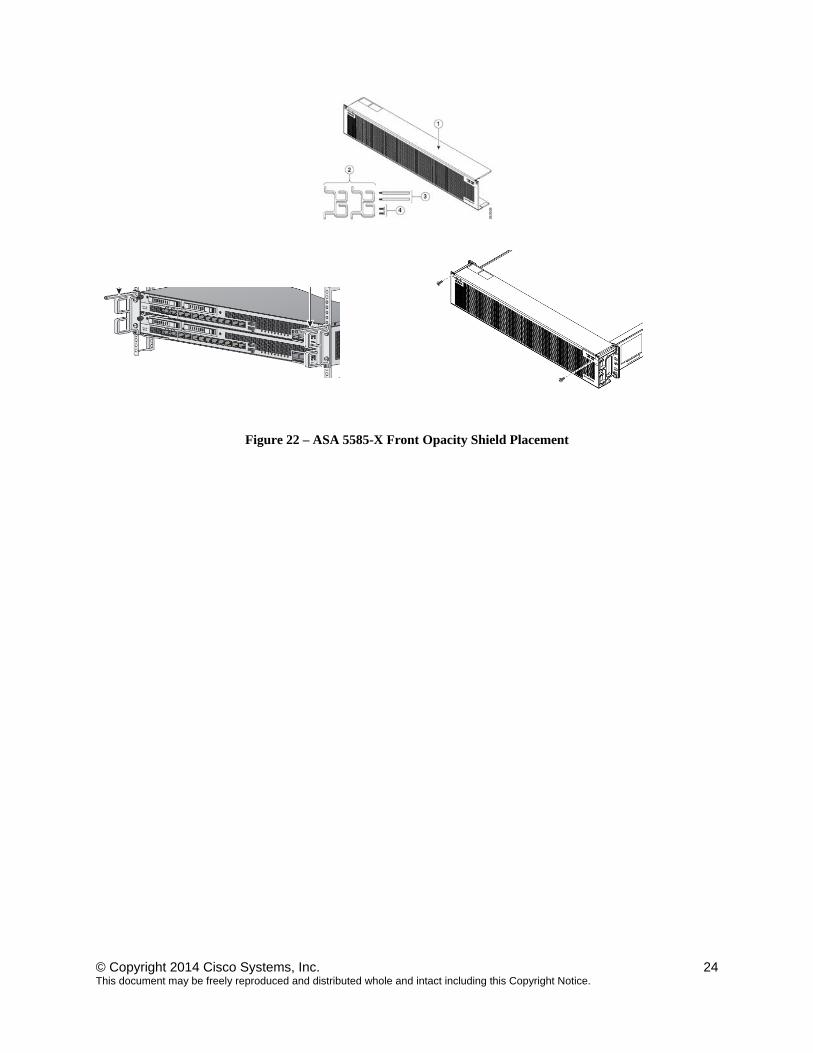
ASA 5585-X Opacity Shield
Step 1: Position the rear shield assembly on the rear of the chassis and align the rear shield panel holes with the holes on the rear of the chassis. Step 2: Secure the shield into place using the screws provided in the kit Step 3: Connect the power source and power on the chassis. To install an opacity shield on the ASA 5585-X, follow these steps: Step 1: Power off the ASA. If you have not installed the cable management brackets, you can do it now. The cable management brackets will make it easier to manage all your cables. Step 2: Position the cable management brackets on the front side of the ASA, and line up the bracket screws with the screw holes on the ASA. Step 3: Tighten the screws in to the rack. Step 4: Screw the rods to the holes above the cable management brackets. Step 5: Place the FIPS opacity shield over the rods, align the holes on the FIPS opacity shield with the holes on the rods. Step 6: Tighten the screws.
© Copyright 2014 Cisco Systems, Inc. 24 This document may be freely reproduced and distributed whole and intact including this Copyright Notice.
Figure 22 – ASA 5585-X Front Opacity Shield Placement

© Copyright 2014 Cisco Systems, Inc. 25 This document may be freely reproduced and distributed whole and intact including this Copyright Notice.
Tamper Evidence Labels (TELs) Once the module has been configured to meet overall FIPS 140-2 Level 2 requirements, the module cannot be accessed without signs of tampering. The CO shall inspect for signs of tampering periodically. To seal the system, apply tamper-evidence labels as depicted in the figures below.
ASA 5505
Apply the two tamper evident labels as follows:
Figure 23 Cisco ASA 5505 Security Appliance Tamper Evident Label Placement
Figure 24 Cisco ASA 5505 Security Appliance Tamper Evident Label Placement, bottom view
TEL 1
TEL 2
© Copyright 2014 Cisco Systems, Inc. 26 This document may be freely reproduced and distributed whole and intact including this Copyright Notice.
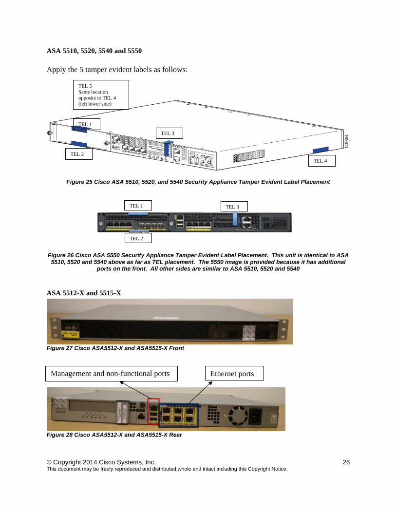
ASA 5510, 5520, 5540 and 5550
Apply the 5 tamper evident labels as follows:
Figure 25 Cisco ASA 5510, 5520, and 5540 Security Appliance Tamper Evident Label Placement
Figure 26 Cisco ASA 5550 Security Appliance Tamper Evident Label Placement. This unit is identical to ASA 5510, 5520 and 5540 above as far as TEL placement. The 5550 image is provided because it has additional
ports on the front. All other sides are similar to ASA 5510, 5520 and 5540
ASA 5512-X and 5515-X
Figure 27 Cisco ASA5512-X and ASA5515-X Front
Figure 28 Cisco ASA5512-X and ASA5515-X Rear
TEL 1
TEL 2
TEL 3
TEL 4
TEL 1 TEL 3
TEL 2
TEL 5 Same location opposite to TEL 4 (left lower side)
Ethernet ports Management and non-functional ports
© Copyright 2014 Cisco Systems, Inc. 27 This document may be freely reproduced and distributed whole and intact including this Copyright Notice.
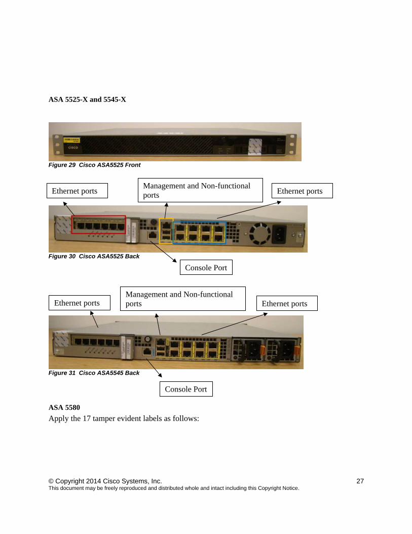
ASA 5525-X and 5545-X
Figure 29 Cisco ASA5525 Front
Figure 30 Cisco ASA5525 Back
v
Figure 31 Cisco ASA5545 Back
ASA 5580
Apply the 17 tamper evident labels as follows:
Ethernet ports Management and Non-functional ports Ethernet ports
Console Port
Ethernet ports Management and Non-functional ports Ethernet ports
Console Port

© Copyright 2014 Cisco Systems, Inc. 28 This document may be freely reproduced and distributed whole and intact including this Copyright Notice.
Figure 32 Cisco ASA 5580 Security Appliance Tamper Evident Label Placement (Front Face)
Figure 33 Cisco ASA 5580 Security Appliance Tamper Evident Label Placement (Back Face)
Figure 34 Cisco ASA 5580 Security Appliance Tamper Evident Label Placement (Side Face)
Figure 35 Cisco ASA 5580 Security Appliance Tamper Evident Label Placement (Side Face)
TEL 1 2 3 4 TEL 5
TEL 6 TEL 7
TEL 8 TEL 11TEL 9 TEL 10
TEL 14
TEL 12
TEL 16
TEL 13
TEL 12 TEL 17
TEL 15
TEL 13
© Copyright 2014 Cisco Systems, Inc. 29 This document may be freely reproduced and distributed whole and intact including this Copyright Notice.
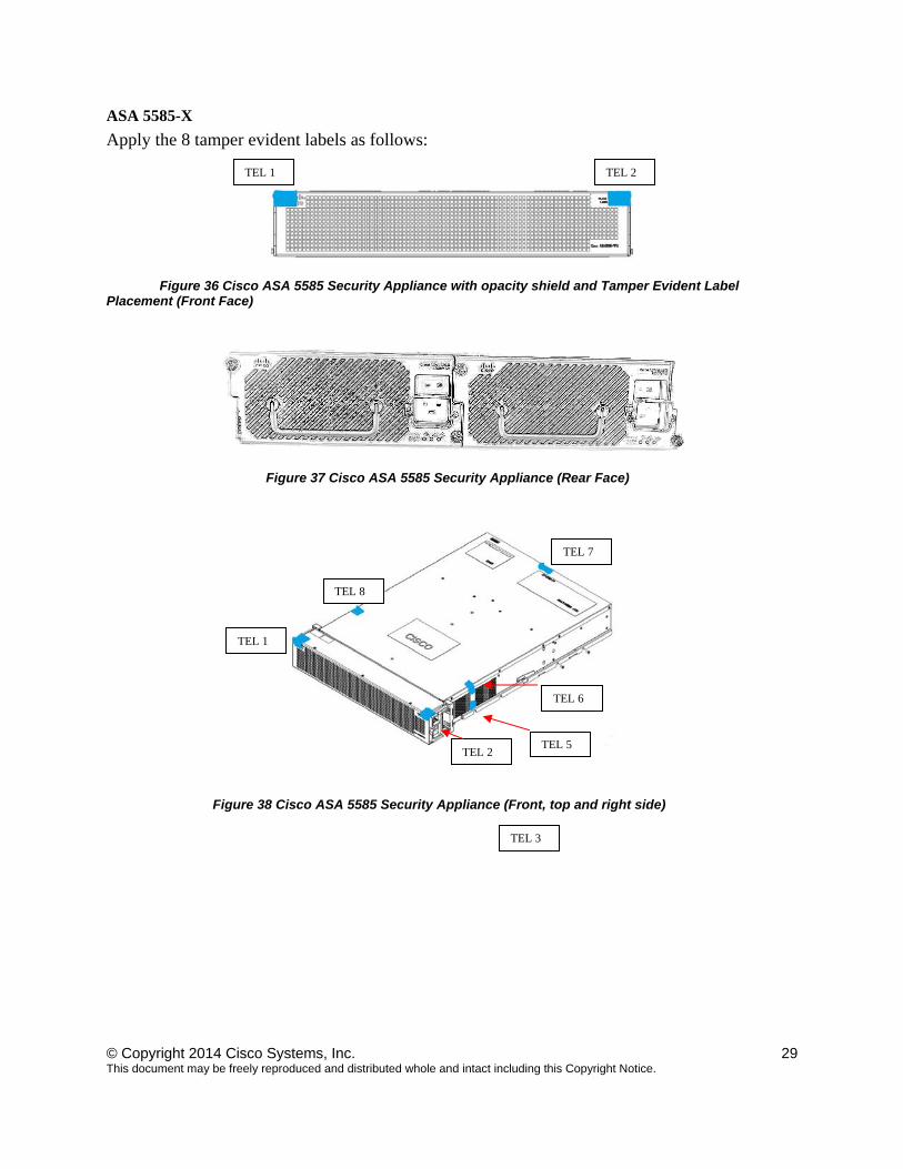
ASA 5585-X
Apply the 8 tamper evident labels as follows:
Figure 36 Cisco ASA 5585 Security Appliance with opacity shield and Tamper Evident Label Placement (Front Face)
Figure 37 Cisco ASA 5585 Security Appliance (Rear Face)
Figure 38 Cisco ASA 5585 Security Appliance (Front, top and right side)
TEL 1 TEL 2
TEL 3
TEL 6
TEL 7
TEL 8
TEL 1
TEL 2TEL 5
© Copyright 2014 Cisco Systems, Inc. 30 This document may be freely reproduced and distributed whole and intact including this Copyright Notice.
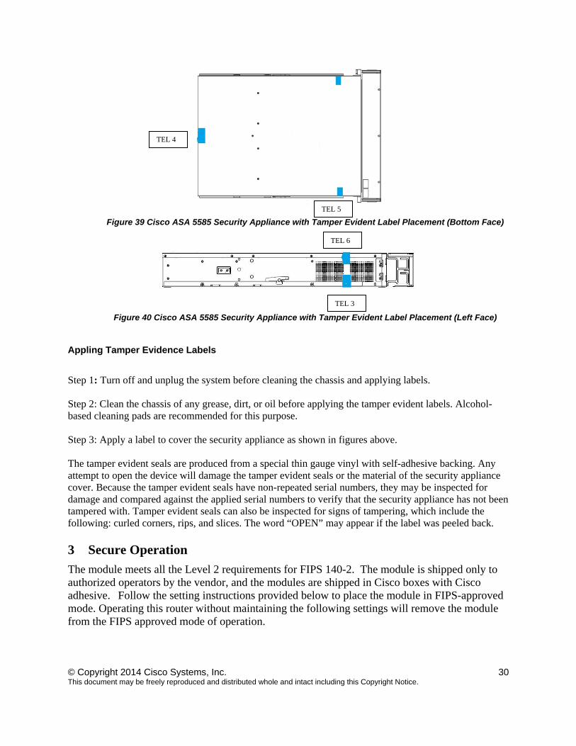
Figure 39 Cisco ASA 5585 Security Appliance with Tamper Evident Label Placement (Bottom Face)
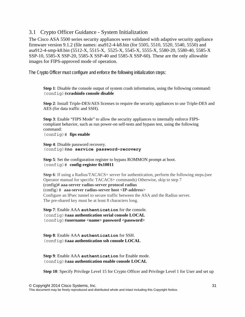
Figure 40 Cisco ASA 5585 Security Appliance with Tamper Evident Label Placement (Left Face)
Appling Tamper Evidence Labels
Step 1: Turn off and unplug the system before cleaning the chassis and applying labels. Step 2: Clean the chassis of any grease, dirt, or oil before applying the tamper evident labels. Alcohol-based cleaning pads are recommended for this purpose. Step 3: Apply a label to cover the security appliance as shown in figures above. The tamper evident seals are produced from a special thin gauge vinyl with self-adhesive backing. Any attempt to open the device will damage the tamper evident seals or the material of the security appliance cover. Because the tamper evident seals have non-repeated serial numbers, they may be inspected for damage and compared against the applied serial numbers to verify that the security appliance has not been tampered with. Tamper evident seals can also be inspected for signs of tampering, which include the following: curled corners, rips, and slices. The word “OPEN” may appear if the label was peeled back. 3 Secure Operation
The module meets all the Level 2 requirements for FIPS 140-2. The module is shipped only to authorized operators by the vendor, and the modules are shipped in Cisco boxes with Cisco adhesive. Follow the setting instructions provided below to place the module in FIPS-approved mode. Operating this router without maintaining the following settings will remove the module from the FIPS approved mode of operation.
TEL 4
TEL 5
TEL 6
TEL 3
© Copyright 2014 Cisco Systems, Inc. 31 This document may be freely reproduced and distributed whole and intact including this Copyright Notice.
3.1 Crypto Officer Guidance - System Initialization The Cisco ASA 5500 series security appliances were validated with adaptive security appliance firmware version 9.1.2 (file names: asa912-4-k8.bin (for 5505, 5510, 5520, 5540, 5550) and asa912-4-smp-k8.bin (5512-X, 5515-X, 5525-X, 5545-X, 5555-X, 5580-20, 5580-40, 5585-X SSP-10, 5585-X SSP-20, 5585-X SSP-40 and 5585-X SSP-60). These are the only allowable images for FIPS-approved mode of operation. The Crypto Officer must configure and enforce the following initialization steps:
Step 1: Disable the console output of system crash information, using the following command: (config)#crashinfo console disable Step 2: Install Triple-DES/AES licenses to require the security appliances to use Triple-DES and AES (for data traffic and SSH). Step 3: Enable “FIPS Mode” to allow the security appliances to internally enforce FIPS-compliant behavior, such as run power-on self-tests and bypass test, using the following command: (config)# fips enable Step 4: Disable password recovery. (config)#no service password-recovery Step 5: Set the configuration register to bypass ROMMON prompt at boot. (config)# config-register 0x10011 Step 6: If using a Radius/TACACS+ server for authentication, perform the following steps.(see Operator manual for specific TACACS+ commands) Otherwise, skip to step 7 (config)# aaa-server radius-server protocol radius (config)# aaa-server radius-server host <IP-address> Configure an IPsec tunnel to secure traffic between the ASA and the Radius server. The pre-shared key must be at least 8 characters long. Step 7: Enable AAA authentication for the console. (config)#aaa authentication serial console LOCAL (config)#username <name> password <password> Step 8: Enable AAA authentication for SSH. (config)#aaa authentication ssh console LOCAL Step 9: Enable AAA authentication for Enable mode. (config)#aaa authentication enable console LOCAL Step 10: Specify Privilege Level 15 for Crypto Officer and Privilege Level 1 for User and set up
© Copyright 2014 Cisco Systems, Inc. 32 This document may be freely reproduced and distributed whole and intact including this Copyright Notice.
username/password for each role. (config)#username <name> password <password> privilege 15 (config)#username <name> password <password> privilege 1 Step 11: Ensure passwords are at least 8 characters long. Step 12: All default passwords, such as enable and telnet, must be replaced with new passwords. Step 13: Apply tamper evident labels as described in the “Physical Security” section on page 17. Step 14: Reboot the security appliances.
3.2 Crypto Officer Guidance - System Configuration To operate in FIPS mode, the Crypto Officer must perform the following steps:
Step 1: Assign users a Privilege Level of 1. Step 2: Define RADIUS and TACACS+ shared secret keys that are at least 8 characters long and secure traffic between the security appliances and the RADIUS/TACACS+ server via IPSec tunnel. Note: Perform this step only if RADIUS/TACAS+ is configured, otherwise proceed to step 3. Step 3: Configure the TLS protocol when using HTTPS to protect administrative functions. Due to known issues relating to the use of TLS with certain versions of the Java plugin, we require that you upgrade to JRE 1.5.0_05 or later. The following configuration settings are known to work when launching ASDM in a TLS-only environment with JRE 1.5.0_05:
a. Configure the device to allow only TLSv1 packets using the following command: (config)# ssl server-version tlsv1-only (config)# ssl client-version tlsv1-only b. Uncheck SSL Version 2.0 in both the web browser and JRE security settings. c. Check TLS V1.0 in both the web browser and JRE security settings.
Step 4: Configure the security appliances to use SSHv2. Note that all operators must still authenticate after remote access is granted. (config)# ssh version 2 Step 5: Configure the security appliances such that any remote connections via Telnet are secured through IPSec. Step 6: Configure the security appliances such that only FIPS-approved algorithms are used for IPSec tunnels. Step 7: Configure the security appliances such that error messages can only be viewed by Crypto Officer.
© Copyright 2014 Cisco Systems, Inc. 33 This document may be freely reproduced and distributed whole and intact including this Copyright Notice.
Step 8: Configure SNMP to always use a secure IPSec tunnel. Step 9: Disable the TFTP server. Step 10: Disable HTTP for performing system management in FIPS mode of operation. HTTPS with TLS should always be used for Web-based management. Step 11: Ensure that installed digital certificates are signed using FIPS approved algorithms. Step 12: Ensure that the 512-bit and 768-bit RSA keys are not used. Step 13: Ensure that DH Group 1 (768-bits) keys are not used.
3.3 Identifying Router Operation in an Approved Mode The following activities are required to verify that that the module is operating in an Approved mode of operation.
1. Verify that the tamper evidence labels and FIPS opacity shields have been properly placed on the module based on the instructions specified in the “Physical Security” and “Secure Operation” sections of this document.
2. Verify that the length of User and Crypto Officer passwords and all shared secrets are at least eight (8) characters long, include at least one letter, and include at least one number character, as specified in the “Secure Operation” section of this document.
3. Issue the following commands: 'show crypto IPSec sa' and 'show crypto isakmp policy' to verify that only FIPS approved algorithms are used.
© Copyright 2014 Cisco Systems, Inc. 34 This document may be freely reproduced and distributed whole and intact including this Copyright Notice.
By printing or making a copy of this document, the user agrees to use this information for product evaluation purposes only. Sale of this information in whole or in part is not authorized by Cisco Systems.