Cisco Application Visibility and Control Solution Guide for … · CHAPTER 4 AVC Configuration 4-1...
76
Americas Headquarters Cisco Systems, Inc. 170 West Tasman Drive San Jose, CA 95134-1706 USA http://www.cisco.com Tel: 408 526-4000 800 553-NETS (6387) Fax: 408 527-0883 Cisco Application Visibility and Control Solution Guide for IOS XE Release 3.9S Originally posted: March 29, 2013 Revised: August 15, 2013 Text Part Number: OL-29170-03
-
Upload
trannguyet -
Category
Documents
-
view
220 -
download
0
Transcript of Cisco Application Visibility and Control Solution Guide for … · CHAPTER 4 AVC Configuration 4-1...

Cisco Application Visibility and Control Solution Guide for IOS XE Release 3.9S Originally posted: March 29, 2013 Revised: August 15, 2013
Americas HeadquartersCisco Systems, Inc.170 West Tasman DriveSan Jose, CA 95134-1706 USAhttp://www.cisco.comTel: 408 526-4000
800 553-NETS (6387)Fax: 408 527-0883
Text Part Number: OL-29170-03

THE SPECIFICATIONS AND INFORMATION REGARDING THE PRODUCTS IN THIS MANUAL ARE SUBJECT TO CHANGE WITHOUT NOTICE. ALL STATEMENTS, INFORMATION, AND RECOMMENDATIONS IN THIS MANUAL ARE BELIEVED TO BE ACCURATE BUT ARE PRESENTED WITHOUT WARRANTY OF ANY KIND, EXPRESS OR IMPLIED. USERS MUST TAKE FULL RESPONSIBILITY FOR THEIR APPLICATION OF ANY PRODUCTS.
THE SOFTWARE LICENSE AND LIMITED WARRANTY FOR THE ACCOMPANYING PRODUCT ARE SET FORTH IN THE INFORMATION PACKET THAT SHIPPED WITH THE PRODUCT AND ARE INCORPORATED HEREIN BY THIS REFERENCE. IF YOU ARE UNABLE TO LOCATE THE SOFTWARE LICENSE OR LIMITED WARRANTY, CONTACT YOUR CISCO REPRESENTATIVE FOR A COPY.
The Cisco implementation of TCP header compression is an adaptation of a program developed by the University of California, Berkeley (UCB) as part of UCB’s public domain version of the UNIX operating system. All rights reserved. Copyright © 1981, Regents of the University of California.
NOTWITHSTANDING ANY OTHER WARRANTY HEREIN, ALL DOCUMENT FILES AND SOFTWARE OF THESE SUPPLIERS ARE PROVIDED “AS IS” WITH ALL FAULTS. CISCO AND THE ABOVE-NAMED SUPPLIERS DISCLAIM ALL WARRANTIES, EXPRESSED OR IMPLIED, INCLUDING, WITHOUT LIMITATION, THOSE OF MERCHANTABILITY, FITNESS FOR A PARTICULAR PURPOSE AND NONINFRINGEMENT OR ARISING FROM A COURSE OF DEALING, USAGE, OR TRADE PRACTICE.
IN NO EVENT SHALL CISCO OR ITS SUPPLIERS BE LIABLE FOR ANY INDIRECT, SPECIAL, CONSEQUENTIAL, OR INCIDENTAL DAMAGES, INCLUDING, WITHOUT LIMITATION, LOST PROFITS OR LOSS OR DAMAGE TO DATA ARISING OUT OF THE USE OR INABILITY TO USE THIS MANUAL, EVEN IF CISCO OR ITS SUPPLIERS HAVE BEEN ADVISED OF THE POSSIBILITY OF SUCH DAMAGES.
Cisco and the Cisco logo are trademarks or registered trademarks of Cisco and/or its affiliates in the U.S. and other countries. To view a list of Cisco trademarks, go to this URL: www.cisco.com/go/trademarks. Third-party trademarks mentioned are the property of their respective owners. The use of the word partner does not imply a partnership relationship between Cisco and any other company. (1110R)
Any Internet Protocol (IP) addresses and phone numbers used in this document are not intended to be actual addresses and phone numbers. Any examples, command display output, network topology diagrams, and other figures included in the document are shown for illustrative purposes only. Any use of actual IP addresses or phone numbers in illustrative content is unintentional and coincidental.
Cisco Application Visibility and Control Solution Guide for IOS XE Release 3.9S © 2013 Cisco Systems, Inc. All rights reserved.
OL-29170-03
C O N T E N T S
Preface v
C H A P T E R 1 Business Overview 1-1
Introduction 1-1
Business Use Case 1-2
C H A P T E R 2 Technology Overview 2-1
Overview 2-1
AVC Features and Capabilities 2-2
AVC Architecture 2-4
Interoperability of AVC with other Services 2-7
Major External Interfaces 2-10
C H A P T E R 3 AVC Licensing and Feature Activation 3-1
Licensing and Feature Activation 3-1
C H A P T E R 4 AVC Configuration 4-1
Unified Policy CLI 4-1
Metric Producer Parameters 4-2
Reacts 4-2
NetFlow/IPFIX Flow Monitor 4-2
NetFlow/IPFIX Flow Record 4-3
QoS Metrics 4-9
Connection/Transaction Metrics 4-15
Configuration Examples 4-19
C H A P T E R 5 Troubleshooting 5-1
A P P E N D I X A AVC Supported Platforms and Interfaces A-1
AVC Supported Platforms A-1
AVC Supported Interfaces A-1
iiiApplication Visibility and Control Solution Guide for Cisco IOS XE Release 3.9S

Contents
A P P E N D I X B New Exported Fields B-1
A P P E N D I X C DPI/L7 Extracted Fields C-1
A P P E N D I X D Fields that Require Punt to the Route Processor D-1
A P P E N D I X E References E-1
G L O S S A R Y
ivApplication Visibility and Control Solution Guide for Cisco IOS XE Release 3.9S
OL-29170-03
Preface
Revised: August 14, 2013, OL-29170-03
This preface describes the objectives, audience, organization, and conventions used in this guide and describes related documents that have additional information. It contains the following sections:
• Objective, page v
• Audience, page vi
• Organization, page vii
• Conventions, page vii
• Related Documentation, page viii
• Searching for Cisco Documents, page viii
• Obtaining Documentation and Submitting a Service Request, page viii
Objective
ScopeThis guide provides an overview of Cisco Application Visibility and Control (AVC) and explains how to configure various Cisco AVC features for routers operating Cisco IOS XE.
Some information may not apply to your particular router model.
This guide does not provide step-by-step setup procedures for operating AVC with each management and reporting package. Refer to the documentation for your management and reporting tools, such as Cisco Prime Infrastructure or third-party tools, for step-by-step setup information.
Note The AVC solution is currently in limited availability (LA) to control customer adoption, gain more visibility about technical issues, and improve general usability for Cisco Prime Infrastructure throughout the LA period. To ensure the smoothest possible implementation, please contact the AVC support team at the following address as you plan your deployment: [email protected]
vApplication Visibility and Control Solution Guide for Cisco IOS XE Release 3.9S
OL-29170-03

Chapter
WarrantyFor warranty, service, and support information, see the “Cisco One-Year Limited Hardware Warranty Terms” section in Readme First for the Cisco Aggregation Services Routers, which was shipped with your router.
AudienceThis guide is intended for Cisco equipment providers, partners, and networking teams who are technically knowledgeable and familiar with Cisco routers and Cisco IOS software and features.
viApplication Visibility and Control Solution Guide for Cisco IOS XE Release 3.9S
OL-29170-03
Chapter
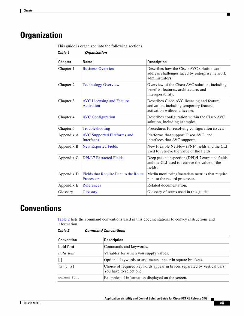
OrganizationThis guide is organized into the following sections.
ConventionsTable 2 lists the command conventions used in this documentations to convey instructions and information.
Table 1 Organization
Chapter Name Description
Chapter 1 Business Overview Describes how the Cisco AVC solution can address challenges faced by enterprise network administrators.
Chapter 2 Technology Overview Overview of the Cisco AVC solution, including benefits, features, architecture, and interoperability.
Chapter 3 AVC Licensing and Feature Activation
Describes Cisco AVC licensing and feature activation, including temporary feature activation without a license.
Chapter 4 AVC Configuration Describes configuration within the Cisco AVC solution, including examples.
Chapter 5 Troubleshooting Procedures for resolving configuration issues.
Appendix A AVC Supported Platforms and Interfaces
Platforms that support Cisco AVC, and interfaces that AVC supports.
Appendix B New Exported Fields New Flexible NetFlow (FNF) fields and the CLI used to retrieve the value of the fields.
Appendix C DPI/L7 Extracted Fields Deep packet inspection (DPI)/L7 extracted fields and the CLI used to retrieve the value of the fields.
Appendix D Fields that Require Punt to the Route Processor
Media monitoring/metadata metrics that require punt to the record processor.
Appendix E References Related documentation.
Glossary Glossary Glossary of terms used in this guide.
Table 2 Command Conventions
Convention Description
bold font Commands and keywords.
italic font Variables for which you supply values.
[ ] Optional keywords or arguments appear in square brackets.
{x | y | z} Choice of required keywords appear in braces separated by vertical bars. You have to select one.
screen font Examples of information displayed on the screen.
viiApplication Visibility and Control Solution Guide for Cisco IOS XE Release 3.9S
OL-29170-03

Chapter
Note Means reader take note. Notes contain helpful suggestions or references to additional information and material.
Caution This symbol means reader be careful. In this situation, you might do something that could result in equipment damage or loss of data.
Tip Means the following information will help you solve a problem. The tips information might not be troubleshooting or even an action, but could be useful information, similar to a Timesaver.
Related DocumentationFor more information, see Appendix E, “References,” or visit:
http://www.cisco.com/go/avc
Searching for Cisco DocumentsTo search an HTML document using a web browser, use the Ctrl+F (Windows) or Cmd+F (Apple) sequences. In most browsers the option to search whole words only, invoke case sensitivity, or search forward and backward are also available.
To search a PDF document in Adobe Reader, use the basic Find toolbar (Ctrl+F) or the Full Reader Search window (Shift+Ctrl+F). Use the Find toolbar to find words or phrases within one specific document. Use the Full Reader Search window to search multiple PDF files simultaneously as well as change case sensitivity, and other options. Adobe Reader comes with online help with more information regarding searching PDF documents.
Obtaining Documentation and Submitting a Service RequestFor information on obtaining documentation, submitting a service request, and gathering additional information, see the monthly What’s New in Cisco Product Documentation, which also lists all new and revised Cisco technical documentation:
http://www.cisco.com/en/US/docs/general/whatsnew/whatsnew.html
boldface screen font Examples of information you have to enter.
< > Nonprinting characters, for example: passwords, appear in angle brackets in contexts where italics are note available.
[ ] Default responses to system prompts appear in square brackets.
Table 2 Command Conventions
Convention Description
viiiApplication Visibility and Control Solution Guide for Cisco IOS XE Release 3.9S
OL-29170-03

Chapter
Subscribe to the What’s New in Cisco Product Documentation as an RSS feed and set content to be delivered directly to your desktop using a reader application. The RSS feeds are a free service. Cisco currently supports RSS Version 2.0.
ixApplication Visibility and Control Solution Guide for Cisco IOS XE Release 3.9S
OL-29170-03

Chapter
xApplication Visibility and Control Solution Guide for Cisco IOS XE Release 3.9S
OL-29170-03

Application Visibility and COL-29170-03
C H A P T E R 1
Business OverviewRevised: August 14, 2013, OL-29170-03
IntroductionEnterprise networks are carrying a growing volume of both business and recreational web traffic. Often business applications, including cloud applications such as Cisco WebEx, use the same HTTP and HTTPS protocols used by recreational web traffic. This complicates the task of optimizing network performance.
To optimize network performance and define policy for each of the applications utilizing the network, administrators need detailed visibility into the different types of applications running on the network.
The Cisco Application Visibility and Control (AVC) solution offers truly innovative and powerful capabilities of application awareness in enterprise networks. AVC incorporates into the routing devices application recognition and performance monitoring capabilities traditionally available as dedicated appliances. This integrated approach simplifies network operations, maximizes the return on network investments, and reduces the total cost of ownership.
With application awareness built into the network infrastructure, plus visibility into the performance of applications running on the network, AVC enables per-application policy for granular control of application bandwidth use, resulting in a better end user experience.
1-1ontrol Solution Guide for Cisco IOS XE Release 3.9S

Chapter 1 Business Overview Business Use Case
Business Use CaseThe following use case illustrates how Cisco AVC can improve the user experience.
A user asks: “Why is Exchange running so slowly?”
IT engineers need answers to questions such as:
• Is Exchange actually running slowly? What are the users seeing?
• Where is the delay: branch LAN, WAN, data center LAN, or server?
• If the delay is in the network, why?
– What is the mix of application traffic?
– What are the key network performance metrics?
To solve the problem, IT engineers need to determine the best option. Cisco AVC offers tools to help find the best option.
• De-prioritize or block competing non-critical traffic.
Cisco QoS tools can help.
• Send different applications over different routes.
Cisco Performance Routing (PfR) can help.
• Squeeze more traffic over the same WAN links.
Cisco Wide Area Application Services (WAAS) WAN optimization can help.
• Reduce apparent application latency over the WAN.
Cisco Wide Area Application Services (WAAS) application acceleration can help.
Or...
• Need to add more capacity?
Cisco AVC integration with management and reporting tools, such as Cisco Prime Infrastructure, can help provide the data needed for planning new capacity.
1-2Application Visibility and Control Solution Guide for Cisco IOS XE Release 3.9S
OL-29170-03

Application Visibility and COL-29170-03
C H A P T E R 2
Technology OverviewRevised: August 14, 2013, OL-29170-03This overview of AVC technology includes the following topics:
• Overview, page 2-1
• AVC Features and Capabilities, page 2-2
• AVC Architecture, page 2-4
• Interoperability of AVC with other Services, page 2-7
• Major External Interfaces, page 2-10
OverviewThe Cisco Application Visibility and Control (AVC) solution leverages multiple technologies to recognize, analyze, and control over 1000 applications, including voice and video, email, file sharing, gaming, peer-to-peer (P2P), and cloud-based applications. AVC combines several Cisco IOS XE components, as well as communicating with external tools, to integrate the following functions into a powerful solution.
• Application Recognition
Operating on Cisco IOS XE, NBAR2 utilizes innovative deep packet inspection (DPI) technology to identify a wide variety of applications within the network traffic flow, using L3 to L7 data.
NBAR2 can monitor over 1000 applications, and supports Protocol Pack updates for expanding application recognition, without requiring IOS upgrade or router reload.
• Metrics Collection and Exporting
Metric providers, an embedded monitoring agent, and Flexible NetFlow combine to provide a wide variety of network metrics data. The monitoring agent collects:
– TCP performance metrics such as bandwidth usage, response time, and latency.
– RTP performance metrics such as packet loss and jitter.
Performance metrics can be measured at multiple points within the router.
Metrics are aggregated and exported in NetFlow v9 or IPFIX format to a management and reporting package. Metrics records are sent out directly from the data plane when possible, to maximize system performance. However, if more complex processing is required on the router, such as if the user requests that the router keep a history of exported records, the records may be exported from the route processor at a lower speed.
2-1ontrol Solution Guide for Cisco IOS XE Release 3.9S
Chapter 2 Technology Overview AVC Features and Capabilities
• Management and Reporting Systems
Management and reporting systems, such as Cisco Prime Infrastructure or third-party tools, receive the network metrics data in Netflow v9 or IPFIX format, and provide a wide variety of system management and reporting functions. These functions include configuring metrics reporting, creating application and network performance reports, system provisioning, configuring alerts, and assisting in troubleshooting.
Using the Cisco Prime Infrastructure management console, an administrator can configure each router in the network remotely by a GUI.
• Control
Administrators can use industry-leading Quality of Service (QoS) capabilities to control application prioritization, manage application bandwidth, and so on. Cisco QoS employs the same deep packet inspection (DPI) technology used by NBAR2, to enable Cisco ASR 1000 routers to reprioritize critical applications and enforce application bandwidth use.
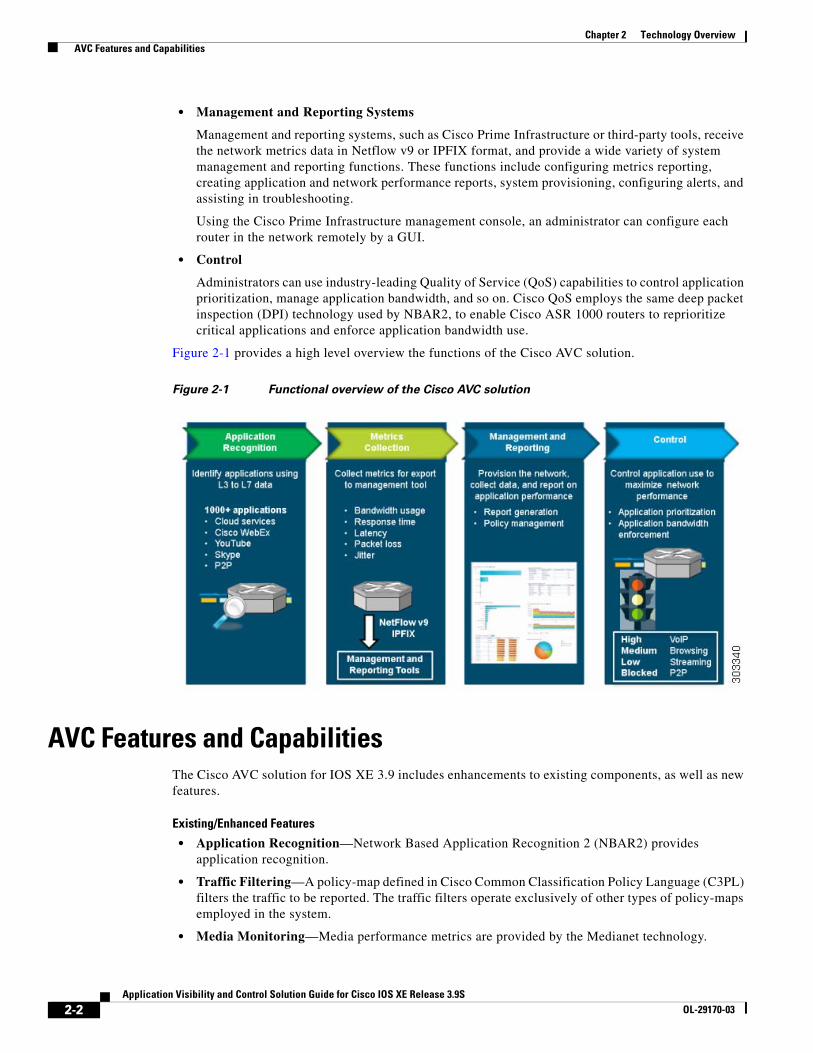
Figure 2-1 provides a high level overview the functions of the Cisco AVC solution.
Figure 2-1 Functional overview of the Cisco AVC solution
AVC Features and CapabilitiesThe Cisco AVC solution for IOS XE 3.9 includes enhancements to existing components, as well as new features.
Existing/Enhanced Features
• Application Recognition—Network Based Application Recognition 2 (NBAR2) provides application recognition.
• Traffic Filtering—A policy-map defined in Cisco Common Classification Policy Language (C3PL) filters the traffic to be reported. The traffic filters operate exclusively of other types of policy-maps employed in the system.
• Media Monitoring—Media performance metrics are provided by the Medianet technology.
2-2Application Visibility and Control Solution Guide for Cisco IOS XE Release 3.9S
OL-29170-03

Chapter 2 Technology Overview AVC Features and Capabilities
• Accounting:
– Accounting of all metrics performed by Flexible NetFlow (FNF) and the IPFIX exporter.
– Multiple parallel monitors with overlapping data for the same traffic permitted.
– Flexible record keys provide different aggregation schemes for different traffic types.
• Unified Solution—Unifies the technologies of several reporting/control solutions. AVC technologies include the configuration mechanism, metrics, and reports of such components as TCP performance, Medianet, and so on.
• Infrastructure Enhancements—A common infrastructure, Metric Mediation Agent (MMA) enables adding stateful and derived parameters with dynamic registration. The infrastructure provides aggregation of connections, history, and alarms from the route processor at a lower speed than the data path export.
• TCP Performance Metrics—This release adds several TCP performance measurements for traffic performance reporting.
• Interoperability with AppNav—AppNav is the Wide Area Application Services (WAAS) diversion mechanism. Beginning with IOS XE release 3.8, AVC provides statistics before and after the AppNav WAAS service controller (AppNav SC), as well as inspecting and reporting application information on optimized traffic.
• Packet Capture—Cisco Embedded Packet Capture (EPC) technology performs packet capture.
• Cisco Prime Infrastructure—The Cisco Prime Infrastructure management and reporting system is an integral part of the Cisco AVC solution and provides extensive management and reporting features, including provisioning the system, storing exported data, and generating reports.
• IPv6 Support—The Cisco AVC solution supports both IPv4 and IPv6.
New AVC Features in IOS XE 3.9
The following are new features in IOS XE 3.9:
• Enhanced Connection/Transaction Metrics—Beginning with this release, Flexible NetFlow (FNF) monitors can report on individual transactions within a flow. This enables greater resolution for traffic metrics. For more information, see: Connection/Transaction Metrics, page 4-15
• QoS Metrics—AVC provides new monitors for collecting metrics related to Quality of Service (QoS) policy. Monitors can indicate:
– Packets dropped on an interface, per QoS queue, due to a QoS policy that limits resources available to a specific type of traffic.
– Class hierarchy (indicating traffic priority) of a reported flow, as determined by the QoS policy map.
For more information, see: QoS Metrics, page 4-9
• Support on Cisco Cloud Services Router—AVC is supported on the new Cisco Cloud Services Router (CSV)-1000V. For more information, see: Licensing and Feature Activation, page 3-1
2-3Application Visibility and Control Solution Guide for Cisco IOS XE Release 3.9S
OL-29170-03

Chapter 2 Technology Overview AVC Architecture
AVC ArchitectureThe following Cisco AVC components are described in this section:
• NBAR2, page 2-5
• Metric Mediation Agent, page 2-5
• Metric Providers, page 2-5
• Flexible NetFlow, page 2-6
• QoS, page 2-6
• Embedded Packet Capture, page 2-6
• Common Flow Table, page 2-6
• Cisco Management and Reporting System: Cisco Prime Infrastructure, page 2-6
Figure 2-2 describes the components in the Cisco AVC architecture.
Figure 2-2 AVC Architecture for Cisco IOS XE
2-4Application Visibility and Control Solution Guide for Cisco IOS XE Release 3.9S
OL-29170-03

Chapter 2 Technology Overview AVC Architecture
NBAR2
Network Based Application Recognition 2 (NBAR2) provides native stateful deep packet inspection (DPI) capabilities. NBAR2 is the next generation of NBAR, enhancing the application recognition engine to support more than 1000 applications.
NBAR2 provides powerful capabilities, including:
• Categorizing applications into meaningful terms, such as category, sub-category, application group, and so on. This categorization simplifies report aggregation and control configuration.
• Field extraction of data such as HTTP URL, SIP domain, mail server, and so on. The extracted application information can be used for classification or can be exported by IPFIX to the collector for creating reports.
• Customized definition of applications, based on ports, payload values, or URL/Host of HTTP traffic.
• The set of attributes for each protocol can be customized.
Additional Application Protocol Definitions
With NBAR2 Protocol Packs, new and updated application signatures can be loaded into a router without upgrading the software image. Major protocol packs providing new and updated signatures are released periodically. Minor protocol packs are released between major releases; they provide updates and bug fixes. For information about protocol pack support, visit: http://www.cisco.com/en/US/docs/ios-xml/ios/qos_nbar/prot_lib/config_library/nbar-prot-pack-library.html
In addition to the predefined application protocols, you can create customized application definitions based on ports, payload values, or URL/Host of the HTTP traffic. Protocol attributes, such as application categorization, sub-categorization, application group, and so on, can also be customized.
For more information, visit: http://www.cisco.com/go/nbar
Metric Mediation Agent
The Metric Mediation Agent (MMA) is an infrastructure element added to the AVC solution in the IOS XE 3.8 release. MMA manages, correlates, and aggregates metrics from different metric providers. It provides the following functions:
• Controls traffic monitoring and filtering policy.
• Correlates data from multiple metric providers (see Metric Providers, page 2-5) into the same record.
• Aggregates metrics.
• Supports history and alert functions. This requires sending the metrics records to the route processor (RP) before exporting them to the management and reporting tools.
Metric Providers
Metric providers collect and calculate metrics and provide them to the Metric Mediation Agent (MMA) for correlation. There are a variety of metric providers: some collect simple, stateless metrics per packet, while other more complex metric providers track states and collect metrics per flow, transforming the metrics at the time of export and making sophisticated calculations. These transformations may require punting of records to the route processor (RP) before the metrics are exported to the management and reporting system.
2-5Application Visibility and Control Solution Guide for Cisco IOS XE Release 3.9S
OL-29170-03

Chapter 2 Technology Overview AVC Architecture
The MMA compiles multiple metric providers of different types into the same record (see Metric Mediation Agent, page 2-5).
Flexible NetFlow
Netflow/IPFIX is the industry standard for acquiring operational data from IP networks to enable network planning, monitoring traffic analysis, and IP accounting. Flexible NetFlow (FNF) enables customizing traffic analysis parameters according to specific requirements. The AVC solution is compatible with NetFlow v9 (RFC-3954) and IPFIX (RFC-5101).
For more information, visit: http://www.cisco.com/go/fnf
QoS
Cisco Quality of Service (QoS) provides prioritization, shaping, or rate-limiting of traffic. QoS can place designated applications into specific QoS classes/queues. This enables:
• Placing high priority, latency-sensitive traffic into a priority queue.
• Guaranteeing a minimum bandwidth for an individual application or for a group of applications within a QoS traffic class.
Similarly, QoS can also be used for “policing” or managing non-enterprise, recreational applications such as YouTube and Facebook.
The Cisco AVC solution integrates QoS functionality with NBAR2. QoS can use application information provided by NBAR2 in managing network traffic. The QoS class-map statements enable matching to NBAR2-supported applications and L7 application fields (such as HTTP URL or Host), as well as to NBAR2 attributes. Class-map statements can coexist with all other traditional QoS match attributes, such as IP, subnet, and DSCP.
For more information, visit: http://www.cisco.com/go/qos
Embedded Packet Capture
Embedded Packet Capture (EPC) enables capturing the entire traffic for a given traffic class. The capture is limited only by available memory. The management and reporting system can read packets captured as a packet capture (pcap) file.
For more information, visit: http://www.cisco.com/go/epc
Common Flow Table
The Common Flow Table (CFT) manages L4 connections and enables storing and retrieving states for each flow. Using a common flow table optimizes use of system memory and improves performance by storing and running data for each flow only once. The CFT standardizes flow management across the entire system.
Cisco Management and Reporting System: Cisco Prime Infrastructure
Cisco Prime Infrastructure provides infrastructure lifecycle management and end-to-end visibility of services and applications for improved troubleshooting. It combines the solution lifecycle from design phase to monitor and troubleshooting phase.
2-6Application Visibility and Control Solution Guide for Cisco IOS XE Release 3.9S
OL-29170-03

Chapter 2 Technology Overview Interoperability of AVC with other Services
For configuration, Cisco Prime Infrastructure has a provisioning GUI and built-in templates for enabling AVC capabilities on network devices.
For monitoring, Cisco Prime Infrastructure leverages the rich information provided by the network infrastructure, such as routers, and provides network administrators with a single tool for monitoring both network and application performance.
Network administrators can use Cisco Prime Infrastructure to drill down from an enterprise-wide network view to an individual user at a site, to proactively monitor and troubleshoot network and application performance problems.
For more information, visit: http://www.cisco.com/go/primeinfrastructure
Interoperability of AVC with other ServicesCisco AVC is interoperable with many router features and services. This section provides additional information about AVC integration with AppNav WAAS, NAT, and VRF.
• Interoperability with AppNav WAAS, page 2-7
• Interoperability with NAT and VRF, page 2-9
Interoperability with AppNav WAASFigure 2-3 shows a typical deployment scenario for Cisco AVC, demonstrating the integration with WAAS and the combination of optimized and pass-through traffic.
Figure 2-3 Typical AVC deployment
2-7Application Visibility and Control Solution Guide for Cisco IOS XE Release 3.9S
OL-29170-03

Chapter 2 Technology Overview Interoperability of AVC with other Services
Attachment to a WAAS-Enabled Interface
Cisco Wide Area Application Services (WAAS) provides WAN optimization and application acceleration. The Cisco AVC solution operates closely with Cisco WAAS, reporting performance on both optimized and unoptimized traffic.
Figure 2-4 shows two recommended locations for metric collection. The monitoring location on the WAN interface collects metrics for optimized and unoptimized traffic. The monitoring location on the unoptimized virtual interface collects metrics for unoptimized traffic.
Figure 2-4 Recommended WAAS Monitoring Points
Because optimized traffic may be exported twice (pre/post WAAS), a new segment field, servicesWaasSegment, is exported within the record in order to describe the type of traffic at the monitoring location. Table 2-1 describes the segment definitions.
Table 2-1 AppNav “servicesWaasSegment” field values
For pass-through traffic (bypassing WAAS), the servicesWaasPassThroughReason field indicates the reason for pass-through. See Appendix B, “New Exported Fields” for a description of this field.
Value Description
0 Unknown
1 Client unoptimized
2 Server optimized
4 Client optimized
8 Server unoptimized
16 Pass-through
2-8Application Visibility and Control Solution Guide for Cisco IOS XE Release 3.9S
OL-29170-03
Chapter 2 Technology Overview Interoperability of AVC with other Services
Application Recognition on Optimized Traffic
The interoperability of Cisco AVC and WAAS enables executing traffic policies and monitoring on optimized traffic, utilizing NBAR2 application recognition.
Note When using WAAS, application L7 fields are only supported on unoptimized traffic. URL records must be attached on the unoptimized AppNav virtual interface.
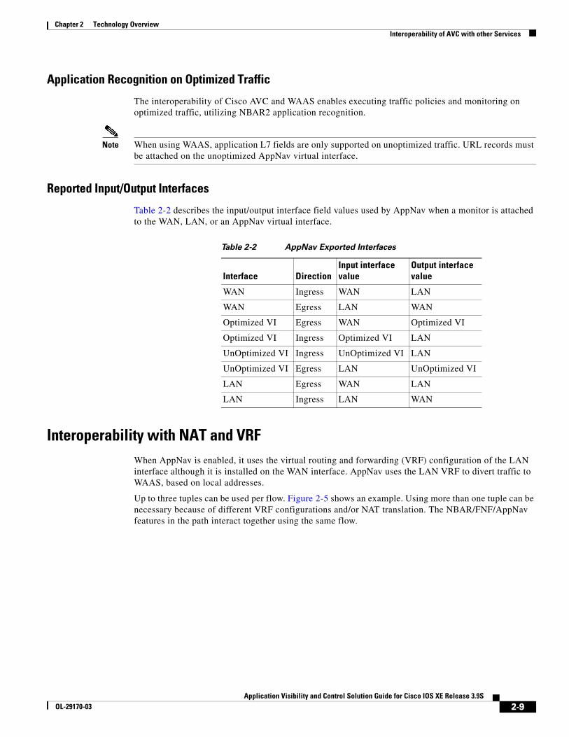
Reported Input/Output Interfaces
Table 2-2 describes the input/output interface field values used by AppNav when a monitor is attached to the WAN, LAN, or an AppNav virtual interface.
Table 2-2 AppNav Exported Interfaces
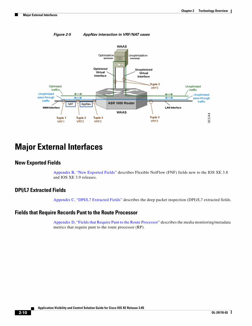
Interoperability with NAT and VRFWhen AppNav is enabled, it uses the virtual routing and forwarding (VRF) configuration of the LAN interface although it is installed on the WAN interface. AppNav uses the LAN VRF to divert traffic to WAAS, based on local addresses.
Up to three tuples can be used per flow. Figure 2-5 shows an example. Using more than one tuple can be necessary because of different VRF configurations and/or NAT translation. The NBAR/FNF/AppNav features in the path interact together using the same flow.
Interface DirectionInput interface value
Output interface value
WAN Ingress WAN LAN
WAN Egress LAN WAN
Optimized VI Egress WAN Optimized VI
Optimized VI Ingress Optimized VI LAN
UnOptimized VI Ingress UnOptimized VI LAN
UnOptimized VI Egress LAN UnOptimized VI
LAN Egress WAN LAN
LAN Ingress LAN WAN
2-9Application Visibility and Control Solution Guide for Cisco IOS XE Release 3.9S
OL-29170-03
Chapter 2 Technology Overview Major External Interfaces
Figure 2-5 AppNav interaction in VRF/NAT cases
Major External Interfaces
New Exported Fields
Appendix B, “New Exported Fields” describes Flexible NetFlow (FNF) fields new to the IOS XE 3.8 and IOS XE 3.9 releases.
DPI/L7 Extracted Fields
Appendix C, “DPI/L7 Extracted Fields” describes the deep packet inspection (DPI)/L7 extracted fields.
Fields that Require Records Punt to the Route Processor
Appendix D, “Fields that Require Punt to the Route Processor” describes the media monitoring/metadata metrics that require punt to the route processor (RP).
2-10Application Visibility and Control Solution Guide for Cisco IOS XE Release 3.9S
OL-29170-03

Application Visibility and COL-29170-03
C H A P T E R 3
AVC Licensing and Feature ActivationRevised: August 14, 2013, OL-29170-03
This chapter addresses Cisco AVC licensing and includes the following topic(s):
• Licensing and Feature Activation, page 3-1
Licensing and Feature ActivationActivating full Cisco AVC functionality on supported platforms may require additional feature licensing and activation. See AVC Supported Platforms, page A-1 for information about supported platforms.
Feature activation is accomplished differently for different platforms. See the following sections for details:
• AVC Licensing for Cisco ASR 1000 Series Routers, page 3-2
• AVC Licensing for Cisco CSR 1000V, page 3-3
AVC FunctionalityThe AES or AIS license adds advanced AVC functionality, as summarized in Table 3-1.
Table 3-1 AVC feature licensing
FeatureWithout Additional Licensing
With AES or AIS Licensing
NBAR1 Protocol Pack
1. NBAR = Cisco Network Based Application Recognition
Standard Advanced
NBAR custom protocols Not available Available
NBAR customization of application protocol attributes
Not available Available
NBAR HTTP field extraction Not available Available
NBAR IPv6 tunneling Not available Available
WAAS2
2. WAAS = Cisco Wide Area Application Services
Not available Available
3-1ontrol Solution Guide for Cisco IOS XE Release 3.9S

Chapter 3 AVC Licensing and Feature Activation Licensing and Feature Activation
Required IOS XE Image and LicenseTable 3-2 describes the IOS XE image and the license required to activate full AVC functionality for supported models.
Table 3-2 Image/License required for AVC functionality
AVC Licensing for Cisco ASR 1000 Series RoutersSee Table 3-2 for information about the IOS XE image and the license required to activate full AVC functionality.
For additional information about purchasing and installing the AES or AIS license for Cisco ASR 1000 series routers, see:
• Software Activation Configuration Guide, Cisco IOS XE Release 3S
• Cisco ASR 1000 Series Aggregation Services Routers Ordering Guide
Temporary Activation/Deactivation of the AES or AIS License
Cisco ASR 1001 and Cisco ASR 1002-X routers support temporary activation of AES or AIS features before obtaining a license, using the license boot level CLI command. Activating either of these feature sets provides full AVC functionality.
Note Cisco ASR 1000 series models other than Cisco ASR 1001 and Cisco ASR 1002-X do not support temporary license activation.
PlatformIOS XE image required for AVC functionality License
Temporary licence activation supported
Cisco ASR 1001 Cisco ASR 1002-X
Universal AES1 or AIS2
1. AES = Advanced Enterprise Services
2. AIS = Advanced IP Services
Yes
Cisco ASR 1000 Series routers other than ASR 1001 and ASR 1002-X
Note: These platforms are also provided with the IPBASE image, which does not include AVC functionality.
AES or AIS AES or AIS
Note: This license is typically bundled with the AIS or AES image.
No
Cisco CSR-1000V Cloud Services Router
AES AES
Note: The AES license is typically bundled with the AES image provided with the platform.
No
3-2Application Visibility and Control Solution Guide for Cisco IOS XE Release 3.9S
OL-29170-03

Chapter 3 AVC Licensing and Feature Activation Licensing and Feature Activation
Activation
To temporarily activate AES or AIS features, load the AES or AIS image and reboot the router. Execute the following from the console (using adventerprise for the AES image or advipservices for the AIS image):
conf t license boot level [adventerprise | advipservices]endreboot
Deactivation
To deactivate the AES/AIS license features, load the IPbase image and reboot the router. Execute the following from the console:
conf t license boot level ipbase endreboot
AVC Licensing for Cisco CSR 1000VCisco CSR 1000V Cloud Services Routers are provided with an Advanced Enterprise Services (AES) IOS XE image and license, providing full AVC functionality.
3-3Application Visibility and Control Solution Guide for Cisco IOS XE Release 3.9S
OL-29170-03

Chapter 3 AVC Licensing and Feature Activation Licensing and Feature Activation
3-4Application Visibility and Control Solution Guide for Cisco IOS XE Release 3.9S
OL-29170-03
Application Visibility and COL-29170-03
C H A P T E R 4
AVC ConfigurationRevised: August 14, 2013, OL-29170-03
This chapter addresses Cisco AVC configuration and includes the following topics:
• Unified Policy CLI, page 4-1
• Metric Producer Parameters, page 4-2
• Reacts, page 4-2
• NetFlow/IPFIX Flow Monitor, page 4-2
• NetFlow/IPFIX Flow Record, page 4-3
• QoS Metrics, page 4-9
• Connection/Transaction Metrics, page 4-15
• Configuration Examples, page 4-19
Unified Policy CLIBeginning with Cisco IOS XE 3.8, monitoring configuration is done using performance-monitor unified monitor and policy.
policy-map type performance-monitor <policy-name> [no] parameter default account-on-resolution class <class-map name> flow monitor <monitor-name> [sampler <sampler name>] [sampler <sampler name>] monitor metric rtp
Usage Guidelines
• Support for:
– Multiple flow monitors under a class-map.
– Up to 5 monitors per attached class-map.
– Up to 256 classes per performance-monitor policy.
• No support for:
– Hierarchical policy.
– Inline policy.
4-1ontrol Solution Guide for Cisco IOS XE Release 3.9S

Chapter 4 AVC Configuration Metric Producer Parameters
• Metric producer parameters are optional.
• Account-on-resolution (AOR) configuration causes all classes in the policy-map to work in AOR mode, which delays the action until the class-map results are finalized (the application is determined by NBAR2).
Attach policy to the interface using following command:
interface <interface-name> service-policy type performance-monitor <policy-name> {input|output}
Metric Producer ParametersMetric producer-specific parameters are optional and can be defined for each metric producer for each class-map.
Note Cisco IOS XE 3.8 and 3.9 support only MediaNet-specific parameters.
monitor metric rtp clock-rate {type-number| type-name | default} rate max-dropout number max-reorder number min-sequential number ssrc maximum number
ReactsThe react CLI defines the alerts applied to a flow monitor. Applying reacts on the device requires punting the monitor records to the route processor (RP) for alert processing. To avoid the performance reduction of punting the monitor records to the RP, it is preferable when possible to send the monitor records directly to the Management and Reporting system and apply the network alerts in the Management and Reporting system.
react <id> [media-stop|mrv|rtp-jitter-average|transport-packets-lost-rate]
NetFlow/IPFIX Flow MonitorFlow monitor defines monitor parameters, such as record, exporter, and other cache parameters.
flow monitor type performance-monitor <monitor-name> record <name | default-rtp | default-tcp> exporter <exporter-name> history size <size> [timeout <interval>] cache entries <num> cache timeout {{active | inactive | synchronized} <value> | event transaction end} cache type {permanent | normal | immediate} react-map <react-map-name>
Usage Guidelines
• The react-map CLI is allowed under the class in the policy-map. In this case, the monitor must include the exporting of the class-id in the flow record. The route processor (RP) correlates the class-id in the monitor with the class-id where the react is configured.
4-2Application Visibility and Control Solution Guide for Cisco IOS XE Release 3.9S
OL-29170-03

Chapter 4 AVC Configuration NetFlow/IPFIX Flow Record
• Applying history or a react requires punting the record to the RP.
• Export on the “event transaction end” is used to export the records when the connection or transaction is terminated. In this case, the records are not exported based on timeout. Exporting on the event transaction end should be used when detailed connection/transaction granularity is required, and has the following advantages:
– Sends the record close to the time that it has ended.
– Exports only one record on true termination.
– Conserves memory in the cache and reduces the load on the Management and Reporting system.
– Enables exporting multiple transactions of the same flow. (This requires a protocol pack that supports multi-transaction.)
NetFlow/IPFIX Flow RecordThe flow record defines the record fields. With each Cisco IOS release, the Cisco AVC solution supports a more extensive set of metrics.
The sections that follow list commonly used AVC-specific fields as of release IOS XE 3.8, organized by functional groups. These sections do not provide detailed command reference information, but highlight important usage guidelines.
In addition to the fields described below, a record can include any NetFlow field supported by the ASR 1000 platform.
A detailed description of NetFlow fields appears in the Cisco IOS Flexible NetFlow Command Reference. Appendix B, “New Exported Fields” describes new NetFlow exported fields.
Note In this release, the record size is limited to 30 fields (key and non-key fields or match and collect fields).
L3/L4 FieldsThe following are L3/L4 fields commonly used by the Cisco AVC solution.
[collect | match] connection [client|server] [ipv4|ipv6] address[collect | match] connection [client|server] transport port[collect | match] [ipv4|ipv6] [source|destination] address[collect | match] transport [source-port|destination-port][collect | match] [ipv4|ipv6] version[collect | match] [ipv4|ipv6] protocol[collect | match] routing vrf [input|output][collect | match] [ipv4|ipv6] dscp[collect | match] ipv4 ttl[collect | match] ipv6 hop-limitcollect transport tcp option mapcollect transport tcp window-size [minimum|maximum|sum]collect transport tcp maximum-segment-size
Usage Guidelines
The client is determined according to the initiator of the connection.
The client and server fields are bi-directional. The source and destination fields are uni-directional.
4-3Application Visibility and Control Solution Guide for Cisco IOS XE Release 3.9S
OL-29170-03
Chapter 4 AVC Configuration NetFlow/IPFIX Flow Record
L7 FieldsThe following are L7 fields commonly used by the Cisco AVC solution.
[collect | match] application name [account-on-resolution]collect application http urlcollect application http hostcollect application http user-agentcollect application http referercollect application rtsp host-namecollect application smtp servercollect application smtp sendercollect application pop3 servercollect application nntp group-namecollect application sip sourcecollect application sip destination
Usage Guidelines
• The application ID is exported according to RFC-6759.
• Account-On-Resolution configures FNF to collect data in a temporary memory location until the record key fields are resolved. After resolution of the record key fields, FNF combines the temporary data collected with the standard FNF records. Use the account-on-resolution option when the field used as a key is not available at the time that FNF receives the first packet.
The following limitations apply when using Account-On-Resolution:
– Flows ended before resolution are not reported.
– FNF packet/octet counters, timestamp, and TCP performance metrics are collected until resolution. All other field values are taken from the packet that provides resolution or the following packets.
• For information about extracted fields, including the formats in which they are exported, see Appendix C, “DPI/L7 Extracted Fields”.
Interfaces and DirectionsThe following are interface and direction fields commonly used by the Cisco AVC solution:
[collect | match] interface [input|output][collect | match] flow directioncollect connection initiator
Counters and TimersThe following are counter and timer fields commonly used by the Cisco AVC solution:
collect connection client counter bytes [long]collect connection client counter packets [long]collect connection server counter bytes [long]collect connection server counter packets [long]collect counter packets [long]collect counter bytes [long]collect counter bytes ratecollect connection server counter responsescollect connection client counter packets retransmittedcollect connection transaction duration {sum, min, max} collect connection transaction counter complete
4-4Application Visibility and Control Solution Guide for Cisco IOS XE Release 3.9S
OL-29170-03

Chapter 4 AVC Configuration NetFlow/IPFIX Flow Record
collect connection new-connectionscollect connection sum-durationcollect timestamp sys-uptime firstcollect timestamp sys-uptime last
Counter Metrics Added in the Cisco IOS XE 3.9.2 Release
In the Cisco IOS XE 3.9.2 maintenance release, the following counter fields were added:
• Client Bytes—Total L3 bytes sent by the initiator of a connection. Counted for TCP and UDP connections.
collect connection client counter bytes network long
• Server Bytes—Total L3 bytes sent by the responder of a connection. Counted for TCP and UDP connections.
collect connection server counter bytes network long
For addition information about these fields, see Cisco Application Visibility and Control Field Definition Guide for Third-Party Customers.
TCP Performance MetricsThe following are fields commonly used for TCP performance metrics by the Cisco AVC solution:
collect connection delay network to-server {sum, min, max}collect connection delay network to-client {sum, min, max}collect connection delay network client-to-server {sum, min, max}collect connection delay response to-server {sum, min, max}collect connection delay response to-server histogram [bucket1 ... bucket7 | late]collect connection delay response client-to-server {sum, min, max}collect connection delay application {sum, min, max}
Usage Guidelines
The following limitations apply to TCP performance metrics in AVC for IOS XE 3.9:
• All TCP performance metrics must observe bi-directional traffic.
• The policy-map must be applied in both directions.
Figure 4-1 provides an overview of network response time metrics.
Figure 4-1 Network response times
4-5Application Visibility and Control Solution Guide for Cisco IOS XE Release 3.9S
OL-29170-03

Chapter 4 AVC Configuration NetFlow/IPFIX Flow Record
Figure 4-2 provides details of network response time metrics.
Figure 4-2 Network response time metrics in detail
4-6Application Visibility and Control Solution Guide for Cisco IOS XE Release 3.9S
OL-29170-03
Chapter 4 AVC Configuration NetFlow/IPFIX Flow Record
Media Performance MetricsThe following are fields commonly used for media performance metrics by the Cisco AVC solution:
[collect | match] match transport rtp ssrc collect transport rtp payload-typecollect transport rtp jitter mean sumcollect transport rtp jitter [minimum | maximum]collect transport packets lost counter collect transport packets expected countercollect transport packets lost countercollect transport packets lost ratecollect transport event packet-loss countercollect counter packets droppedcollect application media bytes countercollect application media bytes ratecollect application media packets countercollect application media packets ratecollect application media eventcollect monitor event
Usage Guidelines
Some of the media performance fields require punt to the route processor (RP). For more information, see Appendix D, “Fields that Require Punt to the Route Processor”.
L2 InformationThe following are L2 fields commonly used by the Cisco AVC solution:
[collect | match] datalink [source-vlan-id | destination-vlan-id][collect | match] datalink mac [source | destination] address [input | output]
WAAS InteroperabilityThe following are WAAS fields commonly used by the Cisco AVC solution:
[collect | match] services waas segment [account-on-resolution]collect services waas passthrough-reason
Usage Guidelines
Account-On-Resolution configures FNF to collect data in a temporary memory location until the record key fields are resolved. After resolution of the record key fields, FNF combines the temporary data collected with the standard FNF records. Use this option (account-on-resolution) when the field used as a key is not available at the time that FNF receives the first packet.
The following limitations apply when using Account-On-Resolution:
• Flows ended before resolution are not reported.
• FNF packet/octet counters, timestamp and TCP performance metrics are collected until resolution. All other field values are taken from the packet that provides resolution or the following packets.
ClassificationThe following are classification fields commonly used by the Cisco AVC solution:
4-7Application Visibility and Control Solution Guide for Cisco IOS XE Release 3.9S
OL-29170-03

Chapter 4 AVC Configuration NetFlow/IPFIX Flow Record
[collect | match] policy performance-monitor classification hierarchy
Usage Guidelines
Use this field to report the matched class for the performance-monitor policy-map.
NetFlow/IPFIX Option TemplatesNetFlow option templates map IDs to string names and descriptions:
flow exporter my-exporter export-protocol ipfix template data timeout <timeout> option interface-table timeout <timeout> option vrf-table timeout <timeout> option sampler-table timeout <timeout> option application-table timeout <timeout> option application-attributes timeout <timeout> option sub-application-table timeout <timeout> option c3pl-class-table timeout <timeout> option c3pl-policy-table timeout <timeout>
NetFlow/IPFIX Show commandsUse the following commands to show or debug NetFlow/IPFIX information:
show flow monitor type performance-monitor [<name> [cache [raw]]]show flow record type performance-monitorshow policy-map type performance-monitor [<name> | interface]
NBAR Attribute CustomizationUse the following commands to customize the NBAR attributes:
[no] ip nbar attribute-map <profile name> attribute category <category> attribute sub-category <sub-category> attribute application-group <application-group> attribute tunnel <tunnel-info> attribute encrypted <encrypted-info> attribute p2p-technology <p2p-technology-info>[no] ip nbar attribute-set <protocol-name> <profile name>
Note These commands support all attributes defined by the NBAR2 Protocol Pack, including custom-category, custom-sub-category, and custom-group available in Protocol Pack 3.1.
NBAR Customize ProtocolsUse the following commands to customize NBAR protocols and assign a protocol ID. A protocol can be matched based on HTTP URL/Host or other parameters:
ip nbar custom <protocol-name> [http {[url <urlregexp>] [host <hostregexp>]}] [offset [format value]] [variable field-name field-length] [source | destination] [tcp | udp ] [range start end | port-number ] [id <id>]
4-8Application Visibility and Control Solution Guide for Cisco IOS XE Release 3.9S
OL-29170-03

Chapter 4 AVC Configuration QoS Metrics
Packet Capture ConfigurationUse the following commands to enable packet capture:
policy-map type packet-services <policy-name>class <class-name>
capture limit packet-per-sec <pps> allow-nth-pak <np> duration <duration> packets <packets> packet-length <len>
buffer size <size> type <type>
interface <interface-name> service-policy type packet-services <policy-name> [input|output]
QoS MetricsThis section describes how to configure Flexible NetFlow (FNF) monitors to include Quality of Service (QoS) metrics.
Background
FNF Monitors
Flexible NetFlow (FNF) enables monitoring traffic on router interfaces. FNF monitors are configured for a specific interface to monitor the traffic on that interface. At defined intervals, the monitor sends collected traffic data to a “collector,” which can be a component within the router or an external component.
Beginning with Cisco AVC for IOS XE Release 3.9, FNF records include new fields for QoS metrics.
QoS
QoS configuration is based on class maps and policy maps. Class maps categorize traffic; policy maps determine how to handle the traffic. Based on the policy identified for each packet, the packet is placed into a specific QoS queue, which determines the priority and pattern of transmission. Each queue is identified by a Queue ID field.
For additional information about QoS, visit: http://www.cisco.com/go/qos
Exported MetricsAVC enables configuration of QoS Packet Drop and QoS Class Hierarchy monitors on an interface, using one or more of the following QoS metrics, which can be included in exported FNF records:
• Queue ID—Identifies a QoS queue.
• Queue Packet Drops—Packets dropped (on the monitored interface) per QoS queue, due to a QoS policy that limits resources available to a specific type of traffic.
• Class Hierarchy—Class hierarchy of the reported flow. The class hierarchy is determined by the QoS policy map and determines the traffic priority.
4-9Application Visibility and Control Solution Guide for Cisco IOS XE Release 3.9S
OL-29170-03
Chapter 4 AVC Configuration QoS Metrics
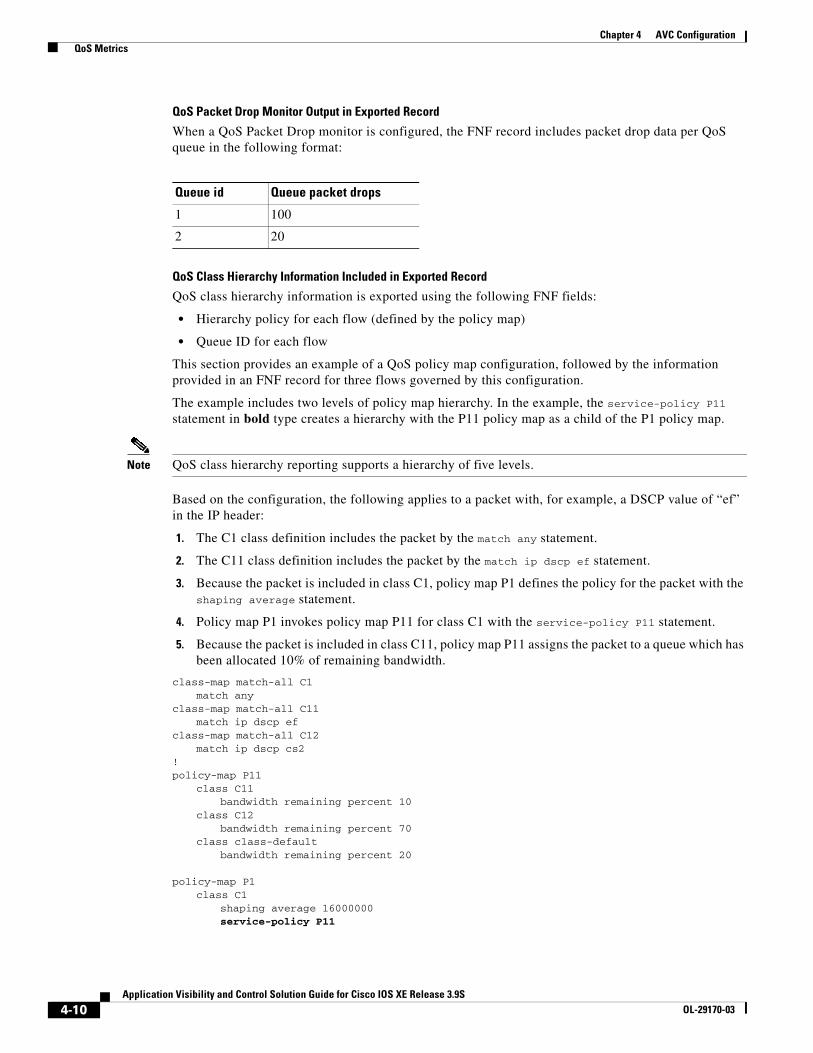
QoS Packet Drop Monitor Output in Exported Record
When a QoS Packet Drop monitor is configured, the FNF record includes packet drop data per QoS queue in the following format:
QoS Class Hierarchy Information Included in Exported Record
QoS class hierarchy information is exported using the following FNF fields:
• Hierarchy policy for each flow (defined by the policy map)
• Queue ID for each flow
This section provides an example of a QoS policy map configuration, followed by the information provided in an FNF record for three flows governed by this configuration.
The example includes two levels of policy map hierarchy. In the example, the service-policy P11 statement in bold type creates a hierarchy with the P11 policy map as a child of the P1 policy map.
Note QoS class hierarchy reporting supports a hierarchy of five levels.
Based on the configuration, the following applies to a packet with, for example, a DSCP value of “ef” in the IP header:
1. The C1 class definition includes the packet by the match any statement.
2. The C11 class definition includes the packet by the match ip dscp ef statement.
3. Because the packet is included in class C1, policy map P1 defines the policy for the packet with the shaping average statement.
4. Policy map P1 invokes policy map P11 for class C1 with the service-policy P11 statement.
5. Because the packet is included in class C11, policy map P11 assigns the packet to a queue which has been allocated 10% of remaining bandwidth.
class-map match-all C1match any
class-map match-all C11match ip dscp ef
class-map match-all C12match ip dscp cs2
!policy-map P11
class C11bandwidth remaining percent 10
class C12bandwidth remaining percent 70
class class-defaultbandwidth remaining percent 20
policy-map P1class C1
shaping average 16000000service-policy P11
Queue id Queue packet drops
1 100
2 20
4-10Application Visibility and Control Solution Guide for Cisco IOS XE Release 3.9S
OL-29170-03

Chapter 4 AVC Configuration QoS Metrics
Table 4-1 shows an example of the information provided in an FNF record for three flows governed by this configuration.
Table 4-1 QoS Class Hierarchy Information in the FNF record
In Table 4-1, policy and class information is shown using the true policy and class names, such as P1 and C1. However, the FNF record exports policy and class names using numerical identifiers in place of policy and class names. The monitor periodically outputs a “policy option template” and a “class option template” indicating the policy names and class names that correspond to the numbers used in the exported FNF records. These option templates are defined in the exporter configuration, using statements such as the following, which create the option templates and indicate the time interval at which the monitor outputs the option template information:
option c3pl-class-table timeout <timeout>option c3pl-policy-table timeout <timeout>
Configuration
Enabling QoS Metric Collection
Enabling
To enable the QoS metrics collection feature for the platform, enter global configuration mode using configure terminal, then use the following QoS configuration command. The command causes QoS to begin collecting QoS metrics for FNF.
Note Enabling QoS metrics collection requires resetting all performance monitors on the device.
platform qos performance-monitor
Verifying
To verify that QoS metrics collection is enabled, use the following command:
show platform hardware qfp active feature qos config global
The following is an example of the output of the command:
Marker statistics are: disabledMatch per-filter statistics are: disabledMatch per-ace statistics are: disabledPerformance-Monitor statistics are: enabled
Flow Hierarchy Queue id
Flow 1 P1, C1, C11 1
Flow 2 P1, C1, C11 1
Flow 3 P1, C1, C12 2
4-11Application Visibility and Control Solution Guide for Cisco IOS XE Release 3.9S
OL-29170-03
Chapter 4 AVC Configuration QoS Metrics
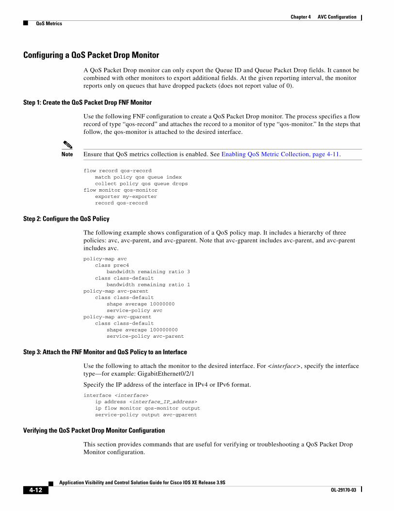
Configuring a QoS Packet Drop Monitor
A QoS Packet Drop monitor can only export the Queue ID and Queue Packet Drop fields. It cannot be combined with other monitors to export additional fields. At the given reporting interval, the monitor reports only on queues that have dropped packets (does not report value of 0).
Step 1: Create the QoS Packet Drop FNF Monitor
Use the following FNF configuration to create a QoS Packet Drop monitor. The process specifies a flow record of type “qos-record” and attaches the record to a monitor of type “qos-monitor.” In the steps that follow, the qos-monitor is attached to the desired interface.
Note Ensure that QoS metrics collection is enabled. See Enabling QoS Metric Collection, page 4-11.
flow record qos-recordmatch policy qos queue indexcollect policy qos queue drops
flow monitor qos-monitorexporter my-exporterrecord qos-record
Step 2: Configure the QoS Policy
The following example shows configuration of a QoS policy map. It includes a hierarchy of three policies: avc, avc-parent, and avc-gparent. Note that avc-gparent includes avc-parent, and avc-parent includes avc.
policy-map avcclass prec4
bandwidth remaining ratio 3class class-default
bandwidth remaining ratio 1policy-map avc-parent
class class-defaultshape average 10000000service-policy avc
policy-map avc-gparentclass class-default
shape average 100000000service-policy avc-parent
Step 3: Attach the FNF Monitor and QoS Policy to an Interface
Use the following to attach the monitor to the desired interface. For <interface>, specify the interface type—for example: GigabitEthernet0/2/1
Specify the IP address of the interface in IPv4 or IPv6 format.
interface <interface>ip address <interface_IP_address>ip flow monitor qos-monitor outputservice-policy output avc-gparent
Verifying the QoS Packet Drop Monitor Configuration
This section provides commands that are useful for verifying or troubleshooting a QoS Packet Drop Monitor configuration.
4-12Application Visibility and Control Solution Guide for Cisco IOS XE Release 3.9S
OL-29170-03

Chapter 4 AVC Configuration QoS Metrics
Verifying that the Monitor is Allocated
Use the following command to verify that the QoS monitor exists:
show flow monitor
Use the following commands to verify additional monitor details:
show flow monitor qos-monitorshow flow monitor qos-monitor cacheshow flow monitor qos-monitor statisticsshow platform hardware qfp active feature fnf client flowdef name qos-recordshow platform hardware qfp active feature fnf client monitor name qos-monitor
Verifying QoS queues and Class-Hierarchies
The following show commands display the statistics that QoS has collected. “gigX/X/X” refers to the interface for which the monitor has been configured.
show policy-map int gigX/X/Xshow platform hardware qfp active feature qos queue output all
Verifying FNF-QOS FIA Activation
Use the following show command to verify that the FNF-QoS FIA (feature activation array) is enabled on the interface (GigabitEthernet0/2/1 in this example):
show platform hardware qfp active interface if-name GigabitEthernet0/2/1
Verifying the FNF Monitor and Record
Use the following debug commands to verify that the FNF monitor and record have been created:
debug platform software flow flow-def errorsdebug platform software flow monitor errorsdebug platform software flow interface errors
debug platform hardware qfp active feature fnf server tracedebug platform hardware qfp active feature fnf server infodebug platform hardware qfp active feature fnf server error
Configuring a QoS Class Hierarchy Monitor
In contrast to the QoS Packet Drop monitor, a QoS Class Hierarchy monitor can be combined with another monitor to export additional metrics.
Step 1: Create the QoS Class Record
The following example configuration creates a QoS class record. The process specifies a record of type “qos-class-record.” The example specifies “ipv4 source” and “ipv4 destination” addresses, but you can configure the record to match according to other criteria.
4-13Application Visibility and Control Solution Guide for Cisco IOS XE Release 3.9S
OL-29170-03

Chapter 4 AVC Configuration QoS Metrics
Note Ensure that QoS metrics collection is enabled. See Enabling QoS Metric Collection, page 4-11.
flow record qos-class-recordmatch ipv4 source addressmatch ipv4 destination addresscollect counter bytescollect counter packetscollect policy qos classification hierarchycollect policy qos queue index
Step 2: Create the QoS Class Hierarchy Monitor
Use the following FNF configuration to create a QoS Class Hierarchy monitor. The process specifies a monitor of type “class-hier-monitor.” In the steps that follow, the monitor is attached to the desired interface.
flow monitor class-hier-monitorexporter my-exporter record qos-class-record
Step 3: Attach the QoS Class Hierarchy Monitor to an Interface
Use the following to attach the monitor to the desired interface. For <interface>, specify the interface type—for example: GigabitEthernet0/2/1
Specify the IP address of the interface in IPv4 or IPv6 format.
Note Attaching the service-policy to the interface, as indicated by the “service-policy” statement below, is a required step.
interface <interface>ip address <interface_IP_address>ip flow monitor class-hier-monitor output service-policy output avc-gparent
Verifying the QoS Class Hierarchy Monitor Configuration
This section provides commands that are useful for verifying or troubleshooting a QoS Class Hierarchy Monitor configuration.
Verifying that the Monitor is Allocated
Use the following command to verify that the QoS monitor exists:
show flow monitor
Use the following commands to verify additional details:
show flow monitor class-hier-monitorshow flow monitor class-hier-monitor cacheshow flow monitor class-hier-monitor statistics show platform hardware qfp active feature fnf client flowdef name qos-class-recordshow platform hardware qfp active feature fnf client monitor name qos-monitor
4-14Application Visibility and Control Solution Guide for Cisco IOS XE Release 3.9S
OL-29170-03

Chapter 4 AVC Configuration Connection/Transaction Metrics
Verifying FNF-QOS FIA Activation
In the following feature invocation array (FIA) verification example, the interface is GigabitEthernet0/2/1.
show platform hardware qfp active interface if-name GigabitEthernet0/2/1
Verifying the FNF Monitor and Record
Use the following debug commands to verify that the FNF monitor and record have been created:
debug platform software flow flow-def errorsdebug platform software flow monitor errorsdebug platform software flow interface errors debug platform hardware qfp active feature fnf server tracedebug platform hardware qfp active feature fnf server infodebug platform hardware qfp active feature fnf server error
Connection/Transaction MetricsBeginning with Cisco AVC for IOS XE Release 3.9, Flexible NetFlow (FNF) monitors can report on individual transactions within a flow. This enables greater resolution for traffic metrics. This section describes how to configure connection and transaction metrics, including transaction-id and connection id, for FNF monitors. The connection/transaction monitoring feature is referred to as “Multi-transaction.”
Note The Multi-transaction feature requires an NBAR protocol pack that supports the feature. The protocol pack provided with Cisco AVC for IOS XE Release 3.9 and later protocol packs support this feature.
IntroductionFlexible NetFlow (FNF) monitors typically report traffic metrics per flow. (A flow is defined as a connection between a specific source address/port and destination address/port.) A single flow can include multiple HTTP transactions. Enabling the Multi Transaction feature for a monitor enables reporting metrics for each transaction individually.
You can configure the FNF record to identify the flow or the flow+transaction, using one of the following two metrics:
• connection id—A 4-byte metric identifying the flow.
• transaction-id—An 8-byte metric composed of two parts:
– MSB—Identifies the flow and is equivalent to the connection id metric.
– LSB—Identifies the transaction. The value is a sequential index of the transaction, beginning with 0.
4-15Application Visibility and Control Solution Guide for Cisco IOS XE Release 3.9S
OL-29170-03
Chapter 4 AVC Configuration Connection/Transaction Metrics
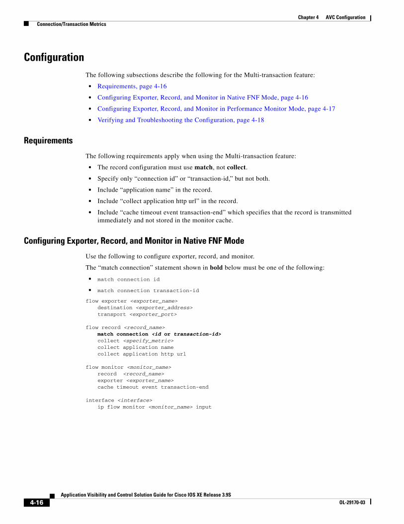
ConfigurationThe following subsections describe the following for the Multi-transaction feature:
• Requirements, page 4-16
• Configuring Exporter, Record, and Monitor in Native FNF Mode, page 4-16
• Configuring Exporter, Record, and Monitor in Performance Monitor Mode, page 4-17
• Verifying and Troubleshooting the Configuration, page 4-18
Requirements
The following requirements apply when using the Multi-transaction feature:
• The record configuration must use match, not collect.
• Specify only “connection id” or “transaction-id,” but not both.
• Include “application name” in the record.
• Include “collect application http url” in the record.
• Include “cache timeout event transaction-end” which specifies that the record is transmitted immediately and not stored in the monitor cache.
Configuring Exporter, Record, and Monitor in Native FNF Mode
Use the following to configure exporter, record, and monitor.
The “match connection” statement shown in bold below must be one of the following:
• match connection id
• match connection transaction-id
flow exporter <exporter_name>destination <exporter_address>transport <exporter_port>
flow record <record_name>match connection <id or transaction-id>collect <specify_metric>collect application namecollect application http url
flow monitor <monitor_name>record <record_name>exporter <exporter_name>cache timeout event transaction-end
interface <interface>ip flow monitor <monitor_name> input
4-16Application Visibility and Control Solution Guide for Cisco IOS XE Release 3.9S
OL-29170-03
Chapter 4 AVC Configuration Connection/Transaction Metrics
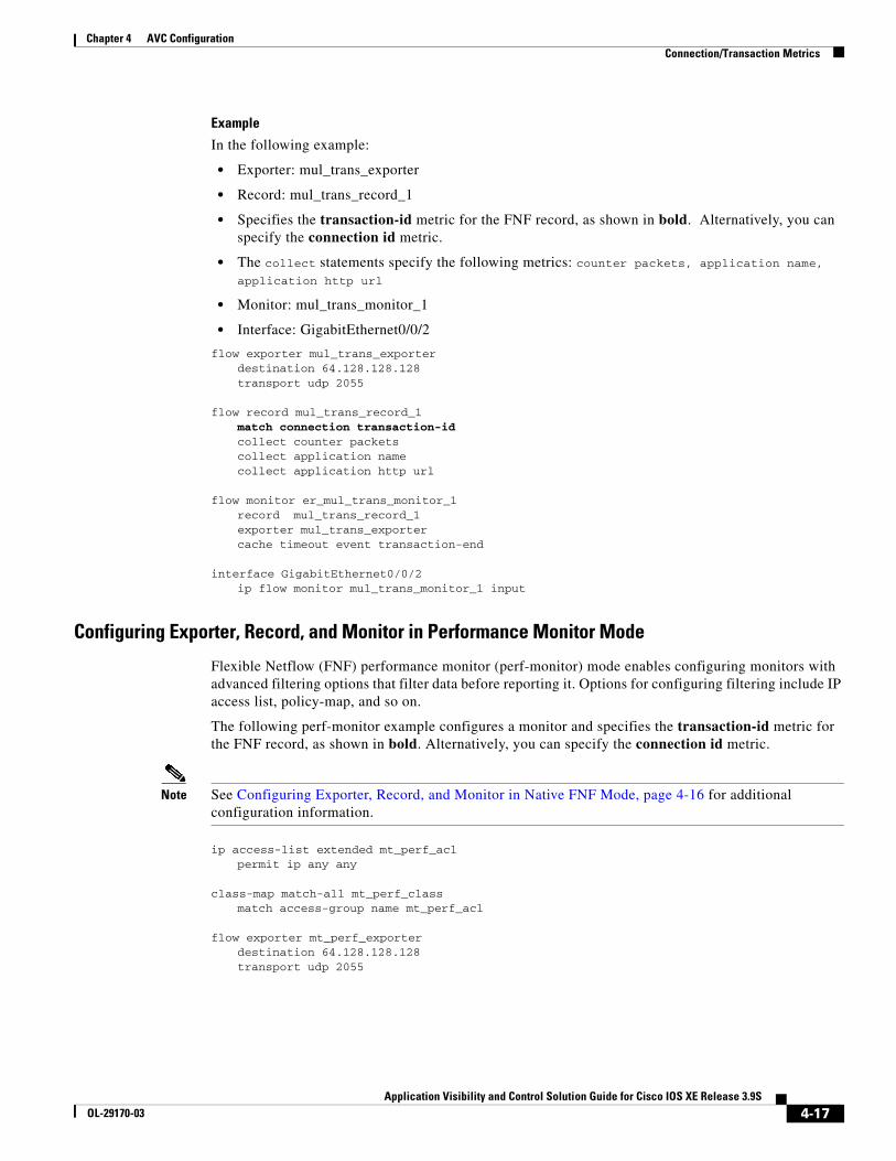
Example
In the following example:
• Exporter: mul_trans_exporter
• Record: mul_trans_record_1
• Specifies the transaction-id metric for the FNF record, as shown in bold. Alternatively, you can specify the connection id metric.
• The collect statements specify the following metrics: counter packets, application name, application http url
• Monitor: mul_trans_monitor_1
• Interface: GigabitEthernet0/0/2
flow exporter mul_trans_exporterdestination 64.128.128.128transport udp 2055
flow record mul_trans_record_1match connection transaction-idcollect counter packetscollect application namecollect application http url
flow monitor er_mul_trans_monitor_1record mul_trans_record_1exporter mul_trans_exportercache timeout event transaction-end
interface GigabitEthernet0/0/2ip flow monitor mul_trans_monitor_1 input
Configuring Exporter, Record, and Monitor in Performance Monitor Mode
Flexible Netflow (FNF) performance monitor (perf-monitor) mode enables configuring monitors with advanced filtering options that filter data before reporting it. Options for configuring filtering include IP access list, policy-map, and so on.
The following perf-monitor example configures a monitor and specifies the transaction-id metric for the FNF record, as shown in bold. Alternatively, you can specify the connection id metric.
Note See Configuring Exporter, Record, and Monitor in Native FNF Mode, page 4-16 for additional configuration information.
ip access-list extended mt_perf_aclpermit ip any any
class-map match-all mt_perf_classmatch access-group name mt_perf_acl
flow exporter mt_perf_exporterdestination 64.128.128.128transport udp 2055
4-17Application Visibility and Control Solution Guide for Cisco IOS XE Release 3.9S
OL-29170-03

Chapter 4 AVC Configuration Connection/Transaction Metrics
flow record type performance-monitor mt_perf_recordmatch connection transaction-idcollect counter packetscollect application namecollect application http url
flow monitor type performance-monitor mt_perf_monitorrecord mt_perf_recordexporter mt_perf_exportercache type normalcache timeout event transaction-end
policy-map type performance-monitor mt_perf_policyclass mt_perf_classflow monitor mt_perf_monitor
interface GigabitEthernet0/0/2service-policy type performance-monitor input mt_perf_policy
Verifying and Troubleshooting the Configuration
This section describes commands useful for verification and troubleshooting the FNF configuration. There are subsections for:
• Native or Performance Monitor Mode, page 4-18
• Native FNF Mode, page 4-18
• Performance Monitor Mode, page 4-19
Note For information about the show commands in the sections below, see the FNF command reference guide: http://www.cisco.com/en/US/docs/ios-xml/ios/fnetflow/command/fnf-cr-book.html
Native or Performance Monitor Mode
Verifying Multi-transaction Status
Display the Multi-transaction status:
show plat soft nbar statistics | inc is_multi_trs_enable
If Multi-transaction is enabled, the value is: is_multi_trs_enable==1
Native FNF Mode
Validating the Configuration
Use the following show commands to validate the configuration.
show flow exporter <exporter_name> templatesshow flow monitor <monitor_name>show platform hardware qfp active feature fnf client flowdef name <record_name>show platform hardware qfp active feature fnf client monitor name <monitor_name>
4-18Application Visibility and Control Solution Guide for Cisco IOS XE Release 3.9S
OL-29170-03

Chapter 4 AVC Configuration Configuration Examples
Viewing Collected FNF Data and Statistics
Use the following show commands to view the collected FNF data and statistics.
show flow monitor <monitor_name> cacheshow flow monitor <monitor_name> statisticsshow flow exporter <exporter_name> statisticsshow platform hardware qfp active feature fnf datapath aor
Performance Monitor Mode
Validating the Configuration
Use the following show commands to validate the configuration.
show flow exporter <exporter_name> templatesshow flow record type performance-monitor <record_name>show platform hardware qfp active feature fnf client monitor name <monitor_name>
Viewing Collected FNF Data and Statistics
Use the following show commands to view the FNF collected data and statistics.
show performance monitor cache monitor <monitor_name> detailshow flow exporter <exporter_name> statisticsshow platform hardware qfp active feature fnf datapath aor
Configuration ExamplesThis section contains configuration examples for the Cisco AVC solution. These examples provide a general view of a variety of configuration scenarios. Configuration is flexible and supports different types of record configurations.
Conversation Based Records—Omitting the Source PortThe monitor configured in the following example sends traffic reports based on conversation aggregation. For performance and scale reasons, it is preferable to send TCP performance metrics only for traffic that requires TCP performance measurements. It is recommended to configure two similar monitors:
• One monitor includes the required TCP performance metrics. In place of the line shown in bold in the example below (collect <any TCP performance metric>), include a line for each TCP metric for the monitor to collect.
• One monitor does not include TCP performance metrics.
The configuration is for IPv4 traffic. Similar monitors should be configured for IPv6.
flow record type performance-monitor conversation-recordmatch services waas segment account-on-resolutionmatch connection client ipv4 (or ipv6) address match connection server ipv4 (or ipv6) addressmatch connection server transport portmatch ipv4 (or ipv6) protocolmatch application name account-on-resolutioncollect interface inputcollect interface outputcollect connection server counter bytes longcollect connection client counter bytes longcollect connection server counter packets long
4-19Application Visibility and Control Solution Guide for Cisco IOS XE Release 3.9S
OL-29170-03

Chapter 4 AVC Configuration Configuration Examples
collect connection client counter packets longcollect connection sum-durationcollect connection new-connectionscollect policy qos class hierarchycollect policy qos queue idcollect <any TCP performance metric>
flow monitor type performance-monitor conversation-monitorrecord conversation-recordexporter my-exporterhistory size 0cache type synchronizedcache timeout synchronized 60cache entries <cache size>
HTTP URLThe monitor configured in the following example sends the HTTP host and URL. If the URL is not required, the host can be sent as part of the conversation record (see Conversation Based Records—Omitting the Source Port, page 4-19).
flow record type performance-monitor url-recordmatch transaction-id collect application namecollect connection client ipv4 (or ipv6) address collect routing vrf input collect application http url collect application http host<other metrics could be added here if needed. For example bytes/packets to calculate BW per URL Or performance metrics per URL>
flow monitor type url-monitor record url-recordexporter my-exporterhistory size 0cache type normalcache timeout event transaction-endcache entries <cache size>
Application Traffic Statistics The monitor configured in the following example collects application traffic statistics:
flow record type performance-monitor application-traffic-statsmatch ipv4 protocolmatch application name account-on-resolution match ipv4 versionmatch flow directioncollect connection initiatorcollect counter packetscollect counter bytes longcollect connection new-connectionscollect connection sum-duration
flow monitor type application-traffic-stats record application-traffic-statsexporter my-exporterhistory size 0
4-20Application Visibility and Control Solution Guide for Cisco IOS XE Release 3.9S
OL-29170-03

Chapter 4 AVC Configuration Configuration Examples
cache type synchronizedcache timeout synchronized 60cache entries <cache size>
Media RTP ReportThe monitor configured in the following example reports on media traffic:
flow record type performance-monitor media-recordmatch ipv4(or ipv6) protocolmatch ipv4(or ipv6) source address match ipv4(or ipv6) destination addressmatch transport source-portmatch transport destination-portmatch transport rtp ssrc match routing vrf inputcollect transport rtp payload-typecollect application namecollect counter packets longcollect counter bytes longcollect transport rtp jitter mean sumcollect transport rtp payload-typecollect <other media metrics>
flow monitor type media-monitor record media-recordexporter my-exporterhistory size 10 // default historycache type synchronizedcache timeout synchronized 60cache entries <cache size>
QoS Example 1: Control and Throttle TrafficThe following QoS configuration example illustrates how to control and throttle the peer-to-peer (P2P) traffic in the network to 1 megabit per second:
class-map match-all p2p-class-map match protocol attribute sub-category p2p-file-transfer
policy-map p2p-attribute-policy class p2p-class-map police 1000000interface Gig0/0/3 service-policy input p2p-attribute- policy
4-21Application Visibility and Control Solution Guide for Cisco IOS XE Release 3.9S
OL-29170-03

Chapter 4 AVC Configuration Configuration Examples
QoS Example 2: Assigning Priority and Allocating BandwidthThe following QoS configuration example illustrates how to allocate available bandwidth on the eth0/0 interface to different types of traffic. The allocations are as follows:
• Business-critical Citrix application traffic for “access-group 101” users receives highest priority, with 50% of available bandwidth committed and traffic assigned to a priority queue. The police statement limits the bandwidth of business-critical traffic to 50% in the example.
• Web browsing receives a committed 30% of the remaining bandwidth after the business-critical traffic. This is a commitment of 15% of the total bandwidth available on the interface.
• Internal browsing, as defined by a specific domain (myserver.com in the example), receives a committed 60% of the browsing bandwidth.
• All remaining traffic uses the remaining 35% of the total bandwidth.
The policy statements commit minimum bandwidth in the percentages described for situations of congestion. When bandwidth is available, traffic can receive more than the “committed” amount. For example, if there is no business-critical traffic at a given time, more bandwidth is available to browsing and other traffic.
Figure 4-3 illustrates the priority and bandwidth allocation for each class. “Remaining traffic” refers to all traffic not specifically defined by the class mapping.
Figure 4-3 Bandwidth allocation
4-22Application Visibility and Control Solution Guide for Cisco IOS XE Release 3.9S
OL-29170-03

Chapter 4 AVC Configuration Configuration Examples
In class-map definition statements:
• match-all restricts the definition to traffic meeting all of the “match” conditions that follow. For example, the “business-critical” class only includes Citrix protocol traffic from IP addresses in “access-group 101.”
• match-any includes traffic meeting one or more of the “match” conditions that follow.
class-map match-all business-criticalmatch protocol citrixmatch access-group 101
class-map match-any browsingmatch protocol attribute category browsing
class-map match-any internal-browsing
match protocol http url “*myserver.com*” policy-map internal-browsing-policy
class internal-browsingbandwidth remaining percent 60
policy-map my-network-policy
class business-criticalprioritypolice cir percent 50
class browsingbandwidth remaining percent 30service-policy internal-browsing-policy
interface eth0/0
service-policy output my-network-policy
4-23Application Visibility and Control Solution Guide for Cisco IOS XE Release 3.9S
OL-29170-03

Chapter 4 AVC Configuration Configuration Examples
4-24Application Visibility and Control Solution Guide for Cisco IOS XE Release 3.9S
OL-29170-03

Application Visibility and COL-29170-03
C H A P T E R 5
TroubleshootingRevised: August 14, 2013, OL-29170-03
This troubleshooting section includes the following topics:
• Report Is Not Displayed Correctly, page 5-1
• Incorrect TCP Performance Statistics, page 5-2
• FNF Memory Warning, page 5-3
• More Than 32 Matches per Class, page 5-3
• More Than Five Monitors per Class, page 5-4
Report Is Not Displayed CorrectlyThe following may be helpful for troubleshooting a report that is not displayed correctly:
• Verify that your flow exporter is configured with the correct destination IP.
• If you are using a VRF, ensure that it is added at the destination.
(config-flow-exporter)#destination 1.1.1.1 vrf myVrf
• Check whether samplers are configured correctly.
• Check the flow exporter statistics for errors.
# show flow exporter statistics Flow Exporter my_exporter: Packet send statistics (last cleared 4d00h ago): Successfully sent: 203808 (280136412 bytes) Client send statistics: Client: Option options interface-table Records added: 18528 - sent: 18528 Bytes added: 1852800 - sent: 1852800 Client: Option options vrf-id-name-table Records added: 3474 - sent: 3474 Bytes added: 125064 - sent: 125064 Client: Option options sampler-table Records added: 0 Bytes added: 0
5-1ontrol Solution Guide for Cisco IOS XE Release 3.9S

Chapter 5 Troubleshooting
Client: Option options application-name Records added: 1213584
• Check the cache output and verify that the specific monitor is not empty.
# show performance monitor cache detail [format record]
• Verify policy and class-map hits (counters should increase).
# show policy-map type performance-monitor interface g0/0/2 GigabitEthernet0/0/2 Service-policy performance-monitor input: mymon_in Class-map: select_ipv4_tcpperf (match-all) 354704 packets, 75729623 bytes 30 second offered rate 1000 bps, drop rate 0000 bps Match: protocol ip Match: access-group name ipv4_tcpperf Class-map: class-default (match-any) 0 packets, 0 bytes 30 second offered rate 0000 bps, drop rate 0000 bps Match: any
• Review the running-config and verify that nothing is missing or misconfigured. The problem can be caused by even a single access-list missing.
• Verify that account-on-resolution (AOR) is active.
– If AOR is active, handles will have a non-zero value, as shown in the following example:
# show platform hardware qfp active feature fnf datapath aor CFT: ConfigAddress 0x8a1e16a0, Instance 0x8a1de760, Feat ID 1, FlowObj ID 1 CVLA: handle 0x97f00000 epoch 0x4
– If AOR is inactive, handles will have the value of zero, as shown in the following example:
# show platform hardware qfp active feature fnf datapath aor CFT: ConfigAddress 0x8a1e16a0, Instance 0x00000000, Feat ID 0, FlowObj ID 0 CVLA: handle 0x0 epoch 0x4
Incorrect TCP Performance StatisticsThe following may be helpful for troubleshooting incorrect TCP performance statistics:
• Verify that the monitor that includes TCP performance metrics is applied to only one interface.
• For that interface, service-policy must be attached in both directions.
• Check for asymmetric routing.
• Verify that routes/route-maps are configured correctly.
• If filtering applications, ensure that the appropriate class-map has hits.
• Verify that account-on-resolution (AOR) is active. For details about verifying AOR, see Report Is Not Displayed Correctly, page 5-1.
• Enable IP NBAR Protocol Discovery on the interface to determine whether the protocol of interest is identified.
Router(config-if)# ip nbar protocol-discoveryRouter# show ip nbar protocol-discovery interface g0/0/3
5-2Application Visibility and Control Solution Guide for Cisco IOS XE Release 3.9S
OL-29170-03

Chapter 5 Troubleshooting
GigabitEthernet0/0/3 Last clearing of "show ip nbar protocol-discovery" counters 00:00:10 Input Output ----- ------ Protocol Packet Count Packet Count Byte Count Byte Count 30sec Bit Rate (bps) 30sec Bit Rate (bps) 30sec Max Bit Rate (bps) 30sec Max Bit Rate (bps) ------------------------ ------------------------ ------------------------ http 7 8 3472 1740 0 0 0 0
FNF Memory WarningThe following type of error message typically occurs if the total memory consumed by all monitors exceeds 25% of the total available memory:
Oct 28 14:44:10.358 IST: %QFP_FNF-4-FNF_MEM_UPLIMIT_WARN: F0: cpp_cp: Netflow and Flexible Netflow configuration is using (140199440) bytes of data plane DRAM which exceeds the recommended maximum of (134217728) bytes.
This warning message indicates that a large amount of memory is allocated to Flexible NetFlow (FNF) monitors. Allocating this amount of memory to FNF monitors is acceptable, but the total memory required by all other enabled features must not exceed the available memory. If the memory required for all enabled features exceeds the memory available, the following may be helpful for troubleshooting:
• Review the configuration. If there are mismatches, remove the configuration and reapply it.
• Reduce the FNF monitor cache size.
More Than 32 Matches per ClassThe following may be helpful for troubleshooting the following type of error message regarding configuring more than 32 matching statements:
cannot configure more than 32 matching statements per class-map for the interface
• Review your class-map configuration.
# show class-map
• Make sure every class-map has no more than 32 match instructions, including hierarchical classes. Remove redundant match instructions
5-3Application Visibility and Control Solution Guide for Cisco IOS XE Release 3.9S
OL-29170-03
Chapter 5 Troubleshooting
More Than Five Monitors per ClassThe following may be helpful if you receive the following type of error message regarding the limit of five (5) monitors per policy per class:
%Only 5 monitors allowed per policy per class
• Review the class-map configuration.
# show class-map
• Verify that every class-map has no more than five monitors, including FNF monitors which are applied directly on the interface. Remove any redundant monitors and retry.
5-4Application Visibility and Control Solution Guide for Cisco IOS XE Release 3.9S
OL-29170-03

Application Visibility and Control SOL-29170-03
A
P P E N D I X A
AVC Supported Platforms and InterfacesRevised: August 14, 2013, OL-29170-03
This chapter addresses the following topics:
• AVC Supported Platforms, page A-1
• AVC Supported Interfaces, page A-1
AVC Supported PlatformsCisco AVC is supported on the following platforms:
• Cisco ASR1000 Series Aggregation Services Routers
• Cisco CSR 1000V Cloud Services Routers
AVC Supported InterfacesTable A-1 describes the interfaces that Cisco AVC supports in the current release.
Table A-1 AVC supported interfaces
Interface Visibility QoS Notes
Ether/Port Channel Yes No
Gig Yes Yes
GRE mGRE1
Yes Yes Tunnels are supported only on terminating devices.
QoS only supports output direction.
mGRE is not supported with IPv6.
IPSEC2 DMVPN3
Yes Yes Tunnels are supported only on terminating devices.
QoS only supports output direction.
Pure IPv6 is not supported with these tunnels.
IPv6 Yes Yes
MLFR4 Yes Yes
A-1olution Guide for Cisco IOS XE Release 3.9S

Appendix A AVC Supported Platforms and Interfaces AVC Supported Interfaces
MLPPP5 Yes Yes
Pass Through Tunneled IPv6
No Yes
POS6/ATM7 Yes Yes
PPP8 No Yes Tunnels are supported only on terminating devices.
Sub Interface Yes Yes
VASI9 Yes Yes
VRF10
VLAN11
Yes Yes
1. GRE = Generic Routing Encapsulation, mGRE = Multipoint Generic Routing Encapsulation
2. IPSEC = IP Security
3. DMVPN = Dynamic Multipoint Virtual Private Network
4. MLFR = Multilink Frame Relay
5. MLPPP = Multilink PPP (also referred to as MP, MPPP, and MLP)
6. POS = Packet over SONET (SONET = Synchronous Optical Network)
7. ATM = Asynchronous Transfer Mode
8. PPP = Point-to-Point Protocol
9. VASI = VRF-Aware Service Infrastructure
10. VRF = Virtual Routing and Forwarding
11. VLAN = Virtual LAN
Interface Visibility QoS Notes
A-2Application Visibility and Control Solution Guide for Cisco IOS XE Release 3.9S
OL-29170-03

Application Visibility and Control SOL-29170-03
A
P P E N D I X B New Exported FieldsRevised: August 14, 2013, OL-29170-03
Table B-1 describes the Flexible NetFlow (FNF) fields and the CLI used to retrieve the value of the fields, added for Cisco AVC for IOS XE 3.8 and 3.9.
In addition to the these new fields, an AVC record can include FNF fields defined prior to IOS XE 3.8. For information about FNF fields, see: Cisco IOS Flexible NetFlow Command Reference.
Table B-1 New FNF Exported Fields
Field ID Name
EnterpriseSpecific Data Type
Data TypeSemantics Description Units CLI
56 sourceMacAddress No macAddress identifier IEEE 802 source MAC address field. This field is collected only for a monitor attached in the ingress direc-tion.
MAC <collect | match> datalink mac source address input
57 postDestinationMacAddress
No macAddress identifier The definition of this infor-mation element is identical to the definition of information element “destinationMacAd-dress,” except that it reports a potentially modified value caused by a middlebox func-tion after the packet has passed the observation point.
MAC <collect | match> datalink mac desti-nation address out-put
58 vlanId No unsigned16 identifier IEEE 802.1Q VLAN identi-fier (VID) extracted from the tag control Information field that was attached to the IP packet.This field is collected only for a monitor attached in the ingress direction.
number <collect | match> datalink source-vlan-id
B-1olution Guide for Cisco IOS XE Release 3.9S

Appendix B New Exported Fields
59 postVlanId No unsigned16 identifier The definition of this infor-mation element is identical to the definition of information element “vlanId,” except that it reports a potentially modi-fied value caused by a mid-dlebox function after the packet has passed the obser-vation point.
number <collect | match> datalink destina-tion-vlan-id
80 destinationMacAddress
No macAddress identifier IEEE 802 destination MAC address field. This field is collected only for a monitor attached in the ingress direc-tion.
MAC <collect | match> datalink mac desti-nation address input
81 postSourceMacAddress
No macAddress identifier The definition of this infor-mation element is identical to the definition of information element “sourceMacAd-dress,” except that it reports a potentially modified value caused by a middlebox func-tion after the packet has passed the observation point.
MAC <collect | match> datalink mac source address output
209 tcpOptions No unsigned64 flags TCP options in packets of this flow. The information is encoded in a set of bit fields. For each TCP option, there is a bit in this set. The bit is set to 1 if any observed packet of this flow contains the corre-sponding TCP option. Other-wise, if no observed packet of this flow contained the respective TCP option, the value of the corresponding bit is 0.
bitmap collect transport tcp option map
231 initiatorOctets No unsigned64 identifier Total number of layer 4 pay-load bytes in a flow from the initiator. The initiator is the device that triggered the ses-sion creation, and remains the same for the life of the ses-sion.
octets collect counter ini-tiator bytes long
232 serverOctets No unsigned64 identifier Total number of layer 4 pay-load bytes in a flow from the server. The server is the device that replies to the client, and remains the same for the life of the session.
octets collect connection server counter bytes long
Field ID Name
EnterpriseSpecific Data Type
Data TypeSemantics Description Units CLI
B-2Application Visibility and Control Solution Guide for Cisco IOS XE Release 3.9S
OL-29170-03
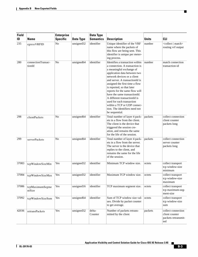
Appendix B New Exported Fields
235 egressVRFID No unsigned32 identifier Unique identifier of the VRF name where the packets of this flow are being sent. This identifier is unique per meter-ing process.
number <collect | match> routing vrf output
280 connectionTransac-tionId
No unsigned64 identifier Identifies a transaction within a connection. A transaction is a meaningful exchange of application data between two network devices or a client and server. A transactionId is assigned the first time a flow is reported, so that later reports for the same flow will have the same transactionId. A different transactionId is used for each transaction within a TCP or UDP connec-tion. The identifiers need not be sequential.
number match connection transaction-id
298 clientPackets No unsigned64 identifier Total number of layer 4 pack-ets in a flow from the client. The client is the device that triggered the session cre-ation, and remains the same for the life of the session.
packets collect connection client counter packets long
299 serverPackets No unsigned64 identifier Total number of layer 4 pack-ets in a flow from the server. The server is the device that replies to the client, and remains the same for the life of the session.
packets collect connection server counter packets long
37083 tcpWindowSizeMin Yes unsigned32 identifier Minimum TCP window size. octets collect transport tcp window-size minimum
37084 tcpWindowSizeMax Yes unsigned32 identifier Maximum TCP window size. octets collect transport tcp window-size maximum
37086 tcpMaximumSegmentSize
Yes unsigned16 identifier TCP maximum segment size. octets collect transport tcp maximum-seg-ment-size
37092 tcpWindowSizeSum Yes unsigned64 identifier Sum of TCP window size val-ues. Divide by packet counter to get average.
octets collect transport tcp window-size sum
42036 retransPackets Yes unsigned32 delta-Counter
Number of packets retrans-mitted by the client
packets collect connection client counter packets retransmit-ted
Field ID Name
EnterpriseSpecific Data Type
Data TypeSemantics Description Units CLI
B-3Application Visibility and Control Solution Guide for Cisco IOS XE Release 3.9S
OL-29170-03
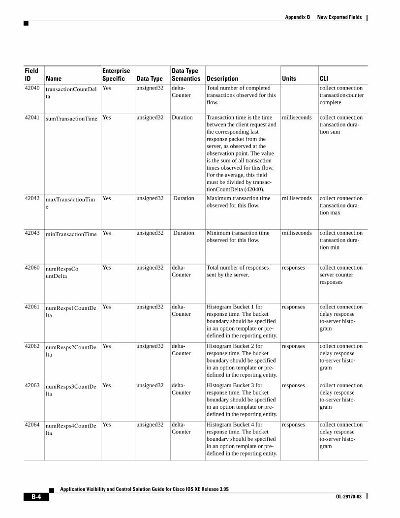
Appendix B New Exported Fields
42040 transactionCountDelta
Yes unsigned32 delta-Counter
Total number of completed transactions observed for this flow.
collect connection transaction counter complete
42041 sumTransactionTime Yes unsigned32 Duration Transaction time is the time between the client request and the corresponding last response packet from the server, as observed at the observation point. The value is the sum of all transaction times observed for this flow.For the average, this field must be divided by transac-tionCountDelta (42040).
milliseconds collect connection transaction dura-tion sum
42042 maxTransactionTime
Yes unsigned32 Duration Maximum transaction time observed for this flow.
milliseconds collect connection transaction dura-tion max
42043 minTransactionTime Yes unsigned32 Duration Minimum transaction time observed for this flow.
milliseconds collect connection transaction dura-tion min
42060 numRespsCo untDelta
Yes unsigned32 delta-Counter
Total number of responses sent by the server.
responses collect connection server counter responses
42061 numResps1CountDelta
Yes unsigned32 delta-Counter
Histogram Bucket 1 for response time. The bucket boundary should be specified in an option template or pre-defined in the reporting entity.
responses collect connection delay response to-server histo-gram
42062 numResps2CountDelta
Yes unsigned32 delta-Counter
Histogram Bucket 2 for response time. The bucket boundary should be specified in an option template or pre-defined in the reporting entity.
responses collect connection delay response to-server histo-gram
42063 numResps3CountDelta
Yes unsigned32 delta-Counter
Histogram Bucket 3 for response time. The bucket boundary should be specified in an option template or pre-defined in the reporting entity.
responses collect connection delay response to-server histo-gram
42064 numResps4CountDelta
Yes unsigned32 delta-Counter
Histogram Bucket 4 for response time. The bucket boundary should be specified in an option template or pre-defined in the reporting entity.
responses collect connection delay response to-server histo-gram
Field ID Name
EnterpriseSpecific Data Type
Data TypeSemantics Description Units CLI
B-4Application Visibility and Control Solution Guide for Cisco IOS XE Release 3.9S
OL-29170-03

Appendix B New Exported Fields
42065 numResps5CountDelta
Yes unsigned32 delta-Counter
Histogram Bucket 5 for response time. The bucket boundary should be specified in an option template or pre-defined in the reporting entity.
responses collect connection delay response to-server histo-gram
42066 numResps6CountDelta
Yes unsigned32 delta-Counter
Histogram Bucket 6 for response time. The bucket boundary should be specified in an option template or pre-defined in the reporting entity.
responses collect connection delay response to-server histo-gram
42067 numResps7CountDelta
Yes unsigned32 delta-Counter
Histogram Bucket 7 for response time. The bucket boundary should be specified in an option template or pre-defined in the reporting entity.
responses collect connection delay response to-server histo-gram
42068 numLateRespsCountDelta
Yes unsigned32 delta-Counter
Total number of late responses sent by the server. A late response is a response whose time is greater than the last bucket. This informa-tional element can be treated as the last bucket that has no end limit.
responses collect connection delay response to-server histo-gram
42071 sumRespTime Yes unsigned32 Delay Response time is the time between the client request and the corresponding first response packet from the server, as observed at the observation point. The value of this information element is the sum of all response times observed for the responses of this flow. For the average, this field must be divided by num-RespsCountDelta (42060).
milliseconds collect connection delay response to-server sum
42072 maxRespTime Yes unsigned32 Delay Maximum response time observed for this flow.
milliseconds collect connection delay response to-server max
42073 minRespTime Yes unsigned32 Delay Minimum response time observed for this flow.
milliseconds collect connection delay response to-server min
42074 sumServerRespTime Yes unsigned32 Delay Yes milliseconds collect connection delay application sum
Field ID Name
EnterpriseSpecific Data Type
Data TypeSemantics Description Units CLI
B-5Application Visibility and Control Solution Guide for Cisco IOS XE Release 3.9S
OL-29170-03
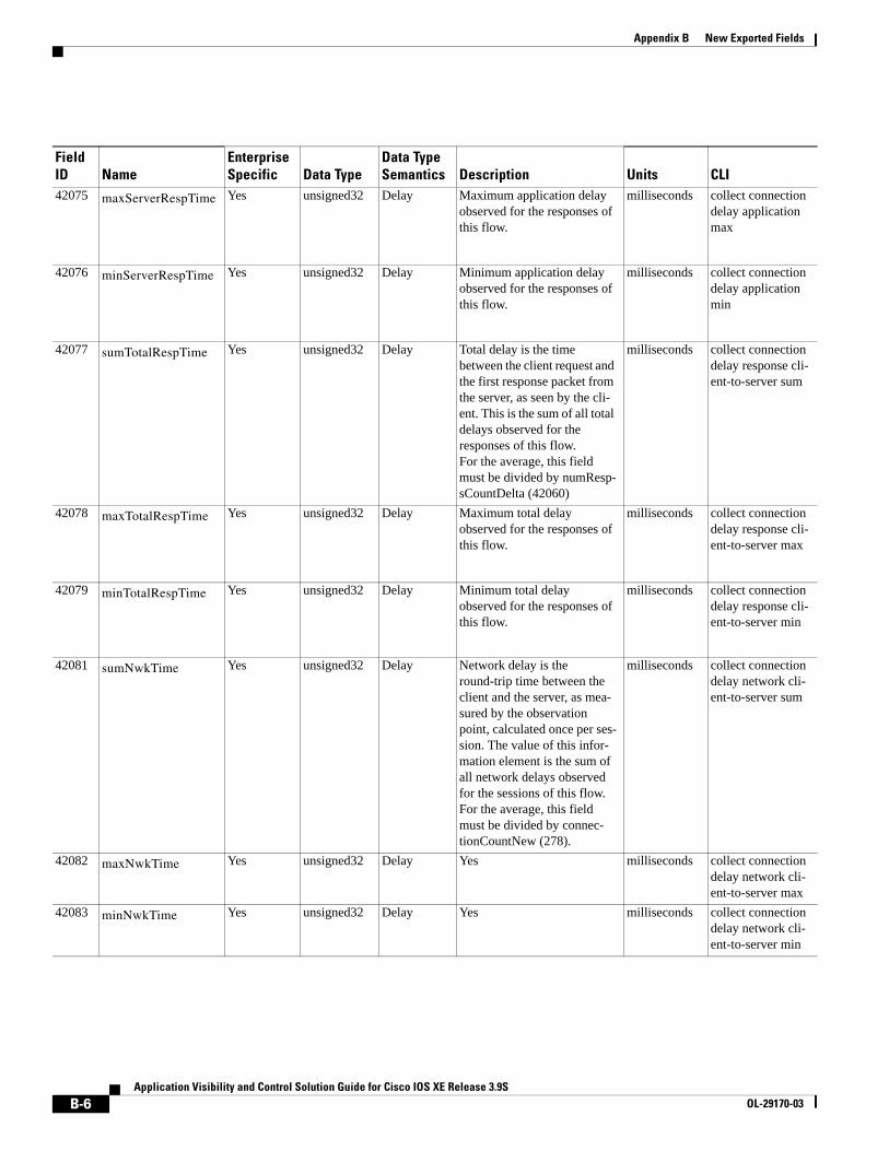
Appendix B New Exported Fields
42075 maxServerRespTime Yes unsigned32 Delay Maximum application delay observed for the responses of this flow.
milliseconds collect connection delay application max
42076 minServerRespTime Yes unsigned32 Delay Minimum application delay observed for the responses of this flow.
milliseconds collect connection delay application min
42077 sumTotalRespTime Yes unsigned32 Delay Total delay is the time between the client request and the first response packet from the server, as seen by the cli-ent. This is the sum of all total delays observed for the responses of this flow.For the average, this field must be divided by numResp-sCountDelta (42060)
milliseconds collect connection delay response cli-ent-to-server sum
42078 maxTotalRespTime Yes unsigned32 Delay Maximum total delay observed for the responses of this flow.
milliseconds collect connection delay response cli-ent-to-server max
42079 minTotalRespTime Yes unsigned32 Delay Minimum total delay observed for the responses of this flow.
milliseconds collect connection delay response cli-ent-to-server min
42081 sumNwkTime Yes unsigned32 Delay Network delay is the round-trip time between the client and the server, as mea-sured by the observation point, calculated once per ses-sion. The value of this infor-mation element is the sum of all network delays observed for the sessions of this flow.For the average, this field must be divided by connec-tionCountNew (278).
milliseconds collect connection delay network cli-ent-to-server sum
42082 maxNwkTime Yes unsigned32 Delay Yes milliseconds collect connection delay network cli-ent-to-server max
42083 minNwkTime Yes unsigned32 Delay Yes milliseconds collect connection delay network cli-ent-to-server min
Field ID Name
EnterpriseSpecific Data Type
Data TypeSemantics Description Units CLI
B-6Application Visibility and Control Solution Guide for Cisco IOS XE Release 3.9S
OL-29170-03
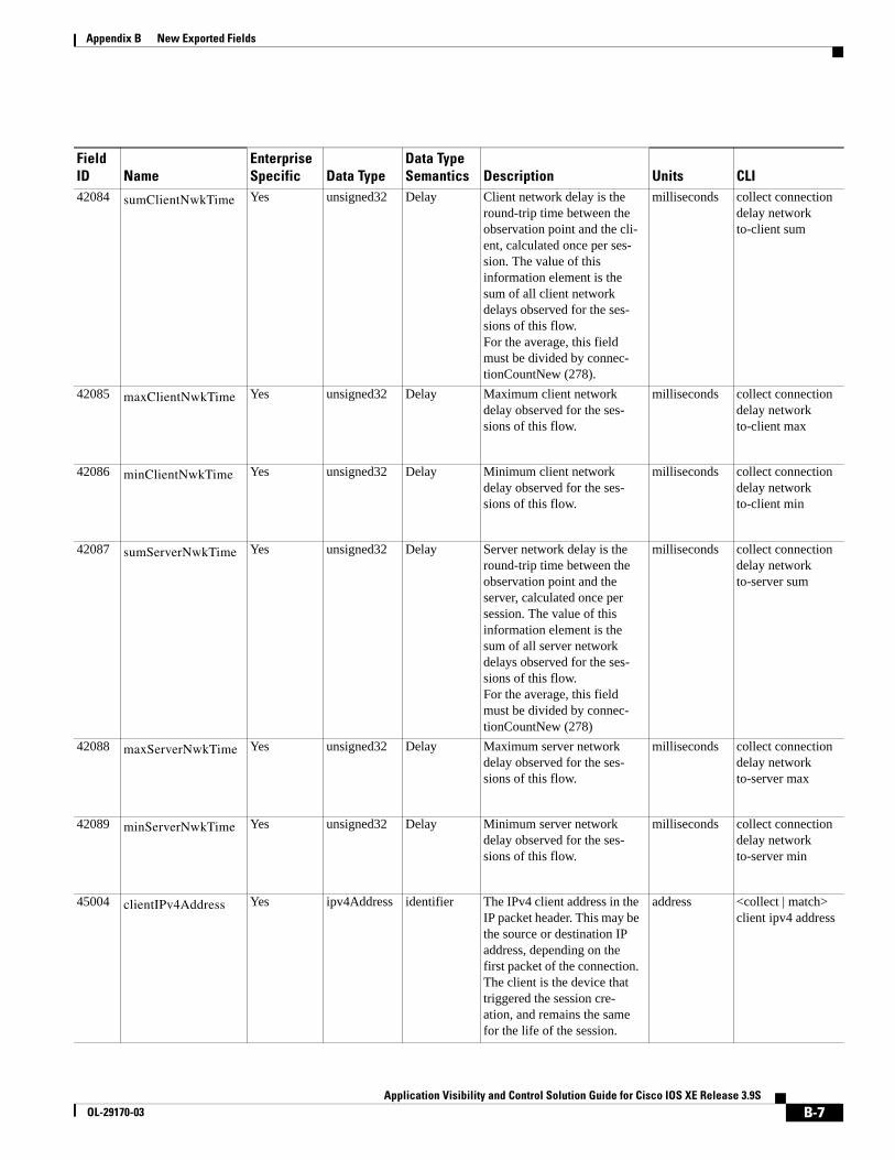
Appendix B New Exported Fields
42084 sumClientNwkTime Yes unsigned32 Delay Client network delay is the round-trip time between the observation point and the cli-ent, calculated once per ses-sion. The value of this information element is the sum of all client network delays observed for the ses-sions of this flow.For the average, this field must be divided by connec-tionCountNew (278).
milliseconds collect connection delay network to-client sum
42085 maxClientNwkTime Yes unsigned32 Delay Maximum client network delay observed for the ses-sions of this flow.
milliseconds collect connection delay network to-client max
42086 minClientNwkTime Yes unsigned32 Delay Minimum client network delay observed for the ses-sions of this flow.
milliseconds collect connection delay network to-client min
42087 sumServerNwkTime Yes unsigned32 Delay Server network delay is the round-trip time between the observation point and the server, calculated once per session. The value of this information element is the sum of all server network delays observed for the ses-sions of this flow. For the average, this field must be divided by connec-tionCountNew (278)
milliseconds collect connection delay network to-server sum
42088 maxServerNwkTime Yes unsigned32 Delay Maximum server network delay observed for the ses-sions of this flow.
milliseconds collect connection delay network to-server max
42089 minServerNwkTime Yes unsigned32 Delay Minimum server network delay observed for the ses-sions of this flow.
milliseconds collect connection delay network to-server min
45004 clientIPv4Address Yes ipv4Address identifier The IPv4 client address in the IP packet header. This may be the source or destination IP address, depending on the first packet of the connection. The client is the device that triggered the session cre-ation, and remains the same for the life of the session.
address <collect | match> client ipv4 address
Field ID Name
EnterpriseSpecific Data Type
Data TypeSemantics Description Units CLI
B-7Application Visibility and Control Solution Guide for Cisco IOS XE Release 3.9S
OL-29170-03

Appendix B New Exported Fields
45005 serverIPv4Address Yes ipv4Address identifier The IPv4 server address in the IP packet header. The server is the device that replies to the client, and remains the same for the life of the session.
address <collect | match> server ipv4 address
45006 clientIPv6Address Yes ipv6Address identifier The IPv6 client address in the IP packet header. The client is the device that triggered the session creation, and remains the same for the life of the session.
address <collect | match> client ipv6 address
45007 serverIPv6Address Yes ipv6address identifier IPv6 server address in the IP packer header. The server is the device that replies to the client, and remains the same for the life of the session.
address <collect | match> server ipv6 address
45008 clientTransportPort Yes unsigned16 identifier Client transport port identi-fier. This may be the source or destination transport port. The client is the device that triggered the session cre-ation, and remains the same for the life of the session.
number <collect | match> client transport port
45009 serverTransportPort Yes unsigned16 identifier Server transport port identi-fier. This may be the source or destination transport port. The server is the device that replies to the client, and remains the same for the life of the session.
number <collect | match> server transport port
41000 classHierarchy Yes Var-Len identifier Identifies the policy-map hierarchy for different pol-icy-map types. The field con-tains the policy-id, followed by a list of classes represent-ing the policy hierarchy: {Pi | Ck … Cl}. A dedicated option template contains the policy and class id mapping to name and type.
number <collect | match> policy perfor-mance-monitor classification hier-archy
Field ID Name
EnterpriseSpecific Data Type
Data TypeSemantics Description Units CLI
B-8Application Visibility and Control Solution Guide for Cisco IOS XE Release 3.9S
OL-29170-03
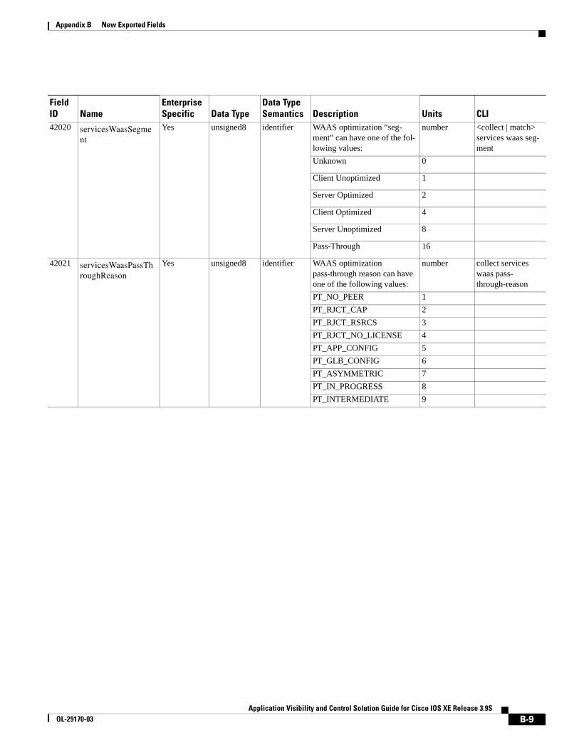
Appendix B New Exported Fields
42020 servicesWaasSegment
Yes unsigned8 identifier WAAS optimization “seg-ment” can have one of the fol-lowing values:
number <collect | match> services waas seg-ment
Unknown 0
Client Unoptimized 1
Server Optimized 2
Client Optimized 4
Server Unoptimized 8
Pass-Through 16
42021 servicesWaasPassThroughReason
Yes unsigned8 identifier WAAS optimization pass-through reason can have one of the following values:
number collect services waas pass-through-reason
PT_NO_PEER 1PT_RJCT_CAP 2PT_RJCT_RSRCS 3PT_RJCT_NO_LICENSE 4PT_APP_CONFIG 5PT_GLB_CONFIG 6PT_ASYMMETRIC 7PT_IN_PROGRESS 8PT_INTERMEDIATE 9
Field ID Name
EnterpriseSpecific Data Type
Data TypeSemantics Description Units CLI
B-9Application Visibility and Control Solution Guide for Cisco IOS XE Release 3.9S
OL-29170-03
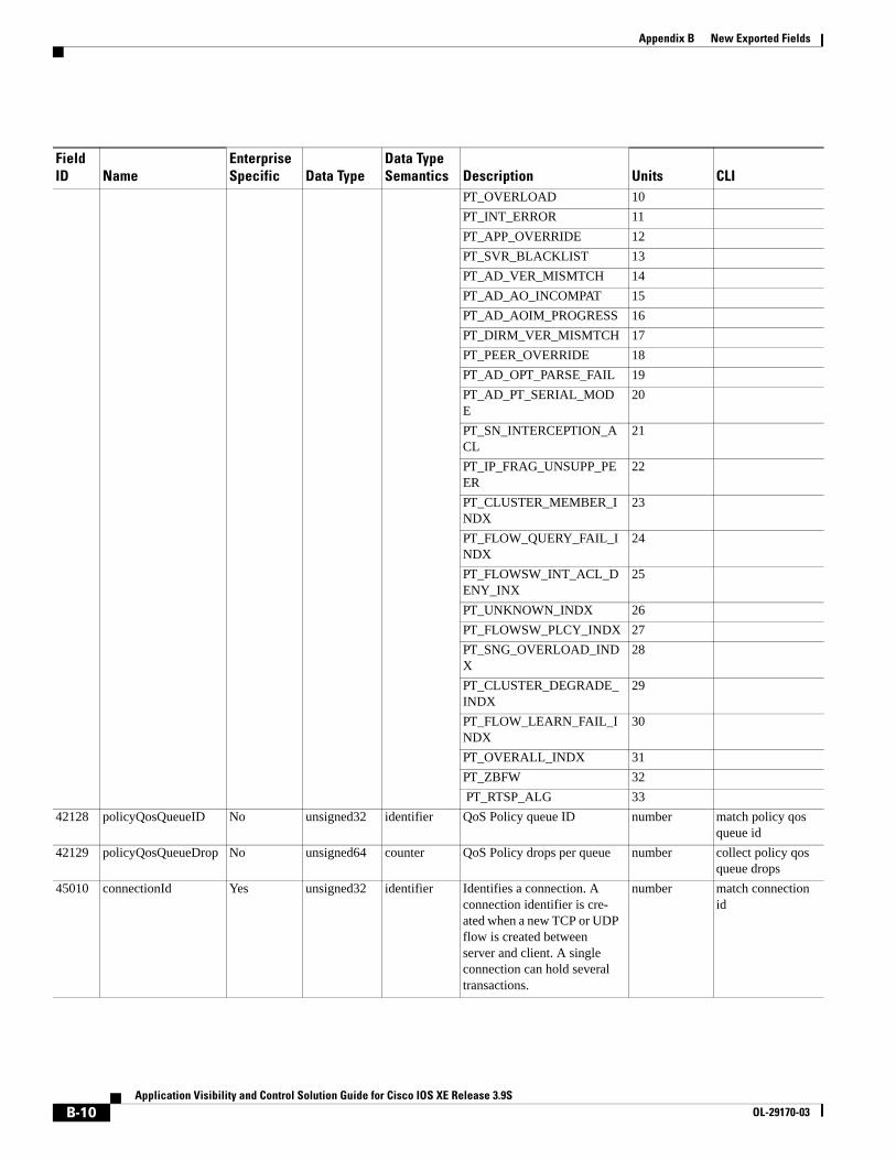
Appendix B New Exported Fields
PT_OVERLOAD 10PT_INT_ERROR 11PT_APP_OVERRIDE 12PT_SVR_BLACKLIST 13PT_AD_VER_MISMTCH 14PT_AD_AO_INCOMPAT 15PT_AD_AOIM_PROGRESS 16PT_DIRM_VER_MISMTCH 17PT_PEER_OVERRIDE 18PT_AD_OPT_PARSE_FAIL 19PT_AD_PT_SERIAL_MODE
20
PT_SN_INTERCEPTION_ACL
21
PT_IP_FRAG_UNSUPP_PEER
22
PT_CLUSTER_MEMBER_INDX
23
PT_FLOW_QUERY_FAIL_INDX
24
PT_FLOWSW_INT_ACL_DENY_INX
25
PT_UNKNOWN_INDX 26PT_FLOWSW_PLCY_INDX 27PT_SNG_OVERLOAD_INDX
28
PT_CLUSTER_DEGRADE_INDX
29
PT_FLOW_LEARN_FAIL_INDX
30
PT_OVERALL_INDX 31PT_ZBFW 32 PT_RTSP_ALG 33
42128 policyQosQueueID No unsigned32 identifier QoS Policy queue ID number match policy qos queue id
42129 policyQosQueueDrop No unsigned64 counter QoS Policy drops per queue number collect policy qos queue drops
45010 connectionId Yes unsigned32 identifier Identifies a connection. A connection identifier is cre-ated when a new TCP or UDP flow is created between server and client. A single connection can hold several transactions.
number match connection id
Field ID Name
EnterpriseSpecific Data Type
Data TypeSemantics Description Units CLI
B-10Application Visibility and Control Solution Guide for Cisco IOS XE Release 3.9S
OL-29170-03
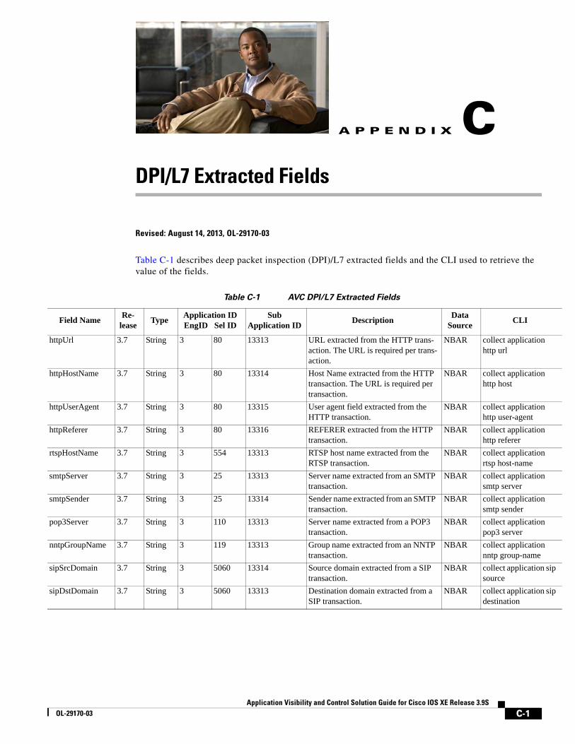
Application Visibility and Control SOL-29170-03
A
P P E N D I X Cp
p
DPI/L7 Extracted Fields
Revised: August 14, 2013, OL-29170-03
Table C-1 describes deep packet inspection (DPI)/L7 extracted fields and the CLI used to retrieve the value of the fields.
Table C-1 AVC DPI/L7 Extracted Fields
Field Name Re- lease Type Application ID
EngID Sel IDSub
Application ID Description Data Source CLI
httpUrl 3.7 String 3 80 13313 URL extracted from the HTTP trans-action. The URL is required per trans-action.
NBAR collect application http url
httpHostName 3.7 String 3 80 13314 Host Name extracted from the HTTP transaction. The URL is required per transaction.
NBAR collect application http host
httpUserAgent 3.7 String 3 80 13315 User agent field extracted from the HTTP transaction.
NBAR collect application http user-agent
httpReferer 3.7 String 3 80 13316 REFERER extracted from the HTTP transaction.
NBAR collect application http referer
rtspHostName 3.7 String 3 554 13313 RTSP host name extracted from the RTSP transaction.
NBAR collect application rtsp host-name
smtpServer 3.7 String 3 25 13313 Server name extracted from an SMTP transaction.
NBAR collect application smtp server
smtpSender 3.7 String 3 25 13314 Sender name extracted from an SMTP transaction.
NBAR collect application smtp sender
pop3Server 3.7 String 3 110 13313 Server name extracted from a POP3 transaction.
NBAR collect application pop3 server
nntpGroupName 3.7 String 3 119 13313 Group name extracted from an NNTP transaction.
NBAR collect application nntp group-name
sipSrcDomain 3.7 String 3 5060 13314 Source domain extracted from a SIP transaction.
NBAR collect application sisource
sipDstDomain 3.7 String 3 5060 13313 Destination domain extracted from a SIP transaction.
NBAR collect application sidestination
C-1olution Guide for Cisco IOS XE Release 3.9S

Appendix C DPI/L7 Extracted Fields
Notes
• Beginning with IOS XE release 3.7, the fields are exported using the field subApplicationValue (ID=45003). The field is encoded as {applicationID (4B), subApplicationID (2B), Value (Variable Len)} merged together. If the field is not observed, the size of the field is 6 and includes only applicationTag and subApplicationTag.
• The sub-application-table option template maps the extracted field ID to name and description, as follows:
– Extracted field ID: subApplicationTag (ID=97)
– Name: subApplicationName (ID=109)
– Description: subApplicationDesc (ID=110)
• All HTTP-based applications, such as YouTube, SharePoint, and so on, use the same sub-application ID, defined by the subApplicationID, as defined by the HTTP application.
C-2Application Visibility and Control Solution Guide for Cisco IOS XE Release 3.9S
OL-29170-03

Application Visibility and Control SOL-29170-03
A
P P E N D I X D Fields that Require Punt to the Route ProcessorRevised: August 14, 2013, OL-29170-03
Table D-1 describes the media monitoring/metadata metrics that require punt to the route processor (RP).
Table D-1 Media Monitoring/Metadata Metric Fields
Metric NetFlow ID
Media Monitoring related fields
collect counter flows 3
collect application media bytes rate 37006
collect application media packets rate 37009
collect application media packets rate variation 37010
collect application media event 37011
collect monitor event 37012
collect timestamp interval 37013
collect transport packets lost rate 37021
collect transport rtp jitter mean 37023
collect application media packets rate variation min 37038
collect application media packets rate variation max 37039
collect transport rtp flow count 37040
collect transport packets lost rate min 37047
collect transport packets lost rate max 37048
timestamp absolute monitoring-interval start 65500
timestamp absolute monitoring-interval end 65501
Metadata related fields
collect application version 105
collect application version name 106
collect application vendor 107
collect metadata global-session-id 37054
D-1olution Guide for Cisco IOS XE Release 3.9S

Appendix D Fields that Require Punt to the Route Processor
collect metadata multi-party-session-id 37055
collect metadata clock-rate 37056
Metric NetFlow ID
Media Monitoring related fields
D-2Application Visibility and Control Solution Guide for Cisco IOS XE Release 3.9S
OL-29170-03

Application Visibility and Control SOL-29170-03
A
P P E N D I X E ReferencesRevised: August 14, 2013, OL-29170-03
The following table provides additional reference material.
Document Description
AVC
Application Visibility and Control (AVC) Cisco Application Visibility and Control (AVC) home page (www.cisco.com/go/avc).
Licensing
Software Activation Configuration Guide, Cisco IOS XE Release 3S
Activating licensed features in Cisco IOS XE.
Cisco ASR 1000 Series Aggregation Services Routers Ordering Guide
License ordering guide for Cisco ASR 1000 Series routers.
Related Components
Applying QoS Features Using the MQC Defining traffic policy using the Modular Quality of Service CLI (MQC).
Cisco IOS Quality of Service Solutions Configuration Guide
Configuring Cisco QoS.
Classifying Network Traffic Using NBAR in Cisco IOS XE Software
Configuring Cisco NBAR.
NBAR Protocol Pack Library NBAR protocol library and NBAR2 protocol packs.
Cisco Performance Monitor and Mediatrace QuickStart Guide
Cisco Performance Monitor and Mediatrace.
Cisco Prime Infrastructure Cisco Prime Infrastructure home page, with links to product documentation.
Cisco IOS Embedded Packet Capture Cisco IOS Embedded Packet Capture (EPC) documentation.
Configuration
Cisco IOS Flexible NetFlow Command Reference Flexible NetFlow commands.
Getting Started with Configuring NetFlow and NetFlow Data Export
Configuring NetFlow and NetFlow Data Export.
Configuring NetFlow and NetFlow Data Export Configuring NetFlow network traffic data export.
E-1olution Guide for Cisco IOS XE Release 3.9S

Appendix E References
E-2Application Visibility and Control Solution Guide for Cisco IOS XE Release 3.9S
OL-29170-03

OL-29170-03
G L O S S A R Y
Revised: August 14, 2013, OL-29170-03
A
AVC Application Visibility and Control
C
CFT Common Flow Table
CP Control Plane
CSR Cloud Services Router
D
DP Data plane
E
ESP Embedded Services Processor
F
FNF Flexible NetFlow
FW Firewall
I
IP Internet Protocol – Layer 3 Datagram Protocol. IP provides features for addressing, type-of-service specification, fragmentation and reassembly, and security. Defined in RFC 791 (IPv4) and RFC 2460 (IPv6).
GL-1Application Visibility and Control Solution Guide for Cisco IOS XE Release 3.9S

Glossary
IPC Inter Process Communication
IPFIX Internet Protocol Flow Information Export
L
L2 Datalink Layer (layer 2) of the ISO reference model
L3 Network Layer (layer 3) of the ISO reference model
L4 Transport Layer (layer 4) of the ISO reference model
L7 Application Layer (layer 7) of the ISO reference model
M
MMA Metric Mediation Agent
MMON Media Monitoring
N
NAT Network Address Translation
NBAR/NBAR2 Network Based Application Recognition
P
PA Performance Agent
R
RP Route Processor
RSVP Resource Reservation Protocol
S
SNMP Simple Network Management Protocol
SSRC Synchronization Source
GL-2Application Visibility and Control Solution Guide for Cisco IOS XE Release 3.9S
OL-29170-03
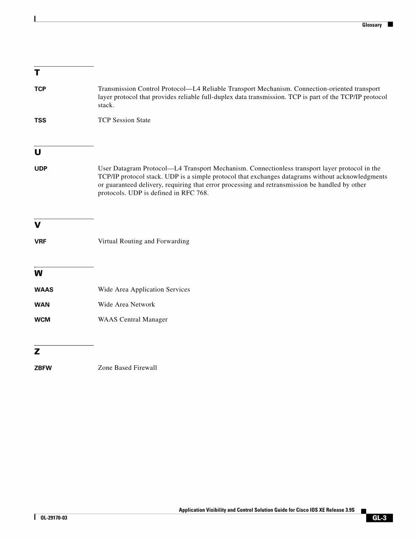
Glossary
T
TCP Transmission Control Protocol—L4 Reliable Transport Mechanism. Connection-oriented transport layer protocol that provides reliable full-duplex data transmission. TCP is part of the TCP/IP protocol stack.
TSS TCP Session State
U
UDP User Datagram Protocol—L4 Transport Mechanism. Connectionless transport layer protocol in the TCP/IP protocol stack. UDP is a simple protocol that exchanges datagrams without acknowledgments or guaranteed delivery, requiring that error processing and retransmission be handled by other protocols. UDP is defined in RFC 768.
V
VRF Virtual Routing and Forwarding
W
WAAS Wide Area Application Services
WAN Wide Area Network
WCM WAAS Central Manager
Z
ZBFW Zone Based Firewall
GL-3Application Visibility and Control Solution Guide for Cisco IOS XE Release 3.9S
OL-29170-03

Glossary
GL-4Application Visibility and Control Solution Guide for Cisco IOS XE Release 3.9S
OL-29170-03