Cisco Application Netw orking for BEA WebLogic Portal ... · GroupSpace is a WebLogic Portal...
62
Americas Headquarters: © 2007 Cisco Systems, Inc. All rights reserved. Cisco Systems, Inc., 170 West Tasman Drive, San Jose, CA 95134-1706 USA Cisco Application Networking for BEA WebLogic Portal Deployment Guide Cisco Validated Design February 18, 2009 Preface Document Purpose To address challenges associated with today’s mission critical enterprise application deployments, Cisco offers an enterprise network architecture for the ANS WebLogic solution with best practices and implementation guidance that optimizes application availability, performance, and security and lowers application ownership costs. Featuring the Cisco Application Control Engine (ACE) and Cisco Wide Area Application Services (WAAS) product families, collectively known as Cisco Application Networking Services (ANS), that provide data center, branch, and remote end user application optimization services, the solution addresses the following challenges for ANS WebLogic deployments: • Recovery time and point objectives for business continuity • End user performance over limited Wide Area Network (WAN) connections • Security for service-oriented application architectures (SOA) • Reduced capital and operational costs The purpose of this document is to describe the ANS WebLogic Solution enterprise network architecture and deployment best practices and guidance. Prerequisites The following prerequisites are required to deploy the BEA WebLogic Solution: • Working knowledge of the WebLogic application
Transcript of Cisco Application Netw orking for BEA WebLogic Portal ... · GroupSpace is a WebLogic Portal...
Cisco Application Networking for BEA WebLogic Portal Deployment Guide
Cisco Validated Design
February 18, 2009
Preface
Document PurposeTo address challenges associated with today’s mission critical enterprise application deployments, Cisco offers an enterprise network architecture for the ANS WebLogic solution with best practices and implementation guidance that optimizes application availability, performance, and security and lowers application ownership costs.
Featuring the Cisco Application Control Engine (ACE) and Cisco Wide Area Application Services (WAAS) product families, collectively known as Cisco Application Networking Services (ANS), that provide data center, branch, and remote end user application optimization services, the solution addresses the following challenges for ANS WebLogic deployments:
• Recovery time and point objectives for business continuity
• End user performance over limited Wide Area Network (WAN) connections
• Security for service-oriented application architectures (SOA)
• Reduced capital and operational costs
The purpose of this document is to describe the ANS WebLogic Solution enterprise network architecture and deployment best practices and guidance.
PrerequisitesThe following prerequisites are required to deploy the BEA WebLogic Solution:
• Working knowledge of the WebLogic application
Americas Headquarters:
© 2007 Cisco Systems, Inc. All rights reserved.
Cisco Systems, Inc., 170 West Tasman Drive, San Jose, CA 95134-1706 USA
Solution Overview
• Experience with basic networking and troubleshooting
• Experience installing the Cisco products covered by this network design, including the Cisco ACE and WAAS product families
• Working knowledge of Cisco’s Internetworking Operating System (IOS)
Document Organization
Solution Overview
Solution Description
•
– Application health monitoring—Continuously and intelligently monitors application and database availability.
– Server load balancing—Efficiently routes end user and Web services requests to the best available server.
– Network platform health monitoring—Ensures continuity of business operations through mirroring end user transaction states across pairs of network devices.
Application performance
Cisco ACE and WAAS product family application optimization services for WebLogic high performance:
– WAN optimization—Provides intelligent caching, compression, and protocol optimization.
Section Description
Network Management Describes the network management software used in the ANS WebLogic Solution.
2 OL-15557-01
–
Layer termination, and traffic compression, which frees up to 50 percent of application server processing and memory to focus on business logic computations.
Server load balancing—Substitutes for WebLogic load balancing.
Secure Socket Layer (SSL) termination—Terminates 15,000 connections per second.
Transmission Control Protocol (TCP) connection management—Reduces the number
Traffic compression—Scalable LZ compression functionality.
Object caching—Reduce requests to server.
Application security
Cisco ACE product family application optimization services for optimized WebLogic data security:
SSL termination—Efficiently encrypts and decrypts SSL enabled traffic, which facilitates the use of intrusion detection and prevention solutions before traffic reaches the servers.
End user access control—Provides Access Control Lists (ACLs) to protect client-to-server traffic from worms and intruders that attack vulnerable open server ports not used by the application.
Virtualization of application optimization services
Virtualization of application optimization services supplies such services for multiple WebLogic instances as well as other enterprise applications (see Figure 1). Specifically, a single physical Cisco ACE can be virtualized into multiple logical Cisco ACEs in which application traffic can traverse between virtualized Cisco ACEs. This virtualization of load balancing is an exclusive Cisco feature.
3
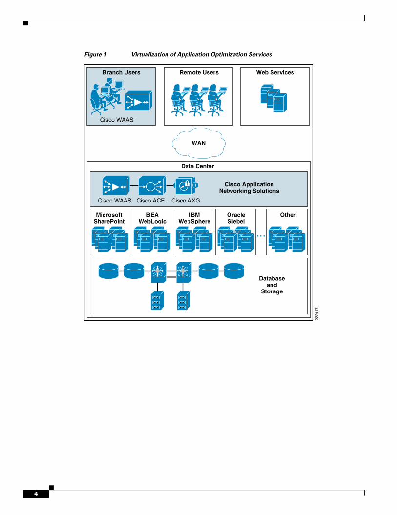
Figure 1 Virtualization of Application Optimization Services
Branch Users
MicrosoftSharePoint
Cisco WAAS
Cisco WAAS Cisco ACE Cisco AXG
WAN
Cisco ApplicationNetworking Solutions
Databaseand
Storage
OtherBEAWebLogic
IBMWebSphere
OracleSiebel
Remote Users
Data Center
Web Services
2229
17
4
configuration tools for business experts. GroupSpace is a WebLogic Portal application built entirely on Portal’s new community framework. GroupSpace provides an environment for collaboration of like-minded individuals, who come together in a “community” to share information. Because it is built on Portal, GroupSpace is an enterprise-level application, leveraging Portal’s security and content management system.
Note
5
Solution Overview
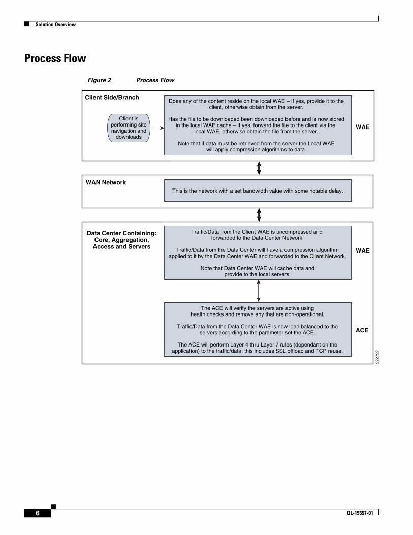
Process Flow
Figure 2 Process Flow
Client isperforming sitenavigation and
downloads
Does any of the content reside on the local WAE – If yes, provide it to theclient, otherwise obtain from the server.
Has the file to be downloaded been downloaded before and is now storedin the local WAE cache – If yes, forward the file to the client via the
local WAE, otherwise obtain the file from the server.
Note that if data must be retrieved from the server the Local WAEwill apply compression algorithms to data.
This is the network with a set bandwidth value with some notable delay.
Traffic/Data from the Client WAE is uncompressed and forwarded to the Data Center Network.
Traffic/Data from the Data Center will have a compression algorithmapplied to it by the Data Center WAE and forwarded to the Client Network.
Note that Data Center WAE will cache data andprovide to the local servers.
The ACE will verify the servers are active usinghealth checks and remove any that are non-operational.
Traffic/Data from the Data Center WAE is now load balanced to theservers according to the parameter set the ACE.
The ACE will perform Layer 4 thru Layer 7 rules (dependant on theapplication) to the traffic/data, this includes SSL offload and TCP reuse.
Data Center Containing:Core, Aggregation,Access and Servers
WAN Network
Client Side/Branch
WAE
WAE
ACE
2227
92
6 OL-15557-01
Solution Architecture
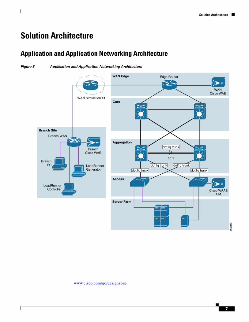
Solution Architecture
Application and Application Networking Architecture
Figure 3 Application and Application Networking Architecture
www.cisco.com/go/designzone.
Server Farm
WAN Simulation #1
BranchPC
Access
Aggregation
WAN Edge
Core
Branch Site
2228
10
Edge Router
Branch WAN
WANCisco WAE
LoadRunnerGenerator
LoadRunnerController
BranchCisco WAE
Cisco WAASCM
dot1q trunk
po 1
dot1q trunk
dot1q trunk dot1q trunk
dot1q trunk
7
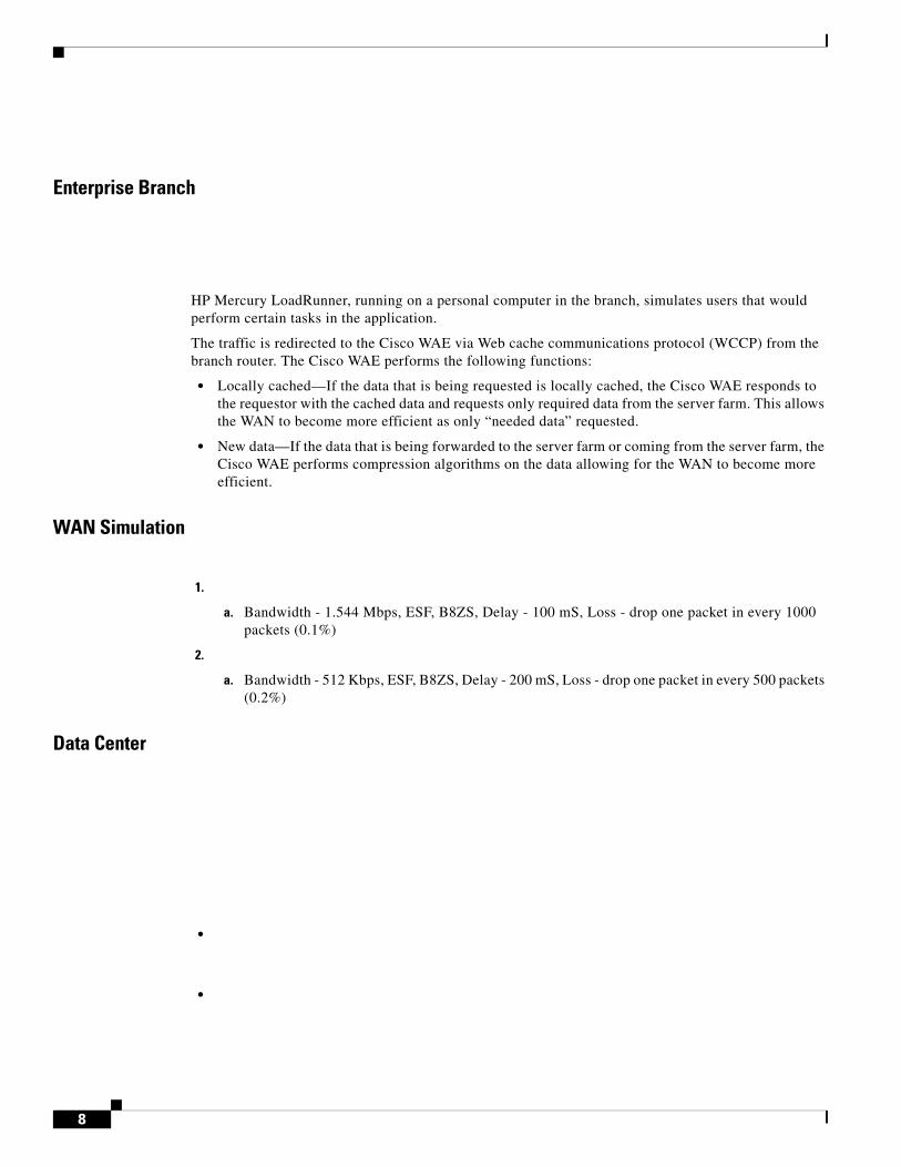
Enterprise Branch
HP Mercury LoadRunner, running on a personal computer in the branch, simulates users that would perform certain tasks in the application.
The traffic is redirected to the Cisco WAE via Web cache communications protocol (WCCP) from the branch router. The Cisco WAE performs the following functions:
• Locally cached—If the data that is being requested is locally cached, the Cisco WAE responds to the requestor with the cached data and requests only required data from the server farm. This allows the WAN to become more efficient as only “needed data” requested.
• New data—If the data that is being forwarded to the server farm or coming from the server farm, the Cisco WAE performs compression algorithms on the data allowing for the WAN to become more efficient.
WAN Simulation
1.
a. Bandwidth - 1.544 Mbps, ESF, B8ZS, Delay - 100 mS, Loss - drop one packet in every 1000 packets (0.1%)
2.
a. Bandwidth - 512 Kbps, ESF, B8ZS, Delay - 200 mS, Loss - drop one packet in every 500 packets (0.2%)
Data Center
•
•
8
Solution Architecture
•be configured for different applications and is independent of any others. In the Joint Solution, Cisco ACE is configured with the Admin context and the SharePoint context. Note that the Cisco ACE can support up to 250 contexts.
Session persistence—Session persistence is the ability to forward client requests to the same server for the duration of the session. MOSS requires either source Internet Protocol (IP) based session persistence or Hypertext Transfer Protocol (HTTP) cookie based session persistence.
Transparent interception—Transparent interception performs a Network Address Translation (NAT) function to conceal the real server IP address that is residing in the server farm. The SharePoint context is configured with a Virtual IP (VIP) that provides a single address that users use to connect to the server farm. This allows users to access the MOSS application by placing a single IP in the Web browser.
Allowed server connections—Allowed server connections is the maximum number of active connections value on a per-server basis and/or globally to the server farm.
Health monitoring—Health monitoring is used to track the state of the server and determine its ability to process connections in the server farm. The SharePoint context used a compound probe to determine if servers are operational and responding to HTTP requests.
Cisco ACE provides load balancing of the traffic to the server farm using one of the following methods: Round Robin, Weighted Round Robin, Least Connections, Hash address, Hash cookie, Hash Header, and Hash URL. In the Joint Solution, Least Connections was used, which selects the server with the fewest number of server connections. Cisco ACE is also used to provide SSL offload and TCP reuse.
Inter-chassis Cisco ACE redundancy was used, in which a Cisco ACE module in one Cisco Catalyst 6500 Series Switch chassis is protected by a Cisco ACE module in a peer Cisco Catalyst 6500 Series Switch chassis connected by a fault tolerant (FT) VLAN. The FT VLAN is used to transmit flow-state information, configuration synchronization information, and the redundancy heartbeat.
Server Farm
WebLogic Portal resides on the Windows 2003 enterprise server operating system. Dual Xeon processors running at 2.33 Ghz with 4 G of RAM and 4 80 G SATA hard drives were used.
9OL-15557-01
The IBM DB2 database version is 8.1.7. The IBM DB2 resides on the Windows 2003 enterprise server operating system. Dual Xeon processors running at 2.33 Ghz with 4 G of RAM and 4 80 G SATA hard drives were used. The gigabit network interface cards are “nic-teamed” for redundancy.
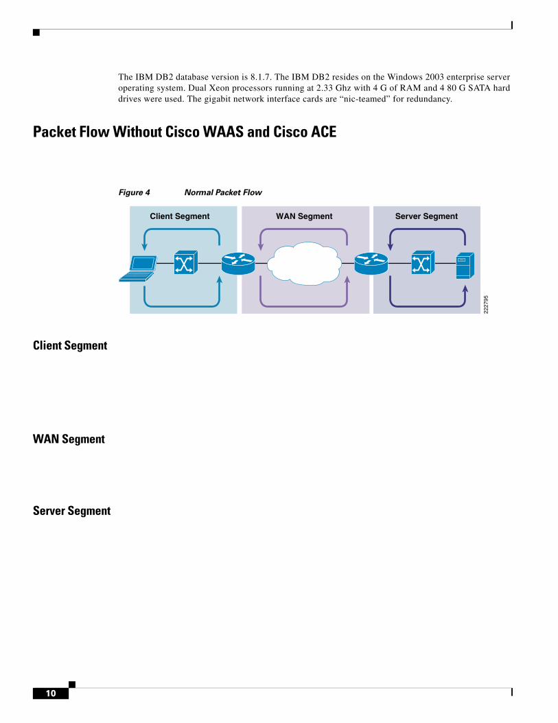
Packet Flow Without Cisco WAAS and Cisco ACE
Figure 4 Normal Packet Flow
Client Segment
WAN Segment
Server Segment
WAN Segment Server SegmentClient Segment
2227
95
10
Solution Architecture
Response Times
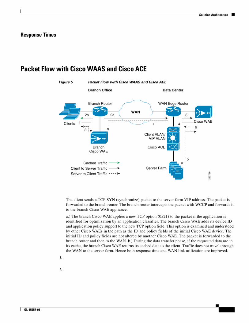
Packet Flow with Cisco WAAS and Cisco ACE
Figure 5 Packet Flow with Cisco WAAS and Cisco ACE
The client sends a TCP SYN (synchronize) packet to the server farm VIP address. The packet is forwarded to the branch router. The branch router intercepts the packet with WCCP and forwards it to the branch Cisco WAE appliance.
a.) The branch Cisco WAE applies a new TCP option (0x21) to the packet if the application is identified for optimization by an application classifier. The branch Cisco WAE adds its device ID and application policy support to the new TCP option field. This option is examined and understood by other Cisco WAEs in the path as the ID and policy fields of the initial Cisco WAE device. The initial ID and policy fields are not altered by another Cisco WAE. The packet is forwarded to the branch router and then to the WAN. b.) During the data transfer phase, if the requested data are in its cache, the branch Cisco WAE returns its cached data to the client. Traffic does not travel through the WAN to the server farm. Hence both response time and WAN link utilization are improved.
3.
4.
Data CenterBranch Office
2b
1
8
2a
7 4
3
Cisco WAE
Branch Router
Server Farm
Client VLAN/VIP VLAN
Cisco ACE
Cached Traffic
WAN Edge Router
2227
96
WAN
BranchCisco WAE
Client to Server Traffic
Server to Client Traffic
6
5
Clients
OL-15557-01
Implementing and Configuring the Cisco ACE Solution
5.
6.
7.
8.
Implementing and Configuring the Cisco ACE Solution
Implementation
Implementation Overview
What Was Implemented
•
•
•
•
•
What Was Not Implemented/Tested
•
OL-15557-01
Implementing and Configuring the Cisco ACE Solution
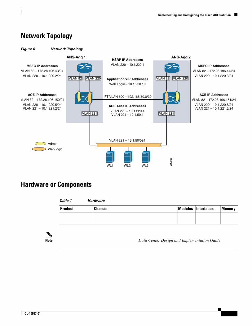
Network Topology
Figure 6 Network Topology
Hardware or Components
Note Data Center Design and Implementation Guide
Table 1 Hardware
Product Chassis Modules Interfaces Memory
HSRP IP Addresses
VLAN 220 – 10.1.220.1
ACE Alias IP Addresses
VLAN 220 – 10.1.220.4VLAN 221 – 10.1.50.1
ACE IP Addresses
VLAN 82 – 172.28.196.150/24
VLAN 220 – 10.1.220.5/24VLAN 221 – 10.1.221.2/24
MSFC IP Addresses
VLAN 82 – 172.28.196.43/24
VLAN 220 – 10.1.220.2/24
ACE IP Addresses
VLAN 82 – 172.28.196.151/24
VLAN 220 – 10.1.220.6/24VLAN 221 – 10.1.221.3/24
MSFC IP Addresses
VLAN 82 – 172.28.196.44/24
VLAN 220 – 10.1.220.3/24Application VIP Addresses
Web Logic – 10.1.220.10
FT VLAN 500 – 192.168.50.0/30
WL1 WL2 WL3
VLAN 221 – 13.1.50/024Admin
WebLogic
VLAN 82VLAN 82
2228
06
ANS-Agg 1 ANS-Agg 2
VLAN 220
VLAN 221
VLAN 220
VLAN 221
OL-15557-01
Implementing and Configuring the Cisco ACE Solution
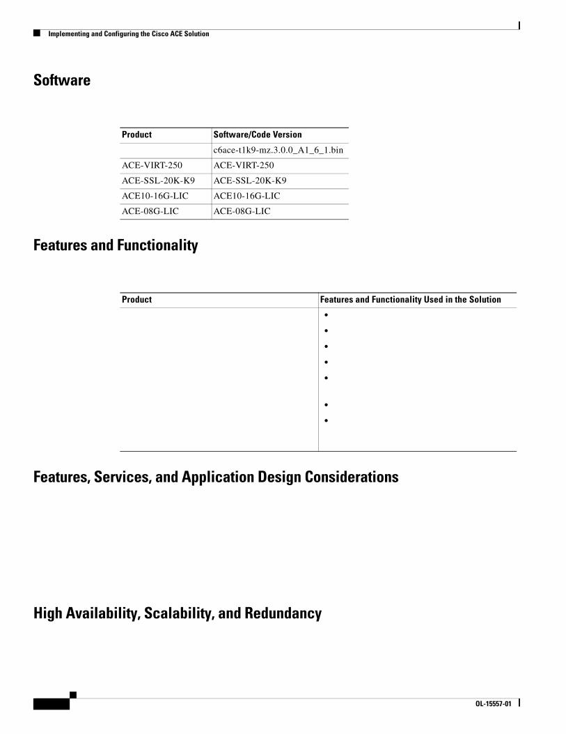
Software
Features and Functionality
Features, Services, and Application Design Considerations
High Availability, Scalability, and Redundancy
Product Software/Code Version
c6ace-t1k9-mz.3.0.0_A1_6_1.bin
ACE-VIRT-250 ACE-VIRT-250
ACE-SSL-20K-K9 ACE-SSL-20K-K9
ACE10-16G-LIC ACE10-16G-LIC
ACE-08G-LIC ACE-08G-LIC
Product Features and Functionality Used in the Solution
•
•
•
•
•
•
•
OL-15557-01
Implementing and Configuring the Cisco ACE Solution
•
•
•
Configuration Task Lists
Installing Cisco ACE and MSFC Configuration
Step 1
vlan 220 name ACE-CLIENT!vlan 221 name ACE-SERVER!vlan 500 name ACE-FT-VLAN!
svclc multiple-vlan-interfacessvclc module 3 vlan-group 1svclc vlan-group 1 220,221,500
interface Vlan220 description ACE Client Side VLAN ip address 10.1.220.2 255.255.255.0
OL-15557-01
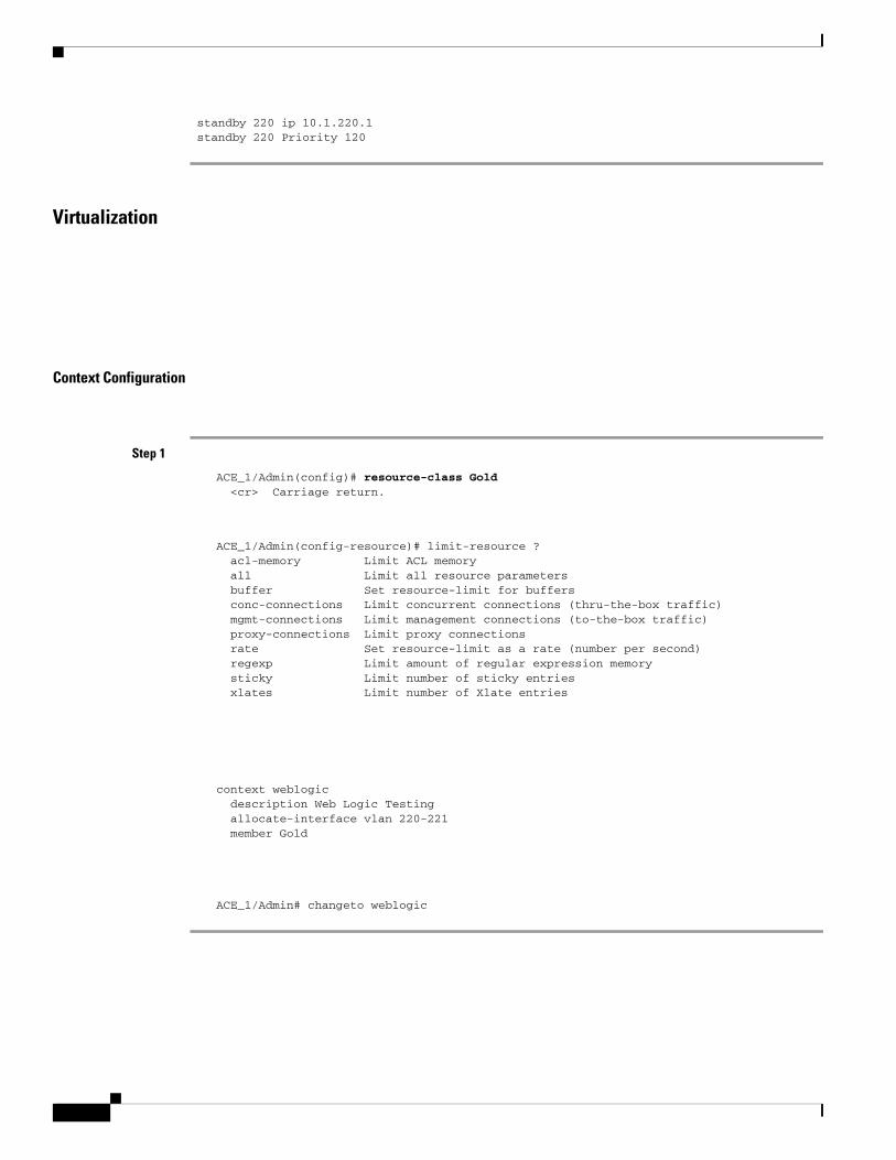
standby 220 ip 10.1.220.1 standby 220 Priority 120
Virtualization
Context Configuration
Step 1
ACE_1/Admin(config)# resource-class Gold <cr> Carriage return.
ACE_1/Admin(config-resource)# limit-resource ? acl-memory Limit ACL memory all Limit all resource parameters buffer Set resource-limit for buffers conc-connections Limit concurrent connections (thru-the-box traffic) mgmt-connections Limit management connections (to-the-box traffic) proxy-connections Limit proxy connections rate Set resource-limit as a rate (number per second) regexp Limit amount of regular expression memory sticky Limit number of sticky entries xlates Limit number of Xlate entries
context weblogic description Web Logic Testing allocate-interface vlan 220-221 member Gold
ACE_1/Admin# changeto weblogic
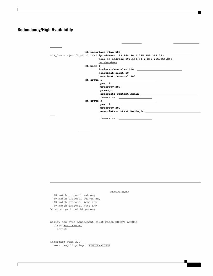
Redundancy/High Availability
ft interface vlan 500ACE_1/Admin(config-ft-intf)# ip address 192.168.50.1 255.255.255.252
peer ip address 192.168.50.2 255.255.255.252no shutdown
ft peer 1ft-interface vlan 500heartbeat count 10heartbeat interval 300
ft group 1peer 1priority 200preemptassociate-context Admininservice
ft group 3peer 1priority 200associate-context Weblogic
inservice
REMOTE-MGMT 10 match protocol ssh any 20 match protocol telnet any 30 match protocol icmp any 40 match protocol http any50 match protocol https any
policy-map type management first-match REMOTE-ACCESS class REMOTE-MGMT permit
interface vlan 220 service-policy input REMOTE-ACCESS
interface vlan 221service-policy input REMOTE-ACCESS
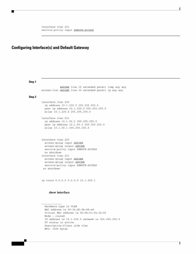
Configuring Interface(s) and Default Gateway
Step 1
ANYONE line 10 extended permit icmp any anyaccess-list ANYONE line 20 extended permit ip any any
Step 2
interface vlan 220 ip address 10.1.220.5 255.255.255.0 peer ip address 10.1.220.6 255.255.255.0 alias 10.1.220.4 255.255.255.0 interface vlan 221 ip address 10.1.50.2 255.255.255.0 peer ip address 10.1.50.3 255.255.255.0 alias 10.1.50.1 255.255.255.0
interface vlan 220 access-group input ANYONE access-group output ANYONE service-policy input REMOTE-ACCESS no shutdowninterface vlan 221 access-group input ANYONE access-group output ANYONE service-policy input REMOTE-ACCESS no shutdown
ip route 0.0.0.0 0.0.0.0 10.1.220.1
show interface
Hardware type is VLAN MAC address is 00:1b:d5:9b:88:ed Virtual MAC address is 00:0b:fc:fe:1b:02 Mode : routed IP address is 10.1.220.5 netmask is 255.255.255.0 FT status is active Description:Client side vlan MTU: 1500 bytes
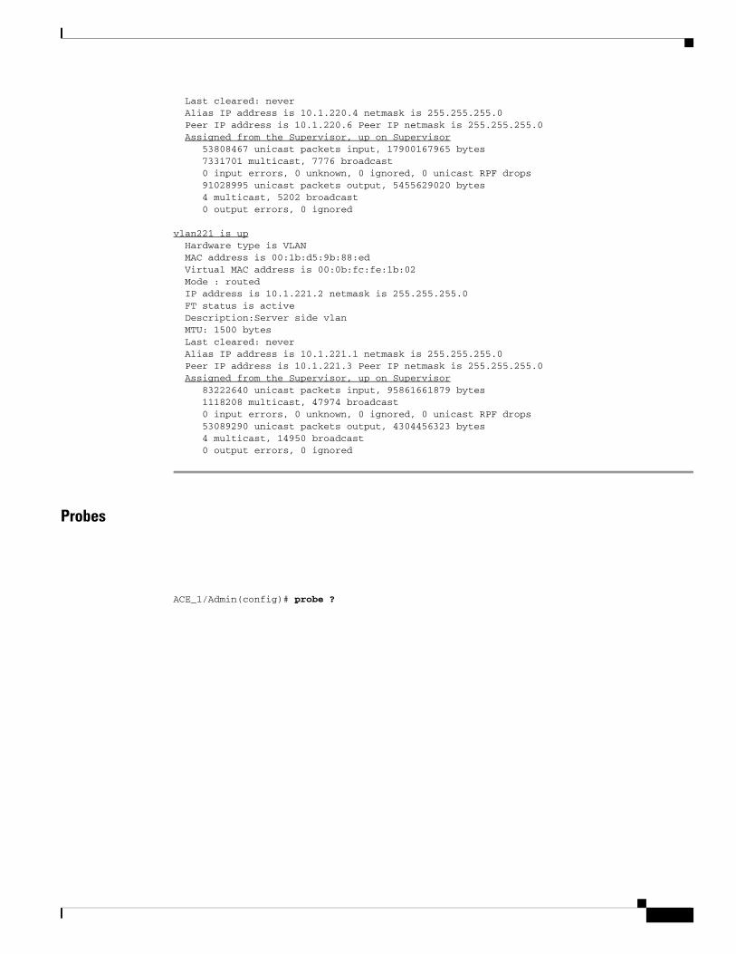
Last cleared: never Alias IP address is 10.1.220.4 netmask is 255.255.255.0 Peer IP address is 10.1.220.6 Peer IP netmask is 255.255.255.0 Assigned from the Supervisor, up on Supervisor 53808467 unicast packets input, 17900167965 bytes 7331701 multicast, 7776 broadcast 0 input errors, 0 unknown, 0 ignored, 0 unicast RPF drops 91028995 unicast packets output, 5455629020 bytes 4 multicast, 5202 broadcast 0 output errors, 0 ignored
vlan221 is up Hardware type is VLAN MAC address is 00:1b:d5:9b:88:ed Virtual MAC address is 00:0b:fc:fe:1b:02 Mode : routed IP address is 10.1.221.2 netmask is 255.255.255.0 FT status is active Description:Server side vlan MTU: 1500 bytes Last cleared: never Alias IP address is 10.1.221.1 netmask is 255.255.255.0 Peer IP address is 10.1.221.3 Peer IP netmask is 255.255.255.0 Assigned from the Supervisor, up on Supervisor 83222640 unicast packets input, 95861661879 bytes 1118208 multicast, 47974 broadcast 0 input errors, 0 unknown, 0 ignored, 0 unicast RPF drops 53089290 unicast packets output, 4304456323 bytes 4 multicast, 14950 broadcast 0 output errors, 0 ignored
Probes
ACE_1/Admin(config)# probe ?

HTTP return code expected; it has to be explicitly configured.
expect regex—A regex can be configured to parse a specific field in the response data.
This parameter is only applicable to HTTP/HTTPS probes.
SSL—Configured to define what cipher and SSL version Cisco ACE should use when sending an HTTPS probe. Ciphers and SSL versions supported on Cisco ACE are:
RSA_EXPORT1024_WITH_DES_CBC_SHA EXP1024-DES-CBC-SHA Cipher RSA_EXPORT1024_WITH_RC4_56_MD5 EXP1024-RC4-MD5 Cipher

RSA_EXPORT1024_WITH_RC4_56_SHA EXP1024-RC4-SHA Cipher RSA_EXPORT_WITH_DES40_CBC_SHA EXP-DES-CBC-SHA Cipher RSA_EXPORT_WITH_RC4_40_MD5 EXP-RC4-MD5 Cipher RSA_WITH_3DES_EDE_CBC_SHA 3DES-EDE-CBC-SHA Cipher RSA_WITH_AES_128_CBC_SHA AES-128-CBC-SHA Cipher RSA_WITH_AES_256_CBC_SHA AES-256-CBC-SHA Cipher RSA_WITH_DES_CBC_SHA DES-CBC-SHA Cipher RSA_WITH_RC4_128_MD5 RC4-MD5 Cipher RSA_WITH_RC4_128_SHA RC4-SHA Cipher
ssl versions: SSLv2 SSL Version 2.0 SSLv3 SSL Version 3.0 TLSv1 TLS Version 1.0
probe tcp PROBE-TCP interval 2 faildetect 2 passdetect interval 10passdetect count 2
probe icmp PING interval 2 faildetect 2
rserver host WL1 ip address 10.1.50.51 inservice
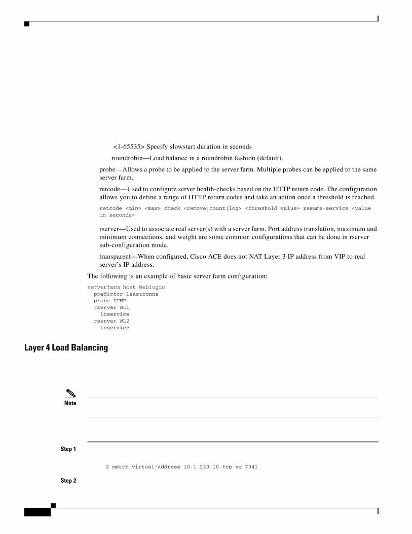
<1-65535> Specify slowstart duration in seconds
roundrobin—Load balance in a roundrobin fashion (default).
probe—Allows a probe to be applied to the server farm. Multiple probes can be applied to the same server farm.
retcode—Used to configure server health-checks based on the HTTP return code. The configuration allows you to define a range of HTTP return codes and take an action once a threshold is reached.
retcode <min> <max> check <remove|count|log> <threshold value> resume-service <value in seconds>
rserver—Used to associate real server(s) with a server farm. Port address translation, maximum and minimum connections, and weight are some common configurations that can be done in rserver sub-configuration mode.
transparent—When configured, Cisco ACE does not NAT Layer 3 IP address from VIP to real server’s IP address.
The following is an example of basic server farm configuration:
serverfarm host Weblogic predictor leastconns probe ICMP rserver WL1 inservice rserver WL2 inservice
Layer 4 Load Balancing
Note
Step 1
2 match virtual-address 10.1.220.10 tcp eq 7041
Step 2
Implementing and Configuring the Cisco ACE Solution
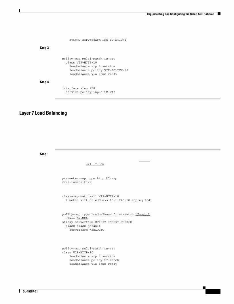
sticky-serverfarm SRC-IP-STICKY
Step 3
policy-map multi-match LB-VIP class VIP-HTTP-10 loadbalance vip inservice loadbalance policy VIP-POLICY-10 loadbalance vip icmp-reply
Step 4
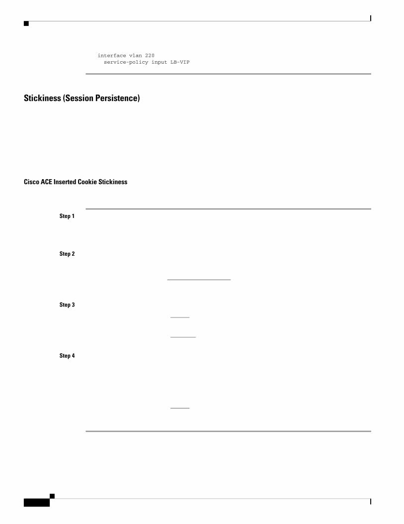
interface vlan 220 service-policy input LB-VIP
Layer 7 Load Balancing
Step 1
url .*.htm
parameter-map type http L7-mapcase-insensitive
class-map match-all VIP-HTTP-10 2 match virtual-address 10.1.220.10 tcp eq 7041
policy-map type loadbalance first-match L7-match class L7-URLsticky-serverfarm STICKY-INSERT-COOKIE class class-default serverfarm WEBLOGIC
policy-map multi-match LB-VIPclass VIP-HTTP-10 loadbalance vip inservice loadbalance policy L7-match loadbalance vip icmp-reply
OL-15557-01
interface vlan 220 service-policy input LB-VIP
Stickiness (Session Persistence)
Cisco ACE Inserted Cookie Stickiness
Step 1
Step 2
Step 3
Step 4
Implementing and Configuring the Cisco ACE Solution
SSL Termination
Front End SSL Termination
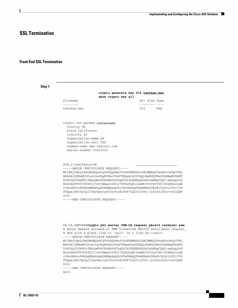
Step 1
crypto generate key 512 testkey.keyshow crypto key all
Filename Bit Size Type-------- -------- ----testkey.key 512 RSA
crypto csr-params testparams country US state California locality SJ organization-name AS organization-unit TAS common-name www.testssl.com serial-number cisco123
ACE_1/testfeature# -----BEGIN CERTIFICATE REQUEST-----MIIBHjCByQIBADBkMQswCQYDVQQGEwJVUzETMBEGA1UECBMKQ2FsaWZvcm5pYTELMAkGA1UEBxMCU0oxCzAJBgNVBAoTAkFTMQwwCgYDVQQLEwNUQVMxGDAWBgNVBAMTD3d3dy50ZXN0c3NsLmNvbTBcMA0GCSqGSIb3DQEBAQUAA0sAMEgCQQC+xphqQJn9EOzOhkFfVCVO5SYJj7nVjWmaslVZOi7TYKzFgXtJexMt0Y1VyO7XY+U5XdZuvoxEcO4rdAGzo84HAgMBAAGgADANBgkqhkiG9w0BAQQFAANBAAL9EzKcYyOrL3XYc7YGSTgpa1B8tTpCpJIVwrHwolyK3OzvfudLTbF7CQ2V3jUYS//sf2Cei8fe+voKIQE9nI4=-----END CERTIFICATE REQUEST-----
OS-CA-SERVER#crypto pki server CDN-CA request pkcs10 terminal pem% Enter Base64 encoded or PEM formatted PKCS10 enrollment request.% End with a blank line or "quit" on a line by itself.-----BEGIN CERTIFICATE REQUEST-----MIIBHjCByQIBADBkMQswCQYDVQQGEwJVUzETMBEGA1UECBMKQ2FsaWZvcm5pYTELMAkGA1UEBxMCU0oxCzAJBgNVBAoTAkFTMQwwCgYDVQQLEwNUQVMxGDAWBgNVBAMTD3d3dy50ZXN0c3NsLmNvbTBcMA0GCSqGSIb3DQEBAQUAA0sAMEgCQQC+xphqQJn9EOzOhkFfVCVO5SYJj7nVjWmaslVZOi7TYKzFgXtJexMt0Y1VyO7XY+U5XdZuvoxEcO4rdAGzo84HAgMBAAGgADANBgkqhkiG9w0BAQQFAANBAAL9EzKcYyOrL3XYc7YGSTgpa1B8tTpCpJIVwrHwolyK3OzvfudLTbF7CQ2V3jUYS//sf2Cei8fe+voKIQE9nI4=-----END CERTIFICATE REQUEST-----Quit
OL-15557-01

% Granted certificate:-----BEGIN CERTIFICATE-----MIIB6TCCAVKgAwIBAgIBCTANBgkqhkiG9w0BAQQFADARMQ8wDQYDVQQDEwZDRE4tQ0EwHhcNMDYwNDI2MTgxNjQzWhcNMDcwNDI2MTgxNjQzWjBkMQswCQYDVQQGEwJVUzETMBEGA1UECBMKQ2FsaWZvcm5pYTELMAkGA1UEBxMCU0oxCzAJBgNVBAoTAkFTMQwwCgYDVQQLEwNUQVMxGDAWBgNVBAMTD3d3dy50ZXN0c3NsLmNvbTBcMA0GCSqGSIb3DQEBAQUAA0sAMEgCQQC+xphqQJn9EOzOhkFfVCVO5SYJj7nVjWmaslVZOi7TYKzFgXtJexMt0Y1VyO7XY+U5XdZuvoxEcO4rdAGzo84HAgMBAAGjQjBAMB8GA1UdIwQYMBaAFNKc5JGHmabT17tofs9CUD8mxVURMB0GA1UdDgQWBBQAL2ptyfN85SoVNdEiGRav8nI8lTANBgkqhkiG9w0BAQQFAAOBgQAUHyfbs+aMapSEFXmdlKPh8F67gGuYBdyWxmXjR7KVErDxde+4UqJCkNP4R2m11g30j6UveG2wLiP7C4IZHzGfFXUbzdPhaZ1838qgZlFn+lXPtCrayto1PitWeuPbCwLTxmE2vWWLw6lwEzguVbF+6t0nmLAkyiYsuz/MOiql/g==-----END CERTIFICATE-----
IOS-CA-SERVER#
ACE_1/testfeature# Please enter PEM formatted data. End with "quit" on a new line. -----BEGIN CERTIFICATE----- MIIB6TCCAVKgAwIBAgIBCTANBgkqhkiG9w0BAQQFADARMQ8wDQYDVQQDEwZDRE4t Q0EwHhcNMDYwNDI2MTgxNjQzWhcNMDcwNDI2MTgxNjQzWjBkMQswCQYDVQQGEwJV UzETMBEGA1UECBMKQ2FsaWZvcm5pYTELMAkGA1UEBxMCU0oxCzAJBgNVBAoTAkFT MQwwCgYDVQQLEwNUQVMxGDAWBgNVBAMTD3d3dy50ZXN0c3NsLmNvbTBcMA0GCSqG SIb3DQEBAQUAA0sAMEgCQQC+xphqQJn9EOzOhkFfVCVO5SYJj7nVjWmaslVZOi7T YKzFgXtJexMt0Y1VyO7XY+U5XdZuvoxEcO4rdAGzo84HAgMBAAGjQjBAMB8GA1Ud IwQYMBaAFNKc5JGHmabT17tofs9CUD8mxVURMB0GA1UdDgQWBBQAL2ptyfN85SoV NdEiGRav8nI8lTANBgkqhkiG9w0BAQQFAAOBgQAUHyfbs+aMapSEFXmdlKPh8F67 gGuYBdyWxmXjR7KVErDxde+4UqJCkNP4R2m11g30j6UveG2wLiP7C4IZHzGfFXUb zdPhaZ1838qgZlFn+lXPtCrayto1PitWeuPbCwLTxmE2vWWLw6lwEzguVbF+6t0n mLAkyiYsuz/MOiql/g== -----END CERTIFICATE----- quit
ACE_1/testfeature# Keypair in testkey.key matches certificate in testcert.pem.
parameter-map type ssl sslparams cipher RSA_WITH_RC4_128_MD5 version SSL3
b.
Step 8
Implementing and Configuring the Cisco ACE Solution
Step 9
Configuration and Menus
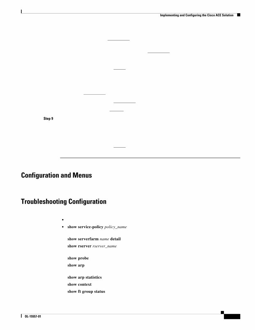
Troubleshooting Configuration
•
• show service-policy policy_name
show serverfarm name detail
show rserver rserver_name
show probe
show arp
show arp statistics
show context
show ft group status
OL-15557-01
Implementing and Configuring the Cisco WAAS Solution
• show ft peer detail
• show resource usage
• show np NP_number
name
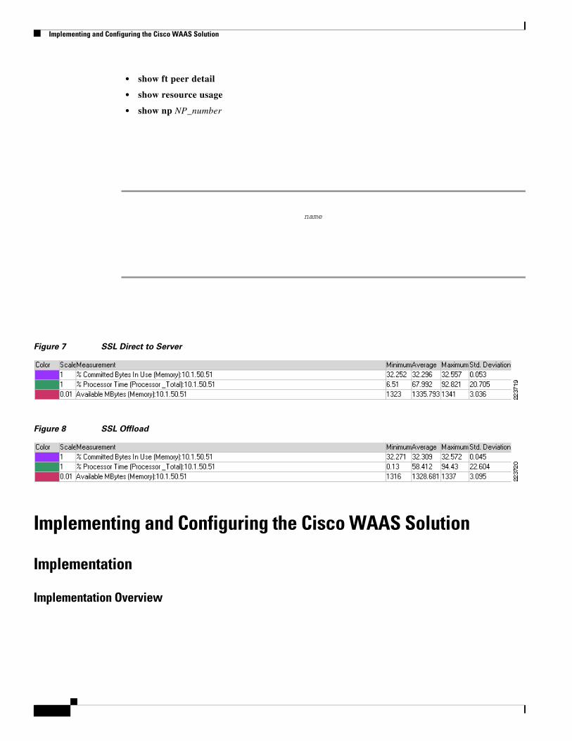
Figure 7 SSL Direct to Server
Figure 8 SSL Offload
Implementing and Configuring the Cisco WAAS Solution
Implementation
Implementation Overview
Implementing and Configuring the Cisco WAAS Solution
What Was Implemented
•
•
•
•
Note
What Was Not Implemented
•
OL-15557-01
Implementing and Configuring the Cisco WAAS Solution
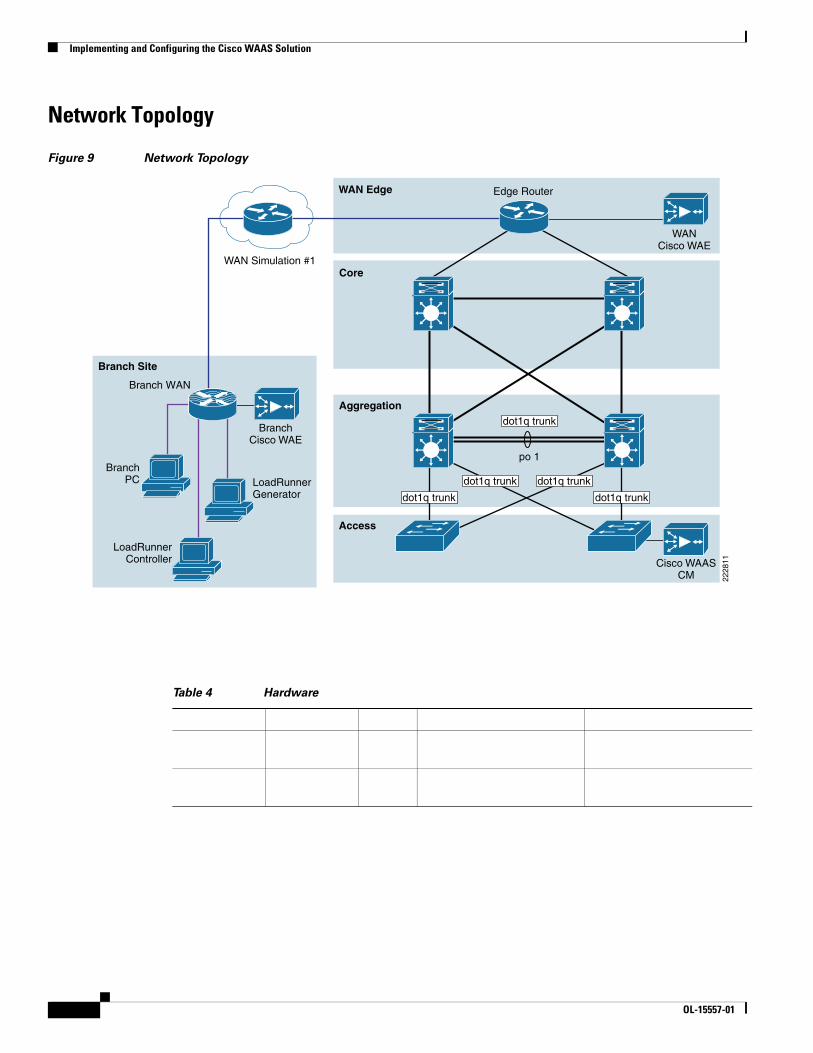
Network Topology
Figure 9 Network Topology
Table 4 Hardware
WAN Simulation #1
BranchPC
Access
Aggregation
WAN Edge
Core
Branch Site
2228
11
Edge Router
Branch WAN
WANCisco WAE
LoadRunnerGenerator
LoadRunnerController
BranchCisco WAE
Cisco WAASCM
dot1q trunk
po 1
dot1q trunk
dot1q trunk dot1q trunk
dot1q trunk
OL-15557-01

Enterprise Data Center Wide Area Application Services (WAAS) Design Guide
Enterprise Branch Wide Area Application Services Design Guide (Version 1.1)

balancing. Cisco WAAS services scale linearly in a N+1 configuration. In addition to the Max Optimized TCP connections, the fan out ratio between the DC Cisco WAE and branch Cisco WAE have to be considered. The fan out ratio is determined by a number of factors, such as the number of Cisco WAEs in the branch offices, amount of network traffic, and number of TCP connections. A sizing tool is available internally that can help automate sizing decisions. NetFlow, NetQoS, and other network analysis tools can provide additional traffic flow information for increased accuracy in scalability and capacity planning.
Branch devices range from the NME-WAE-302 for very small offices to the 612-4GB or even higher models for bigger branch sites. WAE 7326 and up are designed for data center installations.
Cisco WAAS deployments are transparent to the application. The application client and server do not know Cisco WAAS is optimizing traffic flows. High availability is built into the WCCP interception. When WCCP is not active or if Cisco WAAS devices are not functioning, WCCP does not forward traffic to the Cisco WAEs, resulting in un-optimized traffic flow. This is the worse case scenario; traffic flow continues but is not optimized.
Device
Max Optimized TCP Connections
Max CIFS Sessions
Single Drive Capacity [GB]
Max Drives RAM [GB]
Max Recommended WAN Link [Mbps]
Max Optimized Throughput [Mbps]
Max Core Fan-out [Peers]
CM Scalability [Devices]
Implementing and Configuring the Cisco WAAS Solution
Device High Availability
N+1 Availability
Configuration Task Lists
Central Manager
Note
Step 1
OL-15557-01
Implementing and Configuring the Cisco WAAS Solution
Step 2
Step 3
Step 4
Step 5
Step 6
Step 7
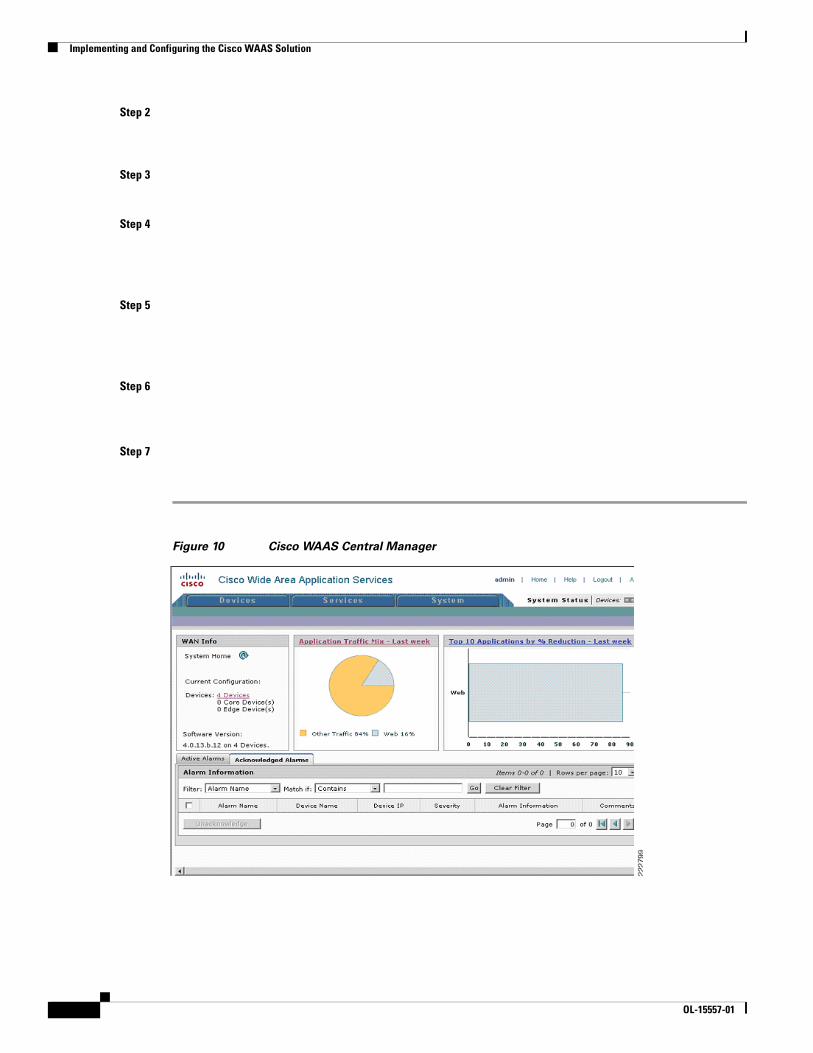
Figure 10 Cisco WAAS Central Manager
OL-15557-01


Step 10
Step 11
WAE-612-K9, WAE-7326-K9
Step 1
Step 2
Step 3
Step 4
Step 5
Step 6
Step 7
Implementing and Configuring the Cisco WAAS Solution
Step 8
Step 9
Step 10
Step 11
Configuration and Menus
Troubleshooting Configuration
Cisco WAE Commands
•
•
•
•
•
OL-15557-01
Implementing and Configuring the Cisco WAAS Solution
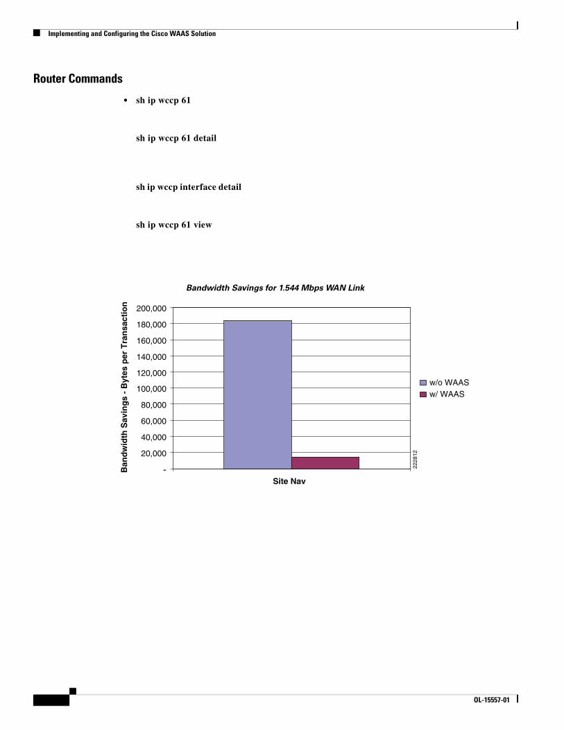
Router Commands
• sh ip wccp 61
sh ip wccp 61 detail
sh ip wccp interface detail
sh ip wccp 61 view
Bandwidth Savings for 1.544 Mbps WAN Link
2228
12
-
20,000
40,000
60,000
80,000
100,000
120,000
140,000
160,000
180,000
200,000
Site Nav
Ban
dw
idth
Sav
ing
s -
Byt
es p
er T
ran
sact
ion
w/o WAASw/ WAAS
OL-15557-01
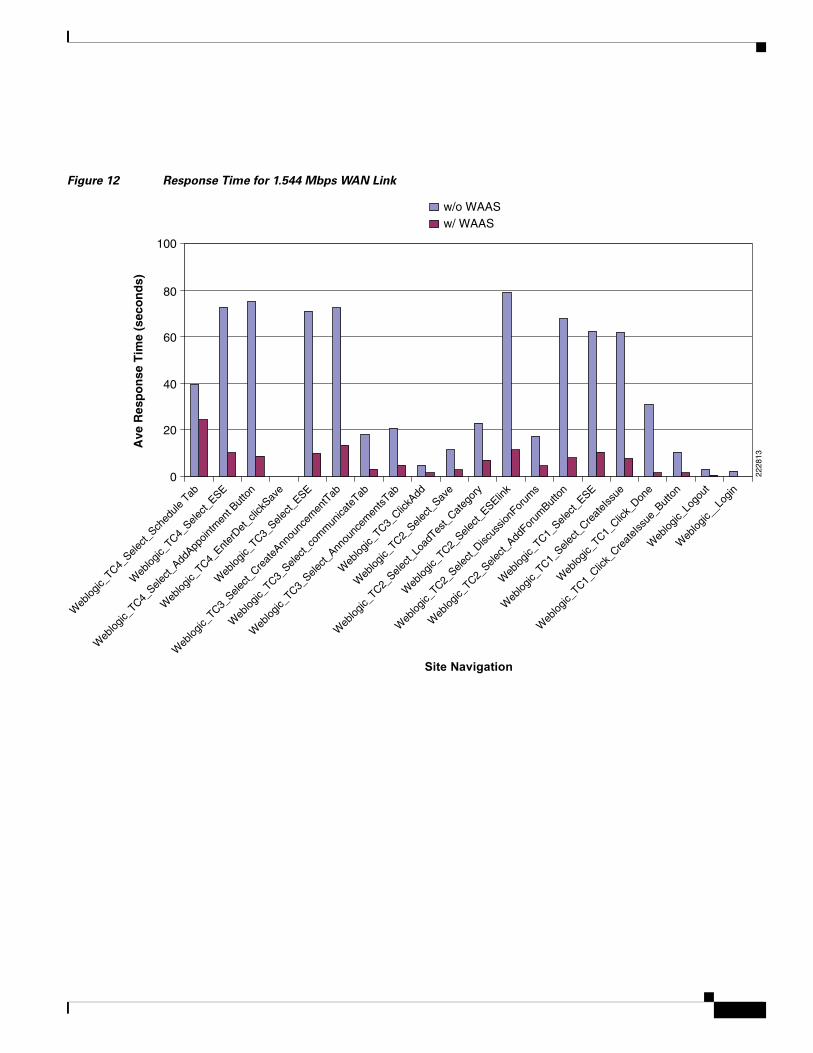
Figure 12 Response Time for 1.544 Mbps WAN Link
2228
13
0
20
40
60
80
100
Ave
Res
po
nse
Tim
e (s
eco
nd
s)
w/o WAASw/ WAAS
Site Navigation
Web
logic_
_Log
in
Web
logic_
Logo
ut
Web
logic_
TC1_Clic
k_Cre
ateI
ssue
_But
ton
Web
logic_
TC1_Sele
ct_Cre
ateI
ssue
Web
logic_
TC1_Clic
k_Don
e
Web
logic_
TC2_Sele
ct_Disc
ussio
nFor
ums
Web
logic_
TC2_Sele
ct_Add
Forum
Butto
n
Web
logic_
TC1_Sele
ct_ESE
Web
logic_
TC2_Sele
ct_Lo
adTes
t_Cat
egor
y
Web
logic_
TC2_Sele
ct_ESElin
k
Web
logic_
TC3_Sele
ct_Ann
ounc
emen
tsTab
Web
logic_
TC3_Clic
kAdd
Web
logic_
TC2_Sele
ct_Sav
e
Web
logic_
TC3_Sele
ct_co
mm
unica
teTab
Web
logic_
TC3_Sele
ct_Cre
ateA
nnou
ncem
entT
ab
Web
logic_
TC3_Sele
ct_ESE
Web
logic_
TC4_Ent
erDet
_clic
kSav
e
Web
logic_
TC4_Sele
ct_Add
Appoin
tmen
t But
ton
Web
logic_
TC4_Sele
ct_ESE
Web
logic_
TC4_Sele
ct_Sch
edule
Tab
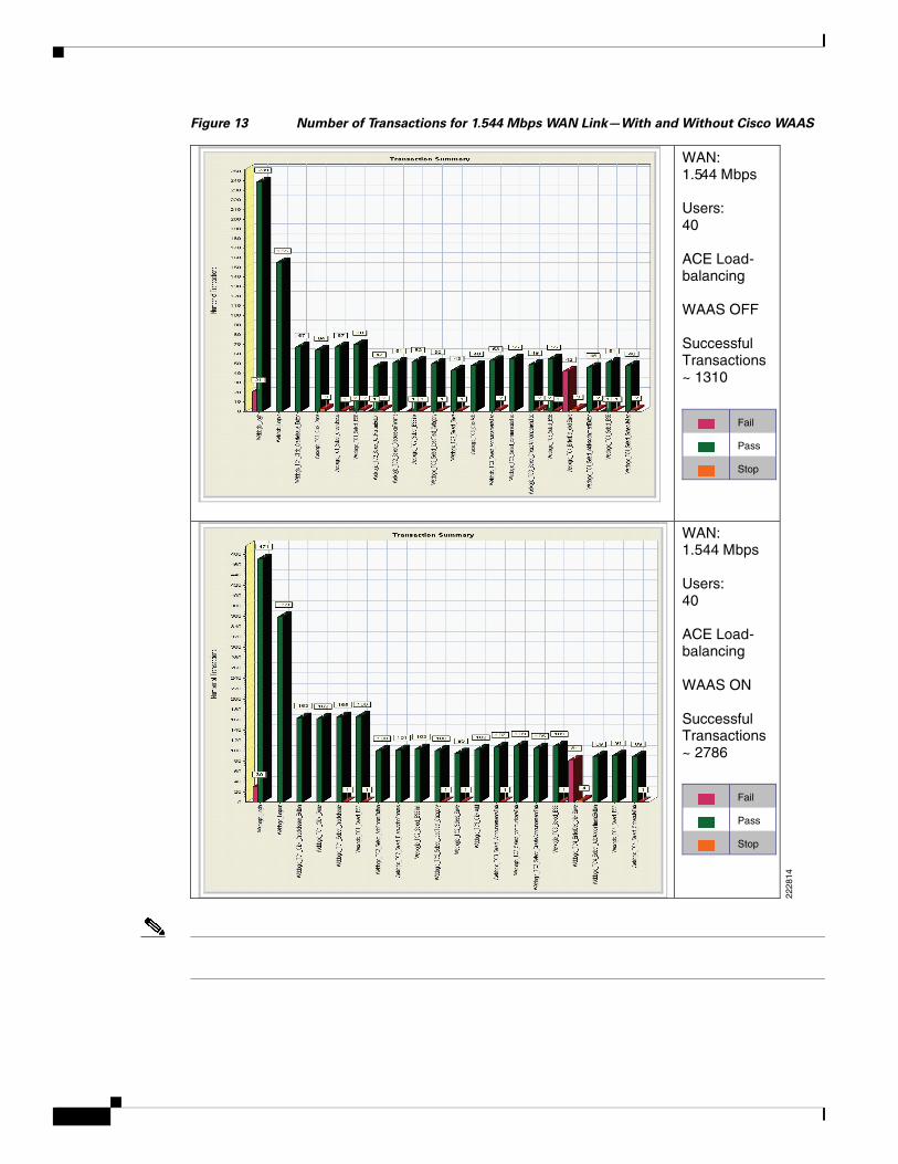
Figure 13 Number of Transactions for 1.544 Mbps WAN Link—With and Without Cisco WAAS
2228
14
WAN: 1.544 Mbps
Users:40
ACE Load-balancing
WAAS OFF
Successful Transactions~ 1310
Fail
Pass
Stop
Fail
Pass
Stop
WAN: 1.544 Mbps
Users:40
ACE Load-balancing
WAAS ON
Successful Transactions~ 2786
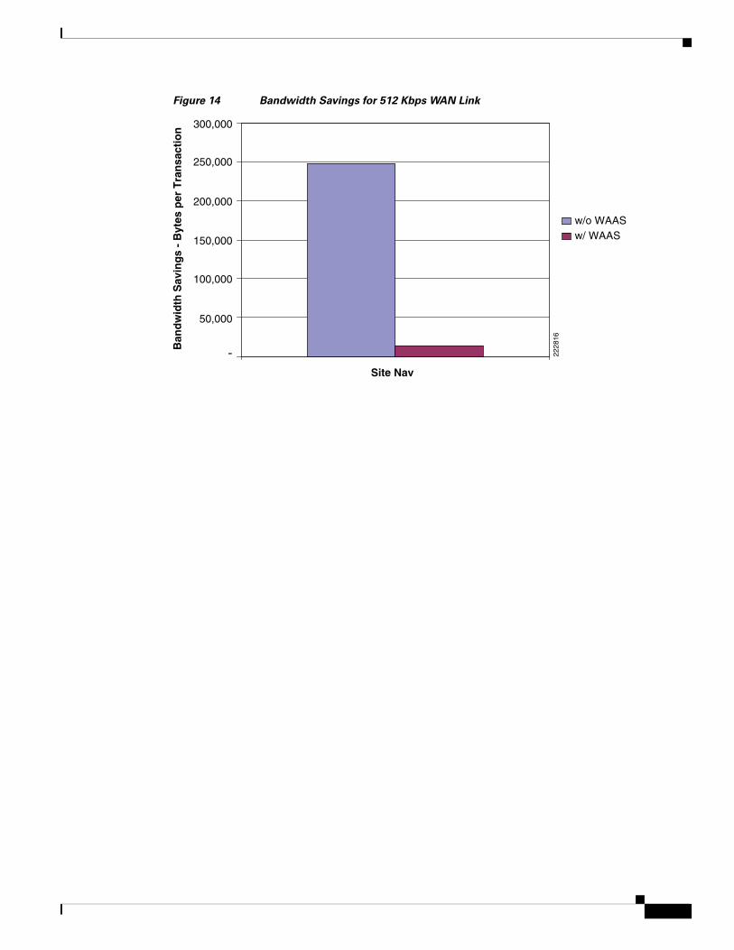
Figure 14 Bandwidth Savings for 512 Kbps WAN Link
2228
16
-
50,000
100,000
150,000
200,000
250,000
300,000
Site Nav
Ban
dw
idth
Sav
ing
s -
Byt
es p
er T
ran
sact
ion
w/o WAASw/ WAAS
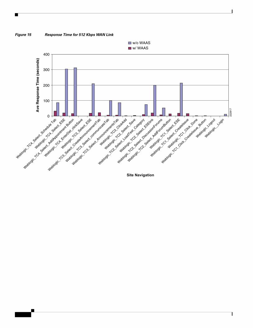
Figure 15 Response Time for 512 Kbps WAN Link
2228
17
0
100
200
300
400
Ave
Res
po
nse
Tim
e (s
eco
nd
s)w/o WAASw/ WAAS
Site Navigation
Web
logic_
_Log
in
Web
logic_
Logo
ut
Web
logic_
TC1_Clic
k_Cre
ateI
ssue
_But
ton
Web
logic_
TC1_Sele
ct_Cre
ateI
ssue
Web
logic_
TC1_Clic
k_Don
e
Web
logic_
TC2_Sele
ct_Disc
ussio
nFor
ums
Web
logic_
TC2_Sele
ct_Add
Forum
Butto
n
Web
logic_
TC1_Sele
ct_ESE
Web
logic_
TC2_Sele
ct_Lo
adTes
t_Cat
egor
y
Web
logic_
TC2_Sele
ct_ESElin
k
Web
logic_
TC3_Sele
ct_Ann
ounc
emen
tsTab
Web
logic_
TC3_Clic
kAdd
Web
logic_
TC2_Sele
ct_Sav
e
Web
logic_
TC3_Sele
ct_co
mm
unica
teTab
Web
logic_
TC3_Sele
ct_Cre
ateA
nnou
ncem
entT
ab
Web
logic_
TC3_Sele
ct_ESE
Web
logic_
TC4_Ent
erDet
_clic
kSav
e
Web
logic_
TC4_Sele
ct_Add
Appoin
tmen
t But
ton
Web
logic_
TC4_Sele
ct_ESE
Web
logic_
TC4_Sele
ct_Sch
edule
Tab
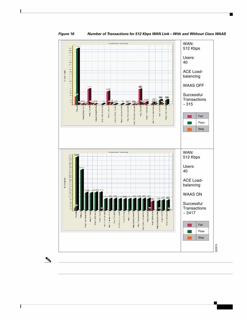
Figure 16 Number of Transactions for 512 Kbps WAN Link—With and Without Cisco WAAS
2228
15
WAN: 512 Kbps
Users:40
ACE Load-balancing
WAAS OFF
Successful Transactions~ 315
Fail
Pass
Stop
Fail
Pass
Stop
WAN: 512 Kbps
Users:40
ACE Load-balancing
WAAS ON
Successful Transactions~ 2417
Network Management
Network Management
•
•
•
•
•
•
•
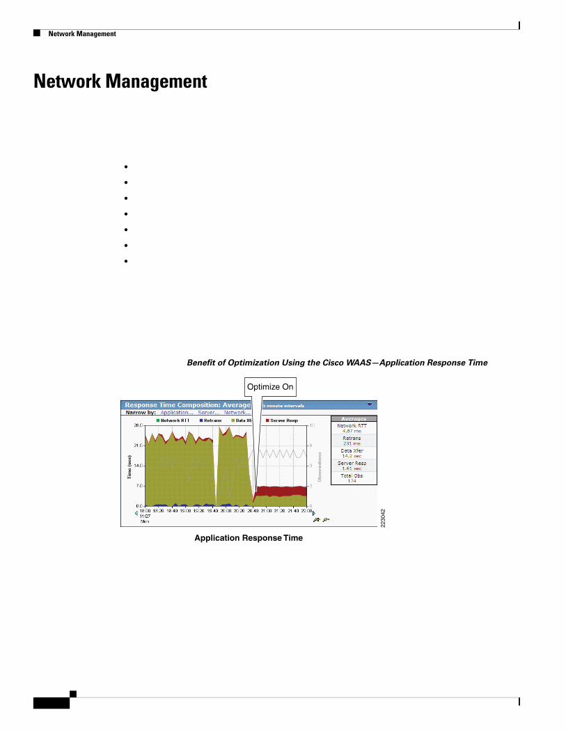
Benefit of Optimization Using the Cisco WAAS—Application Response Time
Application Response Time
2230
42Optimize On
Appendix A—Cisco ACE Configuration
Appendix A—Cisco ACE Configuration
Cisco ACE Admin Context
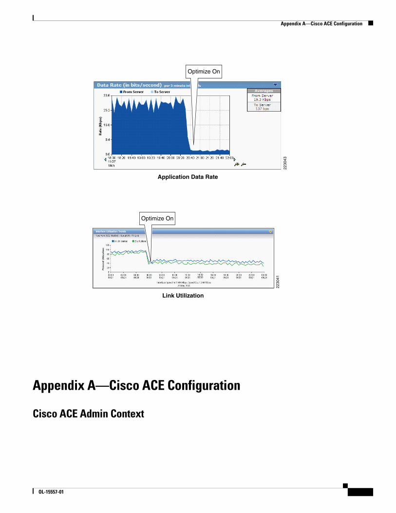
Application Data Rate
2230
43
Optimize On
Link Utilization
Optimize On
2230
41
OL-15557-01

Appendix A—Cisco ACE Configuration
OL-15557-01
Appendix A—Cisco ACE Configuration
Cisco ACE WebLogic Context
OL-15557-01

Appendix A—Cisco ACE Configuration
OL-15557-01
Appendix B—Cisco WAE Configurations
Appendix B—Cisco WAE Configurations
Branch Cisco WAE Configuration
OL-15557-01

Appendix B—Cisco WAE Configurations
OL-15557-01
Appendix B—Cisco WAE Configurations
Data Center Cisco WAE Configuration
OL-15557-01

Appendix B—Cisco WAE Configurations
OL-15557-01
Appendix C—Implementing and Configuring the ACE Appliance Solution
Appendix C—Implementing and Configuring the ACE Appliance Solution
Implementation
What Was Implemented
•
•
•
•
•
What Was Not Implemented/Tested
•
•
OL-15557-01
Appendix C—Implementing and Configuring the ACE Appliance Solution
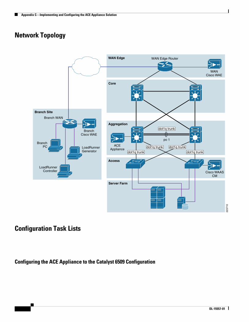
Network Topology
Configuration Task Lists
Configuring the ACE Appliance to the Catalyst 6509 Configuration
BranchPC
Access
Aggregation
WAN Edge
Core
Branch Site
WAN Edge Router
Branch WAN
WANCisco WAE
LoadRunnerGenerator
LoadRunnerController
BranchCisco WAE
Cisco WAASCM
dot1q trunk
po 1
dot1q trunk
dot1q trunk dot1q trunk
dot1q trunk
Server Farm
2237
10
ACEAppliance
OL-15557-01

Appendix C—Implementing and Configuring the ACE Appliance Solution
Step 1
Step 2
OL-15557-01
Appendix C—Implementing and Configuring the ACE Appliance Solution
Step 3
Results and Conclusions
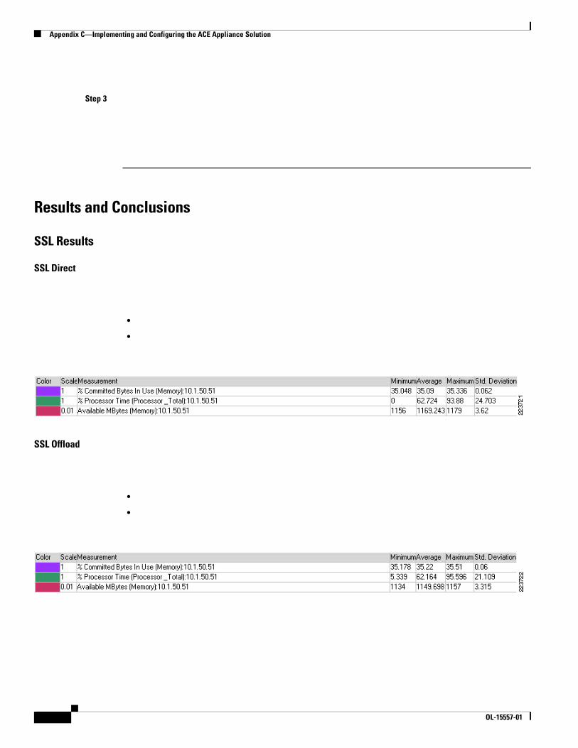
SSL Results
SSL Direct
•
•
SSL Offload
•
•
OL-15557-01
Appendix C—Implementing and Configuring the ACE Appliance Solution
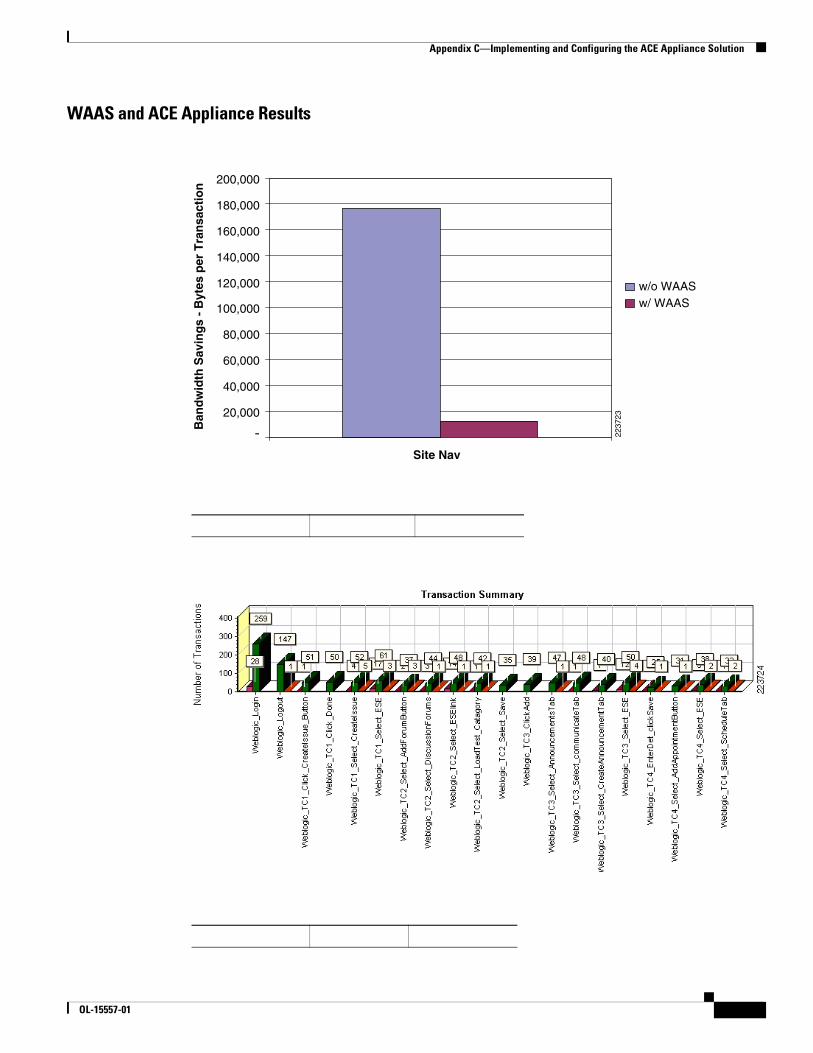
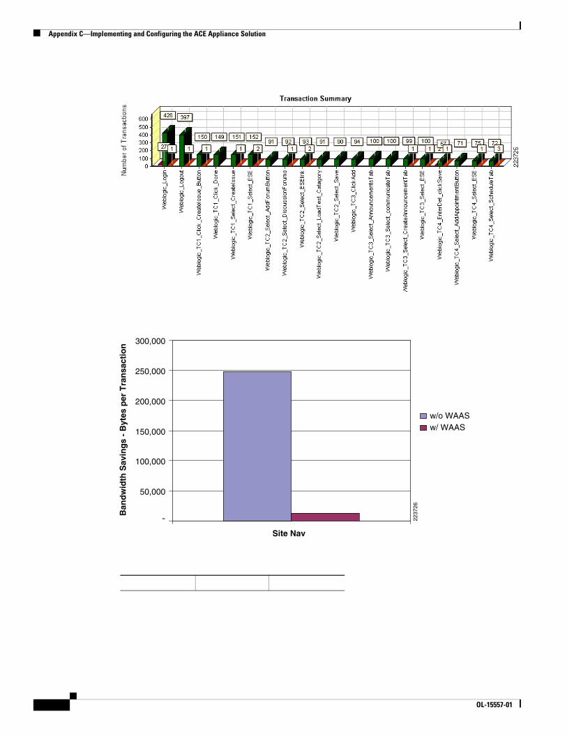
WAAS and ACE Appliance Results
2237
23
-
200,000
Site Nav
Ban
dw
idth
Sav
ing
s -
Byt
es p
er T
ran
sact
ion
w/o WAASw/ WAAS
180,000
160,000
140,000
120,000
100,000
80,000
60,000
40,000
20,000
OL-15557-01
Appendix C—Implementing and Configuring the ACE Appliance Solution
2237
26
-
300,000
Site Nav
Ban
dw
idth
Sav
ing
s -
Byt
es p
er T
ran
sact
ion
w/o WAASw/ WAAS
250,000
200,000
150,000
100,000
50,000
OL-15557-01
Appendix D—References
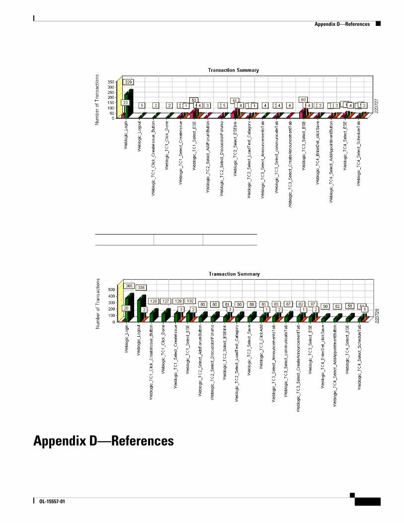
Appendix D—References
OL-15557-01
Cisco Validated Design
Cisco Advanced Services
Cisco Services Help Accelerate and Optimize ANS Deployments
•
•
•
•
•
Cisco Validated Design
(COLLECTIVELY, "DESIGNS") IN THIS MANUAL ARE PRESENTED "AS IS," WITH ALL FAULTS. CISCO AND ITS SUPPLIERS DISCLAIM ALL WARRANTIES, INCLUDING, WITHOUT LIMITATION, THE WARRANTY OF MERCHANTABILITY, FITNESS FOR A PARTICULAR PURPOSE AND NONINFRINGEMENT OR ARISING FROM A COURSE OF DEALING, USAGE, OR TRADE PRACTICE. IN NO EVENT SHALL CISCO OR ITS SUPPLIERS BE LIABLE FOR ANY INDIRECT, SPECIAL, CONSEQUENTIAL, OR INCIDENTAL DAMAGES, INCLUDING, WITHOUT LIMITATION, LOST PROFITS OR LOSS OR DAMAGE TO DATA ARISING OUT OF THE USE OR INABILITY TO USE THE DESIGNS, EVEN IF CISCO OR ITS SUPPLIERS HAVE BEEN ADVISED OF THE POSSIBILITY OF SUCH DAMAGES.
THE DESIGNS ARE SUBJECT TO CHANGE WITHOUT NOTICE. USERS ARE SOLELY RESPONSIBLE FOR THEIR APPLICATION OF THE DESIGNS. THE DESIGNS DO NOT CONSTITUTE THE TECHNICAL OR OTHER PROFESSIONAL ADVICE OF CISCO, ITS
OL-15557-01
Cisco Validated Design
SUPPLIERS OR PARTNERS. USERS SHOULD CONSULT THEIR OWN TECHNICAL ADVISORS BEFORE IMPLEMENTING THE DESIGNS. RESULTS MAY VARY DEPENDING ON FACTORS NOT TESTED BY CISCO.
CCDE, CCENT, Cisco Eos, Cisco Lumin, Cisco Nexus, Cisco StadiumVision, Cisco TelePresence, the Cisco logo, DCE, and Welcome to the Human Network are trademarks; Changing the Way We Work, Live, Play, and Learn and Cisco Store are service marks; and Access Registrar, Aironet, AsyncOS, Bringing the Meeting To You, Catalyst, CCDA, CCDP, CCIE, CCIP, CCNA, CCNP, CCSP, CCVP, Cisco, the Cisco Certified Internetwork Expert logo, Cisco IOS, Cisco Press, Cisco Systems, Cisco Systems Capital, the Cisco Systems logo, Cisco Unity, Collaboration Without Limitation, EtherFast, EtherSwitch, Event Center, Fast Step, Follow Me Browsing, FormShare, GigaDrive, HomeLink, Internet Quotient, IOS, iPhone, iQ Expertise, the iQ logo, iQ Net Readiness Scorecard, iQuick Study, IronPort, the IronPort logo, LightStream, Linksys, MediaTone, MeetingPlace, MeetingPlace Chime Sound, MGX, Networkers, Networking Academy, Network Registrar, PCNow, PIX, PowerPanels, ProConnect, ScriptShare, SenderBase, SMARTnet, Spectrum Expert, StackWise, The Fastest Way to Increase Your Internet Quotient, TransPath, WebEx, and the WebEx logo are registered trademarks of Cisco Systems, Inc. and/or its affiliates in the United States and certain other countries.
All other trademarks mentioned in this document or Website are the property of their respective owners. The use of the word partner does not imply a partnership relationship between Cisco and any other company. (0807R)
OL-15557-01

Cisco Validated Design
OL-15557-01