Cisco Aironet 1400 Series Wireless Bridge Mounting …conduits, bracing, cable trays, safety...
43
Corporate Headquarters: Copyright © 2005 Cisco Systems, Inc. All rights reserved. Cisco Systems, Inc., 170 West Tasman Drive, San Jose, CA 95134-1706 USA Cisco Aironet 1400 Series Wireless Bridge Mounting Instructions March 2005 Contents This document explains how to mount the Cisco Aironet 1400 Series Wireless Bridge and contains the following sections: • Introduction, page 2 • System Requirements, page 3 • Safety Precautions, page 3 • Choosing a Mounting Location, page 4 • Physical Site Inspection, page 5 • Required Tools and Fasteners, page 6 • Initial Lab Bring-Up, page 14 • Mounting the Bridge, page 21 • Routing the Cables, page 27 • Activating the Link, page 31 • Stacking Bridges, page 40 • Related Documentation, page 42 • Obtaining Documentation and Submitting a Service Request, page 42
Transcript of Cisco Aironet 1400 Series Wireless Bridge Mounting …conduits, bracing, cable trays, safety...
Cisco Aironet 1400 Series Wireless Bridge Mounting Instructions
March 2005
ContentsThis document explains how to mount the Cisco Aironet 1400 Series Wireless Bridge and contains the following sections:
• Introduction, page 2
• System Requirements, page 3
• Safety Precautions, page 3
• Choosing a Mounting Location, page 4
• Physical Site Inspection, page 5
• Required Tools and Fasteners, page 6
• Initial Lab Bring-Up, page 14
• Mounting the Bridge, page 21
• Routing the Cables, page 27
• Activating the Link, page 31
• Stacking Bridges, page 40
• Related Documentation, page 42
• Obtaining Documentation and Submitting a Service Request, page 42
Corporate Headquarters:
Copyright © 2005 Cisco Systems, Inc. All rights reserved.
Cisco Systems, Inc., 170 West Tasman Drive, San Jose, CA 95134-1706 USA

Introduction
IntroductionThe Cisco Aironet 1400 Series Wireless Bridge provides high-speed data links between buildings. Operating in the unlicensed UNII-3 band (5725 to 5825 MHz), the bridge provides 802.11a standard data rates of 6 to 54 Mbps. You can stack two bridges in point-to-point configurations to increase data throughput or to provide cold standby redundancy.
The Cisco Aironet 1400 Series Wireless Bridge is available with or without an integrated antenna. When using a bridge with an integrated antenna, you must choose a mounting location with a clear path to the remote antenna and orient the bridge so that the antenna is positioned for maximum signal strength. The mounting brackets in the installation kit have adjustment slots that facilitate the positioning process. When using a bridge without an integrated antenna, mount the bridge in a convenient location near the external antenna. Each external antenna has its own mounting instructions.
Note To meet regulatory restrictions, the bridge configuration with the antenna connector and the external antenna must be professionally installed.
Typical Bridge Installation ComponentsThe bridge is designed to be installed in an outdoor environment, typically, on a tower or a tall building. A typical bridge installation diagram is shown in Figure 1.
Figure 1 Typical Bridge Installation Diagram
Note Ground wires must comply with Sections 810 and 820 of the National Electrical Code and Section 54 of the Canadian Electrical Code.
Caution To ensure correct installation and grounding, install the bridge in compliance with your local and national electrical codes: National Fire Protection Association (NFPA) 70, National Electrical Code (U.S.); Canadian Electrical Code, Part I, CSA 22.1 (Canada); and if local or national electrical codes are not available, refer to IEC 364, Part 1 through 7 (other countries).
8883
6
Category 5Ethernet
cable
Dual-coaxcables
Dual-coaxcables
Indoor
Buildingentrance
Outdoor
Ground(see note)
Powerinjector
Powermodule
Groundingblock Bridge
Integratedor
external antenna
LAN network
2Cisco Aironet 1400 Series Wireless Bridge Mounting Instructions
OL-7618-01

System Requirements
Note In lightning environments, you should install lightning arrestors on each coax cable at the building entrance (see the “Grounding the Cables for Lightning Protection” section on page 28).
System RequirementsThe Cisco Aironet 1400 Series Wireless Bridge system consists of a weather-proof bridge, a Power Injector LR, a grounding block, and optional external antennas. The bridge and external antennas are typically mounted outdoors, the grounding block is installed at the building entrance, and the Power Injector LR and DC power supply are installed indoors. This document describes the bridge mounting procedures only. For information about other components, see the “Related Documentation” section on page 42.
Safety Precautions
Warning Do not install the antenna near overhead power lines or other electric light or power circuits, or where it can come into contact with such circuits. When installing the antenna, take extreme care not to come into contact with such circuits, as they may cause serious injury or death. For proper installation and grounding of the antenna, please refer to national and local codes (for example, U.S.:NFPA 70, National Electrical Code, Article 810, Canada:Canadian Electrical Code, Section 54.)
Warning Industry standards relating to radio frequency (RF) exposure limits for this product require that the antennas should be positioned no less than 6.6 feet (2 meters) from your body or nearby persons.
Each year hundreds of people are killed or injured when attempting to install an antenna. In many of these cases, the victim is aware of the danger of electrocution, but does not take adequate steps to avoid the hazard.
For your safety, and to help you properly install hardware, please read and follow these safety precautions. They may save your life!
1. If you are installing an antenna for the first time, for your own safety as well as others, seek assistance from a person with skills and knowledge related to the construction and operation of electrical equipment and has received safety training on the hazards involved.
2. Keep safety as well as performance in mind when selecting your installation site Remember: electric power lines and phone lines look alike. Always assume that overhead lines are very dangerous.
3. Call your electric power company. Tell them your plans, and ask them to look at your proposed installation. This is a reasonable request considering the danger.
4. Plan your installation carefully and completely before you begin. Successful raising of a mast or tower is largely a matter of coordination. Assign each person a specific task, and ensure they know what to do and when to do it. Put one person in charge of the operation to issue instructions and watch for signs of trouble.
5. When installing your antenna, remember:
a. Do not use a metal ladder.
b. Do not work on a wet or windy day.
3Cisco Aironet 1400 Series Wireless Bridge Mounting Instructions
OL-7618-01

Choosing a Mounting Location
c. Do dress properly—shoes with rubber soles and heels, rubber gloves, long sleeved shirt or jacket.
6. If the assembly starts to fall, get away from it and let it fall. Remember, the antenna, mast, cable, and metal guy wires are excellent conductors of electrical current and may touch power lines.
7. If any part of the antenna system comes in contact with a power line, don’t touch it or try to remove it yourself. Call your local power company. They can remove it safely.
If an accident occurs with the power lines, call for qualified emergency help immediately.
Choosing a Mounting LocationChoosing a good mounting location for the bridge is important because it affects the reliability of the wireless link and maximum data rates it can support. The most important considerations are distance between bridges and clearance from obstacles.
Signal Path DistanceIn an environment without obstacles in the signal path, the maximum distance between bridges depends primarily on the type of antennas and the free space loss between them. Make sure your proposed mounting site is within range of the remote antenna. The bridge supports 54-Mbps data rates at distances of up to 7.8 miles and 6 Mbps at distances up to 15.5 miles when using the integrated 22.5-dBi antenna on both bridges. When using a 9-dBi omni antenna at the hub and an integrated 22.5-dBi antenna remotely, the bridge supports 54-Mbps at distances up to 2 miles. Cisco.com has a range calculation tool for outdoor bridges that helps you estimate the range for your specific installation. To access the tool go this URL: http://www.cisco.com/en/US/prod/collateral/wireless/ps5678/ps458/prod_technical_reference09186a00800a912a.xls.
Antenna PolarizationThe integrated antenna radiates and receives polarized radio signals. Polarization helps reduce interference because the antenna tends to reject cross-polarized signals from other sources. Therefore, you can solve some interference problems by changing the antenna polarization. For the link to operate correctly, two antennas at each end of the link must always be set for the same polarization, either vertical or horizontal.
The bridge mounting hardware accommodates either vertical or horizontal antenna polarization. For more information, see the “Assembling the Mounting Hardware” section on page 7.
Signal Path ClearanceA radio beam travels from one bridge to another in a straight line. Therefore, the path between the antennas must be free of major obstacles. The effects of obstacles and terrain, both along and near the path, have a significant bearing on the propagation of radio signals and can cause both interference and signal cancellation.
When choosing a site, consider the effects of the following common obstacles:
• Trees and large plants
4Cisco Aironet 1400 Series Wireless Bridge Mounting Instructions
OL-7618-01

Physical Site Inspection
A tree directly in the path can totally block the signal. With clearance above the trees there are usually no secondary effects, but you should allow for future tree growth.
• Man-made obstacles
A large round container such as a gas storage reservoir or water tower that is partially in the path causes some blocking. These obstacles may also reflect some energy, which can interfere with other receivers. Square or rectangular objects in or near the path have rectangular surfaces that can block and diffract signals over and around them.
• Earth surface
The earth surface also interferes with signals if the antenna is mounted to low. Mount the antenna just high enough to allow adequate clearance from the ground (see Table 1). Placing the bridge too high makes it susceptible to interference from other systems.
To determine how much clearance to leave around the signal path, use the following clearances as a guide:
Install the bridge or external antenna where obstacles along the propagation path, including the ground, are no closer than these values. For tower installations, you may need to climb the tower to the proposed mounting location to verify a clear path to the other site. If trees are in the line of signal propagation, leave extra clearance around them for future growth into the signal path and seasonal changes.
Physical Site InspectionPerform a visual inspection of the site to ascertain and document the physical characteristics of the site and to ensure that all requirements are met for the proper installation and operation of the system.
Contact Information and Access PermissionsMake sure the following general issues are resolved before beginning the installation:
• Validate customer-provided information, such as site contact names and telephone numbers.
• Examine the building (tenant) lease to verify or establish building roof or tower rights. If available, use layout drawings to evaluate the feasibility of modifications or special permits that might be necessary.
• For a tower-mounted installation, determine if the owner, operator, or landlord requires a professional or certified tower climber to do the work.
Table 1 Clearance Guidelines for UNII 5.7-GHz Frequencies
Total Path Length (Miles) Clearance Radius Around Signal Path (feet)
4 30
6 37
8 42
10 47
12 52
15 58
5Cisco Aironet 1400 Series Wireless Bridge Mounting Instructions
OL-7618-01
Required Tools and Fasteners
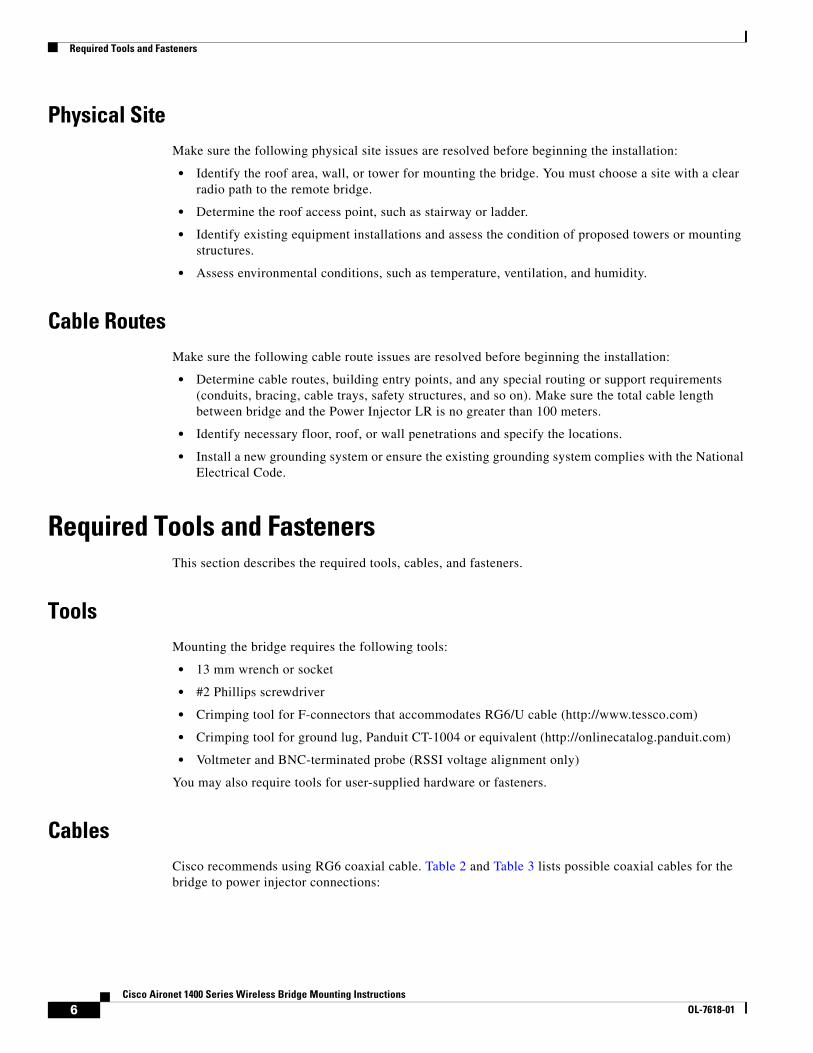
Physical Site Make sure the following physical site issues are resolved before beginning the installation:
• Identify the roof area, wall, or tower for mounting the bridge. You must choose a site with a clear radio path to the remote bridge.
• Determine the roof access point, such as stairway or ladder.
• Identify existing equipment installations and assess the condition of proposed towers or mounting structures.
• Assess environmental conditions, such as temperature, ventilation, and humidity.
Cable RoutesMake sure the following cable route issues are resolved before beginning the installation:
• Determine cable routes, building entry points, and any special routing or support requirements (conduits, bracing, cable trays, safety structures, and so on). Make sure the total cable length between bridge and the Power Injector LR is no greater than 100 meters.
• Identify necessary floor, roof, or wall penetrations and specify the locations.
• Install a new grounding system or ensure the existing grounding system complies with the National Electrical Code.
Required Tools and FastenersThis section describes the required tools, cables, and fasteners.
ToolsMounting the bridge requires the following tools:
• 13 mm wrench or socket
• #2 Phillips screwdriver
• Crimping tool for F-connectors that accommodates RG6/U cable (http://www.tessco.com)
• Crimping tool for ground lug, Panduit CT-1004 or equivalent (http://onlinecatalog.panduit.com)
• Voltmeter and BNC-terminated probe (RSSI voltage alignment only)
You may also require tools for user-supplied hardware or fasteners.
CablesCisco recommends using RG6 coaxial cable. Table 2 and Table 3 lists possible coaxial cables for the bridge to power injector connections:
6Cisco Aironet 1400 Series Wireless Bridge Mounting Instructions
OL-7618-01

Assembling the Mounting Hardware
Cisco Dual-Coax Cables
Table 2 lists the available Cisco RG-6 dual-coax cables.
Non-Cisco Coax Cables
Table 2 lists some available non-Cisco RG-6 coax cables.
Note The part numbers in Table 3 might change without notice. If this occurs, you should search the vendor website for the cable type.
FastenersIdentify requirements for special hardware or fasteners that are not supplied in the installation kit. For example, it might be necessary to secure the bridge to an unusually large diameter pipe or odd-shaped structural member that the supplied mounting bracket cannot accommodate. The rooftop support requires the following user-provided fasteners:
• Wooden structure — Four 1/4 x 2 inch (minimum) lag bolts
• Concrete structure — Four 1/4 x 1 inch (minimum) bolts with concrete anchors
A pole or tower mount requires guillotine-style U bolts that fits the pole or mast in use. One source is:
McMAC.CAR. For more information, see this company’s website.
Document all the necessary tools, parts, brackets, hardware and accessories that are required for the installation and make sure you have them all before starting.
Assembling the Mounting HardwareThe Cisco Aironet 1400 Series Wireless Bridge is shipped with mounting hardware that accommodates tower, mast, or rooftop installations. The mounting hardware comprises the following key parts:
• Rooftop mount (optional)
• Housing brackets
• Mounting bracket
Table 2 Cisco Dual-Coax Cables
Cable Length Cisco Part Number
20 ft (6.1 m) AIR-CAB020DRG6-F
50 ft (15.2 m) AIR-CAB05DRG6-F
100 ft (30.5 m) AIR-CAB100DRG6-F
Table 3 Non-Cisco Coaxial Cables
Cable Type Belden Part Number Times Fiber Part Number Channel Master Part Number
RG6 9077 2360-T660-VB or 2560-T690-VB 9539
7Cisco Aironet 1400 Series Wireless Bridge Mounting Instructions
OL-7618-01

Assembling the Mounting Hardware
Assembling the Rooftop MountThe optional rooftop or wall mount is used to mount your bridge to a flat horizontal or vertical surface, such as a building wall or roof. You must assemble the rooftop mount before you can use it. To assemble the mount, follow the instructions below:
Step 1 Place a washer on the long flanged hex bolt.
Step 2 Place the end of the mast pipe with the bolt holes into the mounting plate (see Figure 2).
Figure 2 Rooftop Support Bolt Locations
Step 3 Align the holes in the mast pipe with the holes in the mounting plate.
Step 4 Insert the long flanged hex bolt and washer into the upper holes on the mounting plate and through the mast pipe (see Figure 2).
Step 5 Place a washer and hex nut on the end of the long flanged hex bolt and hand-tighten.
Step 6 Position the mast pipe and mounting plate as shown in Figure 2.
Step 7 Align the lower square hole in the mast pipe with the semi-circular cut-out on the mounting plate.
Step 8 Place the carriage bolt into the square hole on the inside of the mast pipe.
Step 9 Place a washer and hex nut on the end of the carriage bolt and hand-tighten.
1 Long flanged hex bolt 3 Carriage bolt
2 Carriage bolt
8894
9
1
2
3
8Cisco Aironet 1400 Series Wireless Bridge Mounting Instructions
OL-7618-01

Assembling the Mounting Hardware
Step 10 Repeat Steps 8 and 9 for the other square hole.
You have completed the assembly of your rooftop or wall mount.
Attaching the Housing Brackets to the BridgeTo attach the housing brackets to the bridge, follow these steps:
Step 1 Find the polarization arrow on the back of the bridge housing. Rotate the bridge until the arrow points to the top for vertical polarization or to the right for horizontal polarization.
Note External bridge installations should use vertical polarization.
Figure 3 Housing Bracket Attachment
1 Housing bracket 4 Hang pin
2 Lock washer 5 Polarization arrow
3 Hex bolt
4
1
2
3
5
12
391
496
AN
TE
NN
AP
OL
AR
IZAT
ION
9Cisco Aironet 1400 Series Wireless Bridge Mounting Instructions
OL-7618-01

Assembling the Mounting Hardware
Step 2 Attach the housing brackets to the housing using four hex bolts and lock washers. Torque bolts to 14 to 16 ft. lb.
Note Make sure the hang pin faces outward for each housing bracket.
Attaching the Mounting BracketThe mounting bracket is suitable for rooftop, mast, or tower supports. How you attach the mounting bracket to the support depends on the mast diameter (see Table 4).
Rooftop Support or Small Mast Diameters
Use this procedure to attach the mounting bracket (see Figure 4) to the rooftop support or to a mast with a diameter between 1.25 and 2.5 inches (30.5 to 63.5 mm). For masts other than the rooftop support, use U bolts that fit the mast in use.
To attach the mounting bracket to the rooftop support or small mast, follow these steps:
Step 1 Position the mounting bracket next to the mounting pole so that the arrow on the bracket points up.
Table 4 Mounting Bracket Attachment
Mast Type Mast Diameter Mast Attachment
Rooftop supportor small mast
1.25 to 2.5 in. (30.5 to 63.5 mm)
Attach the mast to the mounting bracket between the bracket and bridge (see Figure 4)
Large Mast 2.5 to 4.5 in.(63.5 to 115 mm)
Attach the mast outside the mounting bracket away from the bridge (see Figure 5)
10Cisco Aironet 1400 Series Wireless Bridge Mounting Instructions
OL-7618-01

Assembling the Mounting Hardware
Figure 4 Mounting Bracket Assembly for Rooftop Support
Step 2 Attach the mounting bracket to the mast using two U bolts and four nuts and washers.
Note If you are using the integrated antenna, loosely tighten the U bolts so you can adjust the antenna horizontally for antenna positioning.
Large Mast Diameters
Use this procedure to attach the mounting bracket (see Figure 5) to masts with diameters from 2.5 to 4.5 inches (63.5 to 115 mm). This procedure requires customer-supplied guillotine U bolts that fit the mast in use.
1 U bolt 4 Hex nut
2 Mounting bracket 5 Roof mounting mast
3 Flat washer 6 Hang pin slot
1
6
5
2
34
9149
5
MOUNTUP
015
15
11Cisco Aironet 1400 Series Wireless Bridge Mounting Instructions
OL-7618-01

Assembling the Mounting Hardware
To attach the mounting bracket to a large mast, follow these steps:
Step 1 Position the mounting bracket next to the mast such that the arrow on the bracket points up.
Figure 5 Mounting Bracket Assembly for a Large Mast
Step 2 Attach the mounting bracket to the pole using two guillotine-style U bolts and four hex nuts. Be sure to use U bolts that fit the mast in use.
Note If you are using the integrated antenna, loosely tighten the U bolts so you can move the antenna horizontally to position it.
Attaching the Bridge to the Mounting BracketTo attach the bridge to the mounting bracket, follow these steps:
Step 1 Attach the bridge housing bracket to the mounting bracket by sliding the hang pins on the housing bracket into the hang pin slots on the mounting bracket. The connectors should face downward for vertical polarization (See Figure 6).
1 Guillotine-style U bolt (user supplied).See http://www.mcmaster.com
2 Large mast, 2.5 to 4.5 inches(63.5 to 115 mm) in diameter
1
288
749
MOUNTUP
015
15
12Cisco Aironet 1400 Series Wireless Bridge Mounting Instructions
OL-7618-01

Assembling the Mounting Hardware
Figure 6 Attaching the Bridge to the Mounting Bracket
Step 2 Secure the housing bracket to the mounting bracket with four hex bolts, split lock washers, and flat washers.
Note If you are using the integrated antenna, loosely tighten the bolts so you can move the antenna horizontally to position it.
Step 3 Roughly position the integrated antenna by pointing the flat face of the bridge toward the site of the remote bridge.
1 Hex bolt
2 Lock washer
3 Flat washer
32
1
3
21
9149
7
MOUNTUP
015
15
13Cisco Aironet 1400 Series Wireless Bridge Mounting Instructions
OL-7618-01
Initial Lab Bring-Up
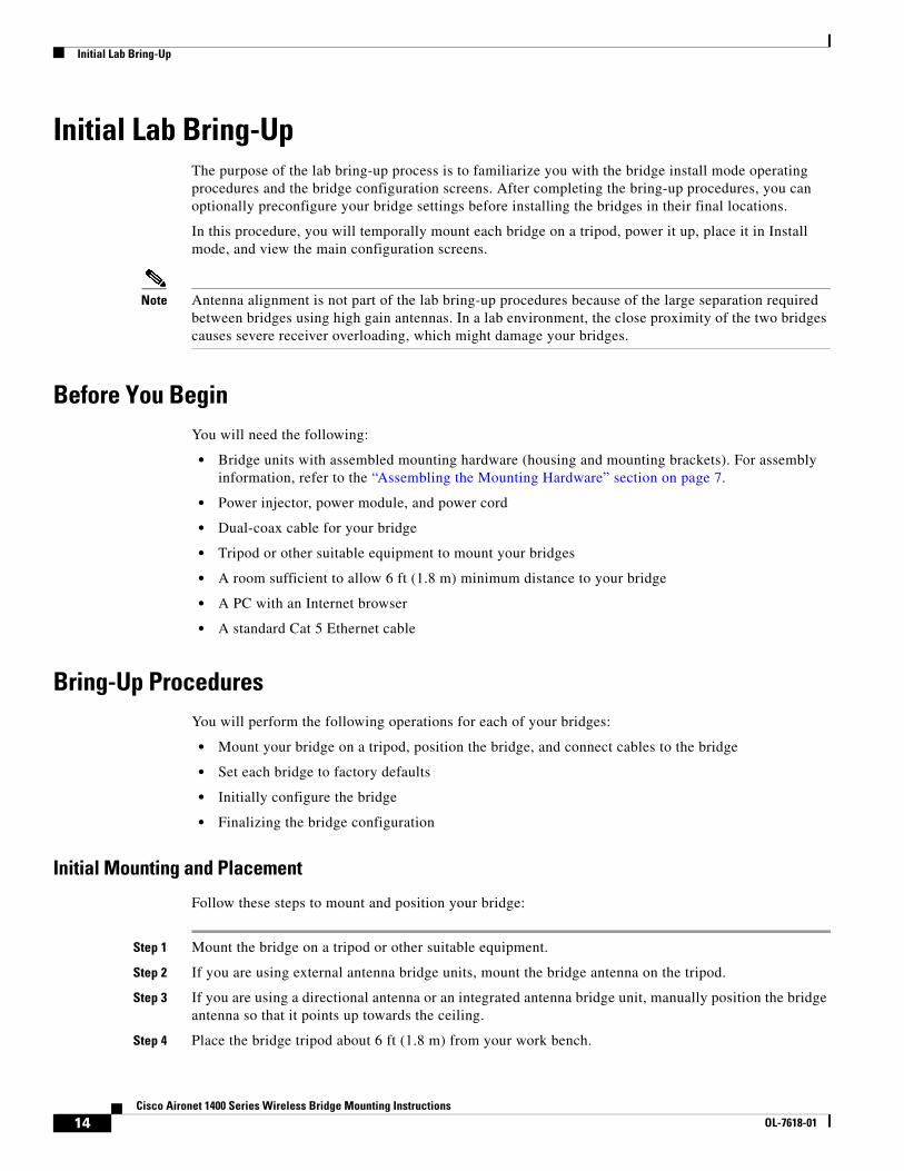
Initial Lab Bring-Up The purpose of the lab bring-up process is to familiarize you with the bridge install mode operating procedures and the bridge configuration screens. After completing the bring-up procedures, you can optionally preconfigure your bridge settings before installing the bridges in their final locations.
In this procedure, you will temporally mount each bridge on a tripod, power it up, place it in Install mode, and view the main configuration screens.
Note Antenna alignment is not part of the lab bring-up procedures because of the large separation required between bridges using high gain antennas. In a lab environment, the close proximity of the two bridges causes severe receiver overloading, which might damage your bridges.
Before You BeginYou will need the following:
• Bridge units with assembled mounting hardware (housing and mounting brackets). For assembly information, refer to the “Assembling the Mounting Hardware” section on page 7.
• Power injector, power module, and power cord
• Dual-coax cable for your bridge
• Tripod or other suitable equipment to mount your bridges
• A room sufficient to allow 6 ft (1.8 m) minimum distance to your bridge
• A PC with an Internet browser
• A standard Cat 5 Ethernet cable
Bring-Up ProceduresYou will perform the following operations for each of your bridges:
• Mount your bridge on a tripod, position the bridge, and connect cables to the bridge
• Set each bridge to factory defaults
• Initially configure the bridge
• Finalizing the bridge configuration
Initial Mounting and Placement
Follow these steps to mount and position your bridge:
Step 1 Mount the bridge on a tripod or other suitable equipment.
Step 2 If you are using external antenna bridge units, mount the bridge antenna on the tripod.
Step 3 If you are using a directional antenna or an integrated antenna bridge unit, manually position the bridge antenna so that it points up towards the ceiling.
Step 4 Place the bridge tripod about 6 ft (1.8 m) from your work bench.
14Cisco Aironet 1400 Series Wireless Bridge Mounting Instructions
OL-7618-01
Initial Lab Bring-Up
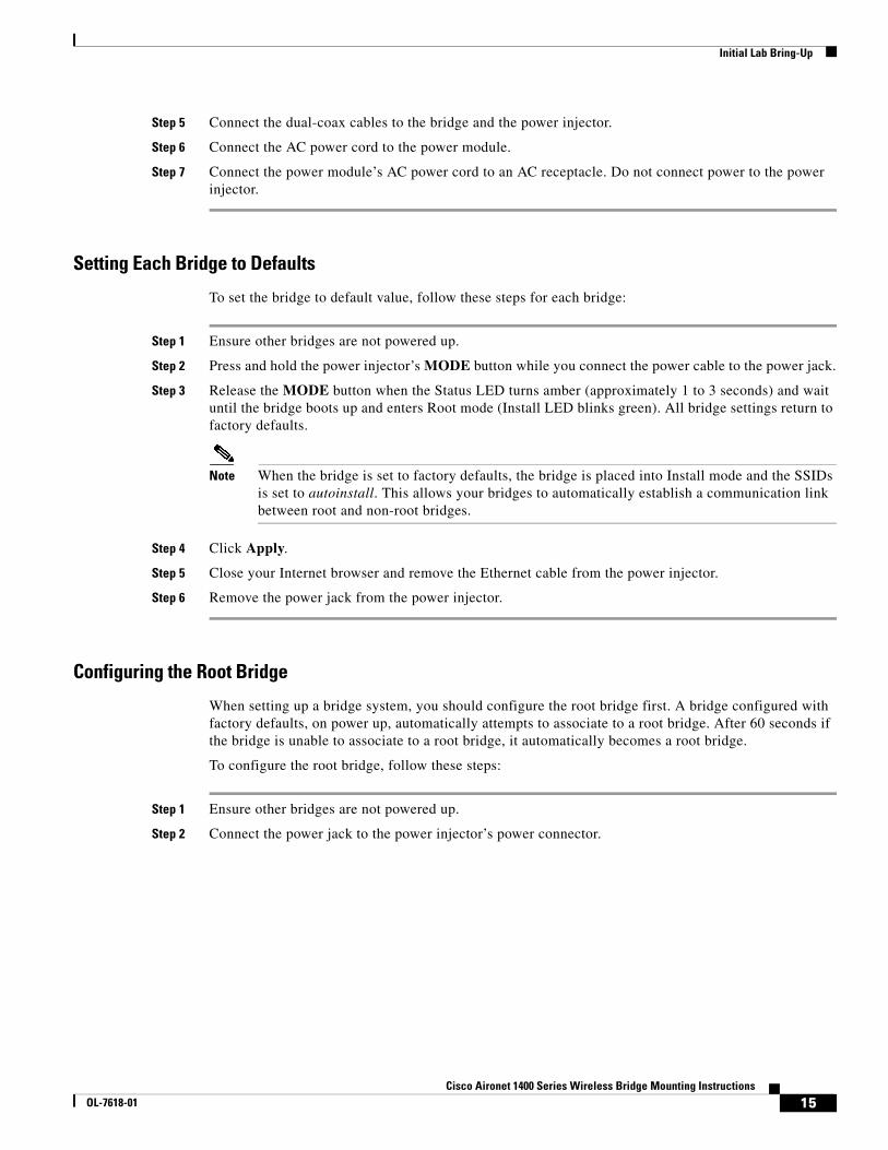
Step 5 Connect the dual-coax cables to the bridge and the power injector.
Step 6 Connect the AC power cord to the power module.
Step 7 Connect the power module’s AC power cord to an AC receptacle. Do not connect power to the power injector.
Setting Each Bridge to Defaults
To set the bridge to default value, follow these steps for each bridge:
Step 1 Ensure other bridges are not powered up.
Step 2 Press and hold the power injector’s MODE button while you connect the power cable to the power jack.
Step 3 Release the MODE button when the Status LED turns amber (approximately 1 to 3 seconds) and wait until the bridge boots up and enters Root mode (Install LED blinks green). All bridge settings return to factory defaults.
Note When the bridge is set to factory defaults, the bridge is placed into Install mode and the SSIDs is set to autoinstall. This allows your bridges to automatically establish a communication link between root and non-root bridges.
Step 4 Click Apply.
Step 5 Close your Internet browser and remove the Ethernet cable from the power injector.
Step 6 Remove the power jack from the power injector.
Configuring the Root Bridge
When setting up a bridge system, you should configure the root bridge first. A bridge configured with factory defaults, on power up, automatically attempts to associate to a root bridge. After 60 seconds if the bridge is unable to associate to a root bridge, it automatically becomes a root bridge.
To configure the root bridge, follow these steps:
Step 1 Ensure other bridges are not powered up.
Step 2 Connect the power jack to the power injector’s power connector.
15Cisco Aironet 1400 Series Wireless Bridge Mounting Instructions
OL-7618-01

Initial Lab Bring-Up
Step 3 Observe the LED status indications (refer to Table 5).
When the Install LED begins to blink amber, your bridge is attempting to connect to a remote root bridge.
In this procedure, your bridge will not locate a root bridge and becomes a root bridge (after 60 seconds) as indicated by the Install LED blinking green. When the Install LED blinks green, your bridge is sending beacons and waiting for a non-root bridge to associate.
Step 4 Using a Cat 5 Ethernet cable, connect your PC to the power injector’s Ethernet port.
Step 5 Configure your PC to receive an IP address using a DHCP server.
Step 6 Turn your PC off and on. Because your bridge is in Install mode, your PC receives an IP address from the bridge’s internal DHCP server.
Step 7 Activate your Internet browser and browse to the IP address of your bridge (10.0.0.1 is the default value). An Enter Network Password window appears.
Step 8 Enter your username in the User Name field. The default username is Cisco.
Step 9 Enter the bridge password in the Password field and press Enter. The default password is Cisco. The Summary Status page appears.
Step 10 Click Network Interfaces > Radio1-802.11A and the radio setup page displays.
Step 11 Click Settings and the radio settings page appears.
Step 12 Click Root and check Install Mode in the Role in Radio Network field.
When you manually configure the bridge as root and check Install Mode, the bridge provides RSSI LED indications for antenna alignment but does not search for another root bridge on power up.
Table 5 Install Mode LED Status Indications
Install LED Ethernet LED Status LED Radio LED Description
– Green Green Green Loading flash memory (part of POST operations)
– Amber Amber Amber Loopback test (part of POST operations)
– – Green – POST operations completed successfully
Blinking Amber
– – Blinking Amber
Searching for a root bridge. The non-root bridge attempts to associate with a root bridge for 60 seconds1.
1. If your bridge is preconfigured as a non-root bridge, it search indefinitely for the root bridge.
Blinking Amber
2
2. The Radio, Status, and Ethernet LEDs cycle through a simulated RSSI pattern ranging from off, slow blinking amber, medium blinking amber, fast blinking amber, and amber colors. The simulated RSSI pattern repeats twice.
2 2 Receive signal strength indication (RSSI) demonstration pattern (repeats twice).
Note This only occurs when a bridge is configured with factory defaults and if a root bridge is not detected.
Amber 3
3. The Radio, Status, and Ethernet LEDs indicate the RSSI signal level from the root bridge
3 3 Non-root mode and associated to a root bridge. For additional information on RSSI LED values, refer to Table 8.
Blinking Green
– – – Root mode, waiting for a non-root bridge to associate. The bridge waits indefinitely for a non-root bridge to associate.
Green 4
4. The Radio, Status, and Ethernet LEDs indicate the RSSI signal level from the non-root bridge
4 4 Root mode and non-root bridge associated. For additional information on RSSI LED values, refer to Table 8.
16Cisco Aironet 1400 Series Wireless Bridge Mounting Instructions
OL-7618-01
Initial Lab Bring-Up
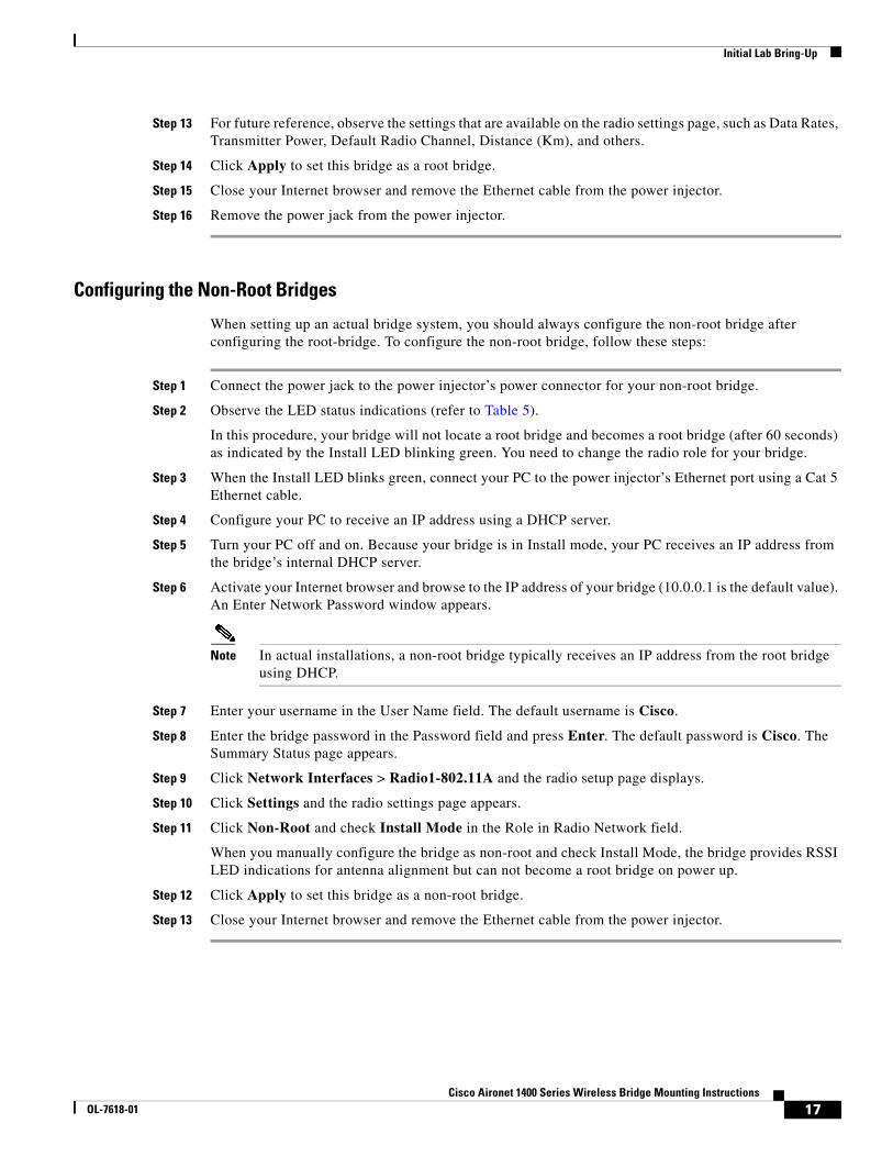
Step 13 For future reference, observe the settings that are available on the radio settings page, such as Data Rates, Transmitter Power, Default Radio Channel, Distance (Km), and others.
Step 14 Click Apply to set this bridge as a root bridge.
Step 15 Close your Internet browser and remove the Ethernet cable from the power injector.
Step 16 Remove the power jack from the power injector.
Configuring the Non-Root Bridges
When setting up an actual bridge system, you should always configure the non-root bridge after configuring the root-bridge. To configure the non-root bridge, follow these steps:
Step 1 Connect the power jack to the power injector’s power connector for your non-root bridge.
Step 2 Observe the LED status indications (refer to Table 5).
In this procedure, your bridge will not locate a root bridge and becomes a root bridge (after 60 seconds) as indicated by the Install LED blinking green. You need to change the radio role for your bridge.
Step 3 When the Install LED blinks green, connect your PC to the power injector’s Ethernet port using a Cat 5 Ethernet cable.
Step 4 Configure your PC to receive an IP address using a DHCP server.
Step 5 Turn your PC off and on. Because your bridge is in Install mode, your PC receives an IP address from the bridge’s internal DHCP server.
Step 6 Activate your Internet browser and browse to the IP address of your bridge (10.0.0.1 is the default value). An Enter Network Password window appears.
Note In actual installations, a non-root bridge typically receives an IP address from the root bridge using DHCP.
Step 7 Enter your username in the User Name field. The default username is Cisco.
Step 8 Enter the bridge password in the Password field and press Enter. The default password is Cisco. The Summary Status page appears.
Step 9 Click Network Interfaces > Radio1-802.11A and the radio setup page displays.
Step 10 Click Settings and the radio settings page appears.
Step 11 Click Non-Root and check Install Mode in the Role in Radio Network field.
When you manually configure the bridge as non-root and check Install Mode, the bridge provides RSSI LED indications for antenna alignment but can not become a root bridge on power up.
Step 12 Click Apply to set this bridge as a non-root bridge.
Step 13 Close your Internet browser and remove the Ethernet cable from the power injector.
17Cisco Aironet 1400 Series Wireless Bridge Mounting Instructions
OL-7618-01
Initial Lab Bring-Up
Finalizing Bridge Configurations
After completing the lab setup procedures, you can optionally completely configure your bridges before placing them at their final destinations. You should also ensure the bridges are set to Install mode to allow antenna alignment when they are installed.
Note After your bridges are installed in their final destinations and their antennas are aligned, you must exit Install mode by clicking Root or Non-Root (as appropriate) and unchecking Install Mode in all bridges (root and non-root). Exiting Install mode is required because a bridge left in Install mode can interfere with other bridge installations and prevents the transfer of data traffic through your bridge.
In Install mode, the SSID is set to autoinstall. When you exit Install mode, the SSID is automatically set to tsunami.
Note In actual installations, you should change the SSID from the default value and also configure appropriate security settings. You should also record the actual IP addresses for your root and non-root bridges.
Finding Non-Root Bridge IP Addresses
To obtain the IP addresses for the non-root bridges, follow these steps from your root bridge:
Step 1 Using a Cat 5 Ethernet cable, connect your PC to the root bridge power injector’s Ethernet port.
Step 2 Activate your Internet browser and browse to the IP address (default of 10.0.0.1) of your root bridge. An Enter Network Password window appears.
Step 3 Enter your username in the User Name field. The default username is Cisco.
Step 4 Enter the bridge password in the Password field and press Enter. The default password is Cisco. The Summary Status page appears.
Step 5 Click Association and the Association page appears.
Step 6 Record the names, IP addresses, and MAC addresses for each associated non-root bridge.
Note In actual installations, you should assign a descriptive host name (or system name) for each bridge to allow quick identification.
Exiting Install Mode and Changing the SSID
When exiting Install mode or changing the SSID, you should reconfigure the remote non-root bridges before you change the root bridge.
Note When you exit Install mode or change the SSID on a bridge, the bridge will loose association with the remote bridge or bridges.
18Cisco Aironet 1400 Series Wireless Bridge Mounting Instructions
OL-7618-01
Initial Lab Bring-Up
The exit Install mode and change the SSID using your Internet browser, follow these steps:
Step 1 Using a Cat 5 Ethernet cable, connect your PC to the root bridge power injector’s Ethernet port.
Step 2 Activate your Internet browser and browse to the IP address of the non-root bridge. An Enter Network Password window appears.
Step 3 Enter your username in the User Name field. The default username is Cisco.
Step 4 Enter the bridge password in the Password field and press Enter. The default password is Cisco. The Summary Status page appears.
Step 5 Click Express Set-Up and the Express Set-Up page appears.
Note In actual installations, you can configure a descriptive host name (or system name) for the bridge on the Express Set-Up page.
Step 6 Enter the new SSID in the SSID field.
Step 7 Click Root or Non-Root as appropriate for the specific bridge being configured.
Step 8 Click Apply and then click Yes on the pop-up confirmation window.
Note The remote non-root bridge will loose association with the root bridge until the root bridge configuration is correspondingly changed.
Step 9 Go to the bridge and observe the Install mode LED. The Install mode LED should be off.
Note When the bridge is not in Install mode, the Radio, Status, and Ethernet LEDs operate normally and do not provide RSSI readings.
Step 10 Repeat Steps 1 to 8 for each non-root bridge and then the root bridge.
After you have changed the configurations on all your root and non-root bridges, the non-root bridges can again reassociate with the root bridge.
Configuring the Radio Distance Parameter
In Install mode, the bridge default distance setting is 99 km. In other modes, the default distance setting is 0 km. When you change the role from Install Mode to Root or Non-Root, the distance setting changes automatically from 99 km to 0 km, and you need to adjust the distance setting for your specific system.
Note If your bridge is running Cisco IOS Release 12.3(2)JA or earlier, the bridge distance setting can only be changed on the root bridge using Cisco IOS CLI commands.
The distance setting is used to specify the distance from a root bridge to the non-root bridges with which it communicates. The distance setting adjusts the bridge's timeout values to account for the time required for radio signals to travel from bridge to bridge. If more than one non-root bridge communicates with the root bridge, enter the distance from the root bridge to the non-root bridge that is farthest away. Enter a value from 0 to 99 km.
19Cisco Aironet 1400 Series Wireless Bridge Mounting Instructions
OL-7618-01
Initial Lab Bring-Up
If your bridge is running Cisco IOS Release 12.3(4)JA or later, follow these steps to use your Internet browser to configure the bridge distance setting:
Step 1 Using a Cat 5 Ethernet cable, connect your PC to the root bridge power injector’s Ethernet port.
Step 2 Activate your Internet browser and browse to the IP address of your bridge (10.0.0.1 is the default value). An Enter Network Password window appears.
Step 3 Enter your username in the User Name field. The default username is Cisco. The username case-sensitive.
Step 4 Enter the bridge password in the Password field and press Enter. The default password is Cisco. The password is case-sensitive. The Summary Status page appears.
Step 5 Click Network Interfaces > Radio1-802.11A and the radio setup page displays.
Step 6 Click Settings and the radio settings page appears.
Step 7 Enter the distance setting (0 to 99 km) in the Distance field.
Step 8 Click Apply.
Step 9 Close your internet browser.
Follow these steps to use Telnet and the bridge CLI to change the bridge distance setting:
Note These steps are for a PC running Microsoft Windows with a Telnet terminal application. Check your PC operating instructions for detailed instructions for your operating system.
Step 1 Using a Cat 5 Ethernet cable, connect your PC to the root bridge power injector’s Ethernet port.
Step 2 On your PC, select Start > Run, type Telnet in the entry field, and press Enter.
Step 3 When the Telnet window appears, click Connect and select Remote System.
Note In Windows 2000, the Telnet window does not contain drop-down menus. To start the Telnet session in Windows 2000, type open followed by the access point’s IP address.
Step 4 In the Host Name field, type the access point’s IP address and click Connect.
Step 5 At the username and password prompts, enter your administrator username and password. The default username is Cisco, and the default password is Cisco. Usernames and passwords are case-sensitive.
Step 6 Enter enable and press Enter.
Step 7 At the password prompt, enter the enable password. The default enable password is also Cisco. The password is case-sensitive.
Step 8 Enter configure terminal and press Enter.
Step 9 Enter interface dot11radio 0 and press Enter.
Step 10 Enter distance and a distance setting from 0 to 99 kilometers. Press Enter.
Step 11 Enter end and press Enter.
Step 12 Enter copy running-config startup-config and press Enter.
20Cisco Aironet 1400 Series Wireless Bridge Mounting Instructions
OL-7618-01
Mounting the Bridge
Mounting the BridgeThis section describes the mounting procedures for rooftop, mast, and tower installations. Personnel installing the bridge must understand wireless bridging techniques, antenna alignment and adjustment, and grounding methods. The integrated antenna configuration can be installed by an experienced IT professional, but the external antenna bridge configuration and the external antenna must be professionally installed.
Warning Industry standards relating to radio frequency (RF) exposure limits for this product require that the antennas should be positioned no less than 6.6 feet (2 meters) from your body or nearby persons.
These procedures focus on general mounting and cable-routing topics. For information about assembling the mounting hardware, see the “Assembling the Mounting Hardware” section on page 7.
Rooftop or Wall MountThe mounting kit has an optional rooftop mounting bracket that is suitable for flat roofs, sloping roofs, and exterior walls. Mounting the bridge on a rooftop or wall includes the following subtasks:
1. Mounting the bridge
2. Routing the cables
3. Activating the link
To mount the bridge on a rooftop or wall, follow these steps:
Step 1 Choose a mounting location for the bridge. If you are using the integrated antenna, the mounting location must provide a clear signal path to the remote bridge. For more information, see “Choosing a Mounting Location” section on page 4.
Step 2 Find a solid mounting position for the base bracket, such as a stud or main building member on a roof or external wall. It may be necessary to utilize a stud-finder to find wooden structural members.
Step 3 Assemble the rooftop mount. For more information, see the “Assembling the Rooftop Mount” section on page 8.
Step 4 Mount the rooftop bracket at the mounting location using the following user-provided hardware:
• Wooden structure — Four 1/4 x 2 inch (minimum) lag bolts
• Concrete structure — Four 1/4 x 1 inch (minimum) bolts with concrete anchors
21Cisco Aironet 1400 Series Wireless Bridge Mounting Instructions
OL-7618-01

Mounting the Bridge
Figure 7 shows the rooftop mast assembly:
Figure 7 Roof-Mount Mast
Make sure that the mounting pole is vertical. You can rotate the foot of the bracket to adjust the vertical position for wall or sloped-roof mounting locations.
Step 5 Tighten the bolts to secure the mounting pole to the mounting foot. Torque nuts to 12 to 14 ft. lb.
Step 6 Attach the bridge to the vertical section of the pole using the supplied brackets and hardware. For more information, see the “Attaching the Housing Brackets to the Bridge” section on page 9, “Attaching the Mounting Bracket” section on page 10, and “Attaching the Bridge to the Mounting Bracket” section on page 12.
Note The integrated antenna is polarized, so be sure to attach the bridge housing brackets so that the antenna polarization matches the remote antenna polarization.
8875
0
22Cisco Aironet 1400 Series Wireless Bridge Mounting Instructions
OL-7618-01

Mounting the Bridge
Figure 8 shows the bridge mounted on the rooftop mast:
Figure 8 Roof-Mount Assembly
Step 7 Point the antenna as accurately as possible in the direction of the remote antenna. The integrated antenna is correctly positioned when the flat surface of the plastic cover faces the remote antenna.
Step 8 Find the building's grounding electrode system and then connect the bridge ground lug to the building's grounding electrode system using 6 AWG copper wire. Use a crimping tool to crimp the wire to the ground lug.
Caution To ensure correct installation and grounding, install the bridge in compliance with your local and national electrical codes: National Fire Protection Association (NFPA) 70, National Electrical Code (U.S.); Canadian Electrical Code, Part I, CSA 22.1 (Canada); and if local or national electrical codes are not available, refer to IEC 364, Part I through Part 7 (other countries).
Note Local code may require grounding of the rooftop mount.
9149
4
23Cisco Aironet 1400 Series Wireless Bridge Mounting Instructions
OL-7618-01
Mounting the Bridge
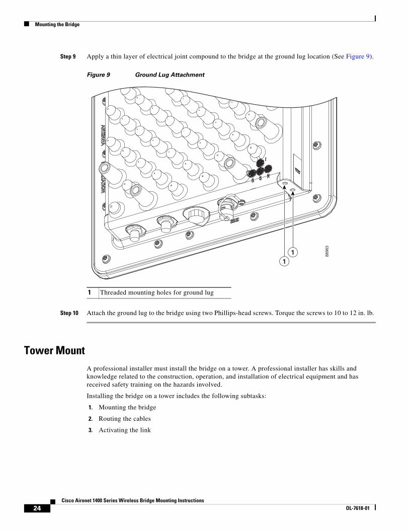
Step 9 Apply a thin layer of electrical joint compound to the bridge at the ground lug location (See Figure 9).
Figure 9 Ground Lug Attachment
Step 10 Attach the ground lug to the bridge using two Phillips-head screws. Torque the screws to 10 to 12 in. lb.
Tower MountA professional installer must install the bridge on a tower. A professional installer has skills and knowledge related to the construction, operation, and installation of electrical equipment and has received safety training on the hazards involved.
Installing the bridge on a tower includes the following subtasks:
1. Mounting the bridge
2. Routing the cables
3. Activating the link
1 Threaded mounting holes for ground lug
8896
3
11
24Cisco Aironet 1400 Series Wireless Bridge Mounting Instructions
OL-7618-01
Mounting the Bridge
Mounting the Bridge on a Tower
To mount the bridge on a tower, follow these steps:
Step 1 Choose a mounting location on the tower for the bridge. If you are using the integrated antenna, the mounting location must provide a clear signal path to the remote bridge. For more information, see “Choosing a Mounting Location” section on page 4.
Step 2 Find a suitable mounting support or install a mounting pole for the bridge. The mounting bracket accommodates poles from 1.25 to 4.5 inches (30.5 to 115 mm) in diameter; the supplied U bolts fit 1.25 to 1.75-inch poles only. You can find this type of hardware at http://www.tesco.com and http://www.rohnnet.com.
Step 3 Hoist the bridge assembly to the mounting location. The mounting brackets include hoist rings that can simplify this task. If you are hoisting a bridge that uses an external antenna, leave the foam block attached to the face of the bridge while hoisting to protect the N connector.
Step 4 Attach the bridge to the mounting pole using appropriate hardware. For more information, see the “Attaching the Housing Brackets to the Bridge” section on page 9, “Attaching the Mounting Bracket” section on page 10, and “Attaching the Bridge to the Mounting Bracket” section on page 12. The mounting bracket accommodates either a large mounting pole (see Figure 10) or small one (see Figure 8).
Note The integrated antenna is polarized, so be sure to attach the bridge housing brackets so that the antenna polarization matches the remote antenna polarization.
25Cisco Aironet 1400 Series Wireless Bridge Mounting Instructions
OL-7618-01

Mounting the Bridge
Figure 10 Bridge Attached to a Small Diameter Pole
Step 5 Point the antenna as accurately as possible in the direction of the remote antenna. The integrated antenna is correctly positioned when the flat face of the radome faces the remote antenna.
1 U bolt (supplied) 2 Small diameter pole, 1.25 to 2.5 inches (30.5 to 63.5 mm)
1
2
9149
8
26Cisco Aironet 1400 Series Wireless Bridge Mounting Instructions
OL-7618-01
Routing the Cables
Step 6 Connect the bridge ground lug to the tower (metal-to-metal) using 6 AWG copper wire. Use a crimping tool to crimp the ground lug to the wire.
Caution To ensure correct installation and grounding, install the bridge in compliance with your local and national electrical codes: National Fire Protection Association (NFPA) 70, National Electrical Code (U.S.); Canadian Electrical Code, Part I, CSA 22.1 (Canada); and if local or national electrical codes are not available, refer to IEC 364, Part I through Part 7 (other countries).
Step 7 Apply a thin layer of electrical joint compound to the bridge at the ground lug location (See Figure 9).
Step 8 Attach the ground lug to the bridge (see Figure 9) using two Phillips-head screws. Torque the screws to 10 to 12 in. lb.
Step 9 Ensure the tower is attached to a proper grounding system.
Routing the Cables
Cables to the Building Grounding BlockThis procedure explains how to route the cables from the power injector to the building grounding block. The grounding block should be installed at the building entry point and connected to the building’s ground system and every 100 ft (30 m) for long outside cable runs.
To route and connect cables, follow these steps:
Step 1 Unroll two 75-ohm cables the full length from the power injector to the building grounding block, laying them out straight without kinks.
Step 2 For unassembled cables, cut and install F-connectors on the ends of each cable.
Step 3 Connect the cables to the power injector.
Step 4 Secure the cables along the path from the power injector to the grounding block using UV-stabilized Ty-Wraps or equivalent fasteners.
Step 5 Form cable service loops and connect the cables to the grounding block.
Step 6 Find the building's grounding electrode system and then connect the grounding block to the building's grounding electrode system using 14 AWG copper wire or larger.
Caution To ensure correct installation and grounding, install the bridge in compliance with your local and national electrical codes: National Fire Protection Association (NFPA) 70, National Electrical Code (U.S.); Canadian Electrical Code, Part I, CSA 22.1 (Canada); and if local or national electrical codes are not available, refer to IEC 364, Part I through Part 7 (other countries).
Note In lightning environments, optional lightning arrestors should be installed at the building entrance (for additional information, see the “Grounding the Cables for Lightning Protection” section on page 28).
27Cisco Aironet 1400 Series Wireless Bridge Mounting Instructions
OL-7618-01

Routing the Cables
Step 7 Weather seal all external coaxial connectors by wrapping them with the sealant tape provided in the installation kit. For more information, see the “Applying Coax Seal Tape” section on page 29.
Note Do not weatherproof or permanently secure all connections until after final antenna alignment.
Grounding the Cables for Lightning ProtectionFor long outside cable runs, you must ground the shields of the RG6 coaxial cables to the tower at regular intervals. This precaution helps protect the bridge and the power injector from lightning damage. The recommended spacing between grounds is 100 ft (30 m). In areas of especially high lightning risk, space the grounds even closer. Make sure each grounding block makes good electrical (metal-to-metal) contact with the tower or a metal surface.
Caution Make sure to comply with the tower owner's policies and local codes. Drilling into tower structures or other alterations can affect the tower's long-term integrity.
In lightning environments, optional lightning arrestors (or protectors) should be installed for each coax cable at the building entrance. Mount the lightning arrestors at the building entrance and ground them in accordance with the manufacturer’s instructions. In very high lightning environments where arrestors with replaceable gas tubes are desired, use Huber+Suhner lightning arrestors (part number 3401.99.0022). In less severe lightning environments where lower cost, non-replaceable gas tube protectors are desired, NexTek lightning arrestors (PTC-C030) or equivalent can be used. For additional information on the lightning arrestors, see the websites of NexTek and Huber+Suhner.
Routing the CablesTo route and connect cables, follow these steps:
Step 1 For unassembled coax cables:
a. Unspool two 75-ohm cables, laying them out straight without kinks. Do not cut the cables until you know the required length between the bridge and the first grounding block and between each of the remaining grounding blocks.
Note Add an extra cable length for service loops at both ends.
b. Install F-connectors on the cable ends before climbing the tower.
Step 2 Tie a rope near the end of two cables, and secure it using black electrical tape, making sure the connectors do not support any cable weight.
Step 3 From the tower, use the rope to pull the cables up from the ground, making sure they pass along a tower member where they can be securely fastened.
Step 4 Connect the cables to the bridge connectors and install service loops (also called a drip loop). The cables should slope downward so that moisture runs away from the connectors during rainstorms.
28Cisco Aironet 1400 Series Wireless Bridge Mounting Instructions
OL-7618-01
Routing the Cables
Step 5 Secure the cables to the tower along the route to the grounding block using UV-stabilized Ty-Wraps or equivalent fasteners.
Step 6 Install service loops and connect the cables to the grounding block.
Step 7 Repeat steps 2 to 6 for each cable segment between grounding blocks, except in Step 2 you must connect the cables to the grounding block connectors.
Note The grounding blocks must be directly connected (metal-to-metal) to the tower.
Step 8 Weather seal all coaxial connectors by wrapping them with the sealant tape provided with the installation kit. For more information, see the “Applying Coax Seal Tape” section on page 29.
Applying Coax Seal TapeYou must weather seal all coax connections using the Coax-Seal tape provided in the mounting kit. Coax connections that are not properly sealed permit moisture to enter the connection, which leads to performance degradation or link problems.
The following connectors must be weather sealed:
• F-connectors, located at the bridge and each grounding block.
• N connector, when using the bridge with an external antenna.
Note Do not use conventional plastic electrical tape because it deteriorates during long-term exposure to ultraviolet light and extreme weather.
To apply Coax Seal, follow these steps:
Step 1 Make sure that the cables are secure and the F-connectors are tight. Torque the connectors to 10 to 14 in lbs.
Step 2 Make sure that the coaxial cable, F-connectors, and connector areas are clean and dry.
Step 3 Peel the paper backing off one of the 10 in. lengths of Coax-Seal tape.
29Cisco Aironet 1400 Series Wireless Bridge Mounting Instructions
OL-7618-01

Routing the Cables
Step 4 Wrap the F-connector with the tape, starting at the coaxial cable, extending across the connector body, and finishing close the bridge or grounding block. Overlap each turn at least 50 percent so there is a double thickness over all areas (see Figure 11).
Figure 11 Coax Seal Tape Application
Step 5 Using your fingers, mold and form the Coax-Seal around the cable and connector to form a smooth surface. Make sure to squeeze out any air pockets (see Figure 12).
Figure 12 Coax Seal Tape After Forming Into Shape
Step 6 Visually inspect the seal to make sure the entire connector area is completely covered. If gaps are visible, apply additional Coax-Seal over the existing material and then mold it to shape.
Step 7 Repeat this procedure for each coaxial connection on the bridge and grounding blocks.
9506
3
9506
2
30Cisco Aironet 1400 Series Wireless Bridge Mounting Instructions
OL-7618-01
Activating the Link
Activating the LinkActivate the link after the bridge system is completely installed and ready to power up. The following procedure summarizes the bridge activation procedure:
1. Power up the root bridge, observing the power injector and bridge LEDs to verify proper startup.
2. Power up the remote non-root bridge, verify successful association, and position the antenna.
3. Position the root antenna.
If the initial antenna positioning was reasonably accurate, both bridges initialize and quickly associate with one another. If the bridges do not associate, the antennas may be poorly aligned and you must adjust the antenna position during the bridge startup cycle. Persistent association problems can indicate poor placement of the bridge or obstacles in the transmission path.
Use LED indications to verify the state of the bridge during the association process. The following sections explains how to interpret LED indicators.
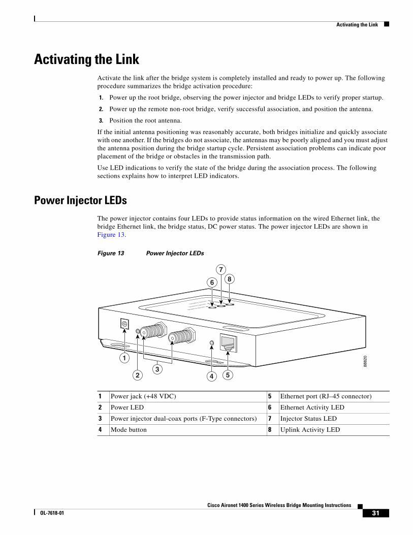
Power Injector LEDsThe power injector contains four LEDs to provide status information on the wired Ethernet link, the bridge Ethernet link, the bridge status, DC power status. The power injector LEDs are shown in Figure 13.
Figure 13 Power Injector LEDs
1 Power jack (+48 VDC) 5 Ethernet port (RJ–45 connector)
2 Power LED 6 Ethernet Activity LED
3 Power injector dual-coax ports (F-Type connectors) 7 Injector Status LED
4 Mode button 8 Uplink Activity LED
8882
01
2 4 5
87
6
3
Ipsamy opsumIpsamy opsumIpsamy opsum
31Cisco Aironet 1400 Series Wireless Bridge Mounting Instructions
OL-7618-01

Activating the Link
Checking Power Using Power Injector LEDs
When the power injector is powered up, it sends a constant discovery tone on the dual-coax cables to the bridge. When the bridge is connected to the dual-coax cables, it returns the discovery tone to the power injector. When the power injector detects the returned discovery tone, it applies +48 VDC to the dual-coax cables to the bridge.
You can verify the availability of power to the bridge by checking the power injector LEDs (see Figure 13):
• Power LED
– Green color indicates 48 VDC is available to the power injector (see Figure 13).
– Off indicates 48 VDC is not available to the power injector—verify that the power module is connected to the power injector and to an AC receptacle and that AC power is available.
• Uplink Activity LED
– Green or blinking green color indicates the bridge is operating.
– Off indicates that the power injector-to-bridge link is not active—verify that the dual-coax cable connections are properly connected to the power injector, the grounding block, and the bridge. If the dual-coax cable is connected properly and the cable is not defective, contact technical support for assistance.
– Amber color indicates that an internal power injector problem—disconnect and reconnect the power injector power plug. If the problem continues, contact technical support for assistance contact technical support for assistance.
• Status LED
– Green or blinking green color indicates that the bridge is operating.
– Blinking amber color indicates that the bridge has not been detected by the power injector and that power is not being supplied to the bridge—verify that the dual-coax cable connectors are properly connected to the power injector, the grounding block, and the bridge. If the dual-coax cable is connected properly and not defective, contact technical support for assistance.
Checking the Power Injector LEDs
When power is applied to the bridge, the bridge activates the bootloader and begins the POST operations. The bridge begins to load the IOS image when the Post operations are successfully completed. Upon successfully loading the IOS image, the bridge initializes and tests the radio. The power injector LED indications are listed in Table 6.
Table 6 Power Injector LED Indications
Uplink Activity Injector Status Ethernet Activity Description
— — Off Wired LAN Ethernet link is not active.
— — Green Wired LAN Ethernet link is operational.
— — Blinking Green Transmitting and receiving packets over the wired LAN Ethernet link.
— — Amber Power injector internal memory error—disconnect and reconnect the power injector power plug. If the problem continues, contact technical support for assistance.
32Cisco Aironet 1400 Series Wireless Bridge Mounting Instructions
OL-7618-01

Activating the Link
Off — — Link between power injector and bridge is not active. This might be caused by improper connections or a defective cable or connector. Verify that the dual-coax cables are connected correctly to the power injector, grounding block, and bridge. If the cables are connected correctly, contact technical support for assistance.
Green — — Link between power injector and bridge is operational.
Blinking Green — — Transmitting and receiving Ethernet packets between the power injector and the bridge.
Amber — — Power injector internal memory error—disconnect and reconnect the power injector power plug. If the problem continues, contact technical support for assistance.
— Green — Bridge successfully passed Power On Self Test (POST) and loaded the IOS image.
— Blinking Green — Bridge power is active and the bridge is loading IOS image or POST operation has started.
— Blinking Amber — Bridge has not been detected and bridge power is not active. This might be caused by bad connections or a defective cable or connector. Verify that the dual-coax cables are connected correctly to the power injector, grounding block, and bridge. If the cables are connected correctly, contact technical support for assistance.
Amber Amber Amber Power injector internal memory error—disconnect and reconnect the power injector power plug. If the problem continues, contact technical support for assistance.
Off Amber Off Bridge is resetting the configuration to defaults; mode button has been depressed more than 2 seconds but less than 20 seconds.
— Red — Image recovery mode, downloading new image; mode button pressed more than 20 seconds.
Red Red Red Power injector internal memory error—disconnect and reconnect the power injector power plug. If the problem continues, contact technical support for assistance.
Table 6 Power Injector LED Indications (continued)
Uplink Activity Injector Status Ethernet Activity Description
33Cisco Aironet 1400 Series Wireless Bridge Mounting Instructions
OL-7618-01

Activating the Link
Bridge Installation Mode IndicatorsWhen you power up the bridge for the first time, it starts in a special installation mode. In this mode, the LEDs indicate the startup status, operating mode, association status, and received signal strength. This information helps you activate the link and position the antenna while at the bridge mounting location.
The LEDs are mounted on the back of the housing near the connectors (see Figure 14).
Figure 14 LED and Connector Locations
The Install LED displays the following information:
1 Power Injector LR interfaces 4 Status LED
2 RSSI voltage port 5 Radio LED
3 Ethernet LED 6 Install LED
6
11
2
35
4
8877
7
Table 7 Install LED States During Startup and Association
Install LED Bridge State
Off Startup
Amber blinking Scanning for beacons, not associated (non-root mode)
Amber Associated (non-root mode)
34Cisco Aironet 1400 Series Wireless Bridge Mounting Instructions
OL-7618-01

Activating the Link
After association, the Ethernet, Status, and Radio LEDs indicate signal strength (see Table 8).
The startup and association sequence depends on the initial bridge configuration, as follows:
• Default—The bridge attempts to associate with a root bridge for 60 seconds, and then it attempts to associate with a non-root bridge. This timeout limits the amount of time you have to reposition the antenna at the non-root location.
• Preconfigured—The bridge attempts to associate with a remote bridge in the configured mode, either root or non-root. Because there are no timeouts, it is easier to reposition an antenna with poor initial antenna positioning.
The following procedures explain how to activate the root and non-root bridges for either default or preconfigured bridges.
Activating the Root BridgeTo activate the root bridge, follow these steps:
Step 1 Verify that the directional antenna or the face (radome) of the integrated antenna bridge points in the approximate direction of the remote bridge antenna. If the antenna is at a significant angle, use binoculars, satellite global positioning system (GPS), or reference objects to find the remote bridge or antenna, and then manually adjust the horizontal and vertical positions accordingly.
Step 2 Apply power and observe the bridge LEDs.
Step 3 Wait for the bridge to cycle through the following initialization states:
Note If the Install LED changes to continuous amber, the bridge incorrectly associated with another root bridge. Turn off the interfering root bridge and then restart this procedure.
Step 4 Leave the root bridge powered up and go to the non-root bridge to align it’s antenna (see the “Activating the Non-Root Bridge” section on page 36).
Green blinking Transmitting beacons, not associated (root mode)
Green Associated (root mode)
Table 7 Install LED States During Startup and Association
Install LED Bridge State
State Install LED Activity
Self test Off Power on self test.
Non-root, searching1
1. If your bridge is preconfigured as a root bridge, it skips this state.
Amber blinking The bridge attempts to associate with a root bridge for 60 seconds.
Root, searching Green blinking The bridge attempts to associate with a non-root bridge indefinitely.
35Cisco Aironet 1400 Series Wireless Bridge Mounting Instructions
OL-7618-01

Activating the Link
Activating the Non-Root BridgeTo activate and align the non-root bridge, follow these steps:
Step 1 Apply power and observe the bridge LEDs.
Step 2 Wait for the bridge to cycle through the following initialization and association states:
Step 3 If the Install LED starts blinking green, the non-root bridge failed to associate with the root bridge. Power cycle the bridge, wait for the Install LED to blink amber, and then slowly pan the directional antenna or bridge radome left to right or tilt it up and down until the Install LED changes to continuous amber. In the default configuration, you have only 60 seconds to achieve association.
Note If your bridge fails to detect the root bridge in the 60-second period, you can begin the detection process again by removing and reinserting the power plug in the power injector.
Note If your bridge detects the root bridge, the RSSI LEDs (Radio, Status, and Ethernet) do not display the demo RSSI pattern but display the actual signal strength received from the root bridge.
Note After the non-root bridge associates to the root bridge, it receives an IP address by DHCP from the root bridge. In Install mode the root bridge becomes a DHCP server for the non-root bridges. In actual installations, you should use your PC and record this new IP address.
Step 4 Align the non-root bridge antenna using LED indications or RSSI voltages. For more information, see the “Positioning the Integrated Antenna” section on page 37.
Step 5 After obtaining antenna alignment, tighten all bridge mounting bolts and apply coax-seal to the cable and antenna connectors (see the “Applying Coax Seal Tape” section on page 29).
Step 6 Leave the non-root bridge power up and return to the root bridge to align its antenna using LED indications or RSSI voltages. For more information, see the “Positioning the Integrated Antenna” section on page 37.
State Install LED Activity
Self test Off Power on self test.
Non-root, searching Amber blinking The bridge attempts to associate with a root bridge.
Non-root, associated Amber The bridge successfully associated with the root bridge.
36Cisco Aironet 1400 Series Wireless Bridge Mounting Instructions
OL-7618-01

Activating the Link
Positioning the Integrated AntennaThe goal when positioning the antenna is to align the local antenna for maximum signal strength. Measure signal strength using LED indications or the Received Signal Strength Indicator (RSSI) voltage. The LEDs are convenient to use and adequate for most installations. The RSSI voltage is more precise than the LEDs and better for complex installations, such as for stacked bridges.
Normally, you observe a single large peak as you pan the antenna across the signal path. However, if the antennas are not well-positioned during installation, you may observe two peaks of roughly equal amplitude. Think of the receive signal as a target (see Figure 15).
Figure 15 Signal Strength Target Showing Two-Peak Case
The target consists of concentric rings, with the strongest signal at the center, surrounded by a weak area, and then a moderately strong side lobe. As you scan across the signal, you can miss the strong center signal and encounter two peaks of roughly equal amplitude, as shown by the horizontal dashed line. If you position the antenna on one of these weaker peaks and subsequently adjust the vertical position, you miss the maximum signal area completely. Instead, you must locate the two peaks and center the antenna between the peaks. The vertical scan then crosses the center point where the signal level is maximum.
1 Medium signal level 3 Strong signal level
2 Weak signal level 4 Midpoint between peaks
Horizontal
Vertical
1
4
2
3
8875
2
37Cisco Aironet 1400 Series Wireless Bridge Mounting Instructions
OL-7618-01

Activating the Link
Positioning the Antenna Using LED Indications
You can position the integrated antenna using LEDs only after the bridge successfully associates with the remote bridge. In installation mode, the Install LED is continuous amber or green when the bridge has successfully associated. The Ethernet, status, and radio LEDs then display the receive signal strength indication (see Table 8).
When you are using LEDs to maximize the signal, adjust the antenna until as many LEDs as possible are on and the rest are blinking as fast as possible. With all three LEDS on, the signal is good enough to support the maximum data rate.
To position the antenna using the LED indicators, follow these steps:
Step 1 Verify that the Install LED is either continuous amber or green.
Step 2 Slowly pan the bridge to the left and right of the signal path, and watch for peaks in signal strength. Be sure to swing the antenna in an arc of 60 degrees to each side to ensure that the integrated antenna passes through the main and side lobes of the remote antenna.
Step 3 Return the bridge to the position where the signal is strongest, or in the case of two similar peaks, halfway between them.
Step 4 Secure the horizontal adjustment by tightening the U bolts on the mast. Torque the nuts to 6 to 8 ft. lb.
Step 5 Slowly tilt the bridge up and down, and watch for peaks in signal strength. Use the full vertical adjustment range of the mounting brackets.
Step 6 Return the bridge to the position where the signal is strongest, normally where all signal strength LEDs are on. If you are unable to turn on all LEDs, simply maximize the signal.
Table 8 Install Mode Receive Signal Strength Indication (RSSI) Display
Signal Level (dBm) Ethernet LED Status LED Radio LED
–44 or stronger On On On
–47 to –44 Fast blink1
1. Blinks once per second
On On
–50 to –47 Medium blink2
2. Blinks twice per second
On On
–53 to –50 Slow blink3
3. Blinks four times per second
On On
–54 to –53 Off On On
–57 to –54 Off Fast blink On
–60 to –57 Off Medium blink On
–63 to –60 Off Slow blink On
–66 to –63 Off Off On
–69 to –66 Off Off Fast blink
–72 to –69 Off Off Medium blink
–75 to –72 Off Off Slow blink
– 75 or weaker Off Off Off
38Cisco Aironet 1400 Series Wireless Bridge Mounting Instructions
OL-7618-01

Activating the Link
Step 7 Secure the vertical adjustment by tightening the four bolts that secure the housing bracket to the support bracket. Torque bolts to 14 to 16 ft. lb.
Positioning the Antenna Using the Received Signal Strength Indicator
The Received Signal Strength Indicator (RSSI) is a DC voltage that is proportional to the received signal level. The RSSI voltage is available whenever a signal is present regardless of the bridge mode (install or normal).
Note The RSSI sample rate is faster when the bridge is placed in Install mode.
The RSSI port is a female BNC connector on the housing (see Figure 14). The RSSI voltage increases linearly with signal level. Table 9 shows the RSSI voltage for selected signal levels.
The RSSI varies from 0 to 2.7 volts for signals between –90 and –20 dBm, respectively. The accuracy over temperature and component variations is ± 4 dB. You can use any convenient voltmeter with a probe terminated with a male BNC connector to position the antenna.
To position the antenna using the RSSI voltage, follow these steps:
Step 1 Remove the RSSI port cover and connect a voltmeter probe to the port. Use a probe terminated with a male BNC connector.
Note For faster RSSI response, you can temporarily place the bridge in Install mode.
Step 2 Slowly pan the bridge to the left and right of the signal path and monitor the RSSI voltage for peaks in signal strength. Be sure to swing the antenna in an arc of 60 degrees to each side to ensure that the antenna passes through the main and side lobes of the antenna.
Step 3 Return the bridge to the position where the signal is strongest, or in the case of two similar peaks, halfway between them.
Step 4 Secure the horizontal adjustment by tightening the U bolts on the mast. Torque the nuts to 6 to 8 ft. lb.
Table 9 RSSI Voltage Levels
Nominal Signal Level (dBm) RSSI Reading (Volts)
–20 or greater 2.7
–30 2.3
-40 1.9
–50 1.5
–60 1.2
–70 0.8
–80 0.4
–90 or less 0.0
39Cisco Aironet 1400 Series Wireless Bridge Mounting Instructions
OL-7618-01

Stacking Bridges
Step 5 Slowly tilt the bridge up and down, and watch for peaks in signal strength. Use the full vertical adjustment range of the mounting brackets.
Step 6 Return the bridge to the position where the signal level is strongest.
Step 7 Secure the vertical adjustment by tightening the four bolts that secure the housing bracket to the support bracket. Torque bolts to 14 to 16 ft. lb.
Step 8 Remove the cable from the RSSI port and replace the cover.
Stacking BridgesYou can double the throughput, or create a standby link, by stacking two bridges. A stacked installation consists of two bridge systems installed at the same physical location. For detailed mounting instructions refer to the Cisco Aironet 1400 Series Wireless Bridge Mounting Instructions that shipped with your bridge.
Operations summary:
• Adjacent bridges should be located at least 8 feet apart.
• Radios of adjacent bridges should be configured for operation on non-adjacent channels.
Choosing a Second Mounting LocationYou can mount the second bridge system in the same general location as the first as long as you separate the antennas by at least 8 feet. For example, in a flat-roof installation you can separate the bridges horizontally, roughly perpendicular to the line of signal propagation. In a tower installation, you can separate the antennas vertically. During the activation process, you verify that the interference between systems is acceptably low. Do not attempt to stack more than two bridges.
Figure 16 Interference Paths with Stacked Bridges
9500
8
Brdge BLink 2
Link 1
Site 1 Site 2
Interference path
Brdge A
Brdge D
Brdge C
40Cisco Aironet 1400 Series Wireless Bridge Mounting Instructions
OL-7618-01

Stacking Bridges
Installing the Stacked BridgesTo install stacked bridges, refer to Figure 16 as you follow these steps:
Step 1 Install the link 1 bridges (bridges A and C) normally, but leave room at each site to install the link 2 bridges (bridges B and C).
Step 2 Activate the link 1 bridges, align the antennas, and verify proper operation of the link.
Step 3 At each site location, choose a candidate location for the second bridge that is at least 8 feet away from the first bridge. Separate the bridges as far as is practical from each other, keeping in mind that the second antenna must have a clear path to the remote system.
Step 4 At each site location, temporarily install the second link 2 bridge, positioning the antenna toward the intended location of the corresponding link 2 remote antenna.
Note You can improve system isolation by using different polarizations for the two local antennas. For example, if the link 1 system has vertical polarization, assemble the link 2 system for horizontal polarization.
Verifying IsolationIsolation measurements are valid only if the link 1 bridges are operating at maximum power. By default, the bridge operates at maximum power.
To verify signal isolation, refer to Figure 16 as you follow these steps:
Step 1 Ensure that the link 1 bridges are operating at full power and bridge A is configured as the root bridge.
Step 2 At Site 1, measure the isolation between bridges A and B:
a. Activate the link 2 bridge (bridge B) as a non-root bridge and let it associate to bridge A (the root bridge).
b. Connect a voltmeter to the RSSI port of bridge B, and verify that the voltage is 1.95 volts (-40 dBm) or less. If the voltage exceeds 1.95 volts, move the bridge farther away and repeat this procedure.
c. Slowly rotate the bridge B antenna a few degrees to the left and to the right and verify that the RSSI level does not rapidly spike above 1.95 volts. If the voltage peaks above 1.95 volts, move the bridge farther away and repeat this step.
Step 3 Go to the remote Site 2 location to measure the isolation between bridges A and D:
a. Activate the link 2 bridge (bridge D) as a non-root bridge and let bridge D associate to bridge A (the root bridge).
b. Connect a voltmeter to the RSSI port of bridge D and align the bridge D antenna with bridge A so that the RSSI voltage is maximized.
c. When the antennas are fully aligned, if the RSSI voltage level is greater than 1.95 volts, the bridge sites are very close. Reduce the output power on all bridges at both sites (bridges A, B, C, and D) to 12 dBm.
41Cisco Aironet 1400 Series Wireless Bridge Mounting Instructions
OL-7618-01

Related Documentation
d. If you are still unable to reduce the RSSI voltage level to 1.95 volts, change the polarization of the link 2 bridges (bridges B and D). For example; change the antenna polarization from vertical to horizontal.
Step 4 At Site 2, measure the isolation between bridge C and D by following these steps:
a. Turn off bridge A for this measurement.
b. Activate the link 2 bridge (bridge D) as a non-root bridge and the link1 bridge (bridge C) as a root bridge and let bridge D associate to bridge C.
c. Connect a voltmeter to the RSSI port of bridge D and verify that the voltage is 1.95 volts (–40 dBm) or less. If the voltage exceeds 1.95 volts, move the bridge farther away and repeat this step.
d. Slowly rotate the antenna of bridge D a few degrees to the left and to the right and verify that the RSSI level does not rapidly spike above 1.95 volts. If the voltage peaks above 1.95 volts, move the bridge farther away and repeat this step.
Step 5 After you verify the isolation of the second bridge link, you must properly set the root and non-root bridge settings for both links, align the link 2 bridge antennas, and verify proper link 2 operation.
Related DocumentationThe following documents provide additional information about the wireless bridge:
• Cisco Aironet 1400 Series Bridge Hardware Installation Guide
• Cisco Aironet 1400 Series Bridge Software Configuration Guide
• Cisco Aironet 1400 Series Wireless Bridge 9-dBi Omnidirectional Antenna
• Cisco Aironet 1400 Series Wireless Bridge 9.5-dBi Sector Antenna
• Cisco Aironet 1400 Series Wireless Bridge 28-dBi Dish Antenna
• Cisco IOS Command Reference for Cisco Aironet Access Points and Bridges
• Quick Start Guide: Cisco Aironet 1400 Series Wireless Bridge
Obtaining Documentation and Submitting a Service RequestFor information on obtaining documentation, submitting a service request, and gathering additional information, see the monthly What’s New in Cisco Product Documentation, which also lists all new and revised Cisco technical documentation:
http://www.cisco.com/en/US/docs/general/whatsnew/whatsnew.html
Subscribe to the What’s New in Cisco Product Documentation as an RSS feed and set content to be delivered directly to your desktop using a reader application. The RSS feeds are a free service. Cisco currently supports RSS Version 2.0.
42Cisco Aironet 1400 Series Wireless Bridge Mounting Instructions
OL-7618-01
Related Documentation
This document is to be used in conjunction with the documents listed in the “Related Documentation” section.
Cisco and the Cisco logo are trademarks or registered trademarks of Cisco and/or its affiliates in the U.S. and other countries. To view a list of Cisco trademarks, go to this URL: www.cisco.com/go/trademarks. Third-party trademarks mentioned are the property of their respective owners. The use of the word partner does not imply a partnership relationship between Cisco and any other company. (1110R)
© 2005 Cisco Systems, Inc. All rights reserved.
Printed in the USA on recycled paper containing 10% postconsumer waste.
43Cisco Aironet 1400 Series Wireless Bridge Mounting Instructions
OL-7618-01