Cisco Aironet 10-dBi Yagi Antenna (AIR-ANT2410Y-R) Cisco Aironet 10-dBi Yagi Antenna...
12
Americas Headquarters: Cisco Systems, Inc., 170 West Tasman Drive, San Jose, CA 95134-1706 USA Cisco Aironet 10-dBi Yagi Antenna (AIR-ANT2410Y-R) This document describes the AIR-ANT2410Y-R 10-dBi Yagi antenna and provides instructions for mounting it. The antenna operates in the 2.4- to 2.48-GHz frequency range and is designed for use as an access point or bridge antenna. The antenna is an enclosed 6-element, vertically polarized directional Yagi and is designed to be mounted indoors or outdoors on a mast or flat vertical surface. The following information is provided in this document. • Technical Specifications, page 2 • Safety Precautions, page 3 • Installation Notes, page 4 • Translated Safety Warnings, page 9 • Obtaining Documentation and Submitting a Service Request, page 10
Transcript of Cisco Aironet 10-dBi Yagi Antenna (AIR-ANT2410Y-R) Cisco Aironet 10-dBi Yagi Antenna...

Americas Headquarters:Cisco Systems, Inc., 170 West Tasman Drive, San Jose, CA 95134-1706 USA
Cisco Aironet 10-dBi Yagi Antenna (AIR-ANT2410Y-R)
This document describes the AIR-ANT2410Y-R 10-dBi Yagi antenna and provides instructions for mounting it. The antenna operates in the 2.4- to 2.48-GHz frequency range and is designed for use as an access point or bridge antenna. The antenna is an enclosed 6-element, vertically polarized directional Yagi and is designed to be mounted indoors or outdoors on a mast or flat vertical surface.
The following information is provided in this document.
• Technical Specifications, page 2
• Safety Precautions, page 3
• Installation Notes, page 4
• Translated Safety Warnings, page 9
• Obtaining Documentation and Submitting a Service Request, page 10
2Cisco Aironet 10-dBi Yagi Antenna (AIR-ANT2410Y-R)
78-16122-01
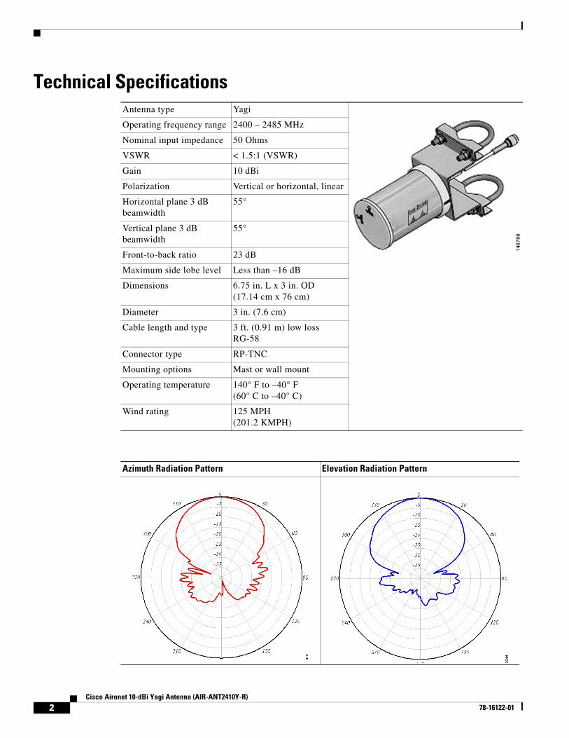
Technical SpecificationsAntenna type Yagi
Operating frequency range 2400 – 2485 MHz
Nominal input impedance 50 Ohms
VSWR < 1.5:1 (VSWR)
Gain 10 dBi
Polarization Vertical or horizontal, linear
Horizontal plane 3 dB beamwidth
55°
Vertical plane 3 dB beamwidth
55°
Front-to-back ratio 23 dB
Maximum side lobe level Less than –16 dB
Dimensions 6.75 in. L x 3 in. OD (17.14 cm x 76 cm)
Diameter 3 in. (7.6 cm)
Cable length and type 3 ft. (0.91 m) low loss RG-58
Connector type RP-TNC
Mounting options Mast or wall mount
Operating temperature 140° F to –40° F(60° C to –40° C)
Wind rating 125 MPH (201.2 KMPH)
Azimuth Radiation Pattern Elevation Radiation Pattern
3Cisco Aironet 10-dBi Yagi Antenna (AIR-ANT2410Y-R)
78-16122-01
System RequirementsThis antenna is designed for use with Cisco Aironet access points and bridges but can be used with any 2.4-GHz Cisco Aironet radio device that uses an RP-TNC connector.
Safety Precautions
Each year hundreds of people are killed or injured when attempting to install an antenna. In many of these cases, the victim was aware of the danger of electrocution, but did not take adequate steps to avoid the hazard.
For your safety, and to help you achieve a good installation, please read and follow these safety precautions. They may save your life!
1. If you are installing an antenna for the first time, for your own safety as well as others, seek professional assistance. Your Cisco sales representative can explain which mounting method to use for the size and type antenna you are about to install.
2. Select your installation site with safety, as well as performance in mind. Remember: electric power lines and phone lines look alike. For your safety, assume that any overhead line can kill you.
3. Call your electric power company. Tell them your plans and ask them to come look at your proposed installation. This is a small inconvenience considering your life is at stake.
4. Plan your installation carefully and completely before you begin. Successful raising of a mast or tower is largely a matter of coordination. Each person should be assigned to a specific task, and should know what to do and when to do it. One person should be in charge of the operation to issue instructions and watch for signs of trouble.
5. When installing your antenna, remember:
a. Do not use a metal ladder.
b. Do not work on a wet or windy day.
c. Do dress properly—shoes with rubber soles and heels, rubber gloves, long sleeved shirt or jacket.
6. If the assembly starts to drop, get away from it and let it fall. Remember, the antenna, mast, cable, and metal guy wires are all excellent conductors of electrical current. Even the slightest touch of any of these parts to a power line complete an electrical path through the antenna and the installer: you!
7. If any part of the antenna system should come in contact with a power line, don’t touch it or try to remove it yourself. Call your local power company. They will remove it safely.
8. If an accident should occur with the power lines call for qualified emergency help immediately.
Warning In order to comply with FCC radio frequency (RF) exposure limits, antennas should be located at a minimum of 7.9 inches (20 cm) or more from the body of all persons. Statement 332
4Cisco Aironet 10-dBi Yagi Antenna (AIR-ANT2410Y-R)
78-16122-01
Installation Notes
General Installation Instructions for Mast-Mounted AntennasThe following instructions are common to most mast-mounted installations.
Step 1 Assemble your new antenna on the ground at the installation site.
Step 2 Attach the antenna to the mast and connect its coaxial cable while you are on the ground.
Step 3 If you lose control of the mast while raising it, make sure that it does not fall in the wrong direction. Use a durable non-conductive rope secured at each 2-foot level as the mast is raised. Have an assistant tend the rope, ready to pull the mast clear of any hazards (such as power lines) if it begins to fall.
Step 4 Use the mounting bracket and hardware provided with the antenna.
Step 5 If the installation will use guy wires:
a. Install guy anchor bolts.
b. Estimate the length of guy wire and cut it before raising the mast.
c. Attach guy wires to a mast using guy rings.
Step 6 Carefully connect the antenna and mast assembly to its mounting bracket and tighten the clamp bolts.
a. For a guyed installation, you must have at least one assistant to hold the mast upright while you attach and tighten the guy wires to the anchor bolts.
Step 7 Attach the provided self-adhering DANGER label at eye level on the mast.
Step 8 Install ground rods to remove any static electricity buildup and connect a ground wire to the mast and ground rod. Use ground rods designed for that purpose, not a spare piece of pipe.
Grounding the AntennaFollow these steps to ground the antenna in accordance with national electrical code instructions.
Step 1 Use No. 10 AWG copper or No. 8 or larger copper-clad steel or bronze wire as ground wires for both mast and lead-in. Securely clamp the wire to the bottom of the mast.
Step 2 Secure the lead-in wire to an antenna discharge unit and the mast ground wire to the building with stand-off insulators spaced from 4 ft (1.2 m) to 8 ft (2.4 m) apart.
Step 3 Mount the antenna discharge unit as closely as possible to where the lead-in wire enters the building.
Step 4 Drill a hole in the building’s wall as closely as possible to the equipment to which you will connect the lead-in cable.
Caution There may be wires in the wall. Make sure your drilling location is clear of any obstructions or other hazards.
Step 5 Pull the cable through the hole and form a drip loop close to where it enters the building.
Step 6 Thoroughly waterproof the lead-in area.
5Cisco Aironet 10-dBi Yagi Antenna (AIR-ANT2410Y-R)
78-16122-01
Step 7 Install a lightning arrestor.
Step 8 Connect the lead-in cable to the equipment.
Choosing a Mounting LocationThe antenna is designed to create a directional broadcast pattern. To achieve this pattern, the antenna should be mounted clear of any obstructions to the sides of the radiating element. If the mounting location is on the side of a building or tower, the antenna pattern is degraded on the building or tower side.
Site Selection
Before attempting to install your antenna, determine where you can best place the antenna for safety and performance.
Follow these steps to determine a safe distance from wires, power lines, and trees.
Step 1 Measure the height of your antenna.
Step 2 Add this length to the length of your tower or mast and then double this total for the minimum recommended safe distance.
Caution If you are unable to maintain this safe distance, stop and get professional help.
Generally, the higher an antenna is above the ground, the better it performs. Good practice is to install your antenna about 5 to 10 ft (1.5 to 3 m) above the roof line and away from all power lines and obstructions. If possible, find a mounting place directly above your wireless device so that the lead-in cable can be as short as possible.
Note The antenna can also be mounted on a wall or other flat vertical surface. Mounting hardware is not provided.
Tools and Equipment RequiredA mast mounting installation kit is shipped with the antenna. To install the antenna on a mast, you need the following tools and equipment.
• A 5/16-in. (8 mm) wrench or suitable adjustable wrench
• A 5/16-in. (8 mm) hex allen wrench (if you need to change the antenna polarity)
• A small standard screw driver (if you need to change the antenna polarity)
• Cable ties and electrical tape
6Cisco Aironet 10-dBi Yagi Antenna (AIR-ANT2410Y-R)
78-16122-01
Note The antenna can also be mounted on a wall or other flat vertical surface. Mounting hardware is not provided.
The following section contains a typical procedure for installing the antenna on a mast. Your installation may vary. Before you begin, you may want to refer to Figure 1.
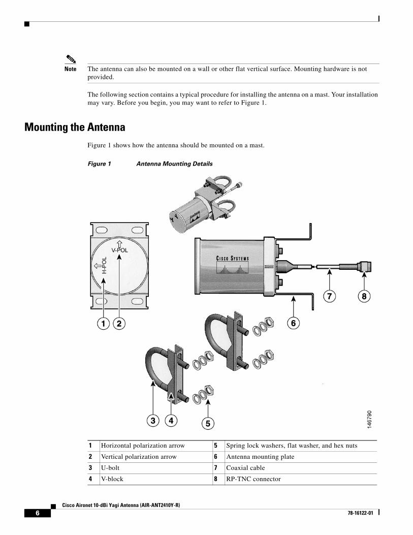
Mounting the AntennaFigure 1 shows how the antenna should be mounted on a mast.
Figure 1 Antenna Mounting Details
1 Horizontal polarization arrow 5 Spring lock washers, flat washer, and hex nuts
2 Vertical polarization arrow 6 Antenna mounting plate
3 U-bolt 7 Coaxial cable
4 V-block 8 RP-TNC connector
7Cisco Aironet 10-dBi Yagi Antenna (AIR-ANT2410Y-R)
78-16122-01
Mounting on a Mast
Follow these instructions to mount the antenna on a mast.
Step 1 Remove the bag of hardware from the shipping carton and verify that it contains the following hardware:
a. Two V blocks
b. Two U bolts
c. Four 5/16-18 hex nuts
d. Four flat washers
e. Four spring lock washers
f. One piece of sealant wrap
Step 2 Place a U bolt around the mast and place a V block on the U bolt.
Step 3 Place the holes in the top flange of the antenna on the U bolt.
a. Make sure the antenna is positioned so that the arrow labelled V-POL is pointing up. The uncovered drain holes will on at the bottom of the antenna radome and the covered drain holes will be on the side.
Note The antenna ships in the vertical polarization mode. but you can mount it in the horizontal polarization mode. See the “Changing the Polarization” section on page 8 for instructions.
Step 4 Place a spring lock washer and flat washer on each end of the U bolt
Step 5 Start a 5/16-18 hex nut on each end of the U bolt and tighten finger tight.
Step 6 Repeat Steps 2 through 5 for the bottom flange of the antenna.
Step 7 Rotate the antenna until it points towards the other WLAN antenna your wireless device is to communicate with.
Note The accuracy of the orientation should be within 15 degrees to achieve maximum gain. This is especially important if the path length is over 1 mile (1.6 kilometers). If you use this antenna to Connect to several terminals, aim it in the general direction of the group. If the paths are not obstructed or are less than 1 mile (1.6 kilometers), this arrangement should work well.
Step 8 Use a 5/16-in (8-mm) wrench or suitable adjustable wrench to tighten the assembly to the mast. Tighten the hex nuts evenly. Do not overtighten.
Step 9 Secure the antenna cable to the mast with cable ties or electrical tape.
Step 10 Remove the paper backing from the sealant tape and wrap the connectors. Start wrapping 1/2-in (13 mm) above the top connector. Stretch the tape tight and continue wrapping to 1/2-in (13 mm) below the bottom connector.
Step 11 Wrap the sealant tape with electrical tape.
8Cisco Aironet 10-dBi Yagi Antenna (AIR-ANT2410Y-R)
78-16122-01
Note The antenna is DC grounded. However, Cisco recommends that you install lightning-protection devices in your system. See the Installation Instructions for Cisco Aironet Lightning Arrestors. This document is available on the World Wide Web at the following URL:
http://www.cisco.com/en/US/docs/wireless/lightning_arrestor/installation/guide/hslar.html
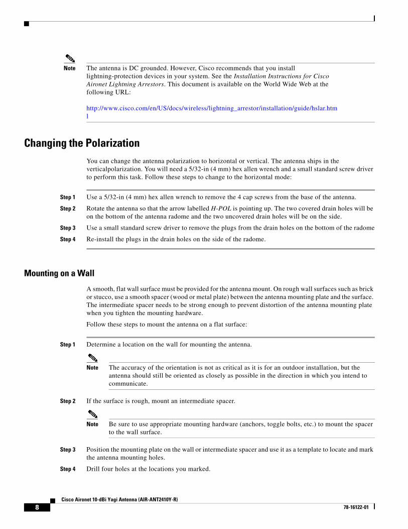
Changing the PolarizationYou can change the antenna polarization to horizontal or vertical. The antenna ships in the verticalpolarization. You will need a 5/32-in (4 mm) hex allen wrench and a small standard screw driver to perform this task. Follow these steps to change to the horizontal mode:
Step 1 Use a 5/32-in (4 mm) hex allen wrench to remove the 4 cap screws from the base of the antenna.
Step 2 Rotate the antenna so that the arrow labelled H-POL is pointing up. The two covered drain holes will be on the bottom of the antenna radome and the two uncovered drain holes will be on the side.
Step 3 Use a small standard screw driver to remove the plugs from the drain holes on the bottom of the radome
Step 4 Re-install the plugs in the drain holes on the side of the radome.
Mounting on a Wall
A smooth, flat wall surface must be provided for the antenna mount. On rough wall surfaces such as brick or stucco, use a smooth spacer (wood or metal plate) between the antenna mounting plate and the surface. The intermediate spacer needs to be strong enough to prevent distortion of the antenna mounting plate when you tighten the mounting hardware.
Follow these steps to mount the antenna on a flat surface:
Step 1 Determine a location on the wall for mounting the antenna.
Note The accuracy of the orientation is not as critical as it is for an outdoor installation, but the antenna should still be oriented as closely as possible in the direction in which you intend to communicate.
Step 2 If the surface is rough, mount an intermediate spacer.
Note Be sure to use appropriate mounting hardware (anchors, toggle bolts, etc.) to mount the spacer to the wall surface.
Step 3 Position the mounting plate on the wall or intermediate spacer and use it as a template to locate and mark the antenna mounting holes.
Step 4 Drill four holes at the locations you marked.
9Cisco Aironet 10-dBi Yagi Antenna (AIR-ANT2410Y-R)
78-16122-01
Step 5 Position the antenna and antenna mounting plate over the holes.
Step 6 Start the fasteners into the holes.
Step 7 Use a suitable wrench to secure the assembly to the surface and tighten the fasteners. Do not overtighten.
Step 8 Apply the danger label to a plainly visible area adjacent to the antenna.
Note The antenna is DC grounded. It is recommended that you install lightning-protection devices in your system. See the Installation Instructions for Cisco Aironet Lightning Arrestors. This document is available on the World Wide Web at the following URL:
http://www.cisco.com/en/US/docs/wireless/lightning_arrestor/installation/guide/hslar.html
Suggested CableCisco recommends a high-quality, low-loss cable for use with the antenna.
Note Coaxial cable loses efficiency as the frequency increases, resulting in signal loss. The cable should be kept as short as possible because cable length also determines the amount of signal loss (the longer the run, the greater the loss).
The antenna terminates with a RP-TNC plug after a short, 3-ft (0.91-m) cable. The mating connector to the antenna is an appropriate RP-TNC jack. The connector on the opposite end will vary according to the type of equipment used.
After the cable is attached to the antenna, make sure that the connections are sealed (if outdoors) to prevent moisture and other weathering elements from affecting performance. Cisco recommends using a coax seal (such as CoaxSeal) for outdoor connections. Silicon sealant or electrical tape are not recommended for sealing outdoor connections.
Translated Safety WarningsThis section provides translations of the safety warnings that appear in this publication. These translated safety warnings apply to other documents in which they appear in English. The following safety warnings appear in this section:
• Statement 332—Antenna Installation Warning
10Cisco Aironet 10-dBi Yagi Antenna (AIR-ANT2410Y-R)
78-16122-01
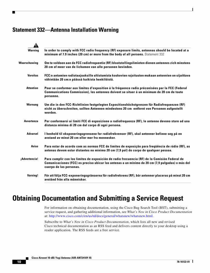
Statement 332—Antenna Installation Warning
Obtaining Documentation and Submitting a Service RequestFor information on obtaining documentation, using the Cisco Bug Search Tool (BST), submitting a service request, and gathering additional information, see What’s New in Cisco Product Documentation at: http://www.cisco.com/c/en/us/td/docs/general/whatsnew/whatsnew.html.
Subscribe to What’s New in Cisco Product Documentation, which lists all new and revised Cisco technical documentation as an RSS feed and delivers content directly to your desktop using a reader application. The RSS feeds are a free service.
Warning In order to comply with FCC radio frequency (RF) exposure limits, antennas should be located at a minimum of 7.9 inches (20 cm) or more from the body of all persons. Statement 332
Waarschuwing Om te voldoen aan de FCC radiofrequentie (RF) blootstellingslimieten dienen antennes zich minstens 20 cm of meer van de lichamen van alle personen bevinden.
Varoitus FCC:n antamien radiotaajuuksille altistumista koskevien rajoitusten mukaan antennien on sijaittava vähintään 20 cm:n päässä kaikista henkilöistä.
Attention Pour se conformer aux limites d'exposition à la fréquence radio préconisées par la FCC (Federal Communications Commission), les antennes doivent se situer à un minimum de 20 cm de toute personne.
Warnung Um die in den FCC-Richtlinien festgelegten Expositionshöchstgrenzen für Radiofrequenzen (RF) nicht zu überschreiten, sollten Antennen mindestens 20 cm entfernt von Personen aufgestellt werden.
Avvertenza Per conformarsi ai limiti FCC di esposizione a radiofrequenza (RF), le antenne devono stare ad una distanza minima di 20 cm dal corpo di ogni persona.
Advarsel I henhold til eksponeringsgrensene for radiofrekvenser (RF), skal antenner befinne seg på en avstand av minst 20 cm eller mer fra mennesker.
Aviso Para estar de acordo com as normas FCC de limites de exposição para freqüência de rádio (RF), as antenas devem estar distantes no mínimo 20 cm (7,9 pol) do corpo de qualquer pessoa.
¡Advertencia! Para cumplir con los límites de exposición de radio frecuencia (RF) de la Comisión Federal de Comunicaciones (FCC) es preciso ubicar las antenas a un mínimo de 20 cm (7,9 pulgadas) o más del cuerpo de las personas.
Varning! För att följa FCC-exponeringsgränserna för radiofrekvens (RF), bör antenner placeras på minst 20 cm avstånd från alla människor.
11Cisco Aironet 10-dBi Yagi Antenna (AIR-ANT2410Y-R)
78-16122-01
Cisco and the Cisco logo are trademarks or registered trademarks of Cisco and/or its affiliates in the U.S. and other countries. To view a list of Cisco trademarks, go to this URL: www.cisco.com/go/trademarks. Third-party trademarks mentioned are the property of their respective owners. The use of the word partner does not imply a partnership relationship between Cisco and any other company. (1110R)
Any Internet Protocol (IP) addresses and phone numbers used in this document are not intended to be actual addresses and phone numbers. Any examples, command display output, network topology diagrams, and other figures included in the document are shown for illustrative purposes only. Any use of actual IP addresses or phone numbers in illustrative content is unintentional and coincidental.
© 2007 Cisco Systems, Inc. All rights reserved.
12Cisco Aironet 10-dBi Yagi Antenna (AIR-ANT2410Y-R)
78-16122-01