Cisco 1800 Series Integrated Services Routers … · Installing WICs, VWICs, and HWICs 9-1 CHAPTER...
100
Americas Headquarters Cisco Systems, Inc. 170 West Tasman Drive San Jose, CA 95134-1706 USA http://www.cisco.com Tel: 408 526-4000 800 553-NETS (6387) Fax: 408 527-0883 Cisco 1800 Series Integrated Services Routers (Modular) Hardware Installation Guide Text Part Number: OL-5876-03
Transcript of Cisco 1800 Series Integrated Services Routers … · Installing WICs, VWICs, and HWICs 9-1 CHAPTER...

Cisco 1800 Series Integrated Services Routers (Modular) Hardware Installation Guide
Americas HeadquartersCisco Systems, Inc.170 West Tasman DriveSan Jose, CA 95134-1706 USAhttp://www.cisco.comTel: 408 526-4000
800 553-NETS (6387)Fax: 408 527-0883
Text Part Number: OL-5876-03

THE SPECIFICATIONS AND INFORMATION REGARDING THE PRODUCTS IN THIS MANUAL ARE SUBJECT TO CHANGE WITHOUT NOTICE. ALL STATEMENTS, INFORMATION, AND RECOMMENDATIONS IN THIS MANUAL ARE BELIEVED TO BE ACCURATE BUT ARE PRESENTED WITHOUT WARRANTY OF ANY KIND, EXPRESS OR IMPLIED. USERS MUST TAKE FULL RESPONSIBILITY FOR THEIR APPLICATION OF ANY PRODUCTS.
THE SOFTWARE LICENSE AND LIMITED WARRANTY FOR THE ACCOMPANYING PRODUCT ARE SET FORTH IN THE INFORMATION PACKET THAT SHIPPED WITH THE PRODUCT AND ARE INCORPORATED HEREIN BY THIS REFERENCE. IF YOU ARE UNABLE TO LOCATE THE SOFTWARE LICENSE OR LIMITED WARRANTY, CONTACT YOUR CISCO REPRESENTATIVE FOR A COPY.
The following information is for FCC compliance of Class A devices: This equipment has been tested and found to comply with the limits for a Class A digital device, pursuant to part 15 of the FCC rules. These limits are designed to provide reasonable protection against harmful interference when the equipment is operated in a commercial environment. This equipment generates, uses, and can radiate radio-frequency energy and, if not installed and used in accordance with the instruction manual, may cause harmful interference to radio communications. Operation of this equipment in a residential area is likely to cause harmful interference, in which case users will be required to correct the interference at their own expense.
The following information is for FCC compliance of Class B devices: The equipment described in this manual generates and may radiate radio-frequency energy. If it is not installed in accordance with Cisco’s installation instructions, it may cause interference with radio and television reception. This equipment has been tested and found to comply with the limits for a Class B digital device in accordance with the specifications in part 15 of the FCC rules. These specifications are designed to provide reasonable protection against such interference in a residential installation. However, there is no guarantee that interference will not occur in a particular installation.
Modifying the equipment without Cisco’s written authorization may result in the equipment no longer complying with FCC requirements for Class A or Class B digital devices. In that event, your right to use the equipment may be limited by FCC regulations, and you may be required to correct any interference to radio or television communications at your own expense.
You can determine whether your equipment is causing interference by turning it off. If the interference stops, it was probably caused by the Cisco equipment or one of its peripheral devices. If the equipment causes interference to radio or television reception, try to correct the interference by using one or more of the following measures:
• Turn the television or radio antenna until the interference stops.
• Move the equipment to one side or the other of the television or radio.
• Move the equipment farther away from the television or radio.
• Plug the equipment into an outlet that is on a different circuit from the television or radio. (That is, make certain the equipment and the television or radio are on circuits controlled by different circuit breakers or fuses.)
Modifications to this product not authorized by Cisco Systems, Inc. could void the FCC approval and negate your authority to operate the product.
The Cisco implementation of TCP header compression is an adaptation of a program developed by the University of California, Berkeley (UCB) as part of UCB’s public domain version of the UNIX operating system. All rights reserved. Copyright © 1981, Regents of the University of California.
NOTWITHSTANDING ANY OTHER WARRANTY HEREIN, ALL DOCUMENT FILES AND SOFTWARE OF THESE SUPPLIERS ARE PROVIDED “AS IS” WITH ALL FAULTS. CISCO AND THE ABOVE-NAMED SUPPLIERS DISCLAIM ALL WARRANTIES, EXPRESSED OR IMPLIED, INCLUDING, WITHOUT LIMITATION, THOSE OF MERCHANTABILITY, FITNESS FOR A PARTICULAR PURPOSE AND NONINFRINGEMENT OR ARISING FROM A COURSE OF DEALING, USAGE, OR TRADE PRACTICE.
IN NO EVENT SHALL CISCO OR ITS SUPPLIERS BE LIABLE FOR ANY INDIRECT, SPECIAL, CONSEQUENTIAL, OR INCIDENTAL DAMAGES, INCLUDING, WITHOUT LIMITATION, LOST PROFITS OR LOSS OR DAMAGE TO DATA ARISING OUT OF THE USE OR INABILITY TO USE THIS MANUAL, EVEN IF CISCO OR ITS SUPPLIERS HAVE BEEN ADVISED OF THE POSSIBILITY OF SUCH DAMAGES.
Cisco and the Cisco Logo are trademarks of Cisco Systems, Inc. and/or its affiliates in the U.S. and other countries. A listing of Cisco's trademarks can be found at www.cisco.com/go/trademarks. Third party trademarks mentioned are the property of their respective owners. The use of the word partner does not imply a partnership relationship between Cisco and any other company. (1005R)
Cisco 1800 Series Integrated Services Routers (Fixed) Hardware Installation Guide Copyright ©2005-2008 Cisco Systems, Inc. All rights reserved.
Contents
C H A P T E R 1 Introduction to Cisco 1800 Series Routers (Modular) Hardware Documentation 1-5
Objectives 1-5
Audience 1-6
Organization 1-6
Conventions 1-7
Safety Warnings 1-7
Related Documentation 1-13
Cisco One-Year Limited Hardware Warranty Terms 1-14
Searching for Cisco Documents 1-15
Obtaining Documentation and Submitting a Service Request 1-15
C H A P T E R 2 Overview of Cisco 1800 Series Routers (Modular) 2-1
Hardware Features 2-2
Product Serial Number Location 2-3
Cisco Product Identification Tool 2-3
Interfaces 2-3
Interfaces on the Cisco 1841 Router 2-4
Interfaces on the Cisco 1861 Integrated Services Router 2-4
Removable and Interchangeable Modules 2-5
Memory 2-5
LED Indicators 2-6
Chassis Ventilation 2-7
Real-Time Clock 2-7
Chassis Security 2-8
Chassis Views 2-8
Interface Numbering 2-9
Interface Numbering on the 1861 Integrated Services Router 2-10
Specifications 2-11
Regulatory Compliance 2-11
C H A P T E R 3 Preinstallation Requirements and Planning for Cisco 1800 Series Routers (Modular) 3-1
Safety Recommendations 3-1
Safety with Electricity 3-2
Preventing Electrostatic Discharge Damage 3-3
General Site Requirements 3-3
Power Supply Considerations 3-3
Site Environment 3-4
1Cisco 1800 Series Routers (Modular) Hardware Installation Guide
OL-5876-03
Contents
Site Configuration 3-4
Installation Checklist 3-4
Site Log 3-5
Inspecting the Router 3-6
Items in the Box for the Cisco 1841 Router 3-6
Items in the Box for the Cisco 1861 Integrated Services Router 3-6
Items not Included in the Box for the Cisco 1861 Integrated Services Router 3-7
Required Tools and Equipment for Installation and Maintenance 3-7
C H A P T E R 4 Chassis Installation Procedures for Cisco 1800 Series Routers (Modular) 4-1
Setting Up the Chassis 4-3
Setting the Chassis on a Desktop 4-3
Rack-Mounting a Cisco 1800 Series Modular-Configuration Router 4-3
Attaching Rack-Mount Brackets 4-4
Installing the Router in a Rack 4-5
Chassis Grounding 4-6
Wall-Mounting the Chassis 4-6
Wall-Mounting the Cisco 1841 Router 4-6
Wall-Mounting the Cisco 1861 Integrated Services Router 4-8
Rack-Mounting the Cisco 1861 Integrated Services Router 4-9
Installing the Chassis Ground Connection 4-11
Installing the Chassis Ground Connection on the Cisco 1841 Router 4-11
Installing the Chassis Ground Connection on the Cisco 1861 Integrated Services Router 4-12
C H A P T E R 5 Cable Information and Specifications for Cisco 1800 Series Routers (Modular) 5-1
Console and Auxiliary Port Considerations 5-1
Console Port Connections 5-1
Auxiliary Port Connections 5-2
Preparing to Connect to a Network 5-2
Ethernet Connections 5-2
Serial Connections 5-3
Configuring Serial Connections 5-3
Serial DTE or DCE Devices 5-3
Signaling Standards Supported 5-3
Distance Limitations 5-4
Asynchronous/Synchronous Serial Module Baud Rates 5-4
ISDN BRI Connections 5-5
CSU/DSU Connections 5-5
2Cisco 1800 Series Routers (Modular) Hardware Installation Guide
OL-5876-03
Contents
C H A P T E R 6 Cable Connection Procedures for Cisco 1800 Series Routers (Modular) 6-1
Power Connections 6-1
Connecting WAN and LAN Cables 6-2
Ports and Cabling 6-2
Connection Procedures and Precautions 6-3
Connecting to a Console Terminal or Modem 6-3
Connecting to the Console Port 6-4
Connecting to the Auxiliary Port 6-4
Connecting Power to the Cisco 1861 Integrated Services Router 6-5
C H A P T E R 7 Power-Up Procedures for Cisco 1800 Series Routers (Modular) 7-1
Powering Up Cisco 1800 Series Routers 7-1
Checklist for Power Up 7-2
LED Indicators 7-2
Power-Up Procedure 7-2
Verifying the LED Indicators on the 1841 Router 7-4
Verifying the LED Indicators on the 1861 Integrated Services Router 7-4
Verifying the Hardware Configuration 7-5
Initial Configuration of the Router 7-5
Initial Configuration 7-5
Cisco Router and Security Device Manager 7-6
Verifying the Initial Configuration 7-6
Completing the Configuration 7-6
Powering up the Cisco 1861 Integrated Services Router 7-7
Software Components of the Cisco 1861 Integrated Services Router 7-7
C H A P T E R 8 Troubleshooting Cisco 1800 Series Routers (Modular) 8-1
Problem Solving 8-1
Troubleshooting the Power and Cooling Systems 8-2
Normal Indications 8-2
Fault Indications 8-2
Environmental Reporting Features 8-3
Troubleshooting Cables, Connections, and Interface Cards 8-3
Reading LEDs 8-4
System Messages 8-5
Recovering a Lost Password 8-6
More Troubleshooting Help 8-6
3Cisco 1800 Series Routers (Modular) Hardware Installation Guide
OL-5876-03
Contents
C H A P T E R 9 Installing Interface Cards in Cisco 1800 Series Routers (Modular) 9-1
Cisco Interface Cards Installation Guide 9-1
Related Product Documentation 9-1
Installing WICs, VWICs, and HWICs 9-1
C H A P T E R 10 Installing and Replacing CompactFlash Memory Cards on Cisco 1800 Series Routers (Modular) 10-1
Preventing Electrostatic Discharge Damage 10-1
Replacing CompactFlash Memory Cards 10-1
Removing a CompactFlash Memory Card 10-2
Installing a CompactFlash Memory Card 10-2
Using the Compact Flash Guard 10-2
C H A P T E R 11 Installing and Upgrading Internal Modules in Cisco 1800 Series Routers (Modular) 11-1
Safety Warnings 11-1
Modules Internal to the Cisco 1841 Router 11-2
Opening the Chassis 11-2
Locating Modules 11-4
Installing a SODIMM 11-5
Installing an AIM 11-6
Accessory Kit to Use 11-7
Installation Procedure 11-7
Applying the AIM Label 11-11
Closing the Chassis 11-11
4Cisco 1800 Series Routers (Modular) Hardware Installation Guide
OL-5876-03
Cisco 1800 SeOL-5876-03
C H A P T E R 1
Introduction to Cisco 1800 Series Routers (Modular) Hardware DocumentationThis introduction discusses the objectives, audience, organization, and conventions of the hardware documents for the Cisco 1800 series integrated services routers (modular), and describes related documents that have additional information. It contains the following sections:
• Objectives, page 1-5
• Audience, page 1-6
• Organization, page 1-6
• Conventions, page 1-7
• Safety Warnings, page 1-7
• Related Documentation, page 1-13
• Cisco One-Year Limited Hardware Warranty Terms, page 1-14
• Searching for Cisco Documents, page 1-15
• Obtaining Documentation and Submitting a Service Request, page 1-15
ObjectivesThis documentation explains how to install, maintain, and troubleshoot your router hardware.
Although this documentation provides minimum software configuration information, it is not comprehensive. For detailed software configuration information, see Cisco 1800 series software configuration documentation and the Cisco IOS configuration guide and command reference publications. These publications are available online. See the “Obtaining Documentation and Submitting a Service Request” section on page 1-15 for more information.
This documentation describes the Cisco 1800 series (modular), currently consisting of the Cisco 1841 router and the Cisco 1861 integrated services router (ISR).
Note With the exception of when the Cisco 1861 ISR is specifically mentioned, all information in this document describes the Cisco 1841 router.
To access the warranty, service, and support information, see the “Cisco One-Year Limited Hardware Warranty Terms” section on page 1-14.
1-5ries Routers (Modular) Hardware Installation Guide
Chapter 1 Introduction to Cisco 1800 Series Routers (Modular) Hardware Documentation Audience
AudienceThis documentation is designed for the person installing, configuring, and maintaining the router, who should be familiar with electronic circuitry and wiring practices and has experience as an electronic or electromechanical technician. The documentation identifies those procedures that should be performed only by trained and qualified personnel.
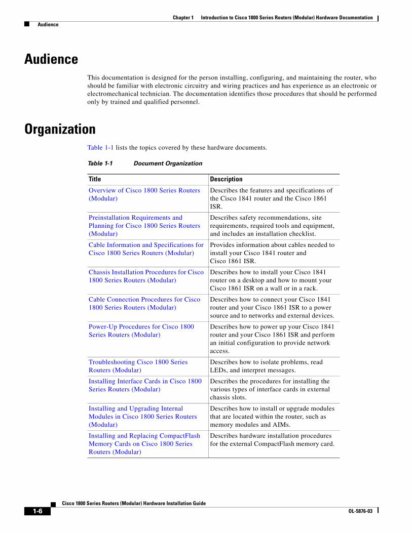
OrganizationTable 1-1 lists the topics covered by these hardware documents.
Table 1-1 Document Organization
Title Description
Overview of Cisco 1800 Series Routers (Modular)
Describes the features and specifications of the Cisco 1841 router and the Cisco 1861 ISR.
Preinstallation Requirements and Planning for Cisco 1800 Series Routers (Modular)
Describes safety recommendations, site requirements, required tools and equipment, and includes an installation checklist.
Cable Information and Specifications for Cisco 1800 Series Routers (Modular)
Provides information about cables needed to install your Cisco 1841 router and Cisco 1861 ISR.
Chassis Installation Procedures for Cisco 1800 Series Routers (Modular)
Describes how to install your Cisco 1841 router on a desktop and how to mount your Cisco 1861 ISR on a wall or in a rack.
Cable Connection Procedures for Cisco 1800 Series Routers (Modular)
Describes how to connect your Cisco 1841 router and your Cisco 1861 ISR to a power source and to networks and external devices.
Power-Up Procedures for Cisco 1800 Series Routers (Modular)
Describes how to power up your Cisco 1841 router and your Cisco 1861 ISR and perform an initial configuration to provide network access.
Troubleshooting Cisco 1800 Series Routers (Modular)
Describes how to isolate problems, read LEDs, and interpret messages.
Installing Interface Cards in Cisco 1800 Series Routers (Modular)
Describes the procedures for installing the various types of interface cards in external chassis slots.
Installing and Upgrading Internal Modules in Cisco 1800 Series Routers (Modular)
Describes how to install or upgrade modules that are located within the router, such as memory modules and AIMs.
Installing and Replacing CompactFlash Memory Cards on Cisco 1800 Series Routers (Modular)
Describes hardware installation procedures for the external CompactFlash memory card.
1-6Cisco 1800 Series Routers (Modular) Hardware Installation Guide
OL-5876-03
Chapter 1 Introduction to Cisco 1800 Series Routers (Modular) Hardware Documentation Conventions
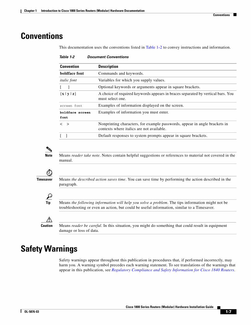
ConventionsThis documentation uses the conventions listed in Table 1-2 to convey instructions and information.
Note Means reader take note. Notes contain helpful suggestions or references to material not covered in the manual.
Timesaver Means the described action saves time. You can save time by performing the action described in the paragraph.
Tip Means the following information will help you solve a problem. The tips information might not be troubleshooting or even an action, but could be useful information, similar to a Timesaver.
Caution Means reader be careful. In this situation, you might do something that could result in equipment damage or loss of data.
Safety WarningsSafety warnings appear throughout this publication in procedures that, if performed incorrectly, may harm you. A warning symbol precedes each warning statement. To see translations of the warnings that appear in this publication, see Regulatory Compliance and Safety Information for Cisco 1840 Routers.
Table 1-2 Document Conventions
Convention Description
boldface font Commands and keywords.
italic font Variables for which you supply values.
[ ] Optional keywords or arguments appear in square brackets.
{x | y | z} A choice of required keywords appears in braces separated by vertical bars. You must select one.
screen font Examples of information displayed on the screen.
boldface screen font
Examples of information you must enter.
< > Nonprinting characters, for example passwords, appear in angle brackets in contexts where italics are not available.
[ ] Default responses to system prompts appear in square brackets.
1-7Cisco 1800 Series Routers (Modular) Hardware Installation Guide
OL-5876-03
Chapter 1 Introduction to Cisco 1800 Series Routers (Modular) Hardware Documentation Safety Warnings
Note The title Regulatory Compliance and Safety Information for Cisco 1840 Routers refers to a specific chassis model: the Cisco 1840. The Cisco 1841 router received compliance certification under the chassis model Cisco 1840. The same regulatory compliance and safety information for the Cisco 1841 router is applicable to the Cisco 1861 ISR.
Warning IMPORTANT SAFETY INSTRUCTIONS
This warning symbol means danger. You are in a situation that could cause bodily injury. Before you work on any equipment, be aware of the hazards involved with electrical circuitry and be familiar with standard practices for preventing accidents. Use the statement number provided at the end of each warning to locate its translation in the translated safety warnings that accompanied this device. Statement 1071
SAVE THESE INSTRUCTIONS
Waarschuwing BELANGRIJKE VEILIGHEIDSINSTRUCTIES
Dit waarschuwingssymbool betekent gevaar. U verkeert in een situatie die lichamelijk letsel kan veroorzaken. Voordat u aan enige apparatuur gaat werken, dient u zich bewust te zijn van de bij elektrische schakelingen betrokken risico's en dient u op de hoogte te zijn van de standaard praktijken om ongelukken te voorkomen. Gebruik het nummer van de verklaring onderaan de waarschuwing als u een vertaling van de waarschuwing die bij het apparaat wordt geleverd, wilt raadplegen.
BEWAAR DEZE INSTRUCTIES
Varoitus TÄRKEITÄ TURVALLISUUSOHJEITA
Tämä varoitusmerkki merkitsee vaaraa. Tilanne voi aiheuttaa ruumiillisia vammoja. Ennen kuin käsittelet laitteistoa, huomioi sähköpiirien käsittelemiseen liittyvät riskit ja tutustu onnettomuuksien yleisiin ehkäisytapoihin. Turvallisuusvaroitusten käännökset löytyvät laitteen mukana toimitettujen käännettyjen turvallisuusvaroitusten joukosta varoitusten lopussa näkyvien lausuntonumeroiden avulla.
SÄILYTÄ NÄMÄ OHJEET
Attention IMPORTANTES INFORMATIONS DE SÉCURITÉ
Ce symbole d'avertissement indique un danger. Vous vous trouvez dans une situation pouvant entraîner des blessures ou des dommages corporels. Avant de travailler sur un équipement, soyez conscient des dangers liés aux circuits électriques et familiarisez-vous avec les procédures couramment utilisées pour éviter les accidents. Pour prendre connaissance des traductions des avertissements figurant dans les consignes de sécurité traduites qui accompagnent cet appareil, référez-vous au numéro de l'instruction situé à la fin de chaque avertissement.
CONSERVEZ CES INFORMATIONS
1-8Cisco 1800 Series Routers (Modular) Hardware Installation Guide
OL-5876-03
Chapter 1 Introduction to Cisco 1800 Series Routers (Modular) Hardware Documentation Safety Warnings
Warnung WICHTIGE SICHERHEITSHINWEISE
Dieses Warnsymbol bedeutet Gefahr. Sie befinden sich in einer Situation, die zu Verletzungen führen kann. Machen Sie sich vor der Arbeit mit Geräten mit den Gefahren elektrischer Schaltungen und den üblichen Verfahren zur Vorbeugung vor Unfällen vertraut. Suchen Sie mit der am Ende jeder Warnung angegebenen Anweisungsnummer nach der jeweiligen Übersetzung in den übersetzten Sicherheitshinweisen, die zusammen mit diesem Gerät ausgeliefert wurden.
BEWAHREN SIE DIESE HINWEISE GUT AUF.
Avvertenza IMPORTANTI ISTRUZIONI SULLA SICUREZZA
Questo simbolo di avvertenza indica un pericolo. La situazione potrebbe causare infortuni alle persone. Prima di intervenire su qualsiasi apparecchiatura, occorre essere al corrente dei pericoli relativi ai circuiti elettrici e conoscere le procedure standard per la prevenzione di incidenti. Utilizzare il numero di istruzione presente alla fine di ciascuna avvertenza per individuare le traduzioni delle avvertenze riportate in questo documento.
CONSERVARE QUESTE ISTRUZIONI
Advarsel VIKTIGE SIKKERHETSINSTRUKSJONER
Dette advarselssymbolet betyr fare. Du er i en situasjon som kan føre til skade på person. Før du begynner å arbeide med noe av utstyret, må du være oppmerksom på farene forbundet med elektriske kretser, og kjenne til standardprosedyrer for å forhindre ulykker. Bruk nummeret i slutten av hver advarsel for å finne oversettelsen i de oversatte sikkerhetsadvarslene som fulgte med denne enheten.
TA VARE PÅ DISSE INSTRUKSJONENE
Aviso INSTRUÇÕES IMPORTANTES DE SEGURANÇA
Este símbolo de aviso significa perigo. Você está em uma situação que poderá ser causadora de lesões corporais. Antes de iniciar a utilização de qualquer equipamento, tenha conhecimento dos perigos envolvidos no manuseio de circuitos elétricos e familiarize-se com as práticas habituais de prevenção de acidentes. Utilize o número da instrução fornecido ao final de cada aviso para localizar sua tradução nos avisos de segurança traduzidos que acompanham este dispositivo.
GUARDE ESTAS INSTRUÇÕES
¡Advertencia! INSTRUCCIONES IMPORTANTES DE SEGURIDAD
Este símbolo de aviso indica peligro. Existe riesgo para su integridad física. Antes de manipular cualquier equipo, considere los riesgos de la corriente eléctrica y familiarícese con los procedimientos estándar de prevención de accidentes. Al final de cada advertencia encontrará el número que le ayudará a encontrar el texto traducido en el apartado de traducciones que acompaña a este dispositivo.
GUARDE ESTAS INSTRUCCIONES
1-9Cisco 1800 Series Routers (Modular) Hardware Installation Guide
OL-5876-03
Chapter 1 Introduction to Cisco 1800 Series Routers (Modular) Hardware Documentation Safety Warnings
Varning! VIKTIGA SÄKERHETSANVISNINGAR
Denna varningssignal signalerar fara. Du befinner dig i en situation som kan leda till personskada. Innan du utför arbete på någon utrustning måste du vara medveten om farorna med elkretsar och känna till vanliga förfaranden för att förebygga olyckor. Använd det nummer som finns i slutet av varje varning för att hitta dess översättning i de översatta säkerhetsvarningar som medföljer denna anordning.
SPARA DESSA ANVISNINGAR
1-10Cisco 1800 Series Routers (Modular) Hardware Installation Guide
OL-5876-03
Chapter 1 Introduction to Cisco 1800 Series Routers (Modular) Hardware Documentation Safety Warnings
Aviso INSTRUÇÕES IMPORTANTES DE SEGURANÇA
Este símbolo de aviso significa perigo. Você se encontra em uma situação em que há risco de lesões corporais. Antes de trabalhar com qualquer equipamento, esteja ciente dos riscos que envolvem os circuitos elétricos e familiarize-se com as práticas padrão de prevenção de acidentes. Use o número da declaração fornecido ao final de cada aviso para localizar sua tradução nos avisos de segurança traduzidos que acompanham o dispositivo.
GUARDE ESTAS INSTRUÇÕES
Advarsel VIGTIGE SIKKERHEDSANVISNINGER
Dette advarselssymbol betyder fare. Du befinder dig i en situation med risiko for legemesbeskadigelse. Før du begynder arbejde på udstyr, skal du være opmærksom på de involverede risici, der er ved elektriske kredsløb, og du skal sætte dig ind i standardprocedurer til undgåelse af ulykker. Brug erklæringsnummeret efter hver advarsel for at finde oversættelsen i de oversatte advarsler, der fulgte med denne enhed.
GEM DISSE ANVISNINGER
1-11Cisco 1800 Series Routers (Modular) Hardware Installation Guide
OL-5876-03
Chapter 1 Introduction to Cisco 1800 Series Routers (Modular) Hardware Documentation Safety Warnings
1-12Cisco 1800 Series Routers (Modular) Hardware Installation Guide
OL-5876-03
Chapter 1 Introduction to Cisco 1800 Series Routers (Modular) Hardware Documentation Related Documentation
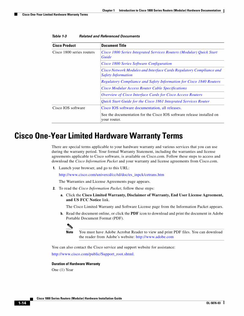
Related DocumentationThe Cisco IOS software that runs your Cisco 1800 series router includes extensive features and functionality. For information that is beyond the scope of this document, or for additional information, see Table 1-3.
Timesaver Make sure that you have access to the documents listed in Table 1-3. Some of these documents are available in print, and all are available on Cisco.com. To order printed documents, see the “Obtaining Documentation and Submitting a Service Request” section on page 1-15.
1-13Cisco 1800 Series Routers (Modular) Hardware Installation Guide
OL-5876-03
Chapter 1 Introduction to Cisco 1800 Series Routers (Modular) Hardware Documentation Cisco One-Year Limited Hardware Warranty Terms
Cisco One-Year Limited Hardware Warranty TermsThere are special terms applicable to your hardware warranty and various services that you can use during the warranty period. Your formal Warranty Statement, including the warranties and license agreements applicable to Cisco software, is available on Cisco.com. Follow these steps to access and download the Cisco Information Packet and your warranty and license agreements from Cisco.com.
1. Launch your browser, and go to this URL:
http://www.cisco.com/univercd/cc/td/doc/es_inpck/cetrans.htm
The Warranties and License Agreements page appears.
2. To read the Cisco Information Packet, follow these steps:
a. Click the Cisco Limited Warranty, Disclaimer of Warranty, End User License Agreement, and US FCC Notice link.
The Cisco Limited Warranty and Software License page from the Information Packet appears.
b. Read the document online, or click the PDF icon to download and print the document in Adobe Portable Document Format (PDF).
Note You must have Adobe Acrobat Reader to view and print PDF files. You can download the reader from Adobe’s website: http://www.adobe.com
You can also contact the Cisco service and support website for assistance:
http://www.cisco.com/public/Support_root.shtml.
Duration of Hardware Warranty
One (1) Year
Table 1-3 Related and Referenced Documents
Cisco Product Document Title
Cisco 1800 series routers Cisco 1800 Series Integrated Services Routers (Modular) Quick Start Guide
Cisco 1800 Series Software Configuration
Cisco Network Modules and Interface Cards Regulatory Compliance and Safety Information
Regulatory Compliance and Safety Information for Cisco 1840 Routers
Cisco Modular Access Router Cable Specifications
Overview of Cisco Interface Cards for Cisco Access Routers
Quick Start Guide for the Cisco 1861 Integrated Services Router
Cisco IOS software Cisco IOS software documentation, all releases.
See the documentation for the Cisco IOS software release installed on your router.
1-14Cisco 1800 Series Routers (Modular) Hardware Installation Guide
OL-5876-03
Chapter 1 Introduction to Cisco 1800 Series Routers (Modular) Hardware Documentation Searching for Cisco Documents
Replacement, Repair, or Refund Policy for Hardware
Cisco or its service center will use commercially reasonable efforts to ship a replacement part within ten (10) working days after receipt of a Return Materials Authorization (RMA) request. Actual delivery times can vary, depending on the customer location.
Cisco reserves the right to refund the purchase price as its exclusive warranty remedy.
To Receive a Return Materials Authorization (RMA) Number
Contact the company from whom you purchased the product. If you purchased the product directly from Cisco, contact your Cisco Sales and Service Representative.
Complete the following information, and keep it for reference.
Searching for Cisco DocumentsTo search an HTML document using a web browser, press Ctrl-F (Windows) or Cmd-F (Apple). In most browsers, the option to search whole words only, invoke case sensitivity, or search forward and backward is also available.
To search a PDF document in Adobe Reader, use the basic Find toolbar (Ctrl-F) or the Full Reader Search window (Shift-Ctrl-F). Use the Find toolbar to find words or phrases within a specific document. Use the Full Reader Search window to search multiple PDF files simultaneously and to change case sensitivity and other options. Adobe Reader online help has more information about how to search PDF documents.
Obtaining Documentation and Submitting a Service RequestFor information on obtaining documentation, submitting a service request, and gathering additional information, see the monthly What’s New in Cisco Product Documentation, which also lists all new and revised Cisco technical documentation, at:
http://www.cisco.com/en/US/docs/general/whatsnew/whatsnew.html
Subscribe to the What’s New in Cisco Product Documentation as a Really Simple Syndication (RSS) feed and set content to be delivered directly to your desktop using a reader application. The RSS feeds are a free service and Cisco currently supports RSS Version 2.0.
Company product purchased from
Company telephone number
Product model number
Product serial number
Maintenance contract number
1-15Cisco 1800 Series Routers (Modular) Hardware Installation Guide
OL-5876-03

Chapter 1 Introduction to Cisco 1800 Series Routers (Modular) Hardware Documentation Obtaining Documentation and Submitting a Service Request
1-16Cisco 1800 Series Routers (Modular) Hardware Installation Guide
OL-5876-03
Cisco 1800 SeOL-5876-03
C H A P T E R 2
Overview of Cisco 1800 Series Routers (Modular)Cisco 1800 series integrated services routers (ISR) (modular) are modular routers with LAN and WAN connections that can be configured by means of interchangeable interface cards and advanced integration modules (AIMs). The modular design of the routers provides flexibility, allowing you to configure or reconfigure your router according to your needs.
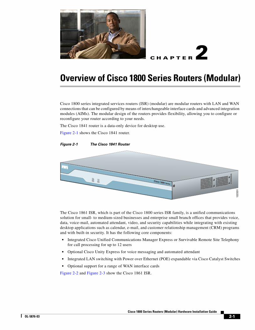
The Cisco 1841 router is a data-only device for desktop use.
Figure 2-1 shows the Cisco 1841 router.
Figure 2-1 The Cisco 1841 Router
The Cisco 1861 ISR, which is part of the Cisco 1800 series ISR family, is a unified communications solution for small- to medium-sized businesses and enterprise small branch offices that provides voice, data, voice-mail, automated attendant, video, and security capabilities while integrating with existing desktop applications such as calendar, e-mail, and customer relationship management (CRM) programs and with built-in security. It has the following core components:
• Integrated Cisco Unified Communications Manager Express or Survivable Remote Site Telephony for call processing for up to 12 users
• Optional Cisco Unity Express for voice messaging and automated attendant
• Integrated LAN switching with Power over Ethernet (POE) expandable via Cisco Catalyst Switches
• Optional support for a range of WAN interface cards
Figure 2-2 and Figure 2-3 show the Cisco 1861 ISR.
SYS PWR
1223
31
SYS ACT Cisco 1800 Series
2-1ries Routers (Modular) Hardware Installation Guide
Chapter 2 Overview of Cisco 1800 Series Routers (Modular) Hardware Features
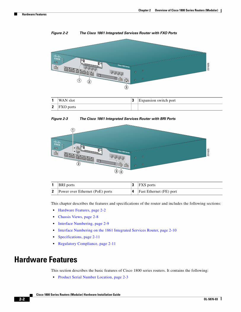
Figure 2-2 The Cisco 1861 Integrated Services Router with FXO Ports
Figure 2-3 The Cisco 1861 Integrated Services Router with BRI Ports
This chapter describes the features and specifications of the router and includes the following sections:
• Hardware Features, page 2-2
• Chassis Views, page 2-8
• Interface Numbering, page 2-9
• Interface Numbering on the 1861 Integrated Services Router, page 2-10
• Specifications, page 2-11
• Regulatory Compliance, page 2-11
Hardware FeaturesThis section describes the basic features of Cisco 1800 series routers. It contains the following:
• Product Serial Number Location, page 2-3
1 WAN slot 3 Expansion switch port
2 FXO ports
2316
26Cisco 1800 Series
SYS
POE
VM
2
3
1
1 BRI ports 3 FXS ports
2 Power over Ethernet (PoE) ports 4 Fast Ethernet (FE) port
2316
25
00
1
Cisco 1800 Series
SYS
POE
VM
3 4
2
1
2-2Cisco 1800 Series Routers (Modular) Hardware Installation Guide
OL-5876-03
Chapter 2 Overview of Cisco 1800 Series Routers (Modular) Hardware Features
• Interfaces, page 2-3
• Removable and Interchangeable Modules, page 2-5
• Memory, page 2-5
• LED Indicators, page 2-6
• Chassis Ventilation, page 2-7
• Real-Time Clock, page 2-7
• Chassis Security, page 2-8
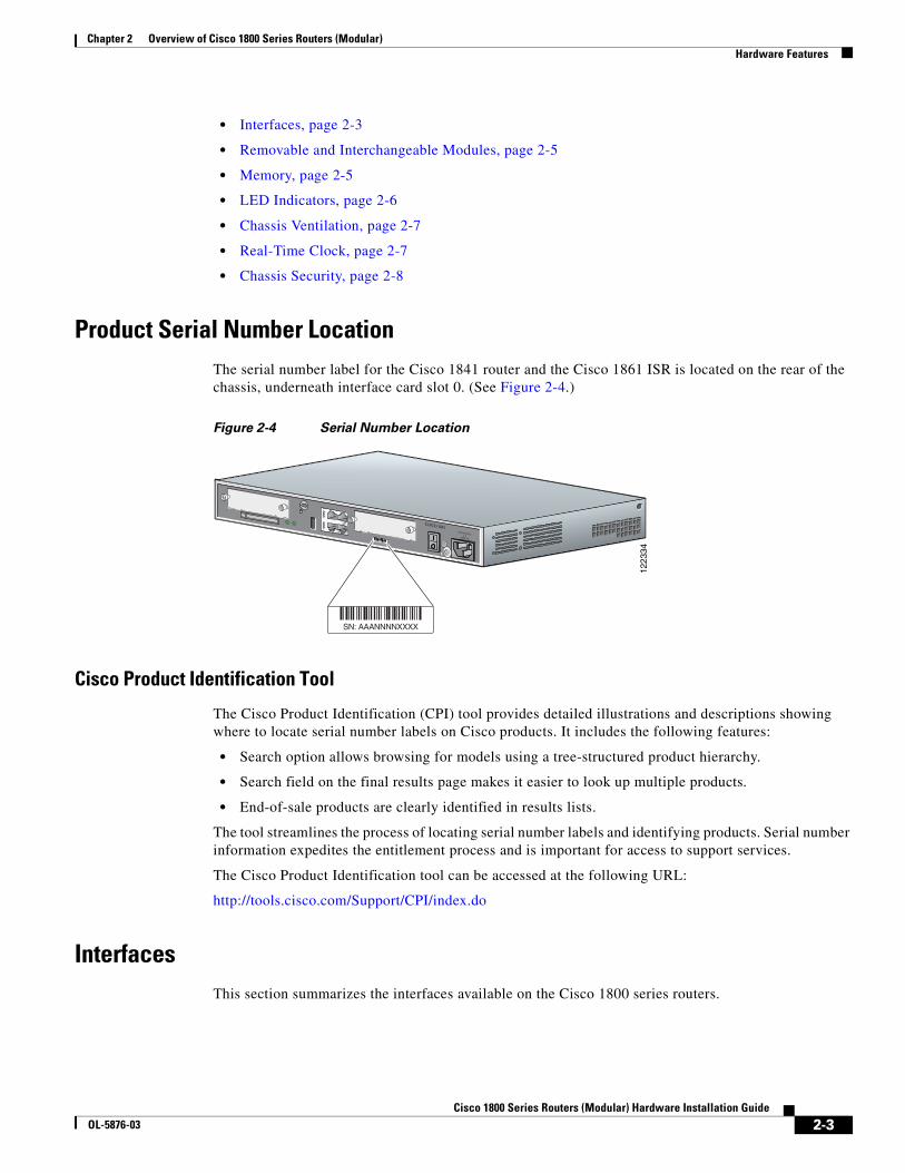
Product Serial Number LocationThe serial number label for the Cisco 1841 router and the Cisco 1861 ISR is located on the rear of the chassis, underneath interface card slot 0. (See Figure 2-4.)
Figure 2-4 Serial Number Location
Cisco Product Identification Tool
The Cisco Product Identification (CPI) tool provides detailed illustrations and descriptions showing where to locate serial number labels on Cisco products. It includes the following features:
• Search option allows browsing for models using a tree-structured product hierarchy.
• Search field on the final results page makes it easier to look up multiple products.
• End-of-sale products are clearly identified in results lists.
The tool streamlines the process of locating serial number labels and identifying products. Serial number information expedites the entitlement process and is important for access to support services.
The Cisco Product Identification tool can be accessed at the following URL:
http://tools.cisco.com/Support/CPI/index.do
InterfacesThis section summarizes the interfaces available on the Cisco 1800 series routers.
1223
34
SN: AAANNNNXXXX
SN: AAANNNNXXXX
CISCO 1841100-240 VAC-1 A
50/60 Hz
2-3Cisco 1800 Series Routers (Modular) Hardware Installation Guide
OL-5876-03
Chapter 2 Overview of Cisco 1800 Series Routers (Modular) Hardware Features
Interfaces on the Cisco 1841 Router
The following interfaces exist on the Cisco 1841 router:
• Two Fast Ethernet ports (RJ-45 connectors)
• High-speed console and auxiliary ports, up to 115.2 kbps each (RJ-45 connectors)
• One USB port (version 1.1), intended for future use
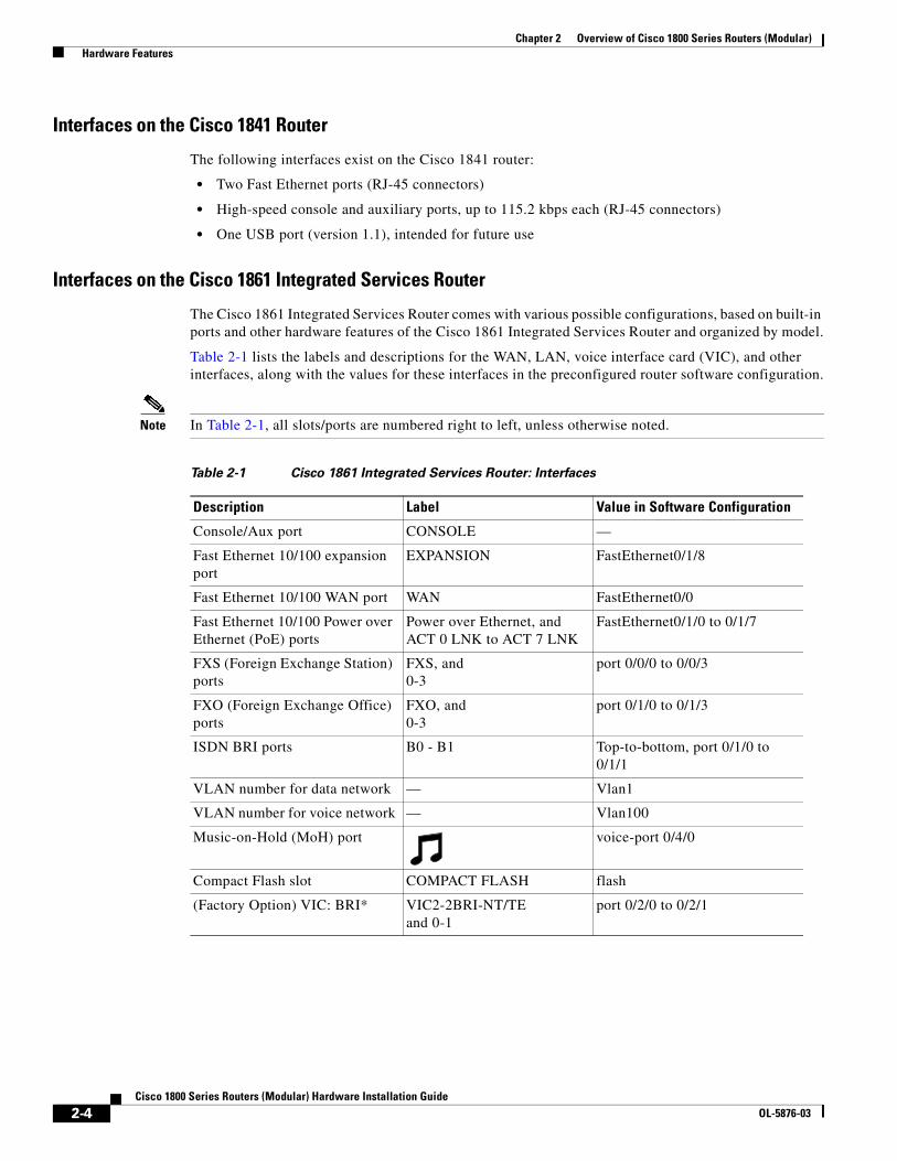
Interfaces on the Cisco 1861 Integrated Services Router
The Cisco 1861 Integrated Services Router comes with various possible configurations, based on built-in ports and other hardware features of the Cisco 1861 Integrated Services Router and organized by model.
Table 2-1 lists the labels and descriptions for the WAN, LAN, voice interface card (VIC), and other interfaces, along with the values for these interfaces in the preconfigured router software configuration.
Note In Table 2-1, all slots/ports are numbered right to left, unless otherwise noted.
Table 2-1 Cisco 1861 Integrated Services Router: Interfaces
Description Label Value in Software Configuration
Console/Aux port CONSOLE —
Fast Ethernet 10/100 expansion port
EXPANSION FastEthernet0/1/8
Fast Ethernet 10/100 WAN port WAN FastEthernet0/0
Fast Ethernet 10/100 Power over Ethernet (PoE) ports
Power over Ethernet, and ACT 0 LNK to ACT 7 LNK
FastEthernet0/1/0 to 0/1/7
FXS (Foreign Exchange Station) ports
FXS, and 0-3
port 0/0/0 to 0/0/3
FXO (Foreign Exchange Office) ports
FXO, and 0-3
port 0/1/0 to 0/1/3
ISDN BRI ports B0 - B1 Top-to-bottom, port 0/1/0 to 0/1/1
VLAN number for data network — Vlan1
VLAN number for voice network — Vlan100
Music-on-Hold (MoH) port voice-port 0/4/0
Compact Flash slot COMPACT FLASH flash
(Factory Option) VIC: BRI* VIC2-2BRI-NT/TE and 0-1
port 0/2/0 to 0/2/1
2-4Cisco 1800 Series Routers (Modular) Hardware Installation Guide
OL-5876-03
Chapter 2 Overview of Cisco 1800 Series Routers (Modular) Hardware Features
* Only one optional VIC can be factory installed in a Cisco 1861 Integrated Services Router.
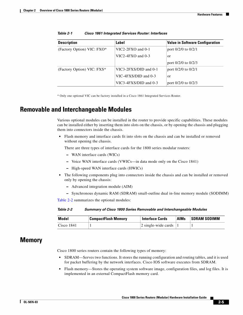
Removable and Interchangeable ModulesVarious optional modules can be installed in the router to provide specific capabilities. These modules can be installed either by inserting them into slots on the chassis, or by opening the chassis and plugging them into connectors inside the chassis.
• Flash memory and interface cards fit into slots on the chassis and can be installed or removed without opening the chassis.
There are three types of interface cards for the 1800 series modular routers:
– WAN interface cards (WICs)
– Voice WAN interface cards (VWICs—in data mode only on the Cisco 1841)
– High-speed WAN interface cards (HWICs)
• The following components plug into connectors inside the chassis and can be installed or removed only by opening the chassis:
– Advanced integration module (AIM)
– Synchronous dynamic RAM (SDRAM) small-outline dual in-line memory module (SODIMM)
Table 2-2 summarizes the optional modules:
MemoryCisco 1800 series routers contain the following types of memory:
• SDRAM—Serves two functions. It stores the running configuration and routing tables, and it is used for packet buffering by the network interfaces. Cisco IOS software executes from SDRAM.
• Flash memory—Stores the operating system software image, configuration files, and log files. It is implemented in an external CompactFlash memory card.
(Factory Option) VIC: FXO* VIC2-2FXO and 0-1
VIC2-4FXO and 0-3
port 0/2/0 to 0/2/1
or
port 0/2/0 to 0/2/3
(Factory Option) VIC: FXS* VIC3-2FXS/DID and 0-1
VIC-4FXS/DID and 0-3
VIC3-4FXS/DID and 0-3
port 0/2/0 to 0/2/1
or
port 0/2/0 to 0/2/3
Table 2-1 Cisco 1861 Integrated Services Router: Interfaces
Description Label Value in Software Configuration
Table 2-2 Summary of Cisco 1800 Series Removable and Interchangeable Modules
Model CompactFlash Memory Interface Cards AIMs SDRAM SODIMM
Cisco 1841 1 2 single-wide cards 1 1
2-5Cisco 1800 Series Routers (Modular) Hardware Installation Guide
OL-5876-03
Chapter 2 Overview of Cisco 1800 Series Routers (Modular) Hardware Features
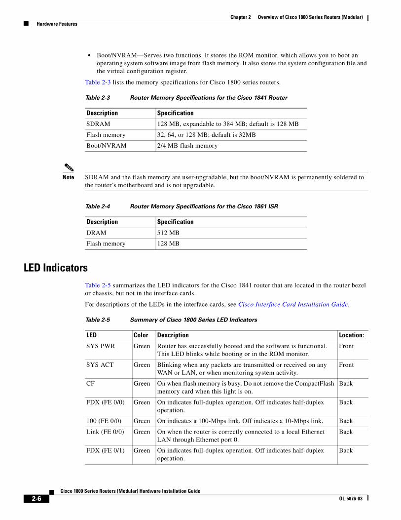
• Boot/NVRAM—Serves two functions. It stores the ROM monitor, which allows you to boot an operating system software image from flash memory. It also stores the system configuration file and the virtual configuration register.
Table 2-3 lists the memory specifications for Cisco 1800 series routers.
Note SDRAM and the flash memory are user-upgradable, but the boot/NVRAM is permanently soldered to the router’s motherboard and is not upgradable.
LED IndicatorsTable 2-5 summarizes the LED indicators for the Cisco 1841 router that are located in the router bezel or chassis, but not in the interface cards.
For descriptions of the LEDs in the interface cards, see Cisco Interface Card Installation Guide.
Table 2-3 Router Memory Specifications for the Cisco 1841 Router
Description Specification
SDRAM 128 MB, expandable to 384 MB; default is 128 MB
Flash memory 32, 64, or 128 MB; default is 32MB
Boot/NVRAM 2/4 MB flash memory
Table 2-4 Router Memory Specifications for the Cisco 1861 ISR
Description Specification
DRAM 512 MB
Flash memory 128 MB
Table 2-5 Summary of Cisco 1800 Series LED Indicators
LED Color Description Location:
SYS PWR Green Router has successfully booted and the software is functional. This LED blinks while booting or in the ROM monitor.
Front
SYS ACT Green Blinking when any packets are transmitted or received on any WAN or LAN, or when monitoring system activity.
Front
CF Green On when flash memory is busy. Do not remove the CompactFlash memory card when this light is on.
Back
FDX (FE 0/0) Green On indicates full-duplex operation. Off indicates half-duplex operation.
Back
100 (FE 0/0) Green On indicates a 100-Mbps link. Off indicates a 10-Mbps link. Back
Link (FE 0/0) Green On when the router is correctly connected to a local Ethernet LAN through Ethernet port 0.
Back
FDX (FE 0/1) Green On indicates full-duplex operation. Off indicates half-duplex operation.
Back
2-6Cisco 1800 Series Routers (Modular) Hardware Installation Guide
OL-5876-03
Chapter 2 Overview of Cisco 1800 Series Routers (Modular) Hardware Features
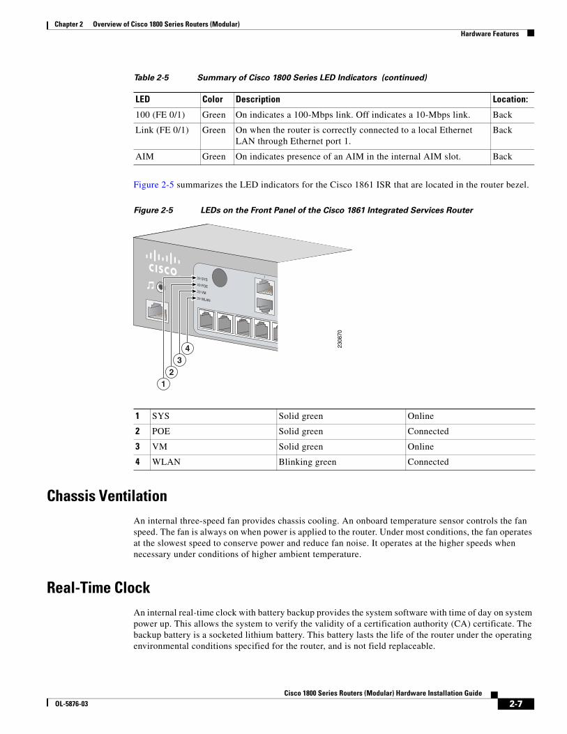
Figure 2-5 summarizes the LED indicators for the Cisco 1861 ISR that are located in the router bezel.
Figure 2-5 LEDs on the Front Panel of the Cisco 1861 Integrated Services Router
Chassis VentilationAn internal three-speed fan provides chassis cooling. An onboard temperature sensor controls the fan speed. The fan is always on when power is applied to the router. Under most conditions, the fan operates at the slowest speed to conserve power and reduce fan noise. It operates at the higher speeds when necessary under conditions of higher ambient temperature.
Real-Time ClockAn internal real-time clock with battery backup provides the system software with time of day on system power up. This allows the system to verify the validity of a certification authority (CA) certificate. The backup battery is a socketed lithium battery. This battery lasts the life of the router under the operating environmental conditions specified for the router, and is not field replaceable.
100 (FE 0/1) Green On indicates a 100-Mbps link. Off indicates a 10-Mbps link. Back
Link (FE 0/1) Green On when the router is correctly connected to a local Ethernet LAN through Ethernet port 1.
Back
AIM Green On indicates presence of an AIM in the internal AIM slot. Back
Table 2-5 Summary of Cisco 1800 Series LED Indicators (continued)
LED Color Description Location:
1 SYS Solid green Online
2 POE Solid green Connected
3 VM Solid green Online
4 WLAN Blinking green Connected
2308
70
1SYS
POE
VM
WLAN
43
21
2-7Cisco 1800 Series Routers (Modular) Hardware Installation Guide
OL-5876-03
Chapter 2 Overview of Cisco 1800 Series Routers (Modular) Chassis Views
Note If the lithium battery in a Cisco 1841 router should fail, the router must be returned to Cisco for repair. Do not replace the battery yourself. Although the battery is not intended to be field replaceable, the safety agencies require the following warning be included in this document.
Warning There is the danger of explosion if the battery is replaced incorrectly. Replace the battery only with the same or equivalent type recommended by the manufacturer. Dispose of used batteries according to the manufacturer’s instructions. Statement 1015
Chassis SecurityThe chassis of the Cisco 1841 router is constructed with a KensingtonTM security slot on the back panel. It can be secured to a desktop or other surface by using KensingtonTM lockdown equipment.
Chassis ViewsThis section contains views of the front and rear panels of Cisco 1841 router, showing the locations of the power and signal interfaces, the interface card slots, and the status indicators.
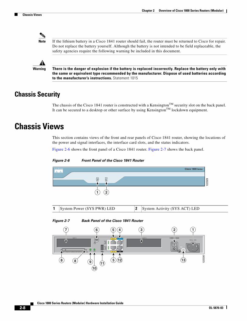
Figure 2-6 shows the front panel of a Cisco 1841 router. Figure 2-7 shows the back panel.
Figure 2-6 Front Panel of the Cisco 1841 Router
Figure 2-7 Back Panel of the Cisco 1841 Router
1 System Power (SYS PWR) LED 2 System Activity (SYS ACT) LED12
2329
1 2
SYSPWR
SYSACT
Cisco 1800 Series
1223
30
FE 0/0 AUX
FE 0/1 CONSOLE CISCO 1841
DO NOT REMOVE DURING NETWORK OPERATIONCF AIM
FDX100
LINK
FDX100
LINK
100-240 VAC-1 A
50/60 Hz
SLOT 0SLOT 1
37 46 5 12
88 9 125 1311
10
2-8Cisco 1800 Series Routers (Modular) Hardware Installation Guide
OL-5876-03
Chapter 2 Overview of Cisco 1800 Series Routers (Modular) Interface Numbering
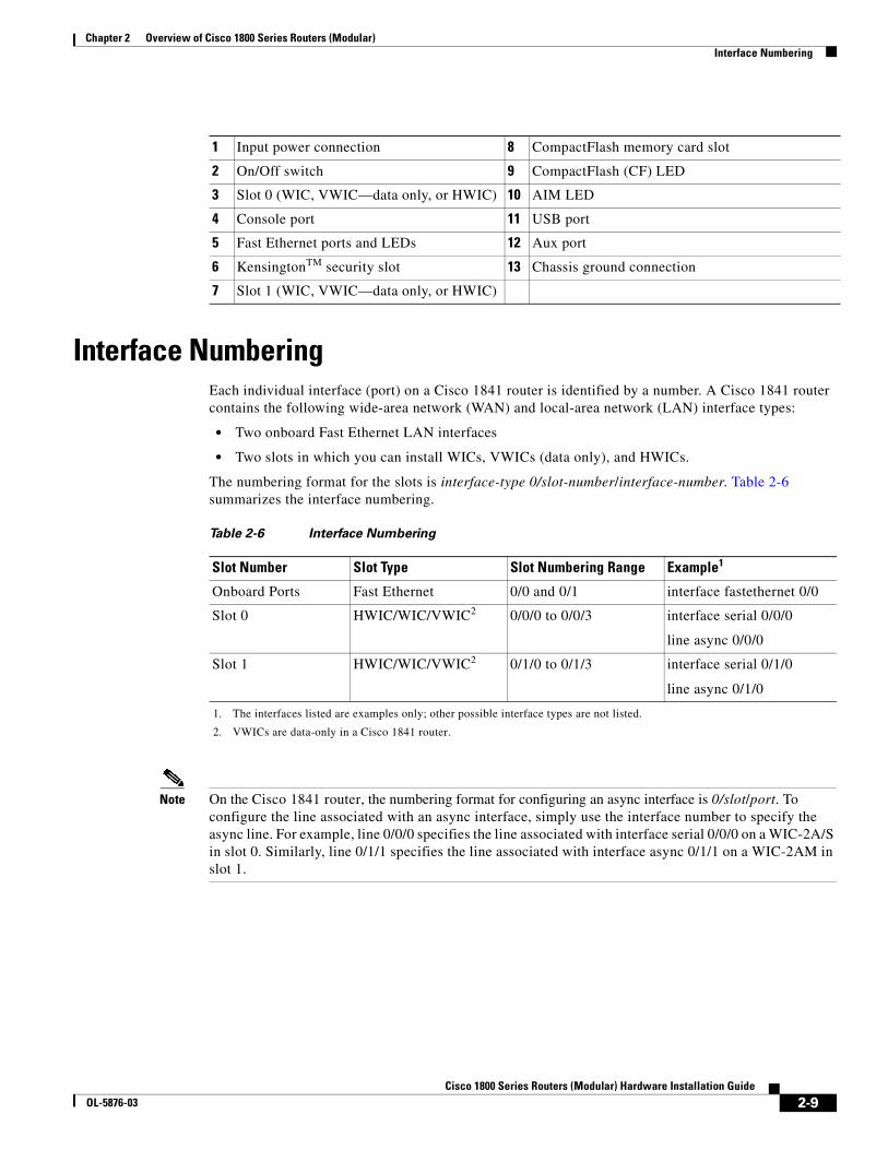
Interface NumberingEach individual interface (port) on a Cisco 1841 router is identified by a number. A Cisco 1841 router contains the following wide-area network (WAN) and local-area network (LAN) interface types:
• Two onboard Fast Ethernet LAN interfaces
• Two slots in which you can install WICs, VWICs (data only), and HWICs.
The numbering format for the slots is interface-type 0/slot-number/interface-number. Table 2-6 summarizes the interface numbering.
Note On the Cisco 1841 router, the numbering format for configuring an async interface is 0/slot/port. To configure the line associated with an async interface, simply use the interface number to specify the async line. For example, line 0/0/0 specifies the line associated with interface serial 0/0/0 on a WIC-2A/S in slot 0. Similarly, line 0/1/1 specifies the line associated with interface async 0/1/1 on a WIC-2AM in slot 1.
1 Input power connection 8 CompactFlash memory card slot
2 On/Off switch 9 CompactFlash (CF) LED
3 Slot 0 (WIC, VWIC—data only, or HWIC) 10 AIM LED
4 Console port 11 USB port
5 Fast Ethernet ports and LEDs 12 Aux port
6 KensingtonTM security slot 13 Chassis ground connection
7 Slot 1 (WIC, VWIC—data only, or HWIC)
Table 2-6 Interface Numbering
Slot Number Slot Type Slot Numbering Range Example1
1. The interfaces listed are examples only; other possible interface types are not listed.
Onboard Ports Fast Ethernet 0/0 and 0/1 interface fastethernet 0/0
Slot 0 HWIC/WIC/VWIC2
2. VWICs are data-only in a Cisco 1841 router.
0/0/0 to 0/0/3 interface serial 0/0/0
line async 0/0/0
Slot 1 HWIC/WIC/VWIC2 0/1/0 to 0/1/3 interface serial 0/1/0
line async 0/1/0
2-9Cisco 1800 Series Routers (Modular) Hardware Installation Guide
OL-5876-03
Chapter 2 Overview of Cisco 1800 Series Routers (Modular) Interface Numbering on the 1861 Integrated Services Router
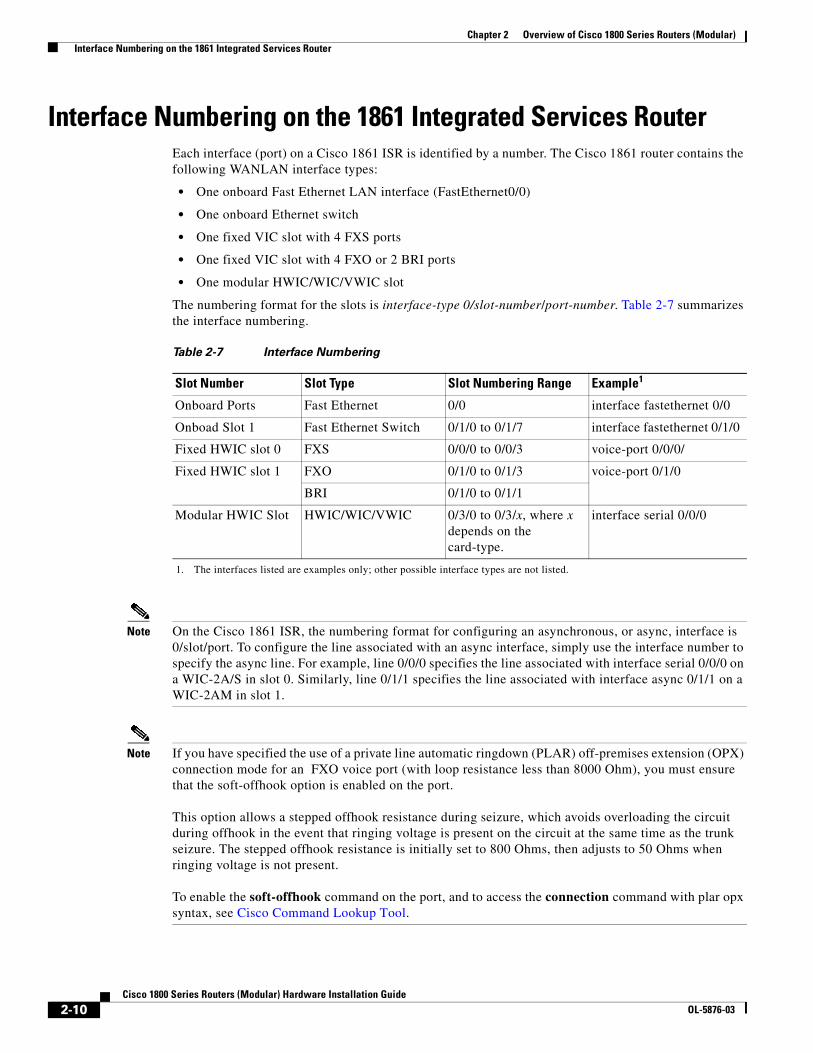
Interface Numbering on the 1861 Integrated Services RouterEach interface (port) on a Cisco 1861 ISR is identified by a number. The Cisco 1861 router contains the following WANLAN interface types:
• One onboard Fast Ethernet LAN interface (FastEthernet0/0)
• One onboard Ethernet switch
• One fixed VIC slot with 4 FXS ports
• One fixed VIC slot with 4 FXO or 2 BRI ports
• One modular HWIC/WIC/VWIC slot
The numbering format for the slots is interface-type 0/slot-number/port-number. Table 2-7 summarizes the interface numbering.
Note On the Cisco 1861 ISR, the numbering format for configuring an asynchronous, or async, interface is 0/slot/port. To configure the line associated with an async interface, simply use the interface number to specify the async line. For example, line 0/0/0 specifies the line associated with interface serial 0/0/0 on a WIC-2A/S in slot 0. Similarly, line 0/1/1 specifies the line associated with interface async 0/1/1 on a WIC-2AM in slot 1.
Note If you have specified the use of a private line automatic ringdown (PLAR) off-premises extension (OPX) connection mode for an FXO voice port (with loop resistance less than 8000 Ohm), you must ensure that the soft-offhook option is enabled on the port. This option allows a stepped offhook resistance during seizure, which avoids overloading the circuit during offhook in the event that ringing voltage is present on the circuit at the same time as the trunk seizure. The stepped offhook resistance is initially set to 800 Ohms, then adjusts to 50 Ohms when ringing voltage is not present. To enable the soft-offhook command on the port, and to access the connection command with plar opx syntax, see Cisco Command Lookup Tool.
Table 2-7 Interface Numbering
Slot Number Slot Type Slot Numbering Range Example1
1. The interfaces listed are examples only; other possible interface types are not listed.
Onboard Ports Fast Ethernet 0/0 interface fastethernet 0/0
Onboad Slot 1 Fast Ethernet Switch 0/1/0 to 0/1/7 interface fastethernet 0/1/0
Fixed HWIC slot 0 FXS 0/0/0 to 0/0/3 voice-port 0/0/0/
Fixed HWIC slot 1 FXO 0/1/0 to 0/1/3 voice-port 0/1/0
BRI 0/1/0 to 0/1/1
Modular HWIC Slot HWIC/WIC/VWIC 0/3/0 to 0/3/x, where x depends on the card-type.
interface serial 0/0/0
2-10Cisco 1800 Series Routers (Modular) Hardware Installation Guide
OL-5876-03
Chapter 2 Overview of Cisco 1800 Series Routers (Modular) Specifications
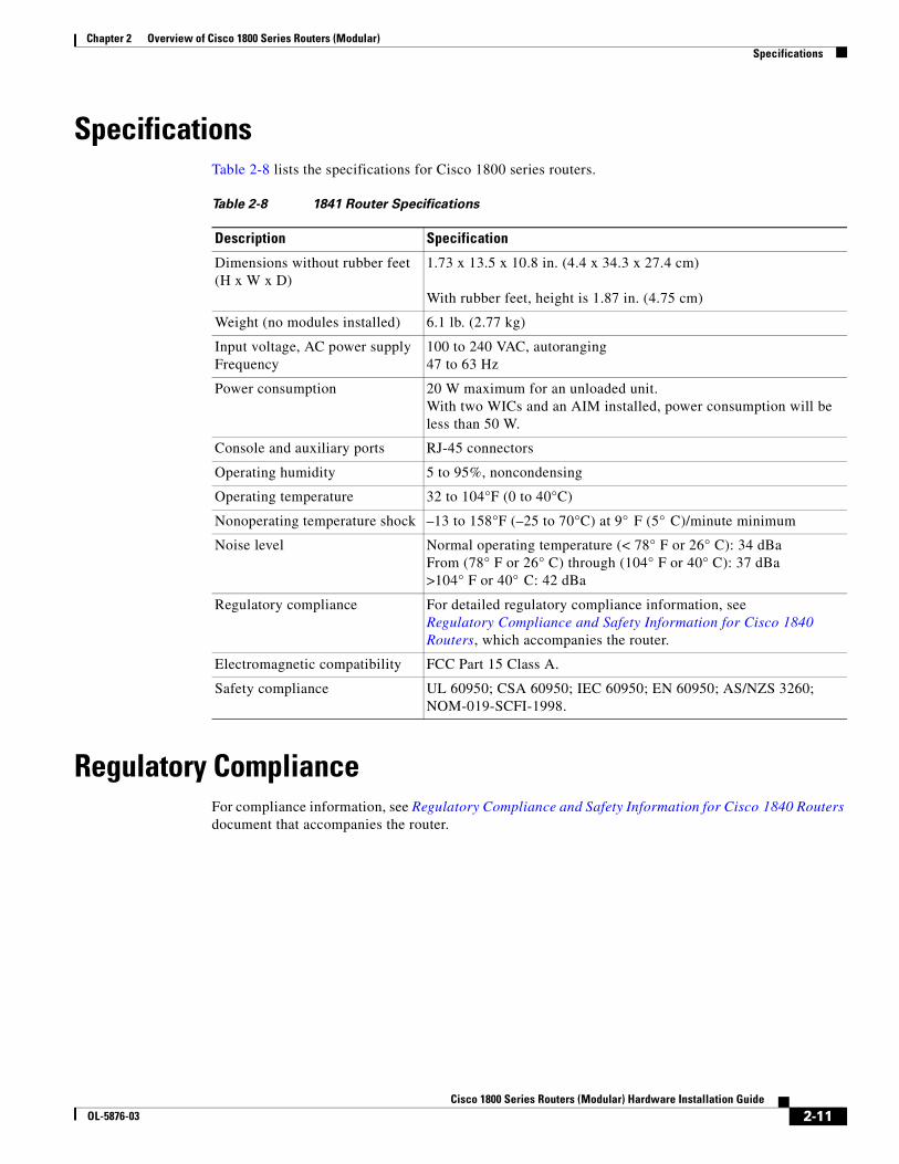
SpecificationsTable 2-8 lists the specifications for Cisco 1800 series routers.
Regulatory ComplianceFor compliance information, see Regulatory Compliance and Safety Information for Cisco 1840 Routers document that accompanies the router.
Table 2-8 1841 Router Specifications
Description Specification
Dimensions without rubber feet (H x W x D)
1.73 x 13.5 x 10.8 in. (4.4 x 34.3 x 27.4 cm) With rubber feet, height is 1.87 in. (4.75 cm)
Weight (no modules installed) 6.1 lb. (2.77 kg)
Input voltage, AC power supply Frequency
100 to 240 VAC, autoranging 47 to 63 Hz
Power consumption 20 W maximum for an unloaded unit. With two WICs and an AIM installed, power consumption will be less than 50 W.
Console and auxiliary ports RJ-45 connectors
Operating humidity 5 to 95%, noncondensing
Operating temperature 32 to 104°F (0 to 40°C)
Nonoperating temperature shock –13 to 158°F (–25 to 70°C) at 9° F (5° C)/minute minimum
Noise level Normal operating temperature (< 78° F or 26° C): 34 dBa From (78° F or 26° C) through (104° F or 40° C): 37 dBa >104° F or 40° C: 42 dBa
Regulatory compliance For detailed regulatory compliance information, see Regulatory Compliance and Safety Information for Cisco 1840 Routers, which accompanies the router.
Electromagnetic compatibility FCC Part 15 Class A.
Safety compliance UL 60950; CSA 60950; IEC 60950; EN 60950; AS/NZS 3260; NOM-019-SCFI-1998.
2-11Cisco 1800 Series Routers (Modular) Hardware Installation Guide
OL-5876-03

Chapter 2 Overview of Cisco 1800 Series Routers (Modular) Regulatory Compliance
2-12Cisco 1800 Series Routers (Modular) Hardware Installation Guide
OL-5876-03
Cisco 1800 SeOL-5876-03
C H A P T E R 3
Preinstallation Requirements and Planning for Cisco 1800 Series Routers (Modular)This chapter describes the site requirements and equipment needed to install your Cisco 1800 series integrated services router (modular). It includes the following sections:
• Safety Recommendations, page 3-1
• General Site Requirements, page 3-3
• Installation Checklist, page 3-4
• Site Log, page 3-5
• Inspecting the Router, page 3-6
• Required Tools and Equipment for Installation and Maintenance, page 3-7
Note To see translations of the warnings that appear in this publication, see Regulatory Compliance and Safety Information for Cisco 1840 Routers.
Safety RecommendationsFollow these guidelines to ensure general safety:
• Keep the chassis area clear and dust-free during and after installation.
• If you remove the chassis cover, put it in a safe place.
• Keep tools and chassis components away from walk areas.
• Do not wear loose clothing that could get caught in the chassis. Fasten your tie or scarf, and roll up your sleeves.
• Wear safety glasses when working under conditions that might be hazardous to your eyes.
• Do not perform any action that creates a hazard to people or makes the equipment unsafe.
Warning Read the installation instructions before connecting the system to the power source. Statement 1004
3-1ries Routers (Modular) Hardware Installation Guide
Chapter 3 Preinstallation Requirements and Planning for Cisco 1800 Series Routers (Modular) Safety Recommendations
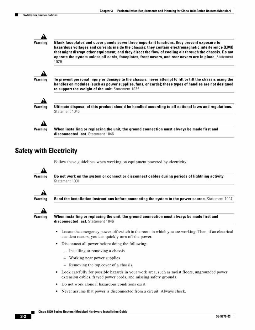
Warning Blank faceplates and cover panels serve three important functions: they prevent exposure to hazardous voltages and currents inside the chassis; they contain electromagnetic interference (EMI) that might disrupt other equipment; and they direct the flow of cooling air through the chassis. Do not operate the system unless all cards, faceplates, front covers, and rear covers are in place. Statement 1029
Warning To prevent personal injury or damage to the chassis, never attempt to lift or tilt the chassis using the handles on modules (such as power supplies, fans, or cards); these types of handles are not designed to support the weight of the unit. Statement 1032
Warning Ultimate disposal of this product should be handled according to all national laws and regulations. Statement 1040
Warning When installing or replacing the unit, the ground connection must always be made first and disconnected last. Statement 1046
Safety with ElectricityFollow these guidelines when working on equipment powered by electricity.
Warning Do not work on the system or connect or disconnect cables during periods of lightning activity. Statement 1001
Warning Read the installation instructions before connecting the system to the power source. Statement 1004
Warning When installing or replacing the unit, the ground connection must always be made first and disconnected last. Statement 1046
• Locate the emergency power-off switch in the room in which you are working. Then, if an electrical accident occurs, you can quickly turn off the power.
• Disconnect all power before doing the following:
– Installing or removing a chassis
– Working near power supplies
– Removing the top cover of a chassis
• Look carefully for possible hazards in your work area, such as moist floors, ungrounded power extension cables, frayed power cords, and missing safety grounds.
• Do not work alone if hazardous conditions exist.
• Never assume that power is disconnected from a circuit. Always check.
3-2Cisco 1800 Series Routers (Modular) Hardware Installation Guide
OL-5876-03
Chapter 3 Preinstallation Requirements and Planning for Cisco 1800 Series Routers (Modular) General Site Requirements
• Never open the enclosure of the router’s internal power supply.
• If an electrical accident occurs, proceed as follows:
– Use caution; do not become a victim yourself.
– Turn off power to the device.
– If possible, send another person to get medical aid. Otherwise, assess the victim’s condition and then call for help.
– Determine whether the person needs rescue breathing or external cardiac compressions; then take appropriate action.
In addition, use the following guidelines when working with any equipment that is disconnected from a power source, but is still connected to telephone wiring or other network cabling:
• Never install telephone wiring during a lightning storm.
• Never install telephone jacks in wet locations unless the jack is specifically designed for it.
• Never touch uninsulated telephone wires or terminals unless the telephone line is disconnected at the network interface.
• Use caution when installing or modifying telephone lines.
Preventing Electrostatic Discharge Damage Electrostatic discharge (ESD) can damage equipment and impair electrical circuitry. ESD can occur if electronic printed circuit cards are improperly handled and can cause complete or intermittent failures. Always follow ESD prevention procedures when removing and replacing modules:
• Ensure that the router chassis is electrically connected to earth ground.
• Wear an ESD-preventive wrist strap, ensuring that it makes good skin contact. Connect the clip to an unpainted surface of the chassis frame to channel unwanted ESD voltages safely to ground. To guard against ESD damage and shocks, the wrist strap and cord must operate effectively.
• If no wrist strap is available, ground yourself by touching a metal part of the chassis.
Caution For the safety of your equipment, periodically check the resistance value of the antistatic strap. It should be between 1 and 10 megohms (Mohm).
General Site RequirementsThis section describes the requirements that your site must meet for safe installation and operation of your router. Ensure that the site is properly prepared before beginning installation. If you are experiencing shutdowns or unusually high errors with your existing equipment, this section can also help you isolate the cause of failures and prevent future problems.
Power Supply ConsiderationsCheck the power at your site to ensure that you are receiving “clean” power (free of spikes and noise). Install a power conditioner if necessary.
3-3Cisco 1800 Series Routers (Modular) Hardware Installation Guide
OL-5876-03
Chapter 3 Preinstallation Requirements and Planning for Cisco 1800 Series Routers (Modular) Installation Checklist
Warning The device is designed for connection to TN and IT power systems. Statement 1007
The AC power supply includes the following features:
• Autoselects either 110 V or 220 V operation.
• All units include a 6-foot (1.8-meter) electrical power cord. (A label near the power cord indicates the correct voltage, frequency, current draw, and power dissipation for the unit.)
Site EnvironmentThe location of your router is an extremely important consideration for proper operation. Equipment placed too close together-, or with inadequate ventilation-, or with inaccessible panels, can cause malfunctions and shutdowns, and can also make maintenance difficult. Plan for access to both front and back panels of the router.
When planning your site layout and equipment locations, remember the precautions described in the “Site Configuration” section on page 3-4 to help avoid equipment failures and reduce the possibility of environmentally caused shutdowns. If you are currently experiencing shutdowns or an unusually high number of errors with your existing equipment, these precautions may help you isolate the cause of the failures and prevent future problems.
Site ConfigurationThe following precautions will help you plan an acceptable operating environment for your router and will help you avoid environmentally caused equipment failures:
• Make sure that the room where your router operates has adequate circulation. Electrical equipment generates heat. Without adequate circulation, ambient air temperature may not cool equipment to acceptable operating temperatures.
• Always follow the ESD-prevention procedures described in the “Preventing Electrostatic Discharge Damage” section on page 3-3 to avoid damage to equipment. Damage from static discharge can cause immediate or intermittent equipment failure.
• Make sure that the chassis cover and module back panels are secure. All empty interface card slots must have filler panels installed. The chassis is designed to allow cooling air to flow within it, through specially designed cooling slots. A chassis with uncovered openings creates air leaks, which may interrupt and reduce the flow of air across internal components.
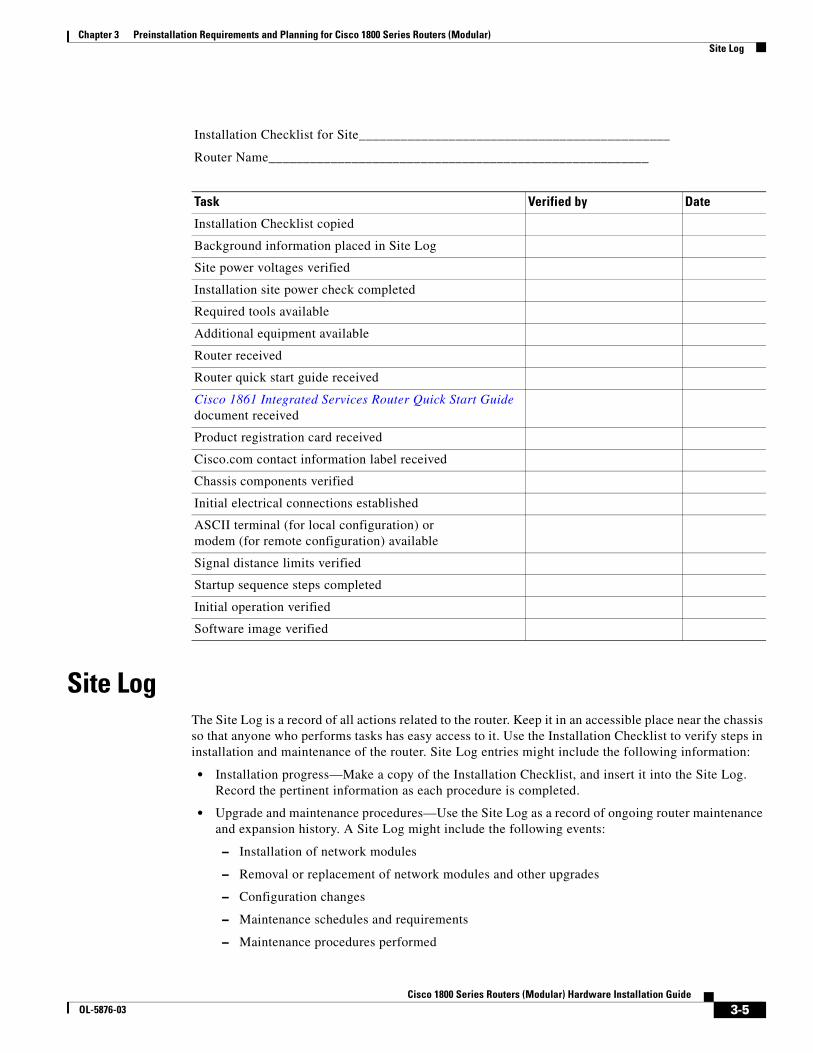
Installation ChecklistThe sample installation checklist lists items and procedures for installing a new router. Make a copy of this checklist, and mark each item when you complete it. Include a copy of the checklist for each router in your Site Log (described in the “Site Log” section on page 3-5).
3-4Cisco 1800 Series Routers (Modular) Hardware Installation Guide
OL-5876-03
Chapter 3 Preinstallation Requirements and Planning for Cisco 1800 Series Routers (Modular) Site Log
Site LogThe Site Log is a record of all actions related to the router. Keep it in an accessible place near the chassis so that anyone who performs tasks has easy access to it. Use the Installation Checklist to verify steps in installation and maintenance of the router. Site Log entries might include the following information:
• Installation progress—Make a copy of the Installation Checklist, and insert it into the Site Log. Record the pertinent information as each procedure is completed.
• Upgrade and maintenance procedures—Use the Site Log as a record of ongoing router maintenance and expansion history. A Site Log might include the following events:
– Installation of network modules
– Removal or replacement of network modules and other upgrades
– Configuration changes
– Maintenance schedules and requirements
– Maintenance procedures performed
Installation Checklist for Site_____________________________________________
Router Name_______________________________________________________
Task Verified by Date
Installation Checklist copied
Background information placed in Site Log
Site power voltages verified
Installation site power check completed
Required tools available
Additional equipment available
Router received
Router quick start guide received
Cisco 1861 Integrated Services Router Quick Start Guide document received
Product registration card received
Cisco.com contact information label received
Chassis components verified
Initial electrical connections established
ASCII terminal (for local configuration) or modem (for remote configuration) available
Signal distance limits verified
Startup sequence steps completed
Initial operation verified
Software image verified
3-5Cisco 1800 Series Routers (Modular) Hardware Installation Guide
OL-5876-03
Chapter 3 Preinstallation Requirements and Planning for Cisco 1800 Series Routers (Modular) Inspecting the Router
– Intermittent problems
– Comments and notes
Inspecting the RouterDo not unpack the router until you are ready to install it. If the final installation site will not be ready for some time, keep the chassis in its shipping container to prevent accidental damage. When you are ready to install the router, proceed with unpacking it.
Items in the Box for the Cisco 1841 RouterThe router, cables, publications, and any optional equipment that you ordered may be shipped in more than one container. When you unpack the containers, check the packing list to ensure that you have received all the following items:
• Router
• 6-foot (1.8-meter) power cord
• Ground lug
• RJ-45-to-DB-9 console cable
• DB-9-to-DB-25 modem adapter
• Cisco 1800 Series Integrated Services Routers (Modular) Quick Start Guide
• Regulatory Compliance and Safety Information for Cisco 1840 Routers
• Cisco Router and Security Device Manager (SDM) Quick Start Guide
• Cisco.com card
• Product registration card
Inspect all items for shipping damage. If anything appears to be damaged, or if you encounter problems installing or configuring your router, contact customer service.
Items in the Box for the Cisco 1861 Integrated Services RouterThe following items ship with the Cisco 1861 Integrated Services Router:
• Accessory kit containing:
– Rubber feet for desktop installation
– RJ-45-to-RJ-45 Ethernet cable
– Light blue RJ-45-to-DB9 console cable
– Wall-mount bracket for power supply
– Quick Start Guide for Cisco 1861 Integrated Services Router (this guide)
– Regulatory Compliance and Safety Information Roadmap
A separate rack-mount kit can be ordered which includes the following:
– Power supply bracket
– Rack-mount brackets for chassis
3-6Cisco 1800 Series Routers (Modular) Hardware Installation Guide
OL-5876-03
Chapter 3 Preinstallation Requirements and Planning for Cisco 1800 Series Routers (Modular) Required Tools and Equipment for Installation and Maintenance
– Assembly hardware (screws)
– Installing Components for Cisco 1861 Integrated Services Router
Inspect all items for shipping damage. If anything appears to be damaged, or if you encounter problems installing or configuring your router, contact customer service.
Items not Included in the Box for the Cisco 1861 Integrated Services RouterYou may need individual items in this list which are not shipped in the box:
• Cisco Unified IP phones
• Cables for connecting phones
• Cable for connecting external audio device to the 3.5-mm MoH port
• Cables for WAN interfaces, voice interfaces, or additional LAN interfaces
• PC with Microsoft Internet Explorer 6.0 or later, for using web-based system management tools
Required Tools and Equipment for Installation and MaintenanceYou need the following tools and equipment for installing and upgrading the router and its components:
• ESD-preventive cord and wrist strap
• Number 2 Phillips screwdriver
• Flat-blade screwdrivers: small, 3/16-inch (0.48 centimeter) and medium, 1/4-inch (0.63 centimeter)
– For installing or removing modules
– For removing the cover if you are upgrading memory or other components
• Wire crimper
• AWG 14 wire for connecting the router chassis to earth ground
In addition, depending on the type of modules you plan to use, you might need the following equipment to connect a port to an external network:
• Cables for connection to WAN and LAN ports (dependent on configuration)
Note For more information on cable specifications, see the online document Cisco Modular Access Router Cable Specifications, which is located on Cisco.com.
• Ethernet hub or PC with a network interface card for connection to Ethernet (LAN) ports
• Console terminal (an ASCII terminal or a PC running terminal emulation software) configured for 9600 baud, 8 data bits, no parity, and 1 stop bit
• Modem for connection to the auxiliary port for remote administrative access
• Data service unit (DSU) or channel service unit/data service unit (CSU/DSU) as appropriate for serial interfaces
• External CSU for any CT1/PRI modules without a built-in CSU
NT1 device for ISDN BRI S/T interfaces (if not supplied by your service provider)
3-7Cisco 1800 Series Routers (Modular) Hardware Installation Guide
OL-5876-03

Chapter 3 Preinstallation Requirements and Planning for Cisco 1800 Series Routers (Modular) Required Tools and Equipment for Installation and Maintenance
3-8Cisco 1800 Series Routers (Modular) Hardware Installation Guide
OL-5876-03
Cisco 1800 SeOL-5876-03
C H A P T E R 4
Chassis Installation Procedures for Cisco 1800 Series Routers (Modular)This chapter tells how to physically set up Cisco 1800 series integrated services routers (ISR) (modular). It contains the following sections:
• Setting Up the Chassis, page 4-3
• Installing the Chassis Ground Connection, page 4-11
Cisco 1800 series routers are normally shipped with a complement of components that can be upgraded or replaced to expand and enhance the router’s functionality. These components either are inserted internally into the router or are plugged into slots in the router chassis.
Note To see translations of the warnings that appear in this publication, see Regulatory Compliance and Safety Information for Cisco 1840 Routers.
Internal Components
The router’s internal components include the following:
• SDRAM
• Advanced integration module (AIM)
If you need to remove or upgrade either of these items, follow the procedures given in the “Installing and Upgrading Internal Modules in Cisco 1800 Series Routers (Modular)” document.
Plug-In Components
The following components plug into the router chassis:
• WAN interface cards (WICs)
• Voice/WAN interface cards (VWICs), data mode only
• High-speed WICs (HWICs)
• CompactFlash memory card
If you need to remove or install WICs, VWICs, or HWICs, follow the procedures in the “Installing Interface Cards in Cisco 1800 Series Routers (Modular)” document.
If you need to remove or upgrade the CompactFlash memory card, follow the procedure in the “Installing and Replacing CompactFlash Memory Cards on Cisco 1800 Series Routers (Modular)” document.
4-1ries Routers (Modular) Hardware Installation Guide
Chapter 4 Chassis Installation Procedures for Cisco 1800 Series Routers (Modular)
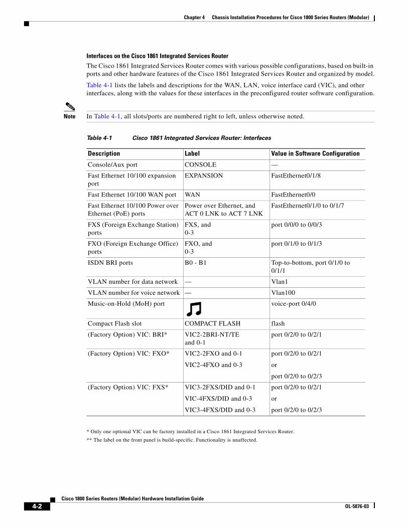
Interfaces on the Cisco 1861 Integrated Services Router
The Cisco 1861 Integrated Services Router comes with various possible configurations, based on built-in ports and other hardware features of the Cisco 1861 Integrated Services Router and organized by model.
Table 4-1 lists the labels and descriptions for the WAN, LAN, voice interface card (VIC), and other interfaces, along with the values for these interfaces in the preconfigured router software configuration.
Note In Table 4-1, all slots/ports are numbered right to left, unless otherwise noted.
* Only one optional VIC can be factory installed in a Cisco 1861 Integrated Services Router.
** The label on the front panel is build-specific. Functionality is unaffected.
Table 4-1 Cisco 1861 Integrated Services Router: Interfaces
Description Label Value in Software Configuration
Console/Aux port CONSOLE —
Fast Ethernet 10/100 expansion port
EXPANSION FastEthernet0/1/8
Fast Ethernet 10/100 WAN port WAN FastEthernet0/0
Fast Ethernet 10/100 Power over Ethernet (PoE) ports
Power over Ethernet, and ACT 0 LNK to ACT 7 LNK
FastEthernet0/1/0 to 0/1/7
FXS (Foreign Exchange Station) ports
FXS, and 0-3
port 0/0/0 to 0/0/3
FXO (Foreign Exchange Office) ports
FXO, and 0-3
port 0/1/0 to 0/1/3
ISDN BRI ports B0 - B1 Top-to-bottom, port 0/1/0 to 0/1/1
VLAN number for data network — Vlan1
VLAN number for voice network — Vlan100
Music-on-Hold (MoH) port voice-port 0/4/0
Compact Flash slot COMPACT FLASH flash
(Factory Option) VIC: BRI* VIC2-2BRI-NT/TE and 0-1
port 0/2/0 to 0/2/1
(Factory Option) VIC: FXO* VIC2-2FXO and 0-1
VIC2-4FXO and 0-3
port 0/2/0 to 0/2/1
or
port 0/2/0 to 0/2/3
(Factory Option) VIC: FXS* VIC3-2FXS/DID and 0-1
VIC-4FXS/DID and 0-3
VIC3-4FXS/DID and 0-3
port 0/2/0 to 0/2/1
or
port 0/2/0 to 0/2/3
4-2Cisco 1800 Series Routers (Modular) Hardware Installation Guide
OL-5876-03
Chapter 4 Chassis Installation Procedures for Cisco 1800 Series Routers (Modular) Setting Up the Chassis
Setting Up the ChassisThe Cisco 1841 router and the Cisco 1861 ISR can be installed on a desktop, and can also be mounted on a wall. Select the setup that best meets the needs of your network. These setups are described in the following sections:
• Setting the Chassis on a Desktop, page 4-3
• Rack-Mounting a Cisco 1800 Series Modular-Configuration Router, page 4-3
• Wall-Mounting the Chassis, page 4-6
Caution The front panel bezel must not be removed from the Cisco 1841 router. It is part of the product's enclosure, and must be left in place to prevent damage from foreign objects entering the router, to provide a shield from internal electromagnetic interference (EMI), and to direct the flow of cooling air properly through the chassis.
Setting the Chassis on a DesktopYou can place Cisco 1841 routers on a desktop or shelf. The Cisco 1841 router is shipped with the rubber feet attached to the chassis to provide space for air circulation.
To install a chassis on a desktop, table, or other flat surface, place the unit upside-down on a flat surface. Attach the four rubber pads to the recessed areas on the bottom of the unit. Place the unit on a desktop.
Warning To prevent personal injury or damage to the chassis, never attempt to lift or tilt the chassis using the handles on modules (such as power supplies, fans, or cards); these types of handles are not designed to support the weight of the unit. Statement 1032
Caution Do not place anything on top of the router that weighs more than 10 lbs (4.5 kg). Excessive weight on top of the router could damage the chassis.
Caution The Cisco 1861 Integrated Services Router installation must allow unrestricted airflow for cooling. For placing the platform on a desktop, keep at least 1 in. (2.54 cm) of clear space beside the cooling inlet and exhaust vents.
Rack-Mounting a Cisco 1800 Series Modular-Configuration RouterIf you are planning to rack-mount the router, rack-mount it before you make the network and power connections. If you need to install any internal modules, such as an expansion DIMM or an inline power supply card, install these prior to rack-mounting.
4-3Cisco 1800 Series Routers (Modular) Hardware Installation Guide
OL-5876-03
Chapter 4 Chassis Installation Procedures for Cisco 1800 Series Routers (Modular) Setting Up the Chassis
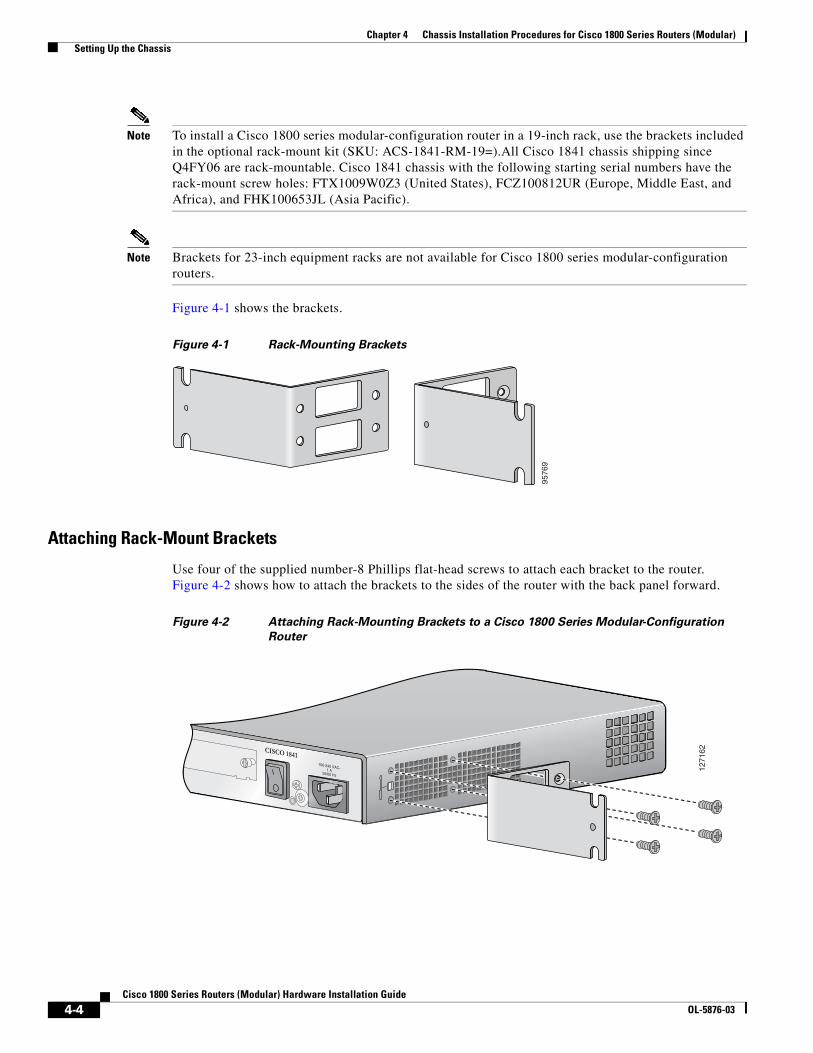
Note To install a Cisco 1800 series modular-configuration router in a 19-inch rack, use the brackets included in the optional rack-mount kit (SKU: ACS-1841-RM-19=).All Cisco 1841 chassis shipping since Q4FY06 are rack-mountable. Cisco 1841 chassis with the following starting serial numbers have the rack-mount screw holes: FTX1009W0Z3 (United States), FCZ100812UR (Europe, Middle East, and Africa), and FHK100653JL (Asia Pacific).
Note Brackets for 23-inch equipment racks are not available for Cisco 1800 series modular-configuration routers.
Figure 4-1 shows the brackets.
Figure 4-1 Rack-Mounting Brackets
Attaching Rack-Mount Brackets
Use four of the supplied number-8 Phillips flat-head screws to attach each bracket to the router. Figure 4-2 shows how to attach the brackets to the sides of the router with the back panel forward.
Figure 4-2 Attaching Rack-Mounting Brackets to a Cisco 1800 Series Modular-Configuration
Router
9576
9
1271
62CISCO 1841100-240 VAC-1 A
50/60 Hz
4-4Cisco 1800 Series Routers (Modular) Hardware Installation Guide
OL-5876-03
Chapter 4 Chassis Installation Procedures for Cisco 1800 Series Routers (Modular) Setting Up the Chassis
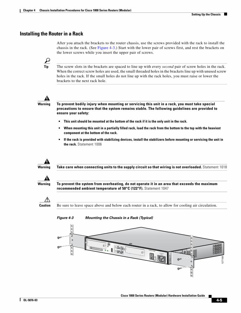
Installing the Router in a Rack
After you attach the brackets to the router chassis, use the screws provided with the rack to install the chassis in the rack. (See Figure 4-3.) Start with the lower pair of screws first, and rest the brackets on the lower screws while you insert the upper pair of screws.
Tip The screw slots in the brackets are spaced to line up with every second pair of screw holes in the rack. When the correct screw holes are used, the small threaded holes in the brackets line up with unused screw holes in the rack. If the small holes do not line up with the rack holes, you must raise or lower the brackets to the next rack hole.
Warning Take care when connecting units to the supply circuit so that wiring is not overloaded. Statement 1018
Warning To prevent the system from overheating, do not operate it in an area that exceeds the maximum recommended ambient temperature of 50°C (122°F). Statement 1047
Caution Be sure to leave space above and below each router in a rack, to allow for cooling air circulation.
Figure 4-3 Mounting the Chassis in a Rack (Typical)
Warning To prevent bodily injury when mounting or servicing this unit in a rack, you must take special precautions to ensure that the system remains stable. The following guidelines are provided to ensure your safety:
• This unit should be mounted at the bottom of the rack if it is the only unit in the rack.
• When mounting this unit in a partially filled rack, load the rack from the bottom to the top with the heaviest component at the bottom of the rack.
• If the rack is provided with stabilizing devices, install the stabilizers before mounting or servicing the unit in the rack. Statement 1006
1271
68
CISCO 1841100-240 VAC-1 A
50/60 Hz
4-5Cisco 1800 Series Routers (Modular) Hardware Installation Guide
OL-5876-03
Chapter 4 Chassis Installation Procedures for Cisco 1800 Series Routers (Modular) Setting Up the Chassis
Chassis Grounding
After the router has been installed, you must connect the chassis to a reliable earth ground. For the chassis ground connection procedure, see the “Wall-Mounting the Cisco 1861 Integrated Services Router” section on page 4-8.
Wall-Mounting the ChassisThe Cisco 1841 router and the Cisco 1861 ISR can be mounted on a wall.
Warning This unit is intended to be mounted on a wall. Please read the wall mounting instructions carefully before beginning installation. Failure to use the correct hardware or to follow the correct procedures could result in a hazardous situation to people and damage to the system. Statement 248
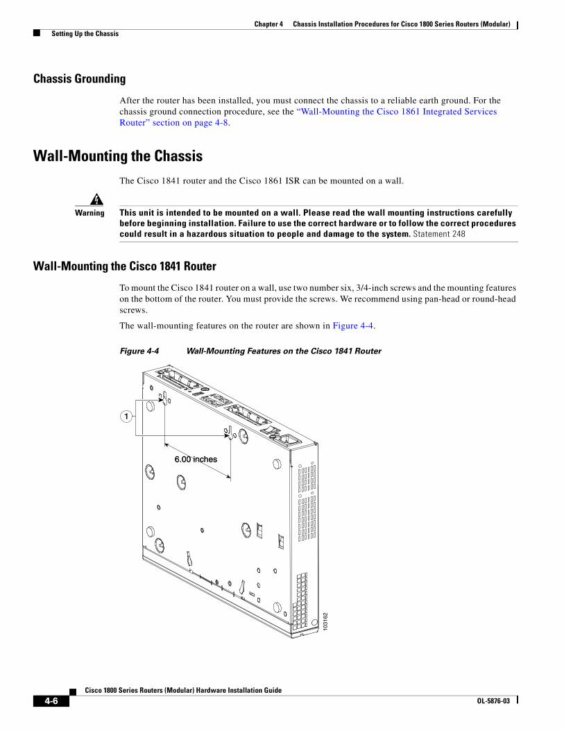
Wall-Mounting the Cisco 1841 Router
To mount the Cisco 1841 router on a wall, use two number six, 3/4-inch screws and the mounting features on the bottom of the router. You must provide the screws. We recommend using pan-head or round-head screws.
The wall-mounting features on the router are shown in Figure 4-4.
Figure 4-4 Wall-Mounting Features on the Cisco 1841 Router
1031
62
11
6.00 inches6.00 inches
4-6Cisco 1800 Series Routers (Modular) Hardware Installation Guide
OL-5876-03
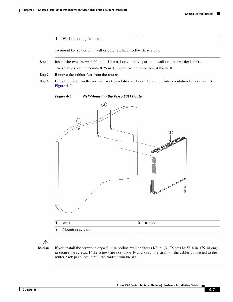
Chapter 4 Chassis Installation Procedures for Cisco 1800 Series Routers (Modular) Setting Up the Chassis
To mount the router on a wall or other surface, follow these steps:
Step 1 Install the two screws 6.00 in. (15.2 cm) horizontally apart on a wall or other vertical surface.
The screws should protrude 0.25 in. (0.6 cm) from the surface of the wall.
Step 2 Remove the rubber feet from the router.
Step 3 Hang the router on the screws, front panel down. This is the appropriate orientation for safe use. See Figure 4-5.
Figure 4-5 Wall-Mounting the Cisco 1841 Router
Caution If you install the screws in drywall, use hollow-wall anchors (1/8 in. (31.75 cm) by 5/16 in. (79.38 cm)) to secure the screws. If the screws are not properly anchored, the strain of the cables connected to the router back panel could pull the router from the wall.
1 Wall-mounting features
1 Wall 3 Router
2 Mounting screws
1031
63
1
2
3
4-7Cisco 1800 Series Routers (Modular) Hardware Installation Guide
OL-5876-03
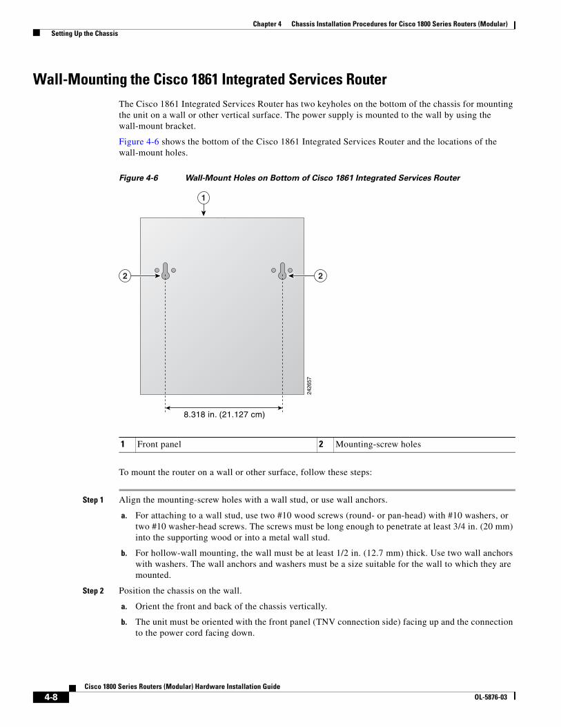
Chapter 4 Chassis Installation Procedures for Cisco 1800 Series Routers (Modular) Setting Up the Chassis
Wall-Mounting the Cisco 1861 Integrated Services RouterThe Cisco 1861 Integrated Services Router has two keyholes on the bottom of the chassis for mounting the unit on a wall or other vertical surface. The power supply is mounted to the wall by using the wall-mount bracket.
Figure 4-6 shows the bottom of the Cisco 1861 Integrated Services Router and the locations of the wall-mount holes.
Figure 4-6 Wall-Mount Holes on Bottom of Cisco 1861 Integrated Services Router
To mount the router on a wall or other surface, follow these steps:
Step 1 Align the mounting-screw holes with a wall stud, or use wall anchors.
a. For attaching to a wall stud, use two #10 wood screws (round- or pan-head) with #10 washers, or two #10 washer-head screws. The screws must be long enough to penetrate at least 3/4 in. (20 mm) into the supporting wood or into a metal wall stud.
b. For hollow-wall mounting, the wall must be at least 1/2 in. (12.7 mm) thick. Use two wall anchors with washers. The wall anchors and washers must be a size suitable for the wall to which they are mounted.
Step 2 Position the chassis on the wall.
a. Orient the front and back of the chassis vertically.
b. The unit must be oriented with the front panel (TNV connection side) facing up and the connection to the power cord facing down.
1 Front panel 2 Mounting-screw holes
2426
57
1
2 2
8.318 in. (21.127 cm)
4-8Cisco 1800 Series Routers (Modular) Hardware Installation Guide
OL-5876-03
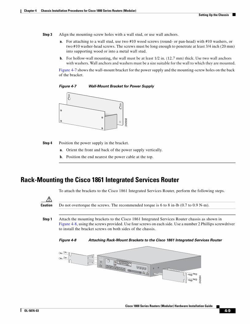
Chapter 4 Chassis Installation Procedures for Cisco 1800 Series Routers (Modular) Setting Up the Chassis
Step 3 Align the mounting-screw holes with a wall stud, or use wall anchors.
a. For attaching to a wall stud, use two #10 wood screws (round- or pan-head) with #10 washers, or two #10 washer-head screws. The screws must be long enough to penetrate at least 3/4 inch (20 mm) into supporting wood or into a metal wall stud.
b. For hollow-wall mounting, the wall must be at least 1/2 in. (12.7 mm) thick. Use two wall anchors with washers. Wall anchors and washers must be a size suitable for the wall to which they are mounted.
Figure 4-7 shows the wall-mount bracket for the power supply and the mounting-screw holes on the back of the bracket.
Figure 4-7 Wall-Mount Bracket for Power Supply
Step 4 Position the power supply in the bracket.
a. Orient the front and back of the power supply vertically.
b. Position the end nearest the power cable at the top.
Rack-Mounting the Cisco 1861 Integrated Services RouterTo attach the brackets to the Cisco 1861 Integrated Services Router, perform the following steps.
Caution Do not overtorque the screws. The recommended torque is 6 to 8 in-lb (0.7 to 0.9 N-m).
Step 1 Attach the mounting brackets to the Cisco 1861 Integrated Services Router chassis as shown in Figure 4-8, using the screws provided. Use four screws on each side. Use a number 2 Phillips screwdriver to install the bracket screws on both sides of the chassis.
Figure 4-8 Attaching Rack-Mount Brackets to the Cisco 1861 Integrated Services Router
2426
58
2426
84
00
1
VIC4FXS/DID
32
10 IN USE
4-9Cisco 1800 Series Routers (Modular) Hardware Installation Guide
OL-5876-03
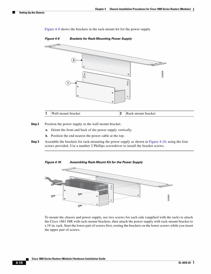
Chapter 4 Chassis Installation Procedures for Cisco 1800 Series Routers (Modular) Setting Up the Chassis
Figure 4-9 shows the brackets in the rack-mount kit for the power supply.
Figure 4-9 Brackets for Rack-Mounting Power Supply
Step 2 Position the power supply in the wall-mount bracket.
a. Orient the front and back of the power supply vertically.
b. Position the end nearest the power cable at the top.
Step 3 Assemble the brackets for rack-mounting the power supply as shown in Figure 4-10, using the four screws provided. Use a number 2 Phillips screwdriver to install the bracket screws.
Figure 4-10 Assembling Rack-Mount Kit for the Power Supply
To mount the chassis and power supply, use two screws for each side (supplied with the rack) to attach the Cisco 1861 ISR with rack-mount brackets, then attach the power supply with rack-mount bracket to a 19-in. rack. Start the lower pair of screws first, resting the brackets on the lower screws while you insert the upper pair of screws.
1 Wall-mount bracket 2 Rack-mount bracket
2426
59
1
2
2426
61
4-10Cisco 1800 Series Routers (Modular) Hardware Installation Guide
OL-5876-03
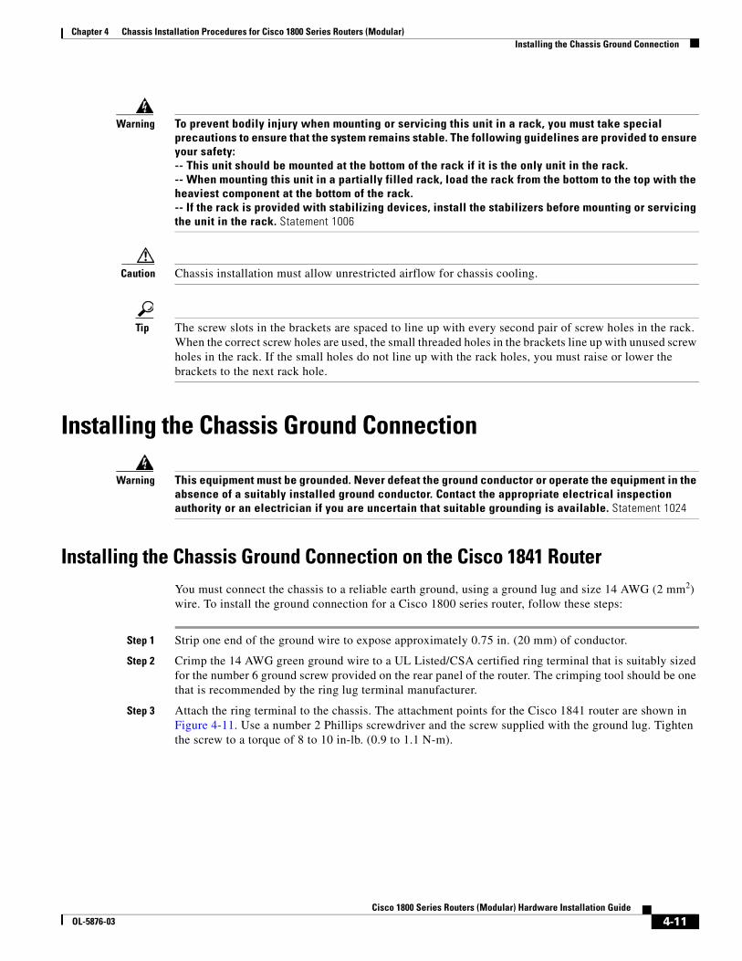
Chapter 4 Chassis Installation Procedures for Cisco 1800 Series Routers (Modular) Installing the Chassis Ground Connection
Warning To prevent bodily injury when mounting or servicing this unit in a rack, you must take special precautions to ensure that the system remains stable. The following guidelines are provided to ensure your safety: -- This unit should be mounted at the bottom of the rack if it is the only unit in the rack. -- When mounting this unit in a partially filled rack, load the rack from the bottom to the top with the heaviest component at the bottom of the rack. -- If the rack is provided with stabilizing devices, install the stabilizers before mounting or servicing the unit in the rack. Statement 1006
Caution Chassis installation must allow unrestricted airflow for chassis cooling.
Tip The screw slots in the brackets are spaced to line up with every second pair of screw holes in the rack. When the correct screw holes are used, the small threaded holes in the brackets line up with unused screw holes in the rack. If the small holes do not line up with the rack holes, you must raise or lower the brackets to the next rack hole.
Installing the Chassis Ground Connection
Warning This equipment must be grounded. Never defeat the ground conductor or operate the equipment in the absence of a suitably installed ground conductor. Contact the appropriate electrical inspection authority or an electrician if you are uncertain that suitable grounding is available. Statement 1024
Installing the Chassis Ground Connection on the Cisco 1841 RouterYou must connect the chassis to a reliable earth ground, using a ground lug and size 14 AWG (2 mm2) wire. To install the ground connection for a Cisco 1800 series router, follow these steps:
Step 1 Strip one end of the ground wire to expose approximately 0.75 in. (20 mm) of conductor.
Step 2 Crimp the 14 AWG green ground wire to a UL Listed/CSA certified ring terminal that is suitably sized for the number 6 ground screw provided on the rear panel of the router. The crimping tool should be one that is recommended by the ring lug terminal manufacturer.
Step 3 Attach the ring terminal to the chassis. The attachment points for the Cisco 1841 router are shown in Figure 4-11. Use a number 2 Phillips screwdriver and the screw supplied with the ground lug. Tighten the screw to a torque of 8 to 10 in-lb. (0.9 to 1.1 N-m).
4-11Cisco 1800 Series Routers (Modular) Hardware Installation Guide
OL-5876-03
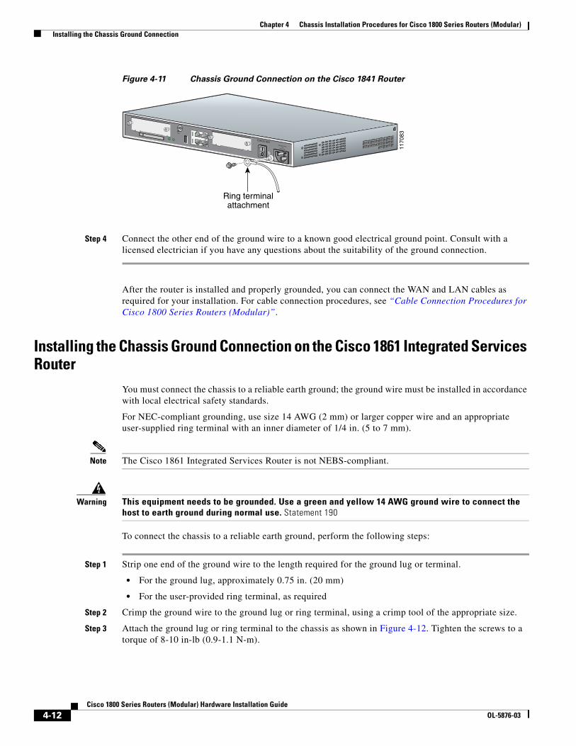
Chapter 4 Chassis Installation Procedures for Cisco 1800 Series Routers (Modular) Installing the Chassis Ground Connection
Figure 4-11 Chassis Ground Connection on the Cisco 1841 Router
Step 4 Connect the other end of the ground wire to a known good electrical ground point. Consult with a licensed electrician if you have any questions about the suitability of the ground connection.
After the router is installed and properly grounded, you can connect the WAN and LAN cables as required for your installation. For cable connection procedures, see “Cable Connection Procedures for Cisco 1800 Series Routers (Modular)”.
Installing the Chassis Ground Connection on the Cisco 1861 Integrated Services Router
You must connect the chassis to a reliable earth ground; the ground wire must be installed in accordance with local electrical safety standards.
For NEC-compliant grounding, use size 14 AWG (2 mm) or larger copper wire and an appropriate user-supplied ring terminal with an inner diameter of 1/4 in. (5 to 7 mm).
Note The Cisco 1861 Integrated Services Router is not NEBS-compliant.
Warning This equipment needs to be grounded. Use a green and yellow 14 AWG ground wire to connect the host to earth ground during normal use. Statement 190
To connect the chassis to a reliable earth ground, perform the following steps:
Step 1 Strip one end of the ground wire to the length required for the ground lug or terminal.
• For the ground lug, approximately 0.75 in. (20 mm)
• For the user-provided ring terminal, as required
Step 2 Crimp the ground wire to the ground lug or ring terminal, using a crimp tool of the appropriate size.
Step 3 Attach the ground lug or ring terminal to the chassis as shown in Figure 4-12. Tighten the screws to a torque of 8-10 in-lb (0.9-1.1 N-m).
1170
83
Ring terminalattachment
CISCO 1841100-240 VAC-1 A
50/60 Hz
4-12Cisco 1800 Series Routers (Modular) Hardware Installation Guide
OL-5876-03
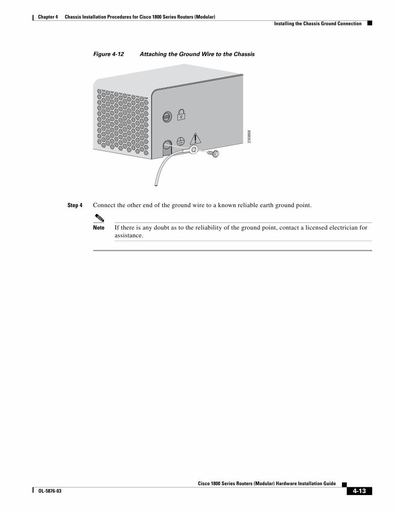
Chapter 4 Chassis Installation Procedures for Cisco 1800 Series Routers (Modular) Installing the Chassis Ground Connection
Figure 4-12 Attaching the Ground Wire to the Chassis
Step 4 Connect the other end of the ground wire to a known reliable earth ground point.
Note If there is any doubt as to the reliability of the ground point, contact a licensed electrician for assistance.
2308
68
4-13Cisco 1800 Series Routers (Modular) Hardware Installation Guide
OL-5876-03

Chapter 4 Chassis Installation Procedures for Cisco 1800 Series Routers (Modular) Installing the Chassis Ground Connection
4-14Cisco 1800 Series Routers (Modular) Hardware Installation Guide
OL-5876-03
Cisco 1800 SeOL-5876-03
C H A P T E R 5
Cable Information and Specifications for Cisco 1800 Series Routers (Modular)This chapter gives cable information and specifications for the console port, auxiliary port, and network ports on your Cisco 1800 series integrated services router (modular). It contains the following sections:
• Console and Auxiliary Port Considerations, page 5-1
• Preparing to Connect to a Network, page 5-2
For cable connection procedures, see “Cable Connection Procedures for Cisco 1800 Series Routers (Modular)”.
Console and Auxiliary Port ConsiderationsThe router includes an asynchronous serial console port and an auxiliary port. The console and auxiliary ports provide access to the router either locally using a console terminal connected to the console port, or remotely, using a modem connected to the auxiliary port. This section provides important cabling information to consider before connecting the router to a console terminal or modem.
The main difference between the console and auxiliary ports is that the auxiliary port supports flow control, whereas the console port does not. Flow control paces the transmission of data between a sending device and a receiving device. Flow control ensures that the receiving device can absorb the data sent to it before the sending device sends more. When the buffers on the receiving device are full, a message is sent to the sending device to suspend transmission until the data in the buffers has been processed. Because the auxiliary port supports flow control, it is ideally suited for use with the high-speed transmissions of a modem. Console terminals send data at slower speeds than modems; therefore, the console port is ideally suited for use with console terminals.
Console Port ConnectionsThe router has an EIA/TIA-232 asynchronous serial console port (RJ-45). Depending on the cable and the adapter used, this port will appear as a data terminal equipment (DTE) or data communications equipment (DCE) device at the end of the cable.
For connection to a PC running terminal emulation software, your router is provided with an RJ-45-to-DB-9 cable.
To connect the router to an ASCII terminal, use the RJ-45-to-DB-9 cable and a DB-9-to-DB-25 adapter (provided).
5-1ries Routers (Modular) Hardware Installation Guide
Chapter 5 Cable Information and Specifications for Cisco 1800 Series Routers (Modular) Preparing to Connect to a Network
The default parameters for the console port are 9600 baud, 8 data bits, no parity, and 1 stop bit. The console port does not support mode control.
For cable and port pinouts, see Cisco Modular Access Router Cable Specifications.
Auxiliary Port ConnectionsThe router has an EIA/TIA-232 asynchronous serial auxiliary port (RJ-45) that supports flow control. Depending on the cable and the adapter used, this port will appear as a DTE or DCE device at the end of the cable.
For connection to a modem, your router is provided with an RJ-45-to-DB-9 cable and a DB-9-to-DB-25 adapter.
For detailed information about connecting devices to the auxiliary port, see the “Connecting to the Auxiliary Port” section on page 6-4 of the “Cable Connection Procedures for Cisco 1800 Series Routers (Modular)” chapter.
For cable and port pinouts, see the Cisco Modular Access Router Cable Specifications document.
Preparing to Connect to a NetworkWhen setting up your router, consider distance limitations and potential electromagnetic interference (EMI) as defined by the applicable local and international regulations.
The following sections describe network connection considerations for several types of network interfaces:
• Ethernet Connections, page 5-2
• Serial Connections, page 5-3
• ISDN BRI Connections, page 5-5
• CSU/DSU Connections, page 5-5
See the following online documents for more information about network connections and interfaces:
• Cisco Interface Cards Installation Guide
• Cisco Modular Access Router Cable Specifications
Warning Only trained and qualified personnel should be allowed to install, replace, or service this equipment. Statement 1030
Ethernet ConnectionsThe IEEE has established Ethernet as standard IEEE 802.3. The Cisco 1800 series Ethernet implementations are as follows:
• 100BASE-T—2-pair Category 5 or unshielded twisted-pair (UTP) straight-through RJ-45 cable. The maximum segment distance is 328 feet (100 meters).
• 10BASE-T—Ethernet on UTP cable. The maximum segment distance is 328 feet (100 meters). UTP cables look like the wiring used for ordinary telephones; however, UTP cables meet certain electrical standards that telephone cables might not meet.
5-2Cisco 1800 Series Routers (Modular) Hardware Installation Guide
OL-5876-03
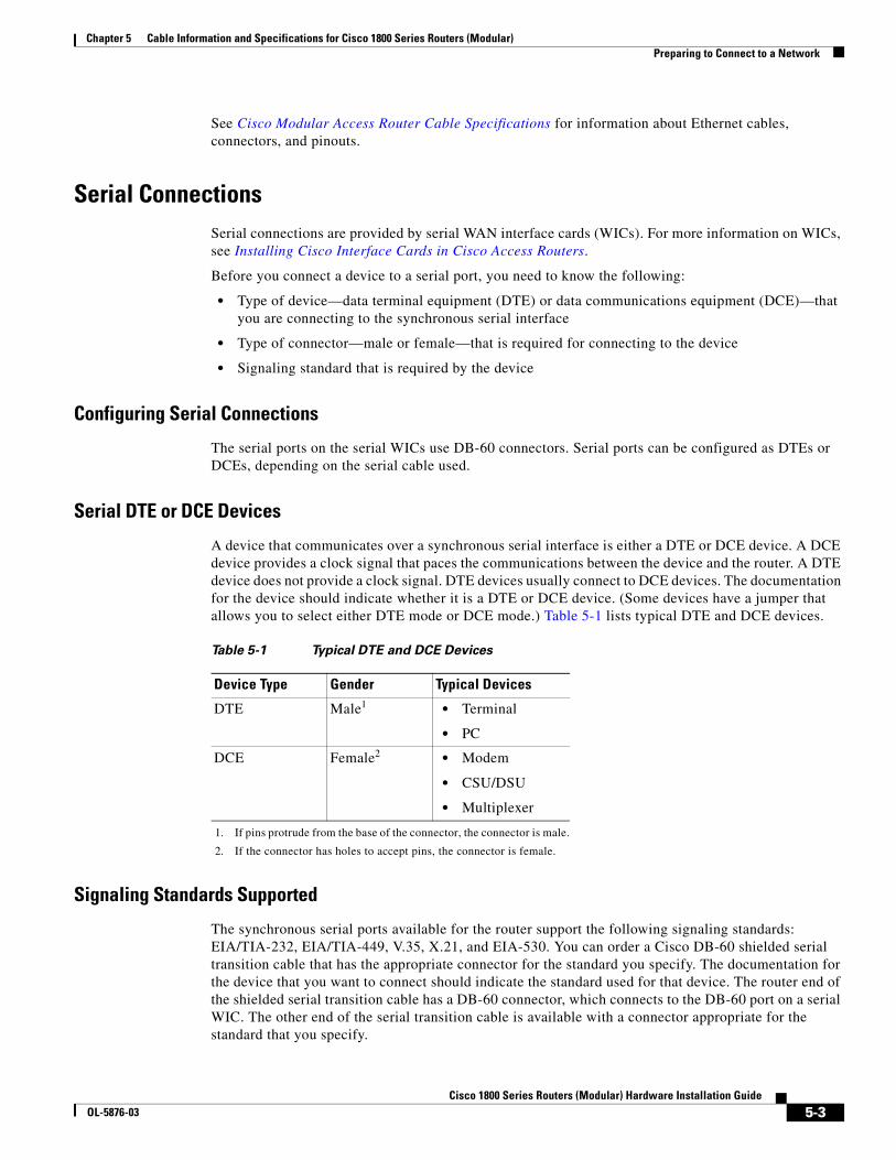
Chapter 5 Cable Information and Specifications for Cisco 1800 Series Routers (Modular) Preparing to Connect to a Network
See Cisco Modular Access Router Cable Specifications for information about Ethernet cables, connectors, and pinouts.
Serial ConnectionsSerial connections are provided by serial WAN interface cards (WICs). For more information on WICs, see Installing Cisco Interface Cards in Cisco Access Routers.
Before you connect a device to a serial port, you need to know the following:
• Type of device—data terminal equipment (DTE) or data communications equipment (DCE)—that you are connecting to the synchronous serial interface
• Type of connector—male or female—that is required for connecting to the device
• Signaling standard that is required by the device
Configuring Serial Connections
The serial ports on the serial WICs use DB-60 connectors. Serial ports can be configured as DTEs or DCEs, depending on the serial cable used.
Serial DTE or DCE Devices
A device that communicates over a synchronous serial interface is either a DTE or DCE device. A DCE device provides a clock signal that paces the communications between the device and the router. A DTE device does not provide a clock signal. DTE devices usually connect to DCE devices. The documentation for the device should indicate whether it is a DTE or DCE device. (Some devices have a jumper that allows you to select either DTE mode or DCE mode.) Table 5-1 lists typical DTE and DCE devices.
Signaling Standards Supported
The synchronous serial ports available for the router support the following signaling standards: EIA/TIA-232, EIA/TIA-449, V.35, X.21, and EIA-530. You can order a Cisco DB-60 shielded serial transition cable that has the appropriate connector for the standard you specify. The documentation for the device that you want to connect should indicate the standard used for that device. The router end of the shielded serial transition cable has a DB-60 connector, which connects to the DB-60 port on a serial WIC. The other end of the serial transition cable is available with a connector appropriate for the standard that you specify.
Table 5-1 Typical DTE and DCE Devices
Device Type Gender Typical Devices
DTE Male1
1. If pins protrude from the base of the connector, the connector is male.
• Terminal
• PC
DCE Female2
2. If the connector has holes to accept pins, the connector is female.
• Modem
• CSU/DSU
• Multiplexer
5-3Cisco 1800 Series Routers (Modular) Hardware Installation Guide
OL-5876-03
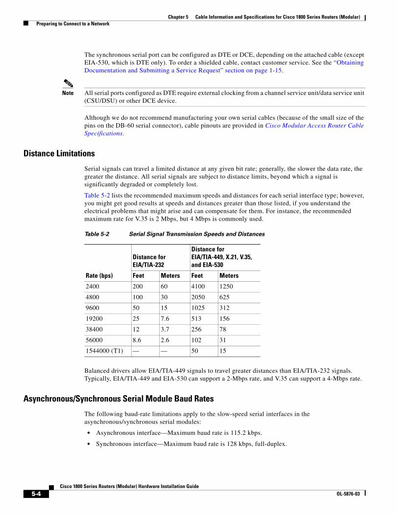
Chapter 5 Cable Information and Specifications for Cisco 1800 Series Routers (Modular) Preparing to Connect to a Network
The synchronous serial port can be configured as DTE or DCE, depending on the attached cable (except EIA-530, which is DTE only). To order a shielded cable, contact customer service. See the “Obtaining Documentation and Submitting a Service Request” section on page 1-15.
Note All serial ports configured as DTE require external clocking from a channel service unit/data service unit (CSU/DSU) or other DCE device.
Although we do not recommend manufacturing your own serial cables (because of the small size of the pins on the DB-60 serial connector), cable pinouts are provided in Cisco Modular Access Router Cable Specifications.
Distance Limitations
Serial signals can travel a limited distance at any given bit rate; generally, the slower the data rate, the greater the distance. All serial signals are subject to distance limits, beyond which a signal is significantly degraded or completely lost.
Table 5-2 lists the recommended maximum speeds and distances for each serial interface type; however, you might get good results at speeds and distances greater than those listed, if you understand the electrical problems that might arise and can compensate for them. For instance, the recommended maximum rate for V.35 is 2 Mbps, but 4 Mbps is commonly used.
Balanced drivers allow EIA/TIA-449 signals to travel greater distances than EIA/TIA-232 signals. Typically, EIA/TIA-449 and EIA-530 can support a 2-Mbps rate, and V.35 can support a 4-Mbps rate.
Asynchronous/Synchronous Serial Module Baud Rates
The following baud-rate limitations apply to the slow-speed serial interfaces in the asynchronous/synchronous serial modules:
• Asynchronous interface—Maximum baud rate is 115.2 kbps.
• Synchronous interface—Maximum baud rate is 128 kbps, full-duplex.
Table 5-2 Serial Signal Transmission Speeds and Distances
Distance for EIA/TIA-232
Distance for EIA/TIA-449, X.21, V.35, and EIA-530
Rate (bps) Feet Meters Feet Meters
2400 200 60 4100 1250
4800 100 30 2050 625
9600 50 15 1025 312
19200 25 7.6 513 156
38400 12 3.7 256 78
56000 8.6 2.6 102 31
1544000 (T1) — — 50 15
5-4Cisco 1800 Series Routers (Modular) Hardware Installation Guide
OL-5876-03
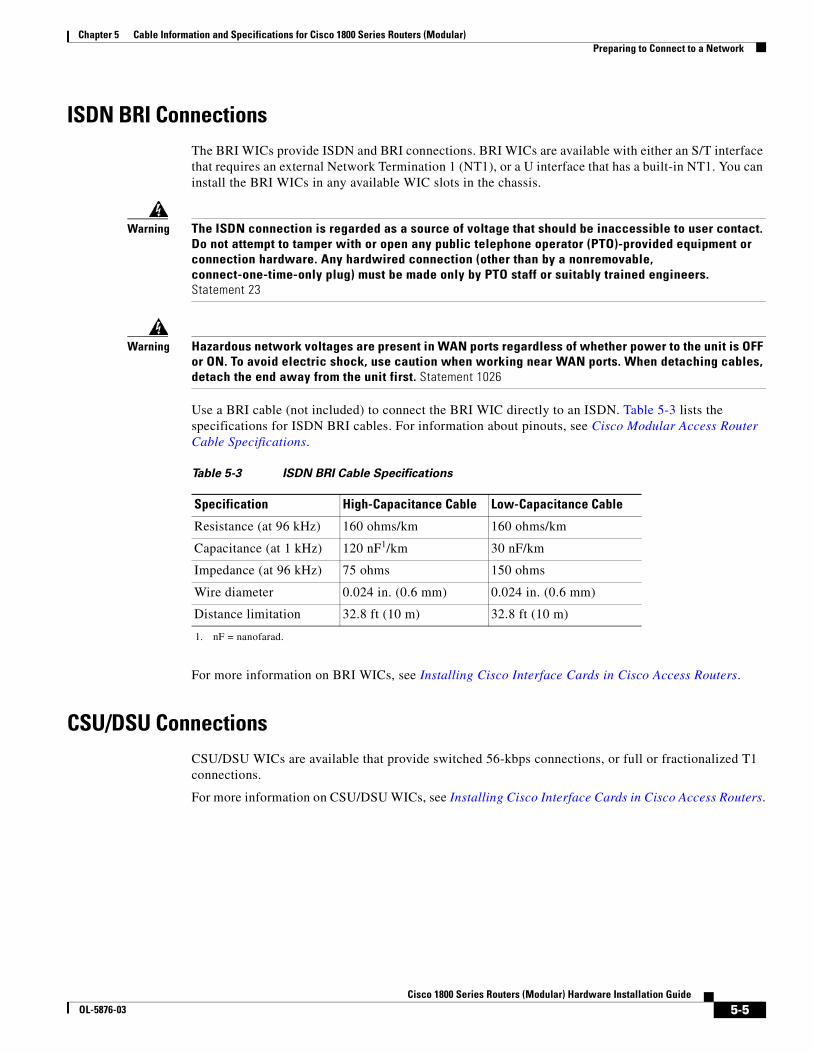
Chapter 5 Cable Information and Specifications for Cisco 1800 Series Routers (Modular) Preparing to Connect to a Network
ISDN BRI ConnectionsThe BRI WICs provide ISDN and BRI connections. BRI WICs are available with either an S/T interface that requires an external Network Termination 1 (NT1), or a U interface that has a built-in NT1. You can install the BRI WICs in any available WIC slots in the chassis.
Warning The ISDN connection is regarded as a source of voltage that should be inaccessible to user contact. Do not attempt to tamper with or open any public telephone operator (PTO)-provided equipment or connection hardware. Any hardwired connection (other than by a nonremovable, connect-one-time-only plug) must be made only by PTO staff or suitably trained engineers. Statement 23
Warning Hazardous network voltages are present in WAN ports regardless of whether power to the unit is OFF or ON. To avoid electric shock, use caution when working near WAN ports. When detaching cables, detach the end away from the unit first. Statement 1026
Use a BRI cable (not included) to connect the BRI WIC directly to an ISDN. Table 5-3 lists the specifications for ISDN BRI cables. For information about pinouts, see Cisco Modular Access Router Cable Specifications.
For more information on BRI WICs, see Installing Cisco Interface Cards in Cisco Access Routers.
CSU/DSU ConnectionsCSU/DSU WICs are available that provide switched 56-kbps connections, or full or fractionalized T1 connections.
For more information on CSU/DSU WICs, see Installing Cisco Interface Cards in Cisco Access Routers.
Table 5-3 ISDN BRI Cable Specifications
Specification High-Capacitance Cable Low-Capacitance Cable
Resistance (at 96 kHz) 160 ohms/km 160 ohms/km
Capacitance (at 1 kHz) 120 nF1/km
1. nF = nanofarad.
30 nF/km
Impedance (at 96 kHz) 75 ohms 150 ohms
Wire diameter 0.024 in. (0.6 mm) 0.024 in. (0.6 mm)
Distance limitation 32.8 ft (10 m) 32.8 ft (10 m)
5-5Cisco 1800 Series Routers (Modular) Hardware Installation Guide
OL-5876-03

Chapter 5 Cable Information and Specifications for Cisco 1800 Series Routers (Modular) Preparing to Connect to a Network
5-6Cisco 1800 Series Routers (Modular) Hardware Installation Guide
OL-5876-03
Cisco 1800 SeOL-5876-03
C H A P T E R 6
Cable Connection Procedures for Cisco 1800 Series Routers (Modular)This chapter describes how to connect your Cisco 1800 series integrated services router (modular) to a power source and to networks and external devices. It includes the following sections:
• Power Connections, page 6-1
• Connecting WAN and LAN Cables, page 6-2
• Connecting to a Console Terminal or Modem, page 6-3
For cable information and specifications, see the “Cable Information and Specifications for Cisco 1800 Series Routers (Modular)” document.
Note To see translations of the warnings that appear in this publication, see the Regulatory Compliance and Safety Information for Cisco 1840 Routers.
Power Connections
Warning Read the installation instructions before connecting the system to the power source. Statement 1004.
Note The installation must comply with all required electrical codes applicable at the installation site.
Connect your router to a 15 A, 120 VAC (10 A, 240 VAC) circuit with overcurrent protection.
Note The input voltage tolerance limits for AC power are 85 and 264 VAC.
Warning This product relies on the building’s installation for short-circuit (overcurrent) protection. Ensure that the protective device is rated not greater than: 15A, 120VAC (10A, 240VAC). Statement 1005
6-1ries Routers (Modular) Hardware Installation Guide
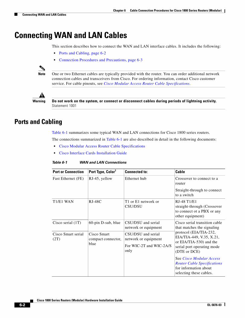
Chapter 6 Cable Connection Procedures for Cisco 1800 Series Routers (Modular) Connecting WAN and LAN Cables
Connecting WAN and LAN CablesThis section describes how to connect the WAN and LAN interface cables. It includes the following:
• Ports and Cabling, page 6-2
• Connection Procedures and Precautions, page 6-3
Note One or two Ethernet cables are typically provided with the router. You can order additional network connection cables and transceivers from Cisco. For ordering information, contact Cisco customer service. For cable pinouts, see Cisco Modular Access Router Cable Specifications.
Warning Do not work on the system, or connect or disconnect cables during periods of lightning activity. Statement 1001
Ports and CablingTable 6-1 summarizes some typical WAN and LAN connections for Cisco 1800 series routers.
The connections summarized in Table 6-1 are also described in detail in the following documents:
• Cisco Modular Access Router Cable Specifications
• Cisco Interface Cards Installation Guide
Table 6-1 WAN and LAN Connections
Port or Connection Port Type, Color1 Connected to: Cable
Fast Ethernet (FE) RJ-45, yellow Ethernet hub Crossover to connect to a router
Straight-through to connect to a switch
T1/E1 WAN RJ-48C T1 or E1 network or CSU/DSU
RJ-48 T1/E1 straight-through (Crossover to connect ot a PBX or any other equipment)
Cisco serial (1T) 60-pin D-sub, blue CSU/DSU and serial network or equipment
Cisco serial transition cable that matches the signaling protocol (EIA/TIA-232, EIA/TIA-449, V.35, X.21, or EIA/TIA-530) and the serial port operating mode (DTE or DCE)
See Cisco Modular Access Router Cable Specifications for information about selecting these cables.
Cisco Smart serial (2T)
Cisco Smart compact connector, blue
CSU/DSU and serial network or equipment
For WIC-2T and WIC-2A/S only
6-2Cisco 1800 Series Routers (Modular) Hardware Installation Guide
OL-5876-03
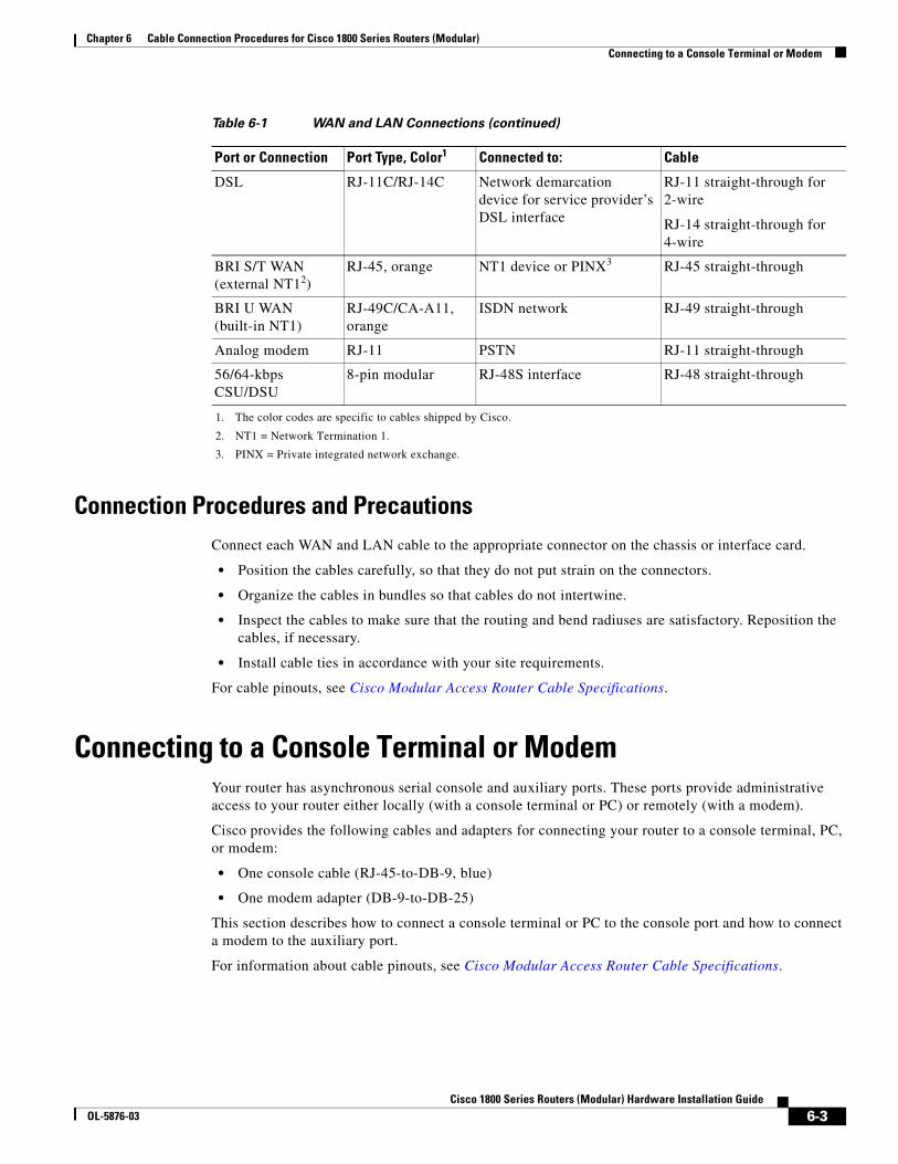
Chapter 6 Cable Connection Procedures for Cisco 1800 Series Routers (Modular) Connecting to a Console Terminal or Modem
Connection Procedures and PrecautionsConnect each WAN and LAN cable to the appropriate connector on the chassis or interface card.
• Position the cables carefully, so that they do not put strain on the connectors.
• Organize the cables in bundles so that cables do not intertwine.
• Inspect the cables to make sure that the routing and bend radiuses are satisfactory. Reposition the cables, if necessary.
• Install cable ties in accordance with your site requirements.
For cable pinouts, see Cisco Modular Access Router Cable Specifications.
Connecting to a Console Terminal or ModemYour router has asynchronous serial console and auxiliary ports. These ports provide administrative access to your router either locally (with a console terminal or PC) or remotely (with a modem).
Cisco provides the following cables and adapters for connecting your router to a console terminal, PC, or modem:
• One console cable (RJ-45-to-DB-9, blue)
• One modem adapter (DB-9-to-DB-25)
This section describes how to connect a console terminal or PC to the console port and how to connect a modem to the auxiliary port.
For information about cable pinouts, see Cisco Modular Access Router Cable Specifications.
DSL RJ-11C/RJ-14C Network demarcation device for service provider’s DSL interface
RJ-11 straight-through for 2-wire
RJ-14 straight-through for 4-wire
BRI S/T WAN (external NT12)
RJ-45, orange NT1 device or PINX3 RJ-45 straight-through
BRI U WAN (built-in NT1)
RJ-49C/CA-A11, orange
ISDN network RJ-49 straight-through
Analog modem RJ-11 PSTN RJ-11 straight-through
56/64-kbps CSU/DSU
8-pin modular RJ-48S interface RJ-48 straight-through
1. The color codes are specific to cables shipped by Cisco.
2. NT1 = Network Termination 1.
3. PINX = Private integrated network exchange.
Table 6-1 WAN and LAN Connections (continued)
Port or Connection Port Type, Color1 Connected to: Cable
6-3Cisco 1800 Series Routers (Modular) Hardware Installation Guide
OL-5876-03
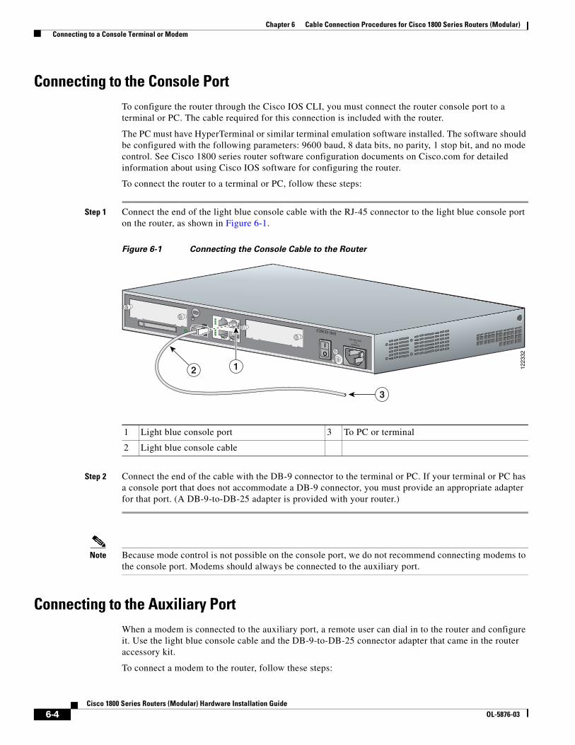
Chapter 6 Cable Connection Procedures for Cisco 1800 Series Routers (Modular) Connecting to a Console Terminal or Modem
Connecting to the Console PortTo configure the router through the Cisco IOS CLI, you must connect the router console port to a terminal or PC. The cable required for this connection is included with the router.
The PC must have HyperTerminal or similar terminal emulation software installed. The software should be configured with the following parameters: 9600 baud, 8 data bits, no parity, 1 stop bit, and no mode control. See Cisco 1800 series router software configuration documents on Cisco.com for detailed information about using Cisco IOS software for configuring the router.
To connect the router to a terminal or PC, follow these steps:
Step 1 Connect the end of the light blue console cable with the RJ-45 connector to the light blue console port on the router, as shown in Figure 6-1.
Figure 6-1 Connecting the Console Cable to the Router
Step 2 Connect the end of the cable with the DB-9 connector to the terminal or PC. If your terminal or PC has a console port that does not accommodate a DB-9 connector, you must provide an appropriate adapter for that port. (A DB-9-to-DB-25 adapter is provided with your router.)
Note Because mode control is not possible on the console port, we do not recommend connecting modems to the console port. Modems should always be connected to the auxiliary port.
Connecting to the Auxiliary PortWhen a modem is connected to the auxiliary port, a remote user can dial in to the router and configure it. Use the light blue console cable and the DB-9-to-DB-25 connector adapter that came in the router accessory kit.
To connect a modem to the router, follow these steps:
1 Light blue console port 3 To PC or terminal
2 Light blue console cable
1223
32
12
3
CISCO 1841100-240 VAC-1 A
50/60 Hz
6-4Cisco 1800 Series Routers (Modular) Hardware Installation Guide
OL-5876-03
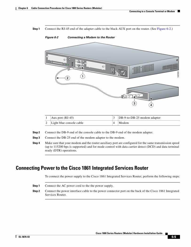
Chapter 6 Cable Connection Procedures for Cisco 1800 Series Routers (Modular) Connecting to a Console Terminal or Modem
Step 1 Connect the RJ-45 end of the adapter cable to the black AUX port on the router. (See Figure 6-2.)
Figure 6-2 Connecting a Modem to the Router
Step 2 Connect the DB-9 end of the console cable to the DB-9 end of the modem adapter.
Step 3 Connect the DB-25 end of the modem adapter to the modem.
Step 4 Make sure that your modem and the router auxiliary port are configured for the same transmission speed (up to 115200 bps is supported) and for mode control with data carrier detect (DCD) and data terminal ready (DTR) operations.
Connecting Power to the Cisco 1861 Integrated Services RouterTo connect the power supply to the Cisco 1861 Integrated Services Router, perform the following steps:
Step 1 Connect the AC power cord to the the power supply.
Step 2 Connect the power interface cable to the power connector port on the back of the Cisco 1861 Integrated Services Router.
1 Aux port (RJ-45) 3 DB-9-to-DB-25 modem adapter
2 Light blue console cable 4 Modem
1223
33
12
3 4
CISCO 1841100-240 VAC-1 A
50/60 Hz
6-5Cisco 1800 Series Routers (Modular) Hardware Installation Guide
OL-5876-03

Chapter 6 Cable Connection Procedures for Cisco 1800 Series Routers (Modular) Connecting to a Console Terminal or Modem
6-6Cisco 1800 Series Routers (Modular) Hardware Installation Guide
OL-5876-03
Cisco 1800 SeOL-5876-03
C H A P T E R 7
Power-Up Procedures for Cisco 1800 Series Routers (Modular)This chapter describes how to power up Cisco 1800 series integrated services routers (modular) and perform an initial configuration to provide network access. It includes the following sections:
Powering Up Cisco 1800 Series Routers, page 7-1
Verifying the LED Indicators on the 1841 Router, page 7-4
Verifying the Hardware Configuration, page 7-5
Initial Configuration of the Router, page 7-5
Software Components of the Cisco 1861 Integrated Services Router, page 7-7
Note To see translations of the warnings that appear in this publication, see the Regulatory Compliance and Safety Information for Cisco 1840 Routers.
Note The Cisco 1861 Integrated Services Router supports a maximum of 12 user licenses based on different models.
Powering Up Cisco 1800 Series Routers
Warning The plug-socket combination must be accessible at all times because it serves as the main disconnecting device. Statement 1019
Warning Blank faceplates and cover panels serve three important functions: they prevent exposure to hazardous voltages and currents inside the chassis; they contain electromagnetic interference (EMI) that might disrupt other equipment; and they direct the flow of cooling air through the chassis. Do not operate the system unless all cards, faceplates, front covers, and rear covers are in place. Statement 1029.
Caution To ensure adequate cooling, never operate the router unless the unit is completely closed.
7-1ries Routers (Modular) Hardware Installation Guide
Chapter 7 Power-Up Procedures for Cisco 1800 Series Routers (Modular) Powering Up Cisco 1800 Series Routers
This section covers the following topics:
• Checklist for Power Up, page 7-2
• LED Indicators, page 7-2
• Power-Up Procedure, page 7-2
Checklist for Power UpYou may power up the Cisco router if the following steps have been completed:
• Mount and ground the chassis securely.
• Connect the power and interface cables.
• Make sure that the external CompactFlash memory card is properly seated into its slot. For installation instructions, see “Installing and Replacing CompactFlash Memory Cards on Cisco 1800 Series Routers (Modular)”.
• Connect a PC to the router’s console port.
• Start HyperTerminal or a similar terminal emulation program on your PC. Select the appropriate PC COM port. Set the terminal emulation program configuration for 9600 baud, 8 data bits, 1 stop bit, no flow control, and no parity.
Note For initial power up, we recommend a direct console connection. After the intial configuration is completed, a remote modem connection can be used for router management.
Caution To ensure adequate cooling, never operate the router unless the cover and all modules and cover plates are installed.
Caution To prevent damage to the ejector mechanism, the ejector button next to the CompactFlash memory card must remain fully seated when not being used to eject a CompactFlash memory card.
LED IndicatorsThe meanings of the LED indicators for Cisco 1800 series routers are summarized in Table 2-5. For more detailed information about the LEDs, see Chapter 8, “Troubleshooting Cisco 1800 Series Routers (Modular).”
Power-Up ProcedureTo power up your Cisco router and verify that it completes its initialization and self-test, follow this procedure. When you have completed the procedure you may begin configuring the router.
7-2Cisco 1800 Series Routers (Modular) Hardware Installation Guide
OL-5876-03
Chapter 7 Power-Up Procedures for Cisco 1800 Series Routers (Modular) Powering Up Cisco 1800 Series Routers
If you encounter problems when you power up the router, see Chapter 8, “Troubleshooting Cisco 1800 Series Routers (Modular).” For information about the ROM monitor and the bootstrap program, see the “Using the ROM Monitor” section of the Cisco 1800 Series Router Software Configuration. For information about the configuration register, see the“Changing the Configuration Register Settings” section of Cisco 1800 Series Router Software Configuration.
Note To view the boot sequence through a terminal session, you must have a console connection to the Cisco router before the router powers up.
To power up the router, perform the following steps:
Step 1 Make sure that your PC is powered up and connected as described in the “Checklist for Power Up” section on page 7-2.
Step 2 Move the power switch to the ON position.
The following indications appear:
• The green SYS PWR LED on the front of the chassis comes on.
• The fan operates.
The LEDs on the chassis come on (although not necessarily at the same time), and some LEDs may go off again. The actual LED activity depends on your installation.
If you encounter problems when you power up the router, see “Troubleshooting Cisco 1800 Series Routers (Modular)”
Startup messages appear in your terminal emulation program window.
Caution Do not press any keys on the keyboard until the messages stop. Any keys pressed during this time are interpreted as the first command typed when the messages stop, which might cause the router to power off and start over. It takes a few minutes for the messages to stop.
The startup messages vary, depending on the software installed on your router.
• If the startup messages end with the following lines, you know that the Cisco Router and Security Device Manager (SDM) software is installed on the router.
yourname con0 is now available
Press RETURN to get started!
For instructions on configuring your router by using SDM, see Cisco Router and Security Device Manager (SDM) Quick Start Guide.
Note Because SDM is installed on your router by default, we recommend using SDM to perform the initial configuration.
• If the startup messages end with the following lines, the router is ready for initial configuration using the setup facility (system configuration dialog) or the command-line interface (CLI). Enter yes to continue with the setup facility; enter no to continue with the CLI.
7-3Cisco 1800 Series Routers (Modular) Hardware Installation Guide
OL-5876-03
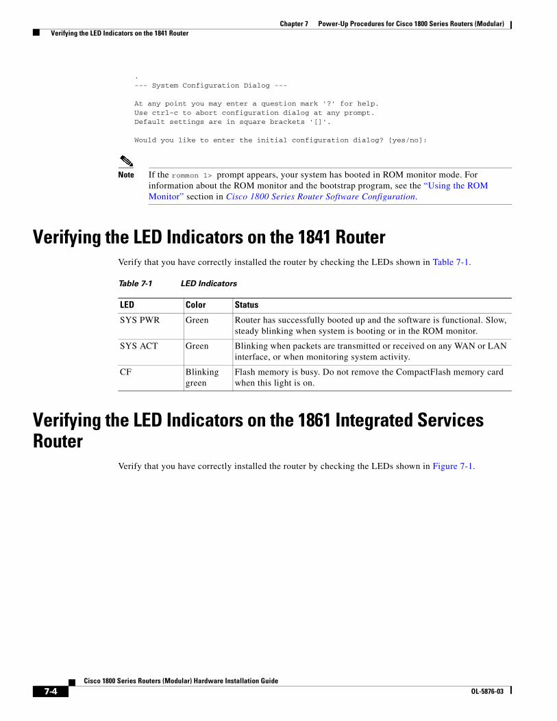
Chapter 7 Power-Up Procedures for Cisco 1800 Series Routers (Modular) Verifying the LED Indicators on the 1841 Router
.--- System Configuration Dialog ---
At any point you may enter a question mark '?' for help.Use ctrl-c to abort configuration dialog at any prompt.Default settings are in square brackets '[]'.
Would you like to enter the initial configuration dialog? [yes/no]:
Note If the rommon 1> prompt appears, your system has booted in ROM monitor mode. For information about the ROM monitor and the bootstrap program, see the “Using the ROM Monitor” section in Cisco 1800 Series Router Software Configuration.
Verifying the LED Indicators on the 1841 RouterVerify that you have correctly installed the router by checking the LEDs shown in Table 7-1.
Verifying the LED Indicators on the 1861 Integrated Services Router
Verify that you have correctly installed the router by checking the LEDs shown in Figure 7-1.
Table 7-1 LED Indicators
LED Color Status
SYS PWR Green Router has successfully booted up and the software is functional. Slow, steady blinking when system is booting or in the ROM monitor.
SYS ACT Green Blinking when packets are transmitted or received on any WAN or LAN interface, or when monitoring system activity.
CF Blinking green
Flash memory is busy. Do not remove the CompactFlash memory card when this light is on.
7-4Cisco 1800 Series Routers (Modular) Hardware Installation Guide
OL-5876-03
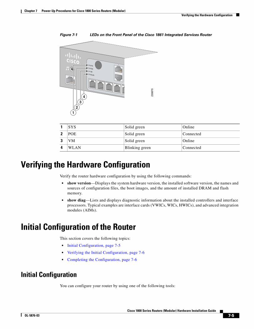
Chapter 7 Power-Up Procedures for Cisco 1800 Series Routers (Modular) Verifying the Hardware Configuration
Figure 7-1 LEDs on the Front Panel of the Cisco 1861 Integrated Services Router
Verifying the Hardware ConfigurationVerify the router hardware configuration by using the following commands:
• show version—Displays the system hardware version, the installed software version, the names and sources of configuration files, the boot images, and the amount of installed DRAM and flash memory.
• show diag—Lists and displays diagnostic information about the installed controllers and interface processors. Typical examples are interface cards (VWICs, WICs, HWICs), and advanced integration modules (AIMs).
Initial Configuration of the RouterThis section covers the following topics:
• Initial Configuration, page 7-5
• Verifying the Initial Configuration, page 7-6
• Completing the Configuration, page 7-6
Initial ConfigurationYou can configure your router by using one of the following tools:
1 SYS Solid green Online
2 POE Solid green Connected
3 VM Solid green Online
4 WLAN Blinking green Connected23
0870
1SYS
POE
VM
WLAN
43
21
7-5Cisco 1800 Series Routers (Modular) Hardware Installation Guide
OL-5876-03
Chapter 7 Power-Up Procedures for Cisco 1800 Series Routers (Modular) Initial Configuration of the Router
• Cisco Router and Security Device Manager—See the “Cisco Router and Security Device Manager” section on page 7-6
• Setup command facility—See the “Initial Configuration Using the Setup Command Facility” section in the Cisco 1800 Series Integrated Services Routers (Modular) Quick Start Guide.
• Command-line interface (CLI)—See the “Initial Configuration Using Cisco CLI—Manual Configuration” section in the Cisco 1800 Series Integrated Services Routers (Modular) Quick Start Guide.
Cisco Router and Security Device Manager
If the Cisco Router and Security Device Manager (SDM) has been installed on your router, the following messages appear at the end of the startup sequence:
yourname con0 is now available
Press RETURN to get started.
For instructions on configuring your router by using SDM, see the Cisco Router and Security Device Manager (SDM) Quick Start Guide. To use SDM, you can download the latest version of SDM and instructions for installing it on your router:
http://www.cisco.com/pcgi-bin/tablebuild.pl/sdm
To obtain the SDM quick start guide, SDM release notes, and other SDM documentation, go to www.cisco.com/go/sdm.
Verifying the Initial ConfigurationVerify that the new interfaces are operating correctly by performing the following tests:
• Enter the show interfaces command to verify that the interfaces are operating correctly and that the interfaces and line protocol are in the correct state—up or down.
• Enter the show ip interface brief command to display a summary status of the interfaces configured for IP.
• Enter the show configuration command to verify that you configured the correct hostname and password.
When you have completed and verified the initial configuration, your Cisco router is ready to be configured for specific functions. See the “Completing the Configuration” section on page 7-6 for information about locating documentation for advanced configuration procedures.
Completing the ConfigurationWhen you have completed and verified the initial configuration, your Cisco router is ready to be configured for specific functions. For advanced configuration procedures, use either SDM or the CLI.
For configuration procedures using SDM, see Cisco Router and Security Device Manager (SDM) Quick Start Guide.
For configuration procedures using the CLI, see Cisco 1800 Series Router Software Configuration. The software configuration documents include information about the following topics:
• Basic software configuration
7-6Cisco 1800 Series Routers (Modular) Hardware Installation Guide
OL-5876-03
Chapter 7 Power-Up Procedures for Cisco 1800 Series Routers (Modular) Powering up the Cisco 1861 Integrated Services Router
• Feature documentation
• Troubleshooting and maintenance
• Cisco 1800 series cards and modules
Powering up the Cisco 1861 Integrated Services RouterTo power up the Cisco 1861 Integrated Services Router, perform the following steps:
Step 1 Verify that the AC power cord is connected to the power supply.
Step 2 Power up the power supply and the Cisco 1861 ISR, by connecting the power cord plug to a grounded AC outlet.
Note There is no external Power On/Off switch on the power supply.
Step 3 Verify the LED indicators on the front panel of the Cisco 1861 Integrated Services Router, as required. See Figure 7-1.
Software Components of the Cisco 1861 Integrated Services Router
The Cisco 1861 Integrated Services Router is shipped with a factory-installed software configuration for a basic IP telephony system that enables phone users to make and receive calls using the preconfigured numbers on their IP phones within minutes after connecting the Cisco 1861 Integrated Services Router to the Ethernet and their IP phones to the platform. Table 7-2 summarizes the software components of the Cisco 1861 Integrated Services Router.
Table 7-2 Cisco 1861 Integrated Services Router Software Components
Software Component Description Benefits
Cisco Unified Communications Manager Express (Cisco Unified CME)
Entry-level call processing system that provides a wide range of IP telephony features for small to medium-sized business customers and autonomous small enterprise branch offices.
All files and configurations for IP phones are stored internally on the Cisco 1861 Integrated Services Router for a cost-effective, highly reliable, IP communications solution.
Cisco Unity Express Provides voice mail and automated attendant services specifically designed for the small and medium-sized branch office environment.
Users can easily and conveniently manage their voice messages and greetings with intuitive telephone prompts and a straightforward web-based GUI that allows simple administration
7-7Cisco 1800 Series Routers (Modular) Hardware Installation Guide
OL-5876-03
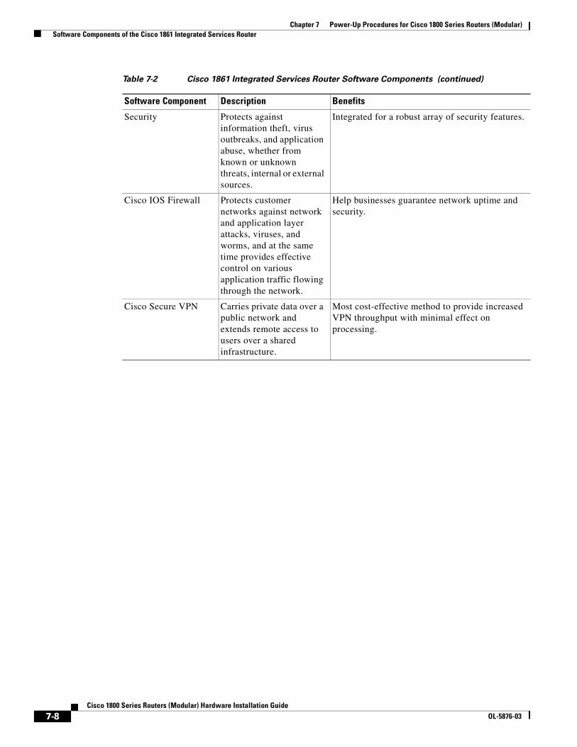
Chapter 7 Power-Up Procedures for Cisco 1800 Series Routers (Modular) Software Components of the Cisco 1861 Integrated Services Router
Security Protects against information theft, virus outbreaks, and application abuse, whether from known or unknown threats, internal or external sources.
Integrated for a robust array of security features.
Cisco IOS Firewall Protects customer networks against network and application layer attacks, viruses, and worms, and at the same time provides effective control on various application traffic flowing through the network.
Help businesses guarantee network uptime and security.
Cisco Secure VPN Carries private data over a public network and extends remote access to users over a shared infrastructure.
Most cost-effective method to provide increased VPN throughput with minimal effect on processing.
Table 7-2 Cisco 1861 Integrated Services Router Software Components (continued)
Software Component Description Benefits
7-8Cisco 1800 Series Routers (Modular) Hardware Installation Guide
OL-5876-03
Cisco 1800 SeOL-5876-03
C H A P T E R 8
Troubleshooting Cisco 1800 Series Routers (Modular)If you encounter problems with your Cisco 1800 series integrated services router (ISR) (modular), the information in this chapter can help you isolate problems in the router or eliminate the router as the source of the problem.
This chapter contains the following sections:
• Problem Solving, page 8-1
• Reading LEDs, page 8-4
• System Messages, page 8-5
• Recovering a Lost Password, page 8-6
• More Troubleshooting Help, page 8-6
Note To troubleshoot interface cards, see Overview of Cisco Interface Cards for Cisco Access Routers.
If you cannot locate the source of the problem, contact a Cisco customer service representative for information on how to proceed. For technical support information, see the “Obtaining Documentation and Submitting a Service Request” section on page 1-15. Before you call, have the following information ready:
• Chassis type and serial number
• Maintenance agreement or warranty information
• Type of software and version number
• Date you received the router
• Brief description of the problem
• Brief explanation of the steps you have taken to isolate the problem
Problem SolvingThe key to problem solving is to isolate the problem to a specific subsystem by comparing what the router is doing to what it should be doing.
The LEDs on the router aid you in determining router performance and operation. The LEDs are described in the “Reading LEDs” section on page 8-4.
8-1ries Routers (Modular) Hardware Installation Guide
Chapter 8 Troubleshooting Cisco 1800 Series Routers (Modular) Problem Solving
When solving problems, consider the following router subsystems:
• Power and cooling systems—External power source, power cable, router power supply, circuit breaker, and router fan. Also check for inadequate ventilation or air circulation.
• Interface cards—LEDs on the interface cards help identify a failure.
• Cables—External cables that connect the router to the network.
Troubleshooting the Power and Cooling SystemsBoth the system LED and the fans can help you troubleshoot a power problem. Check the following items to help isolate the problem:
Normal Indications
With the power switch on, the normal indications are:
• SYS PWR LED on green and continuous
• Fan operating
Fault Indications
Check the following symptoms to locate or eliminate faults in the power and cooling systems:
• With the power switch on, is the SYS PWR LED on?
– If the LED is green and continuous, the router is receiving power and is functional.
– If the LED is off, check the power source and power cable.
• With the power switch on and the SYS PWR LED on and green, does the fan operate?
– If no, check the fan.
– If yes, the power system is functioning.
• With the power switch on and the SYS PWR LED off, does the fan operate?
– If yes, the router is receiving power. The fan is connected directly to the DC outputs of the power supply.
– If no, check the power source and power cable.
• Does the router shut down after being on a short time?
– Check for an environmentally induced shutdown. See the next section, “Environmental Reporting Features, page 8-3.”
– Check the environmental site requirements in the “General Site Requirements” section on page 3-3.
– Check for a power supply failure by inspecting the SYS PWR LED on the front panel. If it is green, the power supply is functional.
• Router partially boots, but LEDs do not go on.
– Check for a power supply failure by inspecting the SYS PWR LED on the front panel of the router. If the SYS PWR LED is blinking or continuously green, the power supply is functional.
– If the SYS PWR LED is not on, see “Cisco One-Year Limited Hardware Warranty Terms” section on page 1-14.
8-2Cisco 1800 Series Routers (Modular) Hardware Installation Guide
OL-5876-03
Chapter 8 Troubleshooting Cisco 1800 Series Routers (Modular) Problem Solving
Environmental Reporting Features
If the router is operating at an abnormally high temperature, consider the following causes:
• Fan failure
• Air conditioner failure in the room
• Air blockage to cooling vents
Take steps to correct the problem. See the “Site Environment” section on page 3-4.
Troubleshooting Cables, Connections, and Interface CardsNetwork problems can be caused by cables, cable connections, or interface cards, or by external devices such as a modem, transceiver, hub, wall jack, WAN interface, or terminal. Check for the following symptoms to help isolate the problem.
• Card is not recognized by the router.
– Make sure that the card is firmly seated in its slot.
– Check the LEDs on the card. Each card has its own set of LEDs.
– Make sure that you have a version of Cisco IOS software that supports the card.
• Card is recognized, but interface ports do not initialize.
– Make sure that the card is firmly seated in its slot.
– Check external cable connections.
– Make sure that you have a version of Cisco IOS software that supports the card. Check the software requirements for the affected card, which can be found in the configuration note for the card.
• Router does not boot properly, or constantly or intermittently reboots.
– Make sure that the card is firmly seated in its slot.
– Check the router chassis or software.
• Router boots, but the console screen is frozen.
– Check the external console connection.
– Verify that the parameters for your terminal are set as follows:
(a) The same data rate as configured for the router (9600 baud is the default)
(b) 8 data bits
(c) 1 stop bit
(d) No parity generated or checked
• Router powers on and boots only when a particular card is removed.
– Check the card. See the “Cisco One-Year Limited Hardware Warranty Terms” section on page 1-14 and the “Obtaining Documentation and Submitting a Service Request” section on page 15 of the “Introduction to Cisco 1800 Series Routers (Modular) Hardware Documentation” document for warranty and customer service contact information.
• Router powers on and boots only when a particular cable is disconnected.
8-3Cisco 1800 Series Routers (Modular) Hardware Installation Guide
OL-5876-03
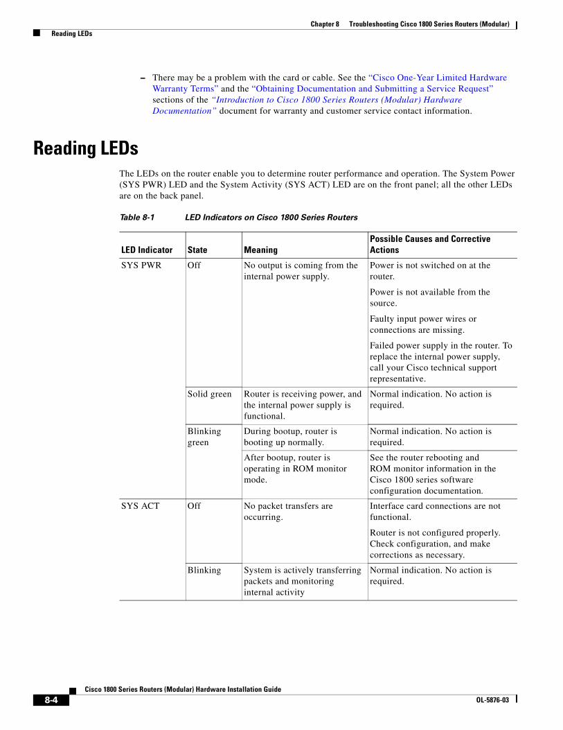
Chapter 8 Troubleshooting Cisco 1800 Series Routers (Modular) Reading LEDs
– There may be a problem with the card or cable. See the “Cisco One-Year Limited Hardware Warranty Terms” and the “Obtaining Documentation and Submitting a Service Request” sections of the “Introduction to Cisco 1800 Series Routers (Modular) Hardware Documentation” document for warranty and customer service contact information.
Reading LEDsThe LEDs on the router enable you to determine router performance and operation. The System Power (SYS PWR) LED and the System Activity (SYS ACT) LED are on the front panel; all the other LEDs are on the back panel.
Table 8-1 LED Indicators on Cisco 1800 Series Routers
LED Indicator State MeaningPossible Causes and Corrective Actions
SYS PWR Off No output is coming from the internal power supply.
Power is not switched on at the router.
Power is not available from the source.
Faulty input power wires or connections are missing.
Failed power supply in the router. To replace the internal power supply, call your Cisco technical support representative.
Solid green Router is receiving power, and the internal power supply is functional.
Normal indication. No action is required.
Blinking green
During bootup, router is booting up normally.
Normal indication. No action is required.
After bootup, router is operating in ROM monitor mode.
See the router rebooting and ROM monitor information in the Cisco 1800 series software configuration documentation.
SYS ACT Off No packet transfers are occurring.
Interface card connections are not functional.
Router is not configured properly. Check configuration, and make corrections as necessary.
Blinking System is actively transferring packets and monitoring internal activity
Normal indication. No action is required.
8-4Cisco 1800 Series Routers (Modular) Hardware Installation Guide
OL-5876-03
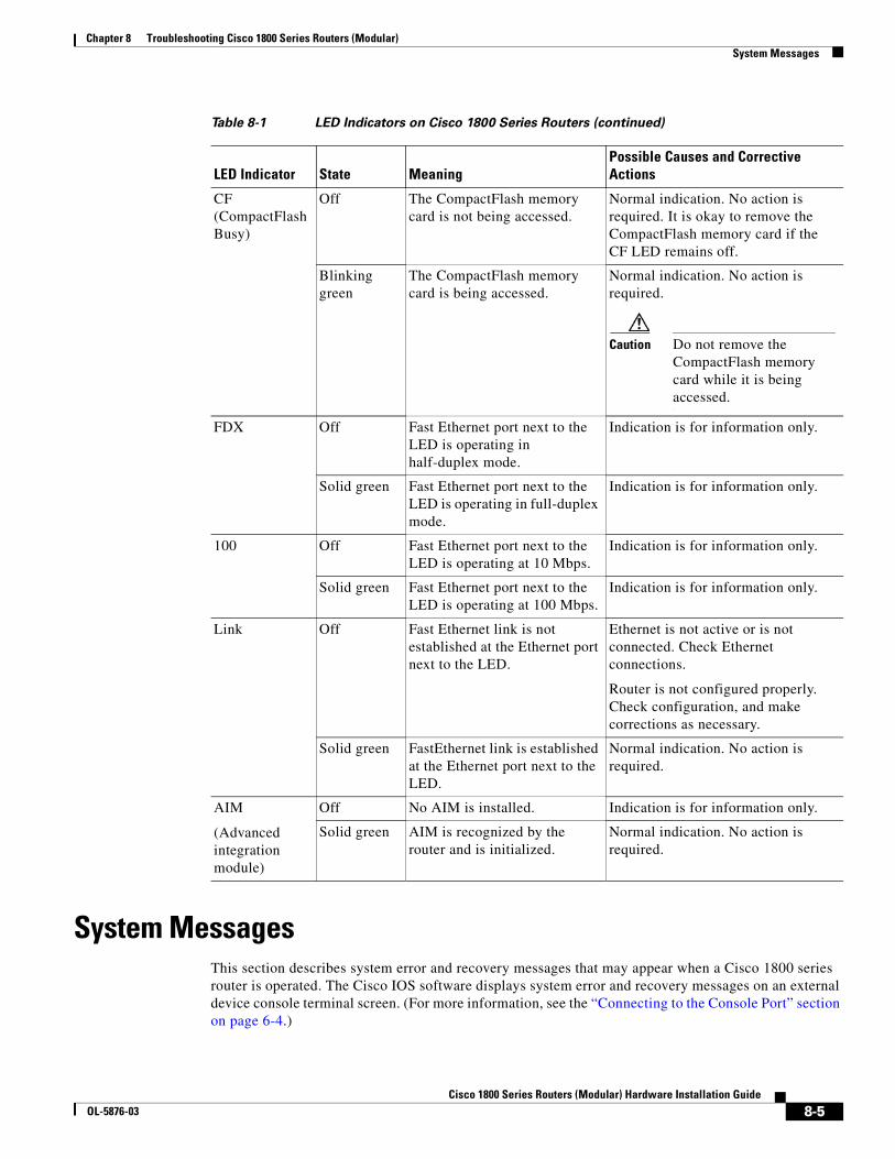
Chapter 8 Troubleshooting Cisco 1800 Series Routers (Modular) System Messages
System MessagesThis section describes system error and recovery messages that may appear when a Cisco 1800 series router is operated. The Cisco IOS software displays system error and recovery messages on an external device console terminal screen. (For more information, see the “Connecting to the Console Port” section on page 6-4.)
CF (CompactFlash Busy)
Off The CompactFlash memory card is not being accessed.
Normal indication. No action is required. It is okay to remove the CompactFlash memory card if the CF LED remains off.
Blinking green
The CompactFlash memory card is being accessed.
Normal indication. No action is required.
Caution Do not remove the CompactFlash memory card while it is being accessed.
FDX Off Fast Ethernet port next to the LED is operating in half-duplex mode.
Indication is for information only.
Solid green Fast Ethernet port next to the LED is operating in full-duplex mode.
Indication is for information only.
100 Off Fast Ethernet port next to the LED is operating at 10 Mbps.
Indication is for information only.
Solid green Fast Ethernet port next to the LED is operating at 100 Mbps.
Indication is for information only.
Link Off Fast Ethernet link is not established at the Ethernet port next to the LED.
Ethernet is not active or is not connected. Check Ethernet connections.
Router is not configured properly. Check configuration, and make corrections as necessary.
Solid green FastEthernet link is established at the Ethernet port next to the LED.
Normal indication. No action is required.
AIM
(Advanced integration module)
Off No AIM is installed. Indication is for information only.
Solid green AIM is recognized by the router and is initialized.
Normal indication. No action is required.
Table 8-1 LED Indicators on Cisco 1800 Series Routers (continued)
LED Indicator State MeaningPossible Causes and Corrective Actions
8-5Cisco 1800 Series Routers (Modular) Hardware Installation Guide
OL-5876-03
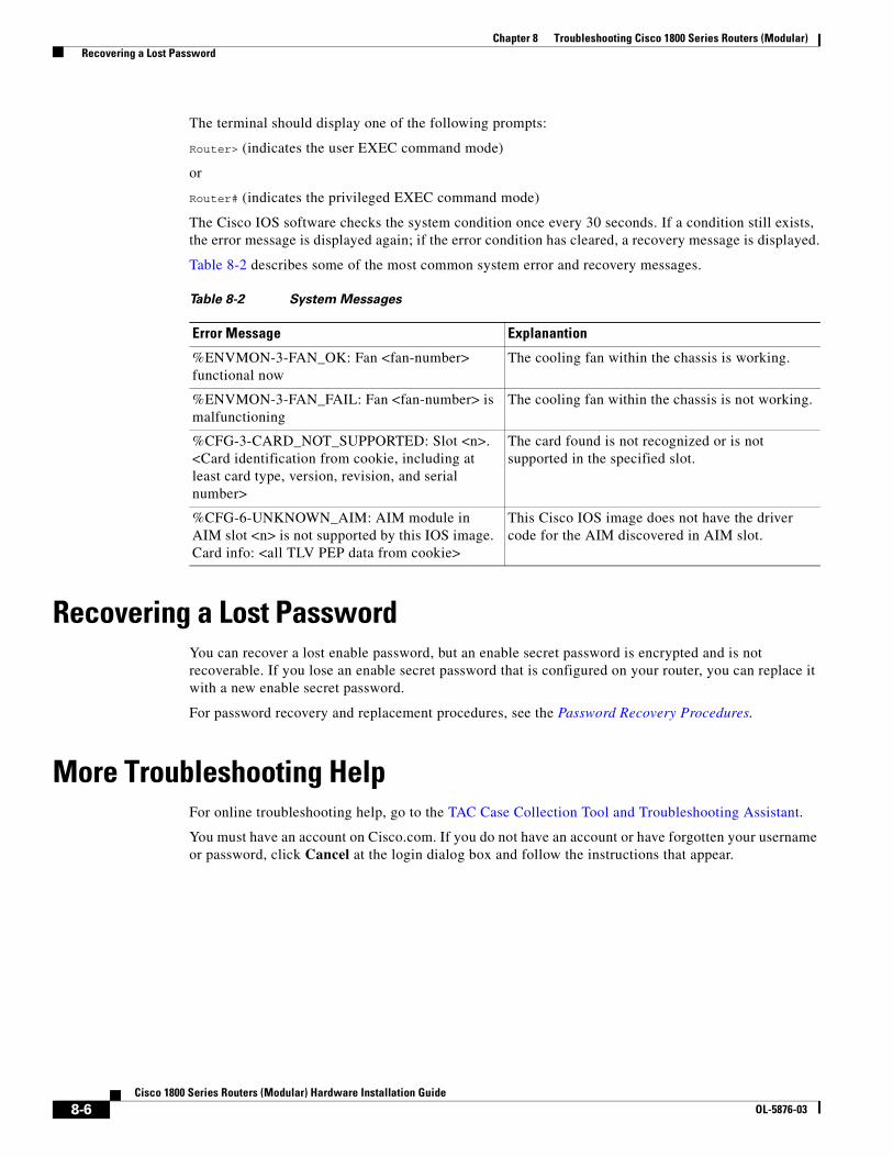
Chapter 8 Troubleshooting Cisco 1800 Series Routers (Modular) Recovering a Lost Password
The terminal should display one of the following prompts:
Router> (indicates the user EXEC command mode)
or
Router# (indicates the privileged EXEC command mode)
The Cisco IOS software checks the system condition once every 30 seconds. If a condition still exists, the error message is displayed again; if the error condition has cleared, a recovery message is displayed.
Table 8-2 describes some of the most common system error and recovery messages.
Recovering a Lost PasswordYou can recover a lost enable password, but an enable secret password is encrypted and is not recoverable. If you lose an enable secret password that is configured on your router, you can replace it with a new enable secret password.
For password recovery and replacement procedures, see the Password Recovery Procedures.
More Troubleshooting HelpFor online troubleshooting help, go to the TAC Case Collection Tool and Troubleshooting Assistant.
You must have an account on Cisco.com. If you do not have an account or have forgotten your username or password, click Cancel at the login dialog box and follow the instructions that appear.
Table 8-2 System Messages
Error Message Explanantion
%ENVMON-3-FAN_OK: Fan <fan-number> functional now
The cooling fan within the chassis is working.
%ENVMON-3-FAN_FAIL: Fan <fan-number> is malfunctioning
The cooling fan within the chassis is not working.
%CFG-3-CARD_NOT_SUPPORTED: Slot <n>. <Card identification from cookie, including at least card type, version, revision, and serial number>
The card found is not recognized or is not supported in the specified slot.
%CFG-6-UNKNOWN_AIM: AIM module in AIM slot <n> is not supported by this IOS image. Card info: <all TLV PEP data from cookie>
This Cisco IOS image does not have the driver code for the AIM discovered in AIM slot.
8-6Cisco 1800 Series Routers (Modular) Hardware Installation Guide
OL-5876-03
Cisco 1800 SeOL-5876-03
C H A P T E R 9
Installing Interface Cards in Cisco 1800 Series Routers (Modular)Cisco Interface Cards Installation GuideThe Cisco Interface Cards Installation Guide contains the procedures for installing the various types of interface cards in external chassis slots. Interface cards supported by the Cisco 1800 series integrated services routers (modular) include the following types:
• Voice-WAN interface cards (VWICs)—data only on the Cisco 1841 router
• WAN interface cards (WICs)
• High-speed WAN interface cards (HWICs)
You can view the Cisco Interface Cards Installation Guide on Cisco.com.
Related Product DocumentationThe following documentation is related to your product. This document was not shipped with your product, but you can access it on Cisco.com.
• Cisco Network Modules and Interface Cards Regulatory Compliance and Safety Information
Installing WICs, VWICs, and HWICsThis section describes how to install WICs, VWICs, and HWICs into Cisco 1800 series routers.
Caution Do not connect a WAN cable to an interface card until you have completed its installation procedure.
The Cisco 1841 router has two interface card slots. Each slot can accommodate a Cisco WIC, VWIC (data only mode), or a single-wide high-speed WIC (HWIC).
Note Cisco double-wide HWICs are not supported in the Cisco 1841 router.
9-1ries Routers (Modular) Hardware Installation Guide
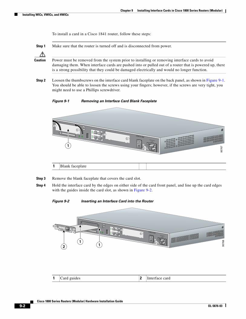
Chapter 9 Installing Interface Cards in Cisco 1800 Series Routers (Modular) Installing WICs, VWICs, and HWICs
To install a card in a Cisco 1841 router, follow these steps:
Step 1 Make sure that the router is turned off and is disconnected from power.
Caution Power must be removed from the system prior to installing or removing interface cards to avoid damaging them. When interface cards are pushed into or pulled out of a router that is powered up, there is a strong possibility that they could be damaged electrically and would no longer function.
Step 2 Loosen the thumbscrews on the interface card blank faceplate on the back panel, as shown in Figure 9-1. You should be able to loosen the screws using your fingers; however, if the screws are very tight, you might need to use a Phillips screwdriver.
Figure 9-1 Removing an Interface Card Blank Faceplate
Step 3 Remove the blank faceplate that covers the card slot.
Step 4 Hold the interface card by the edges on either side of the card front panel, and line up the card edges with the guides inside the card slot, as shown in Figure 9-2.
Figure 9-2 Inserting an Interface Card into the Router
1 Blank faceplate
9576
71
CISCO 1841100-240 VAC-1 A
50/60 Hz
1 Card guides 2 Interface card
9576
8
SEE MANUAL BEFORE INSTALLATION
DSU56K
CD
ALLPRDTD
11
2
CISCO 1841100-240 VAC-1 A
50/60 Hz
9-2Cisco 1800 Series Routers (Modular) Hardware Installation Guide
OL-5876-03

Chapter 9 Installing Interface Cards in Cisco 1800 Series Routers (Modular) Installing WICs, VWICs, and HWICs
Step 5 Insert the card in the slot, and gently push it into the router until the front panel of the card is flush with the back panel of the router.
Step 6 Tighten the screws.
9-3Cisco 1800 Series Routers (Modular) Hardware Installation Guide
OL-5876-03

Chapter 9 Installing Interface Cards in Cisco 1800 Series Routers (Modular) Installing WICs, VWICs, and HWICs
9-4Cisco 1800 Series Routers (Modular) Hardware Installation Guide
OL-5876-03

Cisco 1800 SeOL-5876-03
C H A P T E R 10
Installing and Replacing CompactFlash Memory Cards on Cisco 1800 Series Routers (Modular)This chapter describes installing and replacing CompactFlash memory cards in Cisco 1800 series integrated services routers (ISR) (modular). You can perform these procedures when the router has been installed in its working location with all power and interface cables connected. This chapter contains the following sections:
• Preventing Electrostatic Discharge Damage, page 10-1
• Replacing CompactFlash Memory Cards, page 10-1
Preventing Electrostatic Discharge DamageCompactFlash memory cards are sensitive to electrostatic discharge (ESD) damage. ESD damage, which can occur when electronic cards or components are handled improperly, results in intermittent or complete failures.
To prevent ESD damage, follow these guidelines:
• Always use an ESD wrist or ankle strap and ensure that it makes good skin contact.
• Connect the equipment end of the strap to an unfinished chassis surface.
• Place a removed CompactFlash memory card on an antistatic surface or in a static shielding bag. If the card will be returned to the factory, immediately place it in a static shielding bag.
• Avoid contact between the card and clothing. The wrist strap protects the card from ESD voltages on the body only; ESD voltages on clothing can still cause damage.
• Do not remove the wrist strap until the installation is complete.
Caution For safety, periodically check the resistance value of the antistatic strap. The measurement should be between 1 and 10 megohms (Mohms).
Replacing CompactFlash Memory CardsThis section describes how to remove and install CompactFlash memory cards.
10-1ries Routers (Modular) Hardware Installation Guide
Chapter 10 Installing and Replacing CompactFlash Memory Cards on Cisco 1800 Series Routers (Modular)
Removing a CompactFlash Memory Card
To remove a CompactFlash memory card from an external slot, follow these steps:
Caution If the CF LED is on or blinking, do not remove the CompactFlash memory card. The router could crash, or the flash memory contents could be corrupted.
Step 1 Press the ejector button next to the CompactFlash memory card. The ejector button moves outward so that it projects from the panel.
Step 2 Press the ejector button again to unseat the card.
Step 3 Carefully pull the card out of the slot.
Step 4 Place the removed CompactFlash memory card on an antistatic surface or in a static shielding bag.
Step 5 Push the ejector button in until it clicks.
Caution To prevent damage to the ejector mechanism, the ejector button must remain fully seated when not being used to eject a CompactFlash memory card.
Installing a CompactFlash Memory Card
To install a CompactFlash memory card, follow these steps:
Step 1 Make sure that the ejector button is fully seated so that it does not project from the panel.
Note If the ejector button projects from the panel, push it in until it clicks.
Step 2 With the label facing up, insert the connector end of the CompactFlash memory card into the slot until the card is seated in the connector. The card is keyed so that it cannot be inserted incorrectly.
Note If the ejector button projects from the panel after you insert the CompactFlash memory card, remove the card, press the ejector button until it clicks, and reinsert the card.
Caution To prevent damage to the ejector mechanism, the ejector button must remain fully seated when not being used to eject a CompactFlash memory card.
Using the Compact Flash GuardThe Compact Flash guard (CF-guard) provides protection for the compact flash memory slot.
10-2Cisco 1800 Series Routers (Modular) Hardware Installation Guide
OL-5876-03
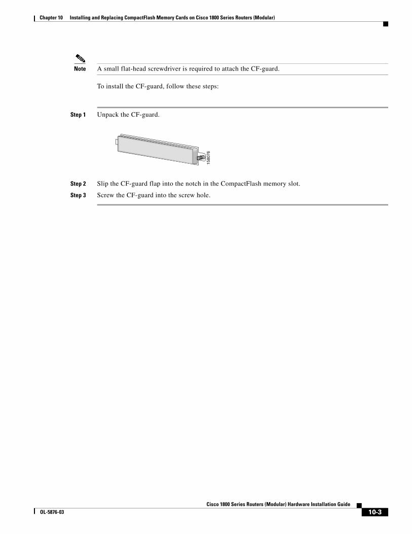
Chapter 10 Installing and Replacing CompactFlash Memory Cards on Cisco 1800 Series Routers (Modular)
Note A small flat-head screwdriver is required to attach the CF-guard.
To install the CF-guard, follow these steps:
Step 1 Unpack the CF-guard.
Step 2 Slip the CF-guard flap into the notch in the CompactFlash memory slot.
Step 3 Screw the CF-guard into the screw hole.
1580
76
10-3Cisco 1800 Series Routers (Modular) Hardware Installation Guide
OL-5876-03

Chapter 10 Installing and Replacing CompactFlash Memory Cards on Cisco 1800 Series Routers (Modular)
10-4Cisco 1800 Series Routers (Modular) Hardware Installation Guide
OL-5876-03
Cisco 1800 SeOL-5876-03
C H A P T E R 11
Installing and Upgrading Internal Modules in Cisco 1800 Series Routers (Modular)This chapter describes how to install or upgrade modules that are located internally within the Cisco 1800 series integrated services routers (modular): memory modules and advanced integration modules (AIMs). You need to remove the cover from the router to install or remove any of these items. The chapter contains the following sections:
• Safety Warnings, page 11-1
• Modules Internal to the Cisco 1841 Router, page 11-2
Note To see translations of the warnings that appear in this publication, see the Regulatory Compliance and Safety Information for Cisco 1840 Routers.
Safety Warnings
Warning Before working on a system that has an on/off switch, turn OFF the power and unplug the power cord. Statement 1
Warning Before working on equipment that is connected to power lines, remove jewelry (including rings, necklaces, and watches). Metal objects will heat up when connected to power and ground and can cause serious burns or weld the metal object to the terminals. Statement 43
Warning During this procedure, wear grounding wrist straps to avoid ESD damage to the card. Do not directly touch the backplane with your hand or any metal tool, or you could shock yourself. Statement 94
Warning Do not work on the system or connect or disconnect cables during periods of lightning activity. Statement 1001
Warning Read the installation instructions before you connect the system to its power source. Statement 1004
11-1ries Routers (Modular) Hardware Installation Guide
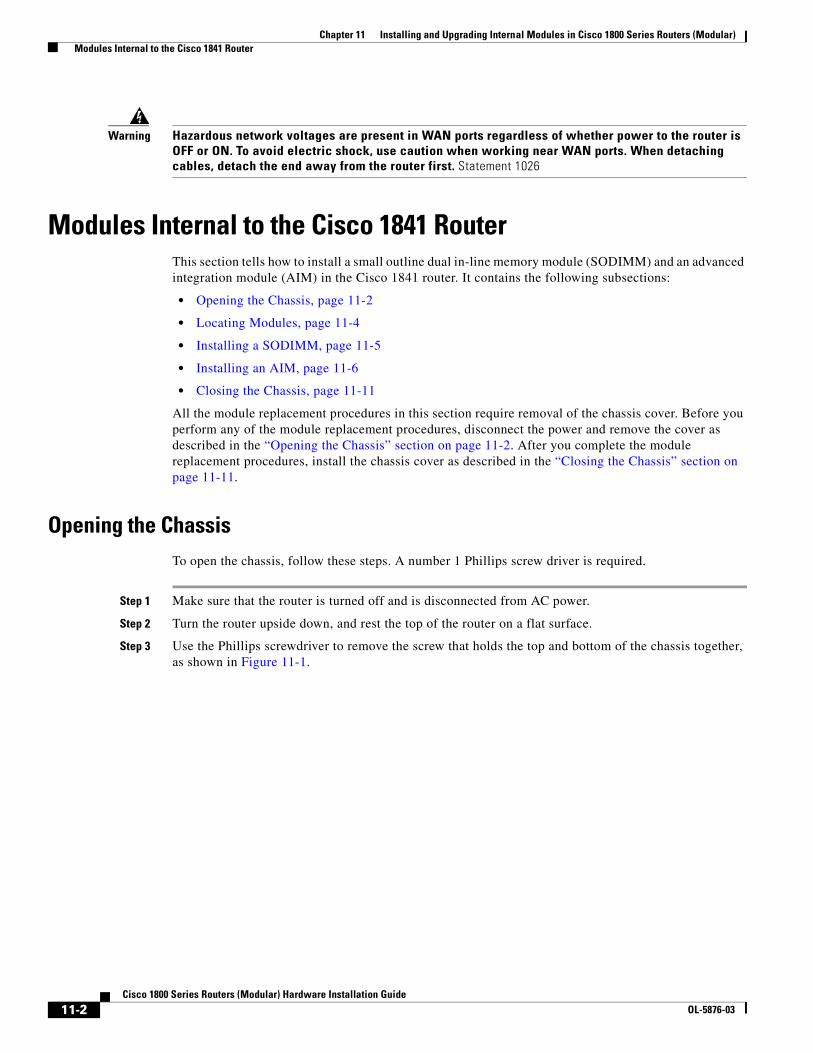
Chapter 11 Installing and Upgrading Internal Modules in Cisco 1800 Series Routers (Modular) Modules Internal to the Cisco 1841 Router
Warning Hazardous network voltages are present in WAN ports regardless of whether power to the router is OFF or ON. To avoid electric shock, use caution when working near WAN ports. When detaching cables, detach the end away from the router first. Statement 1026
Modules Internal to the Cisco 1841 RouterThis section tells how to install a small outline dual in-line memory module (SODIMM) and an advanced integration module (AIM) in the Cisco 1841 router. It contains the following subsections:
• Opening the Chassis, page 11-2
• Locating Modules, page 11-4
• Installing a SODIMM, page 11-5
• Installing an AIM, page 11-6
• Closing the Chassis, page 11-11
All the module replacement procedures in this section require removal of the chassis cover. Before you perform any of the module replacement procedures, disconnect the power and remove the cover as described in the “Opening the Chassis” section on page 11-2. After you complete the module replacement procedures, install the chassis cover as described in the “Closing the Chassis” section on page 11-11.
Opening the ChassisTo open the chassis, follow these steps. A number 1 Phillips screw driver is required.
Step 1 Make sure that the router is turned off and is disconnected from AC power.
Step 2 Turn the router upside down, and rest the top of the router on a flat surface.
Step 3 Use the Phillips screwdriver to remove the screw that holds the top and bottom of the chassis together, as shown in Figure 11-1.
11-2Cisco 1800 Series Routers (Modular) Hardware Installation Guide
OL-5876-03
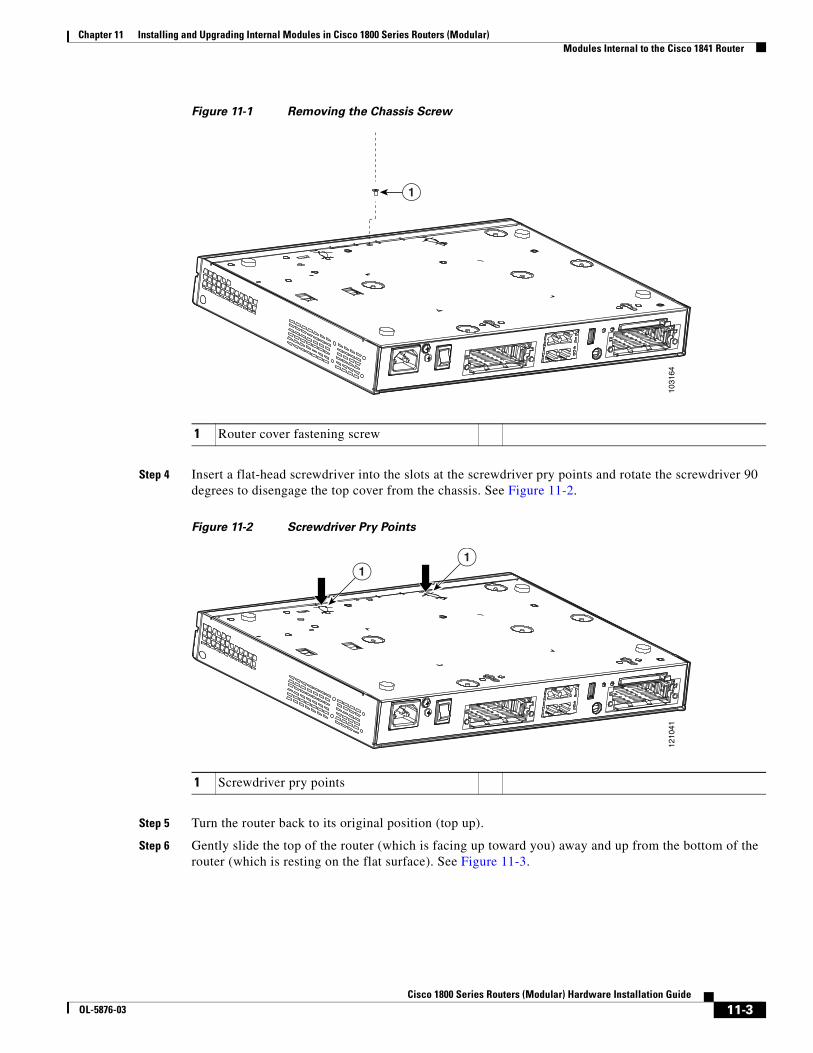
Chapter 11 Installing and Upgrading Internal Modules in Cisco 1800 Series Routers (Modular) Modules Internal to the Cisco 1841 Router
Figure 11-1 Removing the Chassis Screw
Step 4 Insert a flat-head screwdriver into the slots at the screwdriver pry points and rotate the screwdriver 90 degrees to disengage the top cover from the chassis. See Figure 11-2.
Figure 11-2 Screwdriver Pry Points
Step 5 Turn the router back to its original position (top up).
Step 6 Gently slide the top of the router (which is facing up toward you) away and up from the bottom of the router (which is resting on the flat surface). See Figure 11-3.
1 Router cover fastening screw
1031
64
1
1 Screwdriver pry points
1210
41
11
11-3Cisco 1800 Series Routers (Modular) Hardware Installation Guide
OL-5876-03
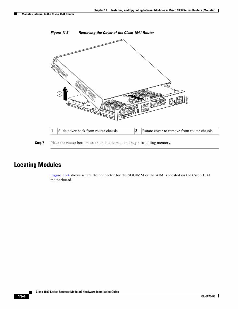
Chapter 11 Installing and Upgrading Internal Modules in Cisco 1800 Series Routers (Modular) Modules Internal to the Cisco 1841 Router
Figure 11-3 Removing the Cover of the Cisco 1841 Router
Step 7 Place the router bottom on an antistatic mat, and begin installing memory.
Locating ModulesFigure 11-4 shows where the connector for the SODIMM or the AIM is located on the Cisco 1841 motherboard.
1 Slide cover back from router chassis 2 Rotate cover to remove from router chassis
1031
6512
11-4Cisco 1800 Series Routers (Modular) Hardware Installation Guide
OL-5876-03
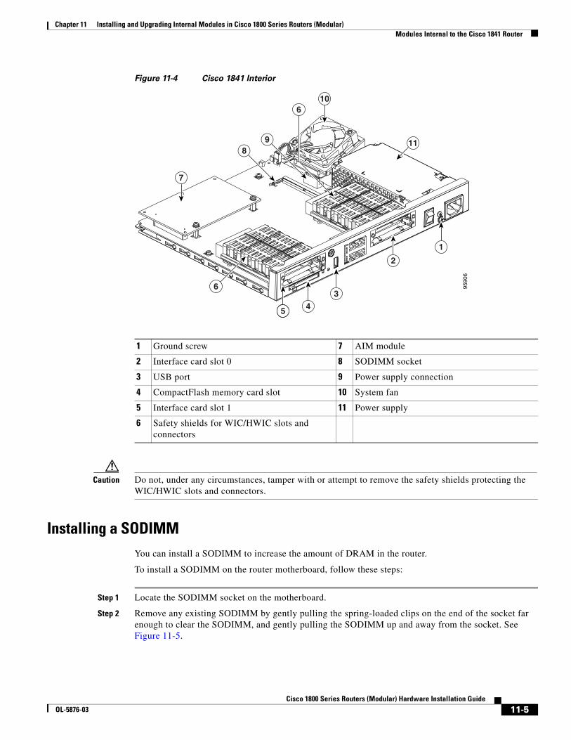
Chapter 11 Installing and Upgrading Internal Modules in Cisco 1800 Series Routers (Modular) Modules Internal to the Cisco 1841 Router
Figure 11-4 Cisco 1841 Interior
Caution Do not, under any circumstances, tamper with or attempt to remove the safety shields protecting the WIC/HWIC slots and connectors.
Installing a SODIMMYou can install a SODIMM to increase the amount of DRAM in the router.
To install a SODIMM on the router motherboard, follow these steps:
Step 1 Locate the SODIMM socket on the motherboard.
Step 2 Remove any existing SODIMM by gently pulling the spring-loaded clips on the end of the socket far enough to clear the SODIMM, and gently pulling the SODIMM up and away from the socket. See Figure 11-5.
1 Ground screw 7 AIM module
2 Interface card slot 0 8 SODIMM socket
3 USB port 9 Power supply connection
4 CompactFlash memory card slot 10 System fan
5 Interface card slot 1 11 Power supply
6 Safety shields for WIC/HWIC slots and connectors
10
7
1
2
3
45
6
89 11
15
6
9590
6
11-5Cisco 1800 Series Routers (Modular) Hardware Installation Guide
OL-5876-03
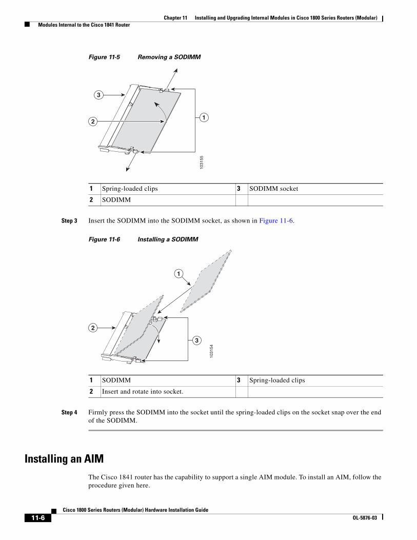
Chapter 11 Installing and Upgrading Internal Modules in Cisco 1800 Series Routers (Modular) Modules Internal to the Cisco 1841 Router
Figure 11-5 Removing a SODIMM
Step 3 Insert the SODIMM into the SODIMM socket, as shown in Figure 11-6.
Figure 11-6 Installing a SODIMM
Step 4 Firmly press the SODIMM into the socket until the spring-loaded clips on the socket snap over the end of the SODIMM.
Installing an AIMThe Cisco 1841 router has the capability to support a single AIM module. To install an AIM, follow the procedure given here.
1 Spring-loaded clips 3 SODIMM socket
2 SODIMM1
03
15
5
12
3
1 SODIMM 3 Spring-loaded clips
2 Insert and rotate into socket.
2
3
10
31
54
1
11-6Cisco 1800 Series Routers (Modular) Hardware Installation Guide
OL-5876-03
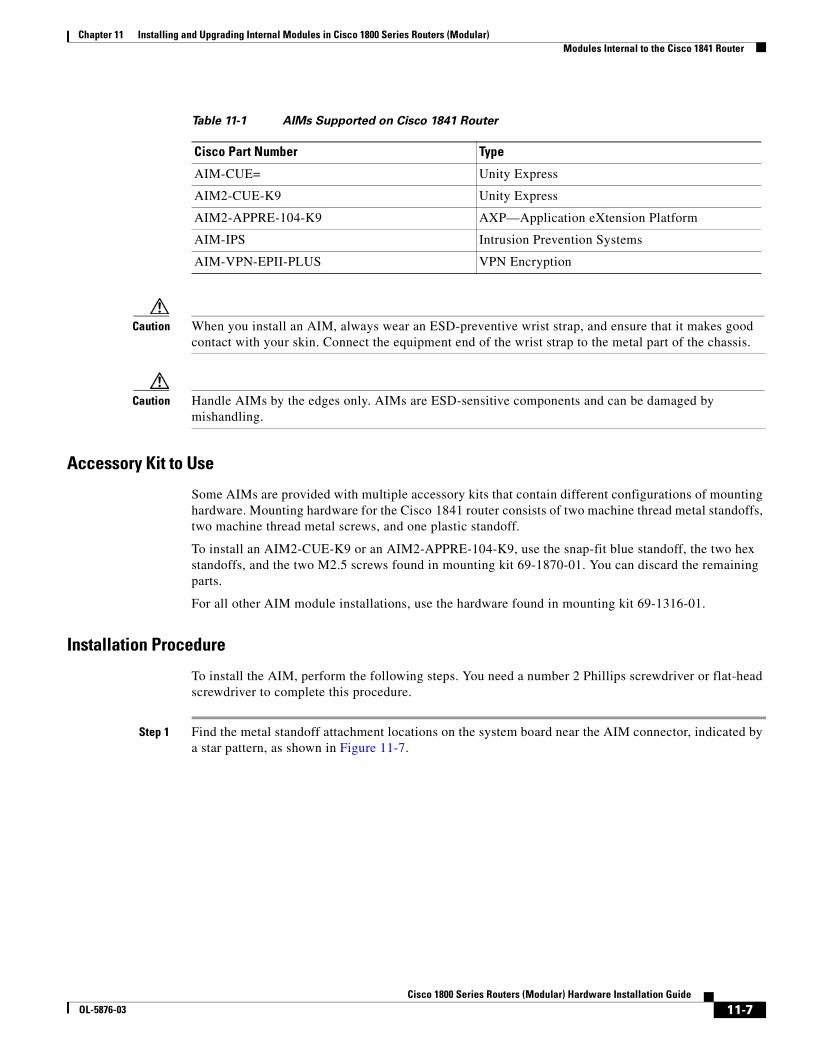
Chapter 11 Installing and Upgrading Internal Modules in Cisco 1800 Series Routers (Modular) Modules Internal to the Cisco 1841 Router
Caution When you install an AIM, always wear an ESD-preventive wrist strap, and ensure that it makes good contact with your skin. Connect the equipment end of the wrist strap to the metal part of the chassis.
Caution Handle AIMs by the edges only. AIMs are ESD-sensitive components and can be damaged by mishandling.
Accessory Kit to Use
Some AIMs are provided with multiple accessory kits that contain different configurations of mounting hardware. Mounting hardware for the Cisco 1841 router consists of two machine thread metal standoffs, two machine thread metal screws, and one plastic standoff.
To install an AIM2-CUE-K9 or an AIM2-APPRE-104-K9, use the snap-fit blue standoff, the two hex standoffs, and the two M2.5 screws found in mounting kit 69-1870-01. You can discard the remaining parts.
For all other AIM module installations, use the hardware found in mounting kit 69-1316-01.
Installation Procedure
To install the AIM, perform the following steps. You need a number 2 Phillips screwdriver or flat-head screwdriver to complete this procedure.
Step 1 Find the metal standoff attachment locations on the system board near the AIM connector, indicated by a star pattern, as shown in Figure 11-7.
Table 11-1 AIMs Supported on Cisco 1841 Router
Cisco Part Number Type
AIM-CUE= Unity Express
AIM2-CUE-K9 Unity Express
AIM2-APPRE-104-K9 AXP—Application eXtension Platform
AIM-IPS Intrusion Prevention Systems
AIM-VPN-EPII-PLUS VPN Encryption
11-7Cisco 1800 Series Routers (Modular) Hardware Installation Guide
OL-5876-03
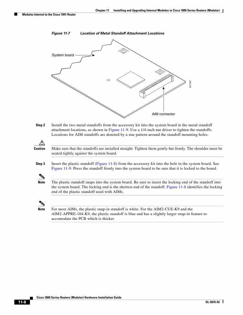
Chapter 11 Installing and Upgrading Internal Modules in Cisco 1800 Series Routers (Modular) Modules Internal to the Cisco 1841 Router
Figure 11-7 Location of Metal Standoff Attachment Locations
Step 2 Install the two metal standoffs from the accessory kit into the system board in the metal standoff attachment locations, as shown in Figure 11-9. Use a 1/4-inch nut driver to tighten the standoffs. Locations for AIM standoffs are denoted by a star pattern around the standoff mounting holes.
Caution Make sure that the standoffs are installed straight. Tighten them gently but firmly. The shoulder must be seated tightly against the system board.
Step 3 Insert the plastic standoff (Figure 11-8) from the accessory kit into the hole in the system board. See Figure 11-9. Press the standoff firmly into the system board to be sure that it is locked to the board.
Note The plastic standoff snaps into the system board. Be sure to insert the locking end of the standoff into the system board. The locking end is the shortest end of the standoff. Figure 11-8 identifies the locking end of the plastic standoff used with AIMs.
Note For most AIMs, the plastic snap-in standoff is white. For the AIM2-CUE-K9 and the AIM2-APPRE-104-K9, the plastic standoff is blue and has a slightly larger snap-in feature to accomodate the PCB which is thicker.
1211
07
System board
AIM connector
11-8Cisco 1800 Series Routers (Modular) Hardware Installation Guide
OL-5876-03
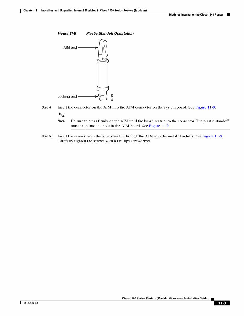
Chapter 11 Installing and Upgrading Internal Modules in Cisco 1800 Series Routers (Modular) Modules Internal to the Cisco 1841 Router
Figure 11-8 Plastic Standoff Orientation
Step 4 Insert the connector on the AIM into the AIM connector on the system board. See Figure 11-9.
Note Be sure to press firmly on the AIM until the board seats onto the connector. The plastic standoff must snap into the hole in the AIM board. See Figure 11-9.
Step 5 Insert the screws from the accessory kit through the AIM into the metal standoffs. See Figure 11-9. Carefully tighten the screws with a Phillips screwdriver.
8262
0
AIM end
Locking end
11-9Cisco 1800 Series Routers (Modular) Hardware Installation Guide
OL-5876-03
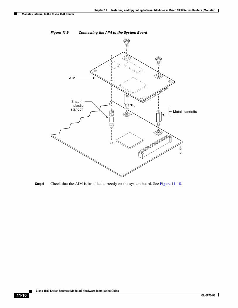
Chapter 11 Installing and Upgrading Internal Modules in Cisco 1800 Series Routers (Modular) Modules Internal to the Cisco 1841 Router
Figure 11-9 Connecting the AIM to the System Board
Step 6 Check that the AIM is installed correctly on the system board. See Figure 11-10.12
1108
Metal standoffs
Snap-inplastic
standoff
AIM
11-10Cisco 1800 Series Routers (Modular) Hardware Installation Guide
OL-5876-03
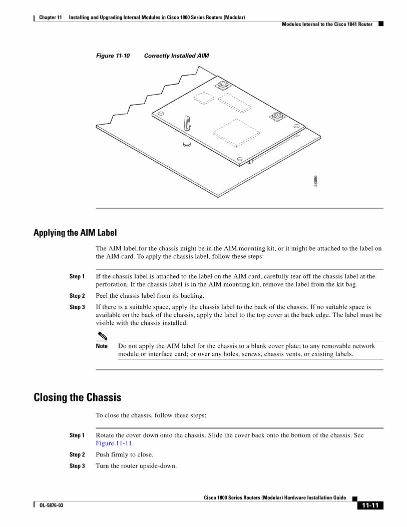
Chapter 11 Installing and Upgrading Internal Modules in Cisco 1800 Series Routers (Modular) Modules Internal to the Cisco 1841 Router
Figure 11-10 Correctly Installed AIM
Applying the AIM Label
The AIM label for the chassis might be in the AIM mounting kit, or it might be attached to the label on the AIM card. To apply the chassis label, follow these steps:
Step 1 If the chassis label is attached to the label on the AIM card, carefully tear off the chassis label at the perforation. If the chassis label is in the AIM mounting kit, remove the label from the kit bag.
Step 2 Peel the chassis label from its backing.
Step 3 If there is a suitable space, apply the chassis label to the back of the chassis. If no suitable space is available on the back of the chassis, apply the label to the top cover at the back edge. The label must be visible with the chassis installed.
Note Do not apply the AIM label for the chassis to a blank cover plate; to any removable network module or interface card; or over any holes, screws, chassis vents, or existing labels.
Closing the ChassisTo close the chassis, follow these steps:
Step 1 Rotate the cover down onto the chassis. Slide the cover back onto the bottom of the chassis. See Figure 11-11.
Step 2 Push firmly to close.
Step 3 Turn the router upside-down.
5869
6
11-11Cisco 1800 Series Routers (Modular) Hardware Installation Guide
OL-5876-03
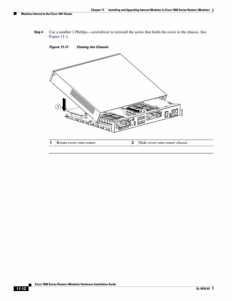
Chapter 11 Installing and Upgrading Internal Modules in Cisco 1800 Series Routers (Modular) Modules Internal to the Cisco 1841 Router
Step 4 Use a number 1 Phillips—screwdriver to reinstall the screw that holds the cover to the chassis. See Figure 11-1.
Figure 11-11 Closing the Chassis
1 Rotate cover onto router 2 Slide cover onto router chassis
1031
6621
11-12Cisco 1800 Series Routers (Modular) Hardware Installation Guide
OL-5876-03
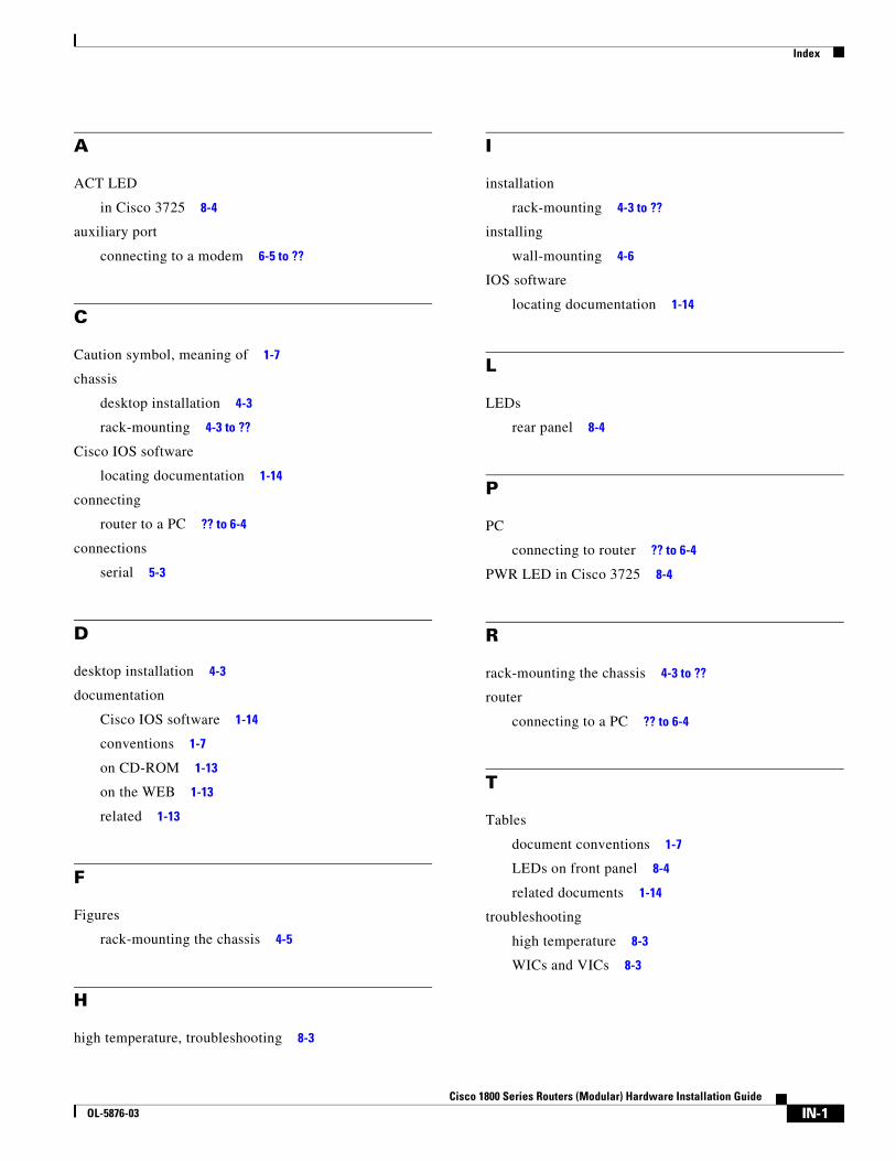
Index
A
ACT LED
in Cisco 3725 8-4
auxiliary port
connecting to a modem 6-5 to ??
C
Caution symbol, meaning of 1-7
chassis
desktop installation 4-3
rack-mounting 4-3 to ??
Cisco IOS software
locating documentation 1-14
connecting
router to a PC ?? to 6-4
connections
serial 5-3
D
desktop installation 4-3
documentation
Cisco IOS software 1-14
conventions 1-7
on CD-ROM 1-13
on the WEB 1-13
related 1-13
F
Figures
rack-mounting the chassis 4-5
H
high temperature, troubleshooting 8-3
CiscoOL-5876-03
I
installation
rack-mounting 4-3 to ??
installing
wall-mounting 4-6
IOS software
locating documentation 1-14
L
LEDs
rear panel 8-4
P
PC
connecting to router ?? to 6-4
PWR LED in Cisco 3725 8-4
R
rack-mounting the chassis 4-3 to ??
router
connecting to a PC ?? to 6-4
T
Tables
document conventions 1-7
LEDs on front panel 8-4
related documents 1-14
troubleshooting
high temperature 8-3
WICs and VICs 8-3
IN-1 1800 Series Routers (Modular) Hardware Installation Guide
Index
V
VICs
troubleshooting 8-3
W
wall-mounting 4-6
Warnings
WAN port voltages 5-5
WICs
troubleshooting 8-3
IN-2Cisco 1800 Series Routers (Modular) Hardware Installation Guide
OL-5876-03