
Cisco 1710 Security Router Software Configuration Guide 1710 Security... · CCNP, Cisco, the Cisco...
88
Corporate Headquarters Cisco Systems, Inc. 170 West Tasman Drive San Jose, CA 95134-1706 USA http://www.cisco.com Tel: 408 526-4000 800 553-NETS (6387) Fax: 408 526-4100 Cisco 1710 Security Router Software Configuration Guide Customer Order Number: DOC-7812696= Text Part Number: 78-12696-01
Transcript of Cisco 1710 Security Router Software Configuration Guide 1710 Security... · CCNP, Cisco, the Cisco...

Corporate HeadquartersCisco Systems, Inc.170 West Tasman DriveSan Jose, CA 95134-1706USAhttp://www.cisco.comTel: 408 526-4000
800 553-NETS (6387)Fax: 408 526-4100
Cisco 1710 Security Router Software Configuration Guide
Customer Order Number: DOC-7812696=Text Part Number: 78-12696-01

THE SPECIFICATIONS AND INFORMATION REGARDING THE PRODUCTS IN THIS MANUAL ARE SUBJECT TO CHANGE WITHOUT NOTICE. ALL STATEMENTS, INFORMATION, AND RECOMMENDATIONS IN THIS MANUAL ARE BELIEVED TO BE ACCURATE BUT ARE PRESENTED WITHOUT WARRANTY OF ANY KIND, EXPRESS OR IMPLIED. USERS MUST TAKE FULL RESPONSIBILITY FOR THEIR APPLICATION OF ANY PRODUCTS.
THE SOFTWARE LICENSE AND LIMITED WARRANTY FOR THE ACCOMPANYING PRODUCT ARE SET FORTH IN THE INFORMATION PACKET THAT SHIPPED WITH THE PRODUCT AND ARE INCORPORATED HEREIN BY THIS REFERENCE. IF YOU ARE UNABLE TO LOCATE THE SOFTWARE LICENSE OR LIMITED WARRANTY, CONTACT YOUR CISCO REPRESENTATIVE FOR A COPY.
The following information is for FCC compliance of Class A devices: This equipment has been tested and found to comply with the limits for a Class A digital device, pursuant to part 15 of the FCC rules. These limits are designed to provide reasonable protection against harmful interference when the equipment is operated in a commercial environment. This equipment generates, uses, and can radiate radio-frequency energy and, if not installed and used in accordance with the instruction manual, may cause harmful interference to radio communications. Operation of this equipment in a residential area is likely to cause harmful interference, in which case users will be required to correct the interference at their own expense.
The following information is for FCC compliance of Class B devices: The equipment described in this manual generates and may radiate radio-frequency energy. If it is not installed in accordance with Cisco’s installation instructions, it may cause interference with radio and television reception. This equipment has been tested and found to comply with the limits for a Class B digital device in accordance with the specifications in part 15 of the FCC rules. These specifications are designed to provide reasonable protection against such interference in a residential installation. However, there is no guarantee that interference will not occur in a particular installation.
Modifying the equipment without Cisco’s written authorization may result in the equipment no longer complying with FCC requirements for Class A or Class B digital devices. In that event, your right to use the equipment may be limited by FCC regulations, and you may be required to correct any interference to radio or television communications at your own expense.
You can determine whether your equipment is causing interference by turning it off. If the interference stops, it was probably caused by the Cisco equipment or one of its peripheral devices. If the equipment causes interference to radio or television reception, try to correct the interference by using one or more of the following measures:
• Turn the television or radio antenna until the interference stops.
• Move the equipment to one side or the other of the television or radio.
• Move the equipment farther away from the television or radio.
• Plug the equipment into an outlet that is on a different circuit from the television or radio. (That is, make certain the equipment and the television or radio are on circuits controlled by different circuit breakers or fuses.)
Modifications to this product not authorized by Cisco Systems, Inc. could void the FCC approval and negate your authority to operate the product.
The Cisco implementation of TCP header compression is an adaptation of a program developed by the University of California, Berkeley (UCB) as part of UCB’s public domain version of the UNIX operating system. All rights reserved. Copyright © 1981, Regents of the University of California.
NOTWITHSTANDING ANY OTHER WARRANTY HEREIN, ALL DOCUMENT FILES AND SOFTWARE OF THESE SUPPLIERS ARE PROVIDED “AS IS” WITH ALL FAULTS. CISCO AND THE ABOVE-NAMED SUPPLIERS DISCLAIM ALL WARRANTIES, EXPRESSED OR IMPLIED, INCLUDING, WITHOUT LIMITATION, THOSE OF MERCHANTABILITY, FITNESS FOR A PARTICULAR PURPOSE AND NONINFRINGEMENT OR ARISING FROM A COURSE OF DEALING, USAGE, OR TRADE PRACTICE.
IN NO EVENT SHALL CISCO OR ITS SUPPLIERS BE LIABLE FOR ANY INDIRECT, SPECIAL, CONSEQUENTIAL, OR INCIDENTAL DAMAGES, INCLUDING, WITHOUT LIMITATION, LOST PROFITS OR LOSS OR DAMAGE TO DATA ARISING OUT OF THE USE OR INABILITY TO USE THIS MANUAL, EVEN IF CISCO OR ITS SUPPLIERS HAVE BEEN ADVISED OF THE POSSIBILITY OF SUCH DAMAGES.
AccessPath, AtmDirector, Browse with Me, CCDE, CCIP, CCSI, CD-PAC, CiscoLink, the Cisco NetWorks logo, the Cisco Powered Network logo, Cisco Systems Networking Academy, the Cisco Systems Networking Academy logo, Fast Step, Follow Me Browsing, FormShare, FrameShare, GigaStack, IGX, Internet Quotient, IP/VC, iQ Breakthrough, iQ Expertise, iQ FastTrack, the iQ Logo, iQ Net Readiness Scorecard, MGX, the Networkers logo, Packet, RateMUX, ScriptBuilder, ScriptShare, SlideCast, SMARTnet, TransPath, Unity, Voice LAN, Wavelength Router, and WebViewer are trademarks of Cisco Systems, Inc.; Changing the Way We Work, Live, Play, and Learn, Discover All That’s Possible, and Empowering the Internet Generation, are service marks of Cisco Systems, Inc.; and Aironet, ASIST, BPX, Catalyst, CCDA, CCDP, CCIE, CCNA, CCNP, Cisco, the Cisco Certified Internetwork Expert logo, Cisco IOS, the Cisco IOS logo, Cisco Systems, Cisco Systems Capital, the Cisco Systems

logo, Enterprise/Solver, EtherChannel, EtherSwitch, FastHub, FastSwitch, IOS, IP/TV, LightStream, MICA, Network Registrar, PIX, Post-Routing, Pre-Routing, Registrar, StrataView Plus, Stratm, SwitchProbe, TeleRouter, and VCO are registered trademarks of Cisco Systems, Inc. and/or its affiliates in the U.S. and certain other countries.
All other trademarks mentioned in this document or Web site are the property of their respective owners. The use of the word partner does not imply a partnership relationship between Cisco and any other company. (0105R)
Cisco 1710 Security Router Software Configuration GuideCopyright © 2001, Cisco Systems, Inc.All rights reserved.


78-12696-01
C O N T E N T S
Preface xi
Objectives xi
Audience xi
Organization xii
Conventions xii
Related Documentation xiii
Obtaining Documentation xivWorld Wide Web xivDocumentation CD-ROM xivOrdering Documentation xivDocumentation Feedback xv
Obtaining Technical Assistance xvCisco.com xviTechnical Assistance Center xvi
Contacting TAC by Using the Cisco TAC Website xviContacting TAC by Telephone xvii
C H A P T E R 1 Introduction to Router Configuration 1-1
Configuring the Router from a PC 1-2
Understanding Command Modes 1-2
Getting Help 1-6
Enable Secret and Enable Passwords 1-7
Entering Configuration Mode 1-8
vCisco 1710 Security Router Software Configuration Guide

Contents
Using Commands 1-9Abbreviating Commands 1-9Command-Line Error Messages 1-9Undoing Commands 1-10
Saving Configuration Changes 1-10
Using Debug Commands 1-11
Where to Go Next 1-12
C H A P T E R 2 Cisco 1710 Security Router Configuration 2-1
Before You Configure Your Network 2-2
Configuring a Virtual Private Dialup Network 2-2
Configuring IP Security 2-3Disabling Hardware Encryption 2-4
Configuring the Dialer Interface 2-6
Configuring the Ethernet Interfaces 2-7
Configuring Dynamic Host Configuration Protocol 2-8Configuration Example 2-8Manual Binding Configuration Example 2-9
Configuring Network Address Translation 2-10Configuration Example 2-11
Configuring Firewalls 2-12Access Lists 2-13
Configuration Examples 2-14Inspection Rules 2-15
Complete Sample Configuration 2-15Cisco 1710 Security Router Configuration 2-17Network Access Router Configuration 2-19
viCisco 1710 Security Router Software Configuration Guide
78-12696-01

Contents
C H A P T E R 3 Overview of Routing Between Virtual LANs 3-1
What Is a VLAN? 3-1LAN Segmentation 3-2Security 3-3Broadcast Control 3-3Performance 3-4Network Management 3-4Communication Between VLANs 3-4
VLAN Colors 3-4
Why Implement VLANs? 3-5
Communicating Between VLANs 3-5VLAN Translation 3-6
Designing Switched VLANs 3-6
C H A P T E R 4 Configuring Routing Between VLANs with IEEE 802.1Q Encapsulation 4-1
IEEE 802.1Q Encapsulation Configuration Task List 4-1Configuring AppleTalk Routing over IEEE 802.1Q 4-2
Enabling AppleTalk Routing 4-2Configuring AppleTalk on the Subinterface 4-3Defining the VLAN Encapsulation Format 4-3
Configuring IP Routing over IEEE 802.1Q 4-3Enabling IP Routing 4-4Defining the VLAN Encapsulation Format 4-4Assigning an IP Address to a Network Interface 4-5
Configuring IPX Routing over IEEE 802.1Q 4-5Enabling NetWare Routing 4-5Defining the VLAN Encapsulation Format 4-6Configuring NetWare on the Subinterface 4-6
viiCisco 1710 Security Router Software Configuration Guide
78-12696-01

Contents
Examples of IEEE 802.1Q Encapsulation Configuration 4-6Configuring AppleTalk over IEEE 802.1Q 4-7Configuring IP Routing over IEEE 802.1Q 4-7Configuring IPX Routing over IEEE 802.1Q 4-7
VLAN Commands 4-8clear vlan statistics 4-8
Syntax Description 4-8Default 4-8Command Mode 4-8Example 4-8
debug vlan packets 4-9Syntax Description 4-9Command Mode 4-9Usage Guidelines 4-9Example 4-9
encapsulation dot1q 4-10Syntax Description 4-10Default 4-10Command Mode 4-10Usage Guidelines 4-10Example 4-10
show vlans 4-11Syntax Description 4-11Command Mode 4-11Example 4-11
A P P E N D I X A ROM Monitor A-1
Entering the ROM Monitor A-1
ROM Monitor Commands A-3
Command Descriptions A-4
viiiCisco 1710 Security Router Software Configuration Guide
78-12696-01

Contents
Disaster Recovery with TFTP Download A-5TFTP Download Command Variables A-5
Required Variables A-6Optional Variables A-7
Using the TFTP Download Command A-8
Configuration Register A-9
Console Download A-10Command Description A-11Error Reporting A-12
Debug Commands A-12
I N D E X
ixCisco 1710 Security Router Software Configuration Guide
78-12696-01

Contents
xCisco 1710 Security Router Software Configuration Guide
78-12696-01

Preface
This preface describes the objectives, audience, organization, and conventions of the Cisco 1710 Security Router Software Configuration Guide. It also provides information about additional documentation and how to obtain technical assistance.
ObjectivesThis software configuration guide explains how to configure the Cisco 1710 router. It does not cover every feature, but does describe, in detail, the tasks most commonly required to configure the router.
This guide also references detailed features described in the Cisco IOS configuration guides and command references. Refer to these other books for additional information.
AudienceThis guide is intended primarily for the following audiences:
• Enterprise companies with remote or small branch offices connecting to corporate site and branch offices (site-to-site connection), or between branch offices through secure Virtual Private Network (VPN) tunnels.
• Small and medium size businesses needing to provide mobile users with secure VPN access to network resources at the central site; or connect to partner locations through a secure tunnel.
xiCisco 1710 Security Router Software Configuration Guide
78-12696-01

PrefaceOrganization
• Service providers offering VPN services to enterprise and small-to-medium sized businesses. Service providers can bundle Cisco VPN hardware with their service offerings.
• Providers of Internet connections to the whole multi-tenant office building.
OrganizationThis document contains the following chapters and appendix:
• Chapter 1, “Introduction to Router Configuration”—Describes briefly the configuration of a router through Cisco IOS.
• Chapter 2, “Cisco 1710 Security Router Configuration”—Describes what you need to know about the Cisco IOS software (the software that runs the router) before you begin to configure the router.
• Chapter 3, “Overview of Routing Between Virtual LANs”—Provides an overview of virtual LANs (VLANs).
• Chapter 4, “Configuring Routing Between VLANs with IEEE 802.1Q Encapsulation”—Describes the required and optional tasks for configuring routing between VLANs with IEEE 802.1Q encapsulation.
• Appendix A, “ROM Monitor”—Describes the functions and commands of the router ROM monitor (also called the bootstrap program), the firmware that runs when the router is powered up or reset.
ConventionsThis document uses the following conventions:
• The caret character (^) represents the Control key.
For example, the key combinations ^D and Ctrl-D are equivalent: Both mean hold down the Control key while you press the D key. Keys are indicated in capitals, but are not case sensitive.
Command descriptions use these conventions:
• Commands and keywords in boldface font.
• Variables for which you supply values are in italic font.
xiiCisco 1710 Security Router Software Configuration Guide
78-12696-01
PrefaceRelated Documentation
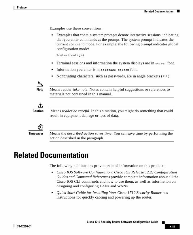
Examples use these conventions:
• Examples that contain system prompts denote interactive sessions, indicating that you enter commands at the prompt. The system prompt indicates the current command mode. For example, the following prompt indicates global configuration mode:
Router(config)#
• Terminal sessions and information the system displays are in screen font.
• Information you enter is in boldface screen font.
• Nonprinting characters, such as passwords, are in angle brackets (< >).
Note Means reader take note. Notes contain helpful suggestions or references to materials not contained in this manual.
Caution Means reader be careful. In this situation, you might do something that could result in equipment damage or loss of data.
Timesaver Means the described action saves time. You can save time by performing the action described in the paragraph.
Related DocumentationThe following publications provide related information on this product:
• Cisco IOS Software Configuration: Cisco IOS Release 12.2: Configuration Guides and Command References provide complete information about all the Cisco IOS CLI commands and how to use them, as well as information on designing and configuring LANs and WANs.
• Quick Start Guide for Installing Your Cisco 1710 Security Router has instructions for quickly cabling and powering up the router.
xiiiCisco 1710 Security Router Software Configuration Guide
78-12696-01
PrefaceObtaining Documentation
• Cisco 1710 Security Router Hardware Installation Guide describes router features, how to install and cable the router, and how to troubleshoot common problems you may have with it.
Obtaining DocumentationThe following sections provide sources for obtaining documentation from Cisco Systems.
World Wide WebYou can access the most current Cisco documentation on the World Wide Web at the following sites:
• http://www.cisco.com
• http://www-china.cisco.com
• http://www-europe.cisco.com
Documentation CD-ROMCisco documentation and additional literature are available in a CD-ROM package, which ships with your product. The Documentation CD-ROM is updated monthly and may be more current than printed documentation. The CD-ROM package is available as a single unit or as an annual subscription.
Ordering DocumentationCisco documentation is available in the following ways:
• Registered Cisco Direct Customers can order Cisco Product documentation from the Networking Products MarketPlace:
http://www.cisco.com/cgi-bin/order/order_root.pl
xivCisco 1710 Security Router Software Configuration Guide
78-12696-01

PrefaceObtaining Technical Assistance
• Registered Cisco.com users can order the Documentation CD-ROM through the online Subscription Store:
http://www.cisco.com/go/subscription
• Nonregistered Cisco.com users can order documentation through a local account representative by calling Cisco corporate headquarters (California, USA) at 408 526-7208 or, in North America, by calling 800 553-NETS(6387).
Documentation FeedbackIf you are reading Cisco product documentation on the World Wide Web, you can submit technical comments electronically. Click Feedback in the toolbar and select Documentation. After you complete the form, click Submit to send it to Cisco.
You can e-mail your comments to [email protected].
To submit your comments by mail, use the response card behind the front cover of your document, or write to the following address:
Attn Document Resource ConnectionCisco Systems, Inc.170 West Tasman DriveSan Jose, CA 95134-9883
We appreciate your comments.
Obtaining Technical AssistanceCisco provides Cisco.com as a starting point for all technical assistance. Customers and partners can obtain documentation, troubleshooting tips, and sample configurations from online tools. For Cisco.com registered users, additional troubleshooting tools are available from the TAC website.
xvCisco 1710 Security Router Software Configuration Guide
78-12696-01

PrefaceObtaining Technical Assistance
Cisco.comCisco.com is the foundation of a suite of interactive, networked services that provides immediate, open access to Cisco information and resources at anytime, from anywhere in the world. This highly integrated Internet application is a powerful, easy-to-use tool for doing business with Cisco.
Cisco.com provides a broad range of features and services to help customers and partners streamline business processes and improve productivity. Through Cisco.com, you can find information about Cisco and our networking solutions, services, and programs. In addition, you can resolve technical issues with online technical support, download and test software packages, and order Cisco learning materials and merchandise. Valuable online skill assessment, training, and certification programs are also available.
Customers and partners can self-register on Cisco.com to obtain additional personalized information and services. Registered users can order products, check on the status of an order, access technical support, and view benefits specific to their relationships with Cisco.
To access Cisco.com, go to the following website:
http://www.cisco.com
Technical Assistance CenterThe Cisco TAC website is available to all customers who need technical assistance with a Cisco product or technology that is under warranty or covered by a maintenance contract.
Contacting TAC by Using the Cisco TAC Website
If you have a priority level 3 (P3) or priority level 4 (P4) problem, contact TAC by going to the TAC website:
http://www.cisco.com/tac
xviCisco 1710 Security Router Software Configuration Guide
78-12696-01

PrefaceObtaining Technical Assistance
P3 and P4 level problems are defined as follows:
• P3—Your network performance is degraded. Network functionality is noticeably impaired, but most business operations continue.
• P4—You need information or assistance on Cisco product capabilities, product installation, or basic product configuration.
In each of the above cases, use the Cisco TAC website to quickly find answers to your questions.
To register for Cisco.com, go to the following website:
http://www.cisco.com/register/
If you cannot resolve your technical issue by using the TAC online resources, Cisco.com registered users can open a case online by using the TAC Case Open tool at the following website:
http://www.cisco.com/tac/caseopen
Contacting TAC by Telephone
If you have a priority level 1 (P1) or priority level 2 (P2) problem, contact TAC by telephone and immediately open a case. To obtain a directory of toll-free numbers for your country, go to the following website:
http://www.cisco.com/warp/public/687/Directory/DirTAC.shtml
P1 and P2 level problems are defined as follows:
• P1—Your production network is down, causing a critical impact to business operations if service is not restored quickly. No workaround is available.
• P2—Your production network is severely degraded, affecting significant aspects of your business operations. No workaround is available.
xviiCisco 1710 Security Router Software Configuration Guide
78-12696-01

PrefaceObtaining Technical Assistance
xviiiCisco 1710 Security Router Software Configuration Guide
78-12696-01

Cisco 1710 Security Rou78-12696-01
C H A P T E R 1
Introduction to Router ConfigurationIf you understand Cisco IOS software (the software that runs your router) and you are experienced in configuring network devices, you can use the Cisco IOS command-line interface (CLI) to configure your router. The purpose of this guide is to help you use Cisco IOS software to configure your Cisco 1710 Security router. This chapter describes what you need to know before you begin configuring your router with Cisco IOS software.
This chapter contains the following sections:
• Configuring the Router from a PC
• Understanding Command Modes
• Getting Help
• Enable Secret and Enable Passwords
• Entering Configuration Mode
• Using Commands
• Saving Configuration Changes
• Using Debug Commands
• Where to Go Next
Understanding these concepts saves you time when you are configuring your router. If you have never used the Cisco IOS software or need a refresher, take a few minutes to read this chapter before you proceed to the next chapter.
If you are already familiar with the Cisco IOS software, you can proceed to the configuration chapter that is appropriate for your network.
1-1ter Software Configuration Guide
Chapter 1 Introduction to Router ConfigurationConfiguring the Router from a PC
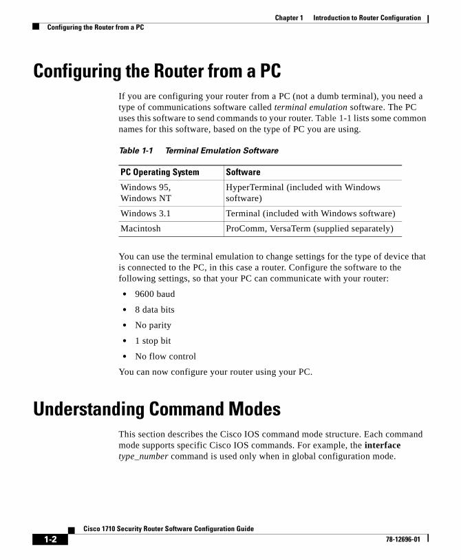
Configuring the Router from a PCIf you are configuring your router from a PC (not a dumb terminal), you need a type of communications software called terminal emulation software. The PC uses this software to send commands to your router. Table 1-1 lists some common names for this software, based on the type of PC you are using.
You can use the terminal emulation to change settings for the type of device that is connected to the PC, in this case a router. Configure the software to the following settings, so that your PC can communicate with your router:
• 9600 baud
• 8 data bits
• No parity
• 1 stop bit
• No flow control
You can now configure your router using your PC.
Understanding Command ModesThis section describes the Cisco IOS command mode structure. Each command mode supports specific Cisco IOS commands. For example, the interface type_number command is used only when in global configuration mode.
Table 1-1 Terminal Emulation Software
PC Operating System Software
Windows 95, Windows NT
HyperTerminal (included with Windows software)
Windows 3.1 Terminal (included with Windows software)
Macintosh ProComm, VersaTerm (supplied separately)
1-2Cisco 1710 Security Router Software Configuration Guide
78-12696-01

Chapter 1 Introduction to Router ConfigurationUnderstanding Command Modes
You use the following Cisco IOS command modes when configuring the scenarios described in this document:
• User EXEC
• Privileged EXEC
• Global configuration
• Interface configuration
• Router configuration
• Line configuration
Note Throughout the examples in this guide, there are steps for verifying your router configuration by using different Cisco IOS commands. If you plan to use these verification steps, you must understand how to change from one command mode to another, as summarized in Table 1-2.
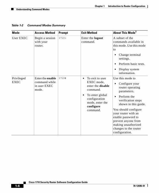
Table 1-2 lists the command modes that are used in this guide, how to access each mode, the prompt you see in that mode, and how to exit that mode. The examples in the table use the host name 1710.
1-3Cisco 1710 Security Router Software Configuration Guide
78-12696-01
Chapter 1 Introduction to Router ConfigurationUnderstanding Command Modes
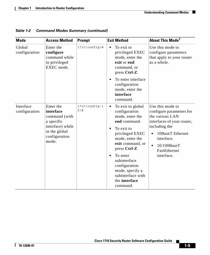
Table 1-2 Command Modes Summary
Mode Access Method Prompt Exit Method About This Mode1
User EXEC Begin a session with your router.
1710> Enter the logout command.
A subset of the commands available in this mode. Use this mode to
• Change terminal settings.
• Perform basic tests.
• Display system information.
Privileged EXEC
Enter the enable command while in user EXEC mode.
1710# • To exit to user EXEC mode, enter the disable command.
• To enter global configuration mode, enter the configure command.
Use this mode to
• Configure your router operating parameters.
• Perform the verification steps shown in this guide.
You should configure your router with an enable password to prevent anyone from making unauthorized changes to the router configuration.
1-4Cisco 1710 Security Router Software Configuration Guide
78-12696-01
Chapter 1 Introduction to Router ConfigurationUnderstanding Command Modes
Global configuration
Enter the configure command while in privileged EXEC mode.
1710(config)# • To exit to privileged EXEC mode, enter the exit or end command, or press Ctrl-Z.
• To enter interface configuration mode, enter the interface command.
Use this mode to configure parameters that apply to your router as a whole.
Interface configuration
Enter the interface command (with a specific interface) while in the global configuration mode.
1710(config-if)#
• To exit to global configuration mode, enter the end command.
• To exit to privileged EXEC mode, enter the exit command, or press Ctrl-Z.
• To enter subinterface configuration mode, specify a subinterface with the interface command.
Use this mode to configure parameters for the various LAN interfaces of your router, including the
• 10BaseT Ethernet interface.
• 10/100BaseT FastEthernet interface.
Table 1-2 Command Modes Summary (continued)
Mode Access Method Prompt Exit Method About This Mode1
1-5Cisco 1710 Security Router Software Configuration Guide
78-12696-01

Chapter 1 Introduction to Router ConfigurationGetting Help
Getting HelpYou can use the question mark (?) and arrow keys to help you enter commands. Here are some ways to get help while in any command mode:
• Enter a question mark to list the commands that are available in the current mode. You can restrict the list to all commands starting with a specific letter by entering that letter, followed by a question mark (no space):
Router (config-if)# s?shutdownsnapshotsnmpstandby
Router configuration
Enter your router command followed by the appropriate keyword while in global configuration mode.
1710(config-router)#
• To exit to global configuration mode, enter the end command.
• To exit to privileged EXEC mode, enter the exit command, or press Ctrl-Z.
Use this mode to configure an IP routing protocol.
Line configuration
Specify a line with the line vty command while in the global configuration mode.
1710(config-line)#
• To exit to global configuration mode, enter the exit command.
• To enter privileged EXEC mode, enter the end command, or press Ctrl-Z.
Use this mode to configure parameters for the terminal line.
1. For any of the modes, you can see a comprehensive list of the available commands by entering a question mark (?) at the prompt.
Table 1-2 Command Modes Summary (continued)
Mode Access Method Prompt Exit Method About This Mode1
1-6Cisco 1710 Security Router Software Configuration Guide
78-12696-01

Chapter 1 Introduction to Router ConfigurationEnable Secret and Enable Passwords
• Enter a command, a space, and a question mark to list the available keywords (and a short definition of the keywords) that can be used with the command:
Router (config-if)# snapshot ?client Enable client control of Snapshot routingserver Send routing updates out this link when updates are
received
• Enter a command, a keyword, a space, and a question mark to list the range of values (and a short definition of the values) that you can enter with the command:
Router (config-if)# snapshot client ?<5-1000> duration, in minutes, of each active period
• Enter a few known characters to have the router complete the command. In this example, the command is show hosts:
Router> sh hoDefault domain is not setName/address lookup uses domain serviceName servers are 255.255.255.25
• To redisplay a command you previously entered, press the up arrow key. You can continue to press the up arrow key for more commands. The commands are displayed in the reverse order from which they were entered.
Enable Secret and Enable PasswordsBecause many privileged EXEC commands are used to set operating parameters, you should password-protect these commands to prevent unauthorized use.
You use two commands to do this:
• enable secret password (a very secure, encrypted password)
• enable password (a less secure, unencrypted password)
You must enter an enable secret password to gain access to privileged EXEC mode commands.
For maximum security, the passwords should be different. If you enter the same password for both during the setup process, your router accepts the passwords, but warns you that they should be different.
1-7Cisco 1710 Security Router Software Configuration Guide
78-12696-01

Chapter 1 Introduction to Router ConfigurationEntering Configuration Mode
An enable secret password can contain from 1 to 25 uppercase and lowercase alphanumeric characters. An enable password can contain any number of uppercase and lowercase alphanumeric characters. In both cases, a number cannot be the first character. Spaces are also valid password characters; for example, “two words” is a valid password. Leading spaces are ignored; trailing spaces are recognized.
If you lose or forget your enable password, refer to the “Troubleshooting” appendix in the Cisco 1710 Security Router Hardware Installation Guide that came with your router.
Entering Configuration ModeTo make any configuration changes to your router, you must be in configuration mode. This section describes how to enter configuration mode while using a terminal or PC that is connected to your router CONSOLE port.
To enter configuration mode:
Step 1 After your router boots up, answer no when the following question displays:
Would you like to enter the initial configuration dialog [yes]: no
Step 2 If you have configured your router with an enable password, enter the enable command, and enter the enable password when you are prompted for it.
The enable password does not show on the screen when you enter it. This example shows how to enter configuration mode on a Cisco 1710 Security router:
1710> enablePassword: <enable_password>Router#
Enable mode is indicated by the pound sign (#) in the prompt. You can now make changes to your router configuration.
Step 3 Enter the configure terminal command to enter configuration mode, indicated by (config)# in the prompt:
Router# configure terminalRouter (config)#
You can now make changes to your router configuration.
1-8Cisco 1710 Security Router Software Configuration Guide
78-12696-01
Chapter 1 Introduction to Router ConfigurationUsing Commands
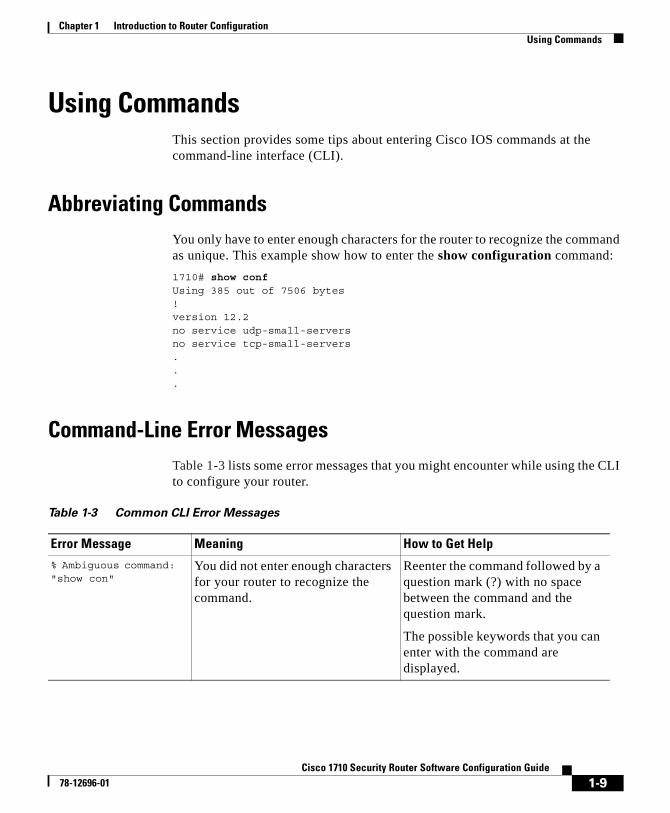
Using CommandsThis section provides some tips about entering Cisco IOS commands at the command-line interface (CLI).
Abbreviating CommandsYou only have to enter enough characters for the router to recognize the command as unique. This example show how to enter the show configuration command:
1710# show confUsing 385 out of 7506 bytes!version 12.2no service udp-small-serversno service tcp-small-servers...
Command-Line Error MessagesTable 1-3 lists some error messages that you might encounter while using the CLI to configure your router.
Table 1-3 Common CLI Error Messages
Error Message Meaning How to Get Help
% Ambiguous command: "show con"
You did not enter enough characters for your router to recognize the command.
Reenter the command followed by a question mark (?) with no space between the command and the question mark.
The possible keywords that you can enter with the command are displayed.
1-9Cisco 1710 Security Router Software Configuration Guide
78-12696-01

Chapter 1 Introduction to Router ConfigurationSaving Configuration Changes
Undoing CommandsIf you want to disable a feature or undo a command you entered, you can enter the keyword no before most commands; for example, no ip routing.
Saving Configuration ChangesYou need to enter the copy running-config startup-config command to save your configuration changes to nonvolatile random-access memory (NVRAM) so that they are not lost if there is a system reload or power outage. This example shows how use this command to save your changes:
Router# copy running-config startup-configBuilding configuration...
It might take a minute or two to save the configuration to NVRAM. After the configuration has been saved, the following appears:
[OK]Router#
% Incomplete command. You did not enter all of the keywords or values required by this command.
Reenter the command followed by a question mark (?) with no space between the command and the question mark.
The possible keywords that you can enter with the command are displayed.
% Invalid input detected at ‘^’ marker.
You entered the command incorrectly. The error occurred where the caret mark (^) appears.
Enter a question mark (?).
All of the commands that are available in this command mode are displayed.
Table 1-3 Common CLI Error Messages (continued)
Error Message Meaning How to Get Help
1-10Cisco 1710 Security Router Software Configuration Guide
78-12696-01

Chapter 1 Introduction to Router ConfigurationUsing Debug Commands
Using Debug CommandsDebug command are provided for most of the configurations in this document. You can use the debug commands to troubleshoot any configuration problems that you might be having on your network. Debug commands provide extensive, informative displays to help you interpret any possible problems.
Table 1-4 contains important information about debug commands.
Caution Debugging is assigned a high priority in your router CPU process, and it can render your router unusable. For this reason, use debug commands only to troubleshoot specific problems.The best time to use debug commands is during periods of low network traffic and few users to decrease the likelihood that the debug command processing overhead affects network users.
Table 1-4 Important Information About Debug Commands
What Information
Additional documentation You can find additional information and documentation about the debug commands in the Debug Command Reference document on the Cisco IOS software documentation CD-ROM that came with your router.
If you are not sure where to find this document on the CD-ROM, use the Search function in the Verity Mosaic browser that comes with the CD-ROM.
Disabling debugging To turn off any debugging, enter the undebug all command.
Telnet sessions If you want to use debug commands during a Telnet session with your router, you must first enter the terminal monitor command.
1-11Cisco 1710 Security Router Software Configuration Guide
78-12696-01

Chapter 1 Introduction to Router ConfigurationWhere to Go Next
Where to Go NextNow that you have learned some Cisco IOS software basics, you can begin to configure your router.
Remember that
• You can use the question mark (?) and arrow keys to help you enter commands.
• Each command mode restricts you to a set of commands. If you are having difficulty entering a command, check the prompt, and then enter the question mark (?) for a list of available commands. You might be in the wrong command mode or using the wrong syntax.
• If you want to disable a feature, enter the keyword no before the command; for example, no ip routing.
• You need to save your configuration changes to NVRAM so that they are not lost if there is a system reload or power outage.
1-12Cisco 1710 Security Router Software Configuration Guide
78-12696-01

Cisco 1710 Security Rou78-12696-01
C H A P T E R 2
Cisco 1710 Security Router ConfigurationThis chapter presents basic configuration procedures for features of the Cisco 1710 Security router. For a full description of these features and their configurations, please refer to Cisco IOS Software Configuration: Cisco IOS Release 12.2.
This chapter contains the following sections:
• Before You Configure Your Network
• Configuring a Virtual Private Dialup Network
• Configuring IP Security
• Configuring the Dialer Interface
• Configuring the Ethernet Interfaces
• Configuring Dynamic Host Configuration Protocol
• Configuring Network Address Translation
• Configuring Firewalls
• Complete Sample Configuration
2-1ter Software Configuration Guide

Chapter 2 Cisco 1710 Security Router ConfigurationBefore You Configure Your Network
Before You Configure Your NetworkBefore you configure your network, you must do the following:
• Arrange for a digital subscriber line (DSL) or cable connection with your corporate network or service provider.
• If you are setting up an Internet connection, gather the following information:
– Client name that is assigned as your login name
– Authentication type
– Password for accessing your Internet service provider (ISP) account
– Domain Name System (DNS) server IP address and default gateways
• If you are setting up a connection to a corporate network, you and its network administrator must generate and share the following information for the interfaces of the routers connected to xDSL or cable modems:
– Authentication type
– Client name for accessing the router
– Password for accessing the router
• If you are setting up Internet Protocol (IP) routing, generate the addressing scheme for your IP network.
Configuring a Virtual Private Dialup NetworkComplete the following tasks to configure a virtual private dialup network (VPDN). Start in global configuration mode.
Command Task
Step 1 vpdn enable Enable VPDN.
Step 2 no vpdn logging Disable VPDN logging.
Step 3 vpdn-group tag Configure a VPDN group.
Step 4 request-dialin Specify the dialing direction.
2-2Cisco 1710 Security Router Software Configuration Guide
78-12696-01

Chapter 2 Cisco 1710 Security Router ConfigurationConfiguring IP Security
Configuring IP SecurityIP Security (IPSec) is a framework of open standards for ensuring secure private communications over IP networks. Based on standards developed by the Internet Engineering Task Force (IETF), IPSec ensures confidentiality, integrity, and authenticity of data communications across a public IP network. Cisco’s realization of IPSec implements the Data Encryption Standard (DES) and triple DES (3DES).
Refer to the Cisco IOS Security Configuration Guide, Release 12.1, for more detailed information on IPSec.
Perform the following tasks to configure IPSec. Start in global configuration mode.
Step 5 protocol pppoe Specify the tunneling protocol as PPPoE.
Step 6 end Exit router configuration mode.
Command Task
Command Task
Step 1 crypto isakmp policy 10 Define an Internet Key Exchange (IKE) policy, and assign the policy a priority. This command places the router in IKE policy configuration mode.
Step 2 hash algorithm Specify the hash algorithm for the policy.
Step 3 encryption encryption Specify the encryption for the policy.
Step 4 authentication pre-share Specify pre-share key as the authentication method.
Step 5 exit Exit IKE policy configuration mode.
Step 6 crypto isakmp key name address ip-address Configure a pre-share key and static IP address for each VPN client.
Step 7 crypto ipsec transform-set name esp-encryption esp-hash algorithm-hmac
Define a combination of security associations to occur during IPSec negotiations.
Step 8 crypto mib ipsec flowmib history tunnel size size
Set the size of the tunnel history table.
2-3Cisco 1710 Security Router Software Configuration Guide
78-12696-01

Chapter 2 Cisco 1710 Security Router ConfigurationConfiguring IP Security
Disabling Hardware EncryptionThe Cisco 1710 Security router is equipped with a Virtual Private Network (VPN) module that provides hardware 3DES encryption by default. It is possible to disable the VPN module and use Cisco IOS software encryption/decryption instead.
The command which disables the VPN module is as follows:
no crypto engine accelerator
The command is executed in configuration mode. An example of its use is as follows:
c1710(config)#no crypto engine accelerator Warning! all current connections will be torn down.Do you want to continue? [yes/no]: yes .Crypto accelerator in slot 0 disabled.switching to IPsec crypto engine
Step 9 crypto mib ipsec flowmib history failure size size
Set the size of the failure history table.
Step 10 crypto map name local-address Ethernet 0 Specify and name an identifying interface to be used by the crypto map for IPSec traffic
Step 11 crypto map name seq-num ipsec-isakmp Create a crypto map entry in IPSec ISAKMP mode, and enter crypto map configuration mode.
Step 12 set peer ip-address Identify the remote IPSec peer.
Step 13 set transform-set name Specify the transform set to be used.
Step 14 set pfs [group1|group2] Specify use of the perfect forward secrecy (pfs) option in IPSec. The variation group1 is default.
Step 15 match address access-list-id Specify an extended access list for the crypto map entry.
Step 16 exit Exit crypto map configuration mode.
Command Task
2-4Cisco 1710 Security Router Software Configuration Guide
78-12696-01

Chapter 2 Cisco 1710 Security Router ConfigurationConfiguring IP Security
After this command is executed, it is necessary to perform the following procedures to bring up all encryption tunnels appropriately.
Step 1 On all involved routers, shut down the interfaces that have crypto maps applied to them.
Step 2 Enter the following commands on each of the involved routers.
Step 3 Bring up the interfaces on all involved routers that were shut down in Step 1.
To re-enable the VPN module, use the following command:
crypto engine accelerator
An example of its use is as follows:
c1710(config)#crypto engine accelerator Warning! all current connections will be torn down. Do you want to continue? [yes|no]:yes . switching to crypto accelerator.
The following is a useful command that shows statistical information about the VPN module:
show crypto engine accelerator statistic
An example of its use is as follows:
c1710#show crypto engine accelerator statistic C1700_EM: ds: 0x81784BA4 idb:0x81780560
Command Task
clear crypto sa Clears the security associations applied to the router.
clear crypto isakmp Clears the active IKE connections to the router.
show crypto engine connections active Lists the active connections. In this scenario, it verifies that no connections are active. It may be necessary to repeat these commands until no connections are listed.
2-5Cisco 1710 Security Router Software Configuration Guide
78-12696-01
Chapter 2 Cisco 1710 Security Router ConfigurationConfiguring the Dialer Interface
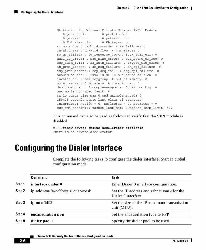
Statistics for Virtual Private Network (VPN) Module: 0 packets in 0 packets out 0 paks/sec in 0 paks/sec out 0 Kbits/sec in 0 Kbits/sec out rx_no_endp: 0 rx_hi_discards: 0 fw_failure: 0 invalid_sa: 0 invalid_flow: 0 cgx_errors 0 fw_qs_filled: 0 fw_resource_lock:0 lotx_full_err: 0 null_ip_error: 0 pad_size_error: 0 out_bound_dh_acc: 0 esp_auth_fail: 0 ah_auth_failure: 0 crypto_pad_error: 0 ah_prot_absent: 0 ah_seq_failure: 0 ah_spi_failure: 0 esp_prot_absent:0 esp_seq_fail: 0 esp_spi_failure: 0 obound_sa_acc: 0 invalid_sa: 0 out_bound_sa_flow: 0 invalid_dh: 0 bad_keygroup: 0 out_of_memory: 0 no_sh_secret: 0 no_skeys: 0 invalid_cmd: 0 dsp_coproc_err: 0 comp_unsupported:0 pak_too_big: 0 pak_mp_length_spec_fault: 0 tx_lo_queue_size_max 0 cmd_unimplemented: 0 159405 seconds since last clear of counters Interrupts: Notify = 0, Reflected = 0, Spurious = 0 cgx_cmd_pending:0 packet_loop_max: 0 packet_loop_limit: 512
This command can also be used as follows to verify that the VPN module is disabled:
c1710#show crypto engine accelerator statistic There is no crypto accelerator.
Configuring the Dialer InterfaceComplete the following tasks to configure the dialer interface. Start in global configuration mode.
Command Task
Step 1 interface dialer 0 Enter Dialer 0 interface configuration.
Step 2 ip address ip-address subnet-mask Set the IP address and subnet mask for the Dialer 0 interface.
Step 3 ip mtu 1492 Set the size of the IP maximum transmission unit (MTU).
Step 4 encapsulation ppp Set the encapsulation type to PPP.
Step 5 dialer pool 1 Specify the dialer pool to be used.
2-6Cisco 1710 Security Router Software Configuration Guide
78-12696-01

Chapter 2 Cisco 1710 Security Router ConfigurationConfiguring the Ethernet Interfaces
Configuring the Ethernet InterfacesConfigure the Ethernet interfaces by performing the following tasks. Begin in the global configuration mode.
Step 6 dialer-group 1 Assign this interface to a dialer list.
Step 7 ppp authentication chap Optional. Set the PPP authentication method to Challenge Handshake Authentication Protocol (CHAP).
Step 8 exit Exit Dialer 0 interface configuration.
Command Task
Command Task
Step 1 interface Ethernet 0 Configure the Ethernet interface.
Step 2 ip address ip-address subnet-mask Set the IP address and subnet mask for the Ethernet 0 interface.
Step 3 ip nat outside Optional. Establish the Ethernet interface as the outside interface.
Step 4 exit Exit Ethernet 0 interface configuration.
Step 5 crypto map name Apply crypto map to the Ethernet interface.
Step 6 interface FastEthernet 0 Configure the Fast Ethernet interface.
Step 7 ip address ip-address subnet-mask Set the IP address and subnet mask for the Fast Ethernet interface.
Step 8 ip nat inside Optional. Establish the Fast Ethernet interface as the inside interface.
Step 9 pppoe enable Optional. Enable PPPoE as protocol.
Step 10 pppoe-client dial-pool-number 1 Optional. Create the PPPoE dial pool.
Step 11 exit Exit Fast Ethernet 0 interface configuration.
2-7Cisco 1710 Security Router Software Configuration Guide
78-12696-01

Chapter 2 Cisco 1710 Security Router ConfigurationConfiguring Dynamic Host Configuration Protocol
Configuring Dynamic Host Configuration ProtocolThe Dynamic Host Configuration Protocol (DHCP) is used to enable hosts (DHCP clients) on an IP network to obtain their configurations from a server (DHCP server). This reduces the work necessary to administer an IP network. The most significant configuration option the client receives from the server is its IP address.
Perform the following tasks to configure DHCP. Begin in global configuration mode.
Configuration ExampleIn the following example, three DHCP address pools are created: one in network 172.16.0.0, one in subnetwork 172.16.1.0, and one in subnetwork 172.16.2.0. Attributes from network 172.16.0.0, such as the domain name, DNS server, NetBIOS name server, and NetBIOS node type, are inherited in subnetworks
Command Task
Step 1 ip dhcp excluded-address low-ip-address high-ip-address
Prevent DHCP from assigning one or more IP addresses to potential clients.
Step 2 ip dhcp pool name Enter DHCP configuration mode, and create a pool of IP addresses that can be assigned to DHCP clients.
Step 3 network address subnet-mask Specify a range of IP addresses that can be assigned to the DHCP clients.
Step 4 default-router ip-address Specify the default router.
Step 5 domain-name domain name Specify the domain name.
Step 6 dns-server ip-address Specify the DNS server.
Step 7 netbios-name-server ip-address Specify the NetBIOS name server.
Step 8 netbios-node-type node-type Specify the NetBIOS node type.
Step 9 lease dayslease infinite
Specify the duration of the lease.
2-8Cisco 1710 Security Router Software Configuration Guide
78-12696-01

Chapter 2 Cisco 1710 Security Router ConfigurationConfiguring Dynamic Host Configuration Protocol
172.16.1.0 and 172.16.2.0. In each pool, clients are granted 30-day leases and all addresses in each subnetwork, except the excluded addresses, are available to the DHCP server for assigning to clients.
ip dhcp database ftp://user:[email protected]/router-dhcp write-delay 120ip dhcp excluded-address 172.16.1.100 172.16.1.103 ip dhcp excluded-address 172.16.2.100 172.16.2.103!ip dhcp pool 0 network 172.16.0.0 /16 domain-name cisco.com dns-server 172.16.1.102 172.16.2.102 netbios-name-server 172.16.1.103 172.16.2.103 netbios-node-type h-node!ip dhcp pool 1 network 172.16.1.0 /24 default-router 172.16.1.100 172.16.1.101 lease 30 !ip dhcp pool 2 network 172.16.2.0 /24 default-router 172.16.2.100 172.16.2.101 lease 30
Manual Binding Configuration ExampleThe following example creates a manual binding for a client named Mars.cisco.com. The MAC address of the client is 02c7.f800.0422 and the IP address of the client is 172.16.2.254.
ip dhcp pool Mars host 172.16.2.254 hardware-address 02c7.f800.0422 ieee802 client-name Mars
Because attributes are inherited, the previous configuration is equivalent to the following:
ip dhcp pool Mars host 172.16.2.254 mask 255.255.255.0 hardware-address 02c7.f800.0422 ieee802 client-name Mars default-router 172.16.2.100 172.16.2.101 domain-name cisco.com
2-9Cisco 1710 Security Router Software Configuration Guide
78-12696-01

Chapter 2 Cisco 1710 Security Router ConfigurationConfiguring Network Address Translation
dns-server 172.16.1.102 172.16.2.102 netbios-name-server 172.16.1.103 172.16.2.103 netbios-node-type h-node
Configuring Network Address TranslationNetwork Address Translation (NAT) translates IP addresses within private “internal” networks to “legal” IP addresses for transport over public “external” networks (such as the Internet). Incoming traffic is translated back for delivery within the inside network. Thus, NAT allows an organization with unregistered “private” addresses to connect to the Internet by translating those addresses into globally registered IP addresses.
Ethernet interfaces are configured as “NAT inside” or “NAT outside” as shown in the previous section “Configuring the Ethernet Interfaces.” Once the interfaces are configured, the following steps can be performed to establish the NAT configuration within the router.
Command Task
Step 1 ip nat pool name start-ip end-ip {netmask netmask | prefix-length prefix-length}
Create a pool of global IP addresses for NAT.
Step 2 access-list access-list-number permit source [source-wildcard]
Define a standard access list permitting addresses that need translation.
Step 3 ip nat inside source list access-list-number pool name [overload]
Enable dynamic translation of addresses permitted by access list. Overload allows the use of one global address, from the pool, for many local addresses.
Step 4 ip nat outside source static global-ip local-ip
Enable static translation of a specified outside source address. This command is optional.
2-10Cisco 1710 Security Router Software Configuration Guide
78-12696-01

Chapter 2 Cisco 1710 Security Router ConfigurationConfiguring Network Address Translation
Configuration ExampleIn this example, we want NAT to allow certain devices on the inside to originate communication with devices on the outside by translating their internal addresses to valid outside addresses or a pool of addresses. The pool in this example is defined as the range of addresses 172.16.10.1 through 172.16.10.63.
In order to accomplish this translation, we need to use dynamic NAT. With dynamic NAT, the translation table in the router is initially empty and gets populated once traffic that needs to be translated passes through the router. (This is opposed to static NAT, in which a translation is statically configured and is placed in the translation table without the need for any traffic.)
In this example, we can configure NAT to translate each inside device address to a unique valid outside address, or to translate each inside device address to the same valid outside address. The second method is known as overloading. An example of how to configure each method is given here.
To begin, configure the Fast Ethernet interface with an IP address and as a “NAT inside” interface.
interface FastEthernet 0 ip address 10.10.10.1 255.255.255.0 ip nat inside
Then configure the Ethernet interface with an IP address and as a “NAT outside” interface.
interface Ethernet 0 ip address 172.16.10.64 255.255.255.0 ip nat outside
To handle the case in which each inside address is translated to its own unique outside address, define a NAT pool named “no-overload” with a range of addresses from 172.16.10.0 to 172.16.10.63
ip nat pool no-overload 172.16.10.0 172.16.10.63 prefix 24
Define access list 7 to permit packets with source addresses ranging from 10.10.10.0 through 10.10.10.31 and from 10.10.20.0 through 10.10.20.31.
access-list 7 permit 10.10.10.0 0.0.0.31access-list 7 permit 10.10.20.0 0.0.0.31
2-11Cisco 1710 Security Router Software Configuration Guide
78-12696-01
Chapter 2 Cisco 1710 Security Router ConfigurationConfiguring Firewalls
Then indicate that any packet received on the inside interface, as permitted by access list 7, will have its source address translated to an address from the NAT pool “no-overload.”
ip nat inside source list 7 pool no-overload
Alternatively, to handle the case where all inside addresses are translated to a single outside address, define a NAT pool named “ovrld,” which has a range of a single IP address: 172.16.10.1.
ip nat pool ovrld 172.16.10.1 172.16.10.1 prefix 24
Then indicate that any packet received on the inside interface, as permitted by access list 7, will have its source address translated to the address from the NAT pool “ovrld.” Translations will be overloaded, which will allow multiple inside devices to be translated to the same outside IP address.
ip nat inside source list 7 pool ovrld overload
The keyword overload used in this command allows NAT to translate multiple inside devices to the single address in the pool.
Another variation of this command is ip nat inside source list 7 interface Ethernet 0 overload, which configures NAT to overload on the address that is assigned to the Ethernet 0 interface.
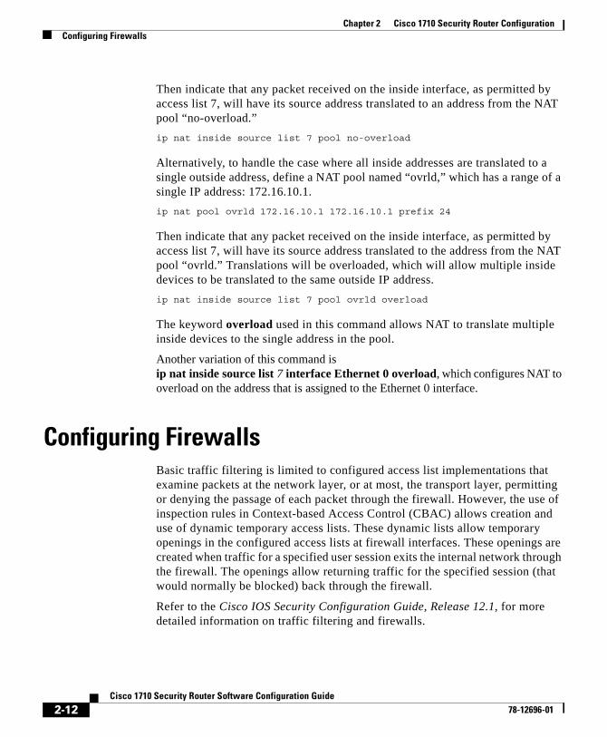
Configuring FirewallsBasic traffic filtering is limited to configured access list implementations that examine packets at the network layer, or at most, the transport layer, permitting or denying the passage of each packet through the firewall. However, the use of inspection rules in Context-based Access Control (CBAC) allows creation and use of dynamic temporary access lists. These dynamic lists allow temporary openings in the configured access lists at firewall interfaces. These openings are created when traffic for a specified user session exits the internal network through the firewall. The openings allow returning traffic for the specified session (that would normally be blocked) back through the firewall.
Refer to the Cisco IOS Security Configuration Guide, Release 12.1, for more detailed information on traffic filtering and firewalls.
2-12Cisco 1710 Security Router Software Configuration Guide
78-12696-01

Chapter 2 Cisco 1710 Security Router ConfigurationConfiguring Firewalls
Access ListsAccess lists are configured as standard or extended. A standard access list either permits or denies passage of packets from a designated source. An extended access list allows designation of both the destination and the source, and it allows designation of individual protocols to be permitted or denied passage. An access list is a series of commands with a common tag to bind them together. The tag is either a number or a name.
Standard numbered access list commands take the following form:
access-list {1-99} {permit|deny} source-addr [source-mask]
Extended numbered access list commands take the following form:
access-list {100-199} {permit|deny} protocol source-addr [source-mask] destination-addr [destination-mask]
Named access list commands take the form:
ip access-list {standard|extended} name
A standard named access list command must be followed by subcommands in this form:
deny {source|source-wildcard|any}
An extended named access list command must be followed by a subcommand in this form:
{permit|deny} protocol {source-addr[source-mask]|any} {destination-addr [destination-mask]|any}
A sequence of access list commands bound together with a common name or number is referred to as an access group. An access group is enabled for an interface during interface configuration with the command
ip access-group number|name [in|out]
where in|out refers to the direction of travel of the packets being filtered.
When a sequence of access list commands is used, three things must be kept in mind:
• The order of commands in the sequence is important. A packet will be operated on by the first command. If there is no match (neither a permit nor a deny occurs), the next command operates on the packet, and so on.
2-13Cisco 1710 Security Router Software Configuration Guide
78-12696-01

Chapter 2 Cisco 1710 Security Router ConfigurationConfiguring Firewalls
• All matching parameters must be true before a command permits or denies access to a packet.
• There is an implicit “deny all” at the end of the sequence.
Configuration Examples
The following examples illustrate the configuration of standard numbered access lists and extended numbered access lists.
Configuring Standard Numbered Access Lists
In the following example, access list 2, a standard numbered access list, is defined to operate on the router, permitting or denying passage of packets associated with network 36.0.0.0. This network is a Class A network whose second octet specifies a subnet; that is, its subnet mask is 255.255.0.0. The third and fourth octets of a network 36.0.0.0 address specify a particular host. Using access list 2, the router would accept one address on subnet 48 and reject all others on that subnet. The last line of the list shows that the router would accept addresses on all other network 36.0.0.0 subnets.
access-list 2 permit 36.48.0.3access-list 2 deny 36.48.0.0 0.0.255.255 access-list 2 permit 36.0.0.0 0.255.255.255
Note that all other accesses are implicitly denied.
The following commands tie the access group to a specific interface on the router, and specify that incoming packets are to be permitted or denied passage:
interface ethernet 0 ip access-group 2 in
Configuring Extended Numbered Access Lists
In the following example, access list 102, an extended numbered access list, is defined. The first command permits any incoming TCP messages with destination ports greater than 1023. The second command permits incoming TCP messages to the SMTP port of host 128.88.1.2. The third command permits incoming ICMP messages for error feedback.
access-list 102 permit tcp 0.0.0.0 255.255.255.255 128.88.0.0 0.0.255.255 gt 1023access-list 102 permit tcp 0.0.0.0 255.255.255.255 128.88.1.2 0.0.0.0 eq 25access-list 102 permit icmp 0.0.0.0 255.255.255.255 128.88.0.0 255.255.255.255
2-14Cisco 1710 Security Router Software Configuration Guide
78-12696-01

Chapter 2 Cisco 1710 Security Router ConfigurationComplete Sample Configuration
The following commands tie the access group to a specific interface on the router and specify that incoming packets are to be permitted or denied passage:
interface ethernet 0 ip access-group 102 in
Inspection RulesSpecify which protocols to examine by using the ip inspect name command. When inspection detects that the specified protocol is passing through the firewall, a dynamic access list is created to allow the passage of return traffic. The timeout parameter specifies the length of time the dynamic access list will remain active without return traffic passing through the router. When a timeout is reached, the dynamic access list is removed, and subsequent packets (possibly even valid ones) are not permitted.
For each protocol you want to inspect, enter a line in global configuration mode using the following syntax:
ip inspect name inspection-name protocol timeout seconds
Use the same inspection-name in multiple statements to group them into one set of rules. This set of rules can be activated elsewhere in the configuration by using the ip inspect inspection-name in|out command when configuring an interface at the firewall.
Complete Sample ConfigurationAn example configuration is presented here, in which a Cisco 1710 Security router is a PPPoE client connected through a modem to an external network access router. The router might be located in a branch office with the network access router located at the corporate site. One alternate scenario could be that the router is in a small or medium business, and the network access router belongs to a service provider. In each case, the network access router provides a dial-in data service with secure tunnels to the business or branch office for mobile users.
This example presents a full configuration of the Cisco 1710 Security router, along with a complementary configuration of IPSec on the network access router.
2-15Cisco 1710 Security Router Software Configuration Guide
78-12696-01

Chapter 2 Cisco 1710 Security Router ConfigurationComplete Sample Configuration
In this example, both the Cisco 1710 Security router and the network access router have inside and outside interfaces. The outside interfaces have global IP addresses while the inside interfaces have local IP addresses. These addresses are as follows:
• Cisco 1710 Security router outside interface: 24.119.216.150 255.255.255.0
• Cisco 1710 Security router inside interface: 192.168.1.0 255.255.255.0
• Network access router outside interface: 16.0.0.2 255.0.0.0
• Network access router inside interface: 172.28.0.1 255.255.0.0
The outside interface of the router in this example is the Ethernet port, while the inside interface is the Fast Ethernet port.
Figure 2-1 illustrates the topology of this example.
Figure 2-1 Configuration Example
Networkaccessserver
1710 with IPSECdoing PPPoEon Ethernet
DSL
Ethernet
Fast Ethernet
DSLAM/access
concentrator CPE providedby carrier
IP/ATM
6025
5
2-16Cisco 1710 Security Router Software Configuration Guide
78-12696-01

Chapter 2 Cisco 1710 Security Router ConfigurationComplete Sample Configuration
Cisco 1710 Security Router ConfigurationThe following commands configure the router so that it provides a secure connection to the network access router.
ip domain-name cisco.comip name-server 24.1.64.33ip name-server 24.1.64.34ip dhcp excluded-address 192.168.1.1 192.168.1.5!ip dhcp pool home-poolnetwork 192.168.1.0 255.255.255.0default-router 192.168.1.1domain-name cisco.comdns-server 24.1.64.34!ip inspect name fw_all ftpip inspect name fw_all http java-list 10ip inspect name fw_all rcmdip inspect name fw_all rpc program-number 100000ip inspect name fw_all smtpip inspect name fw_all tftpip inspect name fw_all realaudioip inspect name fw_all streamworksip inspect name fw_all vdoliveip inspect name fw_all cuseemeip inspect name fw_all h323ip inspect name fw_all tcpip inspect name fw_all udpip audit notify logip audit po max-events 100!vpdn enableno vpdn logging!vpdn-group 1request-dialinprotocol pppoe!crypto isakmp key 12abcjhrweit345 address 16.0.0.2!crypto isakmp policy 1authentication pre-shareencryption 3deshash shagroup 2!crypto ipsec transform-set proposal1 esp-3des esp-sha-hmac ah-sha-hmac
2-17Cisco 1710 Security Router Software Configuration Guide
78-12696-01

Chapter 2 Cisco 1710 Security Router ConfigurationComplete Sample Configuration
!crypto map tag local-address Ethernet0crypto map tag 10 ipsec-isakmpset peer 16.0.0.2set security-association level per-hostset transform-set proposal1set pfs group2match address 100!interface Dialer0ip unnumbered Ethernet0no ip route-cacheencapsulation pppip mtu 1492dialer pool 1dialer-group 1ip nat outsideip inspect fw_all inip access-group 102 incrypto map tag!interface FastEthernet0ip address 192.168.1.1 255.255.255.0ip nat inside!interface Ethernet0ip address 24.19.216.150 255.255.255.0pppoe enablepppoe-client dial-pool-number 1crypto map tag!dialer-list 1 protocol ip permit!access-list 100 permit 192.168.1.0 0.255.255.255!ip nat inside source list homenet interface Ethernet0 overloadip nat outside source static 24.19.216.129 192.168.1.5!ip access-list extended homenet permit ip 192.168.1.0 0.255.255.255 any!access-list 102 deny tcp any anyaccess-list 102 permit esp any anyaccess-list 102 permit ahp any anyaccess-list 102 permit udp any eq isakmp any eq isakmpaccess-list 102 deny udp any anyaccess-list 102 permit ip any anyaccess-list 102 permit icmp any any
2-18Cisco 1710 Security Router Software Configuration Guide
78-12696-01

Chapter 2 Cisco 1710 Security Router ConfigurationComplete Sample Configuration
Network Access Router ConfigurationThe following commands configure the network access router so that it provides a secure connection to the Cisco 1710 Security router.
crypto isakmp key 12abcjhrweit345 address 24.19.216.150!crypto isakmp policy 1authentication pre-shareencryption 3deshash shagroup 2!crypto ipsec transform-set proposal1 esp-3des esp-sha-hmac ah-sha-hmac!crypto map mymap1 local-address FastEthernet0/1crypto map tag 10 ipsec-isakmpset peer 24.19.216.150set security-association level per-hostset transform-set proposal1set pfs group2match address 100!access-list 100 permit 172.28.0.0 0.0.255.255!interface FastEthernet0/1ip address 16.0.0.2 255.0.0.0crypto map tag!interface FastEthernet0/0ip address 172.28.0.1 255.255.0.0
2-19Cisco 1710 Security Router Software Configuration Guide
78-12696-01

Chapter 2 Cisco 1710 Security Router ConfigurationComplete Sample Configuration
2-20Cisco 1710 Security Router Software Configuration Guide
78-12696-01

Cisco 1710 Security Rou78-12696-01
C H A P T E R 3
Overview of Routing Between Virtual LANsThis chapter provides an overview of virtual LANs (VLANs). It describes the encapsulation protocols used for routing between VLANs and provides some basic information about designing VLANs.
This chapter contains the following sections:
• What Is a VLAN?
• VLAN Colors
• Why Implement VLANs?
• Communicating Between VLANs
• Designing Switched VLANs
What Is a VLAN?A VLAN is a switched network that is logically segmented on an organizational basis, by function, project team, or application, rather than on a physical or geographical basis. For example, all workstations and servers used by a particular workgroup team can be connected to the same VLAN, regardless of their physical connections to the network or their intermingling with other teams. The network can be reconfigured by using software rather than by physically unplugging and moving the devices or wires.
3-1ter Software Configuration Guide

Chapter 3 Overview of Routing Between Virtual LANsWhat Is a VLAN?
A VLAN can be thought of as a broadcast domain that exists within a defined set of switches. A VLAN consists of a number of end systems, either hosts or network equipment (such as bridges and routers), connected by a single bridging domain. The bridging domain is supported on various pieces of network equipment; for example, LAN switches that operate bridging protocols between them with a separate bridge group for each VLAN.
VLANs are created to provide the segmentation services traditionally provided by routers in LAN configurations. VLANs address scalability, security, and network management. Routers in VLAN topologies provide broadcast filtering, security, address summarization, and traffic flow management. None of the switches within the defined group will bridge any frames, not even broadcast frames, between two VLANs. Several key issues need to be considered when designing and building switched LAN internetworks:
• LAN Segmentation
• Security
• Broadcast Control
• Performance
• Network Management
• Communication Between VLANs
LAN SegmentationVLANs allow logical network topologies to be overlaid onto the physical switched infrastructure such that any arbitrary collection of LAN ports can be combined into an autonomous user group or community of interest. The technology logically segments the network into separate Layer 2 broadcast domains whereby packets are switched between ports designated to be within the same VLAN. By containing traffic originating on a particular LAN only to other LANs in the same VLAN, switched virtual networks avoid wasting bandwidth, a drawback inherent to traditional bridged and switched networks in which packets are often forwarded to LANs with no need for them. Implementation of VLANs also improves scalability, particularly in LAN environments that support broadcast- or multicast-intensive protocols and applications that flood packets throughout the network.
Figure 3-1 illustrates the difference between traditional physical LAN segmentation and logical VLAN segmentation.
3-2Cisco 1710 Security Router Software Configuration Guide
78-12696-01

Chapter 3 Overview of Routing Between Virtual LANsWhat Is a VLAN?
Figure 3-1 LAN Segmentation and VLAN Segmentation
SecurityVLANs also improve security by isolating groups. High-security users can be grouped into a VLAN, possibly on the same physical segment, and no users outside that VLAN can communicate with them.
Broadcast ControlJust as switches isolate collision domains for attached hosts and only forward appropriate traffic out a particular port, VLANs provide complete isolation between VLANs. A VLAN is a bridging domain; all broadcast and multicast traffic is contained within the VLAN.
CatalystVLAN switch
VLAN 1
VLAN segmentationTraditional LAN segmentation
VLAN 2 VLAN 3
LAN 1
Shared hub
Shared hub
Shared hub
Floor 3
Floor 2
Floor 1
LAN 2
LAN 3
S66
19
CatalystVLAN switch
CatalystVLAN switch
Router
Router
3-3Cisco 1710 Security Router Software Configuration Guide
78-12696-01

Chapter 3 Overview of Routing Between Virtual LANsVLAN Colors
PerformanceThe logical grouping of users allows an accounting group to make intensive use of a networked accounting system assigned to a VLAN that contains just that accounting group and its servers. That group’s work will not affect other users. The VLAN configuration improves general network performance by not slowing down other users sharing the network.
Network ManagementThe logical grouping of users allows easier network management. It is not necessary to pull cables to move a user from one network to another. Adds, moves, and changes are achieved by configuring a port into the appropriate VLAN.
Communication Between VLANsCommunication between VLANs is accomplished through routing, and the traditional security and filtering functions of the router can be used. Cisco IOS software provides network services such as security filtering, quality of service (QoS), and accounting on a per VLAN basis. As switched networks evolve to distributed VLANs, Cisco IOS provides key inter-VLAN communications and allows the network to scale.
VLAN ColorsVLAN switching is accomplished through frame tagging, in which traffic originating and contained within a particular virtual topology carries a unique VLAN identifier (VLAN ID) as it traverses a common backbone or trunk link. The VLAN ID enables VLAN switching devices to make intelligent forwarding decisions based on the embedded VLAN ID. Each VLAN is differentiated by a color, or VLAN identifier. The unique VLAN ID determines the frame coloring for the VLAN. Packets originating and contained within a particular VLAN carry the identifier that uniquely defines that VLAN (by the VLAN ID).
3-4Cisco 1710 Security Router Software Configuration Guide
78-12696-01
Chapter 3 Overview of Routing Between Virtual LANsWhy Implement VLANs?
The VLAN ID allows VLAN switches and routers to selectively forward packets to ports with the same VLAN ID. The switch that receives the frame from the source station inserts the VLAN ID, and the packet is switched onto the shared backbone network. When the frame exits the switched LAN, a switch strips the header and forwards the frame to interfaces that match the VLAN color. If you are using a Cisco network management product such as VlanDirector, you can actually color-code the VLANs and monitor VLAN graphically.
Why Implement VLANs?Network managers can group logically networks that span all major topologies, including high-speed technologies such as, ATM, FDDI, and Fast Ethernet. By creating virtual LANs, system and network administrators can control traffic patterns and react quickly to relocations and keep up with constant changes in the network due to moving requirements and node relocation just by changing the VLAN member list in the router configuration. They can add, remove, or move devices or make other changes to network configuration using software to make the changes.
You should consider both the advantages and disadvantages of creating VLANs when you design your network, including these issues:
• Scalability
• Performance improvements
• Security
• Network additions, moves, and changes
Communicating Between VLANsThe Cisco 1710 Security router uses the IEEE 802.1Q protocol for routing between VLANs.
The IEEE 802.1Q protocol is used to interconnect multiple switches and routers and for defining VLAN topologies. IEEE 802.1Q support is currently available only for Fast Ethernet interfaces.
3-5Cisco 1710 Security Router Software Configuration Guide
78-12696-01

Chapter 3 Overview of Routing Between Virtual LANsDesigning Switched VLANs
Procedures for configuring routing between VLANs with IEEE 802.1Q encapsulation are provided in the “Configuring Routing Between VLANs with IEEE 802.1Q Encapsulation” chapter later in this publication.
VLAN TranslationVLAN translation refers to the ability of the Cisco IOS software to translate between different virtual LANs or between VLAN and non-VLAN encapsulating interfaces at Layer 2. Translation is typically used for selective inter-VLAN switching of non-routable protocols and to extend a single VLAN topology across hybrid switching environments. It is also possible to bridge VLANs on the main interface; the VLAN encapsulating header is preserved. Topology changes in one VLAN domain do not affect a different VLAN.
Designing Switched VLANsBy the time you are ready to configure routing between VLANs, you will have already defined them through the switches in your network. Issues related to network design and VLAN definition should be addressed during your network design. Refer to the Cisco Internetworking Design Guide and appropriate switch documentation for information on these topics:
• Sharing resources between VLANs
• Load balancing
• Redundant links
• Addressing
• Segmenting networks with VLANs
• Routers and their role in switched networks
3-6Cisco 1710 Security Router Software Configuration Guide
78-12696-01

Cisco 1710 Security Rou78-12696-01
C H A P T E R 4
Configuring Routing Between VLANs with IEEE 802.1Q EncapsulationThis chapter describes the required and optional tasks for configuring routing between VLANs with IEEE 802.1Q encapsulation. For complete descriptions of the VLAN commands used in this chapter, refer to the “Cisco IOS Switching Commands” chapter in the Cisco IOS Switching Services Command Reference. For documentation of other commands that appear in this chapter, you can either use the command reference master index or search online.
The IEEE 802.1Q protocol is used to interconnect multiple switches and routers and for defining VLAN topologies. IEEE 802.1Q support is currently available for Fast Ethernet interfaces.
Note The Cisco 1710 Security router supports IEEE 802.1Q only on the Fast Ethernet interface.
IEEE 802.1Q Encapsulation Configuration Task ListYou can configure routing between any number of VLANs in your network. This section documents the configuration tasks for each protocol supported with IEEE 802.1Q encapsulation. The basic process is the same, regardless of the protocol being routed. It involves:
• Enabling the protocol on the router
• Enabling the protocol on the interface
4-1ter Software Configuration Guide

Chapter 4 Configuring Routing Between VLANs with IEEE 802.1Q EncapsulationIEEE 802.1Q Encapsulation Configuration Task List
• Defining the encapsulation format as IEEE 802.1Q
• Customizing the protocol according to the requirements for your environment
The configuration processes documented in this chapter include the following:
• Configuring AppleTalk Routing over IEEE 802.1Q
• Configuring IP Routing over IEEE 802.1Q
• Configuring IPX Routing over IEEE 802.1Q
Configuring AppleTalk Routing over IEEE 802.1Q AppleTalk can be routed over virtual LAN (VLAN) subinterfaces, using the IEEE 802.1Q VLAN encapsulation protocol. AppleTalk Routing provides full-feature Cisco IOS software AppleTalk support on a per VLAN basis, allowing standard AppleTalk capabilities to be configured on VLANs.
To route AppleTalk over IEEE 802.1Q between VLANs, you need to customize the subinterface to create the environment in which it will be used. Perform these tasks in the order in which they appear:
• Enabling AppleTalk Routing
• Defining the VLAN Encapsulation Format
• Configuring AppleTalk on the Subinterface
Enabling AppleTalk Routing
To enable AppleTalk routing on IEEE 802.1Q interfaces, use the following command in global configuration mode:
Note For more information on configuring AppleTalk, see the “Configuring AppleTalk” chapter in the Cisco IOS AppleTalk and Novell IPX Configuration Guide.
Command Purposeappletalk routing [eigrp router-number] Enables AppleTalk routing globally.
4-2Cisco 1710 Security Router Software Configuration Guide
78-12696-01

Chapter 4 Configuring Routing Between VLANs with IEEE 802.1Q EncapsulationIEEE 802.1Q Encapsulation Configuration Task List
Configuring AppleTalk on the Subinterface
After you enable AppleTalk globally and define the encapsulation format, you need to enable it on the subinterface by specifying the cable range and naming the AppleTalk zone for each interface. To enable the AppleTalk protocol on the subinterface, use the following commands in interface configuration mode:
Defining the VLAN Encapsulation Format
To define the VLAN encapsulation format as IEEE 802.1Q, use the following commands in interface configuration mode:
Configuring IP Routing over IEEE 802.1QIP routing over IEEE 802.1Q extends IP routing capabilities to include support for routing IP frame types in VLAN configurations using the IEEE 802.1Q encapsulation.
Command Purpose
Step 1 appletalk cable-range cable-range [network.node] Assigns the AppleTalk cable range and zone for the subinterface.
Step 2 appletalk zone zone-name Assigns the AppleTalk zone for the subinterface.
Command Purpose
Step 1 interface fastethernet port.subinterface-number Specifies the subinterface that the VLAN will use.
Step 2 encapsulation dot1q vlan-identifier Defines the encapsulation format as IEEE 802.1Q (dot1q) and specifies the VLAN identifier.
4-3Cisco 1710 Security Router Software Configuration Guide
78-12696-01

Chapter 4 Configuring Routing Between VLANs with IEEE 802.1Q EncapsulationIEEE 802.1Q Encapsulation Configuration Task List
To route IP over IEEE 802.1Q between VLANs, you need to customize the subinterface to create the environment in which it will be used. Perform these tasks in the order in which they appear:
• Enabling IP Routing
• Defining the VLAN Encapsulation Format
• Assigning an IP Address to a Network Interface
Enabling IP Routing
IP routing is automatically enabled in the Cisco IOS software for routers. To re-enable IP routing if it has been disabled, use the following command in global configuration mode:
Once you have IP routing enabled on the router, you can customize the characteristics to suit your environment. If necessary, refer to the IP configuration chapters in the Cisco IOS IP and IP Routing Configuration Guide for guidelines on configuring IP.
Defining the VLAN Encapsulation Format
To define the encapsulation format as IEEE 802.1Q, use the following commands in interface configuration mode:
Command Purposeip routing Enables IP routing on the router.
Command Purpose
Step 1 interface fastethernet port.subinterface-number
Specifies the subinterface on which IEEE 802.1Q will be used.
Step 2 encapsulation dot1q vlanid Defines the encapsulation format as IEEE 802.1Q (dot1q) and specifies the VLAN identifier.
4-4Cisco 1710 Security Router Software Configuration Guide
78-12696-01

Chapter 4 Configuring Routing Between VLANs with IEEE 802.1Q EncapsulationIEEE 802.1Q Encapsulation Configuration Task List
Assigning an IP Address to a Network Interface
An interface can have one primary IP address. To assign a primary IP address and a network mask to a network interface, use the following command in interface configuration mode:
A mask identifies the bits that denote the network number in an IP address. When you use the mask to subnet a network, the mask is then referred to as a subnet mask.
Configuring IPX Routing over IEEE 802.1QIPX Routing over IEEE 802.1Q VLANs extends Novell NetWare routing capabilities to include support for routing Novell Ethernet_802.3 encapsulation frame types in VLAN configurations. Users with Novell NetWare environments can configure Novell Ethernet_802.3 encapsulation frames to be routed using IEEE 802.1Q encapsulation across VLAN boundaries.
To configure Cisco IOS software on a router with connected VLANs to exchange IPX Novell Ethernet_802.3 encapsulated frames, perform these tasks in the order in which they are appear:
• Enabling NetWare Routing
• Defining the VLAN Encapsulation Format
• Configuring NetWare on the Subinterface
Enabling NetWare Routing
To enable IPX routing on IEEE 802.1Q interfaces, use the following command in global configuration mode:
Command Purposeip address ip-address mask Sets a primary IP address for an interface.
Command Purposeipx routing [node] Enables IPX routing globally.
4-5Cisco 1710 Security Router Software Configuration Guide
78-12696-01

Chapter 4 Configuring Routing Between VLANs with IEEE 802.1Q EncapsulationExamples of IEEE 802.1Q Encapsulation Configuration
Defining the VLAN Encapsulation Format
To define the encapsulation format as IEEE 802.1Q, use the following commands in interface configuration mode:
Configuring NetWare on the Subinterface
After you enable NetWare globally and define the VLAN encapsulation format, you may need to enable the subinterface by specifying the NetWare network number. Use this command in interface configuration mode:
Examples of IEEE 802.1Q Encapsulation Configuration
This section provides configuration examples for each of the protocols described in this chapter. The section provides the examples for the following:
• Configuring AppleTalk over IEEE 802.1Q
• Configuring IP Routing over IEEE 802.1Q
• Configuring IPX Routing over IEEE 802.1Q
Command Purpose
Step 1 interface fastethernet port.subinterface-number
Specifies the subinterface on which IEEE 802.1Q will be used.
Step 2 encapsulation dot1q vlan-identifier Defines the encapsulation format as IEEE 802.1Q and specifies the VLAN identifier.
Command Purpose
ipx network network Specifies the IPX network number.
4-6Cisco 1710 Security Router Software Configuration Guide
78-12696-01

Chapter 4 Configuring Routing Between VLANs with IEEE 802.1Q EncapsulationExamples of IEEE 802.1Q Encapsulation Configuration
Configuring AppleTalk over IEEE 802.1QThis configuration example shows AppleTalk being routed on VLAN 100:
!appletalk routing!interface fastethernet 0.100
encapsulation dot1q 100appletalk cable-range 100-100 100.1appletalk zone eng
!
Configuring IP Routing over IEEE 802.1QThis configuration example shows IP being routed on VLAN 101:
!ip routing!interface fastethernet 0.101
encapsulation dot1q 101ip addr 10.0.0.11 255.0.0.0
!
Configuring IPX Routing over IEEE 802.1QThis configuration example shows IPX being routed on VLAN 102:
!ipx routing!interface fastethernet 0.102
encapsulation dot1q 102ipx network 100
!
4-7Cisco 1710 Security Router Software Configuration Guide
78-12696-01

Chapter 4 Configuring Routing Between VLANs with IEEE 802.1Q EncapsulationVLAN Commands
VLAN CommandsThis section provides an alphabetical listing of all the VLAN commands that are new or specific to the Cisco 1710 router. All other commands used with this feature are documented in the Cisco IOS Release 12.1T command reference documents.
clear vlan statisticsTo remove virtual LAN statistics from any statically or system configured entries, use the clear vlan statistics privileged EXEC command:
clear vlan statistics
Syntax Description
This command has no arguments or keywords.
Default
No default behavior or values.
Command Mode
Privileged EXEC.
Example
The following example clears VLAN statistics:
clear vlan statistics
4-8Cisco 1710 Security Router Software Configuration Guide
78-12696-01

Chapter 4 Configuring Routing Between VLANs with IEEE 802.1Q EncapsulationVLAN Commands
debug vlan packetsUse the debug vlan packets privileged EXEC command to display general information on virtual LAN (VLAN) packets that the router received but is not configured to support:
debug vlan packets
The no form of this command disables debugging output:
no debug vlan packets
Syntax Description
This command has no arguments or keywords.
Command Mode
Privileged EXEC.
Usage Guidelines
The debug vlan packets command displays only packets with a VLAN identifier that the router is not configured to support. This command allows you to identify other VLAN traffic on the network. Virtual LAN packets that the router is configured to route or switch are counted and indicated when you use the show vlans command.
Example
The following is sample output from the debug vlan packets output:
Router# debug vlan packets
Virtual LAN packet information debugging is on
4-9Cisco 1710 Security Router Software Configuration Guide
78-12696-01

Chapter 4 Configuring Routing Between VLANs with IEEE 802.1Q EncapsulationVLAN Commands
encapsulation dot1qTo enable IEEE 802.1Q encapsulation of traffic on a specified subinterface in virtual LANs, use the encapsulation dot1q command in subinterface configuration mode. IEEE 802.1Q is a standard protocol for interconnecting multiple switches and routers and for defining VLAN topologies.
The command is as follows:
encapsulation dot1q vlan-id
Syntax Description
Default
Disabled.
Command Mode
Subinterface configuration.
Usage Guidelines
IEEE 802.1Q encapsulation is configurable on Fast Ethernet interfaces.
Example
The following example encapsulates VLAN traffic, using the IEEE 802.1Q protocol for VLAN 100:
interface fastethernet 0.100encapsulation dot1q 100
vlan-id Virtual LAN identifier. The allowed range is from 1 to 4095.
4-10Cisco 1710 Security Router Software Configuration Guide
78-12696-01

Chapter 4 Configuring Routing Between VLANs with IEEE 802.1Q EncapsulationVLAN Commands
show vlansTo view virtual LAN (VLAN) subinterfaces, use the show vlans privileged EXEC command:
show vlans
Syntax Description
This command has no arguments or keywords.
Command Mode
Privileged EXEC.
Example
The following is sample output from the show vlans command:
1710_2# show vlans
Virtual LAN ID:1 (IEEE 802.1Q Encapsulation)
vLAN Trunk Interface: FastEthernet0
This is configured as native Vlan for the following interface(s):FastEthernet0
Protocols Configured: Address: Received: Transmitted:
Virtual LAN ID:100 (IEEE 802.1Q Encapsulation)
vLAN Trunk Interface: FastEthernet0.100
Protocols Configured: Address: Received: Transmitted:IP 100.0.0.2 10 10
Virtual LAN ID:2500 (IEEE 802.1Q Encapsulation)
vLAN Trunk Interface: FastEthernet0.200
Protocols Configured: Address: Received: Transmitted:IP 200.0.0.2 5 5
4-11Cisco 1710 Security Router Software Configuration Guide
78-12696-01

Chapter 4 Configuring Routing Between VLANs with IEEE 802.1Q EncapsulationVLAN Commands
Table 4-1 describes the fields shown in the output.
Table 4-1 show vlans Field Descriptions
Field Description
Virtual LAN ID Domain number of the VLAN
vLAN Trunk Interface Subinterface that carries the VLAN traffic
Protocols Configured Protocols configured on the VLAN
Address Network address
Received Packets received
Transmitted Packets transmitted
4-12Cisco 1710 Security Router Software Configuration Guide
78-12696-01

Cisco 1710 Security Rou78-12696-01
A
P P E N D I X A ROM MonitorThis appendix describes the Cisco 1710 Security router ROM monitor (also called the bootstrap program). The ROM monitor firmware runs when the router is powered up or reset and helps to initialize the processor hardware and boot the operating system software. You can perform certain configuration tasks, such as recovering a lost password or downloading software over the console port, by using ROM monitor. If there is no Cisco IOS software image loaded on the router, the ROM monitor runs the router.
This appendix contains the following sections:
• Entering the ROM Monitor
• ROM Monitor Commands
• Command Descriptions
• Disaster Recovery with TFTP Download
• Configuration Register
• Console Download
Entering the ROM MonitorTo use the ROM monitor, you must be using a terminal or PC that is connected to the router over the console port. Refer to the installation chapter in the Cisco 1710 Security Router Hardware Installation Guide that came with the router to connect the router to a PC or terminal.
A-1ter Software Configuration Guide
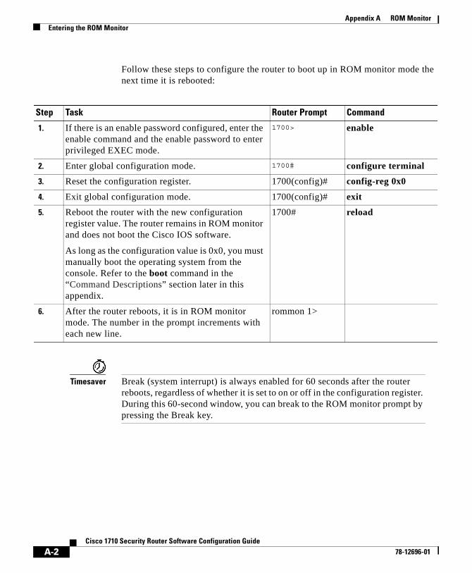
Appendix A ROM MonitorEntering the ROM Monitor
Follow these steps to configure the router to boot up in ROM monitor mode the next time it is rebooted:
Timesaver Break (system interrupt) is always enabled for 60 seconds after the router reboots, regardless of whether it is set to on or off in the configuration register. During this 60-second window, you can break to the ROM monitor prompt by pressing the Break key.
Step Task Router Prompt Command
1. If there is an enable password configured, enter the enable command and the enable password to enter privileged EXEC mode.
1700> enable
2. Enter global configuration mode. 1700# configure terminal
3. Reset the configuration register. 1700(config)# config-reg 0x0
4. Exit global configuration mode. 1700(config)# exit
5. Reboot the router with the new configuration register value. The router remains in ROM monitor and does not boot the Cisco IOS software.
As long as the configuration value is 0x0, you must manually boot the operating system from the console. Refer to the boot command in the “Command Descriptions” section later in this appendix.
1700# reload
6. After the router reboots, it is in ROM monitor mode. The number in the prompt increments with each new line.
rommon 1>
A-2Cisco 1710 Security Router Software Configuration Guide
78-12696-01

Appendix A ROM MonitorROM Monitor Commands
ROM Monitor CommandsEnter ? or help at the ROM monitor prompt to display a list of available commands and options, as follows:
rommon 1 > ?alias set and display aliases commandboot boot up an external processbreak set/show/clear the breakpointconfreg configuration register utilitycont continue executing a downloaded imagecontext display the context of a loaded imagecookie display contents of cookie PROM in hexdev list the device tabledir list files in file systemdis display instruction streamdnld serial download a program moduleframe print out a selected stack framehelp monitor builtin command helphistory monitor command historymeminfo main memory informationrepeat repeat a monitor commandreset system resetset display the monitor variablesstack produce a stack tracesync write monitor environment to NVRAMsysret print out info from last system returntftpdnld tftp image downloadunalias unset an aliasunset unset a monitor variablexmodem x/ymodem image download
Commands are case sensitive. You can halt any command by pressing the Break key on a terminal. If you are using a PC, most terminal emulation programs halt a command when you press the Ctrl and the Break keys at the same time. If you are using another type of terminal emulator or terminal emulation software, refer to the documentation for that product for information on how to send a Break command.
A-3Cisco 1710 Security Router Software Configuration Guide
78-12696-01

Appendix A ROM MonitorCommand Descriptions
Command DescriptionsThis section describes the most commonly used ROM monitor commands:
Table A-1 Most Commonly Used ROM Monitor Commands
Command Description
help or ? Displays a summary of all available ROM monitor commands.
-? Displays information about command syntax, for example:
rommon 16 > dis -?usage : dis [addr] [length]
The output for this command is slightly different for the xmodem download command:
rommon 11 > xmodem -?xmodem: illegal option -- ?usage: xmodem [-cyrx] <destination filename>-c CRC-16-y ymodem-batch protocol-r copy image to dram for launch-x do not launch on download completion
reset or i Resets and initializes the router, similar to a power up.
dev Lists boot device identifications on the router. For example:
rommon 2> devDevices in device table: id name flash: flash eprom: eprom
dir device: Lists the files on the named device (Flash, for example):
rommon 1> dir flash: File size Checksum File name 7729736 bytes (0x75f248) 0xb86d c1700-bk9no3r2sy7-mz.0412
Boot Commands For more information about the ROM monitor boot commands, see the Cisco IOS Configuration Guide and Cisco IOS Command Reference publications.
b Boots the first image in Flash memory.
A-4Cisco 1710 Security Router Software Configuration Guide
78-12696-01

Appendix A ROM MonitorDisaster Recovery with TFTP Download
Disaster Recovery with TFTP DownloadThe standard way to load new software on your router is using the copy tftp flash privileged EXEC command from the Cisco IOS software command-line interface (CLI). However, if the router is unable to boot the Cisco IOS software, you can load new software while in ROM monitor mode.
This section describes how to, while in ROM monitor mode, load a Cisco IOS software image from a remote TFTP server to the router Flash memory. Use the tftpdnld command only for disaster recovery because it erases all existing data in Flash memory before downloading a new software image to the router.
Note The 10BASE-T Ethernet Port is not active in ROM monitor mode, and thus cannot be used for TFTP Download.
TFTP Download Command VariablesThis section describes the system variables that can be set in ROM monitor mode and that are used during the TFTP download process. There are required and optional variables.
Note The commands described in this section are case-sensitive and must be entered exactly as shown in the lists.
b flash: [filename] Attempts to boot the image directly from the first partition of Flash memory. If you do not enter a filename, this command will boot this first image in Flash.
b flash:2: [filename] Attempts to boot the image directly from the second partition of Flash memory. f you do not enter a filename, this command will boot this first image in the second partition of Flash memory.
Table A-1 Most Commonly Used ROM Monitor Commands (continued)
Command Description
A-5Cisco 1710 Security Router Software Configuration Guide
78-12696-01
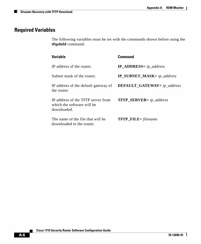
Appendix A ROM MonitorDisaster Recovery with TFTP Download
Required Variables
The following variables must be set with the commands shown before using the tftpdnld command:
Variable Command
IP address of the router. IP_ADDRESS= ip_address
Subnet mask of the router. IP_SUBNET_MASK= ip_address
IP address of the default gateway of the router.
DEFAULT_GATEWAY= ip_address
IP address of the TFTP server from which the software will be downloaded.
TFTP_SERVER= ip_address
The name of the file that will be downloaded to the router.
TFTP_FILE= filename
A-6Cisco 1710 Security Router Software Configuration Guide
78-12696-01

Appendix A ROM MonitorDisaster Recovery with TFTP Download
Optional Variables
The folowing variables can be set with the commands shown before using the tftpdnld command:
Variable Command
Configures how the router displays file download progress.
0—No progress is displayed.
1—Exclamation points (!!!) are displayed to indicate file download progress. This is the default setting.
2—Detailed progress is displayed during the file download process. For example:
Initializing interface.
Interface link state up.
ARPing for 1.4.0.1
ARP reply for 1.4.0.1 received. MAC address 00:00:0c:07:ac:01
TFTP_VERBOSE= setting
Number of times the router attempts ARP and TFTP download. The default is 7.
TFTP_RETRY_COUNT= retry_times
Amount of time, in seconds, before the download process times out. The default is 2, 400 seconds (40 minutes).
TFTP_TIMEOUT= time
Whether or not the router performs a checksum test on the downloaded image:
1—Checksum test is performed.
0—No checksum test is performed.
TFTP_CHECKSUM=setting
A-7Cisco 1710 Security Router Software Configuration Guide
78-12696-01

Appendix A ROM MonitorDisaster Recovery with TFTP Download
Using the TFTP Download CommandThe steps described in this section should be performed while in ROM monitor mode.
Step 1 Use the appropriate commands to enter all the required variables and any optional variables described earlier in this section.
Step 2 Enter the tftpdnld command as follows:
rommon 1 > tftpdnld [ -r ]
Note The -r variable is optional. Entering this variable downloads and boots the new software but does not save the software to Flash. You can then use the image that is in Flash the next time you enter the reload command in the Cisco IOS software CLI.
You will see output similar to the following:
IP_ADDRESS: 10.0.0.1 IP_SUBNET_MASK: 255.255.0.0 DEFAULT_GATEWAY: 1.3.0.1 TFTP_SERVER: 223.255.254.254 TFTP_FILE: c1700-bnr2sy-mz.070298Invoke this command for disaster recovery only.WARNING: all existing data in all partitions on flash will be lost!Do you wish to continue? y/n: [n]:
Step 3 If you are sure that you want to continue, enter y in response to the question in the output:
Do you wish to continue? y/n: [n]:y
The router will begin to download the new file.
Pressing Ctrl-C or Break stops the transfer before the Flash memory is erased.
A-8Cisco 1710 Security Router Software Configuration Guide
78-12696-01

Appendix A ROM MonitorConfiguration Register
Configuration RegisterThe virtual configuration register is in NVRAM and has the same functionality as other Cisco routers. You can view or modify the virtual configuration register from either the ROM monitor or the operating system software.
To change the virtual configuration register from the ROM monitor, enter confreg by itself for menu mode, or enter the new value of the register in hexadecimal.
confreg [hexnum]—Change the virtual configuration register to the value specified. The value is always interpreted as hexadecimal. Entering confreg without an argument displays the contents of the virtual configuration register and a prompt to alter the contents by describing the meaning of each bit.
In either case, the new virtual configuration register value is written into NVRAM, but does not take effect until you reset or power-cycle the router.
The following display shows an example of menu mode:
rommon 7> confreg Configuration Summaryenabled are:console baud: 9600boot: the ROM Monitor do you wish to change the configuration? y/n [n]: yenable “diagnostic mode”? y/n [n]: yenable “use net in IP bcast address”? y/n [n]: enable “load rom after netboot fails”? y/n [n]: enable “use all zero broadcast”? y/n [n]: enable “break/abort has effect”? y/n [n]: enable “ignore system config info”? y/n [n]: change console baud rate? y/n [n]: yenter rate: 0 = 9600, 1 = 4800, 2 = 1200, 3 = 2400 4 = 19200, 5 = 38400, 6 = 57600, 7 = 115200 [0]: 0change the boot characteristics? y/n [n]: yenter to boot: 0 = ROM Monitor 1 = the boot helper image 2-15 = boot system [0]: 0 Configuration Summaryenabled are:diagnostic modeconsole baud: 9600
A-9Cisco 1710 Security Router Software Configuration Guide
78-12696-01

Appendix A ROM MonitorConsole Download
boot: the ROM Monitor do you wish to change the configuration? y/n [n]: You must reset or power cycle for new config to take effect
Console DownloadYou can use console download, a ROM monitor function, to download over the router console port either a software image or a configuration file. After download, the file is either saved to the mini-Flash module or to main memory for execution (image files only).
Use console download when you do not have access to a TFTP server.
Note If you want to download a software image or a configuration file to the router over the console port, you must use the ROM monitor command.
Note If you are using a PC to download a Cisco IOS image over the router console port at 115,200 bps, ensure that the PC serial port is using a 16550 universal asynchronous receiver/transmitter (UART). If the PC serial port is not using a 16550 UART, we recommend using a speed of 38,400 or lower when downloading a Cisco IOS image over the console port.
A-10Cisco 1710 Security Router Software Configuration Guide
78-12696-01

Appendix A ROM MonitorConsole Download
Command DescriptionFollowing are the syntax and argument descriptions for the xmodem console download command.
The syntax is as follows:
xmodem [-cyrx] destination_file_name
The argument descriptions are as follows:
Argument Description
c Optional. Performs the download using CRC-16 error checking to validate packets. Default is 8-bit CRC.
y Optional. Sets the router to perform the download using ymodem protocol. Default is xmodem protocol. The protocols differ as follows:
• xmodem supports a 128-block transfer size. ymodem supports a 1024-block transfer size.
• ymodem uses 16-bit cyclic redundancy check (CRC)-16 error checking to validate each packet. Depending on the device that the software is being downloaded from, this function might not be supported by xmodem.
r Optional. Image is loaded into DRAM for execution. Default is to load the image into Flash memory.
x Optional. Image is loaded into DRAM without being executed.
destination_file_name The name of the system image file or the system configuration file. In order for the router to recognize it, the name of the configuration file must be router_confg.
A-11Cisco 1710 Security Router Software Configuration Guide
78-12696-01

Appendix A ROM MonitorDebug Commands
Error ReportingBecause the ROM monitor console download uses the console to perform the data transfer, error messages are displayed on the console only when the data transfer is terminated.
If an error does occur during a data transfer, the transfer is terminated, and an error message is displayed. If you have changed the baud rate from the default rate, the error message is followed by a message telling you to restore the terminal to the baud rate specified in the configuration register.
Debug CommandsMost ROM monitor debugging commands are functional only when Cisco IOS software has crashed or is halted. If you enter a debugging command and Cisco IOS crash information is not available, you see the following error message:
"xxx: kernel context state is invalid, can not proceed."
The following are ROM monitor debugging commands:
• stack or k—Produce a stack trace. For example:
rommon 6> stackStack trace:PC = 0x801111b0Frame 00: FP = 0x80005ea8 PC = 0x801111b0Frame 01: FP = 0x80005eb4 PC = 0x80113694Frame 02: FP = 0x80005f74 PC = 0x8010eb44Frame 03: FP = 0x80005f9c PC = 0x80008118Frame 04: FP = 0x80005fac PC = 0x80008064Frame 05: FP = 0x80005fc4 PC = 0xfff03d70
• context—Display processor context. For example:
rommon 7> contextCPU context of the most recent exception:PC = 0x801111b0 MSR = 0x00009032 CR = 0x53000035 LR = 0x80113694CTR = 0x801065e4 XER = 0xa0006d36 DAR = 0xffffffff DSISR = 0xffffffffDEC = 0xffffffff TBU = 0xffffffff TBL = 0xffffffff IMMR = 0xffffffffR0 = 0x00000000 R1 = 0x80005ea8 R2 = 0xffffffff R3 = 0x00000000
A-12Cisco 1710 Security Router Software Configuration Guide
78-12696-01

Appendix A ROM MonitorDebug Commands
R4 = 0x8fab0d76 R5 = 0x80657d00 R6 = 0x80570000 R7 = 0x80570000R8 = 0x00000000 R9 = 0x80570000 R10 = 0x0000954c R11 = 0x00000000R12 = 0x00000080 R13 = 0xffffffff R14 = 0xffffffff R15 = 0xffffffffR16 = 0xffffffff R17 = 0xffffffff R18 = 0xffffffff R19 = 0xffffffffR20 = 0xffffffff R21 = 0xffffffff R22 = 0xffffffff R23 = 0xffffffffR24 = 0xffffffff R25 = 0xffffffff R26 = 0xffffffff R27 = 0xffffffffR28 = 0xffffffff R29 = 0xffffffff R30 = 0xffffffff R31 = 0xffffffff
• frame—Display an individual stack frame.
• sysret—Display return information from the last booted system image. This information includes the reason for terminating the image, a stack dump of up to eight frames, and, if an exception is involved, the address where the exception occurred. For example:
rommon 8> sysretSystem Return Info:count: 19, reason: user breakpc:0x801111b0, error address: 0x801111b0Stack Trace:FP: 0x80005ea8, PC: 0x801111b0FP: 0x80005eb4, PC: 0x80113694FP: 0x80005f74, PC: 0x8010eb44FP: 0x80005f9c, PC: 0x80008118FP: 0x80005fac, PC: 0x80008064FP: 0x80005fc4, PC: 0xfff03d70FP: 0x80005ffc, PC: 0x00000000FP: 0x00000000, PC: 0x00000000
• meminfo—Display size in bytes, starting address, available range of main memory, the starting point and size of packet memory, and size of nonvolatile random-access memory (NVRAM). For example:
rommon 3> meminfo
Main memory size: 64 MB.Available main memory starts at 0x10000, size 65472KBIO (packet) memory size: 25 percent of main memory.NVRAM size: 32KB
A-13Cisco 1710 Security Router Software Configuration Guide
78-12696-01

Appendix A ROM MonitorDebug Commands
A-14Cisco 1710 Security Router Software Configuration Guide
78-12696-01

Cisco 1710 R78-12696-01
I N D E X
A
access-group command 2-13
access-list commands 2-13
access lists
configuration 2-13
examples 2-14
accounting
per VLAN 3-4
Quality of Service (QoS) 3-4
appletalk cable-range command 4-3
appletalk routing eigrp command 4-2
appletalk zone command 4-3
B
boot in ROM monitor mode A-2
bridging domain 3-2
broadcast
control 3-3
domain 3-2
C
caution, definition xiii
clear vlan statistics command 4-8
command modes
Cisco IOS 1-2
summary (table) 1-4
commands
access-group 2-13
access-list 2-13
appletalk cable-range 4-3
appletalk routing eigrp 4-2
appletalk zone 4-3
clear vlan statistics 4-8
context A-12
crypto 2-3
debug vlan packets 4-9
dev (device) A-4
dir A-4
enable 1-7
enable secret 1-7
encapsulation dot1q 4-10
frame A-13
inspect name 2-15
interface 2-7, 4-3, 4-4, 4-6
ipx network 4-6
ipx routing 4-5
meminfo A-13
IN-1outer Software Configuration Guide

Index
reset A-4
show vlans 4-9, 4-11
stack A-12
sysret A-13
tftpdnld A-5
commands, abbreviating 1-9
common error messages 1-9
configuration register A-9
configuring the router
basic configuration procedures 2-1
preliminaries 2-2
saving your configuration 1-10
console download A-10
context command A-12
conventions xii to xiii
crypto commands 2-3
crypto engine accelerator command 2-5
D
debug commands
additional documentation 1-11
caution 1-11
ROM monitor A-12
turning off 1-11
using in a Telnet session 1-11
when to use 1-11
debug vlan packets command 4-9
dev (device) command A-4
IN-2Cisco 1710 Router Software Configuration Guide
DHCP
configuration 2-8
example 2-8
manual binding example 2-9
dialer interface configuration 2-6
dir command A-4
disabling hardware encryption 2-4
domain
bridging 3-2
broadcast 3-2
Dynamic Host Configuration Protocol
See DHCP
E
enable
password 1-7
secret 1-7
encapsulation dot1q command 4-10
error messages, description of (table) 1-9
ethernet interface configuration 2-7
EXEC mode 1-7
F
firewall configuration 2-12
firewalls
and access lists 2-13 to 2-15
and inspection rules 2-15
78-12696-01

Index
frame command A-13
frame tagging, VLANs 3-4
H
hardware encryption
disabling 2-4
re-enabling 2-5
help, how to get it 1-6
hybrid switching environments 3-6
I
inspection rules 2-15
inspect name command 2-15
interface command 2-7, 4-3, 4-4, 4-6
inter-VLAN communication 3-4
IPSec configuration 2-3
ipx network command 4-6
ipx routing command 4-5
L
LAN
segmentation 3-2, 3-3
Layer 2, encapsulating interfaces 3-6
Ci78-12696-01
M
meminfo command A-13
N
NAT
configuration 2-10
configuration example 2-11
network
design concerns 3-5
management 3-4
services
accounting 3-4
quality of service (QoS) 3-4
security filtering 3-4
topology 3-5
Network Address Translation
See NAT
no crypto engine accelerator command 2-4
note, definition xiii
P
packets, VLAN 4-9
password
enable 1-7
enable secret 1-7
performance 3-4
IN-3sco 1710 Router Software Configuration Guide

Index
prompts
for command modes (table) 1-4
R
reset command A-4
resources, sharing between VLANs 3-6
ROM monitor
commands A-3 to A-5
console download A-10
debug commands A-12
diagnostics A-12 to A-13
entering A-1
ROM monitor commands
context A-12
dev (device) A-4
dir A-4
frame A-13
meminfo A-13
stack A-12
sysret A-13
tftpdnld A-5
router configuration register A-9
routers, in switched VLANs 3-6
S
sample configuration 2-15 to 2-19
saving your configuration 1-10
IN-4Cisco 1710 Router Software Configuration Guide
security
filtering 3-4
VLANs 3-3
Security, IP
See IPSec
segmentation 3-2, 3-3
show vlans command 4-9, 4-11
software
conventions xii to xiii
terminal emulation 1-2
stack command A-12
sysret command A-13
T
terminal emulation software, settings 1-2
timesaver, definition xiii
traffic
broadcast 3-3
controlling patterns 3-5
multicast 3-3
translation, in VLANs 3-6
V
virtual LANs
See VLANs
virtual private dialup network
See VPDN
78-12696-01
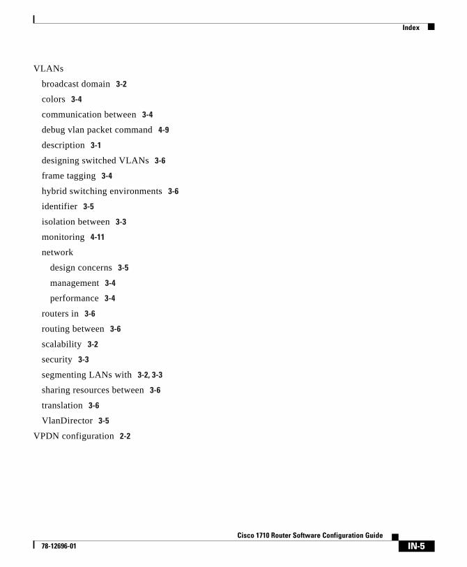
Index
VLANs
broadcast domain 3-2
colors 3-4
communication between 3-4
debug vlan packet command 4-9
description 3-1
designing switched VLANs 3-6
frame tagging 3-4
hybrid switching environments 3-6
identifier 3-5
isolation between 3-3
monitoring 4-11
network
design concerns 3-5
management 3-4
performance 3-4
routers in 3-6
routing between 3-6
scalability 3-2
security 3-3
segmenting LANs with 3-2, 3-3
sharing resources between 3-6
translation 3-6
VlanDirector 3-5
VPDN configuration 2-2
Ci78-12696-01
IN-5sco 1710 Router Software Configuration Guide

Index
IN-6Cisco 1710 Router Software Configuration Guide
78-12696-01