CIRCULAR POLARIZED TEXTILE ANTENNA UMAR MUSA A project...
22
CIRCULAR POLARIZED TEXTILE ANTENNA UMAR MUSA A project report submitted in partial fulfilment of the requirements for the award of the degree of Master of Engineering (Electronics and Telecommunications) Faculty of Electrical Engineering Universiti Teknologi Malaysia December 2015
Transcript of CIRCULAR POLARIZED TEXTILE ANTENNA UMAR MUSA A project...
CIRCULAR POLARIZED TEXTILE ANTENNA
UMAR MUSA
A project report submitted in partial fulfilment of the
requirements for the award of the degree of
Master of Engineering (Electronics and Telecommunications)
Faculty of Electrical Engineering
Universiti Teknologi Malaysia
December 2015

iii
DEDICATION
To my honoured and esteemed family, friends and
all those who have contributed in this project
for their continuous motivation, support and encouragement.

iv
ACKNOWLEDGEMENT
First and foremost, thanks God, for blessing me the strength to complete this
study. I wish to express my gratitude to several people that helped me during the
course of my master’s programme at Universiti Teknologi Malaysia.
I would like to acknowledge my supervisor Professor. Dr. Mohammad Kamal
Abdul Rahim who has given me support and guidance throughout the period of this
project. His patience and perseverance towards the outcome of this study is of the
highest standard. Without him this project report will not become a reality.
I am very grateful to my parents, for their endless prayers, love and
encouragement, not only during this master’s program, but also during all my life.
My late father may his soul rest in perfect peace and grant him jannatul firdaus. My
mum May god protect and guide you. I wish to express my love and gratitude to
other members of my family, especially my sisters and brothers, for their supports
and endless love, through the duration of my studies.
Thanks all of you
Umar Musa
.
v
ABSTRACT
Recently, wearable electronic applications have arising in the commercial
market. There has been growing use of textile antennas for wearable electronic and
body centric applications such as healthcare, GPS and fire fighter personal
communications. The use of circularly polarized antennas presents an attractive
solution to achieve this polarization match which allows for more flexibility in the
angle between transmitting and receiving antennas The new generation of textile has
the capability to conduct electricity and at the same time as wearable. Microstrip
patch antennas represent one family of compact antennas that offer a conformal
nature and the capability of ready integration with communication system’s printed
circuitry. In this project, a circular polarized (CP) textile antenna is designed and
simulated at 2.4GHz. To achieve circular polarization an inverted z slot asymmetrical
structure is introduced at the center of radiating element, once incorporated onto the
square patch two orthogonal components of electric field are excited with a 900
time
phase difference. Both the patch and the inverted z slot were adjusted such that the
wearable antenna generates the circular polarized wave at the resonance frequency.
The proposed antenna has a dimension of 50mm x 50mm x 0.035mm, made by the
use of fleece textile material as a substrate with a thickness 1mm, dielectric constant
1.3 and loss tangent 0.024. The antenna is fed via a subminiature version A (SMA)
connector. The simulated and measured result shows that the antenna offers
approximately 6.7% bandwidth (2.42GHz-2.59GHz) return loss, S11 is -32.16dB with
impedance bandwidth of 167 MHz and The flexible antenna has axial ratio
bandwidth of 80 MHz i.e 3.25% covering the frequency range of (2.42GHz -
2.5GHz). The antenna has a good performance in term of axial ratio.
vi
ABSTRAK
Dewasa ini, aplikasi elektronik yang boleh dipakai telah meningkat di dalam
pasaran komersial. Telah terdapat peningkatan di dalam penggunaan antenna tekstil
untuk aplikasi elektronik boleh dipakai dan berteraskan badan seperti kesihatan, GPS
dan alat komunikasi untuk anggota keselamatan. Kegunaan antena pengutuban
bulatan memberikan penyelesaian yang baik untuk mendapatkan padanan
pengutuban kerana ianya dapat memberikan sudut yang lebih fleksibel diantara
antena pemancar dan penerima. Ciri tekstil yang terkini berupaya untuk mengalirkan
arus elektrik disamping ciri asasnya untuk dipakai. Antena tampal jalur mikro adalah
satu daripada kumpulan antenna kompak yang menawarkan sifat konformal dan
kebolehupayaan untuk diintegrasikan dengan litar sistem komunikasi. Di dalam
projek ini, antena yang boleh dipakai dengan pengutuban bulatan telah direkabentuk
dan disimulasikan pada frekuensi 2.4 GHz. Untuk menghasilkan pengutuban bulatan
ini, struktur slot tidak simetri berbentuk z terbalik telah diperkenalkan di posisi
tengah elemen pemancar iaitu antena tampal berbentul segiempat. Ini menghasilkan
dua medan elektrik komponen bersatah renjang yang berbeza fasa sebanyak 90
darjah. Antena tampal dan slot z terbalik disesuaikan supaya antena boleh dipakai ini
menghasilkan gelombang pengutuban bulatan di frekuensi memancar. Antena yang
dicadangkan ini berdimensi 50 mm x 50 mm x 0.035 mm, diperbuat menggunakan
bahan tekstil fleece sebagai subtratum dengan ketebalan 1 mm, pemalar dielektrik
1.3 dan kehilangan tangen 0.024. Antena ini telah disuapkan menggunakan
penyambung SMA. Keputusan simulasi dan pengukuran menunjukkan yang antena
mempunyai lebar jalur kehilangan balikan (S11) iaitu 167 MHz (2.42 GHz – 2.59
GHz, 6.7 %), dengan nilai terendah S11 ialah -32.16 dB. Antenna bercirikan
fleksibel ini mempunyai lebar jalur nisbah paksi sebanyak 80 MHz atau 3.25%,
merangkumi julat frekuensi antara 2.42 GHz hingga 2.5 GHz. Antenna ini
berprestasi baik terutama untuk keputusan nisbah paksi.

vii
TABLE OF CONTENTS
CHAPTER TITLE PAGE
DECLARATION ii
DEDICATION iii
ACKNOWLEDGEMENT iv
ABSTRACT v
ABSTRAK vi
TABLE OF CONTENTS vii
LIST OF TABLES x
LIST OF FIGURES xi
LIST OF ABBREVIATIONS xiii
LIST OF SYMBOLS xiv
1 INTRODUCTION 1
1.1 Introduction 1
1.2 Project Background 3
1.3 Problem Statement 4
1.4 Objectives of the work 5
1.5 Scope of Work 5
1.6 Organization of the Project 5
1.7 Summary 6
2 LITERATURE REVIEW 7
2.1 Introduction 7
2.2 Circular Polarized Antenna 7
2.2.1 Techniques for Circular Polarization 8
2.2.2 Microstrip Feeding for Circularly Polarized
Antenna 9

viii
2.2.2.1 Dual Feed Circular Polarized
Microstrip Antenna 9
2.2.2.2 Single Feed Circular Polarized
Microstrip Antenna 10
2.3 Textile Material Used as a Substrate 12
2.4 Design of Wide Band Circularly Polarized Textile
Antenna for ISM Bands at 2.4 and 5.8GHz. 13
2.4.1 Circularly Polarized Square Patch Antenna
With Trimmed Corners Using Textile
Material. 14
2.4.2 Design Investigation of a Dual-Band
Circularly-Polarized Wearable Antenna. 15
2.4.3 A circularly polarized slot antenna for high
gain applications. 17
2.4.4 Compact Circularly Polarized Textile
Antenna. 18
2.4.5 Circular Polarization Reconfigurable
Wideband E-Shaped Patch Antenna for
Wireless Application. 19
2.4.6 A Wearable Wideband Circularly Polarized
Textile Antenna for Effective Power
Transmissiion on a Wirelessly-Powered
Sensor Platform. 20
2.4.7 Planar Wideband Circularly Polarized
Antenna Design With Rectangular Ring
Dielectric Resonator and Printed Loops 21
2.5 Summary 29
3 METHODOLOGY 30
3.1 Introduction 30
3.2 Flow of Project 30
3.3 Circular Polarized Textile Antenna Design 32
3.3.1 Design Specifications and Parameters 33
3.3.2 Material Specifications and Parameters 33

ix
3.4 Circular Polarized Textile Antenna Calculation
Process 34
3.5 Simulation Process 36
3.5.1 Antenna Geometry 37
3.5.2 Antenna Feeding 38
3.6 Fabrication Process 40
3.7 Measurement Process 41
3.8 Summary 42
4 RESULTS AND DISCUSSION 43
4.1 Introduction 43
4.2 Simulation Results 43
4.2.1 Parametric Study 44
4.2.2 Optimum simulation results 48
4.3 Fabricated antenna and Measurement results 52
4.3.1 Fabricated Circular Polarized Textile
Antenna 52
4.3.2 Measured results 53
4.4 Comparison between the 3 types of polarization 58
4.5 Summary 58
5 CONCLUSION AND FUTURE WORK 60
5.1 Conclusion 60
5.2 Recommendation for Future Work 61
REFERENCES 63

x
LIST OF TABLES
TABLE NO. TITLE PAGE
2.1 Summary of Previous Work 22
3.1 Design Specifications and Parameters 33
3.2 Material Specifications and Parameters 34
3.3 Optimized Parameters of the proposed antenna 38
3.4 Simulation Coaxial Port Parameters 40
4.1 Comparison between 3 types of polarization. 58
xi
LIST OF FIGURES
FIGURE NO. TITLE PAGE
1.1 Schematic of a simple patch microstrip antenna 2
2.1 Techniques to give Circular Polarized antenna 8
2.2 Dual fed circular polarized patches examples 10
2.3 Single fed circular polarized patches examples 11
2.4 Coaxial feeding 11
2.5 The Geometry of the Wide Band Circularly Polarized
Textile Antenna for ISM Bands at 2.4 and 5.8 GHz. 14
2.6 The Geometry of the Circularly Polarized Square Patch
Antenna. 15
2.7 The Geometry of the Design Investigation of a Dual-Band
Circularly-Polarized Wearable Antenna. 16
2.8 The Geometry of the circularly polarized slot antenna for
high gain application. 17
2.9 The Geometry of the Compact Circularly Polarized Textile
Antenna 1 and Antenna 2. 18
2.10 The Geometry of the Circular Polarization Reconfigurable
Wideband Patch Antenna. 19
2.11 A Wearable Wideband Circularly Polarized Textile
Antenna for Effective Power Transmission. 20
2.12 The Geometry of the Planar Wideband Circularly Polarized
Antenna Design with Dielectric Resonator and Parasitic
Printed Loops. 21
3.1 The flow chart of the entire project 32
3.2 Environment of CST Software 36
3.3 Optimized Geometry of the Proposed Antenna 37
xii
3.4 Simulation Coaxial Port 39
3.5 a) R&S ZVL network analyzer, b) Anechoic Chamber 41
4.1 Effect of length and width of the patch on return loss. 44
4.2 Effect of horizontal slot on return loss and axial ratio. 45
4.3 Effect of vertical slot on axial ratio. 46
4.4 Effect of vertical slot on return loss. 46
4.5 Effect of changing the position of coaxial feeding on return
loss. 47
4.6 Effect of changing the position of coaxial feeding on axial
ratio. 47
4.7 Simulated Return loss of the proposed antenna. 48
4.8 Simulated Axial ratio of the proposed antenna. 49
4.9 Simulated radiation pattern for E-plane of the proposed
antenna. 50
4.10 Simulated radiation pattern for H-plane of the proposed
antenna. 50
4.11 Simulated 3D radiation pattern of the proposed antenna 51
4.12 Current distribution of the proposed antenna 51
4.13 Fabricated proposed circular polarized textile antenna 53
4.14 Measured return loss of the proposed antenna 54
4.15 Measured axial ratio of the proposed antenna 54
4.16 Simulated and Measured return loss of the proposed antenna 55
4.17 Simulated and Measured axial ratio of the proposed antenna 56
4.18 Simulated and Measured return loss of the proposed antenna
unbent and bent. 57
xiii
LIST OF ABBREVIATIONS
WIFI - Wireless Fidelity
CP - Circular Polarization
WLAN - Wireless Local Area Network
GPS - Global Positioning System
LHCP - Left Hand Circular Polarization
RHCP - Right Hand Circular Polarization
dB - Decibel
CST - Computer Simulation Software
BW% - Bandwidth Percentage
BW - Bandwidth
GHz - Giga Hertz
mm - Millimeter
IEEE - Institute of Electrical and Electronic Engineers
RL - Return Loss
AR - Axial Ratio
BCWC - Body-Centric Wireless Communications
SMA - Subminiature Version A
RF - Radio Frequency

xiv
LIST OF SYMBOLS
LP - Patch length
WP - Patch width
WS - Substrate width
LS - Substrate length
LSlot - Length of slot
WSlot - Width of slot
Fo - Resonant frequency
λo - Free space wave length
λeff - Effective wavelength
ℰr - Substrate dielectric constant
ℰeff - Effective substrate dielectric constant
C - Speed of light
CHAPTER 1
INTRODUCTION
1.1 Introduction
Wearable antenna investigation now a days that focus on body worn
application is rapidly growing, which provide a tremendous range of application such
as fire fighter, health care and body centric communication. microstrip antennas is
one of the most commonly used antennas in applications which required Circular
polarization, regardless of receiver orientation the antenna would be able to received
a component of signal, Circular polarization (CP) microstrip antennas are getting
more attention in modern mobile wireless communications, in mobile and portable
wireless application where wireless devices frequently change their location and
orientation it is nearly impossible to constantly match the spatial orientation of the
devices. Circularly polarized antennas could be matched in wide range of
orientations because the radiated waves oscillate in a circle that is perpendicular to
the direction of propagation [1-3]. To achieve this polarization matching the
transmitter and the receiver should have the same axial ratio, spatial orientation and
the same sense of polarization. This project is concerned with the design of a
circularly polarized microstrip antenna that would operate in the 2.4 GHz range. This
range is commonly used by wireless local area devices and wireless personal area
devices such as the 802.11 WIFI and the 802.15.4 Zigbee wireless systems. [13]
Designing a circularly polarized microstrip antenna is challenging; it requires
combination of design steps. The first step involves designing an antenna to operate
at a given frequency. In the second step circular polarization is achieved by either
2
introducing a perturbation segment to a basic single fed microstrip antenna, or by
feeding the antenna with dual feeds equal in magnitude but having 90° physical
phase shift. The shape and the dimensions of the perturbation have to be optimized to
ensure that the antenna achieves an axial ratio that is below 3 dB at the desired
design frequency. However for wider angles it is difficult to maintain the
orthogonality of these components. For microstrip patch antennas, which are very
convenient due to easy manufacturability, the ground plane attenuates the electric
component parallel to it, degrading the axial ratio. So far proposed omnidirectional
CP antennas usually either use multiple radiators or complex polarisers. Neither of
these solutions are convenient for applications on small portable devices. Compact
and easy to manufacture omnidirectional CP antennas could have many applications.
[11-14]
The main advantage of CP is that regardless of receiver orientation, it will
receive a component of signal. However, CP can be archived using single element or
arrays of microstrip antenna. [7]
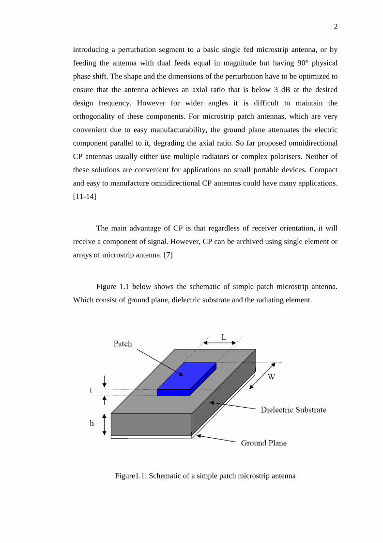
Figure 1.1 below shows the schematic of simple patch microstrip antenna.
Which consist of ground plane, dielectric substrate and the radiating element.
Figure1.1: Schematic of a simple patch microstrip antenna
3
1.2 Project Background
The investigation on wearable devices which focus on body-worn
communication is rapidly growing, the interest in implementing textile technology as
a wearable antenna for body worn communication has gained huge attention since
the fabric material does not force the wearer to abandon the comfort zone The
wearable electronic devices are such devices worn by a person as un obstructively as
clothing to provide intelligent assistance. The key considerations for wearable
electronics are to be robust, flexible, small size, consume a small amount of power,
and comfortable to wear.[8]
Modern technology requires the antenna in more compact and also applicable
for body worn application in which Textile material forms interesting substrate
because fabric antenna can be easily integrated into clothes with low profile and ease
of fabrication. The applications of wireless communication such as Global
positioning systems (GPS), WLAN, satellite communication require more bandwidth
due to integration of various services in single receiver [10].
In order to achieve circular polarization using only a single feed, two modes
should be exited with equal amplitude and 90° out of phase. Since basic microstrip
antenna shapes produce linear polarization there must be some deviation in the patch
design to produce circular polarization. Perturbation segments are used to split the
field into two orthogonal modes with equal magnitude and 90° phase shift. Therefore
the circular polarization requirements are met. To generate circular polarization, two
orthogonal components of electric field are needed. These components need to be
equal in amplitude, but shifted in phase by 90°. CP antennas are demanding to
design, however offer multiple benefits. [11-13]
This project achieves circular polarization by introducing a perturbation in
the form of inverted z slot to the patch antenna. Truncated edges have been used to
achieve circular polarization in square, elliptical and circular patch in [4-6]. The
work in [6] used a single feeding and did not provide details about the parametric
4
optimization of this antenna. Dual feeding is not suitable for microstrip patch since it
requires power divider, complexity and not easy to matched. [10]
Coaxial feeding techniques are commonly used because they are simple, easy
to manufacture, low in cost, can be located anywhere in the patch and compact in
structure. Single fed circularly polarized microstrip antennas are considered to be one
of the simplest antennas that can produce circular polarization [7]. In order to
achieve circular polarization using only a single feed, two modes should be exited
with equal amplitude and 90° out of phase. Since basic microstrip antenna shapes
produce linear polarization there must be some deviation in the patch design to
produce circular polarization. Perturbation segments are used to split the field into
two orthogonal modes with equal magnitude and 90° phase shift. Therefore the
circular polarization requirements are met. [13]
1.3 Problem Statement
Recently, wearable electronic applications have arising in the commercial
market. There has been growing use of textile antennas for wearable electronic and
body centric applications such as healthcare, GPS and fire fighter personal
communications.
Therefore, by using fabric as the substrate and the limitation of the
transmitter-to-receiver orientation can be effectively solved when antennas with
circular polarization (CP) are utilized every person who is using wired technology
device can easily move around while doing their job. The person can wear the
wearable device onto their cloth. So, the problems of limited movements are
considered solved.

5
1.4 Objectives of the work
The objectives of this research are as follows:
To design, simulate a circular polarized antenna at 2.4GHz using microstrip
Technique.
To fabricate the antenna on fleece textile substrate.
To compare the simulated and measured result i.e. axial ratio, return loss and
Radiation pattern are in good agreement.
1.5 Scope of Work
The project is restricted within the below limitations:
i. Design and simulate a circular polarized textile antenna.
ii. Utilizing fleece material as substrate to design the antenna.
iii. Analyze the simulated result using CST Microwave Studio in terms of
antenna properties such as return loss, radiation pattern and axial ratio.
iv. Fabrication and measurement of the antenna and comparison between
simulation and measurement.
1.6 Organization of the Project
This thesis is divided into five chapters. Each chapter will discuss on the
different issues related to this project. Following are the outlines of the project for
each chapter.
Chapter 1: covered the introduction and overview of the project background,
problem statement, objective, and scope of work of this project. All of the data
should be stated clearly before designing the antenna.

6
Chapter 2: A literature review on previous works focusing circular polarized
textile antenna to get clear view of the title project.
Chapter 3: explained the flowchart and the methodology that will be done to
finish the project successfully. The design specification which includes the fleece
fabric as a substrate is presented in this chapter.
Chapter 4: presents the results and discussion of the project. Simulated and
measured results for return loss, radiation patterns and axial ratio are analyzed.
Chapter 5: gives the summarized works and conclusion for the overall of the
project. Besides, future works and recommendations to improve the performance of
the designed antenna are also stated.
1.7 Summary
In this chapter, the overview of circular polarized textile antenna, problem
statement, the objective of this project, and scope of project are all stated clearly.
REFERENCES
[1] N. Sharma and A. Goen, "Circularly Polarized Square Patch Antenna with
Trimmed Corners Using Textile Material. “International Journal of Advanced
Research in Electrical, Electronics and Instrumentation Engineering. Vol 4,
Issue 1 January 2015.
[2] R. R. Krishna, R. Kumar, and N. Kushwaha, "A circularly polarized slot
antenna for high gain applications," AEU-International Journal of Electronics
and Communications, vol. 68, pp. 1119-1128, 2014.
[3] M. F. Ismail, M. K. A. Rahim, E. I. S. Saadon, and M. S. Mohd, "Compact
circularly polarized textile antenna," in Wireless Technology and
Applications (ISWTA), 2014 IEEE Symposium on, 2014, pp. 134-136.
[4] A. Khidre, K.-F. Lee, F. Yang, and A. Z. Elsherbeni, "Circular polarization
reconfigurable wideband E-shaped patch antenna for wireless applications,
"Antennas and Propagation, IEEE Transactions on, vol. 61, pp. 960-964,
2013.
[5] K. W. Lui, O. H. Murphy, and C. Toumazou, "A Wearable Wideband
Circularly Polarized Textile Antenna for Effective Power Transmission on a
Wirelessly-Powered Sensor Platform," Antennas and Propagation, IEEE
Transactions on, vol. 61, pp. 3873-3876, 2013.
[6] M. Khalily, M. K. Rahim, and A. A. Kishk, "Planar wideband circularly
polarized antenna design with rectangular ring dielectric resonator and parasitic
printed loops," Antennas and Wireless Propagation Letters, IEEE, vol. 11, pp.
905-908, 2012.
[7] S. Murugan and V. Rajamani, "Design of Wideband Circularly Polarized
Capacitive fed Microstrip Antenna," Procedia Engineering, vol. 30, pp. 372-
379, 2012.
[8] O. Malyuskin and V. Fusco, "Wideband circular polarized antenna with high
polarization purity over a wide angular range," in Antennas and Propagation
(EUCAP), 2012 6th
European Conference on, 2012, pp. 2764-2765.
[9] P. Mousavi, B. Miners, and O. Basir, "Wideband L-shaped circular polarized
monopole slot antenna," Antennas and Wireless Propagation Letters, IEEE,
vol. 9, pp. 822-825, 2010.
[10] S. Kim and W. Yang, "Single feed wideband circular polarized patch antenna,
“Electronics Letters, vol. 43, pp. 703-704, 2007.
64
[11] D. M. Pozar, Microwave and RF Design of Wireless Systems, John Wiley &
Son, Inc, 2001.
[12] David M.Pozar “Microstrip Antennas” IEEE proceedings, vol. 80, No.1, 1992,
pp. 79-91.
[13] R. Garg, P. Bhartia, I. Bahl , A. Ittipiboon, Microstrip Antenna Design
Handbook, Arteck House, 2001.
[14] C. A. Balanis, Antenna Theory Analysis and Design 3rd edition, John Wiley
& Sons, Inc., 2005.
[15] Y. T. Lo, S. W. Lee, Antenna Handbook, Van Nostrand Reinhold, 1993.
[16] P. Serka, D. Bhatnagar, V.K. Saxena, J.S.Saini, “Single Feed Circularly
Polarized Edge Truncated Elliptical Microstrip Antenna,” in proceedings of the
International Conference on Emerging Trends in Electronic and Photonic
Devices and Systems ELECTRO, 2009, pp. 353-356.
[17] M. Rahmani, A. Tavakoli, H. R. Amindavar, A. M. Reza, P. Dehkhoda,
“Chalipa, a novel wideband circularly polarized microstrip fractal antenna” in
Proceedings of the 3rd European Conference on Antennas and Propagation,
EuCAP, 2009, pp. 2389 – 2392.
[18] Yufeng Wang, Jianjie Feng, Jingbo Cui, Xiaolong Yang, “A Dual-Band
Circularly Polarized Stacked Microstrip Antenna with Single-Fed for GPS
Applications,” in proceedings of the 8th International Symposium on Antennas
Propagation and EM Theory, ISAPE, 2008, pp. 108 – 110.
[19] Wen-Shyang Chen, Chun-Kun Wu, Kin-Lu Wong, “Novel Compact Circularly
Polarized Square Microstrip Antenna,” IEEE Transactions on Antennas and
Propagation, Vol.49, Issue. 3, 2001, pp. 340 – 342.
[20] Nasimuddin, Xianming Qing, Zhi Ning Chen, “Microstrip Antenna with S-
Shaped Slot for Dual-Band Circularly Polarized Operation” in
proceedings of the European Microwave Conference, EuMC, 2009, pp. 381-
384.
[21] H. Iwasaki; “A Circularly Polarized Small-Size Microstrip Antenna with a
Cross Slot”, IEEE Transactions on Antennas and Propagation, vol. 44, issue.
10, 1996, pp. 1399-1401.
[22] Nasimuddin, Y. Yong, Z.N. Chen, A. Alphones, “Circularly Polarized F-
Shaped Slot Microstrip Antenna with Wide Beamwidth,” in proceedings of
the European Microwave Conference, EuMC , 2009 , pp. 1531–1534.
65
[23] A. Y. Simba, M. Yamamoto, T. Nojima, K. Itoh, “Circularly Polarised
Proximity-Fed Microstrip Antenna with Polarisation Switching Ability,” IET
Microwaves Antennas & Propagation, Vol.1, Issue. 3, 2007, pp. 658 – 665.
[24] K. Tamakuma, H. Iwasaki, “A Small Size Circularly Polarized Annular
Microstrip Antenna” in proceedings of the International Symposium IEEE
Antennas and Propagation Society, vol. 2, 2003, pp. 716 – 719.
[25] Y. Suzuki, N. Miyano, T. Chiba, “Circularly Polarised Radiation from Singly
Fed Equilateral-Triangular Microstrip Antenna,” IEE Proceedings on
Microwaves, Antennas and Propagation, vol. 134 , Issue. 2.
[26] Tso-Wei Li, Cheng-Liang Lai; Jwo-Shiun Sun, "Study of Dual-Band
Circularly Polarized Microstrip Antenna," proceedings of the European
Conference on Wireless Technology, 2005, pp. 79 – 80.
[27] J.-S. Row, C.-Y. Ai “Compact Design of Single-Feed Circularly Polarised
Microstrip Antenna” IEEE Electronics Letters, vol.40, issue: 18, 2004, pp.
1093-1094.