Circular No. 48 1955 - Illinois State Water Survey · circular standing-wave patterns in the range...
19
Transcript of Circular No. 48 1955 - Illinois State Water Survey · circular standing-wave patterns in the range...
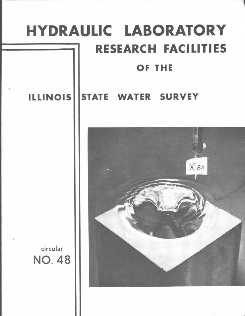

The cover illustration is one of a series of stroboscopic photographs taken during tests on a model of a drop-inlet spillway. The photograph shows circular standing-wave patterns in the range between weir and orifice flow. This work is being continued under the drop-inlet spillway project.
ACKNOWLEDGMENTS
This brochure was prepared by G. H. Nelson, Assistant Engineer, with contributions by H. £. Hudson, Jr., Head. Engineering Subdivision, and Max Suter. Head, Engineering Research Subdivision. The drawings for the section on the Urbana Laboratory were prepared by Janet Abu-Lughod, Engineering Assistant.

Circular No. 48 1955
STATE OF ILLINOIS
WILLIAM G. STRATTON, Governor
Hydraulic Laboratory Research Facilities of the
State Water Survey Division
A. M. BUSWELL, Chief
DEPARTMENT OF REGISTRATION AND EDUCATION
VERA M. BINKS, Director
(Printed by the authority of the State of Illinois)
CONTENTS
Page Functions of State Water Survey 1
History 1
Hydraulic Laboratory Research Facilities 2 Urbana Hydraulic Laboratory 2
Location 2 Laboratory Facilities 2 Glass-Walled Tilting Flume '. 4 Other Research Facilities 4 Current Laboratory Research 4
Drop-Inlet Spillway 4 Dialectric Constant of Water 4 Flow Through Granular Media 4 Bubbler System Measurement of Water Levels 4 Corrosion 5 Measurement of Rainfall 5 Evaporimeter 5
Peoria Hydraulic Laboratory ■. 5 Location 5 Recirculation System 9 Recharge Pit 10 Other Research Facilities 10 Current Laboratory Research 10
Laboratory Studies 10 Recharge Pit Studies 10 Model of Pit 10
Need for Increased Research 10
Publications of the State Water Survey 12
ILLUSTRATIONS
Page
Figure 1. Water Resources Building, Urbana 2
Figure 2. Floor Plan of Urbana Laboratory 3
Figure 3. Vertical Turbine Pumps in Urbana Laboratory 4
Figure 4. East View in Main Laboratory Area, Urbana 5
Figure 5. Urbana Laboratory Recirculation System 6
Figure 6. Layout of Glass-Walled Tilting Flume 7
Figure 7. Location of Water Resources Building, Urbana 8
Figure 8. State Water Survey Facilities, Peoria 9
Figure 9. Diagram of Piping at Peoria Laboratory 11
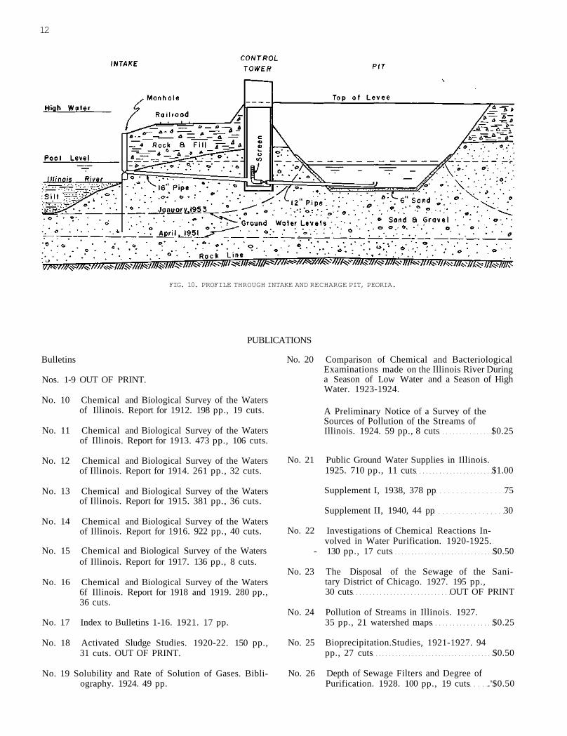
Figure 10. Profile Through Recharge Pit, Peoria 12
FUNCTIONS OF STATE WATER SURVEY
In 1917 the Water Survey became a Division of the State Department of Registration and Education charged with the responsibility of cooperating with state and federal agencies in studying the water resources of Illinois and from time to time to publish reports on its findings. Its present staff consists of 65 technical, research, and administrative workers. Facilities include two new half-million dollar buildings (one in Urbana adjacent to the University engineering campus and another in Peoria), a weather station, and a meteorology laboratory. The Water Survey is organized into five technical subdivisions: chemistry, engineering, hydraulic laboratory, meteorology, and Peoria laboratory.
Primarily the Survey is concerned with the available amounts and chemical quality of water resources in Illinois. Sanitary qualities of water resources and supplies
are determined by the Sanitary Engineering Division of the State Department of Public Health with which the Water Survey closely cooperates.
The Water Survey is also active in developing water use and conservation methods by studying and suggesting possible means of augmenting or replacing sources that are becoming inadequate or depleted and for double or even multiple use of the same water.
From its inception, the Water Survey has cooperated with the University of Illinois in mutual consultation and use of facilities. Survey staff members use to a considerable extent the excellent library facilities of the University, attend many of the Fluid Mechanics and other University technical panels, and have now secured the services of Professor J. M. Robertson on a part-time basis as advisor for hydraulics research.
HISTORY OF THE STATE WATER SURVEY
Due to increasingly serious typhoid epidemics, in 1895 the University of Illinois was assigned the responsibility of making chemical analyses of waters throughout the state. From this early analytical work, which marked the beginning of the State Water Survey, has grown an organization of some fifty scientists recognized in their respective fields.
Under the direction of the first Survey chief, Dr. Edward R. Bartow, now professor emeritus and former head of the Iowa State University chemistry department, the Water Survey in 1919 pioneered in developing in this country the activated sludge process, a new method of sewage treatment. Continued by Dr. A. M. Buswell, the present chief, appointed in 1920, this program was expanded to include fundamental research in the production of methane from wastes and resulted in various publications which have become standard references in the field.
During the past fifteen years the chemical work has shifted in emphasis to research in water softening, water quality needed by industry, and causes and prevention of corrosion, and the supervision of boiler feedwater treatment at state institutions.
The engineering phase began with a compilation of the first inventory of state municipal ground water supplies, which was published in 1925 as Bulletin 21. During this study the late George C. Habermeyer, then chief engineer, originated methods of determining water levels in wells and set the pattern now used for making well tests. This inventory (brought up to date in 1950 as Bulletin 40) provides basic information to engineers and
well drillers for the development of new or supplemental ground water supplies in the state.
At the same time, stream gaging studies were initiated in cooperation with the United States Geological Survey to obtain continuing records of available surface waters, the major source of water supply in Illinois.
The serious drought of 1936 combined with tremendous industrial expansion during the Second World War resulted in water recessions in vital industrial areas of the state. Studies were made to find ways to alleviate the difficult)'. The most critical water shortage had developed at Peoria, and here, the Water Survey in cooperation with Peoria industry undertook one of its major research projects - artificial recharge of groundwater. The progress of this work is being watched with extreme interest by engineers, especially those who may be called upon for assistance when such shortages occur elsewhere.
Continued heavy demands for water after World War II led to studies in loss of capacity by sedimentation in municipal reservoirs, municipal well mortality, and evaluation of water use and water resources in Illinois.
In 1947, the Water Survey initiated a meteorologic program to study the rainfall resources of the state by use of radar. Incidental to this work, in 1953, the first known radar photographs of the growth and decay of a tornado were made.
Most recently, upon completion of its hydraulic research facilities, the Survey began development work on the hydraulic design of drop-inlet spillways. This type of spillway is becoming more and more in demand for use on recreational lakes, municipal reservoirs, and farm ponds.
HYDRAULIC LABORATORY RESEARCH FACILITIES
Urbana Hydraulic Laboratory
Location
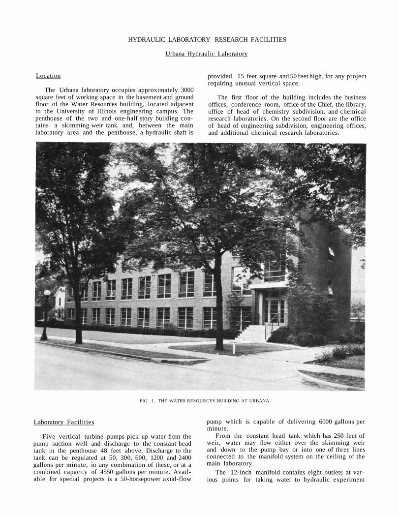
The Urbana laboratory occupies approximately 3000 square feet of working space in the basement and ground floor of the Water Resources building, located adjacent to the University of Illinois engineering campus. The penthouse of the two and one-half story building contains a skimming weir tank and, between the main laboratory area and the penthouse, a hydraulic shaft is
provided, 15 feet square and 50 feet high, for any project requiring unusual vertical space.
The first floor of the building includes the business offices, conference room, office of the Chief, the library, office of head of chemistry subdivision, and chemical research laboratories. On the second floor are the office of head of engineering subdivision, engineering offices, and additional chemical research laboratories.
FIG. 1. THE WATER RESOURCES BUILDING AT URBANA.
Laboratory Facilities
Five vertical turbine pumps pick up water from the pump suction well and discharge to the constant head tank in the penthouse 48 feet above. Discharge to the tank can be regulated at 50, 300, 600, 1200 and 2400 gallons per minute, in any combination of these, or at a combined capacity of 4550 gallons per minute. Available for special projects is a 50-horsepower axial-flow
pump which is capable of delivering 6000 gallons per minute.
From the constant head tank which has 250 feet of weir, water may flow either over the skimming weir and down to the pump bay or into one of three lines connected to the manifold system on the ceiling of the main laboratory.
The 12-inch manifold contains eight outlets at various points for taking water to hydraulic experiment
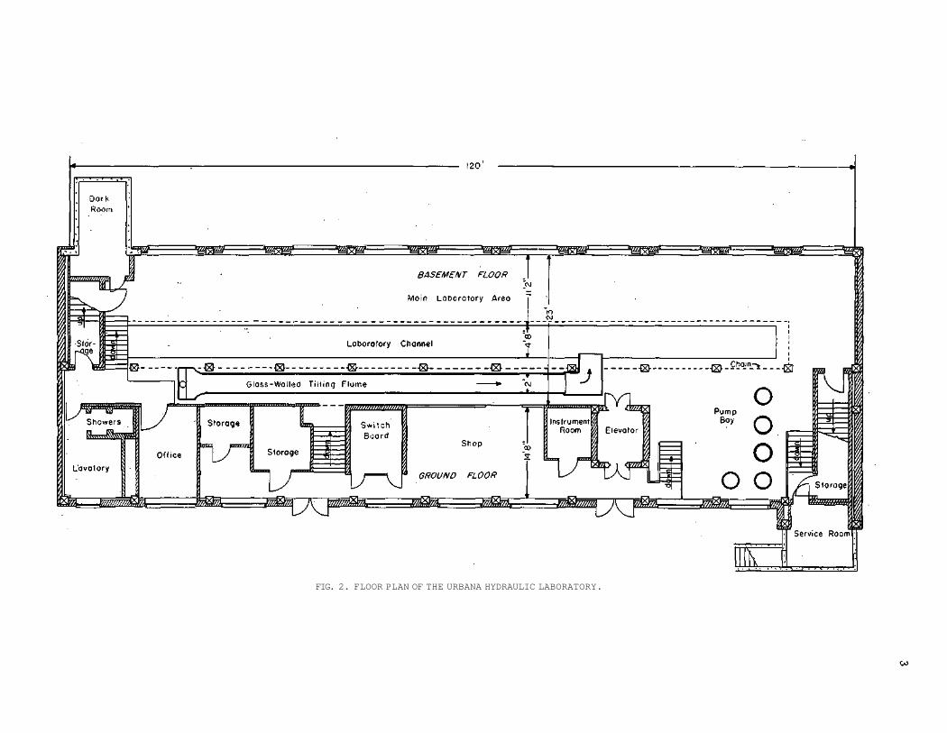
FIG. 2. FLOOR PLAN OF THE URBANA HYDRAULIC LABORATORY.

4
models. Water from the models discharges into the 4 by 4 feet-drainage channel which in turn flows into the pump suction well to allow recirculation.
The drainage channel is divided by a removable partition to form a large volumetric tank. By measuring the level rise in this tank for a given period of time, the discharge from the instrument calibration setup or model may be determined. An isometric view, (Figure 5) shows the layout and important components of the recirculation system.
Laboratory facilities enable the measurement of flow rates by several different methods. For rates above three second-feet, three "short nozzles," calibrated in place in the recirculation system, are used. For rates less than three second-feet, a variety of calibrated orifices and weirs are available. Rates of discharge less than 0.005 second-feet are measured gravimetrically.
FIG. 3. FOUR OF THE FIVE VERTICAL TURBINE PUMPS
AT THE URBANA LABORATORY.
Glass-Walled Tilting Flume
An unusual glass-walled tilting flume has recently been installed at the Urbana laboratory for research in open channel flow and sediment transport.
This versatile research tool can be used for study of flow patterns and relative velocities, flow nets at the approach to weirs, flow in the vicinity of obstructions such as bridge piers or baffle plates, flow through porous media such as earthen dams or filters, seepage pressures under hydraulic structures, erosion and gully preventive measures, the effect of nappe aeration on the discharge characteristics of weirs, hydraulic jumps in sloping channels, sediment samplers, and calibration of laboratory and field instruments.
Almost 93 per cent of the wall area of the nearly 59-foot flume is glass (Figure 6). Maximum deflection of
0.035 inches under full live load has been achieved by mounting the structure on two 60-foot, 24 WF 84 beams. Flows as great as 10 second-feet can be handled at bed slopes of zero to four per cent.
At the upstream end of the flume, clear or sediment-laden water discharges into a steel-plate stilling basin. From here the water flows through corrugated stilling baffles into the transition section which is designed to effect uniform flow to the entrance and to test sections downstream.
The four-foot depth terminates eleven feet from the downstream end of the transition section, leaving approximately forty feet of test section, two feet deep. Sluice gates are provided at the downstream ends of both the entrance and test sections so that hydraulic jump, submerged orifice flow, weir flow, etc., may be studied.
Other Research Facilities
The laboratory also has compressed air, vacuum, and high and low pressure steam lines. There is a fully-equipped photographic darkroom in the basement area, including camera and floodlights, and a machine shop on the ground floor.
Current Laboratory Research
Drop-Inlet Spillway. Dwindling water supplies due to drought conditions and to increased water use have focused attention on the value of small reservoirs, most of which make use of a structure known as the drop-inlet spillway. Last year, more than twenty of these reservoirs or farm ponds were constructed in one Illinois county alone. Since for the small farmer the cost of such a structure might be prohibitive, research is now being done to develop an economical, efficient design.
Dielectric Constant of Water. This project was initiated to measure changes in the dielectric constant of water as flow becomes increasingly turbulent. Such a change would indicate a stretching of molecular bonds and shed new light on unexplained features of the mechanics of turbulence. Current results have shown that the change in dielectric constant, if it exists, is less than one per cent for the maximum turbulence obtained. Continued study with larger scale equipment might possibly indicate a more accurate relationship between the dielectric constant change and turbulence.
Flow Through Granular Media. Related to this work is a study of the Fair-Hatch equation for the analysis of flow through granular media. Preliminary work on the study, which was initiated in 1951, was reported at the Second Midwestern Conference on Fluid Mechanics at Ohio State University. The study aims to develop a method for calculating frictional losses when the flow is in transition between the laminar state and complete tubulence.
Bubbler System Measurement of Water Levels. Since Survey work requires the measurement of minute changes in water levels during pumping tests, an adaptation of the bubbler-system was developed for greater precision. The former instrumentation was studied, modified to correct inherent errors, tested and compared with other methods. The new instrumentation has proved more ac-
5
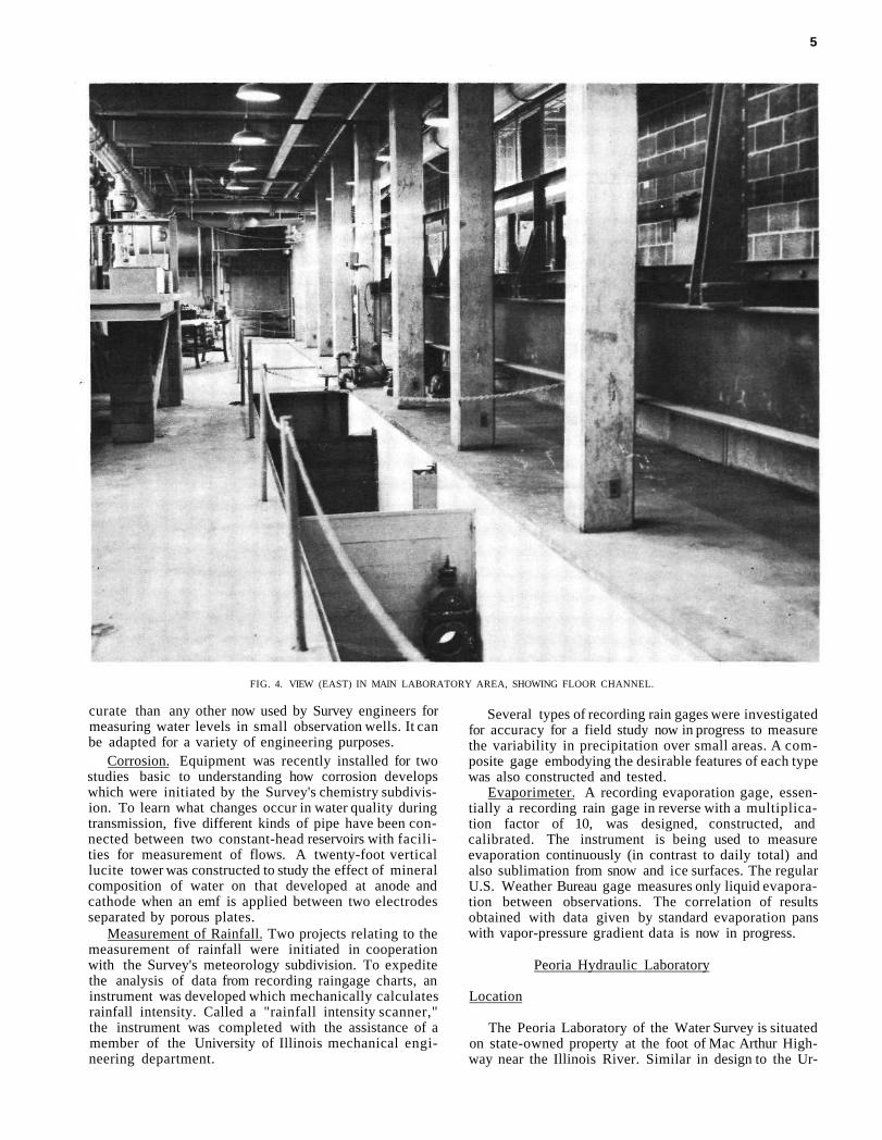
FIG. 4. VIEW (EAST) IN MAIN LABORATORY AREA, SHOWING FLOOR CHANNEL.
curate than any other now used by Survey engineers for measuring water levels in small observation wells. It can be adapted for a variety of engineering purposes.
Corrosion. Equipment was recently installed for two studies basic to understanding how corrosion develops which were initiated by the Survey's chemistry subdivision. To learn what changes occur in water quality during transmission, five different kinds of pipe have been connected between two constant-head reservoirs with facilities for measurement of flows. A twenty-foot vertical lucite tower was constructed to study the effect of mineral composition of water on that developed at anode and cathode when an emf is applied between two electrodes separated by porous plates.
Measurement of Rainfall. Two projects relating to the measurement of rainfall were initiated in cooperation with the Survey's meteorology subdivision. To expedite the analysis of data from recording raingage charts, an instrument was developed which mechanically calculates rainfall intensity. Called a "rainfall intensity scanner," the instrument was completed with the assistance of a member of the University of Illinois mechanical engineering department.
Several types of recording rain gages were investigated for accuracy for a field study now in progress to measure the variability in precipitation over small areas. A composite gage embodying the desirable features of each type was also constructed and tested.
Evaporimeter. A recording evaporation gage, essentially a recording rain gage in reverse with a multiplication factor of 10, was designed, constructed, and calibrated. The instrument is being used to measure evaporation continuously (in contrast to daily total) and also sublimation from snow and ice surfaces. The regular U.S. Weather Bureau gage measures only liquid evaporation between observations. The correlation of results obtained with data given by standard evaporation pans with vapor-pressure gradient data is now in progress.
Peoria Hydraulic Laboratory
Location
The Peoria Laboratory of the Water Survey is situated on state-owned property at the foot of Mac Arthur Highway near the Illinois River. Similar in design to the Ur-
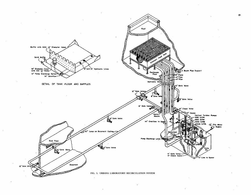
FIG. 5. URBANA LABORATORY RECIRCULATION SYSTEM

FIG. 6. LAYOUT. OF GLASS-WALLED TILTING FLUME

GO
FIG. 7 LOCATION OF WATER RESOURCES BUILDING, URBANA
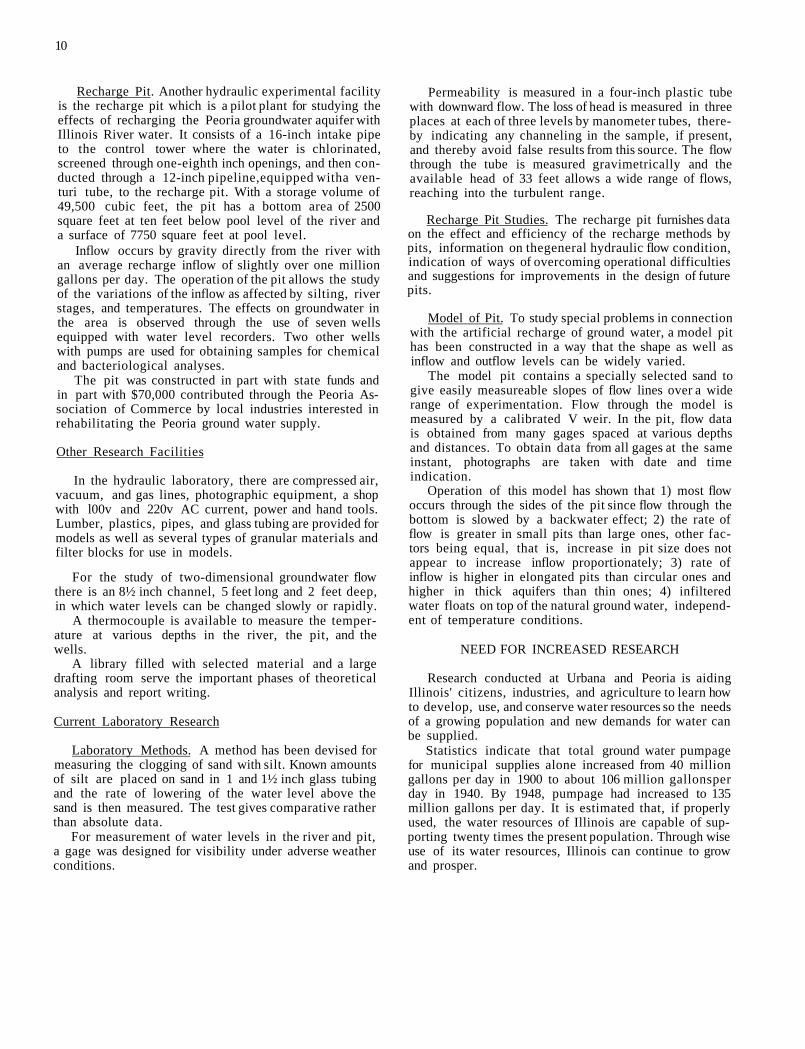
bana building but proportionately smaller, the Peoria building has three floors and a penthouse. The ground floor or basement contains the hydraulic laboratory, machine shop, dark room, small office, and four utility rooms. The main offices and the chemical and bacteriological laboratories are on the first floor; and the engineering offices, drafting room, and library, on the second.
Recirculation System
The hydraulic laboratory has its own water supply from a 53-foot well with a 25 gallons per minute pump delivering make-up water into an underground tank of 7300 gallons capacity. From this tank, the water is lifted by 50, 200, 400 and 800 gallons per minute pumps into the 1800 gallon constant level tank in the penthouse.
The sizes of the three large pumps were selected to obtain a full range of pumping in 200 gallons per minute intervals from 200 to 1400 gallons per minute. The con-
9
stant level tank has 48 feet of weir length which produced only an eighth inch rise in overflow level when the 800 gallons per minute pump is added to the others.
Three 6-inch lines bring water from the constant level tank to a 10-inch service line around the main part of the hydraulic laboratory in the basement. The latter line is arranged in such a way that three separate sections can be valved off and fed independently. Thus, it is possible to shut off one experiment without affecting flow to other experiments in progress.
Separate two-inch lines provide water to experiments conducted on the first and second floors. Any used water that is clean is returned to the pump pit through a two-foot wide channel in the basement floor. Waste water goes into the sewer through floor drains.
Figure 9 shows a diagram of the piping for the hydraulic laboratory. The recirculating system is independent from the sanitary water supply of the building, however it can also be used to fill all tanks.
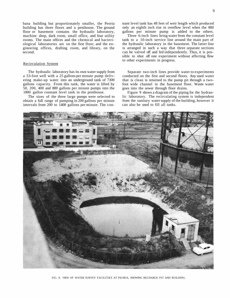
FIG. 8. VIEW OF WATER SURVEY FACILITIES AT PEORIA, SHOWING RECHARGE PIT AND BUILDING.
10
Recharge Pit. Another hydraulic experimental facility is the recharge pit which is a pilot plant for studying the effects of recharging the Peoria groundwater aquifer with Illinois River water. It consists of a 16-inch intake pipe to the control tower where the water is chlorinated, screened through one-eighth inch openings, and then conducted through a 12-inch pipeline,equipped witha ven-turi tube, to the recharge pit. With a storage volume of 49,500 cubic feet, the pit has a bottom area of 2500 square feet at ten feet below pool level of the river and a surface of 7750 square feet at pool level.
Inflow occurs by gravity directly from the river with an average recharge inflow of slightly over one million gallons per day. The operation of the pit allows the study of the variations of the inflow as affected by silting, river stages, and temperatures. The effects on groundwater in the area is observed through the use of seven wells equipped with water level recorders. Two other wells with pumps are used for obtaining samples for chemical and bacteriological analyses.
The pit was constructed in part with state funds and in part with $70,000 contributed through the Peoria Association of Commerce by local industries interested in rehabilitating the Peoria ground water supply.
Other Research Facilities
In the hydraulic laboratory, there are compressed air, vacuum, and gas lines, photographic equipment, a shop with l00v and 220v AC current, power and hand tools. Lumber, plastics, pipes, and glass tubing are provided for models as well as several types of granular materials and filter blocks for use in models.
For the study of two-dimensional groundwater flow there is an 8½ inch channel, 5 feet long and 2 feet deep, in which water levels can be changed slowly or rapidly.
A thermocouple is available to measure the temperature at various depths in the river, the pit, and the wells.
A library filled with selected material and a large drafting room serve the important phases of theoretical analysis and report writing.
Current Laboratory Research
Laboratory Methods. A method has been devised for measuring the clogging of sand with silt. Known amounts of silt are placed on sand in 1 and 1½ inch glass tubing and the rate of lowering of the water level above the sand is then measured. The test gives comparative rather than absolute data.
For measurement of water levels in the river and pit, a gage was designed for visibility under adverse weather conditions.
Permeability is measured in a four-inch plastic tube with downward flow. The loss of head is measured in three places at each of three levels by manometer tubes, thereby indicating any channeling in the sample, if present, and thereby avoid false results from this source. The flow through the tube is measured gravimetrically and the available head of 33 feet allows a wide range of flows, reaching into the turbulent range.
Recharge Pit Studies. The recharge pit furnishes data on the effect and efficiency of the recharge methods by pits, information on thegeneral hydraulic flow condition, indication of ways of overcoming operational difficulties and suggestions for improvements in the design of future pits.
Model of Pit. To study special problems in connection with the artificial recharge of ground water, a model pit has been constructed in a way that the shape as well as inflow and outflow levels can be widely varied.
The model pit contains a specially selected sand to give easily measureable slopes of flow lines over a wide range of experimentation. Flow through the model is measured by a calibrated V weir. In the pit, flow data is obtained from many gages spaced at various depths and distances. To obtain data from all gages at the same instant, photographs are taken with date and time indication.
Operation of this model has shown that 1) most flow occurs through the sides of the pit since flow through the bottom is slowed by a backwater effect; 2) the rate of flow is greater in small pits than large ones, other factors being equal, that is, increase in pit size does not appear to increase inflow proportionately; 3) rate of inflow is higher in elongated pits than circular ones and higher in thick aquifers than thin ones; 4) infiltered water floats on top of the natural ground water, independent of temperature conditions.
NEED FOR INCREASED RESEARCH
Research conducted at Urbana and Peoria is aiding Illinois' citizens, industries, and agriculture to learn how to develop, use, and conserve water resources so the needs of a growing population and new demands for water can be supplied.
Statistics indicate that total ground water pumpage for municipal supplies alone increased from 40 million gallons per day in 1900 to about 106 million gallonsper day in 1940. By 1948, pumpage had increased to 135 million gallons per day. It is estimated that, if properly used, the water resources of Illinois are capable of supporting twenty times the present population. Through wise use of its water resources, Illinois can continue to grow and prosper.
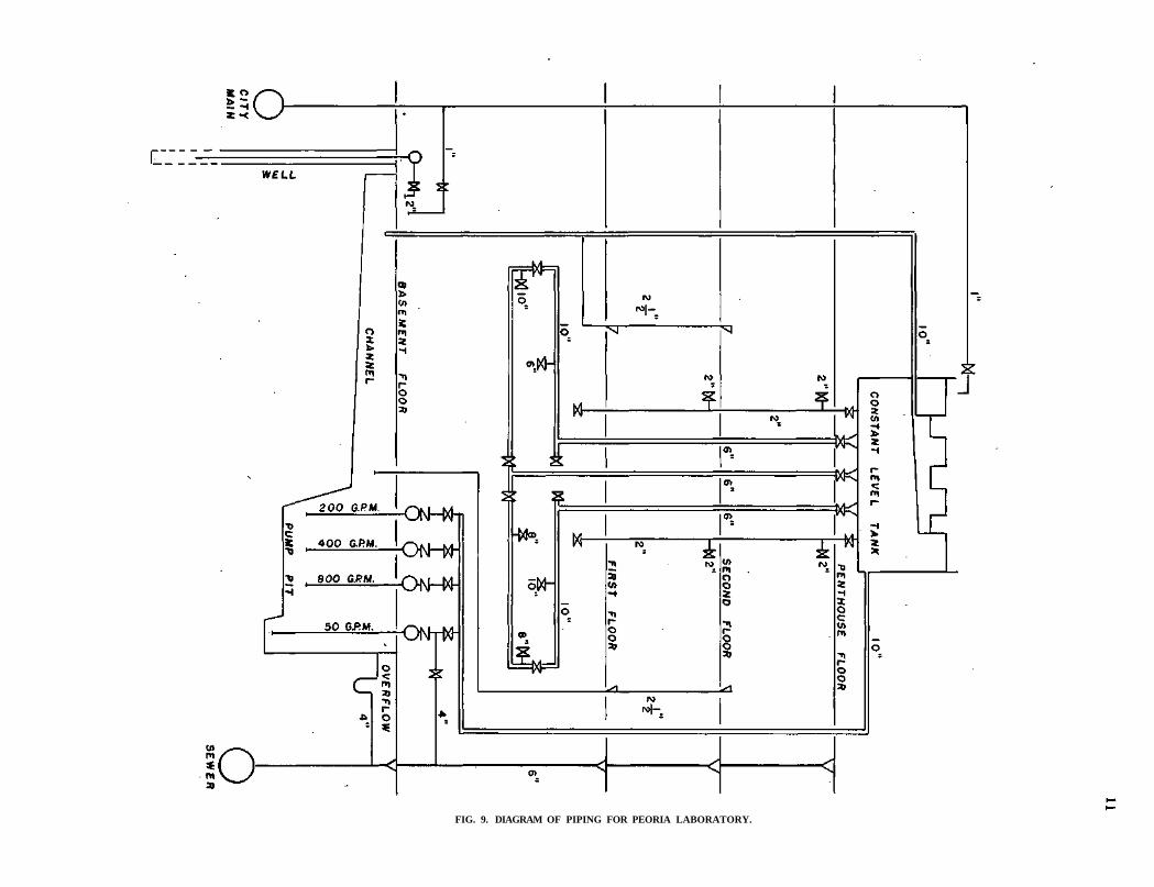
FIG. 9. DIAGRAM OF PIPING FOR PEORIA LABORATORY.
12
FIG. 10. PROFILE THROUGH INTAKE AND RECHARGE PIT, PEORIA.
PUBLICATIONS
Bulletins
Nos. 1-9 OUT OF PRINT.
No. 10 Chemical and Biological Survey of the Waters of Illinois. Report for 1912. 198 pp., 19 cuts.
No. 11 Chemical and Biological Survey of the Waters of Illinois. Report for 1913. 473 pp., 106 cuts.
No. 12 Chemical and Biological Survey of the Waters of Illinois. Report for 1914. 261 pp., 32 cuts.
No. 13 Chemical and Biological Survey of the Waters of Illinois. Report for 1915. 381 pp., 36 cuts.
No. 14 Chemical and Biological Survey of the Waters of Illinois. Report for 1916. 922 pp., 40 cuts.
No. 15 Chemical and Biological Survey of the Waters of Illinois. Report for 1917. 136 pp., 8 cuts.
No. 16 Chemical and Biological Survey of the Waters 6f Illinois. Report for 1918 and 1919. 280 pp., 36 cuts.
No. 17 Index to Bulletins 1-16. 1921. 17 pp.
No. 18 Activated Sludge Studies. 1920-22. 150 pp., 31 cuts. OUT OF PRINT.
No. 19 Solubility and Rate of Solution of Gases. Bibliography. 1924. 49 pp.
No. 20 Comparison of Chemical and Bacteriological Examinations made on the Illinois River During a Season of Low Water and a Season of High Water. 1923-1924.
A Preliminary Notice of a Survey of the Sources of Pollution of the Streams of Illinois. 1924. 59 pp., 8 cuts $0.25
No. 21 Public Ground Water Supplies in Illinois. 1925. 710 pp., 11 cuts $1.00
Supplement I, 1938, 378 pp 75
Supplement II, 1940, 44 pp 30
No. 22 Investigations of Chemical Reactions Involved in Water Purification. 1920-1925.
- 130 pp., 17 cuts $0.50
No. 23 The Disposal of the Sewage of the Sanitary District of Chicago. 1927. 195 pp., 30 cuts OUT OF PRINT
No. 24 Pollution of Streams in Illinois. 1927. 35 pp., 21 watershed maps $0.25
No. 25 Bioprecipitation.Studies, 1921-1927. 94 pp., 27 cuts $0.50
No. 26 Depth of Sewage Filters and Degree of Purification. 1928. 100 pp., 19 cuts .'$0.50

No. 27 A Study of Factors Affecting the Efficiency and Design of Farm Septic Tanks. 1927. 45 pp., 25 cuts $0.50
No. 28 Illinois River Studies, 1925-1928. 127 pp., 15 cuts $0.75
No. 29 Studies on Two-Stage Sludge Digestion, 1928-1929. 92 pp., 27 cuts $0.50
No. 30 Laboratory Studies of Sludge Digestion. 84 pp., 5 cuts $0.50
No. 31 Preliminary Data on Surface Water Resources, 1937. 157 pp $0.50
No. 32 Anaerobic Fermentations. 1939. 193 pp., 25 cuts OUT OF PRINT
No. 33 Water Resources in Peoria-Pekin District, 1940. 114 pp $0.35
No. 34 Sandstone Water Supplies of the Joliet Area, 1941. 128 pp $0.35
No. 35 Ground Water Supplies of the Chicago-Joliet-Chicago Heights Area, 1943. 285 pp $1.00
No. 36 Ground Water Supplies in Northern Cook and Northern DuPage Counties. 1945. 119 pp $0,75
No. 37 The Causes and Effects of Sedimentation in Lake Decatur. 1947. 62 pp $0.60
No. 38 Hydrology of Five Illinois Water Supply Reservoirs. 1948. 260 pp $1.50
No. 39 Ground Water in the Peoria Region. 1950 $1.00
No. 40 Public Ground-Water Supplies in Illinois. 1950 $8.00
No. 41 Proceedings 1951 Conference on Water Resources. 1952 $3.00
No. 42 Water and Land Resources of the Crab Orchard Lake Basin $0.80
Circulars
No. 1 Well Water Recessions in Illinois. By G. C. Habermeyer (1928). OUT OF PRINT.
No. 2 The Effect of Certain Illinois Waters on Lead. By O. W. Rees and A. L. Elder (1928). OUT OF PRINT.
No. 3 Removal of Colloids from Sewage. By A. M. . Buswell, R. A. Shive, and S. L. Neave (1928). OUT OF PRINT.
13
No. 4 Control of Scum in Sewage Tanks. By A. M. Buswell (1929).
No. 5 The Biology of a Sewage Treatment Plant. A Preliminary Survey, Decatur, Illinois. By H. P. K. Agersborg and W. D. Hatfield (1929). OUT OF PRINT.
No. 6 Some Idiosyncrasies of Ground Waters. By W. D. Gerber (1930). OUT OF PRINT.
No. 7 Fermentation Products of Cellulose. By C. S. Boruff and A. M. Buwell (1929).
No. 8 Che'mical Studies on Sludge Digestion. By S. L. Neave with A. M. Buswell (1930).
No. 9 Illinois River Studies, 1929-30. By C. S. Boruff (1930).
No. 10 Production of Fuel Gas by Anaerobic Fermentations. By A. M. Buswell (1930).
No. 11 The Hydrology of Industrial and Municipal Water Supplies in Illinois. By W. D. Gerber (1931).
No. 12 Some Economic Problems of the Illinois River Valley. Papers Presented before the Economics Section of the Illinois State Academy of Science, Peoria, Illinois, May 8, 1931.
No. 13 Soap Usage and Water Hardness. By H. W. Hudson (1934).
No. 14 A Carbon Study of Sludge Digestion. By T. E. Larson, C. S. Boruff and A. M. Buswell (1934).
No. 15 The Determination of Free Chlorine. By D. Tarvin, H. R. Todd, and A. M. Buswell (1935).
No. 16 The Treatment of "Beer Slop" and Similar Wastes. By A. M. Buswell (1935).
No. 17 Data on the Ground Waters of Lake County, Illinois. By W. D. Gerber, S. M. McClure, D. Tarvin, and A. M. Buswell (1935).
No. 18 A Survey of the Ground Water Resources of Illinois. By W. D. Gerber, S. M. McClure, D. Tarvin, and A. M. Buswell (1935).
No. 19 Water Quality for Fire Fighting(The Relations of Water Resistivity to Safe Distance from Nozzle to Electric Lines). By A. M. Buswell (1937).
No. 20 Model Study of Spillway Characteristics, 1935-1937. (A Joint publication by the University of Illinois Engineering Experiment Station and the Illinois State Water Survey Division.) OUT OF PRINT.

14
No. 21 Collected Papers on Water Softening. (1940) OUT OF PRINT.
No. 22 Calcium Carbonate Saturation Index and Alkalinity Interpretations. By T. E. Larson and A. M. Buswell (1943).
No. 23 Rehabilitation of Sandstone Wells. By J. B. Millis (1946). OUT OF PRINT.
No. 24 Corrosion in Vertical Turbine Pumps. By T. E. Larson (1947).
No. 25 Water Treatment for the Small Homes or Farms. By T. E. Larson and H: A. Spafford (1947).
No. 26 Interpretation of Soap Savings Data. By T. E. Larson (1948).
No. 27 Geologic Correlation and Hydrologic Interpretation of Water Analyses. By T. E. Larson
.(1949). OUT OF PRINT.
No. 28 Rainfall Intensity - Frequency Data, Cham-paign-Urbana, Illinois. By G. E. Stout and F. A. Huff (1949). OUT OF PRINT.
No. 29 Chicago Area Water Supply - A Symposium Presented Before the Western Society of Engineers (1950). OUT OF PRINT.
No. 30 Annual Report for 1948-1949. (1950)
No. 31 Mineral Content of Public Groundwater Supplies in Illinois. By T. E. Larson (1951).
No. 32 Water Resource Conservation in Illinois. By H. E. Hudson, Jr. (1950).
No. 33 Residential Water Use and Family Income. By B. O. Larson and H. E. Hudson, Jr. (1951).
No. 34 . A Preliminary Study of Atmospheric Moisture-Precipitation Relationships over Illinois. (1951) OUT OF PRINT.
No. 35 The Ideal Lime Softened Water. By T. E. Larson. (1951)
No. 36 Getting The Facts Through Surveys and Investigations. By H. E. Hudson, Jr. and J. B. Stall. (1952).
No. 37 Mortality Experience with Illinois Municipal Wells. By H. E. Hudson, Jr. and J. L. Geils (1952).
No. 38 Determination of Transmissibility and Storage Coefficients from Pumping Test Data. By Ven Te Chow. (1952).
No. 39 Area-Depth Studies for Thunderstorm Rainfall in Illinois. By F. A. Huff and G. E. Stout. (1952).
No. 40 Hardness Reduction vs. Removal, A Critical Evaluation. By T. E. Larson. (1952).
No. 41 Feed Water Treatment at the Illinois State Institutions. By R. W. Lane. (1952).
No. 42 Municipal and Home Water Softening. By T. E. Larson. (1953).
No. 43 Evaporation Records in Illinois. By W. J. Roberts. (1954).
No. 44 Gravel Packing Water Wells. By Harman F. Smith. (1954). ,
No. 45 Corrosion by Water at Low Flow Velocity. By T. E. Larson and R. M. King. (1954).
No. 46 Quantitative Measurement of Rainfall by Radar. By A. M. Buswell, G. E. Stout and J. C. Neill. (1954).
No. 47 Hydrogen Exchange Resin for Steam Purity Analysis. By R. W. Lane, T. E. Larson, J. W. Pankey. (1955).
Reports of Investigations
No. 1 Temperature and Turbidity of Some River Waters in Illinois. By Max Suter (1948).
No. 2 Groundwater Resources in Winnebago County, with Specific Reference to Conditions at Rock-ford. By H. F. Smith and T. E. Larson (1948).
No. 3 Radar and Rainfall. By G. E. Stout and F. A. Huff (1949). OUT OF PRINT.
No. 4 The Silt Problem of Spring Lake, Macomb, Illinois. By J. B. Stall, L. C. Gottschalk. A. A. Klingebiel, E. L. Sauer, and E. E. DeTurk (1949). OUT OF PRINT.
No. 5 Infiltration of Soils in the Peoria Area. By G. A. Stauffer (1949).
No. 6 Groundwater Resources in Champaign County. By H. F. Smith (1950).
No. 7 The Silting of Ridge Lake, Fox Ridge State Park, Charleston, Illinois. By J. B. Stall, L. C. Gottschalk, A. A. Klingebiel, E. L. Sauer and S. W. Melsted (1951). OUT OF PRINT.
No. 8 The Silting of Lake Chautauqua, Havana, Illinois, By J. B. Stall and S. W. Melsted (1951).

No. 9 The Silting of Carbondale Reservoir, Carbon-dale, Illinois. By B. O. Larson, A. A. Klinge-biel, E. L. Sauer, S. W. Melsted, and R. C. Hay (1951). OUT OF PRINT.
No. 10 The Silting of Lake Bracken, Galesburg, Illinois. By B. O. Larson, A. A. Klingebiel, E. L. Sauer, and S. W. Melsted (1951).
No. 11 Irrigation in Illinois. By W. J. Roberts (1951).
No. 12 The Silting of West Frankfort Reservoir, West Frankfort, Illinois. By J. B. Stall, A. A. Klingebiel, S. W. Melsted, and E. L. Sauer (1951).
No. 13 Studies of Thunderstorm Rainfall with Dense Raingage Networks and Radar. (1951) OUT OF PRINT.
No. 14 The Storm of July 8, 1951 in North Central Illinois. (1952).
No. 15 The Silting of Lake Calhoun, Galva, Illinois. By J. B. Stall, A. A. Klingebiel, S. A. Melsted and E. L. Sauer (1952).
15
No. 16 The Silting of Lake Springfield, Springfield, Illinois. By J. B. Stall, L. C. Gottschalk, and H. M. Smith (1952).
No. 17 Preliminary Investigation of Groundwater Resources in the American Bottom. By Jack Bruin and H. F. Smith (1953).
No. 18 The Silting of Lake Carthage, Carthage, Illinois. By J. B. Stall, G. R. Hall, S. W. Melsted and E. L. Sauer (1953).
No. 19 Rainfall-Radar Studies of 1951. By G. E. Stout, J. C. Neill, and G. W. Famsworth (1953).
No. 20 Precipitation Measurements Study. By John C. Kurtyka (1953). OUT OF PRINT.
No. 21 Analysis of 1952 Radar and Raingage Data. By J. C. Neill (1953).
No. 22 Study of an Illinois Tornado Using Radar, Synoptic Weather and Field Survey Data. By F. A. Huff, H. W.HiserandS.G. Bigler (1954).