Circular Microphone Array for Discrete Multichannel...
14
AUDIO ES R Audio Engineering Society Convention Paper 5716 Presented at the 114th Convention 2003 March 22–25 Amsterdam, The Netherlands This convention paper has been reproduced from the author’s advance manuscript, without editing, corrections, or consideration by the Review Board. The AES takes no responsibility for the contents. Additional papers may be obtained by sending request and remittance to Audio Engineering Society, 60 East 42nd Street, New York, New York 10165-2520, USA; also see www.aes.org. All rights reserved. Reproduction of this paper, or any portion thereof, is not permitted without direct permission from the Journal of the Audio Engineering Society. Circular microphone array for discrete multichannel audio recording. Edo Hulsebos 1 , Thomas Schuurmans 1 , Diemer de Vries 1 , Rinus Boone 1 1 Laboratory of Acoustical Imaging and Sound Control, Delft University of Technology, P.O.B. 5046, 2600 GA Delft, The Netherlands Correspondence should be addressed to Edo Hulsebos ([email protected]) ABSTRACT Traditional stereo microphone pair techniques for natural recording are quite capable for 2 channel stereo reproduction. However, for multichannel reproduction systems like 5.1, 7.1, ambisonics and Wave Field Synthesis compromises in terms of coverage, source localization and channel separation are unavoidable. The main reason for this is that micro- phones currently used only have low order directivity patterns (omni, figure-of eight, cardioid or hypercardioid) that cannot provide sufficient angular resolution to avoid unwanted cross talk between the recording channels. In this paper a discrete coincident 12 channel microphone is proposed in order to solve these problems. This microphone consists of a circular array with a radius of 1 meter using 288 microphone capsules whose output signals are combined into 24 channels using simple analog electronics. These 24 channels are captured using a multi-track computer interface and post-processed into up to 12 discrete reproduction audio channels.
Transcript of Circular Microphone Array for Discrete Multichannel...

A U D I O
ESR
Audio Engineering Society
Convention Paper 5716Presented at the 114th Convention
2003 March 22–25 Amsterdam, The Netherlands
This convention paper has been reproduced from the author’s advance manuscript, without editing, corrections, orconsideration by the Review Board. The AES takes no responsibility for the contents. Additional papers may beobtained by sending request and remittance to Audio Engineering Society, 60 East 42nd Street, New York, New York10165-2520, USA; also seewww.aes.org . All rights reserved. Reproduction of this paper, or any portion thereof,is not permitted without direct permission from theJournal of the Audio Engineering Society.
Circular microphone array for discretemultichannel audio recording.
Edo Hulsebos1, Thomas Schuurmans1, Diemer de Vries1, Rinus Boone1
1Laboratory of Acoustical Imaging and Sound Control, Delft University of Technology, P.O.B. 5046, 2600 GA Delft, The Netherlands
Correspondence should be addressed to Edo Hulsebos ([email protected] )
ABSTRACTTraditional stereo microphone pair techniques for natural recording are quite capable for 2 channel stereo reproduction.However, for multichannel reproduction systems like 5.1, 7.1, ambisonics and Wave Field Synthesis compromises interms of coverage, source localization and channel separation are unavoidable. The main reason for this is that micro-phones currently used only have low order directivity patterns (omni, figure-of eight, cardioid or hypercardioid) thatcannot provide sufficient angular resolution to avoid unwanted cross talk between the recording channels. In this papera discrete coincident 12 channel microphone is proposed in order to solve these problems. This microphone consistsof a circular array with a radius of 1 meter using 288 microphone capsules whose output signals are combined into 24channels using simple analog electronics. These 24 channels are captured using a multi-track computer interface andpost-processed into up to 12 discrete reproduction audio channels.
HULSEBOS ET AL. CIRCULAR MICROPHONE ARRAY FOR AUDIO RECORDING
INTRODUCTION
In previous AES conventions, papers were presented by the firstauthor on the subject of circular microphone arrays. In preprint5337 of the 110th AES convention in Amsterdam, which waspublished in a slightly modified form in the October 2002 issueof the AES journal, an elegant method was described to decom-pose the sound field measured on a circular array in terms of in-coming and outgoing cylindrical harmonic solutions of the 2Dwave equation [1,2]. These cylindrical harmonics were shownto be very closely related to the plane wave decomposition, adescription of the sound field that proved very useful for au-ralization purposes. In preprint 5579 presented at the 112thAES convention in Munich the theory for circular arrays wasextended to focusing and spatial filtering to control aperture[3]. Furthermore it was shown that it is possible to simulatevirtual microphones with any desired directivity properties inpost-processing which is not possible with currently availablesingle microphones.
Until now the circular array was only used for impulse responsemeasurements. A single microphone mounted by means of arod on a slowly rotating turntable was sufficient for this pur-pose. In this paper, however, the focus is on building a full ar-ray, which can also be used for live audio recording purposes.A number of virtual microphones is created on the array havingwell controlled high order directivity patterns to deliver a largenumber of discrete output channels without any unnecessarycrosstalk between them.
A prototype array is designed to deliver up to 12 discrete co-incident channels of audio with good channel separation downto 100 Hz and a spatial aliasing frequency above 15 kHz. Toachieve this a circle with a radius of 1 meter and 288 small car-dioid microphones is used. The high number of microphonesis not a big problem in this case; various cheap and reason-able quality capsules are available on the market. The prob-lem, however, is the number of acquisition channels. In thispaper a solution for this problem is given, reducing the numberof required acquisition channels from 288 to only 24 for a 12channel microphone array.
WAVE DECOMPOSITION
If on the circular array both pressure and normal particle ve-locity are recorded, the approach is to decompose the recordedsound field into cylindrical harmonics:
M(1)(kθ , ω) =
H ′(2)kθ
(k R)P(kθ , ω) − H (2)kθ
(k R) jρcVn(kθ , ω)
H (1)kθ
(k R)H ′(2)kθ
(k R) − H (2)kθ
(k R)H ′(1)kθ
(k R)
M(2)(kθ , ω) =
H ′(1)kθ
(k R)P(kθ , ω) − H (1)kθ
(k R) jρcVn(kθ , ω)
H (2)kθ
(k R)H ′(1)kθ
(k R) − H (1)kθ
(k R)H ′(2)kθ
(k R)
(1)
In these equationsM(1) andM(2) are the incoming and out-going cylindrical harmonic decompositions of the sound field,P(kθ , ω) and Vn(kθ , ω) are the spatial and temporal Fouriertransforms of the pressurep(θ, t) and normal velocityvn(θ, t)measured on a circular array with radiusR, k = ω/c is thetemporal wave number,kθ = . . . , −1, 0, 1, . . . is the angular
wave number andH (1,2)kθ
are the Hankel functions of the firstand second kind [4]. See [3] for more details on the cylindricalharmonic decomposition. Since in normal recording situationsall sound waves are coming from the exterior of the circle, onlythe incoming partM(1) needs to be considered. The planewave decomposition can easily be calculated fromM(1) using
s∞(θ, ω) =1
2π
∑kθ
j (1−kθ )M(1)(kθ , ω)ejkθ θ , (2)
which is up to a rotation factorj (1−kθ ) equal to the inverseFourier transform ofM(1) [1,2]. Instead of using both pres-sure and normal particle velocity, it is sufficient to record thesound field on the array using outward pointing cardioid mi-crophones. Using only omnidirectional or only figure-of-eightmicrophones is not sufficient though; not all cylindrical har-monics can be obtained from such a recording. In equation (1)it is found that the cylindrical harmonics are proportional to the2-dimensional Fourier transform components of the recordedsound field. In figure 1 the amplitudes for the 2D Fourier trans-forms of a plane wave recorded on a circular array using om-nis, figure-of-eights and cardioid are shown. The omni andfigure-of-eight recordings from figure 1(a) and (b) both havezeros in their Fourier transform components and therefore can-not be used separately for a calculation of the non-zero cylin-drical harmonic components of the plane wave shown in fig-ure 2. However, since the zero components for the omni and thefigure-of-eight microphone arrays occur at different frequencycomponents, they can be used together for a proper cylindri-cal harmonic decomposition as is done in equation (1). For thecardioid case the 2D Fourier transform components are alreadyfree from zeros and can easily be used for this purpose as well.This way the number of acquisition channels can be reducedby a factor 2. Note however that it is not possible to separatebetween incoming and outgoing sound waves when using onlyone set of outward pointing cardioids. Also equation (1) and (2)cannot be used directly in this case, but the appropriate planewave decomposition operator can easily be calculated numeri-cally by creating an inverse for the 2D Fourier transform of aplane Dirac wave simulated on a cardioid array.
VIRTUAL MICROPHONES
In this paper the aim is to deliver 12 discrete coincident chan-nels of audio. For that purpose 12 virtual microphones withsuitable directivity characteristics can be created by combiningthe appropriate cylindrical harmonic components with appro-priate weighting factors. The only limitation in creating vir-
AES 114TH CONVENTION, AMSTERDAM, THE NETHERLANDS, 2003 MARCH 22–25 2

HULSEBOS ET AL. CIRCULAR MICROPHONE ARRAY FOR AUDIO RECORDING
multipole number (o−1)
freq
uenc
y (k
Hz)
(a) Omni
−60 −40 −20 0 20 40 60
0
0.5
1
1.5
2
2.5
3
3.5
4
multipole number (o−1)
freq
uenc
y (k
Hz)
(b) Figure−of−eight
−60 −40 −20 0 20 40 60
0
0.5
1
1.5
2
2.5
3
3.5
4
multipole number (o−1)
freq
uenc
y (k
Hz)
(c) Cardioid
−60 −40 −20 0 20 40 60
0
0.5
1
1.5
2
2.5
3
3.5
4
Figure 1: 2D Fourier transform of a simulated circular plane wave recording, using omni, figure-of-eight and cardioid microphones
tual microphones is that the directivity pattern of the virtualmicrophone cannot contain cylindrical harmonics with spatialfrequencieskθ beyond the angular resolution available for thegiven array size. Notice that the maximal available angular fre-quency component is proportional to the radius (aperture) ofthe circular array and the temporal frequency as can be seen infigure 1. In practice this usually means that for high temporalfrequencies the created virtual microphones will match the de-sired directivity pattern perfectly, but below a certain temporalfrequency the highest angular frequency components in the de-sired directivity pattern are missing. The value of this temporalcutoff frequency depends on the radius of the circular array andthe sharpness of the desired directivity pattern. The sharper itis, the higher the maximal required angular frequency are andthe higher the temporal cutoff frequency will be.
Virtual microphones can be created easily using the plane wavedecomposition. The plane wave decomposition can be con-sidered as a set virtual microphone responses, which have themaximal directivity sharpness that can possibly be obtained forthe given microphone array aperture. Supposes∞(θ, ω) is theplane wave decomposition of a sound field andd(θ, ω) is thepossibly frequency dependent (in this paper only frequency in-dependent directivity patterns are used though) desired direc-tivity pattern of a virtual microphone. Then the output of thevirtual microphone can be obtained from the plane wave de-composition using
O(w) =
∑θ
d(θ, ω) · s∞(θ, ω) (3)
The actual obtained directivity patterndc(θ, ω) of the virtualmicrophone is given by
Dc(kθ , ω) = D(kθ , ω) · Splane(kθ , ω), (4)
whereDc(kθ , ω) and D(kθ , ω) are the angular Fourier trans-form of dc(θ, ω) andd(θ, ω), respectively, andSplane(kθ , ω) is
the 2D Fourier transform of the plane wave decomposition of aplane Dirac wave with angle of incidence equal to zero and ar-riving at the center of the circle att = 0, which is limited in an-gular resolution by the radius of the circular array.Splane(kθ , ω)
for a circle with a 1 meter radius is shown in figure 2. The actual
multipole number (o−1)
freq
uenc
y (k
Hz)
−60 −40 −20 0 20 40 60
0
0.5
1
1.5
2
2.5
3
3.5
4
Figure 2: Cylindrical harmonics decomposition for a circulararray with a 1 meter radius.
directivity pattern is thus a band limited version of the desireddirectivity pattern in terms of the angle. See figure 3(a) for anexample of one of the desired directivity patterns that can beused for obtaining 12 discrete audio channels. The realized di-rectivity pattern using a 288 microphone circular array with aradius of 1 meter is shown in figure 3(b). Notice that apart fromthe angular bandwidth limitation starts taking place at 250 Hz,also spatial aliasing artifacts occur above 15 kHz. These aredetermined by the distance between the microphones and canbe avoided by using even more closely spaced microphones.
AES 114TH CONVENTION, AMSTERDAM, THE NETHERLANDS, 2003 MARCH 22–25 3

HULSEBOS ET AL. CIRCULAR MICROPHONE ARRAY FOR AUDIO RECORDING
Figure 3: Directivity pattern of a virtual microphone created using a 1 meter radius array.
ANALOG PREPROCESSING
The number of microphones used in the circular recording ar-ray is not a big problem as mentioned before; various cheapand reasonable quality capsules are available on the market.The problem however, which is going to be solved next, is thenumber of acquisition channels. A wave decomposition has tobe calculated from all the 288 microphone signals, which mustbe done in the digital domain using 2D Fast Fourier transformalgorithms. This means that 288 microphones need to be digi-tally acquired and processed in real time, something which isn’tfeasible in practice or at least very expensive.
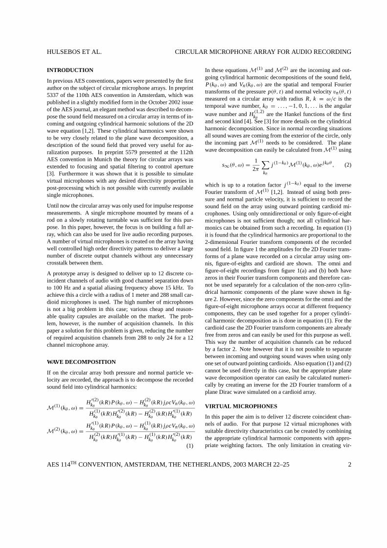
In order to understand how this problem can be solved easilyby drastically reducing the number of acquisition channels, acloser look at the processing scheme is required. See figure 4.In figure 4(a) a circular recording of a plane wave is shown. The2D Fourier transform for this recorded wave is then calculatedand the amplitudes of these complex components are shown infigure 4(b). From this 2D Fourier transform the cylindrical har-monic components in figure 4(c) are calculated. By calculatingthe 2D inverse Fourier transform of this field the 288 channelplane wave decomposition from figure 4(d) can be obtained us-ing equation (2). The last step is to combine these 288 planewave virtual microphone signals using equation (3) to obtain alower number of virtual microphones with the desired directiv-ity patterns for the multichannel sound format in figure 4 (e).As can be seen in figure 4(f), which is the 2D Fourier transformof the data from figure 4(e), these final outputs only contain lowcylindrical harmonic components. This means that actually alarge number of angular frequency components have been ac-quired and processed that are not necessary at all for the finaloutput.
This throwing away of high order angular frequency compo-nents, which was done in the last panning step of the process-
ing, can just as well been done as a first step, since the orderin which linear operations (multiplications) in thekθ , ω takeplace, does not effect the end result. In figure 5 the wave fieldfrom figure 5(a) is first combined into a lower number of chan-nels in figure 5(b) and then a 2D Fourier transform is calculatedin figure 5(c), containing only the low order cylindrical har-monics in figure 5(d) needed for the final virtual microphonesin figure 5(e). This approach is much more efficient in termsof processing power than the approach from figure 4 since onlya limited number of 2D Fourier components need to be con-sidered. When done correctly, it delivers the same output asthe approach from figure 4 Furthermore, the panning done be-tween figure 5(a) and (b) does not necessarily need to be donein the digital domain after acquiring the full 288 input chan-nels; since it is a simple operation that can easily be done in theanalog domain, a much lower number of acquisition channelsis required. Note that this second processing approach impliesthat the shapes of the directivity patterns are equal for the dif-ferent virtual microphones; the virtual microphones are rotatedcopies of each other.
If discrete microphones are used in the microphone array, thepanning can be done by combining the outputs for the indi-vidual microphones using resistor ladder networks as shown infigure 6(a). The value of the resistor determines the weight ofthat particular microphone on the summed output.
Instead of using small discrete microphone capsules with re-sistor ladder networks, it is also possible to use microphonecapsules that are more extended in space such that the integra-tion of the sound field over a larger area in space is done bythe microphone itself. The weighting is in this case done byvarying the height of the microphone capsules. See figure 6(b)for a simple schematic example of such a microphone capsulewith a triangular weighting window.
AES 114TH CONVENTION, AMSTERDAM, THE NETHERLANDS, 2003 MARCH 22–25 4
HULSEBOS ET AL. CIRCULAR MICROPHONE ARRAY FOR AUDIO RECORDING
angle (o)
time
(ms)
-180 -90 0 90 180
0
2
4
6
8
10
12
14
16
18
20
multipole number (o-1)
freq
uenc
y (k
Hz)
-100 -50 0 50 100
0
2
4
6
8
10
12
14
16
18
20
multipole number (o-1)
freq
uenc
y (k
Hz)
-100 -50 0 50 100
0
2
4
6
8
10
12
14
16
18
20
angle (o)
time
(ms)
-180 -90 0 90 180
0
2
4
6
8
10
12
14
16
18
20
multipole number (o-1)
freq
uenc
y (k
Hz)
-100 -50 0 50 100
0
2
4
6
8
10
12
14
16
18
20
angle (o)
time
(ms)
-180 -90 0 90 180
0
2
4
6
8
10
12
14
16
18
20
Circular recordingPlane wave
decompositionPanned plane wave
decomposition
FFT2 IFFT2 FFT2
Panning
Cylindricalharmonic
decomposition
(a) (d)
(c) (f)(b)
(e)
Figure 4: Circular array processing for 12 virtual microphones
angle (o)
time
(ms)
-180 -90 0 90 180
0
2
4
6
8
10
12
14
16
18
20
angle (o)
time
(ms)
-180 -90 0 90 180
0
2
4
6
8
10
12
14
16
18
20
multipole number (o-1)
freq
uenc
y (k
Hz)
-100 -50 0 50 100
0
2
4
6
8
10
12
14
16
18
20
angle (o)
time
(ms)
-180 -90 0 90 180
0
2
4
6
8
10
12
14
16
18
20
multipole number (o-1)
freq
uenc
y (k
Hz)
-100 -50 0 50 100
0
2
4
6
8
10
12
14
16
18
20
Circular recordingPanned circular
recordingPanned plane wave
decomposition
FFT2 IFFT2
Panning
Cylindricalharmonic
decomposition
multipole number (o-1)
freq
uenc
y (k
Hz)
-100 -50 0 50 100
0
2
4
6
8
10
12
14
16
18
20
(a) (b)
(c) (d)
(e)
Figure 5: More efficient circular array processing for 12 virtual microphones
AES 114TH CONVENTION, AMSTERDAM, THE NETHERLANDS, 2003 MARCH 22–25 5

HULSEBOS ET AL. CIRCULAR MICROPHONE ARRAY FOR AUDIO RECORDING
Microphones
Weightingresistors
OperationalamplifierFeedback
resistor
OperationalamplifierFeedback
resistor
Microphonemembrane
(b) Large triangular microphone capsule(a) Small microphone capsules with weighting resistors
Figure 6: Panning in the analog signal domain (a) using small microphones with weighting resistor ladders, (b) using an extendedmicrophone membrane to apply spatial weighting and integration of the sound field
The shape of the weighting window plays an important role inthe performance of such an array. First of all, it determinesthe precise shape of the directivity patterns for the virtual mi-crophones. Furthermore, it determines the angular frequencycontent of the virtual directivity patterns, which determines thenumber of required acquisition channels and the angular alias-ing performance, as will be shown next. In figure 7 a number ofweighting windows are shown: triangular, Hanning, Hamming,and Chebyshev. The sizes of the windows are chosen to obtain12 uniformly distributed audio channels with full 360 degreecoverage. Only the directivity window for the 0 degrees chan-nel is shown in this figure. The windows for the other anglescan be obtained by shifting the integration window over anglesthat are multiples of 30 degrees.
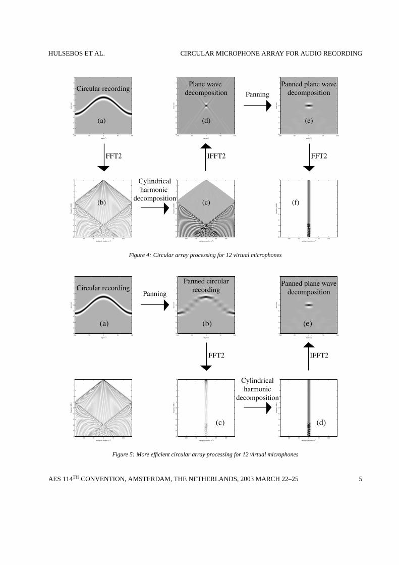
In figure 7 the angular fourier transforms of these windows areshown. All these windows contain approximately 24 nonzerofrequency components. This implies that at least 24 samplesin the angle (acquisition channels) are required for a sufficientaliasing-free wave field decomposition and virtual microphoneoutput creation, which is twice the amount of desired outputchannels. If only 12 acquisition channels were used, severeangular aliasing artifacts would occur in the wave decomposi-tion processing. Even with 24 samples the field is not entirelyfree from aliasing due to some frequency-lobing as can be seenfrom figure 7.
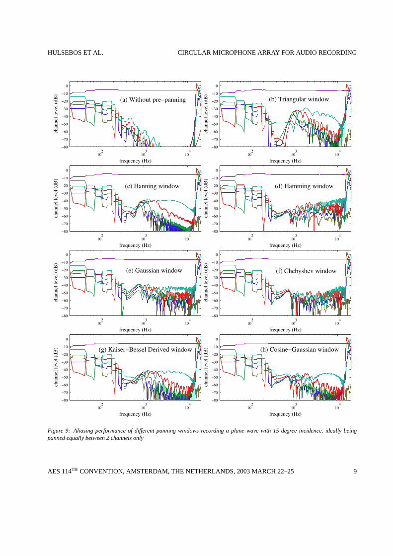
The effect of undersampling and frequency lobing describedabove can be easily demonstrated by processing a simulatedplane wave on the circular array using the processing schemefrom figure 5. The performance of the full 288 channel pro-cessing using the processing scheme from figure 4 is shown infigure 8(a) and 9(a) for angles of incidence of 0 and 15 degrees,respectively. This should be considered the best performancepossible with the given array size. Cross talk between the 12channels is extremely low, except for frequencies below 250
Hz, which, as discussed before, is due to the limited radius ofthe circular array The case of using the scheme from figure 5using 24 triangular angles shows a relatively poor performancein figure 8(b) and figure9(b). This is due to the fact that thetriangular window has quite strong side lobes in the frequencydomain which cause aliasing artifacts. In figure 8(c–g) and 9(c–g) 24 uniformly distributed Hanning, Hamming, Gaussian andthe product of a Gaussian and a cosine window are used, someof which are giving a much better performance due to smallerside lobes. Only the odd 12 output channels are shown in thesefigures since only those are used for a discrete 12 channel re-production system. See figure 10 for a sketch of the directiv-
030
60
90
120
150180
210
240
270
300
330
Figure 10: Virtual microphone directivity patterns
ity patterns of all 12 used virtual microphones. Note that theshapes are only valid between 150 and 15000 Hz and that theywill be distorted by aliasing caused by the frequency lobing.
AES 114TH CONVENTION, AMSTERDAM, THE NETHERLANDS, 2003 MARCH 22–25 6

HULSEBOS ET AL. CIRCULAR MICROPHONE ARRAY FOR AUDIO RECORDING
−60 −40 −20 0 20 40 60
0
0.2
0.4
0.6
0.8
1
angle (o)
(d) Chebyshev window−60 −40 −20 0 20 40 60
0
0.2
0.4
0.6
0.8
1
angle (o)
(c) Hamming window−60 −40 −20 0 20 40 60
0
0.2
0.4
0.6
0.8
1
angle (o)
(b) Hanning window−60 −40 −20 0 20 40 60
0
0.2
0.4
0.6
0.8
1
angle (o)
(a) Triangular window
−60 −40 −20 0 20 40 60−80
−70
−60
−50
−40
−30
−20
−10
0
multipole number (o−1)
Lev
el (
dB)
−60 −40 −20 0 20 40 60−80
−70
−60
−50
−40
−30
−20
−10
0
multipole number (o−1)
Lev
el (
dB)
−60 −40 −20 0 20 40 60−80
−70
−60
−50
−40
−30
−20
−10
0
multipole number (o−1)
Lev
el (
dB)
−60 −40 −20 0 20 40 60−80
−70
−60
−50
−40
−30
−20
−10
0
multipole number (o−1)
Lev
el (
dB)
Figure 7: Panning windows and their frequency responses
AES 114TH CONVENTION, AMSTERDAM, THE NETHERLANDS, 2003 MARCH 22–25 7
HULSEBOS ET AL. CIRCULAR MICROPHONE ARRAY FOR AUDIO RECORDING
102
103
104
−80
−70
−60
−50
−40
−30
−20
−10
0
frequency (Hz)
chan
nel l
evel
(dB
) (g) Kaiser−Bessel Derived window
102
103
104
−80
−70
−60
−50
−40
−30
−20
−10
0
frequency (Hz)
chan
nel l
evel
(dB
) (e) Gaussian window
102
103
104
−80
−70
−60
−50
−40
−30
−20
−10
0
frequency (Hz)
chan
nel l
evel
(dB
)
(c) Hanning window
102
103
104
−80
−70
−60
−50
−40
−30
−20
−10
0
frequency (Hz)
chan
nel l
evel
(dB
)
(a) Without pre−panning
102
103
104
−80
−70
−60
−50
−40
−30
−20
−10
0
frequency (Hz)
chan
nel l
evel
(dB
) (h) Cosine−Gaussian window
102
103
104
−80
−70
−60
−50
−40
−30
−20
−10
0
frequency (Hz)
chan
nel l
evel
(dB
) (f) Chebyshev window
102
103
104
−80
−70
−60
−50
−40
−30
−20
−10
0
frequency (Hz)
chan
nel l
evel
(dB
) (d) Hamming window
102
103
104
−80
−70
−60
−50
−40
−30
−20
−10
0
frequency (Hz)
chan
nel l
evel
(dB
) (b) Triangular window
Figure 8: Aliasing performance of different panning windows recording a plane wave with 0 degree incidence, ideally beingreproduced by 1 channel only
AES 114TH CONVENTION, AMSTERDAM, THE NETHERLANDS, 2003 MARCH 22–25 8
HULSEBOS ET AL. CIRCULAR MICROPHONE ARRAY FOR AUDIO RECORDING
102
103
104
−80
−70
−60
−50
−40
−30
−20
−10
0
frequency (Hz)
chan
nel l
evel
(dB
) (g) Kaiser−Bessel Derived window
102
103
104
−80
−70
−60
−50
−40
−30
−20
−10
0
frequency (Hz)
chan
nel l
evel
(dB
)
(e) Gaussian window
102
103
104
−80
−70
−60
−50
−40
−30
−20
−10
0
frequency (Hz)
chan
nel l
evel
(dB
)
(c) Hanning window
102
103
104
−80
−70
−60
−50
−40
−30
−20
−10
0
frequency (Hz)
chan
nel l
evel
(dB
)
(a) Without pre−panning
102
103
104
−80
−70
−60
−50
−40
−30
−20
−10
0
frequency (Hz)
chan
nel l
evel
(dB
) (h) Cosine−Gaussian window
102
103
104
−80
−70
−60
−50
−40
−30
−20
−10
0
frequency (Hz)
chan
nel l
evel
(dB
)
(f) Chebyshev window
102
103
104
−80
−70
−60
−50
−40
−30
−20
−10
0
frequency (Hz)
chan
nel l
evel
(dB
)
(d) Hamming window
102
103
104
−80
−70
−60
−50
−40
−30
−20
−10
0
frequency (Hz)
chan
nel l
evel
(dB
)
(b) Triangular window
Figure 9: Aliasing performance of different panning windows recording a plane wave with 15 degree incidence, ideally beingpanned equally between 2 channels only
AES 114TH CONVENTION, AMSTERDAM, THE NETHERLANDS, 2003 MARCH 22–25 9

HULSEBOS ET AL. CIRCULAR MICROPHONE ARRAY FOR AUDIO RECORDING
Using all 24 output channels directly for a discrete 24 channelreproduction system is probably not a good idea, since the evenchannels have a strong overlap in angle with the odd ones im-plying unnecessary crosstalk between them that results in combfilter effects between the channels during reproduction. How-ever, as will be shown later, it is possible to create 24 bettervirtual microphones with less crosstalk from the original onesusing an output matrix.
REAL-TIME WAVE DECOMPOSITION PROCESSING
Until now only examples where shown using simple, shortand easy to process wave fields, like a simulated Dirac planewave recording. In practice it is necessary to decompose acontinuous stream of 24 channels of audio in real time. Thiscan be done by splitting the audio input stream into timeblocks, applying a FFT2-based convolution filter in thekθ , ω-domain, transforming the data back toθ, ω-domain and usingthe overlap-add approach to combine the blocks into an outputaudio stream. This type of processing is certainly feasible inreal time on a single pc nowadays. The FFT2-based convolu-tion filter can be designed to account for both wave decomposi-tion and compensation for the non-ideal actual performance ofthe cardioid microphones in terms of frequency response andfrequency dependent directivity pattern.
OUTPUT MATRIX
Having a discrete 12 channel microphone array is nice, how-ever it will not always be flexible and desirable to use the 12fixed virtual microphones from figure 10 directly. This wouldimply a different array design for each different reproductionsystem. For example, the 12 discrete output channels on itselfcannot be used directly for a 5.1 or 7.1 reproduction. However,by choosing the 24 panned acquisition channels one is not lim-ited to the 12 virtual microphones from figure 10 but can infact use any linear combination of all 24 virtual microphonesto create new virtual microphones. This can be implementedby using a simple output matrix. The 24 original channels arerouted through a matrix to obtain any desired number of outputchannels. Suppose thati1 . . . i24 are the panned and decom-posed output channels of the array and thus the input channelsfor the matrix and supposeo1 . . . oN are theN desired outputchannels. Then one can write o1
...
oN
=
M1,1 M1,2 · · · M1,24M2,1 M2,2 · · · M2,24
.... . .
. . ....
MN,1 MN,2 · · · MN,24
i1
...
i24
(5)
The coefficientsMn,m of the matrix determine the directivitypatterns for the N virtual microphones. In this case a frequencyindependent virtual microphone is considered. If one wants tocreate a frequency dependent directivity pattern, the output ma-trix coefficients should be functions of the temporal frequency
ω instead of being constants. As a first trivial example for anoutput matrix one could consider the full 12 channel discreteoutput system. The matix for this example is shown as a col-ormap in figure 11 . In this case the matrix is very simple: only
�1
�0.5
0
0.5
1
Figure 11: Matrix for 12 channel output
the 12 odd input channels are used and sent directly to the 12outputs.
Suppose now as a second, more interesting example 5 discretevirtual microphones compatible with 5.1 reproduction anglesand covering the full 360 degrees angle. If smooth transitionbetween the left, right and surround channels is desired, thematrix could look like figure 12. This matrix was obtained
�1
0
1
Figure 12: Matrix for 5.1 output using gradual panning be-tween all 5 channels
0.5
1030
60
90
120
150180
210
240
270
300
330
Figure 13: Desired and actual virtual microphone directivitypatterns for 5.1 output using gradual panning between all 5channels. The black lines are the desired patterns and the solidcolors are the actual patterns
by creating a band-limited (24 samples long) inversion filterfor the used Hanning pre-panning window from figure 7(b) in
AES 114TH CONVENTION, AMSTERDAM, THE NETHERLANDS, 2003 MARCH 22–25 10

HULSEBOS ET AL. CIRCULAR MICROPHONE ARRAY FOR AUDIO RECORDING
the angular frequency domain and convolving this with the 24sample band-limited version of the desired 5.1 directivity pat-terns, using multiplication in the angular Fourier domain. Thedirectivity patterns for the desired and actually created virtualmicrophones resulting from this matrix are shown in figure 13
If one desires a much sharper transition between the channelsresulting in less overlap and correlation between the front andthe rear channels, the matrix from figure 14 can be used. The
�1
0
1
Figure 14: Matrix for 5.1 output using sharp transition betweenfront and rear channels
0.5
1030
60
90
120
150180
210
240
270
300
330
Figure 15: Desired and actual virtual microphone directivitypatterns for 5.1 output using sharp transition between front andrear channels. The black lines are the desired patterns and thesolid colors are the actual patterns.
directivity patterns of the resulting virtual microphones in thisare shown in figure 15. Notice that the obtained virtual micro-phones are not perfectly equal to the desired ones, since thedesired ones contain a small amount of high frequency compo-nents that cannot be resolved.
These were only a few simple examples. Notice that any di-rectivity pattern can be created in this way as long as it is notsharper than the directivity patterns of the original 24 micro-phone output channels. Clearly it is not possible to achievereally sharper directivity patterns, since for that purpose higherorder cylindrical harmonics, that have been filtered out by thepanning step in figure 5 are required. It is possible however tocreate slightly more directive beams. For example, the matrixfrom figure16 delivers 24 discrete audio channels, but at the
price of more sidelobes (crosstalk) and more noise sensitivity.Their directivity patterns are shown in figure 17
�2
�1.5
�1
�0.5
0
0.5
1
1.5
2
Figure 16: Matrix for 24 discrete output channels
0.5
030
60
90
120
150180
210
240
270
300
330
Figure 17: Desired and actual virtual microphone directivitypatterns 24 discrete output channels.
The output matrix can be generalized even further by usingcomplex matrix coefficients instead of only real ones. A com-plex coefficient implies, apart from the amplitude gain and sign,also a phase rotation in the audio signal. This could partic-ularly be useful as a decorrelation/diffusion filter for the sur-round channels in the previous 5.1 examples, in case they areonly used for the recording of ambiance (for example room ef-fect and applause).
The matrixing is a process that can be applied and optimizedto the taste of the sound engineer afterwards, if during the liverecording the full 24 channels were stored. This approach iscomparable B-format recording, in which case the 4 B-formatsignals can also be combined (matrixed) into the final outputsafterwards by using a B-format processor [5].
AES 114TH CONVENTION, AMSTERDAM, THE NETHERLANDS, 2003 MARCH 22–25 11

HULSEBOS ET AL. CIRCULAR MICROPHONE ARRAY FOR AUDIO RECORDING
30 degrees 60 degrees 75 degrees exactly 90 degrees
Figure 18: Frequency response of the 12 discrete channels for different elevation angles
ELEVATION ANGLES
Elevated sources cannot be expected to be properly imaged by acircular array. A spherical array, being quite unfeasible in prac-tice currently, should ideally be used for that purpose. The useof such an array can however only be justified if the reproduc-tion system is also capable of reproduction elevated sources,which is nog the case for most reproduction systems, includ-ing WFS. It will be shown that although the recording perfor-mance for elevated sources is not ideal, this should not be amajor problem in practice. In figure 18 the content of the 12output channels of a plane Dirac wave with various elevationangles simulated on the array system is shown. As can be con-cluded from this figure, an elevated source will have contribu-tions from two angles, namely the angle of the real source andthe opposite angle. An elevated source in the front will thusbe reproduced as a source in front and a source in the back.Furthermore, as can also be seen from figure 18, the angularresolution for an elevated source is more limited, which affectsthe low temporal frequencies. The energy ratio between frontand back is determined by the elevation angle. For extreme ele-vation angles within 1-2 degrees from the vertical axis, all out-put channels at all angles are affected and quite a strong highfrequency amplification occurs. However, since this is only avery small fraction of the full 4π space angle where normallyno direct sound sources or early reflection mirror images arepresent, it can be expected not to have a strong effect on theoverall array performance in real-life recording situations.
NOISE PERFORMANCE OF A CIRCULAR ARRAY
Next noise sensitivity and the effect of variations between in-
dividual microphone capsules on the overall array performanceare investigated. In figure 19 the noise spectrum of an individ-ual cardioid microphone is shown. The microphones used pro-duce a pink noise signal. The total theoretical noise spectrumfor the array including processing and 12 channel reproductionat the sweet spot is shown in figure 19. The noise level is cal-ibrated using a 1 kHz plane wave in such a way that the soundpressure level of the wave in the center of the microphone arrayis equal to the sound pressure level of reproduced 1 kHz toneat the sweet spot of the 12 channel reproduction system. Fig-ure 19 shows that the spectrum of the noise after the processinghas become white. The signal to noise ratio for the whole arraysystem improves drastically for low frequencies compared tothe single microphone performance, however, for frequenciesabove 3 kHz the noise performance deteriorates. This results inan overall noise level increase of 1–2dB(A).
Variations between individual microphone capsules, which willmainly be level variations caused by the build in microphonepre-amplifiers and weighting resistors, were also simulated.Fluctuations of 1–2 dB in microphone sensitivities were as-sumed. Although, as expected, the actual cross talk separa-tion between the 12 channels becomes a bit worse in the caseof these variations, the overall array performance of the arrayis not too sensitive to such variations and 1–2 dB variation isacceptable.
BUILDING A PROTOTYPE ARRAY
Currently a prototype circular array is being build. The arrayconsists of 4 parts of pre-bended aluminium strips that can bejointed together easily to form a circle. Holes are drilled in the
AES 114TH CONVENTION, AMSTERDAM, THE NETHERLANDS, 2003 MARCH 22–25 12

HULSEBOS ET AL. CIRCULAR MICROPHONE ARRAY FOR AUDIO RECORDING
102
103
104
30
40
50
60
70
80
90
frequency (Hz)
Individual microphone noiseArray output noise
Figure 19: Noise levels from a single microphone and the complete array system
strips in which the microphone capsules are mounted. At thebackside of the strips shielded multi-layer print boards are at-tached that contain connections to the microphones, 4× 288weighting resistors, 24 preamplifiers and some other requiredelectronic components. The boards are constructed as thin aspossible and have large holes at the positions of the micro-phones to avoid acoustic shielding at the backside of the car-dioids as much as possible.The microphone capsules used aretype EM-135 from Primomic. These relatively cheap micro-phones should not be expected to deliver hi-end studio qualityin terms of noise and high frequency performance. However,the spatial quality of the system should be convincing enoughto demonstrate the advantages of the proposed circular micro-phone array technology. The development and design of a mi-crophone array using only 24 microphone capsules which aremore extended in space is currently not taking place but couldbe a very interesting and relatively cheap high performance so-lution for the future.
CONCLUSIONS
In this paper a circular array has been proposed that can de-liver discrete multichannel audio by simulation virtual micro-phones in post processing with well controlled and sharp direc-tivity patterns that cannot be achieved with conventional mi-crophone technology. Although such an array requires a largenumber of microphone capsules to avoid spatial aliasing, thenumber of recording channels doesn’t have to be large at allsince part of the processing can already be done in the analog
domain using simple resistor ladder networks. Furthermore, ifwell shaped, in space extended microphones could be designed,such ladder networks would become unnecessary and aliasingcould be completely avoided. By using a complex output ma-trix almost any desired virtual microphone set can be createdand auditioned in real time from the original recorded micro-phone output channels. Since the array under consideration iscircular and not spherical, elevation angles cannot be recordedand reproduced properly. In practical applications however thisshould not cause a big problem, even in case of strong ceilingreflections. The array system also is not very sensitive to noiseand fluctuations in the microphone capsules and weighting re-sistors. A prototype circular array is currently being build.
REFERENCES
[1] E. Hulsebos, D. de Vries and Emmanuelle BourdillatIm-proved microphone array configurations for auralizationof sound fields by Wave Field Synthesis, preprint 5337 of110th AES Convention, Amsterdam, Netherlands (2001)
[2] E. Hulsebos, D. de Vries and Emmanuelle BourdillatIm-proved microphone array configurations for auralizationof sound fields by Wave Field Synthesis, J. Audio Eng.Soc., Volume 50, number 10, pp. 779-790, New York,USA (2002)
[3] E. Hulsebos and D. de Vries,Parameterization and repro-duction of concert hall acoustics measured with a circularmicrophone array, preprint 5579 of 112th AES Conven-tion, Munich, Germany (2002)
AES 114TH CONVENTION, AMSTERDAM, THE NETHERLANDS, 2003 MARCH 22–25 13
HULSEBOS ET AL. CIRCULAR MICROPHONE ARRAY FOR AUDIO RECORDING
[4] M. Abramowitz and I. A. Stegun,Handbook of mathe-matic functions, Dover Publications, New York, UnitedStates (1965)
[5] K. Farrar,Soundfield microphone, Wireless world, octo-ber edition pp. 48–50 (1979)
AES 114TH CONVENTION, AMSTERDAM, THE NETHERLANDS, 2003 MARCH 22–25 14