Circular e + e - Colliders
46
Circular e + e - Colliders John Seeman SLAC Snowmass: Lepton Colliders April 10, 2013
-
Upload
mona-deleon -
Category
Documents
-
view
31 -
download
0
description
Circular e + e - Colliders. John Seeman SLAC Snowmass: Lepton Colliders April 10, 2013. Collider Topics. Brief: Existing e+e - colliders DAFNE BEPC-II VEPP-4 VEPP-2000 Brief: Proposed low energy colliders Charm Tau at Cabibbo-Lab, Tor Vergata, Italy - PowerPoint PPT Presentation
Transcript of Circular e + e - Colliders
Circular e+e- Colliders
John Seeman
SLAC
Snowmass: Lepton Colliders
April 10, 2013

2
Collider Topics
Brief: Existing e+e- colliders
DAFNE
BEPC-II
VEPP-4
VEPP-2000
Brief: Proposed low energy colliders
Charm Tau at Cabibbo-Lab, Tor Vergata, Italy
Charm Tau in Novosibirsk,
Medium energy e+e- collider under construction
SuperKEKB
Potential new high energy colliders
LHeC
Circular Z
Circular Higgs
Circular Top
R&D on technologies and beam dynamics
Potential US Roles
3
Thanks for inputs:
M. Biagini, A. Blondel, A. Bogomyagkov, A. Butterworth, Y.
Cai, J. Fox, Y. Funakoshi, M. Giorgi, E. Jensen, M. Kikuchi,
E. Levichev, K. Ohmi, K. Oide, P. Piminov, P. Raimondi, M.
Ross, M. Sato, D. Schulte, D. Shatilov, D. Shwartz, Y.
Suetsugu, M. Sullivan, T. Suwada, S. Tomassini, U.
Wienands, M. Zanetti, Y. Zhang, F. Zimmermann, M. Zobov
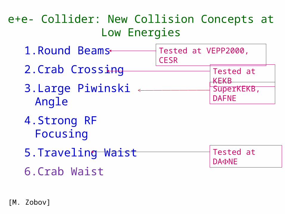
e+e- Collider: New Collision Concepts at Low Energies
1.Round Beams
2.Crab Crossing
3.Large Piwinski Angle
4.Strong RF Focusing
5.Traveling Waist
6.Crab Waist
Tested at VEPP2000, CESR
Tested at KEKB
Tested at DAFNE
[M. Zobov]
SuperKEKB, DAFNE
5
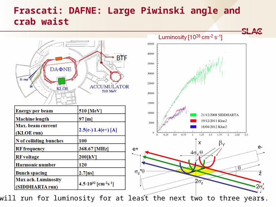
Frascati: DAFNE: Large Piwinski angle and crab waist
DAFNE will run for luminosity for at least the next two to three years.
6
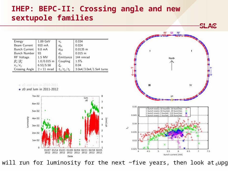
IHEP: BEPC-II: Crossing angle and new sextupole families
BEPC-II will run for luminosity for the next ~five years, then look at upgrades.
7
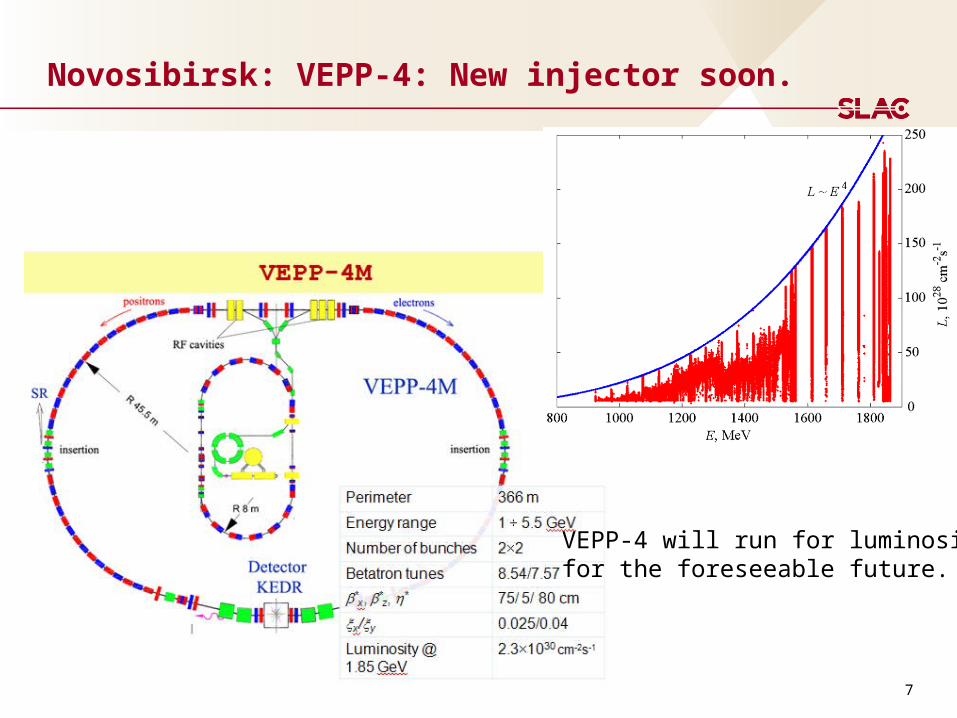
Novosibirsk: VEPP-4: New injector soon.
VEPP-4 will run for luminosityfor the foreseeable future.
8
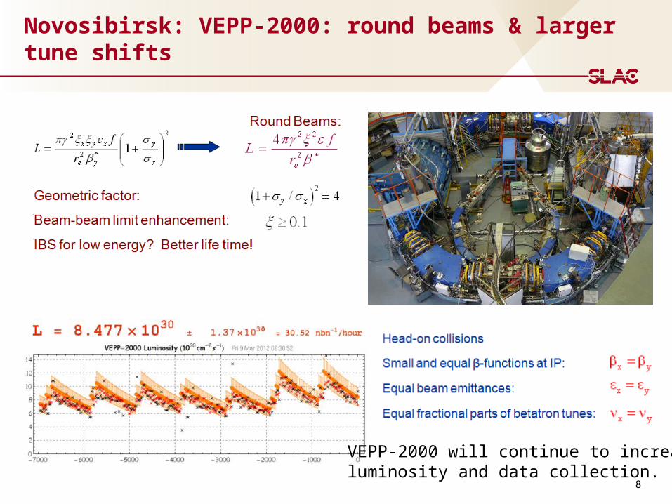
Novosibirsk: VEPP-2000: round beams & larger tune shifts
VEPP-2000 will continue to increaseluminosity and data collection.
9
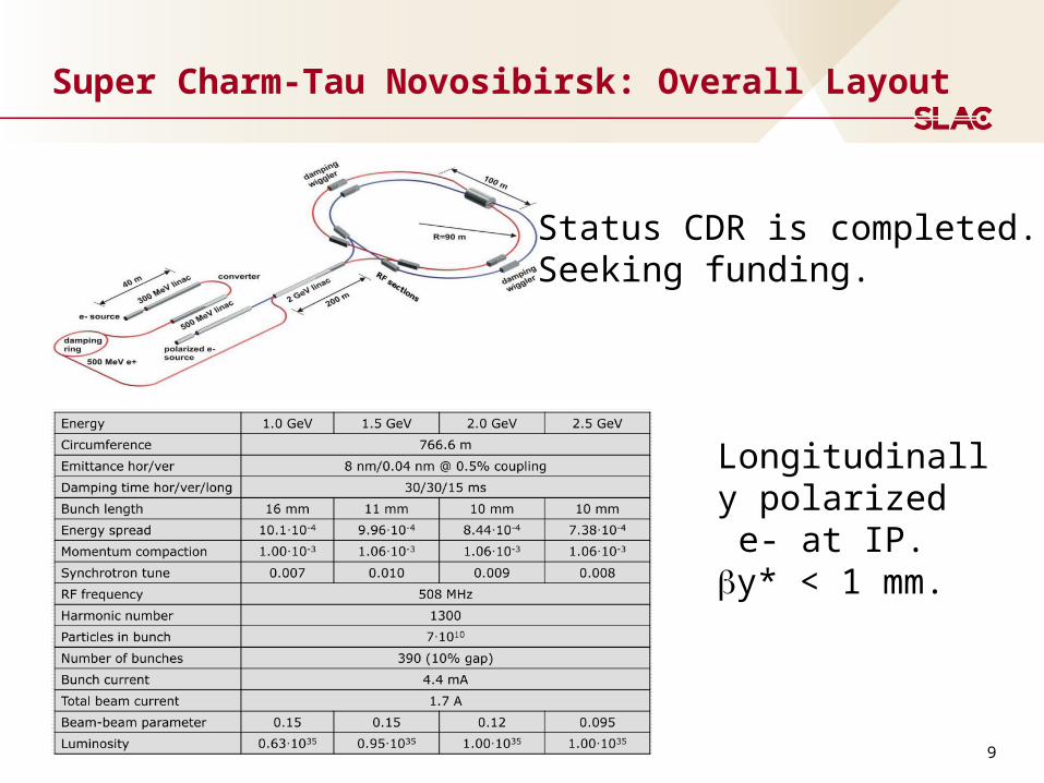
Super Charm-Tau Novosibirsk: Overall Layout
Status CDR is completed. Seeking funding.
Longitudinally polarized e- at IP.by* < 1 mm.
10
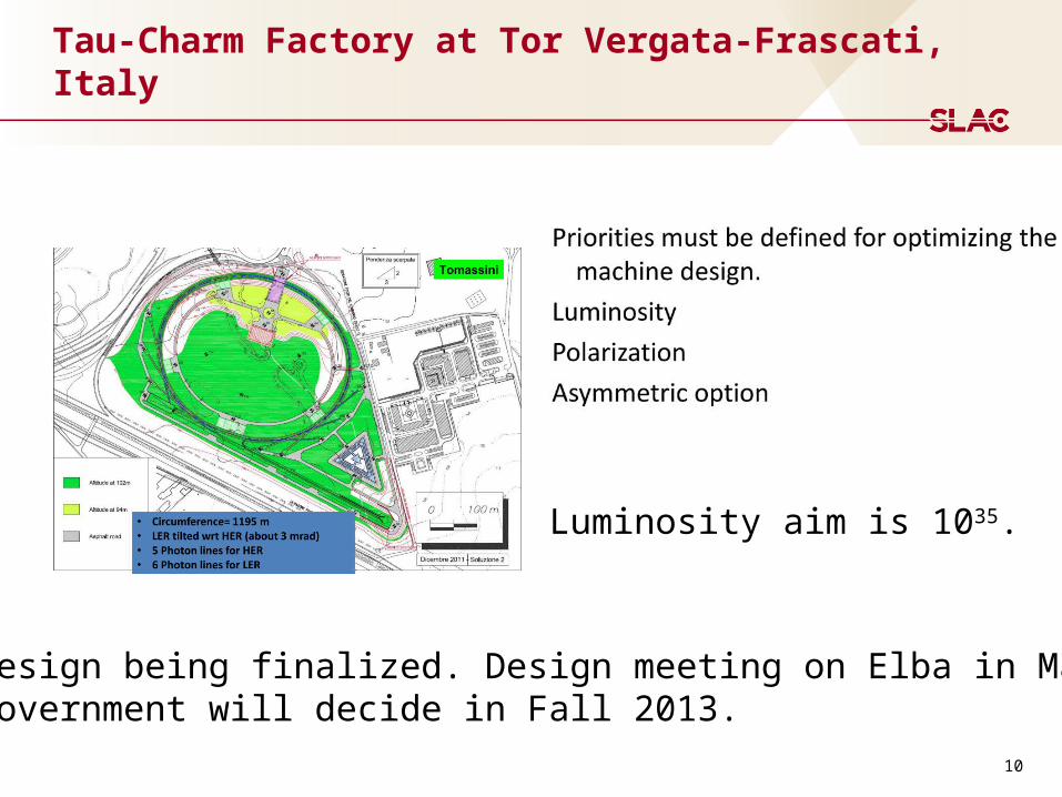
Tau-Charm Factory at Tor Vergata-Frascati, Italy
Design being finalized. Design meeting on Elba in May. Government will decide in Fall 2013.
Luminosity aim is 1035.
11
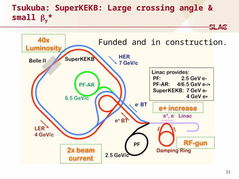
Tsukuba: SuperKEKB: Large crossing angle & small by*
Funded and in construction.
12
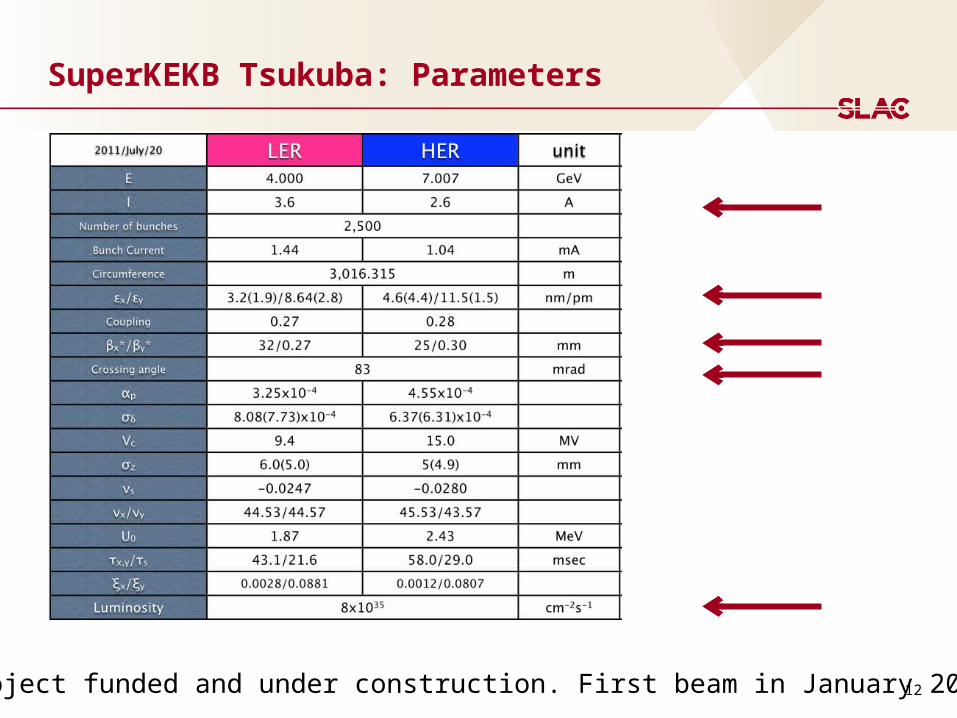
SuperKEKB Tsukuba: Parameters
Project funded and under construction. First beam in January 2015.
13
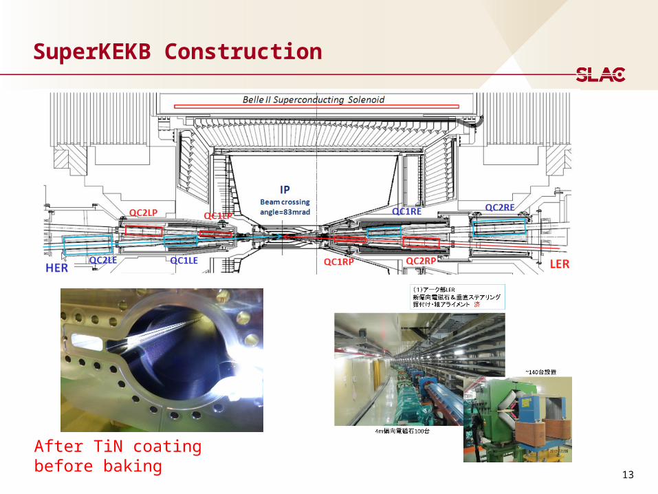
SuperKEKB Construction
After TiN coatingbefore baking

14
Key Facility Features for these e+e- Colliders
Two rings with a single interaction point
Crossing angle at the IP with very flat beams (emittance ratio = ~300)
Need low detector backgrounds
Crab waist collisions
Wigglers to reduce damping times and emittances
Picometer-vertical and nanometer-horizontal emittances
Longitudinal polarized e- beams at the IP with spin rotators
Low emittance beam with beam-beam effects
Polarized beam with strong beam-beam effects
High currents:
Coherent Synchrotron Radiation (CSR)
Electron Cloud Instability ECI
Fast Ion Instability FII
Low impedance vacuum chambers
High power vacuum chambers
15
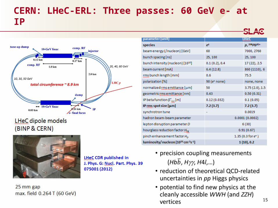
CERN: LHeC-ERL: Three passes: 60 GeV e- at IP
16
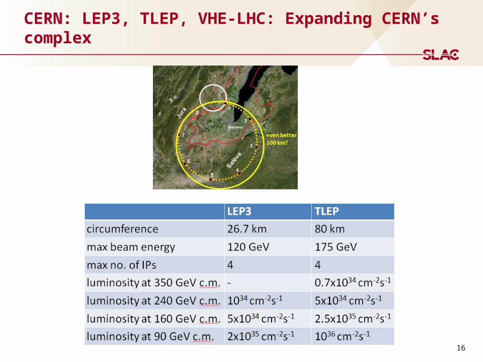
CERN: LEP3, TLEP, VHE-LHC: Expanding CERN’s complex
17
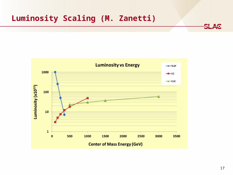
Luminosity Scaling (M. Zanetti)
18
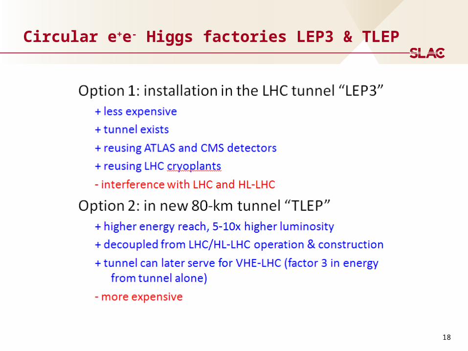
Circular e+e- Higgs factories LEP3 & TLEP
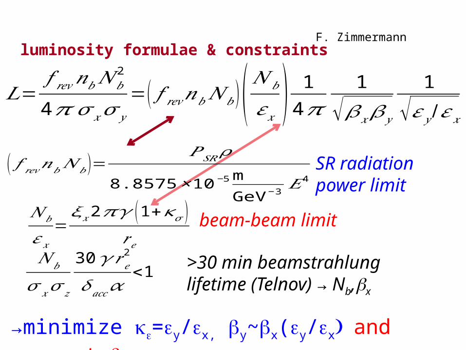
luminosity formulae & constraints
𝐿=𝑓 𝑟𝑒𝑣𝑛𝑏𝑁 𝑏
2
4𝜋 𝜎𝑥𝜎 𝑦
=( 𝑓 𝑟𝑒𝑣𝑛𝑏𝑁 𝑏)(𝑁 𝑏
𝜀𝑥) 14𝜋 1
√𝛽𝑥 𝛽𝑦
1
√𝜀𝑦 /𝜀𝑥
𝑁𝑏
𝜀𝑥=𝜉 𝑥2𝜋𝛾 (1+𝜅𝜎 )
𝑟 𝑒
( 𝑓 𝑟𝑒𝑣𝑛𝑏𝑁 𝑏)=𝑃𝑆𝑅𝜌
8.8575×10⁻⁵mGeV−3
𝐸4
𝑁 𝑏
𝜎 𝑥𝜎𝑧
30𝛾𝑟𝑒2
𝛿𝑎𝑐𝑐𝛼<1
SR radiation power limit
beam-beam limit
>30 min beamstrahlung lifetime (Telnov) → Nb,bx
→minimize ke=ey/ex, by~bx(ey/ex) and respect by≈sz
F. Zimmermann
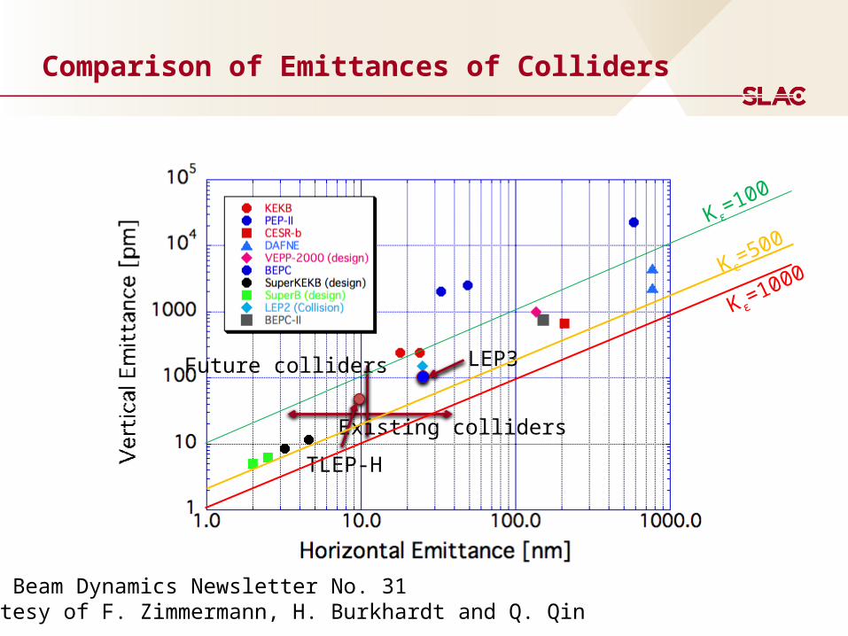
Comparison of Emittances of Colliders
Existing colliders
Future colliders
From Beam Dynamics Newsletter No. 31Courtesy of F. Zimmermann, H. Burkhardt and Q. Qin
LEP3
TLEP-H
Κ ε=100
Κ ε=500
Κ ε=1000
21
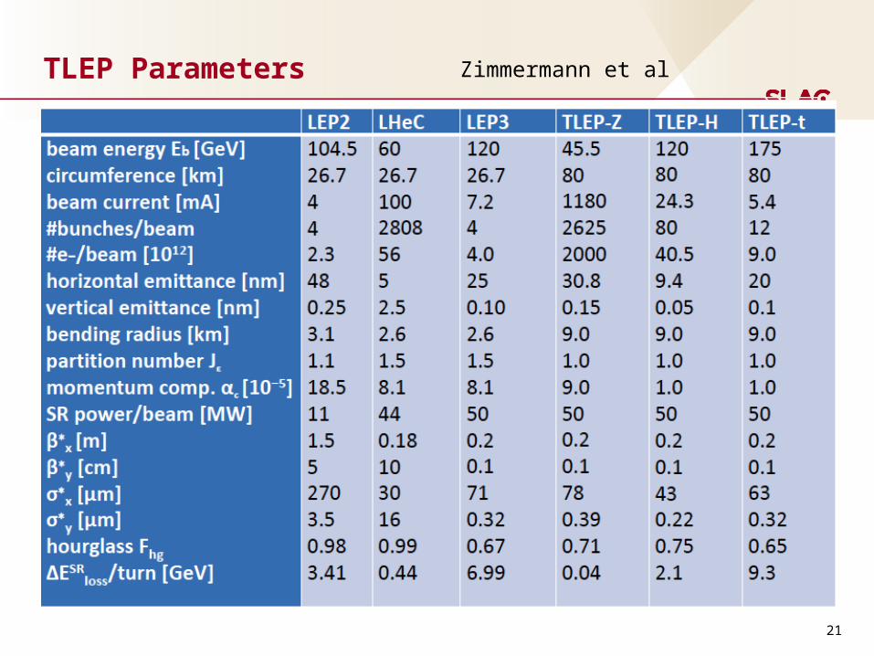
TLEP Parameters
Zimmermann et al
22
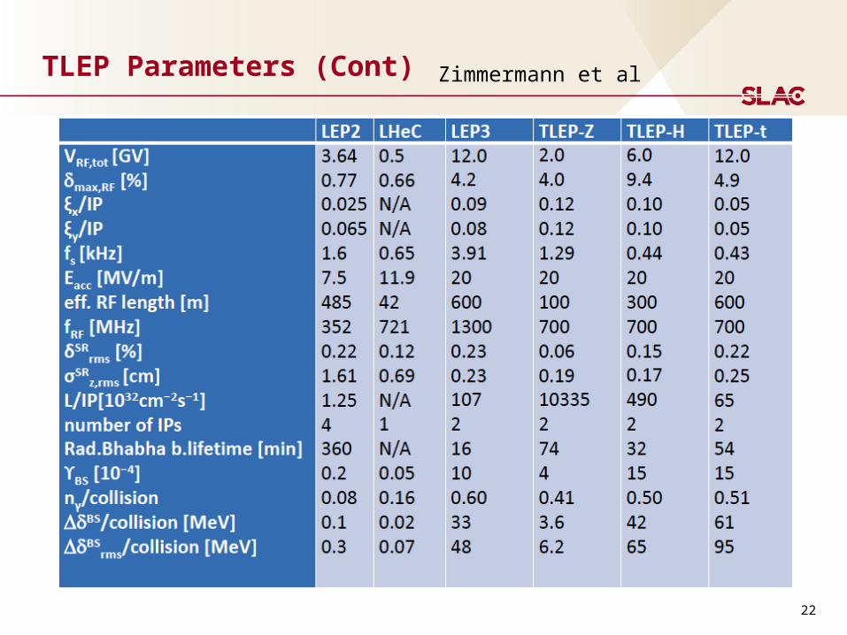
TLEP Parameters (Cont) Zimmermann et al
23
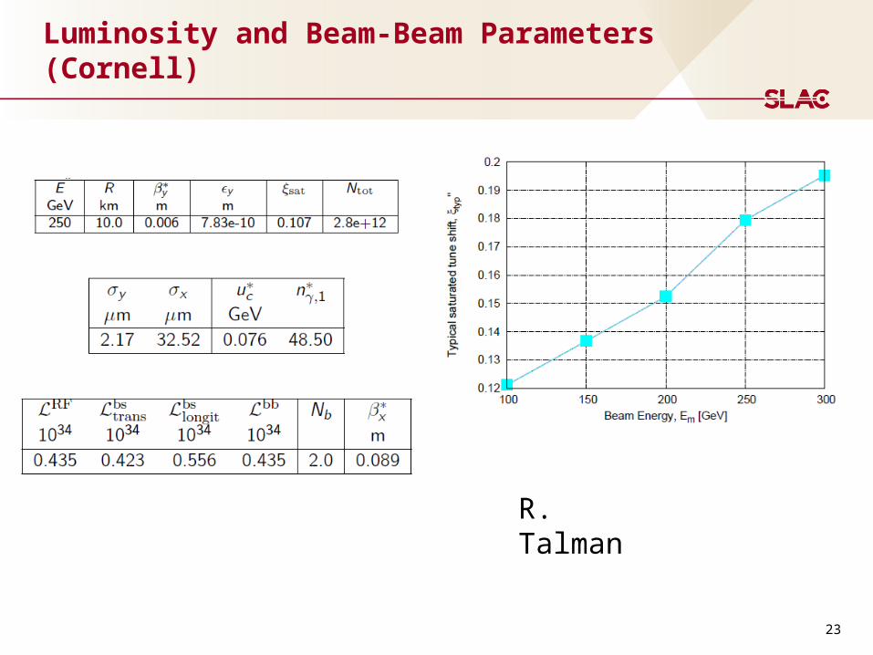
Luminosity and Beam-Beam Parameters (Cornell)
R. Talman

Vertical rms IP spot sizes in nm
LEP2 3500
KEKB 940SLC 500 LEP3 320 TLEP-H 220ATF2, FFTB 73 (35), 77SuperKEKB 50ILC 5 – 8CLIC 1 – 2
LEP3/TLEPwill learn from ATF2 &SuperKEKB
by*:
5 cm→1 mm
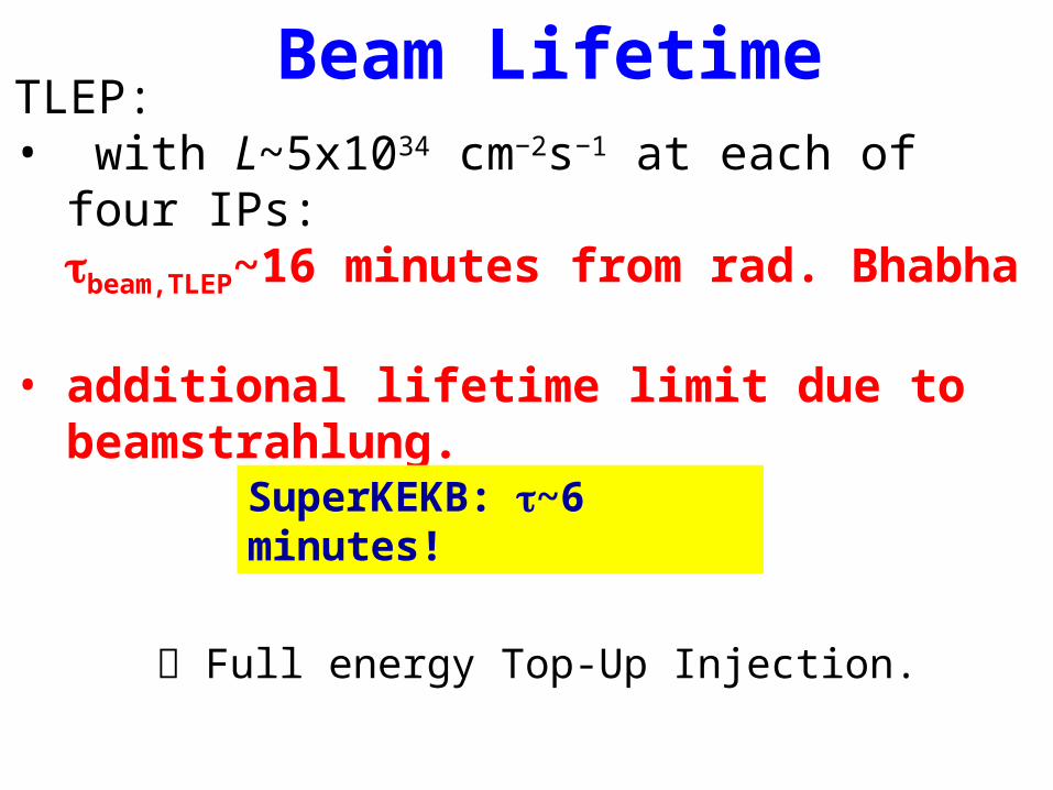
TLEP:• with L~5x1034 cm−2s−1 at each of four IPs:
tbeam,TLEP~16 minutes from rad. Bhabha • additional lifetime limit due to
beamstrahlung.
Beam Lifetime
SuperKEKB: t~6 minutes!
Full energy Top-Up Injection.

RF: Top-up injector ring
VRF ≥ 9.7 GV
• (only for quantum lifetime)
SR power very small
• (beam current ~ 1% of collider ring)
Average cryogenic heat load very small
• (duty cycle < 10%)
Power is dominated by ramp acceleration:
• for a 1.6 second ramp length:
TLEP-t
Beam current [mA] 0.054
Energy swing [GeV] 155
Max. SR power/cavity [kW] 6.2
Acceleration power [kW] 18
Max. power per cavity [kW]
24
Well within the 200 kW budget
Butterworth,Jensen
9.00 10 9 9.50 10 9 1.00 10 10 1.05 10 10 1.10 10 10 1.15 10 10 1.20 10 100
1
2
3
4
5
6
VRF V
max,RF
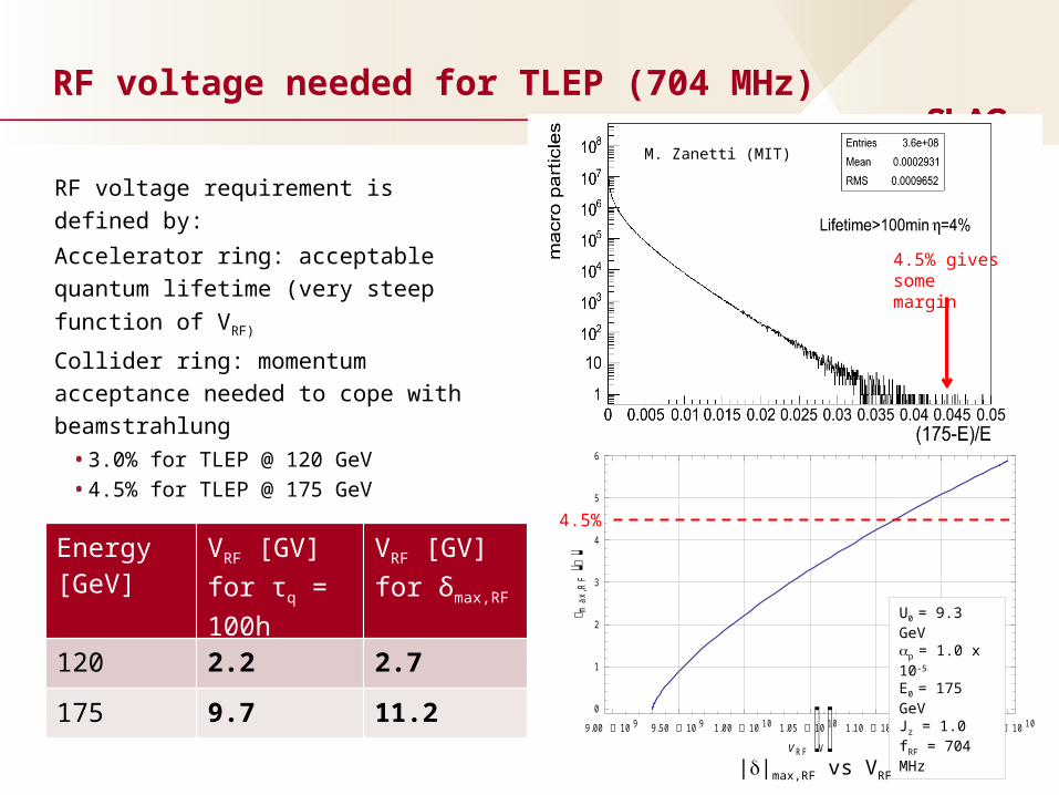
RF voltage requirement is defined by:
Accelerator ring: acceptable quantum
lifetime (very steep function of VRF)
Collider ring: momentum acceptance
needed to cope with beamstrahlung
• 3.0% for TLEP @ 120 GeV
• 4.5% for TLEP @ 175 GeV
RF voltage needed for TLEP (704 MHz)
U0 = 9.3 GeVp = 1.0 x 10⁻⁵
E0 = 175 GeVJz = 1.0fRF = 704 MHz
Energy [GeV]
VRF [GV]for τq = 100h
VRF [GV]for δmax,RF
120 2.2 2.7
175 9.7 11.2
||max,RF vs VRF
M. Zanetti (MIT)
4.5% gives some margin
4.5%
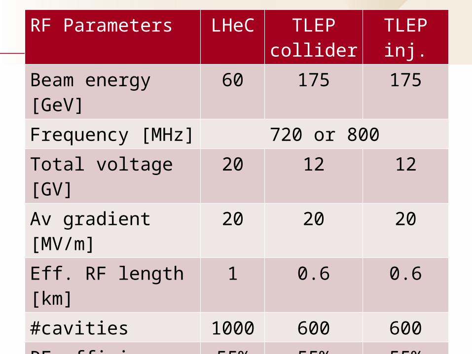
RF Parameters LHeC TLEP collider
TLEP inj.
Beam energy [GeV] 60 175 175Frequency [MHz] 720 or 800Total voltage [GV] 20 12 12Av gradient [MV/m] 20 20 20Eff. RF length [km] 1 0.6 0.6#cavities 1000 600 600RF efficiency (wall→beam)
55% 55% 55%
Power throughput [MW]
17 110 10 (peak)
Power / cavity [kW] 17 183 17
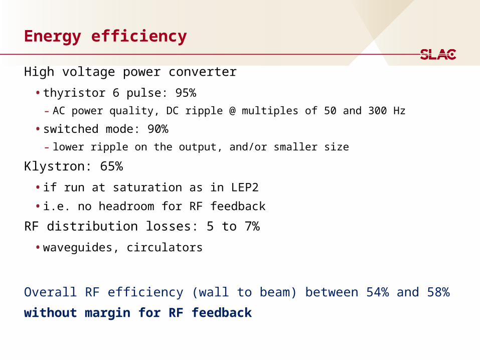
Energy efficiency
High voltage power converter
• thyristor 6 pulse: 95%- AC power quality, DC ripple @ multiples of 50 and 300 Hz
• switched mode: 90%- lower ripple on the output, and/or smaller size
Klystron: 65%
• if run at saturation as in LEP2
• i.e. no headroom for RF feedback
RF distribution losses: 5 to 7%
• waveguides, circulators
Overall RF efficiency (wall to beam) between 54% and 58%
without margin for RF feedback
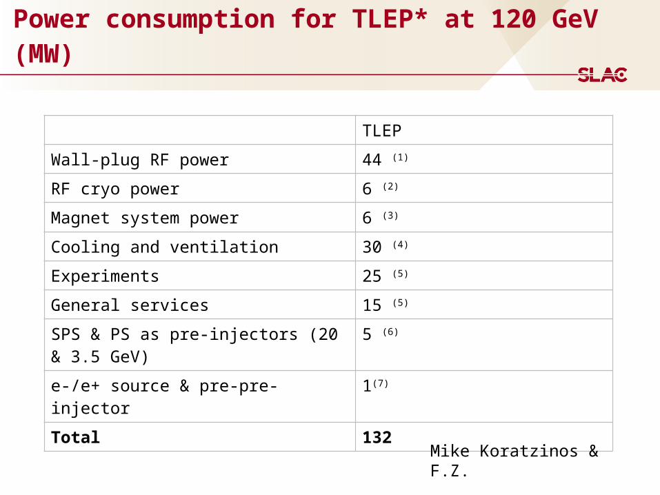
Power consumption for TLEP* at 120 GeV (MW)
TLEP
Wall-plug RF power 44 (1)
RF cryo power 6 (2)
Magnet system power 6 (3)
Cooling and ventilation 30 (4)
Experiments 25 (5)
General services 15 (5)
SPS & PS as pre-injectors (20 & 3.5 GeV)
5 (6)
e-/e+ source & pre-pre-injector 1(7)
Total 132
Mike Koratzinos & F.Z.
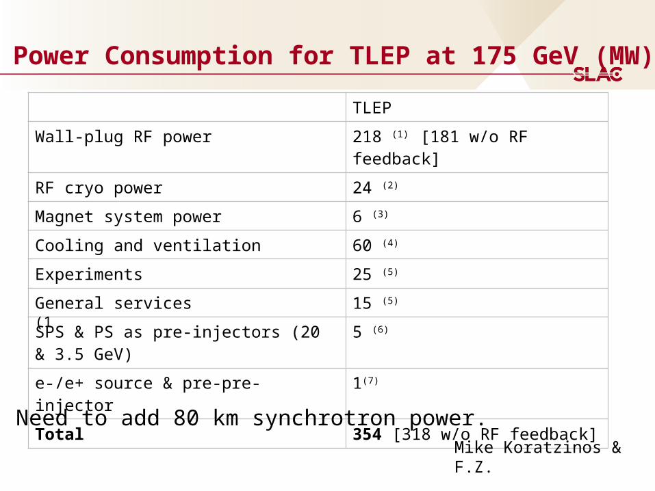
Power Consumption for TLEP at 175 GeV (MW)
TLEP
Wall-plug RF power 218 (1) [181 w/o RF feedback]
RF cryo power 24 (2)
Magnet system power 6 (3)
Cooling and ventilation 60 (4)
Experiments 25 (5)
General services 15 (5)
SPS & PS as pre-injectors (20 & 3.5 GeV)
5 (6)
e-/e+ source & pre-pre-injector 1(7)
Total 354 [318 w/o RF feedback]
(1
Mike Koratzinos & F.Z.
Need to add 80 km synchrotron power.
RF System Overall
An RF system based on 700 MHz SC cavity technology such
as being developed for eRHIC, SPS, ESS seems to be a good
choice.
• ongoing R&D at BNL, CERN, ESS for 704 MHz cavities and
components
• RF wall-plug to beam efficiency around 54 – 58% (w/o cryo)
• total power consumption for 175 GeV around 220 MW including
cryogenics, resulting in efficiency around 48 – 51%.
Open questions and R&D necessary
• fundamental power couplers: R&D ongoing
• HOM damping scheme: study needed
• low level RF & feedback requirements: study needed
• construction cost?
Butterworth, Jensen
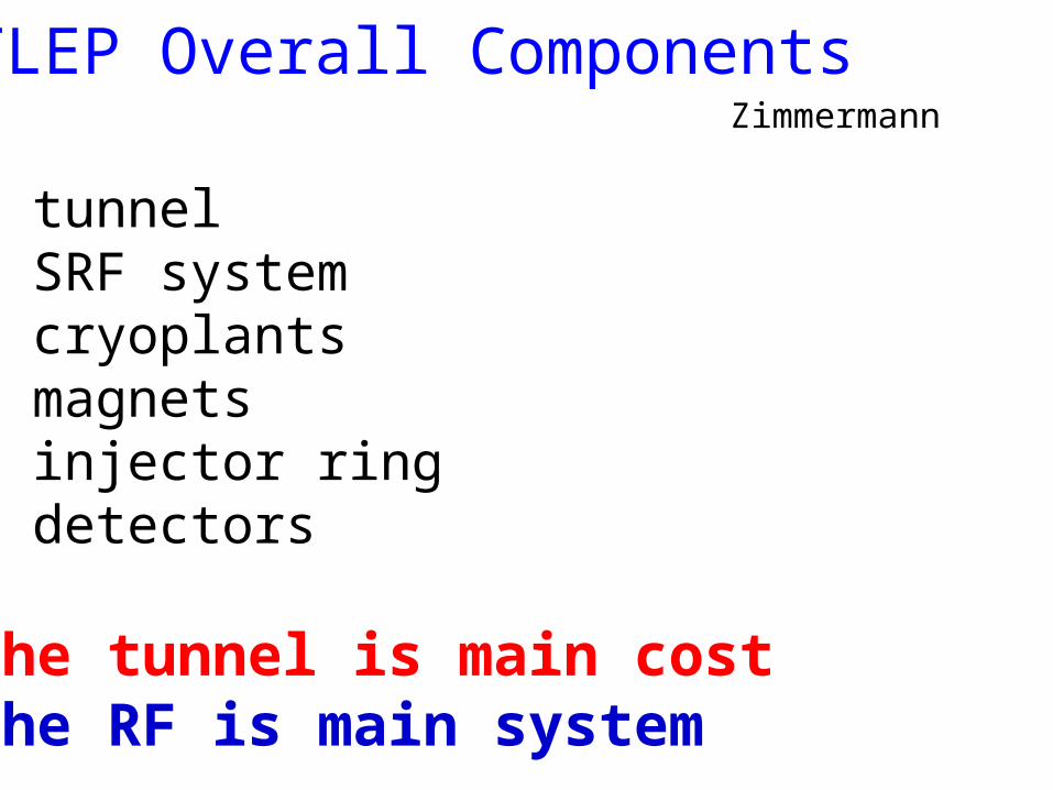
TLEP Overall Components
tunnel SRF system cryoplants magnets injector ring detectors
The tunnel is main costThe RF is main system
Zimmermann

34
Tunnel costs: 80 km
Zimmermann
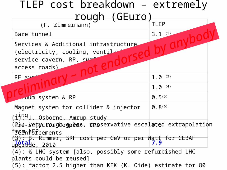
TLEP cost breakdown – extremely rough (GEuro)TLEP
Bare tunnel 3.1 (1)
Services & Additional infrastructure (electricity, cooling, ventilation, service cavern, RP, surface structure, access roads)
1.0(2)
RF system 1.0 (3)
Cryo system 1.0 (4)
Vacuum system & RP 0.5(5)
Magnet system for collider & injector ring 0.8(6)
Pre-injector complex SPS reinforcements 0.5
Total 7.9
(1): J. Osborne, Amrup study(2): very rough guess, conservative escalated extrapolation from LEP(3): B. Rimmer, SRF cost per GeV or per Watt for CEBAF upgrade, 2010(4): ½ LHC system [also, possibly some refurbished LHC plants could be reused](5): factor 2.5 higher than KEK (K. Oide) estimate for 80 km ring(6): 24,000 magnets for collider & injector; cost per magnet 30 kCHF (LHeC); 10% added; no cost saving from mass production assumedNote: detector costs not included
preliminary – not endorsed by anybody(F. Zimmermann)
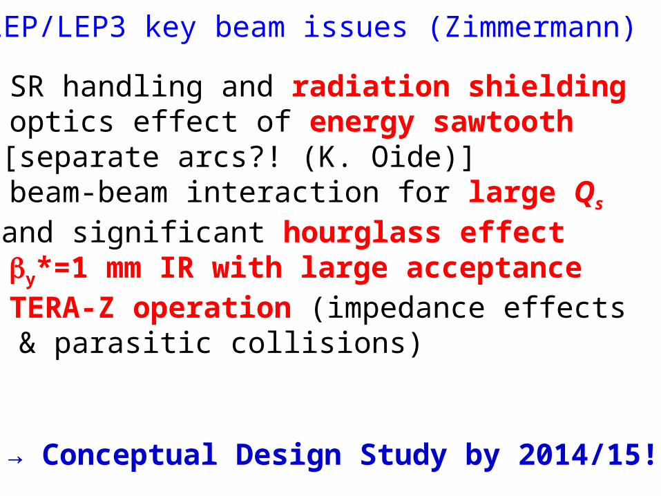
TLEP/LEP3 key beam issues (Zimmermann)
SR handling and radiation shielding optics effect of energy sawtooth
[separate arcs?! (K. Oide)] beam-beam interaction for large Qs
and significant hourglass effect by*=1 mm IR with large acceptance TERA-Z operation (impedance effects
& parasitic collisions)
→ Conceptual Design Study by 2014/15!

1980 1990 2000 2010 2020 2030
LHC Constr. PhysicsProto.Design, R&D
HL-LHC Constr. PhysicsDesign, R&D
VHE-LHC Constr.Design, R&D
tentative time line
2040
TLEP Constr. PhysicsDesign, R&D
Physics
LHeC& SAPPHiRE?
Constr. PhysicsDesign, R&D
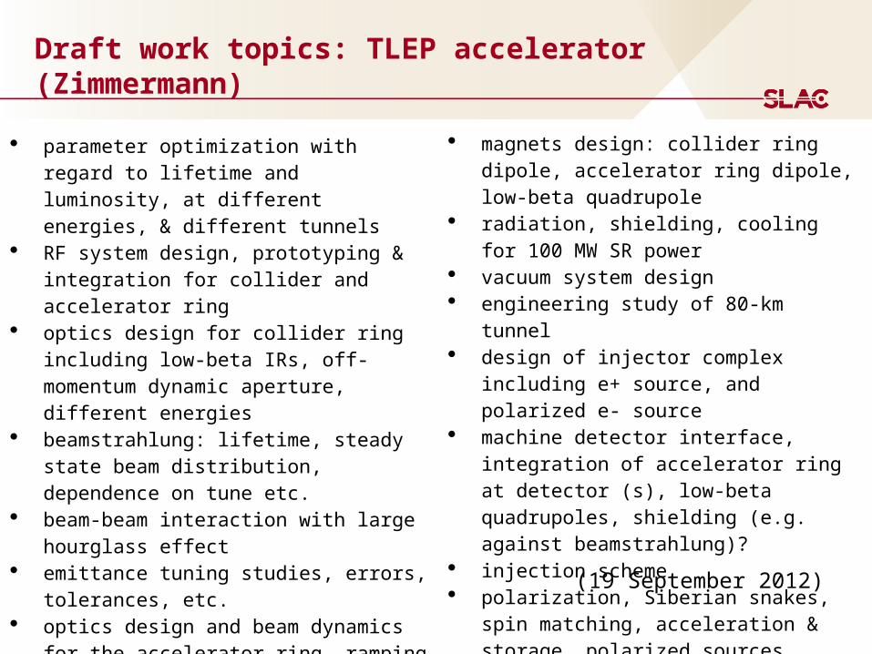
Draft work topics: TLEP accelerator (Zimmermann)
parameter optimization with regard to lifetime and luminosity, at different energies, & different tunnels
RF system design, prototyping & integration for collider and accelerator ring
optics design for collider ring including low-beta IRs, off-momentum dynamic aperture, different energies
beamstrahlung: lifetime, steady state beam distribution, dependence on tune etc.
beam-beam interaction with large hourglass effect
emittance tuning studies, errors, tolerances, etc.
optics design and beam dynamics for the accelerator ring, ramping speed etc
impedance budget, CSR, instabilities cryogenics system design
magnets design: collider ring dipole, accelerator ring dipole, low-beta quadrupole
radiation, shielding, cooling for 100 MW SR power
vacuum system design engineering study of 80-km tunnel design of injector complex including e+
source, and polarized e- source machine detector interface, integration of
accelerator ring at detector (s), low-beta quadrupoles, shielding (e.g. against beamstrahlung)?
injection scheme polarization, Siberian snakes, spin
matching, acceleration & storage, polarized sources
(19 September 2012)
39
F. Zimmermann comments April 4, 2013:
40
Seeman: Interaction Point Design
Key issues: 1 mm to 300 micron scale by*, large betas in IR quadrupoles,
quadrupoles inside the detector, collision feedback, vacuum chamber design,
magnet tolerances, alignment and jitter tolerances, crab cavities, crab waist,
US relevance: LHC, Muon collider, ILC, Higgs factory
Test accelerators/facilities: SuperKEKB, CESR-TA, PETRA-3, vibration
stabilization facility
Technologies:
100+ Hz IP dither feedback on luminosity
Superconducting magnets
Permanent magnets
Power supply stability
Vibration control
Non-linear optics
41
Seeman: Machine Detector Interface
Key issue: Synchrotron radiation backgrounds, lost particle
backgrounds, SR heating of vacuum chambers, radiation
damage/lifetime of detectors, sensor occupancy, luminosity
measurement.
US relevance: LHC, Muon collider, ILC, Higgs factory
Test accelerators/facilities: SuperKEKB, LHC, lab tests of
high power vacuum chambers, lab tests of detector lifetime
Technologies:
IP vacuum pumping
Advanced masking
Rapid luminosity feedback
Detector design
42
Seeman: Low Emittances
Key issue: Component tolerances, vibration control, emittance measuring
hardware, active feedbacks, field nonlinearities.
US relevance: ILC, Ultimate Storage Ring
Test accelerators/facilities: SuperKEKB, PETRA-3, CESR-TA, NSLS-II, lab tests
of x-ray size monitors
Technologies:
300 to1 emittance tuning techniques
Coherent Synchrotron Radiation CSR simulations and
measurements
Fast Ion Instability FII simulations and measurements
Intra-Beam Scattering IBS simulations and measurements
Electron Cloud Instability ECI simulations and measurements
Effects of spin rotators.
Effects of beam-beam interaction
43
Seeman: High Current Effects
Key issues: Beam stability, high power RF, high power vacuum
components, AC wall efficiency, injector capabilities, I> 1 A.
US relevance: LHC, muon collider, muon storage ring, Project X, Ultimate
Storage Ring
Test accelerators/facilities: SuperKEKB, CESR-TA
Technologies:
Better bunch feedbacks
ECI control
IBS mitigations
FII mitigations
More efficient klystrons
High power cavities
Longitudinal beam feedback
44
Seeman: Longitudinally Polarized e- Beam at the Interaction Point
Key issue: Injected polarization, beam lifetime, polarization
lifetime, spin rotators, polarization measurements, effect on IP
optics, beam-beam effect on polarization.
US relevance: ILC
Test accelerators/facilities: SuperKEKB?, VLEPP-2000?
Technologies:
Siberian snakes
Solenoidal rotators
Beam-beam depolarization diagnostics
Spin manipulation in the Damping Ring and Linac.
e- polarized source
45
Seeman: General Observations Lepton e+e- Colliders
Lattices:
x-y chromatic coupling in the IR is important: skew
sextupoles.
Sextupole and skew quadrupole coupling corrections in IR
More studies of IR error tolerances needed.
Instabilities:
More work on e-cloud to allow more bunches.
Beam-Beam Calculations:
Need mores studies of non-linear beam dynamics.
Parasitic crossing studies
Beam lifetimes:
Short beam lifetimes expected in the next collider (~10
minutes) with continuous top-off needed.
46
Seeman: Personal View
-Each region should follow their desires and strengths.
-Any new large accelerator should have a viable additional
energy or physics reach.
-Every region could build all these machines, but likely:
Asia: 250 GeV ILC capable of going to 1 TeV.
Europe: 250 GeV TLEP with a VHE-LHC add-on.
Americas: Muon Collider or PWFA Collider (equal for now)
with reach to several TeV.