Circular Connectors. Koehlke Circular Connectors hermaphroditic insert and screw fixing feature to...
28
[email protected] Koehlke Circular Connectors For Medical, Military, Test and Measurement, Alternative Energy, Auto, Aviation, Broadcast, Communications and Nuclear Applications Technical Data for B, K, C and P Series
Transcript of Circular Connectors. Koehlke Circular Connectors hermaphroditic insert and screw fixing feature to...

www.koehlke.com/CircularConnectorsCircularConnectors@[email protected]
ISO 9001:2008 / AS9100 Rev.B // ISO 14001 // RoHS compliant // ISO/TS16949 // IPC-A-610 // IPC/WHMA-A-620 // J-STD-001/002
KOeHlKe US HeADqUARTeRS KOeHlKe ASIA KOeHlKe eUROPe GmbH
Intuitive, solid feel• Generous lead-in and scoop-proof design•
These small connectors save space while improving performance•
nearly effortless push-pull latching mechanism•Thousandsofpossibleconfigurations•
Unique insert/housing combinations can be developed quickly•Affordably add quality and reliability to your end product•
When your application is too important to fail, choose Koehlke Circular Connectors.
.
*
Koehlke Circular ConnectorsFor Medical, Military, Test and Measurement,
Alternative Energy, Auto, Aviation, Broadcast, Communications and Nuclear Applications
©2011 Koehlke Components, Inc. All rights reserved. KI CC Short Form. Printed in the USA.
Koehlke Circular Connectors
* Registered trademarks: Fischer Connectors: Fischer Connectors SA; LEMO: LEMO SA; ODU: ODU-Steckverbindungssysteme GmbH. There is no association, cooperation, endorsement or sponsorship between Koehlke and Fischer Connectors, LEMO, ODU and/or any of their subsidiaries.
Technical Data for B, K, C and P Series

Koehlke Circular Connectors [email protected]
www.koehlke.com/CircularConnectors April 2011 - 2 -
Koehlke International, Ltd.
Table of Contents Features & Benefits ........................................................................................................................................................................................ 3 General Material Information ......................................................................................................................................................................... 3 Series Overview ............................................................................................................................................................................................... 4 B Series ............................................................................................................................................................................................................ 5
Features....................................................................................................................................................................................................... 5 Materials...................................................................................................................................................................................................... 5 Part Number ................................................................................................................................................................................................ 5
B Series Plugs.................................................................................................................................................................................................. 6 Shell Style “N” with Open Back.............................................................................................................................................................. 6 Shell Style “N” with Cable Bend Relief *............................................................................................................................................... 6
B Series Plugs (continued).............................................................................................................................................................................. 7 Shell Style “A” (Panel Mount) ................................................................................................................................................................. 7
B Series Receptacles ...................................................................................................................................................................................... 8 Shell Style “N”......................................................................................................................................................................................... 8 Fixed Front Ring ...................................................................................................................................................................................... 8 Shell Style “A” ......................................................................................................................................................................................... 8 Adjustable Front & Rear Rings ............................................................................................................................................................... 8 Shell Style “B”......................................................................................................................................................................................... 8 Fixed Rear Ring....................................................................................................................................................................................... 8 Shell Style “C” (Cable In-Line) ................................................................................................................................................................ 9 Shell Style “D” R/A PCB Mount............................................................................................................................................................ 10 Shell Style “E” R/X PCB Mount with Front & Rear Panel Lock Rings ................................................................................................. 10
B Series Receptacles (continued) ................................................................................................................................................................ 11 “D” and “E” Mating Contact and Solder Tail Configuration ................................................................................................................ 11
K Series .......................................................................................................................................................................................................... 12 Features..................................................................................................................................................................................................... 12 Materials.................................................................................................................................................................................................... 12 Part Number .............................................................................................................................................................................................. 12
K Series Plugs................................................................................................................................................................................................ 13 Shell Style “N” with Open Back............................................................................................................................................................ 13 Shell Style “N” with Cable Bend Relief *............................................................................................................................................. 13
K Series Receptacles .................................................................................................................................................................................... 14 Shell Style “N” Fixed Front Ring ........................................................................................................................................................... 14 Shell Style “B” Fixed Rear Ring ............................................................................................................................................................ 14 Shell Style “C” (Cable In-Line) .............................................................................................................................................................. 15
C Series .......................................................................................................................................................................................................... 16 Features..................................................................................................................................................................................................... 16 Materials.................................................................................................................................................................................................... 16 Part Number .............................................................................................................................................................................................. 16
C Series Plugs................................................................................................................................................................................................ 17 Shell Style “N” with Cable Bend Relief *............................................................................................................................................. 17 Shell Style “M” Vacuum Airproof.......................................................................................................................................................... 18
P Series .......................................................................................................................................................................................................... 19 Features..................................................................................................................................................................................................... 19 Materials.................................................................................................................................................................................................... 19 Part Number .............................................................................................................................................................................................. 19
P Series Plugs................................................................................................................................................................................................ 20 Shell Style “N” with Open Back............................................................................................................................................................ 20 Shell Style “N” with Cable Bend Relief *............................................................................................................................................. 20
P Series Receptacles .................................................................................................................................................................................... 21 Shell Style “A” Adjustable Front & Rear Rings ..................................................................................................................................... 21
Pin Configurations ......................................................................................................................................................................................... 22 Panel Cutout Configurations......................................................................................................................................................................... 24 PCB Hole Patterns for Vertical Solder Applications .................................................................................................................................... 25 Cable Clamp Sizes......................................................................................................................................................................................... 26 Bend Relief Color and Size Codes ................................................................................................................................................................ 27 Index Key Configurations .............................................................................................................................................................................. 27

ISO 9001:2008 / AS9100 Rev.B // ISO 14001 // RoHS compliant // ISO/TS16949 // IPC-A-610 // IPC/WHMA-A-620 // J-STD-001/002
KOeHlKe US HeADqUARTeRS KOeHlKe ASIA KOeHlKe eUROPe GmbH
FeATUReS & BeneFITS
Intuitive, solid feel• from the push-to-lock, pull-to-unlock feature.Generous lead-in and scoop-proof design• allows operators to engage Koehlke Circular Connectors easily and quickly – even when blind mating is required.These small connectors save space while improving performance• . In the space of a double-stack USB panel interface, a Koehlke Circular Connector can carry twice as many signals with dramatically higher reliability and security.nearly effortless push-pull latching mechanism• is completely secure to prevent accidental release.Thousandsofpossibleconfigurations• from our basic shells coupled with a range of standard cable- and coax-ready inserts to meet nearly countless customer requirements.Unique insert/housing combinations can be developed quickly• to meet your special requirements and innovative new products. Affordably add quality and reliability to your end product• with the high-end look and feel of Koehlke Circular Connectors.
GeneRAl APPlICATIOnS
When your application is too important to fail, choose Koehlke Circular Connectors. Our components are used in applications that require high durability and high durability and high durability reliability. They are the right solution when you require a connector with easy operation and perfect function, even after thousands of mate-demate cycles in rugged environments.
Koehlke connectors are your solution for a wide range of industrial, test and diagnostic uses, including:
Medical Diagnostic Equipment•Industrial or Laboratory Test and Measurement•A/V Broadcast•Aviation or Flight Hardware•Communications Infrastructure•Military Vehicles and Weapon Systems•Nuclear and Alternative Energy Power Generation•Automotive and Other Assembly•
COnTACT TeRMInATIOn COnTACT BASTACT BASTACT e MATeRIAl• Solder to Cable • Male Pins: Brass• Solder to PCB • Female Sockets: BeCu
envIROnMenTAl SeAlS COnTACT PlTACT PlTACT ATInG• Fluorine Rubber • UnderPlate: Min 50u” Nickel• Perbunan • OverPlate: Min 30u” Gold
SHell InSeRTMatte Chrome Plated Brass** PPS**
** Brass/PPS is a good material combination for most applications. For special requirements, Koehlke will provide alternate material for the housings: aluminum for light weight, stainless steel for nuclear environments, etc. Similarly, the inserts can be made from a wide variety of polymers including Nylon, PTFE, PEEK, etc.
PUSH/PUll COnneCTORSTO COMPleTe YOURe YOURe Y DeMAnDInG APPlICATIOnS
Koehlke builds your engineering vision to life. Since 1976, Koehlke has delivered vital components and assemblies that work for you.
Koehlke Circular Connector products are versatile, like your project requirements. All Koehlke Circular Connectors are modular, small-to-midsize, push/pull latch, cable and PCB mounted, cylindrical interconnects.
Within the Koehlke Circular Connector family are 7 product series, each with specific mating and environmental attributes. Three are heavy-duty, metal-shell connectors differentiated by how they lock, how they are indexed and their environmental sealing capacity. A fourth group of plastic-bodied connectors are for lighter-duty, cost-sensitive and/or disposable applications. Watertight and vacuum-tight connectors are available in the product family. Koehlke Circular Connectors are used in applications where electromagnetic compatibility (EMC) is key, and are designed to carry very low resistance.
Most Koehlke Circular Connectors mate with products from LEMO®, ODU® and Fischer Connectors®*. P/N cross references are available.
Koehlke’s dedicated and knowledgeable team is available to discuss specifics for your application and help configure your best solution. Contact Koehlke Technical Sales at 877-KOEHLKE (877-563-4553) or [email protected].
Koehlke Circular ConnectorsFor Medical, Military, Test and Measurement,
Alternative Energy, Auto, Aviation, Broadcast, Communications and Nuclear Applications
©2011 Koehlke Components, Inc. All rights reserved. KI CC Short Form. Printed in the USA.
Koehlke Circular Connectors
* Registered trademarks: Fischer Connectors: Fischer Connectors SA; LEMO: LEMO SA; ODU: ODU-Steckverbindungssysteme GmbH. There is no association, cooperation, endorsement or sponsorship between Koehlke and Fischer Connectors, LEMO, ODU and/or any of their subsidiaries.

Don’t see the configuration you need? New configurations continually are created, and our engineers will work with you to build a connector to your requirements.
“P” SeRIeSThe “P” series with the IP50 rating is a plastic shell connector with cable collet and nut for fitting a bend relief. This version is available in 2 to 14 positions. The fixed socket has a plastic shell. Available front nut colors are: grey, blue, yellow, red, green and black. yellow, red, green and black.
“F” SeRIeSThe “F” series is a waterproof variation of the “C” connector with IP66 rating. It shares the unique latching system and the high reliability contacts of the “C” series but adds housing and cable seals to create strong protection from the environment. The “F” series is available in 2 to 14 positions.
“e” SeRIeSThe “E” series is a compact connector with classic high density contacts for tight working conditions. See data sheet for available configuration options.
The fixed socket has a protruding shell with hermaphroditic insert and screw fixing feature to the panel.
6 0.5 10 5 750
7 0.5 10 5 750
4 0.7 7.5 7 875
5 0.7 7.5 7 750
2
Serie
s B0
, K0
Cont
act D
iam
eter
(mm
)
Cont
act R
esis
tanc
e (m
Ω)
Curr
ent (
A)
Test
Vol
tage
(V)
Cont
act C
onfig
urat
ion
Cont
act C
ount
0.9 60.9 6 10 1000
3 0.9 60.9 6 10 875
9 0.5 10 5 7505 750
Series B0, K0
300
300
300
300
Oper
atin
g Vo
ltage
(v)
500
400
300
10 0.5 10 5 750 333
14 0.5 10 5 750 300
6 0.7 7.5 7 875 450
7 0.7 7.5 7 875 400
4 0.9 6 10 1000 500
5 0.9 6 10 875 450
2
Serie
s B1
, K1,
C1
Cont
act D
iam
eter
(mm
)
Cont
act R
esis
tanc
e (m
Ω)
Curr
ent (
A)
Test
Vol
tage
(V)
Oper
atin
g Vo
ltage
(v)
Cont
act C
onfig
urat
ion
Cont
act C
ount
1.3 51.3 5 14 1250 550
3 1.3 51.3 5 14 1000 500
8 0.7 7.5 7 8750.7 7.5 7 8750.7 7.5 7 8750.7 7.5 7 875 333
Series B1, K1, C1
12 0.7 7.5 7 1000 450
14 0.7 7.5 7 875 400
6 1.3 5 14 1250 500
8 0.9 6 10 1250 500
4 1.3 5 14 1500 750
5 1.3 5 14 1250 600
2
Serie
s B2
, K2
Cont
act D
iam
eter
(mm
)
Cont
act R
esis
tanc
e (m
Ω)
Curr
ent (
A)
Test
Vol
tage
(V)
Oper
atin
g Vo
ltage
(v)
Cont
act C
onfig
urat
ion
Cont
act C
ount
2.0 3 20 15002.0 3 20 15002.0 3 20 15002.0 3 20 1500 700
3 1.6 41.6 4 17 1500 800
10 0.9 60.9 6 10 1250 500
Series B2, K2
16 0.7 7.5 7 8750.7 7.5 7 8750.7 7.5 7 8750.7 7.5 7 875 366
19 0.7 7.5 7 8750.7 7.5 7 8750.7 7.5 7 8750.7 7.5 7 875 333
26 0.5 10 5 6665 666 300
5 1.6 4 15 1250 550
3
Serie
s B3
, C3
Cont
act D
iam
eter
(mm
)
Cont
act R
esis
tanc
e (m
Ω)
Curr
ent (
A)
Test
Vol
tage
(V)
Oper
atin
g Vo
ltage
(v)
Cont
act C
onfig
urat
ion
Cont
act C
ount
2.0 3 17 1500 550
4 2.0 3 17 1500 550
Series B3, C3
Series 1P
2
1.3
5
10
1250
3
1.3
5
10
1250
4
0.9
6
8
1250
5
0.9
6
8
1100
6
0.7
7.5
6
1000
7
0.7
7.5
6
1000
8
0.7
7.5
5
875
9
0.5
10
3
600
10
0.5
10
3
600
14
0.5
10
3
600
Pin Array
Contact Diameter (mm)
Contact Resistance (mΩ)
Current (A)
Test Voltage (V)
Operating Voltage (v)
No. of Pins
500 500 500 500 450 450 400 333 333 333
PinConfigurationsAll Koehlke Circular Connectors share some basic features, but each possesses unique benefits. Although we identify the differences between each series, applications served, and the most widely used configurations, our customers continually use these connectors in new ways. You challenge us to innovate configurations and continuously improve product features. Please contact Koehlke for technical assistance to determine what is best for your application.
“S” SeRIeSThe “S” series is built in the classic LEMO®-style configuration.*The Koehlke “S” has the improved push-pull latching system with a variety of shells and inserts. Shielded, non-keyed “S” connectors are popular for single coax and multi-ax contacts.
“S” is uniquely identified by the two knurled grip rings around the main body, and the half-moon or hermaphroditic insert shapes. There is a sole key configuration, resulting in a robust, easy to see and feel key. “S” is good for interchangeable cables; but if multiple similar, non-interchangeable cables are required, “B” or “K” is best.
“K” SeRIeSKoehlke Circular “K” series with the IP66 rating is the answer to applications requiring environmental sealing. They share the excellent push-pull latching system and configuration options of the “B” series, including a wide variety of inserts from 2 to 26 positions.
While very similar to the “B” series, “K”s are identifiable by the smooth nose and an isolated forward grip ring on the plug. The receptacle can be identified by the presence of O-rings and a full circular recessed insert.
“B” SeRIeSKoehlke Circular “B”s are the backbone of our product line. This series employs the excellent push-pull latching system, different sized shells, optional bend relief and a wide variety of inserts. The “B” series has several keying options for situations where multiple, similar cables are used with a single device.
They are identifiable by the concave ring around the plug where the lock tangs protrude, and by the nearly flush position of the full circular by the nearly flush position of the full circular insert on the receptacle.
“C” SeRIeSThe “C” series has a slightly different latching system that maximizes the RF shielding of the system. It borrows the insert/contact technology from all other proven series and the perimeter keying of the Koehlke “B” and “K”. Like the others, the “C” series has various shell sizes and a wide variety of inserts. The Koehlke “C” series is compatible with some ODU® and FischerConnectors®, but at a more cost-conscious price point.*
The “C” series plug is easily identifiable by the multiple locks around the forward perimeter. The receptacles are similar to the “B” series, but with an extra ring in the shell, creating 2 the “B” series, but with an extra ring in the shell, creating 2 concentric rings around the center insert.concentric rings around the center insert.
excellent push-pull latching system and configuration options of the “B” series, including a wide variety of inserts from 2 to
While very similar to the “B” series, “K”s are identifiable by the smooth nose and an isolated forward grip ring on the plug. The
Koehlke Circular Connectors
26 0.7 7.5 7 8750.7 7.5 7 8750.7 7.5 7 8750.7 7.5 7 875 333
30 0.7 7.5 7 8750.7 7.5 7 8750.7 7.5 7 8750.7 7.5 7 875 300
16 0.9 60.9 6 10 1250 450
18 0.9 60.9 6 10 1000 450
10 1.3 51.3 5 14 1250 450
12 0.9 60.9 6 10 1250 450
14 0.9 60.9 6 10 1250 450
20 0.7 7.5 7 8750.7 7.5 7 8750.7 7.5 7 8750.7 7.5 7 875 333
21 0.7 7.5 7 8750.7 7.5 7 8750.7 7.5 7 8750.7 7.5 7 875 333
24 0.7 7.5 7 8750.7 7.5 7 8750.7 7.5 7 8750.7 7.5 7 875 333
Call us at 877-KOEHLKE.

Koehlke Circular Connectors [email protected]
www.koehlke.com/CircularConnectors April 2011 - 5 -
Koehlke International, Ltd.
B Series
Features • Push/Pull Latching System • 4 Shell Sizes from 9.4 mm to 17.8 mm • Ready-made inserts for up to 26 power/signal contacts or single coax
(Custom configurations available with quick-turnaround) • Cable-to-Panel, Cable-to-PCB (Straight or R/A), or Cable-to-Cable Configurations • 4 common keying systems for connector alignment
(Custom keys available) • Electromagnetic Shielding for EMC and Low Insertion Loss
Materials • Plug and Receptacle Shell: Matte Chrome Plated Brass • Insert: PPS • Bend Relief Sleeve: Perbunan
Part Number
Q B 0 P N 0 5 N 3 0 N N
KI ID Series
ID Shell Size Insert Type Shell
Style Contact ID Key Cable ID Bend Relief/Type Termination
Q B 0 N 02 - 26 N:0° 1:None/1
1 A A:30°
See Table in
Back 2:None/2 Details Below
2
P: Plug R: Receptacle
B
Details Below B:45° N:Black/1
3 C E:60° A:Red/1 D B:Orange/1 E C:Yellow/1 D:Green/1
E:Blue/1
F: Grey/1 G:White/1 H:Brown/1
Contact ID Descriptor • 02 - 26: Standard array of signal pins
is detailed on Pages 24 and 25. • Custom configurations also available.
Termination Descriptor N: Solder to Cable (solder-cup) A: Crimp to Cable B: Straight Solder to PCB C: R/A Solder to PCB

Koehlke Circular Connectors [email protected]
www.koehlke.com/CircularConnectors April 2011 - 6 -
Koehlke International, Ltd.
B Series Plugs
Shell Style “N” with Open Back
Shell Style “N” with Cable Bend Relief *
Size A B C D * R S
B 0 9.4 35 25 24 8 8
B 1 12 42.4 31.4 30 10 9
B 2 15 49 36.8 36 13 13
B 3 17.8 67 52 42 16 15
Example P/N: QB0PN-05N30-NN Description B Series, 0-size, Straight Plug with 5 cable-solder contacts, 0º Key, ready for 2.6 - 3.0 mm cable and black bend relief Breakdown
Q: Koehlke Circular Connector Family B: B Series 0: Shell Size 0 P: Plug N: Standard Configuration 05: 5 Signal Contacts N: 0º Key 30: Cable-Grip Ready for 3 mm Cable Diameter N: Black Bend Relief N: Solder-to-Cable (solder-cup) Style Contacts
BC
R S
A
* Cable Bend Relief Features: D* (below)

Koehlke Circular Connectors [email protected]
www.koehlke.com/CircularConnectors April 2011 - 7 -
Koehlke International, Ltd.
B Series Plugs (continued)
Shell Style “A” (Panel Mount)
Size A B C D E F R S
B 0 10 12.3 M9*0.5 20 18.4 11.2 8.2 11
B 1 13.8 16 M12*1.0 23.5 22.5 12.5 10.5 14
B 2 18 19.2 M15*1.0 24.7 22.5 13.8 13.5 17
B 3 22 25 M18*1.0 30.84 29 17 16.5 22
Example P/N: QB1PA-07N00-0N Description B Series, 1-size, Panel Mount Style “A” Plug with 7 cable-solder contacts, 0º key, and no cable-grip (n/a) , no bend relief (n/a) Breakdown
Q: Koehlke Circular Connector Family B: B Series 1: Shell Size 1 P: Plug A: “A” Shell Style Plug 07: 7 Signal Contacts N: 0º Key 00: Non-Cable Diameter
0: No Bend Relief N: Solder-to-Cable (solder-cup) Style Contacts
D E
F
CA B
R S
Koehlke Circular Connectors [email protected]
www.koehlke.com/CircularConnectors April 2011 - 8 -
Koehlke International, Ltd.
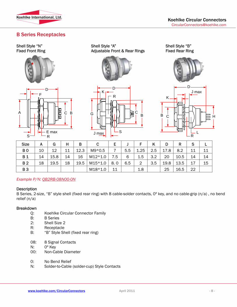
B Series Receptacles Shell Style “N” Fixed Front Ring
Shell Style “A” Adjustable Front & Rear Rings
Shell Style “B” Fixed Rear Ring
Size A G H B C E J F K D R S L
B 0 10 12 11 12.3 M9*0.5 7 5.5 1.25 2.5 17.8 8.2 11 11
B 1 14 15.8 14 16 M12*1.0 7.5 6 1.5 3.2 20 10.5 14 14
B 2 18 19.5 18 19.5 M15*1.0 8. 0 6.5 2 3.5 19.8 13.5 17 15
B 3 M18*1.0 11 1.8 25 16.5 22 Example P/N: QB2RB-08N00-0N Description B Series, 2-size, “B” style shell (fixed rear ring) with 8 cable-solder contacts, 0º key, and no cable-grip (n/a) , no bend relief (n/a) Breakdown
Q: Koehlke Circular Connector Family B: B Series 2: Shell Size 2 R: Receptacle B: “B” Style Shell (fixed rear ring) 08: 8 Signal Contacts N: 0º Key 00: Non-Cable Diameter 0: No Bend Relief N: Solder-to-Cable (solder-cup) Style Contacts
R S
F
E max
D
C B A G BC
J max
KD
R
S LR
D
K J max
C B H

Koehlke Circular Connectors [email protected]
www.koehlke.com/CircularConnectors April 2011 - 9 -
Koehlke International, Ltd.
B Series Receptacles (continued)
Shell Style “C” (Cable In-Line)
Example P/N: QB0RC-03N30-NN Description B Series, 0-size, In-line Style “C” Receptacle with 3 cable-solder contacts, 0º Key, and cable-grip for 3 mm cable, black bend relief Breakdown
Q: Koehlke Circular Connector Family B: B Series 0: Shell Size 0 R: Receptacle C: “C” Shell Style 03: 3 Signal Contacts N: 0º Key 30: Cable-Grip Ready for 3 mm Cable Diameter
N: Black Bend Relief N: Solder-to-Cable (solder-cup) Style Contacts
Size D A R D* S
B 0 33.4 8.8 8.0 24 8.0
B 1 41 12 9 30 10
B 2 47.2 14.5 13 36 13
* Cable Bend Relief Features: D* (below)
B
A
S R

Koehlke Circular Connectors [email protected]
www.koehlke.com/CircularConnectors April 2011 - 10 -
Koehlke International, Ltd.
B Series Receptacles (continued)
Shell Style “D” R/A PCB Mount
Shell Style “E”
R/X PCB Mount with Front & Rear Panel Lock Rings
Size A B C D E F I G H J R
B 0 25 13.3 11.7 12.7 6.7 9 12 14.6 0.7 M9*0.5 10
B 1 27 13.3 12.6 14 7.5 11 15 16.6 0.7 M11*0.5 13 Example P/N: QB1RE-07N00-0C Description B Series, 1-size, “E” Style Receptacle (with Panel Lock Rings) with 7 PCB-solder contacts, 0º Key, no cable grip (n/a) and no bend relief (n/a) Breakdown
Q: Koehlke Circular Connector Family B: B Series 1: Shell Size 1 R: Receptacle E: “E” Style Shell (includes Panel Lock Rings) 07: 7 Signal Contacts N: 0º Key 00: No Cable grip on “E” Receptacles 0: No Bend Relief on “E” Receptacles C: R/A Solder to PCB
A B
C
R
DE
I J
G H
D E
F
G H
A B
C
Koehlke Circular Connectors [email protected]
www.koehlke.com/CircularConnectors April 2011 - 11 -
Koehlke International, Ltd.
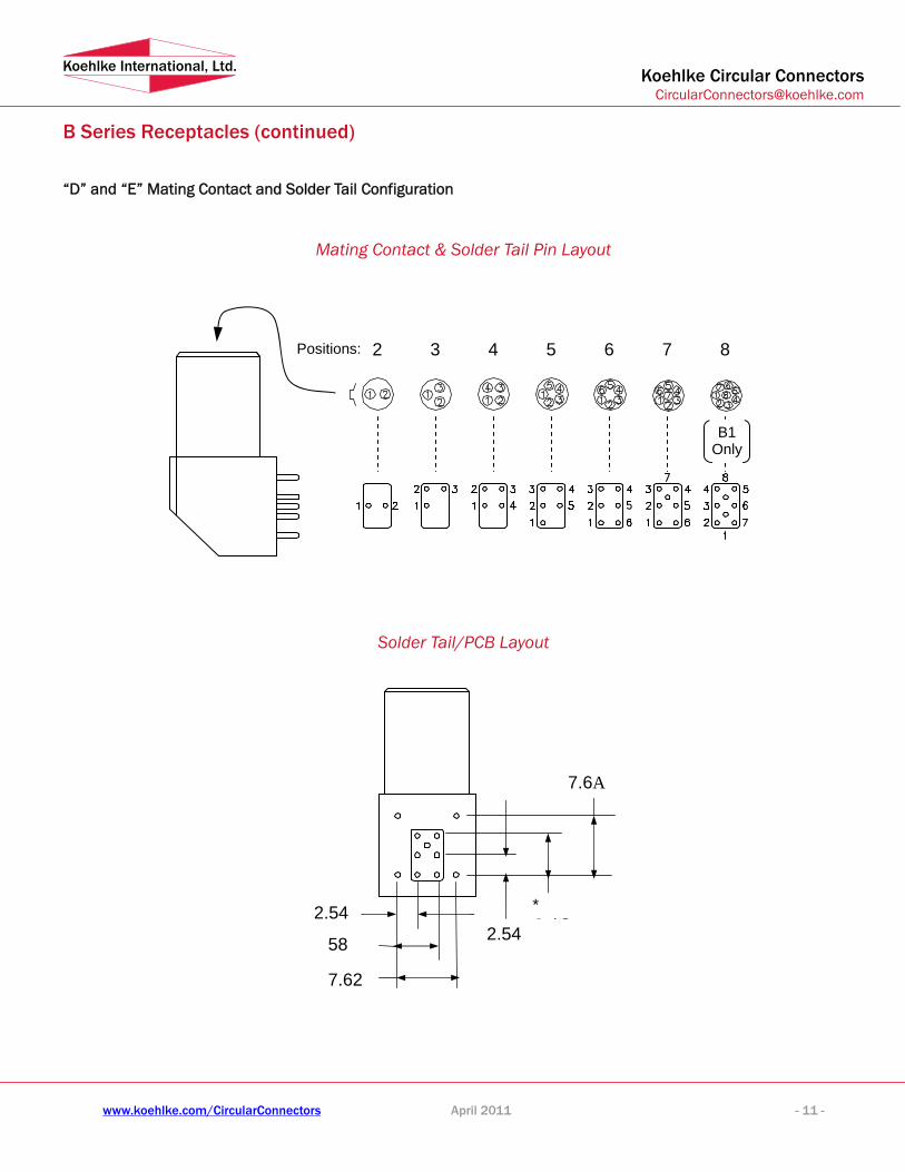
B Series Receptacles (continued)
“D” and “E” Mating Contact and Solder Tail Configuration
Mating Contact & Solder Tail Pin Layout
Solder Tail/PCB Layout
Positions: 2 3 4 5 6 7 8
B1 Only
2.54
58
7.62
2.54
* C bL
7.6A
Koehlke Circular Connectors [email protected]
www.koehlke.com/CircularConnectors April 2011 - 12 -
Koehlke International, Ltd.
Contact ID Descriptor • 02-26: Standard array of signal pins
is detailed on Pages 24 and 25. • Custom configurations also available.
Termination Descriptor N: Solder to Cable (solder-cup) A: Crimp to Cable B: Straight Solder to PCB C: R/A Solder to PCB
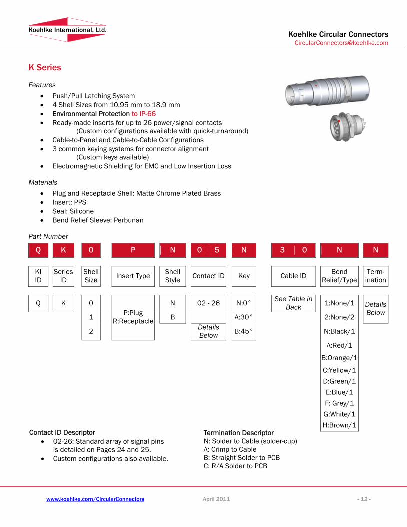
K Series
Features • Push/Pull Latching System • 4 Shell Sizes from 10.95 mm to 18.9 mm • Environmental Protection to IP-66 • Ready-made inserts for up to 26 power/signal contacts
(Custom configurations available with quick-turnaround) • Cable-to-Panel and Cable-to-Cable Configurations • 3 common keying systems for connector alignment
(Custom keys available) • Electromagnetic Shielding for EMC and Low Insertion Loss
Materials • Plug and Receptacle Shell: Matte Chrome Plated Brass • Insert: PPS • Seal: Silicone • Bend Relief Sleeve: Perbunan
Part Number
Q K 0 P N 0 5 N 3 0 N N
KI ID Series
ID Shell Size Insert Type Shell
Style Contact ID Key Cable ID Bend Relief/Type Term-
ination
Q K 0 N 02 - 26 N:0° See Table in Back 1:None/1
1 B A:30° 2:None/2
Details Below
2
P:Plug R:Receptacle
Details Below B:45° N:Black/1
A:Red/1
B:Orange/1
C:Yellow/1
D:Green/1
E:Blue/1
F: Grey/1
G:White/1 H:Brown/1

Koehlke Circular Connectors [email protected]
www.koehlke.com/CircularConnectors April 2011 - 13 -
Koehlke International, Ltd.
K Series Plugs
Shell Style “N” with Open Back
Shell Style “N” with Cable Bend Relief *
Size A B D* S
K 0 10.95 24 35 8
K 1 13 30 43.8 9
K 2 16 36 50.2 13
K 3 18.9 42 58.5 16
Example P/N: QK1PN-05N40-NN Description K Series, 1-size, Straight Plug with 5 cable-solder contacts, 0º key, ready for 3.6 - 4.0 mm cable and black bend relief
Breakdown
Q: Koehlke Circular Connector Family K: K Series 1: Shell Size 1 P: Plug N: Standard Configuration 05: 5 Signal Contacts N: 0º Key 40: Cable-Grip Ready for 3.6 to 4.0 mm Cable Diameter N: Black Bend Relief N: Solder-to-Cable (solder-cup) Style Contacts
S
D
A
* Cable Bend Relief Features: D* (below)

Koehlke Circular Connectors [email protected]
www.koehlke.com/CircularConnectors April 2011 - 14 -
Koehlke International, Ltd.
K Series Receptacles
Shell Style “N” Fixed Front Ring
Shell Style “B” Fixed Rear Ring
Size A H B C E J F K D R S
K 0 18 18 M14*1.0 7 5.5 4 19 12.5 17
K 1 20 20 21.9 M16*1.0 7.5 6 4.5 10 24.2 14.5 19
K 2 25 25 27.7 M20*1.0 8. 0 6.5 5 10 23.7 18.5 24 Example P/N: QK2RB-08N00-0N Description K Series, 2-size, “B” style shell (fixed rear ring) with 8 cable-solder contacts, 0º Key, and no cable-grip (n/a) , no bend relief (n/a) Breakdown
Q: Koehlke Circular Connector Family K: K Series 2: Shell Size 2 R: Receptacle B: “B” Style Shell (fixed rear ring) 08: 8 signal contacts N: 0º Key 00: Non-Cable Diameter 0: No Bend Relief N: Solder-to-Cable (solder-cup) Style Contacts
R
D
J max
C A H
K
S R
F
E max
D
C B A
Koehlke Circular Connectors [email protected]
www.koehlke.com/CircularConnectors April 2011 - 15 -
Koehlke International, Ltd.
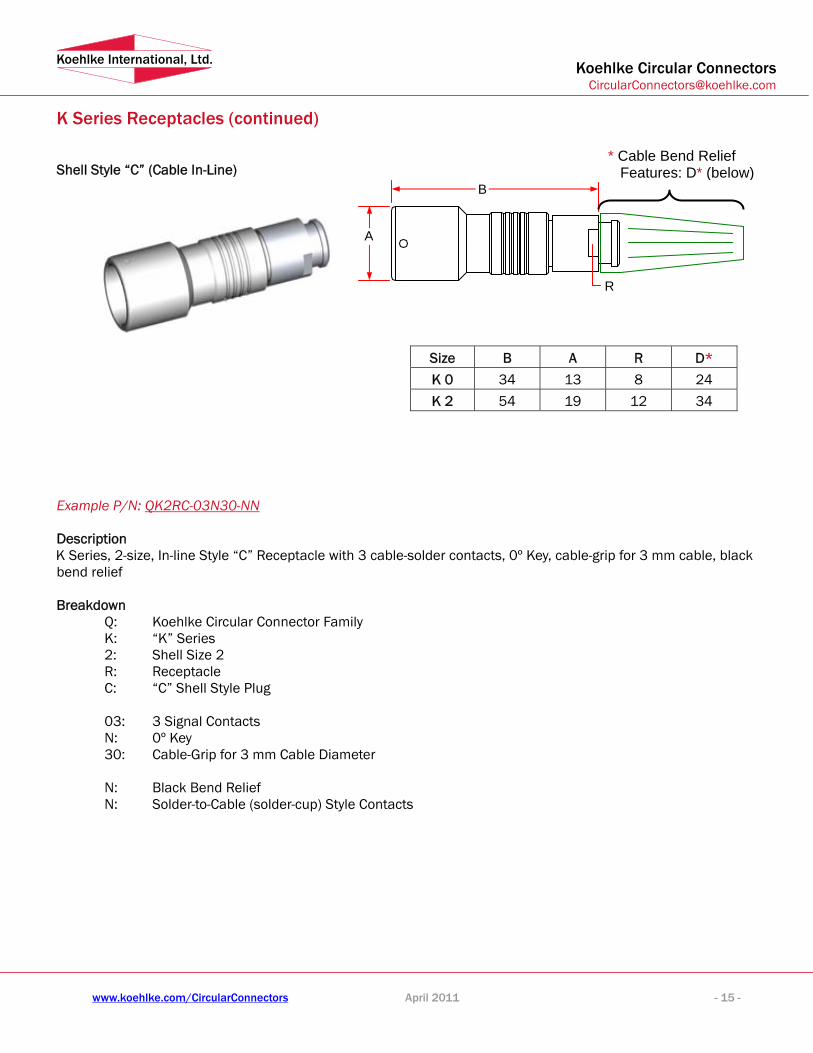
K Series Receptacles (continued)
Shell Style “C” (Cable In-Line)
Size B A R D*
K 0 34 13 8 24
K 2 54 19 12 34
Example P/N: QK2RC-03N30-NN Description K Series, 2-size, In-line Style “C” Receptacle with 3 cable-solder contacts, 0º Key, cable-grip for 3 mm cable, black bend relief Breakdown
Q: Koehlke Circular Connector Family K: “K” Series 2: Shell Size 2 R: Receptacle C: “C” Shell Style Plug 03: 3 Signal Contacts N: 0º Key 30: Cable-Grip for 3 mm Cable Diameter N: Black Bend Relief N: Solder-to-Cable (solder-cup) Style Contacts
B
A
R
* Cable Bend Relief Features: D* (below)

Koehlke Circular Connectors [email protected]
www.koehlke.com/CircularConnectors April 2011 - 16 -
Koehlke International, Ltd.
C Series
Features • Push/Pull Latching System • 2 Shell Sizes from 12mm and 18mm • Environmental Protection to IP-67 • Ready-made inserts for up to 21 power/signal contacts
(Custom configurations available with quick-turnaround) • Cable-to-Panel and Cable-to-Cable Configurations • 0° common keying system for connector alignment
(Custom keys available) • Electromagnetic Shielding for EMC and Low Insertion Loss
Materials • Plug and Receptacle Shell: Matte Chrome Plated Brass • Insert: PPS • Bend Relief Sleeve: Perbunan
Part Number
Q C 0 P N 0 5 N 3 0 N N
KI ID Series
ID Shell Size Insert Type Shell
Style Contact ID Key Cable ID Bend Relief Termination
Q C 1 N 2 - 21 N: 0° 0:None 3 M N:Black
Details Below
P: Plug R: Receptacle
Details Below A:Red
See Table in
Back B:Orange
C:Yellow D:Green E:Blue F: Grey
G:White
H: Brown Contact ID Descriptor
• 2 - 21: Standard array of signal pins is detailed on Pages 24 and 25.
• Custom configurations also available.
Termination Descriptor N: Solder to Cable (solder-cup) A: Crimp to Cable B: Straight Solder to PCB C: R/A Solder to PCB

Koehlke Circular Connectors [email protected]
www.koehlke.com/CircularConnectors April 2011 - 17 -
Koehlke International, Ltd.
C Series Plugs
Shell Style “N” with Cable Bend Relief *
Size A L C D* S
C 1 11.8 45.3 34.3 30 10
C 3 18 58.5 43.3 42 16
Example P/N: QC1PN-05N40-NN Description C Series, 1-size, Straight Plug with 5 cable-solder contacts, 0° Key, ready for 3.6 - 4.0 mm cable and black bend relief Breakdown
Q: Koehlke Circular Connector Family C: C Series 1: Shell Size 1 P: Plug N: Standard Configuration 05: 5 Signal Contacts N: 0° Key 40: Cable-Grip Ready for 4 mm Cable Diameter N: Black Bend Relief N: Solder-to-Cable (solder-cup) Style Contacts
A
C
L
S
* Cable Bend Relief Features: D* (below)

Koehlke Circular Connectors [email protected]
www.koehlke.com/CircularConnectors April 2011 - 18 -
Koehlke International, Ltd.
C Series Receptacles
Shell Style “M” Vacuum Airproof
Example P/N: QC3RM-04N00-0N Description C Series, 3-size, “M” Style shell (Vacuum airproof) Receptacle with 4 cable-solder contacts, 0º Key, no cable-grip and no bend relief Breakdown
Q: Koehlke Circular Connector Family C: C Series 3: Shell Size 3 R: Receptacle M: “M” Shell Style (Vacuum airproof) 04: 4 Signal Contacts N: 0º Key 00: Non -Cable 0: No Bend Relief N: Solder-to-Cable (solder-cup) Style Contacts
Size A D M N C R S
C 1 18.8 31.2 6 27.2 M14*1.0 12 17
C 3 26 32 6 28.5 M20*10 18 23
R
D
C A
S
N M

Koehlke Circular Connectors [email protected]
www.koehlke.com/CircularConnectors April 2011 - 19 -
Koehlke International, Ltd.
Contact ID Descriptor • 02 - 14: Standard array of signal pins
is detailed on Pages 24 and 25. • Custom configurations also available.
Termination Descriptor N: Solder to Cable (solder-cup) A: Crimp to Cable B: Straight Solder to PCB C: R/A Solder to PCB
P Series
Features • Push/Pull self-latching system • Shell Sizes just 14 mm • Environmental Protection to IP-50 • Ready-made inserts for up to 14 power/signal contacts
(Custom configurations available with quick-turnaround) • Cable-to-Panel and Cable-to-Cable Configurations • 4 common keying systems for connector alignment
(Custom keys available) • Electromagnetic Shielding for EMC and Low Insertion Loss
Materials • Plug and Receptacle Shell: Plastic shell type • Insert: PPS • Bend Relief Sleeve: Perbunan
Part Number
Q P 1 P N 0 5 N 3 0 N N
KI ID Series
ID Shell Size Insert Type Shell
Style Contact ID Key Collet Code
Bend Relief/Type 1;Collet Nut Color/Type 2
Termi-nation
Q P 1 N 02-14 N:0° 1:None/1 A A:40° 2:Black/2
Details Below
P: Plug R: Receptacle
Details Below
Details Below B:60° 3:Red/2
C:80°
42:4.0 below
52:5.0-4.0 62:6.0-5.0
4:Yellow/2 5:Green/2 6:Blue/2 7:Grey/2 N: Black/1
A:Red/1
C: Yellow/1 D: Green/1 E: Blue/1 F: Grey/1

Koehlke Circular Connectors [email protected]
www.koehlke.com/CircularConnectors April 2011 - 20 -
Koehlke International, Ltd.
P Series Plugs
Shell Style “N” with Open Back
Shell Style “N” with Cable Bend Relief *
Size A B C D* S
P1 14 44.5 29.4 30 9.0
Example P/N: QP1PN-05N52-NN Description P Series, 1-size, Straight Plug with 5 cable-solder contacts, 0º Key, ready for 4.0 - 5.0 mm cable and black bend relief/Type 1 Breakdown
Q: Koehlke Circular Connector Family P: P Series 1: Shell Size 1 P: Plug N: Standard Configuration 05: 5 Signal Contacts N: 0º Key 52: Cable-Grip Ready for 4.0 - 5.0 mm Cable Diameter N: Black Bend Relief/Type1 N: Solder-to-Cable (solder-cup) Style Contacts
* Cable Bend Relief Features: D* (below)

Koehlke Circular Connectors [email protected]
www.koehlke.com/CircularConnectors April 2011 - 21 -
Koehlke International, Ltd.
P Series Receptacles
Shell Style “A” Adjustable Front & Rear Rings
Example P/N: QP1RA-03N00-NN Description P Series, 1-size, “A” style shell (Adjustable Front & Rear Rings) receptacle with 3 cable-solder contacts, 0º key, and no cable-grip with black collet nut Breakdown
Q: Koehlke Circular Connector Family P: P Series 1: Shell Size 1 R: Receptacle A: “A” Shell Style (Adjustable Front & Rear Rings) 03: 3 Signal Contacts N: 0º Key 00: Non-Cable N: Black Collet Nut N: Solder-to-Cable (solder-cup) Style Contacts

Don’t see the configuration you need? New configurations continually are created, and our engineers will work with you to build a connector to your requirements.
“P” SeRIeSThe “P” series with the IP50 rating is a plastic shell connector with cable collet and nut for fitting a bend relief. This version is available in 2 to 14 positions. The fixed socket has a plastic shell. Available front nut colors are: grey, blue, yellow, red, green and black. yellow, red, green and black.
“F” SeRIeSThe “F” series is a waterproof variation of the “C” connector with IP66 rating. It shares the unique latching system and the high reliability contacts of the “C” series but adds housing and cable seals to create strong protection from the environment. The “F” series is available in 2 to 14 positions.
“e” SeRIeSThe “E” series is a compact connector with classic high density contacts for tight working conditions. See data sheet for available configuration options.
The fixed socket has a protruding shell with hermaphroditic insert and screw fixing feature to the panel.
6 0.5 10 5 750
7 0.5 10 5 750
4 0.7 7.5 7 875
5 0.7 7.5 7 750
2
Serie
s B0
, K0
Cont
act D
iam
eter
(mm
)
Cont
act R
esis
tanc
e (m
Ω)
Curr
ent (
A)
Test
Vol
tage
(V)
Cont
act C
onfig
urat
ion
Cont
act C
ount
0.9 60.9 6 10 1000
3 0.9 60.9 6 10 875
9 0.5 10 5 7505 750
Series B0, K0
300
300
300
300
Oper
atin
g Vo
ltage
(v)
500
400
300
10 0.5 10 5 750 333
14 0.5 10 5 750 300
6 0.7 7.5 7 875 450
7 0.7 7.5 7 875 400
4 0.9 6 10 1000 500
5 0.9 6 10 875 450
2
Serie
s B1
, K1,
C1
Cont
act D
iam
eter
(mm
)
Cont
act R
esis
tanc
e (m
Ω)
Curr
ent (
A)
Test
Vol
tage
(V)
Oper
atin
g Vo
ltage
(v)
Cont
act C
onfig
urat
ion
Cont
act C
ount
1.3 51.3 5 14 1250 550
3 1.3 51.3 5 14 1000 500
8 0.7 7.5 7 8750.7 7.5 7 8750.7 7.5 7 8750.7 7.5 7 875 333
Series B1, K1, C1
12 0.7 7.5 7 1000 450
14 0.7 7.5 7 875 400
6 1.3 5 14 1250 500
8 0.9 6 10 1250 500
4 1.3 5 14 1500 750
5 1.3 5 14 1250 600
2
Serie
s B2
, K2
Cont
act D
iam
eter
(mm
)
Cont
act R
esis
tanc
e (m
Ω)
Curr
ent (
A)
Test
Vol
tage
(V)
Oper
atin
g Vo
ltage
(v)
Cont
act C
onfig
urat
ion
Cont
act C
ount
2.0 3 20 15002.0 3 20 15002.0 3 20 15002.0 3 20 1500 700
3 1.6 41.6 4 17 1500 800
10 0.9 60.9 6 10 1250 500
Series B2, K2
16 0.7 7.5 7 8750.7 7.5 7 8750.7 7.5 7 8750.7 7.5 7 875 366
19 0.7 7.5 7 8750.7 7.5 7 8750.7 7.5 7 8750.7 7.5 7 875 333
26 0.5 10 5 6665 666 300
5 1.6 4 15 1250 550
3
Serie
s B3
, C3
Cont
act D
iam
eter
(mm
)
Cont
act R
esis
tanc
e (m
Ω)
Curr
ent (
A)
Test
Vol
tage
(V)
Oper
atin
g Vo
ltage
(v)
Cont
act C
onfig
urat
ion
Cont
act C
ount
2.0 3 17 1500 550
4 2.0 3 17 1500 550
Series B3, C3
Series 1P
2
1.3
5
10
1250
3
1.3
5
10
1250
4
0.9
6
8
1250
5
0.9
6
8
1100
6
0.7
7.5
6
1000
7
0.7
7.5
6
1000
8
0.7
7.5
5
875
9
0.5
10
3
600
10
0.5
10
3
600
14
0.5
10
3
600
Pin Array
Contact Diameter (mm)
Contact Resistance (mΩ)
Current (A)
Test Voltage (V)
Operating Voltage (v)
No. of Pins
500 500 500 500 450 450 400 333 333 333
PinConfigurationsAll Koehlke Circular Connectors share some basic features, but each possesses unique benefits. Although we identify the differences between each series, applications served, and the most widely used configurations, our customers continually use these connectors in new ways. You challenge us to innovate configurations and continuously improve product features. Please contact Koehlke for technical assistance to determine what is best for your application.
“S” SeRIeSThe “S” series is built in the classic LEMO®-style configuration.*The Koehlke “S” has the improved push-pull latching system with a variety of shells and inserts. Shielded, non-keyed “S” connectors are popular for single coax and multi-ax contacts.
“S” is uniquely identified by the two knurled grip rings around the main body, and the half-moon or hermaphroditic insert shapes. There is a sole key configuration, resulting in a robust, easy to see and feel key. “S” is good for interchangeable cables; but if multiple similar, non-interchangeable cables are required, “B” or “K” is best.
“K” SeRIeSKoehlke Circular “K” series with the IP66 rating is the answer to applications requiring environmental sealing. They share the excellent push-pull latching system and configuration options of the “B” series, including a wide variety of inserts from 2 to 26 positions.
While very similar to the “B” series, “K”s are identifiable by the smooth nose and an isolated forward grip ring on the plug. The receptacle can be identified by the presence of O-rings and a full circular recessed insert.
“B” SeRIeSKoehlke Circular “B”s are the backbone of our product line. This series employs the excellent push-pull latching system, different sized shells, optional bend relief and a wide variety of inserts. The “B” series has several keying options for situations where multiple, similar cables are used with a single device.
They are identifiable by the concave ring around the plug where the lock tangs protrude, and by the nearly flush position of the full circular by the nearly flush position of the full circular insert on the receptacle.
“C” SeRIeSThe “C” series has a slightly different latching system that maximizes the RF shielding of the system. It borrows the insert/contact technology from all other proven series and the perimeter keying of the Koehlke “B” and “K”. Like the others, the “C” series has various shell sizes and a wide variety of inserts. The Koehlke “C” series is compatible with some ODU® and FischerConnectors®, but at a more cost-conscious price point.*
The “C” series plug is easily identifiable by the multiple locks around the forward perimeter. The receptacles are similar to the “B” series, but with an extra ring in the shell, creating 2 the “B” series, but with an extra ring in the shell, creating 2 concentric rings around the center insert.concentric rings around the center insert.
excellent push-pull latching system and configuration options of the “B” series, including a wide variety of inserts from 2 to
While very similar to the “B” series, “K”s are identifiable by the smooth nose and an isolated forward grip ring on the plug. The
Koehlke Circular Connectors
26 0.7 7.5 7 8750.7 7.5 7 8750.7 7.5 7 8750.7 7.5 7 875 333
30 0.7 7.5 7 8750.7 7.5 7 8750.7 7.5 7 8750.7 7.5 7 875 300
16 0.9 60.9 6 10 1250 450
18 0.9 60.9 6 10 1000 450
10 1.3 51.3 5 14 1250 450
12 0.9 60.9 6 10 1250 450
14 0.9 60.9 6 10 1250 450
20 0.7 7.5 7 8750.7 7.5 7 8750.7 7.5 7 8750.7 7.5 7 875 333
21 0.7 7.5 7 8750.7 7.5 7 8750.7 7.5 7 8750.7 7.5 7 875 333
24 0.7 7.5 7 8750.7 7.5 7 8750.7 7.5 7 8750.7 7.5 7 875 333
Call us at 877-KOEHLKE.

Koehlke Circular Connectors [email protected]
www.koehlke.com/CircularConnectors April 2011 - 24 -
Koehlke International, Ltd.
Panel Cutout Configurations
Style/Size B0 B1 B2 B3 K0 K1 K2 S0 S1
A 8.3 10.6 13.6 16.6 12.5 14.6 18.6 8.3 10.6
D 9.1 12.1 15.1 18.1 14.1 16.1 20.1 9.1 12.1

Koehlke Circular Connectors [email protected]
www.koehlke.com/CircularConnectors April 2011 - 25 -
Koehlke International, Ltd.
PCB Hole Patterns for Vertical Solder Applications
# of Pins type B0 B1 B2 # of Pins type B0 B1 B2
A 0.8 0.8 0.8
A 0.8 0.8 0.8
02 D 2.2 2.8 4.4
03 D 2.3 3.0 4.6
A 0.6 0.8 0.8
A 0.6 0.8 0.8
04 D 2.5 3.1 5.0
05 D 2.8 3.4 5.2
A 0.6 0.8
A 0.8
06 D 3.0 3.7
06 D
5.6
A 0.6 0.8 0.8
A 0.8
07 D 3.0 3.7 5.8
08 D
3.8
A 0.6 0.8 A 0.8
H 1.4 2.15
08 D
6.4 10 D
3.95 6.20
A 0.8
A 0.6 0.8
H 6.5 H 1.8 2.65
12 D
2.8 14 D
4.4 6.5
A 0.8
A 0.8
H 3.10
H 3.50
16 D
6.60
19 D
6.7

Koehlke Circular Connectors [email protected]
www.koehlke.com/CircularConnectors April 2011 - 26 -
Koehlke International, Ltd.
Cable Clamp Sizes
B Series Code Cable Dia 00 0B 1B 2B 3B
25 2.0-2.5 ● ●
30 2.6-3.0 ● ●
35 3.1-3.5 ● ● ●
40 3.6-4.0 ● ● ●
45 4.1-4.5 ● ● ● ●
50 4.6-5.0 ● ● ● ●
60 5.1-6.0 ● ● ●
70 6.1-7.0 ● ● ●
80 7.1-8.0 ● ●
90 8.1-9.0 ● ●
01 9.1-10.0 ● ●
K Series Code Cable Dia 0K 1K 2K
40 3.6-4.0 ● ●
45 4.1-4.5 ● ●
50 4.6-5.0 ● ● ●
60 5.1-6.0 ● ●
70 6.1-7.0 ● ●
75 7.1-7.5 ●
80 7.6-8.0 ●
85 8.1-8.5 ●

Koehlke Circular Connectors [email protected]
www.koehlke.com/CircularConnectors April 2011 - 27 -
Koehlke International, Ltd.
Bend Relief Color and Size Codes Bend Relief Size Codes Bend Relief Color Codes
Color Code
None X
Black N
Red A
Orange B
Yellow C
Green D
Blue E
grey F
White G
Brown H
Index Key Configurations
Key Drawing Angle B0 B1 B2 B3 K0 K1 K2 K3
N
0° ◆ ◆ ◆ ◆ ◆ ◆ ◆ ◆
A
30° ◆ ◆ ◆ ◆ ◆ ◆
B
45° ◆ ◆ ◆ ◆ ◆
E
60° ◆ ◆
X (No Key: for Single-Contact Applications)
Code Cable Dia B0/K0 B1/K1 B2/K2 B325 2.5 - 2.9 ●30 3.0 - 3.4 ● ●35 3.5 - 3.9 ● ●40 4.0 - 4.4 ● ● ●45 4.5 - 5.0 ● ● ●51 5.1 - 5.6 ● ● ●57 5.7 - 6.2 ● ● ●63 6.3 - 7.0 ● ● ●71 7.1 - 7.9 ● ● ●80 8.0 - 8.9 ● ●90 9.0 - 9.9 ● ●01 10.0 - 10.5 ●

www.koehlke.com/[email protected]
ISO 9001:2008 / AS9100 Rev.B // ISO 14001 // RoHS compliant // ISO/TS16949 // IPC-A-610 // IPC/WHMA-A-620 // J-STD-001/002
KOeHlKe US HeADqUARTeRS1201 Commerce Center Drive
Franklin, Ohio 45005United States
(P) 877.KOEHLKE (877.563.4553)(F) 937.435.5435Cage Code: 5N063
KOeHlKe ASIA13F-1, No.268, Sec.1, WénHuà Road
Banciao City, Taipei County 22041 Taiwan (R.O.C.)
(P) 886.2.8258.1958(F) 886.2.8258.1998
VAT No. 28568764
KOeHlKe eUROPe GmbHAlte Landstraße 25D-85521 Ottobrunn
Germany(P) 49.89.66550889(F) 49.89.66078877
A privately-held family operation, Koehlke began in 1976 as a spare parts provider. Today, we stand as a worldwide supplier of material produced and assembled at the Koehlke facilities, franchised lines and Koehlke-approved sources of supply. We know what it takes to deliver vital components and assemblies, and are committed to value-added measures for our customers in every business phase, from product development to transactional service to exceptional customer follow up.
We service customers located throughout the United States including the U.S. Government, Lockheed Martin, Boeing, Raytheon, Space and Airborne Systems, Northrop Grumman, Schlumberger, Rockwell, Delphi, Oracle, LXE, Siemens AD, G&D, DELL, HP and Flextronics. Additionally, we service international exporters, and foreign corporations and governments. With our Koehlke International Asia partner, we bring together global efficiency and quality with Midwestern personable service and support.
OUR COnneCTORS FeATURe:An intuitive, solid feel•Generous lead-in and scoop-proof design•Space saving design •Improved performance•nearly effortless push-pull latching mechanism•Thousands of possible configurations•Unique insert/housing combinations that can be quickly developed•An affordable way to add quality and reliability to your end product•
Intuitive, solid feel• Generous lead-in and scoop-proof design•
These small connectors save space while improving performance•
nearly effortless push-pull latching mechanism•Thousandsofpossibleconfigurations•
Unique insert/housing combinations can be developed quickly•Affordably add quality and reliability to your end product•
When your application is too important to fail, choose Koehlke Circular Connectors.
.
*
Koehlke Circular ConnectorsFor Medical, Military, Test and Measurement,
Alternative Energy, Auto, Aviation, Broadcast, Communications and Nuclear Applications
©2011 Koehlke Components, Inc. All rights reserved. KI CC Short Form. Printed in the USA.
Koehlke Circular Connectors
* Registered trademarks: Fischer Connectors: Fischer Connectors SA; LEMO: LEMO SA; ODU: ODU-Steckverbindungssysteme GmbH. There is no association, cooperation, endorsement or sponsorship between Koehlke and Fischer Connectors, LEMO, ODU and/or any of their subsidiaries.