Circular Antenna Array Synthesis Using Salp Swarm Optimization
5
BALKAN JOURNAL OF ELECTRICAL & COMPUTER ENGINEERING, Vol. 8, No. 4, October 2020 Copyright © BAJECE ISSN: 2147-284X http://dergipark.gov.tr/bajece Abstract— Salp Swarm Algorithm (SSA) is used to design an optimal non uniform circular antenna arrays. Salp Swarm Algorithm which mimics the swarming behavior of salps in oceans is a nature-inspired optimization method. As it is simple and easy to apply, it has been applied to many different problems in the literature. SSA method optimally determined the positions and amplitudes of the circular antenna array elements to obtain radiation patterns with a low maximum sidelobe level (MSL) and narrow half power beam width (HPBW). Different sizes of antennas with 8, 10 and 12 elements are discussed to demonstrate the capability of the SSA algorithm. The results of MSL and HPBW obtained by SSA for the synthesis of circular antenna arrays are better than other compared optimization methods. Index Terms— Salp swarm algorithm, synthesis of antenna array, circular arrays, maximum sidelobe levels. I. INTRODUCTION N RECENT years, the interest in antenna arrays with high- directionality and gain used in different areas such as wireless communication, mobile, sonar, radar has been increasing. The communication systems performance used in many different applications is highly dependent on the design of the antenna array used. Antenna arrays can be in different structures such as circular, linear and elliptic depending on their geometric structure. Circular Antenna Arrays (CAAs) among these antenna types have become very popular especially in radar, wireless and mobile communication systems. Unlike linear antenna arrays, circular antenna arrays cover all 360 o of azimuth coverage [1]. CAAs can scan the main beam in any direction without a major change. Also, CAAs are not affected by the mutual effect because they do not have edge elements [2]. Due to these advantages, the optimum design of CAAs is of great interest in the literature. There has been a lot of research in the last decade on CAAs synthesis, an important computational electromagnetic problem. In [3], a genetic algorithm is used for sidelobes reduction of circular antenna arrays by amplitude and position control. Shihab et al. proposed a particle swarm optimization method for design of CAAs with low sidelobes level [4]. A firefly algorithm is applied for circular array optimization in [5]. In [6], seeker optimization algorithm used Ali DURMUŞ, is with Department of Electricity and Energy, Vocational College, Kayseri University, Turkey (e-mail: [email protected]). https://orcid.org/ 0000-0001-8283-8496 Manuscript received April 02, 2020; accepted Oct 07, 2020. DOI: 10.17694/bajece.713444 for designing of circular and concentric circular antenna array for sidelobe reduction. Babayigit et.al. implemented Taguchi's optimization method to the synthesis of circular antenna arrays [7]. Hamza et.al. proposed a genetic algorithm to perform the beam steering and null placement in circular arrays [8]. In [9], moth flame optimization used for designing of linear and circular antenna array for sidelobe reduction. Jamunaa et.al proposed a symbiotic organisms search optimisation algorithm to design of a reconfigurable concentric circular array with phase-only controls differentiating the beams [10]. In [11] Multiverse Optimizer (MVO) and modified MVO are used to perform circular antenna array synthesis. Das et.al. proposed gray wolf optimization and particle swarm optimization with a distribution based update mechanism to design of circular arrays [12]. In [13], Electric Charged Particles Optimization is applied to optimal design of circular antenna array for sidelobe level reduction. In this paper, Salp Swarm Algorithm (SSA) is used to the synthesis of optimum circular antenna arrays. SSA which mimics the swarming behavior of salps in oceans is a nature- inspired optimization method [14]. Since SSA method is an up- to-date optimization technique, there are different studies for SSA in the literature in recent years [14-19]. The amplitudes of the circular antenna array elements are determined by SSA in order to obtain optimum radiation pattern with maximum sidelobe level (MSL) reduction and narrow half power beam width (HPBW). The problem of antenna array synthesis consist of HPBW and MSL constraints. SSA has achieved very good results that meet the constraints. HPBW and MSL values of the array patterns can be easily controlled by using SSA. The results obtained with SSA are compared with the results of other well-known optimization methods. SSA demonstrates better performance to synthesizing circular antenna arrays than the other compared optimization techniques. The rest of the paper is organized as follows: The problem formulation for circular antenna design is examined in Section 2. In Section 3, the SSA method is explained. Section 4 presents numerical results and conclusions are presented in Section 5. Circular Antenna Array Synthesis Using Salp Swarm Optimization A. DURMUŞ I 320
Transcript of Circular Antenna Array Synthesis Using Salp Swarm Optimization
BALKAN JOURNAL OF ELECTRICAL & COMPUTER ENGINEERING, Vol. 8, No. 4, October 2020
Copyright © BAJECE ISSN: 2147-284X http://dergipark.gov.tr/bajece
Abstract— Salp Swarm Algorithm (SSA) is used to design an
optimal non uniform circular antenna arrays. Salp Swarm
Algorithm which mimics the swarming behavior of salps in oceans
is a nature-inspired optimization method. As it is simple and easy
to apply, it has been applied to many different problems in the
literature. SSA method optimally determined the positions and
amplitudes of the circular antenna array elements to obtain
radiation patterns with a low maximum sidelobe level (MSL) and
narrow half power beam width (HPBW). Different sizes of
antennas with 8, 10 and 12 elements are discussed to demonstrate
the capability of the SSA algorithm. The results of MSL and
HPBW obtained by SSA for the synthesis of circular antenna
arrays are better than other compared optimization methods.
Index Terms— Salp swarm algorithm, synthesis of antenna
array, circular arrays, maximum sidelobe levels.
I. INTRODUCTION
N RECENT years, the interest in antenna arrays with high-
directionality and gain used in different areas such as wireless
communication, mobile, sonar, radar has been increasing. The
communication systems performance used in many different
applications is highly dependent on the design of the antenna
array used. Antenna arrays can be in different structures such as
circular, linear and elliptic depending on their geometric
structure. Circular Antenna Arrays (CAAs) among these
antenna types have become very popular especially in radar,
wireless and mobile communication systems. Unlike linear
antenna arrays, circular antenna arrays cover all 360o of azimuth
coverage [1]. CAAs can scan the main beam in any direction
without a major change. Also, CAAs are not affected by the
mutual effect because they do not have edge elements [2]. Due
to these advantages, the optimum design of CAAs is of great
interest in the literature. There has been a lot of research in the
last decade on CAAs synthesis, an important computational
electromagnetic problem. In [3], a genetic algorithm is used for
sidelobes reduction of circular antenna arrays by amplitude and
position control. Shihab et al. proposed a particle swarm
optimization method for design of CAAs with low sidelobes
level [4]. A firefly algorithm is applied for circular array
optimization in [5]. In [6], seeker optimization algorithm used
Ali DURMUŞ, is with Department of Electricity and Energy, Vocational College, Kayseri University, Turkey (e-mail: [email protected]).
https://orcid.org/ 0000-0001-8283-8496 Manuscript received April 02, 2020; accepted Oct 07, 2020. DOI: 10.17694/bajece.713444
for designing of circular and concentric circular antenna array
for sidelobe reduction. Babayigit et.al. implemented Taguchi's
optimization method to the synthesis of circular antenna arrays
[7]. Hamza et.al. proposed a genetic algorithm to perform the
beam steering and null placement in circular arrays [8]. In [9],
moth flame optimization used for designing of linear and
circular antenna array for sidelobe reduction. Jamunaa et.al
proposed a symbiotic organisms search optimisation algorithm
to design of a reconfigurable concentric circular array with
phase-only controls differentiating the beams [10]. In [11]
Multiverse Optimizer (MVO) and modified MVO are used to
perform circular antenna array synthesis. Das et.al. proposed
gray wolf optimization and particle swarm optimization with a
distribution based update mechanism to design of circular
arrays [12]. In [13], Electric Charged Particles Optimization is
applied to optimal design of circular antenna array for sidelobe
level reduction.
In this paper, Salp Swarm Algorithm (SSA) is used to the
synthesis of optimum circular antenna arrays. SSA which
mimics the swarming behavior of salps in oceans is a nature-
inspired optimization method [14]. Since SSA method is an up-
to-date optimization technique, there are different studies for
SSA in the literature in recent years [14-19]. The amplitudes of
the circular antenna array elements are determined by SSA in
order to obtain optimum radiation pattern with maximum
sidelobe level (MSL) reduction and narrow half power beam
width (HPBW). The problem of antenna array synthesis consist
of HPBW and MSL constraints. SSA has achieved very good
results that meet the constraints. HPBW and MSL values of the
array patterns can be easily controlled by using SSA. The
results obtained with SSA are compared with the results of
other well-known optimization methods. SSA demonstrates
better performance to synthesizing circular antenna arrays than
the other compared optimization techniques.
The rest of the paper is organized as follows: The problem
formulation for circular antenna design is examined in Section
2. In Section 3, the SSA method is explained. Section 4
presents numerical results and conclusions are presented in
Section 5.
Circular Antenna Array Synthesis Using Salp
Swarm Optimization
A. DURMUŞ
I
320

BALKAN JOURNAL OF ELECTRICAL & COMPUTER ENGINEERING, Vol. 8, No. 4, October 2020
Copyright © BAJECE ISSN: 2147-284X http://dergipark.gov.tr/bajece
II. PROBLEM FORMULATION FOR CIRCULAR ANTENNA
DESIGN
The circular antenna array with M elements is illustrated in
Fig. 1. The antenna array elements are non-uniformly placed in
a circle with radius a in the x-y plane In Fig. 1.
Fig.1: M-elements circular antenna array
Circular antenna array elements are assumed to be isotropic
sources with similar properties. The circular antenna array
factor is given by [1].
𝐴𝐹(𝜃) = ∑ 𝐼𝑛 ∙ 𝑒(𝑗.𝑘𝑎.cos(𝜃−𝜑𝑛)+𝛼𝑛)𝑀𝑛=1 (1)
𝑘𝑎 = ∑ 𝑑𝑖
𝑀𝑖=1 (2)
𝜑𝑛 = (2𝜋 ∙ ∑ 𝑑𝑖)𝑛
𝑖=1 /𝑘𝑎 (3)
𝛼𝑛 = −𝑘𝑎 ∙ cos (𝜃0 − 𝜑𝑛) (4)
where 𝛼𝑛 and In are the phase and amplitude values of the n-
th array element, respectively. The distance between the two
antenna arrays elements is indicated by 𝑑𝑖. k is the number of
wave. The angular position of the n-th array element in x-y
plane is denoted by 𝜑𝑛.
The cost function given in Equation 5 is used to designing
circular antenna arrays with the decreased HPBW and low MSL
values.
𝑇𝑐𝑜𝑠𝑡 = 𝑊𝑆𝐿𝐿 ∙ 𝑇𝑆𝐿𝐿 + 𝑊𝐻𝑃𝐵𝑊 ∙ 𝑇𝐻𝑃𝐵𝑊 (5)
where 𝑊𝑆𝐿𝐿 and 𝑊𝐻𝑃𝐵𝑊 are the weight factors. 𝑇𝑆𝐿𝐿 and
𝑇𝐻𝑃𝐵𝑊 are the functions used for suppressing the MSL and
decreasing HPBW values respectively. The function of 𝑇𝑆𝐿𝐿
can be formulated as follows,
𝑇𝑆𝐿𝐿 = ∫ 𝛽𝑆𝐿𝐿(𝜑) ∙ 𝑑𝜑 + ∫ 𝛽𝑆𝐿𝐿(𝜑) ∙ 𝑑𝜑𝜋
𝜑𝑛2
𝜑𝑛1
−𝜋 (6)
where 𝜑𝑛1 and 𝜑𝑛2 are the two angles at the first nulls on
each side of the main beam. 𝛽𝑆𝐿𝐿(𝜑) can be given as follows,
𝛽𝑆𝐿𝐿(𝜑) = {𝛾0(𝜑) − 𝑆𝐿𝐿𝑑 , 𝛾0(𝜑) > 𝑆𝐿𝐿𝑑 0, 𝑒𝑙𝑠𝑒𝑤ℎ𝑒𝑟𝑒
(7)
where 𝑆𝐿𝐿𝑑 is the desired value of MSL. 𝛾0(𝜑) is the array
factor in dB. The function 𝑇𝐻𝑃𝐵𝑊 can be formulated by
𝑇𝐻𝑃𝐵𝑊 = {𝑇𝑜 − 𝑇𝐻𝑃𝐵𝑊𝑚𝑎𝑥 , 𝑇𝑜 > 𝑇𝐻𝑃𝐵𝑊𝑚𝑎𝑥
0, 𝑒𝑙𝑠𝑒𝑤ℎ𝑒𝑟𝑒 (8)
where 𝑇𝐻𝑃𝐵𝑊𝑚𝑎𝑥 and 𝑇𝑜 are the desired maximum HPBW
and the value of HPBW obtained by SSA, respectively.
III. SALP SWARM ALGORITHM
The Salp Swarm Algorithm (SSA) is a novel optimization
methods proposed by S. Mirjalili, et al. SSA optimization
method simulate the swarming behavior of salps in ocean. Salps
are living creatures that move by pumping the water in their
bodies. The salps move in the depths of the ocean as flocks and
these structures are called salp chains. According to the position
of the individuals in the salp chain, the salps are divided into
two as followers and leaders. The chain of salps is shown in Fig.
2.
Fig. 2: The chain of salps
The position of each individual in the salps chain is defined
in the n dimensional solution space. n is the number of variables
to be solved in the optimization problems. The position of
leader salp is updated by using Equation 9 [8].
321
BALKAN JOURNAL OF ELECTRICAL & COMPUTER ENGINEERING, Vol. 8, No. 4, October 2020
Copyright © BAJECE ISSN: 2147-284X http://dergipark.gov.tr/bajece
𝑘𝑖1 = {
𝑥𝑖 + 𝑓1((𝑢𝑖 − 𝑙𝑖)𝑓2 + 𝑙𝑖) 𝑓3 ≥ 0
𝑥𝑖 − 𝑓1((𝑢𝑖 − 𝑙𝑖)𝑓2 + 𝑙𝑖) 𝑓3 < 0 (9)
where 𝑥𝑖 and 𝑘𝑖1 are the food position and the first salp
position in the i-th dimension respectively. 𝑙𝑖 and 𝑢𝑖
corresponds to lower and upper bound of the i-th dimension.
The 𝑓2 and 𝑓3 coefficients are random numbers generated in the
range [0,1]. The 𝑓1 coefficient is calculated from the expression
below
𝑓1 = 2𝑒−(4𝑑
𝐷)2
(10)
where D and d represent the maximum iterations number
and the current iteration number, respectively. The position of
the followers are updated by using equation 11.
𝑘𝑖𝑗
=1
2(𝑘𝑖
𝑗+ 𝑘𝑖
𝑗−1) (11)
Detailed information about SSA is given in the reference [8].
IV. NUMERICAL RESULTS
All simulation studies in this paper were done on a computer
with 16 Gb RAM and 2.6 GHz i7 processor. MATLAB is the
software program to implement SSA. The population parameter
of SSA is fixed to 40. The main goal of circular antenna array
synthesis problems is to achieve the lowest MSL and narrowest
HPBW values to improve radiation pattern quality. Both
position and amplitude values of circular antenna array
elements are determined using SSA to achieve the desired
radiation pattern with low MSL and narrow HPBW values.
Circular antenna arrays with 8, 10 and 12 elements are
examined to demonstrate the flexibility and performance of the
SSA method.
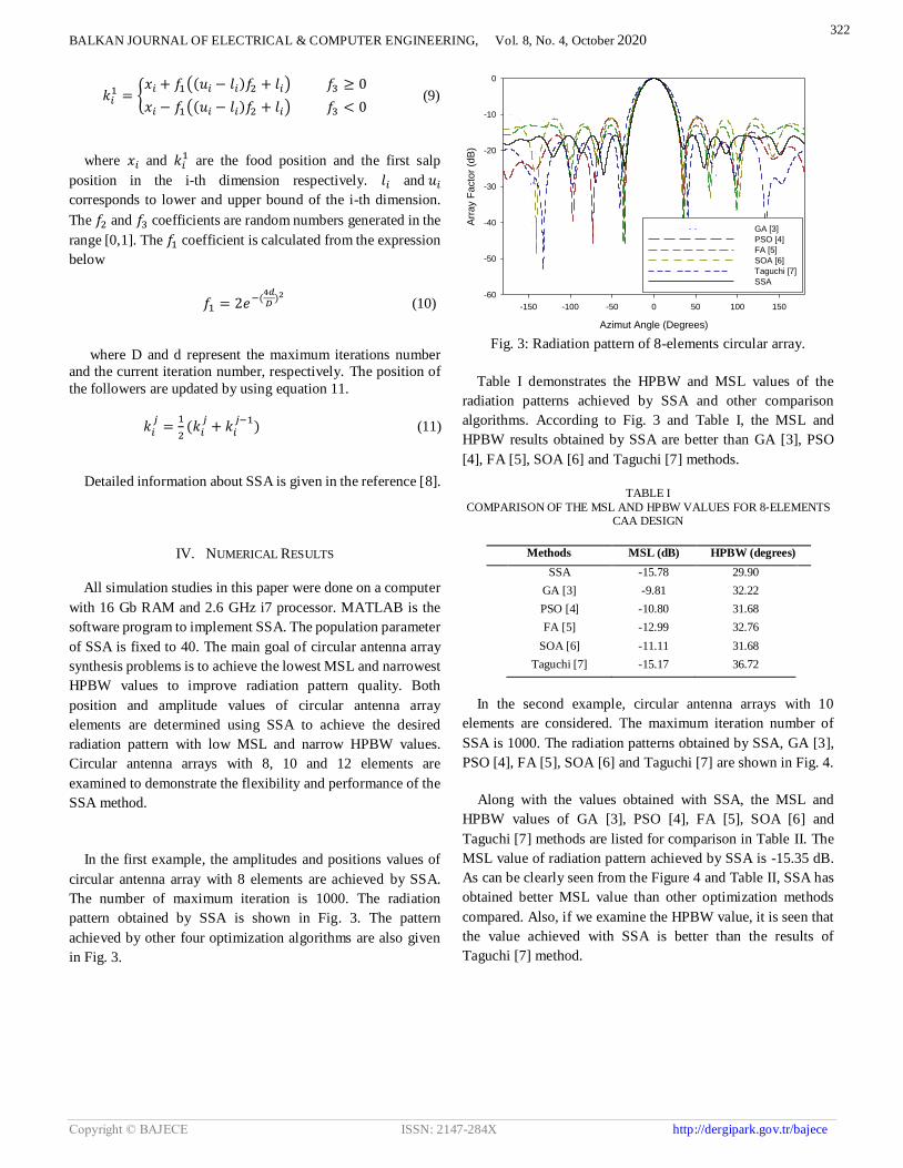
In the first example, the amplitudes and positions values of
circular antenna array with 8 elements are achieved by SSA.
The number of maximum iteration is 1000. The radiation
pattern obtained by SSA is shown in Fig. 3. The pattern
achieved by other four optimization algorithms are also given
in Fig. 3.
Azimut Angle (Degrees)
-150 -100 -50 0 50 100 150
Arr
ay F
acto
r (d
B)
-60
-50
-40
-30
-20
-10
0
GA [3]
PSO [4]
FA [5]
SOA [6]
Taguchi [7]
SSA
Fig. 3: Radiation pattern of 8-elements circular array.
Table I demonstrates the HPBW and MSL values of the
radiation patterns achieved by SSA and other comparison
algorithms. According to Fig. 3 and Table I, the MSL and
HPBW results obtained by SSA are better than GA [3], PSO
[4], FA [5], SOA [6] and Taguchi [7] methods.
TABLE I
COMPARISON OF THE MSL AND HPBW VALUES FOR 8‐ELEMENTS CAA DESIGN
Methods MSL (dB) HPBW (degrees)
SSA -15.78 29.90
GA [3] -9.81 32.22
PSO [4] -10.80 31.68
FA [5] -12.99 32.76
SOA [6] -11.11 31.68
Taguchi [7] -15.17 36.72
In the second example, circular antenna arrays with 10
elements are considered. The maximum iteration number of
SSA is 1000. The radiation patterns obtained by SSA, GA [3],
PSO [4], FA [5], SOA [6] and Taguchi [7] are shown in Fig. 4.
Along with the values obtained with SSA, the MSL and
HPBW values of GA [3], PSO [4], FA [5], SOA [6] and
Taguchi [7] methods are listed for comparison in Table II. The
MSL value of radiation pattern achieved by SSA is -15.35 dB.
As can be clearly seen from the Figure 4 and Table II, SSA has
obtained better MSL value than other optimization methods
compared. Also, if we examine the HPBW value, it is seen that
the value achieved with SSA is better than the results of
Taguchi [7] method.
322

BALKAN JOURNAL OF ELECTRICAL & COMPUTER ENGINEERING, Vol. 8, No. 4, October 2020
Copyright © BAJECE ISSN: 2147-284X http://dergipark.gov.tr/bajece
Azimut Angle (Degrees)
-150 -100 -50 0 50 100 150
Arr
ay F
acto
r (d
B)
-60
-50
-40
-30
-20
-10
0
GA [3]
PSO [4]
FA [5]
SOA [6]
Taguchi [7]
SSA
Fig. 4: Radiation pattern of 10-elements circular array.
TABLE II
COMPARISON OF THE MSL AND HPBW VALUES FOR 10‐ELEMENTS CAA DESIGN
Methods MSL (dB) HPBW (degrees)
SSA 15.35 29.11
GA [3] -10.85 25.56
PSO [4] -12.30 24.48
FA [5] -13.30 24.84
SOA [6] -12.50 24.12
Taguchi [7] -15.03 29.16
TABLE III
COMPARISON OF THE MSL AND HPBW VALUES FOR 12‐ELEMENTS CAA DESIGN
Methods MSL (dB) HPBW (degrees)
SSA -18.01 16.86
GA [3] -11.80 20.52
PSO [4] -13.67 20.88
FA [5] -14.20 20.52
SOA [6] -14.11 20.34
Taguchi [7] -17.68 16.92
In the last example, the SSA technique is used for
optimization of the circular antenna array with 12 elements. The
number of maximum iteration is has been set to 1000 to find
optimum solution. The radiation pattern obtained after
optimizing the position and amplitude values of the circular
arrays with SSA is shown in Fig. 5. MSL and HPBW values of
the radiation patterns are given in Table III comparatively. As
can be clearly seen from Table III, the MSL and HPBW values
obtained by SSA are better than that obtained by other
compared algorithms.
Azimut Angle (Degrees)
-150 -100 -50 0 50 100 150
Arr
ay F
acto
r (d
B)
-60
-50
-40
-30
-20
-10
0
GA [3]
PSO [4]
FA [5]
SOA [6]
Taguchi [7]
SSA
Fig. 5: Radiation pattern of 12-elements circular array.
The convergence curves obtained for 8, 10 and 12 element
circular antenna arrays design are given in Fig. 6.
Iteration Number
0 200 400 600 800 1000
Cost
Function
Valu
e
0
500
1000
1500
2000
2500
8-Elements
10-Elements
12-Elements
Fig. 6: The convergence curve of CAA with 8-elements,
10-elements and 12-elements.
Table IV tabulates the amplitudes and positions values of the
circular antenna array with 8, 10, and 12elements.
V. CONCLUSION
In this study, the position and amplitude values of the non-
uniform circular antenna arrays having 8, 12, and 20 isotropic
elements are optimized by SSA method. The radiation pattern
with low MSL and narrow HPBW values are obtained with the
proposed SSA algorithm. The results show that SSA is
successful in achieving radiation pattern with low MSL and
narrow HPBW for circular antenna array synthesis. Generally,
the MSL and HPBW values obtained with SSA are better than
the other compared algorithms. In addition, by making changes
in the algorithm and creating hybrid structures, better results
can be obtained in later studies.
323

BALKAN JOURNAL OF ELECTRICAL & COMPUTER ENGINEERING, Vol. 8, No. 4, October 2020
Copyright © BAJECE ISSN: 2147-284X http://dergipark.gov.tr/bajece
TABLE IV
THE AMPLITUDE AND POSITION VALUES OF NON‐UNIFORM CIRCULAR ARRAY WITH 8-ELEMENTS, 10-ELEMENTS, AND 12-ELEMENTS
Number of Elements
Amplitude Values
[I1, I2, I3, …….IM]
Inter Element Spacing
[d1, d2, d3, …….dM]
8-Elements (Fig. 3) [0.9369 0.3191 0.3704 0.6591 0.8065 0.3922 1.0000 0.4209] [0.3710 1.0107 0.3507 0.9704 0.5172 0.9543 1.4366 0.3050]
10-Elements (Fig. 4) [0.9004 0.3341 0.4454 0.9175 0.9828 0.1128 0.3362 0.9605 0.4788 0.3346]
[0.3543 0.9178 0.3616 1.0000 0.5707 0.8815 0.6296 0.8216 0.3513 0.0010]
12-Elements (Fig. 5) [0.5539 0.6489 0.2849 0.5421 0.3916 0.8903 0.9871 0.5434 0.6610 0.6229 0.5248 1.0000]
[0.5965 1.0456 0.6811 0.6726 0.8109 0.4747 0.5074 0.4959 0.9460 1.3183 1.0867 0.5625]
REFERENCES
[1] C. A. Balanis, Antenna theory: analysis and design, 3rd edn. Wiley, New York, 2005.
[2] J. R. Mailloux, Phased array antenna handbook. Artech House, Boston, 2005.
[3] M. A. Panduro, A. L. Mendez, R. Dominguez, G. Romero. "Design of non-uniform circular antenna arrays for side lobe reduction using the method of genetic algorithms." AEU Int. J. Electron Commun., vol.60.7, 2006, pp. 713–717.
[4] M. Shihab, Y. Najjar, N. Khodier. "Design of non-uniform circular antenna arrays using particle swarm optimization." J. Electr. Eng., vol. 59, 2008, pp. 216–220.
[5] A. Sharaqa, N. Dib. "Circular antenna array synthesis using firefly algorithm." Int. J. RF Microw. Comput. Eng., vol.24, 2014, pp. 139–146.
[6] K. Guney, S. Basbug. "A parallel implementation of seeker optimization algorithm for designing circular and concentric circular antenna arrays." Appl. Soft Comput. vol.22, 2014, pp. 287–296.
[7] B. Babayigit, E. Senyigit. "Design optimization of circular antenna arrays using Taguchi method." Neural Computing & Application, vol. 28, 2017, pp.1443-1452.
[8] A. Hamza, H. Attia, "Fast Beam Steering and Null Placement in an Adaptive Circular Antenna Array." IEEE Antennas and Wireless Propagation Letters, vol. 19, 2020, pp. 1561-1565.
[9] A. Das, D. Mandal, S.P. Ghoshal, R. Kar. "Moth flame optimization based design of linear and circular antenna array for side lobe reduction." International Journal of Numerical Modelling: Electronic Networks, Devices and Fields, vol. 32, 2019, pp.1-15.
[10] D. Jamunaa, F. N. Hasoon, G. K. Mahanti. "Symbiotic organisms search optimisation algorithm for synthesis of phase-only reconfigurable concentric circular antenna array with uniform amplitude distribution." International Journal of Electronics Letters, 2019, pp. 1-12.
[11] A. E. Taser, K. Guney, E. Kurt. "Circular Antenna Array Synthesis Using Multiverse Optimizer." International Journal of Antennas and Propagation, 2020.
[12] A. Das, D. Mandal, R. Kar. "An optimal circular antenna array design considering mutual coupling using heuristic approaches." International
Journal of RF and Microwave Computer‐Aided Engineering, 2020, pp. 1-14.
[13] H. R. E. H Bouchekara. "Electric Charged Particles Optimization and its application to the optimal design of a circular antenna array." Artificial Intelligence Review, 2020, pp. 1-36.
[14] S. Mirjalili, A. H. Gandomi, S. Z. Mirjalili, S. Saremi, H. Faris, S. M. Mirjalili. "Salp Swarm Algorithm: A bio-inspired optimizer for engineering design problems." Advances in Engineering Software, vol. 114, 2017, pp. 163-191.
[15] H. Faris, M. Mafarja, A. Heidari, I. Aljarah, A. Al-Zoubi, S. Mirjalili, et al. "An efficient binary salp swarm algorithm with crossover scheme for feature selection problems. " Knowledge-Based Systems, vol. 154, 2018, pp. 43–67.
[16] R. Abbassi, A. Abbassi, A. Heidari, S. Mirjalili. "An efficient salp swarm-inspired algorithm for parameters identification of photovoltaic cell models." Energy Conversion and Management, vol. 179, 2019, pp. 362–372.
[17] E. E. Elattar, S. K. ElSayed. "Probabilistic energy management with emission of renewable micro-grids including storage devices based on
efficient salp swarm algorithm." Renewable Energy, vol. 153, 2020, pp. 23-35.
[18] X. Zhao, P. Wu, X. Yin. "A quadratic penalty item optimal variational mode decomposition method based on single-objective salp swarm algorithm." Mechanical Systems and Signal Processing, vol. 138, 2020, p. 106567.
[19] W. Liu, R. Wang, J. Su. "An Image Impulsive Noise Denoising Method Based on Salp Swarm Algorithm." International Journal of Education and Management Engineering, vol. 10, 2020, p. 43.
Ali DURMUŞ was born in Kayseri, Turkey
in 1980. He received the B.Sc., M.Sc. and
Ph.D. degrees, all in Electrical and
Electronics Engineering, from Erciyes
University, Kayseri Turkey in 2003, 2005,
and 2016 respectively. He served as a
lecturer at the Department of Electricity
and Energy, Erciyes University from 2010
to 2018. Currently he is an assistant
professor at the Department of Electricity and Energy, Kayseri
University. His research interests are antennas, antenna arrays,
meta-heuristic algorithms, and computational electromagnetics.
324