Esquemas Elétricos HD SERIAL COMPACT ( Interface SCCE 022 V2) Scanchip
Upload
truongtuongCategory
view
217download
0
CESDig & CEletro 2018/19 - Elect. Fundamentals Floyd & Buchla © Pearson Education. © Trustees of Boston Un iversityJF 30-10-201823-10-2018
Circuitos Elétricos e Sistemas Digitais2018-2019 - 1.º Semestre
Fontes dependentes e teoremas de Thévenin e de Norto n
• Fontes independentes
• Fontes dependentes
• Circuitos lineares
• Princípio da sobreposição
• Teorema de Thévenin
• Teorema de Norton
• Teorema da máxima transferência de potência
CESDig 2018/2019 123-10-2018
CESDig & CEletro 2018/19 - Elect. Fundamentals Floyd & Buchla © Pearson Education. © Trustees of Boston Un iversityJF 30-10-201823-10-2018
Componentes de um circuito
2
• Um circuito pode conter componentes ativos e passiv os
• Os componentes ativos transformam energia não elétrica em energia elétrica
que fornecem ao circuito (e.g. fonte de tensão ou de corrente). Têm a capacidade
de promover o movimento de portadores de carga elétrica livres pelas diferentes
partes do circuito.
• Os componentes passivos não têm capacidade de adicionar energia ao circuito.
Podem contudo armazenar energia eletromagnética (e.g. condensadores e
bobines) ou transformar energia elétrica noutras formas de energia (e.g.
resistências).
• Fonte de tensão/corrente : pode ser independente (impõe aos seus terminais
uma diferença de potencial (ddp)/corrente pré-estabelecida) ou dependente
(impõe aos seus terminais uma ddp/corrente que é dependente do valor da ddp ou
da corrente noutra parte do circuito).
• As fontes independentes são representadas por círculos e as fontes
dependentes por losangos . Como vimos, uma bateria tem um símbolo próprio.

CESDig & CEletro 2018/19 - Elect. Fundamentals Floyd & Buchla © Pearson Education. © Trustees of Boston Un iversityJF 30-10-201823-10-2018
Fontes ideais vs fontes reais
3
• As fontes de tensão/corrente podem ser modelizadas por uma associação de
fontes ideais de tensão/corrente com uma resistência (dita resistência interna).
• Não existem fontes ideais (de tensão ou de corrente), pois, por definição, forçam
uma tensão ou uma corrente quaisquer que sejam as características do circuito
elétrico a que estão ligadas, o que levaria a algumas impossibilidades físicas.
• Uma fonte de tensão/corrente real também dissipa energia, embora se pretenda
que, comparativamente aos outros elementos do circuito dissipe muito menos.
• Numa fonte de tensão real a resistência “em associação” está em série com a
fonte ideal.
• Numa fonte de corrente real a resistência em associação está em paralelo com a
fonte de corrente ideal.
• Os elementos ativos podem comportar-se em certas circunstâ ncias como
elemento passivos, absorvendo energia em vez de fornecerem energia ao
circuito (e.g. bateria automóvel ou pilhas a recarregarem) .

CESDig & CEletro 2018/19 - Elect. Fundamentals Floyd & Buchla © Pearson Education. © Trustees of Boston Un iversityJF 30-10-201823-10-2018
Fontes independentes
Independent Current source
+_
Independent Voltage source
Up to now, we have only considered independent sources.
• The value of an independent source is fixed and does not depend on anything else in the circuit.
fixed values
• A dependent source depends on something else in the circuit.
4

CESDig & CEletro 2018/19 - Elect. Fundamentals Floyd & Buchla © Pearson Education. © Trustees of Boston Un iversityJF 30-10-201823-10-2018
Fontes dependentes
We will now discuss the concept of a dependent source.
• A dependent source depends on something else in the circuit.
• “Something else” (the controlling variable) can be a voltage, current, or other variable anywhere in the circuit.
controllingvariable
controllingvariable
Values dependson controllingvariable
Dependent Voltage source
+_
+v_
DependentCurrent source
i
5

CESDig & CEletro 2018/19 - Elect. Fundamentals Floyd & Buchla © Pearson Education. © Trustees of Boston Un iversityJF 30-10-201823-10-2018
Analogia com sistemas hidráulicos
TuboFonte independente(não há possibilidade de controlar o fluxo da água no tubo de controlo)
66
torneira
Fonte dependente(há possibilidade de controlo do fluxo da água)

CESDig & CEletro 2018/19 - Elect. Fundamentals Floyd & Buchla © Pearson Education. © Trustees of Boston Un iversityJF 30-10-201823-10-2018
Exemplo de um circuito com uma fonte dependente
vx = av1
+v1_
+v2_
+_
Q: If v1 = 4 V and a = 2, what is vx ?
+4 V
_= 8 V
A: vx = av1 = 2 • 4V = 8 V
If v1 changes, then vx will change also
5 V
= 10V
7

CESDig & CEletro 2018/19 - Elect. Fundamentals Floyd & Buchla © Pearson Education. © Trustees of Boston Un iversityJF 30-10-201823-10-2018
Resistência/impedância das fontes dependentes• Tal como acontece com as fontes independentes, a impedância das fontes de
tensão/corrente dependentes reais não é necessariamente nula/zero.
• Considere-se um circuito formado por uma fonte de tensão dependente em série
com uma resistência. Se se pretender determinar a resistência entre o terminal da
resistência e o terminal da fonte, pode aplicar-se uma corrente ao circuito através
de uma fonte de corrente ou de uma fonte de tensão. No case de se usar uma
fonte de corrente, tem-se o circuito abaixo, a direita.
• A resistência vista dos terminais referidos determina-se através da expressão:
= . Tendo em conta que =
= , obtém-se =
. De
onde resulta que a resistência da fonte dependente é, neste caso:
= − = 1 − .
v=a·vAB+_
RI0
+vAB
-v=a·vAB
+_R +
vAB
-
8

CESDig & CEletro 2018/19 - Elect. Fundamentals Floyd & Buchla © Pearson Education. © Trustees of Boston Un iversityJF 30-10-201823-10-2018
+_
A dependent voltage source can depend on a voltage :
v = u vb
value of this source
proportionality constant
voltage on which this source depends
vb
+_
A dependent voltage source can depend on a current (CCVS) :
+_ v = r ia
value of this source
proportionality constant
current on which this source depends
ia
Voltage controlled voltage source (VCVS)
Current controlled voltage source (CCVS)
9

CESDig & CEletro 2018/19 - Elect. Fundamentals Floyd & Buchla © Pearson Education. © Trustees of Boston Un iversityJF 30-10-201823-10-2018
↑↑↑↑
A dependent current source can depend on a voltage :
i = g vb
value of this source
proportionality constant
voltage on which this source depends
vb
+_
A dependent current source can depend on a current :
↑↑↑↑ i = β ib
value of this source
proportionality constant
current on which this source depends
ib
Voltage controlled current source (VCCS)
Current controlled current source (CCCS)
10

CESDig & CEletro 2018/19 - Elect. Fundamentals Floyd & Buchla © Pearson Education. © Trustees of Boston Un iversityJF 30-10-201823-10-2018
Os quatro tipos de fontes dependentes
+_ v = u vb
voltage-dependent voltage source
↑↑↑↑ i = g vb
voltage-dependent current source
↑↑↑↑ i = ββββ ib
current-dependent current source
+_ v = r ia
current-dependent voltage source
Proportionality Constants
Controlling Variables
Controlling Variables
adimensional V/A
A / Vadimensional
11

CESDig & CEletro 2018/19 - Elect. Fundamentals Floyd & Buchla © Pearson Education. © Trustees of Boston Un iversityJF 30-10-201823-10-2018
Exemplos de circuitos com fontes
dependentes
12

CESDig & CEletro 2018/19 - Elect. Fundamentals Floyd & Buchla © Pearson Education. © Trustees of Boston Un iversityJF 30-10-201823-10-2018
This circuit is a model for a guitar amplifier system:
• Multiply vmic by a large number• Apply as “amplified” voltage to loudspeaker• Sound comes out
Circuito amplificador
+_Avv1
ROUT
RIN
+v1–
GuitarPickup
Loud-speaker
Box 1 Box 2
+vmic–
Rmic
13

CESDig & CEletro 2018/19 - Elect. Fundamentals Floyd & Buchla © Pearson Education. © Trustees of Boston Un iversityJF 30-10-201823-10-2018
Modelo de um Transístor Bipolar
Equivalent Model
Rbe
iB
ββββ iB
iC
Base
Emitter
Collector
Device Symbol
B C
EiE
Um novo dispositivo: o transístor bipolar de junção (BJT):
= + Transístor bipolar:
Do ponto de vista da corrente, o transístor bipolar (BJT) comporta-se como um nodo
current-dependent current source
14

CESDig & CEletro 2018/19 - Elect. Fundamentals Floyd & Buchla © Pearson Education. © Trustees of Boston Un iversityJF 30-10-201823-10-2018
Equivalent ModelMOSFET
+vg
–gmvg
Modelo do MOSFET
Outro novo dispositivo: MOSFET (acrónimo de “Metal Oxide Semiconductor
Field Effect Transistor”, ou transístor de efeito de campo metal - óxido –
semicondutor)
voltage-dependent current source
15

CESDig & CEletro 2018/19 - Elect. Fundamentals Floyd & Buchla © Pearson Education. © Trustees of Boston Un iversityJF 30-10-201823-10-2018
Características tensão -corrente
de um elemento, de um circuito ou de
parte de um circuito
16

CESDig & CEletro 2018/19 - Elect. Fundamentals Floyd & Buchla © Pearson Education. © Trustees of Boston Un iversityJF 30-10-201823-10-2018
Definição da característica tensão-corrente (caract erística I-V)
A característica tensão-corrente de um elemento ou de uma porção de um circuito
descreve a relação entre a corrente que flui através do componente/circuito e a tensão
aos seus terminais. A tensão é a variável independente; a corrente é a variável
dependente.
A representação gráfica da característica I-V mostra os pares de valores de tensão e de
corrente permitidos na operação pelo dito elemento/circuito; os valores de tensão são
representados no eixo horizontal (abcissas) e os valores de corrente são representados
no eixo vertical (ordenadas).
Uma resistência, por exemplo, tem uma característica I-V qu e segue a lei de Ohm:
I=V/R. O gráfico desta característica I-V passa pela origem e tem um declive
dI/dV=1/R.
O conceito de característica tensão-corrente pode ser usado para descrever a relação
entre a corrente e a tensão entre dois pontos (porto ) quaisquer de um circuito ou de
uma porção de um circuito. Esta porção de circuito pode ser considerada como um
elemento com a sua própria característica I-V. O conceito de equação de tensão-
corrente pode ser aplicado a qualquer par de terminais de uma rede de vários
elementos, tal como mostra o exemplo que se segue.
17

CESDig & CEletro 2018/19 - Elect. Fundamentals Floyd & Buchla © Pearson Education. © Trustees of Boston Un iversityJF 30-10-201823-10-2018
Determinação da característica tensão-corrente de u m “circuito”
O conceito de uma equação de tensão-corrente pode ser aplicado a qualquer par de
terminais (ou porto) de qualquer rede de vários elementos. Deduzir e representar
graficamente a relação I-V para o porto A-B do circuito representado abaixo.
=5 V
=1 kΩ
IA Em aberto, a tensão aos terminais A-B será VTH, e a corrente IA será
nula. Quando se liga outro elemento aos terminais A-B do circuito
como uma resistência finita, por exemplo, fluirá uma corrente IA “para
fora” do terminal A, isto é, no sentido A→B. (Este “dispositivo” não é
passivo, porque contém uma fonte de tensão independente.)
Da aplicação da lei de Kirchhoff obtém-se a equação: VA=VTH-IARTH, resultando na relação: IA= -
VA/RTH + VTH/RTH.
O declive da relação IA=f(VA) é dado por dIA/dVA= - 1/RTH.
Representando graficamente a relação IA=f(VA) obtida, vemos que a característica I-V do
“circuito” intercepta o eixo IA (ordenadas) no ponto VTH/RTH e o eixo VA (abcissas) no ponto VTH.
18

CESDig & CEletro 2018/19 - Elect. Fundamentals Floyd & Buchla © Pearson Education. © Trustees of Boston Un iversityJF 30-10-201823-10-2018
Circuitos lineares
19
CESDig & CEletro 2018/19 - Elect. Fundamentals Floyd & Buchla © Pearson Education. © Trustees of Boston Un iversityJF 30-10-201823-10-2018
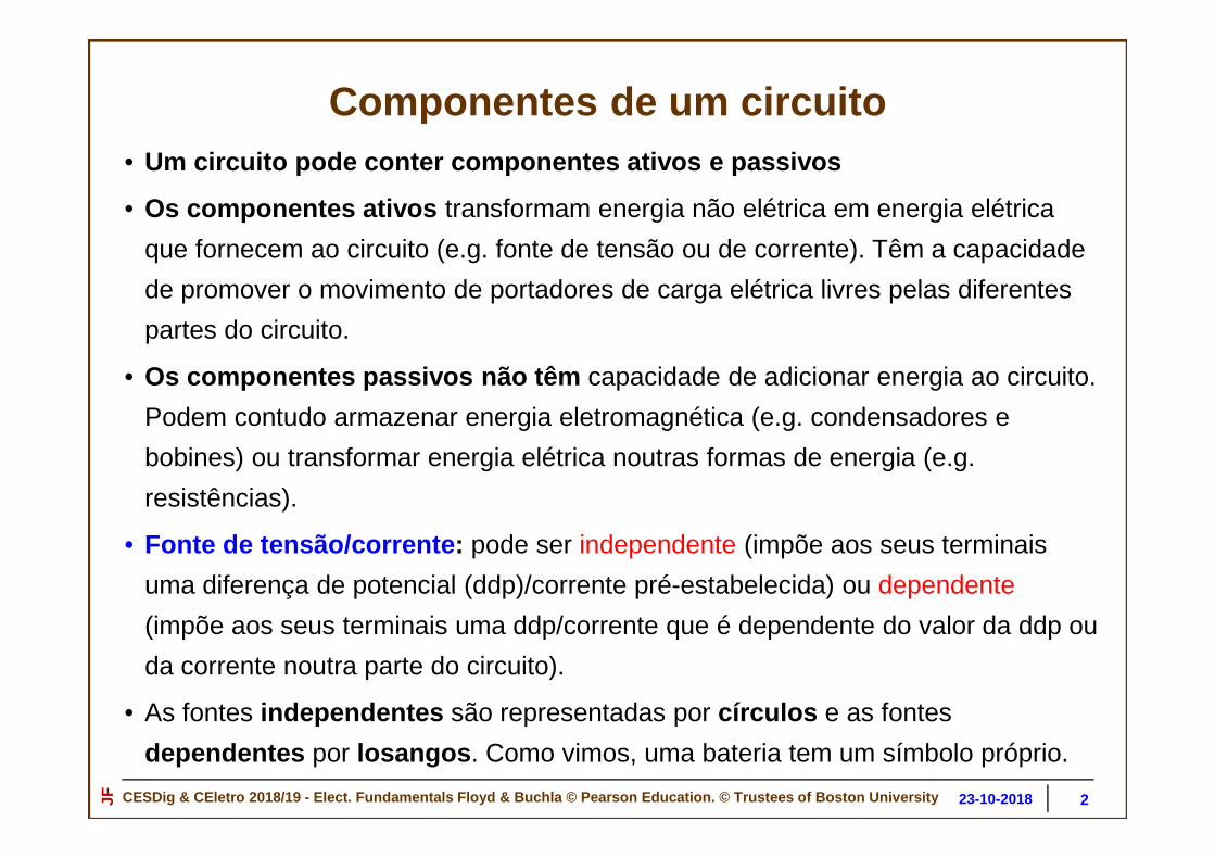
Circuitos linearesUm elemento de um circuito diz-se linear se tiver uma característica I-V da forma:
= + ou
= !" + #".
Nestas equações a, b, c, e d são constantes.
De uma forma mais geral, estes coeficientes também poderiam ser operadores
lineares como, por exemplo, derivadas ou integrais. Assim, um elemento de um
circuito que tenha uma característica V-I que possa ser escrita na forma:
= ##$ + % #$
também é um elemento de circuito linear.
Qualquer circuito formado a partir de elementos cujas características I-V possamser expressas nas formas descritas acima, obedecerá ao princípio dasobreposição.
20

CESDig & CEletro 2018/19 - Elect. Fundamentals Floyd & Buchla © Pearson Education. © Trustees of Boston Un iversityJF 30-10-201823-10-2018
Princípio da sobreposição
21

CESDig & CEletro 2018/19 - Elect. Fundamentals Floyd & Buchla © Pearson Education. © Trustees of Boston Un iversityJF 30-10-201823-10-2018
Princípio da sobreposição O princípio da sobreposição estabelece que a resposta de um circuito linear em
resultado da ação de todas fontes de tensão independentes presentes será igual à
soma das respostas devidas a cada fonte atuando isoladamente.
Seja, por exemplo, um circuito que produz uma corrente em resposta a uma
tensão aplicada " , = &(") , onde &(") é uma função linear da forma
expressa atrás ; Se for aplicada uma tensão distinta ", é gerada uma corrente da forma = &(").Se o circuito for linear , a corrente total resultante da aplicação simultânea de "e ", resulta numa corrente ) da forma:
) = &(" + ") = &(") + &(") = + .
Pode-se utilizar o principio da sobreposição para conhecer qualquer tensão ou
corrente num circuito linear , incluindo quando existem diversas fontes de tensão
e de corrente (lineares) no circuito.
22

CESDig & CEletro 2018/19 - Elect. Fundamentals Floyd & Buchla © Pearson Education. © Trustees of Boston Un iversityJF 30-10-201823-10-2018
Princípio da Sobreposição
Alguns circuitos possuem mais que uma fonte de tensão. Por exemplo, certo tipo
de amplificadores requerem para operação fontes de tensão com ambas as
polaridades (fontes bipolares) .
O princípio da sobreposição permite determinar correntes e tensões em
circuitos lineares com várias fontes de tensão, consideran do uma fonte de
cada vez, com as outras fontes substituídas pelas respectiva s
resistências/impedâncias internas .
Isto é, a corrente em qualquer ramo de um circuito linear com várias fontes pode
ser obtida determinando a corrente em cada ramo produzida por cada fonte
actuando isoladamente, com todas as outras fontes substituídas pelas suas
resistências/impedâncias internas.
A corrente em cada ramo será a soma algébrica das correntes nesse ramo
devidas às fontes individuais.
23

CESDig & CEletro 2018/19 - Elect. Fundamentals Floyd & Buchla © Pearson Education. © Trustees of Boston Un iversityJF 30-10-201823-10-2018
Exemplo: Circuito com duas fontes de tensão independentes
Queremos determinar I2:
24

CESDig & CEletro 2018/19 - Elect. Fundamentals Floyd & Buchla © Pearson Education. © Trustees of Boston Un iversityJF 30-10-201823-10-2018
Aplicação do princípio da Sobreposição
Metodologia:
• Considera-se uma fonte de tensão/corrente de cada vez, substituindo as outras
fontes de tensão por curto-circuitos e pelas respectivas
resistências/impedâncias internas, e as outras fontes de corrente substituídas
por circuitos-abertos em paralelo com as respectivas resistências/impedâncias
internas; as fontes dependentes continuam a ser tidas em conta , a menos
que não façam parte da secção do circuito em consideração.
• determinar cada corrente e tensão particular, para cada fonte considerada;
• considerar nova fonte e repetir os passos anteriores;
• adicionar ou subtrair as componentes das correntes em cada ramo devidas a
cada fonte individual;
• uma vez conhecida a corrente obtém-se a tensão, usando a lei de Ohm.
25

CESDig & CEletro 2018/19 - Elect. Fundamentals Floyd & Buchla © Pearson Education. © Trustees of Boston Un iversityJF 30-10-201823-10-2018
Efeito de Vs1 Efeito de Vs2
I2
I2(S2)
A corrente no ramo com a R2 é dada porI2=I2(S2)+I2(S1)
I2(S1)
Exemplo: Circuito com duas fontes de tensão independentes
Determinar a corrente que percorre R2, I2=I2(S2)+I2(S1)
26

CESDig & CEletro 2018/19 - Elect. Fundamentals Floyd & Buchla © Pearson Education. © Trustees of Boston Un iversityJF 30-10-201823-10-2018
Princípio da sobreposição
The superposition theoremis a way to determine currents and voltages in a linear circuit that has multiple sources by taking one source at a time and algebraically summing the results.
What does the ammeter read for I2?
+-
-
+
-
+
R1 R3
R2
I2
VS2VS1
12 V
2.7 kΩ 6.8 kΩ
6.8 kΩ
18 V
27

CESDig & CEletro 2018/19 - Elect. Fundamentals Floyd & Buchla © Pearson Education. © Trustees of Boston Un iversityJF 30-10-201823-10-2018
Princípio da sobreposição
6.10 kΩ
Qual é o valor da corrente I2 medido pelo amperímetro?
1.97 mA 0.98 mA
8.73 kΩ 2.06 mA
+-
-
+
-
+
R1 R3
R2
I2
VS2VS1
12 V
2.7 kΩ 6.8 kΩ
6.8 kΩ
18 V
0.58 mA
1.56 mA
Source 1: RT(S1)= I1= I2=
Source 2: RT(S2)= I3= I2=
Both sources I2=
Set up a table of pertinent information and solve for each quantity listed:
The total current is the algebraic sum.
+ -
-
+
R1 R3
R2
I2VS1
12 V
2.7 kΩ 6.8 kΩ
6.8 kΩ
+ -
-
+
R1 R3
R2
I2
VS2
2.7 kΩ 6.8 kΩ
6.8 kΩ
18 V+-
-
+
-
+
R1 R3
R2
I2
VS2VS1
12 V
2.7 kΩ 6.8 kΩ
6.8 kΩ
18 V1.56 mA
1) Efeito de VS1: substitui-se VS2 por um curto, determina-se a resistência vista por VS1, RT(S1) e a corrente que percorre VS1, 1.97 mA; pelo divisor de corrente determina-se I2(S1).
2) Efeito de VS2: idem.
28

CESDig & CEletro 2018/19 - Elect. Fundamentals Floyd & Buchla © Pearson Education. © Trustees of Boston Un iversityJF 30-10-201823-10-2018
Exercício de aplicação do princípio da sobreposição1. Considere o circuito da figura. i) Usando o principio da sobreposição determine a
tensão "* (tensão em circuito aberto, "+,, i.e., sem carga). ii) Determine a correntede curto circuito -, entre X e X’. iii) Represente graficamente a característicatensão-corrente * − "*. Res: i) 1,67 V + 0,33 V + 5 V = 7 V; ii) 2.1 mA;
2. Determine o valor e o sentido da corrente que percorre a resistência R2, se v1=10 V,v2= 4 V, I0=4 mA, e R1=R2=10 k Ω. Res: 2,7 mA.
3. Determine o valor e o sentido da corrente que percorre a resistência R2, se v1=10 V,v2= 4 V, I0=-4 mA, e R1=R2=10 k Ω. Res: -1,3 mA.
29

CESDig & CEletro 2018/19 - Elect. Fundamentals Floyd & Buchla © Pearson Education. © Trustees of Boston Un iversityJF 30-10-201823-10-2018
Teorema de Thévenin
CESDig 2018/2019 30
CESDig & CEletro 2018/19 - Elect. Fundamentals Floyd & Buchla © Pearson Education. © Trustees of Boston Un iversityJF 30-10-201823-10-2018
Teorema de Thévenin
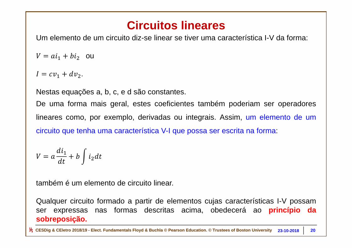
Thevenin’s theorem states that any two-terminal, resistive circuit can be replaced with a simple equivalent circuit when viewed from two output terminals. The equivalent circuit is:
VTH
RTH
VTH
RTH
?
31

CESDig & CEletro 2018/19 - Elect. Fundamentals Floyd & Buchla © Pearson Education. © Trustees of Boston Un iversityJF 30-10-201823-10-2018
Teorema de ThéveninO teorema de Thévenin permite transformar um circuito complexo num circuito
bastante mais simples. A forma equivalente de Thévenin de qualquer circuito
relativamente a dois pontos (terminais/porto) do circuito consiste numa fonte de
tensão (equivalente), VTH, em série com uma resistência/impedância (equivalente),
RTH/ZTH.
A tensão equivalente de Thévenin, VTH, é a tensão em circuito aberto (sem carga)
entre os dois pontos (terminais/porto) especificados do circuito. A
resistência/impedância equivalente de Thévenin, RTH/ZTH, é a
resistência/impedância “vista” do porto especificado, quando as fontes existentes
no circuito são substituídas pelas respectivas resistências/impedâncias internas
(zero no caso de fontes ideais de tensão, e infinito no caso de fontes ideais de
corrente). Esta equivalência só é válida relativamente aos terminais/ porto em
causa. Se for considerado outro porto do circuito as caracte rísticas ( VTH e
RTH) do equivalente de Thévenin serão diferentes.
32

CESDig & CEletro 2018/19 - Elect. Fundamentals Floyd & Buchla © Pearson Education. © Trustees of Boston Un iversityJF 30-10-201823-10-2018
Equivalente de Thévenin
VTH
RTH
VTH is defined as the open circuit voltage between the two output terminals of a circuit.
RTH is defined as the total resistance appearing between the two output terminals when all sources have been replaced by their internal resistances.
33
CESDig & CEletro 2018/19 - Elect. Fundamentals Floyd & Buchla © Pearson Education. © Trustees of Boston Un iversityJF 30-10-201823-10-2018
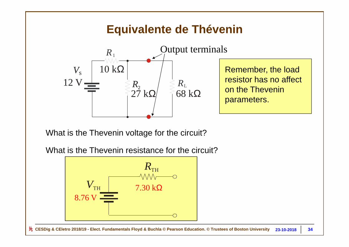
Equivalente de Thévenin
R
R
1
R2R2 L
VSVS
12 V10 kΩ
68 kΩ27 kΩ
Output terminals
What is the Thevenin voltage for the circuit?
What is the Thevenin resistance for the circuit?
Remember, the load resistor has no affect on the Theveninparameters.
VTH
RTH
8.76 V7.30 kΩ
34

CESDig & CEletro 2018/19 - Elect. Fundamentals Floyd & Buchla © Pearson Education. © Trustees of Boston Un iversityJF 30-10-201823-10-2018
Teorema de Thévenin
O teorema de Thévenin permite transformar um circuito complexo num circuito
bastante mais simples equivalente. Esta equivalência só é válida
relativamente aos terminais/porto em causa. Se for conside rado outro porto
do circuito as características ( VTH e RTH) do equivalente de Thévenin serão
diferentes.Exemplo:
CircuitooriginalVTH
R/ZTH
35

CESDig & CEletro 2018/19 - Elect. Fundamentals Floyd & Buchla © Pearson Education. © Trustees of Boston Un iversityJF 30-10-201823-10-2018
(R1+∆∆∆∆R1)
Se R1=R2=R3=R4 e ∆R1=0: VAB=0 V;
Ponte Wheatstone.
Exemplo de aplicação do teorema de Thévenin
Condição de balanceamento da ponte (quando VAB=0 V):
R1/R3=R2/R4
ou
R1R4=R2R3
Se R1=R3=R2=R4=R e ∆R1≠0:∆VAB= ∆R1(VS /4R)
36

CESDig & CEletro 2018/19 - Elect. Fundamentals Floyd & Buchla © Pearson Education. © Trustees of Boston Un iversityJF 30-10-201823-10-2018
Exemplo de aplicação do teorema de ThéveninDeterminação do equivalente de Thévenin da ponte de Wheatstone do porto AB.
V
Voltímetro/galvanómetro ou uma resistência RL
Cálculo da tensão de Thévenin:
37

CESDig & CEletro 2018/19 - Elect. Fundamentals Floyd & Buchla © Pearson Education. © Trustees of Boston Un iversityJF 30-10-201823-10-2018
Exemplo de aplicação do teorema de ThéveninDeterminação do equivalente de Thévenin da ponte de Wheatstone do porto AB.
Cálculo da resistência de Thévenin:Equivalente de Thévenin do porto AB:
38

CESDig & CEletro 2018/19 - Elect. Fundamentals Floyd & Buchla © Pearson Education. © Trustees of Boston Un iversityJF 30-10-201823-10-2018
Exemplo de aplicação do teorema de Thévenin
Thevenin’s theorem is useful for solving the Wheatstone bridge. One way
to Thevenize the bridge is to create two Thevenin circuits - from A to
ground and from B to ground.
The resistance between point A and
ground is R1||R3 and the resistance
from B to ground is R2||R4. The voltage
on each side of the bridge is found
using the voltage divider rule.
R3 R4
R2
RL
R1VS
-
+A B
Como determinar a corrente que percorre RL:
39

CESDig & CEletro 2018/19 - Elect. Fundamentals Floyd & Buchla © Pearson Education. © Trustees of Boston Un iversityJF 30-10-201823-10-2018
Exemplo de aplicação do teorema de Thévenin
For the bridge shown, R1||R3 = and R2||R4 = . The voltage from A to ground (with no load) is and from B to ground (with no load) is .
165 Ω179 Ω
7.5 V
6.87 VR3 R4
R2
RL
R1VS
-
+A B
330 Ω 390 Ω
330 Ω 330 Ω
+15 V150 Ω
A B
VTH VTH
RTH RTH'
'165 Ω 179 Ω
7.5 V 6.87 V
Como determinar a corrente que percorre RL:
40

CESDig & CEletro 2018/19 - Elect. Fundamentals Floyd & Buchla © Pearson Education. © Trustees of Boston Un iversityJF 30-10-201823-10-2018
Exemplo de aplicação do teorema de Thévenin
Putting the load on the Thévenin circuits and applying the superposition theorem allows you to calculate the load current.
RLA B
150 ΩVTH VTH
RTH RTH'
'165 Ω 179 Ω
7.5 V 6.87 V
A B
VTH VTH
RTH RTH'
'165 Ω 179 Ω
7.5 V 6.87 V
1.27 mAThe load current is:
Determinar a corrente que percorre RL:
41

CESDig & CEletro 2018/19 - Elect. Fundamentals Floyd & Buchla © Pearson Education. © Trustees of Boston Un iversityJF 30-10-201823-10-2018
Teorema de Norton
CESDig 2018/2019 4225-10-2018

CESDig & CEletro 2018/19 - Elect. Fundamentals Floyd & Buchla © Pearson Education. © Trustees of Boston Un iversityJF 30-10-201823-10-2018
A forma equivalente de Norton de qualquer circuito consiste numa fonte de corrente
(equivalente), IN, em paralelo com uma resistência/impedância (equivalente), R/ZN. A
corrente equivalente de Norton, IN, é a corrente em curto circuito (sem carga) entre os
dois pontos especificados (terminais) do circuito. A resistência/impedância equivalente de
Norton, R,ZN, é a resistência “vista” dos dois terminais especificados, e que se obtém, da
mesma forma que para o circuito equivalente de Thévenin, quando as fontes no circuito são
substituídas pelas respectivas resistências/impedâncias internas (zero no caso de fontes
ideais de tensão, e infinito no caso de fontes ideais de corrente).
Novamente, esta equivalência só é válida relativamente ao p orto em causa.
Teorema de Norton
IN
R/ZTH
4325-10-2018

CESDig & CEletro 2018/19 - Elect. Fundamentals Floyd & Buchla © Pearson Education. © Trustees of Boston Un iversityJF 30-10-201823-10-2018
Teorema da máxima transferida de potência para a carga
CESDig 2018/2019 4425-10-2018

CESDig & CEletro 2018/19 - Elect. Fundamentals Floyd & Buchla © Pearson Education. © Trustees of Boston Un iversityJF 30-10-201823-10-2018
Maximum power transfer
Qual é a potencia fornecida à carga de 30 Ω?
RS
RL
VS + 50 Ω
50 Ω10 V
30 Ω
RS
RL
VS + 50 Ω
50 Ω10 V
70 Ω
./ = //
= 0,37W
Qual é a potencia fornecida à carga de 70 Ω?
./ = //
= 0,49W
4525-10-2018

CESDig & CEletro 2018/19 - Elect. Fundamentals Floyd & Buchla © Pearson Education. © Trustees of Boston Un iversityJF 30-10-201823-10-2018
Maximum power transfer
The maximum power is transferred from a source to a load when the load resistance is equal to the internal source resistan ce. (The maximum power transfer theorem assumes the source voltage and resistance are fixed.)
RS
RL
VS +=RS
Qual é a potencia fornecida à carga de 50 Ω?
RS
RL
VS + 50 Ω
50 Ω10 V
50 Ω
./ = //
= 0,50W
Quando RS=RS, diz que a cargaestá adaptada à impedância dafonte, i.e., há adaptação deimpedâncias entre a carga e afonte.
4625-10-2018

CESDig & CEletro 2018/19 - Elect. Fundamentals Floyd & Buchla © Pearson Education. © Trustees of Boston Un iversityJF 30-10-201823-10-2018
Teorema da máxima transferências de potência da fonte para a carga
Seja uma fonte (ou circuito equivalente) caracterizada por VTH e RTH, à qual seliga uma carga RL. Seja a carga uma resistência variável RL (por exemplo umreóstato), ver figura. Qual o valor de RL que maximiza a potência transmitidapela fonte à carga?
P=V . I
PL=VL. IL=[RL/(RTH+RL)] VTH
. IL=[RL/(RTH+RL)2](VTH)2
Se RL=0, temos P=0 W; se RL=infinito, P=0 W.
O valor de PL é máximo quando d PL/dRL=0,
donde resulta RL=RTH, e:
PL max =(VTH)2/4RTH.
4725-10-2018

CESDig & CEletro 2018/19 - Elect. Fundamentals Floyd & Buchla © Pearson Education. © Trustees of Boston Un iversityJF 30-10-201823-10-2018
Exercícios(trabalho de casa)
4825-10-2018

CESDig & CEletro 2018/19 - Elect. Fundamentals Floyd & Buchla © Pearson Education. © Trustees of Boston Un iversityJF 30-10-201823-10-2018
Exercícios
3. For the circuit shown,
a. R1 is in series with R2
b. R1 is in parallel with R2
c. R2 is in series with R3
d. R2 is in parallel with R3
-
+
R1
R3
R2
VS
4. For the circuit shown,
a. R1 is in series with R2
b. R4 is in parallel with R1
c. R2 is in parallel with R3
d. none of the above -
+
R1
R4
R3
R2
VS
4925-10-2018

CESDig & CEletro 2018/19 - Elect. Fundamentals Floyd & Buchla © Pearson Education. © Trustees of Boston Un iversityJF 30-10-201823-10-2018
Exercícios
5. A signal generator has an output voltage of 2.0 V with no load. When a 600 W load is connected to it, the output drops to 1.0 V. The Thevenin resistance of the generator is
a. 300 W b. 600 W c. 900 W d. 1200 W.
6. For the circuit shown, Kirchhoff's voltage law
a. applies only to the outside loop
b. applies only to the A junction.
c. can be applied to any closed path.
d. does not apply.
R1
R3
470 Ω
270 Ω
R2
330 Ω
VS +10 V A
5025-10-2018

CESDig & CEletro 2018/19 - Elect. Fundamentals Floyd & Buchla © Pearson Education. © Trustees of Boston Un iversityJF 30-10-201823-10-2018
Exercícios7. The effect of changing a measured quantity due to connecting an instrument to a circuit is called
a. loading b. clipping c. distortion d. loss of precision
8. An unbalanced Wheatstone bridge has the voltages shown. The voltage across R4 is
a. 4.0 V
b. 5.0 V
c. 6.0 V
d. 7.0 V -
+
RL
R1R3
R4R2
VS
12 V
1.0 V
7.0 V+ -
5125-10-2018

CESDig & CEletro 2018/19 - Elect. Fundamentals Floyd & Buchla © Pearson Education. © Trustees of Boston Un iversityJF 30-10-201823-10-2018
Exercícios9. Assume R2 is adjusted until the Wheatstone bridge is balanced. At this point, the voltage across R4 is measured and found to be 5.0 V. The voltage across R1 will be
a. 4.0 V
b. 5.0 V
c. 6.0 V
d. 7.0 V
-
+
RL
R1R3
R4R2
VS
12 V
5.0 V
+ -
10. Maximum power is transferred from a fixed source when
a. the load resistor is ½ the source resistance
b. the load resistor is equal to the source resistance
c. the load resistor is twice the source resistance
d. none of the above
5225-10-2018

CESDig & CEletro 2018/19 - Elect. Fundamentals Floyd & Buchla © Pearson Education. © Trustees of Boston Un iversityJF 30-10-201823-10-2018
Circuitos Elétricos e Sistemas Digitais2018-2019 - 1.º Semestre
Fontes dependentes e teoremas de Thévenin e de Norto n
• Princípio da sobreposição
• Teorema de Thévenin
• Teorema de Norton
• Metodologias para aplicação do princípio da sobreposição
• Metodologia para determinação dos equivalentes de Thévevin e de Norte
• Exemplos de aplicação do princípio da sobreposição em circuitos com
fontes independentes e fontes dependentes
• Exemplos de determinação dos equivalentes de Thévevin e de Norte em
circuitos com fontes independentes e fontes dependentes
53CESDig 2018/2019 26-10-2018JF

CESDig & CEletro 2018/19 - Elect. Fundamentals Floyd & Buchla © Pearson Education. © Trustees of Boston Un iversityJF 30-10-201823-10-2018
Definição de porto
(Definition of a “Port”)
Port : Set of any two terminals
PORTO
PORTO
5426-10-2018

CESDig & CEletro 2018/19 - Elect. Fundamentals Floyd & Buchla © Pearson Education. © Trustees of Boston Un iversityJF 30-10-201823-10-2018
Simple resistive circuit
Vo
R1
R2vX
+
_
iX
Illustrate concept with a simple resistive circuit:
• Any two terminals can be designated as a port.
Define port variables vX and iX
• Our objective: Find the equivalent circuit seen looking into the port
ix flows to some load (not shown)
Definição de porto
(Definition of a “Port”)
5526-10-2018

CESDig & CEletro 2018/19 - Elect. Fundamentals Floyd & Buchla © Pearson Education. © Trustees of Boston Un iversityJF 30-10-201823-10-2018
When Thévenin’s/Norton’s Theorem is applied to circuits containing resistors, voltage sources, and/or current sources,
The circuit’s Thévenin Equivalent takes the form:
Circuitos equivalentes de Th évenin e de Norton
56
The circuit’s Norton Equivalent takes the form:
IN RNVTH
RTH
26-10-2018

CESDig & CEletro 2018/19 - Elect. Fundamentals Floyd & Buchla © Pearson Education. © Trustees of Boston Un iversityJF 30-10-201823-10-2018
Circuitos equivalentes de Th évenin e de NortonLéon Charles Thévenin (Meaux, 30 de março de 1857 – Paris, 21 de setembro de 1926) foi um engenheiro telegrafista francês que estendeu a Lei de Ohm à análise de circuitos elétricos complexos. Nomeado professor e inspetor da École Superieure em 1882, Thévenin tornou-se cada vez mais interessado em problemas de medidas em circuitos elétricos. Como resultado do estudo das Leis de Kirchhoff e da lei de Ohm, ele desenvolveu seu famoso teorema, o Teorema de Thévenin, que torna possível calcular correntes em circuitos elétricos complexos.M. Leon Thévenin (1857-1926), published his famous theorem in 1883.
Edward Lawry Norton (28 July 1898, Rockland, Maine – 28 January 1983, Chatham, New Jersey) was an accomplished Bell Labs engineer and scientist famous for Norton's theorem. He attended the University of Maine for two years before transferring to M.I.T.and received a S.B. degree (electrical engineering) in 1922. He received an M.A. degree from Columbia University in 1925. Although interested primarily in a communications circuit theory and the transmission of data at high speeds over telephone lines, E. L. Norton is best remembered for development of the dual of Thevenin's equivalent circuit, currently referred to as Norton's equivalent Circuit. In fact, Norton and his associates at AT&T in the early 1920s are recognized as some of the first to perform pioneering work applying Thevenin's equivalent circuit and who referred to this concept simply as Thévenin's theorem.
57
In 1926, he proposed the equivalent circuit using a current source and parallel resistor to assist in the design of recording instrumentation that was primarily current driven. He began his telephone career in 1922 with the western Electric Company's Engineering Department, which later became Bell Laboratories. His areas of active research included network theory, acoustical systems, electromagnetic apparatus, and data transmission. A graduate of MIT and Columbia University, he held nineteen patents on his work.
26-10-2018

CESDig & CEletro 2018/19 - Elect. Fundamentals Floyd & Buchla © Pearson Education. © Trustees of Boston Un iversityJF 30-10-201823-10-2018
Thévenin Equivalent Circuit
VTh
RTh
Thévenin’s Theorem: A resistive circuit can be represented by one voltage source and one resistor :
Resistive Circuit
Circuitos equivalentes de Th évenin e de Norton
O teorema de Thévenin pode ser generalizado para circuitos de corrente alternada sinusoidal:
Um circuito linear de corrente alternada pode ser representado por uma fonte de tensão sinusoidal em série com uma impedância.
5826-10-2018

CESDig & CEletro 2018/19 - Elect. Fundamentals Floyd & Buchla © Pearson Education. © Trustees of Boston Un iversityJF 30-10-201823-10-2018
Vo
R1
R2 vX
+
_
iX
Find an equation that relates vx to ix
i1
i2
KVL : i1R1 + i2R2 = Vo(Each resistor voltage expressed using Ohm’s Law)
Also note : vX = i2R2
KCL : i1 = i2 + iX
Circuitos equivalentes de Th évenin e de Norton
5926-10-2018

CESDig & CEletro 2018/19 - Elect. Fundamentals Floyd & Buchla © Pearson Education. © Trustees of Boston Un iversityJF 30-10-201823-10-2018
Solve these equations for vX versus iX :
i1R1 + i2R2 = Vo i1 = i X + i 2
RX = i 2R2(iX + i 2) R1 + i2R2 = Vo
(iX + vX/R2) R1 + vX = Vo
iX R1 + vX (R1 /R2 + 1) = Vo
Rearrange the variables…
orVo – iX R1vX = –––––––––1 + R1 /R2
R2 R1 R2vX = Vo ––––––– – iX –––––––R1 + R2 R1 + R2
Circuitos equivalentes de Th évenin e de Norton
6026-10-2018

CESDig & CEletro 2018/19 - Elect. Fundamentals Floyd & Buchla © Pearson Education. © Trustees of Boston Un iversityJF 30-10-201823-10-2018
R1 R2RTh = –––––––R1 + R2
R2 R1 R2vX = V0 ––––––– – iX –––––––R1 + R2 R1 + R2
V0
R1
R2 vX
+
_
iX
Examine this last equation:
It has the form vX = VTh – iX RTh
R2 VTh = V0 –––––––R1/ + R2
Circuitos equivalentes de Th évenin e de Norton
6126-10-2018

CESDig & CEletro 2018/19 - Elect. Fundamentals Floyd & Buchla © Pearson Education. © Trustees of Boston Un iversityJF 30-10-201823-10-2018
Vo
R1
R2
• Set all independent sources in the actual circuit to zero.
• For a voltage source, that means substituting a short circuit.
Equivalent resistance
• Equivalent resistance RTh= R1||R2
RTh is the equivalent resistance seen looking into the port with all independent sources set to zero.
Circuito equivalente de ThéveninEquivalent resistance
6226-10-2018

CESDig & CEletro 2018/19 - Elect. Fundamentals Floyd & Buchla © Pearson Education. © Trustees of Boston Un iversityJF 30-10-201823-10-2018
Circuito equivalente de Thévenin
VTh
RTh
vX
+
_
iX
Write down KVL for this circuit:
vX = VTh – iXRTh
+ –iXRTh
“Output voltage = voltage source – voltage drop acro ss RTh”
6326-10-2018

CESDig & CEletro 2018/19 - Elect. Fundamentals Floyd & Buchla © Pearson Education. © Trustees of Boston Un iversityJF 30-10-201823-10-2018
vX = VTh – iXRTh
VTh
RTh
vX
+
_
iX
Vo
R1
R2 vX
+
_
iX
R2 R1 R2vX = Vo ––––––– – iX –––––––R1 + R2 R1 + R2
Choose model parameters VTh and RTh:
Actual Circuit: Model:
R2 VTh = Vo –––––––R1 + R2
R1 R2RTh = ––––––= R1 || R2R1 + R2and
From the point of view of vX and iX, the Thévenin circuit models the actual circuit in every way.
Circuito equivalente de Thévenin
6426-10-2018

CESDig & CEletro 2018/19 - Elect. Fundamentals Floyd & Buchla © Pearson Education. © Trustees of Boston Un iversityJF 30-10-201823-10-2018
Vo
R1
R2
Actual Circuit:
R1 || R2
R2 Vo –––––––R1 + R2
PORT
PORT
vX
vX
iX
iX
+
_
+
_
Thévenin Equivalent:
Circuito equivalente de Thévenin
6526-10-2018

CESDig & CEletro 2018/19 - Elect. Fundamentals Floyd & Buchla © Pearson Education. © Trustees of Boston Un iversityJF 30-10-201823-10-2018
Significado de VTh
Vo
R1
R2
Open Circuit Voltage
• Connect nothing to the port
iX = 0
Open Circuit Voltage
• VTh represents the open circuit voltage of the actual circuit
iX = 0
• iX automatically set to zero.
• Port voltage is called the open circuit voltage.
+
_
VTh
RTh
+
_
+ 0 V –
KVL
6626-10-2018

CESDig & CEletro 2018/19 - Elect. Fundamentals Floyd & Buchla © Pearson Education. © Trustees of Boston Un iversityJF 30-10-201823-10-2018
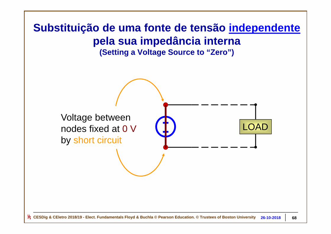
Substituição de uma fonte de tensão independentepela sua impedância interna
(Setting a Voltage Source to “Zero”)
Voltage betweennodes fixed at Vo
Current determined bywhat’s connected…
Vo
6726-10-2018
CESDig & CEletro 2018/19 - Elect. Fundamentals Floyd & Buchla © Pearson Education. © Trustees of Boston Un iversityJF 30-10-201823-10-2018
Voltage betweennodes fixed at 0 Vby short circuit
LOAD
68
Substituição de uma fonte de tensão independentepela sua impedância interna
(Setting a Voltage Source to “Zero”)
26-10-2018

CESDig & CEletro 2018/19 - Elect. Fundamentals Floyd & Buchla © Pearson Education. © Trustees of Boston Un iversityJF 30-10-201823-10-2018
Voltage betweennodes determined bywhat’s connected
Current through branch set to Io
Io
Substituição de uma fonte de corrente independente pela sua impedância interna
(Setting a Current Source to “Zero”)
6926-10-2018

CESDig & CEletro 2018/19 - Elect. Fundamentals Floyd & Buchla © Pearson Education. © Trustees of Boston Un iversityJF 30-10-201823-10-2018
Voltage betweennodes determined bywhat’s connected
Current through branch set to Io
Ioopen circuit
x
x
70
Substituição de uma fonte de corrente independente pela sua impedância interna
(Setting a Current Source to “Zero”)
26-10-2018

CESDig & CEletro 2018/19 - Elect. Fundamentals Floyd & Buchla © Pearson Education. © Trustees of Boston Un iversityJF 30-10-201823-10-2018
Equivalente de Thévenin do circuito representativo de um microfone
Balanced audio microphone system
R3 = 10 kΩR1=100 kΩ
R2 = 30 kΩ
R4 =10 kΩ
Vmic
10 mV
What voltage is developed across a 50 kΩ resistive load?
50 kΩ = Input resistance of typical audio amplifier
Microphone networkLoad
50 kΩ+
vLOAD
–
7126-10-2018

CESDig & CEletro 2018/19 - Elect. Fundamentals Floyd & Buchla © Pearson Education. © Trustees of Boston Un iversityJF 30-10-201823-10-2018
Background: How does a microphone or guitar pickup work?
Sound Wave
+voltage (replicates sound wave in time)–
+“vibrating” voltage–
Chargeddiaphragm
Vibration Typical output voltageabout 10 mV peak
What’s inside:
Como funciona um microfone?
7226-10-2018

CESDig & CEletro 2018/19 - Elect. Fundamentals Floyd & Buchla © Pearson Education. © Trustees of Boston Un iversityJF 30-10-201823-10-2018
Determinar o equivalente de Thévenin de um microfone
(Find the Thévenin Equivalent of the Microphone Network)
• Find Thevenin Equivalent of the remaining circuit.
• Reconnect the load.
• Find vLOAD from simplified circuit.
• Disconnect the load.
R1=100 kΩ
R2 = 30 kΩ
R3 = 10 kΩ
R4 =10 kΩ
Vmic
10 mV
Load Load
Find VThand RTh
7326-10-2018

CESDig & CEletro 2018/19 - Elect. Fundamentals Floyd & Buchla © Pearson Education. © Trustees of Boston Un iversityJF 30-10-201823-10-2018
Step 1: Find the Equivalent Resistance
• Set the voltage source to zero. (Substitute a short circuit.)
R1=100 kΩ
R2 = 30 kΩ
R3 = 10 kΩ
R4 =10 kΩ
RThVmic
• Find the equivalent resistance RTh
• RTh = R3 + R1||R2 + R4 = 10 kΩ + 23 kΩ + 10 kΩ = 43 kΩ
43 kΩ
RTh
Note: R1||R2 = (100 kΩ)||(30 kΩ) = 23 kΩ
Determinar o equivalente de Thévenin de um microfone
(Find the Thévenin Equivalent of the Microphone Network)
7426-10-2018

CESDig & CEletro 2018/19 - Elect. Fundamentals Floyd & Buchla © Pearson Education. © Trustees of Boston Un iversityJF 30-10-201823-10-2018
Step 2: Find the Open Circuit Voltage
• Analyze the circuit under no-load conditions.
R1=100 kΩ
R2 = 30 kΩ
R3 = 10 kΩ
R4 =10 kΩ
Vmic
10 mV
• Voltage across port terminals will be VTh
• From KVL around the inner loop*: v2 = VmicR2/(R1 + R2) = 2.3 mV
• Note that no current flows through R3 and R4.⇒ Voltage across these resistors is zero.
VTh = 2.3 mV
+
–
*basically, voltage division
Determinar o equivalente de Thévenin de um microfone
(Find the Thévenin Equivalent of the Microphone Network)
7526-10-2018

CESDig & CEletro 2018/19 - Elect. Fundamentals Floyd & Buchla © Pearson Education. © Trustees of Boston Un iversityJF 30-10-201823-10-2018
Step 3: Reconnect the Load to the Thévenin Equivalen t Model
RTh = 43 kΩ
VTh
2.3 mV
Thévenin equivalent ofmicrophone network
From simple voltage division:
vLOAD = VTh (RLOAD/(RLOAD + RTh)
= 2.3 mV × (50 kΩ)/(93 kΩ) = 0.54 mVAnswer
50 kΩ
+vLOAD
–RLOAD
Determinar o equivalente de Thévenin de um microfone
(Find the Thévenin Equivalent of the Microphone Network)
7626-10-2018

CESDig & CEletro 2018/19 - Elect. Fundamentals Floyd & Buchla © Pearson Education. © Trustees of Boston Un iversityJF 30-10-201823-10-2018 77
Circuito equivalente de Norton
IN RN
26-10-2018

CESDig & CEletro 2018/19 - Elect. Fundamentals Floyd & Buchla © Pearson Education. © Trustees of Boston Un iversityJF 30-10-201823-10-2018
Circuito equivalente de NortonCorrente de curto -circuito
One important parameter of a circuit is its short circuit current
The short circuit current of a port is defined as the current that will flow if:
The load is disconnected
A short circuit is connected instead
RTh
VTh Isc = VTh /RTh
7826-10-2018

CESDig & CEletro 2018/19 - Elect. Fundamentals Floyd & Buchla © Pearson Education. © Trustees of Boston Un iversityJF 30-10-201823-10-2018
Circuitos equivalentes de Norton e de Theveninde circuitos contendo fontes de corrente
Consider the following simple circuit:
I1 R1
What is the Thévenin equivalent circuit seen looking into the port?
Port
7926-10-2018

CESDig & CEletro 2018/19 - Elect. Fundamentals Floyd & Buchla © Pearson Education. © Trustees of Boston Un iversityJF 30-10-201823-10-2018
Step 1: Find the open circuit voltage :
I1 R1
+VTh
–
• From Ohm’s Law: VTh = I1R1
+
–
××××Current is zero
• Open circuit conditions ⇒ All of I1 flows through R1
• Voltage develops across R1 with polarity shown.
Circuito equivalente de circuitos contendo fontes de corrente independentes
8026-10-2018

CESDig & CEletro 2018/19 - Elect. Fundamentals Floyd & Buchla © Pearson Education. © Trustees of Boston Un iversityJF 30-10-201823-10-2018
Step 2: Find the equivalent resistance
I1 R1
• By inspection: RTh = R1
• Set the current source to zero.
• Find the resistance looking into the port.
RTh
• Set the current source to zero open circuit
Circuitos equivalentes de circuitos contendo fontes de corrente
8126-10-2018

CESDig & CEletro 2018/19 - Elect. Fundamentals Floyd & Buchla © Pearson Education. © Trustees of Boston Un iversityJF 30-10-201823-10-2018
The Thévenin Equivalent Circuit:
R1
I1R1
Thévenin Equivalent
VTh = I1R1
RTh = R1
Actual Circuit:
Done!
I1 R1
Circuitos equivalentes de circuitos contendo fontes de corrente independente
8226-10-2018

CESDig & CEletro 2018/19 - Elect. Fundamentals Floyd & Buchla © Pearson Education. © Trustees of Boston Un iversityJF 30-10-201823-10-2018
Norton Equivalent Circuit
• The Norton and Thévenin equivalents of a circuit are interchangeable.
• The equivalent resistance is the same: RN = RTh
• The open circuit voltage is the same: VTh = INRN
Norton Circuit .
RN
INRNIN RN
Thévenin Circuit .
Circuitos equivalentes de circuitos contendo fontes de corrente
8326-10-2018

CESDig & CEletro 2018/19 - Elect. Fundamentals Floyd & Buchla © Pearson Education. © Trustees of Boston Un iversityJF 30-10-201823-10-2018
IN RN Isc = IN
+VN = 0–
What about the short-circuit current from a Norton Circuit?
• Apply a short circuit:
• The voltage across the Norton resistance becomes zero.
• No current flows through the Norton resistance ( I = V/R).
• All the current flows through the short circuit.
• The short circuit current is the source current IN.
Norton Equivalent Circuit
Circuitos equivalentes de circuitos contendo fontes de corrente
8426-10-2018

CESDig & CEletro 2018/19 - Elect. Fundamentals Floyd & Buchla © Pearson Education. © Trustees of Boston Un iversityJF 30-10-201823-10-2018
Norton Equivalent Circuit
• The short circuit current is the same in each circuit: IN = VTh/RTh
Norton Circuit
VTh =
INRNIN =
VTh/RTh
RTh = RN
Thévenin Circuit
RN = RTh
IN IN
Circuitos equivalentes de circuitos contendo fontes de corrente independente
8526-10-2018

CESDig & CEletro 2018/19 - Elect. Fundamentals Floyd & Buchla © Pearson Education. © Trustees of Boston Un iversityJF 30-10-201823-10-2018
Equivalente de Norton do circuito representativo de um microfone
Balanced audio microphone system
R3 = 10 kΩR1=100 kΩ
R2 = 30 kΩ
R4 =10 kΩ
Vmic
10 mV
What voltage is developed across a 50 kΩ resistive load?
50 kΩ = Input resistance of typical audio amplifier
Microphone networkLoad
50 kΩ+
vLOAD
–
8626-10-2018

CESDig & CEletro 2018/19 - Elect. Fundamentals Floyd & Buchla © Pearson Education. © Trustees of Boston Un iversityJF 30-10-201823-10-2018
Equivalente de Norton do circuito representativo de um microfone
R1=100 kΩΩΩΩ
R2 = 30 kΩΩΩΩ
R3 = 10 kΩΩΩΩ
R4 =10 kΩΩΩΩ
Vmic
10 mV
Find the Norton Equivalent of the following circuit using the short-circuit current method:
87
Load
50 kΩ+
vLOAD
–
Equivalente de Norton
26-10-2018
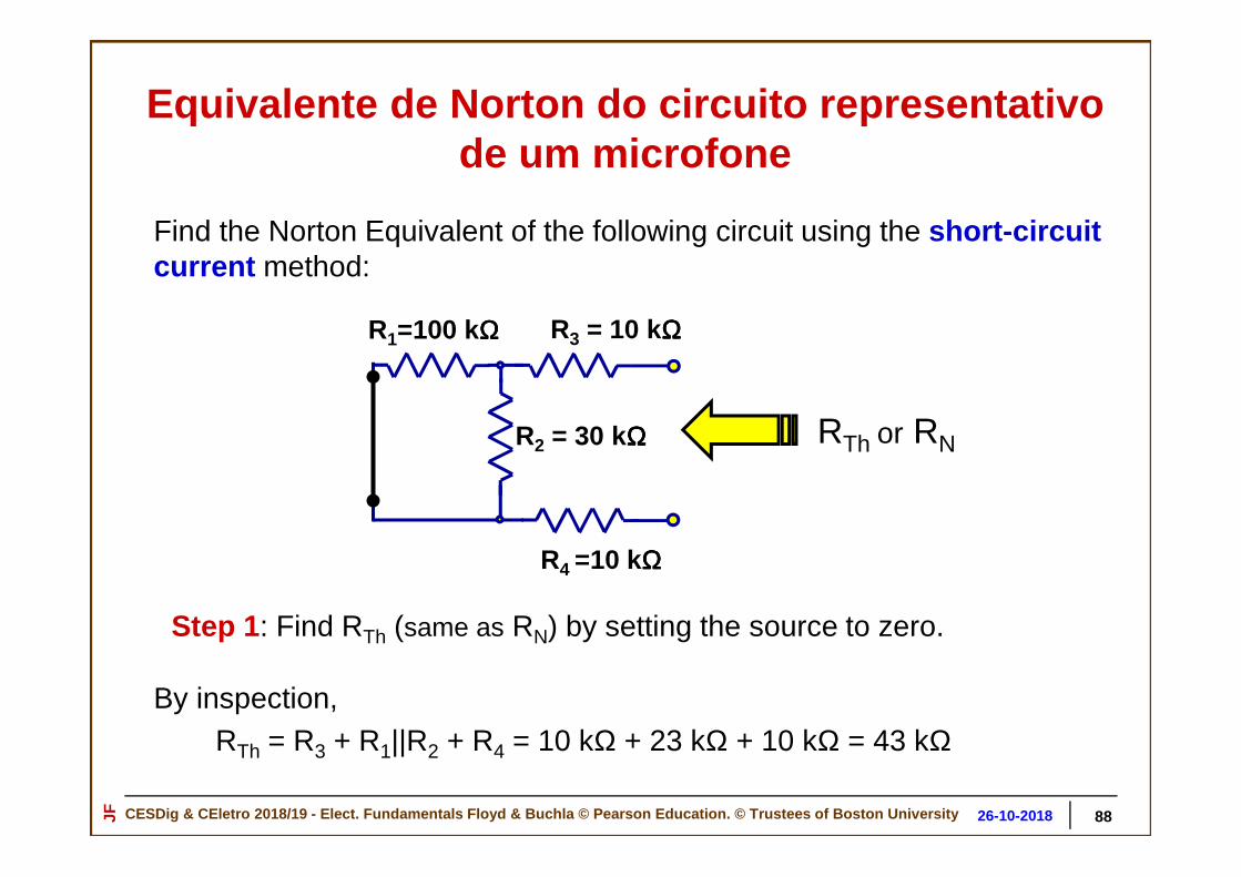
CESDig & CEletro 2018/19 - Elect. Fundamentals Floyd & Buchla © Pearson Education. © Trustees of Boston Un iversityJF 30-10-201823-10-2018
R1=100 kΩΩΩΩ
R2 = 30 kΩΩΩΩ
R3 = 10 kΩΩΩΩ
R4 =10 kΩΩΩΩ
Vmic
10 mV
Find the Norton Equivalent of the following circuit using the short-circuit current method:
Step 1 : Find RTh (same as RN) by setting the source to zero.
RTh or RN
By inspection,RTh = R3 + R1||R2 + R4 = 10 kΩ + 23 kΩ + 10 kΩ = 43 kΩ
88
Equivalente de Norton do circuito representativo de um microfone
26-10-2018

CESDig & CEletro 2018/19 - Elect. Fundamentals Floyd & Buchla © Pearson Education. © Trustees of Boston Un iversityJF 30-10-201823-10-2018
R2 = 30 kΩ
R3 = 10 kΩ
R4 =10 kΩ
R1=100 kΩ
Vmic
10 mV
Step 2 : Apply a short circuit to the port and compute the short-circuit current.
R1=100 kΩ
Vmic
10 mVRP = R2 || (R3 + R4) = 12 kΩ
IP = Vmic/(R1 + RP) = 0.9 µA
From current division:
R2
[R2 + (R3 + R4)]ISC = IP = 0.9 µA
30 kΩ50 kΩ = 0.54 µµµµA = ISC
= 0.54 µAISC
Equivalente de Norton do circuito representativo de um microfone
8926-10-2018

CESDig & CEletro 2018/19 - Elect. Fundamentals Floyd & Buchla © Pearson Education. © Trustees of Boston Un iversityJF 30-10-201823-10-2018
Find the Norton Equivalent of the Circuit
ISC = 0.54 µA
RN = 43 kΩ
RN = 43 kΩIN = 0.54 µA = 23 mV
+vOC
–
“Open Circuit Voltage”
vOC = IN RN = (0.54 µA)(43 kΩ) = 23 mV
9026-10-2018

CESDig & CEletro 2018/19 - Elect. Fundamentals Floyd & Buchla © Pearson Education. © Trustees of Boston Un iversityJF 30-10-201823-10-2018
Construct the Th évenin Equivalent of the Circuit
ISC = 0.54 µA RTh = 43 kΩ
VTh = ISC RTh = (0.54 µA )(43 kΩ) = 23 mV
VTh = 23 mV
RTh = 43 kΩ
This result is the same one obtained in the previous example.
9126-10-2018

CESDig & CEletro 2018/19 - Elect. Fundamentals Floyd & Buchla © Pearson Education. © Trustees of Boston Un iversityJF 30-10-201823-10-2018
A circuit that can be represented by a Thévenin Equivalent can also be represented by its corresponding Norton circuit
VTh= INRN
RTh = RN
IN RN
Norton Equivalent Thévenin Equivalent
RTh
VTh
Equivalence of Th évenin and Norton equivalents of the Circuit
9226-10-2018

CESDig & CEletro 2018/19 - Elect. Fundamentals Floyd & Buchla © Pearson Education. © Trustees of Boston Un iversityJF 30-10-201823-10-2018
Exemplos de aplicação do princípio da sobreposição
9326-10-2018

CESDig & CEletro 2018/19 - Elect. Fundamentals Floyd & Buchla © Pearson Education. © Trustees of Boston Un iversityJF 30-10-201823-10-2018
Princípio da sobreposição
94
Lets now find I3 using superposition principle
Premise:
• I3 has components contributed by each source in the network.
• We can solve for each of the components of I3 separately.
• The total I3 will be equal to the sum of the individual components.
Note: - Superposition only works on linear networks.- Resistive circuits fall into the class of linear networks.
(Remember that a resistive circuit may contain dependent sources)
26-10-2018
CESDig & CEletro 2018/19 - Elect. Fundamentals Floyd & Buchla © Pearson Education. © Trustees of Boston Un iversityJF 30-10-201823-10-2018
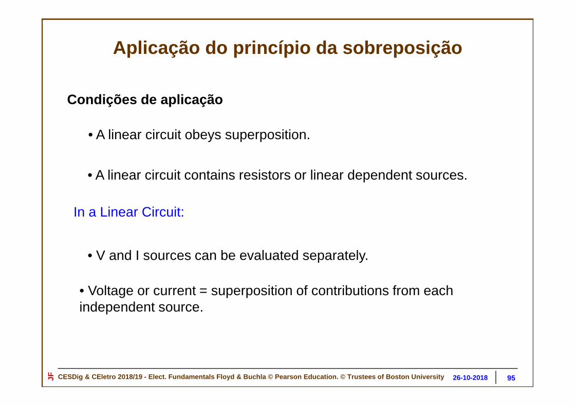
Aplicação do princípio da sobreposição
95
• A linear circuit obeys superposition.
• A linear circuit contains resistors or linear dependent sources.
• V and I sources can be evaluated separately.
In a Linear Circuit:
• Voltage or current = superposition of contributions from each independent source.
Condições de aplicação
26-10-2018
CESDig & CEletro 2018/19 - Elect. Fundamentals Floyd & Buchla © Pearson Education. © Trustees of Boston Un iversityJF 30-10-201823-10-2018
Princípio da sobreposição
96
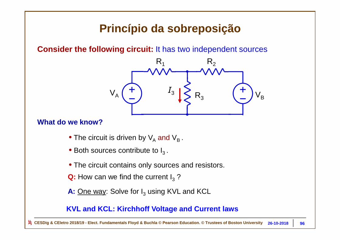
Consider the following circuit: It has two independent sources
VA VB
R1 R2
R3I3
• The circuit is driven by VA and VB .
• Both sources contribute to I3 .
Q: How can we find the current I3 ?
What do we know?
• The circuit contains only sources and resistors.
A: One way: Solve for I3 using KVL and KCL
KVL and KCL: Kirchhoff Voltage and Current laws
26-10-2018

CESDig & CEletro 2018/19 - Elect. Fundamentals Floyd & Buchla © Pearson Education. © Trustees of Boston Un iversityJF 30-10-201823-10-2018
Princípio da sobreposição
97
Let’s solve it first using KVL and KCL:
Find I3 using KVL and KCL
VA VB
R1 R2
R3I3
• Assign numbers to the remaining nodes
We can solve this circuit using the node and mesh method:
• Write down all KVL and KCL equations plus the voltage-current relation for each element in the network.
1 2 3
• Choose one node to be “ground”
26-10-2018

CESDig & CEletro 2018/19 - Elect. Fundamentals Floyd & Buchla © Pearson Education. © Trustees of Boston Un iversityJF 30-10-201823-10-2018
Princípio da sobreposição
98
• Write down KCL for node 2:
VA VB
R1 R2
R3
I3
1 2 3
I1 I2
BA• Write down KVL for loop A:
VA = I1 R1 + I3 R3
• Write down KVL for loop B:
VB = I2 R2 + I3 R3
I1 + I2 = I3
From Ohm’s Law:I1 = (VA − V2)/R1
I2 = (VB − V2)/R2
I3 = V2/R3
Example:
VA = I1 R1 + I3 R3
VB = I2 R2 + I3 R3
I3 = I1 + I2
I1 = (VA − v2)/R1
I2 = (VB − v2)/R2
I3 = v2/R3
The six equations summarized:
Exercise : Solve the above equations for I3.
Solving first using KVL and KCL
26-10-2018

CESDig & CEletro 2018/19 - Elect. Fundamentals Floyd & Buchla © Pearson Education. © Trustees of Boston Un iversityJF 30-10-201823-10-2018
Princípio da sobreposição
99
VAR1 + VB R2I3 =
R1R2 + R1R3 + R2R3
The Solution:
VAR1 + VB R2I3 =
R1R2 + R1R3 + R2R3
VA VB
R1 R2
R3
I3
• Notice that I3 has components of both VA and VB
Solving first using KVL and KCL
26-10-2018

CESDig & CEletro 2018/19 - Elect. Fundamentals Floyd & Buchla © Pearson Education. © Trustees of Boston Un iversityJF 30-10-201823-10-2018
Princípio da sobreposição
100
VA VB
R1 R2
R3
I3
Step 1 : Set VB to zero (short circuit) and solve for first component of I3.
VB = 0
I1
R2 VAR2I3 = I1 =
R2 + R3 R1R2 + R1R3 + R2R3
Component due to VA
• From Ohm’s Law:
VA VA VA (R2 + R3)I1 =
R1 + R2||R3 R1 + R2R3 R1R2 + R1R3 + R2R3
R2 + R3
= =
• By Current Division:
26-10-2018

CESDig & CEletro 2018/19 - Elect. Fundamentals Floyd & Buchla © Pearson Education. © Trustees of Boston Un iversityJF 30-10-201823-10-2018
Princípio da sobreposição
101
VA VB
R1 R2
R3
I3
Step 2 : Set VA to zero (short circuit) and solve for VB component of I3:
VA = 0
I
2
Component due to VB
VB VB (R1 + R3)Ohm’s Law: I2 = = R2 + R1||R3 R1R2 + R2R3 + R1R3
•
R1 VB R1Current Division: I3 = I2 = R1 + R3 R1R2 + R2R3 + R1R3
•
(Can evoke symmetry to use equations from last slide)
26-10-2018

CESDig & CEletro 2018/19 - Elect. Fundamentals Floyd & Buchla © Pearson Education. © Trustees of Boston Un iversityJF 30-10-201823-10-2018
Princípio da sobreposição
102
VA R2From VA: I3 = R1R2 + R1R3 + R2R3
VB R1From VB: I3 = R1R2 + R1R3 + R2R3
Total Current: I3 = R1R2 + R1R3 + R2R3
VA R2 + VB R1
• Superposition: I3 has components from both VA and VB
VAR1 + VB R2I3 =
R1R2 + R1R3 + R2R3
The Solution:VAR1 + VB R2
I3 = R1R2 + R1R3 + R2R3
VAR1 + VB R2I3 =
R1R2 + R1R3 + R2R3
The Solution:
Same
Answer!
26-10-2018

CESDig & CEletro 2018/19 - Elect. Fundamentals Floyd & Buchla © Pearson Education. © Trustees of Boston Un iversityJF 30-10-201823-10-2018
Aplicação do princípio da sobreposição
103
+_
R1 = 10 kΩ
R2 = 5 kΩI0
1.5 mAV0
6 V
X
X’
• Find the Thévenin Equivalent at X-X’ using Superposition
+
–
26-10-2018

CESDig & CEletro 2018/19 - Elect. Fundamentals Floyd & Buchla © Pearson Education. © Trustees of Boston Un iversityJF 30-10-201823-10-2018
Aplicação do princípio da sobreposição
104
+_
R1 = 10 kΩ
R2 = 5 kΩIo
1.5 mAVo
6 V
X
X’
Step 1: Find the Thévenin Resistance
Set sources to “zero”
• Voltage source short circuit
• Current source open circuit
RTh
RTh = R1 || R2 = = 3.33 kΩ(10 kΩ) (5 kΩ)
10 kΩ + 5 kΩ
26-10-2018

CESDig & CEletro 2018/19 - Elect. Fundamentals Floyd & Buchla © Pearson Education. © Trustees of Boston Un iversityJF 30-10-201823-10-2018
Aplicação do princípio da sobreposição
105
+_
R1 = 10 kΩ
R2 = 5 kΩIo
1.5 mAV0
6 V
X
X’
Step 2: Find component of open circuit voltage due to Vo
(Keep Io set to “zero”)
Voltage Division Applies to R1 and R2 :
VOC1
• Remember: Total VOC = Thévenin Voltage
Voc1 = = 6 V = 2 V 5 kΩ
10 kΩ + 5 kΩ
R2
R1 + R2
V0
+
–
26-10-2018

CESDig & CEletro 2018/19 - Elect. Fundamentals Floyd & Buchla © Pearson Education. © Trustees of Boston Un iversityJF 30-10-201823-10-2018
Aplicação do princípio da sobreposição
106
R1R2
R1 + R2
IoVoc2 = = (1.5 mA)(3.33 kΩ) = 5 V
+_
R1 = 10 kΩ
R2 = 5 kΩI0
1.5 mAVo
6 V
X
X’
Step 3: Find component of open circuit voltage due to Io
(Keep V0 set to “zero”)
Ohm's Law Applies to R1 || R2 :
VOC2
+
–
26-10-2018

CESDig & CEletro 2018/19 - Elect. Fundamentals Floyd & Buchla © Pearson Education. © Trustees of Boston Un iversityJF 30-10-201823-10-2018 107
Consistent with previous answer for VOC2
+_
R1 = 10 kΩ
R2 = 5 kΩI0
1.5 mAVo
6 V
X
X’
Step 3: Find component of open circuit voltage due to I0
(Alternate Method)
Use Current Division:
VOC2
Voc2 = = (1.5 mA)(3.33 kΩ) = 5 VR1R2
R1 + R2
I0
I2
R1
R1+ R2
I2 = I0
Use Ohm’s Law: VOC2 = I2R2
+
–
Aplicação do princípio da sobreposição
26-10-2018

CESDig & CEletro 2018/19 - Elect. Fundamentals Floyd & Buchla © Pearson Education. © Trustees of Boston Un iversityJF 30-10-201823-10-2018 108
+_
R1 = 10 kΩ
R2 = 5 kΩI0
1.5 mAV0
6 V
X
X’
Step 4: Find Total Thévenin Voltage:
(Turn on both V0 and I0 )
Superimpose VOC1 and VOC2 :
VTh
VTh =VOC1 + VOC2 = 2 V + 5 V = 7 V
+
–
Aplicação do princípio da sobreposição
26-10-2018

CESDig & CEletro 2018/19 - Elect. Fundamentals Floyd & Buchla © Pearson Education. © Trustees of Boston Un iversityJF 30-10-201823-10-2018 109
Step 5: Draw the Thévenin Equivalent Circuit:
+_VTh = 7 V
RTh = 3.33 kΩX
X’
+
–
Aplicação do princípio da sobreposição
26-10-2018

CESDig & CEletro 2018/19 - Elect. Fundamentals Floyd & Buchla © Pearson Education. © Trustees of Boston Un iversityJF 30-10-201823-10-2018
Aplicação do princípio da sobreposição
em circuitos com fontes dependentes
11026-10-2018

CESDig & CEletro 2018/19 - Elect. Fundamentals Floyd & Buchla © Pearson Education. © Trustees of Boston Un iversityJF 30-10-201823-10-2018
Condições de aplicação do princípio da sobreposição
Superposition cannot be used when:
The circuit is not linear
• Nonlinear –– ≠≠≠≠ constant vi
• Linear –– = constant vi
Resistor: –– = Rvi
+v–
iDiode
i = Is (e – 1) v / VT
exponential
11126-10-2018

CESDig & CEletro 2018/19 - Elect. Fundamentals Floyd & Buchla © Pearson Education. © Trustees of Boston Un iversityJF 30-10-201823-10-2018 112
Examples of linear elements:
Dependent Source –– = av2
v1
av1
+v2
–
Dependent Source –– = βi2v1
β v1
+i2–
Resistor: –– = Rvi
Fontes de tensão e de corrente dependentes lineares
26-10-2018

CESDig & CEletro 2018/19 - Elect. Fundamentals Floyd & Buchla © Pearson Education. © Trustees of Boston Un iversityJF 30-10-201823-10-2018
Princípio da sobreposição com fontes dependentes
113
iB
Strategy:Set v2 to zero; find component vOUT1
Set v1 to zero; find component vOUT2
Superimpose vOUT1 and vOUT2
Dependent source will contribute to vOUT1 and vOUT2
β iBRBRC
+_v2
vOUT
+
_+_v1
Do not set dependent source to zero
26-10-2018

CESDig & CEletro 2018/19 - Elect. Fundamentals Floyd & Buchla © Pearson Education. © Trustees of Boston Un iversityJF 30-10-201823-10-2018 114
Set v2 to "zero”; find component vOUT1
iB
β iBRB RC
+_v2
vOUT1
+
_+_v1
v2 = 0
iB = v1
RB
RC
RBvOUT1 = –β iB RC = – β v1
+v–
Princípio da sobreposição com fontes dependentes
26-10-2018

CESDig & CEletro 2018/19 - Elect. Fundamentals Floyd & Buchla © Pearson Education. © Trustees of Boston Un iversityJF 30-10-201823-10-2018 115
iB
β iBRBRC
+_v2
vOUT2
+
_
Superimpose vOUT1 and vOUT2
vOUT1 = –β v1RC
RB
vOUT2 = +β v2RC
RB
Princípio da sobreposição com fontes dependentes
26-10-2018

CESDig & CEletro 2018/19 - Elect. Fundamentals Floyd & Buchla © Pearson Education. © Trustees of Boston Un iversityJF 30-10-201823-10-2018 116
iB
β iBRBRC
+_v2
vOUT2
+
_+_v1
Superimpose vOUT1 and vOUT2
vOUT1 = –β v1RC
RB
vOUT2 = +β v2RC
RB
vOUT = vOUT1 + vOUT2 = β (v2 – v1)RC
RB
Princípio da sobreposição com fontes dependentes

CESDig & CEletro 2018/19 - Elect. Fundamentals Floyd & Buchla © Pearson Education. © Trustees of Boston Un iversityJF 30-10-201823-10-2018 117
Examples of nonlinear elements:
+v–
i
Diode i = Is (e – 1) v / VT
exponential
MOSFET (Metal-Oxide Semiconductor Field Effect Transistor)
+v–
i
i = K (v – VTR)2
square law
Elementos/componentes não -lineares

CESDig & CEletro 2018/19 - Elect. Fundamentals Floyd & Buchla © Pearson Education. © Trustees of Boston Un iversityJF 30-10-201823-10-2018
Elementos/componentes não -lineares
118
Example with Nonlinear Element:
MOSFET (Metal-Oxide Semiconductor Field Effect Transistor)
+v–
i
i = K (v – VTR)2
square law
vVTR
i

CESDig & CEletro 2018/19 - Elect. Fundamentals Floyd & Buchla © Pearson Education. © Trustees of Boston Un iversityJF 30-10-201823-10-2018
Elementos/componentes não -lineares
119
i = K (v – VTR)2
vVTR
i
+v–
i
+_
+_
V1
V23 V
5 V
K = 1 mA/V2
VTR = 2 V
MOSFET (Metal-Oxide Semiconductor Field Effect Transistor)

CESDig & CEletro 2018/19 - Elect. Fundamentals Floyd & Buchla © Pearson Education. © Trustees of Boston Un iversityJF 30-10-201823-10-2018 120
i = K (v – VTR)2
v2 V
i
+v–
i
+_
+_
V1
V23 V
5 V
K = 1 mA/V2
VTR = 2 V
5 V
i1 = (1 mA/V2 ) (5 V – 2 V)2 = 9 mA
9 mA
Elementos/componentes não -lineares
MOSFET (Metal-Oxide Semiconductor Field Effect Transistor)

CESDig & CEletro 2018/19 - Elect. Fundamentals Floyd & Buchla © Pearson Education. © Trustees of Boston Un iversityJF 30-10-201823-10-2018 121
i = K (v – VTR)2
v2 V
i
+v–
i
+_
+_
V1
V23 V
5 V
K = 1 mA/V2
VTR = 2 V
3 V
i2 = (1 mA/V2 ) (3 V – 2 V)2 = 1 mA
1 mA
i1 = (1 mA/V2 ) (5 V – 2 V)2 = 9 mA
Apparently, itot = i1 + i2 = 10 mA
Elementos/componentes não -lineares
MOSFET (Metal-Oxide Semiconductor Field Effect Transistor)

CESDig & CEletro 2018/19 - Elect. Fundamentals Floyd & Buchla © Pearson Education. © Trustees of Boston Un iversityJF 30-10-201823-10-2018 122
i = K (v – VTR)2
+v–
i
+_
+_
V1
V23 V
5 V
K = 1 mA/V2
VTR = 2 V
vVTR
i
8 V
36 mA
Apparently, itot = i1 + i2 = 10 mA
itot = (1 mA/V2 ) (8 V – 2 V)2 = 36 mA
Superposition
Elementos/componentes não -lineares
MOSFET (Metal-Oxide Semiconductor Field Effect Transistor)

CESDig & CEletro 2018/19 - Elect. Fundamentals Floyd & Buchla © Pearson Education. © Trustees of Boston Un iversityJF 30-10-201823-10-2018
Elementos/componentes não -lineares
The Bipolar Junction Transistor(BJT)
Base
Emitter
Collector
= + Do ponto de vista da corrente, o transístor bipolar (BJT) comporta-se como um nodo
Transístor bipolar npn
123

CESDig & CEletro 2018/19 - Elect. Fundamentals Floyd & Buchla © Pearson Education. © Trustees of Boston Un iversityJF 30-10-201823-10-2018
Condições de aplicação do princípio da sobreposição
124
• A linear circuit obeys superposition.
• A linear circuit contains resistors or linear dependent sources.
• V and I sources can be evaluated separately.
In a Linear Circuit:
• Voltage or current = superposition of contributions from each independent source.

CESDig & CEletro 2018/19 - Elect. Fundamentals Floyd & Buchla © Pearson Education. © Trustees of Boston Un iversityJF 30-10-201823-10-2018 125
Dependent Source –– = av2
v1
av1
+v2
–
Dependent Source –– = βi2v1
β v1
+i2–
Componentes não -lineares podem ser representados por fontes lineares dependentes
Em certas circunstâncias, numa dada gama de valores de corrente e tensão, um comportamento de componente linear pode ser caracterizado como sendo linear, e representado por uma fonte de tensão dependente ou uma fonte de corrente dependente.
CESDig & CEletro 2018/19 - Elect. Fundamentals Floyd & Buchla © Pearson Education. © Trustees of Boston Un iversityJF 30-10-201823-10-2018
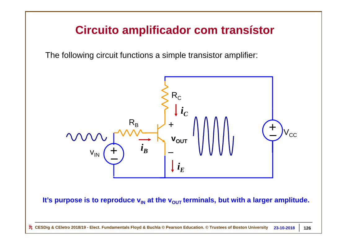
Circuito amplificador com transístor
The following circuit functions a simple transistor amplifier:
It’s purpose is to reproduce v IN at the vOUT terminals, but with a larger amplitude.
+_
+_RB
RC
vIN
vOUT
+
_
VCC
iC
iE
iB
126

CESDig & CEletro 2018/19 - Elect. Fundamentals Floyd & Buchla © Pearson Education. © Trustees of Boston Un iversityJF 30-10-201823-10-2018
• vIN is the input source to be amplified
Our Job : Find the relationship between VOUT and VIN when the transistor is represented by its linear model approximation.
+_
+_RB
RC
vIN
vOUT
+
_
VCC
(variable)
(fixed voltagesource)
• VCC is a fixed dc source that supplies raw power to the amplifier.
Circuito amplificador com transístor
127

CESDig & CEletro 2018/19 - Elect. Fundamentals Floyd & Buchla © Pearson Education. © Trustees of Boston Un iversityJF 30-10-201823-10-2018
Modelo linear de um Transístor npn
Base
Emitter
Collector
Device SymbolEquivalent Model
Rbe
iB
ββββ iB
B C
E
iC
iE
= + Do ponto de vista da corrente, o transístor bipolar (BJT) comporta-se como um nodo
Transístor bipolar npn
128

CESDig & CEletro 2018/19 - Elect. Fundamentals Floyd & Buchla © Pearson Education. © Trustees of Boston Un iversityJF 30-10-201823-10-2018
+_RB
RC
vIN
vOUT
+
_VCC
+_
Equivalent Model
Rbe
iB
β iB+_ +_
RB
RC
VCCvINvOUT
+
_
B
B
E
E
C
C
Circuito amplificador com transístor
129

CESDig & CEletro 2018/19 - Elect. Fundamentals Floyd & Buchla © Pearson Education. © Trustees of Boston Un iversityJF 30-10-201823-10-2018
Rbe
iB
β iB+_ +_
RBRC
VCCvINvOUT
+
_
Now solve the circuit:
First find iB using Kirchhoff’s Voltage Law and Ohm’s Law:
vIN = i B (RB + Rbe) (Voltage is independent of path taken)
vIN
vINiB = ————RB + Rbe
Circuito amplificador com transístor
130

CESDig & CEletro 2018/19 - Elect. Fundamentals Floyd & Buchla © Pearson Education. © Trustees of Boston Un iversityJF 30-10-201823-10-2018
Rbe
iB
β iB+_ +_
RB
RC
VCCvINvOUT
+
_
Next define a current iC
iC = β iB (Determined by properties of dependent source)
vIN
vINiB = ————RB + Rbe
iC
Circuito amplificador com transístor
131

CESDig & CEletro 2018/19 - Elect. Fundamentals Floyd & Buchla © Pearson Education. © Trustees of Boston Un iversityJF 30-10-201823-10-2018
Rbe
iB
β iB+_ +_
RB
RC
VCCvIN vOUT
+
_
Finally, use KVL to express vOUT in terms of iC:
iC = β iB
vIN
vINiB = ————RB + Rbe
iC
vOUT + iCRC = VCC
+_iCRC
(vOUT and the voltage across RC sum together)
vOUT = VCC – iCRC
KVL LOOP
Circuito amplificador com transístor
132

CESDig & CEletro 2018/19 - Elect. Fundamentals Floyd & Buchla © Pearson Education. © Trustees of Boston Un iversityJF 30-10-201823-10-2018
iC = β iBvINiB = ————
RB + RbevOUT = VCC – iCRC
Solve these equations:
β vINiC = ————RB + Rbe
vOUT = VCC –β RC———— vINRB + Rbe
This is the final result!
Circuito amplificador com transístor
133

CESDig & CEletro 2018/19 - Elect. Fundamentals Floyd & Buchla © Pearson Education. © Trustees of Boston Un iversityJF 30-10-201823-10-2018
Rbe
iB
β iB+_ +_
RB
RC
VCCvINvOUT
+
_
vOUT = VCC –β RC———— vINRB + Rbe
It multiplies vIN by Av and subtracts it from VCC
Amplification factor Av
What this circuit does:
Transistor Amplifier
Circuito amplificador com transístor
134

CESDig & CEletro 2018/19 - Elect. Fundamentals Floyd & Buchla © Pearson Education. © Trustees of Boston Un iversityJF 30-10-201823-10-2018
Circuito amplificador com transístor 2
• Find the gain A = ∆vOUT / ∆ vIN of the BJT circuit shown below, replacing the transistor by it linear model.
+_RB
RC
vINvOUT
+
_
VCC
+_RE
Base
Emitter
Collector
Linear Model
Rbe
iB
ββββ iB
B C
E
iC
iE135

CESDig & CEletro 2018/19 - Elect. Fundamentals Floyd & Buchla © Pearson Education. © Trustees of Boston Un iversityJF 30-10-201823-10-2018
Circuito amplificador MOSFET
+_
+_
RS
vIN vOUT
+
_
VD
Transístor MOSFET
136

CESDig & CEletro 2018/19 - Elect. Fundamentals Floyd & Buchla © Pearson Education. © Trustees of Boston Un iversityJF 30-10-201823-10-2018
Equivalent ModelMOSFET
+vg
–gmvg
Modelo do MOSFET
137

CESDig & CEletro 2018/19 - Elect. Fundamentals Floyd & Buchla © Pearson Education. © Trustees of Boston Un iversityJF 30-10-201823-10-2018
gmvg+_ +_ VDvIN
vOUT
+
_
+vg
–
= gmvgRSRS
vIN = vg + vOUT = vg + gmvgRS
vg = vIN / (1 + gmRS)
vOUT = gmRSvgvOUT = vIN [gmRS / (1 + gmRS)]
Modelo do amplificador MOSFET
138

CESDig & CEletro 2018/19 - Elect. Fundamentals Floyd & Buchla © Pearson Education. © Trustees of Boston Un iversityJF 30-10-201823-10-2018
This circuit is a model for a guitar amplifier system:
• Multiply vmic by a large number• Apply as “amplified” voltage to loudspeaker• Sound comes out
+_Avv1
ROUT
RIN
+v1–
GuitarPickup
Loud-speaker
Box 1 Box 2
+vmic–
Rmic
Circuito amplificador áudio
139

CESDig & CEletro 2018/19 - Elect. Fundamentals Floyd & Buchla © Pearson Education. © Trustees of Boston Un iversityJF 30-10-201823-10-2018
Background: How does a microphone or guitar pickup work?
Sound Wave
+voltage (replicates sound wave in time)–
+“vibrating” voltage–
Chargeddiaphragm
Vibration Typical output voltageabout 10 mV peak
What’s inside:
Como funciona um microfone?
140

CESDig & CEletro 2018/19 - Elect. Fundamentals Floyd & Buchla © Pearson Education. © Trustees of Boston Un iversityJF 30-10-201823-10-2018
Stationary magnet
How does a loudspeaker work?
Sound WaveS N
Diaphragm
Coil
Typical loudspeaker: An 8-ΩΩΩΩ resistor
“Audio” voltage
Como funciona um altifalante
141

CESDig & CEletro 2018/19 - Elect. Fundamentals Floyd & Buchla © Pearson Education. © Trustees of Boston Un iversityJF 30-10-201823-10-2018
Question: Determine the value of Av if the amplifier must deliver 10 W of power to the loudspeaker.
+_Avv1
ROUT
RIN
+v1–
GuitarPickup
Loud-speaker
Box 1 Box 2
+vmic–
Rmic
Parameters: Rmic = 10 kΩ RIN = 10 kΩ ROUT = 2 Ω
Exercício: determinar o ganho do amplificador áudio
142

CESDig & CEletro 2018/19 - Elect. Fundamentals Floyd & Buchla © Pearson Education. © Trustees of Boston Un iversityJF 30-10-201823-10-2018
+_Avv1
ROUT
RIN
+v1–
GuitarPickup
Loud-speaker
Box 1 Box 2
+vmic–
Rmic
Original circuit:
Model of the circuit:
Box 1 Box 2
RIN10 k ΩΩΩΩ
+v1–
vmic10 mV
Rmic = 10 k ΩΩΩΩ
+_Avv1
ROUT = 2 ΩΩΩΩ
Rload= 8 Ω
? 10 W
Exercício: determinar o ganho do amplificador áudio

CESDig & CEletro 2018/19 - Elect. Fundamentals Floyd & Buchla © Pearson Education. © Trustees of Boston Un iversityJF 30-10-201823-10-2018
Rload8 Ω
• Find v1 using voltage division :
RIN 10 kΩv1 = vmic ———— = 10 mV ————— = 5 mV
Rmic + RIN 10 kΩ + 10 kΩ
This voltage is transferred to the dependent source as Avv1
• Find vload using voltage division :
Rload 8 Ωvload = Avv1 ———— = Avv1 ————— = 0.8 Av (5 mV)
ROUT + Rload 2 Ω + 8 kΩ
RIN+v1–
vmic10 mV
Rmic
+_Avv1
ROUT
10 kΩ
10 kΩ
2 Ω+
vload–
Solvenothing herenothing here
Exercício: determinar o ganho do amplificador áudio

CESDig & CEletro 2018/19 - Elect. Fundamentals Floyd & Buchla © Pearson Education. © Trustees of Boston Un iversityJF 30-10-201823-10-2018
vload = 0.8 Av (5 mV) = 4 Av mV
RIN+v1–
vmic10 mV
Rmic
+_Avv1
ROUT
10 kΩ
10 kΩ
2 Ω+
vload–
• Find the power into the loudspeaker load:Pload = vload iload = (vload)2 /Rload
Rload8 Ω
• Finally, compute the Av required if Pload = 10 W:
= (4 mV)2 Av2 /(8 Ω) = 2×10⁻⁶ Av
2
Av = √ Pload (2×10⁻⁶) = √(10 W)/(2×10–6) ≈ 2240
Exercício: determinar o ganho do amplificador áudio

CESDig & CEletro 2018/19 - Elect. Fundamentals Floyd & Buchla © Pearson Education. © Trustees of Boston Un iversityJF 30-10-201823-10-2018 146
Equivalente de Thévenin de circuitos com fontes dependentes

CESDig & CEletro 2018/19 - Elect. Fundamentals Floyd & Buchla © Pearson Education. © Trustees of Boston Un iversityJF 30-10-201823-10-2018
Equivalente de Thévenin de circuitos com fontes independentes
Up until now … there were resistors and independent sources only
+_ Port
Resistors and Independent Sources Only
147

CESDig & CEletro 2018/19 - Elect. Fundamentals Floyd & Buchla © Pearson Education. © Trustees of Boston Un iversityJF 30-10-201823-10-2018
Determinar o equivalente de Thévenin de circuitos com fontes independentes
• Find Open Circuit Voltage VTh
+_ VTh
148
• Set sources to zero
RTh
• Find net resistance RTh seen at the port
+_

CESDig & CEletro 2018/19 - Elect. Fundamentals Floyd & Buchla © Pearson Education. © Trustees of Boston Un iversityJF 30-10-201823-10-2018
Qual o procedimento quando existem fontes dependentes no circuito?
iB
β iB
+_RB
v1
RE Port
Do NOT set to zero
Example
149
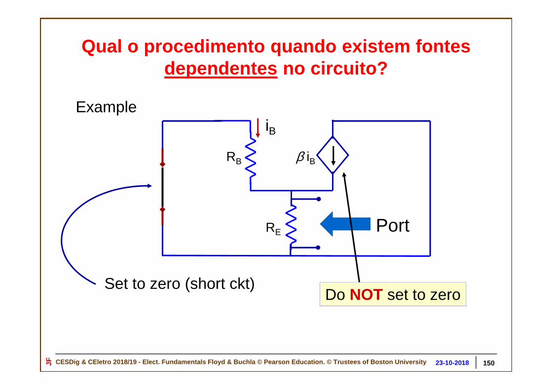
CESDig & CEletro 2018/19 - Elect. Fundamentals Floyd & Buchla © Pearson Education. © Trustees of Boston Un iversityJF 30-10-201823-10-2018
Qual o procedimento quando existem fontes dependentes no circuito?
iB
β iB
+_RB
v1
RE Port
Set to zero (short ckt)Do NOT set to zero
Example
150

CESDig & CEletro 2018/19 - Elect. Fundamentals Floyd & Buchla © Pearson Education. © Trustees of Boston Un iversityJF 30-10-201823-10-2018
VTh
Rationale:
+_ +_ Vtest
ItestRTh Vtest
RTh=
Test source
151
Dependent Source: Must Use “Test Source” Method to find RTh
Equivalente de Thevenin de circuitos com fontes dependentes
Set to zero (short ckt)

CESDig & CEletro 2018/19 - Elect. Fundamentals Floyd & Buchla © Pearson Education. © Trustees of Boston Un iversityJF 30-10-201823-10-2018
In the Test Source method:Vtest
Itest
=RTh
= Vtest / RTh
Method A
RThMethod B Itest
+
_
Vtest = Itest RTh
+_ Vtest
RTh
Itest
152
Equivalente de Thevenin de circuitos com fontes dependentes

CESDig & CEletro 2018/19 - Elect. Fundamentals Floyd & Buchla © Pearson Education. © Trustees of Boston Un iversityJF 30-10-201823-10-2018
iB
β iB
+_RB
v1
RE
Circuit with one independent source and one dependent source
153
Equivalente de Th évenin de circuitos com fontes dependentes
Port

CESDig & CEletro 2018/19 - Elect. Fundamentals Floyd & Buchla © Pearson Education. © Trustees of Boston Un iversityJF 30-10-201823-10-2018
+_ Vtest
iB
β iB
+_RB
v1
RE
Circuit with independent source set to zero
Itest = ?
• Solve the circuit for Itest
• Compute Vtest /Itest to find RTh
154
Equivalente de Thevenin de circuitos com fontes dependentes
Dependent Source: Must Use “Test Source” Method to find RTh

CESDig & CEletro 2018/19 - Elect. Fundamentals Floyd & Buchla © Pearson Education. © Trustees of Boston Un iversityJF 30-10-201823-10-2018
iB
β iB
+_RB
v1
RE
Apply KVL:
+_ Vtest
Itest = ?
Vtest
+
_
Vtest
+
_
Vtest RB
–iB =
155
Equivalente de Thevenin de circuitos com fontes dependentes
Dependent Source: Must Use “Test Source” Method to find RTh
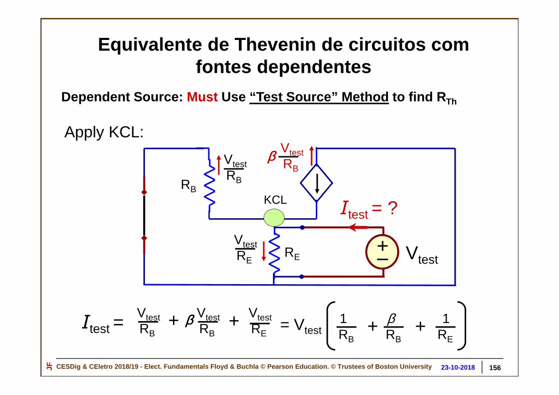
CESDig & CEletro 2018/19 - Elect. Fundamentals Floyd & Buchla © Pearson Education. © Trustees of Boston Un iversityJF 30-10-201823-10-2018
+_RB
RE+_ Vtest
Itest = ?
VtestRB
VtestRB
ββββ
Apply KCL:
KCL
Itest = Vtest RB
Vtest RB
ββββ+ Vtest RE
+
Vtest RE
1RB
βRB
+ 1RE
+= Vtest
156
Equivalente de Thevenin de circuitos com fontes dependentes
Dependent Source: Must Use “Test Source” Method to find RTh

CESDig & CEletro 2018/19 - Elect. Fundamentals Floyd & Buchla © Pearson Education. © Trustees of Boston Un iversityJF 30-10-201823-10-2018
Solve for RTh = Vtes t/Itest
+_RB
RE+_ Vtest
Itest
Vtest RB
Vtest RB
β
Vtest RE
Itest = 1RB
βRB
+1
RE+Vtest
Itest
1RB
βRB
+1
RE+
Vtest =
157
Equivalente de Th évenin de circuitos com fontes dependentes
Dependent Source: Must Use “Test Source” Method to find RTh
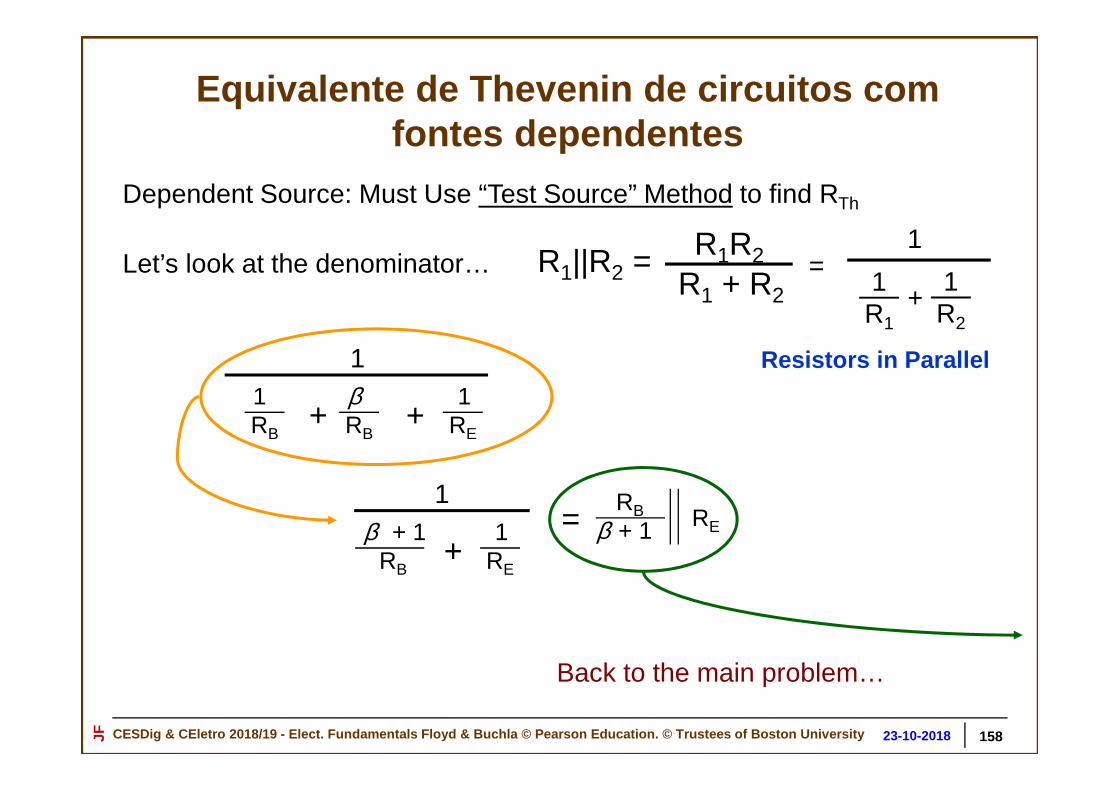
CESDig & CEletro 2018/19 - Elect. Fundamentals Floyd & Buchla © Pearson Education. © Trustees of Boston Un iversityJF 30-10-201823-10-2018
1RB
βRB
+1
RE+
1
Let’s look at the denominator…
1RE
β + 1RB
+
1RE
RBβ + 1=
Back to the main problem…
Resistors in Parallel
R1||R2 = R1R2
R1 + R2=
1R1
1R2
+
1
158
Equivalente de Thevenin de circuitos com fontes dependentes
Dependent Source: Must Use “Test Source” Method to find RTh

CESDig & CEletro 2018/19 - Elect. Fundamentals Floyd & Buchla © Pearson Education. © Trustees of Boston Un iversityJF 30-10-201823-10-2018
Solve for RTh = Vtest/Itest
+_RB
RE+_ Vtest
Itest
Vtest RB
Vtest RB
β
Vtest RE
Itest
1RB
βRB
+1
RE+
Vtest = = ItestRE
RBβ + 1
=Vtest
ItestRE
RBβ + 1RTh =
159
Equivalente de Thevenin de circuitos com fontes dependentes

CESDig & CEletro 2018/19 - Elect. Fundamentals Floyd & Buchla © Pearson Education. © Trustees of Boston Un iversityJF 30-10-201823-10-2018
What happens if we erroneously set Dependent Source to zero?
+_RB
RE+_ Vtest
Itest
Vtest RB
Vtest RE
=Vtest
ItestRERBRTh =
Wrong!
But why?
160
Equivalente de Thévenin de circuitos com fontes dependentes

CESDig & CEletro 2018/19 - Elect. Fundamentals Floyd & Buchla © Pearson Education. © Trustees of Boston Un iversityJF 30-10-201823-10-2018
+_RB
RE+_ Vtest
Itest
Vtest RB
Vtest RE
Vtest
+
_
β iB
• Vtest sets the voltage across RB
• Vtest across RB sets the value of iB
• iB sets the value of the dependent source
161
Equivalente de Thevenin de circuitos com fontes dependentes
But why?

CESDig & CEletro 2018/19 - Elect. Fundamentals Floyd & Buchla © Pearson Education. © Trustees of Boston Un iversityJF 30-10-201823-10-2018
iB
β iBRB
RE
+_ V1
RC
Another Example: Find the Thévenin Equivalent Resistance of this circuit
Port
162
Equivalente de Thévenin de circuitos com fontes dependentes

CESDig & CEletro 2018/19 - Elect. Fundamentals Floyd & Buchla © Pearson Education. © Trustees of Boston Un iversityJF 30-10-201823-10-2018
iB
β iBRB
RE
+_ V1
RC
Another Example: Find the Thévenin Equivalent Resistance of this circuit
• Set the independent source to zero
• Apply a test current source
PortItest
163
Equivalente de Thévenin de circuitos com fontes dependentes

CESDig & CEletro 2018/19 - Elect. Fundamentals Floyd & Buchla © Pearson Education. © Trustees of Boston Un iversityJF 30-10-201823-10-2018
iB = Itest
β iBRB
RE
RC
Itest
Itest+β Itest
+ItestRB
–
+ItestRE
–(β+1)
+Vtest = Itest RB + (β+1)RE
–
=Vtest
Itest
RB + (β + 1)RERTh = Done!
164
Equivalente de Thévenin de circuitos com fontes dependentes

CESDig & CEletro 2018/19 - Elect. Fundamentals Floyd & Buchla © Pearson Education. © Trustees of Boston Un iversityJF 30-10-201823-10-2018
vin+v1
–
A v1Loudspeakerload
Volume ControlDependent Source
Amplifier Volume Control
165
Equivalente de Thévenin de circuitos com fontes dependentes
Potenciómetro

CESDig & CEletro 2018/19 - Elect. Fundamentals Floyd & Buchla © Pearson Education. © Trustees of Boston Un iversityJF 30-10-201823-10-2018
+_VBB
vs
RB
RC
+
_vOUTinput
Output
+VCC
–B
C
E
Transistor Amplifier
Equivalente de Thévenin de circuitos com fontes dependentes
166

CESDig & CEletro 2018/19 - Elect. Fundamentals Floyd & Buchla © Pearson Education. © Trustees of Boston Un iversityJF 30-10-201823-10-2018 167
Substitute the transistor model:
RC
+
_VOUT
RB
+_VBB
Vin
Dependent Source
+VCC
–
Rp
β iB
iB BC
Equivalente de Thévenin de circuitos com fontes dependentes
E

CESDig & CEletro 2018/19 - Elect. Fundamentals Floyd & Buchla © Pearson Education. © Trustees of Boston Un iversityJF 30-10-201823-10-2018
Find iB: RC
+
_VOUT
RB
+_VBB
vs
Dependent Source
Rpβ iB
iB
KVL: VBB + vs = iB (RB + Rp) RB + Rp
VBB + vsiB =
We know iB Find vOUT
KVL
+VCC
–
Equivalente de Thévenin de circuitos com fontes dependentes
168

CESDig & CEletro 2018/19 - Elect. Fundamentals Floyd & Buchla © Pearson Education. © Trustees of Boston Un iversityJF 30-10-201823-10-2018
RB + Rp
VBB + vsiB = RC
RB
+_VBB
vs Rpβ iB
iB +
_vOUT
+VCC
–
KVL: VCC = β iBRC + vOUT
+
_β iB RC
vOUT = VCC – β iBRC
= VCC – β RC
RB + Rp
(VBB + vs)vOUT
Gain Factor
KVL
Equivalente de Thévenin de circuitos com fontes dependentes
169

CESDig & CEletro 2018/19 - Elect. Fundamentals Floyd & Buchla © Pearson Education. © Trustees of Boston Un iversityJF 30-10-201823-10-2018
vs
vOUT
VCC
β RC
RB + Rp
(VBB + vs)vOUT
Gain Factor
VCC –RB + Rp
β RC
VBB Slope = –β RC /(RB + Rp)
Equivalente de Thévenin de circuitos com fontes dependentes
= VCC –
170

CESDig & CEletro 2018/19 - Elect. Fundamentals Floyd & Buchla © Pearson Education. © Trustees of Boston Un iversityJF 30-10-201823-10-2018
+_VBB
vs
RB
RC
RE
+
_vOUTinput
output
+VCC
–
Transistor Amplifier II
C
E
B
171
Equivalente de Thévenin de circuitos com fontes dependentes

CESDig & CEletro 2018/19 - Elect. Fundamentals Floyd & Buchla © Pearson Education. © Trustees of Boston Un iversityJF 30-10-201823-10-2018
Substitute the transistor model:
RE
RC
+
_vOUT
RB
+_VBB
vs
Dependent source
Rp β iB
iB
+VCC
–
Equivalente de Thévenin de circuitos com fontes dependentes
No exemplo anterior RE era 0 Ω
172
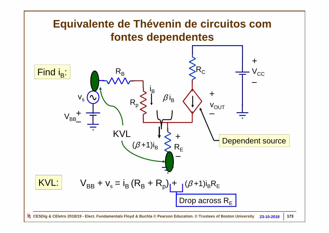
CESDig & CEletro 2018/19 - Elect. Fundamentals Floyd & Buchla © Pearson Education. © Trustees of Boston Un iversityJF 30-10-201823-10-2018 173
Find iB:
RE
RC
+
_vOUT
RB
+_VBB
vs
Dependent source
Rpβ iB
iB
KVL
KVL: VBB + vs = iB (RB + Rp) + (β +1)iBRE
Drop across RE
(β +1)iB+
_
+VCC
–
Equivalente de Thévenin de circuitos com fontes dependentes

CESDig & CEletro 2018/19 - Elect. Fundamentals Floyd & Buchla © Pearson Education. © Trustees of Boston Un iversityJF 30-10-201823-10-2018
VBB + vs = iB(RB + Rp) + (β +1)iBRE RB + Rp + (β +1)RE
VBB + vsiB =
We know iB Find vOUT
RCRB
+_VBB
vs
RE
Rpβ iB
iB +
_vOUT
+VCC
–
Equivalente de Thévenin de circuitos com fontes dependentes
174
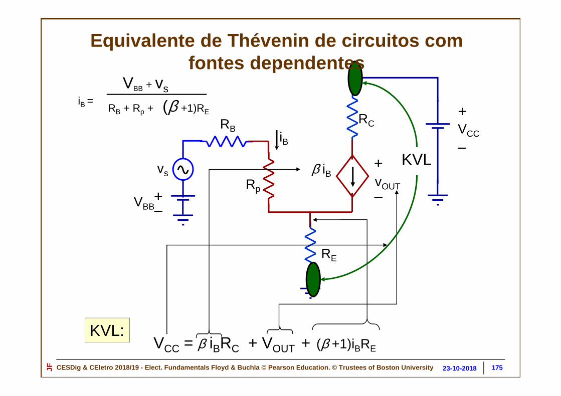
CESDig & CEletro 2018/19 - Elect. Fundamentals Floyd & Buchla © Pearson Education. © Trustees of Boston Un iversityJF 30-10-201823-10-2018
RB + Rp + (β +1)RE
VBB + vsiB =
RCRB
+_VBB
vs
RE
Rp
β iB
iB
+
_vOUT
KVL
+VCC
–
KVL:VCC = β iBRC + VOUT + (β +1)iBRE
Equivalente de Thévenin de circuitos com fontes dependentes
175

CESDig & CEletro 2018/19 - Elect. Fundamentals Floyd & Buchla © Pearson Education. © Trustees of Boston Un iversityJF 30-10-201823-10-2018
VCC = β iBRC + VOUT + (β +1)iBRE
Solve for vOUT
vOUT = VCC – [ β iBRC + (β +1)iBRE ]
= VCC – iB [β RC + (β +1)RE ]
vOUT = VCC – (VBB + vs) RB + Rp + (β +1)RE
β RC + (β +1)RE
Gain Factor
(from output loop)RB + Rp + (β +1)RE
VBB + vsiB =
(from input loop)
Equivalente de Thévenin de circuitos com fontes dependentes
176

CESDig & CEletro 2018/19 - Elect. Fundamentals Floyd & Buchla © Pearson Education. © Trustees of Boston Un iversityJF 30-10-201823-10-2018
Nota suplementar sobre o potenciómetro
17726-10-2018

CESDig & CEletro 2018/19 - Elect. Fundamentals Floyd & Buchla © Pearson Education. © Trustees of Boston Un iversityJF 30-10-201823-10-2018
Resistências variáveispotenciómetros e reóstatos
17826-10-2018

CESDig & CEletro 2018/19 - Elect. Fundamentals Floyd & Buchla © Pearson Education. © Trustees of Boston Un iversityJF 30-10-201823-10-2018
1 2 3
1
2
3
Como funciona um potenciómetro? How it works….
10 kΩ
1 2 3
Thin film of resistive material
17926-10-2018

CESDig & CEletro 2018/19 - Elect. Fundamentals Floyd & Buchla © Pearson Education. © Trustees of Boston Un iversityJF 30-10-201823-10-2018
1 2 3
Divisor de tensão resistivo usando um potenciómetroResistive Voltage Divider
1 2 3
1 3 RTOT1 3 RTOT
2
RAA
BRB
RTOT
18026-10-2018

CESDig & CEletro 2018/19 - Elect. Fundamentals Floyd & Buchla © Pearson Education. © Trustees of Boston Un iversityJF 30-10-201823-10-2018
1 2 3
αααα
RA RB
RA = RTOTθαααα
RB = RTOT
(αααα − θ)αααα
RA
RB
1 3
αααα
θθθθRTOT
2
θθθθ
Divisor de tensão resistivo usando um potenciómetroResistive Voltage Divider
18126-10-2018

CESDig & CEletro 2018/19 - Elect. Fundamentals Floyd & Buchla © Pearson Education. © Trustees of Boston Un iversityJF 30-10-201823-10-2018
+_V0
αααα θθθθvout = (θθθθ/αααα)V0
vout= V0 = Vo
RA
RA + RB
RA
RTOTvout = V0
θαααα
RA
RB
Divisor de tensão usando um potenciómetro
18226-10-2018

CESDig & CEletro 2018/19 - Elect. Fundamentals Floyd & Buchla © Pearson Education. © Trustees of Boston Un iversityJF 30-10-201823-10-2018
1 3x
2
+_V0
Vout(x) + Function of x
1 2 3
x
Machine tool
Moving bed
Exemplo de aplicação do potenciómetro – sensor de po sição
18326-10-2018

CESDig & CEletro 2018/19 - Elect. Fundamentals Floyd & Buchla © Pearson Education. © Trustees of Boston Un iversityJF 30-10-201823-10-2018
Outros tipos de resistências variávelOther Types of Variable Resistors
Ten Turn PotentiometersVariable Power ResistorVariable Power ResistorVariable Power Resistor(rheostat / reóstato)
Ten Turn Potentiometers
18426-10-2018