Circuit Analysis Bw CCM
73
1 ME2143/ME2143E Sensors and Actuators ME2143/ME2143E Sensors and Actuators Review of Electrical Circuits Review of Electrical Circuits Theory Theory Chew Chee Meng Department of Mechanical Engineering Department of Mechanical Engineering N ti lUi it f Si N ti lUi it f Si National University of Singapore National University of Singapore
-
Upload
calvin-lian -
Category
Documents
-
view
225 -
download
1
Transcript of Circuit Analysis Bw CCM

1
ME2143/ME2143E Sensors and ActuatorsME2143/ME2143E Sensors and Actuators
Review of Electrical CircuitsReview of Electrical Circuits TheoryTheory
Chew Chee Meng
Department of Mechanical EngineeringDepartment of Mechanical EngineeringN ti l U i it f SiN ti l U i it f SiNational University of SingaporeNational University of Singapore

2
OutlineOutline
IntroductionBasic Electrical ElementsKirchhoff’s LawsKirchhoff s LawsMethod of SuperpositionEquivalent CircuitsPractical Considerations

3
IntroductionIntroductionIntroductionIntroduction
All mechatronic and measurement ec at o c a d easu e e tsystems contain electrical circuits and componentscomponents
Typical elements of electrical circuits
IntroductionIntroduction4
IntroductionIntroduction
Basic mechanical quantitiesas c ec a ca qua t t esDisplacementVelocityVelocityForce
What about electrical domain?

5
IntroductionIntroduction
Basic electrical quantitiesBasic electrical quantitiesChargeCurrentVoltage g

6
IntroductionIntroduction
Charge Fundamental electric quantity q yUnit: coulombs (C)
Atomic structure of matter:Atomic structure of matter:Consists of a nucleus (neutrons and protons) surrounded by electronsprotons) surrounded by electrons
Elementary chargesA proton has a charge of 1.6 × 10⁻¹⁹ CAn electron has a charge of -1.6 × 10⁻¹⁹ C

7
IntroductionIntroductionIntroductionIntroductionElectrical current (charge in motion)
ti t f fl f l t i l h th h d ttime rate of flow of electrical charge through a conductor or circuit elementunit: amperes, A (or C /s)
( )( ) dq ti t
q(t) : quantity of charge flowing through a cross section of the
( )i tdt
q(t) : quantity of charge flowing through a cross-section of the circuit element.
ElectronsElectrons
Current flow direction

8
IntroductionIntroductionIntroductionIntroduction
Direct Current vs Alternating Currentect Cu e t s te at g Cu e tdirect current (dc): constant with time.alternating current (ac): varies with timealternating current, (ac): varies with time, reversing direction periodically (typically sinusoidal)sinusoidal).

9
IntroductionIntroductionIntroductionIntroduction
Current MeasurementsCu e t easu e e ts
How to measure current in a circuit?How to measure current in a circuit?
Refer to: htt // t b / t h? 34SY77http://www.youtube.com/watch?v=y_o34SY77yo
11
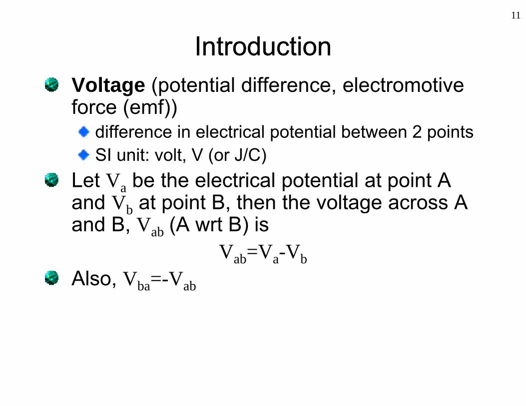
IntroductionIntroductionIntroductionIntroductionVoltage (potential difference, electromotive force (emf))force (emf))
difference in electrical potential between 2 pointsSI unit: volt V (or J/C)SI unit: volt, V (or J/C)
Let Va be the electrical potential at point A and V at point B then the voltage across Aand Vb at point B, then the voltage across A and B, Vab (A wrt B) is
V =V VVab=Va-VbAlso, Vba=-Vab
12
IntroductionIntroductionIntroductionIntroduction
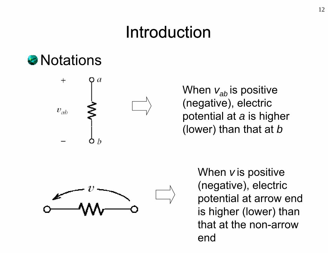
Notationsotat o s
When vab is positive ab(negative), electric potential at a is higher(l ) th th t t b(lower) than that at b
When v is positive(negative), electric(negative), electric potential at arrow endis higher (lower) than that at the non-arrow end

13
IntroductionIntroductionIntroductionIntroductionHow to measure voltage?
A Vab
4.889VV+
Vab
ve
-
B
Voltmeter
-ve+ve
http://www.youtube.com/watch?v=t0Zzoz4nM0I&

IntroductionIntroduction14
IntroductionIntroduction
Digital Multimeter (DMM) can be used g ta u t ete ( ) ca be usedto measure:
VoltageVoltageCurrentResistance

15
IntroductionIntroductionIntroductionIntroductionGround
Typical reference for electric potential
Symbol
“Voltage at point A, Va = 3.8V” means potential at point A is 3.8V with respect to ground potential

16
IntroductionIntroductionIntroductionIntroductionWhen current flows through an element and voltage appears across the element, energyis transferred.When positive charge or current enters through positive (negative) polarity into an l t i b b d ( li d) b thelement, energy is absorbed (supplied) by the
element
Energy Energy +
supplied
by the
absorbed
by the
+
element element+

17
IntroductionIntroductionIntroductionIntroduction
Power and Energyo e a d e gyPower absorbed by an element:
( ) ( ) ( )p t v t i t *
*Remark: Note this formula is based on convention that current i is flowing across element by entering through positive polarity of element. If inverse is true computed value for p is negative and it means that element actually
Energy absorbed from time t to t :
true, computed value for p is negative and it means that element actually supplies power to rest of circuit.
Energy absorbed from time t1 to t2:2
( )t
d1
( )t
w p t dt t1 < t2

18
Basic ElectricalBasic Electrical ElementsElementsBasic ElectricalBasic Electrical ElementsElements
A l t i l i it i i t ti fAn electrical circuit is an interconnection of electrical elements and energy sources.Energy sources
Voltage source (Vs), current source (Is)Ideal energy sources: Contain no internal
resistance, inductance, or capacitance.Three basic passive* electrical elements
Resistors (R), capacitors (C) , inductors (L)
*Passive elements: Require no additional power supply ( d ith i t t d i it (IC ))(compared with integrated circuits (ICs))

19
Basic ElectricalBasic Electrical ElementsElementsBasic ElectricalBasic Electrical ElementsElements
Ideal voltage source (V )Ideal voltage source (Vs)
Ideal independent voltage source
20
Basic ElectricalBasic Electrical ElementsElementsBasic ElectricalBasic Electrical ElementsElements
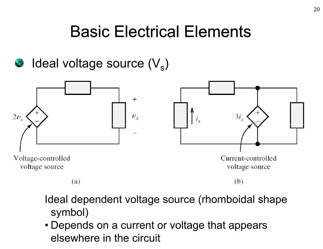
Ideal voltage source (V )Ideal voltage source (Vs)
Ideal dependent voltage source (rhomboidal shape symbol)symbol)
• Depends on a current or voltage that appears elsewhere in the circuit
21
Basic ElectricalBasic Electrical ElementsElementsBasic ElectricalBasic Electrical ElementsElements
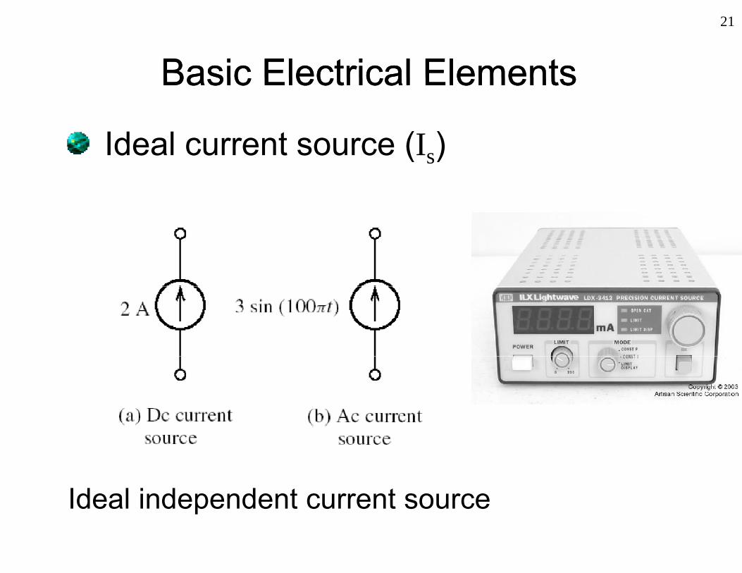
Ideal current source (I )Ideal current source (Is)
Ideal independent current sourceIdeal independent current source
22
Basic ElectricalBasic Electrical ElementsElementsBasic ElectricalBasic Electrical ElementsElements
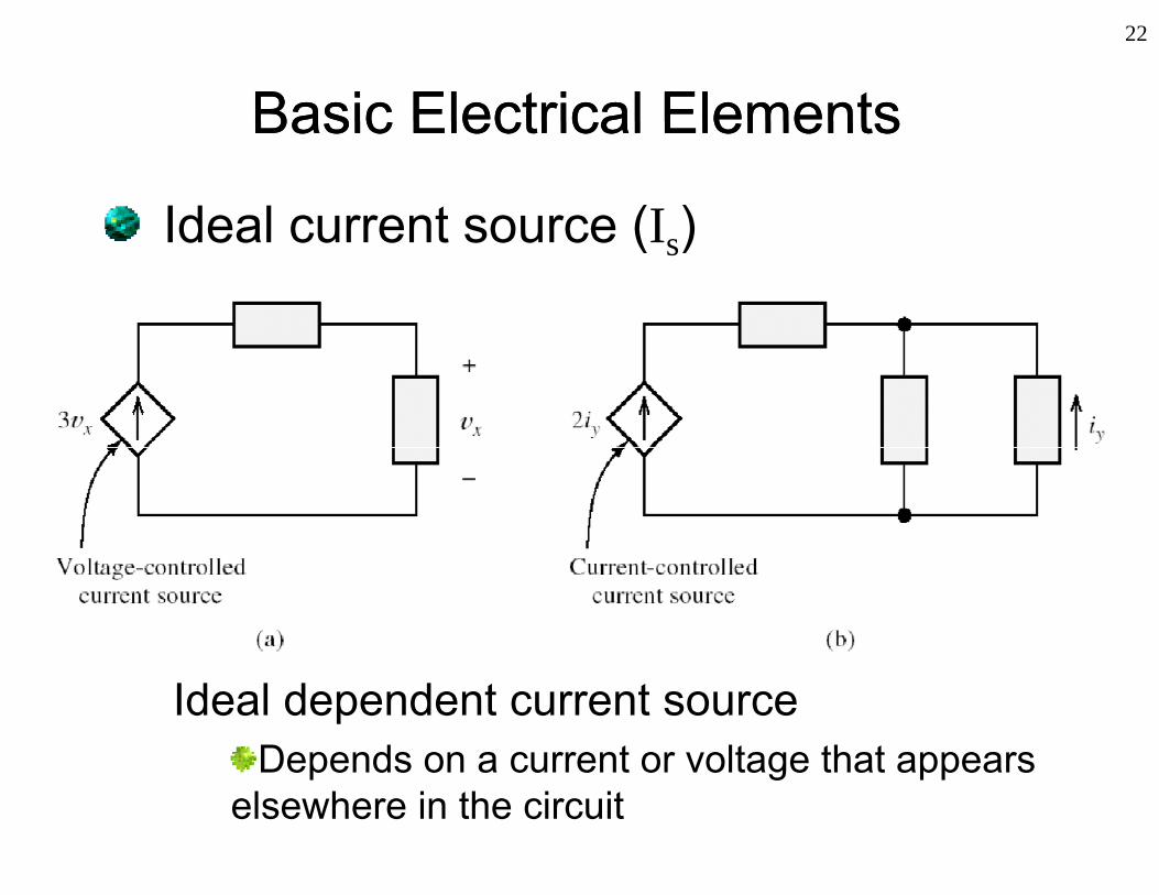
Ideal current source (I )Ideal current source (Is)
Ideal dependent current sourceDepends on a current or voltage that appears p g pp
elsewhere in the circuit

23
ResistResistororResistResistororA dissipative element: Converts electrical penergy into heat
SymbolSymbol

24
ResistResistororResistResistororIdeal resistor
Voltage-current characteristics defined by Ohm’s law:
v Ri
vi
R = v / i
i
R v / i
where R is a constant called resistance (SI Unit:
i
(Ohm, )

ResistorResistor25
ResistorResistor
Method of reading resistor’s value of wire-Method of reading resistor s value of wirelead resistors
c (%)10 toleranceabR c
10 k5%10 k5%

ResistorResistor26
ResistorResistor
Variable resistorsa ab e es sto sPotentiometer (pot)Trim potTrim pot
Three terminals
Schematic symbols

27
ResistResistororResistResistororResistance related to physical parametersp y p
E.g. Resistance of a homogeneous material of length L and with uniform cross-sectional area, A:
ALR
A
is called the resistivityfwhich is a property of the
material
http://www.youtube.com/watch?v=wUgJgK2aTG0&feature=related
How to measure resistance?

28
CapacitCapacitororCapacitCapacitororA passive element that stores energy in the form of an electric field Conducting plates
Dielectrici +
+++
----
Symbol:
material++++
----
Current flow* results in opposite charge built up on the conducting plates
Dielectric material (an insulator): increases capacitance
on the conducting plates
*Strictly, current does not flow through a capacitor

29
CapacitorCapacitorCapacitorCapacitor
Capacitor and its fluid-flow analogyCapac to a d ts u d o a a ogy

30
CapacitCapacitororCapacitCapacitoror
dv(t)
+
Cvq dtdvCi
+ -
i(t) ordt
C
where q (unit: coulombs, C): amount of accumulated charge
i h it l tappearing on each capacitor plate C (unit: farads, F (coulombs/volts)): capacitancev: voltage across the capacitorv: voltage across the capacitori : current flowing into the positive polarity of the capacitor

31
CapacitCapacitororCapacitCapacitoror
Voltage across a capacitor cannot g pchange instantaneously (why?)
Can be used for timing purposes in electricalCan be used for timing purposes in electrical circuits (e.g. RC circuit)
V
Vin
Vin
V
Used in low-pass filter
Vc
Used in low pass filter
With DC sources, capacitor behaves like an open circuit duringbehaves like an open circuit during steady state condition

32
CapacitCapacitororCapacitCapacitoror
Capacitance: A property of p p p ydielectric materialplate geometry and separationplate geometry and separation
Typical values: 1pF (picofarads, 10-12) to 1000F (microfarads, 10-6))

33
CapacitCapacitororCapacitCapacitoror
Primary types of commercial capacitors:y yp pElectrolytic (polarized, have a positive and negative ends)negative ends)TantalumC i di kCeramic diskMylar
Capacitance codes: Three-digit code e g 102 implies 10x102Three-digit code, e.g. 102, implies 10x10pF = 1 nFTwo digit code e g 22 implies 22 pFTwo-digit code, e.g. 22, implies 22 pF

34
InductorInductorInductorInductor
A passive energy storageA passive energy storage element that stores energy in the form of a magnetic field.form of a magnetic field.
Symbol:
35
InductorInductorInductorInductor
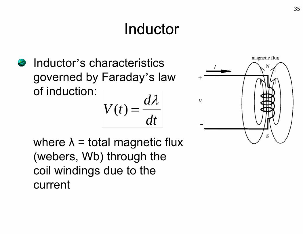
I d t ’ h t i tiInductor’s characteristics governed by Faraday’s lawf i d tiof induction:
dtdtV
)(
where λ = total magnetic flux
dtFig 2.10, p15 of Alciatore and Histand, 2003where λ total magnetic flux
(webers, Wb) through the coil windings due to thecoil windings due to the current

36
InductorInductorInductorInductorFor ideal coil, , Li hence,
di dtdiLtv
where L is the inductance (henry H (=Wb/A)) of thewhere L is the inductance (henry, H (=Wb/A)) of the coil.
1 tidttvtit
or
> C t t h i t t l
0
0
tidttvL
tit
=> Current cannot change instantaneouslyNote: With DC sources, Inductor behaves like a short circuit during steady state condition

37
InductorInductorInductorInductor
Typical inductor values: 1H to 100mHyp ca ducto a ues to 00Present in motors, relays, power s pplies oscillators circ its etcsupplies, oscillators circuits, etc
Fuel injectorElectric motors
Source: http://www.wikipedia.org/
Fuel injectorElectric motors

38
Branches, Nodes and LoopsBranches, Nodes and Loops, p, pBranch: Any portion of a circuit with two terminals
Circuitelementscircuit with two terminals
connected to it
Node: Junction of two or more branches
Node
Loop: Any closed connectionof branches
Loop 1 Loop 2
Loop 3

39
Kirchhoff’s Circuit LawsKirchhoff’s Circuit LawsKirchhoff s Circuit LawsKirchhoff s Circuit Laws
Analysis of circuits: calculate voltagesa ys s o c cu ts ca cu ate o tagesand currents anywhere in a circuit*Kirchhoff’s circ it la s essential for*Kirchhoff’s circuit laws: essential for analysis of circuits which involve various electrical elements ranging from basic elements to semiconductor components plike transistors, op amps, etc
Kirchhoff’s current law (KCL)Kirchhoff s current law (KCL)Kirchhoff’s voltage law (KVL)
*Named after Gustav Kirchhoff (1824-1887)

40
Kirchhoff’s Current LawKirchhoff’s Current LawKirchhoff s Current LawKirchhoff s Current LawSum of currents flowing into a node is zero:
N
I 0
i
iI1
0
Eg:
I1+I2-I3 = 0
(I3 has negative signbecause it is flowing away from the node)away from the node)
41
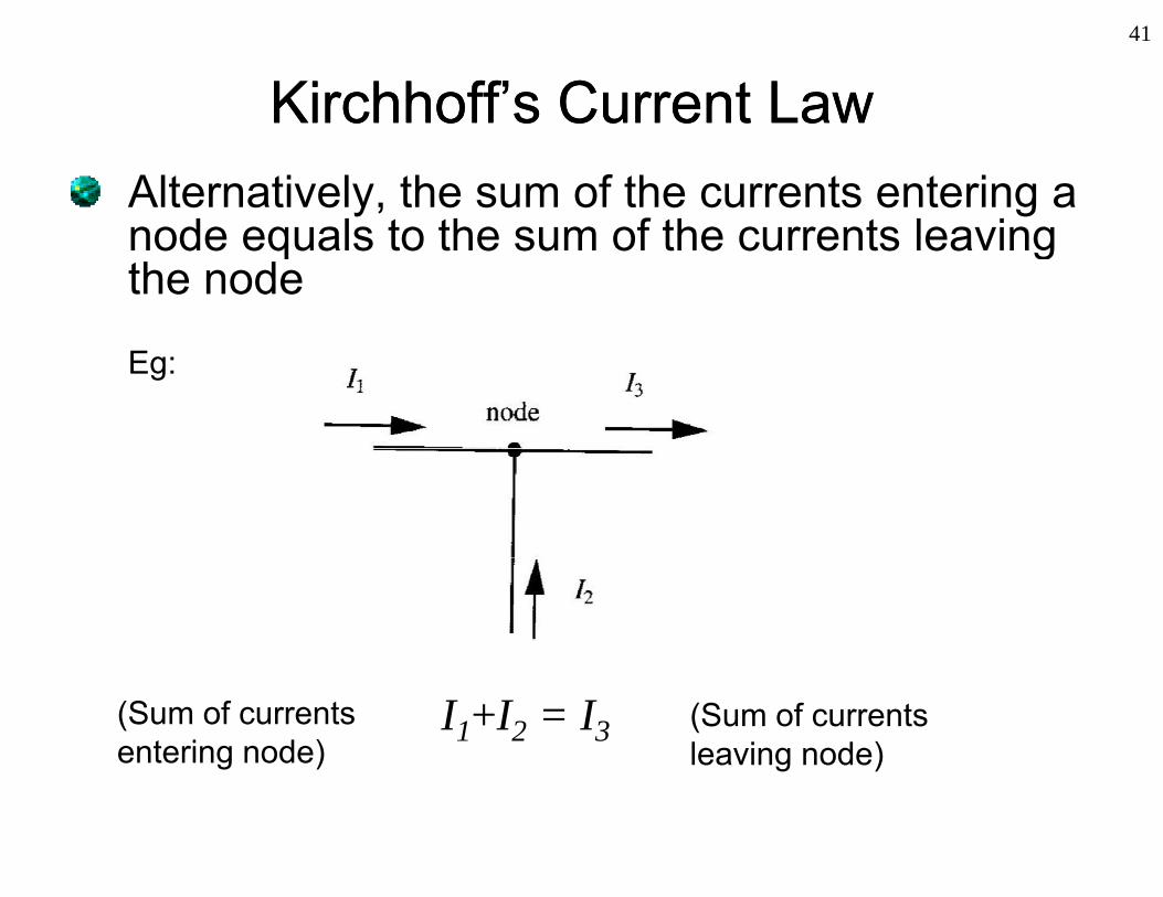
Kirchhoff’s Current LawKirchhoff’s Current LawKirchhoff s Current LawKirchhoff s Current LawAlternatively, the sum of the currents entering a node equals to the sum of the currents leavingnode equals to the sum of the currents leavingthe node
Eg:
I1+I2 = I3(Sum of currents entering node)
(Sum of currents leaving node)

42
Kirchhoff’s Voltage LawKirchhoff’s Voltage LawKirchhoff s Voltage LawKirchhoff s Voltage LawSum of voltages around a closed loop is zero:Sum of voltages around a closed loop is zero:
N
iV 0i
iV1
0
Start from a node (e gStart from a node (e.g. A) and end at the same nodenode
Either clockwise orEither clockwise or anti-clockwise is fine

43
Kirchhoff’s Voltage LawKirchhoff’s Voltage LawKirchhoff s Voltage LawKirchhoff s Voltage LawEg:Eg:
Loop 1: -v + vb + v = 0Loop 1: va + vb + vc 0Loop 2: -vc – vd + ve = 0Loop 3: v – vb + vd – v = 0Loop 3: va vb + vd ve 0

44
Analysis of circuitsAnalysis of circuitsAnalysis of circuitsAnalysis of circuitsProcedure:
• First, assign current variable to each branch and assume its flow direction.
• Then assign appropriate polarity to the voltage across each passive element (current entering into +ve polarity).
Apply KVL for loops or apply KCL for nodes to generate sufficient• Apply KVL for loops or apply KCL for nodes to generate sufficient equations together with constitutive equations of the elements (eg. Ohm’s law) to solve the unknown current and voltage variables
+ vB - - vD +
-
vA
-
vEPassive
l
+
vC
i1 i2 i3
A
+
E
+
elementvC
-

45
Systematic Circuits Analysis MethodsSystematic Circuits Analysis MethodsSystematic Circuits Analysis MethodsSystematic Circuits Analysis Methods
For resistive circuits Node-voltage methodMesh-current method
46
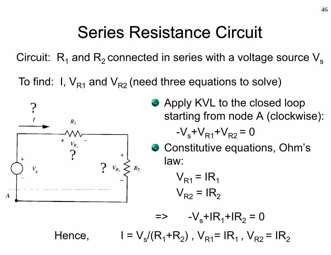
Series Resistance CircuitSeries Resistance CircuitSeries Resistance CircuitSeries Resistance CircuitCircuit: R1 and R2 connected in series with a voltage source Vs
To find: I, VR1 and VR2 (need three equations to solve)
Apply KVL to the closed loop starting from node A (clockwise):?
-Vs+VR1+VR2 = 0Constitutive equations, Ohm’s l? law:
VR1 = IR1
V IRFig 2 13 p18 Alciatore and
??
VR2 = IR2
=> -Vs+IR1+IR2 = 0
Fig 2.13, p18, Alciatore and Histand, 2003
s 1 2
Hence, I = Vs/(R1+R2) , VR1= IR1 , VR2 = IR2
47
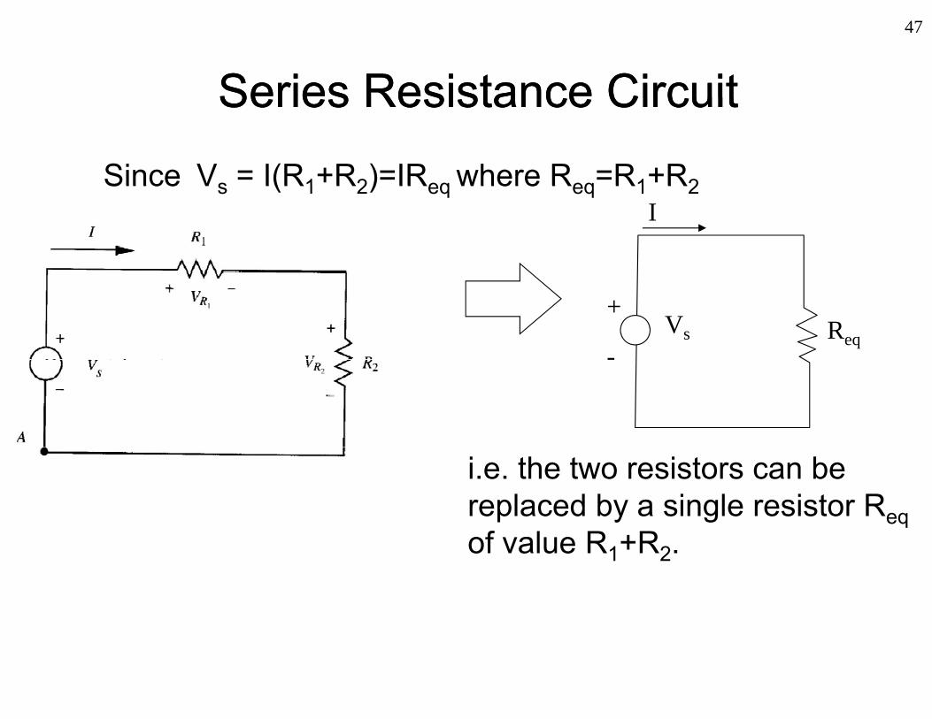
Series Resistance CircuitSeries Resistance CircuitSeries Resistance CircuitSeries Resistance Circuit
Since Vs = I(R1+R2)=IReq where Req=R1+R2Since Vs I(R1 R2) IReq where Req R1 R2I
Vs Req
+
-Fig 2.13, p18, Alciatore and -g , p ,Histand, 2003
i.e. the two resistors can be replaced by a single resistor Req
f l R Rof value R1+R2.

48
Series Resistance CircuitSeries Resistance CircuitSeries Resistance CircuitSeries Resistance Circuit
In general, N resistors connected in series is equivalent to a resistor with resistance:
N
N
ieq RR i
ieq1
where Ri is the resistance of ithresistor connected in series

49
Series Resistance CircuitSeries Resistance CircuitSeries Resistance CircuitSeries Resistance CircuitVoltage dividerg
1
11
1 2R s
RV IR VR R
2
22
1 2R s
RV IR VR R
Fig 2.13, p18, Alciatore and Histand, 1 2R R,2003
In general, voltage across the resistor Ri of N series connected resistors branch is given by:
i VRV sN
jj
R VR
Vi
1
iR RViand,
j

50
Series Resistance CircuitSeries Resistance CircuitSeries Resistance CircuitSeries Resistance CircuitVoltage divider : Create different reference gvoltages by selecting appropriate resistors.Question:Question:
Given a 12 V battery, is it appropriate to use the voltage divider to directly create a voltage source or g y gsupply of say, 5 V, for a device directly?
Vin=12VR1
VoutR2

51
Parallel Resistance CircuitParallel Resistance CircuitParallel Resistance CircuitParallel Resistance CircuitCircuit: R1 and R2 connected in parallel with a voltage source Vs
?To find: I, I1 and I2 (need three equations to solve)
Applying KCL at node A:I - I1 - I2 = 0
Constitutive equation Ohm’s law:
?
? ? Constitutive equation, Ohm s law:I1 = Vs/R1
I2 = Vs/R2Fig 2 14 p20 Alciatore and
? ?
2 s 2
V V
Fig 2.14, p20, Alciatore and Histand, 2003
=> 1 2
1 2
s sV VI I IR R

52
Parallel Resistance CircuitParallel Resistance CircuitParallel Resistance CircuitParallel Resistance Circuits
sss VVVVI
11Since where 1 1 1
R R R
eqs RRRRR
2121
I1 2eqR R R
Vs Req
+Fig 2.14, p20, Alciatore and Histand, 2003
s Req-
i.e. the two resistors can be replaced by a single resistor Req of p y g eqvalue =
1 211 1
R RR R
1 2
1 2
1 1 R RR R

53
Parallel Resistance CircuitParallel Resistance CircuitParallel Resistance CircuitParallel Resistance Circuit
In general N resistors connected inIn general, N resistors connected in parallel is equivalent to a resistor of resistance R given by:resistance, Req , given by:
1 1N1 1R R
1ieq iR R
where Ri is the resistance of ith resistor

54
Parallel Resistance CircuitParallel Resistance CircuitParallel Resistance CircuitParallel Resistance CircuitCurrent divider
1 2
1 2S eq
R RV IR IR R
2SV RFig 2.14, p20,
1 2R R
21
1 1 2
SV RI IR R R
Alciatore and Histand, 2003
12
SV RI IR R R
2 1 2R R R
That is, and1 2I R 2 1I R

55
Series Capacitors/Inductors CircuitSeries Capacitors/Inductors CircuitSeries Capacitors/Inductors CircuitSeries Capacitors/Inductors Circuit
By applying KVL, it can be shown that:
L1 L2C1 C2C1 C2
CC
In general NI l
21 LLLeq 21
21
CCCCCeq
1
1 1N
ieq iC C
In general
1
N
eq ii
L L
In general
56
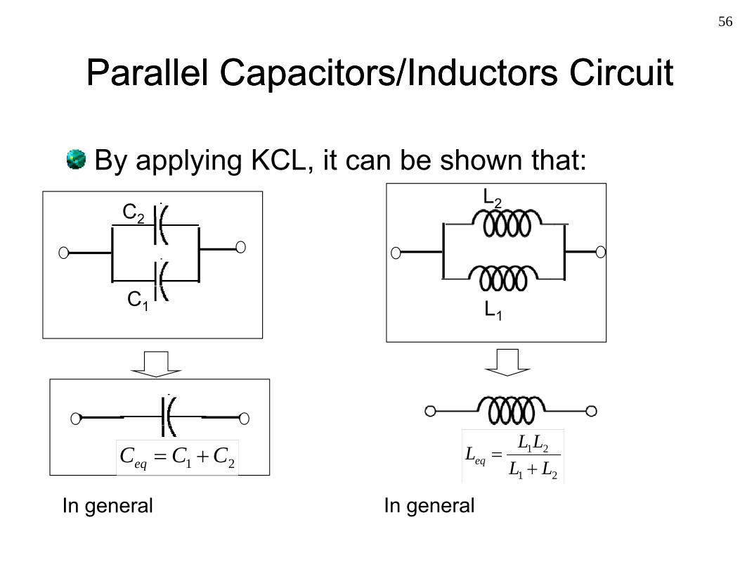
Parallel Capacitors/Inductors CircuitParallel Capacitors/Inductors CircuitParallel Capacitors/Inductors CircuitParallel Capacitors/Inductors Circuit
By applying KCL, it can be shown that:
C2L2C2
C1 L1
N N
21 CCCeq 21
21
LLLLLeq
1
N
eq ii
C C
In general
1
1 1N
ieq iL L
In general

57
Principle of SuperpositionPrinciple of SuperpositionPrinciple of SuperpositionPrinciple of Superposition
For a linear system:For a linear system:
Input u Output yInput Output
Given:
SystemInput, u1 Output, y1
au1+ bu2 ay1+by2System
Input, u2 Output, y2where a and b are some constantsSystem
Apply to linear circuits (for example thoseApply to linear circuits (for example, those which consist of ideal sources and passive
)elements)
58
Principle of SuperpositionPrinciple of SuperpositionPrinciple of SuperpositionPrinciple of Superposition
If more than one independent voltage or current source is present in any given circuit, each branch voltage and current is the sumeach branch voltage and current is the sum of the independent voltages or currentswhich would arise from each voltage orwhich would arise from each voltage or current source acting individually when all th th i d d t *the other independent sources are zero*.
*To zero a source, current source replaced by open circuit and voltage source by short circuitopen circuit and voltage source by short circuit.

59
Example: SuperpositionExample: Superpositionp p pp p p
VTo find I II1: Portion of Ii i f IRI2 I1
I ?
arising from I1II2: Portion of Iarising from I2
R
(a)(b)
? arising from I2IV: Portion of Iarising from V
RI2
RI1
II1
( )
2
II2V(c)
Ans: I=I +I +I
R
IV Ans: I II1+II2+IV
=I1-I2
V

60
Equivalent CircuitsEquivalent Circuits
Equivalent circuitsEquivalent circuits
Portion of circuit to be replaced with an
Equivalent circuitp
equivalent circuit
61
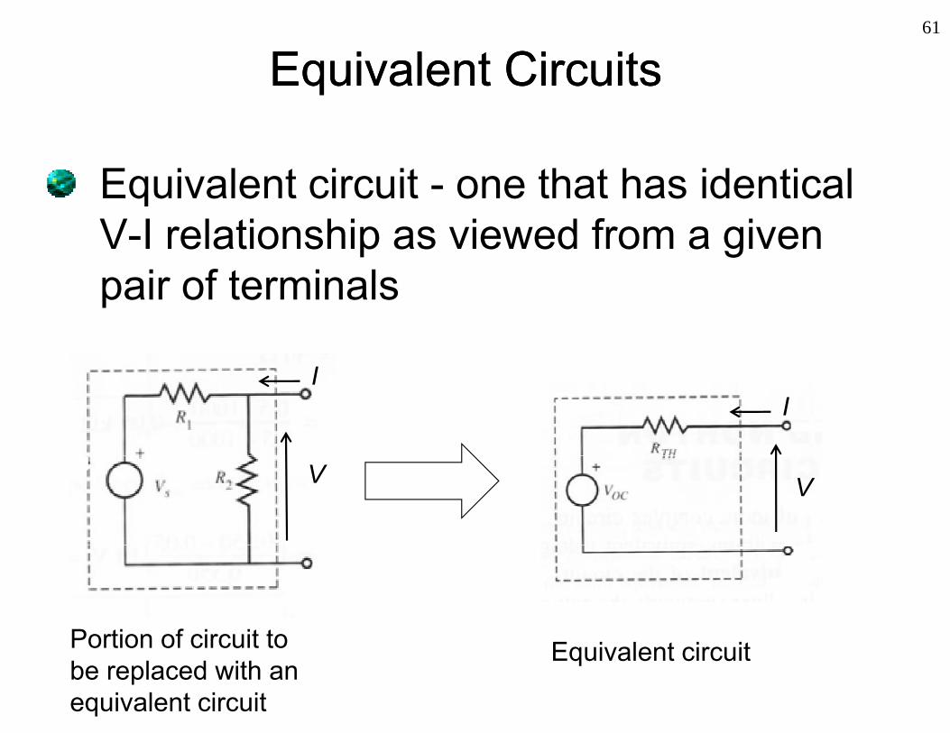
Equivalent CircuitsEquivalent Circuits
Equivalent circuit - one that has identicalEquivalent circuit - one that has identical V-I relationship as viewed from a given pair of terminalspair of terminals
III
V V
P ti f i it t Equivalent circuitPortion of circuit to be replaced with an equivalent circuit

62
Thévenin EquivalentThévenin EquivalentThévenin EquivalentThévenin EquivalentThévenin’s theorem: Given a pair of terminals in a linear resistive network, the network may be replaced by an independent voltage source V in series with avoltage source VOC in series with a resistance RTH.:
I RTHI
R1LinearV
VOCV
Vin
R2
Linear resistive
t kR2network
VOC - Thévenin voltage RTH - Thévenin resistance

63
Thévenin Equivalent (procedures)Thévenin Equivalent (procedures)Thévenin Equivalent (procedures)Thévenin Equivalent (procedures)
Thévenin voltage - open circuit voltageThévenin voltage open circuit voltageacross the terminals.Thévenin resistance equivalentThévenin resistance – equivalent resistance across the terminals when independent oltage so rces areindependent voltage sources are shorted and independent current
l d b i itsources are replaced by open circuit.(Applicable only if there is no dependent ( ysources in the circuit)

64
ExampleExample:: Thévenin Equivalent Thévenin Equivalent pp qqFind the Thevenin equivalent circuit as seen from terminals A d BA and B
Solution:
Vin
R1
Find VOC by voltage dividerA
R2
R
Find VOC by voltage dividerformula,
A
VOC
2
RRRVV inoc
B
21 RR

65
ExampleExample:: Thévenin Equivalent Thévenin Equivalent pp qq
Solution (cont):
Find RTH across the terminals A &
( )
R1B after replacing the voltage source with a short circuit:
A
R21 2|| R RR R R
A
1 21 2
||THR R RR R
B

66
ExampleExample:: Thévenin Equivalent Thévenin Equivalent pp qq
Thévenin Equivalent:
R A
VOCRTH
+Vin
R1
A
A
VOCR2
B B

67
Norton EquivalentNorton EquivalentNorton EquivalentNorton EquivalentNorton equivalent: Linear resistive network can be replaced by an independent current source I andreplaced by an independent current source ISC and Thevenin resistance RTH in parallel with the source.
ILinear
I
ISCRTH V
Linearresistive V
network
ISC - Norton current R Thevenin resistanceRTH - Thevenin resistance

68
Norton Equivalent (procedures)Norton Equivalent (procedures)Norton Equivalent (procedures)Norton Equivalent (procedures)ISC - current that would flow through the terminals if they were shorted togetherthey were shorted together.To convert to Thevenin equivalent circuit, we can compute Thevenin voltage VOC as follows:compute Thevenin voltage VOC as follows:
THSCOC RIV
IRTH
ITHSCOC
ISCRTH V
VOCV
Thevenin equivalentNorton equivalent
69
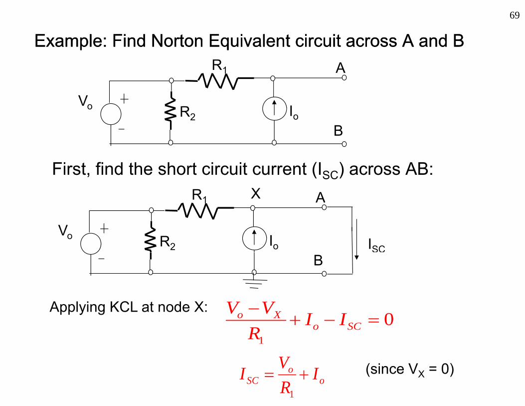
ExampleExample:: Find Find Norton EquivalentNorton Equivalent circuit across A and Bcircuit across A and B
Vo
R1 A
Vo IoR2B
First, find the short circuit current (ISC) across AB:R1 AX
Vo IoR2 ISC
A l i KCL t d X V V
B
Applying KCL at node X:
1
0o Xo SC
V V I IR
oo
SC IRVI
1
(since VX = 0)

70
Example Example -- Norton Equivalent (cont.)Norton Equivalent (cont.)Next, find the Thevenin resistance:
Replace voltage source with short circuit and current source withReplace voltage source with short circuit and current source with open circuit and inspect the equivalent resistance across the terminals. R1 A
R2BB
RTH= RAB= R1TH AB 1
Thus the Norton equivalent circuit would be:A
R1oo I
RV
BR1

Practical ConsiderationsPractical Considerations71
Practical ConsiderationsPractical Considerations
Breadboardeadboa dFor prototyping circuits Instruments for powering
and making t i i itmeasurements in circuits
Points are internally connected as showny

Practical ConsiderationsPractical Considerations
73
Practical ConsiderationsPractical Considerations
Impedance (AC concept of resistance) matchingM i t i iMaximum power transmission
In order to transmit maximum power to a load from a source, the load’s impedance should match the source’s impedance (see p p (textbook for proof).
For example, when you select speakers, the audio amplifier output impedance should be considered for maximum poweroutput impedance should be considered for maximum power transmission to a load (speaker).
Practical ConsiderationsPractical Considerations
74
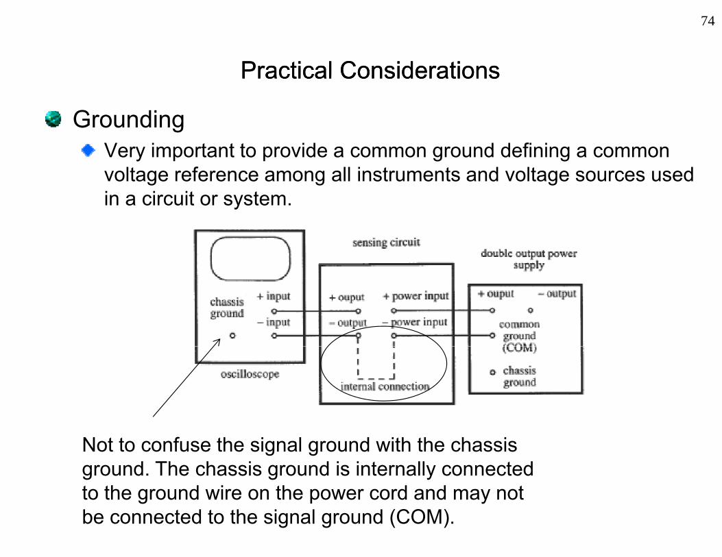
Practical ConsiderationsPractical Considerations
GroundingV i t t t id d d fi iVery important to provide a common ground defining a common voltage reference among all instruments and voltage sources used in a circuit or system.
Not to confuse the signal ground with the chassis ground. The chassis ground is internally connected to the ground wire on the power cord and may not be connected to the signal ground (COM).
75
Review of Electrical CircuitsReview of Electrical Circuits TheoryTheory
IntroductionBasic Electrical ElementsKirchhoff’s LawsPrinciple of Superposition Equivalent Circuitsqu a e t C cu tsPractical Considerations