Circolatori e Pompe in Linea · • Acqua, acqua con glicole, in miscele con oltre il 20% di...
54
SAFETY EVERYWHERE. Catalogo circolatori ed elettropompe in linea. Circulators and in line electric pumps catalogue. CATALOGO TECNICO TECHNICAL CATALOGUE
Transcript of Circolatori e Pompe in Linea · • Acqua, acqua con glicole, in miscele con oltre il 20% di...

SAFETY EVERYWHERE.
Catalogo circolatori ed elettropompe in linea. Circulators and in line electric pumps catalogue.
CATALOGO TECNICO TECHNICAL CATALOGUE

Circolatori e Pompe in linea
3
INDICE
CIRCOLATORI FILETTATI AD ALTA EFFICIENZA
HIGH-EFFICIENCY THREADED CIRCULATION PUMPS
NMT PAG. 4
NMT SMART PAG. 8
CIRCOLATORI FLANGIATI AD ALTA EFFICIENZA
HIGH-EFFICIENCY FLANGED CIRCULATION PUMPS
NMT SMART PAG. 14
NMT PAG. 20
NMT LAN PAG. 25
CIRCOLATORI AD ALTA EFFICIENZA PER ACQUA SANITARIA
HIGH-EFFICIENCY CIRCULATION PUMPS FOR DOMESTIC HOT WATER
SAN ECO PAG. 36
ELETTROPOMPE IN LINEA SINGOLE CON INVERTER SEPARATO
SINGLE IN-LINE ELECTRIC PUMPS WITH SEPARATE FREQUENCY CONVERTER
ECL 4P PAG. 38
ECL 2P PAG. 40
ELETTROPOMPE IN LINEA SINGOLE
SINGLE IN-LINE ELECTRIC PUMPS
CV 4P-2P PAG. 42
CL 4P PAG. 43
CL 2P PAG. 44
ELETTROPOMPE IN LINEA GEMELLARI
DOBLE IN-LINE ELECTRIC PUMPS
CLD 4P PAG. 51
CLD 2P PAG. 52

Circolatori e Pompe in linea
4
CIRCOLATORI FILETTATI ALTA EFFICIENZA ENERGETICA NMT
HIGH-EFFICIENCY THREADED CIRCULATION PUMPS
NMT/NMTD -/40 NMT/NMTD -/60 NMT/NMTD -/80
DESCRIZIONE
Serie di circolatori a rotore ECM bagnato ad alta efficienza
energetica e magneti permanenti con regolazione
elettronica integrata, tramite cui i circolatori si adattano alle
esigenze del sistema con regolazione a pressione
proporzionale o costante.
• Opzione SAN per l' utilizzo in sistemi di circolazione di acqua
sanitaria
• Opzione ER per regolazione ad ingresso analogico 0-10V
• Opzione D per versione gemellare APPLICAZIONI
Per la circolazione forzata di acqua o miscele di acqua/glicole in
sistemi di riscaldamento ad acqua calda, sistemi
di condizionamento dell'aria e sistemi di circolazione.
FUNZIONALITA'
Δp-p Controllo a pressione proporzionale
Il circolatore in questa modalita’ regola automaticamente la
pressione in funzione della resistenza dell’impianto in
modo da minimizzare la potenza e il consumo energetico.
Δp-c Controllo a velocità costante
Una volta selezionata questa modalita’, la pompa lavora a tre
diverse velocita’.
DETTAGLI PRODOTTO
• Tecnologia ECM ad altissima efficienza
• Risparmio energetico
• Controllo a pressione proporzionale
• Velocita’ costante
• Maneggevolezza e installazione semplici
• Plug & Play
• Struttura robusta e compatta che ne allunga la vita
• Ventilazione automatica e funzionamento silenzioso
• Corpo unico, che consente il montaggio in diverse posizioni
• Cataforesi del corpo pompa
FLUIDI CONSENTITI
• Acqua, acqua con glicole, in miscele con oltre il 20% di glicole
e’ necessario verificare i parametri
• Liquidi chiari, puliti, non aggressivi e non esplosivi, privi di olii
minerali e particelle solide o fibre
CAMPO DI TEMPERATURA AMMESSO
• Temperatura fluido da 5 ⁰C a 95 ⁰C (NMT SAN +5 ⁰C to +65 ⁰C)
ad una temperatura ambiente di massimo 40 ⁰C
PRESSIONE MINIMA IN INGRESSO
0,05 bar < 75 ⁰C Temperatura fluido
0,28 bar < 90 ⁰C Temperatura fluido
CONNESSIONE ELETTRICA
Tensione d’alimentazione 1 ~ 230 V, 50/60 Hz
MOTORE/ELETTRONICA
• Motore a magneti permanenti
• Indice energetico: EEI ≤ 0.20 - Part 2 (per NMT…-40) EEI ≤ 0.22
- Part 2 (per NMT…-60)EEI ≤ 0.24 - Part 2 (per NMT…-80)
• Protezione motore integrata
• Regolazione a Δp o velocita’ costante
• Indice di protezione IP44
• Indice di isolamento classe F
DESCRIPTION
Series of high efficiency wet running ECM rotor circulation
pumps with permanent magnets and integrated
electronic regulation with which the pumps can adapt to
current needs of the system with proportional or
constant pressure regulation.
• SAN option for use in domestic hot water circulating systems
• ER option with 0-10V analog input
• D option, twin pump
APLICATIONS
Used for circulation of water or a mixture of water/glycol in hot
water heating systems, air conditioning systems
and circulation systems.
OPERATION
Δp-Proportional pressure control
After selecting level pump recognizes the lowest resistance of
the system and automatically adjusts its own strain.
Δp-Constant speed
After selection pump works in three different speeds
PRODUCT DETAILS
• High efficiency ECM technology
• Energy savings
• Proportional pressure control
• Constant speed
• Easy handling and installation
• Robust and compact construction for long life
• Automatic venting
• Low noise operation
• Single body, which allows a variety of mounting positions
• Housing with cataphoresis
Permissible mediums
• Water, mixed with glycol, parameters must be checked in the
mixture of water with over 20% of glycol
• Pure non-explosive liquid media free from mineral oils and
without solid particles
Permissible temperature range
• Medium temperature from +5 ⁰C to +95 ⁰C (NMT SAN +5 ⁰C to
+65 ⁰C) with max. surroundings temperature up to +40 ⁰C
Minimum inlet pressure
0,05 bar < 75 ⁰C Temperature of medium
0,28 bar < 90 ⁰C Temperature of medium
Electrical connection
Voltage 1 ~ 230 V, 50/60 Hz
Motor/Electronics
• Motor with permanent magnets
• The energy index EEI ≤ 0,20 - Part 2
• Built-in motor protection
• Control Δp or constant speed
• Degree of protection: IP 44
• Insulation class F

Circolatori e Pompe in linea
5
NMT (NMTD)..- 40
Tipo pompa
Pump type
Collegamento tubo
Pipe connection DN
Interasse
Fitting length
N. pressione
N. pressure
Peso
Weight
NMT 15/40-130 Rp ½ 15 130 mm PN 10 bar 1,9 kg
NMT 20/40-130 Rp ¾ 20 130 mm PN 10 bar 2,0 kg
NMT 25/40-130 Rp 1 25 130 mm PN 10 bar 2,1 kg
NMT 20/40-180 Rp ¾ 20 180 mm PN 10 bar 2,3 kg
NMT 25/40-180 Rp 1 25 180 mm PN 10 bar 2,4 kg
NMT 32/40-180 Rp 1 ¼ 32 180 mm PN 10 bar 2,5 kg
NMTD 25/40-180 Rp 1 25 180 mm PN 10 bar 5 kg
NMTD 32/40-180 Rp 1 ¼ 30 180 mm PN 10 bar 5,2 kg
NMT SAN 20/40-130 Rp ¾ 20 130 mm PN 10 bar 2,1 kg
NMT SAN 25/40-130 Rp 1 25 130 mm PN 10 bar 2,2 kg
NMT ER 15/40-130 Rp ½ 15 130 mm PN 10 bar 1,9 kg
NMT ER 20/40-130 Rp ¾ 20 130 mm PN 10 bar 2,0 kg
NMT ER 25/40-130 Rp 1 25 130 mm PN 10 bar 2,1 kg
NMT ER 20/40-180 Rp ¾ 20 180 mm PN 10 bar 2,3 kg
NMT ER 25/40-180 Rp 1 25 180 mm PN 10 bar 2,4 kg
NMT ER 32/40-180 Rp 1 ¼ 32 180 mm PN 10 bar 2,5 kg
Dimensioni / Dimensions
Modello / Model h DN D2 b b1 b2 I a
NMT -/40 130/180 15/20/25/32 1"/5/4"/6/4"/2" 80 48 108 27/29/32
NMTD -/40 180 25/30 6/4“/2“ 234 107,2 29,8
DATI TECNICI / TECHNICAL DATA
Portata / Flow Fino a / Up to 2,6 mc/h
Pressione / Pressure Fino a / Up to 4 m
Potenza / Power 5 – 25 W
Pressione nominale / Nominal pressure 10 bar
MATERIALI / MATERIALS
Parte / Component Materiale / Material
Corpo pompa / Housing Ghisa / Cast iron
Girante / Impeller Poliammide / Polyamid
Albero / Shaft Ceramica / Ceramics
Cuscinetti / Bearings Ceramica / Ceramics
Canotto separatore / Verticular wall Acciaio inox AISI 316 / Stainless steel
Piatto di supporto / Rotor can Acciaio inox AISI 316 / Stainless steel

Circolatori e Pompe in linea
6
NMT (NMTD)..- 60
Tipo pompa
Pump type
Collegamento tubo
Pipe connection DN
Interasse
Fitting length
N. pressione
N. pressure
Peso
Weight
NMT 15/60-130 Rp ½ 15 130 mm PN 10 bar 1,9 kg
NMT 20/60-130 Rp ¾ 20 130 mm PN 10 bar 2,0 kg
NMT 25/60-130 Rp 1 25 130 mm PN 10 bar 2,1 kg
NMT 20/60-180 Rp ¾ 20 180 mm PN 10 bar 2,3 kg
NMT 25/60-180 Rp 1 25 180 mm PN 10 bar 2,4 kg
NMT 32/60-180 Rp 1 ¼ 32 180 mm PN 10 bar 2,5 kg
NMTD 25/60-180 Rp 1 25 180 mm PN 10 bar 5 kg
NMTD 32/60-180 Rp 1 ¼ 30 180 mm PN 10 bar 5,2 kg
NMT SAN 20/60-130 Rp ¾ 20 130 mm PN 10 bar 2,1 kg
NMT SAN 25/60-130 Rp 1 25 130 mm PN 10 bar 2,2 kg
NMT ER 15/60-130 Rp ½ 15 130 mm PN 10 bar 1,9 kg
NMT ER 20/60-130 Rp ¾ 20 130 mm PN 10 bar 2,0 kg
NMT ER 25/60-130 Rp 1 25 130 mm PN 10 bar 2,1 kg
NMT ER 20/60-180 Rp ¾ 20 180 mm PN 10 bar 2,3 kg
NMT ER 25/60-180 Rp 1 25 180 mm PN 10 bar 2,4 kg
NMT ER 32/60-180 Rp 1 ¼ 32 180 mm PN 10 bar 2,5 kg
Dimensioni / Dimensions
Modello / Model h DN D2 b b1 b2 I a
NMT -/60 130/180 15/20/25/32 1"/5/4"/6/4"/2" 80 48 108 27/29/32
NMTD -/60 180 25/30 6/4“/2“ 234 107,2 29,8
DATI TECNICI / TECHNICAL DATA
Portata / Flow Fino a 3,7 mc/h
Pressione / Pressure Fino a 6 m
Potenza / Power 7 – 50 W
Pressione nominale / Nominal pressure 10 bar
MATERIALI / MATERIALS
Parte / Component Materiale / Material
Corpo pompa / Housing Ghisa / Cast iron
Girante / Impeller Poliammide / Polyamid
Albero / Shaft Ceramica / Ceramics
Cuscinetti / Bearings Ceramica / Ceramics
Canotto separatore / Verticular wall Acciaio inox AISI 316 / Stainless steel
Piatto di supporto / Rotor can Acciaio inox AISI 316 / Stainless steel

Circolatori e Pompe in linea
7
NMT (NMTD)..- 80
Tipo pompa
Pump type
Collegamento tubo
Pipe connection DN
Interasse
Fitting length
N. pressione
N. pressure
Peso
Weight
NMT 15/80-130 Rp ½ 15 130 mm PN 10 bar 1,9 kg
NMT 20/80-130 Rp ¾ 20 130 mm PN 10 bar 2,0 kg
NMT 25/80-130 Rp 1 25 130 mm PN 10 bar 2,1 kg
NMT 20/80-180 Rp ¾ 20 180 mm PN 10 bar 2,3 kg
NMT 25/80-180 Rp 1 25 180 mm PN 10 bar 2,4 kg
NMT 32/80-180 Rp 1 ¼ 32 180 mm PN 10 bar 2,5 kg
NMTD 25/80-180 Rp 1 25 180 mm PN 10 bar 5 kg
NMTD 32/80-180 Rp 1 ¼ 30 180 mm PN 10 bar 5,2 kg
NMT SAN 20/80-130 Rp ¾ 20 130 mm PN 10 bar 2,1 kg
NMT SAN 25/80-130 Rp 1 25 130 mm PN 10 bar 2,2 kg
NMT ER 15/80-130 Rp ½ 15 130 mm PN 10 bar 1,9 kg
NMT ER 20/80-130 Rp ¾ 20 130 mm PN 10 bar 2,0 kg
NMT ER 25/80-130 Rp 1 25 130 mm PN 10 bar 2,1 kg
NMT ER 20/80-180 Rp ¾ 20 180 mm PN 10 bar 2,3 kg
NMT ER 25/80-180 Rp 1 25 180 mm PN 10 bar 2,4 kg
NMT ER 32/80-180 Rp 1 ¼ 32 180 mm PN 10 bar 2,5 kg
Dimensioni / Dimensions
Modello / Model h DN D2 b b1 b2 I a
NMT -/80 130/180 15/20/25/32 1"/5/4"/6/4"/2" 80 48 108 27/29/32
NMTD -/80 180 25/30 6/4“/2“ 234 107,2 29,8
DATI TECNICI / TECHNICAL DATA
Portata / Flow Fino a / Up to 4,5 mc/h
Pressione / Pressure Fino a / Up to 8 m
Potenza / Power 7 – 75 W
Pressione nominale / Nominal pressure 10 bar
MATERIALI / MATERIALS
Parte / Component Materiale / Material
Corpo pompa / Housing Ghisa / Cast iron
Girante / Impeller Poliammide / Polyamid
Albero / Shaft Ceramica / Ceramics
Cuscinetti / Bearings Ceramica / Ceramics
Canotto separatore / Verticular wall Acciaio inox AISI 316 / Stainless steel
Piatto di supporto / Rotor can Acciaio inox AISI 316 / Stainless steel

Circolatori e Pompe in linea
8
CIRCOLATORI FILETTATI ALTA EFFICIENZA ENERGETICA NMT SMART
HIGH-EFFICIENCY THREADED CIRCULATION PUMPS
NMT/NMTD SMART- /40 /60 /80 /100 /120
DESCRIZIONE
Serie di circolatori a rotore ECM bagnato ad alta efficienza
energetica e magneti permanenti con regolazione elettronica
integrata, tramite cui i circolatori si adattano alle esigenze del
sistema.
• Opzione D per versione gemellare
• Opzione C per versione con modulo di comunicazione
APPLICAZIONI
Per la circolazione forzata di acqua o miscele di acqua/glicole in
sistemi di riscaldamento ad acqua calda, sistemi di
condizionamento dell'aria e sistemi di circolazione.
FUNZIONALITA'
• Modalità automatica (preimpostata).
• Regolazione a pressione proporzionale
• Regolazione a pressione costante
• Velocita' costante
• Modalita' notturna
DETTAGLI PRODOTTO
• Tecnologia ECM ad altissima efficienza
• Risparmio energetico
• Display di controllo a LED
• Maneggevolezza e installazione semplici
• Plug & Play
• Struttura robusta e compatta che ne allunga la vita
• Ventilazione automatica
• Cataforesi del corpo pompa
• Modulo di comunicazione / SMART C (opzionale)
- connessione Ethernet
- Modbus RTU
- ingresso a controllo analogico 0-10V
- 3 ingressi digitali
- 1 uscita a relay
FLUIDI CONSENTITI
• Acqua, acqua con glicole, in miscele con oltre il 20% di glicole
e’ necessario verificare i parametri
• Liquidi chiari, puliti, non aggressivi e non esplosivi, privi di olii
minerali e particelle solide o fibre
CAMPO DI TEMPERATURA AMMESSO
• Temperatura fluido da 2 ⁰C a 110 ⁰C ad una temperatura
ambiente di massimo 40 ⁰C
PRESSIONE MINIMA IN INGRESSO
0,05 bar < 75 ⁰C Temperatura fluido
0,28 bar < 90 ⁰C Temperatura fluido
CONNESSIONE ELETTRICA
Tensione d’alimentazione 1 ~ 230 V, 50/60 Hz
MOTORE/ELETTRONICA
• Motore a magneti permanenti
• Indice energetico: EEI ≤ 0.21 - Part 2
• Protezione motore integrata
• Indice di protezione IP44
• Indice di isolamento classe F
DESCRIPTION Series of high efficiency wet running ECM rotor circulation
pumps with permanent magnets and integrated
electronic regulation with which the pumps can adapt to
current needs of the system.
• D option, twin pump
• C option with communication module
APPLICATIONS
Used for circulation of water or a mixture of water/glycol in hot
water heating systems, air conditioning systems
and circulation systems.
OPERATION
• Auto mode (default)
• Proportional pressure control
• Constant pressure control
• Constant speed
• Night mode
PRODUCT DETAILS
• High efficiency ECM technology
• Energy savings
• LED Display for control
• Easy handling and installation
• Plug & Play
• Robust and compact construction for long life
• Automatic venting
• Low noise operation
• Housing with cataphoresis
• NMTC communication module (optionally):
- Ethernet connection
- Modbus RTU connection
- Analog Control input 0 - 10 V
- 3 digital inputs
- 1 relay output
Permissible mediums
• Water, mixed with glycol, parameters must be checked in the
mixture of water with over 20% of glycol
• Pure non-explosive liquid media free from mineral oils and
without solid particles
Permissible temperature range
• Medium temperature from +2 ⁰C to +110 ⁰C with max.
surroundings temperature up to +40 ⁰C
Minimum inlet pressure
0,05 bar < 75 ⁰C Temperature of medium
0,28 bar < 90 ⁰C Temperature of medium
Electrical connection
Voltage 1 ~ 230 V, 50/60 Hz
Motor/Electronics
• Motor with permanent magnets
• The energy index EEI ≤ 0,21 - Part 2
• Built-in motor protection
• Degree of protection: IP 44
• Insulation class F

Circolatori e Pompe in linea
9
NMT (NMTD) SMART..- 40
Tipo pompa
Pump type
Collegamento tubo
Pipe connection DN
Interasse
Fitting length
N. pressione
N. pressure
Peso
Weight
NMT SMART 25/40 Rp 1 25 180 mm PN 10 bar 4 kg
NMT SMART 32/40 Rp 1 ¼ 32 180 mm PN 10 bar 4,1 kg
NMT SMART C 25/40 Rp 1 25 180 mm PN 10 bar 4,2 kg
NMT SMART C 32/40 Rp 1 ¼ 32 180 mm PN 10 bar 4,3 kg
NMTD SMART 32/40 Rp 1 ¼ 32 180 mm PN 10 bar 8,2 kg
NMTD SMART C 32/40 Rp 1 ¼ 32 180 mm PN 10 bar 8,6 kg
Dimensioni / Dimensions
Modello / Model h DN D2 B I a
NMT SMART 25/40 180 25 6/4" 117 190 53
NMT SMART 32/40 180 32 2" 117 190 53
NMT SMART C 25/40 180 25 6/4" 117 222 53
NMT SMART C 32/40 180 32 2" 117 222 53
NMTD SMART 32/40 180 32 2“ 297 190 56
NMTD SMART C 32/40 180 32 2" 297 222 56
DATI TECNICI / TECHNICAL DATA
Portata / Flow Fino a / Up to 7,5 mc/h
Pressione / Pressure Fino a / Up to 4 m
Potenza / Power 7 – 60 W
Pressione nominale / Nominal pressure 10 bar
MATERIALI / MATERIALS
Parte / Component Materiale / Material
Corpo pompa / Housing Ghisa / Cast iron
Girante / Impeller PES
Albero / Shaft Acciaio inox / Stainless steel
Cuscinetti / Bearings Grafite / Graphite
Canotto separatore / Verticular wall Acciaio inox AISI 316 / Stainless steel
Piatto di supporto / Rotor can Acciaio inox AISI 316 / Stainless steel

Circolatori e Pompe in linea
10
NMT (NMTD) SMART..- 60
Tipo pompa
Pump type
Collegamento tubo
Pipe connection DN
Interasse
Fitting length
N. pressione
N. pressure
Peso
Weight
NMT SMART 25/60 Rp 1 25 180 mm PN 10 bar 4 kg
NMT SMART 32/60 Rp 1 ¼ 32 180 mm PN 10 bar 4,1 kg
NMT SMART C 25/60 Rp 1 25 180 mm PN 10 bar 4,2 kg
NMT SMART C 32/60 Rp 1 ¼ 32 180 mm PN 10 bar 4,3 kg
NMTD SMART 32/60 Rp 1 ¼ 32 180 mm PN 10 bar 8,2 kg
NMTD SMART C 32/60 Rp 1 ¼ 32 180 mm PN 10 bar 8,6 kg
Dimensioni / Dimensions
Modello / Model h DN D2 B I a
NMT SMART 25/60 180 25 6/4" 117 190 53
NMT SMART 32/60 180 32 2" 117 190 53
NMT SMART C 25/60 180 25 6/4" 117 222 53
NMT SMART C 32/60 180 32 2" 117 222 53
NMTD SMART 32/60 180 32 2“ 297 190 56
NMTD SMART C 32/60 180 32 2" 297 222 56
DATI TECNICI / TECHNICAL DATA
Portata / Flow Fino a / Up to 9 mc/h
Pressione / Pressure Fino a / Up to 6 m
Potenza / Power 7 – 90 W
Pressione nominale / Nominal pressure 10 bar
MATERIALI / MATERIALS
Parte / Component Materiale / Material
Corpo pompa / Housing Ghisa / Cast iron
Girante / Impeller PES
Albero / Shaft Acciaio inox / Stainless steel
Cuscinetti / Bearings Grafite / Graphite
Canotto separatore / Verticular wall Acciaio inox AISI 316 / Stainless steel
Piatto di supporto / Rotor can Acciaio inox AISI 316 / Stainless steel

Circolatori e Pompe in linea
11
NMT (NMTD) SMART..- 80
Tipo pompa
Pump type
Collegamento tubo
Pipe connection DN
Interasse
Fitting length
N. pressione
N. pressure
Peso
Weight
NMT SMART 25/80 Rp 1 25 180 mm PN 10 bar 4 kg
NMT SMART 32/80 Rp 1 ¼ 32 180 mm PN 10 bar 4,1 kg
NMT SMART C 25/80 Rp 1 25 180 mm PN 10 bar 4,2 kg
NMT SMART C 32/80 Rp 1 ¼ 32 180 mm PN 10 bar 4,3 kg
NMTD SMART 32/80 Rp 1 ¼ 32 180 mm PN 10 bar 8,2 kg
NMTD SMART C 32/80 Rp 1 ¼ 32 180 mm PN 10 bar 8,6 kg
Dimensioni / Dimensions
Modello / Model h DN D2 B I a
NMT SMART 25/80 180 25 6/4" 117 190 53
NMT SMART 32/80 180 32 2" 117 190 53
NMT SMART C 25/80 180 25 6/4" 117 222 53
NMT SMART C 32/80 180 32 2" 117 222 53
NMTD SMART 32/80 180 32 2“ 297 190 56
NMTD SMART C 32/80 180 32 2" 297 222 56
DATI TECNICI / TECHNICAL DATA
Portata / Flow Fino a / Up to 10 mc/h
Pressione / Pressure Fino a / Up to 8 m
Potenza / Power 7 – 140 W
Pressione nominale / Nominal pressure 10 bar
MATERIALI / MATERIALS
Parte / Component Materiale / Material
Corpo pompa / Housing Ghisa / Cast iron
Girante / Impeller PES
Albero / Shaft Acciaio inox / Stainless steel
Cuscinetti / Bearings Grafite / Graphite
Canotto separatore / Verticular wall Acciaio inox AISI 316 / Stainless steel
Piatto di supporto / Rotor can Acciaio inox AISI 316 / Stainless steel

Circolatori e Pompe in linea
12
NMT (NMTD) SMART..- 100
Tipo pompa
Pump type
Collegamento tubo
Pipe connection DN
Interasse
Fitting length
N. pressione
N. pressure
Peso
Weight
NMT SMART 25/100 Rp 1 25 180 mm PN 10 bar 4 kg
NMT SMART 32/100 Rp 1 ¼ 32 180 mm PN 10 bar 4,1 kg
NMT SMART C 25/100 Rp 1 25 180 mm PN 10 bar 4,2 kg
NMT SMART C 32/100 Rp 1 ¼ 32 180 mm PN 10 bar 4,3 kg
NMTD SMART 32/100 Rp 1 ¼ 32 180 mm PN 10 bar 8,2 kg
NMTD SMART C 32/100 Rp 1 ¼ 32 180 mm PN 10 bar 8,6 kg
Dimensioni / Dimensions
Modello / Model h DN D2 B I a
NMT SMART 25/100 180 25 6/4" 117 190 53
NMT SMART 32/100 180 32 2" 117 190 53
NMT SMART C 25/100 180 25 6/4" 117 222 53
NMT SMART C 32/100 180 32 2" 117 222 53
NMTD SMART 32/100 180 32 2“ 297 190 56
NMTD SMART C 32/100 180 32 2" 297 222 56
DATI TECNICI / TECHNICAL DATA
Portata / Flow Fino a / Up to 11 mc/h
Pressione / Pressure Fino a / Up to 10 m
Potenza / Power 7 – 180 W
Pressione nominale / Nominal pressure 10 bar
MATERIALI / MATERIALS
Parte / Component Materiale / Material
Corpo pompa / Housing Ghisa / Cast iron
Girante / Impeller PES
Albero / Shaft Acciaio inox / Stainless steel
Cuscinetti / Bearings Grafite / Graphite
Canotto separatore / Verticular wall Acciaio inox AISI 316 / Stainless steel
Piatto di supporto / Rotor can Acciaio inox AISI 316 / Stainless steel

Circolatori e Pompe in linea
13
NMT (NMTD) SMART..- 120
Tipo pompa
Pump type
Collegamento tubo
Pipe connection DN
Interasse
Fitting length
N. pressione
N. pressure
Peso
Weight
NMT SMART 25/120 Rp 1 25 180 mm PN 10 bar 4 kg
NMT SMART 32/120 Rp 1 ¼ 32 180 mm PN 10 bar 4,1 kg
Dimensioni / Dimensions
Modello / Model h DN D2 B I a
NMT SMART 25/120 180 25 6/4" 117 190 53
NMT SMART 32/120 180 32 2" 117 190 53
DATI TECNICI / TECHNICAL DATA
Portata / Flow Fino a / Up to 11 mc/h
Pressione / Pressure Fino a / Up to 12 m
Potenza / Power 7 – 180 W
Pressione nominale / Nominal pressure 10 bar
MATERIALI / MATERIALS
Parte / Component Materiale / Material
Corpo pompa / Housing Ghisa / Cast iron
Girante / Impeller PES
Albero / Shaft Acciaio inox / Stainless steel
Cuscinetti / Bearings Grafite / Graphite
Canotto separatore / Verticular wall Acciaio inox AISI 316 / Stainless steel
Piatto di supporto / Rotor can Acciaio inox AISI 316 / Stainless steel

Circolatori e Pompe in linea
14
CIRCOLATORI FLANGIATI ALTA EFFICIENZA ENERGETICA NMT SMART
HIGH-EFFICIENCY FLANGED CIRCULATION PUMPS
NMT/NMTD SMART- /40 F /60 F /80 F /100 F /120 F
DESCRIZIONE
Serie di circolatori a rotore ECM bagnato ad alta efficienza
energetica e magneti permanenti con regolazione elettronica
integrata, tramite cui i circolatori si adattano alle esigenze del
sistema.
• Opzione D per versione gemellare
• Opzione C per versione con modulo di comunicazione
APPLICAZIONI
Per la circolazione forzata di acqua o miscele di acqua/glicole in
sistemi di riscaldamento ad acqua calda, sistemi di
condizionamento dell'aria e sistemi di circolazione.
FUNZIONALITA'
• Modalità automatica (preimpostata).
• Regolazione a pressione proporzionale
• Regolazione a pressione costante
• Velocita' costante
• Modalita' notturna
DETTAGLI PRODOTTO
• Tecnologia ECM ad altissima efficienza
• Risparmio energetico
• Display di controllo a LED
• Maneggevolezza e installazione semplici
• Plug & Play
• Struttura robusta e compatta che ne allunga la vita
• Ventilazione automatica
• Cataforesi del corpo pompa
• Modulo di comunicazione / SMART C (opzionale)
- connessione Ethernet
- Modbus RTU
- ingresso a controllo analogico 0-10V
- 3 ingressi digitali
- 1 uscita a relay
FLUIDI CONSENTITI
• Acqua, acqua con glicole, in miscele con oltre il 20% di glicole
e’ necessario verificare i parametri
• Liquidi chiari, puliti, non aggressivi e non esplosivi, privi di olii
minerali e particelle solide o fibre
CAMPO DI TEMPERATURA AMMESSO
• Temperatura fluido da 2 ⁰C a 110 ⁰C ad una temperatura
ambiente di massimo 40 ⁰C
PRESSIONE MINIMA IN INGRESSO
0,05 bar < 75 ⁰C Temperatura fluido
0,28 bar < 90 ⁰C Temperatura fluido
CONNESSIONE ELETTRICA
Tensione d’alimentazione 1 ~ 230 V, 50/60 Hz
MOTORE/ELETTRONICA
• Motore a magneti permanenti
• Indice energetico: EEI ≤ 0.21 - Part 2
• Protezione motore integrata
• Indice di protezione IP44
• Indice di isolamento classe F
DESCRIPTION Series of high efficiency wet running ECM rotor circulation
pumps with permanent magnets and integrated
electronic regulation with which the pumps can adapt to
current needs of the system.
• D option, twin pump
• C option with communication module
APPLICATIONS
Used for circulation of water or a mixture of water/glycol in hot
water heating systems, air conditioning systems
and circulation systems.
OPERATION
• Auto mode (default)
• Proportional pressure control
• Constant pressure control
• Constant speed
• Night mode
PRODUCT DETAILS
• High efficiency ECM technology
• Energy savings
• LED Display for control
• Easy handling and installation
• Plug & Play
• Robust and compact construction for long life
• Automatic venting
• Low noise operation
• Housing with cataphoresis
• NMTC communication module (optionally):
- Ethernet connection
- Modbus RTU connection
- Analog Control input 0 - 10 V
- 3 digital inputs
- 1 relay output
Permissible mediums
• Water, mixed with glycol, parameters must be checked in the
mixture of water with over 20% of glycol
• Pure non-explosive liquid media free from mineral oils and
without solid particles
Permissible temperature range
• Medium temperature from +2 ⁰C to +110 ⁰C with max.
surroundings temperature up to +40 ⁰C
Minimum inlet pressure
0,05 bar < 75 ⁰C Temperature of medium
0,28 bar < 90 ⁰C Temperature of medium
Electrical connection
Voltage 1 ~ 230 V, 50/60 Hz
Motor/Electronics
• Motor with permanent magnets
• The energy index EEI ≤ 0,21 - Part 2
• Built-in motor protection
• Degree of protection: IP 44
• Insulation class F

Circolatori e Pompe in linea
15
NMT (NMTD) SMART..- 40 F
Tipo pompa
Pump type
Collegamento tubo
Pipe connection DN
Interasse
Fitting length
N. pressione
N. pressure
NMT SMART 32/40 F 32 220 mm PN 6/10 bar 7,4 kg
NMT SMART 40/40 F 40 220 mm PN 6/10 bar 8,5 kg
NMT SMART C 32/40 F 32 220 mm PN 6/10 bar 7,6 kg
NMT SMART C 40/40 F 40 220 mm PN 6/10 bar 8,7 kg
NMTD SMART 40/40 F 40 220 mm PN 6/10 bar 12,3 kg
NMTD SMART C 40/40 F 40 220 mm PN 6/10 bar 12,7 kg
Dimensioni / Dimensions
Modello / Model h DN B I a
NMT SMART 32/40 F 220 32 117 190 70
NMT SMART 40/40 F 220 40 117 190 75
NMT SMART C 32/40 F 220 32 117 222 70
NMT SMART C 40/40 F 220 40 117 222 75
NMTD SMART 40/40 F 220 40 297 190 56
NMTD SMART C 40/40 F 220 40 297 222 56
DATI TECNICI / TECHNICAL DATA
Portata / Flow Fino a / Up to 7,5 mc/h
Pressione / Pressure Fino a / Up to 4 m
Potenza / Power 7 – 60 W
Pressione nominale / Nominal pressure 10 bar
MATERIALI / MATERIALS
Parte / Component Materiale / Material
Corpo pompa / Housing Ghisa / Cast iron
Girante / Impeller PES
Albero / Shaft Acciaio inox / Stainless steel
Cuscinetti / Bearings Grafite / Graphite
Canotto separatore / Verticular wall Acciaio inox AISI 316 / Stainless steel
Piatto di supporto / Rotor can Acciaio inox AISI 316 / Stainless steel

Circolatori e Pompe in linea
16
NMT (NMTD) SMART..- 60 F
Tipo pompa
Pump type
Collegamento tubo
Pipe connection DN
Interasse
Fitting length
N. pressione
N. pressure
NMT SMART 32/60 F 32 220 mm PN 6/10 bar 7,4 kg
NMT SMART 40/60 F 40 220 mm PN 6/10 bar 8,5 kg
NMT SMART C 32/60 F 32 220 mm PN 6/10 bar 7,6 kg
NMT SMART C 40/60 F 40 220 mm PN 6/10 bar 8,7 kg
NMTD SMART 40/60 F 40 220 mm PN 6/10 bar 12,3 kg
NMTD SMART C 40/60 F 40 220 mm PN 6/10 bar 12,7 kg
Dimensioni / Dimensions
Modello / Model h DN B I a
NMT SMART 32/60 F 220 32 117 190 70
NMT SMART 40/60 F 220 40 117 190 75
NMT SMART C 32/60 F 220 32 117 222 70
NMT SMART C 40/60 F 220 40 117 222 75
NMTD SMART 40/60 F 220 40 297 190 56
NMTD SMART C 40/60 F 220 40 297 222 56
DATI TECNICI / TECHNICAL DATA
Portata / Flow Fino a / Up to 9 mc/h
Pressione / Pressure Fino a / Up to 6 m
Potenza / Power 7 – 90 W
Pressione nominale / Nominal pressure 10 bar
MATERIALI / MATERIALS
Parte / Component Materiale / Material
Corpo pompa / Housing Ghisa / Cast iron
Girante / Impeller PES
Albero / Shaft Acciaio inox / Stainless steel
Cuscinetti / Bearings Grafite / Graphite
Canotto separatore / Verticular wall Acciaio inox AISI 316 / Stainless steel
Piatto di supporto / Rotor can Acciaio inox AISI 316 / Stainless steel

Circolatori e Pompe in linea
17
NMT (NMTD) SMART..- 80 F
Tipo pompa
Pump type
Collegamento tubo
Pipe connection DN
Interasse
Fitting length
N. pressione
N. pressure
NMT SMART 32/80 F 32 220 mm PN 6/10 bar 7,4 kg
NMT SMART 40/80 F 40 220 mm PN 6/10 bar 8,5 kg
NMT SMART C 32/80 F 32 220 mm PN 6/10 bar 7,6 kg
NMT SMART C 40/80 F 40 220 mm PN 6/10 bar 8,7 kg
NMTD SMART 40/80 F 40 220 mm PN 6/10 bar 12,3 kg
NMTD SMART C 40/80 F 40 220 mm PN 6/10 bar 12,7 kg
Dimensioni / Dimensions
Modello / Model h DN B I a
NMT SMART 32/80 F 220 32 117 190 70
NMT SMART 40/80 F 220 40 117 190 75
NMT SMART C 32/80 F 220 32 117 222 70
NMT SMART C 40/80 F 220 40 117 222 75
NMTD SMART 40/80 F 220 40 297 190 56
NMTD SMART C 40/80 F 220 40 297 222 56
DATI TECNICI / TECHNICAL DATA
Portata / Flow Fino a / Up to 10 mc/h
Pressione / Pressure Fino a / Up to 8 m
Potenza / Power 7 – 140 W
Pressione nominale / Nominal pressure 10 bar
MATERIALI / MATERIALS
Parte / Component Materiale / Material
Corpo pompa / Housing Ghisa / Cast iron
Girante / Impeller PES
Albero / Shaft Acciaio inox / Stainless steel
Cuscinetti / Bearings Grafite / Graphite
Canotto separatore / Verticular wall Acciaio inox AISI 316 / Stainless steel
Piatto di supporto / Rotor can Acciaio inox AISI 316 / Stainless steel

Circolatori e Pompe in linea
18
NMT (NMTD) SMART..- 100 F
Tipo pompa
Pump type
Collegamento tubo
Pipe connection DN
Interasse
Fitting length
N. pressione
N. pressure
NMT SMART 32/100 F 32 220 mm PN 6/10 bar 7,4 kg
NMT SMART 40/100 F 40 220 mm PN 6/10 bar 8,5 kg
NMT SMART 50/100 F 50 240 mm PN 6/10 bar 9,8 kg
NMT SMART C 32/100 F 32 220 mm PN 6/10 bar 7,6 kg
NMT SMART C 40/100 F 40 220 mm PN 6/10 bar 8,7 kg
NMT SMART 50/100 F 50 240 mm PN 6/10 bar 10 kg
NMTD SMART 40/100 F 40 220 mm PN 6/10 bar 12,3 kg
NMTD SMART C 40/100 F 40 220 mm PN 6/10 bar 12,7 kg
Dimensioni / Dimensions
Modello / Model h DN B I a
NMT SMART 32/100 F 220 32 117 190 70
NMT SMART 40/100 F 220 40 117 190 75
NMT SMART 50/100 F 240 50 117 180 82,5
NMT SMART C 32/100 F 220 32 117 222 70
NMT SMART C 40/100 F 220 40 117 222 75
NMT SMART 50/100 F 240 50 117 222 82,5
NMTD SMART 40/100 F 220 40 297 190 56
NMTD SMART C 40/80 F 220 40 297 222 56
DATI TECNICI / TECHNICAL DATA
Portata / Flow Fino a / Up to 11 mc/h
Pressione / Pressure Fino a / Up to 10 m
Potenza / Power 7 – 180 W
Pressione nominale / Nominal pressure 10 bar
MATERIALI / MATERIALS
Parte / Component Materiale / Material
Corpo pompa / Housing Ghisa / Cast iron
Girante / Impeller PES
Albero / Shaft Acciaio inox / Stainless steel
Cuscinetti / Bearings Grafite / Graphite
Canotto separatore / Verticular wall Acciaio inox AISI 316 / Stainless steel
Piatto di supporto / Rotor can Acciaio inox AISI 316 / Stainless steel

Circolatori e Pompe in linea
19
NMT MAX..- 120
Tipo pompa
Pump type
Collegamento tubo
Pipe connection DN
Interasse
Fitting length
N. pressione
N. pressure
NMT MAX 40/120 F 40 250 mm PN 6/10 bar 9 kg
NMT MAX C 40/120 F 40 250 mm PN 6/10 bar 9,4 kg
Dimensioni / Dimensions
Modello / Model h DN B I a
NMT MAX 40/120 F 250 40 146 282 65
NMT MAX C 40/120 F 250 40 146 260 65
DATI TECNICI / TECHNICAL DATA
Portata / Flow Fino a / Up to 23 mc/h
Pressione / Pressure Fino a / Up to 12 m
Potenza / Power 25 – 480 W
Pressione nominale / Nominal pressure 6/10 bar
MATERIALI / MATERIALS
Parte / Component Materiale / Material
Corpo pompa / Housing Ghisa / Cast iron
Girante / Impeller PES
Albero / Shaft Acciaio inox / Stainless steel
Cuscinetti / Bearings Grafite / Graphite
Canotto separatore / Verticular wall Acciaio inox AISI 316 / Stainless steel
Piatto di supporto / Rotor can Acciaio inox AISI 316 / Stainless steel

Circolatori e Pompe in linea
20
CIRCOLATORI FLANGIATI ALTA EFFICIENZA ENERGETICA NMT
HIGH-EFFICIENCY FLANGED CIRCULATION PUMPS
NMT/NMTD /40 F /50 F /65 F /80 F /100 F
DESCRIZIONE
Serie di circolatori a rotore ECM bagnato ad alta efficienza
energetica e magneti permanenti con regolazione elettronica
integrata, tramite cui i circolatori si adattano alle esigenze del
sistema. La visualizzazione e i l'impostazione dei parametri viene
fatta tramite connessione Ethernet.
• Opzione SAN per l' utilizzo in sistemi di circolazione di acqua
sanitaria
• Opzione D per versione gemellare
APPLICAZIONI
Per la circolazione forzata di acqua o miscele di acqua/glicole in
sistemi di riscaldamento ad acqua calda, sistemi di
condizionamento dell'aria e sistemi di circolazione.
FUNZIONALITA'
Δp-p Controllo a pressione proporzionale
Il circolatore in questa modalita’ regola automaticamente la
pressione in funzione della resistenza dell’impianto in
modo da minimizzare la potenza e il consumo energetico.
DETTAGLI PRODOTTO
• Tecnologia ECM ad altissima efficienza
• Risparmio energetico
• Maneggevolezza e installazione semplici
• Struttura robusta e compatta che ne allunga la vita
• Ventilazione automatica
• Funzionamento silenzioso
• Cataforesi del corpo pompa
FLUIDI CONSENTITI
• Acqua, acqua con glicole, in miscele con oltre il 20% di glicole
e’ necessario verificare i parametri
• Liquidi chiari, puliti, non aggressivi e non esplosivi, privi di olii
minerali e particelle solide o fibre
CAMPO DI TEMPERATURA AMMESSO
• Temperatura fluido da -10 ⁰C a 110 ⁰C, (NMT SAN LAN +5 ⁰C to
+65 ⁰C) con massima temperatura ambiente 40 ⁰C
PRESSIONE MINIMA IN INGRESSO
0,5 bar < 50 ⁰C Temperatura fluido
0,8 bar < 80 ⁰C Temperatura fluido
1,4 bar < 110 ⁰C Temperatura fluido
CONNESSIONE ELETTRICA
Tensione d’alimentazione 1 ~ 230 V, 50/60 Hz
MOTORE/ELETTRONICA
• Motore a magneti permanenti
• Indice energetico EEI ≤ 0.27 - Part 2
• Protezione motore integrata
• Modalita’ di funzionamento:
- A controllo di corrente (limita la corrente)
- A controllo di potenza (limita la potenza)
- A pressione costante (Δp-c)
- A pressione variabile (Δp-v)
- Possibilita’ di selezionare la curva QH ad una
determinata velocità fissata
- A velocità costante
• Indice di protezione IP44
• Indice di isolamento classe H
DESCRIPTION
Series of high efficiency wet running ECM rotor circulation
pumps with permanent magnets and integrated
electronic regulation with which the pumps can adapt to
current needs of the system. Setting the pump and
overview of the current parameters via ethernet.
• SAN option for use in domestic hot water circulating systems
• D option, twin pump
APPLICATIONS Used for circulation of water or a mixture of water/glycol in hot
water heating systems, air conditioning systems
and circulation systems.
OPERATION
Δp-Proportional pressure control
The pump proportionally adjust the pressure, according to
system resistance. Guaranteeing minimal power and
energy consumptions.
PRODUCT DETAILS
• Efficiency ECM technology
• Energy savings
• Easy handling and installation
• Robust and compact construction for long life
• Automatic venting
• Silent operation
• Housing with cataphoresis
Permissible mediums
• Water, mixed with glycol, parameters must be checked in the
mixture of water with over 20% of glycol
• Pure non-explosive liquid media free from mineral oils and
without solid particles
Permissible temperature range
• Medium temperature from -10 ⁰C to +110 ⁰C (NMT SAN +5 ⁰C
to +65 ⁰C) with max. surroundings temperature up to +40 ⁰C
Minimum inlet pressure
0,5 bar < 50 ⁰C Temperature of medium
0,8 bar < 80 ⁰C Temperature of medium
1,4 bar < 110 ⁰C Temperature of medium
Electrical connection
Voltage 1 ~ 230 V, 50/60 Hz
Motor/Electronics
• Motor with permanent magnets
• The energy index EEI ≤ 0,27 - Part 2
• Built-in motor protection
• Methods of control:
- Current control (limit current)
- Power control (limit power)
- Constant pressure control (Δp-c)
- Proportional pressure control (Δp-v)
- Option settings QH curve at fixed speeds
- Constant speed
• Degree of protection: IP 44
• Insulation class H

Circolatori e Pompe in linea
21
NMT (NMTD)- 50 F
Tipo pompa
Pump type
Collegamento tubo
Pipe connection DN
Interasse
Fitting length
N. pressione
N. pressure
NMT 50F 50 280 mm PN 6/10 bar 31 kg
NMTD 50F 50 280 mm PN 6/10 bar 60 kg
NMT SAN 50F 50 280 mm PN 6/10 bar 33 kg
Dimensioni / Dimensions
Modello / Model h DN b1 b4 I a
NMT 50F 280 50 200 355 70
NMTD 50F 280 50 403 355 70
NMT SAN 50F 280 50 200 355 70
DATI TECNICI / TECHNICAL DATA
Portata / Flow Fino a / Up to 39 mc/h
Pressione / Pressure Fino a / Up to 13 m
Potenza / Power 26 – 800 W
Pressione nominale / Nominal pressure 6/10 bar
MATERIALI / MATERIALS
Parte / Component Materiale / Material
Corpo pompa / Housing Ghisa / Cast iron
Girante / Impeller Acciaio inox / Stainless steel
Albero / Shaft Acciaio inox / Stainless steel
Cuscinetti / Bearings Grafite / Graphite
Canotto separatore / Verticular wall Acciaio inox AISI 316 / Stainless steel
Piatto di supporto / Rotor can Acciaio inox AISI 316 / Stainless steel

Circolatori e Pompe in linea
22
NMT (NMTD)- 65 F
Tipo pompa
Pump type
Collegamento tubo
Pipe connection DN
Interasse
Fitting length
N. pressione
N. pressure
NMT 65F 65 340 mm PN 6/10 bar 36 kg
NMTD 65F 65 340 mm PN 6/10 bar 63 kg
NMT SAN 65F 65 340 mm PN 6/10 bar 38,5 kg
Dimensioni / Dimensions
Modello / Model h DN b1 b4 I a
NMT 65F 340 65 222 369 80
NMTD 65F 340 65 452 369 80
NMT SAN 65F 340 65 222 369 80
DATI TECNICI / TECHNICAL DATA
Portata / Flow Fino a / Up to 65 mc/h
Pressione / Pressure Fino a / Up to 13 m
Potenza / Power 38 – 1100 W
Pressione nominale / Nominal pressure 6/10 bar
MATERIALI / MATERIALS
Parte / Component Materiale / Material
Corpo pompa / Housing Ghisa / Cast iron
Girante / Impeller Acciaio inox / Stainless steel
Albero / Shaft Acciaio inox / Stainless steel
Cuscinetti / Bearings Grafite / Graphite
Canotto separatore / Verticular wall Acciaio inox AISI 316 / Stainless steel
Piatto di supporto / Rotor can Acciaio inox AISI 316 / Stainless steel

Circolatori e Pompe in linea
23
NMT (NMTD)- 80 F
Tipo pompa
Pump type
Collegamento tubo
Pipe connection DN
Interasse
Fitting length
N. pressione
N. pressure
NMT 80F 80 360 mm PN 6 bar 44 kg
NMT 80F 80 360 mm PN 10 bar 44 kg
NMTD 80F 80 360 mm PN 6 bar 81 kg
NMTD 80F 80 360 mm PN 10 bar 81 kg
Dimensioni / Dimensions
Modello / Model h DN b1 b4 I a
NMT 80F 360 80 230 403 100
NMTD 80F 360 80 462 403 100
DATI TECNICI / TECHNICAL DATA
Portata / Flow Fino a / Up to 78 mc/h
Pressione / Pressure Fino a / Up to 13 m
Potenza / Power 45 – 1600 W
Pressione nominale / Nominal pressure 6/10 bar
MATERIALI / MATERIALS
Parte / Component Materiale / Material
Corpo pompa / Housing Ghisa / Cast iron
Girante / Impeller Acciaio inox / Stainless steel
Albero / Shaft Acciaio inox / Stainless steel
Cuscinetti / Bearings Grafite / Graphite
Canotto separatore / Verticular wall Acciaio inox AISI 316 / Stainless steel
Piatto di supporto / Rotor can Acciaio inox AISI 316 / Stainless steel

Circolatori e Pompe in linea
24
NMT - 100 F
Tipo pompa
Pump type
Collegamento tubo
Pipe connection DN
Interasse
Fitting length
N. pressione
N. pressure
NMT 100F 100 360 mm PN 6 bar 47 kg
NMT 100F 100 360 mm PN 10 bar 47 kg
Dimensioni / Dimensions
Modello / Model h DN b1 I a
NMT 100F 360 100 230 403 110
DATI TECNICI / TECHNICAL DATA
Portata / Flow Fino a / Up to 78 mc/h
Pressione / Pressure Fino a / Up to 13 m
Potenza / Power 45 – 1600 W
Pressione nominale / Nominal pressure 6/10 bar
MATERIALI / MATERIALS
Parte / Component Materiale / Material
Corpo pompa / Housing Ghisa / Cast iron
Girante / Impeller Acciaio inox / Stainless steel
Albero / Shaft Acciaio inox / Stainless steel
Cuscinetti / Bearings Grafite / Graphite
Canotto separatore / Verticular wall Acciaio inox AISI 316 / Stainless steel
Piatto di supporto / Rotor can Acciaio inox AISI 316 / Stainless steel

Circolatori e Pompe in linea
25
CIRCOLATORI FLANGIATI ALTA EFFICIENZA ENERGETICA NMT LAN
HIGH-EFFICIENCY FLANGED CIRCULATION PUMPS
NMT/NMTD LAN /40 F /50 F /65 F /80 F /100 F
DESCRIZIONE
Serie di circolatori a rotore ECM bagnato ad alta efficienza
energetica e magneti permanenti con regolazione
elettronica integrata, tramite cui i circolatori si adattano alle
esigenze del sistema.
• Opzione SAN per l' utilizzo in sistemi di circolazione di acqua
sanitaria
• Opzione D per versione gemellare
• Opzione C per versione con modulo di comunicazione
APPLICAZIONI
Per la circolazione forzata di acqua o miscele di acqua/glicole in
sistemi di riscaldamento ad acqua calda, sistemi di
condizionamento dell'aria e sistemi di circolazione.
FUNZIONALITA'
• Modalità automatica (preimpostata).
• Regolazione a pressione proporzionale
• Regolazione a pressione costante
• Velocita' costante
• Modalita' notturna
DETTAGLI PRODOTTO
• Tecnologia ECM ad altissima efficienza
• Display di controllo a LED
• Utilizzo facile e installazzione semplice
• Cataforesi del corpo pompa
• Modulo di comunicazione / LAN C (opzionale)
- connessione Ethernet
- Modbus RTU
- ingresso a controllo analogico 0-10V
- 3 ingressi digitali
- 1 uscita a relay
FLUIDI CONSENTITI
• Acqua, acqua con glicole, in miscele con oltre il 20% di glicole
e’ necessario verificare i parametri
• Liquidi chiari, puliti, non aggressivi e non esplosivi, privi di olii
minerali e particelle solide o fibre
CAMPO DI TEMPERATURA AMMESSO
• Temperatura fluido da -10 ⁰C a 110 ⁰C, con massima
temperatura ambiente 40 ⁰C
PRESSIONE MINIMA IN INGRESSO
0,5 bar < 50 ⁰C Temperatura fluido
0,8 bar < 80 ⁰C Temperatura fluido
1,4 bar < 110 ⁰C Temperatura fluido
CONNESSIONE ELETTRICA
Tensione d’alimentazione 1 ~ 230 V, 50/60 Hz
MOTORE/ELETTRONICA
• Motore a magneti permanenti
• Indice energetico EEI ≤ 0.27 - Part 2
• Protezione motore integrata
• Modalita’ di funzionamento:
- A controllo di corrente (limita la corrente)
- A controllo di potenza (limita la potenza)
- A pressione costante (Δp-c)
- A pressione variabile (Δp-v)
- Possibilita’ di selezionare la curva QH ad una determinata velocità fissata - A velocità costante
• Indice di protezione IP44
• Indice di isolamento classe H
DESCRIPTION
Series of high efficiency wet running ECM rotor circulation
pumps with permanent magnets and integrated
electronic regulation with which the pumps can adapt to
current needs of the system.
• SAN option for use in domestic hot water circulating systems
• D option, twin pump
• C option with communication
APPLICATIONS
Used for circulation of water or a mixture of water/glycol in hot
water heating systems, air conditioning systems
and circulation systems.
OPERATION
• Auto mode (default)
• Proportional pressure control
• Constant pressure control
• Constant speed
• Night mode
PRODUCT DETAILS • High efficiency ECM technology
• LED Display for control
• Easy operation and simple installation
• Ethernet connection
• Housing with cataphoresis
• NMTC communication module (optionally):
- Ethernet connection
- Modbus RTU connection
- Analog Control input 0 - 10 V
- 3 digital inputs
- 1 relay output
Permissible mediums
• Water, mixed with glycol, parameters must be checked in the
mixture of water with over 20% of glycol
• Pure non-explosive liquid media free from mineral oils and
without solid particles
Permissible temperature range
• Medium temperature from -10 ⁰C to +110 ⁰C (NMT SAN LAN
+5 ⁰C to +65 ⁰C) with max. surroundings temperature up to
+40 ⁰C
Minimum inlet pressure
0,5 bar < 50 ⁰C Temperature of medium
0,8 bar < 80 ⁰C Temperature of medium
1,4 bar < 110 ⁰C Temperature of medium
Electrical connection
Voltage 1 ~ 230 V, 50/60 Hz
Motor/Electronics
• Motor with permanent magnets
• The energy index EEI ≤ 0,27 - Part 2
• Built-in motor protection
• Methods of control:
- Current control (limit current)
- Power control (limit power)
- Constant pressure control (Δp-c)
- Dp prop (Δp-v)
- Option settings QH curve at fixed speeds
- Constant speed
• Degree of protection: IP 44
• Insulation class H

Circolatori e Pompe in linea
26
NMT (NMTD) LAN - 40 F
Tipo pompa
Pump type
Collegamento tubo
Pipe connection DN
Interasse
Fitting length
N. pressione
N. pressure
NMT LAN 40F 40 250 mm PN 6/10 bar 24 kg
NMT LAN C 40F 40 250 mm PN 6/10 bar 24 kg
NMTD LAN 40F 40 250 mm PN 6/10 bar 47 kg
NMTD LAN C 40F 40 250 mm PN 6/10 bar 47 kg
NMT SAN LAN 40F 40 250 mm PN 6/10 bar 26 kg
NMT SAN LAN C 40F 40 250 mm PN 6/10 bar 26 kg
Dimensioni / Dimensions
Modello / Model h DN b1 b4 I a
NMT LAN 40F 250 40 198 321 65
NMT LAN C 40F 250 40 198 321 65
NMTD LAN 40F 250 40 403 321 65
NMTD LAN C 40F 250 40 403 321 65
NMT SAN LAN 40F 250 40 198 321 65
NMT SAN LAN C 40F 250 40 198 321 65
DATI TECNICI / TECHNICAL DATA
Portata / Flow Fino a / Up to 25 mc/h
Pressione / Pressure Fino a / Up to 12 m
Potenza / Power 20 – 500 W
Pressione nominale / Nominal pressure 6/10 bar
MATERIALI / MATERIALS
Parte / Component Materiale / Material
Corpo pompa / Housing Ghisa / Cast iron
Girante / Impeller Acciaio inox / Stainless steel
Albero / Shaft Acciaio inox / Stainless steel
Cuscinetti / Bearings Grafite / Graphite
Canotto separatore / Verticular wall Acciaio inox AISI 316 / Stainless steel
Piatto di supporto / Rotor can Acciaio inox AISI 316 / Stainless steel

Circolatori e Pompe in linea
27
NMT (NMTD) LAN – 40/180 F
Tipo pompa
Pump type
Collegamento tubo
Pipe connection DN
Interasse
Fitting length
N. pressione
N. pressure
NMT LAN 40/180 F 40 250 mm PN 6/10 bar 29 kg
NMTD LAN 40/180 F 40 250 mm PN 6/10 bar 56 kg
Dimensioni / Dimensions
Modello / Model h DN b1 b4 I a
NMT LAN 40/180 F 250 40 198 355 65
NMTD LAN 40/180 F 250 40 403 355 65
DATI TECNICI / TECHNICAL DATA
Portata / Flow Fino a / Up to 31 mc/h
Pressione / Pressure Fino a / Up to 18 m
Potenza / Power 20 – 800 W
Pressione nominale / Nominal pressure 6/10 bar
MATERIALI / MATERIALS
Parte / Component Materiale / Material
Corpo pompa / Housing Ghisa / Cast iron
Girante / Impeller Acciaio inox / Stainless steel
Albero / Shaft Acciaio inox / Stainless steel
Cuscinetti / Bearings Grafite / Graphite
Canotto separatore / Verticular wall Acciaio inox AISI 316 / Stainless steel
Piatto di supporto / Rotor can Acciaio inox AISI 316 / Stainless steel

Circolatori e Pompe in linea
28
NMT (NMTD) LAN - 50 F
Tipo pompa
Pump type
Collegamento tubo
Pipe connection DN
Interasse
Fitting length
N. pressione
N. pressure
NMT LAN 50F 50 280 mm PN 6/10 bar 30 kg
NMT LAN C 50F 50 280 mm PN 6/10 bar 30 kg
NMTD LAN 50F 50 280 mm PN 6/10 bar 59 kg
NMTD LAN C 50F 50 280 mm PN 6/10 bar 59 kg
NMT SAN LAN 50F 50 280 mm PN 6/10 bar 33 kg
NMT SAN LAN C 50F 50 280 mm PN 6/10 bar 33 kg
Dimensioni / Dimensions
Modello / Model h DN b1 b4 I a
NMT LAN 50F 280 50 200 355 70
NMT LAN C 50F 280 50 200 355 70
NMTD LAN 50F 280 50 403 355 70
NMTD LAN C 50F 280 50 403 355 70
NMT SAN LAN 50F 280 50 200 355 70
NMT LAN 50F 280 50 200 355 70
DATI TECNICI / TECHNICAL DATA
Portata / Flow Fino a / Up to 39 mc/h
Pressione / Pressure Fino a / Up to 13 m
Potenza / Power 26 – 800 W
Pressione nominale / Nominal pressure 6/10 bar
MATERIALI / MATERIALS
Parte / Component Materiale / Material
Corpo pompa / Housing Ghisa / Cast iron
Girante / Impeller Acciaio inox / Stainless steel
Albero / Shaft Acciaio inox / Stainless steel
Cuscinetti / Bearings Grafite / Graphite
Canotto separatore / Verticular wall Acciaio inox AISI 316 / Stainless steel
Piatto di supporto / Rotor can Acciaio inox AISI 316 / Stainless steel

Circolatori e Pompe in linea
29
NMT (NMTD) LAN – 50/180 F
Tipo pompa
Pump type
Collegamento tubo
Pipe connection DN
Interasse
Fitting length
N. pressione
N. pressure
NMT LAN 50/180 F 50 280 mm PN 6/10 bar 30 kg
NMTD LAN 50/180 F 50 280 mm PN 6/10 bar 59 kg
Dimensioni / Dimensions
Modello / Model h DN b1 b4 I a
NMT LAN 50/180 F 280 50 200 355 70
NMTD LAN 50/180 F 280 50 403 355 70
DATI TECNICI / TECHNICAL DATA
Portata / Flow Fino a / Up to 45 mc/h
Pressione / Pressure Fino a / Up to 17 m
Potenza / Power 20 – 1100 W
Pressione nominale / Nominal pressure 6/10 bar
MATERIALI / MATERIALS
Parte / Component Materiale / Material
Corpo pompa / Housing Ghisa / Cast iron
Girante / Impeller Acciaio inox / Stainless steel
Albero / Shaft Acciaio inox / Stainless steel
Cuscinetti / Bearings Grafite / Graphite
Canotto separatore / Verticular wall Acciaio inox AISI 316 / Stainless steel
Piatto di supporto / Rotor can Acciaio inox AISI 316 / Stainless steel

Circolatori e Pompe in linea
30
NMT (NMTD) LAN - 65 F
Tipo pompa
Pump type
Collegamento tubo
Pipe connection DN
Interasse
Fitting length
N. pressione
N. pressure
NMT LAN 65F 65 340 mm PN 6/10 bar 35 kg
NMT LAN C 65F 65 340 mm PN 6/10 bar 35 kg
NMTD LAN 65F 65 340 mm PN 6/10 bar 65 kg
NMTD LAN C 65F 65 340 mm PN 6/10 bar 65 kg
NMT SAN LAN 65F 65 340 mm PN 6/10 bar 38,5 kg
NMT SAN LAN C 65F 65 340 mm PN 6/10 bar 38,5 kg
Dimensioni / Dimensions
Modello / Model h DN b1 b4 I a
NMT LAN 65F 340 65 222 369 80
NMT LAN C 65F 340 65 222 369 80
NMTD LAN 65F 340 65 452 369 80
NMTD LAN C 65F 340 65 452 369 80
NMT SAN LAN 65F 340 65 222 369 80
NMT SAN LAN C 65F 340 65 222 369 80
DATI TECNICI / TECHNICAL DATA
Portata / Flow Fino a / Up to 65 mc/h
Pressione / Pressure Fino a / Up to 13 m
Potenza / Power 38 – 1100 W
Pressione nominale / Nominal pressure 6/10 bar
MATERIALI / MATERIALS
Parte / Component Materiale / Material
Corpo pompa / Housing Ghisa / Cast iron
Girante / Impeller Acciaio inox / Stainless steel
Albero / Shaft Acciaio inox / Stainless steel
Cuscinetti / Bearings Grafite / Graphite
Canotto separatore / Verticular wall Acciaio inox AISI 316 / Stainless steel
Piatto di supporto / Rotor can Acciaio inox AISI 316 / Stainless steel

Circolatori e Pompe in linea
31
NMT (NMTD) LAN – 65/180 F
Tipo pompa
Pump type
Collegamento tubo
Pipe connection DN
Interasse
Fitting length
N. pressione
N. pressure
NMT LAN 65/180 F 65 340 mm PN 6/10 bar 39 kg
NMTD LAN 65/180 F 65 340 mm PN 6/10 bar 73 kg
Dimensioni / Dimensions
Modello / Model h DN b1 b4 I a
NMT LAN 65/180 F 340 65 222 403 80
NMTD LAN 65/180 F 340 65 452 403 80
DATI TECNICI / TECHNICAL DATA
Portata / Flow Fino a / Up to 58 mc/h
Pressione / Pressure Fino a / Up to 17 m
Potenza / Power 20 – 1500 W
Pressione nominale / Nominal pressure 6/10 bar
MATERIALI / MATERIALS
Parte / Component Materiale / Material
Corpo pompa / Housing Ghisa / Cast iron
Girante / Impeller Acciaio inox / Stainless steel
Albero / Shaft Acciaio inox / Stainless steel
Cuscinetti / Bearings Grafite / Graphite
Canotto separatore / Verticular wall Acciaio inox AISI 316 / Stainless steel
Piatto di supporto / Rotor can Acciaio inox AISI 316 / Stainless steel

Circolatori e Pompe in linea
32
NMT (NMTD) LAN - 80 F
Tipo pompa
Pump type
Collegamento tubo
Pipe connection DN
Interasse
Fitting length
N. pressione
N. pressure
NMT LAN 80F 80 360 mm PN 6 bar 41 kg
NMT LAN C 80F 80 360 mm PN 6 bar 41 kg
NMT LAN 80F 80 360 mm PN 10 bar 41 kg
NMT LAN C 80F 80 360 mm PN 10 bar 41 kg
NMTD LAN 80F 80 360 mm PN 6 bar 76 kg
NMTD LAN C 80F 80 360 mm PN 6 bar 76 kg
NMTD LAN 80F 80 360 mm PN 10 bar 76 kg
NMTD LAN C 80F 80 360 mm PN 10 bar 76 kg
Dimensioni / Dimensions
Modello / Model h DN b1 b4 I a
NMT LAN 80F 360 80 230 403 100
NMT LAN C 80F 360 80 230 403 100
NMTD LAN 80F 360 80 462 403 100
NMTD LAN C 80F 360 80 462 403 100
DATI TECNICI / TECHNICAL DATA
Portata / Flow Fino a / Up to 78 mc/h
Pressione / Pressure Fino a / Up to 13 m
Potenza / Power 45 – 1600 W
Pressione nominale / Nominal pressure 6/10 bar
MATERIALI / MATERIALS
Parte / Component Materiale / Material
Corpo pompa / Housing Ghisa / Cast iron
Girante / Impeller Acciaio inox / Stainless steel
Albero / Shaft Acciaio inox / Stainless steel
Cuscinetti / Bearings Grafite / Graphite
Canotto separatore / Verticular wall Acciaio inox AISI 316 / Stainless steel
Piatto di supporto / Rotor can Acciaio inox AISI 316 / Stainless steel

Circolatori e Pompe in linea
33
NMT (NMTD) LAN – 80/180 F
Tipo pompa
Pump type
Collegamento tubo
Pipe connection DN
Interasse
Fitting length
N. pressione
N. pressure
NMT LAN 80/180 F 80 360 mm PN 6 bar 41 kg
NMTD LAN 80/180 F 80 360 mm PN 10 bar 41 kg
NMT LAN 80/180 F 80 360 mm PN 6 bar 76 kg
NMTD LAN 80/180 F 80 360 mm PN 10 bar 76 kg
Dimensioni / Dimensions
Modello / Model h DN b1 b4 I a
NMT LAN 80/180 F 360 80 230 403 100
NMTD LAN 80/180 F 360 80 452 403 100
DATI TECNICI / TECHNICAL DATA
Portata / Flow Fino a / Up to 63 mc/h
Pressione / Pressure Fino a / Up to 17 m
Potenza / Power 20 – 1600 W
Pressione nominale / Nominal pressure 6/10 bar
MATERIALI / MATERIALS
Parte / Component Materiale / Material
Corpo pompa / Housing Ghisa / Cast iron
Girante / Impeller Acciaio inox / Stainless steel
Albero / Shaft Acciaio inox / Stainless steel
Cuscinetti / Bearings Grafite / Graphite
Canotto separatore / Verticular wall Acciaio inox AISI 316 / Stainless steel
Piatto di supporto / Rotor can Acciaio inox AISI 316 / Stainless steel

Circolatori e Pompe in linea
34
NMT (NMTD) LAN - 100 F
Tipo pompa
Pump type
Collegamento tubo
Pipe connection DN
Interasse
Fitting length
N. pressione
N. pressure
NMT LAN 80F 100 360 mm PN 6 bar 45 kg
NMT LAN C 80F 100 360 mm PN 6 bar 45 kg
NMT LAN 80F 100 360 mm PN 10 bar 45 kg
NMT LAN C 80F 100 360 mm PN 10 bar 45 kg
Dimensioni / Dimensions
Modello / Model h DN b1 b4 I a
NMT LAN 80F 360 100 230 403 110
NMT LAN C 80F 360 100 230 403 110
DATI TECNICI / TECHNICAL DATA
Portata / Flow Fino a / Up to 78 mc/h
Pressione / Pressure Fino a / Up to 13 m
Potenza / Power 45 – 1600 W
Pressione nominale / Nominal pressure 6/10 bar
MATERIALI / MATERIALS
Parte / Component Materiale / Material
Corpo pompa / Housing Ghisa / Cast iron
Girante / Impeller Acciaio inox / Stainless steel
Albero / Shaft Acciaio inox / Stainless steel
Cuscinetti / Bearings Grafite / Graphite
Canotto separatore / Verticular wall Acciaio inox AISI 316 / Stainless steel
Piatto di supporto / Rotor can Acciaio inox AISI 316 / Stainless steel

Circolatori e Pompe in linea
35
NMT (NMTD) LAN – 100/180 F
Tipo pompa
Pump type
Collegamento tubo
Pipe connection DN
Interasse
Fitting length
N. pressione
N. pressure
NMT LAN 100/180 F 100 360 mm PN 6 bar 45 kg
NMT LAN 100/180 F 100 360 mm PN 10 bar 45 kg
Dimensioni / Dimensions
Modello / Model h DN b1 b4 I a
NMT LAN 80/180 F 360 100 230 403 110
DATI TECNICI / TECHNICAL DATA
Portata / Flow Fino a / Up to 63 mc/h
Pressione / Pressure Fino a / Up to 16,5 m
Potenza / Power 20 – 1600 W
Pressione nominale / Nominal pressure 6/10 bar
MATERIALI / MATERIALS
Parte / Component Materiale / Material
Corpo pompa / Housing Ghisa / Cast iron
Girante / Impeller Acciaio inox / Stainless steel
Albero / Shaft Acciaio inox / Stainless steel
Cuscinetti / Bearings Grafite / Graphite
Canotto separatore / Verticular wall Acciaio inox AISI 316 / Stainless steel
Piatto di supporto / Rotor can Acciaio inox AISI 316 / Stainless steel

Circolatori e Pompe in linea
36
CIRCOLATORI PER ACQUA SANITARIA ECO SAN
AD ALTA EFFICIENZA ENERGETICA
HIGH-EFFICIENCY CIRCULATION PUMPS
FOR DOMESTIC HOT WATER
DESCRIZIONE
Circolatore ad alta efficienza per acqua calda, a regolazione
continua manuale con motore a magneti permanenti
a tecnologia ECM.
APPLICAZIONI
Sistemi di circolazione per acqua calda domestica. I circolatori
ECO SAN rispettano le norme per l'utilizzo in
sistemi domestici di circolazione per acqua calda e formano una
protezione sistemica contro la legionella.
FUNZIONALITA'
Il circolatore regola in automatico la pressione in funzione della
resistenza dell'impianto. E' utilizabile in
combinazione con timer e termostato per un utilizzo ideale.
DETTAGLI PRODOTTO
• Tecnologia ECM ad altissima efficienza
• Risparmio energetico
• Controllo a pressione proporzionale
• 4 possibili varianti:
- B con corpo in bronzo
- BU con corpo in bronzo e timer
- BTU con corpo in bronzo, timer e termostato
- BT con corpo in bronzo e termostato
• Maneggevolezza e installazione semplici
• Struttura robusta e compatta che ne allunga la vita
• Realizzato in modo da non essere influenzato dal calcare
• Semplice e di dimensioni ridotte
FLUIDI CONSENTITI
• Acqua, acqua con glicole, in miscele con oltre il 20% di glicole
e’ necessario verificare i parametri
• Liquidi chiari, puliti, non aggressivi e non esplosivi, privi di olii
minerali e particelle solide o fibre
CAMPO DI TEMPERATURA AMMESSO
• Temperatura fluido da +5 ⁰C a +95 ⁰C
PRESSIONE MINIMA IN INGRESSO
0,05 bar < 75 ⁰C Temperatura fluido
0,28 bar < 90 ⁰C Temperatura fluido
CONNESSIONE ELETTRICA
Tensione d’alimentazione 1 ~ 230 V, 50/60 Hz
MOTORE/ELETTRONICA
• Potenza massima 8 W
• Motore a tecnologia ECM shaftless (senza albero)
• Indice di protezione IP44
• Indice di isolamento classe F
• Termostato per zona di temperatura 20-70 ⁰C (opzionale)
• Timer (opzionale)
DESCRIPTION
The high-efficiency, continuously, manually adjustable pump for
domestic hot water, freely flowing ball axis
permanent magnet motor and ECM technology.
APPLICATIONS
Domestic hot water circulating systems. ECO SAN pumps
comply with the requirements for use in domestic hot water
circulating systems and form a systemic protection against
legionella.
OPERATION
The pump automatically adjust the pressure, according to
system resistance. The timer installation is possible
for selecting the starting time of the operation and adjusting the
thermostat.
PRODUCT DETAILS
• The high efficiency of the ECM technology
• Energy savings
• 4 possible performances
- B version with bronze housing
- BU version with bronze housing and timer
- BTU model with bronze housing, thermostat and
timer
- GT version with bronze housing and thermostat
• Easy handling and installation
• Robust and compact construction for long life
• Specially adapted to the independence of lime scale
• Easy to use and small
Permissible mediums
• Water, mixed with glycol, parameters must be checked in the
mixture of water with over 20% of glycol
• Pure non-explosive liquid media free from mineral oils and
without solid particles
Permissible temperature range
• Medium temperature from +5 ⁰C to +95 ⁰C
Minimum inlet pressure
0,05 bar < 75 ⁰C Temperature of medium
0,28 bar < 90 ⁰C Temperature of medium
Electrical connection
Voltage 1 ~ 230 V, 50/60 Hz
Motor/Electronics
• Maximum power 8 W
• Shaftless spherical motor with ECM technology
• Protection IP 44
• Insulation class F
• Optional with thermostat for temperature range 20-70 ⁰C
• Optional timer

Circolatori e Pompe in linea
37
ECO SAN
Tipo pompa
Pump type DN
Interasse
Fitting length
N. pressione
N. pressure
Peso
Weight
15/15B 15 65 mm PN 10 bar 0,9 kg
15/15BU 15 65 mm PN 10 bar 1 kg
15/15BTU 15 65 mm PN 10 bar 1 kg
15/15BT 15 65 mm PN 10 bar 1 kg
Dimensioni / Dimensions
Modello / Model h DN A B C
15/15BT 65 15 163 150 110
15/15BTU 65 15 163 150 110
DATI TECNICI / TECHNICAL DATA
Portata / Flow Fino a / Up to 0,9 mc/h
Pressione / Pressure Fino a / Up to 1,1 m
Potenza / Power 2 – 8 W
Pressione nominale / Nominal pressure 6/10 bar
MATERIALI / MATERIALS
Parte / Component Materiale / Material
Corpo pompa / Housing Bronzo / Bronze
Girante / Impeller Poliammide / Polyamide
Cuscinetti / Bearings Ceramica / Ceramics
Circolatori e Pompe in linea
38
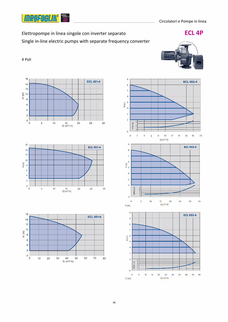
Elettropompe in linea singole con inverter separato ECL 4P
Single in-line electric pumps with separate frequency converter
4 Poli

Circolatori e Pompe in linea
39

Circolatori e Pompe in linea
40
Elettropompe in linea singole con inverter separato ECL 2P
Single in-line electric pumps with separate frequency converter
2 Poli

Circolatori e Pompe in linea
41
Dati tecnici e Dimensioni ECL 2P-4P
MODELLO DN Q: mc/h H: m PN T min. T Max IP
ECL 401 - 4 40 20 15 16 -15°C 140 54
ECL 402 - 4 40 18 8 16 -15°C 140 54
ECL 501 - 4 50 26 15 16 -15°C 140 54
ECL 502 - 4 50 29 8 16 -15°C 140 54
ECL 651 - 4 65 56 15 16 -15°C 140 54
ECL 652 - 4 65 47 8 16 -15°C 140 54
ECL 801 - 4 80 85 15 16 -15°C 140 54
ECL 802 - 4 80 85 9 16 -15°C 140 54
ECL 1001 - 4 100 119 15 16 -15°C 140 54
ECL 1002 - 4 100 100 9,5 16 -15°C 140 54
ECL 403 - 2 40 25 22 16 -15°C 140 54
ECL 503 - 2 50 50 20 16 -15°C 140 54
ECL 653 - 2 65 72 24 16 -15°C 140 54
ECL 803 – 2 80 100 22 16 -15°C 140 54
MODELLO L (mm) DN a f l1 l h1 h2 D1 D2 D3
ECL 401 - 4 390 40 90 155 234 479 190 200 150 110 18
ECL 402 - 4 360 40 90 155 234 479 180 180 150 110 18
ECL 501 - 4 425 50 96 159 249 504 205 220 165 125 18
ECL 502 - 4 380 50 96 159 249 504 180 200 165 125 18
ECL 651 - 4 480 65 95 164 249 508 225 255 185 145 18
ECL 652 - 4 420 65 95 164 249 508 200 220 185 145 18
ECL 801 - 4 530 80 103 168 307 578 245 285 200 160 18
ECL 802 - 4 480 80 103 168 307 578 220 260 200 160 18
ECL 1001 - 4 560 100 113 169 307 589 270 290 220 180 18
ECL 1002 - 4 520 100 113 169 307 589 245 275 220 180 18
ECL 403 - 2 340 40 90 155 314 559 160 180 150 110 18
ECL 503 - 2 340 50 96 159 314 569 160 180 165 125 18
ECL 653 - 2 390 65 95 189 361 645 180 210 185 145 18
ECL 803 – 2 440 80 103 193 357 653 200 240 200 160 18
MODELLO Pot. (W) In (A) V Classe
isolamento
MODELLO Pot. (W) In (A) V
Classe
isolamento
ECL 401 - 4 1100 2,4
3 ~ 400 V F
ECL 403 - 2 3000 5,92
3 ~ 400 V F
ECL 402 - 4 750 1,63 ECL 503 - 2 3000 5,92
ECL 501 - 4 1500 3,26 ECL 653 - 2 5500 10,6
ECL 502 - 4 1100 2,4 ECL 803 - 2 7500 14,1
ECL 651 - 4 2200 4,64 ECL 802 - 2 18500 33,7
ECL 652 - 4 1100 2,4 ECL 801 - 2 22000 39,1
ECL 653 - 4 750 4,63 ECL 652 - 2 7500 14,1
ECL 801 - 4 3000 6,17 ECL 651 - 2 15000 27,6
ECL 802 - 4 2200 4,64 ECL 502 - 2 5500 10,6
ECL 803 - 4 1100 2,4 ECL 402 - 2 4000 7,72
ECL 1001 - 4 4000 8,11 ECL 401 - 2 5500 10,6
ECL 1002 - 4 3000 6,17

Circolatori e Pompe in linea
42
Elettropompe singole in linea standard CV 2P-4P
Single standard In-line electric pumps
4 Poli 2 Poli
Dati tecnici e dimensioni
MODELLO DN PN T
min. T Max IP
rpm Pot.
(W) In (A) V
Classe
isolamento
CV 32 - 4 / 60
32 16 -10°C 110°C 54
1340 120 0,41
3~400V F
CV 32 - 4 / 70 1340 120 0,41
CV 32 - 4 / 80 1340 120 0,41
CV 32 - 2 / 60 2750 250 0,64
CV 32 - 2 / 70 2750 250 0,64
CV 32 - 2 / 80 2750 250 0,64

Circolatori e Pompe in linea
43
Elettropompe singole in linea standard CL 4P
Single standard In-line electric pumps
4 Poli

Circolatori e Pompe in linea
44
Elettropompe singole in linea standard CL 2P
Single standard In-line electric pumps
2 Poli

Circolatori e Pompe in linea
45
Elettropompe singole in linea standard CL 2P
Single standard In-line electric pumps
2 Poli

Circolatori e Pompe in linea
46

Circolatori e Pompe in linea
47

Circolatori e Pompe in linea
48
CL 4P Dati Tecnici 4 Poli – 1500 rpm
MODELLO Pot. (W) In (A) V Classe
isolamento
MODELLO Pot. (W) In (A) V
Classe
isolamento
CL 40-140/4 1100 2,4
3 ~ 400 V F
CL 80-100.1/4 1500 3,26
3 ~ 400 V F
CL 40-110/4 750 1,63 CL 80-100.2/4 2200 4,64
CL 40-90/4 550 1,27 CL 80-90/4 2200 4,64
CL 40-60/4 550 1,27 CL 80-80.1/4 1500 3,26
CL 50-140.1/4 1100 2,4 CL 80-80.2/4 2200 4,64
CL 50-140.2/4 1500 3,26 CL 80-60.1/4 750 1,63
CL 50-120.1/4 750 1,63 CL 80-60.2/4 1100 2,4
CL 50-120.2/4 1100 2,4 CL 80-60.3/4 1500 3,26
CL 50-110.1/4 750 1,63 CL 80-40.1/4 550 1,27
CL 50-110.2/4 1100 2,4 CL 80-40.2/4 750 1,63
CL 50-100/4 750 1,63 CL 100-140.1/4 3000 6,17
CL 50-90/4 550 1,27 CL 100-140.2/4 4000 8,11
CL 50-80/4 1100 2,4 CL 100-130.1/4 2200 4,64
CL 50-70/4 550 1,27 CL 100-130.2/4 3000 6,17
CL 50-50/4 550 1,27 CL 100-110/4 2200 4,64
CL 65-150/4 2200 4,64 CL 100-90/4 3000 6,17
CL 65-120/4 1500 3,26 CL 125-250/4W 5500 11
CL 65-90.1/4 750 1,63 CL 125-250/4Z 5500 11
CL 65-90.2/4 1100 2,4 CL 125-250/4Y 7500 15
CL 65-70/4 750 1,63 CL 125-250/4X 9200 19
CL 65-50/4 550 1,27 CL 150-250/4W 7500 15
CL 80-140.1/4 2200 4,64 CL 150-250/4V 9200 19
CL 80-140.2/4 3000 6,17 CL 150-250/4Z 11000 22
CL 80-120/4 2200 4,64 CL 150-250/4Y 15000 30
CL 80-110/4 2200 4,64 CL 150-250/4X 15000 30
CL 2P Dati Tecnici 2 Poli – 3000 rpm
MODELLO Pot. (W) In (A) V Classe
isolamento
MODELLO Pot. (W) In (A) V
Classe
isolamento
CL 401 - 2 5500 10,6
3 ~ 400 V F
CL 50-160/2B 3000 6
3 ~ 400 V F
CL 402 - 2 4000 7,72 CL 50-160/2A 4000 8
CL 403 - 2 3000 5,92 CL 50-200/2C 5500 11
CL 501 - 2 11000 20,4 CL 50-200/2B 6300 13
CL 502 - 2 5500 10,6 CL 50-200/2A 7500 15
CL 503 - 2 3000 5,92 CL 65-125/2C 2000 4
CL 651 - 2 15000 27,6 CL 65-125/2B 3000 6
CL 652 - 2 7500 14,1 CL 65-125/2A 4000 8
CL 653 - 2 5500 10,6 CL 65-160/2B 5500 11
CL 801 - 2 22000 39,1 CL 65-160/2A 7500 15
CL 802 - 2 18500 33,7 CL 65-200/2B 10000 20
CL 803 - 2 7500 14,1 CL 65-200/2A 12500 25
CL 32-100/2A 370 0,8 CL 80-160/2C 10000 20
CL 40-100/2B 550 1,1 CL 80-160/2B 12500 25
CL 40-100/2A 750 1,5 CL 80-160/2A 15000 30
CL 40-125/2C 750 1,5 CL 80-200/2D 15000 30
CL 40-125/2B 1000 2 CL 80-200/2C 18500 37
CL 40-125/2A 1500 3 CL 80-200/2B 22000 44
CL 40-160/2C 2000 4 CL 100-160/2D 10000 20
CL 40-160/2B 3000 6 CL 100-160/2C 12500 25
CL 40-160/2A 3000 6 CL 100-160/2B 15000 30
CL 40-200/2C 4000 8 CL 100-200/2D 18500 37
CL 40-200/2B 5500 11 CL 100-200/2C 22000 44
CL 40-200/2A 6300 13 CL 100-200/2B 30000 60
CL 50-125/2C 1500 3 CL 100-200/2A 37000 74
CL 50-125/2B 2000 4 CL 100-250/2D 37000 74
CL 50-125/2A 3000 6 CL 50-160/2B 18500 37

Circolatori e Pompe in linea
49
Elettropompe singole in linea standard
Single standard In-line electric pumps
4 Poli
CL 4P
Dimensioni (mm)
MODELLO L (mm) DN a/B f b1/E b2/F h1/l h2/H d h3 l1/C Pg l x
CL 40-140/4 390 40 90 163 145 135 190 200 200 138 249 16 502 100
CL 40-110/4 390 40 90 163 145 135 190 200 200 138 249 13,5 487 100
CL 40-90/4 360 40 90 155 133 127 180 180 200 130 234 13,5 479 100
CL 40-60/4 340 40 90 155 113 106 160 180 200 130 234 13,5 479 100
CL 50-140.1/4 425 50 96 159 150 135 205 220 200 138 274 16 512 100
CL 50-140.2/4 425 50 96 159 150 135 205 220 200 138 274 16 527 100
CL 50-120.1/4 425 50 96 159 150 135 205 220 200 138 274 13,5 489 100
CL 50-120.2/4 425 50 96 159 150 135 205 220 200 138 274 16 512 100
CL 50-110.1/4 425 50 96 159 150 135 205 220 200 138 274 13,5 489 100
CL 50-110.2/4 425 50 96 159 150 135 205 220 200 138 274 16 512 100
CL 50-100/4 425 50 96 159 150 135 205 220 200 138 274 13,5 489 100
CL 50-90/4 425 50 96 159 150 135 205 220 200 138 274 13,5 489 100
CL 50-80/4 380 50 96 159 138 126 180 200 200 138 249 16 512 100
CL 50-70/4 380 50 96 159 138 126 180 200 200 138 249 13,5 489 100
CL 50-50/4 340 50 96 159 240 107 160 180 200 130 234 13,5 489 100
CL 65-150/4 480 65 95 164 160 140 225 255 250 147 307 16 569 110
CL 65-120/4 480 65 95 164 160 140 225 255 250 147 307 16 531 110
CL 65-90.1/4 420 65 95 164 138 125 200 220 200 138 249 13,5 493 110
CL 65-90.2/4 420 65 95 164 138 125 200 220 200 138 249 16 516 110
CL 65-70/4 420 65 95 164 138 125 200 220 200 138 249 13,5 493 110
CL 65-50/4 390 65 95 164 135 110 180 210 200 130 234 13,5 493 110
CL 80-140.1/4 530 80 103 168 183 148 245 285 250 147 307 16 581 120
CL 80-140.2/4 530 80 103 168 183 148 245 285 250 147 307 16 581 120
CL 80-120/4 530 80 103 168 183 148 245 285 250 147 307 16 581 120
CL 80-110/4 530 80 103 168 183 148 245 285 250 147 307 16 581 120
CL 80-100.1/4 530 80 103 168 183 148 245 285 250 147 307 16 543 120
CL 80-100.2/4 530 80 103 168 183 148 245 285 250 147 307 16 581 120
CL 80-90/4 480 80 103 168 172 138 220 260 250 157 310 16 581 120
CL 80-80.1/4 480 80 103 168 172 138 220 260 250 147 307 16 543 120
CL 80-80.2/4 480 80 103 168 172 138 220 260 250 147 307 16 581 120
CL 80-60.1/4 440 80 103 168 158 124 200 240 200 138 249 13,5 505 120
CL 80-60.2/4 440 80 103 168 158 124 200 240 200 138 249 16 528 120
CL 80-60.3/4 440 80 103 168 185 124 200 240 200 121 272 16 543 120
CL 80-40.1/4 440 80 103 168 158 124 200 240 200 138 249 13,5 505 120
CL 80-40.2/4 440 80 103 168 158 124 200 240 200 138 249 13,5 505 120
CL 100-140.1/4 560 100 113 169 187 152 270 290 250 162 320 16 592 125
CL 100-140.2/4 560 100 113 169 187 152 270 290 250 162 320 16 602 125
CL 100-130.1/4 560 100 113 169 187 152 270 290 250 162 320 16 592 125
CL 100-130.2/4 560 100 113 169 187 152 270 290 250 162 320 16 592 125
CL 100-110/4 560 100 113 169 187 152 270 290 250 162 320 16 592 125
CL 100-90/4 520 100 113 169 180 140 245 275 250 147 307 16 592 125
CL 125-250/4W 620 125 195 195 195 280 340 550
CL 125-250/4Z 620 125 195 195 195 280 340 550
CL 125-250/4Y 620 125 195 195 195 280 340 550
CL 125-250/4X 620 125 195 195 195 280 340 550
CL 150-250/4W 700 150 220 210 210 330 370 555
CL 150-250/4V 700 150 220 210 210 330 370 555
CL 150-250/4Z 700 150 220 210 210 330 370 555
CL 150-250/4Y 700 150 220 210 210 330 370 755
CL 150-250/4X 700 150 220 210 210 330 370 755

Circolatori e Pompe in linea
50
Elettropompe singole in linea standard
Single standard In-line electric pumps
2 Poli
CL 2P Dimensioni (mm)
MODELLO L (mm) DN a/B f b1/E b2/F h1/l h2/H d h3 l1/C Pg l x
CL 401 - 2 390 40 90 188 145 135 190 200 300 200 361 21 639 100
CL 402 - 2 360 40 90 155 133 127 180 180 250 162 314 16 559 100
CL 403 - 2 340 40 90 155 113 106 160 180 250 147 314 16 559 100
CL 501 - 2 425 50 96 214 150 135 205 220 350 236 479 29 789 100
CL 502 - 2 380 50 96 184 138 126 180 200 300 200 361 21 641 100
CL 503 -2 340 50 96 159 124 107 160 180 250 147 314 16 569 100
CL 651 -2 480 65 95 219 160 140 225 255 350 236 521 29 835 110
CL 652 -2 420 65 95 189 138 125 200 220 300 200 361 21 611 110
CL 653 - 2 390 65 95 189 135 110 180 210 300 200 361 21 611 110
CL 801 -2 530 80 103 223 183 148 245 285 350 235 550 29 876 120
CL 802 - 2 480 80 103 223 172 138 225 255 350 236 521 29 847 120
CL 803 - 2 440 80 103 193 158 124 200 240 300 200 357 21 653 120
CL 32-100/2A 220 65 65 65 107 110 110 330
CL 40-100/2B 240 65 75 77 107 110 130 330
CL 40-100/2A 240 65 75 77 107 110 130 330
CL 40-125/2C 300 65 100 93 107 140 160 325
CL 40-125/2B 300 65 100 93 118 140 160 345
CL 40-125/2A 300 65 100 93 118 140 160 345
CL 40-160/2C 320 80 100 108 149 150 170 385
CL 40-160/2B 320 80 100 108 149 150 170 385
CL 40-160/2A 320 80 100 108 149 150 170 385
CL 40-200/2C 380 80 100 127 159 180 200 425
CL 40-200/2B 380 80 100 127 159 180 200 425
CL 40-200/2A 380 80 100 127 159 180 200 425
CL 50-125/2C 320 80 110 103 118 140 180 345
CL 50-125/2B 320 80 110 103 118 140 180 345
CL 50-125/2A 320 80 110 103 118 140 180 385
CL 50-160/2B 340 80 110 113 149 160 180 385
CL 50-160/2A 340 80 110 113 149 160 180 385
CL 50-200/2C 400 80 110 131 159 180 220 435
CL 50-200/2B 400 100 110 131 159 180 220 435
CL 50-200/2A 400 100 110 131 184 180 220 540
CL 65-125/2C 360 100 140 108 149 155 205 385
CL 65-125/2B 360 100 140 108 149 155 205 385
CL 65-125/2A 360 100 140 108 159 155 205 425
CL 65-160/2B 400 100 140 122 159 180 220 435
CL 65-160/2A 400 125 140 122 184 180 220 540
CL 65-200/2B 440 125 140 136 184 200 240 540
CL 65-200/2A 440 125 140 136 184 200 240 540
CL 80-160/2C 440 125 160 131 184 200 240 540
CL 80-160/2B 440 150 160 131 184 200 240 540
CL 80-160/2A 440 150 160 131 184 200 240 540
CL 80-200/2D 500 150 160 146 184 225 275 540
CL 80-200/2C 500 150 160 146 229 225 275 700
CL 80-200/2B 500 150 160 146 229 225 275 700
CL 100-160/2D 525 100 190 136 184 225 300 540
CL 100-160/2C 525 100 190 136 184 225 300 540
CL 100-160/2B 525 100 190 136 184 225 300 540
CL 100-200/2D 550 100 190 156 230 250 300 700
CL 100-200/2C 550 100 190 156 257 250 300 805
CL 100-200/2B 550 100 190 156 257 250 300 805
CL 100-200/2A 570 100 190 176 257 250 320 805
CL 100-250/2D 580 100 190 156 230 280 300 700

Circolatori e Pompe in linea
51
Elettropompe gemellari in linea standard CLD 4P
Double standard In-line electric pumps
4 Poli

Circolatori e Pompe in linea
52
Elettropompe gemellari in linea standard CLD 2P
Double standard In-line electric pumps
2 Poli

Circolatori e Pompe in linea
53
CLD 4P Dati Tecnici 4 Poli – 1500 rpm
MODELLO Pot. (W) In (A) V Classe
isolamento
CLD 40-125 /4Z 250 0,5
3 ~ 400 V F
CLD 40-125 /4Y 250 0,5
CLD 40-125 /4X 250 0,5
CLD 50-125 /4Y 250 0,5
CLD 50-125 /4X 370 0,8
CLD 50-160 /4X 500 1
CLD 65-160 /4Z 550 1,1
CLD 65-160 /4Y 750 1,5
CLD 65-160 /4X 900 1,8
CLD 80-160 /4W 750 1,5
CLD 80-160 /4Z 900 1,8
CLD 80-160 /4Y 1100 2,2
CLD 80-160 /4X 1500 3
CLD 100-200 /4W 1500 3
CLD 100-200 /4Z 2200 4,4
CLD 100-200 /4Y 3000 6
CLD 100-200 /4X 4000 8
CLD 2P Dati Tecnici 2 Poli – 3000 rpm
MODELLO Pot. (W) In (A) V Classe
isolamento
CLD 40-125/2D 550 1,1
3 ~ 400 V F
CLD 40-125/2C 750 1,5
CLD 40-125/2B 1000 2
CLD 40-125/2A 1500 3
CLD 50-125/2C 1500 3
CLD 50-125/2B 2000 4
CLD 50-125/2A 3000 6
CLD 50-160/2B 3000 6
CLD 50-160/2A 4000 8
CLD 65-160/2D 3000 6
CLD 65-160/2C 4000 8
CLD 65-160/2B 5500 11
CLD 65-160/2A 7500 15
CLD 80-160/2D 7500 15
CLD 80-160/2C 10000 20
CLD 80-160/2B 12500 25
CLD 80-160/2A 15000 30
CLD 100-200/2F 12500 25
CLD 100-200/2E 15000 30
CLD 100-200/2D 10000 20
CLD 100-200/2C 12500 25
CLD 100-200/2B 15000 30
CLD 100-200/2A 15000 30

Circolatori e Pompe in linea
54
Elettropompe gemellari in linea standard
Doble standard In-line electric pumps
2 Poli – 4 Poli
CLD 4P
CLD 2P
Dimensioni (mm)
MODELLO DN A B C D E F G H I L M
CLD 40-125 /4Z 40 425 100 345 397 200 197 340 130 210 20 100
CLD 40-125 /4Y 40 425 100 345 397 200 197 340 130 210 20 100
CLD 40-125 /4X 40 425 100 345 397 200 197 340 130 210 20 100
CLD 50-125 /4Y 50 435 110 325 427 217 210 365 145 220 22 105
CLD 50-125 /4X 50 435 110 325 427 217 210 365 145 220 22 105
CLD 50-160 /4X 50 435 110 325 480 245 235 410 170 240 22 120
CLD 65-160 /4Z 65 475 130 345 543 275 268 450 180 270 22 140
CLD 65-160 /4Y 65 475 130 345 543 275 268 450 180 270 22 140
CLD 65-160 /4X 65 475 130 345 543 275 268 450 180 270 22 140
CLD 80-160 /4W 80 485 150 385 550 280 270 510 205 305 24 135
CLD 80-160 /4Z 80 485 150 385 550 280 270 510 205 305 24 135
CLD 80-160 /4Y 80 535 150 385 550 280 270 510 205 305 24 135
CLD 80-160 /4X 80 535 150 385 550 280 270 510 205 305 24 135
CLD 100-200 /4W 100 535 180 435 670 325 345 630 240 390 26 165
CLD 100-200 /4Z 100 615 180 435 670 325 345 630 240 390 26 165
CLD 100-200 /4Y 100 615 180 435 670 325 345 630 240 390 26 165
CLD 100-200 /4X 100 615 180 435 670 325 345 630 240 390 26 165
CLD 40-125/2D 40 445 100 345 397 200 197 340 130 210 20 100
CLD 40-125/2C 40 445 100 345 397 200 197 340 130 210 20 100
CLD 40-125/2B 40 425 100 345 397 200 197 340 130 210 20 100
CLD 40-125/2A 40 425 100 345 397 200 197 340 130 210 20 100
CLD 50-125/2C 50 495 110 385 427 217 210 365 145 220 22 105
CLD 50-125/2B 50 495 110 385 427 217 210 365 145 220 22 105
CLD 50-125/2A 50 495 110 385 427 217 210 365 145 220 22 105
CLD 50-160/2B 50 495 110 385 480 245 235 410 170 240 22 120
CLD 50-160/2A 50 535 110 425 480 245 235 410 170 240 22 120
CLD 65-160/2D 65 515 130 385 543 275 268 450 180 270 22 140
CLD 65-160/2C 65 565 130 435 543 275 268 450 180 270 22 140
CLD 65-160/2B 65 565 130 435 543 275 268 450 180 270 22 140
CLD 65-160/2A 65 670 130 540 543 275 268 450 180 270 22 140
CLD 80-160/2D 80 640 150 540 550 280 270 510 205 305 24 135
CLD 80-160/2C 80 690 150 540 550 280 270 510 205 305 24 135
CLD 80-160/2B 80 690 150 540 550 280 270 510 205 305 24 135
CLD 80-160/2A 80 690 150 540 550 280 270 510 205 305 24 135
CLD 100-200/2F 100 720 180 540 670 325 345 630 240 390 26 165
CLD 100-200/2E 100 720 180 540 670 325 345 630 240 390 26 165
CLD 100-200/2D 100 720 180 540 670 325 345 630 240 390 26 165
CLD 100-200/2C 100 720 180 540 670 325 345 630 240 390 26 165
CLD 100-200/2B 100 720 180 540 670 325 345 630 240 390 26 165
CLD 100-200/2A 100 720 180 540 670 325 345 630 240 390 26 165

CATALOGO TECNICO TECHNICAL CATALOGUE
MEMBER OF
Edition May 2014
IDROFOGLIA srl
Via Provinciale, 14 / 61026 Lunano (PU) Italy
phone +39 0722.700311 / fax +39 0722.700309
www.idrofogliasafety.com / [email protected]