CIGUI32 User Manual - Repeater Builder
177
Revision F October 2001 Copyright 1997-2001 by California Instruments All rights reserved P/N 7000-988 CIGUI32 iX-Series, i-Series iL-Series, HGA Graphical User Interface Software User’s Manual Version 1.09 For use with Software P/N: CIC 475 TEL: +1 (858) 677-9040 FAX: +1 (858) 677-0940 Email: [email protected] Web Site: http://www.calinst.com
Transcript of CIGUI32 User Manual - Repeater Builder

Revision FOctober 2001
Copyright 1997-2001by California Instruments
All rights reservedP/N 7000-988
CIGUI32iX-Series, i-Series
iL-Series, HGAGraphical User Interface
Software User’s Manual
Version 1.09
For use with Software P/N: CIC 475
TEL: +1 (858) 677-9040FAX: +1 (858) 677-0940
Email: [email protected] Site: http://www.calinst.com

CIGUI32 Software User’s Manual
2
(This page intentionally left blank)

CIGUI32 Software User’s Manual
3
LIMITED WARRANTY
California Instruments believes the information contained in this manual is accurate. This document hasbeen carefully reviewed for technical accuracy. In the event that technical or typographical errors exist,California Instruments reserves the right to make changes to subsequent editions of this document withoutprior notice to holders of this edition. The reader should consult California Instruments if errors aresuspected. In no event shall California Instruments be liable for any damages arising out of or related to thisdocument or the information contained in it.
CALIFORNIA INSTRUMENTS PROVIDES NO WARRANTIES, EXPRESS OR IMPLIED, ANDSPECIFICALLY DISCLAIMS ANY WARRANTY OF MERCHANTABILITY OR FITNESS FOR A PARTICULARPURPOSE OF THIS SOFTWARE AND DOCUMENTATION. CALIFORNIA INSTRUMENTS WILL NOT BELIABLE FOR DAMAGES RESULTING FROM LOSS OF DATA, PROFITS, USE OF PRODUCTS, ORINCIDENTAL OR CONSEQUENTIAL DAMAGES, EVEN IF ADVISED OF THE POSSIBILITY THEREOF.This limitation of liability of California Instruments will apply regardless of the form of action, whether incontract or tort, including negligence. The warranty provided herein does not cover damages, defects,malfunctions, or service failures caused by owner’s failure to follow California Instruments’ installation,operation, or maintenance instructions; owner’s modification of the product; owner’s abuse, misuse, ornegligent acts; and power failures, surges, fire, flood, accident, actions of third parties, or other eventsoutside reasonable control.SOME STATES DO NOT ALLOW LIMITATIONS ON THE LENGTH OF AN IMPLIED WARRANTY OR THEEXCLUSION OR LIMITATION OF INCIDENTAL OR CONSEQUENTIAL DAMAGES, SO THE ABOVELIMITATION OR EXCLUSIONS MAY NOT APPLY TO YOU. THIS WARRANTY GIVES YOU SPECIFICLEGAL RIGHTS, AND YOU MAY ALSO HAVE OTHER RIGHTS WHICH VARY FROM STATE TO STATE.If any part of this Agreement shall be determined by a court to be invalid, illegal or unenforceable, theremaining provisions shall in no way be affected or impaired thereby.GOVERNING LAW. This Agreement and Limited Warranty are governed by the laws of the state ofCalifornia without regard to conflict of law provisions.
INSTALLATION AND / OR USE OF THIS PROGRAM CONSTITUTES ACCEPTANCE OF THESE TERMSAND RESTRICTIONS BY THE USER.
COPYRIGHT © 1997-2001Under the copyright laws, this publication may not be reproduced or transmitted in any form, electronic ormechanical, including photocopying, recording, storing in an information retrieval system, or translating, inwhole or in part, without the prior written consent of California Instruments Corporation.
California Instruments Corporation, © 1997 - 2001
Warning regarding Medical and Clinical use of CaliforniaInstruments products.
California Instruments products are not designed with components and testing intended to ensure a level ofreliability suitable for use in the treatment and diagnosis of human beings. California Instruments productsare NOT intended to be used to monitor or safeguard human health and safety in medical or clinicaltreatment and California Instruments assumes no responsibility for this type of use of its products orsoftware.

CIGUI32 Software User’s Manual
4
(This page intentionally left blank)

CIGUI32 Software User’s Manual
5
Table of Contents
1 Introduction ............................................................................................................................................91.1 About This Program .....................................................................................................................................................91.2 About This Manual........................................................................................................................................................91.3 Software Version........................................................................................................................................................101.4 Program Requirements..............................................................................................................................................111.5 RS232C Cable Wiring ...............................................................................................................................................12
2 Setup and Installation...........................................................................................................................132.1 Connecting the AC Source to PC .............................................................................................................................132.2 Installing the CIGUI32 Software................................................................................................................................132.3 Software Registration.................................................................................................................................................14
3 User Interface Aspects.........................................................................................................................153.1 Starting the CIGUI32..................................................................................................................................................153.2 Command Line Options .............................................................................................................................................163.3 Main Program Window...............................................................................................................................................173.4 Menu Structure............................................................................................................................................................183.5 Selecting Menu Items With the Mouse .....................................................................................................................253.6 Selecting Menu Items Using the Keyboard ..............................................................................................................253.7 Using the Toolbar .......................................................................................................................................................253.8 Status Bar....................................................................................................................................................................273.9 Modal and Non-Modal Windows................................................................................................................................27
4 AC Source Control ...............................................................................................................................284.1 Steady State Front Panel...........................................................................................................................................284.2 Model Number Selection Window.............................................................................................................................334.3 Configuration and User Limits Settings Window......................................................................................................344.4 Interface Window .......................................................................................................................................................364.5 Power-on Settings......................................................................................................................................................374.6 Interharmonics Generator Control.............................................................................................................................38
5 Transients ............................................................................................................................................405.1 Transient Data Entry...................................................................................................................................................415.2 Error Checking............................................................................................................................................................445.3 DC Transients.............................................................................................................................................................445.4 Triggering Waveform Acquisitions............................................................................................................................455.5 Transient Types..........................................................................................................................................................465.6 Transient Phase Selection.........................................................................................................................................565.7 Executing Transient Lists...........................................................................................................................................575.8 Managing Multiple Transient Programs.....................................................................................................................595.9 Transient Editor Control Window...............................................................................................................................62
6 Waveform Generation..........................................................................................................................666.1 Creating Harmonic Waveforms .................................................................................................................................676.2 Creating Arbitrary Waveforms ...................................................................................................................................69
7 Measurements .....................................................................................................................................747.1 Standard Measurements............................................................................................................................................757.2 Harmonic Measurements ...........................................................................................................................................777.3 Harmonic Limit Testing ..............................................................................................................................................807.4 Waveform Measurements .........................................................................................................................................847.5 Data Logging ..............................................................................................................................................................887.6 Using a Spreadsheet Program ..................................................................................................................................94
8 Applications..........................................................................................................................................958.1 MIL-STD-704..............................................................................................................................................................96

CIGUI32 Software User’s Manual
6
8.2 RTCA/DO-160..........................................................................................................................................................1008.3 EN/IEC 61000-4-11 for i/iX Series with –411 and/or EOS Option only ...............................................................1038.4 EN/IEC 61000-4-11 for All Other AC Source Models ...........................................................................................1068.5 EN/IEC 61000-4-13 Harmonics and Interharmonics Immunity Test ....................................................................1138.6 EN/IEC 61000-4-14 Voltage Fluctuations Immunity Test .....................................................................................1238.7 EN/IEC 61000-4-17 DC Ripple Immunity Test......................................................................................................1288.8 EN/IEC 61000-4-27p Voltage Unbalance Immunity Testing ................................................................................1328.9 EN/IEC 61000-4-28 Frequency Variations Immunity Test....................................................................................1388.10 EN/IEC 61000-4-29 DC Dips and Interruptions Immunity Test (Pre-compliance).........................................143
9 Calibration..........................................................................................................................................1509.1 Calibration Support Features...................................................................................................................................1509.2 Calibration Password ...............................................................................................................................................1509.3 Output Calibration.....................................................................................................................................................1519.4 Measurement Calibration.........................................................................................................................................1559.5 Output Impedance Calibration [iX Series only].......................................................................................................1599.6 Calibration Reports...................................................................................................................................................1609.7 Calibration Output Check.........................................................................................................................................163
10 Managing AC Source Hardware Configuration Data .........................................................................16410.1 Configuration Data...............................................................................................................................................16410.2 User Limits ...........................................................................................................................................................16510.3 i/iX Series Clock Mode........................................................................................................................................16510.4 i/iX Series Output Impedance ............................................................................................................................165
11 File Formats.....................................................................................................................................16611.1 Steady State Setup Files (.stp)...........................................................................................................................16711.2 Transient Program Files (.tls) .............................................................................................................................16811.3 CSV Data Files. (.csv).........................................................................................................................................16911.4 Harmonic Measurement Data Files (.hmd)........................................................................................................16911.5 Waveform Measurement Data Files (.wvd) .......................................................................................................16911.6 Harmonic Waveform Files (.hwd).......................................................................................................................17011.7 Arbitrary Waveform Files (.abw).........................................................................................................................170
12 Troubleshooting................................................................................................................................17212.1 Interface Problems..............................................................................................................................................17212.2 Constant or Frequent Syntax Error Messages ..................................................................................................17312.3 RS232C Problems..............................................................................................................................................17312.4 Configuration Errors ............................................................................................................................................17412.5 Parameter Conflicts.............................................................................................................................................17512.6 Problems Not Listed ...........................................................................................................................................17512.7 Problem Report Forms.......................................................................................................................................175
13 Index................................................................................................................................................176

CIGUI32 Software User’s Manual
7
Table of FiguresFigure 1-1 : RS232C Cable Wiring ..........................................................................................................................................12Figure 3-1 : CIGUI32 Main Program Window .........................................................................................................................17Figure 4-1 : Model Number Selection Windows .....................................................................................................................33Figure 4-2 : Interface Settings..................................................................................................................................................36Figure 4-3 : Power On Settings................................................................................................................................................37Figure 5-1 : Voltage Drop Transient.........................................................................................................................................47Figure 5-2 : Voltage Step Transient .........................................................................................................................................48Figure 5-3 : Voltage Surge/Sag Transient ...............................................................................................................................49Figure 5-4 : Voltage Sweep Transient .....................................................................................................................................50Figure 5-5 : Frequency Step Transient ....................................................................................................................................51Figure 5-6 : Frequency Surge/Sag Transient ..........................................................................................................................52Figure 5-7 : Frequency Sweep Transient ................................................................................................................................53Figure 5-8 : Voltage and Frequency Step Transient...............................................................................................................54Figure 5-9 : Voltage and Frequency Sweep Transient ...........................................................................................................55Figure 5-10: Transient List Editor Control Window.................................................................................................................62Figure 6-1: Harmonic Waveform Generation Window............................................................................................................67Figure 7-1 : Measurement Window..........................................................................................................................................74Figure 7-2 : Harmonic Measurement Window.........................................................................................................................77Figure 7-3 : Harmonic Limit Test Window ...............................................................................................................................80Figure 7-4: Timing Waveform Window....................................................................................................................................84Figure 7-5 : Measurement Log File Setup Window................................................................................................................88Figure 7-6 : Sample Spreadsheet of Measurement Data.......................................................................................................94Figure 8-1: MIL-STD 704 Test Window ..................................................................................................................................96Figure 8-2: RTCA/DO-160D Test Window ...........................................................................................................................100Figure 8-3: IEC 61000-4-11 i/iX Series –411 Option Test window.....................................................................................103Figure 8-4: IEC 61000-4-11 Test window.............................................................................................................................106Figure 8-5: IEC 61000-4-11 Voltage Variation specification...............................................................................................107Figure 8-6 : IEC 61000-4-13 Test Window...........................................................................................................................113Figure 8-7: IEC 61000-4-13 Test Fow..................................................................................................................................114Figure 8-8: IEC 61000-4-13 Test Waveforms......................................................................................................................117Figure 8-9: IEC 61000-4-13 Voltage Distortion Display.......................................................................................................119Figure 8-10: IEC 61000-4-13 Waveform Acquisition Display .............................................................................................120Figure 8-11: IEC 61000-4-13 Resonance Data display.......................................................................................................121Figure 8-12: IEC 61000-4-14 Test window...........................................................................................................................123Figure 8-13: IEC 61000-4-14 Voltage fluctuation specification...........................................................................................124Figure 8-14: IEC 61000-4-17 DC Ripple Test Window.......................................................................................................128Figure 8-15: IEC 61000-4-17 Waveform Acquisition Window............................................................................................130Figure 8-16: IEC 61000-4-17 User Observation Data Entry Window .................................................................................131Figure 17: EN61000-4-27 Test Window ...............................................................................................................................132Figure 8-18: IEC 61000-4-28 Test window...........................................................................................................................138Figure 8:19: EN61000-4-28 Test Sequence ........................................................................................................................139Figure 8-20: IEC 61000-4-29 Test window...........................................................................................................................143Figure 9-1 : iL Series Output Calibration Window.................................................................................................................152Figure 9-2 : iL Series Current Output Calibration..................................................................................................................152Figure 9-3 : i Series Output Calibration Window...................................................................................................................153Figure 9-4 : HGA Output Calibration Window........................................................................................................................154Figure 9-5 : iL Series Measurement Calibration Window.....................................................................................................155Figure 9-6 : i Series Measurement Calibration Window .......................................................................................................156Figure 9-7 : iX Series Measurement Calibration Window.....................................................................................................157Figure 9-8 : HGA Measurement Calibration Window............................................................................................................158Figure 9-9: i Series Calibration report ....................................................................................................................................160Figure 9-10 : iX Series Calibration Report Window..............................................................................................................161Figure 9-11: HGA Calibration report ......................................................................................................................................162Figure 9-12 : Output calibration check window......................................................................................................................163

CIGUI32 Software User’s Manual
8
Figure 10-1 : AC Source Configuration Window...................................................................................................................164Figure 12-1 : Recommended RS232C port FIFO settings .................................................................................................174
List of TablesTable 5-1 : Available Transient List Events .............................................................................................................................46Table 5-2 : Transient List Size by Model .................................................................................................................................57Table 5-3: Transient List Editor Control Window Functions ...................................................................................................63Table 5-4: Transient List Editor Restrictions ...........................................................................................................................64Table 7-1 : Standard Measurement Data Log File Format.....................................................................................................90Table 7-2 : Harmonic Measurement Data Log File Format ....................................................................................................91Table 8-1: MIL-STD 704 Steady State Settings .....................................................................................................................97Table 8-2: MIL-STD 704 Test Times.......................................................................................................................................98Table 8-3: IEC 61000-4-13 Test Types................................................................................................................................114Table 8-4: IEC 61000-4-13 Test Times................................................................................................................................115Table 8-5: IEC 61000-4-13 Control Tabs .............................................................................................................................115Table 8-6: IEC 61000-4-13 Test Setup Parameters ............................................................................................................116Table 8-7: IEC 61000-4-13 Min and Max Test Times ..........................................................................................................118Table 8: EN61000-4-14 Test Sequence ..............................................................................................................................125Table 11-1 : Steady State Setup File Format........................................................................................................................167Table 11-2 : Transient Program File Format .........................................................................................................................168Table 11-3 : Harmonic Measurement Data File Format........................................................................................................169Table 11-4 : Waveform Measurement Data File Format......................................................................................................169Table 11-5 : Harmonic Waveform File Format......................................................................................................................170Table 11-6 : Arbitrary Waveform File Format........................................................................................................................170

CIGUI32 Software User’s Manual
9
1 Introduction
1.1 About This Program
The California Instruments Graphical User Interface program (CIGUI32) was developedas a companion product to the California Instrument line of AC power sources. It’s mainpurpose is to provide a soft front panel to the instrument when connected to a PC throughthe IEEE-488 bus or RS232C serial interface. Additional benefits are obtained from usingthe PC as a control interface. Some of these benefits include the ability to storemeasurement data to disk and interact with other programs.
The CIGUI32 is a 32 bit Windows program and as such requires a PC capable ofrunning Windows 95™, Windows 98™, Windows NT™ or Windows 2000™. For bestperformance a Pentium class PC is recommended.
This user manual provides a complete overview of the program’s operation. It also listsdetails on file formats and other information that may be needed in order to use this programsuccessfully. Extensive information can also be found in the on-line help supplied with theprogram. Use the Help menu or press on any of the many Help keys located in all programwindows for an explanation of the relevant window or function.
As always, California Instruments appreciates your patronage and would welcome anycomments and suggestions you might have regarding this software or any of its otherproducts. Use the customer feedback form located in the back of this manual. The sameform can be used to report software bugs should you encounter any.
1.2 About This Manual
This manual covers the operation of the CIGUI32 software version 1.00 or higher. It isstrongly recommended that you familiarize yourself with the operation of the actual ACpower source as well. This is best done by studying the instruction manual supplied with theAC source. The CIGUI32 supports all models in the i Series, iX Series, iL Series and HGASeries.

CIGUI32 Software User’s Manual
10
1.3 Software Version
This manual covers software version 1.08. From time to time, it may be necessary torelease a new version of the CIGUI32 software to fix bugs and or add new features andcapabilities. This will result in the decimal portion of the version number being increased. Inthis case, it is unlikely that a new user manual would be required. Addendum’s and changesto this manual will be provided in the form of a readme.txt file on the distribution disk. Assuch, you will not normally receive an new manual when you receive a new softwareversion. Major changes to the functionality or operation of this software may require a newmanual version as well. In this case, the integer version number part will be increased and anew manual version will be issued.
If the CIGUI32 software version you are using is 1.XX with XX from 00 to 99, continueto use this manual. If the version number is 2.00 or higher, contact California Instruments toobtain an updated manual. Production and shipping charges will apply.
Manual revision : F
Release date: October, 2001
1.3.1 New Features in Version 1.07
The following model series are supported:
• iX Series• iL Series• i Series• HGA controller
• The EN/ IEC 61000-4-27 voltage unbalance immunity test has been added to thisrelease. This capability is only supported on three phase iX Series systems. (9003iX,15003iX and 30003iX).
• Sample rate used for acquiring waveform data can be set in 25 usec (single-phase iXmodels) or 75 usec (3 phase iX models) steps between 25 and 250 usec or 75 and 750usec.
• For additional bug fixes and added functions, consult the readme.txt file installed withthe program.
1.3.2 New Features in Version 1.08
• The allowable dwell time that can be programmed from the transient screen for i/iX andiL Series power sources has been increased from 999 sec to 90,000 sec.
• Voltage and frequency slew rate resolution on iX Series with firmware revision 2.22 orhigher has been extended from 0.1 V/sec and 0.1 Hz/sec to 0.001 V/s and 0.001 Hz/secto allow longer duration transient sweeps to be programmed. These extended resolutionslew rates are now supported by rev 1.08.If this GUI version is used with older firmware revisions, a -222 Data out of Range errormay be generated by the power source when the CIGUI32 tries to program a slew rateless than 0.1 V/sec or 0.1 Hz/sec.
• A Graph Display clear menu entry has been added to the Timing Measurementwaveform display window. This entry allows the graph display to be cleared.
• Test report generation capability has been added to the RTCA/DO-160 (-160) and Mil-Std-704 (-704) test windows.

CIGUI32 Software User’s Manual
11
1.3.3 New Features in Version 1.09
• Added amplitude adjustment in IEC417 for voltages above ±10Vdc to improve outputaccuracy when using AC+DC mode and special DC level arb waveforms.
• Updated DO160 test window to support EUROCAE and Airbus modes.
• All IEC, DO160 and 704 test windows now allow entry of Test Site, Ambient Temp andPressure. This data is also incorporated in the test reports.
• Added setup save and recall to disk to DO160 and 704 Test windows.
• Added Abort command to 413 Stop button. Unless 413 test in progress is aborted, theIEC413:STAT OFF command won't be accepted and the TRACE subsystem is disabledwhile 413 state is on. This would lead to query error and invalid property errors insteady state query.
• Change saving of user limits to Integer format to avoid problems when switchinginternational settings in Windows.
• Added support for class1 to IEC413. Class1 is implemented using User class onfirmware so no firmware changes needed to add class 1 for existing users.
• Modified IEC414 screen to implement new 100 % Nominal sequence and add pre-testdelay at x % of Unom before starting voltage variations.
1.4 Program Requirements
To successfully install and operate the CIGUI32 program, you will need the followingequipment :
California Instruments AC power source.
Supported models are :
• All iL Series power source analyzer combinations
• All i Series AC and DC power sources with programmable controllers
• All iX Series AC and DC power sources with programmable controllers
• All AC power sources controlled by the Harmonic Generation and Analyzer externalcontroller (HGA).
PC Configuration.
• PC capable of running Windows98™, Windows ME™ or Windows NT4/2000™
• National Instruments PC/IIA or PC-AT/TNT IEEE interface card. Other vendor IEEEinterface cards are not supported unless they are compatible at the DLL level1. Notethat the 32 bit GPIB NI drivers are required to run the CIGUI32.
or
• RS232C communications port
• IEEE Cable (not supplied by California Instruments)
or
1 DLL compatibility implies identical function calls and parameters as the National Instruments GPIB32.DLL.

CIGUI32 Software User’s Manual
12
• RS232C serial cable (supplied with the AC power source.) See next section of RS232Ccable wiring
Note: The CIGUI32 can be run in the absence of a power source. If no AC source is available,the CIGUI32 can be operated in a simulation mode. The program will detect theseconditions and start up in simulation mode after notifying the operator. Measurements in thiscase will be simulated and should not be used for any analytical purpose.
1.5 RS232C Cable Wiring
California Instruments AC power sources require a special RS232C cable tocommunicate with a PC. Standard null-modem cables obtained from a computer hardwarestore most likely will not work. For this reason, all California Instruments power sources thatoperate over RS232C are supplied with a RS232C 9 pin female to 9 pin female cable.
If for some reason this cable cannot be located, the following cable the diagram shownin Figure 1-1 should be used when constructing a serial cable.
Figure 1-1 : RS232C Cable Wiring
DB-9 PC DB-9 AC Source
Pin1
2
34
56
78
9
Pin1
2
34
56
78
9
Directionoutput
input
outputoutput
-input
--
output
Descriptionreserved
Receive data(RxD)
Transmit data (TxD)Data Terminal Ready (DTR)
Signal GroundData Set Ready (DSR)
no connectno connect
reserved
Note: This cable is not bi-directional so it is important to mark the PC side and the AC source sideof this cable. If the cable is connected in reverse, it will not operate correctly.

CIGUI32 Software User’s Manual
13
2 Setup and Installation
This section covers installation of the CIGUI32 from the distribution disk to the user’sPC. Make sure the PC is capable of running Windows 98/NT/2000™ with at least 32Mbytes of memory and 5 Mbytes of available hard disk space.
2.1 Connecting the AC Source to PC
Connect the AC source to the PC using a suitable IEEE interface or RS232C cabledepending on the interface you plan to use. Make sure you screw down the IEEEconnectors securely or they will not make good contact. The IEEE address used by thepower source is retained in non volatile memory. Factory setting is normally 1 but thisaddress may have been changed from the front panel.
If RS232C will be used, make sure the AC source com port settings are set as follows:
Baud rate: 9600 baud for HGA and iL Series, 9600 to 38400 for i/iX Series
Data bits: 8
Stop bits 2 for use with iL Series AC source
1 for use with i/iX Series or HGA
Parity bits: none
2.2 Installing the CIGUI32 Software
The CIGUI32 software is distributed on CD-ROM or may be downloaded from theCalifornia Instruments’ web site. Downloaded installation files may be password protectedto control distribution to legitimate California Instruments customers only. If you obtainedthis program by downloading it, you will have to submit information on the model and serialnumber of the AC source used. Once this information has been verified, the installationpassword will be emailed to you.
The GUI must be installed from this CD ROM or the self extracting installation file as allrequired files are distributed in compressed form. You cannot copy the contents of this CD-ROM to your PC hard drive and run it. To install the CIGUI32 from the CD-ROM, proceedas follows:
1. Turn on the PC and boot up in Windows™.
2. Insert the CIGUI32 CD-ROM in your CD-ROM drive
3. Form the Start menu, select Run.
4. Type in “setup” without the quotation marks and click on the OK button.
5. From the list of available power source models, select (click on entry with the mouse)the model or series of the product you purchased.
6. Once the correct product has been selected, select the GUI Software Tab on the righthand side. Select the correct operating system (typically 32 bit) and click on the"Execute Selection" button at the bottom of the screen.
7. Follow the on screen instructions during the installation process.

CIGUI32 Software User’s Manual
14
The setup program will first ask you for the destination directory on the hard disk where youwant the CIGUI32 installed. The default directory is “C:\Program Files\CaliforniaInstruments\CIGUI32”
6. Wait for the installation program to complete. A Start, Program entry for the CIGUI32will be created.
7. Remove the CD-ROM from the drive.
You are now ready to start using the CIGUI32 software.
If you experience problems during the installation process, refer to chapter 12 ontroubleshooting.
2.3 Software Registration
Updates of this and other California Instruments programs are posted on a regular basison the California Instruments web site. You can find available programs by selecting theSoftware, GUI's and Drivers menu. To gain access to these downloads, you will need toregister as a user on our web site. Instructions on how to register and request the requiredaccess level for software downloads, visit our web site at
www.calinst.com

CIGUI32 Software User’s Manual
15
3 User Interface Aspects
This chapter reviews the various user interface aspects of the CIGUI32 program. Itcovers menus and mouse operation. Experienced Windows users can skip sections Error!Reference source not found. and Error! Reference source not found..
3.1 Starting the CIGUI32
Use the mouse to double click on the CIGUI32 icon. If you are not comfortable doubleclicking with a mouse, you can also click on the icon once to select it, and then press theEnter key. The program will load and display the main program window. The position of themain window is restored from the last time the program was used. If a source wasconnected before, the CIGUI32 will attempt to reconnect to the source using the sameinterface settings. If the source is not turned on or the interface cable is disconnected, thisattempt may fail and a message will be displayed indicating the program is switching tosimulation mode.
If the CIGUI32 program is already running, the user will be notified of this fact and askedif another instance of the program should be started. This happens when the originalprogram instance is minimized or hidden behind another Windows applications. It is possibleto launch multiple copies of the program if needed. Click on No to abort the program launchand use the task manager to bring the original program instance to the foreground.

CIGUI32 Software User’s Manual
16
3.2 Command Line Options
The CIGUI32 can be started with a number of user specified options on the commandline. This is accomplished by editing the Shortcut properties in Windows™. The followingcommand line options are available:
• Load AC Source setup at program start
• Switch to specified Waveform or Measurement Window
• For iX Series only, select 135/270 or 150/300 Volt Range pair on startup.
Loading setup files at program start
It is possible to automatically load a setup file when the CIGUI32 program is started.This is accomplished by adding the required setup file on the command line. The commandline can be edited by selecting the CIGUI32 program icon and selecting File, Properties. Thefollowing is an example of a valid command line setup file entry:
“..\CIGUI32\CIGUI32.EXE C:\TEMP\SETUP.STP”
The program will load the file called setup.stp located in the temp directory whenlaunched. Note that this may cause the output of the AC source to go to any voltageprogrammed in the setup file.
Note: If the parameter is not accepted, the problem may be caused by Windows 98/NTor 2000 not accepting the parameter name in the short cut properties. This happens if thepath name is a non-DOS long path name as is the case with both Program Files andCalifornia Instruments. In this case, the path name has be entered as a DOS path whensetting up the shortcut.
Example: c:\progra~1\califo~1\cigui32.exe c:\temp\setup.stp
Specifying Windows to be opened at program start
Some of the CIGUI32 windows can be opened at the start of the program by specifyingthe /O command line option followed by a window reference. The /O option must be enteredafter the setup file or it will not work. The following parameters should be used to opened therespective windows. Note that only one parameter is allowed.
DEFN_HARM Harmonic Waveform definition windowDEFN_ARB Arbitrary Waveform definition windowMEAS_STANDARD Standard Measurement windowMEAS_HARM Harmonic Analysis windowMEAS_WAVE Timing Waveform Acquisition windowVPAIR_HIGH Switches iX Series to 150/300 V Range PairVPAIR_LOW Switches iX Series to 135/270 V Range Pair
Example
The following command line will program the AC source the Setup.stp and display thestandard measurement window at startup.
“..\CIGUI32\CIGUI32.EXE C:\TEMP\SETUP.STP /O MEAS_STANDARD”

CIGUI32 Software User’s Manual
17
3.3 Main Program Window
The CIGUI32 software is operated through a series of modal dialog boxes or screensthat are all accessed from the main menu bar. The main menu bar is shown along the topedge of the main program window. Located directly below the main menu bar is the toolbaror buttonbar. The toolbar provides mouse click shortcuts for the most commonly accessedmenus and sub-menus.
Figure 3-1 : CIGUI32 Main Program Window
Below the menu and toolbar is the main program window area which contains all thesteady state AC source controls. This screens acts as a soft front panel and is alwaysavailable. The number and type of controls shown on the soft front panel will vary with thepower source used since not all features and functions are available on all power sources.
For three phase systems, the phase settings for phase A, B and C are color coded inblack, blue and red respectively. The same color-coding is used in the Measurementwindow.

CIGUI32 Software User’s Manual
18
3.4 Menu Structure
The main menu provides access to additional screens available in the CIGUI32program. It is organized in logical groups that cover different aspects of AC source control.The purpose of each menu group is discussed briefly in this chapter. More detailedinformation can be found in the relevant chapters that follow.
3.4.1 File menu
The File menu allows access to instrument setups that are stored in setup files. It alsoprovides the means to close and exit the program. The following File Menu entries exist :
Sub-menu Purpose
New Resets all setup information to default values. If an actual AC Sourceis connected to the PC, hardware configuration data remainsunchanged.
Open... Opens the File Open dialog box. User can select setup file to load
Save Save present settings to disk setup file. If no setup was loadedpreviously, the File Save As... dialog box will appear prompting theuser for a name to save the setup under. If a setup file was openedpreviously, the new settings will be used to overwrite the same setupfile. To avoid this, use the File Save As... menu instead.
Save As... Save present settings to disk setup file. A ‘File Save As...’ dialog boxwill appear prompting the user for a name to save the setup under.
Printer Setup… Opens the common Windows printer dialog to allow selection of thedefault Windows printer to be used for hard copy output.
Exit Closes the CIGUI32 program. If it was in use, the IEEE-488 interfaceor RS232C comm port is released and all program elements areunloaded from the PC’s memory. The same can be accomplished bypressing ALT-F4 on the keyboard.

CIGUI32 Software User’s Manual
19
3.4.2 Source menu
The source menu provides access to AC source functions such as the source interface,initial settings, calibration etc.. Available sub-menus are :
Sub-menu Purpose
Transients... Opens the Transient list window. This window is used to programthe transient list. The same window also provides a means to starttransient list execution. This window is non modal but you shouldnot change the steady state output while a transient program isrunning.
List Editor... Opens the Transient Editor window. This window is used to programthe transient list in a more direct way. This lower level accessallows transients on three phase configuration systems to beprogrammed on a phase by phase basis. The regular transientwindow will only allow one list to be programmed for either one or allphase.
The same window also provides a means to start transient listexecution. This window is non modal but you should not change thesteady state output while a transient program is running.
Interharmonics Generator...Opens the Interhamonic Generator control window. This window isonly available on iX Series sources with the -413 option installed.The control window may be used to program the interharmonicsgenerator indepently. The same generator is also used whenrunning IEC 61000-4-13 test but in that case, the generator iscontrolled by the -413 control firmware of the AC Source. Bothwindows should not be used at the same time.
Output Sequencer Opens the output sequence test windows. This window allows aseries of voltage and frequency combinations to be sequences. Ateach combination, measurement data is taken and can becompared against user defined test limits for pass/fail testing.
Power-on Setting.. Opens the Source Power-on settings window. Power-onparameters for frequency, voltage (all phases in a three phasesystem), current limit and voltage range can be set from thiswindow. Changes made to this window will be sent to the ACSource when the “Close” button is clicked. The next time power isapplied to the source, these setting will take effect.
Model... Opens the model selection dialog box. This dialog box allowsdifferent AC Source models to be selected for simulation purposes.The AC Source Model can only be changed when in simulationmode. Changing models will affect the look of certain other screensand controls.
Configuration... Opens the AC Source configuration, hardware and user limits dialogwindow. This window displays installed options and hardwareconfiguration parameters. It also provides access to output andmeasurement calibration screens.

CIGUI32 Software User’s Manual
20
Interface... Opens the IEEE interface settings window. This window allows theuser to select a different IEEE address from 0 through 30. ACSource AC sources are factory set to IEEE address 1. Note thatthe IEEE address set in the AC Source’s non volatile setup memorycannot be changed from the CIGUI32. It needs to be set orchanged from the front panel. Refer to the AC Source instructionmanual for details. The IEEE address used by the CIGUI32software however can be changed to match the one set on the ACSource. Refer to section Error! Reference source not found. fordetails.
Calibration... Provides access to both output and measurement calibrationfunctions.
3.4.3 Waveform menu
The waveform menu provides the ability to define custom waveforms for downloading tothe AC source's arbitrary waveform memory. This menu is only available if the source usedhas this capability. (iX Series, iL Series or HGA). Specifically, the following sub-menus areavailable:
Sub-menu Purpose
Harmonics: This window allows waveforms made up of one or moreharmonic components to be defined. These type ofwaveforms are suited to test a Unit Under Test forharmonic susceptibility.
Arbitrary: This window allows waveforms of any kind to bedefined. A small library of built in waveforms is providedas well. Alternatively, waveform data captured on adigital storage oscilloscope can be used.
Disk Library Opens the disk waveform library browser window. Thiswindows displays up to 12 waveforms at a time locatedin any selected directory on the user’s PC. Alldisplayed waveforms can be transferred to the ACsource waveform registers from this browser.
3.4.4 Measurement menu
The measurement menu provides access to two measurement types, standardmeasurements and analysis measurements. The latter will not be available if an i Series ACsource is used. They are :
Sub-menu Purpose
Standard... Opens the measurement window. This is a non-modal window whichcan be left open at all times. The measurement window providesconstant readouts of up to 21 parameters. Different screen colorsare used to indicate different phases.
Analysis Opens the harmonic analysis window. This window allowsmeasurement of voltage or current harmonics. Measurement data is

CIGUI32 Software User’s Manual
21
shown in both table and graphic form for the first 50 harmonicfrequencies. Measurement data can be saved and printed fromhere as well. (iX Series, iL Series and HGA only)
Harmonic Limits Opens the harmonic limit pass/fail test window. This windows allowsthe user to defined harmonic limits for voltage and/or current andcompares measured data against these limits for pass/fail analysis.Commonly used harmonics limits such as current limits for IEC61000-3-2 Harmonics are distributed with the program. (iX Seriesand iL Series only.) Note that this measurement system can only beused to test stationary harmonics and does not meet therequirements for the EN/IEC 61000-3-2:2000 standard includingAmendment 14.
Waveform Opens the waveform time domain measurement window. Thiswindow allows for the acquisition of voltage or current waveform.Waveform data can be captured for any phase of a three phaseunit. Either voltage or current waveform display can be selected.Provisions for zooming are provided. The positive, negative andpeak to peak values are shown at the bottom of the window.Waveforms can be saved, loaded and printed from this window aswell. (iX Series and iL Series only.)
Data File... Opens a dialog box that allows the user to select a data file forrecording of standard and harmonics measurement data. If no file isselected from this sub-menu and data logging is enabled, data willbe written to the default data file called STANDARD.CSV andHARMONIC.CSV respectively. The default file mode is “overwrite”so old data will be lost if no specific data logging file name isselected.
3.4.5 Options menu
The options menu provides functions that logically cannot be grouped under any othermain menu heading. Specifically, the following three sub-menus are available:
Sub-menu Purpose
Bus Monitor: Selecting this entry opens or closes the Bus Monitorwindow. This window may be used to monitor bus trafficbetween the PC and the AC source. The data recordedcan be save to disk or copied to other programs. Thisfeature may be useful to troubleshoot communicationproblems. Some bus speed performance degradationmay be experienced when this window is open.
IEC Report Setup: This entry opens a setup dialog that allows customreport headers for IEC test reports to be defined. Theuser-defined headers will appear at the top of each IECreport. These headers can be used to print companyname and address information.The same dialog also allows selection of one of threereport formats for IEC immunity test reports, direct toprinter, print to text file (not availalble for test reportsthat contain graphics) and MS Word.

CIGUI32 Software User’s Manual
22
Scope Setup: Select the model and interface setting of the DSO to beused for capturing waveform data.
Diagnostics: Available for iL Series AC sources only, this sub-menubrings up a small dialog box that shows the interfacestatus, ambient temperature, fan mode and speed.Opening this window will also perform a selftest on theiL source. The outcome of this selftest is shown aswell. If the selftest fails, contact California Instrumentscustomer service. (See section 12.7)
3.4.6 Applications menu
The Applications menu may or may not appear when running the CIGUI32 program. Itspresence and contents is determined by the availability of the EN/IEC 61000-4, MIL-STD-704 and RTCA/DO-160 application options on the connected AC source. If at least one ofthe three possible applications is available, the Application menu does become visible andone of three sub-menus will be shown. They are :
Sub-menu Purpose
EN/IEC 61000-4-11 This sub-menu opens a dialog box which enables the user to selectall or a subset of EN/IEC 61000-4-11 voltage dips and variationstest programs.
EN/IEC 61000-4-13 If supported by the AC power source used (iX Series only), thisentry will open the EN/IEC 61000-4-13 harmonics and inter-harmonics test window.
EN/IEC 61000-4-14 This sub-menu opens a dialog box which enables the user to selectEN/IEC 61000-4-14 voltage fluctuations test programs.
EN/IEC 61000-4-17 This sub-menu opens a dialog box which enables the user to selectEN/IEC 61000-4-17 DC Ripple voltage test programs.
EN/IEC 61000-4-27 This sub-menu opens a dialog box which enables the user to selectEN/IEC 61000-4-27 voltage unbalance test programs.
EN/IEC 61000-4-28 This sub-menu opens a dialog box which enables the user to selectEN/IEC 61000-4-28 frequency variations test programs.
EN/IEC 61000-4-29 This sub-menu opens a dialog box which enables the user to selectEN/IEC 61000-4-29 DC voltage dips test programs.
MIL-STD-704 When available, this sub-menu opens a dialog box which enablesthe user to select all or a subset of MIL-STD-704 test programs.Program execution can be started from this sub-menu as well. Theappropriate firmware option must be installed in the i/iX Series ACsource for this menu item to appear. (i/iX Series only)
RTCA/DO-160 When available, this sub-menu opens a dialog box which enablesthe user to select all or a subset of RTCA/DO-160 or EUROCAEED-14D test programs. Program execution can be started from thissub-menu as well. The appropriate firmware option must be installedin the i/iX Series AC source for this menu item to appear. (i/iXSeries only)

CIGUI32 Software User’s Manual
23
3.4.7 Help menu
The Help menu is a standard menu found in all Windows applications. It providesaccess to on-line context sensitive help information. The following sub-menus are available:
Contents... Opens the CIGUI32 help file at the contents page. From thecontents page, a selection of topics is available.
Search for Help on Opens the CIGUI32 help file in the Search dialog mode. Use thissub-menu to look for help on a specific topic.
Index Opens the CIGUI32 help file at the index page. The index page listsall key words and provides jumps to the relevant help topic thatcovers the concept.
How to use Help Opens the generic windows Help file on the How to Use Help page.If the user is not familiar with the Windows help engine, this topicmay be appropriate.
About... Opens the About CIGUI32 dialog box. This dialog box displaysinformation on the programs release version and date. It alsoshows a summary of the PC’s available resources. This informationmay be relevant if you are experiencing problems due to limitedresources.

CIGUI32 Software User’s Manual
24
3.5 Selecting Menu Items With the Mouse
To select any menu item using the mouse, move the mouse pointer to the desired entryand press the left mouse button. (Click)
3.6 Selecting Menu Items Using the Keyboard
To select any menu using the keyboard, hold down the ALT key and press the letter ofthe menu item that is underlined. Thus, to select the “File” menu item, hold down the ALT keyand press the letter “F”.
3.7 Using the Toolbar
The toolbar provides a convenient shortcut for mouse savvy operators. Clicking oneach of the toolbar icons will cause the corresponding menu and sub-menu to be selected atonce. The following toolbar icons and their corresponding menu equivalents are provided :
Icon Menu equivalent Description
File-New Resets all AC source steady state information todefault values. If an actual AC source isconnected to the PC, its settings are set to thesame default values.
File-Open... Opens the File Open dialog box. User can selectsetup file to load.
File-Save Save present settings to disk setup file. If nosetup was loaded previously, the File Save As...dialog box will appear prompting the user for aname to save the setup under. If a setup filewas opened previously, the new settings will beused to overwrite the same setup file. To avoidthis, use the File Save As... menu instead.
Source-Transients... Opens the Transient programming window. Thiswindow allows the transient list to beprogrammed and executed.
Output Sequencer Opens the output test sequencer window. Thiswindow can be used to implement PASS/FAILtesting of EUT’s for abnormal line conditions.
Source-Power on Settings... Opens the power on settings window. Thiswindow is used to inspect and change the initialpower up settings.
Source - Configuration... Shows installed options and hardwareconfiguration.

CIGUI32 Software User’s Manual
25
Icon Menu equivalent Description
Source-Interface... Opens the interface setting and command linewindow. This window can be used to change theIEEE address or Comm port used tocommunicate with the AC source. An interactivecommand line is provided as well to allow theuser to send commands directly to theinstrument. Commonly used SCPI commandsare available from a drop down list.
Bus Monitor Opens or Closes the Bus Monitor window. Thiswindows displays all bus traffic. Some busspeed performance degradation may beexperienced when this window is open.
Waveforms - Harmonic... Opens the harmonic waveform generationwindow. This button is not available when using iSeries sources.
Waveforms - Arbitrary... Opens the arbitrary waveform generationwindow. This button is not available when using iSeries sources.
Measurements-Standard... Displays the measurement window. Themeasurement window is non-modal and can beleft open at all times. Open windows can beminimized or may be hidden behind otherwindows. To avoid this, use the stay on topfeature of the measurement window.
Measurements-Analysis... Opens the harmonics measurement window.This button is not available when using i Seriessources.
Harmonic Limits Opens the Harmonics limits PASS/FAIL testwindow. Only available on iX Series and iLSeries.
Measurements-Waveform... Opens the waveform measurement window. Thisbutton is not available when using i Series orHGA sources.
IEC 61000-4-11 Opens the EN/IEC 61000-4-11 test applicationwindow.
IEC 61000-4-13 Opens the EN/IEC 61000-4-13 test applicationwindow. Only available on iX Series.
IEC 61000-4-14 Opens the EN/IEC 61000-4-14 test applicationwindow.

CIGUI32 Software User’s Manual
26
IEC 61000-4-17 Opens the EN/IEC 61000-4-17 test applicationwindow.
IEC 61000-4-27 Opens the EN/IEC 61000-4-27 test applicationwindow.
IEC 61000-4-28 Opens the EN/IEC 61000-4-28 test applicationwindow.
IEC 61000-4-29 Opens the EN/IEC 61000-4-29 test applicationwindow.
MIL-STD 704D Opens the MIL-STD test application optionwindow. Only available on i/iX Series sourcesthat have this option installed.
RTCA-DO-160 Opens the RTCA / EUROCAE test applicationoption window. Only available on i Seriessources that have this option installed.
Help-Contents... Opens the content window of the on-line helpsystem.
3.8 Status Bar
The bottom edge of the main program window contains the status bar. Informationconcerning the CIGUI32 program status is displayed here. The status bar also contains afield for the selected interface type. No commands will be send to it in simulation modehowever. Switching between connected mode and simulation mode is accomplished throughthe “Source, Interface...” menu.
3.9 Modal and Non-Modal Windows
This section concerning modal and non-modal windows is intended for users notfamiliar with Windows™.
Modal windows are those that when opened cause other tasks within the same programto be suspended. Thus, program operation cannot continue until the user closes the modalwindow that is presently open. The focus will remain on a modal window as long as theprogram that opened the modal window is running. Dialog boxes that require users to makea choice are normally modal. Many other windows used in the CIGUI32 are modal as well.Only one modal window can be open at any given time.
Non-modal windows are those than can remain open even if the focus is moved toanother window of the same program. Multiple non-modal windows can thus be open at thesame time. Several commonly used windows in the CIGUI32 such as the transient list,measurement window and waveform generation windows are non-modal and can be leftopen or minimized at all times.

CIGUI32 Software User’s Manual
27
4 AC Source Control
AC Source control is available directly from the main program window. Additional aspects of the AC sourcecan be accessed through the Source menu located on the menu bar. Toolbar shortcuts are provided formost AC source control windows available in the CIGUI32. This chapters reviews the various controlwindows you can use to control all aspects of the steady state output of the AC source.
4.1 Steady State Front Panel
The steady state control panel is the normal control panel for changing source settingsin real time. Since it is a crucial element of the CIGUI32 program, it is always available.
The steady state control panel can also be re-sized using the mouse to consume moreor less screen space. Use the standard windows drag handles or select Size from thecontrol box menu.
The controls on the Steady State window are grouped logically by function. Eachfunction is discussed in more details in the next paragraphs.
Note: Since the amount of bus traffic can be high when other tasks such as measurements arerunning, the response to steady state changes may appear to be sluggish. For the fastestresponse times, make sure no background measurements are running. (See chapter Error!Reference source not found. on measurements)
4.1.1 Frequency control
Moving the slider control at the top of the window left or right will change the frequency.The minimum and maximum frequency limits are determined by the hardware settings of theAC Source unit connected as well as the programmed user limits. The frequency value canalso be typed in from the keyboard when the cursor is in the frequency edit box. To updatethe AC source with a new value entered, you must press the ENTER key or move the focusto a different control.
The frequency value slider control can be used to change the frequency in two differentways :
1. Continuous changes : Dragging the slider handle. This is the fastest way to effectlarge and quick changes in value. It is not as accurate as the final value that occurswhen the mouse button is released may not be the exact value desired.
2. Step changes : Clicking and/or draggingto the left or right of the sliderhandle. This will cause the value to change in intermediate size steps. It provides abalance between adjustment speed and accuracy.
Note: User limits may be set lower than the actual hardware limits of the AC source. If this is thecase, the slider will automatically be limited to the user limit values. Refer to the Source,Configuration window to change user limits.

CIGUI32 Software User’s Manual
28
4.1.2 Output Impedance control (iX Series only)
The iX Series offers programmable impedance. The user can set both the resistive andinductive portion. To use the programmable impedance, it must be turned on by setting achecking the “Impendance On” selection. This will enable the output impedance circuitry ofthe AC source. A separate selection is available to set the output impedance for IEC Flickertesting. In this case, the required values are entered for the user.
If the output impedance is turned, the data entry field will display the lowest possibleimpedance values that apply to the AC source used.
Note: Output impedance accuracy on the iX Series is only specified for a 50 Hz to 60 Hzfrequency range.
4.1.3 Voltage Mode selection
If the connected AC Source unit supports different voltage modes such as DC orAC+DC, the voltage mode option box will be enabled and the selected voltage mode will beshown. This control can be used to toggle between the available voltage modes. Dependingon the selected mode, steady state controls may become visible or hidden.
Note: When using the AC+DC mode on the iX Series, the AC rms voltage and DC offset controlsare coupled. This means that the CIGUI32 will prevent the combination of ACrms + DCoffset to exceed the capability of the AC source.
4.1.4 Voltage Range selection
If the connected AC Source unit is equipped with dual voltage range capability, thevoltage range option box will be enabled and the selected voltage range will be shown. Thiscontrol can be used to toggle between the two voltage ranges. The values shown for eachrange are based on the hardware configuration settings.
Note : Changing the voltage range will cause the output voltage for all phases to be set to zerovolts.
4.1.5 Current limit adjustment
The maximum amount of current available will be limited when switching to the highvoltage range. When the high range is selected, it may be necessary to trim the current limitvalue back to avoid exceeding the maximum available current in the high voltage range. Thisis done automatically by the CIGUI32 program. Thus, the user may see his current limitvalue change when he switches from low to high range and back.

CIGUI32 Software User’s Manual
29
4.1.6 Phase mode control
If the connected AC Source is a three phase model and is equipped with the MODEoption, the phase mode control will be enabled. This control consists of two option boxes,one for single phase mode and one for three phase mode. Clicking on Single ø will put allthree amplifiers in parallel and provide all power available to phase A. Clicking on Three øwill use one amplifier per phase for three phase operation.
Note: On the iL Series, switching phase modes requires a complete reboot of the unit. Thisprocess will invoke a power-on cycle and can take up to 10 seconds to complete. TheCIGUI32 is suspended during this time and an hourglass cursor is shown. Do not switchphase modes on an iL series units unless you need to.
Note : Changing phase mode will cause the output voltage for all phases to be set to zero volt.
4.1.7 Current limit adjustment
The maximum amount of current available will be limited when switching to three phasemode. When three phase mode is selected, it may be necessary to trim the current limitvalue back to avoid exceeding the maximum available current. This is done automatically bythe CIGUI32 program. Thus, the user may see his current limit value change when heswitches from single to three phase mode.
4.1.8 Output relay control
The output relay control allows the output relay to be opened or closed. When theoutput relay is opened, the voltage is programmed back to zero volts to avoid hot-switchingthe relay. When the relay is closed, the voltage is programmed back to its original value.When the CIGUI32 is started, the present status of the output relay is reflected in this area.
The status of the AC Source output is always shown at the bottom in the Status bar.
4.1.9 Phase controls
Phase controls affect one, two or three phase parameters at once. The phasesaffected can be selected using the check boxes located next to each phase letter. Changesmade only affect those phases, which have a check mark. This allows changes to be madeto an individual phase as well as for multiple phases at once.
If the connected AC Source is a single-phase unit only, phase B and C controls areinvisible. Phase A is always fixed to 0 degrees unless an external clock reference is used.In case of an external clock reference, the phase angle of phase A can be programmed withrespect to the external reference.

CIGUI32 Software User’s Manual
30
Voltage control
Voltage for each phase can be set using a left right slider control. The operation of theslider control is similar to that of the frequency control. See paragraph Error! Referencesource not found..
Voltage is limited on the low end to zero volts. On the high end, the maximum voltage isdetermined by the hardware configuration of the connected AC Source unit and the currentlyselected voltage range.
Note: User limits may be set lower than the actual hardware limits of the AC source. If this is thecase, the slider will automatically be limited to the user limit values. Refer to the Source,Configuration window to change user limits.
Note: If the source used is an i or iX Series in DC mode, the voltage can be set to a negativevalue.
Current limit control
Maximum phase current can be set by using the current limit control. The maximumvalue to which the current limit can be set is determined by a combination of :
1. Power level of the connected AC Source unit
2. Voltage range selected. See section Error! Reference source not found..
3. Phase mode selected (if MODE option available in three phase unit) See sectionError! Reference source not found..
Phase angle control
Phase angles can be set for each phase individually. Note that setting the phase anglefor phase A with an internal clock reference has no effect as phase A will be used as thereference. Phase angle for phase A is only possible if external sync is used.
Waveform type selection
Based on the connected AC Source configuration, different types of waveforms can beselected for each of three phases. The relevant controls will be available to the user if thewaveform options are supported by the connected AC Source unit. The following standardwaveforms are available:
Sine Supported by all AC Source AC sources
Square Only available on iX Series, iL Series and HGA.
Clipped Only available on iX Series, iL Series and HGA. Creates sine waveformswith total harmonic distortion ranging from 0 to 20 %
Note: When switching to a user defined arbitrary or harmonic waveform, the maximum volt-secondproduct of the amplifier may be exceeded resulting in a run time error. You may have toreduce the output voltage setting to avoid this from happening.
When changing waveforms on iX Series, iL Series or HGA controllers, a built inprotection mechanism is used in the CIGUI32 to prevent switching to waveforms with a highharmonic voltage content. If the phase voltage exceeds more than half the voltage range,the voltage is programmed back to zero volt. This is true for all waveforms (square, clipped,user defined) except the sinewave.

CIGUI32 Software User’s Manual
31
To defeat this protection mechanism, add the following key to the Windows Registryunder HKEY_CURRENT_USER\Software\VB and VBA Program Settings\Cigui32:
New key: Protection
New String: Waveform
String Value: “0”
To turn the protection mechanism back on, change the Waveform string value to “1” ordelete the Waveform string completely.
4.1.10 OMNI option control
The i/iX Series of AC sources supports the use of a discrete reference impedance foruse with IEC 61000-3-3 Flicker testing. This option is called OMNI which is an acronym forOutput Matching Impedance Network. This reference impedance is available in either single(OMNI-1-18i) or three phase (OMNI-3-18i) versions.
The OMNI option can be operated in either FLICKER or BYPASS mode. FLICKERmode engages the reference impedance to provide the correct source impedance inconjunction with the AC source’s own output impedance. This mode is intended for IECFlicker test applications. In BYPASS mode, the impedance elements of the OMNI unit arebypassed to provide the lowest possible overall AC source output impedance. This mode isintended for all other applications.
The OMNI option is external from the i/iX SeriesAC Source itself but can be controlled through theIEEE-488 or RS232C interface. Users who have theOMNI-1-18i (Single phase) or OMNI-3-18i and OMNI-3-37I (three-phase) can enable the control forBYPASS or FLICKER mode by adding the followingline to the Windows Registry underHKEY_CURRENT_USER\Software\VB and VBAProgram Settings\Cigui32\PowerSource
String: OMNI_Option
Value: “-1”
If the OMNI is not present, either remove this String or enter change the string value to“0” instead. This will avoid error messages resulting from the CIGUI32 querying the statusof the OMNI when it is not present. This feature may not be supported on early versions ofthe i Series firmware.
Note that the iX Series provides programmable output impedance in most configurations(except 10001iX, 15001iX and 30003iX). In most cases, the programmable impedance canbe used in place of the OMNI.

CIGUI32 Software User’s Manual
32
4.2 Model Number Selection Window
Figure 4-1 : Model Number Selection Windows
The configuration model window lists all available AC Source models and controllertypes. In normal operation mode - (AC Source connected to PC) - this window is used fordisplay purposes only. No changes can be made to the active model number and controllertype. When in simulation mode, changes made to the selected model number will take effectwhen the button is clicked. To cancel any changes made, click on the buttoninstead. For help on this window, click on the button. If changes are made while anAC Source unit is connected and the user clicks on the button, an error message willappear indicating that model changes can only be made in the simulation mode.
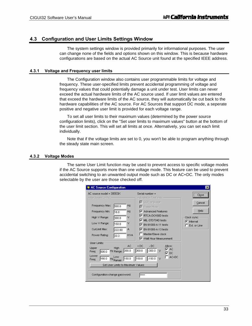
CIGUI32 Software User’s Manual
33
4.3 Configuration and User Limits Settings Window
The system settings window is provided primarily for informational purposes. The usercan change none of the fields and options shown on this window. This is because hardwareconfigurations are based on the actual AC Source unit found at the specified IEEE address.
4.3.1 Voltage and Frequency user limits
The Configuration window also contains user programmable limits for voltage andfrequency. These user-specified limits prevent accidental programming of voltage andfrequency values that could potentially damage a unit under test. User limits can neverexceed the actual hardware limits of the AC source used. If user limit values are enteredthat exceed the hardware limits of the AC source, they will automatically be cut back to thehardware capabilities of the AC source. For AC Sources that support DC mode, a seperatepositive and negative user limit is provided for each voltage range.
To set all user limits to their maximum values (determined by the power sourceconfiguration limits), click on the "Set user limits to maximum values" button at the bottom ofthe user limit section. This will set all limits at once. Alternatively, you can set each limitindividually.
Note that if the voltage limits are set to 0, you won't be able to program anything throughthe steady state main screen.
4.3.2 Voltage Modes
The same User Limit function may be used to prevent access to specific voltage modesif the AC Source supports more than one voltage mode. This feature can be used to preventaccidental switching to an unwanted output mode such as DC or AC+DC. The only modesselectable by the user are those checked off.

CIGUI32 Software User’s Manual
34
4.3.3 Voltage Range Pair
The iX Series supports dual voltage range pairs to allow either maximum current ormaximum voltage. The range pair in use can be changed from the configuration menu. Nopassword is needed to change this selection. This selection is made in the Power-onInitialization window however. Refer to section 4.5 on Power-on Settings.

CIGUI32 Software User’s Manual
35
4.4 Interface Window
The CIGUI32 supports both IEEE-488 (parallel) and RS232C (serial) communications.The Interface window is used for three different purposes.
1. As a means of changing the IEEE address used to connect to the AC Source. Onlyone AC Source power source is supported at a time in this version of the CIGUI32.This does include however multi-box AC Source units operated from a singlecontroller as is the case with 9003iX, 10001i/iX, 15001i/iX or 30003iX powersources. The IEEE address selected must match that of the connected AC Sourceunit or the communication between the PC and the unit will not be established.Refer to the AC Source instruction manuals for details on setting the IEEE addressfrom the front panel.
Figure 4-2 : Interface Settings
Note: If the source used is a Clock and Lock (-CLK), three consecutive IEEE addresses will beused to access phase A, B and C respectively. Note that only the address for phase Aneeds to be set and cannot exceed 28 to leave room for phase B and C (at 29 and 30respectively) If RS232C is used, Clock and Lock configurations are not supported as mostPC's do not have three Com ports available. In this case, only phase A of the system will beoperated.
2. To switch between connected mode (normal operation) and simulation mode. If apower source is found at the specified port, the program selects normal mode ofoperation. If the power source is set to a different IEEE address, or is otherwise notfound at the specified port, the simulation mode is automatically selected.
3. To interact with the connected AC Source unit directly over the IEEE or RS232C bus.The command line and response window can be used to issue SCPI commands to theAC Source unit. Any responses will be displayed in the response window located belowthe command line. A subset of commonly used commands can be found in the dropdown list box below the command line.

CIGUI32 Software User’s Manual
36
4.5 Power-on Settings
Power-on settings covers those source output parameters that can be initialized tospecific values at power up. These values take effect as soon as the AC source is poweredup and remain in effect until changed from the front panel or over the IEEE interface. Theinitialization values are retained in non-volatile memory. The source initialization window canbe used to inspect the active initialization values and if needed make modifications.
Figure 4-3 : Power On Settings
Modifications made are downloaded to the AC source and saved in non-volatile memoryas soon as the button is clicked. To close this window without affecting any changes,use the button instead.
Note Any changes made to the initial values do not affect the output of the power source untilafter it has been powered down and back up.
Changes made to any of steady state controls immediately affect the setting of theconnected AC source. This allows the user to slew values up or down using the mouse. Thismode of operation more closely reflects the operation of an actual front panel.
For iX Series units, the power on settings can be used to select a different waveformgroup at power-on. Four groups of 56 user defined waveforms each are available.Waveform groups can be switched only by changing the selected waveform group in thiswindow, closing the window to update the AC source and then performing a device clear ora power off/on cycle.
The Range Pair can be toggle between either 135/270 V or 150/300 V. The 135/270 Vcombination provides maximum current in each range. The 150/300 V pair provides highervoltage output at a reduced maximum current. (10 % reduction in maximum RMS current.)The selected range pair takes effect when the unit is turned on.

CIGUI32 Software User’s Manual
37
4.6 Interharmonics Generator Control
If the iX Series AC&DC Power source connected is equipped with the option -413interharmonics generator, this control window may be used to control this secondarygenerator. This generator is also used by the IEC 61000-4-13 Interharmonic Test. Seesection 8.5.
The interhamonics generator control screen supports the following user controls:
• Turn interharmonics generator on or off
• Set the interharmonic frequency.
• Set the amplitude coupling to the programmed steady state AC voltage or the fixedreference voltage.
• Set the fixed reference voltage if coupling to the reference voltage is selected
• Set the interharmonic amplitude in percent of either the programmed steady stateAC voltage or the fixed reference voltage.
The amplitude of the interharmonics output is programmed relative to either theprogrammed AC source voltage or the fixed reference voltage. If the amplitude is coupledto the reference voltage, the reference voltage can be set. If coupled to the steady stateAC voltage, the AC voltage can be set using the main CIGUI32 control window.
The Interharmonics control window may be left open if needed.
Note: Toggling the generator to off causes all interharmonic settings to be lost. Settings are resetto their defaults (0 %, 400 Hz) any time the interharmonics generator is turned off.

CIGUI32 Software User’s Manual
38
(This page intentionally left blank)

CIGUI32 Software User’s Manual
39
5 Transients
This chapter covers transient programming. Transients are an effective way ofgenerating common disturbances found on power lines. The AC sources are equipped withtransient list memory. The transient programming window is used to specify transient typesand parameters for each entry in this list. Once defined, the transient list can be executed aspecified number of times or continuously.
For long duration transients, you can check the Show popup checkbox locatedimmediately above the Start button. This will pop up a dialog box at the end of the transientexecution informing the oprator the transient has been completed.

CIGUI32 Software User’s Manual
40
5.1 Transient Data Entry
The transient window provides a grid-like data entry screen that is used to specifytransient type and parameters for each of the entries in the transient program list. Themaximum list size is set to 100 entries although the AC source may not be able to hold thatmany. In that case, the PC will prompt the user to set a start phase angle (AC mode) orbreak entry (DC mode) to divide the list into smaller sub lists. These sub lists are thendownloaded and executed in the sequence in which they appear.
Data entry can be done in either absolute or relative mode as indicated by the DataMode controls to the right of the data entry grid.
5.1.1 Absolute data entry
Absolute data entry of transients implies that actual Voltage and Frequency values areentered in the Voltage and Frequency columns. This is in contrast to Relative data entrywhere these values are interpreted as a percentage of a nominal value.
When using Absolute data entry, the upper and lower limits for the Voltage andFrequency columns are determined by the AC Source hardware limits. This does not includethe present voltage range however. If a voltage is set in a transient program that exceedsthe low voltage range and the source is set to the low voltage range, an execution error willoccur when the transient list is started. You can always toggle to the front panel controlwindow and change voltage range. You may also have to close the output relay beforestarting a transient list.
Note: It is usually not possible to toggle between absolute and relative transient data entry modewithout changing the numeric values entered in the grid.
5.1.2 Relative data entry
Relative data entry of transients implies that Voltage and Frequency values are enteredin a percentage of nominal. The nominal Voltage and Frequency to use are entered inseparate data entry field to the right of the data entry grid.
• When using Relative data entry, the upper and lower limits for the Voltage andFrequency columns are set to 0 and 200 %.
• When setting the voltage, make sure that 200 % of V nominal does not exceed themaximum voltage capability of the AC source.
• When setting the frequency, make sure that 200 % of F nominal does not exceedthe maximum frequency capability of the AC source.
Do not set the frequency to 0 % of F nominal. This would equate to zero Hz which is notpossible on any AC Source in AC mode.
Note : It is usually not possible to toggle between absolute and relative mode without changing thenumeric values entered in the grid.

CIGUI32 Software User’s Manual
41
5.1.3 Transient Data Entry Fields
This data entry grid consists of six to seven columns for the following fields:
Step No. Number of the transient step in the transient list. Steps are numberedfrom 1 to 100.
Trans.Type Transient type field. This is a pull-down field that lists all availabletransient types. More details on the various transient types will follow.
Duration (s) The duration field reflects the amount of time the AC source will waitbefore proceeding to the next step in the list. In case of a sweeptransient, the duration is used to determine the required slew rate forvoltage and or frequency.
Voltage Voltage value. For transients that affect voltage, this value will takeeffect as soon as the register is recalled. For voltage sweeps, the GotoV value reflects the start value. For voltage drops, this field is disabledas a voltage drop always drops the voltage to zero volt at the start ofthe register execution. For voltage steps, this value is the value set atthe output when the transient register is executed. For VoltageSag/Surge transients, the Goto V is the value the voltage will be at forthe time period specified in the Delay field. Whether it represents a sagor a surge will depend on the steady state voltage present at the timethe transient is executed.If relative data entry mode is selected, the column header changes toVolt (%).
Frequency (AC and AC+DC mode only) Initial frequency value. For transients thataffect frequency, this value will take effect as soon as the register isrecalled. For frequency sweeps, the Goto F value reflects the startvalue. For frequency steps, this value is the value set at the outputwhen the transient register is executed. For Frequency Sag/Surgetransients, the Goto F is the value the frequency will be at for the timeperiod specified in the Delay field. Whether it represents a sag or asurge will depend on the steady state frequency present at the time thetransient is executed.If relative data entry mode is selected, the column header changes toFreq (%).
Repeat (i and iX Series only) This field allows each individual transient step tobe repeated n number of times. The minimum value is 0 which meansthe steps is executed one time and not repeated. The maximum value is99, which means the step is executed 100 times. (once plus 99repeated executions). Note that this function has limited use as sometransient events require more than one list entry to function and thisrepeat function only works on an individual list entry at a time.When used on a sweep, the sweep will repeat so it can be use toeliminate multiple steps. When used on a step or delay, it merelymultiplies the dwell time by the number or reptitions. For drops, surgesand sags, it cannot be used as these transient types require two listentries to be programmed and each would end up having its repeat fieldset. For these steps, the repeat field is grayed out.
Waveform (iL and iX Series only) This field selects a waveform from the availablestandard or user defined waveforms to use during this step. Thedropdown list will display all available waveforms. Trying to run a

CIGUI32 Software User’s Manual
42
transient program that uses waveforms that have been deleted by theuser after setting up the transient list will result in an execution error.
Start Phs (AC and AC+DC mode only) Start angle of transient execution. Thisvalue reflects the phase angle at which the transient will start. Phaseangle fields are optional. If no phase angle is specified, the transient willstart at a random phase angle. Use the DEL key to clear this field if thephase angle needs to be cleared.
Break (DC mode only). In DC mode, the Start phase field is replaced with abreak field. Putting any number in this field will cause the list to bebroken into smaller sub-lists. This will allow programs up to 99 steps. Itwill cause a slight delay for each sub-list that needs to be downloaded.If all fields are left blank, the maximum number of steps on the i Seriesis 31.

CIGUI32 Software User’s Manual
43
5.2 Error Checking
As data is entered into each field, error checking is performed when the focus is movedfrom one field to the next. If appropriate, an error message will occur indicating the nature ofthe mistake. At the same time, the erroneous value is replaced with a default value. To fixthe error, accept the default or move the cursor back to the previous field (press Shift-Tab)and enter the correct value.
Error checking is based on hardware configuration limits determined by the connectedAC Source unit. There is one condition which is not checked however. This is related to thehigh or low voltage range setting presently active. Since the transient list can beprogrammed and saved for later use, it is possible that the voltage values used in atransient event are within limits if the AC Source is in high voltage range. In low voltagerange however, the same transient parameters are invalid as they exceed to maximumvoltage in the low range. No check is made on the present range setting. Voltage values areonly limited by the high voltage range value reported by the AC Source unit connected.
Consequently, if a transient event is downloaded that contains a voltage value thatexceeds the low voltage range limit and the unit is in the low voltage range at the time, anerror message will appear and the transient will not execute.
Note: While the CIGUI32 offers up to 100 transient list events, the AC source used may onlysupport a smaller number. The CIGUI32 works around such a hardware limitation by dividingthe list the user entered into smaller sub-lists when a number is entered in the Break field.This will cause a slight delay however as the next sub-list is compiled, downloaded andstarted. For sources that have less than 100 list entries (i/iX Series and HGA), a warningwill pop up if the number of steps used exceeds the available number. The warning willadvise the user to enter a break in the list at the required position in the list.
5.3 DC Transients
For i and iX Series applications, DC transients can be used. The AC source must beswitched to DC mode from the control panel before opening the transient window.
Note: On some older i Series models, DC voltage transients are not allowed to change polarity ina single event. Thus, it is important to insert a Step to 0 Volt in between positive andnegative voltage events.

CIGUI32 Software User’s Manual
44
5.4 Triggering Waveform Acquisitions
When using an iX or iL Series AC source, itis possible to trigger the acquisition of voltageand current waveforms on all phases. This isaccomplished through the Measurement,Waveform window. The trigger moment can beset to coincide with any transient step list.
This setting will only be effective if thewaveform acquisition mode is set to“Synchronize with Transient”. In this mode,voltage and current waveform data is acquiredon all phases simultaneously. While the“Synchronize with Transient” mode remainsselected, the Meas button in the waveformacquisition window only uploads the waveform data selected. (by type - voltage or currentand by phase A, B or C.).
If the “Synchronize with Transient” mode is off, waveform data is acquired in a Free Runmode each time the Meas button is clicked. In this mode, there is no synchronization.
This synchronized acquisition mode is particularly useful for capturing single shot eventssuch as start up currents that rely on a specific programmed voltage event which is createdusing a transient program. Such transient programs can be as simple as a single step thatturns the output voltage on at a specific phase angle, e.g. 90 degrees.

CIGUI32 Software User’s Manual
45
5.5 Transient Types
The CIGUI32 program supports several different transient types. Each transient typeand its parameters are described in more detail in this section. The available transient typesare :
Table 5-1 : Available Transient List Events
no. Type Abbreviation Mode
1. Empty Empty AC, AC+DC, DC
2. Voltage dropout V Drop AC, AC+DC, DC
3. Voltage step V Step AC, AC+DC, DC
4. Voltage surge/sag V Srg/Sag AC, AC+DC, DC
5. Voltage sweep V Sweep AC, AC+DC, DC
6. Frequency step F Step AC, AC+DC
7. Frequency surge/sag F Srg/Sag AC, AC+DC
8. Frequency sweep F Sweep AC, AC+DC
9. Voltage and Frequency step VF Step AC, AC+DC
11 Voltage and Frequency sweep VF Sweep AC, AC+DC
10. Delay Delay AC, AC+DC, DC
Note: When executing the transient list, the CIGUI32 will stop processing the list as soon as itencounters and EMPTY entry. Thus, no matter what list events follow, the transient list willbe interpreted up to this point only. You can use this to temporarily cut back the length of alist without erasing all entries.
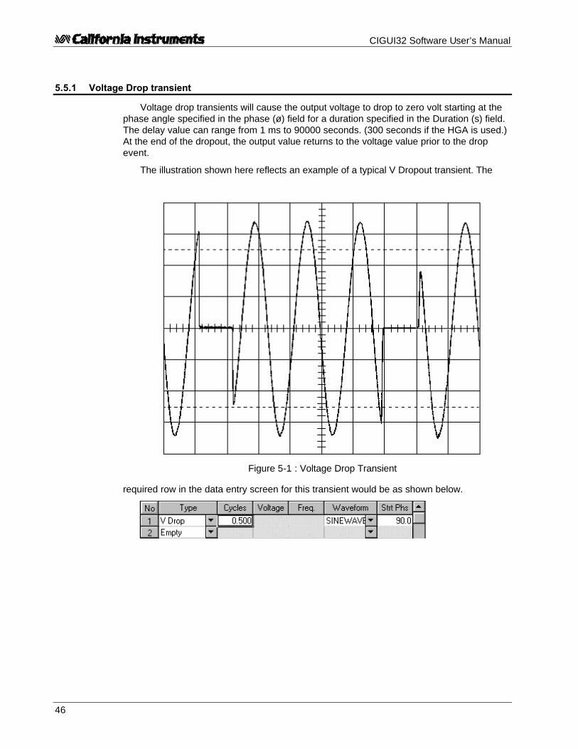
CIGUI32 Software User’s Manual
46
5.5.1 Voltage Drop transient
Voltage drop transients will cause the output voltage to drop to zero volt starting at thephase angle specified in the phase (ø) field for a duration specified in the Duration (s) field.The delay value can range from 1 ms to 90000 seconds. (300 seconds if the HGA is used.)At the end of the dropout, the output value returns to the voltage value prior to the dropevent.
The illustration shown here reflects an example of a typical V Dropout transient. The
required row in the data entry screen for this transient would be as shown below.
Figure 5-1 : Voltage Drop Transient

CIGUI32 Software User’s Manual
47
5.5.2 Voltage Step transient
Voltage step transients will cause the output voltage to go to the value specified in theVoltage field starting at the phase angle specified in the phase (ø) field for a durationspecified in the Duration (s) field. The delay value can range from 1 ms to 90000 seconds.(300 seconds if the HGA is used.). At the end of the delay period, the output value will be atthe Voltage step value.
The delay value is specifically useful if the step transient is part of a list of linkedregisters. In this case, the delay value will determine how long the value remains at thespecified value before the next event in the list executes. At that time, whatever value is setin the next step may change the voltage to a new value.
The illustration shown here reflects an example of a typical V Step transient. Therequired rows in the data entry screen for this transient would be as shown below.
Figure 5-2 : Voltage Step Transient

CIGUI32 Software User’s Manual
48
5.5.3 Voltage Surge or Sag transient
Voltage surge and sag transients will cause the output voltage to go to the valuespecified in the Voltage field starting at the phase angle specified in the phase (ø) field for aduration specified in the Duration (s) field. The delay value can range from 1 ms to 90000seconds. (300 seconds if the HGA is used.). At the end of the delay period, the output valuewill still be set back to the value prior to the surge or sag.
If the Voltage value is set to the same value as the value that is present when thisevent is executed, the V Srg/Sag transient effectively becomes a V Step transient.
The illustration shown here reflects an example of a typical V Srg/Sag transient. Therequired row in the data entry screen for this transient would be as shown below.
Figure 5-3 : Voltage Surge/Sag Transient

CIGUI32 Software User’s Manual
49
5.5.4 Voltage Sweep transient
Voltage sweep transients will cause the output voltage to change gradually from thepresent value to the Voltage value specified by the sweep event over a period of timespecified by the Duration field. The delay value can range from 1 ms to 90000 seconds.(300 seconds if the HGA is used.). At the end of the delay period, the output value willremain at the value specified by the Voltage field. The slew rate is calculated from the deltavoltage and duration values.
The illustration shown here reflects an example of a typical V Sweep transient. Therequired row in the data entry screen for this transient would be as shown below.
Figure 5-4 : Voltage Sweep Transient

CIGUI32 Software User’s Manual
50
5.5.5 Frequency Step transient
Frequency step transients will cause the output frequency to go to the value specified inthe Frequency field starting at the phase angle specified in the phase (ø) field for a durationspecified in the Duration (s) field. The delay value can range from 1 ms to 90000 seconds.(300 seconds if the HGA is used.). At the end of the delay period, the output frequency willremain at the Frequency value specified.
The illustration shown here reflects an example of a typical F Step transient. Therequired row in the data entry screen for this transient would be as shown below.
Figure 5-5 : Frequency Step Transient

CIGUI32 Software User’s Manual
51
5.5.6 Frequency Surge or Sag transient
Frequency surge and sag transients will cause the output frequency to go to the valuespecified in the Frequency field starting at the phase angle specified in the phase (ø) fieldfor a duration specified in the Duration (s) field. The delay value can range from 1 ms to90000 seconds. (300 seconds if the HGA is used.). At the end of the delay period, theoutput frequency will return to the value before the surge or sag event occurred.
The illustration shown here reflects an example of a typical F Sag transient. Therequired row in the data entry screen for this transient would be as shown below. Thesteady state frequency is assumed to be 50 Hz.
Figure 5-6 : Frequency Surge/Sag Transient

CIGUI32 Software User’s Manual
52
5.5.7 Frequency Sweep transient
Frequency sweep transients will cause the output frequency to change gradually fromthe present frequency value to the specified Frequency value over a period of timespecified by the Duration field. The delay value can range from 1 ms to 90000 seconds.(300 seconds if the HGA is used.). At the end of the delay period, the output frequency willremain at the value specified by the Frequency field.
Note: If the Frequency value is set to the same value as the present Frequency, the F Sweeptransient effectively becomes a F Step transient.
The illustration shown here reflects an example of a typical F Sweep transient. Therequired row in the data entry screen for this transient would be as shown below.
Figure 5-7 : Frequency Sweep Transient

CIGUI32 Software User’s Manual
53
5.5.8 Voltage and Frequency Step transient.
The VF Step transient is a compound transient that combines a Voltage and aFrequency step into a single event. When executed, both voltage and frequency changesimultaneously. Refer to section 5.5.2 and section 5.5.5 for details on separate voltage andfrequency steps.
The illustration shown here reflects an example of a typical VF Step transient. Therequired row in the data entry screen for this transient would be as shown below.
Figure 5-8 : Voltage and Frequency Step Transient

CIGUI32 Software User’s Manual
54
5.5.9 Voltage and Frequency Sweep transient.
The VF Sweep transient is a compound transient that combines a Voltage and aFrequency sweep into a single event. When executed, both voltage and frequency changesimultaneously. Refer to section Error! Reference source not found. and section Error!Reference source not found. for details on separate voltage and frequency sweeps.
The illustration shown here reflects an example of a typical VF Sweep transient. Therequired row in the data entry screen for this transient would be as shown below.
Figure 5-9 : Voltage and Frequency Sweep Transient

CIGUI32 Software User’s Manual
55
5.6 Transient Phase Selection
The same transient program can be used for one phase, twophase or all three phases of a three phase system. The Phaseselection check boxes located in the bottom right corner of theTransient window are used for this purpose. If the connected ACSource unit is a single phase instrument or a three phase unit withthe mode option set to single phase, these controls will be disabledand only phase A will have a check mark. For three phase units orunits with the phase mode option set to three phase, these controlscan be set by the user.
When the transient list is executed, the status of these phase check marks isincorporated in the generation of the list data sent to the AC Source unit.
Note: Phase information is not stored and retrieved as part of the general transient information.(See section Error! Reference source not found.) This allows the same program to beused on a single phase, two phases or all three.

CIGUI32 Software User’s Manual
56
5.7 Executing Transient Lists
The transient list data entered by the user is downloaded to the source as soon as theStart button is pressed. The transient program may have to be broken into one or more sub-lists. Sub-lists are needed if:
• A start phase angle is specified at any step other than step 1
• The number of list points exceeds the capabilities of the AC source in use
If more than one sub-list is required, each sub-list is downloaded after the previous onecompletes execution. This download may require some time so there will be a longer delaybetween sub-lists than there is between individual events in the same sub-list. To avoid thebreak-up of your program in sub-lists, do not use the start phase angle other than in the firstevent. This will limit the size of your program to the number of events supported by thesource. The following limits apply in this case:
Table 5-2 : Transient List Size by Model
Model Phase angle at firstevent only
More than one phaseangle (sub-lists)
iL Series 99 99
iX Series 31 99
i Series 31 99
HGA 15 99
The actual number of events send to the source may be one event larger than thenumber entered by the user. This is because the CIGUI32 automatically appends anadditional step to bring the output back to the original start values after some transient typessuch as Vdrop and Vsrg/sag if these types occur at the end of the transient list.
Transient execution always takes place on the AC source through the embeddedprocessor and as such runs in real time. Nevertheless, there are some performanceconsiderations. (See next paragraph of details.)

CIGUI32 Software User’s Manual
57
5.7.1 Using start phase angles
A transient list can be started at a specified phase angle of the output waveform butonly at the beginning of the list. Once started, the dwell times (duration field values) areused to pace the output changes. To allow different start phase angles to be used as part ofthe same transient program, the CIGUI32 will break the transient list data it sends to the ACsource into sub-lists any time a start phase angle field is used. Since the AC source canhold and execute only one transient list at a time, the CIGUI32 must wait for the presentlyexecuting sub-list to finish before it can send and trigger the next part of the user’s listprogram. This process of downloading and triggering a sub-list takes time. The exact timerequired depends on:
• the speed of the interface used (RS232C is somewhat slower than IEEE-488)
• the size of each sub-list. A sub-list can be as small as one event or as large as 99events.
• the type of processor and clock frequency of the PC used. (A 800 MHz Pentium III willbe able to process an queue up the next sub-list faster than a 200 MHz 486)
If you are trying to control the total run-time of a transient list program, do not use startphase angles other than in the first event of your list. On some AC sources, this may limitthe length of your transient list program. (i/iX Series : 31 events, HGA : 15 events)
5.7.2 Continuous Mode
If the Continuous mode of execution is selected, the program will run indefinitely.However, between each loop through the list, the entire list (or sub-lists if start phase anglesin AC mode or breaks in DC mode are used) is downloaded to the AC source for each loop.This process takes time so there will be a delay between each loop through the program.
5.7.3 Count Mode
When the count mode is used to run the program N number of times, the entire list (orsub-lists) is downloaded to the AC source every time. This allows the CIGUI32 to inform youof the number of runs accomplished so far.

CIGUI32 Software User’s Manual
58
5.8 Managing Multiple Transient Programs
Multiple transient program lists can be saved to disk for later use. This allows the userto create his or her own library of commonly used transient programs.
5.8.1 Saving transient lists
When the button is clicked, a file dialog box will appear prompting the user tosupply a transient program file name. Any eight-character name can be used. If an existingtransient program file is selected, its contents will be overwritten with the active data fromthe transient entry screen. If a new name is entered, the transient data will be saved underthe new file name. A comment field can be added at the top of the transient list screen. Thiscomment is saved with the transient data in the same file.
5.8.2 Retrieving transient list
When the button is clicked, a file dialog box appears listing all available transientlists on disk. Use the mouse to select the desired file and press on OK to load it. The newinformation will replace the present contents of the data entry fields.
5.8.3 Editing transient lists
Transient lists can be edited by overwriting any cell of any row. It is also possible toInsert or Delete a specific row. To insert a new empty row in an existing transient program,position the edit box on the row at which the new row is to be inserted and click on theInsert button.
To delete a row, position the edit box on the row to be deleted and click on the Deletebutton.
5.8.4 Erasing transient lists
To erase the entire contents of the data entry area, the user has two options. Eithercreate a transient list file consisting of only Empty transient types and save it on disk with adescriptive name such as “EMPTY.TLS”. Anytime the data present needs to be erased, loadthe EMPTY.LST file. Alternatively, the button, located in the bottom right corner can beused. When this button is clicked, the user will be asked for a confirmation before all entriesare erased.
Press No to abort the erase operation. If Yes is selected, all entries will be erased. Youmay want to store the list information to disk before executing a Clear All.

CIGUI32 Software User’s Manual
59
5.8.5 Transient list file extension
Transient list files always use the “.TLS” extension. This extension is reserved for thispurpose and no other files using the same extension should be stored in the same sub-directory as used to hold transient list programs.
Transient list files are stored in simple ASCII formats to facilitate documentation andtransfer of transient list programs through email systems. Nevertheless, the user isdiscouraged from editing these files with a text editor. The file format for this file type isprovided in section Error! Reference source not found. of this manual.
Transient lists created with the 16 bit version of the Cigui can be used in the Cigui32with the following restictions:
The .tls files need to be opened using a text editor such as Windows Notepad and aone line comment has to be added at the beginning of each file. After adding this line – anytext may be used – the file can be saved and opened in the Cigui32.
5.8.6 Automatic save on CLOSE
Because entering transient lists can be time consuming, it is important not toaccidentally loose information when the Transient window is closed. To prevent this fromhappening, the CIGUI32 program will automatically save the contents of all the parameterfields any time the button is clicked. The data is stored to a default file called“CIGUI32.DTL” in the program directory. Any time the Transient window is opened, theCIGUI32 looks for the presence of this file. If it can be found, its contents are loaded in thetransient data entry fields. Consequently, if the user exits the transient window using the
button and then re-enters it, all data will be restored, even if no Save List operationwas performed.
The same is not true when the transient window is closed with the button, theESC key or the Close sub-menu in the control box menu. (also activated with the ALT-F4key combination.

CIGUI32 Software User’s Manual
60
5.8.7 Run time errors and other transient execution issues
If you experience run time errors when executing a transient program, check the following:
1. Does any of the voltage values generated select the maximum voltage for the low range? Ifso, make sure the high voltage range is selected before starting the transient program.
2. Is any of the time duration values used set to less than the minimum time allowed? This isespecially likely to happen while in Time in Cycles modes at higher frequencies.
3. Is the output relay closed? The output relay must be closed before starting a transient.
4. Does the slew rate required to effect any of the V, F or VF Sweeps in your transientprogram require a slew rate less than 0.1 V/sec or 0.1 Hz/sec? If so, the slew rate is out ofrange and a -222 Data out of Range error will result once the powers source compiles thetransient list program sent by the GUI. In this case, the transient will not execute. (Note thatthe slew rate for firmware 2.22 of the iX Series has been extended down to 0.001 V/secand 0.001 Hz/sec to allow slower sweeps to be programmed.
5. Be aware of rounding errors that may occur when running sweeps that run for a long periodof time. (> 1000 sec). Since the slew rate is a fraction of delta V or F and the dwell time,some rounding may occur is the required theoretical slew rate needed extends beyond onedigit behind the decimal point (3 digits for iX Series with firmware 2.22 or higher). Thisrounding error could result in the final V or F reached being slightly off from the expectedvalue. To adjust for this, calculate the actual dwell time that would result in a slew rate thatdoes not require rounding on the par to the power source controller.
If no obvious explanation can be found, use the Bus Monitor feature to capture the bus traceand email this information to California Instruments ([email protected]) for analysis.

CIGUI32 Software User’s Manual
61
5.9 Transient Editor Control Window
The transient list editor provides and alternative and somewhat more direct method ofspecifying output transients. The transient list editor screen provides direct access to thei/iX Series based transient list system. Its function is largely similar to that of the regularTransient window and care should be taken not to open both windows at the same time, asthey will conflict with each other.
Figure 5-10: Transient List Editor Control Window.
The Transient List editor window uses a more direct approach to specifying transientlist sequences by programming each of up to 14 list parameters individually. Whether anentry is a step, sweep, surge or sag is determined by the slew rates specified. No highlevel functions are provided as is done in the regular Transient window. This provides ahigher level of control than otherwise possible.
For multi-phase AC power configurations, individual lists can be programmed for eachoutput phase. This is not possible with the standard Transient window. Also, any repeatsselected will be executed on the AC Source with no dead time in between, as is the case inthe regular Transient window.

CIGUI32 Software User’s Manual
62
5.9.1 Transient List Editor Functions
The transient list editor control window can be used to:
Function Description
Read Transientfrom AC Source
From the Transient menu, select Read Source List totransfer the content of the AC Source's transient list systemto the PC. The contents will be displayed in the data gridand can be edited if needed.
Write Transient toAC Source:
From the Transient menu, select Write Source List to sendthe data from the data grid to the AC Source. Once written,a transient can be executed from the front panel of the ACsource if needed.
Run Transient From the Transient menu, select Run to execute thetransient. The data from the data grid is transferred to theAC Source first and then the AC source is triggered. Therun parameters such as the number of times to repeat thetransient and the start phase angle must be set beforeexecuting the transient.
The frequency and one or more voltage phases can beselected for execution. Parameters not selected are set toFIXED mode meaning they will not participate in thetransient execution.
If the output relay is open, it will be closed automaticallybefore transient execution begins.
On iX Series AC sources, the waveform acquisition isautomatically cross-triggered from the first Acq Trigger entryset to 1 in the last column of the data grid. Use theMeasurement, Waveform acquisition window to display theacquired data.
Load and Save toDisk
From the File menu, you can save and recall transient datato disk. Transient data is stored in ASCII files with a .TRLextension. (TRansient List)
Edit Lists Use the data entry grid to edit transient list data. Make sureeach transient list has equal length or the AC Source willgenerate an error when trying to execute. Transient listswith a length of only 1 entry are automatically extended bythe AC source to match the overall list length.
Table 5-3: Transient List Editor Control Window Functions

CIGUI32 Software User’s Manual
63
5.9.2 Modes and Restrictions
The Transient List capabilities are available in single, split and three-phase modes forboth AC, DC and AC+DC modes of operation. The following restrictions are imposed by theAC&DC power source:
No. Restriction / Limitation
1. Only the i/iX Series AC&DC Power sources are supported in this mode.
2. Maximum list length is 32 entries. This is determined by the i/iX Seriescontroller capability.
3. The slew rates for Frequency and Voltage cannot exceed 100000000.0Hz/sec and 100000000.0 Volt/sec respectively.
4. The Waveform names entered in the Function fields must be availablein the AC sources waveform list.
5. The dwell time is limited to 90000.000 seconds per entry.
6. The Repeat field for each entry ranges from 0 (do not repeat orexecute each entry only once) to 99 (repeat 99 times for a total of100).
7. The Transient List execution repeat field ranges from 1 (run one times)to 99999.
8. The start phase angle must be between -360.0 to + 360 degrees.
9. Voltage and Frequency values are limited by the limits set on the ACsource.
Table 5-4: Transient List Editor Restrictions
5.9.3 Transient List Editor Execution Error Messages
No error checking is performed until a transient is executed. At this time, the followingerror messages may be generated before the transient execution is triggered:
• If no parameter is selected under List Selections, no transient is run.
• Any of the lists is of unequal lengths.
The following error messages may be generated after the transient execution istriggered:
• Slew exceeds Dwell. The combination of dwell time and slew rate exceeds the endvoltage or end frequency specified in the list. Thus, to go from 0 V to 100 V in 1sec, the slew rate cannot be less than 100 V/sec or the 100 V will not be reached in1 sec. It is ok for the slew rate to be higher. If so, the 100 V will be reached beforethe dwell time is over and the voltage will remain at 100 V until the end of the dwelltime. Slew rates set to 100000000.0 are equivalent to max slew which effectivelymakes it a frequency or voltage step.
• Data out of Range. If the slew rate required to effect any of the V, F or VF Sweepsin your transient program is less than 0.1 V/sec or 0.1 Hz/sec, it is out of range anda -222 Data out of Range error will result once the power source compiles thetransient list program sent by the GUI. In this case, the transient will not execute.

CIGUI32 Software User’s Manual
64
(Note that the slew rate for firmware 2.22 of the iX Series has been extended downto 0.001 V/sec and 0.001 Hz/sec to allow slower sweeps to be programmed.
• Be aware of rounding errors that may occur when running sweeps that run for a longperiod of time. (> 1000 sec). Since the slew rate is a fraction of delta V or F and thedwell time, some rounding may occur is the required theoretical slew rate neededextends beyond one digit behind the decimal point (3 digits for iX Series withfirmware 2.22 or higher). This rounding error could result in the final V or F reachedbeing slightly off from the expected value. To adjust for this, calculate the actualdwell time that would result in a slew rate that does not require rounding on the parto the power source controller.
Other run time errors may be generated by the AC source upon compilation of thetransient list information but prior to execution. If so, the error message is displayed and thetransient will not run.

CIGUI32 Software User’s Manual
65
6 Waveform Generation
Waveform generation is supported on iX Series, iL Series and HGA controlled ACpower sources. A digital synthesis arbitrary waveform generator is used to create customdefined waveforms. The CIGUI32 supports two distinct methods of creating customwaveforms:
Harmonic Waveforms: Harmonic waveforms are synthesized from user providedrelative amplitude and phase angles for up to 50 integerharmonic frequencies. Amplitudes are specified in percent from0 to 100. Phase angles are specified in degrees from –360.00° to + 360.00°.
Arbitrary waveforms: Arbitrary waveforms can be created in many different ways.This program offers some built in waveforms but also acceptsdata from comma separated files that can be generated bypopular application programs such as spreadsheets.
Note that arbitrary waveforms are subject to the capabilities and limitations of the ACsource used. This may imply the inability to generate a waveform with a DC offset on anAC source with an AC coupled output stage. (Transformer) It also implies that inter-harmonics cannot be generated as the AC source operates from a single time base andrepeats the waveform shape in its buffer at the programmed fundamental frequency. If thestart and end points of the arbitrary waveform specified by the user are no identical, theoutput will show a discontinuity as the waveform register ‘wraps’ around. For inter-harmonics generation such as required for IEC 61000-4-13, the –413 option must be addedto the iX Series.

CIGUI32 Software User’s Manual
66
6.1 Creating Harmonic Waveforms
Harmonic waveforms can be defined by specifying the relative amplitude of eachharmonic with respect to the fundamental frequency. The actual fundamental frequency ofthe signal is not relevant for creating the waveform data. At execution time however, thefundamental frequency will be the selected steady state frequency. Keep in mind that theoutput stage of the AC amplifier may have an upper bandwidth limit. Thus, if the fundamentalfrequency is set to 5000 Hz, the 50th harmonic would be 250 KHz which is beyond thebandwidth limit on most AC power sources. For practical applications at 50 and 60 Hz, theupper harmonic is no more than 3 KHz, which is within the capabilities of all CaliforniaInstruments AC power sources. To prevent damage to the AC Amplifier output stage, the
CIGUI32 limits the amplitude of the higher order harmonics. As you enter the amplitudepercentage, you may notice that the program reduces it to a maximim allowable value. Thesecond harmonic can be 50 % max., the third 33 % max, the fourth 25 % max. etc.
The default display mode is Auto preview, which updates any changes made to the datatable immediately to the waveform or bar chart display at the bottom. On slow PC’s, it maybe more convenient to update the graph only when all data points have been entered. Inthat case, turn off the Auto preview mode and pressing the preview button to previewharmonic waveforms or bar charts. This also causes the actual data points to begenerated. As such, you cannot download a harmonic waveform unless you perform apreview when the Auto preview mode is turned off.
Figure 6-1: Harmonic Waveform Generation Window

CIGUI32 Software User’s Manual
67
The Transfer button causes the waveform data to be sent to the AC source. Insimulation mode, you will see a message indicating there is no power source connected.Data is downloaded using a user provided name. If the harmonic data was loaded from adisk file, the filename will be used as the waveform name. Note that waveform namestransferred to the AC source are limited to twelve characters. Do not use specialcharacters such as space, comma, decimal point, question mark, ampersand etc. TheWaveform Register drop down list shows all the custom waveforms presently loaded in theAC source connected. If harmonic data was not loaded from disk, the waveform data pointswill be downloaded under the same name as the name selected in this box. Note that thiswill overwrite the data that was there before. To avoid overwriting existing waveform data inthe AC source memory, select an >EMPTY< entry from the list before pressing on theTransfer button.
Harmonic table data can be saved to disk for future use. This allows a library of oftenused harmonic waveforms to be created. Note that both the harmonic data from the table issaved to disk as well as the actual waveform data points, which are send to the AC powersource. This makes the harmonic data accessible to other programs. It also allows aharmonic waveform to be loaded in the Arbitrary waveform window for further editing. Thefile extension for harmonic data table files is .HWV which is short for Harmonic WaVeform.The file extension for arbitrary waveform data is .ARB which is short for ArBitraryWaveform Both files are comma separated value ASCII files. The same name is used forboth files.
Note that HWV data files cannot be loaded in the Arbitrary waveform window. Only theARB version can be loaded there.
The Clear button can be used to quickly erase the entire data entry table contents.Make sure you save the data as a file if you have a need for it later.

CIGUI32 Software User’s Manual
68
6.2 Creating Arbitrary Waveforms
The arbitrary waveform window allows you to define, import, view, manipulate anddownload arbitrary waveforms to the power source. There are four sources of waveformdata available:
• Built in function library• Waveform data point editor• Digital Oscilloscope download• CSV files created with other application programs
The purpose of this window is to manage the various sources and download thewaveform data to any of the available registers in the AC source under a user specifiedname.
The Waveform Register drop down list shows all the custom waveforms presentlyloaded in the AC source connected. If arbitrary waveform data was not loaded from disk,the waveform data points will be downloaded under the same name as the name selected inthis box. Note that this will overwrite the data that was there before. To avoid overwritingexisting waveform data in the AC source memory, select an >EMPTY< entry from the listbefore pressing on the Transfer button.
Note: When downloading waveform data to a HGA controlled AC source, a warning message mayappear indicating the presence of a DC component in the waveform to be downloaded. Beaware that the HGA does not pass DC levels in arbitrary waveforms as it is AC coupled.
Arbitrary data can be saved to disk for future use. This allows a library of often usedwaveforms to be created. Note that the actual waveform data points which are send to theAC power source are saved to disk. The file extension is “.ABW” which is short forArBitrary Waveform. These files are comma separated value ASCII files.

CIGUI32 Software User’s Manual
69
6.2.1 Editing Waveform Data
The Waveform Editor window allows you to edit theselected waveform data one data point at a time.Changes made become effective when the “Close”button is pressed. If any value entered manually is foundto be out of range (Range is -Vpeak to +Vpeak), an errormessage is shown identifying the first position in the edittable where an out of range value was found. All valuesmust be within these limits before the new data isaccepted. If you decide not to make any changes, pressthe Cancel button to exit.
The waveform editor allows you to edit, insert ordelete individual data points. Position the cursor on thedata point you want to delete and press the Delete buttonto remove a data point. Deleting a data point will cause anew data point with value zero to be added at the end ofthe waveform data record since the record size is alwaysfixed.
To insert a new data point, position the cursor at the desired insertion point and pressthe Insert button. Inserting a data point will cause the last data point to be dropped from thewaveform data.
To clear the entire data record to all zero, use the Clear button.

CIGUI32 Software User’s Manual
70
6.2.2 Waveform Library
A library of six commonly usedAC waveforms is provided. Thewaveforms offered by this libraryare mathematically generatedbased on the parameters youprovide. Specifically, the followingwaveforms are available:
Sine Standard Sine wave. Useful as a base signal tomodify using the Edit Waveform Data menu. Theamplitude can be set from 50 to 100 percent of fullscale. Use less than 100 percent only if you want tosuperimpose glitches that exceed Vpp.
Triangle Signal rises from - Vpp to + Vpp in the first 180° andthen decreases back to -Vpp.
Twelve Step Sine Signal commonly found in motor control applications
NOISY SINE Sine wave with added pseudo-random noise. Thepercentage of noise added can be set between 1and 50 percent of Vpp
Clipped Sine Sine wave clipped between 1 and 50 percent of Vpp.
Goto This selection will cause a glitch to be superimposedon the selected waveform at a user specified level ofVpp and at user specified phase angle. The glitchduration can be set between 1 and 12°.Be careful no to generate too much DC offset whenusing AC coupled output power amplifiers. (iLSeries and HGA) Try to balance the output signal byputting an opposite polarity event at a 180° phaseoffset. When using the i Series, this is not requiredas it has a DC coupled output.
Note : Waveforms created by the Library function are not automatically saved Select Save As... ifyou want to save the displayed waveform to disk. These waveforms can be used as is oras a starting point for more complex waveforms through the use of the waveform editor.

CIGUI32 Software User’s Manual
71
6.2.3 Using Spreadsheets to generate waveform data
In addition to the built in library of waveforms, you can use other programs to generatewaveform data for downloading to the AC source. Spreadsheets such as Excel and Lotus123 are commonly available tools for this purpose.
If you are using an HGA controller, organize your spreadsheet to contain two columns(A and B) and 4096 rows. (One for each data point). Put the horizontal (X) time coordinatein column A and the vertical amplitude value (Y) in column B. If you are using the HGAcontroller, the Y value should be scaled between +2047 and -2048 to take full advantage ofthe vertical resolution of the HGA. Make sure you have no DC component if the HGA isused with an AC amplifier that has output transformers. The program will issue a warning isyou try to download waveforms that have more than 2 % DC level to protect the ACamplifier output transformers from saturating.
If you are using an iX or iL Series source, organize your spreadsheet to contain twocolumns (A and B) and 1024 rows. (One for each data point). Put the horizontal (X) timecoordinate in column A and the vertical amplitude value (Y) in column B. The Y value shouldbe scaled between +2047 and -2048. If you are using an iL Series power source, any DClevel will automatically be removed. the iX Series is DC coupled and will accept a DC offsetin arbitrary waveforms.
You can use the Graphing capabilities of the spreadsheet program to preview yourwaveforms. Once you are satisfied with the data, save it to disk in a Comma SeparatedValue format (CSV extension). This format is widely used and can be read by this program.
NOTE: Users in countries outside the US that use local decimal and list separator characters mayhave to set their Windows International settings to use the decimal point as a decimalseparator and use a comma as the list separator.
A sample output file segment is shown below. This file can be opened in the Arbitrarywaveform window by selecting CSV as the file type instead of the default ABW extension.
INTRHARM,0,01,4.1064482,8.2127833,12.318894,16.424675,20.529996,24.634757,28.738848,32.842159,36.9445510,41.04595

CIGUI32 Software User’s Manual
72
6.2.4 Transferring data from a digital storage scope
This function will transfer data from the connected oscilloscope to the PC for storageand downloading to the HGA. There are some important considerations when using thisfunction. Specifically, make sure the following conditions are met:
1. The oscilloscope must display exactly one single period of the signal to be captured onchannel 1.
2. The amplitude of the displayed signal must be as large as possible without starting toclip.
3. The Channel 1 input must be AC coupled (No DC component)
To meet these conditions, the oscilloscope must have vernier controls on both the timebase and the amplitude controls. Un-calibrated vernier controls are fine since this programis only concerned with the waveform shape, not its amplitude and frequency. Amplitude andfrequency will be controlled by the AC source.
Note Waveform transfers from the Oscilloscope can be time consuming since the data needs tobe scaled to exactly fit the AC source record length. A progress monitor is displayedshowing the state of the conversion process.
Presently, only the HP54600 family of DSO’s is supported by the CIGUI32. This is arelatively inexpensive storage scope that is widely available. The scope needs to beconnected to the IEEE-488 bus and the correct IEEE address needs to be setup in theCIGUI32 for this function to work properly. The DSO type and address can be selected inthe Options, Scope setup menu.

CIGUI32 Software User’s Manual
73
7 Measurements
This chapter discusses the various measurements that are available from the ACSource. Depending on the source model, advanced harmonic analysis measurements maybe available.
Both types of measurements can be displayed on screen and stored to disk. Examplesare provided for using measurement data obtained from the AC source in spreadsheetprograms such as Excel.
Figure 7-1 : Measurement Window

CIGUI32 Software User’s Manual
74
7.1 Standard Measurements
The AC Source can provide up to twenty-five parameters in case of a three phasesystem or seven in case of a single phase system. Each parameter takes a certain amountof time to obtain. If all nineteen parameters are requested, the total measurement time canapproach 5 seconds. Since not all parameters are relevant for all applications, the user candeselect those measurements that are not critical and thus reduce the measurement cycletime. Also, if any parameter can be derived from other measured values, it is calculated onthe PC in software to avoid unnecessary data transfers. This can speed up themeasurement cycle considerably.
Measurements will only be taken for those parameters and on those phases for which acheck mark is present. In case of a single-phase system or a three phase system withMODE option in single phase mode, phase B and phase C will be disabled.
If all check marks are removed, only the frequency will be measured. Frequencymeasurements are always enabled and cannot be turned off.
Note: If DC mode is used on an i or iX Series source, there is no frequency measurement.
Measurements that are disabled will retain their most recent value but will be dimmed toindicate that they are no longer updated.
Line to Line Voltage readouts
Three phase measurements are available only if the AC source used has three phasemode. These measurement values are calculated from the line to neutral values and theprogrammed phase angles. If three phase Line to Line values are not needed, the bottompart of the measurement window can be removed by checking off the V(L-L) check box.
It is possible to enable and disable measurements while a measurement cycle is inprogress, but the effect of the change may not be visible until the next cycle if the changewas made after the measurement has been displayed for the present cycle already.Measurements are made in the following sequence. Disabled measurements and/or phasesare skipped.
Frequency Voltage phase ACurrent phase A Phase angle phase APower phase A Apparent power phase APower Factor phase A Peak Current phase ACrest Factor phase A Voltage phase BCurrent phase B Phase angle phase BPower phase B Apparent power phase BPower Factor phase B Peak Current phase BCrest Factor phase B Voltage phase CCurrent phase C Phase angle phase CPower phase C Apparent power phase CPower Factor phase C Peak Current phase CCrest Factor phase C Line to Line Voltages
Note: The Clr button can be used to reset the peak current reading to zero

CIGUI32 Software User’s Manual
75
7.1.1 Measurement modes
Two measurement modes are supported by the CIGUI32 program. Theyare both selected from the measurement window using the Mode fieldlocated on the right hand side of the window. The following modes areavailable :
Run Once mode This mode will cause all measurements to be takenonce when the button is clicked. Once a cyclehas been started, it will run through completely, evenif the button is clicked. This is to avoidincomplete measurement records when the data logging function isenabled.
Cycle mode In this mode of operation, measurements are taken continuously.This mode of operation is required for data logging applications. It isselected automatically when the data logging function is enabled.The cycle mode is started using the button and stopped usingthe button. The repeat rate is determined by the time intervalset at the bottom of the measurement screen, regardless ofwhether data logging is enabled or not.
7.1.2 Stay on top feature
The measurement window is a non-modal window (refer to section Error! Referencesource not found.) and can thus be left open at all times while the CIGUI32 program isrunning. To use the measurement window for monitoring load characteristics while workingin other windows programs, the stay on top feature can be useful as it allows you to switchto other Windows programs without loosing sight of your measurements.
To reduce the amount of space needed on screen, you may elect to re-size themeasurement window to a smaller size. You will not be able to size the window to a largersize than the default as there is no other information to be displayed anyway.
Measurement window reduced to a smaller size.
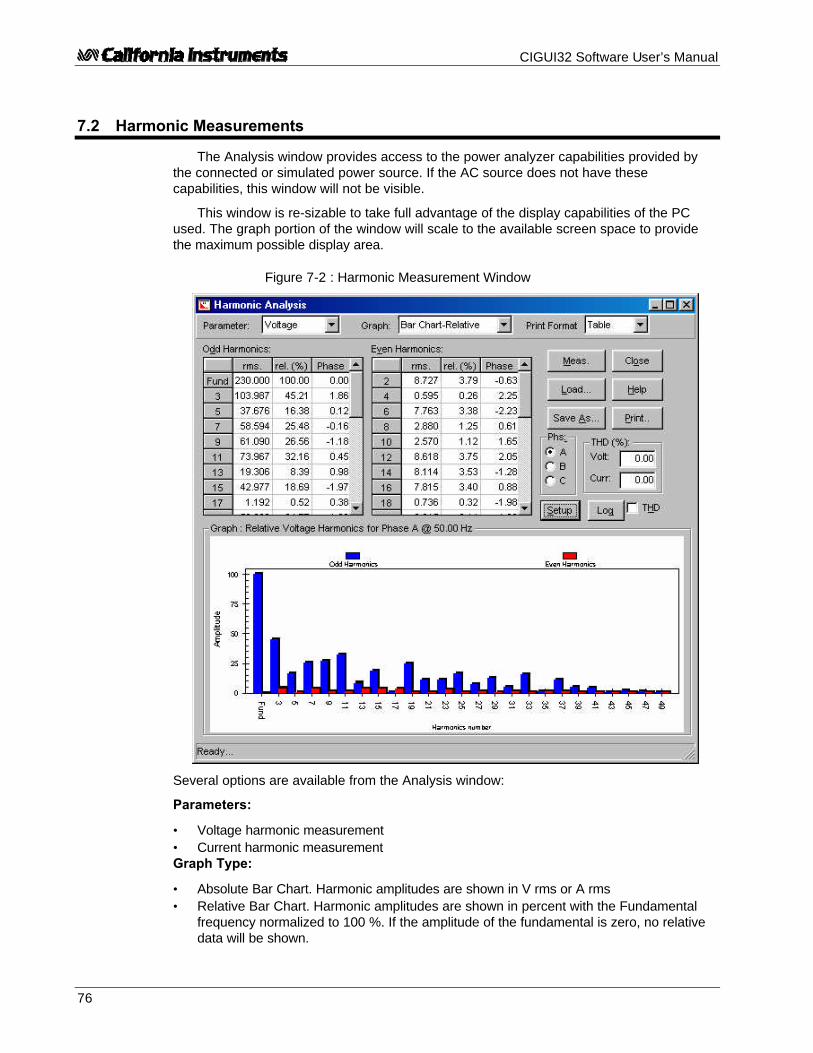
CIGUI32 Software User’s Manual
76
7.2 Harmonic Measurements
The Analysis window provides access to the power analyzer capabilities provided bythe connected or simulated power source. If the AC source does not have thesecapabilities, this window will not be visible.
This window is re-sizable to take full advantage of the display capabilities of the PCused. The graph portion of the window will scale to the available screen space to providethe maximum possible display area.
Figure 7-2 : Harmonic Measurement Window
Several options are available from the Analysis window:
Parameters:
• Voltage harmonic measurement• Current harmonic measurementGraph Type:
• Absolute Bar Chart. Harmonic amplitudes are shown in V rms or A rms• Relative Bar Chart. Harmonic amplitudes are shown in percent with the Fundamental
frequency normalized to 100 %. If the amplitude of the fundamental is zero, no relativedata will be shown.
CIGUI32 Software User’s Manual
77
• Time Domain. This display mode shows a time domain reconstruction of the waveform.(Note that when the HGA is used, there is no phase information available so thewaveform reconstruction is not accurate.)
Print Format:
Harmonic analysis data can be printed in tabular form or graphically. Tabular print outscontain all fundamental data in one A4 (Europe) or Letter (US) size page. Graphicalprintouts contain the type of graph selected under Graph Type. Print outs always containthe date and time the acquisition took place, the fundamental frequency, phase (A, B or C)and parameter (Volt or Current).
Measuring:
Pressing the Meas button start a single acquisition cycle. This cycle can take up to 48seconds depending on the model and interface type used. The progress of the cycle isshown in the status bar at the bottom of the window.
Note: THD measurements are only taken if the “Meas THD” check box is checked.
Saving Measurement Data:
Harmonic measurement data can be saved to disk for future recall or use by otherprograms. This allows records of units under test to be archived. The file extension is“.HMD” which is short for Harmonic Measurement Data. These files are comma separatedvalue ASCII files.
Previously saved data can be recalled using the Load button at any time for display andprinting purposes.
Phase Selection:
Harmonic measurement data is taken on only one phase at a time. The phase selectbox will be enabled if the power source used is in three phase mode. Select the phase youwould like to analyze before pressing the Meas button.
Automatic Data Logging:
If the Disk Log button is pressed, harmonic data measurements are logged to a CSVdisk file using the Data Log Files parameters selected.. Data is recorded in the file selectedusing the Data File dialog box. Data logging will incorporate all phases selected in the DataFile dialog box. You can also specify there if you want phase data to be included in the datalog file or not.
Setup:
The “Setup” button provides access to the Setup dialog which allows you to customizethe look of the graphs and print outs.
CIGUI32 Software User’s Manual
78
7.2.1 Graph Scale and Color Settings
The Setup dialog allows you to change the look of the Bar Graph and Line display. Thesame look will appear when the graph’s are printed. The following options are available:
Bar Colors:
• Absolute• Odd Bar color of the odd harmonics• Even Bar color of the even harmonics
• Relative• Odd Bar color of the odd harmonics• Even Bar color of the even harmonics
Vertical scale:
• Absolute• Auto Scaling is based on actual min. and max. data values• Max User specifies upper limit of vertical axis. Lower limit is always
zero. This can be used to expand very small harmonics.
• Relative• Auto Scaling is based on actual min. and max. data values• Max User specifies upper limit of vertical axis. Lower limit is always
zero. This can be used to expand very small harmonics.
Grid:
Choose from None, Horizontal lines only, Vertical lines only or both horizontal andvertical lines.
Graph printing:
• Black & White: This selection will cause the use of hatch marks to produce a pure black and white printout. This mode is appropriate for old style
dot matrix printers.• Color: This selection will cause colors to be used if a color printer is
selectedor maps the colors to gray scales for monochrome printers. Usethis mode for Laser and Ink Jet printers.
Print Border:
When selected, a border is printed around the graph.

CIGUI32 Software User’s Manual
79
7.3 Harmonic Limit Testing
The Harmonic limit window is a special form of harmonic measurements. Using thiswindow, the user can compare harmonic measurement data against pre-defined limit values.This provides for quick pass or fail determination of a unit under test against a set of knowngood reference data. Limit files can be created using the built in test limit editor and savedto disk. Commonly used limits such as EN/IEC 61000-3-2 harmonic current (only stationaryharmonics can be analyzed and no support for Amendment 14 of EN/IEC 61000-3-2:2000 isprovided) and voltage limits are distributed with the program. The limits can be specified inabsolute or relative terms.
Figure 7-3 : Harmonic Limit Test Window
7.3.1 Limit files
Many applications require testing of harmonic content of either voltage or current.Typical examples are IEC harmonic current emission limits or voltage distortionrequirements imposed on the AC source used to perform these types of test. WhileCalifornia Instruments offers complete IEC compliance test systems (CTS Series), manyapplications can be tested with just the iX Series or iL Series AC source. This is particularlytrue for stationary harmonics. If the unit under test exhibits fluctuation or transitoryharmonics however or testing to the new Amendment 14 of EN 61000-3-2 is required, aCTS system should be used as this requires no-gap acquisition of the current harmonics.

CIGUI32 Software User’s Manual
80
The iX and iL Series AC source can capture stationary harmonics data for both voltageand current. This data can be compared by the CIGUI32 against user defined limits. Severalcommonly used limits are distributed with the CIGUI32 already. Specifically, the followingVoltage or Current harmonic limit files are included with the CIGUI32 for immediate use inthis window:
File name Description
IEC32_ClassA_Steady IEC 61000-3-2 Steady state harmonic current emissionlimits for class A products.
IEC32_ClassB_Steady IEC 61000-3-2 Steady state harmonic current emissionlimits for class B products.
IEC32_ClassC_Steady IEC 61000-3-2 Steady state harmonic current emissionlimits for class C products.
IEC32_ClassD_Steady IEC 61000-3-2 Steady state harmonic current emissionlimits for class D products.
IEC3_Voltage_Distortion_Limits AC Source voltage distortion limits for IEC 61000-3-2 andIEC 61000-4-13 source compliance verification.
7.3.2 Acquiring harmonics measurement data
New harmonic measurement data is acquired each time the Acquire button is pressedor a different phase is selected. Data is compared against specified limits and any valuethat exceeds the set limit is flagged as a failure in red. If none of the measured valuesexceed any of the limits, a green PASS banner is shown in the top left corner of the window.If one or more limits is exceeded, the banner will display FALSE in red.
Selecting a different set of limit values from the Limits drop down box will not result inthe acquisition of new data. Instead, the existing measurement data is compared againstthe newly selected limits and the result of the comparison is displayed.
7.3.3 Editing limit data
In addition to the supplied limit files, the user may set up his own library of harmonic limitfiles using the built in Limit File Editor. To invoke the editor, select and existing limit file,click on the Edit menu and select Harmonic Limits. This will open the selected file in theeditor window.
Harmonic limit files may be used to check voltage or current harmonics againstspecified limits. These limits are contained in Harmonic Limit Files (HLM extension). Limitsmay be set for the fundamental and up to 50 harmonics. It is not necessary to set a valuefor each harmonic however since a No Limit entry can be set.
Limits may be set in a number of different ways to accommodate the various ways inwhich standard bodies set limit values as part of compliance specifications. Specifically, thefollowing limit types are supported:
Type Description

CIGUI32 Software User’s Manual
81
Type Description
No Limit Use this type if no limit is specified for a specific harmonic.
Absolute value This limit is expressed in Amps or Volts directly.
Percent of Fund. This limit is expressed as a percentage of the fundamentalcurrent or fundamental voltage.
mV or mA per Watt This limit is expressed in either mA or mV per Watt. Thismeans the limit is a function of the power consumption of theunit under test. Note that this value is set in mA or mV toprovide greater resolution than would be possible when usingA or V. The EUT power measured is displayed in the main limitwindow for reference.
Percent of Fund * PF This limit is expressed as a percent of the fundamentalmultiplied by the power factor of the unit under test. Usedprimarily to define the third harmonic for class C productsunder the IEC 61000-3-2 harmonic current emissionsstandard.The EUT power factor measured is displayed in the main limitwindow for reference.
Harmonic limit files are saved in ASCII text format for easy import into other programs.The editor is provided as a convenient means of creating or editing harmonic limit files.Other means of creating these files are possible as well.
Harmonic limits files may be printed for documentation purposes using the File, Printmenu entry. To clear the edit grid, use the Edit, Clear menu entry.
After editing the contents, the file may be saved under a different name using the File,Save As menu. A description may be added to each file concerning the type of limitscontained in the limit file to serve as a prompt to the end user.
Once a limit file is selected, the CIGUI32 will acquire the harmonic data from the ACsource and compare each value against its applicable limit. The results are shown in atabular form. The data can be saved to disk or printed using the File menu. A clear PASS orFAIL is shown in the top left corner of the window.
Note that the harmonic limit file also contains the parameter (Volt or Current) to beacquired so it is not possible to apply current limits to a voltage acquisition and vice versa.

CIGUI32 Software User’s Manual
82
7.3.4 Power Level for Class D Current Limits:
For Class D current limit testing, no limits are applied if the EUT power is below the lowpower cut-off point and fixed limits are applied if the EUT power is above the high powercutoff point. The default cutoff power levels are 75 W and 600 W. These values can bechanged if needed by adding the following registry string values at Key:
HKEY_CURRENT_USER\Software\VB and VBA Program Settings\CIGUI32\UserPreferences
String values: ClassDPowerHigh
ClassDPowerLow
The applied power levels for class D limits are displayed when theIEC32_ClassD_Steady.HLM limit file is selected. For any other limit files, these values arenot shown and not applied.
7.3.5 Saving and Printing Harmonic Limit Test Results
The result of a harmonic limit test can be saved to disk using the File Save or File SaveAs menu. All acquired data and applied limits are saved in a file with the extenson HTD(Harmonic Test Data).
Results can also be printed to the selected Windows printer using the File, Print menu.For three phase configurations, the test report will only consist of the selected phase. Toget data for all three phases, each phase must be selected and printed in turn.

CIGUI32 Software User’s Manual
83
7.4 Waveform Measurements
The Waveform measurement window provides access to six channel digital storagescope built-in to the iX Series and iL Series AC power sources. If the AC source you areusing does not have these capabilities, this menu entry will not be visible.
Waveform acquisitions can be used to visualize the timing domain of either voltage orcurrent generated by the AC source. All acquisitions provide 4096 data point samples. Thesample interval varies by model number and phase mode configuration but are displayed inthe top right hand corner of the waveform display window. If it can be changed, a spincontrol will be visible. If it is fixed, the value cannot be changed and is shown for referenceonly. The acquired time window can range between 100 msec and 1 second depending onthe sample rate. An acquisition is either triggered by a transient execution (Trans. Syncmode) or in free run mode. In free run mode, data is acquired when the Meas... button isclicked. In either mode, the trigger delay and trigger phase angle with respect to phase Avoltage can be set.
Several options are available from the Wavform window:
Parameters:
Voltage waveform display Digitized voltage waveform V(t)
Current waveform display Digitized current waveform I(t)
Voltage and Current display Both voltage and current in time a correlateddisplay
Figure 7-4: Timing Waveform Window

CIGUI32 Software User’s Manual
84
Power display Product V(t) * I(t) as a function of time
Three phase Voltage display Digitized phase A,B and C voltage waveform V(t)(Only when using a three phase AC source in three phasemode)
Three phase Current display Digitized phase A,B and C current waveform I(t)(Only when using a three phase AC source in three phasemode)
Graph Type:
Time Domain
Print Format
Waveform data can be printed in both graphical and tabular formats. The graphicalformat is the most obvious format to use. In tabular form, the amount of data printed cancover several pages since each acquired waveform consists of 4096 floating pointnumbers.
Acquisition Modes:
Waveforms can be acquired in one of two ways:
1. Synchronized to a transient program. This requires the user to select a transient liststep number in the transient window. When the transient execution reaches thisstep, a trigger signal is generated to the internal storage scope. The actual triggerpoint can be positioned around this trigger point by setting an offset value in numberof samples (iL Series) or time (iX Series).iL Series:Thus, an offset of -2048 samples means the trigger moment will be in the center ofthe waveform buffer. The maximum pre-trigger delay is -4095 which reflects thewaveform buffer size. The maximum post-trigger delay is +2E+9 or 2 billion samples.If a post trigger delay of more than + 4095 is used, the actual trigger point is nolonger visible. When the synchronized acquisition mode is used, the user cancontrol the sample rate from 25 µseconds to 250 µsecond in 25 µsecond steps. TheFree Run mode is on when the Synchronize with Transient check box is checked.iX Series:The trigger delay can be set from –104 msec in single phase mode to –312 msec inthree phase to + 1000 msec (Port trigger delay). The user can control the samplerate from 25 µseconds to 250 µsecond in 25 µsecond steps on single phase iXsystems and from 75 µseconds to 750 µsecond in 75 µsecond steps on threephase iX systems.
In this mode of operation, an acquisition is always triggered by the execution of atransient program. The waveform window can be left open to toggle to the transientwindow. Clicking on the button will only retrieve the waveform data from theAC source, it will not trigger a new acquisition.
2. Free Run: In free run mode, waveform data is acquired any time the button ispressed. No transient program is required. Free run acquisitions on the iL Seriesalways take place at the highest sample interval. The Free Run mode is on whenthe Synchronize with Transient check box is NOT checked. The trigger delay andphase angle settings remain in effect.

CIGUI32 Software User’s Manual
85
Graph Menu:The waveform graph can be copied to the clipboard if needed for use in other Windows
applications. It is also possible to clear and existing waveform display by selecting the"Clear" entry from the Graph menu. This resets the data for the presently displayed graphmode to zero.
Waveform Data files
Waveform data can be saved to and recalled from disk for later printing or analysis.Waveform data is stored in CSV format with uses a WFD file extension.
Zoom and unzoom
The waveform data display can be zoomed by dragging the mouse while pressing theleft mouse button. This will draw a rectangle. Releasing the mouse button will result in theselected area zooming in. To zoom out to normal magnificaton, double click on the graphwith the left mouse button. The graph may be cleared if needed using the erasor toolbarbutton or from the Graph, Clear menu entry.
Setup
The Setup button provides access to the Setup dialog, which allows you to customizethe look of the graphs and printouts.

CIGUI32 Software User’s Manual
86
7.4.1 Waveform Settings
The Setup dialog allows you to change the look of the waveform display. The same lookwill appear when the waveforms are printed. The following options are available:
Trace Color:
• Color used to draw the waveform on a black background.
Voltage Y Axis scaling:
• Auto Scaling is based on actual min. and max. data values• Max User specifies upper limit of vertical axis. Lower limit is complement of
upper limit.
Current Y Axis scaling:
• Auto Scaling is based on actual min. and max. data values• Max User specifies upper limit of vertical axis. Lower limit is complement of
upper limit.
Trace Buffer Control:
Only available for iX Series models. This section allows you to define a subset of theavailable acquisition buffer for transfer to the CIGUI32 program. Reducing the amount ofdata transfered can speed up the screen update rate, especially when using RS232C.The buffer size can be set in 256 sample steps. The offset determines the first sampleto be transfered. If the full buffer size is selected, the offset has to be 0. If the smallestbuffer size of 256 samples is selected, the offset can be as large as 3840 samples.
Note that older firmware versions of the iX Series (less than version 1.0) do not supportthis buffer sizing capability. The buffer size controls are not provided if the firmwarerevision is less than 1.0.
Grid:
• Choose from None, Horizontal lines only, Vertical lines only or both horizontal andvertical lines.
Graph printing:
• Black & White: This selection will cause the use of hatch marks to produce a pureblack and white printout. This mode is appropriate for old style dotmatrix printers.
• Color: This selection will cause colors to be used if a color printer isselected
or maps the colors to gray scales for monochrome printers. Usethismode for Laser and Ink Jet printers.
• White Background When printing to a color printer, checking this option willreverse the black graph background to white to preserve ink.
Print Border:
When selected, a border is printed around the graph.

CIGUI32 Software User’s Manual
87
7.5 Data Logging
The data logging feature permits both standard and harmonic measurement data to bewritten to disk for archiving, documentation and analysis purposes.
For standard measurements, this capability can be turned on or off by setting a checkmark at the bottom of the measurement window at the “Log data every..” position. Onceenabled, measurements are taken at the interval rate displayed in the text box at the bottomof the measurement window. The minimum logging interval time is 5 seconds. The maximumis 3600 seconds or one hour between recordings.
For harmonic measurements, the data log file set up by the user is used when the “DiskLog” button is clicked instead of the “Meas.” button. Waveform data acquisitions cannot belogged to disk since the data transfer time for each waveform is too long to make thispractical.
7.5.1 Selecting a data file
Figure 7-5 : Measurement Log File Setup Window
The data is stored in a comma-separated value ASCII text file using the path andfilename shown at the bottom of the Measurement window. There may not be enough roomto display the entire path as indicated by leading dots. Data logging filenames can be setusing the Measurements - Data Log Files sub-menu. Selecting this menu displays a dialogbox that allows the file name and file options for both types of measurements to be selected.The file name can be entered directly or selected using the button. If an existing datafile is selected, data will be appended to it if the Append mode is selected. If the Overwritemode is selected, the existing data file will be overwritten with new data.

CIGUI32 Software User’s Manual
88
7.5.2 Selecting the File Mode
Two file modes are supported, append and overwrite. Appendmode is useful for accumulating test data on the same unit undertest but broken up into multiple test sessions. Overwrite is usefulwhen old data is no longer needed or has become invalid andneeds to be replaced while maintaining the same file name.
When selecting an existing data file, the Append mode will cause new data to beappended to the existing data file. When overwrite is selected, data in the existing data filewill be replaced with the new data. When appending data to an existing data file, make surethe selected phases and parameters match those used for the previous data loggingsession or the number of columns in the data file will be different between log sessions.When appending to a new file, the file will be created first so the effect is the same aselecting Overwrite mode.
7.5.3 Selecting the time stamp format
Each data file record entry is automatically time stampedwith the date and time the data was obtained from the ACSource unit. The “time serial number” format is practical whenthe data is to be analyzed or displayed using a spreadsheetprogram such as Excel as this format is identical to that usedby Excel for tracking dates and times. To display a “time serial number” in readable form,use the Cell, format, data, time functions available in Excel. The “time serial number” is afloating point number the integer part of which signifies the number of days past Jan 1,1900. The decimal fraction of the “time serial number” represents the elapsed time from0:00:00 (12:00:00 A.M.) to 23:59:59 and ranges from 0 to 0.99999999 (11:59:59 P.M.).Use the Cell Format function in Excel to display the time serial number as a text string.Using the serial number has the advantage that it is easier to perform math on it. Thedisadvantage is that it is difficult to interpret in other programs that do not support thisformat.
The ASCII string date and time format generates an ASCII string formatted data andtime stamp that can be used with any program.
Example: ASCII String : 8/24/95 15:40:41
Serial number: 34935.65325
The time stamp is always the first column of any data file.
7.5.4 Data File Comments
A comment line can be added to the data file for future reference. This can be usefulwhen trying to analyze data taken in the past. The comment line will be added at the top ofthe data acquisition file unless the selected file already exists in which case any newcomment entered here will be ignored.

CIGUI32 Software User’s Manual
89
7.5.5 Data File Format - Standard Measurements
Data files are saved in plain ASCII text using the common CSV format. These filescontain the following record types :
Record 1: File creation date and user comment lineRecord 2: Field description headerRecord 3-infinity Data records. Data record format is shown below.
Data record format
As such, each measurement cycle produces a single record. Each record consists ofthe following fields :
Table 7-1 : Standard Measurement Data Log File Format
Field name DescriptionTimestamp Date and time of recording for this
recordFrequency Frequency valueVolt A Voltage (rms) for phase ACurrent A Current (rms) for phase APhase A Phase angle with respect to phase A.Power A Real power for phase AAppt.Power A Apparent power for phase APower Factor A Power factor for phase APeak Current A Peak current for phase ACrest Factor A Crest factor for phase ADC Offset A DC offset for phase AVolt B Voltage (rms) for phase BCurrent B Current (rms) for phase BPhase B Phase angle with respect to phase BPower B Real power for phase BAppt.Power B Apparent power for phase BPower Factor B Power factor for phase BPeak Current B Peak current for phase BCrest Factor B Crest factor for phase BDC Offset B DC offset for phase BVolt C Voltage (rms) for phase CCurrent C Current (rms) for phase CPhase C Phase angle with respect to phase CPower C Real power for phase CAppt.Power C Apparent power for phase CPower Factor C Power factor for phase CPeak Current C Peak current for phase CCrest Factor C Crest factor for phase CDC Offset C DC offset for phase CVolt L-L A-C Line to Line voltage A-CVolt L-L A-B Line to Line voltage A-BVolt L-L B-C Line to Line voltage B-C

CIGUI32 Software User’s Manual
90
Note: Any measurements and or phases that are disabled (see section Error! Reference sourcenot found.) will not be entered into the measurement record. As such, a record may notcontain all fields.
A sample data file is shown here as an example. This example uses the serial numbertimestamp format. Only 8 data records are shown. Phase B and C measurements weredisabled and therefore do not show.
#1995-08-24 15:30:27#,"User Comment line goes here""Time_serial","F","V(A)","I(A)","°(A)","W(A)","VA(A)","PF(A)"34935.64615,60.0,125.2,0.21,0.00,28,26,1.00034935.64620,60.0,125.2,0.30,0.00,28,38,1.00034935.64626,60.0,125.2,0.21,0.00,27,26,1.00034935.64633,60.0,125.2,0.30,0.00,28,38,1.00034935.64639,60.0,125.2,0.30,0.00,28,38,1.00034935.64645,60.0,125.2,0.30,0.00,28,38,1.00034935.64650,60.0,125.2,0.30,0.00,28,38,1.00034935.64657,60.0,125.2,0.21,0.00,28,26,1.000
7.5.6 Data File Format - Harmonic Measurements
Data files are saved in plain ASCII text using the common CSV format. These filescontain the following record types :
Record 1: File creation date and user comment lineRecord 2: Field description headerRecord 3-infinity Data records. Data record format is shown below.
Data record format
As such, each measurement cycle produces a single record. Each record consists ofthe following fields :
Table 7-2 : Harmonic Measurement Data Log File Format
Field name DescriptionTimestamp Date and time of recording for this recordPhase Phase indicator “A”, “B” or “C”DC component DC offset Voltagedummy Phase angle of DC (always zero)harmonic 1 Voltage (rms) for fundamentalharmonic 1 Phase angle (degrees) for fundamental
repeats for each harmonicharmonic 50 Voltage (rms) for 50 th harmonicharmonic 50 Phase angle (degrees) for 50th harmonic
If more than one phase is selected, phase information is added as A,B,C and thenrepeats in this sequence.

CIGUI32 Software User’s Manual
91
Note: Any measurements and or phases that are disabled (see section Error! Reference sourcenot found.) will not be entered into the measurement record. As such, a record may notcontain all fields.

CIGUI32 Software User’s Manual
92
A sample data file is shown here as an example. This example uses the ASCII timestamp format. Only 2 data records are shown. Phase B and C measurements were disabledand therefore do not show.
#1996-01-09 22:31:40#,"California Instruments Corporation. AC Source GUI"
"Date","Time","Phase","DC","blank","1","ø1","2","ø2","3","ø3","4","ø4","5","ø5","6","ø6","7","ø7","8","ø8","9","ø9","10","ø10","11","ø11","12","ø12","13","ø13","14","ø14","15","ø15","16","ø16","17","ø17","18","ø18","19","ø19","20","ø20","21","ø21","22","ø22","23","ø23","24","ø24","25","ø25","26","ø26","27","ø27","28","ø28","29","ø29","30","ø30","31","ø31","32","ø32","33","ø33","34","ø34","35","ø35","36","ø36","37","ø37","38","ø38","39","ø39","40","ø40","41","ø41","42","ø42","43","ø43","44","ø44","45","ø45","46","ø46","47","ø47","48","ø48","49","ø49","50","ø50"
01-09-1996,22:31:58,A,0.00E+00,0.00E+00,0.00E+00,0.00E+00,0.00E+00,0.00E+00,0.00E+00,0.00E+00,0.00E+00,0.00E+00,0.00E+00,0.00E+00,0.00E+00,0.00E+00,0.00E+00,0.00E+00,0.00E+00,0.00E+00,0.00E+00,0.00E+00,0.00E+00,0.00E+00,0.00E+00,0.00E+00,0.00E+00,0.00E+00,0.00E+00,0.00E+00,0.00E+00,0.00E+00,0.00E+00,0.00E+00,0.00E+00,0.00E+00,0.00E+00,0.00E+00,0.00E+00,0.00E+00,0.00E+00,0.00E+00,0.00E+00,0.00E+00,0.00E+00,0.00E+00,0.00E+00,0.00E+00,0.00E+00,0.00E+00,0.00E+00,0.00E+00,0.00E+00,0.00E+00,0.00E+00,0.00E+00,0.00E+00,0.00E+00,0.00E+00,0.00E+00,0.00E+00,0.00E+00,0.00E+00,0.00E+00,0.00E+00,0.00E+00,0.00E+00,0.00E+00,0.00E+00,0.00E+00,0.00E+00,0.00E+00,0.00E+00,0.00E+00,0.00E+00,0.00E+00,0.00E+00,0.00E+00,0.00E+00,0.00E+00,0.00E+00,0.00E+00,0.00E+00,0.00E+00,0.00E+00,0.00E+00,0.00E+00,0.00E+00,0.00E+00,0.00E+00,0.00E+00,0.00E+00,0.00E+00,0.00E+00,0.00E+00,0.00E+00,0.00E+00,0.00E+00,0.00E+00,0.00E+00,0.00E+00,0.00E+00,0.00E+00,0.00E+00
01-09-1996,22:32:15,A,0.00E+00,0.00E+00,0.00E+00,0.00E+00,0.00E+00,0.00E+00,0.00E+00,0.00E+00,0.00E+00,0.00E+00,0.00E+00,0.00E+00,0.00E+00,0.00E+00,0.00E+00,0.00E+00,0.00E+00,0.00E+00,0.00E+00,0.00E+00,0.00E+00,0.00E+00,0.00E+00,0.00E+00,0.00E+00,0.00E+00,0.00E+00,0.00E+00,0.00E+00,0.00E+00,0.00E+00,0.00E+00,0.00E+00,0.00E+00,0.00E+00,0.00E+00,0.00E+00,0.00E+00,0.00E+00,0.00E+00,0.00E+00,0.00E+00,0.00E+00,0.00E+00,0.00E+00,0.00E+00,0.00E+00,0.00E+00,0.00E+00,0.00E+00,0.00E+00,0.00E+00,0.00E+00,0.00E+00,0.00E+00,0.00E+00,0.00E+00,0.00E+00,0.00E+00,0.00E+00,0.00E+00,0.00E+00,0.00E+00,0.00E+00,0.00E+00,0.00E+00,0.00E+00,0.00E+00,0.00E+00,0.00E+00,0.00E+00,0.00E+00,0.00E+00,0.00E+00,0.00E+00,0.00E+00,0.00E+00,0.00E+00,0.00E+00,0.00E+00,0.00E+00,0.00E+00,0.00E+00,0.00E+00,0.00E+00,0.00E+00,0.00E+00,0.00E+00,0.00E+00,0.00E+00,0.00E+00,0.00E+00,0.00E+00,0.00E+00,0.00E+00,0.00E+00,0.00E+00,0.00E+00,0.00E+00,0.00E+00,0.00E+00,0.00E+00
7.5.7 Data File Format - Timing Waveforms
Waveform data for both Voltage and Current is stored in a Comma Separated ValueASCII format. A floating-point number is associated with each data point of the waveform.The number of data points is always 4096. This data is preceded by a header whichcontains the acquisition date and time, the parameter type and phase, the trigger position innumber of samples and the sample rate used in microseconds. The following section of a.WFD file shows that this current data was acquired on phase A with a -512 sample pre-trigger delay at 25 µsec sampling rate. Data points are stored in time chronological order.
"04-11-1997 , 08:06:26""Current phase A""-512"255.898375.859685.81207

CIGUI32 Software User’s Manual
93
7.6 Using a Spreadsheet Program
The data file format for data logging files was chosen to be easily used by otherprograms. As such, it can be loaded directly by programs such as excel. The commaseparated fields will automatically be entered in individual columns with each rowrepresenting one measurement cycle. Once imported into Excel, analysis and graphicaltrend data displays are easily generated. Refer to your Excel documentation for details.
The example below illustrates the data sample shown in section Error! Referencesource not found. as it appears when loaded in an Excel spreadsheet. (Column A set toDate_Time format).
Other spreadsheets programs such as Lotus 123 and Quattro can be used in a similarfashion although they do not support the time serial number used by the CIGUI32. Use the
date and time ASCII timestamp instead.
Figure 7-6 : Sample Spreadsheet of Measurement Data

CIGUI32 Software User’s Manual
94
8 Applications
This section covers the optional MIL-STD-704, RTCA/DO-160 / EUROCAE ED-14D andIEC 61000-4 AC line immunity tests that are available for selected model numbers. If yourunit is not equipped with any of these options, the Applications menu will not be visible.Only the options that are installed in or supported by the AC Source unit connected to thePC will be shown on the Applications menu. (Refer to section Error! Reference source notfound.).
In simulation mode (no instrument connected), all test options are available and can beselected from the Applications menu.

CIGUI32 Software User’s Manual
95
8.1 MIL-STD-704
The MIL-STD-704 test option provides a large set of standard tests designed to verifycompliance to the MIL-STD-704 standard. To select the MIL-STD 704 test window, thepower source steady state settings have to meet specific conditions. If these settings arenot correct, an error message is shown displaying the required settings for MIL-STD 704testing. On i Series and iX Series systems, either AC or DC mode can be used. If the ACsource steady state settings are not correct, a dialog will be displayed informing theoperator about the need to set the correct settings.
Once a selection has been made, the user can start test execution by clicking on theStart button in the Test Execution section of the window.
Figure 8-1: MIL-STD 704 Test Window
NOTE: This test requires the presence of the -704 firmware option.

CIGUI32 Software User’s Manual
96
8.1.1 MIL-STD 704 Steady State Settings
The allowable steady state AC or DC settings for MIL-STD 704 testing are:
Mode AC DC DC
Voltage 113 - 118 V RMS 24 - 29 Vdc 260 - 280 Vdc
Frequency 393 - 407 Hz
Phase delta 116° - 124°
Voltage unbalance < 3 V RMS max.
Ripple < 1.5 V max. < 6.0 V max.
Table 8-1: MIL-STD 704 Steady State Settings
The CIGUI32 program will enforce 115 V RMS @ 400 Hz for AC mode and either 28Vdc or 270 Vdc for DC mode before granting access to the MIL-STD 704 test window.
The test window contains a listing of available test steps, allowing you to choose anycombination of the available MIL-STD-704 tests. Both revision D (1980) and revision E(1991) of the test standard are supported and can be selected using the radio buttons onthe left hand side of the test window below the time display field.
After one or more selections have been made, you can start test execution by clickingon the Start button. Once a MIL-STD 704 test is started, clicking on the Abort button canstop it. Since some MIL-STD 704 tests can run for several minutes, this may be important ifyou accidentally selected the wrong test. During test execution, the CIGUI32 program willpoll the Operation Complete status every second to see if the MIL-STD 704 program hasbeen completed. The test progress for each sub-test is displayed in the status bar. Theestimated test duration and time for the end of the test are shown on the right hand side ofthe test window.

CIGUI32 Software User’s Manual
97
8.1.2 Approximate Test Times
Following are the approximate test times for the available test steps. The programtracks progress and displays a progress bar at the bottom of the test window when a test isrunning.
Test Step Test Time
Steady State
Voltage Level 3 min.Modulation 2 min.Unbalance 3 min/phaseRipple 2 min
Phase Unbalance 3 min/phasefor B and C only
Waveform Distortion 2 min.Frequency Level 3 min.
Modulation 4 min.
Transient
Voltage High 6 sec.Low 6 sec
Frequency High 19 secLow 19 sec
Abnormal
Voltage Over 110 sec.Under 100 sec
Frequency Over 19 sec Rev. E 14 sec. Rev D
Under 19 sec Rev. E 14 sec. Rev D.
Emergency
Voltage 3 min.Frequency 3 min.
Table 8-2: MIL-STD 704 Test Times
Test time may change with future firmware upgrades. The GUI program will still workcorrectly in this case but may not show the correct expected test time. Status polling willensure that all tests are completed however.
Note: The MIL-STD 704 window is modal so no other functions of the CIGUI32 program canbe used while this test is running.

CIGUI32 Software User’s Manual
98
8.1.3 Test Report
At the end of test run, a summary test report may be printed on the standard Windowsprinter or to a MS Word document. The report mode is selected from the "Options", "IECReport Setup…" menu entry. The test report contains all selected test options as well asthe start and stop time of the test. Note that this is an immunity test and no data iscollected by the AC source or contained in the test report. Information about the EUT, theoperator or any other data pertinent to this test may be added using the data entry fieldslocated at the bottom of the window.
8.1.4 Test Setup Files
Test selections may be saved to a file for later recall. These test files have a .704extension and are normally saved in the IEC_Test directory under the program's applicationdirectory. It possible to save and retrieve these files from other locations if needed.
8.1.5 Three phase i/iX Controller
When using a three phase i/iX based system, the phase selection allows for either allthree phases or one phase at a time. With this program, it is not possible to run 2 out ofthree phases when performing a MIL-STD 704 test. Test times may be affected by theselected phases. This will be reflected in the test time display on the left-hand side of thetest window.
8.1.6 Revision D, 1980 support
Revision D is provided for back ward compatibility only. When selecting revision D inDC mode at 270 V DC, some restrictions apply. Specifically, the Abnormal and TransientVoltage tests are performed at revision E levels due to DC voltage range limitations of thepower source.

CIGUI32 Software User’s Manual
99
8.2 RTCA/DO-160
The RTCA/DO-160 and EUROCAE ED-14 test option provides a large set of standardtests designed to verify compliance to the RTCA/DO-160 standard. This dialog box containsa set of sub-tests, allowing you to choose any combination of the available DO160 tests.The current version supported is RTCA DO-160 Revision D (including Airbus version) andEUROCAE ED-14D.
To select the DO-160 test window, the AC source steady state settings have to meetspecific conditions. If these settings are not correct, an error message is shown displayingthe required settings for DO-160 testing. On i Series and iX Series systems, either AC orDC mode can be used.
The CIGUI32 program will enforce 115 V RMS @ 400 Hz for AC mode and either 14Vdc or 28 Vdc for DC mode before granting access to the RTCA/DO-160 test window. The230 V mode of operation is not support by the i/iX series at this time, as some of the teststeps require voltage surges above its maximum 300 V range. Also, harmonics currentmeasurements per section 16.6 of EUROCAE ED-14D is not supported by the iX Seriespower source. External measurement equipment must be used to meet this requirement.
Figure 8-2: RTCA/DO-160D Test Window
The DO-160 test window provides a set of option boxes to allow the operator to chooseall tests or any subset of the entire test suite. Once a selection has been made, the usercan start test execution by clicking on the Start button in the Test Execution section of thewindow.
Once a RTCA/DO-160 test is started, it can be stopped through the IEEE-488 interfaceby clicking on the Abort button. Since some RTCA/DO-160 tests can last for up to half anhour, this may be important if you inadvertently selected the wrong test. During testexecution, the CIGUI32 program will poll the Operation Complete status every second tosee if the DO160C program has been completed. The test progress for each sub-test is

CIGUI32 Software User’s Manual
100
displayed in the status bar. The estimated test duration and time for the end of the test areshown on the right hand side of the test window.
NOTE: This test requires the presence of the -160 firmware option.
8.2.1 Approximate Test Times
Following are the approximate test times for the available test steps. The programtracks execution progress and displays a progress bar at the bottom of the test windowwhen a test is running. Airbus mode uses the same test times as DO160.
Test Standard ----> DO-160 DO-160 EUROCAE EUROCAE EUROCAE
Test Step Mode:---> AC Mode DC Mode AC Mode AC Mode DC Mode
Normal State Group 1 Group 2,3Voltage_Freq Min 30 min. 30 min. 30 min. 60 min. 30 min.
Max 30 min. 30 min. 30 min. 60 min. 30 min.Voltage Unbalance 30 min 30 min 30 min 60 min 30 minFrequency Modulation 2 min 2 min 2 minWaveform Distortion 30 min. 30 min. 30 min.Voltage Modulation 2 min. 2 min. 2 min.
DC Under 30 sec 30 secSurge 5 min. 5 min. 5 min. 30s 6 min.30s 6 min.Interrupt (each) 3 sec 3 sec 3 sec 3 sec 3 sec
Frequency Transient 6 min.Variation 6 min.
AbnormalVoltage Min 5 min. 30 min. 15 min. 10 min. 30 min.
Max 5 min. 30 min. 15 min. 10 min. 30 min.Drop 9 sec 9 sec 9 sec 9 sec 9 secSurge 36 sec 36 sec 36 sec 36 sec 36 secDC Low 12 min. 12 min.
Frequency Transient 6 min. 30sEmergency
Voltage_Freq Min 30 min. 30 min. 30 min. 30 min. 30 min.Max 30 min. 30 min. 30 min. 30 min. 30 min.
Voltage Unbalance 30 min. 30 min. 30 min. 60 min. 30 min.
Note: The RTCA/DO-160 window is modal so no other functions of the CIGUI32 programcan be used while this test is running.
8.2.2 Test Report
At the end of test run, a summary test report may be printed on the standard Windowsprinter or to a MS Word document. The report mode is selected from the "Options", "IECReport Setup…" menu entry. The test report contains all selected test options as well asthe start and stop time of the test. Note that this is an immunity test and no data iscollected by the AC source or contained in the test report.Information about the EUT, the operator or any other data pertinent to this test may beadded using the data entry fields located at the bottom of the window.
8.2.3 Test Setup Files
Test selections may be saved to a file for later recall. These test files have a .160extension and are normally saved in the IEC_Test directory under the program's applicationdirectory. It possible to save and retrieve these files from other locations if needed.
CIGUI32 Software User’s Manual
101
8.2.4 Three phase i/iX Controller
When using a three phase i/iX based system (15003iX or 30003iX), the phaseselection allows for either all three phases or one phase at a time. With this program, it isnot possible to run 2 out of three phases when performing a -DO160 test.
Note for CLK system users: Due to the three controller implementation of a clock andlock system, DO 160 tests run in three phase mode will not result in synchronized executionbetween phases when using the firmware option. If the system used is a regular three-phase controller based system, this limitation does not apply.

CIGUI32 Software User’s Manual
102
8.3 EN/IEC 61000-4-11 for i/iX Series with –411 and/or EOS Option only
The CIGUI32 supports two implementations of the IEC 61000-4-11 test standard, onebased on the firmware option available for the i/iX-Series and one implemented in theCIGUI32 program itself that runs on any supported AC source. If you are using a i/iX SeriesAC source, check your configuration window to see if this option is installed. The CIGUI32will automatically choose the right implementation. This section covers the i/iX Seriesfirmware option based implementation. If the AC source you are using is not an i/iX Seriesor is an i/iX Series without the -411 option, refer to section 8.4 instead. If the optionalElectronic Output Switch is present, the –411 option must be installed in the power sourceand this test window will be selected.
This section covers the IEC 61000-4-11 firmware option available for the i/iX Seriesonly. If you are using a different model or did not purchase the IEC 61000-4-11 firmwareoption, refer to the software implementation of the IEC 61000-4-11 test instead. Check yourconfiguration screen to see if this option is installed.
Figure 8-3: IEC 61000-4-11 i/iX Series –411 Option Test window

CIGUI32 Software User’s Manual
103
8.3.1 Voltage Dips and Interruptions Immunity Test
The IEC 61000-4-11 test suite consists of two types of tests:
Dips and Interruptions Simulates short interruptions in AC supply
Voltage Variations Simulates slow changes in AC supply
Each section can be selected for complete execution. The Run All option allows allsteps in the test to be executed in sequence. It is also possible to select a single step. Inthis case, the step parameters can be set by the user. This allows any combination ofparameters to be set.
Note that the IEC 61000-4-11 specification is based on common types of AC linedisturbances found on the European utility network. The number of tests required to performIEC 61000-4-11 tests is not clearly defined so there is room for interpretation. For thisreason, the Run Single option was provided so that individual steps can be set by the user.For more elaborate ‘customized’ IEC 61000-4-11 test sequences, the transient capability ofthe AC source can be used.
8.3.2 Test Results
There is no way for the CIGUI32 to determine the outcome of this test as a cleardefinition of a failure can not be given. The draft standard called out the following possibletest results:
“The test results shall be classified on the basis of the operating conditions andfunctional specifications of the equipment under test, as in the following, unlessdifferent specifications are given by product committees or product specifications.
a) Normal performance within the specification limits
b) Temporary degradation or loss of function or performance which is self-recoverable.
c) Temporary degradation or loss of function or performance which requires operatorintervention or system reset.
d) Degradation or loss of function which is not recoverable due to damage ofequipment (components) or software, or loss of data.
As a general rule, the test result is positive if the equipment shows its immunity, for theduration of the application of the test, and at the end of the tests the EUT fulfills thefunctional requirements established in the technical specification.”
The user has to make this determination by observing the unit under test.
8.3.3 IEC 61000-4-11 Test Reports
The test result and test conditions can be printed to a test report reports. Use the Printbutton or the File, Print menu to run the report. Reports cannot be printed while a test is inprogress. The report format and test report headers can be selected from the Option, IECTest Report menu but needs to be done before opening the IEC 411 test screen. Theselected format (Printer, Text File or MS Word) applies to all IEC immunity tests. MS Wordreports are automatically saved in theC:\Program Files\California Instruments\Cigui32\Reports directory.

CIGUI32 Software User’s Manual
104
8.3.4 Compliance Statement
Based on the hardware specifications of the AC source in use, not all requirements forIEC 61000-4-11 test generators may be met. In particular, the 1 to 5 microsecond rise andfall time called out in the specification is not met by most AC sources. This is unlikely tohave any effect on the outcome of the test however. A unit that fails a voltage dropout witha 200 microsecond rise and fall time will not likely pass the same dropout performed at 5microseconds rise and fall times and vice versa.
Peak Current Test
Also, the 500 Amps inrush current capability is not met. This requirement does not haveto be met if the unit under test does not draw more inrush current than the AC source candeliver. Check your hardware specifications to determine the maximum current capability ofthe source you are using. The peak current measurement takes about 12 minutes and maybe selected by checking the Include peak current test check box.
EOS Option
To meet the rise and fall time requirement as well as the 40 Arms at 40 % of Unom withUnom = 230V, the -EOS (single phase) or -EOS3 (three phase) option is required. The ACcontroller firmware automatically detects the presence of the EOS option. (EOS = ElectronicOutput Switch).
When using the -EOS option, the dip levels will be restricted to 100, 70 and 40 % ofUnom. The CIGUI32 enforces these values automatically.
Three phase i/iX Controller
When using a three phase i/iX based system (15003iX or 30003iX), the phaseselection allows either all three phases or one phase at a time. It is not possible to run 2out of three phases when performing a -411 test.
Note for CLK system users: Due to the three controller implementation of a clock andlock system, 4-11 tests run in three phase mode will not result in synchronized executionbetween phases when using the firmware option. To perform 4-11 tests with synchronizeddips and interruptions on a three phase clock and lock system, the IEC 61000-4-11software implementation is used instead. If the system used is a regular three-phasesystem, this limitation does not apply.

CIGUI32 Software User’s Manual
105
8.4 EN/IEC 61000-4-11 for All Other AC Source Models
The CIGUI32 supports two implementations of the IEC 61000-4-11 test standard, onebased on the firmware option available for the i/iX-Series and one implemented in theCIGUI32 program itself that runs on any supported AC source. If you are using a i/iX SeriesAC source, check your configuration window to see if this option is installed. The CIGUI32will automatically choose the right implementation. This section covers the softwareimplementation. If the AC source you are using is not an i/iX Series with the -411 optionrefer to section 8.3 instead.
Figure 8-4: IEC 61000-4-11 Test window

CIGUI32 Software User’s Manual
106
8.4.1 Voltage Dips and Interruptions Immunity Test
The CIGUI32 software implementation of the IEC 61000-4-11 test suite consists of twotypes of tests:
Dips and Interruptions Simulates short interruptions in AC supply
Voltage Variations Simulates slow changes in AC supply
The user must select the desired test type before executing the test. Since both testtypes require a number of test parameters, it is imperative that at least one “.411” test file ispresent in the CIGUI32 application directory. A “.411” is a Windows INI type file with a .411extension that defines the test parameters and test levels to be used. Test files can beopened from the File, Open menu.
Note that the IEC 61000-4-11specification is based on commontypes of AC line disturbances found onthe European utility network. The testvoltage levels and dip durationsrequired to perform IEC 61000-4-11tests is not clearly defined. Instead,different test levels and durations areallowed for various productcategories. Product committees setthese test levels. For this reason, thetest parameters used by the CIGUI32for the IEC 61000-4-11 test sequences can be specified in the .411 file. This allowsunlimited customization of both voltage interruptions and voltage variations tests. Thisallows for up to 31 sequences of voltage dips at various levels, phase angles and durations.Voltage variations can be defined by level, rise time, fall time and hold time.
Test levels and durations can be edited on screen as well. Note that some parameterssuch as the number of Dips per step and the Gap delay are the same for all steps. (Onlyone parameter is available which applies to all steps.) Changing these values at any stepwill automatically update all other steps.
Once changes have been made, the user will be prompted to save these changes whenthe form is closed. If answered with Yes, the existing .411 file is updated to reflect thechanges made.
Figure 8-5: IEC 61000-4-11 Voltage Variation specification
Fall time Hold time Rise time Delay time
U
Unom
Test
Level(%)

CIGUI32 Software User’s Manual
107
8.4.2 Pausing the Voltage Dip test
During execution of the Voltage Dip portion of the 4-11 test, it may be necessary for theoperator to manually restart the EUT after a voltage drop that causes the EUT to shut downcompletely. Since several drops are to 0 % of Unom and can last for several seconds, theEUT may shut off several times during the test. While most EUT’s will power up bythemselves, some may not. In this case, a negative GapDelay may be specified. When theGUI encounters a negative delay time, it will display a user prompt and pause the 4-11 test.The message that appears in the dialog box can be specified in the .411 test file. A samplesection of the .411 file that invokes this feature is shown here.
UserPrompt = User intervention required. Press OK when ready to continueGapDelay0 = -1
8.4.3 Peak current test
The IEC 61000-4-11 specification calls out source qualifications, which include theneed for the AC source to provide 500 A current of peak current. If the source has a lowerpeak current, an EUT inrush current test can be performed instead. If the EUT inrush currentis less than 70% of the source’s capability, the source qualifies for the test. The GUI offersan optional EUT peak current test to meet this requirement. When selected, the EUT inrushcurrent is measured prior to each test run. If the inrush current exceeds the source’scapability, a warning is issued. The operator has the option of aborting the test or continuingat this point. The result of the peak current test is incorporated in the IEC 61000-4-11 testreport.

CIGUI32 Software User’s Manual
108
8.4.4 Test Results
There is no way for the CIGUI32 to determine the outcome of this test as a cleardefinition of a failure can not be given. The draft standard called out the following possibletest results:
“The test results shall be classified on the basis of the operating conditions andfunctional specifications of the equipment under test, as in the following, unlessdifferent specifications are given by product committees or product specifications.a) Normal performance within the specification limitsb) Temporary degradation or loss of function or performance which is self-recoverable.c) Temporary degradation or loss of function or performance which requires operatorintervention or system reset.d) Degradation or loss of function which is not recoverable due to damage ofequipment (components) or software, or loss of data.
As a general rule, the test result is positive if the equipment shows its immunity, for theduration of the application of the test, and at the end of the tests the EUT fulfills thefunctional requirements established in the technical specification.”
The user has to make this determination by observing the unit under test. At the end ofthe test, the GUI will pop up a dialog box asking the operator to assess the state of theEUT. If the EUT is still functional, the operator may answer Yes when prompted. If not, heshould answer no. The response to this query is incorporated as a PASS or FAIL result inthe test report. For assistance, the operator can select Help to get on-line help on pass andfail criteria.
8.4.5 Measurements
During the test run, both voltage and current are measured at regular intervals(specified by the MeasUpdateRate parameter). This allows the user to determine if the UUTcontinues to operate. There may be effects on the UUT such as reboots or processorlockups that cannot be seen by observing the UUT load current. Frequency is not measuredas it remains at the nominal frequency specified.

CIGUI32 Software User’s Manual
109
8.4.6 IEC 61000-4-11 Test Reports
At the end of a test run, the operator can generate a test report by clicking on the “Printreport” button. IEC 61000-4-11 test reports include all test setup information and testresults. User provided information at the bottom of the 4-11 screen is included as well.
The report format and test report headers can be selected from the Option, IEC TestReport menu but needs to be done before opening the IEC 411 test screen. The selectedformat (Printer, Text File or MS Word) applies to all IEC immunity tests. MS Word reportsare automatically saved in theC:\Program Files\California Instruments\Cigui32\Reports directory.
8.4.7 Compliance Statement
Based on the hardware specifications of the AC source in use, not all requirements forIEC 61000-4-11 test generators may be met. In particular, the 1 to 5 microsecond rise andfall time called out in the specification is not met by most AC sources. This is unlikely tohave any effect on the outcome of the test however. A unit that fails a voltage dropout witha 80 microsecond rise and fall time will not likely pass the same dropout performed at 5microseconds rise and fall times and vice versa.
Also, the 500 Amps inrush current capability is not met. This requirement does not haveto be met if the unit under test does not draw more inrush current than the AC source candeliver. The optional peak current test may be used to satisfy this requirement.

CIGUI32 Software User’s Manual
110
8.4.8 IEC411.411 File Format
IEC411 setup files use a .411 extension. One sample setup file is distributed with theCIGUI32 program. This setup is based on IEC draft standards dated March 15, 1996.Following is a summary of entries and allowable limits. A sample of the original IEC411.411test file shipped with the CIGUI32 is provided as well.
.411 File Format
[IEC-1000-4-11] IEC 61000-4-11 section headerParameters that apply to both Dips and Variations
SeqRepeat = 3 Number of times each voltage fluctuation is repeated. Range 1 to 60.SeqDuration = 10 Time between successive dips and variations. The standard specifies
this time to be no less than 10 seconds.InterSeqDelay = 1 Time between each run of dips or variations. This time should be at least
1 seconds and no more than 60 seconds.MeasUpdateRate =1000
Interval for updating measurement data in milliseconds. Range 100 to60000 milliseconds.Parameters that apply only to Voltage Dips
SeqNumberDips = 21 Number of sets of dips. Each set consists of SeqRepeat dips. Each sethas its own set of three parameters which follow. each parameter has asequence number from 0 through SeqNumberDips-1. They do not haveto be entered in any order.
CycleTime0 = 0.5 For each set number 0 through SeqNumberDips-1, the duration of the dipin AC cycles.
StartPhase0 = 0 For each set number 0 through SeqNumberDips-1, the start phase angleof the dip
TestLevel0 = 0 For each set number 0 through SeqNumberDips-1, the voltage level todip to in % of U nominalParameters that apply to Voltage Variations
FallTimeVar = 2 Voltage fall time in seconds. Must be between 1 and 999 secondsHoldTimeVar = 1 Voltage hold time in seconds. Must be between 1 and 999 secondsRiseTimeVar = 2 Voltage rise time in seconds. Must be between 1 and 999 secondsVarLevel0 = 40 First voltage level to change to in percent of U nominalVarLevel1 = 0 Second voltage level to change to in percent of U nominal

CIGUI32 Software User’s Manual
111
8.4.9 IEC411.411 Sample Files
Following is a listing of the default IEC test files shipped with the CIGUI32 program. Iffor some reason your files are lost or you would like to restore them to their originalcondition, use the values shown here.
IEC411.411 File Content:
[IEC-1000-4-11]'Parameters used for both testsSeqRepeat = 3SeqDuration = 10InterSeqDelay = 1MeasUpdateRate = 1000'Voltage Dips ParametersSeqNumberDips = 21CycleTime0 = 0.5StartPhase0 = 0TestLevel0 = 0CycleTime1 = 0.5StartPhase1 = 180TestLevel1 = 0CycleTime2 = 1StartPhase2 = 0TestLevel2 = 0CycleTime3 = 5StartPhase3 = 0TestLevel3 = 0CycleTime4 = 10StartPhase4 = 0TestLevel4 = 0CycleTime5 = 25StartPhase5 = 0TestLevel5 = 0CycleTime6 = 50StartPhase6 = 0TestLevel6 = 0CycleTime7 = 0.5StartPhase7 = 0TestLevel7 = 40CycleTime8 = 0.5StartPhase8 = 180TestLevel8 = 40CycleTime9 = 1StartPhase9 = 0TestLevel9 = 40CycleTime10 = 5
StartPhase10 = 0TestLevel10 = 40CycleTime11 = 10StartPhase11 = 0TestLevel11 = 40CycleTime12 = 25StartPhase12 = 0TestLevel12 = 40CycleTime13 = 50StartPhase13 = 0TestLevel13 = 40CycleTime14 = 0.5StartPhase14 = 0TestLevel14 = 70CycleTime15 = 0.5StartPhase15 = 180TestLevel15 = 70CycleTime16 = 1StartPhase16 = 0TestLevel16 = 70CycleTime17 = 5StartPhase17 = 0TestLevel17 = 70CycleTime18 = 10StartPhase18 = 0TestLevel18 = 70CycleTime19 = 25StartPhase19 = 0TestLevel19 = 70CycleTime20 = 50StartPhase20 = 0TestLevel20 = 70'Voltage Variation ParametersFallTimeVar = 2HoldTimeVar = 1RiseTimeVar = 2VarLevel0 = 40VarLevel1 = 0

CIGUI32 Software User’s Manual
112
8.5 EN/IEC 61000-4-13 Harmonics and Interharmonics Immunity Test
The IEC 61000-4-13 Harmonics and Interharmonics immunity test implementation in theCIGUI32 is based on a draft version of the IEC 61000-4-13 standard. Changes to this draftare possible before it becomes an official standard. This test is offered as a convenienceand does require the presence of the –413 option on the iX Series AC power source. If thepresence of this option is not detected, this window will not be available.
Test parameter files are distributed with the program in the IEC_Test directory. These413 test files can be opened from the File Open menu and edited on screen if desired.Changes can be changed using the same (File, Save) or a different file name (File, SaveAs). These files have a “.413” extension. More than one .413 file may reside in theworking directory. The operator may select the one to run from the File, Open dialog.
Versions of the CIGUI32 below 1.00 do not fully implement this option yet. The firstcomplete release of the CIGUI32 including IEC 61000-4-13 will be version 1.00. If you areusing an older version, check the California Instruments’ web site for an update.
Figure 8-6 : IEC 61000-4-13 Test Window
The IEC 61000-4-13 Harmonics and Interharmonics test offers range of sub-tests anduser options. We recommend you familiarize yourself with the actual standard document.IEC standards are available through www.iec.ch.

CIGUI32 Software User’s Manual
113
8.5.1 Test Flow and Test Types
The IEC 61000-4-13 standard specifies the following test flow diagram.
Figure 8-7: IEC 61000-4-13 Test Fow
The operator has to select the appropriate test flow based on the test result of theindividual test steps. The IEC 61000-4-13 test suite consists of four types of tests:
Test Type Description
Flat top Curve Simulates specific waveform at the nominal voltage and frequency
OverSwing Curve Simulates specific waveform at the nominal voltage and frequency
Frequency Sweep Simulates frequency swept or stepped at a rate no less than 5 minutesper decade
Individual harmonics &Interharmonics
Simulates sinusoidal voltage superimposed on the fundamental voltagefor 5 second at each frequency in a range from 2X to 40X fundamental
Table 8-3: IEC 61000-4-13 Test Types

CIGUI32 Software User’s Manual
114
The user must select the desired EMC Class and test type before executing the test. Ifchoosing class X, the user can change any parameters but the levels have to be at least ashigh as those for Class 2. The total test time using the default dwell times are as follows:
Test Step Test Time
Flat Top Curve test: Dwell time = 120 secPause time = 5 sec
OverSwing Curve test: Dwell time = 120 secPause time = 5 sec
Frequency Sweep test: Dwell time = 300 sec (per decade) *2.5 = 750 sec
Individual harmonics: Dwell time = 5 sec (per harmonic) * 40 = 200 secPause time = 1 sec (per harmonic * 40 = 40 sec
Interharmonics: Dwell time = 5 sec (per harmonic) * 147 = 735 secPause time = 1 sec (per harmonic) * 147 = 147 sec
Total time = 1480 sec ~ 36 minutes.
Table 8-4: IEC 61000-4-13 Test Times
8.5.2 Available Control and Display Tabs
The following Tabs are available for setting test options and displaying data during thetest. These Tab controls are located along the top of the IEC 61000-4-13 test window.
Tab Function
Test Setup User selected test options, EUT classes and test steps
Waveforms Flat top curve and Over swing curve definitions
Test Levels Sweep frequency ranges and test levels
Voltage THD AC Source voltage distortion monitor display
Waveform Display AC Source measured output waveform display
Resonance Points EUT current as a function of frequency and resonance pointsummary.
Table 8-5: IEC 61000-4-13 Control Tabs
The buttons on the left-hand side of the window may be used to start and stop a test runand print a test report.
Test parameters for Class X EUT's may be stored on and loaded from disk. This can bedone using the File, Save and File, Open menus.
The results of a frequency sweep may be saved to disk for later recall as well. Datafiles have a .dat extension to distinguish them from a test setup file. (.413 extension) TheLoad and Save Data entries in the File menu are used for this purpose.

CIGUI32 Software User’s Manual
115
8.5.3 Test Setup
The Test Setup Tab contains several controls that allow the user to configure the IEC61000-4-13 test to be run on the EUT. The various settings are as follows:
Parameter Description
Phase mode The available phase mode is shown in the top right corner andcannot be changed. For single-phase systems, phase A is alwaysused as it is the only phase. For three phase systems, all stimuli areapplied to all three phases..
EUT EMC Class The test standard distinguishes between four classes of EUT, class1 through 3 and a user defined class X. The user must select class1, 2, 3 or X. Class X levels can be set in the Test levels Tab butmust be equal than or higher than class 3 levels.
Nominal Settings These values are normally obtained from the AC source's steadystate setting when the test window is opened. They can bechanged before running a test if needed. Note however thanfrequencies other than 50 or 60 Hz are not covered by the teststandard.
Test Step Selection There are four main test categories that may be selected. Consultthe test standard for details on each step. Any combination ofthese four choices can be made.
Test Options Prompt for EUT status: When checked, the program will prompt theoperator for a Pass or Fail determination after each test stepselected in the Test Step Selection box has been run. If this optionis turned off, all test will be run and this dialog will only appear whenall test are completed.IEC 725 Reference Impedance: If needed, the IEC 725 Flickerreference impedance may be used during the IEC 61000-4-13 test.When this option is checked, the iX Series will use itsprogrammable impedance to implement the required referenceimpedance. Note that this capability may not be supported on all iXSeries configurations.Voltage THD: When checked, the test program performs an ACSource voltage distortion pre-test and displays the result in theVoltage THD Tab.Source Regulation: When checked, the test program will checkedthe AC Source output voltage regulation with the EUT connected toensure the AC source meets the test standard requirements.
User Data The fields at the bottom of the Tab may be used to enterinformation on the person or entity performing the test, the EUT andany other comments that may be relevant. This information will beincorporated in the test report.
Table 8-6: IEC 61000-4-13 Test Setup Parameters
User selected EUT Class, test steps, options and nominal values are all included on theIEC 61000-4-13 test reports.

CIGUI32 Software User’s Manual
116
8.5.4 Test Waveforms
The Waveforms Tab may be used to preview the Class 2 and Class 3 Flat top andOverswing waveforms. For class X, the waveform parameters may be entered in thecontrols to the left of the waveform display. Dwell times and pause times may be set for allclasses.
Figure 8-8: IEC 61000-4-13 Test Waveforms
Note that this Tab is only relevant if either the Flat Top or Overswing test steps areselected in the Test Setup Tab.

CIGUI32 Software User’s Manual
117
8.5.5 Test Levels
The Test Levels Tab may be used to preview the Class 2 and Class 3 frequency rangesand test levels. For class X, this information may be edited. Dwell times and pause timesmay be set for all classes. The following minimum and maximum values (in seconds) fordwell and pause times apply. Note that these values are queried from the AC source ifpresent and may change if the firmware on the AC source is updated. As default, thesetimes are set to their minimum values.
Test Type Parameter Minimum Maximum
Sweep Frequency Dwell 300 3600
Interharmonics Dwell 5 600Pause 1 60
Harmonics Dwell 5 600Pause 1 60
Table 8-7: IEC 61000-4-13 Min and Max Test Times

CIGUI32 Software User’s Manual
118
8.5.6 Voltage Distortion
This is a data display Tab only. When selected in the test options, this Tab display thevoltage distortion of the AC voltage supplied by the AC Source as measured at the EUT.The individual voltage harmonics must be below the IEC test standard levels set forth in IEC61000-4-13. The test software checks against these limits and displays a PASS or FAILresult in both the Test Setup Tab and this Tab.
Figure 8-9: IEC 61000-4-13 Voltage Distortion Display
The result of the V THD check is included in the IEC 61000-4-13 Test report. Testresults may be printed to the default Windows printer using the print button or the File, Printmenu.

CIGUI32 Software User’s Manual
119
8.5.7 Waveform Acquisition and Display
This Tab displays the voltage waveform as captured at the EUT by the iX Series' dataacquisition system. This information is updated every couple of seconds and allows theuser to monitor the stimulus applied to the EUT. This TAB is only used for display purposesand contains no user controls.
Figure 8-10: IEC 61000-4-13 Waveform Acquisition Display

CIGUI32 Software User’s Manual
120
8.5.8 Resonance Points
The resonance points Tab displays the EUT current as a function of the harmonic andinterharmonic frequencies applied to the EUT during the test. This information is displayedboth numerically in the table on the left and graphically in the chart on the right. Thosepoints that meet the criteria for a resonance point are listed in the table directly below thegraph. Note that there may not be any resonance points on a given EUT. In that case, thistable will be empty. The total number of resonance points found is shown between thegraph and the resonance point table.
Figure 8-11: IEC 61000-4-13 Resonance Data display
The are no user controls or settings on this Tab as it is used for data display only. Testresults may be printed to the default Windows printer using the print button or the File, Printmenu. Resonance data may be saved to disk for later recall using the File menu Save Dataand Load Data entries. Do not confuse these menu entries with the File Open and Saveentries which are used for saving and recalling setups.

CIGUI32 Software User’s Manual
121
8.5.9 Test Results
There is no way for the CIGUI32 to determine the outcome of this test, as a cleardefinition of a failure can not be given. The draft standard calls out the following possibletest results:
“The test results shall be classified on the basis of the operating conditions and functionalspecifications of the equipment under test, as in the following, unless different specifications aregiven by product committees or product specifications.
a) Normal performance within limits specified by the manufacturer, requestor or purchaser
b) Temporary loss of function or degradation of performance which ceases after thedisturbance ceases, and from which the equipment under test recovers its normalperformance, without operator intervention.
c) Temporary loss of function or degradation of performance, the correction of which requiresoperator intervention.
d) Loss of function or degradation of performance which is not recoverable, owing to damageto hardware or software, or loss of data.
As a general rule, the test result is positive if the equipment shows its immunity, for the duration ofthe application of the test, and at the end of the tests the EUT fulfills the functional requirementsestablished in the technical specification.”
The user has to make this determination byobserving the unit under test. At the end of thetest, the GUI will pop up a dialog box asking theoperator to assess the state of the EUT. Thisprompt can be selected to appear after each sub-test as by setting the "Prompt operator for EUTStatus after each test step" option. The operatormay answer Yes when prompted. If not, he should answer no. The response to this query isincorporated as a PASS or FAIL result in the test report.
8.5.10 IEC 61000-4-13 Test Reports
At the end of a test run, the operator can generate a test report by clicking on the “PrintReport” button or using the File, Print menu. IEC 61000-4-13 test reports include all testsetup information, test data and test results. The number of pages ranges from 5 to 9depening on phase mode selected.
The report format and test report headers can be selected from the Option, IEC TestReport menu but needs to be done before opening the IEC 413 test screen. The selectedformat (Printer, Text File or MS Word) applies to all IEC immunity tests. MS Word reportsare automatically saved in theC:\Program Files\California Instruments\Cigui32\Reports directory.

CIGUI32 Software User’s Manual
122
8.6 EN/IEC 61000-4-14 Voltage Fluctuations Immunity Test
The EN61000-4-14 implementation in the CIGUI32 is based on the EN61000-4-14standard dated 1999-02 and Amendment 1, dated 2001-07. Test levels and times can bechanged if needed through the use of one or more filename.414_Fluc files in the IEC_Testdirectory. These 414 test files can be opened from the File Open menu and edited onscreen if desired. Changes made can be saved using the same (File, Save) or a differentfile name (File, Save As). These files have a “.414_Fluc” extension. More than one.414_Fluc file may reside in the working directory. The operator may select the one to runfrom the File, Open dialog.
Figure 8-12: IEC 61000-4-14 Test window

CIGUI32 Software User’s Manual
123
8.6.1 Test Setup
The following parameters and controls are available for executing the IEC 61000-4-14test:
Nominal voltage Opening this window will set this parameter to the present steady statevoltage setting of the AC source. If required, a new value can beentered for use during the test. At the end of the test, the AC source willremain at this voltage level. If needed, the program will switch the ACsource to the high voltage range and close the output relay when the testis started.
Nominalfrequency
Opening this window will set this parameter to the present steady statefrequency setting of the AC source. If required, a new value can beentered for use during the test. At the end of the test, the AC source willremain at this frequency.
UUT Class The EUT class determines the test levels used. Class selection is doneby loading the correct class file from disk.
Phase Mode The phase mode is determined by the AC source configuration. Thismode cannot be changed from this window. To change phase mode,close this window and use the main front panel control window to selectthe desired phase mode first.
Run Starts the IEC 61000-4-14 test using the parameters set by the user.Test progress is shown at the bottom of the window. The sequencenumbers shown correspond to those in the illustration.
Abort Aborts test in progress.
8.6.2 Test sequence
The test sequence implemented bythis test consists of a series of voltagefluctuations consistent with commonlyfound phenomena on the public utilitypower grid. The objective of this test isto evaluate a product for immunity fromsuch fluctuations. Fluctuations arerepeated 3 times (specified bySeqRepeat) and last for 5 secondseach. (specified by SeqDuration).
Two voltage changeimplementations called out in the draft standard are supported:
1. Five Period Discrete Steps: Each fluctuations consists of stepping the voltage up ordown in five steps of one signal period each (20 msec for 50 Hz, 16.6 ms for 60 Hz)and holding the voltage at this altered level for a 2 second period and stepping itback up or down to its nominal value. This sequence is repeated 3 times and thustakes 3 * 5 = 15 seconds.
2. Quarter Period Slew: The voltage is ramped up starting at 90° on phase A for aperiod of 0.25 cycles to the test level. It is held for a 2 second period and slewedback using the same 0.25 cycle period and held for a total of 5 seconds. Thissequence is repeated 3 times and thus takes 3 * 5 = 15 seconds.
The Level repeat value may be changed by the user to a value other than 3. A timedelay of 60 seconds (specified in the parameter table) is inserted between each sequenceof voltage fluctuations. Voltage is changed both up and down from the nominal value. Next,the nominal voltage is changed by subtracting an offset (specified by Offset) and a positive
Figure 8-13: IEC 61000-4-14 Voltage fluctuation specification
T = 5 sec
t = 2 sect = 5 periods
U
Unom
U5
period = 1/f nom

CIGUI32 Software User’s Manual
124
delta voltage sequence is ran three times again. Finally, the nominal voltage is changed byadding the offset value and a negative delta voltage sequence is ran three times. Thisresults in a total of 12 sequences as shown in the diagram. The total test time using thedefault test parameters called out in the draft specification equals 12 * 75 sec = 15 minutes.The test can be aborted by clicking on the Abort button.
Unom(%)
Test Level(%)
LevelRepeat
Delay Repeat
100 8 3 60 1
Table 8: EN61000-4-14 Test Sequence
Note that the sequence of voltage changes is different if the Unom is at 100 % than at anyother value. At 100 % Unom, the voltage changes occur in both positive and negativedirections (alternating). If the test level (%) is set to a negative value and Unom is 100 %, thevoltage changes are reversed.
These parameters can be entered on screen by the operator or loaded from disk. Toload a new test or test class, select the File, Open menu. The default location for IEC testfiles is:
C:\Program Files\California Instruments\Cigui32\IEC_Test
The following four EN61000-4-14 test files are distributed with the CIGUI32 program:
File Name Test Class
Generic IEC 1000-4-14 Test Class 2.414_Fluc Class 2
Generic IEC 1000-4-14 Test Class 3.414_Fluc Class 3
The user may create as many test files as desired using the data entry grid. Changesmade can be saved using the File, Save As… menu entry.

CIGUI32 Software User’s Manual
125
8.6.3 Test Levels
In Annex B of the draft standard, the EUT operating environment classifications aredefined based on IEC 1000-2-4. The classifications are as follows:
Class Environment
Class 1 Applies to protected supplies with compatibility levels lower than public networklevels. It relates to the use of equipment, which is very sensitive to disturbances in thepower supply, for instance the instrumentation of technological laboratories, someautomation and protection equipment, some computers etc. This equipment isnormally supplied by protected supplies such as uninterruptible power supplies, filersor surge suppressors.
Class 2 Applies to points of common coupling (PCCs for consumer systems) and in-plantpoints of common coupling (IPCs) in the industrial environment in general. Thecompatibility levels in this class are identical to those of public networks.
Class 3 Applies only to IPCs in industrial environments. It has higher compatibility levels thanthose of class 2 for some disturbance phenomena. This class should be consideredwhen any of the following conditions are met:- a major part of the load is fed through converters- welding machines are present- large motors are frequently started- loads vary rapidly
Test levels are specified for class 2 and 3 only. Class X test levels may be defined byspecific product standards.
Environment Class Unom (Nominal Voltage) Unom + 10 % Unom - 10 %
Class 1 no test required no test required no test required
Class 2 ± 8 % Unom - 8 % Unom + 8 % Unom
Class 3 ± 12 % Unom -12 % Unom + 12 % Unom
Class X Open but must be higherthan Level 2
Open but must behigher than Level 2
Open but must behigher than Level 2
8.6.4 Test Results
There is no way for the CIGUI32 to determine the outcome of this test as a cleardefinition of a failure can not be given. The draft standard called out the following possibletest results:
“The test results shall be classified on the basis of the operating conditions and functionalspecifications of the equipment under test, as in the following, unless different specifications aregiven by product committees or product specifications.
a) Normal performance within limits specified by the manufacturer, requestor or purchaserb) Temporary loss of function or degradation of performance which ceases after the
disturbance ceases, and from which the equipment under test recovers its normalperformance, without operator intervention.
c) Temporary loss of function or degradation of performance, the correction of which requiresoperator intervention.
d) Loss of function or degradation of performance which is not recoverable, owing to damageto hardware or software, or loss of data.

CIGUI32 Software User’s Manual
126
As a general rule, the test result is positive if the equipment shows its immunity, for theduration of the application of the test, and at the end of the tests the EUT fulfills the functionalrequirements established in the technical specification.”
The user has to make this determination by observing the unit under test. At the end ofthe test, the GUI will pop up a dialog box asking the operator to assess the state of theEUT. If the EUT is still functional, the operator may answer Yes when prompted. If not, heshould answer no. The response to this query is incorporated as a PASS or FAIL result inthe test report.
8.6.5 IEC 61000-4-14 Test Reports
At the end of a test run, the operator can generate a test report to the selectedWindows printer by clicking on the “Print report” button or using the File, Print menu. IEC61000-4-14 test reports include all test setup information and test results. User providedinformation at the bottom of the 4-14 screen is included as well.
The report format and test report headers can be selected from the Option, IEC TestReport menu but needs to be done before opening the IEC 414 test screen. The selectedformat (Printer, Text File or MS Word) applies to all IEC immunity tests. MS Word reportsare automatically saved in theC:\Program Files\California Instruments\Cigui32\Reports directory.

CIGUI32 Software User’s Manual
127
8.7 EN/IEC 61000-4-17 DC Ripple Immunity Test
This section covers testing a device for compliance with the IEC 61000-4-17 DCVoltage Ripple test standard. This test is supported through the CIGUI32 AC source controlprogram. This test is only supported on iX Series AC&DC Power Sources.
Figure 8-14: IEC 61000-4-17 DC Ripple Test Window
The IEC 61000-4-17 implementation in the CIGUI32 is based on the IEC 61000-4-17standard dated 1999-06 and Amendment 1, dated 2001-07. Test levels and ripplefrequency can be changed if needed or set to one of the pre-defined test levels.

CIGUI32 Software User’s Manual
128
8.7.1 Test Setup
The following parameters and controls are available for executing the IEC 61000-4-17test:
Control / Field Description
Nominal DC voltage This is the rated nominal DC supply voltage to the EUT. Both a highand low DC voltage range can be specified as well. When selected,the test will run at the selected voltage levels. This can anycombination of nominal, high and low.
Line frequency This sets the nominal AC line frequency. The ripple frequency will be amultiple of the AC Line frequency.
Output Select For three phase systems, the output select enables one of threeoutputs or all three. The default is channel (phase) A.
EUT Test Levels The test levels used are determined by the EUT class. Available levelsare 2, 5, 10 or 15 %. A user defined test level from 0 to 25 % may beset as well.
Ripple Frequency This fields sets the multiplier for the ripple frequency. Availablesettings are 1, 2, 3 and 6. A user defined multiplier is available as well.
Test Time The default test time is 10 minutes. If more than one DC Voltage levelis selected, the test time increases with this amount for each selectedlevel. The test time can be set as low as 1 minute or as high as 9999min.
Start Starts the IEC 61000-4-17 test using the parameters set by the user.Test progress is shown at the bottom of the window. The sequencenumbers shown correspond to those in the illustration.
Stop Aborts test in progress.
8.7.2 Test Sequence
The test sequence implemented by this test consists of the application of an AC rippleof specified peak to peak value in percent of the DC voltage at a frequency determined bythe multiplier times the AC Line frequency for a set period of time.
The ripple waveform consists of a sinusoidal linear waveshape as in section 8.7.3. Theobjective of this test is to evaluate a product for immunity from such ripple.
Note that the first time a test is started, the required special waveforms have to bedownloaded to the power source. This process takes some time, especially when using theRS232C interface. If there are not at least 10 user waveform registers available, an errormessage (Memory Full) will be generated. It will be necessary to delete one or more customwaveforms or switch to a different waveform group to make 10 registers available.
When the IEC 61000-4-17 test window is closed, these special waveforms are deleted.

CIGUI32 Software User’s Manual
129
8.7.3 Waveform Display
The DC output waveform is acquired at regular intervals during the test and can bedisplayed by selecting the Waveform Display tab.
Figure 8-15: IEC 61000-4-17 Waveform Acquisition Window
8.7.4 Test Results
There is no way for the CIGUI to determine the outcome of this test as a clear definitionof a failure can not be given. The standard called out the following possible test results:
“The test results shall be classified on the basis of the operating conditions and functionalspecifications of the equipment under test, as in the following, unless different specifications aregiven by product committees or product specifications.
a) Normal performance within the specification limits
b) Temporary degradation or loss of function or performance which is self-recoverable.
c) Temporary degradation or loss of function or performance which requires operatorintervention or system reset.
d) Degradation or loss of function which is not recoverable due to damage of equipment(components) or software, or loss of data.
As a general rule, the test result is positive if the equipment shows its immunity, for theduration of the application of the test, and at the end of the tests the EUT fulfills the functionalrequirements established in the technical specification.”

CIGUI32 Software User’s Manual
130
The user has to make this determination by observing the unit under test. At the end ofa test run, the following dialog box is displayed. Click on the Help button to display thepass/fail criteria shown above.
8.7.5 User Observations
Figure 8-16: IEC 61000-4-17 User Observation Data Entry Window
The CIGUI32 provides a data entry window for the operator. Observations made aboutthe EUT can be entered in this window before, during and after a test run. Any informationentered by the operator in this window will be incorporated in the test report when printed.
8.7.6 Report Format- 417 Test Files
The 417 test module produces a test report when the Print Report button is clicked. Thereport format and test report headers can be selected from the Option, IEC Test Reportmenu but needs to be done before opening the IEC 417 test screen. The selected format(Printer, Text File or MS Word) applies to all IEC immunity tests. MS Word reports areautomatically saved in theC:\Program Files\California Instruments\Cigui32\Reports directory.
8.7.7 Saving and Loading Test Setups
Frequently used test setups can be save to disk by using the File, Save or File Save Asmenu entries. Setup files for IEC 61000-4-17 tests have a ".417" file extension. To select apreviously saved test setup, use the File, Open menu entry and select the desired file fromthe file open dialog.
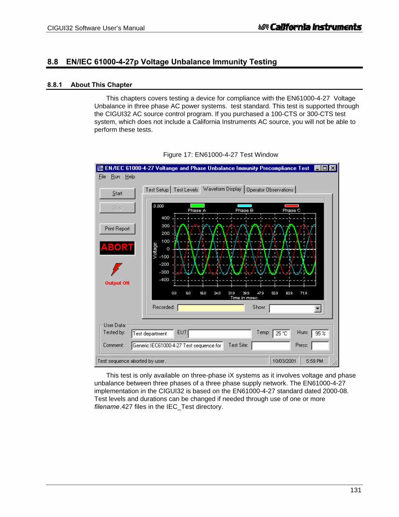
CIGUI32 Software User’s Manual
131
8.8 EN/IEC 61000-4-27p Voltage Unbalance Immunity Testing
8.8.1 About This Chapter
This chapters covers testing a device for compliance with the EN61000-4-27 VoltageUnbalance in three phase AC power systems. test standard. This test is supported throughthe CIGUI32 AC source control program. If you purchased a 100-CTS or 300-CTS testsystem, which does not include a California Instruments AC source, you will not be able toperform these tests.
This test is only available on three-phase iX systems as it involves voltage and phaseunbalance between three phases of a three phase supply network. The EN61000-4-27implementation in the CIGUI32 is based on the EN61000-4-27 standard dated 2000-08.Test levels and durations can be changed if needed through use of one or morefilename.427 files in the IEC_Test directory.
Figure 17: EN61000-4-27 Test Window

CIGUI32 Software User’s Manual
132
8.8.2 Test Setup
The required IEC 61000-4-27 test parameters must be entered in the test data entrygrid before running a test. Previously stored test files can be loaded from the File, Openmenu. Test files use a .427 file extension and only files with this extension can be loaded.
The CIGUI32 is distributed with a pre-defined test parameter files for the generic IEC61000-4-27 product classes 2 and 3. Additional test parameter files e.g. for test level x, canbe created by the user by editing the data entry grid and saving the new data under a userspecified name.
The following parameters and controls are available for executing the IEC 61000-4-27test:
Field / Control Description
Nominal voltage Opening this window will set this parameter to the present steady statevoltage setting of the AC source. If required, a new value can be enteredfor use during the test. At the end of the test, the AC source will remain atthis voltage level. If needed, the program will switch the AC source to thehigh voltage range and close the output relay when the test is started.
Nominal frequency Opening this window will set this parameter to the present steady statefrequency setting of the AC source. Available selections are 50 Hz or 60Hz. At the end of the test, the AC source will remain at this frequency.
EUT Class The EUT class determines the test levels used.
Test number Allows selection of one or more test numbers. If all test numbers areselected, they will be executed in sequential order.
Performance Criterion This selection will be used to indicate in the test report how the outcomeof the test was evaluated. The criteria are explained here.
Execution Parameters Number of sequences to run:A number of one indicates that the test level selected will be run one timeper phase rotation for a total of 3 times. A number greater than one willresult in repeating the same phase rotation that many times. Valid rangefor the sequence repeat field is 1 through 3.
Delay between sequences in minutes:A delay of 3 minutes minimum is required between tests. This value maybe extended if desired.
Pre-test delay in seconds:Time to wait in seconds between applying power to EUT and starting thefirst test sequence.
Phase Mode This test is only valid when the power system is in three-phase mode sono phase mode selection is available. The phase mode is always threephase.
Start Starts the EN61000-4-27 test using the parameters set by the user. Testprogress is shown at the bottom of the window. The sequence numbersshown correspond to those in the illustration.
Stop Aborts test in progress.
All IEC 61000-4 tests require setting of the rated nominal voltage and frequency of theEUT. The nominal values must be entered in the Test Setup Vnom and Fnom data fieldsbefore starting a test. When the IEC 61000-4 test windows is first opened, the present AC

CIGUI32 Software User’s Manual
133
source settings are automatically loaded as the nominal values. These values areoverridden by selecting each data entry field and typing in a new value or by loading a testparameter file from the File, Open menu. Thus, test data file also contain the nominalvoltage and frequency values to be used.
8.8.3 Equipment Classifications
In Annex B of the standard, the EUT operating environment classifications are definedbased on IEC 61000-2-4. The classifications are as follows:
Class 1 Applies to protected supplies with compatibility levels lower than public networklevels. It relates to the use of equipment, which is very sensitive to disturbances inthe power supply, for instance the instrumentation of technological laboratories,some automation and protection equipment, some computers etc. This equipmentis normally supplied by protected supplies such as uninterruptible power supplies,filers or surge suppressors.
Class 2 Applies to points of common coupling (PCCs for consumer systems) and in-plantpoints of common coupling (IPCs) in the industrial environment in general. Thecompatibility levels in this class are identical to those of public networks.
Class 3 Applies only to IPCs in industrial environments. It has higher compatibility levelsthan those of class 2 for some disturbance phenomena. This class should beconsidered when any of the following conditions are met:- a major part of the load is fed through converters- welding machines are present- large motors are frequently started- loads vary rapidly
Testing is not recommended for Class 1 equipment. Test level X specifications are tobe agreed upon by the manufacturer and user. Test Levels for environmental Class 2 and 3equipment are defined by the generic standard. A user class X (user) with test level equalor higher than those of level 2 may be set as well.

CIGUI32 Software User’s Manual
134
8.8.4 Test Levels
The test sequence implemented by this test consists of a series of voltage and phaseunbalance variations consistent with commonly found phenomena on the public utility powergrid. The objective of this test is to evaluate a product for immunity from such variations.
Voltage unbalances are applied at different levels for different product categories. Theuser must determine the product class and select the appropriate test level. During the testrun, voltage and phase changes are applied. The voltage levels and phase shifts aredetermined by the values set in the data entry grid. The various columns in the test datasetup are as follows:
Parameter Description Range
Test # Number of the test. There are three possible tests, 1,2 and 3.
Fixed
Output Indicates phase voltage for which level and phase isto be applied. For each test number, the test will berepeated three time using the following phase rotations:ABC, BCA, CAB
Fixed
% of Unom Indicates voltage level to change to in % of nominalvoltage.
50 to 150
Angle Phase angle to shift to for each test number andphase in degrees.
0 to 360
Ku2 Unbalance factor. This value is shown for referenceonly and is based on the test levels and phase shifts. It isnot directly used to program the AC source.
Time (s) Time in seconds to hold the unbalance condition 0.0 to 9999
These parameters can be entered on screen by the operator or loaded from disk. Toload a new test or test class, select the File, Open menu. The default location for IEC testfiles is:
C:\Program Files\California Instruments\Cigui32\IEC_Test. The following fourEN61000-4-27 test files are distributed with the CIGUI32 program:
File Name TestClass
Class2.427 2
Class3.427 3
ClassX.427 X
The user may create as many test files as desired using the data entry grid. Changesmade can be saved using the File, Save As… menu entry.
8.8.5 Waveform Display Tab
This tab displays the three phase output voltage waveforms and their respective phaseangles. Each phase is shown in a different color. This waveform capture is started 10 msecprior to each voltage and phase change and covers a period of about 100 msec. The lastunbalance data display is incorporated in the test report.

CIGUI32 Software User’s Manual
135
8.8.6 Operator Observations Tab
This tab may be used to enter any comments concerning the EUT behavior. Any textentered on this page will become part of the test report. Note that this information is notsaved any where other then as part of the test report.
8.8.7 Source Regulation
The voltage regulation of the AC Source is always verified. The voltage regulationcheck verifies AC source voltage regulation at the beginning of each test under load ascalled out in the test standard. The voltage regulation must be less than 2 %. Themeasured output voltage must be within the source regulation limits specific in theEN61000-4-27 standard. If the source regulation check fails, check the systemconnections. For higher power loads, make sure the external sense lines are used tosense the voltage at the EUT terminals.
8.8.8 Test execution
The selected test mode can be started by pulling down the Run menu and selecting Allor by clicking on the Start button. During test execution, no changes to test parameters areallowed. The test progress can be monitored at the bottom of the window in the status bar.
Note that the default phase rotation of the iX Series AC power systems is A = 0, B =240 and C = 120 (counter clock wise). For the IEC 61000-4-27, the phase rotation must beset to A = 0, B = 120 and C =240. This is best done with the power to the EUT off. If thetest is started and the iX phase rotation is not A = 0, B = 120 and C =240, a warning willappear prompting the operator to confirm the change in phase rotation. Selecting No willabort the test with no change to the source output. Selecting Yes will result in the phaserotation being changed before the test starts. If the phase rotation is already correct, nomessage appears.
8.8.9 Test Implementation and Test Sequence
For each test step, the specified voltage and phase angles will be applied for the timespecified. At the onset of each voltage/phase step, the source voltage is captured by thepower source's data acquisition system. Once the specified time has elapsed, the voltageand phase angles are set back to their nominal values and the captured waveform data istransferred and displayed. This data will be visible until the next step when it is updated.Each step (number) will be applied for a different phase rotation in the sequences shownbelow. This means the operator does not have to reconnect the EUT three times using adifferent phase connected at each test number.
The phase rotations used are as follows:
Sequence
First Ua to L1 Ub to L2 Uc to L3

CIGUI32 Software User’s Manual
136
Second Ua to L2 Ub to L3 Uc to L1
Third Ua to L3 Ub to L1 Uc to L2The test numbers executed are determined by the test selection in the main setup
screen. Any combination of test number 1, 2 and 3 may be selected by placing a checkmark in the appropriate box.
8.8.10 Test Reports
The IEC 61000-4-27 test module produces a test report when the Print Report button isclicked or the File, Print menu is selected. Test reports include all selected test parametersand options. Note that IEC reports can be generated using one of three alternativemethods. See the options menu for details. The IEC 61000-4-27 report generator supportsdirect printer output or output to a MS Word document. The waveform display that isincluded in the report is the one that was captured at the last unbalance applied to the EUTor the last one select by the user before printing the report. All reports are saved in theReports sub directory under the application program directory unless the User Prompt forfile name was selected in the options menu and the user provides a full path and file namefor the report file.
8.8.11 Source Requirements
The voltage amplitude must be within ± 2 % at all test levels and the phase angles foreach phase within ± 0.3 degrees. The CIGUI32 performs a source regulation check at theonset of each test run. The EUT must be connected to the AC source output and put innormal operation mode.
Based on the hardware specifications of the AC source in use, not all requirements forIEC 61000-4-27 test generators may be met. In particular, the 1 to 5 micro second rise andfall time called out in the specification is not met. This is unlikely to have any effect on theoutcome of the test however. Also, the maximum AC phase Line to Neutral voltage that canbe programmed is 300 V which is 30 % above a 230 V Unom. Thus, the requirement to beable to reach ± 50% of Unom cannot be met. Since test levels called out in the standard areno more than 110 %, the requirement to use a generator, which can supply 150 %, appearsto have no actual bearing on the test to be performed.

CIGUI32 Software User’s Manual
137
8.9 EN/IEC 61000-4-28 Frequency Variations Immunity Test
The IEC 61000-4-28 implementation in the CIGUI32 is based on the IEC 61000-4-28standard dated 1999-11 and Amendment 1, dated 2001-07. Changes to this draft arepossible before it becomes an official standard. This test is offered as a convenience.Test parameters can be changed if needed using the parameter data entry grid. Severalgeneric test parameter files are distributed with the CIGUI32 program. These files can beedited as well. IEC 61000-4-28 Test setup parameter files use a “.428_Vars” extension.More than one .428_Vars file may reside in the IEC_Test directory or any other directory.The operator may select the one to run from the File, Open dialog.
Figure 8-18: IEC 61000-4-28 Test window

CIGUI32 Software User’s Manual
138
8.9.1 Test Setup
The following parameters and controls are available for executing the IEC 61000-4-28test:
Nominal voltage Opening this window will set this parameter to the present steady statevoltage setting of the AC source. If required, a new value can beentered to be used during the test. At the end of the test, the ACsource will remain at this voltage level. If needed, the program willswitch the AC source to the high voltage range and close the outputrelay when the test is started.
Nominal frequency Opening this window will set this parameter to the present steady statefrequency setting of the AC source. If required, a new value can beentered to be used during the test. At the end of the test, the ACsource will remain at this frequency.
UUT Class The EUT class determines the test levels used. Class selection isdone by loading the correct class file from disk.
Phase Mode Note that there is no Phase selection in this test as the programmedfrequency always applies to all available phases.
Run Starts the IEC 61000-4-14 test using the parameters set by the user.Test progress is shown at the bottom of the window. The sequencenumbers shown correspond to those in the illustration.
Abort Aborts test in progress.
8.9.2 Test sequence
The test sequence implemented by this test consists of a series of frequency variationsconsistent with commonly found phenomena on the public utility power grid. The objective ofthis test is to evaluate a product for immunity from such variations.
Frequency variations are applied at different levels for different product categories. Theuser must determine the product class and select the appropriate test level. During the testrun, frequency changes are applied at the zero degree phase angle of the waveform. Bothup and down shifts of the frequency are performed. Test levels and test times are displayedin the test parameter data entry grid. The various columns in the test data setup are shownin the figure below. In this example, the following parameters were specified in the dataentry grid:
Freq.Change
Transition
Hold LevelRepeat
Delay Repeat
-15 1 120 2 60 3
Figure 8:19: EN61000-4-28 Test Sequence

CIGUI32 Software User’s Manual
139
Fnom =50 Hz
TestLevel =-15 %
LevelRepeat = 2
Delay =60 secs
Repeat = 3
Ttrans =1 sec
Hold Time=120 secs
Delay =60 secs
These parameters can be entered on screen by the operator or loaded from disk. Toload a new test or test class, select the File, Open menu. The default location for IEC testfiles is:
C:\Program Files\California Instruments\Cigui32\IEC_Test
The following four EN61000-4-28 test files are distributed with the CIGUI32 program:
File Name Test Class
Generic IEC 1000-4-28 Freq Vars Test Level 2.428_Vars Level 2
Generic IEC 1000-4-28 Freq Vars Test Level 3.428_Vars Level 3
Generic IEC 1000-4-28 Freq Vars Test Level 4.428_Vars Level 4
The user may create as many test files as desired using the data entry grid. Changesmade can be saved using the File, Save As… menu entry.
8.9.3 Test Levels
In Annex B of the draft standard, the EUT operating environment classifications aredefined based on IEC 1000-2-4. The classifications are as follows:
Class Environment
Class 1 Applies to protected supplies with compatibility levels lower than public networklevels. It relates to the use of equipment, which is very sensitive to disturbances inthe power supply, for instance the instrumentation of technological laboratories,some automation and protection equipment, some computers etc. This equipmentis normally supplied by protected supplies such as uninterruptible power supplies,filers or surge suppressors.
Class 2 Applies to points of common coupling (PCCs for consumer systems) and in-plantpoints of common coupling (IPCs) in the industrial environment in general. Thecompatibility levels in this class are identical to those of public networks.
Class 3 Applies only to IPCs in industrial environments. It has higher compatibility levels thanthose of class 2 for some disturbance phenomena. This class should beconsidered when any of the following conditions are met:- a major part of the load is fed through converters- welding machines are present- large motors are frequently started- loads vary rapidly

CIGUI32 Software User’s Manual
140
Testing is not recommended for Class 1 equipment. Test level X specifications are tobe agreed upon by the manufacturer and user. Test Levels 2, 3 and 4 defined in thestandard are applied to environmental Class 2 and 3 equipment. Test Level 3 is defined forinterconnected networks and Level 4 for non-interconnected networks (islands for example)where the frequency variations can be much higher. The following table summarizes theEMC classes and test level relationships.
Test Level Environment classification Frequency Variation
Level 1 Class 1 No test required
Level 2 Class 2 ± 3 % of Fnom
Level 3 Class 3 and 4 used in interconnected networks + 4 % and - 6 % of Fnom
Level 4 Class 3 and 4 used in non-interconnected networks ± 15 % of Fnom
Level X Product class specific Open but must be higherthan test level 2.
Note If the HGA controller or an iL Series AC source is used, a lower frequency limit of 45 Hztypically applies which will not support more than a -10 % frequency change for a 50 Hz and-25 % for a 60 Hz nominal frequency.
8.9.4 Test Options
The voltage regulation of the AC Source can be verified by selecting the "IncludeSource Regulation Check" check box. This will cause the AC load to measure its outputusing the built in measurement system at all the frequency extremes that will be applied tothe EUT during the test. The measured output voltage must be within the source regulationlimits specific in the EN61000-4-28 standard. If so, a PASS indication will be shown ingreen to the right of the option box. If not, a FAIL indication will be shown in red. If thesource regulation check fails, check the system connections. For higher power loads, makesure the external sense lines are used to sense the voltage at the EUT terminals.
Tests are started using the Start button or the Run, All menu.
8.9.5 Test Results
There is no way for the CIGUI32 to determine the outcome of this test as a cleardefinition of a failure can not be given. The draft standard called out the following possibletest results:
“The test results shall be classified on the basis of the operating conditions and functionalspecifications of the equipment under test, as in the following, unless different specifications aregiven by product committees or product specifications.
a) Normal performance within limits specified by the manufacturer, requestor or purchaser
b) Temporary loss of function or degradation of performance which ceases after thedisturbance ceases, and from which the equipment under test recovers its normalperformance, without operator intervention
c) Temporary loss of function or degradation of performance, the correction of which requiresoperator intervention
d) Loss of function or degradation of performance which is not recoverable, owing to damageto hardware or software, or loss of data.

CIGUI32 Software User’s Manual
141
As a general rule, the test result is positive if the equipment shows its immunity, for theduration of the application of the test, and at the end of the tests the EUT fulfills the functionalrequirements established in the technical specification.”
The user has to make this determination byobserving the unit under test. At the end of the test,the GUI will pop up a dialog box asking the operatorto assess the state of the EUT. If the EUT is stillfunctional, the operator may answer Yes whenprompted. If not, he should answer no. Theresponse to this query is incorporated as a PASS orFAIL result in the test report.
8.9.6 IEC 61000-4-28 Test Reports
At the end of a test run, the operator can generate a test report by clicking on the “Printreport” button. IEC 61000-4-28 test reports include all test setup information and testresults. User provided information at the bottom of the 4-28 screen is included as well.
The report format and test report headers can be selected from the Option, IEC TestReport menu but needs to be done before opening the IEC 428 test screen. The selectedformat (Printer, Text File or MS Word) applies to all IEC immunity tests. MS Word reportsare automatically saved in theC:\Program Files\California Instruments\Cigui32\Reports directory.

CIGUI32 Software User’s Manual
142
8.10 EN/IEC 61000-4-29 DC Dips and Interruptions Immunity Test (Pre-compliance)
The IEC 61000-4-29 implementation in the CIGUI32 is based on the IEC 61000-4-29standard dated march 24, 2000. This test is offered as a pre-compliance level testonly. Not all the DC supply rise and fall time and maximum current requirements can be metunder all conditions. (See paragraph 8.10.8 for details.) Test parameters can be changed ifneeded using the parameter data entry grid. Several generic test parameter files aredistributed with the CIGUI32 program. These files can be edited as well. IEC 61000-4-29Test setup parameter files use a “.429” extension. More than one .429 file may reside inthe IEC_Test directory or any other directory. The operator may select the one to run fromthe File, Open dialog.
Figure 8-20: IEC 61000-4-29 Test window

CIGUI32 Software User’s Manual
143
8.10.1 Test Setup
The following parameters and controls are available for executing the IEC 61000-4-29test:
Parameter / Control Description
Nominal DC voltage Opening this window will set the upper voltage range parameter to thepresent steady state voltage setting of the DC supply. If required, anew value can be entered for use during the test. At the end of thetest, the DC Supply will remain at this voltage level. The upper voltagerange value entered cannot exceed the selected voltage range. Notethat DC voltage variations to levels above 100 % of Unom may requireselection of the high voltage range.The lower voltage range must be set to the lowest EUT rated Vdc. Ifthe EUT voltage range is less than 20 % of its low range value, asingle Vdc level may be used.
Sequence Available sequences for selection are:Voltage Dips and InterruptionsVoltage Variations.
Either one or both sequences can be selected for execution.Output Select The output selection is shown to the left. If a 3 phase AC/DC power
source model is used, this field allows selection of output channel A,B, C or all three channels (outputs). The same test sequence isapplied to all selected outputs. For single phase power systems, thisfield defaults to channel A.
Start Starts the EN61000-4-29 test using the parameters set by the user.Test progress is shown at the bottom of the window.
Abort Aborts test in progress.
The required IEC 61000-4-29 test parameters must be entered in the test data entrygrid before running a test. Previously stored test files can be loaded from the File, Openmenu. Test files use a .429 file extension and only files with this extension can be loaded.
The CIGUI32 is distributed with pre-defined test parameter files for the generic IEC61000-4-29 test sequences. Additional test parameter files e.g. for specific productcategories, can be created by the user by editing the data entry grid and saving the newdata under a user-specified name. The following parameters and controls are available forexecuting the IEC 61000-4-29 test:
Field / Control Description
Nominal DC voltage Opening this window will set the upper voltage range parameter to thepresent steady state voltage setting of the DC supply. If required, anew value can be entered for use during the test. At the end of thetest, the DC Supply will remain at this voltage level. The upper voltagerange value entered cannot exceed the selected voltage range. Notethat DC voltage variations to levels above 100 % of Unom may requireselection of the high voltage range.The lower voltage range must be set to the lowest EUT rated Vdc. Ifthe EUT voltage range is less than 20 % of its low range value, asingle Vdc level may be used. If the user selects only one of the twoDC levels and the delta between them exceeds 20 % of the low DCrange, a warning message will appear notifying the user of thiscondition. As a rule, both voltage must be selected for testing whenthis prompt appears.

CIGUI32 Software User’s Manual
144
Field / Control Description
Sequence Select Available sequences for selection are:Voltage Dips and InterruptionsVoltage Variations.
Either one or both sequences can be selected for execution.
Output Select The output selection is shown to the left. If a 3 phase AC/DC powersource model is used, this field allows selection of output channel A,B, C or all three channels (outputs). The same test sequence isapplied to all selected outputs. For single phase power systems, thisfield defaults to channel A.
Start Starts the EN61000-4-29 test using the parameters set by the user.Test progress is shown at the bottom of the window.
Abort Aborts test in progress.
8.10.2 Setting nominal values
The IEC 61000-4-29 test requires setting of the rated nominal DC voltage of the EUT.The nominal values must be entered in the Test Setup Nom. Vdc data field before starting atest. When the IEC 61000-4 test windows is first opened, the present DC voltage setting isautomatically loaded as the nominal Vdc value. This value is overridden by selecting eachdata entry field and typing in a new value or by loading a test file from the File, Open menu.Thus, test data files also contain the nominal Vdc voltage to be used.
8.10.3 Test sequence
The test sequence implemented by this test consists of a series of DC voltage dips (toless than DC nominal) or interruptions (dip to zero volt). It is also possible to select voltagevariations which cause the DC voltage to change at a programmed rate to a specified leveland then return at the same or a different rate to the nominal DC level. The objective of thistest is to evaluate a product for immunity from such dips, interruptions and variations.
These dips and variations can be applied at different levels and durations for differentproduct categories. The user must determine the product class and select the appropriatetest file. The selected levels and durations are visible on screen and can be edited andsaved to a new setup file if needed. This allows a library of test files for specific productcategories to be created. The .429 file loaded determines the test levels and DC nominalvalues used. It can also contain information on the EUT and operator. The maximum numberof steps that can be defined is 100 for both Dips/Interruptions and Variations.
These parameters can be entered on screen by the operator or loaded from disk. Toload a new test or test class, select the File, Open menu. The default location for IEC testfiles is:
C:\Program Files\California Instruments\Cigui32\IEC_Test. The following duplicate setsof EN61000-4-29 test files are distributed with the CIGUI32 program:
For PC's using US Windows Settings (period as decimal separator), use the following files:
Generic IEC 1000-4-29 Voltage Variations.429
Generic IEC 1000-4-29 Voltage Dips.429
Generic IEC 1000-4-29 Voltage Dips Ints and Vars.429
Generic IEC 1000-4-29 Voltage Dips and Interruptions.429

CIGUI32 Software User’s Manual
145
For PC's using US Windows Settings (period as decimal separator), use the following files:
Generic IEC 1000-4-29 Short Interruptions.429

CIGUI32 Software User’s Manual
146
For PC's using European Windows Settings (comma as decimal separator), use thefollowing files:
Euro Generic IEC 1000-4-29 Voltage Variations.429
Euro Generic IEC 1000-4-29 Voltage Dips.429
Euro Generic IEC 1000-4-29 Voltage Dips Ints and Vars.429
Euro Generic IEC 1000-4-29 Voltage Dips and Interruptions.429
Euro Generic IEC 1000-4-29 Short Interruptions.429
The user may create as many test files as desired using the data entry grid. Changesmade can be saved using the File, Save As… menu entry.
8.10.4 Test Options
Nominal Voltage Mode
The IEC 61000-4-29 test standard allows testing at a single nominal Vdc value if thevoltage range of the EUT is less than 20 % of the low range value. Thus, if an EUT has anominal input range from 100 to 110 Vdc, the range is 10 V which is only 10 % of the lowrange value (10/100 = 10 %). In this case, either the upper or lower limit value or a value inbetween may be used to test the EUT. If the range exceeds 20 %, the test has to beperformed at both upper and lower range settings. The CIGUI32 will allow the operator toselect single value testing but will prompt a warning if the values entered represent a greaterthan 20 % range.
Pre-Test Delay
For both Dips/Interruptions and Variations runs, it is possible to specify a pre-test delay.This is a period expressed in seconds during which the Vdc nominal value will be applied tothe EUT before the actual test sequence starts.
8.10.5 Test execution
The selected test mode can be started by pulling down the Run menu and selecting Allor by clicking on the Start button. During test execution, no changes to test parameters areallowed. The test progress can be monitored at the bottom of the window in the status bar.The progress through each sequence can be monitored as well as each test step currentlyexecuting is highlighted.
8.10.6 Test Results
There is no way for the CIGUI32 to determine the outcome of this test as a cleardefinition of a failure can not be given. The draft standard called out the following possibletest results:
“The test results shall be classified on the basis of the operating conditions andfunctional specifications of the equipment under test, as in the following, unlessdifferent specifications are given by product committees or product specifications.
a) Normal performance within the specification limits
b) Temporary degradation or loss of function or performance which is self-recoverable.

CIGUI32 Software User’s Manual
147
c) Temporary degradation or loss of function or performance which requires operatorintervention or system reset.
d) Degradation or loss of function which is not recoverable due to damage ofequipment (components) or software, or loss of data.
As a general rule, the test result is positive if the equipment shows its immunity, for theduration of the application of the test, and at the end of the tests the EUT fulfills thefunctional requirements established in the technical specification.”
The user has to make this determination by observing the unit under test. At the end ofthe test, the GUI will pop up a dialog box asking the operator to assess the state of theEUT. If the EUT is still functional, the operator may answer Yes when prompted. If not, heshould answer no. The response to this query is incorporated as a PASS or FAIL result inthe test report.
8.10.7 IEC 61000-4-29 Test Reports
At the end of a test run, the operator can generate a test report by clicking on the “Printreport” button. IEC 61000-4-29 test reports include all test setup information and testresults. User provided information at the bottom of the 4-29 screen is included as well.
The report format and test report headers can be selected from the Option, IEC TestReport menu but needs to be done before opening the IEC 429 test screen. The selectedformat (Printer, Text File or MS Word) applies to all IEC immunity tests. MS Word reportsare automatically saved in theC:\Program Files\California Instruments\Cigui32\Reports directory.

CIGUI32 Software User’s Manual
148
8.10.8 Source Requirements
The IEC 61000-4-29 imposes certain requirements on the DC test generator used. Notall of these requirements can be met with the iX Series AC/DC power source. The followingrestrictions apply:
Capability Standard Requirement iX Series
Output voltage range 0 - 360 Vdc 0 - 300 Vdc
Output voltage variations under load < 5 % < 1 %
Ripple content < 1 % of output voltage < 1 Vrms
Rise and fall time into 100 Ohm resistiveload
between 1 and 50 usec 0.3 V/usec
Over/undershoot into 100 Ohm resistiveload
< 10 % < 2 %
Output current, steady state up to 25 A 3001iX 10 A5001iX 18.5 A10001iX 37.0 A
Note: The use of a test generator with higher or lower voltage or current capability isallowed provided that the other specifications are preserved. The test generator steadystate power/current capability shall be at least 20 % greater than the EUT power/currentratings.
This means that for many EUT's a 25 A capable generator is not needed. However,since the rise and fall time requirements may not be met under all circumstances, this is apre-compliance test only.
For full compliance test applications, the test generator must be tested for compliancewith the test generator requirements.

CIGUI32 Software User’s Manual
149
9 Calibration
This section covers AC Source calibration using the CIGUI32 program as a supporttool. Calibration procedures are different for different product families so refer to the sectionthat applies to the source that is used.
9.1 Calibration Support Features
AC Source instruments require regular calibration to maintain performancespecifications. As a general rule, annual calibration of the output and the measurementsystem is recommended. The CIGUI32 program, while not specifically designed as acalibration program, can be used to assist with the calibration process. Specifically, it canbe used to set the required outputs automatically and also provides on screen references tothe required calibration points. It also provides printing capabilities for calibrationcoefficients which can assist in establishing an audit trail.
9.2 Calibration Password
Calibration screens are generally protected by a calibration password to preventunauthorized access and changes to calibration coefficients. The CIGUI32 uses thefollowing password for all Calibration screens:
CAL_LOCK
The password is not case sensative. After entering the password, the ENTER key mustbe pressed to access the selected screen.

CIGUI32 Software User’s Manual
150
9.3 Output Calibration
Output calibration is used to enhance the accuracy of the programmed output voltage. A5½ digit digital true rms AC multimeter is required to perform this calibration procedure.Recommended equipment is Fluke model 45, Fluke model 884X or HP 34401A.
There is a difference in procedure for each product series used:
• iL Series• iX Series and new i Series• HGA
9.3.1 iL Series Calibration Password
To prevent unauthorized calibration of the iL Series, a calibration password can beused. This password can be any positive integer value. The factory set password is ‘0’which effectively disables this password. The user can change the calibration password byusing the CAL:PASS command once the iL is in calibration mode. This should be done fromthe Source, Interface command line. The required command sequence is :
CAL:STATE ON (no password needed if set to factory default of 0)CAL:PASS 4500 (changes password to 4500)
Make sure you note the password in a secure place since you will need to use thisnumber to perform a calibration. The CIGUI32 calibration screens provide a Cal Passwordfield for this purpose. Use ‘0’ or your user password in this field.
9.3.2 iL Series - Output Calibration
The iL Series AC sources perform both output and measurement calibration at the sametime as part of a single calibration sequence. Separate calibration sequences exist forvoltage and current. To start a calibration procedure, enter the Calibration Password (0 iffactory default is still in effect, user specified number if password was changed by user orcalibration lab manager) and click on the Calibrate button.
Voltage output and measurement calibration is performed at four cardinal pointsthroughout the voltage range. Make sure there is no load connected to the phase beingcalibrated other than a suitable 5½ digit or better DMM in AC Voltage mode. The CIGUI32program will automatically program the AC source for each of these four steps. Enter theDMM reading for each step when prompted in the DMM reading box and click on theProceed button. This will cause the AC source to take the value you have entered andinstruct the AC source to calibrate its output and measurement circuits based on this value.
Note: There are four steps in the voltage calibration procedure, steps P1 through P4.

CIGUI32 Software User’s Manual
151
Figure 9-1 : iL Series Output Calibration Window
At the end of this procedure, you will be asked to save the new calibration data. If youselect NO, no changes will take place to the calibration of the AC source. Use this if youentered an incorrect DMM reading on any of the four steps in the sequence. If you areconfident the procedure was followed correctly, select YES to save the new calibrationdata.
Current limit and measurement calibration is performed at two cardinal points and willrequire a load resistor and a current shunt to be connected at the output of the phase beingcalibrated. The DMM should be set to measure the current from the current shunt. (ACCurrent mode) The CIGUI32 program will automatically program the AC source for each ofthese two steps. Enter the DMM current reading (take into account any scaling required forthe current shunt used) for each step when prompted in the DMM reading box and click onthe Proceed button. This will cause the AC source to take the value you have entered andinstruct the AC source to calibrate its current limit circuit and measurement circuits basedon this value.
Note: There are two steps in the current calibration procedure, steps P1 through P2.
Figure 9-2 : iL Series Current Output Calibration
At the end of this procedure, you will be asked to save the new calibration data. If youselect NO, no changes will take place to the calibration of the AC source. Use this if youentered an incorrect DMM reading on any of the two steps in the sequence. If you areconfident the procedure was followed correctly, select YES to save the new calibrationdata.

CIGUI32 Software User’s Manual
152
9.3.3 i and iX Series - Output Calibration
The i and iX Series AC source output calibration are identical and require the use of anexternal digital multimeter (DMM). Connect the DMM to the output of the i Series amplifier.For a three phase system (15003i) also select the phase whose output you wish tocalibrate and connect the DMM to the correct phase. Output calibration is required at threecardinal points, specifically:
AC Mode
• DC offset adjust at 0 V AC output (NOTE: DMM must be in VDC mode for thisadjustment)
• Full scale output at 60 Hz (low frequency)• Full scale output at 300 Hz (high frequency)
DC Mode
• DC offset adjust at 0 V AC output• Positive full scale• Negative full scale
Figure 9-3 : i Series Output Calibration Window
Select the correct cardinal point before pressing the “Calibrate” button. The order inwhich the cardinal points are calibrated is not important. You can repeat each point as oftenas needed.
Calibration can be done for either the high or the low range. Different calibrationcoefficients are maintained for each range.
Once the “Calibrate” button is pressed, the CIGUI32 will apply the correct voltage andfrequency and close the output relay. Use the horizontal slider control to adjust the output tothe correct value as indicated by the external DMM. You can also directly enter a calibrationcoefficient value in the text box next to the slider and press the Enter key. Wait for thereading on the DMM to stabilize before pressing the “Done” button. When all points, rangesand phases are adjusted, click on the “Close” button to exit the calibration window.

CIGUI32 Software User’s Manual
153
9.3.4 HGA - Output Calibration
The HGA output calibration only affects the relative phase angles between the threephases in a three phase system.
For a single phase system or an HGA with mode option, adjusting phase A only affectsthe offset between an external reference and phase A.
Figure 9-4 : HGA Output Calibration Window
Calibration of phase angles is accomplished by entering the desired offset values indegrees and clicking on the “Calibrate” button. This calibration can be used to adjust theposition of the start phase angles used in transient lists. The offsets are in effect at all timeshowever.

CIGUI32 Software User’s Manual
154
9.4 Measurement Calibration
Measurement calibration is recommended on an annual basis to ensure themeasurement results are within published specifications. All measurement calibrations canbe performed without removing the covers. Measurement calibration coefficients are usedto adjust each parameter readout.
The following equipment is required to perform the measurement calibration procedureand depends on the source model used:
• A 5½ digit digital true rms AC multimeter (recommended equipment is Fluke model 45,Fluke model 884X or HP 34401A)
• Amp current transformer or suitable current shunt.• Load resister that will produce about 80 % of rated power per phase when connected to
output terminals.
Measurement calibration procedures are different for different product series:
• iL Series• i Series• iX Series• HGA
9.4.1 iL Series - Measurement Calibration
Measurement calibration of the iL Series only applies to the 4801iL. The measurementsystem for models 3000iL and 4500iL is calibrated as part of the output calibrationprocedure. (refer to section 9.3.1.)
Figure 9-5 : iL Series Measurement Calibration Window
No phase selection is required as the 4801iL is a single phase only source. The phaseselection box is shown for compatibility reasons only. Press the “Calibrate” button to startthe calibration procedure. You will be prompted to connect the load to phase A. Use theDMM and a suitable current shunt to measure the rms current and enter the value in the textbox when requested. Once the DMM reading is entered, press the “Proceed” button. The4801iL will use the reading entered to calibrate its measurement system. This process willbe repeated once again as there are two calibration points. (Steps P1 and P2)

CIGUI32 Software User’s Manual
155
9.4.2 i Series - Measurement Calibration
Measurement calibration of the i Series is performed by using an external traceabledigital multimeter as a reference. For current and power measurement calibration, a suitableload and current shunt will be required as well.
Figure 9-6 : i Series Measurement Calibration Window
There are 17 measurement calibration points, eight for AC mode and nine for DC mode.It is not necessary to calibrate all points all the time. For a complete measurementcalibration however, you should calibrate each point. The order in which the calibrationtakes place is not important although it is recommended to calibrate DC low scale readingsfirst, then full scale readings.
The CIGUI32 program will automatically program the source output and close the outputrelay for each calibration point.
Procedure:
Select the measurement, phase (15003i only) and mode you wish to operate in. Pressthe “Go” button to apply the output settings required for the measurement selected. Enterthe Volt and or Current reading. (For power measurements, both are required). Only thosereading data entry boxes that are relevant will be enabled.
After you enter these values, press the “Calibrate” button. The i Series AC Source willenter an autocal procedure which may take up to 30 seconds. When the calibration iscompleted, the new calibration constant for the selected measurement will be shown belowthe phase selection box. Any problems that occur are shown in the status bar at the bottomof the window.

CIGUI32 Software User’s Manual
156
9.4.3 iX Series - Measurement Calibration
Using an external traceable digital multimeter as a reference, measurement calibrationof the iX Series can be perfored. For current measurement calibration, a suitable load andcurrent shunt will be required as well. Only voltage and current need to be calibrated as allother measurements such as power are derived from these two parameters by thecontroller. To compensate for temperature drift however, an ambient and an elevatedtemperature calibration is required. The elevated temperature measurement calibrationrequires that the internal temperature of the AC source is raised by at least 10 degreesCelsius. A suitable load or electric heater placed near the side air intake openings of theunit while obstructing the opposite side’s opening will accomplish this easily. The ACsource will report the internal ambient temperature as part of the calibration result. Thisinformation may be captured and printed using the calibration report sub-menu.
Figure 9-7 : iX Series Measurement Calibration Window
There are 8 measurement calibration points, four at ambient and four at elevatedtemperature. It is not necessary to calibrate all points all the time. For a completemeasurement calibration however, you should calibrate each point. The order in which thecalibration takes place is not important although it is recommended to calibrate low-scalereadings first, then full-scale readings.
The CIGUI32 program will automatically program the source output and close the outputrelay for each calibration point.
Procedure:
Select the measurement, phase (15003iX and 30003iX only) and mode you wish tooperate in. Press the “Go” button to apply the output settings required for the measurementselected. Enter the Volt and or Current reading. (For power measurements, both arerequired). Only those reading data entry boxes that are relevant will be enabled.
After you enter these values, press the “Calibrate” button. The iX Series AC Source willenter an autocal procedure which may take up to 30 seconds. When the calibration iscompleted, the new calibration constant for the selected measurement will be shown on theright hand side of the window. Any problems that occur are shown in the status bar at thebottom of the window.

CIGUI32 Software User’s Manual
157
9.4.4 HGA - Measurement Calibration
Measurement calibration for the HGA controller can be accomplished by individualmeasurement or in once single pass. The measurement calibration window allowsmeasurement values for all active phases to be entered using an external DMM as areference. For current and power measurement calibration, a suitable load and currentshunt will be required. Measured values can be entered in the text boxes for each phase. Ifyou wish to skip a specific measurement, leave the field empty and the HGA will notcalibrate this measurement.
Figure 9-8 : HGA Measurement Calibration Window
Note: Several HGA measurement calibrations can take a considerable amount of time. If multiplemeasurement values are entered, the entire calibration process can take several minutes.
After you enter all desired measurements, press the “Calibrate” button to start theprocess. Once started, this process cannot be stopped. At the end of a calibration cycle, allcalibration coefficients are read back and shown in the yellow and green boxes below thedata entry fields. The user entered values are erased to allow a new value to be entered.
Harmonics calibration
Calibration of the harmonic measurements should be performed at the frequency that ismost commonly used. After selecting the desired fundamental frequency, select the TuneFilter option to allow calibration of the band pass filters. Once this tuning cycle is completed,select the Calibrate button to start calibration of harmonic voltage and or currentmeasurements. The filter tuning has no effect on the standard voltage and currentmeasurement calibration.

CIGUI32 Software User’s Manual
158
Entering measurement calibration coefficients directly:
If required, the measurement calibration coefficients can be entered directly and sent tothe HGA by pressing the “Calibrate” button. This process is immediate as no automatedcalibration takes place. To do so, check the “Enter Coeff.” check box. This method is notrecommended for normal use however.
Try to avoid using this mode for harmonic current measurement calibration as afirmware bug in the HGA controller may cause a time-out on the interface. This may requirecycling the power on the HGA. When selecting this mode of calibration, the harmoniccurrent measurement data entry boxes are blank so this part will be skipped.
9.5 Output Impedance Calibration [iX Series only]
The iX Series offers programmable impedance, which may require annual calibration.This does require the use of an accurate phase meter however. The CIGUI32 does notprovide support for Impedance Calbiration at this time.
Procedure:
Consult the iX Series User Manual for details on performing an output impedancecalibration.

CIGUI32 Software User’s Manual
159
9.6 Calibration Reports
For i Series, iX Series and HGA AC sources, a calibration report can be printed. Thisallows tracking of calibration coefficient changes over time and may provide data to supportextended calibration cycles to lower cost-of-ownership costs of the equipment.
Calibration reports are not available for the iL Series as it does not report calibrationcoefficients over the IEEE-488 or RS232C bus.
9.6.1 i Series (first generation) Calibration Report
An overview of all the i Series calibration coefficients is available from the Systems,Calibration, Report menu. This opens a modal window that displays all output andmeasurement calibration coefficients stored in the i Series AC source. For three phasesystems (15003i), parameters for each of the three phases can be selected by changingthe phase from A, B to C. From this window it is also possible to obtain a printout of all thecalibration coefficients by clicking on the Print button. This can be useful for reportingpurposes. For three phase systems (15003i) data for all three phases is printed on thesame report.
Figure 9-9: i Series Calibration report

CIGUI32 Software User’s Manual
160
Entering measurement calibration coefficients directly:
Note that this window is for reporting purposes only. It is not possible to change thecalibration coefficients from this window. Calibration coefficients can only be changed byperforming an actual calibration from either the output or measurement calibration screens.
9.6.2 iX Series and i Series (second generation) Calibration Report
An overview of all the iX/i Series calibration coefficients is available from the Systems,Calibration, Report menu. This opens a modal window that displays all output andmeasurement calibration coefficients stored in the iX Series AC source. For three phasesystems (15003iX and 30003iX), parameters for each of the three phases are displayed.From this window it is also possible to obtain a printout of all the calibration coefficients byclicking on the Print button. This can be useful for reporting purposes. For three phasesystems (15003iX and 30003iX) data for all three phases is printed on the same report.
Figure 9-10 : iX Series Calibration Report Window

CIGUI32 Software User’s Manual
161
9.6.3 HGA - Calibration Report
An overview of all measurement calibration coefficients is available in this window. Theinformation is shown for all three phases even for single phase HGA controllers or threephase HGA controllers with mode option that are in single phase mode. In the latter case,the phase B and C coefficients are all shown as zero. To obtain information on all threephases, make sure the HGA is in three phase mode before bringing up this window.
A printout of the calibration coefficients is available by clicking on the Print button.
Figure 9-11: HGA Calibration report
9.6.4 iL Series - Calibration Report
A calibration report for the iL Series is not available.

CIGUI32 Software User’s Manual
162
9.7 Calibration Output Check
Before or after performing a calibration, the output of the AC source can be checkedquickly using the built-in measurement capability of the AC source itself. The output ischecked by stepping the voltage through the entire range in small steps (5 V on low range,10 V on high range.) At each step, the voltage, current and power are measured. Thesource can be under load or no load. The measured voltage is compared to theprogrammed voltage and discrepancies are expressed in abosulte and relative terms. Thisprovides a higher level of confidence in the AC source’s performance.
Note that the load regulation of most AC sources in not specified below a certainpercentage of voltage range so errors may be larger at low voltages.
Figure 9-12 : Output calibration check window
For three phase configurations, each phase can be checked individually. A report foreach phase checked can be printed using the print button.

CIGUI32 Software User’s Manual
163
10 Managing AC Source Hardware Configuration Data
Each AC Source units maintains a set of configuration constants in non-volatilememory. When the CIGUI32 program is launched, it queries the connected AC Source unitfor this data. If no unit is connected , the program enters into a simulation mode.
Note: It is not possible to change this information as doing so might damage the power source.The configuration window shown when selecting the Source, Configuration menu will bedifferent for the different model numbers.
10.1 Configuration Data
Every time this dialog box is selected, the AC source configuration of the connectedsource is retrieved. The configuration data is also retrieved when the CIGUI32 program isfirst started. If no source is connected or can be found on the selected interface, theprogram will show simulated (typical) configuration data values.
Figure 10-1 : AC Source Configuration Window

CIGUI32 Software User’s Manual
164
10.2 User Limits
The AC Source Configuration window also contains user provided limits for voltage andfrequency. User limits can be used to limit the output of the AC source to user definedvalues. This can help in protecting a unit under test against accidental over voltage causedby slewing the steady state controls using a mouse. User limits can never exceed ACsource hardware limits and are automatically truncated to the AC source limits whenneeded.
User limits can also be imposed on the voltage mode available on i and iX SeriesAC/DC sources. This allow lockout of modes that could be damaging to the Unit Under Testsuch as DC output into a transformer input device or AC output when operating a DCdevice. Available voltage output mode may be enabled or disabled by setting or clearing thecheck mark for each mode listed.
The user limits are stored in the CIGUI32.INI when the CIGUI32 is closed andautomatically recalled when the CIGUI32 program is started. If you choose not to use userlimits, set all user limit values to their maximum AC source limits. This will effectively canceltheir effectiveness.
10.3 i/iX Series Clock Mode
The iX Series and i Series can be operated from an external clock source. If the LineSync Option (-LNS) is installed in the i/iX Series AC source, the Ext. or Line Sync mode canbe selected to use Line Sync Mode. If not, the user must provide a suitable sync signalthrough the system interface to use Ext. Sync mode. If a clock signal is not found on thisinput, an error will be generated by the AC source controller and the mode will be set backto “Internal”.
10.4 i/iX Series Output Impedance
The iX Series and i Series offer programmable impendace in most configuration exceptthose that parallel more than one unit per phase. Thus, the 10001i/iX and 15001i/iX as wellas the 30003i/iX offer no programmable impedance.
Configurations with programmable impedance support are factory calibrated to theirlowest possible impedance values. These output impedance values apply if the impedancemode is set to minimal. The minimum and maximum allowable R and L values for the ACsource are displayed in the lower right hand corner of the Source Configuration window.These values are shown for informational purposes only and cannot be changed.

CIGUI32 Software User’s Manual
165
11 File Formats
This section describes the various file formats of the files used by the CIGUI32program. Normally, there is no reason a user would have to access these files other thanfrom the CIGUI32 program itself. In this case, the file formats are transparent and there isno need to know their details. In the unlikely event that a user wants to manually edit any ofthese files, the format needs to be known. This section provides this detailed information.As a rule, we do not recommend however that these files are edited. This information isprovided for completeness only. Editing files can results in the CIGUI32 program crashing ifincorrect files are created as a result of editing operations.
The following file types used by the CIGUI32 program are covered in this chapter :
• Steady State Setup Files
• Transient Program Files
• Harmonic Measurement Data Files
• Waveform Measurement Data Files
• Harmonic Waveform Files
• Arbitrary Waveform Files

CIGUI32 Software User’s Manual
166
11.1 Steady State Setup Files (.stp)
Setup files are given the default extension 'stp' which is short for setup. Setup files haveonly limited use in the CIGUI32 program as most of the setting for the program such assource model and configuration are dictated by the hardware configuration data reported bythe connected AC Source unit.
The setup file format is supplied here only for reference purposes. We do notrecommend editing setup files with a text editor as the likelihood of generating errors isgreat. Setup files are comma separated value ASCII text files that conform to the followingformat:
Table 11-1 : Steady State Setup File Format
Record Field Type Description1 1 decimal AC Source model number id2 Non Phase related steady state settings
1 decimal frequency2 decimal voltage range3 decimal phase mode4 decimal output relay status5 decimal current limit delay
3 Phase A steady state settings1 decimal voltage2 decimal current limit3 decimal phase angle4 decimal waveform index
4 Phase B steady state settings1 decimal voltage2 decimal current limit3 decimal phase angle4 decimal waveform index
5 Phase C steady state settings1 decimal voltage2 decimal current limit3 decimal phase angle4 decimal waveform index
Note: Setup files are fixed format in that they always contain all records and all fields, even if thedata contained in them is irrelevant. For example, a setup file for a single-phase system willstill contain data for all three phases. In this case, data for phase B and C is ignored andcan not be changed from within the CIGUI32 program.

CIGUI32 Software User’s Manual
167
11.2 Transient Program Files (.tls)
These files have the default file extension "tls" which is short for Transient List.Transient list files contain the data that is entered by the user in the transient window. Theuser can create as many 'tls' files as needed but only one can be loaded at a time. TheCIGUI32 may also create a transient list file with the extension "tld" which is short forTransient List Default. The name of this file is always "CIGUI32.tld". This file is loadedautomatically any time the transient list window is opened. If the 'CIGUI32.tld' file does notexist, an empty transient list window will be displayed. Other than its specific use, the'CIGUI32.tld' file has the same format as a regular 'tls' file.
A transient list file is an ASCII comma separated value format file, which alwaysconsists of a variable number of records with 7 fields each. The first record (line) contains acomment string. The second record (line) identifies the transient list as either absolute orrelative. The nominal voltage and frequency values are also contained in the second record.
Records 3 and 4 contain the Time in Cycle flag and the Use Steady State flagsrespectively. Each subsequent record corresponds to a list event in the transient list, thusrecord 5 contains the data for event 1, record 6 that for event 2 etc.
The following fields are present in each record:
Table 11-2 : Transient Program File Format
Field Type Description Comments1 string Transient type2 decimal Duration3 decimal Voltage value4 decimal Frequency value5 decimal Repeat value (only used by i/iX Series units)6 decimal Waveform number (only used by iL/iX Series units)7 decimal Start phase angle or DC
break number
The CIGUI32 will read a ‘.tls’ file until one of these three conditions occurs:
1. End of file is reached2. An “Empty” event type is read. All subsequent records will be ignored3. The maximum number of 100 events is reached.
Transient list files may be edited using any text editor as long as the edited filesmaintain the data structure outlined above. If values are entered that fall outside availablelimits, an error will be generated when an attempt is made to download the data to the ACsource. As a rule, it is recommended to use only the CIGUI32 program itself to edit transientlist files.
Transient lists created with the 16-bit version of the Cigui can be used in the Cigui32with the following restictions:
The .tls files need to be opened using a text editor such as Windows Notepad and aone line comment has to be added at the beginning of each file. After adding this line – anytext may be used – the file can be saved and opened in the Cigui32.

CIGUI32 Software User’s Manual
168
11.3 CSV Data Files. (.csv)
The file format for data files is described in section Error! Reference source notfound.. on page Error! Bookmark not defined.. Refer to chapter Error! Referencesource not found. for reference.
11.4 Harmonic Measurement Data Files (.hmd)
Harmonic measurement data can be saved for later recall in a file with the “.hmd” fileextension. Recalled data can be displayed and printed like any other acquired harmonicmeasurement data. The file format used is CSV to allow easy import of this data intoreports, analysis software programs or spreadsheets. The following file format is used forthese file:
Table 11-3 : Harmonic Measurement Data File Format
Record Field Type Description1 1 string Date and time stamp2 1 string Parameter and phase3 1 decimal Fundamental frequency4 1 decimal THD Voltage
2 decimal THD Current5 1 decimal DC amplitude in volt or amp rms
2 decimal phase angle DC (always 0)6 1 decimal Fundamental amplitude in volt or amp rms
2 decimal Fundamental phase angle7 to 56 1 decimal amplitude in volt or amp rms for harmonics 2 through
502 decimal phase angle for harmonics 2 through 50
11.5 Waveform Measurement Data Files (.wvd)
Waveform measurement data can be saved for later recall in a file with the “.wvd” fileextension. Recalled data can be displayed and printed like any other acquired waveform.The file format used is a single field per record containing an ASCII floating point number.The number of records is 4096 preceded by a header shown in the table.
Table 11-4 : Waveform Measurement Data File Format
Record Field Type Description1 1 string Date and time stamp2 1 string Parameter and phase3 1 string Trigger delay in number of samples. (A negative
number indicates a pre-trigger delay.)4 1 decimal Sample rate in microseconds. Resolution is 25,
range is 25 to 250.5..4100 1 decimal Sample value 0 through 4095.

CIGUI32 Software User’s Manual
169
11.6 Harmonic Waveform Files (.hwd)
Harmonic waveform data can be saved for later use in a file with the “.hwd” fileextension. These files are CSV format and consist of 25 records per file. Each recordcontains a pair of odd and even harmonics with the fundamental and the 2nd harmonic datain record 1, the 3rd and 4th in record 2 etc. The following fields are used for these records:
Table 11-5 : Harmonic Waveform File Format
Field Type Description1 string odd harmonic amplitude in % ( 0 to 100)2 string odd harmonic phase in degrees (-360 to 360)3 string even harmonic amplitude in % ( 0 to 100)4 string even harmonic phase in degrees (-360 to 360)
11.7 Arbitrary Waveform Files (.abw)
Arbitrary waveform data can be saved for later use in a file with the “.abw” fileextension. Alternatively, file extensions “.csv” and “.hga” can be used for importingwaveforms created with other programs and exported as comma separated files.
These files stored as CSV format files and consist of a number of records thatcorresponds to the number of data points in the waveform. This number varies by productseries. For HGA based arbitrary waveforms, the record size is 4097 (1 header record and4096 data points). For the iX Series and iL Series, this number is 1025 (1 header recordand 1024 data points). If an iX Series or iL Series waveform is loaded in the CIGUI32 whilean HGA controller is selected, only the first quadrant will be replaced with the new waveformdata. It is not recommended to exchange waveform definitions between different ACsources without applying scaling.
The following format is used for these files:
Table 11-6 : Arbitrary Waveform File Format
Record Field Type Description1 1 string Date and time stamp
2 string Waveform Name2 1 decimal time coordinate (0 to 1023) or (0 to 4095)
2 decimal amplitude value (- 1 to + 1)total records should not exceed available data points but can be in any order as the timecoordinate is used as an index into the waveform data array
n 1 decimal time coordinate (0 to 1023) or (0 to 4095)2 decimal amplitude value (- 1 to + 1)

CIGUI32 Software User’s Manual
170
(This page intentionally left blank)

CIGUI32 Software User’s Manual
171
12 Troubleshooting
This section covers troubleshooting hints that may help resolve the most common typesof problems you may encounter while using this software. If you continue to experienceproblems and cannot get them resolved using any of the methods described in this chapter,fill out a problem report located in section Error! Reference source not found..
12.1 Interface Problems
Many problems can be traced to interface problems. The most common types ofproblems and possible resolutions are listed in this section.
12.1.1 Wrong IEEE address
When the CIGUI32 is first launched, it will attempt to determine the presence of an ACSource power source at IEEE address 1. This is the default address used for the ACSource when shipped from the factory. This may not be the address to which the unit youare using is set. Refer to the user documentation for the AC Source to change the IEEEaddress from the front panel. It is more likely however that you want to use the presentvalue to which the AC Source unit is set as their may be other instruments on the sameIEEE bus. The CIGUI32 can use any IEEE address from 0 through 30. The IEEE addresscan be selected from the Configuration, IEEE Interface Settings... menu. Use the drop downlist located in the top right hand side of this window to select a new IEEE address and clickon the Close button.
If an initialization file exists (CIGUI32.INI), the IEEE address to use will be obtainedfrom the INI file. The INI file is written any time changes are made to the program settings.This ensures that the CIGUI32 program always starts in the same mode as in which it wasterminated prior.
12.1.2 Incompatible IEEE card
The CIGUI32 program has been verified to work correctly with the following two IEEEcontroller cards for the PC:
Manufacturer / Brand Model Description
• National Instruments PC-IIA/PC-II 8 bit ISA card Note: 32 bit drivers areneeded to use these type cards.
• National Instruments PC-AT/TNT 16 bit ISA card
• National Instruments PCMCIA 32 bit PC Cardbus card
All cards should be supplied with a driver called GPIB-32.DLL. This is the DLL used bythe CIGUI32 program. While it is possible that other cards are compatible with either ofthese National Instruments cards, they are unlikely to use the same function callconventions when calling the GPIB-32.DLL driver.
We recommend you obtain one of the two interface cards listed above to use theCIGUI32 program. California Instruments has no plans to support other interface cards with

CIGUI32 Software User’s Manual
172
this program and can not assist you in troubleshooting problems related to the use ofincompatible cards.
If you do not own any of these cards, use the RS232C interface instead.
12.1.3 Card not at specified I/O address
If you receive the following error message, "Error Sending Command" iberr=EDVR<DOS error>", the IEEE interface controller card could not be found at the I/O addressspecified. Use the installation program that came with the controller card to make sure thesettings in the configuration file match the DIP switch settings on the card. Refer to thedocumentation that was supplied with the interface card for help on resolving this type ofproblem.
12.2 Constant or Frequent Syntax Error Messages
If the instrument connected fails to respond properly to any command, it may be in theAPE language mode. The CIGUI32 program was designed to support only the SCPIlanguage. This should only be relevant if your are using an i/iX Series source which has theAPE programming language option installed.
To resolve this problem, change the programming language used on the i/iX Seriessource to SCPI from the instruments front panel Utilities menu.
12.3 RS232C Problems
If you are unable to verify connection to the source through the RS232C interface, oneof the following problems may be causing this:
• Wrong COM port selected
• Wrong Baud Rate selected. Check the baud rate on the source
• Wrong Model assumed. When connecting to the source through RS232C, it is importantto select the correct family of sources first, especially between iL sources and non-iLsources. The iL uses 2 stop bits while all other source (i, iX and HGA Series) use 1stop bit. Trying to connect to a iL series while the model number in effect on the CI-GUIis a HGA or i/iX Series will cause a time-out and vice versa.
• When connecting to an iL Series source, make sure to select the RS232C interface onthe front panel using the ADDRESS key and the up down select keys and press ENTERwhile RS232 INTERF is displayed. The iL does not check both IEEE and RS232interfaces. For i, iX and HGA sources, this is not required as both interfaces are alwaysactive.
• If the RS232C appears to hang during use, try turning of the hardware handshake modein the Source, Interface dialog. Some PC’s do not implement hardware handshakingcorrectly and may cause the Microsoft MSCOMM32.OCX used by the CIGUI32 forserial communication to hang up.
• For Windows 95/98/ME. use the System Device manager under Windows to changethe RS232C comm port UART FIFO settings to use the minimum size Transmit bufferand maximum size receive buffer as shown in the picture below. For Windows NT andWindows 2000, the FIFO feature of the COM port used should be turned off.

CIGUI32 Software User’s Manual
173
Figure 12-1 : Recommended RS232C port FIFO settings
12.4 Configuration Errors
If you receive occasional error messages involving the AC Source unit connected,there may be a discrepancy between the hardware configuration of the unit connected andthat held by the CIGUI32 program. In case like this, it may be helpful to re-query theconfiguration data from the AC Source unit. This can be accomplished by selecting theConfiguration, System Settings... menu. This will cause the configuration data to be queriedfrom the connected AC Source unit again. Verify the values shown in this window and makesure they correspond to the hardware you are using. If there is still a discrepancy, fill out aproblem report form and submit it.

CIGUI32 Software User’s Manual
174
12.5 Parameter Conflicts
Parameter conflicts arise when the CIGUI32 sends commands to the AC Source thatconflict with each other or violate any of the hardware and configuration limits. This islargely avoided by the CIGUI32 program in that it checks against limits any time the userenters or changes a value. When starting a transient list program however, there may bevalues programmed that exceed the active limits. Also, the output relay may be open whichwill result in a an error as the source only checks for these conditions when the transientprogram is started.
12.6 Problems Not Listed
If none of the problems you are experiencing are covered in this chapter or none of thesuggested remedies proves successful, you may have encountered a program fault (alsoknown as a software bug). It is also possible that the software does not handle the ACSource configuration you have properly. This is most likely if the unit you are using was soldas a special. Specials may have non-standard firmware or configuration data that is nothandled properly by the CIGUI32 program.
In either case, we suggest you send in a problem report form located in the nextsection. Make a copy of the manual page containing the problem report/change requestform and use this rather than writing on the original. For expediency, you may wish to faxthe form rather than mail it. You should receive a confirmation of receipt of your problemreport within a few days. If you have a fax number, please specify it on the form so we mayfax a response. This will expedite resolution of your problem and avoid problems with timezone differences between continents.
DISCLAIMER: Sending in a problem report does not imply that California Instruments will resolve anyproblem you may encounter. While California Instruments will make any reasonableattempt to resolve the issue, the nature of this software and its close interaction withthe Windows™ and the National Instruments IEEE interface DLL implies that someproblems may not be within California Instruments’ sphere of control. In these cases,we will attempt to refer you to other sources for problem resolution.
12.7 Problem Report Forms
If you experience problems while using this program, you may submit a problem reportto California Instruments to email address: [email protected].
California Instruments makes no warranty with respect to bug fixes or software changesor the timing thereof. If changes and improvements are made, users who reported theproblem or requested the changes will be notified. Other users that have send in theirregistration forms will be notified by mail of new software releases. While bug fixes aregenerally made at no cost to the user, the same is not true for improvements and changes.New functions and features may be available for an upgrade fee.

CIGUI32 Software User’s Manual
175
13 Index
A
About 24abw 170angle
phase A 31APE 173
B
bugs 9buttonbar 17
C
calibration 150measurement 155output 151password 151
Calibrationcheck output 163report 160
calibration output check 163calibration report 160CD ROM
distribution 13CIGUI32 9Clock
External Sync 165Line Sync 165
Clock and Lockinterfacing 36setup 36
Command Line Options 16comments 9Connect 13control
steady state 28copyright 3csv 169current
limit control 31current limit
automatic adjustment 29Current limit
automatic adjustment 30
D
data loggingmeasurements 88
directorydefault program 14
distribution 13DLL
GPIB 11
E
EditingTransients 62
EN61000-4-11 103, 106EN61000-4-13 113EN61000-4-17 128EN61000-4-27 132EN61000-4-28 138EN61000-4-29 143EOS Option 105external sync 31
F
File typeArbitrary waveform data 170Harmonic waveform data 170Measured Harmonics 169Measured Waveforms 169setup 167tab delimited 169transients 168
flickerimpedance 32
Flicker 29form
customer feedback 9forms
bug report 9front panel 9
H
hard disk spacerequired to install 13
hardwareconfiguration 34
hmd 169hwd 170
I
IEC 61000-4-11 103, 106EOS option 105
IEC 61000-4-13 113

CIGUI32 Software User’s Manual
176
IEC 61000-4-17 128test results 130test sequence 129test setup 129
IEC 61000-4-27 132IEC 61000-4-28 138IEC 61000-4-29 143IEEE 36
address 13, 36controller card 11Interface card 11National Instruments 11PC/IIA 11PC-AT/TNT 11
impedanceflicker 32
Impedancemaximum 165minimum 165programmable 165
Initialization 37installation 13
program 13Installing
software 13interharmonics
generator control 38
K
keyboard 25
L
Line Sync 165
M
Mainprogram window 17
main menu 18manual 9Manual revision 10Maximum
impedance 165memory
required to install 13Menu
structure 18Minimum
impedance 165modal
windows 27model
changing 33
modelssupported 11
mouse 25
N
non-modalwindows 27
O
OMNI 32Option
-LNS 165Output
interharmonics 38output relay
control 30
P
password 151phase mode
selecting 30problems
installation 14Programmable
impedance 165Protection 32
R
readme.txt file 10registration 14Release date 10Reports
Word 22Requirements 11response times 28Ripple
DC 128
S
Setupprogram 13
simulation mode 12software version 10Source
initialization 37Power on 37
specifications 150Starting
program 15status bar 27stay on top 76steady state 28

CIGUI32 Software User’s Manual
177
Steady stateuser limits 165
stp 167suggestions 9system settings 34
T
test reportsIEC 61000-4-11 104, 110IEC 61000-4-13 122IEC 61000-4-14 127IEC 61000-4-28 142IEC 61000-4-29 148
test resultsIEC 61000-4-17 130
test sequenceIEC 61000-4-17 129
tld 168tls 168toolbar 17, 25toolbar icons 25Trace Buffer
Control 87Length 87
transienttypes 46
transientsFrequency Step 51Frequency Surge/Sag 52Frequency Sweep 53Voltage and Frequency Step 54Voltage and Frequency Sweep 55Voltage Drop 47Voltage Step 48Voltage Surge/Sag 49Voltage Sweep 50
Transientslist editor 62
triggerwaveform acquisitions 45
U
unbalancevoltage 132
user interface 15User limits 165
V
voltageDC Ripple 128maximum 31minimum 31range pairs 35unbalance 132
Voltagecontrol 31
voltage modeselecting 29
voltage rangeselecting 29
W
warranty 3waveform
acquisitions 45editor 70group 37types 31
Waveform acquisitionLength 87
windowmain program 17model 33System settings 34
Windows 11Word
Reports 22wvd 169