Ci Pl A liti &Casing Plunger Applications & Development · • Patented pressure relief design ......
29
Appalachian Basin Gas Well Deliquification Seminar Deliquification Seminar Marietta College, Marietta, Ohio June 7 - 8, 2010 C i Pl A li ti & Casing Plunger Applications & Development Robert McKee, P.E. Design Engineer Multi Products Company
Transcript of Ci Pl A liti &Casing Plunger Applications & Development · • Patented pressure relief design ......

Appalachian Basin Gas Well Deliquification SeminarDeliquification SeminarMarietta College, Marietta, Ohio
June 7 - 8, 2010
C i Pl A li ti &Casing Plunger Applications & Development
Robert McKee, P.E.Design EngineerMulti Products Company

Casing Plunger A.L. – Lift Without Tubingg
• History of Development @ Multi-Products• Unique Considerations• Vertical Wells• Horizontal Wells• Case Studies
June 7 – 8, 2010 22010 Appalachian Basin Gas Well Deliquification Seminar

Casing Plunger – History of Development @ Multi Productsp @
Original Purpose• Extend life of older wells using “positive seal”• Automatic swab toolExpanded scope starting in 2007: High-Pressure Shale• Developed pressure relief on plunger• Operating depths increased to 10,000 ft.• Surface equipment modified to accommodate pressure
& plunger impact energyExpanded into Horizontal Wells in 2009
June 7 – 8, 2010 32010 Appalachian Basin Gas Well Deliquification Seminar

Deliquification without Tubingq g
• Casing– Quality, uniformity– I.D. depends on “weight”, nominal vs. drift
Positive Seal or Velocity Seal?• Positive Seal or Velocity Seal?• Horizontal vs. Vertical wells
St d d t h l ti l– Standard technology on vertical– Limitations
June 7 – 8, 2010 42010 Appalachian Basin Gas Well Deliquification Seminar

Positive Vs. Velocity SealVelocity Seal
a. Turbulent seal with gas Positive Seal
a Seals all gas below thegjetting around the plunger .
b. Gas passing plunger Injects the liquid column and creates bubble penetration.
a. Seals all gas below the plunger.
b. Lifts liquid column to the surface using formation pressure
c. Gas bubble expands with pressure drop and Slugsliquid to the surface.
d Plunger interface prevents
pressure.
c. Provides Maximum lift from available pressure and volume.
d N i k f l f ll b kd. Plunger interface prevents liquid fall-back to the bottom of tubing. However,
e. Plunger will drop to bottom if flow rate reduced –
d. No risk of plunger fall-back during lift. Gas pressure suspends plunger.
e. Can lift against variable line press res & ill not fall backif flow rate reduced
requires sustained, high gas flow
pressures & will not fall back, even if shut-in.
2010 Appalachian Basin Gas Well Deliquification Seminar
June 7 – 8, 2010 5

Vertical Wells
Basic Hardware Components• Plunger & downhole equipment• Surface equipment• Sizes offeredCasing Size effect on lift capacityPredictive Tools: BHP vs. fluid production, GLR, etc.Marcellus Wells – shale gas• Patented pressure relief design• Control algorithm
June 7 – 8, 2010 62010 Appalachian Basin Gas Well Deliquification Seminar
g

JetStar™ Casing Plunger System
No Tubing Required –Substantial Cost Reduction
Patented System with Over 15 years in Field. Adapted for use in High Pressure Shale g
Lowest Cost Alternative to Pump jacks – cost/maintenance
G lift t/ i t Gas lift – cost/maintenance
Maintain low formation back-pressure for max. efficiency
Baseline for move to horizontal wells
June 7 – 8, 2010 72010 Appalachian Basin Gas Well Deliquification Seminar

Petro-Casing Controllerg
D i d ifi ll f f ti• Designed specifically for safe, continuous operation of a casing plunger system
• Time-control standardTime-control standard• Pressure-control optional• Safety interlocks• Safety interlocks
June 7 – 8, 2010 82010 Appalachian Basin Gas Well Deliquification Seminar

4–½" JetStar™ Casing Plungerg g
June 7 – 8, 2010 92010 Appalachian Basin Gas Well Deliquification Seminar

Lift Capacity vs. Casing Sizep y g60
Positive Seal JetStar™ Casing PlungerBarrels per Cycle @ Specific Pressure
• Brine Density ~ 10#/galM i
40
50
5‐1/2" X 17#
4 1/2" X 11.6#
3‐1/2" X 9.2#
• Max. casing wt.
• Includes30
s per Cycle
2‐7/8" X 6.4#
• Includes plunger wt.
10
20
Barrels
0
10
50 150 250 350 450 550 650 750 850 950 1050 1150 1250 1350Casing Lift Pressure = P Across Plunger (PSI)
June 7 – 8, 2010 102010 Appalachian Basin Gas Well Deliquification Seminar
Cas g t essu e c oss u ge ( S )

Horizontal Casing LiftgObjectives for Development Project started in 2009:
• Casing plunger @ 4–½” x 11.6#• Run plunger down to 60° (from vertical)• Keep up with fluids produced• Develop complete, automated lift system• Lift any fluid• For use in sand (foam) or gas frac’d wells
June 7 – 8, 2010 112010 Appalachian Basin Gas Well Deliquification Seminar

Horizontal Casing Lift (2)g ( )Formation Back-Pressure Example
• Must reduce & keep it low to i 250
300
Hydrostatic Pressure due to Fluid (using water grad .43)
improve production
• Depends on:200
250e
(PSI
)
• Depends on:– Well bore– Fluid density
100
150
Pres
sure
Fluid density– Fluid inflow– Curvature 0
50
0 20 40 60 80 100
June 7 – 8, 2010 122010 Appalachian Basin Gas Well Deliquification Seminar
0 20 40 60 80 100Angle (Degrees)

Horizontal Casing Lift (3)
• Fluid accumulates in bottom of casing• Gas flow substantially restricted
3000
3100
y
• Fluid is pushed out through a combination of • Waves
3200
3300
3400
• Spray• Slugs
• Must keep fluid from dropping out of plunger-active
3500
3600
3700 Must keep fluid from dropping out of plunger active region on shut-in• Standing valve used at max. plunger range and
doubles as plunger stop & activator
3800
3900
4000 epth
(ft)
doubles as plunger stop & activator4000
4100
4200
Ver
tical
D
Horizontal Deviation (ft)
June 7 – 8, 2010 132010 Appalachian Basin Gas Well Deliquification Seminar
-100 0 100 200 300 400 500 600 700 800 900 1000 1100 1200 1300 1400 1500 1600 1700 1800 1900 2000 2100 2200 2300 2400 2500 2600 2700 2800 2900 3000 3100 3200 3300 3400 3500 3600 3700 3800 3900 4000 4100 4200 4300 44
Horizontal vs. Vertical Casing Liftg
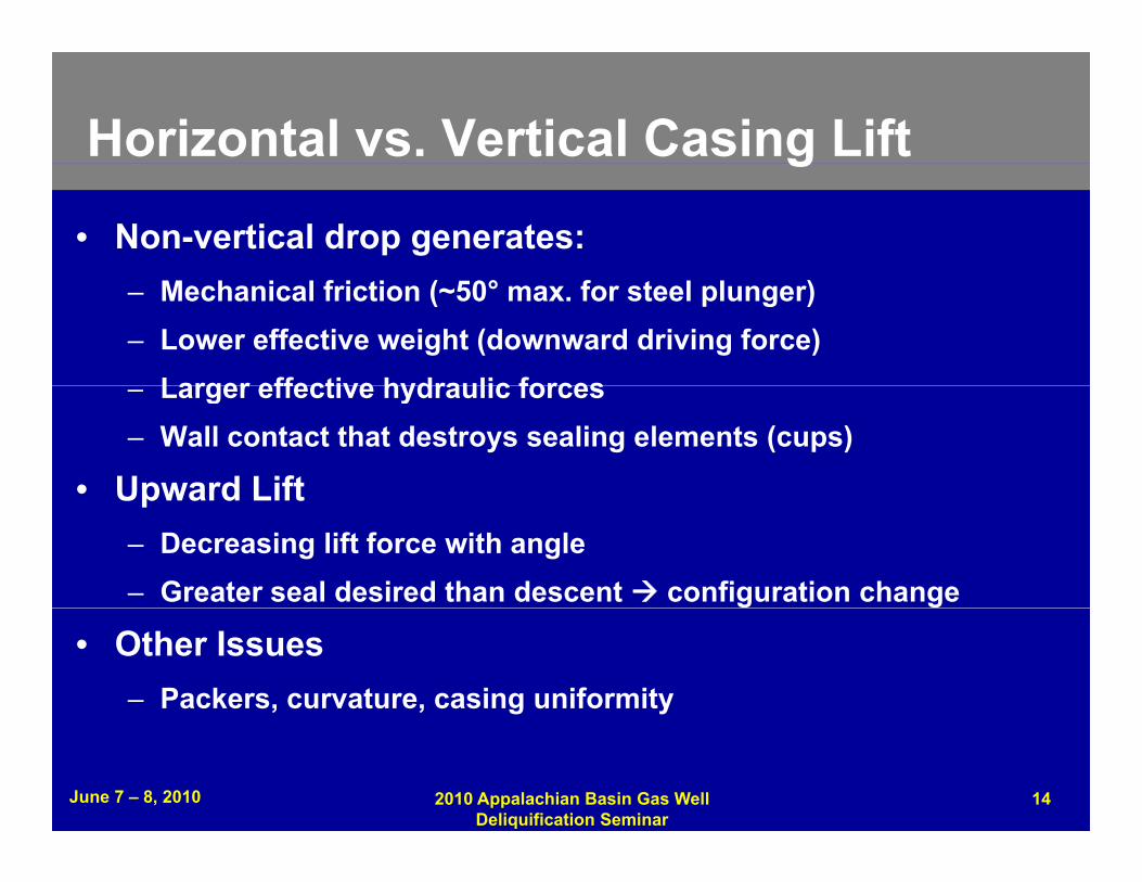
• Non-vertical drop generates:– Mechanical friction (~50° max. for steel plunger)– Lower effective weight (downward driving force)
Larger effective hydraulic forces– Larger effective hydraulic forces– Wall contact that destroys sealing elements (cups)
• Upward LiftUpward Lift– Decreasing lift force with angle– Greater seal desired than descent configuration change
• Other Issues– Packers, curvature, casing uniformity
June 7 – 8, 2010 142010 Appalachian Basin Gas Well Deliquification Seminar

Horizontal Well Constraints
• Force (gravity) available to move plunger decreases as it travels downholeit travels downhole– ½W @ 60°
• Force (pressure) required to lift fluid increases as• Force (pressure) required to lift fluid increases as plunger ascends
450
WEIGHT OF FLUID VS. ANGLE
200
250
300
350
400
bbl
brin
e (L
b) 4-½ x 11.6# CASING
0
50
100
150
200
Wei
ght o
f 1
June 7 – 8, 2010 152010 Appalachian Basin Gas Well Deliquification Seminar
0 10 20 30 40 50 60 70 80 90
Angle (from Vertical)
Horizontal Well Test Results
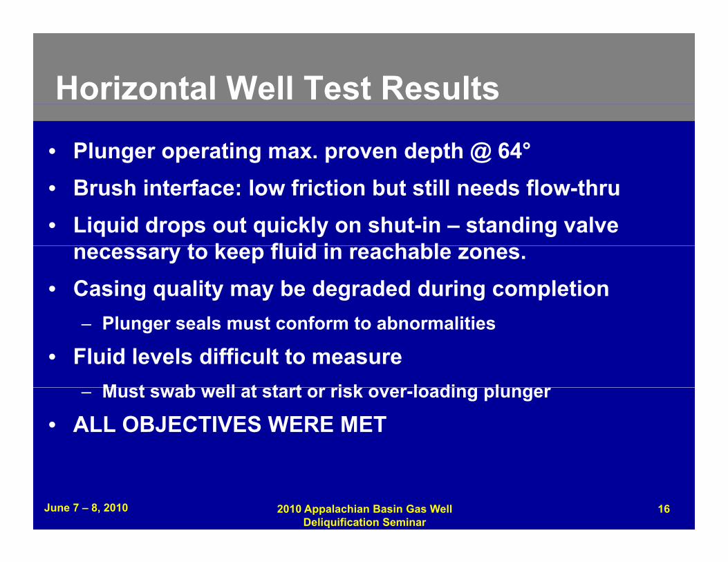
• Plunger operating max. proven depth @ 64°• Brush interface: low friction but still needs flow-thru• Liquid drops out quickly on shut-in – standing valve
t k fl id i h blnecessary to keep fluid in reachable zones.• Casing quality may be degraded during completion
Pl l t f t b liti– Plunger seals must conform to abnormalities
• Fluid levels difficult to measureM t b ll t t t i k l di l– Must swab well at start or risk over-loading plunger
• ALL OBJECTIVES WERE MET
June 7 – 8, 2010 162010 Appalachian Basin Gas Well Deliquification Seminar
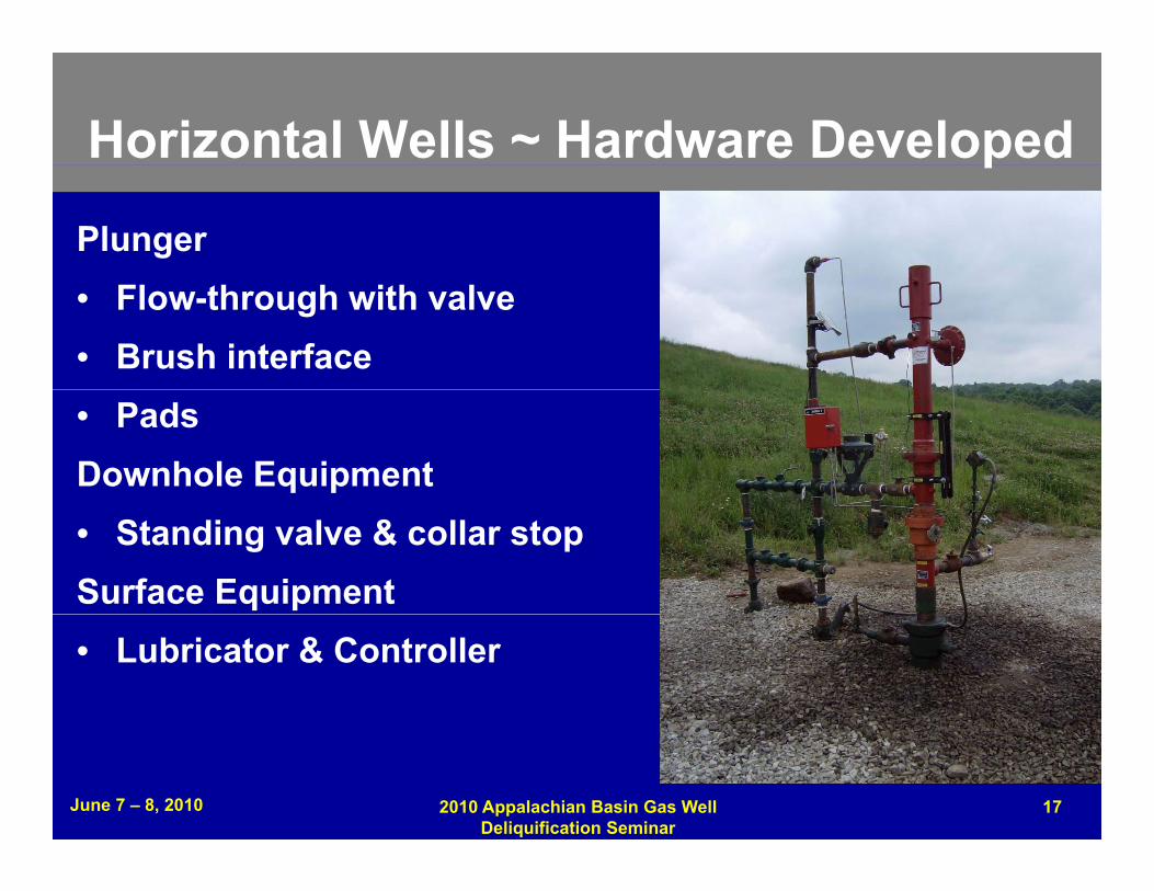
Horizontal Wells ~ Hardware Developed p
Plunger• Flow-through with valve• Brush interface• PadsDownhole Equipment• Standing valve & collar stopSurface Equipment• Lubricator & Controller
June 7 – 8, 2010 172010 Appalachian Basin Gas Well Deliquification Seminar

Horizontal Equipment Detailsq p• Brush-QT Plunger• Standing Valve• Standing Valve• Collar Stop
J t t ™ S f• Jetstar™ Surface Equipment
June 7 – 8, 2010 182010 Appalachian Basin Gas Well Deliquification Seminar

Case Histories
Vertical Wells• High-Pressure Wells @ 4-½" & 5- ½" in PA• New Well @ 4-½" in OH• Depleted Well @ 2-7/8" in TX• Depleted Wells @ 4-½" in MT & OKHorizontal Wells• Devonian Shale #1 @ 4-½" in KY• Devonian Shale #2 @ 4-½" in KY
June 7 – 8, 2010 192010 Appalachian Basin Gas Well Deliquification Seminar

Case #1~ Vertical Wells in Pennsylvania
12 i t ll ti J l 2009
y
• 12 installations, July 2009• Total Investment Payback = 47 days
$• Total Gas Sales Increase = $32,400/mo.• Assuming $5/MCF
June 7 – 8, 2010 202010 Appalachian Basin Gas Well Deliquification Seminar

Case #1~ Technical Summary
12 vertical wells with JetStar Casing PlungersS• Marcellus Shale
• Two are 5-½" x 17#, ten are 4-½" x 11.6#• PRock ~ 2,500psi & Psales > 50 psi• 6,000 to 10,000 ft. casing stand setting depth• 2 to 20 bbl/day brine water (frac. water flow-back)• All wells originally on pump-jack• Gas Flow prior to installation = 36.7 MCF/day (60d avg.)• Gas Flow after installation = 52.1 MCF/day
June 7 – 8, 2010 212010 Appalachian Basin Gas Well Deliquification Seminar
Average gas increase = 42%

Case #2 ~ New Vertical Well in Ohio
• Clinton Formation• 4-½" x 10.5#• PRock ~ 600psi after 24 hrs.• PSales > 60 psi, regulated by utility• 2 bbl/d oil, 10% water• 5 MCF/d avg. gas flow• Plunger runs 1 cycle/day• 6 hr shut-in & 45 min. open time, sold into utility lines• Casing Stand set just above perfs. @ 3,100 ft.
June 7 – 8, 2010 222010 Appalachian Basin Gas Well Deliquification Seminar
g j p @

Case #3 ~ Vertical Well in Texas• Permian Basin
Lower Canyon2-7/8" Casing Plunger Evaluation
• Lower Canyon Sands Play
• 2-7/8" x 6.4# 70
80113 day Average Production:Pre-Installation-- 7 mcfd
• PRock ~ 400psi• Psales > 100 psi
40
50
60tio
n M
CFDPre Installation 7 mcfdPost-Installation-- 13 mcfd
UN
GE
R
• 1 bbl/day water • ~2 cycles/day 20
30
40
aily
Pro
duct
PLU
y y• 6,560 ft.
0
10
-113 0 113
Da
June 7 – 8, 2010 232010 Appalachian Basin Gas Well Deliquification Seminar
-113 0 113Days on Production

Case #4~ Vertical Wells in OK & MT
• 4-½" x 10.5# Casing19 ll i Okl h• 19 wells in Oklahoma
• 7 – 8 bpd w/ 20 – 30% oil cut• 7300 – 7400 ft. setting depth• Gas flow taken from 20-30 MCF/d to 50-60 MCF/d
• 2 wells in Montana• 2 – 4 BPD of produced water• 2000 – 2050 ft. setting depth• 25-30 MCF/d increased to 85 – 90 MCF/d
June 7 – 8, 2010 242010 Appalachian Basin Gas Well Deliquification Seminar

Case #5~ Horizontal Well #1 in KY
• Devonian Shale• Brush-QT Plunger• 4-½" x 11.6#• 55° @ 3,675 ft.• PRock ~ 200 psi• Psales ~ 50 psi• Pure oil• < 5 bbl/week• Production up 50%
June 7 – 8, 2010 252010 Appalachian Basin Gas Well Deliquification Seminar

Case #6 ~ Horizontal Well #2 in KY• Brush-QT Plunger• Devonian Shale 100080 WATER• Devonian Shale• PRock ~ 300psi
P > 50 i 700
800
900
1000
60
70
80 WATERLINE_PRESGASInstall
Plunger
• Psales > 50 psi• 4-½" x 11.6#
° @ f500
600
700
40
50
MC
FD
/ PSI
G swab
• 44° @ 3,097 ft.• 2.5 bbl/d water
200
300
400
20
30
BPD
/ Plunger ran 3x
GAS FLOW
• 203% ↑ gas flow• Foam frac’d
0
100
0
10
/200
9
/200
9
/200
9
/200
9
/200
9
/200
9
/200
9
June 7 – 8, 2010 262010 Appalachian Basin Gas Well Deliquification Seminar
6/27
/
7/27
/
8/27
/
9/27
/
10/2
7/
11/2
7/
12/2
7/

Conclusions
• Casing plunger technology:I d ti b t ti ll• Increases production substantially
• Can be more economical than other options• Payback typically < 2 months
• In addition to extending life of older wells…• Has demonstrated safe application in
• High-pressure vertical wells• Horizontal wells to 64°
• Available for most casing sizes
June 7 – 8, 2010 272010 Appalachian Basin Gas Well Deliquification Seminar

Copyrightpy gRights to this presentation are owned by the company(ies) and/or author(s) listed on the title page. By submitting this presentation to ( ) p g y g pthe Gas Well Deliquification Workshop, they grant to the Workshop, the Artificial Lift Research and Development Council (ALRDC), and the Southwestern Petroleum Short Course (SWPSC), rights to:
– Display the presentation at the Workshop.– Place it on the www.alrdc.com web site, with access to the site to be
as directed by the Workshop Steering Committee.Pl i CD f di ib i d/ l di d b h– Place it on a CD for distribution and/or sale as directed by the Workshop Steering Committee.
Other use of this presentation is prohibited without the expressed written permission of the author(s) The owner company(ies) and/orwritten permission of the author(s). The owner company(ies) and/or author(s) may publish this material in other journals or magazines if they refer to the Gas Well Deliquification Workshop where it was first presented.
28June 7 – 8, 2010 2010 Appalachian Basin Gas Well Deliquification Seminar

DisclaimerThe following disclaimer shall be included as the last page of a Technical Presentation or Continuing Education Course. A similar disclaimer is included on the front page of the Gas Well Deliquification Web Site.The Artificial Lift Research and Development Council and its officers and trustees, and the Gas Well Deliquification Workshop Steering Committee members, and their supporting organizations and companies (here-in-after referred to as the Sponsoring Organizations), and the author(s) of this Technical Presentation or Continuing Education Training Course and their company(ies), provide this presentation and/or training material at the Gas Well Deliquification Workshop "as is" without any warranty of any kind, express or implied, as to the accuracy of the information or the products or services referred to by any presenter (in so far as such warranties may be excluded under any relevant law) and these members and their companies will not be liable for unlawful actions and any losses or damage that may result from use of any presentation as a consequence of any inaccuracies in, or any omission from, the information which therein may be contained.The views, opinions, and conclusions expressed in these presentations and/or training materials are those of the author and not necessarily those of the Sponsoring Organizations. The author is solely responsible for the content of the materials.The Sponsoring Organizations cannot and do not warrant the accuracy of these documents beyond the source documents, although we do make every attempt to work from authoritative y g ysources. The Sponsoring Organizations provide these presentations and/or training materials as a service. The Sponsoring Organizations make no representations or warranties, express or implied, with respect to the presentations and/or training materials, or any part thereof, including any warrantees of title, non-infringement of copyright or patent rights of others, merchantability, or fitness or suitability for any purpose.
29June 7 – 8, 2010 2010 Appalachian Basin Gas Well Deliquification Seminar