Choosing the Correct Balun - WestValleyARCwestvalleyarc.org/images/Antennas/Balun Selection By Dx...
22
Choosing the Correct Balun By Tom, W8JI General Info on Baluns Balun is an acronym for BALanced to UNbalanced, which describes certain circuit behavior in a transmission line, source or load. Most communications applications deal with two-terminal sources, transmission lines, and loads. This includes coaxial cables, open wire lines and systems working against earth or a ground plane as the”second conductor”. Press here for Balun Fundamentals and Terms The balun has to do a good job and be reliable. DX Engineering has the expertise to design and build a better balun that will deliver more power to the antenna, be more reliable, and in many cases cost less than products made by others. We also realized that advertising hype over the years had confused the issue of just what type of balun was appropriate to each antenna. This article is an attempt to define in simple terms how to get the most performance from your system, both on receiving and transmitting. The first thing to realize is that there are two types of baluns: Current Baluns and Voltage Baluns. Current baluns allow the output voltage, with respect to “ground” or outside world, to float to any value required to provide equal currents to each feedline conductor. In essence, current baluns are a universal device that could be used to drive either balanced or unbalanced lines equally well. Current baluns isolate the device connected at one end from the device connected at the other end, so the balanced terminals can be used to feed unbalanced or balanced loads equally well. They can also be used as broadband phase-invertors, baluns or un-uns. Voltage baluns always try to force the output terminals to equal voltages, which means currents can be far from even! A voltage balun almost certainly guarantees some feedline radiation (or reception), because there are very few “perfectly balanced” loads. We recommend current baluns, rather than voltage baluns, whenever possible. Current baluns provide better balance, often have lower loss and tolerate load impedance and balance variations much better than voltage baluns. Unless otherwise noted, DXE Baluns are current-type baluns.
Transcript of Choosing the Correct Balun - WestValleyARCwestvalleyarc.org/images/Antennas/Balun Selection By Dx...

Choosing the Correct Balun By Tom, W8JI General Info on Baluns Balun is an acronym for BALanced to UNbalanced, which describes certain circuit behavior in a transmission line, source or load. Most communications applications deal with two-terminal sources, transmission lines, and loads. This includes coaxial cables, open wire lines and systems working against earth or a ground plane as the”second conductor”. Press here for Balun Fundamentals and Terms The balun has to do a good job and be reliable. DX Engineering has the expertise to design and build a better balun that will deliver more power to the antenna, be more reliable, and in many cases cost less than products made by others. We also realized that advertising hype over the years had confused the issue of just what type of balun was appropriate to each antenna. This article is an attempt to define in simple terms how to get the most performance from your system, both on receiving and transmitting. The first thing to realize is that there are two types of baluns: Current Baluns and Voltage Baluns.
Current baluns allow the output voltage, with respect to “ground” or outside world, to float to any value required to provide equal currents to each feedline conductor. In essence, current baluns are a universal device that could be used to drive either balanced or unbalanced lines equally well. Current baluns isolate the device connected at one end from the device connected at the other end, so the balanced terminals can be used to feed unbalanced or balanced loads equally well. They can also be used as broadband phase-invertors, baluns or un-uns.
Voltage baluns always try to force the output terminals to equal voltages, which means currents can be far from even! A voltage balun almost certainly guarantees some feedline radiation (or reception), because there are very few “perfectly balanced” loads. We recommend current baluns, rather than voltage baluns, whenever possible. Current baluns provide better balance, often have lower loss and tolerate load impedance and balance variations much better than voltage baluns.
Unless otherwise noted, DXE Baluns are current-type baluns.

A Few Comments on Systems Requiring Antenna Tuners
Antenna systems requiring use of an antenna tuner for matching often have very high voltages or currents on the transmission lines and baluns, even at modest power. In some cases, coax is used to connect the tuner directly to the antenna. The feedline is connected to a coaxial connector on the tuner, and the tuner “matches” the poor SWR of the antenna system to the station equipment. The feedline beyond the tuner still has very high voltage, current and loss, even if the tuner input is matched to 50 ohms. In other cases, the antenna feedline is balanced, and the tuner has an internal or external balun. Unfortunately, most of the internal tuner baluns are 4:1 voltage baluns, which we will see is a poor choice. Less often, balanced tuners are used. Such tuners, while often better at power handling than the more common but less robust “T” network tuners, may still not provide the best transmission-line balance. They would have to be ground independent; otherwise, they are the resonant equivalent of a voltage balun.
There are four areas of concern in such systems:
1. In a multi-band system, the antenna almost never presents a uniform load to the balun. As the operating frequency changes, the balun load impedance can change from several thousand ohms to a few ohms.
2. Most antenna tuners work best into high impedances, rather than low impedances. Most baluns inside antenna tuners step the antenna impedance down. The tuner would actually work better if the balun simply passed the line impedance through without stepping it down.
3. 4:1 Baluns inside antenna tuners, which are usually voltage-type baluns, are very poor performers when presented with mismatched loads. 1:1 baluns are generally much more efficient and have a wider operating impedance range.
4. Voltage baluns have restricted frequency response. The “good performance” frequency range is much narrower in voltage baluns than in equivalent current-type baluns.
Based on the above facts, a 4:1 balun or any voltage-type balun is the wrong choice for use with antenna tuners in multi-band systems. Most tuners use them because they are cheap, easy to build, and because almost everyone else uses them.
Ron
Highlight
Ron
Highlight

Special DX Engineering Tuner Baluns For antenna tuners or systems with high SWR, we have a special balun. This balun uses high-voltage wire and has excellent performance at very high SWR. Even standard DXE baluns are better than many competing baluns, because many competing baluns use enameled wire for insulation. Our standard balun wire insulation doesn’t fail until voltage significantly exceeds 7500 volts, while most competing baluns that use enameled wire fail at less than 25% of that voltage! That means, for the same mismatched load impedance, our standard balun can handle sixteen times the power of enameled wire baluns! Our tuner balun has a breakdown voltage of over 15,000 Volts. Need we say more? Tuner baluns (denoted by “T” at the end of the balun part number) have slightly higher SWR when the load is perfectly matched, when no tuner is required. Because of that, we do NOT recommend T-suffix tuner baluns for higher frequencies (above 15 MHz) unless they are used with tuners. DXE tuner-baluns work equally well and handle the same power on the tuner input or output, so use them wherever most convenient for your system.
Resonant Dipoles A resonant dipole is cut for a particular band and its planned use is only within that band or on odd-harmonics where the SWR is naturally low. The well known formula for the length of the element is in feet is 468/F. The ultimate length may vary a few percent either shorter or longer so better to make it a little longer to start.
The best balun for this application is a 1:1 ratio current balun.
The part number of the correct balun would be the DXE-BAL050-H05-A or the DXE-BAL050-H10-A depending on power levels.
This antenna can use a coax feed and the balun is usually located right at the dipole element to ensure that the each side of the element receives equal currents and to keep currents off of the feedline. The feedline should then be led away from the antenna at right angles which will keep the antenna field from introducing current on the outside of the feedline after it leaves the balun and will keep the feedline from introducing noise onto the antenna element.
Here is an example of the balun setup that should be used with this antenna type.
The optional, formed plastic piece shown on the back of the DX Engineering balun allows it to be mounted on the wire element and removes the load of the balun and feedline from the element wire ends, which will keep them from breaking in most installations.

The top hole is used for support of the balun and feedline in the event that:
• The antenna will be used in the Inverted-V configuration.
• The balun hangs lower than desired.
• The stress on the wires is higher than usual due to wind or ice loading
The bracket can be used for the attachment of a “messenger line” that can be strung above the antenna wire. This line can be thin Dacron rope such as the STI-DBR-94-100 which has a breaking strength of 260 pounds. The use of the messenger line also will keep the antenna element from stretching over time which will change its resonant frequency.
The connection from the balun to shack would then be handled by coax. The best coax that you can afford is always the right choice.
Multi-band Dipoles
A Multi-band Dipole antenna is cut for a specific frequency, but plans call for it to be used on any of the frequencies above that.
This is a popular antenna and many have been built with DX Engineering baluns.
The correct construction technique is based on making the antenna element a half-wavelength on the lowest frequency on which the antenna will be used based on the 468/F formula.
The parallel conductor, air-dielectric feedline is led away from the antenna at right angles.
Lower impedance feedlines result in less extreme impedance changes from band-to-band. For instance, 600-ohm feedlines tend to present wider load impedance excursions to the tuner in multi-band applications than 300-ohm feedlines.
Yes, coax has still lower impedance, but the non-air dielectric causes great loss within the feedline with high SWR. For instance, at 10:1 SWR you lose half of your power for each 100 feet of coax. Parallel feedlines with air dielectric would have much less loss at the same SWR.
Ron
Highlight

Why you don't want to use coax when the SWR is high. For each 100 feet of coax, you lose half your power at an SWR of 10:1. At frequencies higher than 14MHz, it's worse. For higher loss coax like RG-58 or RG-8X it is worse, too. Plus, the SWR shown here is measured at the antenna, not at the radio where it would measure significantly lower but still would eat up just as much power.
Additional Info on Feedline Length with Multi-band Dipoles: Feedline length is critical to antenna performance. Always choose a feedline (connects the antenna to the balun, in this instance) that is 1/8th wavelength or some odd-multiple of 1/8th wavelength long on the lowest band. The table below shows the correct dimensions for the antenna and feedline for your Multi-band Dipole Antenna when using DX Engineering Ladder Line. Make the feedline any ODD multiple of the lengths shown. Make sure that you pick the correct column for 300-ohm or 450-ohm.
Make Feedline an ODD Multiple of This Length in Feet Lowest Frequency
on which the antenna will be used
(MHz)
Half-Wave Dipole (ft) Select Column Corresponding to Correct Velocity
Factor of Your Feedline. Velocity Factors Shown Are For DX Engineering Ladder Line
0.91 (450Ω ladder) 0.88 (300Ω ladder) 1.8 260 62.2 60.1 3.5 134 32.0 30.9 7 67 16.0 15.5
10.1 46 11.1 10.7 14 33 8.0 7.7 18 26 6.2 6.0 21 22 5.3 5.2
24.9 19 4.5 4.3 28 17 4.0 3.9
Table 1 - Length of Feedlines for Multi-band Dipoles
Ron
Highlight

The best balun for this application is a 1:1 ratio current balun.
A 1:1 balun has the widest operating frequency range, lowest core stress, and provides the best overall balance of any balun for given cost, size, and weight.
The part number of the correct balun would be the DXE-BAL050-H10-AT or the DXE-BAL050-H11-CT depending on power levels and operating environment.
Often, a 4:1 balun is suggested for Multi-band Dipoles; however, the best balun to use for this application is a 1:1 ratio. The impedance at the end of the feedline is going to vary greatly from very high to very low. Tuners have an easier time with high impedance than a low one. A balun with a ratio of 4:1 or more will transform already low impedance to an even lower one that will make the antenna hard to tune. The 1:1 ratio balun will just pass the low impedance through.
The parallel conductor feedline should be constructed according to the chart above and lead to the balun located at a convenient location. The balun should be located such that the coax between it and the tuner is as short as possible BUT do not route the parallel line so close to the tuner or the rest of the station equipment that RF feedback occurs. This will manifest itself by making the tuning of the antenna very difficult and the controls will be very “touchy”. There may also be RF present on the microphone, key, etc.
Even when properly done, this arrangement will subject the coaxial line between the tuner and balun to very high standing waves and high voltage and/or current. You should use good low-loss coaxial line and keep the coaxial line length as short as possible, RG8X and smaller will not do a proper job. Belden RG-213 or equivalent is the minimum. DX Engineering baluns have significantly higher common-mode impedance and larger effective core area than other similar designs. They are much more effective antenna tuner baluns than standard bead or air-core baluns.
Ron
Highlight

Conventional or True Windom Antennas The True or Conventional Windom antenna, shown below, is fed with a single-wire line, and fed as an unbalanced system against a reasonable RF ground or counterpoise. The feed is similar to a long-wire antenna, except the horizontal wire is fed with a few percent offset from the center.
Single-wire Windom Feed.
Red “D” in DX indicates same phase (positive phase) output terminal on that side.
When you use a single wire feed, ground the unused balanced terminal to the counterpoise or radial system. DO NOT connect that system to the station ground. Isolating the station ground from the antenna ground will keep unwanted RF off station equipment, and reduce potential problems with unwanted RF in the house.

Balanced Feed Windom Antennas (Off-Center Fed Dipoles) Another, more popular version of a Windom antenna, shown below, is fed with open wire or ladder line. It is sometimes called a “balanced feed” Windom, even though it is actually an “Off-Center Fed” dipole.
Properly installed Windom antennas have impedances in the 400-600 ohm range at resonant frequencies. Depending on the installation, a Windom antenna may have reasonable impedances at several harmonically related frequencies. The best balun for both antennas, assuming they operated where standing waves on the feed system are low, are 9:1 baluns.
Unless otherwise labeled, DX Engineering 9:1 ratio baluns have the advantage of being current baluns. Current baluns, as mentioned earlier, can be used to feed unbalanced loads or balanced loads.
When using a balanced feed system the length of the feedline is the same as shown in the table for the Multi-band Dipoles above, an odd-eighth-wave depending on the lowest frequency used.
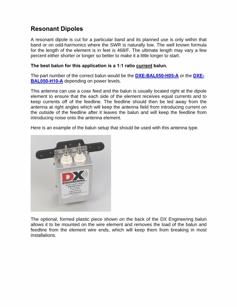
The best balun for the Windom or Off-Center Fed Dipole is a 9:1 ratio current balun.
The part number of the correct balun would be the DXE-BAL450-H10-A.
Off-Center fed antennas are much more sensitive to their surroundings than a balanced antenna such as a dipole. Things that affect them would be buildings, other antennas, any metallic object, their height above ground and ground conductivity. Half-Wave Vertical Antennas
Some antennas that are end-fed or asymmetrically fed can generate current on the feedline even though the balun has low SWR. Examples would be a “dipole” or vertical, either symmetrically or asymmetrically constructed, where the feed cable leaves the antenna near a high voltage point. This can be because of a small counterpoise, because the coax itself is the counterpoise, or because the feedline is routed along the antenna. Commercial examples of this are Gap, MFJ, HyGain, and Cushcraft “no radial” verticals, as well as Force 12 vertical dipoles. In these cases, a DX Engineering Feedline Current Choke (part number DXE- FCC050-H05-A) placed five to twenty-five feet away from the antenna will greatly reduce feedline currents.
One manufacturer of log-periodic antennas suggests running the feedline along a boom that is “hot” with RF, which means the shield of the coax is coupled directly to one conductor of a “hot” transmission line! In this case, a Feedline Current Choke should be placed at the point where the feedline leaves the antenna boom, but before it reaches the tower.
http://www.dxengineering.com/Parts.asp?ID=60&PLID=50&SecID=10&DeptID=9&PartNo=DXE%2DBAL450%2DH10%2DA
Ron
Highlight
Ron
Highlight

Feedline Current Choke: Use with any vertical or horizontal antenna that is coaxially fed. Examples where this may be necessary are in small dipole antennas such as Force 12 vertical dipoles when the feedline does not leave the antenna at right angles, shortened or loaded antennas using the coax as a counterpoise, verticals with very small or shortened radial systems, full-size dipoles using the feedline shield as the “other leg” of a dipole, so-called ‘end-fed’ dipoles which use the feedline as the other half of the antenna and even regular dipoles if the feedline parallels the antenna element for any appreciable distance. In all of these cases, a Feedline Current Choke (FCC050-H05-A) will greatly reduce unwanted or harmful feedline radiation or reception. The FCC-050 should be installed several feet away from the antenna. In all cases, it must be installed before the feedline is routed against other cables, a metallic mast or a tower.
What are the benefits of using a Feedline Current Choke? All of the above antenna examples usually have very high common-mode feedline currents which often lead to:
• RFI problems, either with the amateur equipment or consumer devices
• Noise picked up by the feedline being conducted to the antenna
• Signals picked up by the feedline decreasing the directivity of the antenna system, especially the front-to-back ratio.
While most common advice is to improve the station’s RF ground, the root of the problem is in the poor isolation of the feedline from antenna currents. If you wish to reduce feedline radiation and improve reception, a Feedline Current Choke is required. In these examples, if SWR is already low, adding a DX Engineering Feedline Current Choke at the point where the feedline exits the area of the antenna will substantially reduce unwanted feedline radiation or reception without the need for improved station grounding.
Ron
Highlight
Ron
Highlight
Ron
Highlight

Quarter-Wave Vertical Antennas When Quarter-wave antennas are constructed over a good radial system, they have a feedpoint impedance of about 36 ohms. When they are constructed over less than a good radial-system there is a loss introduced into the feed system that adds to the 36-ohm figure. This improves the SWR but there is a loss in the efficiency of the antenna, signals transmitted and received have a higher take-off angle and often there is current introduced on to the feedline. When the vertical uses elevated radials, it is difficult to keep current from traveling back to the operating position via the feedline unless a Feedline Current Choke is used.
With a ground-mounted quarter-wave vertical, regardless of the radial situation, but especially with poor radial systems, there is the need for a feedline choke or balun system to keep current off the feedline.
The correct location for such a system is at the base of the vertical portion of the antenna.
For raised quarter-wave verticals with elevated radials, the correct item to use is the Feedline Current Choke. This should be positioned UNDER the radials at the feedpoint of the raised vertical.
The Feedline Current Choke part number would be DXE-FCC050-H05-A.
For ground mounted quarter-wave verticals, the best balun for this application is a 1:1 ratio current balun.
The part number of the correct balun would be the DXE-VFCC-H05-A or the higher power DXE-VFCC-H10-A.
Below is a picture of the DX Engineering Insulated Balun Mount when used with the Hustler BTV family of vertical antennas. Notice that the balun housing is insulated from the radial system.
Ron
Highlight
Ron
Highlight
Ron
Highlight

Figure 1 Insulated Balun System for use with Hustler Antenna and Radial Plate. The braid is sized for use with the Tilt-Base and Radial Plate.
Figure 2 Insulated Balun System for Use with Hustler Antenna without Radials. Even though this is not recommended, we realize that many people do it anyway, so this is a way to reduce the resulting current on the feedline. When installing a Hustler antenna the best way to do it is with a Radial Plate and a minimum of 16 radials that are ¼-wavelength at the lowest frequency anticipated. The DX Engineering Insulated Balun System is meant to attach to the antenna support post, the antenna feedpoint and directly to the Radial Plate. For various reasons, people sometimes install the Hustler antennas with no radials or with an inadequate number of radials. This is not recommended, but it happens. As a result, the antenna uses the coax as a radial and by doing so, introduces current to the braid of the feedline, which can travel to the operating position with the results mentioned above. In order to reduce the current on the feedline in these situations it is still possible to use the DX Engineering Insulated Balun System. In this case, attach the terminal that would normally go to the Radial Plate to the frame of the antenna support as shown in the above picture. The use of an 8-inch piece of 450-ohm twin-lead is a convenient medium for doing so.

Sometimes, as the coax feedline travels through the near-field of the antenna, the current can be re-introduced to the feedline after the balun. In that case, a Feedline Current Choke should be inserted into the feedline after it exits the near-field of the antenna. Loop Antennas – Horizontal and Vertical Closed-loop antennas have moderately low impedances if they are about 1 wavelength in circumference. They present low feedpoint impedances at all multiples or harmonics of the initial resonant frequency as opposed to dipole antennas that have low feedpoint impedances only at ODD multiples of the initial resonant frequency. There are three common operating conditions for a loop antenna: 1 - Operation near fundamental resonance - A Single Band Loop: When a Horizontal Full-Wave Loop is operated near resonance on the full-wavelength band a 4:1 balun works very well. Using good-quality 50-ohm coaxial cable to the shack from the balun, SWR at resonance will normally be below 1.5:1. An external antenna tuner will generally not be required; the radio’s internal tuner can be used if needed.
Typical SWR Plot of full-wave horizontal loop at approximately 60 feet above average ground using DX Engineering 4:1 balun. Operation is safe for balun and coaxial feedline over the entire band.
Ron
Highlight

Horizontal Full-Wave Loop: The best balun for operation at resonance is a 4:1 ratio current balun.
The part number of the correct balun would be the DXE-BAL200-H05-A or the DXE-BAL200-H10-A depending on power levels.
Vertical Full-Wave Loop: The best balun for operation at resonance is a 2:1 ratio current balun.
The part number of the correct balun would be the DXE-BAL100-H10-A or the DXE-BAL100-H11-A or the DXE-BAL100-H11-C depending on power levels and operating environment.
2 - Operation moderately far from resonance or on harmonics: When operating a Vertical or Horizontal Loop moderately far from resonance or on harmonics, average SWR will be lowest using a 4:1 balun. An example of this is operating a loop cut for 3.7MHz near the bottom or top of the band, or using a 3.6MHz loop on 7.2MHz. When operating moderately close (within 200 kHz) of resonance, losses will be reasonable. Good quality coaxial cable should be installed between the balun and the loop. An external tuner can be used at the operating position, be sure SWR without the tuner is under 5:1.
http://www.dxengineering.com/Parts.asp?ID=29&PLID=50&SecID=10&DeptID=9&PartNo=DXE%2DBAL200%2DH05%2DA
http://www.dxengineering.com/Parts.asp?ID=43&PLID=50&SecID=10&DeptID=9&PartNo=DXE%2DBAL200%2DH10%2DA

Above is an SWR Plot of full-wave horizontal loop at 60 feet, resonant at 3.54MHz while using a DX Engineering 4:1 balun. Below is 40 meter SWR.
The plots above show with a DX Engineering 4:1 balun and reasonably good coax, you can operate a loop over most of 80 and all of 40 meters. This system is generally good on 80, 40, 20, 15 and 12 meters.

Vertical or Horizontal Loop: The best balun for operation moderately far from resonance or on harmonics is a 4:1 ratio current Tuner Balun.
The part number of the correct balun would be the DXE-BAL200-H10-AT or the DXE-BAL200-H11-CT depending on power levels and operating environment.
3 - Operation far from resonance: When operating the loop on random unplanned frequencies far from resonance, use the balanced feedline with the lowest impedance and loss available (300-ohm transmitting twin lead is best). Place the balun as close to the tuner as possible. Use a 1:1 Tuner Balun. Avoid using coax in any part of the system with high SWR (over 5:1).
Vertical or Horizontal Loop: The best balun for operation far from resonance is a 1:1 ratio current Tuner Balun.
A 1:1 balun has the widest operating frequency range, lowest core stress, and provides the best overall balance of any balun for given cost, size, and weight.
The part number of the correct balun would be the DXE-BAL050-H10-AT or the DXE-BAL050-H11-CT depending on power levels and operating environment.

Some Notes on Feedline Length When Using a Loop Far From Resonance: Feedline length is critical to antenna performance. Try to choose a feedline that is a multiple of 1/2 wavelength long on the lowest band, and make the loop antenna for the lowest band on which you will operate.
Make Feedline an ODD Multiple of This Length in Feet (x 1, 3, 5, etc.) Lowest Frequency
on which the antenna will be used
(MHz)
Full-Wave Loop (ft)
1005/f Select Column Corresponding to Correct Velocity
Factor of Your Feedline. Velocity Factors Shown Are For DX Engineering Ladder Line
0.91 (450Ω ladder) 0.88 (300Ω ladder) 1.8 558 248.6 240.4 3.5 287 127.9 123.7 7 144 63.9 61.8
10.1 100 44.3 42.8 14 72 32.0 30.9 18 56 24.9 24.0 21 48 21.3 20.6
24.9 40 18.0 17.4 28 36 16.0 15.5
Table 1 - Length of Feedlines for Multi-band Full-Wave Loops

Long-Wire Antennas Long wire antennas are typically horizontal antennas, fed at one end and are at least ½-wavelength long at the frequency at which they will be operated. The impedance of a long wire antenna varies as the frequency is changed but the normally accepted values are about 200 to 450-ohms depending on length, height, ground conditions and frequency. The only way to know the impedance is to measure it or at least model it with antenna software. That being said, a 4:1 balun using good coax leading to an antenna tuner will provide a relatively well behaved installation. The output terminal closest to the red “D” in the DX Engineering label should be connected to the wire. The other terminal can be connected to the antenna ground which ideally would be a system of radials or at the very least, one radial lying on the ground or buried. The length of the radial should be a ¼-wave on the lowest frequency planned. The case of the balun should be attached to a separate ground rod.
Long-wire Feed using a 4:1 Balun. The antenna ground side should be attached to a radial system as with a vertical antenna. Like any other antenna system that involves high SWR, it will behoove the builder to use the shortest length and best quality coax possible.

Longwire Antenna: The suggested balun is a 4:1 ratio current Tuner Balun.
The part number of the correct balun would be the DXE-BAL200-H10-AT or the DXE-BAL200-H11-CT depending on power levels and operating environment.

Log Periodic, Rhombic, V Beam and Other Broadband Antennas Some antennas have very little impedance change with frequency. Log Periodic, Terminated Inverted V’s, Terminated V-beam antennas and Terminated Rhombic antennas are examples of antennas that are very stable with impedance over very wide frequency ranges. Select a balun closest to the antenna feedpoint impedance (you’ll have to get this from textbooks or modeling), and use it at the feedpoint or where the feedline from the antenna ends. Be sure the feedline between the balun and antenna feedpoint matches the antenna impedance as closely as possible.
Tennadyne Log Periodic Antennas Keep the feed from the antenna as short as possible. The balun should be used before the feedline comes close to any metal or is secured to a tower or mast
Traditional* Log Periodic, Rhombic, V Beam and Other Broadband Antennas * All elements insulated from boom.

An Explanation of Our Ratings SWR When they are terminated in the designed output impedance, DX Engineering baluns have lower SWR over much wider frequency ranges than competing baluns. Typical SWR curves of DX Engineering 1:1 and 4:1 baluns remain well under 1.3:1 even beyond the stated range of operation. Even our least expensive baluns have lower SWR over much wider frequency ranges than other baluns. The extremely wide frequency range where SWR is low shows how we carefully select materials, layout and the construction process. Power Rating DX Engineering baluns are conservatively rated. Materials are selected to provide substantial headroom. Baluns are tested to work beyond specified worst case conditions. We specify the power rating at 3:1 SWR. Balance DX Engineering baluns, unless specified otherwise, are current baluns. Current baluns try to force equal and opposite currents, regardless of load balance conditions. Equal currents mean minimum radiation near the balun. High common-mode impedance is a very desirable trait in most baluns, since high common-mode impedance assures the best balance under widely varying load conditions. DX Engineering baluns have significantly higher common-mode impedance than popular competing baluns, often being several times better. More important, DX Engineering baluns maintain the high impedance over wider frequency ranges. Our baluns do a better job of reducing feedline radiation and RF-in-the-shack. Loss DX Engineering baluns have such low loss they handle very high power without heating. Losses in our baluns, when properly terminated, are nearly immeasurable on typical equipment like power meters. Even greatly mismatched, our baluns’ losses remain lower than competing baluns. The extra power goes to your antenna, rather than overheating and possibly damaging the balun. ver 3.7.08