Choice of steel material for bridge bearings to avoid...
136
Report EUR 25390 EN 2012 M. Feldmann, B. Eichler, G. Sedlacek, W. Dahl, P. Langenberg, C. Butz, H. Leendertz, G. Hanswille Editors: A. Pinto, A. Athanasopoulou and H. Amorim-Varum Background documents in support to the implementation, harmonization and further development of the Eurocodes Choice of steel material for bridge bearings to avoid brittle fracture
Transcript of Choice of steel material for bridge bearings to avoid...

Report EUR 25390 EN
2 0 1 2
M. Feldmann, B. Eichler, G. Sedlacek, W. Dahl, P. Langenberg, C. Butz, H. Leendertz, G. Hanswille Editors: A. Pinto, A. Athanasopoulou and H. Amorim-Varum
Background documents in support to the implementation, harmonization and further development of the Eurocodes
Choice of steel material for bridge bearings to avoid brittle fracture
European Commission Joint Research Centre
Institute for the Protection and Security of the Citizen
Contact information Artur Pinto
Address: Joint Research Centre, Via Enrico Fermi 2749, TP 480, 21027 Ispra (VA), Italy
E-mail: [email protected]
Tel.: +39 0332 78 9294
Fax: +39 0332 78 9049
http://ipsc.jrc.ec.europa.eu/
http://www.jrc.ec.europa.eu/
Legal Notice Neither the European Commission nor any person acting on behalf of the Commission
is responsible for the use which might be made of this publication.
Europe Direct is a service to help you find answers to your questions about the European Union
Freephone number (*): 00 800 6 7 8 9 10 11
(*) Certain mobile telephone operators do not allow access to 00 800 numbers or these calls may be billed.
A great deal of additional information on the European Union is available on the Internet.
It can be accessed through the Europa server http://europa.eu/.
JRC72676
EUR 25390 EN
ISBN 978-92-79-25439-0
ISSN 1831-9424
doi:10.2788/33897
Luxembourg: Publications Office of the European Union, 2012
© European Union, 2012
Reproduction is authorised provided the source is acknowledged.
Printed in Italy
Choice of steel material for bridge bearings to avoid
brittle fracture
M. Feldmann, B. Eichler, G. Sedlacek, W. Dahl, P. Langenberg, C. Butz, H. Leendertz, G. Hanswille
Background documents in support to the implementation, harmonization and further development of the Eurocodes
Joint Report
Prepared in cooperation of experts from CEN / TC 250, CEN / TC 167 and from metallurgy
Editors: A. Pinto, A. Athanasopoulou and H. Amorim-Varum

The European Convention for Constructional Steelwork (ECCS) is the federation of the National Associations of Steelwork industries and covers a worldwide network of Industrial Companies, Universities and Research Institutes. http://www.steelconstruct.com/ Contact information Address: Mies-van-der-Rohe-Straße 1, D-52074 Aachen E-mail: [email protected] Tel.: +49 241 80 25177 Fax: +49 241 80 22140 http://www.stb.rwth-aachen.de

In the memory of Professor Dr.-Ing. Gerhard Sedlacek; With his high scientific and technical skills, Professor Sedlacek he has been a guide and an example to all of us. He was an innovator, a bright and young-minded person. Professor Sedlacek was a real European in spirit and action and his work for the Eurocodes has left a lasting legacy. He has given full support to the Joint Research Centre for the activities concerning the implementation, harmonization and further development of the Eurocodes and he has enthusiastically defended the involvement of the JRC in the Eurocodes activities from the very beginning. Professor Sedlacek will always be remembered.
Joint Research Centre – Eurocodes Team


Foreword
The construction sector is of strategic importance to the EU as it delivers the buildings and infrastructure needed by the rest of the economy and society. It represents more than 10% of EU GDP and more than 50% of fixed capital formation. It is the largest single economic activity and the biggest industrial employer in Europe. The sector employs directly almost 20 million people. In addition, construction is a key element for the implementation of the Single Market and other construction relevant EU Policies, e.g.: Environment and Energy.
In line with the EU’s strategy for smart, sustainable and inclusive growth (EU2020), Standardization will play an important part in supporting the strategy. The EN Eurocodes are a set of European standards which provide common rules for the design of construction works, to check their strength and stability against live and extreme loads such as earthquakes and fire.
With the publication of all the 58 Eurocodes parts in 2007, the implementation of the Eurocodes is extending to all European countries and there are firm steps towards their adoption internationally. The Commission Recommendation of 11 December 2003 stresses the importance of training in the use of the Eurocodes, especially in engineering schools and as part of continuous professional development courses for engineers and technicians, noting that they should be promoted both at national and international level.
In light of the Recommendation, DG JRC is collaborating with DG ENTR and CEN/TC250 “Structural Eurocodes” and is publishing the Report Series ‘Support to the implementation, harmonization and further development of the Eurocodes’ as JRC Scientific and Technical Reports. This Report Series include, at present, the following types of reports:
1. Policy support documents – Resulting from the work of the JRC and cooperation with partners and stakeholders on ‘Support to the implementation, promotion and further development of the Eurocodes and other standards for the building sector.
2. Technical documents – Facilitating the implementation and use of the Eurocodes and containing information and practical examples (Worked Examples) on the use of the Eurocodes and covering the design of structures or their parts (e.g. the technical reports containing the practical examples presented in the workshops on the Eurocodes with worked examples organized by the JRC).
3. Pre-normative documents – Resulting from the works of the CEN/TC250 Working Groups and containing background information and/or first draft of proposed normative parts. These documents can be then converted to CEN technical specifications.
4. Background documents – Providing approved background information on current Eurocode part. The publication of the document is at the request of the relevant CEN/TC250 Sub-Committee.
5. Scientific/Technical information documents – Containing additional, non-contradictory information on current Eurocodes parts which may facilitate implementation and use, preliminary results from pre-normative work and other studies, which may be used in future revisions and further development of the standards. The authors are various stakeholders involved in Eurocodes process and the publication of these documents is authorized by the relevant CEN/TC250 Sub-Committee or Working Group.
Editorial work for this Report Series is assured by the JRC together with partners and stakeholders, when appropriate. The publication of the reports type 3, 4 and 5 is made after approval for publication from the CEN/TC250 Co-ordination Group.

The publication of these reports by the JRC serves the purpose of implementation, further harmonization and development of the Eurocodes, However, it is noted that neither the Commission nor CEN are obliged to follow or endorse any recommendation or result included in these reports in the European legislation or standardization processes.
This report is part of the so-called Scientific/Technical information documents (Type 5 above). It is a joint JRC-ECCS report and it part of a series of documents in support to the implementation and further evolution of Eurocode 3.
The editors and authors have sought to present useful and consistent information in this report. However, users of information contained in this report must satisfy themselves of its suitability for the purpose for which they intend to use it.
The report is available to download from the “Eurocodes: Building the future” website (http://eurocodes.jrc.ec.europa.eu). Ispra, June 2012
Artur Pinto and Adamantia Athanasopoulou
European Laboratory for Structural Assessment (ELSA)
Institute for the Protection and Security of the Citizen (IPSC)
Joint Research Centre (JRC) – European Commission
Humberto Amorim-Varum
Departamento de Engenharia Civil
Universidade de Aveiro
(Former Seconded National Expert at the Joint Research Centre)

Acknowledgement
(1) This JRC-Scientific and Technical Report has been prepared in cooperation with the producers of transition joints and bearings for civil engineering works, in particular with the member companies of VHFL, that also sponsored the works.
(2) The draft has been discussed with experts from WG8 of CEN/TC 167, from CEN/TC 250 and other invited experts to achieve consistency across different fields of application of steel. The works of Dr. B. Kühn and Dr. M. Lukic from ECCS-TC6 have been most valuable.
(3) The financial support of the works and the valuable contributions from the cooperation and discussion are gratefully acknowledged.
(4) Particular thanks are to the Joint Research Centre for the editorial works.
Aachen, March 2011 Prof. Dr.-Ing. G. Sedlacek Director of ECCS-Research

i
Introduction
(1) This JRC-Scientific and Technical Report deals with the choice of steel material for the production of bearings to avoid brittle fracture of the steel components of these bearings under low temperature conditions.
(2) This report has been initiated by the “VHFL-Vereinigung der Hersteller von Fahrbahnübergangen und Lagern für Bauwerke “ (Association of producers of transition joints and bearings for civil engineering works).
(3) The objective was to prepare a tool on the basis of the procedure in EN 1993-1-10 – Choice of material to avoid brittle fracture - for normal steel fabrication, that allows to select the suitable steels for the various components of bearings such, that the regulatory requirements for safety under low temperatures are met.
(4) As this JRC-Report is connected with the product standards for bearings, in particular EN 1337, it has been prepared in cooperation of experts from CEN/TC 250, CEN/TC 167 and invited metallurgists.
(5) The purpose of the JRC-Report is to serve as an information and guidance and also to be used for the further development of EN 1337 and EN 1993.

iii
Executive summary
(1) Due to a significant decrease of toughness properties of structural steel with decreasing temperatures there is a risk that structural steel components may under low temperatures be susceptible to brittle fracture.
(2) EN 1993-1-10 provides a method to avoid such brittle fracture by an appropriate choice of steel grade.
(3) The background of this method is a fracture mechanics safety assessment for a particular accidental scenario that includes extremely low temperatures, the presence of crack-like flaws at critical Hot-Spots, that have grown by fatigue
effects, the presence of nominal stresses Ed, and of material properties as specified in EN 10025.
(4) The purpose of this report is to adapt the method in EN 1993-1-10 used for normal steel structures to the specific case of steel components of structural bearings that are produced according to EN 1337 and are subject to specific design, fabrication and installation methods.
(5) In this adaptation the specific shapes of components generally machined from plates and the particular loading and verification models for the design of the components have been taken into account, so that eventually selection tables as in EN 1993-1-10 could be established.
(6) In case a Finite-Element analysis is applied in the design of the components of
bearings the appropriate method to determine the reference stress Ed is a Hot-
Spot-stress HS as defined by Dong.
(7) For usual dimensions of bearings a simplified procedure is offered that refers to
nominal values of bend,d as the surface stress from the linear bending theory.
(8) A worked example illustrates the use of the simplified procedure.
Ispra, September 2011
J.A. Calgaro, U. Kuhlmann, G. Sedlacek, CEN/TC250
H. Leendertz, CEN/TC 167
A. Pinto, JRC

v
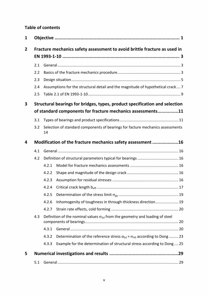
Table of contents
1 Objective ................................................................................................ 1
2 Fracture mechanics safety assessment to avoid brittle fracture as used in
EN 1993-1-10 .......................................................................................... 3
2.1 General ..................................................................................................................... 3
2.2 Basics of the fracture mechanics procedure ............................................................ 3
2.3 Design situation ........................................................................................................ 5
2.4 Assumptions for the structural detail and the magnitude of hypothetical crack .... 7
2.5 Table 2.1 of EN 1993-1-10 ........................................................................................ 9
3 Structural bearings for bridges, types, product specification and selection
of standard components for fracture mechanics assessments................ 11
3.1 Types of bearings and product specifications ........................................................ 11
3.2 Selection of standard components of bearings for facture mechanics assessments 14
4 Modification of the fracture mechanics safety assessment .................... 16
4.1 General ................................................................................................................... 16
4.2 Definition of structural parameters typical for bearings ....................................... 16
4.2.1 Model for fracture mechanics assessments .............................................. 16
4.2.2 Shape and magnitude of the design crack ................................................. 16
4.2.3 Assumption for residual stresses ............................................................... 16
4.2.4 Critical crack length beff .............................................................................. 17
4.2.5 Determination of the stress limit gy ......................................................... 19
4.2.6 Inhomogenity of toughness in through-thickness direction ...................... 19
4.2.7 Strain rate effects, cold forming ................................................................ 20
4.3 Definition of the nominal values Ed from the geometry and loading of steel components of bearings ......................................................................................... 20
4.3.1 General ....................................................................................................... 20
4.3.2 Determination of the reference stress σEd = HS according to Dong ......... 23
4.3.3 Example for the determination of structural stress according to Dong .... 25
5 Numerical investigations and results ..................................................... 29
5.1 General ................................................................................................................... 29

vi
5.2 Component No 1 – Rotationally-symmetric top component, type A (sliding plate and lateral guiderail) .............................................................................................. 31
5.2.1 Geometry, load assumptions and boundary conditions ............................ 31
5.2.2 Hot-Spot-stresses ....................................................................................... 32
5.2.3 Stress intensity factors ............................................................................... 33
5.2.4 Assessments to avoid brittle fracture ........................................................ 34
5.3 Component No. 2A – Axisymmetric top component (sliding plate and guiderail) 38
5.3.1 Geometry, load and assumption and boundary condition ........................ 38
5.3.2 Hot-Spot-stresses ....................................................................................... 38
5.3.3 Stress intensity factors ............................................................................... 38
5.3.4 Assessments to avoid brittle fracture ........................................................ 41
5.4 Component No. 2B – Axisymmetric top component of reference bearing type B (welded variant) ..................................................................................................... 44
5.4.1 Geometry, load assumptions and boundary conditions ............................ 44
5.4.2 Hot-Spots-stresses ...................................................................................... 47
5.4.3 Stress intensity factors ............................................................................... 49
5.4.4 Assessments to avoid brittle fracture ........................................................ 55
5.5 Component No. 3 – Axisymmetric bottom component of bearing ....................... 64
5.5.1 Geometry, load assumptions and boundary conditions ............................ 64
5.5.2 Hot-Spot stresses ....................................................................................... 65
5.5.3 Stress-intensity factors ............................................................................... 66
5.5.4 Assessments to avoid brittle fracture ........................................................ 67
5.6 Component No. 4 – Axisymmetric anchor plate .................................................... 72
5.6.1 Geometry, load assumptions and boundary conditions ............................ 72
5.6.2 Hot-Spot-stresses ....................................................................................... 72
5.6.3 Stress intensity factors ............................................................................... 73
5.6.4 Assessments to avoid brittle fracture ........................................................ 73
5.7 Component No. 5 – Bearing for horizontal forces without rotation and capacity for vertical forces ................................................................................................... 75
5.7.1 Geometry, load assumptions and boundary conditions ............................ 75
5.7.2 Hot-Spot-stresses ....................................................................................... 76
5.7.3 Stress intensity factors ............................................................................... 77
5.7.4 Assessments to avoid brittle fracture ........................................................ 78
6 Proposal for a standard procedure for the assessment to avoid brittle
fracture when using FE-calculations ....................................................... 84

vii
7 Worked example for the assessment to avoid brittle fracture using FE-
calculations ............................................................................................ 88
7.1 General ................................................................................................................... 88
7.2 Determination of the Hot-Spot-stresses ................................................................ 89
7.3 Assessment ............................................................................................................. 90
8 Simplified assessment with reference to ultimate limit state verifications
.............................................................................................................. 92
8.1 General ................................................................................................................... 92
8.2 Correlations ............................................................................................................ 92
8.3 Consequences for the choice of material to avoid brittle fracture ....................... 93
9 Worked examples .................................................................................. 95
9.1 General ................................................................................................................... 95
9.2 Design situation ...................................................................................................... 95
9.3 Choice of material for the bearings to avoid brittle fracture ............................... 100
9.3.1 Bearings in axis 8u/A ................................................................................ 100
9.3.2 Bearings in axis 8u/C ................................................................................ 101
9.3.3 Bearings in axis 10/B ................................................................................ 102
9.4 Alternative procedure: Full fracture mechanics assessment ............................... 103
9.4.1 General ..................................................................................................... 103
9.4.2 Design value of initial crack ...................................................................... 104
9.4.3 Determination of K1-values from the FE-analysis .................................... 104
9.4.4 Fracture mechanics assessments ............................................................. 108
10 References ........................................................................................... 110
Annex E to section 9 – Worked Example ...................................................... 111
Objective ....................................................................................................................... 111
Basic requirements for a National Annex to EN 1990 for preparing the technical specifications for bearings.................................................................................... 111

ix
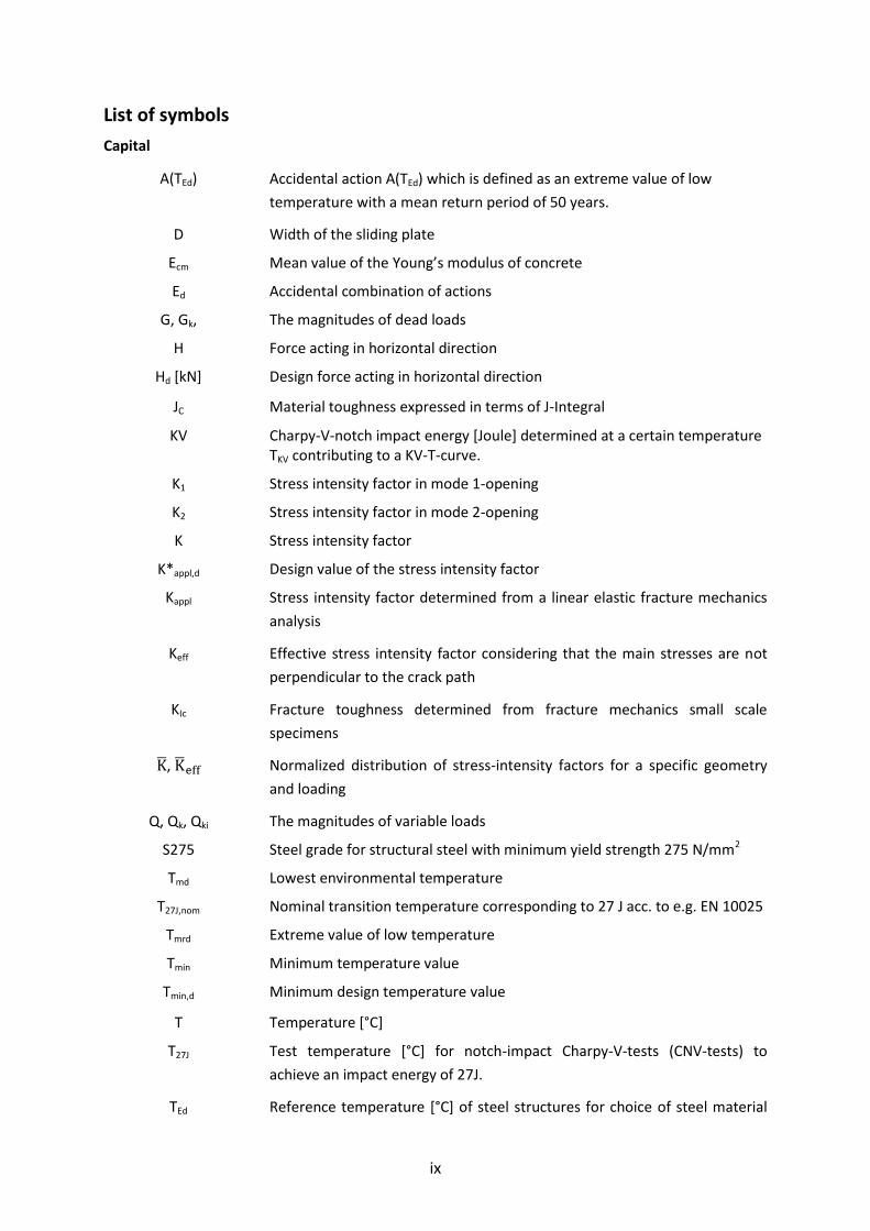
List of symbols
Capital
A(TEd)
Accidental action A(TEd) which is defined as an extreme value of low
temperature with a mean return period of 50 years.
D Width of the sliding plate
Ecm Mean value of the Young’s modulus of concrete
Ed Accidental combination of actions
G, Gk, The magnitudes of dead loads
H Force acting in horizontal direction
Hd [kN] Design force acting in horizontal direction
JC Material toughness expressed in terms of J-Integral
KV Charpy-V-notch impact energy [Joule] determined at a certain temperature TKV contributing to a KV-T-curve.
K1 Stress intensity factor in mode 1-opening
K2 Stress intensity factor in mode 2-opening
K Stress intensity factor
K*appl,d (9) Design value of the stress intensity factor
Kappl Stress intensity factor determined from a linear elastic fracture mechanics
analysis
Keff Effective stress intensity factor considering that the main stresses are not
perpendicular to the crack path
KIc Fracture toughness determined from fracture mechanics small scale
specimens
, Normalized distribution of stress-intensity factors for a specific geometry
and loading
Q, Qk, Qki The magnitudes of variable loads
S275 Steel grade for structural steel with minimum yield strength 275 N/mm2
Tmd Lowest environmental temperature
T27J,nom Nominal transition temperature corresponding to 27 J acc. to e.g. EN 10025
Tmrd Extreme value of low temperature
Tmin Minimum temperature value
Tmin,d Minimum design temperature value
T Temperature [°C]
T27J Test temperature [°C] for notch-impact Charpy-V-tests (CNV-tests) to
achieve an impact energy of 27J.
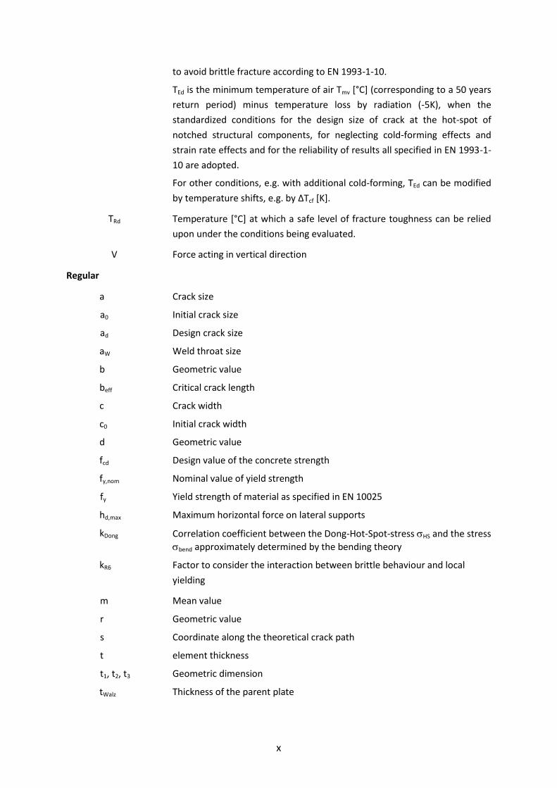
TEd Reference temperature [°C] of steel structures for choice of steel material
x
to avoid brittle fracture according to EN 1993-1-10.
TEd is the minimum temperature of air Tmv [°C] (corresponding to a 50 years
return period) minus temperature loss by radiation (-5K), when the
standardized conditions for the design size of crack at the hot-spot of
notched structural components, for neglecting cold-forming effects and
strain rate effects and for the reliability of results all specified in EN 1993-1-
10 are adopted.
For other conditions, e.g. with additional cold-forming, TEd can be modified
by temperature shifts, e.g. by ΔTcf [K].
TRd Temperature [°C] at which a safe level of fracture toughness can be relied
upon under the conditions being evaluated.
V Force acting in vertical direction
Regular
a Crack size
a0 Initial crack size
ad Design crack size
aW Weld throat size
b Geometric value
beff Critical crack length
c Crack width
c0 Initial crack width
d Geometric value
fcd Design value of the concrete strength
fy,nom Nominal value of yield strength
fy Yield strength of material as specified in EN 10025
hd,max Maximum horizontal force on lateral supports
kDong Correlation coefficient between the Dong-Hot-Spot-stress HS and the stress
bend approximately determined by the bending theory
kR6 Factor to consider the interaction between brittle behaviour and local
yielding
m Mean value
r Geometric value
s Coordinate along the theoretical crack path
t element thickness
t1, t2, t3 Geometric dimension
tWalz Thickness of the parent plate

xi
Greek symbols
a, c Crack growth increment from fatigue loading
Temperature shift [K] between the mean value of bi and the design fractile
m+3.03 σ of the distribution of bi, that represents the design value for
measured input values.
Tcf Temperature shift [K] in the notch impact energy-temperature diagram due
to cold-forming (cf), also designated as ΔTDCF.
TDCF See Tcf
T27J Temperature shift due to the inhomogeneity of material toughness in
through-thickness direction.
εΔT Temperature shift from high strain-rates
Tcf Temperature shift from cold-forming effects
Tr Temperature shift due to radiation loss of the structural component
T Temperature shift caused by K*appl,d
TR Additive safety element [K] in the limit state equation with TEd (action) and
TRd (resistance), that is determined from the evaluation of large scale
fracture mechanics tests and yields the required reliability of the design
equation that is underlying Table 2.1 in EN 1993-1-10.
Strain rate from dynamic actions
Reference value of the strain rate
cf Degree of cold forming in %
Poisson ratio
Correction factor to consider the interaction between stresses from
external loads and local residual stresses, that are reduced partially by local
plastic deformations.
Stress
1 First principal stress
bend,d The ultimate stress determined in a simplified way according to the elastic bending theory in the critical cross section perpendicular to the neutral axis
for action effects from loads factored with .
Ed Nominal stress on service level applied from external forces to the
structural component, in an accidental design situation according to EN
1993-1-10.
The leading action is the temperature TEd acting on a structural component
with a standardized severe notch situation and the design value of crack at
the hot spot of the notch. The external forces are from accompanying
actions (permanent loads and frequent values of variable loads without
partial factors). σEd does not include residual stresses.

xii
Residual stresses are included in the procedure of EN 1993-1-10 by two
means:
1. Local residual stresses from welding are included in the
evaluation procedure of fracture mechanical large scale tests.
2. Global residual stresses from restraints to the weld shrinkage of the
component are taken into account by a supplementary
nominal stress σS = 100 MPa.
y
Ed
f
Utilisation rate from external stresses. EN 1993-1-10 gives in its Table 2.1
information for admissible plate thickness for various steel grades,
temperatures TEd and for the utilisation rates: 0.25, 0.50 and 0.75.
gy Stress to the gross section that causes yielding of the net section.
HS Hot-Spot stress or structural stress
max Maximum stress
N Nominal stress
P Primary stress resulting from the accompanying external actions
S Residual stresses from restraints to the weld shrinkage of the component.
tot tot = P + S
1.1 Combination factor for frequent loads with a return period of 1 month
2,i Combination factor for „quasi-permanent“ loads

1
1 Objective
(1) The design rules for steel-structures apply in general to the upper shelf domain of the toughness-temperature diagram, where the steel material exhibits ductile behaviour. To consider the reduction of toughness in the transition range of the toughness-temperature diagram, steels should comply with a procedure for the choice of material to avoid brittle fracture. This procedure is based on a fracture mechanics safety-assessment for a scenario of hypothetical crack-distribution and loading at the time of lowest possible temperature of the structure.
(2) EN 1993-1-10 [2] gives a table for the choice of material which applies for the usual types of dimensions and details of structural steel components and includes the following parameters:
- the lowest possible temperature of the structure TEd,
- the structural detail at the critical spot which is contained in the detail classes in EN 1993-1-9-Fatigue.
The sketches illustrating the detail classes in EN 1993-1-9 are “cut-outs” from structural steel components, which include the “hot spots” at which fatigue cracks can be expected and are also used for the definition of “nominal stresses”, to which the fatigue resistance of the detail refers.
For the choice of material the same “hot spot” and the same definition of nominal
stresses Ed as in EN 1993-1-9 is used, however stresses are not related to “fatigue loads”, but to “frequent loads” according to EN 1990 – Basis of structural design. In the table in EN 1993-1-10 nominal stresses from frequent loads are classified as portion of the yield strength (0.25 fy, 0.50 fy, 0.75 fy).
- the plate thickness (product thickness) at the “hot-spot”.
(3) Bearings for bridges consist of small structural steel components usually produced by machining, the sizes of which frequently do not comply with the geometrical assumptions made for applying the bending theory for steel structures, the loading of which may be dependent on the deformation conditions of interfacing parts and the quality control during fabrication is subject to specific requirements (EN 1337).
(4) Therefore the prerequisites for the use of EN 1993-1-9 and EN 1993-1-10 do in general not apply, so that these standards are not useable for the choice of material for bearings without further information.
(5) This report therefore addresses the choice of steel material for bearings of bridges and gives for details specific to bearings the information for a “safe-sided” choice taking
reference to the lowest material temperature TEd, the type of detail, the stress level Ed and the relevant material thickness at the hot spot.
(6) For deriving of the tables in this report the same fracture mechanics procedure is used as in EN 1993-1-10 however with some modifications of the procedure which comprise:
1. The magnitude and the shape of the hypothetical design crack, because fatigue effects as considered in EN 1993-1-10 are not relevant.
2. Definition of “nominal stress” Ed for the “hot-spot” which cannot be easily determined in the conventional way by force divided by area as specified in
EN 1993-1-9. For the definition of “nominal stresses” Ed two methods are used:

2
i. method for assessing structural components with Finite Elements.
ii. simplified method using the assessment with assumption of the “bending theory”.
(7) The report is structured into the following sections:
1. Fracture mechanics assessment as used in EN 1993-1-10 to avoid brittle fracture.
2. Bearings for bridges, types of bearings and specification, standard components of bearings referred to in the assessment.
3. Modifications of the fracture mechanics assessment as used in EN 1993-1-10 for the specific purposes of bridge bearings.
4. Numerical studies and results.
5. Proposal for a standardisation when using Finite Elements.
6. Proposal for referring to ultimate stress assessments according to the bending theory.
7. Worked example.

3
2 Fracture mechanics safety assessment to avoid brittle fracture as used in EN 1993-1-10
2.1 General
(1) The procedure for choosing the steel to avoid brittle fracture in EN 1993-1-10 [2] is explained in the JRC-Scientific and Technical Report [3] related to this standard.
(2) In the following an abridged version is given to make the modifications for bridge bearings understandable.
2.2 Basics of the fracture mechanics procedure
(1) The design equation with fracture mechanics properties (here stress intensity factors K) reads
K*appl,d ≤ Kmat,d (2-1)
where
K*appl,d is the design value of action effect at the tip of the
hypothetical crack which is assumed to be located at the most severe notch of the structure component.
Local plastic zones at the crack tip are taken into account by the correction value kR6 according to the simplified Failure Assessment Diagram (FAD). The value K*appl,d therefore reads
K*appl,d = Kappl / (kR6 - ) (2-2)
where
Kappl is determined from a linear elastic fracture mechanics analysis
kR6 is a factor to consider the interaction between brittle behaviour and local yielding, see [2]
is a correction factor to consider the interaction between stresses from external loads and local residual stresses, that are reduced partially by local plastic deformations.
(2) The fracture mechanics resistance is defined by KMat,d. That “toughness property” can be determined experimentally. Another option is a numerical determination on the basis of correlations to “toughness properties” specified in the material standards or given in the material certificates. The “toughness properties” in the material standards are given by minimum requirements for Charpy-V-impact energies at a certain testing temperature.
(3) To standardize the fracture mechanics assessment procedure and to adapt it to the toughness properties T27J specified in the product standards, the design equation based on stress-intensity factors has been transformed to a design equation based on temperatures

4
TEd ≥ TRd (2-3)
(4) The temperature term TEd contains actions from the temperature of the structural component, influences from the stress-level and strain-rate, the shape and dimensions of the structural component and the size of the hypothetical crack-like flaw.
TEd = Tmd + Tr + T + TR + εΔT + Tcf (2-4)
where
Tmd is the lowest environmental temperature
Tr is the radiation loss of the structural component: Tr = -5 K
TR is an additive safety element in terms of a temperature shift
T is the temperature shift caused by K*appl,d, i.e. by the
influence of stress level, geometry of the detail and crack configuration:
C12070
1025
b20)(K
ln52ΔT
1/4
effdappl,
*
σ
εΔT is the temperature shift from high strain-rates where:
1,5
0
y
εε
εln
550
(t)f-1440ΔT
fy(t) is the yield strength depending on plate thickness t
ε is the strain rate from dynamic actions
0ε = 0.0001 s-1 is the reference value to define static actions
Tcf is the temperature shift from cold-forming effects:
Tcf = 0 for cf ≤ 2%
Tcf = -3 x cf for cf > 2%
where cf is the degree of cold forming (plastic strain) in %
(5) The resistance side includes the material toughness expressed by
TRd = (T27J – 18) + T27J (2-5)
where
T27J is the testing temperature, for which the Charpy-V-notch impact energy attains 27 Joule
T27J is the temperature shift due to the inhomogeneity of material toughness in through-thickness direction. It should be used

5
where the hypothetical crack penetrates into the inner core area of the product . The inner core area for plates is defined as the inner third of the plate thickness.
2.3 Design situation
(1) For developing EN 1993-1-10 for the choice of material to avoid brittle fracture an accidental design situation (case A1 - A2 - A3 in Figure 2-1) has been assumed that includes the following conditions:
- The assessment is carried out in the region of elastic fracture mechanics (KIc-region) in the lower part of the toughness-temperature diagram.
- The structural component has a crack at the critical hot spot and the crack has reached a critical size (the crack is understood as an initial crack from production overlooked at production control which has increased by fatigue effects during service).
- The temperature of the structural component has obtained a minimum value Tmin, at which the value of material toughness has reached its minimum value JC (point A1 in Figure 2-1). The temperature TEd on the action side may be further reduced by the temperature shifts from the influence of cold-forming or impact loads.
- The magnitudes of variable loads Q and of the temperature of the structural component are statistically independent on each other. Therefore the accidental combination of action includes Tmin,d as the dominant action, which is combined
with accompanying frequent loads GK + 1 QK which produce the stress-level from external loads (point A2 in Figure 2-1).
- Because of the lower level of the frequent loads the stresses in this accidental
combination of actions Ed = (GK + 1 QK) are in general in the elastic range (point A3 in Figure 2-1).
Figure 2-1: Design situations for the choice of material to avoid brittle fracture according to EN 1993-1-10

6
(2) The accidental combination of actions, which is fully described by
Ed = E {A [TEd] “+” Gk “+”1,1 Qk1 ”+”2,i Qki} (2-6)
is justified by the fact, that a series of adverse influences (low temperature simultaneously with a hypothetical crack overlooked at the most severe location of the structural component) are all combined together.
(3) The accidental action A(TEd) is defined as an extreme value of low temperature with a mean return period of 50 years, e.g. for Germany Tmrd = -30 °C including radiation loss.
(4) The accompanying actions are stresses from permanent and variable loads. Because of the limited duration of the accidental extreme temperature the accompanying actions will not take their extreme values but the “frequent values” due the probability of occurrence.
(5) From the accompanying external actions the nominal values are determined using the following load-combination
P = {Gk “+” 1,1 Qk1 ”+” 2,i Qki} (2-7)
where
1,1 is the combination factor for frequent loads with a return
period of 1 month
2,i is the combination factor for „quasi-permanent“ loads
(6) In addition to these “primary” nominal stresses P also “secondary stresses” S from residual stresses and unforeseen restraints from the assembly of the structure have been taken into account in preparing the table for the choice of material in EN 1993-1-10, so that
tot = P + S (2-8)
where
P is the nominal stress from the external loads, see above
S is the residual stress defined as “global”. In preparing the
table in EN 1993-1-10 a lump value S = 100 N/mm² has been used. “Local” residual stresses, which occur in the welded area at the hot spot and may be reduced by local cracking need not to be specified as they are considered already in the model uncertainty when the numerical assessment procedure was calibrated to the results of fracture mechanics tests undertaken with large-size welded test- specimens.
(7) The values in the table of EN 1993-1-10 refer to the stress-level Ed = P only, so that for
using the table S needs not to be further considered.
(8) Where Ed is a compression stress, the structural component should be assessed for the
lowest class of tension stress Ed = 0.25 fy.

7
2.4 Assumptions for the structural detail and the magnitude of hypothetical crack
(1) EN 1993-1-10 has been initially developed for the choice of material for steel bridges; therefore the assumptions for the choice of a reference detail and the position and magnitude of the hypothetical cracks were mainly influenced by typical bridge structures.
(2) The reference detail with geometrical parameters chosen for EN 1993-1-10 is a plate in tension with a welded longitudinal attachment as given in Figure 2-2. This detail is typical for bridge structures; because of the geometrical notch effect it represents an enhanced risk for starting brittle fracture. This detail is also included in the detail-classes in EN 1993-1-9 [5]. For determining K*
appl,d particular ranges of dimensions (e.g. length of stiffener in relation to plate thickness and plate width, angle and size a of fillet weld) were assumed that are representative for the use in bridges.
Figure 2-2: Reference structural detail for calculating K*appl,d for the choice of material in EN 1993-1-10
(3) Other detail classes as specified in EN 1993-1-9 are covered by this reference detail and the assessment method applied for it, so that EN 1993-1-10 is safe sided for all fatigue details in EN 1993-1-9. In case of structural details that cannot be classified to EN 1993-1-9 the table for choice of material in EN 1993-1-10 is not applicable.
(4) The assumption for a crack-like flaw is a semi elliptical surface crack at the position of the largest stress-concentration at the end of the longitudinal stiffener. Figure 2-3 shows the cross-section of a rectangular plate with a semi-elliptical crack. The ratio of the crack depth a to the crack-width c has been determined for this reference detail with a/c = 0.4.
Figure 2-3: Assumption of a semi-elliptical surface crack in a plate with rectangular cross-section
(5) The magnitude of the design values ad and cd is determined from two components:
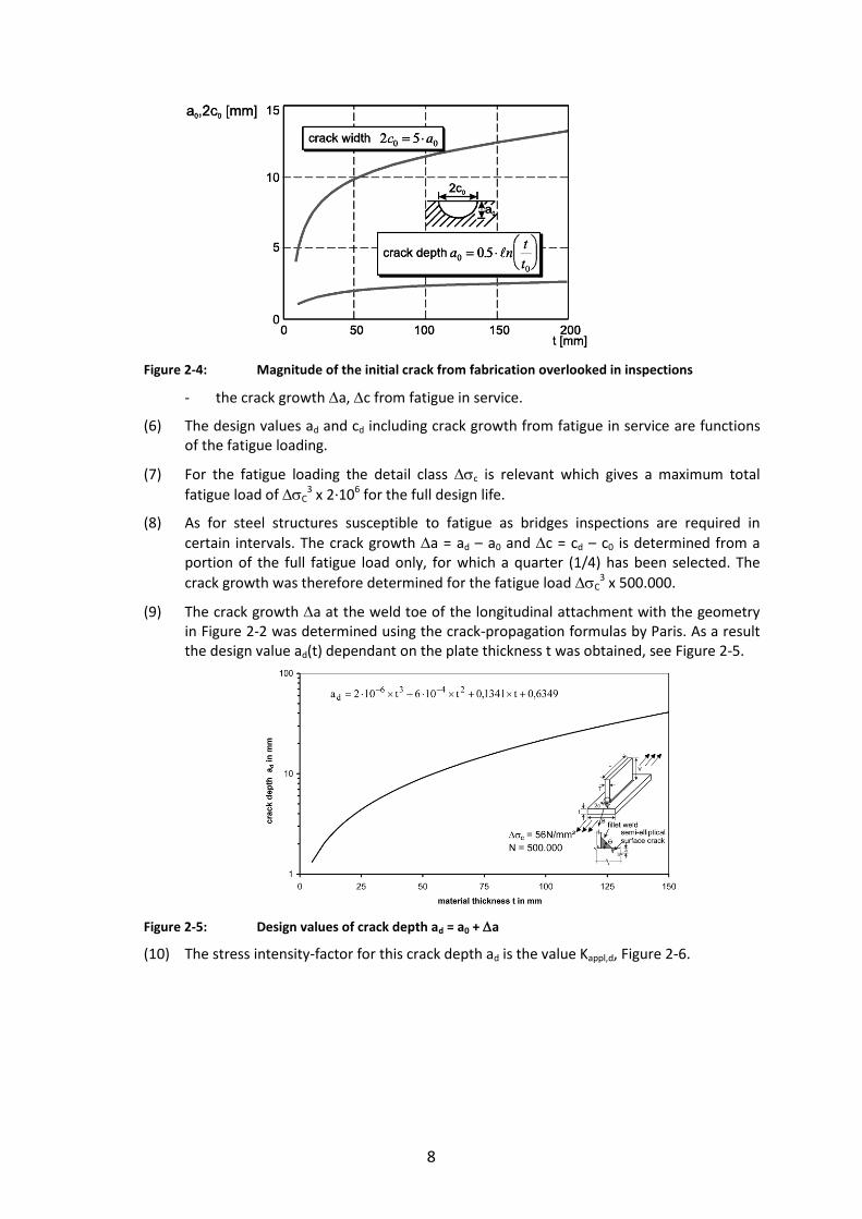
- the initial crack size with the crack depth a0 and the crack width c0 is determined in dependence of the product thickness (plate thickness) according to Figure 2-4. This magnitude is considered to be detectable in inspections during production see Figure 2-7 with the usual testing methods used in steel construction.
ca a
ct
B
8
Figure 2-4: Magnitude of the initial crack from fabrication overlooked in inspections
- the crack growth a, c from fatigue in service.
(6) The design values ad and cd including crack growth from fatigue in service are functions of the fatigue loading.
(7) For the fatigue loading the detail class c is relevant which gives a maximum total
fatigue load of C3 x 2∙106 for the full design life.
(8) As for steel structures susceptible to fatigue as bridges inspections are required in
certain intervals. The crack growth a = ad – a0 and c = cd – c0 is determined from a portion of the full fatigue load only, for which a quarter (1/4) has been selected. The
crack growth was therefore determined for the fatigue load C3 x 500.000.
(9) The crack growth a at the weld toe of the longitudinal attachment with the geometry in Figure 2-2 was determined using the crack-propagation formulas by Paris. As a result the design value ad(t) dependant on the plate thickness t was obtained, see Figure 2-5.
Figure 2-5: Design values of crack depth ad = a0 + a
(10) The stress intensity-factor for this crack depth ad is the value Kappl,d, Figure 2-6.

9
Figure 2-6: Stress intensity factor Kappl,d calculated for the design crack depth ad in figure 2-5
(11) The interpretation of the initial crack size a0/c0 as a flaw “overlooked in the production control” is justified by the fact, that the magnitudes of a0/c0 are detectable during crack-inspections. Figure 2-7 gives the functions 2c0 of the initial crack and 2cd of the design crack in relation to the limits for detectability by visual inspection, colour penetration test, ultrasonic inspection and magnetic particle inspection.
Figure 2-7: Assumptions for initial values and design values of crack size and detectability by testing methods
(12) Hence the initial crack assumed is detectable by production control and can be assumed to be accidentally overlooked.
2.5 Table 2.1 of EN 1993-1-10
(1) Table 2.1 in EN 1993-1-10 gives the results of the fracture mechanics safety assessments, see Figure 2-8. It is applicable for all details listed in EN 1993-1-9.

10
Figu
re 2
-8:
Tab
le 2
.1 in
EN
19
93
-1-1
0, h
ere
wit
h a
n e
xte
nsi
on
to
co
ver
a la
rge
r te
mp
era
ture
ran
ge T
Ed [
4]
Re
fere
nce
te
mp
era
ture
TEd
[°C
]
-12
0
Ed
= 0
,25
fy(
t)
31
35
42
28
32
39
43
55
23
27
33
37
47
33
42
28
30
36
39
47
16
19
21
25
28
34
refe
ren
ce t
em
per
atu
re
T Ed
T*Ed
= T
Ed +
T c
f
No
te: T
he
valu
es in
th
is t
ab
le a
re f
or
som
e p
ara
met
ers
slig
htl
y d
iffe
ren
t to
th
ose
giv
en in
Ta
ble
2.1
of
EN 1
99
3-1
-10
. In
a f
utu
re r
evis
ion
of
Tab
le 2
.1 o
f EN
199
3-1
-10
th
e va
lues
of
Fig
ure
2-8
co
uld
be
ad
op
ted
.
-11
0
33
39
47
30
35
43
48
62
25
30
37
41
54
37
48
31
34
41
45
54
18
22
24
29
32
39
-10
0
35
42
53
32
39
49
55
71
27
33
42
47
62
42
56
36
39
47
53
63
21
25
28
34
38
46
-90
39
47
59
35
43
55
62
82
30
37
47
54
72
48
65
41
45
54
61
74
24
29
32
39
44
55
-80
42
53
67
39
49
62
71
95
33
42
54
62
83
55
75
47
52
63
71
86
28
34
38
46
52
65
-70
47
59
77
43
55
71
81
10
9
37
47
62
71
97
64
88
54
61
74
83
10
1
32
39
44
55
62
77
-60
53
67
88
49
62
82
94
12
6
42
54
72
83
11
2
75
10
3
63
71
86
97
11
8
38
46
52
65
73
91
-50
59
77
10
1
55
71
95
10
8
14
5
47
62
83
96
13
0
87
11
9
74
82
10
1
11
4
13
7
44
55
62
77
87
10
7
-40
67
88
11
6
62
82
10
9
12
5
16
7
54
72
97
11
1
15
0
10
2
13
9
86
96
11
8
13
2
15
9
52
65
73
91
10
2
12
6
-30
77
10
1
13
4
71
95
12
6
14
4
19
1
62
83
11
2
12
9
17
3
11
8
16
0
10
1
11
3
13
7
15
3
18
3
62
77
87
10
7
12
0
14
7
-20
88
11
6
15
4
82
10
9
14
5
16
5
19
9
72
97
13
0
14
9
19
8
13
8
18
5
11
8
13
1
15
9
17
7
19
9
73
91
10
2
12
6
14
1
17
1
-10
10
1
13
4
17
6
95
12
6
16
7
18
9
19
9
83
11
2
15
0
17
2
19
9
15
9
19
9
13
7
15
2
18
3
19
9
19
9
87
10
7
12
0
14
7
16
4
19
7
0
11
6
15
4
19
9
10
9
14
5
19
1
19
9
20
2
97
13
0
17
3
19
7
19
9
18
3
19
9
15
9
17
6
19
9
19
9
19
9
10
2
12
6
14
1
17
1
18
9
19
9
10
13
4
17
6
19
9
12
6
16
7
19
9
19
9
22
9
11
2
15
0
19
8
19
9
21
0
19
9
19
9
18
3
19
9
19
9
19
9
22
2
12
0
14
7
16
4
19
7
19
9
19
9
-12
0
Ed
= 0
,50
fy(t
)
16
19
24
14
17
21
23
31
10
13
16
18
25
15
21
12
14
16
19
23
5
7
8
10
11
14
-11
0
18
21
27
15
18
24
27
36
11
14
18
21
29
17
24
14
16
19
22
27
6
8
9
12
13
17
-10
0
19
24
31
17
21
27
31
42
13
16
21
24
34
20
29
16
18
23
26
33
8
10
11
14
16
21
-90
21
27
35
18
24
31
36
49
14
18
25
28
40
24
34
19
22
27
31
39
9
12
13
17
20
26
-80
24
31
41
21
27
36
42
58
16
21
29
34
48
29
41
23
26
33
38
47
11
14
16
21
24
31
-70
27
35
47
24
31
42
49
69
18
25
34
40
57
34
49
27
31
39
45
57
13
17
20
26
30
38
-60
31
41
55
27
36
49
58
81
21
29
40
47
68
41
59
33
37
47
54
68
16
21
24
31
36
47
-50
35
47
65
31
42
58
68
96
25
34
48
56
80
49
71
39
45
57
65
82
20
26
30
38
44
57
-40
41
55
77
36
49
69
81
113
29
40
57
67
96
58
84
47
54
68
78
98
24
31
36
47
54
69
-30
47
65
90
42
58
81
95
133
34
48
68
80
113
70
100
57
65
82
94
116
30
38
44
57
65
84
-20
55
77
106
49
69
96
112
156
40
57
80
95
133
83
119
68
78
98
111
137
36
47
54
69
79
100
-10
65
90
125
58
81
113
132
181
48
68
96
112
156
99
140
82
93
116
132
160
44
57
65
84
95
120
0
77
106
146
69
96
133
154
199
57
80
113
132
181
118
164
98
110
137
155
186
54
69
79
100
114
142
10
90
125
169
81
113
156
179
199
68
96
133
155
199
139
190
116
130
160
180
199
65
84
95
120
135
166
-12
0
Ed
= 0
,75
fy(
t)
9
11
14
7
9
11
13
18
5
6
8
9
14
7
11
6
6
8
10
12
- 1
2
4
5
7
-11
0
10
12
16
8
10
13
15
22
5
7
10
11
16
9
13
7
8
10
12
15
- 2
3
5
6
8
-10
0
11
14
18
9
11
15
18
26
6
8
11
13
20
11
16
8
9
12
14
18
2
4
5
7
8
11
-90
12
16
21
10
13
18
21
31
7
10
14
16
24
13
20
10
12
15
18
23
3
5
6
8
10
13
-80
14
18
25
11
15
22
25
37
8
11
16
19
29
16
24
12
14
18
22
28
5
7
8
11
13
17
for
ho
t-fi
nis
hed
sec
tio
ns
fo
r co
ld-f
orm
ed s
ecti
on
s:
-70
16
21
30
13
18
26
31
45
10
14
20
23
35
19
29
15
17
23
27
34
6
8
10
13
16
21
-60
18
25
36
15
22
31
37
54
11
16
24
28
43
24
36
18
21
28
33
42
8
11
13
17
20
27
-50
21
30
43
18
26
37
44
65
14
20
29
35
52
29
44
23
26
34
40
52
10
13
16
21
25
34
-40
25
36
51
22
31
45
53
78
16
24
35
42
63
36
54
28
32
42
49
63
13
17
20
27
31
42
-30
30
43
62
26
37
54
64
94
20
29
43
51
76
44
66
34
40
52
60
77
16
21
25
34
39
52
-20
36
51
74
31
45
65
77
112
24
35
52
62
92
53
80
42
49
63
73
93
20
27
31
42
48
64
-10
43
62
89
37
54
78
93
13
4
29
43
63
75
11
0
65
96
52
60
77
89
11
2
25
34
39
52
60
78
0
51
74
10
6
45
65
94
11
1
15
8
35
52
76
91
13
1
79
11
5
63
73
93
10
7
13
3
31
42
48
64
73
94
10
62
89
126
54
78
112
132
185
43
63
92
109
155
95
137
77
88
112
128
157
39
52
60
78
89
113
Ch
arp
y
ener
gy
CV
N J m
in
27
27
27
27
27
27
40
27
27
27
27
40
27
40
27
30
40
30
27
30
40
30
40
30
40
30
at T
[°C
]
+20
0
-20
+20
0
-20
-20
-50
+20
0
-20
-20
-50
-20
-50
-20
-20
-40
-50
-60
0
-20
-20
-40
-40
-60
Sub
-
grad
e
JR
J0
J2
JR
J0
J2
M, N
ML,
NL
JR
J0
J2
K2,
M,N
ML,
NL
M, N
ML,
NL
Q
M, N
QL
ML,
NL
QL1
Q
Q
QL
QL
QL1
QL1
Stee
l
grad
e
S23
5
S27
5
S35
5
S42
0
S46
0
S69
0
11
3 Structural bearings for bridges, types, product specification and selection of standard components for fracture mechanics assessments
3.1 Types of bearings and product specifications
(1) Bearings for bridges are elements allowing rotation between two members of a structure and transmitting the loads defined in the relevant requirements as well as preventing displacements (fixed bearings) allowing displacements in only one direction (guided bearings) or in all directions of a plane (free bearings) as required.
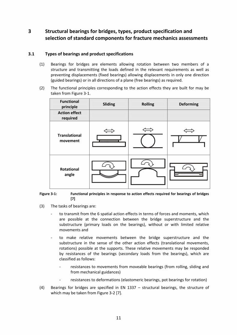
(2) The functional principles corresponding to the action effects they are built for may be taken from Figure 3-1.
Functional principle
Sliding Rolling Deforming
Action effect required
Translational movement
Rotational angle
Figure 3-1: Functional principles in response to action effects required for bearings of bridges [7]
(3) The tasks of bearings are:
- to transmit from the 6 spatial action effects in terms of forces and moments, which are possible at the connection between the bridge superstructure and the substructure (primary loads on the bearings), without or with limited relative movements and
- to make relative movements between the bridge superstructure and the substructure in the sense of the other action effects (translational movements, rotations) possible at the supports. These relative movements may be responded by resistances of the bearings (secondary loads from the bearings), which are classified as follows:
- resistances to movements from moveable bearings (from rolling, sliding and from mechanical guidances)
- resistances to deformations (elastomeric bearings, pot bearings for rotation)
(4) Bearings for bridges are specified in EN 1337 – structural bearings, the structure of which may be taken from Figure 3-2 [7].

12
Figure 3-2: Structure of EN 1337-Structural bearings
(5) Table 3-1 gives an example for the relationship between the various parts of EN 1337 to the parts of former DIN 4114 (German standard) the contents of which has been fully or partially withdrawn. Such comparison may be made for any other National Standard.
Table 3-1: Survey on EN 1337 and relation to DIN 4141
Standard Title Status and remarks
DIN EN 1337-1,
Februay 2001
General design rule Standard in force,
no product standard,
replaces partly DIN V 4141 – 1, -2, -3
DIN EN 1337-2,
July 2004
Sliding elements Standard in force,
no product standard
DIN EN 1337-3,
July 2005
Product standard
Elastomeric bearing Standard in force,
replaces DIN 4141-14-14/A1, -140/A1,
partly -15, -140, -150
DIN EN 1337-4,
April 2004
Product standard
Roller bearings Standard in force,
does not replace any DIN-standard
DIN EN 1337-5,
July 2005
Product standard
Pot bearings Standard in force,
does not replace any DIN-standard
DIN EN 1337-6,
June 2004
Product standard
Rocker bearings Standard in force,
does not replace any DIN-standard

13
Table 3-1: continued
Standard Title Status and remarks
DIN EN 1337-7,
August 2003
Product standard
Spherical and
cylindrical PTFE
bearings
Standard in force,
does not replace any DIN-standard
DIN 1337-8,
January 2008
Product standard
Guided bearings and
restraint bearings
Standard in force,
replaces DIN 4141-13
DIN EN 1337-9,
April 1998
Protection Standard in force,
no product standard,
replaces partly DIN V 4141-1
DIN EN 1337-10,
November 2003
Inspection and
maintenance
Standard in force
replaces partly DIN V 4141-1
DIN EN 1337-11,
April 1998
Transport storage and
installation
Standard in force
replaces DIN 4141-4
(6) EN 1337 deals exclusively with the construction products “bearings”. EN 1337 does not deal with the installation and supplementary equipments of bearings as “anchor plates” and with other requirements which were contained e.g. in Germany in “Allgemeine Bauaufsichliche Zulassungen” (General technical Approvals) and “Lager-Richtzeichungen” (Guidance drawings for bearings) before EN 1337 got into force, see Figure 9-4. As these requirements also control the quality of the bearings with respect to durability and safety of use, they are now summarized in the “Allgemeine Bauaufsichtliche Zulassungen” of the Deutsche Institut für Bautechnik (DIBt) in addition to EN 1337, e.g.
- Z-16.7-444 “Ausstattung von RWSH-Brückenlagern mit CE-Kennzeichung“ (Equipment of RWSH bridge-bearings with CE-marking) or
- Z-16.4-436 or ETA-06/0131 „Maurer MSM®-Kalottenlager“ (Maurer MSM®-spherical and cylindrical PTFE-bearings). The bearing can be installed with the supplementary equipment specified in this Technical Approvals directly into the bridge structure without further additions.
This example should be used to check the situation in other regulatory environments.
(7) The choice of material for the supplementary equipment, e.g. anchoring parts, fasteners, fill plates, wedge plates and additional plates, the material of which should comply with the EN-Standards and be suitable for the purpose and welding, should be according to EN 1993 – Part 2 [9].
(8) The effective temperature of the bearings for determining the application field in accordance with EN 1337 [7] is the minimum and maximum air-temperature.
(9) The aim of this report is the choice of material for steel components of bearings, which complements the rules for choice in EN 1993 – Part 2.
14
3.2 Selection of standard components of bearings for facture mechanics assessments
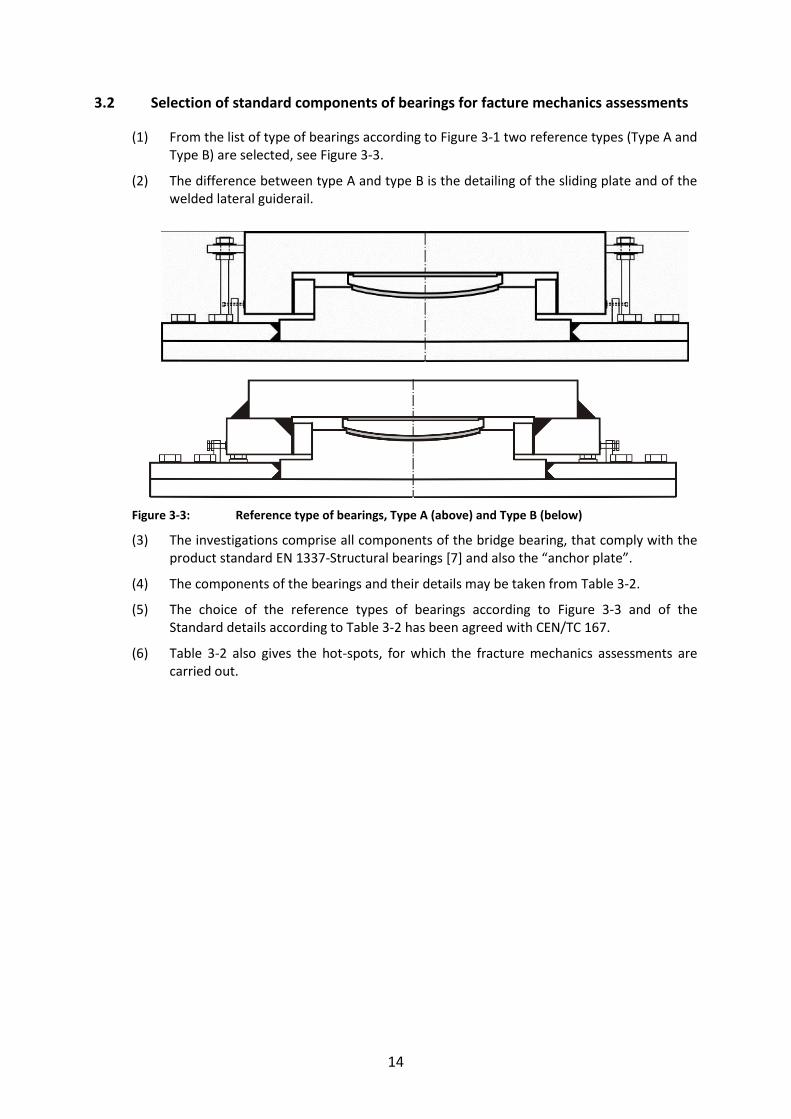
(1) From the list of type of bearings according to Figure 3-1 two reference types (Type A and Type B) are selected, see Figure 3-3.
(2) The difference between type A and type B is the detailing of the sliding plate and of the welded lateral guiderail.
Figure 3-3: Reference type of bearings, Type A (above) and Type B (below)
(3) The investigations comprise all components of the bridge bearing, that comply with the product standard EN 1337-Structural bearings [7] and also the “anchor plate”.
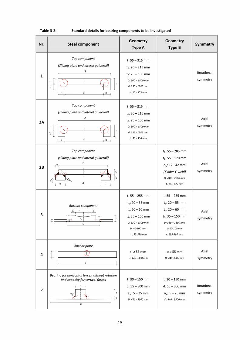
(4) The components of the bearings and their details may be taken from Table 3-2.
(5) The choice of the reference types of bearings according to Figure 3-3 and of the Standard details according to Table 3-2 has been agreed with CEN/TC 167.
(6) Table 3-2 also gives the hot-spots, for which the fracture mechanics assessments are carried out.
15
Table 3-2: Standard details for bearing components to be investigated
Nr. Steel component Geometry
Type A
Geometry
Type B Symmetry
1
Top component
(Sliding plate and lateral guiderail)
t: 55 – 315 mm
t1: 20 – 215 mm
t2: 25 – 100 mm
D: 500 – 1800 mm
d: 355 - 1385 mm
b: 50 - 505 mm
Rotational
symmetry
2A
Top component
(sliding plate and lateral guiderail)
t: 55 – 315 mm
t1: 20 – 215 mm
t2: 25 – 100 mm
D: 500 – 1800 mm
d: 355 - 1385 mm
b: 50 - 500 mm
Axial
symmetry
2B
Top component
(sliding plate and lateral guiderail)
t1: 55 – 285 mm
t2: 55 – 170 mm
aw: 12 - 42 mm
(K oder Y-weld)
D: 440 – 2580 mm
b: 55 - 570 mm
Axial
symmetry
3
Bottom component
t: 55 – 255 mm
t1: 20 – 55 mm
t2: 20 – 60 mm
t3: 35 – 150 mm
D: 330 – 1800 mm
b: 40-100 mm
r: 135-590 mm
t: 55 – 255 mm
t1: 20 – 55 mm
t2: 20 – 60 mm
t3: 35 – 150 mm
D: 330 – 1800 mm
b: 40-100 mm
r: 135-590 mm
Axial
symmetry
4
Anchor plate
t: ≥ 55 mm
D: 440-3300 mm
t: ≥ 55 mm
D: 440-3300 mm
Axial
symmetry
5
Bearing for horizontal forces without rotation and capacity for vertical forces
t: 30 – 150 mm
d: 55 – 300 mm
aw: 5 – 25 mm
D: 440 - 3300 mm
t: 30 – 150 mm
d: 55 – 300 mm
aw: 5 – 25 mm
D: 440 - 3300 mm
Rotational
symmetry
16
4 Modification of the fracture mechanics safety assessment
4.1 General
(1) The fracture mechanics safety assessment as used in EN 1993-1-10 had to be adapted to the particularities of steel components for bearings in the following respect:
1. Definition of structural parameters that are typical for steel bearings
2. Definition of “nominal stresses” Ed in compliance with the geometry and the loading of the steel components.
4.2 Definition of structural parameters typical for bearings
4.2.1 Model for fracture mechanics assessments
(1) The structural steel components of bearings are either rotationally-symmetric (e.g. for spherical bearings with restraints for all axes) or prismatic (e.g. for cylindrical bearings with unidirectional movable sliding).
(2) For simplifying the calculations for both the rotationally-symmetric and prismatic type of bearings a strip is selected, that in the case of rotationally-symmetric design represents a sector and in the case of prismatic design represents a parallel section transverse to the generator.
In compliance with this simplified model the assumption for the size of the initial crack is that of a continuous notch along the full perimeter of the component for rotationally- symmetric components and as linearly distributed along the length of the generator for axisymmetric components. Such a crack distribution can be interpreted as resulting from an accidental defect imposed during machining or welding.
4.2.2 Shape and magnitude of the design crack
(1) In the strips (either sectors or sections) used as fracture mechanics models the crack depth is constant along the width of the strips and also straight-lined.
It is located at the spot of high stress-concentration, where - in case of fatigue - fatigue cracks could be expected. The crack depth corresponds to the initial crack size in EN 1993-1-10, see Figure 2-4. As bearings considered in this report are not subject to fatigue, the design value of the initial crack depth ad corresponds to the value of the crack a0
0
0dt
t1ln
2
1aa for t <15 mm (4-1)
0
0dt
tln
2
1aa for t ≥ 15 mm (4-2)
where t0 = 1 mm.
(2) For the detectability of such cracks during production control see Figure 2-7.
4.2.3 Assumption for residual stresses
(1) EN 1993-1-10 provides two types of residual stresses:

17
1. Residual stresses in the local region around the welds at the hot spot from weld shrinkage which enhance the stresses in the welds and are reduced where cracks occur (primary residual stresses).
2. Far distance effect of weld shrinkage due to restraints resulting from the boundary conditions of the structural component (secondary residual stresses). These residual stresses are superimposed to the stresses from external loads and are not affected by local cracking at the hot spot.
(2) For the reference types A and B of bearings (see Figure 3-3) the occurrence of significant secondary stresses is improbable. For reference type B (welded alternative to type A) there may be large weld thicknesses (e.g. aw = 42 mm) which will cause large primary residual stresses.
(3) In EN 1993-1-10 it is assumed that the primary residual stresses are covered by the calibration of the fracture mechanics assessment procedure to the results of fracture mechanics tests with typical large scale welded test specimens that include those
primary stresses. For secondary residual stresses an assumption of S = 100 MPa has been made.
(4) For the steel components of bearings it is assumed that primary residual stresses that may be larger than those assumed in EN 1993-1-10 and other unidentified effects from restraints both for type A and type B bearings will be covered by the use of a secondary
residual stress of S = 100 MPa.
4.2.4 Critical crack length beff
(1) The term T (see 2.2 (4)) contains a function
41
eff
effb
25)b(f
(4-3)
which takes into account the effect of the length of cracks on the probability of temperature shift and which has been derived from the “weakest-link-model”. The term beff refers to the length of the critical crack front. [6] contains information what values beff should be used depending of the type of crack. For this case of strip-models (sectorial and sectional) with continuous crack fronts the information in [6] are not usable.
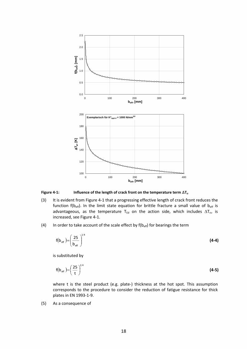
(2) Figure 4-1 shows the influence of the length of the crack front beff on the function f (beff)
18
Figure 4-1: Influence of the length of crack front on the temperature term T
(3) It is evident from Figure 4-1 that a progressing effective length of crack front reduces the function f(beff). In the limit state equation for brittle fracture a small value of beff is
advantageous, as the temperature TEd on the action side, which includes T, is increased, see Figure 4-1.
(4) In order to take account of the scale effect by f(beff) for bearings the term
41
eff
effb
25bf
(4-4)
is substituted by
41
efft
25bf
(4-5)
where t is the steel product (e.g. plate-) thickness at the hot spot. This assumption corresponds to the procedure to consider the reduction of fatigue resistance for thick plates in EN 1993-1-9.
(5) As a consequence of
0.0
0.5
1.0
1.5
2.0
2.5
0 100 200 300 400beff, [mm]
f(bef
f), [m
m]
100
120
140
160
180
200
0 100 200 300 400beff, [mm]
T
, [K
]
Exemplarisch für K*appl.d = 1000 N/mm3/2

19
41
efft
25bf
the temperature TEd (≥ TRd) is the more reduced the thicker the plate thickness is.
4.2.5 Determination of the stress limit gy
(1) The stress limit gy is the stress to the gross section that causes yielding of the net section. This value is needed to determine the correction function kR6 from the CEGB-R6-
diagram. For the standard case of a straight surface crack, see Figure 4-2, gy may be determined according to [6] from
t
atft ygy 1 (4-6)
Figure 4-2: Definition of net section yielding
4.2.6 Inhomogenity of toughness in through-thickness direction
(1) Steel components of bearings may be produced from thicker plates by machining. The thickness of the plates may be in the order of magnitude of the thickness of the machined steel component, so that the steel properties of the plate apply. The thickness of the plate may however be greater, so that the position of the steel component in through thickness direction controls whether the properties of the thick plate according to the certificate (position of test sample close to the surface) apply or not.
(2) In case the position of the steel component is outside the position of the test sample for the certificate for the thick plate, particular material tests from the inner part from which the steel component is produced should be considered.
(3) In the fracture mechanics assessment procedure to avoid brittle fracture a “normal” reduction of material toughness in through-thickness direction is taken into account by the term
8,125,7ln1,2tanh9,1227 tT J (4-7)
This case applies where the thickness of plate to be machined is in the order of the magnitude of the thickness of the steel component.
By the term T27J the temperature TRd on the resistance side is increased with unfavourable effects.
(4) For the assessment of steel components of bearings the term T27J is generally used to model a certain “normal inhomogeneity”, even if the hypothetical crack would not enter into the core part of the material (inner third of material thickness).
(5) A condition for “normal inhomogeneity” for larger thickness of material is, that the steel-properties of the inner parts of thick plates do not “significantly” deviate from the properties at the spot where the sample is taken. Such significant deviations may e.g. be caused by insufficient rolling technology in the steel mill.
20
(6) As long as EN 10025 does not provide options for specifications of the inner part of thick products, additional tests should be agreed for the material delivery.
4.2.7 Strain rate effects, cold forming
(1) Temperature shifts from high strain-rates or from high degrees of cold-forming are not relevant for bearings and therefore are ignored.
4.3 Definition of the nominal values Ed from the geometry and loading of steel components of bearings
4.3.1 General
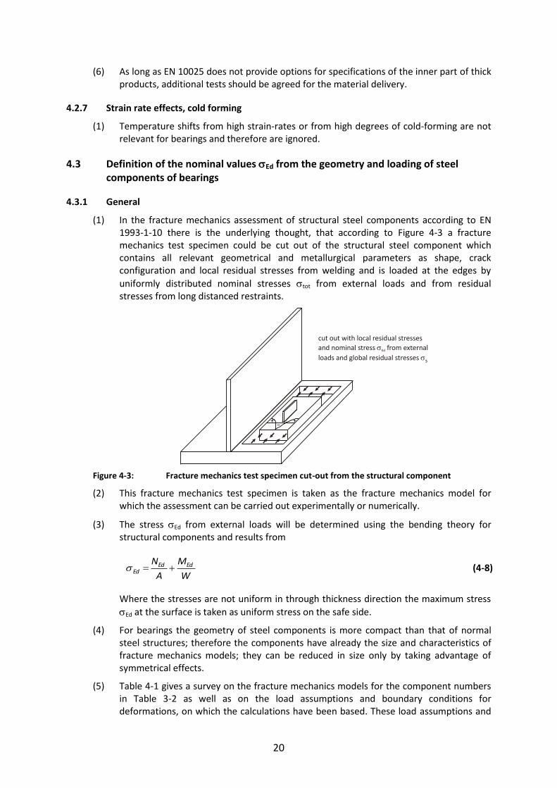
(1) In the fracture mechanics assessment of structural steel components according to EN 1993-1-10 there is the underlying thought, that according to Figure 4-3 a fracture mechanics test specimen could be cut out of the structural steel component which contains all relevant geometrical and metallurgical parameters as shape, crack configuration and local residual stresses from welding and is loaded at the edges by
uniformly distributed nominal stresses tot from external loads and from residual stresses from long distanced restraints.
Figure 4-3: Fracture mechanics test specimen cut-out from the structural component
(2) This fracture mechanics test specimen is taken as the fracture mechanics model for which the assessment can be carried out experimentally or numerically.
(3) The stress Ed from external loads will be determined using the bending theory for structural components and results from
W
M
A
N EdEdEd (4-8)
Where the stresses are not uniform in through thickness direction the maximum stress
Ed at the surface is taken as uniform stress on the safe side.
(4) For bearings the geometry of steel components is more compact than that of normal steel structures; therefore the components have already the size and characteristics of fracture mechanics models; they can be reduced in size only by taking advantage of symmetrical effects.
(5) Table 4-1 gives a survey on the fracture mechanics models for the component numbers in Table 3-2 as well as on the load assumptions and boundary conditions for deformations, on which the calculations have been based. These load assumptions and
cut out with local residual stresses
and nominal stress from external
loads and global residual stresses
Ed
s
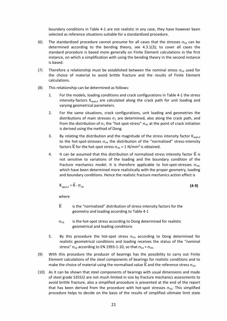
21
boundary conditions in Table 4-1 are not realistic in any case, they have however been selected as reference situations suitable for a standardized procedure.
(6) The standardized procedure cannot presume for all cases that the stresses Ed can be determined according to the bending theory, see 4.3.1(3); to cover all cases the standard procedure is based more generally on Finite Element calculations in the first instance, on which a simplification with using the bending theory in the second instance is based.
(7) Therefore a relationship must be established between the nominal stress Ed used for the choice of material to avoid brittle fracture and the results of Finite Element calculations.
(8) This relationship can be determined as follows:
1. For the models, loading conditions and crack configurations in Table 4-1 the stress intensity-factors Kappl,d are calculated along the crack path for unit loading and varying geometrical parameters.
2. For the same situations, crack configurations, unit loading and geometries the
distributions of main stresses 1 are determined, also along the crack path, and
from the distribution of 1 the “hot spot-stress” HS at the point of crack initiation is derived using the method of Dong.
3. By relating the distribution and the magnitude of the stress intensity factor Kappl,d
to the hot-spot-stresses HS the distribution of the “normalized” stress-intensity
factors for the hot-spot stress HS = 1 N/mm² is obtained.
4. It can be assumed that this distribution of normalized stress intensity factor is not sensitive to variations of the loading and the boundary condition of the
fracture mechanics model. It is therefore applicable to hot-spot-stresses HS, which have been determined more realistically with the proper geometry, loading and boundary conditions. Hence the realistic fracture mechanics action effect is
HSd,appl KK (4-9)
where
is the “normalized” distribution of stress-intensity factors for the geometry and loading according to Table 4-1
HS is the hot-spot stress according to Dong determined for realistic geometrical and loading conditions
5. By this procedure the hot-spot stress HS according to Dong determined for realistic geometrical conditions and loading receives the status of the “nominal
stress” Ed according to EN 1993-1-10, so that Ed = HS.
(9) With this procedure the producer of bearings has the possibility to carry out Finite Element calculations of the steel components of bearings for realistic conditions and to
make the choice of material using the normalised value and the reference stress Ed.
(10) As it can be shown that steel components of bearings with usual dimensions and made of steel grade S355J2 are not much limited in size by fracture mechanics assessments to avoid brittle fracture, also a simplified procedure is presented at the end of the report
that has been derived from the procedure with hot-spot stresses HS. This simplified procedure helps to decide on the basis of the results of simplified ultimate limit state

22
checks using the bending theory whether the usual dimensions are sufficient. This simplified procedure allows to avoid more complex Finite Element calculations.
Table 4-1: Fracture mechanics models with 2 dimension with assumptions for loading and boundary conditions
No. Component No. Component
1, 2A
1
3
1
2
2
2B
1
4
2
3
5
1
4
5
2
6
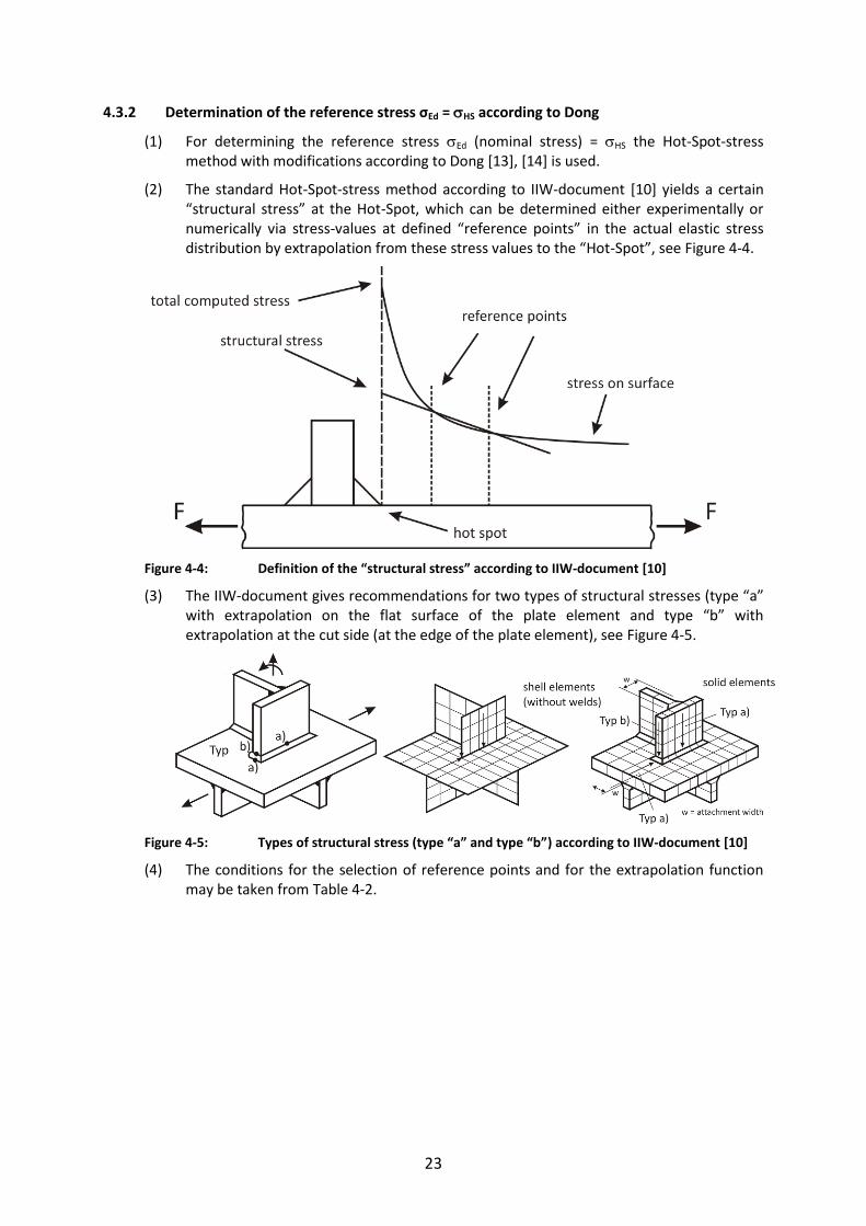
23
4.3.2 Determination of the reference stress σEd = HS according to Dong
(1) For determining the reference stress Ed (nominal stress) = HS the Hot-Spot-stress method with modifications according to Dong [13], [14] is used.
(2) The standard Hot-Spot-stress method according to IIW-document [10] yields a certain “structural stress” at the Hot-Spot, which can be determined either experimentally or numerically via stress-values at defined “reference points” in the actual elastic stress distribution by extrapolation from these stress values to the “Hot-Spot”, see Figure 4-4.
Figure 4-4: Definition of the “structural stress” according to IIW-document [10]
(3) The IIW-document gives recommendations for two types of structural stresses (type “a” with extrapolation on the flat surface of the plate element and type “b” with extrapolation at the cut side (at the edge of the plate element), see Figure 4-5.
Figure 4-5: Types of structural stress (type “a” and type “b”) according to IIW-document [10]
(4) The conditions for the selection of reference points and for the extrapolation function may be taken from Table 4-2.
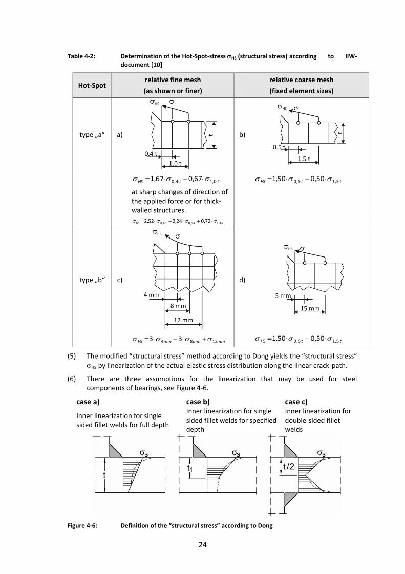
24
Table 4-2: Determination of the Hot-Spot-stress HS (structural stress) according to IIW-document [10]
Hot-Spot relative fine mesh
(as shown or finer)
relative coarse mesh
(fixed element sizes)
type „a“ a)
b)
ttHS 0,14,0 67,067,1 ttHS 5,15,0 50,050,1
at sharp changes of direction of the applied force or for thick-walled structures.
tttHS 4,19,04,0 72,024,252,2
type „b“ c)
d)
mmmmmmHS 1284 33 ttHS 5,15,0 50,050,1
(5) The modified “structural stress” method according to Dong yields the “structural stress”
HS by linearization of the actual elastic stress distribution along the linear crack-path.
(6) There are three assumptions for the linearization that may be used for steel components of bearings, see Figure 4-6.
case a) case b) case c)
Inner linearization for single sided fillet welds for full depth
Inner linearization for single sided fillet welds for specified depth
Inner linearization for double-sided fillet welds
Figure 4-6: Definition of the “structural stress” according to Dong

25
(7) The advantages of this method in relation to the standard method for determining the Hot-Spot-stresses are the following:
1. The structural stress HS determined in this way is from a single, linearization path and clear and unmistakable
2. It is taken into account that the structural stress HS is not only controlled by small cracks at the Hot-Spot, but also by larger cracks that have progressed into the
thickness of the product. Therefore HS represents a certain equivalent for the “total stress” perpendicular to the crack. This “total stress” is approximated by the linearization.
3. The method also has been calibrated to the results of fatigue tests with various geometries of detail.
4. The determination of the structural stress from FE-calculations is relatively insensitive on the Finite-element-net- chosen. The conditions to be applied for fine nets given in Table 4-2 are taken into account.
5. The method is specified for use for pressure vessels and pipelines in the ASME-standard [12].
(8) For the different cases of linearization in Figure 4-6 the following applies:
- case a): monotonous reduction of the actual elastic stress distribution (dotted line) across the section; the “inner” linearization comprises the full cross-section. This results in general in the stresses as determined from the bending theory.
- case b): monotonous reduction of the actual elastic stress distribution (dotted line) in thick or wide cross-section or plates; the “inner” linearization is then recommended to cover only a part of the thick cross-section with a depth t1 < t. It applies e.g. for cracks starting from a notch at the surface. For bearings the depth t1 was determined at that point, where the actual elastic stress is reduced to 10 % of its maximum value.
- case c): non-monotonous reduction of the actual elastic stress distribution across the depth of the cross-section, e.g. for thick plates with welded attachments at either sides.
This leads to a bilinear inner linearization.
For welded connections on both sides of the plate and for symmetrical stress distribution the linearization is recommended to be applied over half the plate thickness (t1 = t/2). This gives a supplementary definition of structural stress used by Dong which is applicable for monotonous reduction of stress only.
4.3.3 Example for the determination of structural stress according to Dong
(1) As an example for the determination of the structural stress according to Dong the detail 2A from Figure 4-1 is chosen, for which the dimensions according to Figure 4-7 are applied.
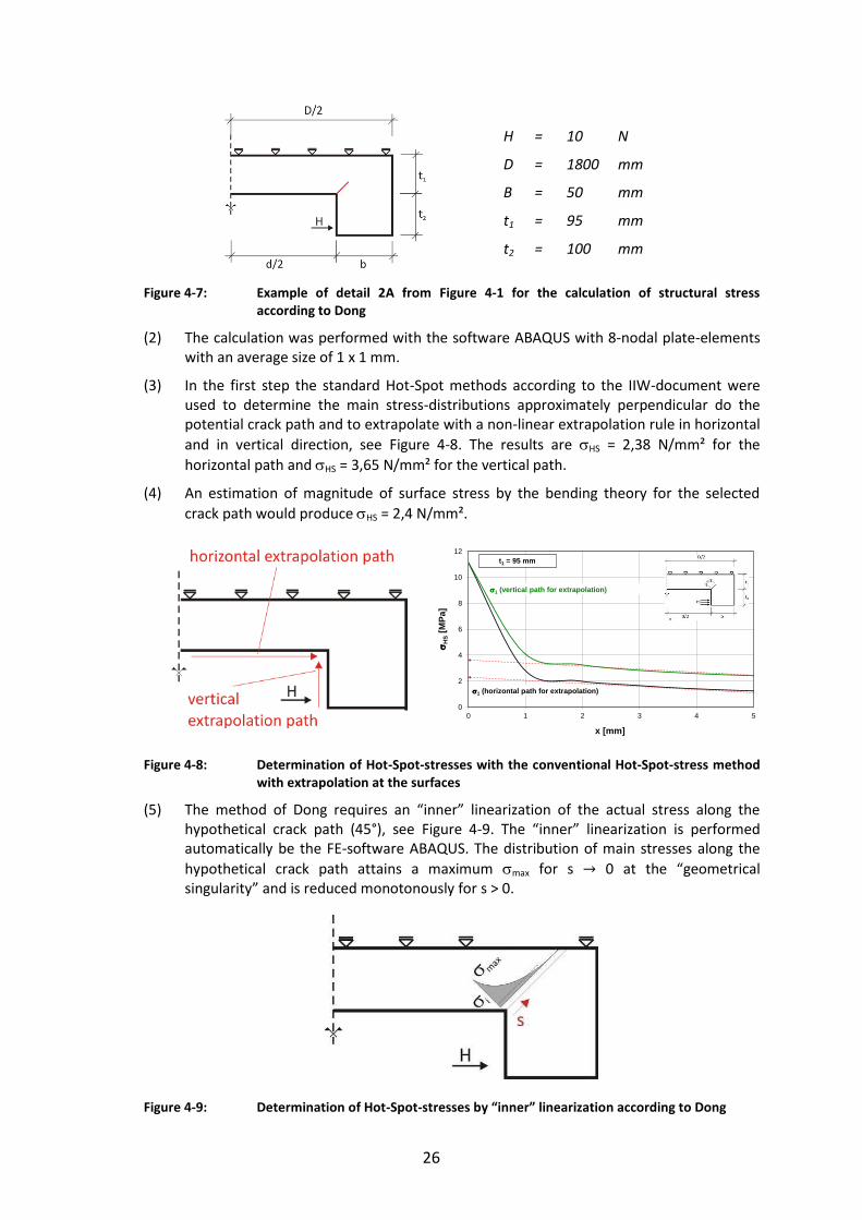
26
H
D
B
t1
t2
=
=
=
=
=
10
1800
50
95
100
N
mm
mm
mm
mm
Figure 4-7: Example of detail 2A from Figure 4-1 for the calculation of structural stress according to Dong
(2) The calculation was performed with the software ABAQUS with 8-nodal plate-elements with an average size of 1 x 1 mm.
(3) In the first step the standard Hot-Spot methods according to the IIW-document were used to determine the main stress-distributions approximately perpendicular do the potential crack path and to extrapolate with a non-linear extrapolation rule in horizontal
and in vertical direction, see Figure 4-8. The results are HS = 2,38 N/mm² for the
horizontal path and HS = 3,65 N/mm² for the vertical path.
(4) An estimation of magnitude of surface stress by the bending theory for the selected
crack path would produce HS = 2,4 N/mm².
Figure 4-8: Determination of Hot-Spot-stresses with the conventional Hot-Spot-stress method with extrapolation at the surfaces
(5) The method of Dong requires an “inner” linearization of the actual stress along the hypothetical crack path (45°), see Figure 4-9. The “inner” linearization is performed automatically be the FE-software ABAQUS. The distribution of main stresses along the
hypothetical crack path attains a maximum max for s 0 at the “geometrical singularity” and is reduced monotonously for s > 0.
Figure 4-9: Determination of Hot-Spot-stresses by “inner” linearization according to Dong
0
2
4
6
8
10
12
0 1 2 3 4 5
H
S[M
Pa]
x [mm]
1 (vertical path for extrapolation)
1 (horizontal path for extrapolation)
t1 = 95 mm

27
(6) It is evident, that the magnitudes of the Hot-Spot-stresses are dependent on the length s
used for the linearization. This length s is limited by the threshold value i, under which stresses are ignored.
(7) In Figure 4-10 the Hot-Spot-stresses are plotted versus the linearization length and the
related threshold stress i:
For I > 1.0 N/mm² the value HS is HS = 4,05 N/mm², for 1 = 0,5 N/mm² the value HS
is HS = 3,33 N/mm².
a)
b)
Figure 4-10: Determination of the Hot-Spot-stress by the “inner” linearization according to
Dong (a) and comparison with conventional Hot-Spot-stresses obtained by surface extrapolation (b) according to Figure 4-8
(8) Figure 4-10 and Table 4-3 also show a comparison of results obtained with the conventional surface extrapolation method.
Table 4-3: Comparison of Hot-Spot-stresses for the detail 2A
bending theory
Hot-Spot-method
extrapolation inner linearization
horizontal vertical i > 0,0 MPa i > 0,5 MPa i > 1,0 MPa
HS
[MPa] 2,4 2,38 3,65 1,92 3,33 4,05
0,0
2,0
4,0
6,0
8,0
10,0
12,0
0,0
1,0
2,0
3,0
4,0
5,0
6,0
0 10 20 30 40 50 60 70
Prin
cipa
l str
ess
1[M
Pa]
H
S[M
Pa]
s [mm]
linearized stresses
Principal stresses
i > 0,5 N/mm²i > 1,0 N/mm²
t1 = 95 mm
0
2
4
6
8
10
12
0 1 2 3 4 5
H
S[M
Pa]
x [mm]
i > 1,0 N/mm²i > 0,5 N/mm²
i > 0,0 N/mm²
1 (vertical path for extrapolation)
1 (horizontal path for extrapolation) analytical
t1 = 95 mm

28
(9) The comparison of results shows that the surface extrapolation gives only for the vertical extrapolation path representative values for fracture mechanics assessments. The “inner” linearization according to Dong gives only representative results for the
threshold value i > 1,0 N/mm² .
(10) From various such comparisons the conclusion has been drawn that for the method of Dong the threshold value should be fixed with the relative value
I = 0.10 max, see Figure 4-11.
(11) The results of “inner” linearization with this threshold value I = 0.10 max and of the extrapolation with the vertical surface extrapolation are given in Figure 4-11 as a function of the product thickness t.
Figure 4-11: Hot-Spot-stresses from “inner” linearization according to Dong for the threshold
value I 0.10 max, (10 % criterion) and comparison with the results of surface extrapolation
(12) The dependency of the Hot-Spot stresses from the product thickness is affine for all methods.
(13) In the following report therefore the method of inner linearization according to Dong is applied.
(14) In this application the following steps were carried out:
1. Determination of the potential crack path to fix the linearization-path
2. Determination of main stress along the linearization path and derivation of the tensile stress-component perpendicular to the crack path
3. Determination of the length of linearization from the distribution of the maximum tensile stresses (10 % criterion)
4. Performance of the linearization
5. Derivation of the Hot-Spot-stress HS.
Note: When preparing the meshing for Finite-Element-calculations it is necessary to provide a suitable radius at the point of “singularity”. Unless other data are available, a radius of 1 mm should be applied.
0,0
4,0
8,0
12,0
2,0
2,5
3,0
3,5
4,0
4,5
5,0
5,5
6,0
0 50 100 150 200 250
max
1
[MPa
]
H
S[M
Pa]
t1 [mm]
linearization of stresses
numrical value of stresses at hot-spot
from extrapolation on vertical path

29
5 Numerical investigations and results
5.1 General
(1) For the models given in Table 3-2 and Table 4-1 the numerical investigations were performed with the FE-Software ABAQUS, Version 6.8, to obtain
- the Hot-spot-stresses according to section 4.3 of this report
- the stress intensity factor K,
as no catalogues of solutions were available for these details.
(2) The calculations were carried out with a linear elastic material law.
(3) The calculations gave the distributions the stress intensity factors K at the crack front.
(4) Out-puts of the calculations were the K-values for the crack-opening modes K1 and K2, see Figure 5-1.
Mode 1 (Opening) Mode 2 (Shearing) Mode 3 (Tearing)
Figure 5-1: Crack opening modes
(5) The assessment method assumes that the main stresses are actions for crack opening mode 1.
(6) In order to cover the fact that the main stresses may possibly not be perpendicular to the crack-path, an effective Keff is determined
2221
21 KKKKKeff (5-1)
(7) The fracture mechanics assessment is carried out with the maximum stress-intensity factor
eff1 K,KmaxK (5-2)
(8) For simplicity reasons the investigations are performed with a unit line load resulting
from = 1 N/mm for a section with a length of 10 mm (load introduction). Due to linear relationship a different scaling of stresses, strains or stress intensity factors is easily possible.

30
(9) As a rule two calculations are carried out, one with the maximum, one with the minimum dimensions, that shall clarify, what gives the maximum influence on the risk of brittle fracture. In this report therefore fracture mechanics assessments were performed for the upper bounds and the lower bounds of the geometry of the bearings.
(10) Calculation models were produced using symmetries to reduce the expenditure for modelling and calculation.
(11) The modelling was made with two dimensional plate elements (8 nodal elements). In particular for the modelling of the crack tip a very fine meshing was necessary.
(12) In addition the determination of the stress intensity factor at the crack tip requires a particular meshing of this region with special-collapsed crack tip elements, that take account of the stress singularity at that spot, see Figure 5-2 for the example of the geometry of the detail 1 according to Table 4-1.
Figure 5-2: Spider web mesh configuration at the crack tip with collapsed finite elements for detail 1 in Table 4-1

31
5.2 Component No 1 – Rotationally-symmetric top component, type A (sliding plate and lateral guiderail)
5.2.1 Geometry, load assumptions and boundary conditions
(1) The geometry of the top component is given in Figure 5-3.
Figure 5-3: Detail No 1 – Top component of type A (sliding plate and guiderail)
(2) The numerical values of dimensions may be taken from Table 5-1.
Table 5-1: Dimensions for detail 1
t [mm] t1 [mm] t2 [mm] D [mm] d [mm] b [mm]
55 – 315 20 – 215 25 – 100 500 – 1800 355 – 1385 50 - 500
(3) The loading should be independent of individual situations with realistic loading conditions. Therefore standard loading cases have been chosen that lead to representative fracture mechanics loading, see variants 1-1 and 1-2 in Figure 5-4.
(4) Both variants for loading lead to tension stresses in the re-entrant corner at the connection between the sliding plate and the guiderail.
Loading variant 1-1 Loading variant 1-2
Figure 5-4: Variants for loading for detail 1: Variant 1 with horizontal loading (left), variant 2 with vertical loading (right)
(5) The calculations were performed for two geometrical configurations at the lower and upper bounds of dimensions as recommended by the producers of bearings, see Table 5-2. Besides the plate-thickness t1 also the width b of the guide-rail has proved to be relevant for the variation of the stress intensity factors. The diameter D of the sliding plate was kept maximum, to produce the maximum bending moment in particular for loading variant 2 at the re-entrant corner.
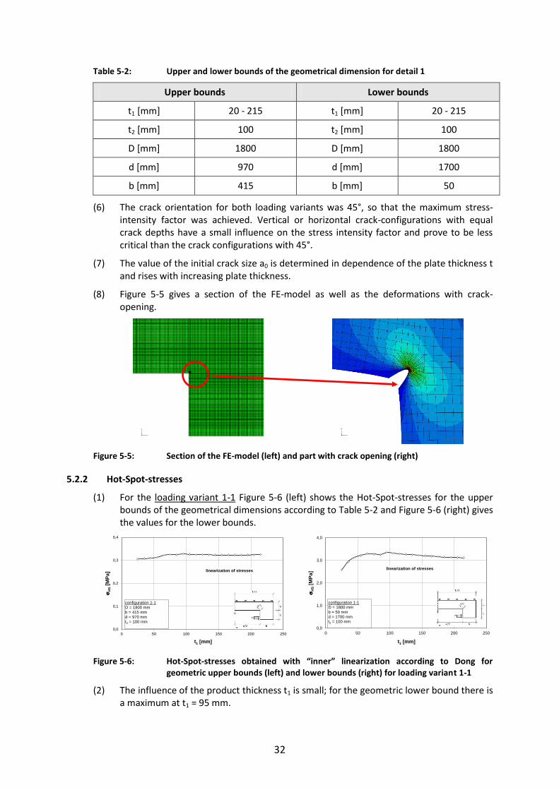
32
Table 5-2: Upper and lower bounds of the geometrical dimension for detail 1
Upper bounds Lower bounds
t1 [mm] 20 - 215 t1 [mm] 20 - 215
t2 [mm] 100 t2 [mm] 100
D [mm] 1800 D [mm] 1800
d [mm] 970 d [mm] 1700
b [mm] 415 b [mm] 50
(6) The crack orientation for both loading variants was 45°, so that the maximum stress-intensity factor was achieved. Vertical or horizontal crack-configurations with equal crack depths have a small influence on the stress intensity factor and prove to be less critical than the crack configurations with 45°.
(7) The value of the initial crack size a0 is determined in dependence of the plate thickness t and rises with increasing plate thickness.
(8) Figure 5-5 gives a section of the FE-model as well as the deformations with crack-opening.
Figure 5-5: Section of the FE-model (left) and part with crack opening (right)
5.2.2 Hot-Spot-stresses
(1) For the loading variant 1-1 Figure 5-6 (left) shows the Hot-Spot-stresses for the upper bounds of the geometrical dimensions according to Table 5-2 and Figure 5-6 (right) gives the values for the lower bounds.
Figure 5-6: Hot-Spot-stresses obtained with “inner” linearization according to Dong for geometric upper bounds (left) and lower bounds (right) for loading variant 1-1
(2) The influence of the product thickness t1 is small; for the geometric lower bound there is a maximum at t1 = 95 mm.
0,0
0,1
0,2
0,3
0,4
0 50 100 150 200 250
H
S[M
Pa]
t1 [mm]
linearization of stresses
configuration 1-1 D = 1800 mm b = 415 mm d = 970 mmt2 = 100 mm
0,0
1,0
2,0
3,0
4,0
0 50 100 150 200 250
H
S[M
Pa]
t1 [mm]
linearization of stresses
configuration 1-1 D = 1800 mm b = 50 mm d = 1700 mmt2 = 100 mm
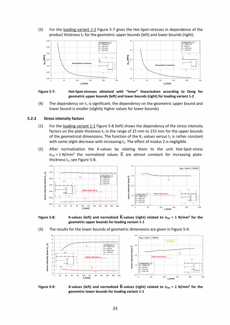
33
(3) For the loading variant 1-2 Figure 5-7 gives the Hot-Spot-stresses in dependence of the product thickness t1 for the geometric upper bounds (left) and lower bounds (right).
Figure 5-7: Hot-Spot-stresses obtained with “inner” linearization according to Dong for geometric upper bounds (left) and lower bounds (right) for loading variant 1-2
(4) The dependency on t1 is significant; the dependency on the geometric upper bound and lower bound is smaller (slightly higher values for lower bounds)
5.2.3 Stress intensity factors
(1) For the loading variant 1-1 Figure 5-8 (left) shows the dependency of the stress intensity factors on the plate thickness t1 in the range of 25 mm to 215 mm for the upper bounds of the geometrical dimensions. The function of the K1 values versus t1 is rather constant with some slight decrease with increasing t1. The effect of modus 2 is negligible.
(2) After normalization the K-values by relating them to the unit Hot-Spot-stress
HS = 1 N/mm² the normalized values are almost constant for increasing plate-thickness t1, see Figure 5-8.
Figure 5-8: K-values (left) and normalized -values (right) related to HS = 1 N/mm² for the geometric upper bounds for loading variant 1-1
(3) The results for the lower bounds of geometric dimensions are given in Figure 5-9.
Figure 5-9: K-values (left) and normalized -values (right) related to HS = 1 N/mm² for the geometric lower bounds for loading variant 1-1
0,00
0,05
0,10
0,15
0,20
0,25
0,30
0 50 100 150 200 250
H
S[M
Pa]
t1 [mm]
linearization of stresses
configuration 1-2 D = 1800 mm b = 415 mm d = 970 mmt2 = 100 mm
0,0
0,1
0,2
0,3
0,4
0 50 100 150 200 250
H
S[M
Pa]
t1 [mm]
linearization of stresses
configuration 1-2 D = 1800 mm b = 50 mm d = 1700 mmt2 = 100 mm
0,00
0,20
0,40
0,60
0,80
1,00
1,20
0 20 40 60 80 100 120 140 160 180 200 220
stre
ss in
tens
ity fa
ctor
K1,
K2
t1 [mm]
configuration 1-1D = 1800 mm b = 415 mm d = 970 mmt2 = 100 mm
initial crack size a0
K1
K2
0,0
1,0
2,0
3,0
4,0
0 50 100 150 200 250
stre
ss in
tens
itry
fact
or K
t1 [mm]
initial crack size a0
HS = const. = 1 N/mm
configuration 1-1 D = 1800 mm b = 415 mm d = 970 mmt2 = 100 mm
K1
0
1
2
3
4
5
6
7
8
9
10
0 20 40 60 80 100 120 140 160 180 200 220
stre
ss in
tens
ity fa
ctor
K1,
K2
t1 [mm]
configuration 1-1D = 1800 mm b = 55 mm d = 1690 mmt2 = 100 mm
initial crack size a0
K1
K2
K = 2,3031e0,0007t
R2 = 0,9709
0,0
1,0
2,0
3,0
4,0
0 50 100 150 200 250
stre
ss in
tens
ity fa
ctor
K
t1 [mm]
initial crack size a0
HS = const. = 1 N/mm
configuration 1-2D = 1800 mm b = 50 mm d = 970 mmt2 = 100 mm
K1

34
(4) Whereas in Figure 5-9 (left) the K-values decrease for t < 100 mm, the normalized
-values related to HS = 1 N/mm² (Figure 5-9, right) are linear and can be approximated by
= 10007,03021,2
te
(5-3)
(5) For loading variant 1-2 Figure 5-10 gives the dependency of the K-values on the product thickness t1 for the geometrical upper bounds of the dimensions.
Figure 5-10: K-values (left) and normalized -values (right) related to HS = 1 N/mm² for the geometric upper bounds of dimensions for loading variant 1-2
(6) After normalising the K-values by relating them to HS = 1 N/mm² the normalized -values can be approximated by the polynomial
= 1188,2107547,1102514,1100779,3 122
143
17 ttt (5-4)
(7) In Figure 5-11 similar values are shown for the lower bounds of the geometrical dimensions.
Figure 5-11: K-values (left) and normalized -values (right) related to HS = 1 N/mm² for the geometric lower bounds of dimensions for loading variant 1-2
(8) After normalizing the K-values by relating them to HS = 1 N/mm² the normalized -values can be approximated by the polynomial
= 1674,2100121,1105274,7109297,1 122
153
17 ttt (5-5)
5.2.4 Assessments to avoid brittle fracture
(1) The fracture mechanics assessment was performed for steel S355J2 for
- varying product thicknesses t1,
- varying utilisation rates
and
- temperatures TEd of the components
-0,2
-0,1
0,0
0,1
0,2
0,3
0,4
0,5
0,6
0,7
0,8
0 20 40 60 80 100 120 140 160 180 200 220stre
ss in
tens
ity fa
ctor
K1,
K2
t1 [mm]
configuration 1-2D = 1800 mm b = 415 mmd = 970 mmt2 = 100 mm
initial crack size a0
K1
K2
K = 3∙10-7∙t13 - 0,0001∙t1
2 + 0,0175∙t1 + 2,1188R2 = 0,9855
0
1
2
3
4
0 50 100 150 200 250
stre
ss in
tens
ity fa
ctor
K
t1 [mm]
configuration 1-2 D = 1800 mm b = 415 mm d = 970 mmt2 = 100 mm
initial crack size a0
K1
HS = const. = 1 N/mm
-0,2
-0,1
0,0
0,1
0,2
0,3
0,4
0,5
0,6
0,7
0,8
0 20 40 60 80 100 120 140 160 180 200 220stre
ss in
tens
ity fa
ctor
K1,
K2
t1 [mm]
configuration 1-2D = 1800 mm b = 50 mm d = 1690 mmt2 = 100 mm
initial crack size a0
K1
K2
K = 2∙10-7t13 - 8∙10-5t1
2 + 0,0101t1 + 2,1674R2 = 0,8402
0
1
2
3
4
0 50 100 150 200 250
stre
s in
tens
ity fa
ctor
K
t1 [mm]
initial crack size a0
configuration 1-2D = 1800 mm b = 50 mm d = 970 mmt2 = 100 mm
K1
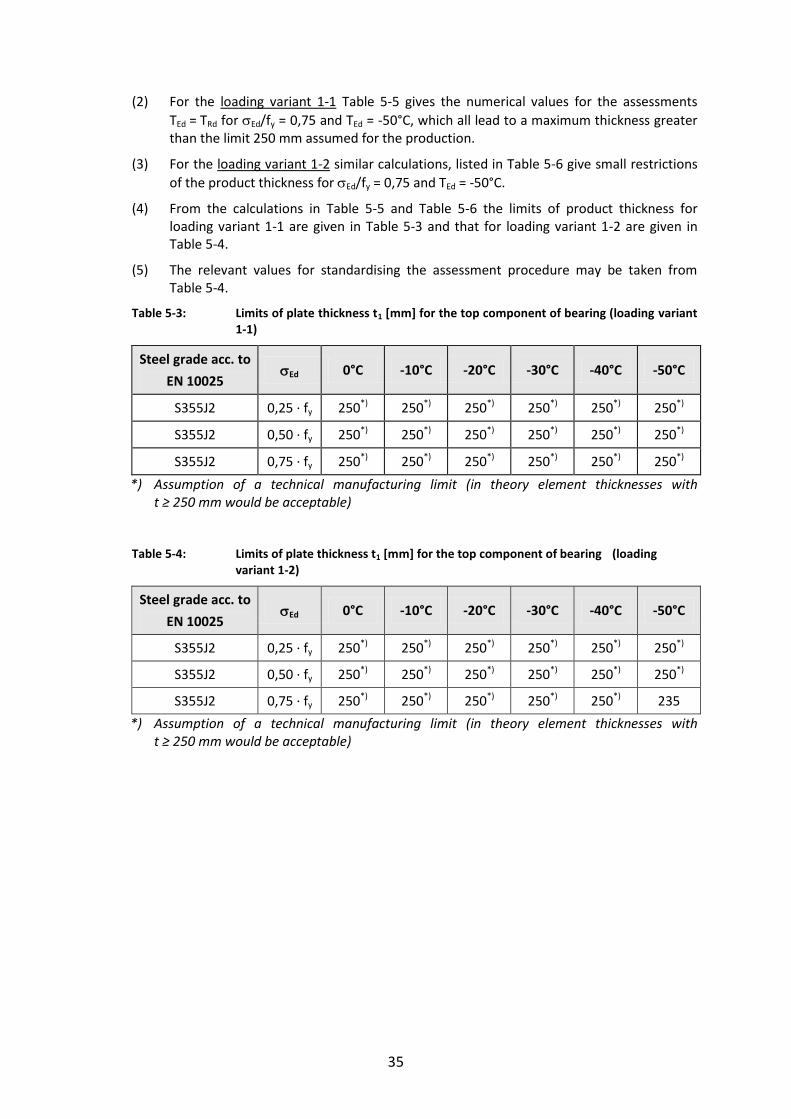
35
(2) For the loading variant 1-1 Table 5-5 gives the numerical values for the assessments
TEd = TRd for Ed/fy = 0,75 and TEd = -50°C, which all lead to a maximum thickness greater than the limit 250 mm assumed for the production.
(3) For the loading variant 1-2 similar calculations, listed in Table 5-6 give small restrictions
of the product thickness for Ed/fy = 0,75 and TEd = -50°C.
(4) From the calculations in Table 5-5 and Table 5-6 the limits of product thickness for loading variant 1-1 are given in Table 5-3 and that for loading variant 1-2 are given in Table 5-4.
(5) The relevant values for standardising the assessment procedure may be taken from Table 5-4.
Table 5-3: Limits of plate thickness t1 [mm] for the top component of bearing (loading variant 1-1)
Steel grade acc. to
EN 10025 Ed 0°C -10°C -20°C -30°C -40°C -50°C
S355J2 0,25 ∙ fy 250*) 250*) 250*) 250*) 250*) 250*)
S355J2 0,50 ∙ fy 250*) 250*) 250*) 250*) 250*) 250*)
S355J2 0,75 ∙ fy 250*) 250*) 250*) 250*) 250*) 250*)
*) Assumption of a technical manufacturing limit (in theory element thicknesses with t ≥ 250 mm would be acceptable)
Table 5-4: Limits of plate thickness t1 [mm] for the top component of bearing (loading variant 1-2)
Steel grade acc. to
EN 10025 Ed 0°C -10°C -20°C -30°C -40°C -50°C
S355J2 0,25 ∙ fy 250*) 250*) 250*) 250*) 250*) 250*)
S355J2 0,50 ∙ fy 250*) 250*) 250*) 250*) 250*) 250*)
S355J2 0,75 ∙ fy 250*) 250*) 250*) 250*) 250*) 235
*) Assumption of a technical manufacturing limit (in theory element thicknesses with t ≥ 250 mm would be acceptable)

36
Table 5-5: Fracture mechanics assessments for loading variant 1-1 for component No. 1 (Rotationally-symmetric top component (Sliding plate and guiderail))
Ass
essm
ent
for
Ed =
0,7
5∙f
y a
nd
T =
-50
°C
Nr
P
K1
Ed
/f y
P
Sa 0
t 1K
1,P
K1,
SK
1,ge
sK
1,ge
sf y,
nom
f y(t)
gy
L r
1
k R
6K
appl
,d
Kap
pl,d
b e
ff
T
KV,
nom
T KV
T 27J
T 2
7J
T R
T md
T r
T
T DC
FT E
dT R
d
N/m
m²
N/m
m3/
2[-]
N/m
m²
N/m
m²
mm
mm
N/m
m3/
2N
/mm
3/2
N/m
m3/
2M
Pam
1/2
N/m
m²
N/m
m²
N/m
m²
- -
- -
-N
/mm
3/2
MPa
m1/
2m
m°C
J°C
°C°C
°C°C
°C°C
°C°C
°C1
1,0
3,17
0,75
266,
310
01,
6125
845
317
1163
36,8
355
349
326
0,82
0,31
0,04
0,04
0,87
1407
44,5
2514
,49
81,9
27-2
0-2
05
7-4
5-5
00
39-3
32
1,0
3,21
0,75
266,
310
01,
7835
855
321
1176
37,2
355
346
329
0,81
0,30
0,04
0,04
0,87
1421
44,9
3517
,13
73,2
27-2
0-2
012
7-4
5-5
00
30-2
63
1,0
3,21
0,75
266,
310
01,
9045
856
321
1177
37,2
355
344
329
0,81
0,30
0,04
0,04
0,87
1422
45,0
4518
,93
68,0
27-2
0-2
019
7-4
5-5
00
25-1
94
1,0
3,17
0,75
266,
310
02,
0055
845
317
1162
36,7
355
341
329
0,81
0,30
0,04
0,04
0,87
1405
44,4
5519
,74
65,8
27-2
0-2
022
7-4
5-5
00
23-1
65
1,0
3,08
0,75
266,
310
02,
0965
821
308
1129
35,7
355
339
328
0,81
0,30
0,04
0,04
0,87
1365
43,2
6519
,41
66,7
27-2
0-2
024
7-4
5-5
00
24-1
46
1,0
3,04
0,75
266,
310
02,
1675
809
304
1113
35,2
355
336
327
0,82
0,31
0,04
0,04
0,87
1347
42,6
7519
,73
65,9
27-2
0-2
025
7-4
5-5
00
23-1
37
1,0
3,04
0,75
266,
310
02,
2285
809
304
1113
35,2
355
334
325
0,82
0,31
0,04
0,04
0,87
1347
42,6
8520
,68
63,4
27-2
0-2
025
7-4
5-5
00
20-1
38
1,0
2,99
0,75
266,
310
02,
2895
796
299
1095
34,6
355
331
323
0,82
0,31
0,04
0,04
0,86
1327
42,0
9520
,66
63,4
27-2
0-2
025
7-4
5-5
00
20-1
39
1,0
2,99
0,75
266,
310
02,
3310
579
629
910
9634
,635
532
932
10,
830,
310,
040,
040,
8613
2842
,010
521
,49
61,4
27-2
0-2
025
7-4
5-5
00
18-1
310
1,0
2,99
0,75
266,
310
02,
3711
579
629
910
9634
,635
532
632
00,
830,
310,
040,
040,
8613
2942
,011
522
,26
59,6
27-2
0-2
026
7-4
5-5
00
17-1
211
1,0
2,99
0,75
266,
310
02,
4112
579
729
910
9634
,735
532
431
70,
840,
310,
040,
040,
8613
3142
,112
523
,02
57,8
27-2
0-2
026
7-4
5-5
00
15-1
212
1,0
2,99
0,75
266,
310
02,
4513
579
729
910
9634
,735
532
131
50,
840,
320,
040,
040,
8613
3242
,113
523
,71
56,3
27-2
0-2
026
7-4
5-5
00
13-1
213
1,0
2,99
0,75
266,
310
02,
4914
579
729
910
9634
,735
531
931
30,
850,
320,
040,
030,
8613
3342
,114
524
,37
54,9
27-2
0-2
026
7-4
5-5
00
12-1
214
1,0
2,99
0,75
266,
310
02,
5215
579
729
910
9634
,735
531
631
10,
860,
320,
040,
030,
8613
3442
,215
525
,01
53,5
27-2
0-2
026
7-4
5-5
00
11-1
215
1,0
2,99
0,75
266,
310
02,
5516
579
729
910
9634
,735
531
430
90,
860,
320,
040,
030,
8513
3642
,216
525
,64
52,2
27-2
0-2
026
7-4
5-5
00
9-1
216
1,0
2,99
0,75
266,
310
02,
5817
579
729
910
9734
,735
531
130
70,
870,
330,
040,
030,
8513
3742
,317
526
,24
51,0
27-2
0-2
026
7-4
5-5
00
8-1
217
1,0
3,00
0,75
266,
310
02,
6118
579
830
010
9734
,735
530
930
40,
870,
330,
040,
030,
8513
3942
,318
526
,85
49,8
27-2
0-2
026
7-4
5-5
00
7-1
218
1,0
3,00
0,75
266,
310
02,
6419
579
830
010
9734
,735
530
630
20,
880,
330,
040,
030,
8513
4142
,419
527
,43
48,7
27-2
0-2
026
7-4
5-5
00
6-1
219
1,0
3,00
0,75
266,
310
02,
6620
579
830
010
9834
,735
530
430
00,
890,
330,
040,
030,
8513
4342
,520
528
,00
47,7
27-2
0-2
026
7-4
5-5
00
5-1
220
1,0
3,00
0,75
266,
310
02,
6921
579
930
010
9834
,735
530
129
70,
890,
340,
050,
030,
8513
4442
,521
528
,56
46,6
27-2
0-2
026
7-4
5-5
00
4-1
221
1,0
3,00
0,75
266,
310
02,
7122
579
930
010
9834
,735
529
929
50,
900,
340,
050,
030,
8413
4642
,622
529
,07
45,7
27-2
0-2
026
7-4
5-5
00
3-1
222
1,0
3,00
0,75
266,
310
02,
7323
579
930
010
9834
,735
529
629
30,
910,
340,
050,
030,
8413
4742
,623
529
,57
44,8
27-2
0-2
026
7-4
5-5
00
2-1
223
1,0
3,00
0,75
266,
310
02,
7524
579
930
010
9834
,735
529
429
00,
920,
340,
050,
020,
8413
4842
,624
530
,06
44,0
27-2
0-2
026
7-4
5-5
00
1-1
223
1,0
3,00
0,75
266,
310
02,
7625
079
930
010
9834
,735
529
328
90,
920,
350,
050,
020,
8413
4942
,725
030
,30
43,6
27-2
0-2
026
7-4
5-5
00
1-1
2no
risk
no ri
skno
risk
no ri
skno
risk
no ri
skno
risk
no ri
skno
risk
no ri
sk
no ri
sk
T Ed
≥ T
Rd
no ri
skno
risk
no ri
sk
no ri
skno
risk
no ri
skno
risk
no ri
sk
no ri
skno
risk
no ri
skno
risk
no ri
sk

37
Table 5-6: Fracture mechanics assessments for loading variant 1-2 for component No. 1 (Rotationally-symmetric top component (Sliding plate and guiderail))
Ass
essm
ent
for
Ed =
0,7
5∙f
y a
nd
T =
-40
°C
Ass
essm
ent
for
Ed =
0,7
5∙f
y a
nd
T =
-50
°C
Nr
P
K1
Ed
/f y
P
Sa 0
t 1K
1,P
K1,
SK
1,ge
sK
1,ge
sf y,
nom
f y(t)
gy
L r
1
k R
6K
appl
,d
Kap
pl,d
b e
ff
T
KV,
nom
T KV
T 27J
T 2
7J
T R
T md
T r
T
T DC
FT E
dT R
d
N/m
m²
N/m
m3/
2[-]
N/m
m²
N/m
m²
mm
mm
N/m
m3/
2N
/mm
3/2
N/m
m3/
2M
Pam
1/2
N/m
m²
N/m
m²
N/m
m²
- -
- -
-N
/mm
3/2
MPa
m1/
2m
m°C
J°C
°C°C
°C°C
°C°C
°C°C
°C1
1,0
2,48
10,
7526
6,3
100
1,61
2566
124
890
928
,735
534
932
60,
820,
310,
040,
040,
8710
9934
,825
120,
027
-20
-20
57
-35
-50
087
-33
21,
02,
575
0,75
266,
310
01,
7835
686
257
943
29,8
355
346
329
0,81
0,30
0,04
0,04
0,87
1140
36,0
3511
6,5
27-2
0-2
012
7-3
5-5
00
83-2
63
1,0
2,68
50,
7526
6,3
100
1,90
4571
526
998
331
,135
534
432
90,
810,
300,
040,
040,
8711
8837
,645
99,3
27-2
0-2
019
7-3
5-5
00
66-1
94
1,0
2,78
80,
7526
6,3
100
2,00
5574
227
910
2132
,335
534
132
90,
810,
300,
040,
040,
8712
3439
,055
86,8
27-2
0-2
022
7-3
5-5
00
54-1
65
1,0
2,79
70,
7526
6,3
100
2,09
6574
528
010
2532
,435
533
932
80,
810,
300,
040,
040,
8712
3939
,265
82,4
27-2
0-2
024
7-3
5-5
00
49-1
46
1,0
2,89
10,
7526
6,3
100
2,16
7577
028
910
5933
,535
533
632
70,
820,
310,
040,
040,
8712
8140
,575
73,6
27-2
0-2
025
7-3
5-5
00
41-1
37
1,0
2,90
00,
7526
6,3
100
2,22
8577
229
010
6233
,635
533
432
50,
820,
310,
040,
040,
8712
8640
,785
70,5
27-2
0-2
025
7-3
5-5
00
37-1
38
1,0
2,91
20,
7526
6,3
100
2,28
9577
529
110
6633
,735
533
132
30,
820,
310,
040,
040,
8612
9240
,895
67,5
27-2
0-2
025
7-3
5-5
00
35-1
39
1,0
2,92
40,
7526
6,3
100
2,33
105
779
292
1071
33,9
355
329
321
0,83
0,31
0,04
0,04
0,86
1298
41,1
105
64,8
27-2
0-2
025
7-3
5-5
00
32-1
310
1,0
2,93
60,
7526
6,3
100
2,37
115
782
294
1075
34,0
355
326
320
0,83
0,31
0,04
0,04
0,86
1305
41,3
115
62,3
27-2
0-2
026
7-3
5-5
00
29-1
211
1,0
2,95
00,
7526
6,3
100
2,41
125
786
295
1081
34,2
355
324
317
0,84
0,31
0,04
0,04
0,86
1312
41,5
125
59,9
27-2
0-2
026
7-3
5-5
00
27-1
212
1,0
2,96
10,
7526
6,3
100
2,45
135
788
296
1085
34,3
355
321
315
0,84
0,32
0,04
0,04
0,86
1318
41,7
135
57,8
27-2
0-2
026
7-3
5-5
00
25-1
213
1,0
2,97
10,
7526
6,3
100
2,49
145
791
297
1088
34,4
355
319
313
0,85
0,32
0,04
0,03
0,86
1323
41,9
145
55,9
27-2
0-2
026
7-3
5-5
00
23-1
214
1,0
2,98
20,
7526
6,3
100
2,52
155
794
298
1092
34,5
355
316
311
0,86
0,32
0,04
0,03
0,86
1329
42,0
155
54,0
27-2
0-2
026
7-3
5-5
00
21-1
215
1,0
2,99
20,
7526
6,3
100
2,55
165
797
299
1096
34,7
355
314
309
0,86
0,32
0,04
0,03
0,85
1335
42,2
165
52,3
27-2
0-2
026
7-3
5-5
00
19-1
216
1,0
3,00
10,
7526
6,3
100
2,58
175
799
300
1099
34,8
355
311
307
0,87
0,33
0,04
0,03
0,85
1340
42,4
175
50,7
27-2
0-2
026
7-3
5-5
00
18-1
217
1,0
3,00
90,
7526
6,3
100
2,61
185
801
301
1102
34,8
355
309
304
0,87
0,33
0,04
0,03
0,85
1345
42,5
185
49,2
27-2
0-2
026
7-3
5-5
00
16-1
218
1,0
3,11
70,
7526
6,3
100
2,64
195
830
312
1142
36,1
355
306
302
0,88
0,33
0,04
0,03
0,85
1395
44,1
195
43,6
27-2
0-2
026
7-3
5-5
00
11-1
219
1,0
3,12
50,
7526
6,3
100
2,66
205
832
313
1145
36,2
355
304
300
0,89
0,33
0,04
0,03
0,85
1400
44,3
205
42,3
27-2
0-2
026
7-3
5-5
00
9-1
220
1,0
3,13
00,
7526
6,3
100
2,69
215
833
313
1147
36,3
355
301
297
0,89
0,34
0,05
0,03
0,85
1403
44,4
215
41,1
27-2
0-2
026
7-3
5-5
00
8-1
221
1,0
3,23
80,
7526
6,3
100
2,71
225
862
324
1186
37,5
355
299
295
0,90
0,34
0,05
0,03
0,84
1453
45,9
225
36,2
27-2
0-2
026
7-3
5-5
00
3-1
222
1,0
3,32
60,
7526
6,3
100
2,73
235
886
333
1218
38,5
355
296
293
0,91
0,34
0,05
0,03
0,84
1494
47,2
235
32,2
27-2
0-2
026
7-3
5-5
00
-1-1
223
1,0
3,43
30,
7526
6,3
100
2,75
245
914
343
1257
39,8
355
294
290
0,92
0,34
0,05
0,02
0,84
1543
48,8
245
27,9
27-2
0-2
026
7-3
5-5
00
-5-1
224
1,0
3,49
40,
7526
6,3
100
2,76
250
930
349
1280
40,5
355
293
289
0,92
0,35
0,05
0,02
0,84
1571
49,7
250
25,6
27-2
0-2
026
7-3
5-5
00
-7-1
2
no ri
sk
no ri
skno
risk
no ri
skno
risk
no ri
skno
risk
no ri
skno
risk
no ri
skno
risk
no ri
skno
risk
T Ed
≥ T
Rd
no ri
sk
no ri
skno
risk
no ri
skno
risk
no ri
skno
risk
no ri
skno
risk
no ri
skno
risk
Nr
P
K1
Ed
/f y
P
Sa 0
t 1K
1,P
K1,
SK
1,ge
sK
1,ge
sf y,
nom
f y(t)
gy
L r
1
k R
6K
appl
,d
Kap
pl,d
b e
ff
T
KV,
nom
T KV
T 27J
T 2
7J
T R
T md
T r
T
T DC
FT E
dT R
d
N/m
m²
N/m
m3/
2[-]
N/m
m²
N/m
m²
mm
mm
N/m
m3/
2N
/mm
3/2
N/m
m3/
2M
Pam
1/2
N/m
m²
N/m
m²
N/m
m²
- -
- -
-N
/mm
3/2
MPa
m1/
2m
m°C
J°C
°C°C
°C°C
°C°C
°C°C
°C1
1,0
2,48
10,
7526
6,3
100
1,61
2566
124
890
928
,735
534
932
60,
820,
310,
040,
040,
8710
9934
,825
120,
027
-20
-20
57
-45
-50
077
-33
21,
02,
575
0,75
266,
310
01,
7835
686
257
943
29,8
355
346
329
0,81
0,30
0,04
0,04
0,87
1140
36,0
3511
6,5
27-2
0-2
012
7-4
5-5
00
73-2
63
1,0
2,68
50,
7526
6,3
100
1,90
4571
526
998
331
,135
534
432
90,
810,
300,
040,
040,
8711
8837
,645
99,3
27-2
0-2
019
7-4
5-5
00
56-1
94
1,0
2,78
80,
7526
6,3
100
2,00
5574
227
910
2132
,335
534
132
90,
810,
300,
040,
040,
8712
3439
,055
86,8
27-2
0-2
022
7-4
5-5
00
44-1
65
1,0
2,79
70,
7526
6,3
100
2,09
6574
528
010
2532
,435
533
932
80,
810,
300,
040,
040,
8712
3939
,265
82,4
27-2
0-2
024
7-4
5-5
00
39-1
46
1,0
2,89
10,
7526
6,3
100
2,16
7577
028
910
5933
,535
533
632
70,
820,
310,
040,
040,
8712
8140
,575
73,6
27-2
0-2
025
7-4
5-5
00
31-1
37
1,0
2,90
00,
7526
6,3
100
2,22
8577
229
010
6233
,635
533
432
50,
820,
310,
040,
040,
8712
8640
,785
70,5
27-2
0-2
025
7-4
5-5
00
27-1
38
1,0
2,91
20,
7526
6,3
100
2,28
9577
529
110
6633
,735
533
132
30,
820,
310,
040,
040,
8612
9240
,895
67,5
27-2
0-2
025
7-4
5-5
00
25-1
39
1,0
2,92
40,
7526
6,3
100
2,33
105
779
292
1071
33,9
355
329
321
0,83
0,31
0,04
0,04
0,86
1298
41,1
105
64,8
27-2
0-2
025
7-4
5-5
00
22-1
310
1,0
2,93
60,
7526
6,3
100
2,37
115
782
294
1075
34,0
355
326
320
0,83
0,31
0,04
0,04
0,86
1305
41,3
115
62,3
27-2
0-2
026
7-4
5-5
00
19-1
211
1,0
2,95
00,
7526
6,3
100
2,41
125
786
295
1081
34,2
355
324
317
0,84
0,31
0,04
0,04
0,86
1312
41,5
125
59,9
27-2
0-2
026
7-4
5-5
00
17-1
212
1,0
2,96
10,
7526
6,3
100
2,45
135
788
296
1085
34,3
355
321
315
0,84
0,32
0,04
0,04
0,86
1318
41,7
135
57,8
27-2
0-2
026
7-4
5-5
00
15-1
213
1,0
2,97
10,
7526
6,3
100
2,49
145
791
297
1088
34,4
355
319
313
0,85
0,32
0,04
0,03
0,86
1323
41,9
145
55,9
27-2
0-2
026
7-4
5-5
00
13-1
214
1,0
2,98
20,
7526
6,3
100
2,52
155
794
298
1092
34,5
355
316
311
0,86
0,32
0,04
0,03
0,86
1329
42,0
155
54,0
27-2
0-2
026
7-4
5-5
00
11-1
215
1,0
2,99
20,
7526
6,3
100
2,55
165
797
299
1096
34,7
355
314
309
0,86
0,32
0,04
0,03
0,85
1335
42,2
165
52,3
27-2
0-2
026
7-4
5-5
00
9-1
216
1,0
3,00
10,
7526
6,3
100
2,58
175
799
300
1099
34,8
355
311
307
0,87
0,33
0,04
0,03
0,85
1340
42,4
175
50,7
27-2
0-2
026
7-4
5-5
00
8-1
217
1,0
3,00
90,
7526
6,3
100
2,61
185
801
301
1102
34,8
355
309
304
0,87
0,33
0,04
0,03
0,85
1345
42,5
185
49,2
27-2
0-2
026
7-4
5-5
00
6-1
218
1,0
3,11
70,
7526
6,3
100
2,64
195
830
312
1142
36,1
355
306
302
0,88
0,33
0,04
0,03
0,85
1395
44,1
195
43,6
27-2
0-2
026
7-4
5-5
00
1-1
219
1,0
3,12
50,
7526
6,3
100
2,66
205
832
313
1145
36,2
355
304
300
0,89
0,33
0,04
0,03
0,85
1400
44,3
205
42,3
27-2
0-2
026
7-4
5-5
00
-1-1
220
1,0
3,13
00,
7526
6,3
100
2,69
215
833
313
1147
36,3
355
301
297
0,89
0,34
0,05
0,03
0,85
1403
44,4
215
41,1
27-2
0-2
026
7-4
5-5
00
-2-1
221
1,0
3,23
80,
7526
6,3
100
2,71
225
862
324
1186
37,5
355
299
295
0,90
0,34
0,05
0,03
0,84
1453
45,9
225
36,2
27-2
0-2
026
7-4
5-5
00
-7-1
222
1,0
3,32
60,
7526
6,3
100
2,73
235
886
333
1218
38,5
355
296
293
0,91
0,34
0,05
0,03
0,84
1494
47,2
235
32,2
27-2
0-2
026
7-4
5-5
00
-11
-12
231,
03,
377
0,75
266,
310
02,
7424
089
933
812
3739
,135
529
529
20,
910,
340,
050,
030,
8415
1748
,024
030
,127
-20
-20
267
-45
-50
0-1
3-1
224
1,0
3,49
40,
7526
6,3
100
2,76
250
930
349
1280
40,5
355
293
289
0,92
0,35
0,05
0,02
0,84
1571
49,7
250
25,6
27-2
0-2
026
7-4
5-5
00
-17
-12
risk
risk
no ri
skno
risk
no ri
skno
risk
no ri
skno
risk
no ri
skno
risk
T Ed
≥ T
Rd
no ri
sk
no ri
skno
risk
no ri
skno
risk
no ri
sk
no ri
skno
risk
no ri
skno
risk
no ri
skno
risk
no ri
skno
risk
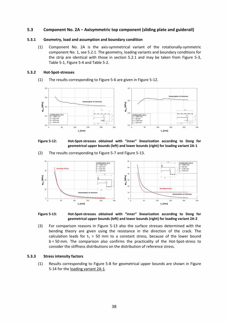
38
5.3 Component No. 2A – Axisymmetric top component (sliding plate and guiderail)
5.3.1 Geometry, load and assumption and boundary condition
(1) Component No. 2A is the axis-symmetrical variant of the rotationally-symmetric component No. 1, see 5.2.1. The geometry, loading variants and boundary conditions for the strip are identical with those in section 5.2.1 and may be taken from Figure 5-3, Table 5-1, Figure 5-4 and Table 5-2.
5.3.2 Hot-Spot-stresses
(1) The results corresponding to Figure 5-6 are given in Figure 5-12.
Figure 5-12: Hot-Spot-stresses obtained with “inner” linearization according to Dong for geometrical upper bounds (left) and lower bounds (right) for loading variant 2A-1
(2) The results corresponding to Figure 5-7 and Figure 5-13.
Figure 5-13: Hot-Spot-stresses obtained with “inner” linearization according to Dong for geometrical upper bounds (left) and lower bounds (right) for loading variant 2A-2
(3) For comparison reasons in Figure 5-13 also the surface stresses determined with the bending theory are given using the resistance in the direction of the crack. The calculation leads for t1 > 50 mm to a constant stress, because of the lower bound b = 50 mm. The comparison also confirms the practicality of the Hot-Spot-stress to consider the stiffness distributions on the distribution of reference stress.
5.3.3 Stress intensity factors
(1) Results corresponding to Figure 5-8 for geometrical upper bounds are shown in Figure 5-14 for the loading variant 2A-1.
0,0
0,2
0,4
0,6
0,8
0 50 100 150 200 250
H
S[M
Pa]
t1 [mm]
linearization of stresses
configuration 2A-1 D = 1800 mm b = 415 mm d = 970 mmt2 = 100 mm
0,0
2,0
4,0
6,0
0 50 100 150 200 250
HS
[MPa
]
t1 [mm]
linearization of stresses
configuration 2A-1 D = 1800 mm b = 50 mm d = 1700 mmt2 = 100 mm
0
10
20
30
40
0 50 100 150 200 250
H
S[M
Pa]
t1 [mm]
linearization of stresses
configuration 2A-2 D = 1800 mm b = 415 mm d = 970 mmt2 = 100 mm
bending theory
0
10
20
30
40
50
60
0 50 100 150 200 250
H
S[M
Pa]
t1 [mm]
linearization of stresses
configuration 2A-2 D = 1800 mm b = 50 mm d = 1700 mmt2 = 100 mm
bending theory

39
Figure 5-14: K-values (left) and normalised -values (right) related to HS = 1 N/mm2 for the
geometric upper bounds for loading variant 2A-1
(2) The function of the normalised -values related to HS = 1 N/mm² can be approximated by a polynomial of 3rd degree
= 35,4107747,2108441,110933,3 122
143
17 ttt (5-6)
(3) The results corresponding to Figure 5-9 for the geometrical lower bound are given in Figure 5-15.
Figure 5-15: K-values (left) and normalised -values (right) related to HS = 1 N/mm² for the geometric upper bounds for loading variant 2A-1
(4) The function of the normalised stress intensity factor in Figure 5-15 (right) can be approximated by a polynomial of 6th degree.
= -2,1617∙10-13t16+1,9489∙10-10t1
5–7,2084∙10-8t14+1,4030∙10-5t1
3
-1,5232∙10-3t12+8,8669∙10-2t1+1,0412
(5-7)
where is an approximation of K1.
(5) To confirm the insensitivity on other geometric parameters the influence of the width D of the sliding plate keeping the plate thickness t, constant is checked. The result in Figure 5-16 shows that the width D of the sliding plate has no significant influence on the K-values.
-1,0
-0,5
0,0
0,5
1,0
1,5
2,0
2,5
3,0
0 50 100 150 200 250stre
ss in
tens
ity fa
ctor
s K
1, K
2
t1 [mm]
configuration 2A-1 D = 1800 mm b = 415 mm d = 970 mmt2 = 100 mm
initial crack size a0
K1
K2
K = -4∙10-7t13 + 0,0002t1
2 - 0,0277t1 + 4,35R2 = 0,9862
0,0
1,0
2,0
3,0
4,0
5,0
0 50 100 150 200 250
stre
ss in
tens
ity fa
ctor
K
t1 [mm]
initial crack size a0
HS = const. = 1 N/mm
configuration 2A-1 D = 1800 mm b = 415 mm d = 970 mmt2 = 100 mm
K1
0
2
4
6
8
10
12
0 50 100 150 200 250
stre
ss in
tens
ity fa
ctor
K1,
K2
t1 [mm]
initial crack size a0
configuration 2A-1D = 1800 mm b = 50 mm d = 970 mmt2 = 100 mm
K1
K2
K = -2∙10-13t16 + 2∙10-10t1
5 - 7∙10-8t14 + 1∙10-5t1
3 - 0,0015t12 + 0,0887t1 + 1,0412
R2 = 0,9999
0,0
0,5
1,0
1,5
2,0
2,5
3,0
3,5
4,0
0 50 100 150 200 250
stre
ss in
tens
ity fa
ctor
K
t1 [mm]
initial crack size a0
HS = const. = 1 N/mm
K1
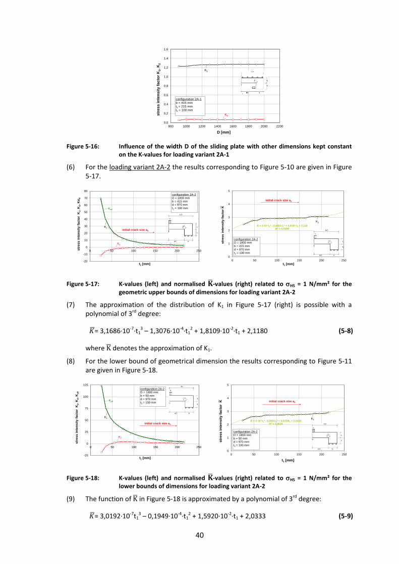
40
Figure 5-16: Influence of the width D of the sliding plate with other dimensions kept constant on the K-values for loading variant 2A-1
(6) For the loading variant 2A-2 the results corresponding to Figure 5-10 are given in Figure 5-17.
Figure 5-17: K-values (left) and normalised -values (right) related to HS = 1 N/mm² for the geometric upper bounds of dimensions for loading variant 2A-2
(7) The approximation of the distribution of K1 in Figure 5-17 (right) is possible with a polynomial of 3rd degree:
= 3,1686∙10-7∙t13 – 1,3076∙10-4∙t1
2 + 1,8109∙10-2∙t1 + 2,1180 (5-8)
where denotes the approximation of K1.
(8) For the lower bound of geometrical dimension the results corresponding to Figure 5-11 are given in Figure 5-18.
Figure 5-18: K-values (left) and normalised -values (right) related to HS = 1 N/mm² for the lower bounds of dimensions for loading variant 2A-2
(9) The function of in Figure 5-18 is approximated by a polynomial of 3rd degree:
= 3,0192∙10-7t13 – 0,1949∙10-4∙t1
2 + 1,5920∙10-2∙t1 + 2,0333 (5-9)
0,0
0,2
0,4
0,6
0,8
1,0
1,2
1,4
1,6
800 1000 1200 1400 1600 1800 2000 2200
stre
ss in
tens
ity fa
ctor
K1,
K2
D [mm]
configuration 2A-1b = 415 mm t1 = 215 mm t2 = 100 mm
K1
K2
-20
-10
0
10
20
30
40
50
60
70
80
0 50 100 150 200 250stre
ss in
tens
ity fa
ctor
K1,
K2,
Ke f
f
t1 [mm]
configuration 2A-2 D = 1800 mm b = 415 mm d = 970 mmt2 = 100 mm
initial crack size a0
K1
K2
Keff
K = 3∙10-7t13 - 0,0001∙t1
2 + 0,0181∙t1 + 2,118R2 = 0,9386
0
1
2
3
4
5
0 50 100 150 200 250
stre
ss in
tens
ity fa
ctor
K
t1 [mm]
configuration 2A-2 D = 1800 mm b = 415 mm d = 970 mmt2 = 100 mm
initial crack size a0
K1
-25
0
25
50
75
100
125
0 50 100 150 200 250
stre
ss in
tens
ity fa
ctor
K1,
K2,
Kef
f
t1 [mm]
initial crack size a0
configuration 2A-2D = 1800 mm b = 50 mm d = 970 mmt2 = 100 mm
K1
K2
Keff
K = 3∙10-7t13 - 0,0001t1
2 + 0,0159t1 + 2,0333R2 = 0,9624
0
1
2
3
4
5
0 50 100 150 200 250
stre
ss in
tens
ity fa
ctor
K
t1 [mm]
initial crack size a0
configuration 2A-2D = 1800 mm b = 50 mm d = 970 mmt2 = 100 mm
K1

41
where denotes the approximation of Keff.
(10) In contrast to Figure 5-16 the width D of the sliding plate is of significant influence for the loading variant 2A-2 as demonstrated in Figure 5-19.
Figure 5-19: Influence of the width D of the sliding plate with other dimensions kept constant on the K-values for loading variant 2A-2
5.3.4 Assessments to avoid brittle fracture
(1) The assessments to avoid brittle fracture are carried out as in section 5.2 for the loading variant 2A-1 in Table 5-9 and for loading variant 2A-2 in Table 5-10. The results of the calculations in Table 5-9 and Table 5-10 can be used to identify the maximum product thickness in Table 5-7 for loading variant 2A-1 in Table 5-8 for loading variant 2A-2.
Table 5-7: Limits of plate thickness t1 [mm] for the top component of bearing (loading variant 2A-1)
Steel grade acc. to
EN 10025 Ed 0°C -10°C -20°C -30°C -40°C -50°C
S355J2 0,25 ∙ fy 250*) 250*) 250*) 250*) 250*) 250*)
S355J2 0,50 ∙ fy 250*) 250*) 250*) 250*) 250*) 250*)
S355J2 0,75 ∙ fy 250*) 250*) 250*) 250*) 250*) 250*)
*) Assumption of a technical manufacturing limit (in theory element thicknesses with t ≥ 250 mm would be acceptable)
Table 5-8: Limits of plate thickness t1 [mm] for the top component of bearing (loading variant 2A-2)
Steel grade acc. to
EN 10025 Ed 0°C -10°C -20°C -30°C -40°C -50°C
S355J2 0,25 ∙ fy 250*) 250*)
250*) 250*)
250*) 250*)
S355J2 0,50 ∙ fy 250*) 250*)
250*) 250*)
250*) 250*)
S355J2 0,75 ∙ fy 250*) 250*)
250*) 250*)
250*) 240
*) Assumption of a technical manufacturing limit (in theory element thicknesses with t ≥ 250 mm would be acceptable)
0,0
0,5
1,0
1,5
2,0
2,5
3,0
3,5
4,0
800 1000 1200 1400 1600 1800 2000 2200
stre
ss in
tens
ity fa
ctor
K1,
K2
D [mm]
configuration 2A-2b = 415 mm t1 = 215 mm t2 = 100 mm
K1
K2
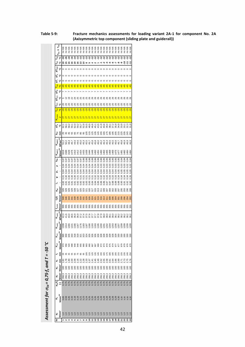
42
Table 5-9: Fracture mechanics assessments for loading variant 2A-1 for component No. 2A (Axisymmetric top component (sliding plate and guiderail))
Ass
essm
ent
for
Ed =
0,7
5∙f
y a
nd
T =
-50
°C
Nr
P
K1
Ed
/f y
P
Sa 0
t 1K
1,P
K1,
SK
1,ge
sK
1,ge
sf y,
nom
f y(t)
gy
L r
1
k R
6K
appl
,d
Kap
pl,d
b e
ff
T
KV,
nom
T KV
T 27J
T 2
7J
T R
T md
T r
T
T DC
FT E
dT R
d
N/m
m²
N/m
m3/
2[-]
N/m
m²
N/m
m²
mm
mm
N/m
m3/
2N
/mm
3/2
N/m
m3/
2M
Pam
1/2
N/m
m²
N/m
m²
N/m
m²
- -
- -
-N
/mm
3/2
MPa
m1/
2m
m°C
J°C
°C°C
°C°C
°C°C
°C°C
°C1
1,0
3,65
0,75
266,
310
01,
6125
973
365
1339
42,3
355
349
326
0,82
0,31
0,04
0,04
0,87
1619
51,2
2562
,127
-20
-20
57
-45
-50
019
-33
21,
03,
590,
7526
6,3
100
1,78
3595
635
913
1441
,635
534
632
90,
810,
300,
040,
040,
8715
8950
,235
58,1
27-2
0-2
012
7-4
5-5
00
15-2
63
1,0
3,45
0,75
266,
310
01,
9045
920
345
1265
40,0
355
344
329
0,81
0,30
0,04
0,04
0,87
1529
48,4
4558
,227
-20
-20
197
-45
-50
015
-19
41,
03,
330,
7526
6,3
100
2,00
5588
833
312
2138
,635
534
132
90,
810,
300,
040,
040,
8714
7646
,755
59,1
27-2
0-2
022
7-4
5-5
00
16-1
65
1,0
3,18
0,75
266,
310
02,
0965
848
318
1166
36,9
355
339
328
0,81
0,30
0,04
0,04
0,87
1410
44,6
6562
,027
-20
-20
247
-45
-50
019
-14
61,
03,
190,
7526
6,3
100
2,16
7584
831
911
6736
,935
533
632
70,
820,
310,
040,
040,
8714
1244
,675
59,2
27-2
0-2
025
7-4
5-5
00
16-1
37
1,0
3,21
0,75
266,
310
02,
2285
855
321
1176
37,2
355
334
325
0,82
0,31
0,04
0,04
0,87
1424
45,0
8555
,727
-20
-20
257
-45
-50
013
-13
81,
03,
230,
7526
6,3
100
2,28
9586
032
311
8337
,435
533
132
30,
820,
310,
040,
040,
8614
3345
,395
52,9
27-2
0-2
025
7-4
5-5
00
10-1
39
1,0
3,24
0,75
266,
310
02,
3310
586
332
411
8737
,535
532
932
10,
830,
310,
040,
040,
8614
3945
,510
550
,527
-20
-20
257
-45
-50
08
-13
101,
03,
250,
7526
6,3
100
2,37
115
865
325
1190
37,6
355
326
320
0,83
0,31
0,04
0,04
0,86
1444
45,7
115
48,5
27-2
0-2
026
7-4
5-5
00
5-1
211
1,0
3,26
0,75
266,
310
02,
4112
586
732
611
9337
,735
532
431
70,
840,
310,
040,
040,
8614
4945
,812
546
,627
-20
-20
267
-45
-50
04
-12
121,
03,
260,
7526
6,3
100
2,45
135
867
326
1193
37,7
355
321
315
0,84
0,32
0,04
0,04
0,86
1450
45,8
135
45,1
27-2
0-2
026
7-4
5-5
00
2-1
213
1,0
3,26
0,75
266,
310
02,
4914
586
932
611
9537
,835
531
931
30,
850,
320,
040,
030,
8614
5446
,014
543
,527
-20
-20
267
-45
-50
01
-12
141,
03,
280,
7526
6,3
100
2,52
155
872
328
1200
37,9
355
316
311
0,86
0,32
0,04
0,03
0,86
1460
46,2
155
41,9
27-2
0-2
026
7-4
5-5
00
-1-1
215
1,0
3,28
0,75
266,
310
02,
5516
587
332
812
0138
,035
531
430
90,
860,
320,
040,
030,
8514
6346
,316
540
,627
-20
-20
267
-45
-50
0-2
-12
161,
03,
280,
7526
6,3
100
2,58
175
874
328
1202
38,0
355
311
307
0,87
0,33
0,04
0,03
0,85
1465
46,3
175
39,4
27-2
0-2
026
7-4
5-5
00
-4-1
217
1,0
3,29
0,75
266,
310
02,
6118
587
532
912
0438
,135
530
930
40,
870,
330,
040,
030,
8514
6946
,518
538
,127
-20
-20
267
-45
-50
0-5
-12
181,
03,
280,
7526
6,3
100
2,64
195
874
328
1203
38,0
355
306
302
0,88
0,33
0,04
0,03
0,85
1469
46,5
195
37,2
27-2
0-2
026
7-4
5-5
00
-6-1
219
1,0
3,29
0,75
266,
310
02,
6620
587
732
912
0638
,135
530
430
00,
890,
330,
040,
030,
8514
7546
,620
535
,927
-20
-20
267
-45
-50
0-7
-12
201,
03,
300,
7526
6,3
100
2,69
215
877
330
1207
38,2
355
301
297
0,89
0,34
0,05
0,03
0,85
1477
46,7
215
34,9
27-2
0-2
026
7-4
5-5
00
-8-1
221
1,0
3,30
0,75
266,
310
02,
7122
587
933
012
0938
,235
529
929
50,
900,
340,
050,
030,
8414
8146
,822
533
,927
-20
-20
267
-45
-50
0-9
-12
221,
03,
300,
7526
6,3
100
2,73
235
879
330
1209
38,2
355
296
293
0,91
0,34
0,05
0,03
0,84
1482
46,9
235
33,1
27-2
0-2
026
7-4
5-5
00
-10
-12
231,
03,
300,
7526
6,3
100
2,75
245
879
330
1209
38,2
355
294
290
0,92
0,34
0,05
0,02
0,84
1484
46,9
245
32,3
27-2
0-2
026
7-4
5-5
00
-11
-12
231,
03,
300,
7526
6,3
100
2,76
250
879
330
1209
38,2
355
293
289
0,92
0,35
0,05
0,02
0,84
1484
46,9
250
31,9
27-2
0-2
026
7-4
5-5
00
-11
-12
no ri
sk
no ri
skno
risk
no ri
skno
risk
no ri
skno
risk
no ri
skno
risk
no ri
skno
risk
T Ed
≥ T
Rd
no ri
skno
risk
no ri
sk
no ri
skno
risk
no ri
skno
risk
no ri
sk
no ri
skno
risk
no ri
skno
risk
no ri
sk
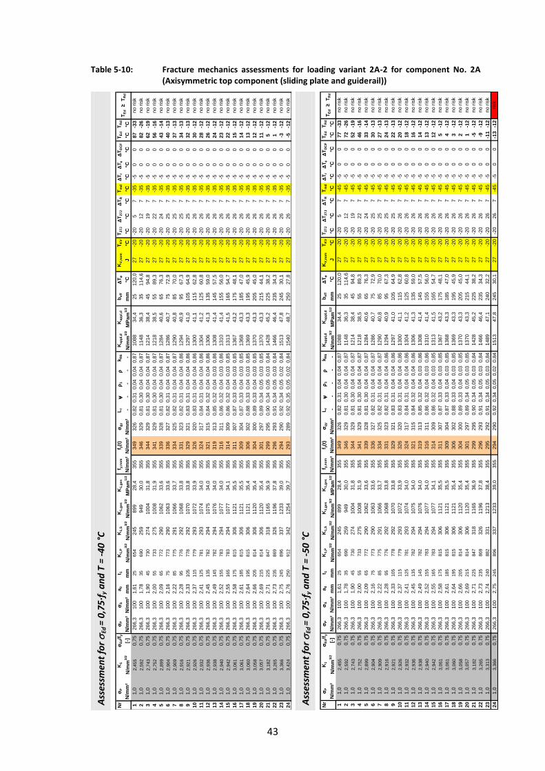
43
Table 5-10: Fracture mechanics assessments for loading variant 2A-2 for component No. 2A (Axisymmetric top component (sliding plate and guiderail))
Ass
essm
ent
for
Ed =
0,7
5∙f
y a
nd
T =
-40
°C
Ass
essm
ent
for
Ed =
0,7
5∙f
y a
nd
T =
-50
°C
Nr
P
K1
Ed
/f y
P
Sa 0
t 1K
1,P
K1,
SK
1,ge
sK
1,ge
sf y,
nom
f y(t)
gy
L r
1
k R
6K
appl
,d
Kap
pl,d
b e
ff
T
KV,
nom
T KV
T 27J
T 2
7J
T R
T md
T r
T
T DC
FT E
dT R
d
N/m
m²
N/m
m3/
2[-]
N/m
m²
N/m
m²
mm
mm
N/m
m3/
2N
/mm
3/2
N/m
m3/
2M
Pam
1/2
N/m
m²
N/m
m²
N/m
m²
- -
- -
-N
/mm
3/2
MPa
m1/
2m
m°C
J°C
°C°C
°C°C
°C°C
°C°C
°C1
1,0
2,45
50,
7526
6,3
100
1,61
2565
424
589
928
,435
534
932
60,
820,
310,
040,
040,
8710
8834
,425
120,
027
-20
-20
57
-35
-50
087
-33
21,
02,
592
0,75
266,
310
01,
7835
690
259
949
30,0
355
346
329
0,81
0,30
0,04
0,04
0,87
1148
36,3
3511
4,6
27-2
0-2
012
7-3
5-5
00
82-2
63
1,0
2,74
30,
7526
6,3
100
1,90
4573
027
410
0431
,835
534
432
90,
810,
300,
040,
040,
8712
1438
,445
94,8
27-2
0-2
019
7-3
5-5
00
62-1
94
1,0
2,75
20,
7526
6,3
100
2,00
5573
327
510
0831
,935
534
132
90,
810,
300,
040,
040,
8712
1838
,555
89,3
27-2
0-2
022
7-3
5-5
00
56-1
65
1,0
2,89
90,
7526
6,3
100
2,09
6577
229
010
6233
,635
533
932
80,
810,
300,
040,
040,
8712
8440
,665
76,3
27-2
0-2
024
7-3
5-5
00
43-1
46
1,0
2,90
40,
7526
6,3
100
2,16
7577
329
010
6333
,635
533
632
70,
820,
310,
040,
040,
8712
8640
,775
72,9
27-2
0-2
025
7-3
5-5
00
40-1
37
1,0
2,90
90,
7526
6,3
100
2,22
8577
529
110
6633
,735
533
432
50,
820,
310,
040,
040,
8712
9040
,885
70,0
27-2
0-2
025
7-3
5-5
00
37-1
38
1,0
2,91
60,
7526
6,3
100
2,28
9577
629
210
6833
,835
533
132
30,
820,
310,
040,
040,
8612
9440
,995
67,3
27-2
0-2
025
7-3
5-5
00
34-1
39
1,0
2,92
10,
7526
6,3
100
2,33
105
778
292
1070
33,8
355
329
321
0,83
0,31
0,04
0,04
0,86
1297
41,0
105
64,9
27-2
0-2
025
7-3
5-5
00
32-1
310
1,0
2,92
60,
7526
6,3
100
2,37
115
779
293
1072
33,9
355
326
320
0,83
0,31
0,04
0,04
0,86
1300
41,1
115
62,8
27-2
0-2
026
7-3
5-5
00
30-1
211
1,0
2,93
20,
7526
6,3
100
2,41
125
781
293
1074
34,0
355
324
317
0,84
0,31
0,04
0,04
0,86
1304
41,2
125
60,8
27-2
0-2
026
7-3
5-5
00
28-1
212
1,0
2,93
60,
7526
6,3
100
2,45
135
782
294
1075
34,0
355
321
315
0,84
0,32
0,04
0,04
0,86
1306
41,3
135
59,0
27-2
0-2
026
7-3
5-5
00
26-1
213
1,0
2,93
80,
7526
6,3
100
2,49
145
782
294
1076
34,0
355
319
313
0,85
0,32
0,04
0,03
0,86
1308
41,4
145
57,5
27-2
0-2
026
7-3
5-5
00
24-1
214
1,0
2,94
00,
7526
6,3
100
2,52
155
783
294
1077
34,0
355
316
311
0,86
0,32
0,04
0,03
0,86
1310
41,4
155
56,0
27-2
0-2
026
7-3
5-5
00
23-1
215
1,0
2,94
20,
7526
6,3
100
2,55
165
783
294
1077
34,1
355
314
309
0,86
0,32
0,04
0,03
0,85
1313
41,5
165
54,7
27-2
0-2
026
7-3
5-5
00
22-1
216
1,0
3,06
10,
7526
6,3
100
2,58
175
815
306
1121
35,5
355
311
307
0,87
0,33
0,04
0,03
0,85
1367
43,2
175
48,1
27-2
0-2
026
7-3
5-5
00
15-1
217
1,0
3,06
10,
7526
6,3
100
2,61
185
815
306
1121
35,5
355
309
304
0,87
0,33
0,04
0,03
0,85
1368
43,3
185
47,0
27-2
0-2
026
7-3
5-5
00
14-1
218
1,0
3,06
00,
7526
6,3
100
2,64
195
815
306
1121
35,4
355
306
302
0,88
0,33
0,04
0,03
0,85
1369
43,3
195
45,9
27-2
0-2
026
7-3
5-5
00
13-1
219
1,0
3,05
80,
7526
6,3
100
2,66
205
814
306
1120
35,4
355
304
300
0,89
0,33
0,04
0,03
0,85
1370
43,3
205
45,0
27-2
0-2
026
7-3
5-5
00
12-1
220
1,0
3,05
70,
7526
6,3
100
2,69
215
814
306
1120
35,4
355
301
297
0,89
0,34
0,05
0,03
0,85
1370
43,3
215
44,1
27-2
0-2
026
7-3
5-5
00
11-1
221
1,0
3,18
20,
7526
6,3
100
2,71
225
847
318
1165
36,9
355
299
295
0,90
0,34
0,05
0,03
0,84
1428
45,2
225
38,2
27-2
0-2
026
7-3
5-5
00
5-1
222
1,0
3,26
50,
7526
6,3
100
2,73
235
869
326
1196
37,8
355
296
293
0,91
0,34
0,05
0,03
0,84
1466
46,4
235
34,3
27-2
0-2
026
7-3
5-5
00
1-1
223
1,0
3,36
60,
7526
6,3
100
2,75
245
896
337
1233
39,0
355
294
290
0,92
0,34
0,05
0,02
0,84
1513
47,8
245
30,1
27-2
0-2
026
7-3
5-5
00
-3-1
224
1,0
3,42
40,
7526
6,3
100
2,76
250
912
342
1254
39,7
355
293
289
0,92
0,35
0,05
0,02
0,84
1540
48,7
250
27,8
27-2
0-2
026
7-3
5-5
00
-5-1
2no
risk
no ri
sk
no ri
skno
risk
no ri
skno
risk
no ri
skno
risk
no ri
skno
risk
T Ed
≥ T
Rd
no ri
sk
no ri
skno
risk
no ri
skno
risk
no ri
sk
no ri
skno
risk
no ri
skno
risk
no ri
skno
risk
no ri
skno
risk
Nr
P
K1
Ed
/f y
P
Sa 0
t 1K
1,P
K1,
SK
1,ge
sK
1,ge
sf y,
nom
f y(t)
gy
L r
1
k R
6K
appl
,d
Kap
pl,d
b e
ff
T
KV,
nom
T KV
T 27J
T 2
7J
T R
T md
T r
T
T DC
FT E
dT R
d
N/m
m²
N/m
m3/
2[-]
N/m
m²
N/m
m²
mm
mm
N/m
m3/
2N
/mm
3/2
N/m
m3/
2M
Pam
1/2
N/m
m²
N/m
m²
N/m
m²
- -
- -
-N
/mm
3/2
MPa
m1/
2m
m°C
J°C
°C°C
°C°C
°C°C
°C°C
°C1
1,0
2,45
50,
7526
6,3
100
1,61
2565
424
589
928
,435
534
932
60,
820,
310,
040,
040,
8710
8834
,425
120,
027
-20
-20
57
-45
-50
077
-33
21,
02,
592
0,75
266,
310
01,
7835
690
259
949
30,0
355
346
329
0,81
0,30
0,04
0,04
0,87
1148
36,3
3511
4,6
27-2
0-2
012
7-4
5-5
00
72-2
63
1,0
2,74
30,
7526
6,3
100
1,90
4573
027
410
0431
,835
534
432
90,
810,
300,
040,
040,
8712
1438
,445
94,8
27-2
0-2
019
7-4
5-5
00
52-1
94
1,0
2,75
20,
7526
6,3
100
2,00
5573
327
510
0831
,935
534
132
90,
810,
300,
040,
040,
8712
1838
,555
89,3
27-2
0-2
022
7-4
5-5
00
46-1
65
1,0
2,89
90,
7526
6,3
100
2,09
6577
229
010
6233
,635
533
932
80,
810,
300,
040,
040,
8712
8440
,665
76,3
27-2
0-2
024
7-4
5-5
00
33-1
46
1,0
2,90
40,
7526
6,3
100
2,16
7577
329
010
6333
,635
533
632
70,
820,
310,
040,
040,
8712
8640
,775
72,9
27-2
0-2
025
7-4
5-5
00
30-1
37
1,0
2,90
90,
7526
6,3
100
2,22
8577
529
110
6633
,735
533
432
50,
820,
310,
040,
040,
8712
9040
,885
70,0
27-2
0-2
025
7-4
5-5
00
27-1
38
1,0
2,91
60,
7526
6,3
100
2,28
9577
629
210
6833
,835
533
132
30,
820,
310,
040,
040,
8612
9440
,995
67,3
27-2
0-2
025
7-4
5-5
00
24-1
39
1,0
2,92
10,
7526
6,3
100
2,33
105
778
292
1070
33,8
355
329
321
0,83
0,31
0,04
0,04
0,86
1297
41,0
105
64,9
27-2
0-2
025
7-4
5-5
00
22-1
310
1,0
2,92
60,
7526
6,3
100
2,37
115
779
293
1072
33,9
355
326
320
0,83
0,31
0,04
0,04
0,86
1300
41,1
115
62,8
27-2
0-2
026
7-4
5-5
00
20-1
211
1,0
2,93
20,
7526
6,3
100
2,41
125
781
293
1074
34,0
355
324
317
0,84
0,31
0,04
0,04
0,86
1304
41,2
125
60,8
27-2
0-2
026
7-4
5-5
00
18-1
212
1,0
2,93
60,
7526
6,3
100
2,45
135
782
294
1075
34,0
355
321
315
0,84
0,32
0,04
0,04
0,86
1306
41,3
135
59,0
27-2
0-2
026
7-4
5-5
00
16-1
213
1,0
2,93
80,
7526
6,3
100
2,49
145
782
294
1076
34,0
355
319
313
0,85
0,32
0,04
0,03
0,86
1308
41,4
145
57,5
27-2
0-2
026
7-4
5-5
00
14-1
214
1,0
2,94
00,
7526
6,3
100
2,52
155
783
294
1077
34,0
355
316
311
0,86
0,32
0,04
0,03
0,86
1310
41,4
155
56,0
27-2
0-2
026
7-4
5-5
00
13-1
215
1,0
2,94
20,
7526
6,3
100
2,55
165
783
294
1077
34,1
355
314
309
0,86
0,32
0,04
0,03
0,85
1313
41,5
165
54,7
27-2
0-2
026
7-4
5-5
00
12-1
216
1,0
3,06
10,
7526
6,3
100
2,58
175
815
306
1121
35,5
355
311
307
0,87
0,33
0,04
0,03
0,85
1367
43,2
175
48,1
27-2
0-2
026
7-4
5-5
00
5-1
217
1,0
3,06
10,
7526
6,3
100
2,61
185
815
306
1121
35,5
355
309
304
0,87
0,33
0,04
0,03
0,85
1368
43,3
185
47,0
27-2
0-2
026
7-4
5-5
00
4-1
218
1,0
3,06
00,
7526
6,3
100
2,64
195
815
306
1121
35,4
355
306
302
0,88
0,33
0,04
0,03
0,85
1369
43,3
195
45,9
27-2
0-2
026
7-4
5-5
00
3-1
219
1,0
3,05
80,
7526
6,3
100
2,66
205
814
306
1120
35,4
355
304
300
0,89
0,33
0,04
0,03
0,85
1370
43,3
205
45,0
27-2
0-2
026
7-4
5-5
00
2-1
220
1,0
3,05
70,
7526
6,3
100
2,69
215
814
306
1120
35,4
355
301
297
0,89
0,34
0,05
0,03
0,85
1370
43,3
215
44,1
27-2
0-2
026
7-4
5-5
00
1-1
221
1,0
3,18
20,
7526
6,3
100
2,71
225
847
318
1165
36,9
355
299
295
0,90
0,34
0,05
0,03
0,84
1428
45,2
225
38,2
27-2
0-2
026
7-4
5-5
00
-5-1
222
1,0
3,26
50,
7526
6,3
100
2,73
235
869
326
1196
37,8
355
296
293
0,91
0,34
0,05
0,03
0,84
1466
46,4
235
34,3
27-2
0-2
026
7-4
5-5
00
-9-1
223
1,0
3,31
30,
7526
6,3
100
2,74
240
882
331
1213
38,4
355
295
292
0,91
0,34
0,05
0,03
0,84
1489
47,1
240
32,2
27-2
0-2
026
7-4
5-5
00
-11
-12
241,
03,
366
0,75
266,
310
02,
7524
589
633
712
3339
,035
529
429
00,
920,
340,
050,
020,
8415
1347
,824
530
,127
-20
-20
267
-45
-50
0-1
3-1
2
no ri
sk
no ri
skno
risk
no ri
skno
risk
no ri
skno
risk
no ri
skno
risk
no ri
skno
risk
no ri
skno
risk
T Ed
≥ T
Rd
no ri
sk
no ri
skris
k
no ri
skno
risk
no ri
skno
risk
no ri
skno
risk
no ri
skno
risk

44
5.4 Component No. 2B – Axisymmetric top component of reference bearing type B (welded variant)
5.4.1 Geometry, load assumptions and boundary conditions
(1) Component No. 2B has the same function as top component No. 2A except that the axisymmetric component is built up by welding according to Figure 5-20.
Figure 5-20: Component 2B: top component of reference type B (sliding plate and guiderail)
(2) Table 5-11 gives the numerical values of the dimensions.
Table 5-11: Ranges of geometrical dimensions for detail 2B
t1 [mm] t2 [mm] D [mm] b [mm] aw [mm]
55 - 285 55 - 170 440 – 2580 55 - 570 12 - 42
(3) In analogy to the investigations in section 5.2 and section 5.3 two loading variants, one with horizontal loading, the other with vertical loading were studied.
(4) The toes of the welds are the potential spots for crack initiation.
(5) For determining the limitation of the plate thickness t2 the loading variants 2B-1 and 2B-2 were used.
The positions of crack in the guiderails were assumed as given in Figure 5-21. The initial crack depth a0 depends on the thickness t2. In these regions no significant tensile stresses have to be expected under realistic external loading conditions.
Loading variant 2B-1 Loading variant 2B-2
Figure 5-21: Variants for loading for detail 2B: Variant 2B-1 with horizontal loading (left); variant 2B-2 with vertical loading (right)
(6) For determining the limitation of the plate thickness t1 the models with the loading variants
- 2B-3,
- 2B-4,
- 2B-5,

45
- 2B-6,
were used. The crack configuration for the loading variants 2B-3 and 2B-4 is rather hypothetical, see Figure 5-22. The initial crack size for these variants depends on the thickness t1 of the sliding plate. The occurrence of the cracks in Figure 5-22 is also rather hypothetical as no significant stresses have to be expected from realistic external loading conditions.
Loading variant 2B-3 Loading variant 2B-4
Figure 5-22: Loading variants for detail 2B: Variant 2B-3 with horizontal loading (left) and variant 2B-4 with vertical loading (right)
(7) A further crack configuration is assumed at the re-entrant corner as shown in Figure 5-23. For this crack configuration preliminary studies showed that the crack-orientation with 45 ° was more severe than a vertical orientation. The initial crack length depends on the plate thickness t1 of the sliding plate. Tensile stresses in this region are realistic.
Loading variant 2B-5 Loading variant 2B-6
Figure 5-23: Loading variants for detail 2B: Variant 2B-5 with horizontal loading (left) and variant 2B-6 with vertical loading (right)
(8) The calculations were carried out for two different configurations of the dimensions of the bearings in Table 5-12 for the variation of t2 and in Table 5-13 for the variation of t1.
The influence of the geometry of the welds on the K-value is only small when thickness is increased. The maximum possible weld thickness of aw = 42 mm was assumed for the upper bound of the geometrical dimensions. For the lower bound of the geometrical dimensions a throat thickness of aw = 16 mm was used.

46
Table 5-12: Upper and lower bounds of geometrical dimensions for component No. 2B for determining the limit of plate thickness t2
Upper bounds Lower bounds
t1 [mm] 285 t1 [mm] 55
t2 [mm] 50-200 t2 [mm] 50 – 200
D [mm] 2580 D [mm] 2580
d [mm] 1980 d [mm] 2525
b [mm] 570 b [mm] 55
aw [mm] 42 aw [mm] 16
Table 5-13: Upper and lower bounds of geometrical dimensions for component No. 2B for determining the limit of plate thickness t1
Upper bounds Lower bounds
t1 [mm] 55 – 285 t1 [mm] 55 – 285
t2 [mm] 170 t2 [mm] 170
D [mm] 2580 D [mm] 2580
d [mm] 1980 d [mm] 2525
b [mm] 570 b [mm] 55
aw [mm] 42 aw [mm] 16
(9) In Figure 5-24 to Figure 5-26 examples are given for the FE-models used (sections only) together with the associated deformations and crack opening.
Figure 5-24: Section from a FE-model (left) and from the plot of deformations including crack-opening (right) for loading variant 2B-1 and 2B-2
Figure 5-25: Section from a FE-model (left) and from the plot of deformations including crack-opening (right) for loading variant 2B-3 and 2B-4

47
Figure 5-26: Section from a FE-model (left) and from the plot of deformations including crack-opening (right) for loading variant 2B-5 and 2B-6
5.4.2 Hot-Spots-stresses
(1) For loading variant 2B-1 the reference stress of the fracture mechanics assessment is identical with the stress loading applied to the FE-model.
(2) For loading variant 2B-2 Figure 5-27 (left) shows the Hot-Spot-stress increasing linearly with increasing thickness t2 of the guiderail for the upper bound of the geometrical dimensions.
(3) The decreasing effect of thickness t2 on the Hot-Spot-stresses for the lower bound of geometrical dimensions is given in Figure 5-27 (right). The decrease is also linear.
Figure 5-27: Hot-spot-stresses due to external stress loading (unit stress) for loading variant 2B-2: vertical loading: upper bound of geometrical dimensions (left), lower bound of geometrical dimensions (right)
(4) Figure 5-28 (left) gives for loading variant 2B-3 the function of Hot-Spot-stresses for the variation of the plate thickness t1 at the upper bound of geometrical dimensions. The numerical values are rather small and decrease with increasing value of t1.
(5) Figure 5-28 (right) gives a similar performance for the lower bound of the geometrical dimensions. For t > 160 mm the further distribution can be linearly approximated.
0,00
0,05
0,10
0,15
0,20
0,25
50 100 150 200
H
S[M
Pa]
t2 [mm]
linearization of stressesconfiguration 2B-2D = 2580 mm b = 570 mm d = 1980 mmt1 = 285 mm aw = 42 mm
4
6
8
10
50 100 150 200
H
S[M
Pa]
t2 [mm]
linearization of stresses
configuration 2B-2D = 2580 mm b = 55 mm d = 2525 mmt1 = 55 mm aw = 16 mm

48
Figure 5-28: Hot-Spot-stresses due to external stress loading (unit stress) for loading variant 2B-3: horizontal loading; upper bound of geometrical dimensions (left), lower bound of geometrical dimensions (right)
(6) According to Figure 5-29 (left) the Hot-Spot-stresses for loading variant 2B-4 increase with increasing plate thickness t1 for the upper bound of geometrical dimensions.
(7) Figure 5-29 (right) shows the corresponding distribution of the Hot-Spot-stresses for the lower bound of the geometrical dimensions. In the range 25 mm ≤ t1 ≤ 55 mm the increase is strong; for t1 > 55 mm there is an exponential decrease.
Figure 5-29: Hot-Spot-stresses due to external unit loading for loading variant 2B-4: vertical loading; upper bound of geometrical dimensions (left), lower bound of geometrical dimensions (right)
(8) For loading variant 2B-5 Figure 5-30 shows the Hot-Spot-stresses for the upper bound of geometrical dimensions .
(9) In Figure 5-30 (right) the Hot-Spot-stresses for the lower bound of geometrical dimensions are shown.
Figure 5-30: Hot-Spot-stresses due to external unit load for loading variant 2B-5 with horizontal loading: for upper bound of geometrical dimensions (left), lower bound of geometrical dimensions (right)
0,00
0,05
0,10
0,15
0,20
0 50 100 150 200 250 300
H
S[M
Pa]
t1 [mm]
linearization of stresses
configuration 2B-3D = 2580 mm b = 570 mm d = 1980 mmt2 = 170 mm aw = 42 mm
HS = -0,003∙t1 + 10,408
8
10
12
14
16
0 50 100 150 200 250 300
H
S[M
Pa]
t1 [mm]
linearization of stresses
configuration 2B-3D = 2580 mm b = 55 mm d = 2525 mmt2 = 170 mm aw = 16 mm
0,00
0,10
0,20
0,30
0,40
0,50
0,60
0 50 100 150 200 250 300
H
S[M
Pa]
t1 [mm]
linearization of stressesconfiguration 2B-4D = 2580 mm b = 570 mm d = 1980 mmt2 = 170 mm aw = 42 mm
HS = 105,72e-0,0194∙t1
R2 = 0,9998
0
5
10
15
20
25
30
0 50 100 150 200 250 300
H
S[M
Pa]
t1 [mm]
linearization of stresses
configuration 2B-4D = 2580 mm b = 55 mm d = 2525 mmt2 = 170 mm aw = 16 mm
0,0
0,2
0,4
0,6
0 50 100 150 200 250 300
H
S[M
Pa]
t1 [mm]
linearization of stresses
configuration 2B-5D = 2580 mm b = 570 mm d = 1980 mmt2 = 170 mm aw = 42 mm
0
5
10
15
20
0 50 100 150 200 250
H
S[M
Pa]
t1 [mm]
linearization of stresses
configuration 2B-5D = 2580 mm b = 55 mm d = 2525 mmt2 = 170 mm e = 27,5 mmaw = 16 mm

49
(10) Figure 5-31 (left) gives for loading variant 2B-6 the monotonously decreasing of the Hot-Spot stress for large plate thicknesses t1 for the upper bound of the geometrical dimensions.
(11) In Figure 5-31 (right) the decrease of the Hot-Spot-stresses for large plate thicknesses t1 is shown for the lower bound of the geometric dimension.
Figure 5-31: Hot-Spot-stresses due to external unit load for loading variant 2B-6 vertical load: for upper bound of geometrical dimensions (left), lower bound of geometrical dimensions (right)
5.4.3 Stress intensity factors
(1) For the loading variant 2B-1 Figure 5-32 shows the almost linear increase of the K-value with increasing plate thickness t2 of the guiderail for the upper bound of the geometrical dimensions. The influence of mode 2-stresses is negligible.
Figure 5-32: -values for HS = 1 N/mm2 for loading variant 2B-1, horizontal loading for
variation of plate thickness t2; upper bound of geometrical dimensions
(2) Figure 5-33 shows the distribution of the -values due to HS = 1 N/mm2 for the loading variant 2B-1 for the lower bound of the geometrical dimensions. The -values decrease with increasing thickness t2 of the guiderail due to the geometry and support conditions chosen. This effects for large t2-values an increasing influence of mode 2-stresses.
Figure 5-33: -values for HS = 1 N/mm2 for loading variant 2B-1, horizontal loading; variation
of plate thickness t2; lower bound of geometrical dimensions
0
2
4
6
8
10
12
0 50 100 150 200 250 300
H
S[M
Pa]
t1 [mm]
linearization of stresses
configuration 2B-6D = 2580 mm b = 570 mm d = 1980 mmt2 = 170 mm aw = 42 mm
0
20
40
60
80
100
0 50 100 150 200 250
H
S[M
Pa]
t1 [mm]
linearization of stresses configuration 2B-6D = 2580 mm b = 55 mm d = 2525 mmt2 = 170 mm e = 27,5 mmaw = 16 mm
-5
0
5
10
15
50 100 150 200
stre
ss in
tens
ity fa
ctor
K
t2 [mm]
initial crack size a0
configuration 2B-1D = 2580 mm b = 570 mm d = 1980 mmt1 = 285 mm aw = 42 mm
Keff
K2
K1
N = const. = 1 N/mm
-2
0
2
4
6
0 50 100 150 200
stre
ss in
tens
ity fa
ctor
K
t2 [mm]
initial crack size a0
configuration 2B-1D = 2580 mm b = 55 mm d = 2525 mmt1 = 285 mm aw = 16 mm Keff
K1
K2
N = const. = 1 N/mm
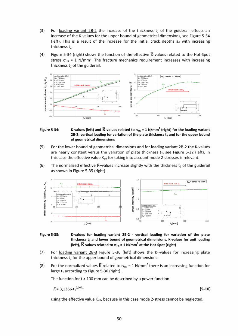
50
(3) For loading variant 2B-2 the increase of the thickness t2 of the guiderail effects an increase of the K-values for the upper bound of geometrical dimensions, see Figure 5-34 (left). This is a result of the increase for the initial crack depths a0 with increasing thickness t2.
(4) Figure 5-34 (right) shows the function of the effective -values related to the Hot-Spot
stress HS = 1 N/mm2. The fracture mechanics requirement increases with increasing thickness t2 of the guiderail.
Figure 5-34: K-values (left) and -values related to HS = 1 N/mm2 (right) for the loading variant
2B-2: vertical loading for variation of the plate thickness t2 and for the upper bound of geometrical dimensions
(5) For the lower bound of geometrical dimensions and for loading variant 2B-2 the K-values are nearly constant versus the variation of plate thickness t2, see Figure 5-32 (left). In this case the effective value Keff for taking into account mode 2-stresses is relevant.
(6) The normalized effective –values increase slightly with the thickness t2 of the guiderail as shown in Figure 5-35 (right).
Figure 5-35: K-values for loading variant 2B-2 - vertical loading for variation of the plate thickness t2 and lower bound of geometrical dimensions. K-values for unit loading
(left), -values related to HS = 1 N/mm2 at the Hot-Spot (right)
(7) For loading variant 2B-3 Figure 5-36 (left) shows the K1-values for increasing plate thickness t1 for the upper bound of geometrical dimensions.
(8) For the normalized values related to HS = 1 N/mm2 there is an increasing function for large t1 according to Figure 5-36 (right).
The function for t > 100 mm can be described by a power function
= 3,1366∙t10,0071 (5-10)
using the effective value Keff, because in this case mode 2-stress cannot be neglected.
-0,4
-0,2
0,0
0,2
0,4
0,6
0,8
1,0
50 100 150 200
stre
ss in
tens
ity fa
ctor
K1,
K2,
Kef
f
t2 [mm]
configuration 2B-2D = 2580 mm b = 570 mm d = 1980 mmt1 = 285 mm aw = 42 mm initial crack size a0
Keff
K1
K20
1
2
3
4
5
50 100 150 200
stre
ss in
tens
ity fa
ctor
K
t2 [mm]
configuration 2B-2D = 2580 mm b = 570 mm d = 1980 mmt1 = 285 mm aw = 42 mm
HS = const. = 1 N/mm
initial crack size a0
Keff
-10
-5
0
5
10
15
50 100 150 200
stre
ss in
tens
ity fa
ctor
K1,
K2,
Kef
f
t2 [mm]
configuration 2B-2D = 2580 mm b = 55 mm t1 = 285 mm e = 27,5 mmaw = 16 mm
initial crack size a0Keff
K1
K20,0
0,5
1,0
1,5
2,0
50 100 150 200
stre
ss in
tens
ity fa
ctor
K
t2 [mm]
configuration 2B-2D = 2580 mm b = 55 mm t1 = 285 mm e = 27,5 mmaw = 16 mm
initial crack size a0
HS = const. = 1 N/mm
Keff

51
Figure 5-36: K-values for loading variant 2B-3 - horizontal loading for variation of the plate thickness t1 and upper bound of geometrical dimensions; K-values for unit loading
(left), -values related to HS = 1 N/mm2 at the Hot-Spot (right)
(9) A qualitatively similar performance is shown for the lower bounds of geometrical dimensions in Figure 5-37 (left). The magnitudes of K-values are larger.
(10) The normalised -values taking into account mode 2-stresses are increasing with increasing plate thickness t1, see Figure 5-37 (right).
The function can be described by the power function
= 1,3661∙t11,1052 (5-11)
Figure 5-37: K-values for loading variant 2B-3 - horizontal loading for variation of the plate thickness t1 and upper bound of geometrical dimensions; K-values for unit loading
(left), -values related to HS = 1 N/mm2 at the Hot-Spot (right)
(11) For loading variant 2B-4 the K-values for the upper bound of the geometrical dimensions are increasing to a maximum value for t1 = 250 mm and then slightly decrease, see Figure 5-38 (left).
(12) The normalized effective -value related to HS = 1 N/mm2 relevant for the assessment to avoid brittle failure may be taken from Figure 5-38 (right). The maximum is obtained for t1 = 180 mm, and for t1 > 180 mm there is a decrease. The function can be described for the range 190 mm ≤ t1 ≤ 300 mm by a polynomial of 3rd degree:
= -5,01730∙10-7∙t13+4,09628∙10-4∙t1
2–1,12831∙10-1∙t1+13,8884 (5-12)
0,0
0,2
0,4
0,6
0,8
1,0
50 100 150 200 250 300
stre
ss in
tens
ity fa
ctor
K1,
K2
t1 [mm]
configuration 2B-3D = 2580 mm b = 570 mm d = 1980 mmt2 = 170 mm e = 270 mmaw = 42 mm
initial crack size a0
K1
K2
K = 3,1366t10,0771
R2 = 0,9987
3,0
3,5
4,0
4,5
5,0
50 100 150 200 250 300
stre
ss in
tens
ity fa
ctor
K
t1 [mm]
configuration 2B-3D = 2580 mm b = 570 mm d = 1980 mmt2 = 170 mm aw = 42 mmHS = const. = 1 N/mm
initial crack size a0
Keff
0
5
10
15
20
25
0 50 100 150 200 250
stre
ss in
tens
ity fa
ctor
K1,
K2
t1 [mm]
initial crack size a0
configuration 2B-3D = 2580 mm b = 55 mm d = 2525 mmt2 = 170 mm e = 27,5 mmaw = 16 mm
K1
K2
K = 1,3661t10,1052
R2 = 0,9909
1,0
1,5
2,0
2,5
3,0
0 50 100 150 200 250 300
stre
ss in
tens
ity fa
ctor
K
t1 [mm]
initial crack size a0
configuration 2B-3D = 2580 mm b = 55 mm d = 2525 mmt2 = 170 mm aw = 16 mm
HS = const. = 1 N/mm
Keff
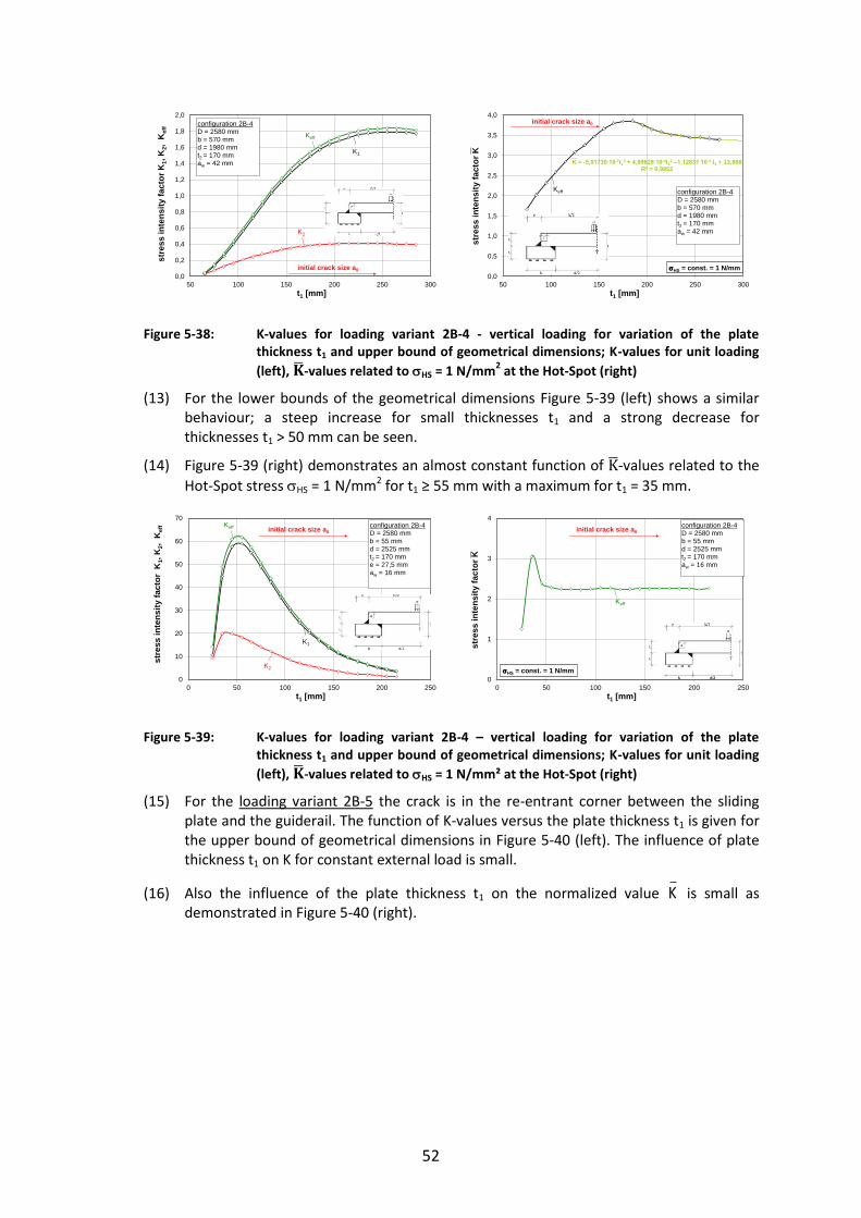
52
Figure 5-38: K-values for loading variant 2B-4 - vertical loading for variation of the plate thickness t1 and upper bound of geometrical dimensions; K-values for unit loading
(left), -values related to HS = 1 N/mm2 at the Hot-Spot (right)
(13) For the lower bounds of the geometrical dimensions Figure 5-39 (left) shows a similar behaviour; a steep increase for small thicknesses t1 and a strong decrease for thicknesses t1 > 50 mm can be seen.
(14) Figure 5-39 (right) demonstrates an almost constant function of -values related to the
Hot-Spot stress HS = 1 N/mm2 for t1 ≥ 55 mm with a maximum for t1 = 35 mm.
Figure 5-39: K-values for loading variant 2B-4 – vertical loading for variation of the plate thickness t1 and upper bound of geometrical dimensions; K-values for unit loading
(left), -values related to HS = 1 N/mm² at the Hot-Spot (right)
(15) For the loading variant 2B-5 the crack is in the re-entrant corner between the sliding plate and the guiderail. The function of K-values versus the plate thickness t1 is given for the upper bound of geometrical dimensions in Figure 5-40 (left). The influence of plate thickness t1 on K for constant external load is small.
(16) Also the influence of the plate thickness t1 on the normalized value K is small as demonstrated in Figure 5-40 (right).
0,0
0,2
0,4
0,6
0,8
1,0
1,2
1,4
1,6
1,8
2,0
50 100 150 200 250 300
stre
ss in
tens
ity fa
ctor
K1,
K2,
Kef
f
t1 [mm]
configuration 2B-4D = 2580 mm b = 570 mm d = 1980 mmt2 = 170 mm aw = 42 mm
initial crack size a0
K1
K2
Keff
K = -5,01730∙10-7t13 + 4,09628∙10-4t1
2 –1,12831∙10-1 t1 + 13,888R2 = 0,9952
0,0
0,5
1,0
1,5
2,0
2,5
3,0
3,5
4,0
50 100 150 200 250 300
stre
ss in
tens
ity fa
ctor
K
t1 [mm]
configuration 2B-4D = 2580 mm b = 570 mm d = 1980 mmt2 = 170 mm aw = 42 mm
HS = const. = 1 N/mm
initial crack size a0
Keff
0
10
20
30
40
50
60
70
0 50 100 150 200 250
stre
ss in
tens
ity fa
ctor
K1,
K2,
Kef
f
t1 [mm]
initial crack size a0configuration 2B-4D = 2580 mm b = 55 mm d = 2525 mmt2 = 170 mm e = 27,5 mmaw = 16 mm
K1
Keff
K2
0
1
2
3
4
0 50 100 150 200 250
stre
ss in
tens
ity fa
ctor
K
t1 [mm]
initial crack size a0configuration 2B-4D = 2580 mm b = 55 mm d = 2525 mmt2 = 170 mm aw = 16 mm
HS = const. = 1 N/mm
Keff

53
Figure 5-40: K-values for loading variant 2B-5 - horizontal loading for variation of the plate thickness t1 and upper bounds of geometrical dimensions; K-values for unit loading
(left); -values related to HS = 1 N/mm2 at the Hot-Spot (right)
(17) Figure 5-41 (left) shows the monotonous increase of K-values versus plate thickness t1 for the loading variant 2B-5 and for the lower bound of geometrical dimensions. In comparison with the value in Figure 5-40 (left) the K-values are larger but do not vary much around a certain level.
(18) The -value normalised to HS = 1 N/mm2 gives the function according to Figure 5-41 (right). For t1 > 215 mm this function can be approximated by = 2,0352e0,0006t1.
Figure 5-41: K-values for loading variant 2B-5 - horizontal loading for variation of the plate thickness t1 and upper bounds of geometrical dimensions; K-values for unit loading
(left); -values related to HS = 1 N/mm2 at the Hot-Spot (right)
(19) For loading variant 2B-6 the K-values decrease for large values of t1, for the upper bound of geometrical dimensions, see Figure 5-42 (left).
(20) The normalised values related to HS = 1 N/mm2 produce however a nearly constant function versus the plate thickness t1, see Figure 5-42 (right).
-0,5
0,0
0,5
1,0
1,5
2,0
50 100 150 200 250 300
stre
ss in
tens
ity fa
ctor
K1,
K2
t1 [mm]
configuration 2B-5D = 2580 mm b = 570 mm d = 1980 mmt2 = 170 mm e = 270 mmaw = 42 mm
initial crack size a0
K1
K20,0
1,0
2,0
3,0
4,0
50 100 150 200 250 300
Sstr
ess
inte
nsity
fact
or K
t1 [mm]
configuration 2B-5D = 2580 mm b = 570 mm d = 1980 mmt2 = 170 mm aw = 42 mm
HS = const. = 1 N/mm
initial crack size a0
K1
-5,0
0,0
5,0
10,0
15,0
20,0
25,0
30,0
35,0
0 50 100 150 200 250
stre
ss in
tens
ity fa
ctor
K1,
K2
t1 [mm]
initial crack size a0
configuration 2B-5D = 2580 mm b = 55 mm d = 2525 mmt2 = 170 mm e = 27,5 mmaw = 16 mm
K1
K2
K = 2,0352e0,0006t1
0,0
0,5
1,0
1,5
2,0
2,5
3,0
0 50 100 150 200 250 300
stre
ss in
tens
ity fa
ctor
K
t1 [mm]
HS = const. = 1 N/mm
initial crack size a0
configuration 2B-5D = 2580 mm b = 55 mm d = 2525 mmt1 = 285 mm e = 27,5 mmaw = 16 mm
K1
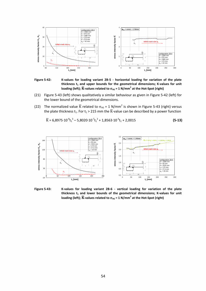
54
Figure 5-42: K-values for loading variant 2B-5 - horizontal loading for variation of the plate thickness t1 and upper bounds for the geometrical dimensions; K-values for unit
loading (left); -values related to HS = 1 N/mm2 at the Hot-Spot (right)
(21) Figure 5-43 (left) shows qualitatively a similar behaviour as given in Figure 5-42 (left) for the lower bound of the geometrical dimensions.
(22) The normalized value related to HS = 1 N/mm2 is shown in Figure 5-43 (right) versus the plate thickness t1. For t1 > 215 mm the -value can be described by a power function
= 6,8975∙10-9t13 – 5,8020∙10-7t1
2 + 1,8563∙10-3t1 + 2,0015 (5-13)
Figure 5-43: K-values for loading variant 2B-6 - vertical loading for variation of the plate thickness t1 and lower bounds of the geometrical dimensions; K-values for unit
loading (left); -values related to HS = 1 N/mm2 at the Hot-Spot (right)
0
10
20
30
40
60 110 160 210 260
stre
ss in
tens
ity fa
ctor
K1,
K2
t1 [mm]
configuration 2B-6D = 2580 mm b = 570 mm d = 1980 mmt2 = 170 mm e = 270 mmaw = 42 mm
initial crack size a0
K1
K2
0
1
2
3
4
0 50 100 150 200 250 300
stre
ss in
tens
ity fa
ctor
K
t1 [mm]
configuration 2B-6D = 2580 mm b = 570 mm d = 1980 mmt2 = 170 mm aw = 42 mm
HS = const. = 1 N/mm
initial crack size a0K1
-20
30
80
130
180
0 50 100 150 200 250
stre
ss in
tens
ity fa
ctor
K1,
K2
t1 [mm]
initial crack size a0
configuration 2B-6D = 2580 mm b = 55 mm d = 2525 mmt2 = 170 mm e = 27,5 mmaw = 16 mm
K1
K2
K = 7∙10-9t13 - 6∙10-7t1
2 + 0,0019t1 + 2,0015
0,0
0,5
1,0
1,5
2,0
2,5
3,0
0 50 100 150 200 250 300
stre
ss in
tens
ity fa
ctor
K
t1 [mm]
HS = const. = 1 N/mm
initial crack size a0
configuration 2B-6D = 2580 mm b = 55 mm d = 2525 mmt2 = 170 mm e = 27,5 mmaw = 16 mm
K1

55
5.4.4 Assessments to avoid brittle fracture
(1) The assessments to avoid brittle fracture were carried out in Table 5-21 to 5-26 according to the list in Table 5-14.
Table 5-14: Allocation of tabular-calculations to loading variants
Loading variant Table Remark
2B-1 Table 5-21 Due to compression maximum
stress level Ed = 0,25∙fy*)
2B-2 Table 5-22 Due to compression maximum
stress level Ed = 0,25∙fy*)
2B-3 Table 5-23 Due to compression maximum
stress level Ed = 0,25∙fy*)
2B-4 Table 5-24 Due to compression maximum
stress level Ed = 0,25∙fy*)
2B-5 Table 5-25
2B-6 Table 5-26
*) The minimum value of tensile stress for members that are nominally in compression is specified in EN 1993-1-10
(2) The results of the tabular calculations in the Tables 5-21 to 5-26 are presented in Tables 5-15 to 5-20.
Table 5-15: Limits of plate thickness t2 [mm] for the top component (configuration 2B-1) for compressive stress
Steel grade acc. to EN 10025
Ed 0°C -10°C -20°C -30°C -40°C -50°C
S355J2 0,25 ∙ fy 200*) 200 190 170 150 130
*) Assumption of a technical manufacturing limit (in theory element thicknesses with t ≥ 200 mm would be acceptable)
Table 5-16: Limits of plate thickness t2 [mm] for the top component (configuration 2B-2) for compressive stress
Steel grade acc. to EN 10025
Ed 0°C -10°C -20°C -30°C -40°C -50°C
S355J2 0,25 ∙ fy 200*) 200*) 200*) 200*) 200*) 200*)
*) Assumption of a technical manufacturing limit (in theory element thicknesses with t ≥ 200 mm would be acceptable)

56
Table 5-17: Limits of plate thickness t1 [mm] for the top component (configuration 2B-3) for compressive stress
Steel grade acc. to EN 10025
Ed 0°C -10°C -20°C -30°C -40°C -50°C
S355J2 0,25 ∙ fy 300*) 300*) 300*) 300*) 300*) 300*)
*) Assumption of a technical manufacturing limit (in theory element thicknesses with t ≥ 300 mm would be acceptable)
Table 5-18: Limits of plate thickness t1 [mm] for the top component (configuration 2B-4) for compressive stress
Steel grade acc. to EN 10025
Ed 0°C -10°C -20°C -30°C -40°C -50°C
S355J2 0,25 ∙ fy 300*) 300*) 300*) 300*) 300*) 300*)
*) Assumption of a technical manufacturing limit (in theory element thicknesses with t ≥ 300 mm would be acceptable)
Table 5-19: Limits of plate thickness t1 [mm] for the top component (configuration 2B-5)
Steel grade acc. to EN 10025
Ed 0°C -10°C -20°C -30°C -40°C -50°C
S355J2 0,25 ∙ fy 300*) 300*) 300*) 300*) 300*) 300*)
S355J2 0,50 ∙ fy 300*) 300*) 300*) 300*) 300*) 300*)
S355J2 0,75 ∙ fy 300*) 300*) 300*) 300*) 300*) 300*)
*) Assumption of a technical manufacturing limit (in theory element thicknesses with t ≥ 300 mm would be acceptable)
Table 5-20: Limits of plate thickness t1 [mm] for the top component (configuration 2B-6)
Steel grade acc. to EN 10025
Ed 0°C -10°C -20°C -30°C -40°C -50°C
S355J2 0,25 ∙ fy 300*) 300*) 300*) 300*) 300*) 300*)
S355J2 0,50 ∙ fy 300*) 300*) 300*) 300*) 300*) 300*)
S355J2 0,75 ∙ fy 300*) 300*) 300*) 300*) 300*) 300*)
*) Assumption of a technical manufacturing limit (in theory element thicknesses with t ≥ 25x0 mm would be acceptable)

57
Table 5-21: Fracture mechanics assessment for loading variant 2B-1 for component No. 2B (Axisymmetric top component (sliding plate and guide-rail))
Ass
essm
ent
for
Ed =
0,2
5∙f
y a
nd
T =
-50
°C
Ass
essm
ent
for
Ed =
0,2
5∙f
y a
nd
T =
-40
°C
Ass
essm
ent
for
Ed =
0,2
5∙f
y a
nd
T =
-30
°C
Nr
P
K1
Ed
/f y
P
Sa 0
t 1K
1,P
K1,
SK
1,ge
sK
1,ge
sf y,
nom
f y(t)
gy
L r
1
k R
6K
appl
,d
Kap
pl,d
b e
ff
T
KV,
nom
T KV
T 27J
T 2
7J
T R
T md
T r
T
T DC
FT E
dT R
d
N/m
m²
N/m
m3/
2[-]
N/m
m²
N/m
m²
mm
mm
N/m
m3/
2N
/mm
3/2
N/m
m3/
2M
Pam
1/2
N/m
m²
N/m
m²
N/m
m²
- -
- -
-N
/mm
3/2
MPa
m1/
2m
m°C
J°C
°C°C
°C°C
°C°C
°C°C
°C1
1,0
5,32
30,
2588
,810
01,
9650
472
532
1005
31,8
355
343
329
0,27
0,30
0,04
0,04
0,98
1069
33,8
5012
0,0
27-2
0-2
021
7-4
5-5
00
77-1
72
1,0
5,69
40,
2588
,810
02,
0560
505
569
1075
34,0
355
340
328
0,27
0,30
0,04
0,04
0,98
1143
36,2
6010
0,6
27-2
0-2
023
7-4
5-5
00
58-1
53
1,0
6,03
60,
2588
,810
02,
1270
536
604
1139
36,0
355
338
327
0,27
0,31
0,04
0,04
0,98
1212
38,3
7084
,827
-20
-20
247
-45
-50
042
-14
41,
06,
360
0,25
88,8
100
2,19
8056
463
612
0038
,035
533
532
60,
270,
310,
040,
040,
9812
7840
,480
72,7
27-2
0-2
025
7-4
5-5
00
30-1
35
1,0
6,67
30,
2588
,810
02,
2590
592
667
1260
39,8
355
333
324
0,27
0,31
0,04
0,04
0,98
1341
42,4
9062
,927
-20
-20
257
-45
-50
020
-13
61,
06,
982
0,25
88,8
100
2,30
100
620
698
1318
41,7
355
330
322
0,28
0,31
0,04
0,04
0,98
1404
44,4
100
54,6
27-2
0-2
025
7-4
5-5
00
12-1
37
1,0
7,29
30,
2588
,810
02,
3511
064
772
913
7743
,535
532
832
10,
280,
310,
040,
040,
9814
6746
,411
047
,327
-20
-20
257
-45
-50
04
-13
81,
07,
609
0,25
88,8
100
2,39
120
675
761
1436
45,4
355
325
319
0,28
0,31
0,04
0,04
0,98
1531
48,4
120
40,6
27-2
0-2
026
7-4
5-5
00
-2-1
29
1,0
7,93
40,
2588
,810
02,
4313
070
479
314
9847
,435
532
331
60,
280,
320,
040,
040,
9815
9750
,513
034
,527
-20
-20
267
-45
-50
0-9
-12
101,
08,
271
0,25
88,8
100
2,47
140
734
827
1561
49,4
355
320
314
0,28
0,32
0,04
0,04
0,98
1666
52,7
140
28,8
27-2
0-2
026
7-4
5-5
00
-14
-12
no ri
skno
risk
risk
no ri
sk
no ri
skno
risk
no ri
sk
T Ed
≥ T
Rd
no ri
skno
risk
no ri
sk
Nr
P
K1
Ed
/f y
P
Sa 0
t 1K
1,P
K1,
SK
1,ge
sK
1,ge
sf y,
nom
f y(t)
gy
L r
1
k R
6K
appl
,d
Kap
pl,d
b e
ff
T
KV,
nom
T KV
T 27J
T 2
7J
T R
T md
T r
T
T DC
FT E
dT R
d
N/m
m²
N/m
m3/
2[-]
N/m
m²
N/m
m²
mm
mm
N/m
m3/
2N
/mm
3/2
N/m
m3/
2M
Pam
1/2
N/m
m²
N/m
m²
N/m
m²
- -
- -
-N
/mm
3/2
MPa
m1/
2m
m°C
J°C
°C°C
°C°C
°C°C
°C°C
°C1
1,0
5,32
30,
2588
,810
01,
9650
472
532
1005
31,8
355
343
329
0,27
0,30
0,04
0,04
0,98
1069
33,8
5012
0,0
27-2
0-2
021
7-3
5-5
00
87-1
72
1,0
5,69
40,
2588
,810
02,
0560
505
569
1075
34,0
355
340
328
0,27
0,30
0,04
0,04
0,98
1143
36,2
6010
0,6
27-2
0-2
023
7-3
5-5
00
68-1
53
1,0
6,03
60,
2588
,810
02,
1270
536
604
1139
36,0
355
338
327
0,27
0,31
0,04
0,04
0,98
1212
38,3
7084
,827
-20
-20
247
-35
-50
052
-14
41,
06,
360
0,25
88,8
100
2,19
8056
463
612
0038
,035
533
532
60,
270,
310,
040,
040,
9812
7840
,480
72,7
27-2
0-2
025
7-3
5-5
00
40-1
35
1,0
6,67
30,
2588
,810
02,
2590
592
667
1260
39,8
355
333
324
0,27
0,31
0,04
0,04
0,98
1341
42,4
9062
,927
-20
-20
257
-35
-50
030
-13
61,
06,
982
0,25
88,8
100
2,30
100
620
698
1318
41,7
355
330
322
0,28
0,31
0,04
0,04
0,98
1404
44,4
100
54,6
27-2
0-2
025
7-3
5-5
00
22-1
37
1,0
7,29
30,
2588
,810
02,
3511
064
772
913
7743
,535
532
832
10,
280,
310,
040,
040,
9814
6746
,411
047
,327
-20
-20
257
-35
-50
014
-13
81,
07,
609
0,25
88,8
100
2,39
120
675
761
1436
45,4
355
325
319
0,28
0,31
0,04
0,04
0,98
1531
48,4
120
40,6
27-2
0-2
026
7-3
5-5
00
8-1
29
1,0
7,93
40,
2588
,810
02,
4313
070
479
314
9847
,435
532
331
60,
280,
320,
040,
040,
9815
9750
,513
034
,527
-20
-20
267
-35
-50
01
-12
101,
08,
271
0,25
88,8
100
2,47
140
734
827
1561
49,4
355
320
314
0,28
0,32
0,04
0,04
0,98
1666
52,7
140
28,8
27-2
0-2
026
7-3
5-5
00
-4-1
211
1,0
8,61
90,
2588
,810
02,
5115
076
586
216
2751
,435
531
831
20,
280,
320,
040,
040,
9817
3754
,915
023
,427
-20
-20
267
-35
-50
0-1
0-1
212
1,0
8,98
00,
2588
,810
02,
5416
079
789
816
9553
,635
531
531
00,
290,
320,
040,
040,
9818
1057
,216
018
,327
-20
-20
267
-35
-50
0-1
5-1
2ris
k
no ri
skno
risk
no ri
skno
risk
no ri
sk
T Ed
≥ T
Rd
no ri
skno
risk
no ri
skno
risk
no ri
skno
risk
Nr
P
K1
Ed
/f y
P
Sa 0
t 1K
1,P
K1,
SK
1,ge
sK
1,ge
sf y,
nom
f y(t)
gy
L r
1
k R
6K
appl
,d
Kap
pl,d
b e
ff
T
KV,
nom
T KV
T 27J
T 2
7J
T R
T md
T r
T
T DC
FT E
dT R
d
N/m
m²
N/m
m3/
2[-]
N/m
m²
N/m
m²
mm
mm
N/m
m3/
2N
/mm
3/2
N/m
m3/
2M
Pam
1/2
N/m
m²
N/m
m²
N/m
m²
- -
- -
-N
/mm
3/2
MPa
m1/
2m
m°C
J°C
°C°C
°C°C
°C°C
°C°C
°C1
1,0
5,32
30,
2588
,810
01,
9650
472
532
1005
31,8
355
343
329
0,27
0,30
0,04
0,04
0,98
1069
33,8
5012
0,0
27-2
0-2
021
7-2
5-5
00
97-1
72
1,0
5,69
40,
2588
,810
02,
0560
505
569
1075
34,0
355
340
328
0,27
0,30
0,04
0,04
0,98
1143
36,2
6010
0,6
27-2
0-2
023
7-2
5-5
00
78-1
53
1,0
6,03
60,
2588
,810
02,
1270
536
604
1139
36,0
355
338
327
0,27
0,31
0,04
0,04
0,98
1212
38,3
7084
,827
-20
-20
247
-25
-50
062
-14
41,
06,
360
0,25
88,8
100
2,19
8056
463
612
0038
,035
533
532
60,
270,
310,
040,
040,
9812
7840
,480
72,7
27-2
0-2
025
7-2
5-5
00
50-1
35
1,0
6,67
30,
2588
,810
02,
2590
592
667
1260
39,8
355
333
324
0,27
0,31
0,04
0,04
0,98
1341
42,4
9062
,927
-20
-20
257
-25
-50
040
-13
61,
06,
982
0,25
88,8
100
2,30
100
620
698
1318
41,7
355
330
322
0,28
0,31
0,04
0,04
0,98
1404
44,4
100
54,6
27-2
0-2
025
7-2
5-5
00
32-1
37
1,0
7,29
30,
2588
,810
02,
3511
064
772
913
7743
,535
532
832
10,
280,
310,
040,
040,
9814
6746
,411
047
,327
-20
-20
257
-25
-50
024
-13
81,
07,
609
0,25
88,8
100
2,39
120
675
761
1436
45,4
355
325
319
0,28
0,31
0,04
0,04
0,98
1531
48,4
120
40,6
27-2
0-2
026
7-2
5-5
00
18-1
29
1,0
7,93
40,
2588
,810
02,
4313
070
479
314
9847
,435
532
331
60,
280,
320,
040,
040,
9815
9750
,513
034
,527
-20
-20
267
-25
-50
011
-12
101,
08,
271
0,25
88,8
100
2,47
140
734
827
1561
49,4
355
320
314
0,28
0,32
0,04
0,04
0,98
1666
52,7
140
28,8
27-2
0-2
026
7-2
5-5
00
6-1
211
1,0
8,61
90,
2588
,810
02,
5115
076
586
216
2751
,435
531
831
20,
280,
320,
040,
040,
9817
3754
,915
023
,427
-20
-20
267
-25
-50
00
-12
121,
08,
980
0,25
88,8
100
2,54
160
797
898
1695
53,6
355
315
310
0,29
0,32
0,04
0,04
0,98
1810
57,2
160
18,3
27-2
0-2
026
7-2
5-5
00
-5-1
213
1,0
9,35
30,
2588
,810
02,
5717
083
093
517
6555
,835
531
330
80,
290,
320,
040,
040,
9818
8759
,717
013
,527
-20
-20
267
-25
-50
0-1
0-1
214
1,0
9,73
60,
2588
,810
02,
6018
086
497
418
3858
,135
531
030
60,
290,
330,
040,
040,
9819
6562
,118
08,
927
-20
-20
267
-25
-50
0-1
4-1
2
no ri
skno
risk
T Ed
≥ T
Rd
no ri
skno
risk
no ri
skno
risk
no ri
skno
risk
no ri
skris
k
no ri
skno
risk
no ri
skno
risk

58
Table 5-21: continued
Ass
essm
ent
for
Ed =
0,2
5∙f
y a
nd
T =
-20
°C
Ass
essm
ent
for
Ed =
0,2
5∙f
y a
nd
T =
-10
°C
Nr
P
K1
Ed
/f y
P
Sa 0
t 1K
1,P
K1,
SK
1,ge
sK
1,ge
sf y,
nom
f y(t)
gy
L r
1
k R
6K
appl
,d
Kap
pl,d
b e
ff
T
KV,
nom
T KV
T 27J
T 2
7J
T R
T md
T r
T
T DC
FT E
dT R
d
N/m
m²
N/m
m3/
2[-]
N/m
m²
N/m
m²
mm
mm
N/m
m3/
2N
/mm
3/2
N/m
m3/
2M
Pam
1/2
N/m
m²
N/m
m²
N/m
m²
- -
- -
-N
/mm
3/2
MPa
m1/
2m
m°C
J°C
°C°C
°C°C
°C°C
°C°C
°C1
1,0
5,32
30,
2588
,810
01,
9650
472
532
1005
31,8
355
343
329
0,27
0,30
0,04
0,04
0,98
1069
33,8
5012
0,0
27-2
0-2
021
7-1
5-5
00
107
-17
21,
05,
694
0,25
88,8
100
2,05
6050
556
910
7534
,035
534
032
80,
270,
300,
040,
040,
9811
4336
,260
100,
627
-20
-20
237
-15
-50
088
-15
31,
06,
036
0,25
88,8
100
2,12
7053
660
411
3936
,035
533
832
70,
270,
310,
040,
040,
9812
1238
,370
84,8
27-2
0-2
024
7-1
5-5
00
72-1
44
1,0
6,36
00,
2588
,810
02,
1980
564
636
1200
38,0
355
335
326
0,27
0,31
0,04
0,04
0,98
1278
40,4
8072
,727
-20
-20
257
-15
-50
060
-13
51,
06,
673
0,25
88,8
100
2,25
9059
266
712
6039
,835
533
332
40,
270,
310,
040,
040,
9813
4142
,490
62,9
27-2
0-2
025
7-1
5-5
00
50-1
36
1,0
6,98
20,
2588
,810
02,
3010
062
069
813
1841
,735
533
032
20,
280,
310,
040,
040,
9814
0444
,410
054
,627
-20
-20
257
-15
-50
042
-13
71,
07,
293
0,25
88,8
100
2,35
110
647
729
1377
43,5
355
328
321
0,28
0,31
0,04
0,04
0,98
1467
46,4
110
47,3
27-2
0-2
025
7-1
5-5
00
34-1
38
1,0
7,60
90,
2588
,810
02,
3912
067
576
114
3645
,435
532
531
90,
280,
310,
040,
040,
9815
3148
,412
040
,627
-20
-20
267
-15
-50
028
-12
91,
07,
934
0,25
88,8
100
2,43
130
704
793
1498
47,4
355
323
316
0,28
0,32
0,04
0,04
0,98
1597
50,5
130
34,5
27-2
0-2
026
7-1
5-5
00
21-1
210
1,0
8,27
10,
2588
,810
02,
4714
073
482
715
6149
,435
532
031
40,
280,
320,
040,
040,
9816
6652
,714
028
,827
-20
-20
267
-15
-50
016
-12
111,
08,
619
0,25
88,8
100
2,51
150
765
862
1627
51,4
355
318
312
0,28
0,32
0,04
0,04
0,98
1737
54,9
150
23,4
27-2
0-2
026
7-1
5-5
00
10-1
212
1,0
8,98
00,
2588
,810
02,
5416
079
789
816
9553
,635
531
531
00,
290,
320,
040,
040,
9818
1057
,216
018
,327
-20
-20
267
-15
-50
05
-12
131,
09,
353
0,25
88,8
100
2,57
170
830
935
1765
55,8
355
313
308
0,29
0,32
0,04
0,04
0,98
1887
59,7
170
13,5
27-2
0-2
026
7-1
5-5
00
0-1
214
1,0
9,73
60,
2588
,810
02,
6018
086
497
418
3858
,135
531
030
60,
290,
330,
040,
040,
9819
6562
,118
08,
927
-20
-20
267
-15
-50
0-4
-12
151,
010
,130
0,25
88,8
100
2,62
190
899
1013
1912
60,5
355
308
303
0,29
0,33
0,04
0,04
0,98
2046
64,7
190
4,5
27-2
0-2
026
7-1
5-5
00
-8-1
216
1,0
10,5
300,
2588
,810
02,
6520
093
510
5319
8862
,935
530
530
10,
290,
330,
040,
040,
9821
2867
,320
00,
427
-20
-20
267
-15
-50
0-1
3-1
2
no ri
skno
risk
no ri
sk
no ri
skno
risk
no ri
skno
risk
risk
no ri
sk
T Ed
≥ T
Rd
no ri
skno
risk
no ri
skno
risk
no ri
skno
risk
no ri
sk
Nr
P
K1
Ed
/f y
P
Sa 0
t 1K
1,P
K1,
SK
1,ge
sK
1,ge
sf y,
nom
f y(t)
gy
L r
1
k R
6K
appl
,d
Kap
pl,d
b e
ff
T
KV,
nom
T KV
T 27J
T 2
7J
T R
T md
T r
T
T DC
FT E
dT R
d
N/m
m²
N/m
m3/
2[-]
N/m
m²
N/m
m²
mm
mm
N/m
m3/
2N
/mm
3/2
N/m
m3/
2M
Pam
1/2
N/m
m²
N/m
m²
N/m
m²
- -
- -
-N
/mm
3/2
MPa
m1/
2m
m°C
J°C
°C°C
°C°C
°C°C
°C°C
°C1
1,0
5,32
30,
2588
,810
01,
9650
472
532
1005
31,8
355
343
329
0,27
0,30
0,04
0,04
0,98
1069
33,8
5012
0,0
27-2
0-2
021
7-5
-50
011
7-1
72
1,0
5,69
40,
2588
,810
02,
0560
505
569
1075
34,0
355
340
328
0,27
0,30
0,04
0,04
0,98
1143
36,2
6010
0,6
27-2
0-2
023
7-5
-50
098
-15
31,
06,
036
0,25
88,8
100
2,12
7053
660
411
3936
,035
533
832
70,
270,
310,
040,
040,
9812
1238
,370
84,8
27-2
0-2
024
7-5
-50
082
-14
41,
06,
360
0,25
88,8
100
2,19
8056
463
612
0038
,035
533
532
60,
270,
310,
040,
040,
9812
7840
,480
72,7
27-2
0-2
025
7-5
-50
070
-13
51,
06,
673
0,25
88,8
100
2,25
9059
266
712
6039
,835
533
332
40,
270,
310,
040,
040,
9813
4142
,490
62,9
27-2
0-2
025
7-5
-50
060
-13
61,
06,
982
0,25
88,8
100
2,30
100
620
698
1318
41,7
355
330
322
0,28
0,31
0,04
0,04
0,98
1404
44,4
100
54,6
27-2
0-2
025
7-5
-50
052
-13
71,
07,
293
0,25
88,8
100
2,35
110
647
729
1377
43,5
355
328
321
0,28
0,31
0,04
0,04
0,98
1467
46,4
110
47,3
27-2
0-2
025
7-5
-50
044
-13
81,
07,
609
0,25
88,8
100
2,39
120
675
761
1436
45,4
355
325
319
0,28
0,31
0,04
0,04
0,98
1531
48,4
120
40,6
27-2
0-2
026
7-5
-50
038
-12
91,
07,
934
0,25
88,8
100
2,43
130
704
793
1498
47,4
355
323
316
0,28
0,32
0,04
0,04
0,98
1597
50,5
130
34,5
27-2
0-2
026
7-5
-50
031
-12
101,
08,
271
0,25
88,8
100
2,47
140
734
827
1561
49,4
355
320
314
0,28
0,32
0,04
0,04
0,98
1666
52,7
140
28,8
27-2
0-2
026
7-5
-50
026
-12
111,
08,
619
0,25
88,8
100
2,51
150
765
862
1627
51,4
355
318
312
0,28
0,32
0,04
0,04
0,98
1737
54,9
150
23,4
27-2
0-2
026
7-5
-50
020
-12
121,
08,
980
0,25
88,8
100
2,54
160
797
898
1695
53,6
355
315
310
0,29
0,32
0,04
0,04
0,98
1810
57,2
160
18,3
27-2
0-2
026
7-5
-50
015
-12
131,
09,
353
0,25
88,8
100
2,57
170
830
935
1765
55,8
355
313
308
0,29
0,32
0,04
0,04
0,98
1887
59,7
170
13,5
27-2
0-2
026
7-5
-50
010
-12
141,
09,
736
0,25
88,8
100
2,60
180
864
974
1838
58,1
355
310
306
0,29
0,33
0,04
0,04
0,98
1965
62,1
180
8,9
27-2
0-2
026
7-5
-50
06
-12
151,
010
,130
0,25
88,8
100
2,62
190
899
1013
1912
60,5
355
308
303
0,29
0,33
0,04
0,04
0,98
2046
64,7
190
4,5
27-2
0-2
026
7-5
-50
02
-12
161,
010
,530
0,25
88,8
100
2,65
200
935
1053
1988
62,9
355
305
301
0,29
0,33
0,04
0,04
0,98
2128
67,3
200
0,4
27-2
0-2
026
7-5
-50
0-3
-12
no ri
sk
no ri
sk
T Ed
≥ T
Rd
no ri
skno
risk
no ri
skno
risk
no ri
skno
risk
no ri
sk
no ri
skno
risk
no ri
sk
no ri
skno
risk
no ri
skno
risk
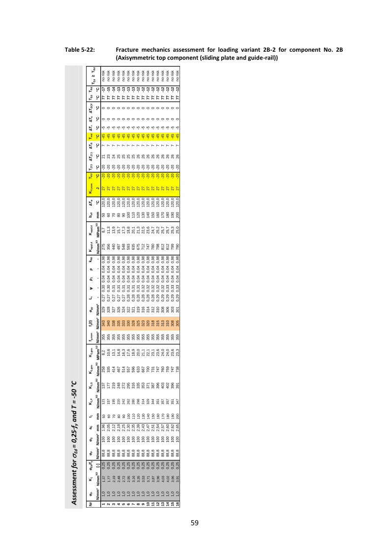
59
Table 5-22: Fracture mechanics assessment for loading variant 2B-2 for component No. 2B (Axisymmetric top component (sliding plate and guide-rail))
Ass
essm
ent
for
Ed =
0,2
5∙f
y a
nd
T =
-50
°C
Nr
P
K1
Ed
/f y
P
Sa 0
t 1K
1,P
K1,
SK
1,ge
sK
1,ge
sf y,
nom
f y(t)
gy
L r
1
k R
6K
appl
,d
Kap
pl,d
b e
ff
T
KV,
nom
T KV
T 27J
T 2
7J
T R
T md
T r
T
T DC
FT E
dT R
d
N/m
m²
N/m
m3/
2[-]
N/m
m²
N/m
m²
mm
mm
N/m
m3/
2N
/mm
3/2
N/m
m3/
2M
Pam
1/2
N/m
m²
N/m
m²
N/m
m²
- -
- -
-N
/mm
3/2
MPa
m1/
2m
m°C
J°C
°C°C
°C°C
°C°C
°C°C
°C1
1,0
1,37
0,25
88,8
100
1,96
5012
113
725
88,
235
534
332
90,
270,
300,
040,
040,
9827
58,
750
120,
027
-20
-20
217
-45
-50
077
-17
21,
01,
770,
2588
,810
02,
0560
157
177
335
10,6
355
340
328
0,27
0,30
0,04
0,04
0,98
356
11,3
6012
0,0
27-2
0-2
023
7-4
5-5
00
77-1
53
1,0
2,19
0,25
88,8
100
2,12
7019
521
941
413
,135
533
832
70,
270,
310,
040,
040,
9844
013
,970
120,
027
-20
-20
247
-45
-50
077
-14
41,
02,
480,
2588
,810
02,
1980
220
248
467
14,8
355
335
326
0,27
0,31
0,04
0,04
0,98
497
15,7
8012
0,0
27-2
0-2
025
7-4
5-5
00
77-1
35
1,0
2,72
0,25
88,8
100
2,25
9024
227
251
416
,335
533
332
40,
270,
310,
040,
040,
9854
817
,390
120,
027
-20
-20
257
-45
-50
077
-13
61,
02,
950,
2588
,810
02,
3010
026
229
555
717
,635
533
032
20,
280,
310,
040,
040,
9859
318
,810
012
0,0
27-2
0-2
025
7-4
5-5
00
77-1
37
1,0
3,16
0,25
88,8
100
2,35
110
280
316
596
18,9
355
328
321
0,28
0,31
0,04
0,04
0,98
635
20,1
110
120,
027
-20
-20
257
-45
-50
077
-13
81,
03,
350,
2588
,810
02,
3912
029
833
563
320
,035
532
531
90,
280,
310,
040,
040,
9867
521
,312
012
0,0
27-2
0-2
026
7-4
5-5
00
77-1
29
1,0
3,53
0,25
88,8
100
2,43
130
314
353
667
21,1
355
323
316
0,28
0,32
0,04
0,04
0,98
712
22,5
130
120,
027
-20
-20
267
-45
-50
077
-12
101,
03,
710,
2588
,810
02,
4714
032
937
170
022
,135
532
031
40,
280,
320,
040,
040,
9874
723
,614
012
0,0
27-2
0-2
026
7-4
5-5
00
77-1
211
1,0
3,87
0,25
88,8
100
2,51
150
344
387
731
23,1
355
318
312
0,28
0,32
0,04
0,04
0,98
780
24,7
150
120,
027
-20
-20
267
-45
-50
077
-12
121,
03,
960,
2588
,810
02,
5416
035
139
674
723
,635
531
531
00,
290,
320,
040,
040,
9879
825
,216
012
0,0
27-2
0-2
026
7-4
5-5
00
77-1
213
1,0
4,03
0,25
88,8
100
2,57
170
357
403
760
24,0
355
313
308
0,29
0,32
0,04
0,04
0,98
812
25,7
170
120,
027
-20
-20
267
-45
-50
077
-12
141,
04,
020,
2588
,810
02,
6018
035
740
275
924
,035
531
030
60,
290,
330,
040,
040,
9881
225
,718
012
0,0
27-2
0-2
026
7-4
5-5
00
77-1
215
1,0
3,96
0,25
88,8
100
2,62
190
351
396
747
23,6
355
308
303
0,29
0,33
0,04
0,04
0,98
799
25,3
190
120,
027
-20
-20
267
-45
-50
077
-12
161,
03,
910,
2588
,810
02,
6520
034
739
173
823
,335
530
530
10,
290,
330,
040,
040,
9879
025
,020
012
0,0
27-2
0-2
026
7-4
5-5
00
77-1
2no
risk
no ri
sk
T Ed
≥ T
Rd
no ri
skno
risk
no ri
skno
risk
no ri
skno
risk
no ri
sk
no ri
skno
risk
no ri
sk
no ri
skno
risk
no ri
skno
risk
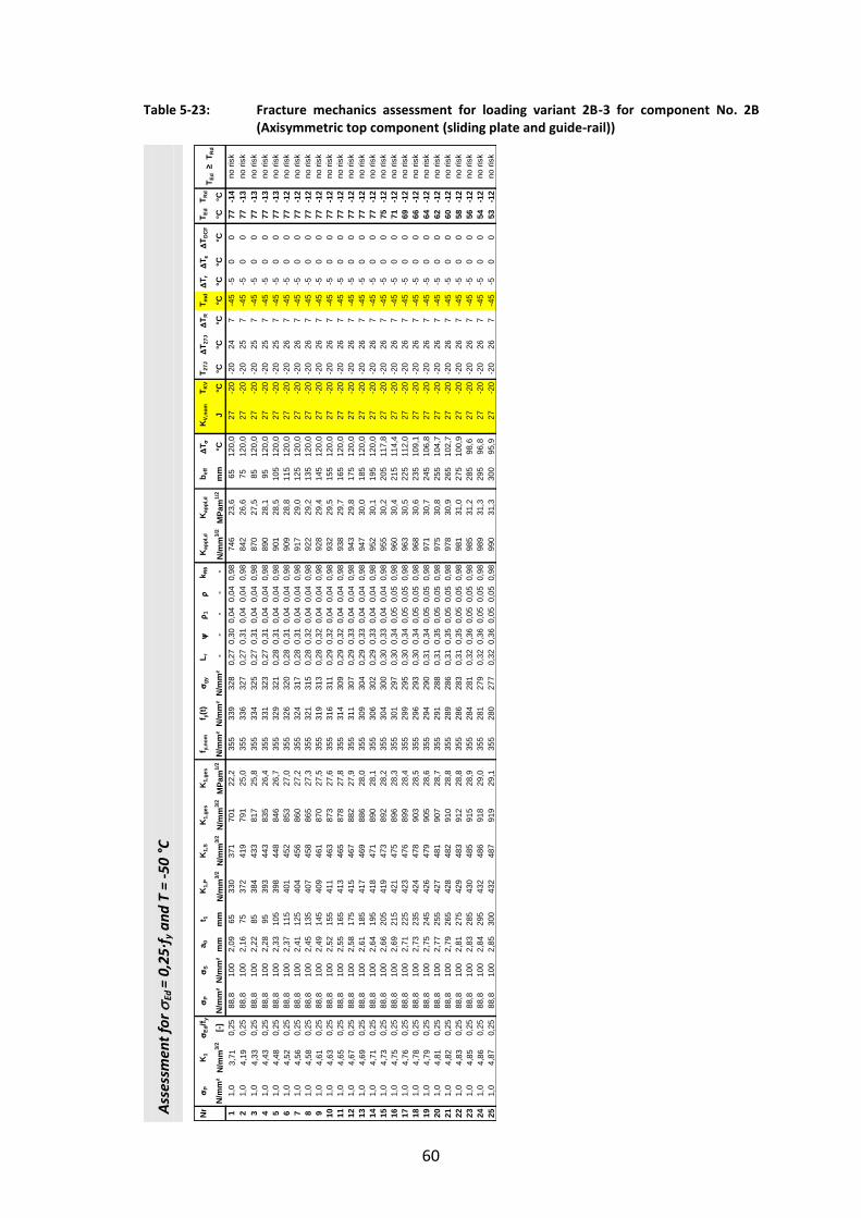
60
Table 5-23: Fracture mechanics assessment for loading variant 2B-3 for component No. 2B (Axisymmetric top component (sliding plate and guide-rail))
Ass
essm
ent
for
Ed =
0,2
5∙f
y a
nd
T =
-50
°C
Nr
P
K1
Ed
/f y
P
Sa 0
t 1K
1,P
K1,
SK
1,ge
sK
1,ge
sf y,
nom
f y(t)
gy
L r
1
k R
6K
appl
,d
Kap
pl,d
b e
ff
T
KV,
nom
T KV
T 27J
T 2
7J
T R
T md
T r
T
T DC
FT E
dT R
d
N/m
m²
N/m
m3/
2[-]
N/m
m²
N/m
m²
mm
mm
N/m
m3/
2N
/mm
3/2
N/m
m3/
2M
Pam
1/2
N/m
m²
N/m
m²
N/m
m²
- -
- -
-N
/mm
3/2
MPa
m1/
2m
m°C
J°C
°C°C
°C°C
°C°C
°C°C
°C1
1,0
3,71
0,25
88,8
100
2,09
6533
037
170
122
,235
533
932
80,
270,
300,
040,
040,
9874
623
,665
120,
027
-20
-20
247
-45
-50
077
-14
21,
04,
190,
2588
,810
02,
1675
372
419
791
25,0
355
336
327
0,27
0,31
0,04
0,04
0,98
842
26,6
7512
0,0
27-2
0-2
025
7-4
5-5
00
77-1
33
1,0
4,33
0,25
88,8
100
2,22
8538
443
381
725
,835
533
432
50,
270,
310,
040,
040,
9887
027
,585
120,
027
-20
-20
257
-45
-50
077
-13
41,
04,
430,
2588
,810
02,
2895
393
443
835
26,4
355
331
323
0,27
0,31
0,04
0,04
0,98
890
28,1
9512
0,0
27-2
0-2
025
7-4
5-5
00
77-1
35
1,0
4,48
0,25
88,8
100
2,33
105
398
448
846
26,7
355
329
321
0,28
0,31
0,04
0,04
0,98
901
28,5
105
120,
027
-20
-20
257
-45
-50
077
-13
61,
04,
520,
2588
,810
02,
3711
540
145
285
327
,035
532
632
00,
280,
310,
040,
040,
9890
928
,811
512
0,0
27-2
0-2
026
7-4
5-5
00
77-1
27
1,0
4,56
0,25
88,8
100
2,41
125
404
456
860
27,2
355
324
317
0,28
0,31
0,04
0,04
0,98
917
29,0
125
120,
027
-20
-20
267
-45
-50
077
-12
81,
04,
580,
2588
,810
02,
4513
540
745
886
527
,335
532
131
50,
280,
320,
040,
040,
9892
229
,213
512
0,0
27-2
0-2
026
7-4
5-5
00
77-1
29
1,0
4,61
0,25
88,8
100
2,49
145
409
461
870
27,5
355
319
313
0,28
0,32
0,04
0,04
0,98
928
29,4
145
120,
027
-20
-20
267
-45
-50
077
-12
101,
04,
630,
2588
,810
02,
5215
541
146
387
327
,635
531
631
10,
290,
320,
040,
040,
9893
229
,515
512
0,0
27-2
0-2
026
7-4
5-5
00
77-1
211
1,0
4,65
0,25
88,8
100
2,55
165
413
465
878
27,8
355
314
309
0,29
0,32
0,04
0,04
0,98
938
29,7
165
120,
027
-20
-20
267
-45
-50
077
-12
121,
04,
670,
2588
,810
02,
5817
541
546
788
227
,935
531
130
70,
290,
330,
040,
040,
9894
329
,817
512
0,0
27-2
0-2
026
7-4
5-5
00
77-1
213
1,0
4,69
0,25
88,8
100
2,61
185
417
469
886
28,0
355
309
304
0,29
0,33
0,04
0,04
0,98
947
30,0
185
120,
027
-20
-20
267
-45
-50
077
-12
141,
04,
710,
2588
,810
02,
6419
541
847
189
028
,135
530
630
20,
290,
330,
040,
040,
9895
230
,119
512
0,0
27-2
0-2
026
7-4
5-5
00
77-1
215
1,0
4,73
0,25
88,8
100
2,66
205
419
473
892
28,2
355
304
300
0,30
0,33
0,04
0,04
0,98
955
30,2
205
117,
827
-20
-20
267
-45
-50
075
-12
161,
04,
750,
2588
,810
02,
6921
542
147
589
628
,335
530
129
70,
300,
340,
050,
050,
9896
030
,421
511
4,4
27-2
0-2
026
7-4
5-5
00
71-1
217
1,0
4,76
0,25
88,8
100
2,71
225
423
476
899
28,4
355
299
295
0,30
0,34
0,05
0,05
0,98
963
30,5
225
112,
027
-20
-20
267
-45
-50
069
-12
181,
04,
780,
2588
,810
02,
7323
542
447
890
328
,535
529
629
30,
300,
340,
050,
050,
9896
830
,623
510
9,1
27-2
0-2
026
7-4
5-5
00
66-1
219
1,0
4,79
0,25
88,8
100
2,75
245
426
479
905
28,6
355
294
290
0,31
0,34
0,05
0,05
0,98
971
30,7
245
106,
827
-20
-20
267
-45
-50
064
-12
201,
04,
810,
2588
,810
02,
7725
542
748
190
728
,735
529
128
80,
310,
350,
050,
050,
9897
530
,825
510
4,7
27-2
0-2
026
7-4
5-5
00
62-1
221
1,0
4,82
0,25
88,8
100
2,79
265
428
482
910
28,8
355
289
286
0,31
0,35
0,05
0,05
0,98
978
30,9
265
102,
727
-20
-20
267
-45
-50
060
-12
221,
04,
830,
2588
,810
02,
8127
542
948
391
228
,835
528
628
30,
310,
350,
050,
050,
9898
131
,027
510
0,9
27-2
0-2
026
7-4
5-5
00
58-1
223
1,0
4,85
0,25
88,8
100
2,83
285
430
485
915
28,9
355
284
281
0,32
0,36
0,05
0,05
0,98
985
31,2
285
98,6
27-2
0-2
026
7-4
5-5
00
56-1
224
1,0
4,86
0,25
88,8
100
2,84
295
432
486
918
29,0
355
281
279
0,32
0,36
0,05
0,05
0,98
989
31,3
295
96,8
27-2
0-2
026
7-4
5-5
00
54-1
225
1,0
4,87
0,25
88,8
100
2,85
300
432
487
919
29,1
355
280
277
0,32
0,36
0,05
0,05
0,98
990
31,3
300
95,9
27-2
0-2
026
7-4
5-5
00
53-1
2no
risk
no ri
sk
no ri
skno
risk
no ri
skno
risk
no ri
skno
risk
no ri
skno
risk
no ri
skno
risk
no ri
skno
risk
no ri
skno
risk
no ri
skno
risk
no ri
skno
risk
no ri
sk
T Ed
≥ T
Rd
no ri
skno
risk
no ri
skno
risk

61
Table 5-24: Fracture mechanics assessment for loading variant 2B-4 for component No. 2B (Axisymmetric top component (sliding plate and guide-rail))
Ass
essm
ent
for
Ed =
0,2
5∙f
y a
nd
T =
-50
°C
Nr
P
K1
Ed
/f y
P
Sa 0
t 1K
1,P
K1,
SK
1,ge
sK
1,ge
sf y,
nom
f y(t)
gy
L r
1
k R
6K
appl
,d
Kap
pl,d
b e
ff
T
KV,
nom
T KV
T 27J
T 2
7J
T R
T md
T r
T
T DC
FT E
dT R
d
N/m
m²
N/m
m3/
2[-]
N/m
m²
N/m
m²
mm
mm
N/m
m3/
2N
/mm
3/2
N/m
m3/
2M
Pam
1/2
N/m
m²
N/m
m²
N/m
m²
- -
- -
-N
/mm
3/2
MPa
m1/
2m
m°C
J°C
°C°C
°C°C
°C°C
°C°C
°C1
1,0
2,24
00,
2588
,810
02,
0965
199
224
423
13,4
355
339
328
0,27
0,30
0,04
0,04
0,98
450
14,2
6512
0,0
27-2
0-2
024
7-4
5-5
00
77-1
42
1,0
2,23
70,
2588
,810
02,
1675
199
224
422
13,4
355
336
327
0,27
0,31
0,04
0,04
0,98
449
14,2
7512
0,0
27-2
0-2
025
7-4
5-5
00
77-1
33
1,0
2,22
10,
2588
,810
02,
2285
197
222
419
13,3
355
334
325
0,27
0,31
0,04
0,04
0,98
446
14,1
8512
0,0
27-2
0-2
025
7-4
5-5
00
77-1
34
1,0
2,31
90,
2588
,810
02,
2895
206
232
438
13,8
355
331
323
0,27
0,31
0,04
0,04
0,98
466
14,7
9512
0,0
27-2
0-2
025
7-4
5-5
00
77-1
35
1,0
2,58
40,
2588
,810
02,
3310
522
925
848
815
,435
532
932
10,
280,
310,
040,
040,
9852
016
,410
512
0,0
27-2
0-2
025
7-4
5-5
00
77-1
36
1,0
2,84
80,
2588
,810
02,
3711
525
328
553
717
,035
532
632
00,
280,
310,
040,
040,
9857
318
,111
512
0,0
27-2
0-2
026
7-4
5-5
00
77-1
27
1,0
3,08
30,
2588
,810
02,
4112
527
430
858
218
,435
532
431
70,
280,
310,
040,
040,
9862
019
,612
512
0,0
27-2
0-2
026
7-4
5-5
00
77-1
28
1,0
3,25
80,
2588
,810
02,
4513
528
932
661
519
,435
532
131
50,
280,
320,
040,
040,
9865
620
,713
512
0,0
27-2
0-2
026
7-4
5-5
00
77-1
29
1,0
3,46
80,
2588
,810
02,
4914
530
834
765
520
,735
531
931
30,
280,
320,
040,
040,
9869
922
,114
512
0,0
27-2
0-2
026
7-4
5-5
00
77-1
210
1,0
3,66
50,
2588
,810
02,
5215
532
536
769
221
,935
531
631
10,
290,
320,
040,
040,
9873
923
,415
512
0,0
27-2
0-2
026
7-4
5-5
00
77-1
211
1,0
3,80
40,
2588
,810
02,
5516
533
838
071
822
,735
531
430
90,
290,
320,
040,
040,
9876
724
,316
512
0,0
27-2
0-2
026
7-4
5-5
00
77-1
212
1,0
3,84
70,
2588
,810
02,
5817
534
138
572
623
,035
531
130
70,
290,
330,
040,
040,
9877
624
,517
512
0,0
27-2
0-2
026
7-4
5-5
00
77-1
213
1,0
3,85
00,
2588
,810
02,
6118
534
238
572
723
,035
530
930
40,
290,
330,
040,
040,
9877
724
,618
512
0,0
27-2
0-2
026
7-4
5-5
00
77-1
214
1,0
3,75
50,
2588
,810
02,
6419
533
337
670
922
,435
530
630
20,
290,
330,
040,
040,
9875
824
,019
512
0,0
27-2
0-2
026
7-4
5-5
00
77-1
215
1,0
3,64
90,
2588
,810
02,
6620
532
436
568
921
,835
530
430
00,
300,
330,
040,
040,
9873
723
,320
512
0,0
27-2
0-2
026
7-4
5-5
00
77-1
216
1,0
3,58
30,
2588
,810
02,
6921
531
835
867
621
,435
530
129
70,
300,
340,
050,
050,
9872
522
,921
512
0,0
27-2
0-2
026
7-4
5-5
00
77-1
217
1,0
3,51
00,
2588
,810
02,
7122
531
135
166
220
,935
529
929
50,
300,
340,
050,
050,
9871
022
,522
512
0,0
27-2
0-2
026
7-4
5-5
00
77-1
218
1,0
3,49
20,
2588
,810
02,
7323
531
034
965
920
,835
529
629
30,
300,
340,
050,
050,
9870
722
,423
512
0,0
27-2
0-2
026
7-4
5-5
00
77-1
219
1,0
3,43
90,
2588
,810
02,
7524
530
534
464
920
,535
529
429
00,
310,
340,
050,
050,
9869
722
,024
512
0,0
27-2
0-2
026
7-4
5-5
00
77-1
220
1,0
3,44
70,
2588
,810
02,
7725
530
634
565
120
,635
529
128
80,
310,
350,
050,
050,
9869
922
,125
512
0,0
27-2
0-2
026
7-4
5-5
00
77-1
221
1,0
3,42
20,
2588
,810
02,
7926
530
434
264
620
,435
528
928
60,
310,
350,
050,
050,
9869
422
,026
512
0,0
27-2
0-2
026
7-4
5-5
00
77-1
222
1,0
3,39
80,
2588
,810
02,
8127
530
234
064
120
,335
528
628
30,
310,
350,
050,
050,
9869
021
,827
512
0,0
27-2
0-2
026
7-4
5-5
00
77-1
223
1,0
3,38
90,
2588
,810
02,
8328
530
133
964
020
,235
528
428
10,
320,
360,
050,
050,
9868
921
,828
512
0,0
27-2
0-2
026
7-4
5-5
00
77-1
224
1,0
3,37
10,
2588
,810
02,
8429
529
933
763
620
,135
528
127
90,
320,
360,
050,
050,
9868
521
,729
512
0,0
27-2
0-2
026
7-4
5-5
00
77-1
225
1,0
3,35
90,
2588
,810
02,
8530
029
833
663
420
,035
528
027
70,
320,
360,
050,
050,
9868
321
,630
012
0,0
27-2
0-2
026
7-4
5-5
00
77-1
2
no ri
skno
risk
T Ed
≥ T
Rd
no ri
skno
risk
no ri
skno
risk
no ri
skno
risk
no ri
skno
risk
no ri
sk
no ri
skno
risk
no ri
skno
risk
no ri
skno
risk
no ri
sk
no ri
skno
risk
no ri
sk
no ri
sk
no ri
sk
no ri
skno
risk
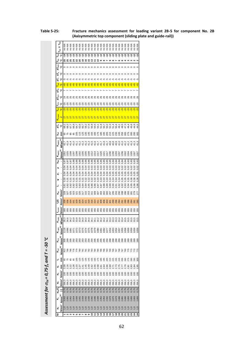
62
Table 5-25: Fracture mechanics assessment for loading variant 2B-5 for component No. 2B (Axisymmetric top component (sliding plate and guide-rail))
Ass
essm
ent
for
Ed =
0,7
5∙f
y a
nd
T =
-50
°C
Nr
P
K1
Ed
/f y
P
Sa 0
t 1K
1,P
K1,
SK
1,ge
sK
1,ge
sf y,
nom
f y(t)
gy
L r
1
k R
6K
appl
,d
Kap
pl,d
b e
ff
T
KV,
nom
T KV
T 27J
T 2
7J
T R
T md
T r
T
T DC
FT E
dT R
d
N/m
m²
N/m
m3/
2[-]
N/m
m²
N/m
m²
mm
mm
N/m
m3/
2N
/mm
3/2
N/m
m3/
2M
Pam
1/2
N/m
m²
N/m
m²
N/m
m²
- -
- -
-N
/mm
3/2
MPa
m1/
2m
m°C
J°C
°C°C
°C°C
°C°C
°C°C
°C1
1,0
3,05
20,
7526
6,3
100
2,09
6581
330
511
1835
,335
533
932
80,
810,
300,
040,
040,
8713
5242
,765
68,2
27-2
0-2
024
7-4
5-5
00
25-1
42
1,0
2,99
10,
7526
6,3
100
2,16
7579
629
910
9634
,635
533
632
70,
820,
310,
040,
040,
8713
2541
,975
68,3
27-2
0-2
025
7-4
5-5
00
25-1
33
1,0
2,95
20,
7526
6,3
100
2,22
8578
629
510
8134
,235
533
432
50,
820,
310,
040,
040,
8713
0841
,485
67,7
27-2
0-2
025
7-4
5-5
00
25-1
34
1,0
2,92
40,
7526
6,3
100
2,28
9577
829
210
7133
,935
533
132
30,
820,
310,
040,
040,
8612
9741
,095
66,9
27-2
0-2
025
7-4
5-5
00
24-1
35
1,0
2,92
60,
7526
6,3
100
2,33
105
779
293
1072
33,9
355
329
321
0,83
0,31
0,04
0,04
0,86
1299
41,1
105
64,7
27-2
0-2
025
7-4
5-5
00
22-1
36
1,0
2,93
10,
7526
6,3
100
2,37
115
780
293
1073
33,9
355
326
320
0,83
0,31
0,04
0,04
0,86
1302
41,2
115
62,6
27-2
0-2
026
7-4
5-5
00
20-1
27
1,0
2,93
40,
7526
6,3
100
2,41
125
781
293
1075
34,0
355
324
317
0,84
0,31
0,04
0,04
0,86
1305
41,3
125
60,7
27-2
0-2
026
7-4
5-5
00
18-1
28
1,0
2,93
20,
7526
6,3
100
2,45
135
781
293
1074
34,0
355
321
315
0,84
0,32
0,04
0,04
0,86
1305
41,3
135
59,2
27-2
0-2
026
7-4
5-5
00
16-1
29
1,0
2,93
60,
7526
6,3
100
2,49
145
782
294
1075
34,0
355
319
313
0,85
0,32
0,04
0,03
0,86
1308
41,3
145
57,6
27-2
0-2
026
7-4
5-5
00
15-1
210
1,0
2,94
20,
7526
6,3
100
2,52
155
783
294
1078
34,1
355
316
311
0,86
0,32
0,04
0,03
0,86
1312
41,5
155
55,9
27-2
0-2
026
7-4
5-5
00
13-1
211
1,0
2,94
60,
7526
6,3
100
2,55
165
784
295
1079
34,1
355
314
309
0,86
0,32
0,04
0,03
0,85
1314
41,6
165
54,5
27-2
0-2
026
7-4
5-5
00
11-1
212
1,0
2,94
90,
7526
6,3
100
2,58
175
785
295
1080
34,2
355
311
307
0,87
0,33
0,04
0,03
0,85
1317
41,7
175
53,1
27-2
0-2
026
7-4
5-5
00
10-1
213
1,0
2,95
20,
7526
6,3
100
2,61
185
786
295
1081
34,2
355
309
304
0,87
0,33
0,04
0,03
0,85
1320
41,7
185
51,8
27-2
0-2
026
7-4
5-5
00
9-1
214
1,0
2,95
30,
7526
6,3
100
2,64
195
786
295
1082
34,2
355
306
302
0,88
0,33
0,04
0,03
0,85
1321
41,8
195
50,7
27-2
0-2
026
7-4
5-5
00
8-1
215
1,0
2,94
20,
7526
6,3
100
2,66
205
783
294
1077
34,1
355
304
300
0,89
0,33
0,04
0,03
0,85
1317
41,7
205
50,2
27-2
0-2
026
7-4
5-5
00
7-1
216
1,0
2,87
80,
7526
6,3
100
2,69
215
766
288
1054
33,3
355
301
297
0,89
0,34
0,05
0,03
0,85
1290
40,8
215
52,3
27-2
0-2
026
7-4
5-5
00
9-1
217
1,0
2,87
50,
7526
6,3
100
2,71
225
766
288
1053
33,3
355
299
295
0,90
0,34
0,05
0,03
0,84
1290
40,8
225
51,4
27-2
0-2
026
7-4
5-5
00
8-1
218
1,0
2,87
90,
7526
6,3
100
2,73
235
767
288
1054
33,3
355
296
293
0,91
0,34
0,05
0,03
0,84
1293
40,9
235
50,4
27-2
0-2
026
7-4
5-5
00
7-1
219
1,0
2,88
60,
7526
6,3
100
2,75
245
768
289
1057
33,4
355
294
290
0,92
0,34
0,05
0,02
0,84
1297
41,0
245
49,1
27-2
0-2
026
7-4
5-5
00
6-1
220
1,0
2,88
10,
7526
6,3
100
2,77
255
767
288
1055
33,4
355
291
288
0,92
0,35
0,05
0,02
0,84
1296
41,0
255
48,5
27-2
0-2
026
7-4
5-5
00
6-1
221
1,0
2,89
00,
7526
6,3
100
2,79
265
769
289
1058
33,5
355
289
286
0,93
0,35
0,05
0,02
0,84
1302
41,2
265
47,3
27-2
0-2
026
7-4
5-5
00
4-1
222
1,0
2,89
30,
7526
6,3
100
2,81
275
770
289
1059
33,5
355
286
283
0,94
0,35
0,05
0,02
0,83
1304
41,2
275
46,4
27-2
0-2
026
7-4
5-5
00
3-1
223
1,0
2,89
30,
7526
6,3
100
2,83
285
770
289
1059
33,5
355
284
281
0,95
0,36
0,05
0,02
0,83
1305
41,3
285
45,6
27-2
0-2
026
7-4
5-5
00
3-1
224
1,0
2,89
30,
7526
6,3
100
2,84
295
770
289
1059
33,5
355
281
279
0,96
0,36
0,05
0,02
0,83
1307
41,3
295
44,9
27-2
0-2
026
7-4
5-5
00
2-1
224
1,0
2,89
30,
7526
6,3
100
2,85
300
770
289
1059
33,5
355
280
277
0,96
0,36
0,05
0,02
0,83
1307
41,3
300
44,5
27-2
0-2
026
7-4
5-5
00
2-1
2
T Ed
≥ T
Rd
no ri
skno
risk
no ri
sk
no ri
skno
risk
no ri
skno
risk
no ri
skno
risk
no ri
skno
risk
no ri
skno
risk
no ri
skno
risk
no ri
skno
risk
no ri
skno
risk
no ri
skno
risk
no ri
skno
risk
no ri
skno
risk
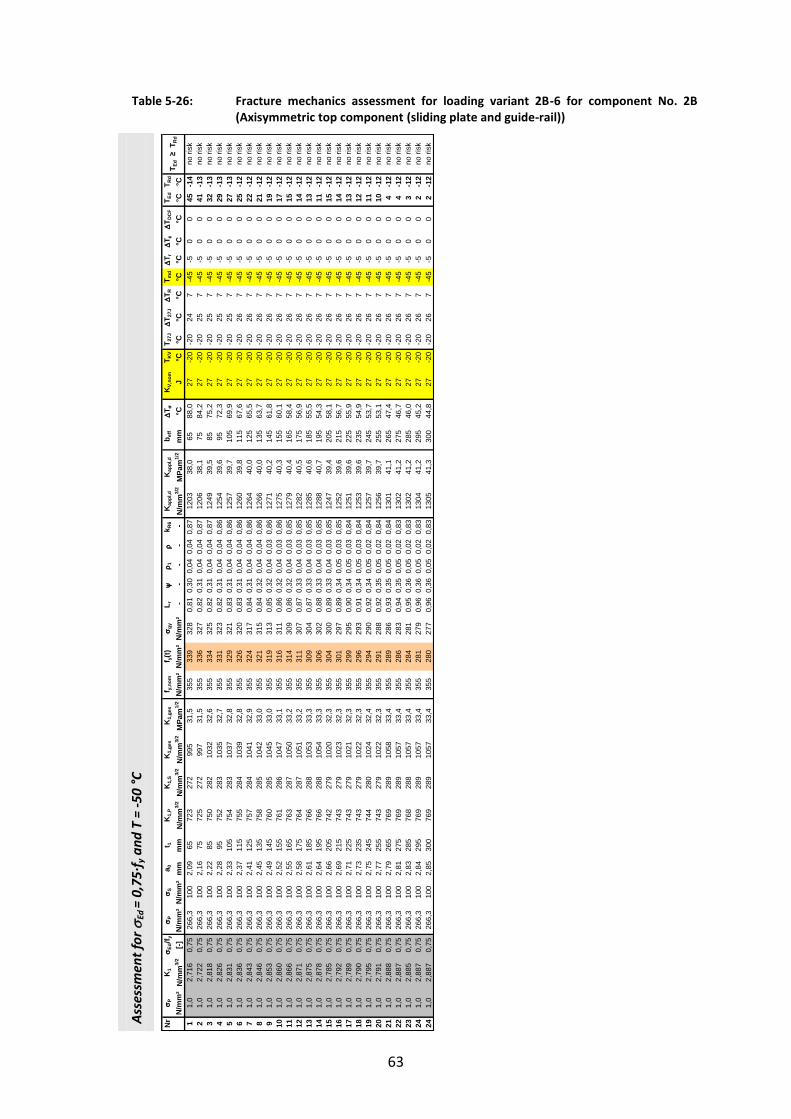
63
Table 5-26: Fracture mechanics assessment for loading variant 2B-6 for component No. 2B (Axisymmetric top component (sliding plate and guide-rail))
Ass
essm
ent
for
Ed =
0,7
5∙f
y a
nd
T =
-50
°C
Nr
P
K1
Ed
/f y
P
Sa 0
t 1K
1,P
K1,
SK
1,ge
sK
1,ge
sf y,
nom
f y(t)
gy
L r
1
k R
6K
appl
,d
Kap
pl,d
b e
ff
T
KV,
nom
T KV
T 27J
T 2
7J
T R
T md
T r
T
T DC
FT E
dT R
d
N/m
m²
N/m
m3/
2[-]
N/m
m²
N/m
m²
mm
mm
N/m
m3/
2N
/mm
3/2
N/m
m3/
2M
Pam
1/2
N/m
m²
N/m
m²
N/m
m²
- -
- -
-N
/mm
3/2
MPa
m1/
2m
m°C
J°C
°C°C
°C°C
°C°C
°C°C
°C1
1,0
2,71
60,
7526
6,3
100
2,09
6572
327
299
531
,535
533
932
80,
810,
300,
040,
040,
8712
0338
,065
88,0
27-2
0-2
024
7-4
5-5
00
45-1
42
1,0
2,72
20,
7526
6,3
100
2,16
7572
527
299
731
,535
533
632
70,
820,
310,
040,
040,
8712
0638
,175
84,2
27-2
0-2
025
7-4
5-5
00
41-1
33
1,0
2,81
80,
7526
6,3
100
2,22
8575
028
210
3232
,635
533
432
50,
820,
310,
040,
040,
8712
4939
,585
75,2
27-2
0-2
025
7-4
5-5
00
32-1
34
1,0
2,82
60,
7526
6,3
100
2,28
9575
228
310
3532
,735
533
132
30,
820,
310,
040,
040,
8612
5439
,695
72,3
27-2
0-2
025
7-4
5-5
00
29-1
35
1,0
2,83
10,
7526
6,3
100
2,33
105
754
283
1037
32,8
355
329
321
0,83
0,31
0,04
0,04
0,86
1257
39,7
105
69,9
27-2
0-2
025
7-4
5-5
00
27-1
36
1,0
2,83
60,
7526
6,3
100
2,37
115
755
284
1039
32,8
355
326
320
0,83
0,31
0,04
0,04
0,86
1260
39,8
115
67,6
27-2
0-2
026
7-4
5-5
00
25-1
27
1,0
2,84
30,
7526
6,3
100
2,41
125
757
284
1041
32,9
355
324
317
0,84
0,31
0,04
0,04
0,86
1264
40,0
125
65,5
27-2
0-2
026
7-4
5-5
00
22-1
28
1,0
2,84
60,
7526
6,3
100
2,45
135
758
285
1042
33,0
355
321
315
0,84
0,32
0,04
0,04
0,86
1266
40,0
135
63,7
27-2
0-2
026
7-4
5-5
00
21-1
29
1,0
2,85
30,
7526
6,3
100
2,49
145
760
285
1045
33,0
355
319
313
0,85
0,32
0,04
0,03
0,86
1271
40,2
145
61,8
27-2
0-2
026
7-4
5-5
00
19-1
210
1,0
2,86
00,
7526
6,3
100
2,52
155
761
286
1047
33,1
355
316
311
0,86
0,32
0,04
0,03
0,86
1275
40,3
155
60,1
27-2
0-2
026
7-4
5-5
00
17-1
211
1,0
2,86
60,
7526
6,3
100
2,55
165
763
287
1050
33,2
355
314
309
0,86
0,32
0,04
0,03
0,85
1279
40,4
165
58,4
27-2
0-2
026
7-4
5-5
00
15-1
212
1,0
2,87
10,
7526
6,3
100
2,58
175
764
287
1051
33,2
355
311
307
0,87
0,33
0,04
0,03
0,85
1282
40,5
175
56,9
27-2
0-2
026
7-4
5-5
00
14-1
213
1,0
2,87
50,
7526
6,3
100
2,61
185
766
288
1053
33,3
355
309
304
0,87
0,33
0,04
0,03
0,85
1285
40,6
185
55,5
27-2
0-2
026
7-4
5-5
00
13-1
214
1,0
2,87
80,
7526
6,3
100
2,64
195
766
288
1054
33,3
355
306
302
0,88
0,33
0,04
0,03
0,85
1288
40,7
195
54,3
27-2
0-2
026
7-4
5-5
00
11-1
215
1,0
2,78
50,
7526
6,3
100
2,66
205
742
279
1020
32,3
355
304
300
0,89
0,33
0,04
0,03
0,85
1247
39,4
205
58,1
27-2
0-2
026
7-4
5-5
00
15-1
216
1,0
2,79
20,
7526
6,3
100
2,69
215
743
279
1023
32,3
355
301
297
0,89
0,34
0,05
0,03
0,85
1252
39,6
215
56,7
27-2
0-2
026
7-4
5-5
00
14-1
217
1,0
2,78
90,
7526
6,3
100
2,71
225
743
279
1021
32,3
355
299
295
0,90
0,34
0,05
0,03
0,84
1251
39,6
225
55,9
27-2
0-2
026
7-4
5-5
00
13-1
218
1,0
2,79
00,
7526
6,3
100
2,73
235
743
279
1022
32,3
355
296
293
0,91
0,34
0,05
0,03
0,84
1253
39,6
235
54,9
27-2
0-2
026
7-4
5-5
00
12-1
219
1,0
2,79
50,
7526
6,3
100
2,75
245
744
280
1024
32,4
355
294
290
0,92
0,34
0,05
0,02
0,84
1257
39,7
245
53,7
27-2
0-2
026
7-4
5-5
00
11-1
220
1,0
2,79
10,
7526
6,3
100
2,77
255
743
279
1022
32,3
355
291
288
0,92
0,35
0,05
0,02
0,84
1256
39,7
255
53,1
27-2
0-2
026
7-4
5-5
00
10-1
221
1,0
2,88
80,
7526
6,3
100
2,79
265
769
289
1058
33,4
355
289
286
0,93
0,35
0,05
0,02
0,84
1301
41,1
265
47,4
27-2
0-2
026
7-4
5-5
00
4-1
222
1,0
2,88
70,
7526
6,3
100
2,81
275
769
289
1057
33,4
355
286
283
0,94
0,35
0,05
0,02
0,83
1302
41,2
275
46,7
27-2
0-2
026
7-4
5-5
00
4-1
223
1,0
2,88
50,
7526
6,3
100
2,83
285
768
288
1057
33,4
355
284
281
0,95
0,36
0,05
0,02
0,83
1302
41,2
285
46,0
27-2
0-2
026
7-4
5-5
00
3-1
224
1,0
2,88
70,
7526
6,3
100
2,84
295
769
289
1057
33,4
355
281
279
0,96
0,36
0,05
0,02
0,83
1304
41,2
295
45,2
27-2
0-2
026
7-4
5-5
00
2-1
224
1,0
2,88
70,
7526
6,3
100
2,85
300
769
289
1057
33,4
355
280
277
0,96
0,36
0,05
0,02
0,83
1305
41,3
300
44,8
27-2
0-2
026
7-4
5-5
00
2-1
2
T Ed
≥ T
Rd
no ri
sk
no ri
skno
risk
no ri
skno
risk
no ri
skno
risk
no ri
skno
risk
no ri
skno
risk
no ri
skno
risk
no ri
skno
risk
no ri
skno
risk
no ri
skno
risk
no ri
skno
risk
no ri
skno
risk
no ri
skno
risk
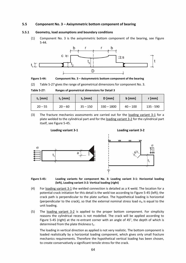
64
5.5 Component No. 3 – Axisymmetric bottom component of bearing
5.5.1 Geometry, load assumptions and boundary conditions
(1) Component No. 3 is the axisymmetric bottom component of the bearing, see Figure 5-44.
Figure 5-44: Component No. 3 – Axisymmetric bottom component of the bearing
(2) Table 5-27 gives the range of geometrical dimensions for component No. 3.
Table 5-27: Ranges of geometrical dimensions for Detail 3
t1 [mm] t2 [mm] t3 [mm] D [mm] b [mm] r [mm]
20 – 55 20 – 60 35 – 150 330 – 1800 40 – 100 135 - 590
(3) The fracture mechanics assessments are carried out for the loading variant 3-1 for a plate welded to the cylindrical part and for the loading variant 3-2 for the cylindrical part itself, see Figure 5-45.
Loading variant 3-1 Loading variant 3-2
Figure 5-45: Loading variants for component No. 3: Loading variant 3-1: Horizontal loading (left), Loading variant 3-2: Vertical loading (right)
(4) For loading variant 3-1 the welded connection is detailed as a K-weld. The location for a potential crack initiation for this detail is the weld toe according to Figure 5-45 (left); the crack path is perpendicular to the plate surface. The hypothetical loading is horizontal
(perpendicular to the crack), so that the external nominal stress load N is equal to the unit loading.
(5) The loading variant 3-2 is applied to the proper bottom component. For simplicity reasons the cylindrical recess is not modelled. The crack will be applied according to Figure 5-45 (right) at the re-entrant corner with an angle of 45°, the depth of which is determined from the plate thickness t2.
The loading in vertical direction as applied is not very realistic. The bottom component is loaded realistically by a horizontal loading component, which gives only small fracture mechanics requirements. Therefore the hypothetical vertical loading has been chosen, to create conservatively a significant tensile stress for the crack.

65
(6) The magnitude of the stress intensity factors for loading variant 3-1 depends only on the plate-thickness t1. Therefore only a single configuration is studied.
For the loading variant 3-2 the investigations are carried out for two bounds of geometrical dimensions, see Table 5-28, taking account of the influence of the width b+r of the cylindrical part. For the upper bound of geometrical dimensions the maximum value b+r = 690 mm was used, for the lower bound the minimum value at the lower bound b+r = 175 mm was chosen. As a consequence of the choice of vertical loading and for achieving the maximum bending moment at the crack-location assumed the width of the bottom component D was fixed with the maximum value D = 1800 mm.
Table 5-28: Upper and lower bounds of the geometrical dimensions for loading variant 3-2
Upper bounds Lower bounds
t2 [mm] 20 - 60 t2 [mm] 20 - 60
t3[mm] 150 t3 [mm] 150
D [mm] 1800 D [mm] 1800
b + r [mm] 690 b + r [mm] 175
(7) Figure 5-46 shows a section of the plot of deformations and the crack opening for the loading variants 3-1 and 3-2 from the FE-model.
Loading variant 3-1 Loading variant 3-2
Figure 5-46: Section of plot with deformations and crack opening for loading variant 3-1: welded plate to the bottom component (left) and for loading variant 3-2: cylindrical part of the bottom component (right)
5.5.2 Hot-Spot stresses
(1) The stresses HS necessary for the fracture mechanics assessment are calculated for loading variant 3-1 according to the bending theory.
(2) The nominal stress Ed is equal to HS and corresponds to the external stress loading applied to the FE-model.
(3) In Figure 5-47 (left) the distribution of the Hot-Spot-stresses for the upper bound of
geometrical dimensions is shown for loading variant 3-2. There is a decrease of HS converging to a small value.
Also the stress distribution as calculated from the bending theory is plotted, which is
qualitatively analogous however yields about double the stresses rather than HS for small values t2. The evaluation and the performance of the fracture mechanics assessment therefore is made with the Hot-Spot-stresses.
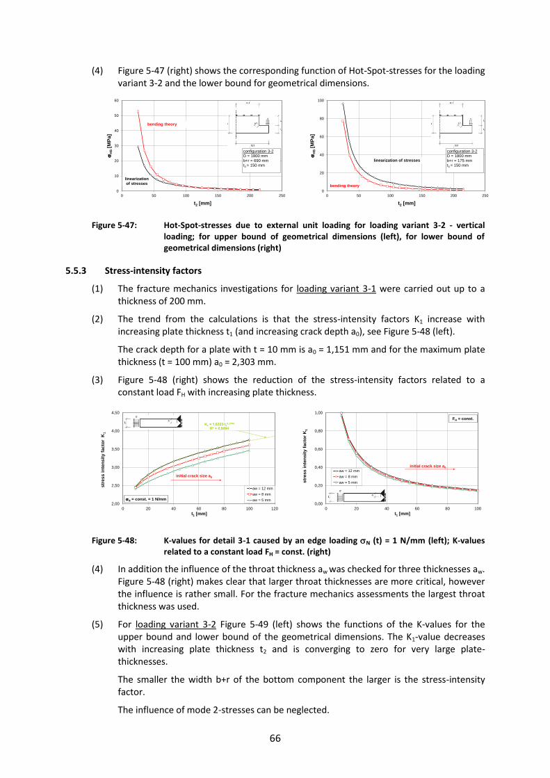
66
(4) Figure 5-47 (right) shows the corresponding function of Hot-Spot-stresses for the loading variant 3-2 and the lower bound for geometrical dimensions.
Figure 5-47: Hot-Spot-stresses due to external unit loading for loading variant 3-2 - vertical loading; for upper bound of geometrical dimensions (left), for lower bound of geometrical dimensions (right)
5.5.3 Stress-intensity factors
(1) The fracture mechanics investigations for loading variant 3-1 were carried out up to a thickness of 200 mm.
(2) The trend from the calculations is that the stress-intensity factors K1 increase with increasing plate thickness t1 (and increasing crack depth a0), see Figure 5-48 (left).
The crack depth for a plate with t = 10 mm is a0 = 1,151 mm and for the maximum plate thickness (t = 100 mm) a0 = 2,303 mm.
(3) Figure 5-48 (right) shows the reduction of the stress-intensity factors related to a constant load FH with increasing plate thickness.
Figure 5-48: K-values for detail 3-1 caused by an edge loading N (t) = 1 N/mm (left); K-values related to a constant load FH = const. (right)
(4) In addition the influence of the throat thickness aw was checked for three thicknesses aw. Figure 5-48 (right) makes clear that larger throat thicknesses are more critical, however the influence is rather small. For the fracture mechanics assessments the largest throat thickness was used.
(5) For loading variant 3-2 Figure 5-49 (left) shows the functions of the K-values for the upper bound and lower bound of the geometrical dimensions. The K1-value decreases with increasing plate thickness t2 and is converging to zero for very large plate-thicknesses.
The smaller the width b+r of the bottom component the larger is the stress-intensity factor.
The influence of mode 2-stresses can be neglected.
0
10
20
30
40
50
60
0 50 100 150 200 250
H
S[M
Pa]
t2 [mm]
linearization of stresses
configuration 3-2D = 1800 mmb+r = 690 mmt3 = 150 mm
bending theory
0
20
40
60
80
100
0 50 100 150 200 250
H
S[M
Pa]
t2 [mm]
linearization of stresses
configuration 3-2D = 1800 mmb+r = 175 mmt3 = 150 mm
bending theory
K1 = 1,6323∙t10,1794
R2 = 0,9994
2,00
2,50
3,00
3,50
4,00
4,50
0 20 40 60 80 100 120
stre
ss in
tens
ity fa
ctor
K1
t1 [mm]
aw = 12 mmaw = 8 mmaw = 5 mmN = const. = 1 N/mm
initial crack size a0
0,00
0,20
0,40
0,60
0,80
1,00
0 20 40 60 80 100
stre
ss in
tens
ity fa
ctor
K1
t1 [mm]
aw = 12 mmaw = 8 mmaw = 5 mm
initial crack size a0
FH = const.

67
(6) The Figure 5-49 (right) gives the function of the normalized -values related to
HS = 1 N/mm² at the Hot-Spot. Apparently the relevant case for the fracture mechanics assessment is the case of lower bound of geometrical dimensions.
Figure 5-49: K-values for the loading variant 3-2 with variation of the plate thickness t2; K-values
for the unit-loading (left), -values related to HS= 1 N/mm² at the Hot-Spot (right)
(7) Figure 5-50 gives the effects of a variation of the thickness t3 of the bottom component of the bearing. The K-value is not influenced by t3. The relevant parameter for variation is the plate thickness t2 as presented in Figure 5-49.
Figure 5-50: K-values for the loading variant 3-2: variation of the plate thickness t3; K-values due to unit loading
5.5.4 Assessments to avoid brittle fracture
(1) The assessments to avoid brittle fracture are carried out for loading variant 3-1 in Table 5-31 and for loading variant 3-2 in Table 5-32.
(2) The results for which examples of the tabular calculations are given in Table 5-31 and Table 5-32 are presented in Table 5-29 and Table 5-30.
Table 5-29: Limits of plate thickness [mm] for the bottom component of the bearing (loading variant 3-1)
Steel grade acc. to EN 10025
Ed 0°C -10°C -20°C -30°C -40°C -50°C
S355J2 0,25 ∙ fy 250*) 250*) 250*) 250*) 250*) 250*)
S355J2 0,50 ∙ fy 250*) 250*) 250*) 250*) 250*) 250*)
S355J2 0,75 ∙ fy 250*) 250*) 250*) 200 140 110
*) Assumption of a technical manufacturing limit (in theory element thicknesses with t ≥ 250 mm would be acceptable)
0
50
100
150
200
250
0 50 100 150 200 250
stre
ss in
tens
ity fa
ctor
K1
t2 [mm]
t3=150, D=1800, b+r=690
t3=150, D=1800, b+r=175
b+r=690 mmb+r=175 mm
0
1
2
3
4
0 50 100 150 200 250
stre
ss in
tens
ity fa
ctor
K
t2 [mm]
t3=150, D=1800, b+r=690t3=150, D=1800, b+r=175
HS = 1N/mm²
initial crack size a0
b+r=690 mm
b+r=175 mm
0
20
40
60
80
100
0 50 100 150 200 250 300
stre
ss in
tens
ity fa
ctor
K1
t3 [mm]
t2=25, D=1800, b+r=690, e=210
t2=55, D=1800, b+r=690, e=210

68
Table 5-30: Limits of plate thickness [mm] for the bottom component of the bearing (loading variant 3-2)
Steel grade acc. to EN 10025
Ed 0°C -10°C -20°C -30°C -40°C -50°C
S355J2 0,25 ∙ fy 200*) 200*) 200*) 200*) 200*) 200*)
S355J2 0,50 ∙ fy 200*) 200*) 200*) 200*) 200*) 200*)
S355J2 0,75 ∙ fy 200*) 200*) 200*) 200*) 200*) 200*)
*) Assumption of a technical manufacturing limit (in theory element thicknesses with t ≥ 200 mm would be acceptable)

69
Table 5-31: Fracture mechanics assessment for loading variant 3-1 for component No. 3
Ass
essm
ent
for
Ed =
0,7
5∙f
y a
nd
T =
-30
°C
Ass
essm
ent
for
Ed =
0,7
5∙f
y a
nd
T =
-40
°C
Nr
P
K1
Ed
/f y
P
Sa 0
t 1K
1,P
K1,
SK
1,ge
sK
1,ge
sf y,
nom
f y(t)
gy
L r
1
k R
6K
appl
,d
Kap
pl,d
b e
ff
T
KV,
nom
T KV
T 27J
T 2
7J
T R
T md
T r
T
T DC
FT E
dT R
d
N/m
m²
N/m
m3/
2[-]
N/m
m²
N/m
m²
mm
mm
N/m
m3/
2N
/mm
3/2
N/m
m3/
2M
Pam
1/2
N/m
m²
N/m
m²
N/m
m²
- -
- -
-N
/mm
3/2
MPa
m1/
2m
m°C
J°C
°C°C
°C°C
°C°C
°C°C
°C1
1,0
2,46
20,
7526
6,3
100
1,15
1065
624
690
228
,535
535
331
20,
850,
320,
040,
030,
8610
9734
,710
120,
027
-20
-20
07
-25
-50
097
-38
21,
02,
661
0,75
266,
310
01,
3515
708
266
975
30,8
355
351
320
0,83
0,31
0,04
0,04
0,86
1182
37,4
1512
0,0
27-2
0-2
01
7-2
5-5
00
97-3
73
1,0
2,80
50,
7526
6,3
100
1,50
2074
728
110
2732
,535
535
032
40,
820,
310,
040,
040,
8612
4439
,320
110,
927
-20
-20
27
-25
-50
088
-36
41,
02,
917
0,75
266,
310
01,
6125
777
292
1068
33,8
355
349
326
0,82
0,31
0,04
0,04
0,87
1293
40,9
2596
,827
-20
-20
57
-25
-50
074
-33
51,
03,
008
0,75
266,
310
01,
7030
801
301
1102
34,8
355
348
328
0,81
0,31
0,04
0,04
0,87
1332
42,1
3086
,927
-20
-20
87
-25
-50
064
-30
61,
03,
087
0,75
266,
310
01,
7835
822
309
1131
35,8
355
346
329
0,81
0,30
0,04
0,04
0,87
1367
43,2
3579
,227
-20
-20
127
-25
-50
056
-26
71,
03,
158
0,75
266,
310
01,
8440
841
316
1157
36,6
355
345
329
0,81
0,30
0,04
0,04
0,87
1398
44,2
4072
,927
-20
-20
167
-25
-50
050
-22
81,
03,
222
0,75
266,
310
01,
9045
858
322
1180
37,3
355
344
329
0,81
0,30
0,04
0,04
0,87
1426
45,1
4567
,627
-20
-20
197
-25
-50
045
-19
91,
03,
282
0,75
266,
310
01,
9650
874
328
1202
38,0
355
343
329
0,81
0,30
0,04
0,04
0,87
1453
45,9
5063
,027
-20
-20
217
-25
-50
040
-17
101,
03,
339
0,75
266,
310
02,
0055
889
334
1223
38,7
355
341
329
0,81
0,30
0,04
0,04
0,87
1478
46,7
5558
,927
-20
-20
227
-25
-50
036
-16
111,
03,
392
0,75
266,
310
02,
0560
903
339
1242
39,3
355
340
328
0,81
0,30
0,04
0,04
0,87
1502
47,5
6055
,227
-20
-20
237
-25
-50
032
-15
121,
03,
442
0,75
266,
310
02,
0965
916
344
1261
39,9
355
339
328
0,81
0,30
0,04
0,04
0,87
1524
48,2
6551
,927
-20
-20
247
-25
-50
029
-14
131,
03,
491
0,75
266,
310
02,
1270
929
349
1279
40,4
355
338
327
0,81
0,31
0,04
0,04
0,87
1546
48,9
7048
,827
-20
-20
247
-25
-50
026
-14
141,
03,
538
0,75
266,
310
02,
1675
942
354
1296
41,0
355
336
327
0,82
0,31
0,04
0,04
0,87
1568
49,6
7546
,027
-20
-20
257
-25
-50
023
-13
151,
03,
583
0,75
266,
310
02,
1980
954
358
1312
41,5
355
335
326
0,82
0,31
0,04
0,04
0,87
1588
50,2
8043
,327
-20
-20
257
-25
-50
020
-13
161,
03,
626
0,75
266,
310
02,
2285
965
363
1328
42,0
355
334
325
0,82
0,31
0,04
0,04
0,87
1608
50,8
8540
,927
-20
-20
257
-25
-50
018
-13
171,
03,
668
0,75
266,
310
02,
2590
977
367
1343
42,5
355
333
324
0,82
0,31
0,04
0,04
0,86
1627
51,4
9038
,627
-20
-20
257
-25
-50
016
-13
181,
03,
709
0,75
266,
310
02,
2895
988
371
1358
43,0
355
331
323
0,82
0,31
0,04
0,04
0,86
1645
52,0
9536
,527
-20
-20
257
-25
-50
013
-13
191,
03,
749
0,75
266,
310
02,
3010
099
837
513
7343
,435
533
032
20,
830,
310,
040,
040,
8616
6452
,610
034
,427
-20
-20
257
-25
-50
011
-13
201,
04,
223
0,75
266,
310
02,
6520
011
2442
215
4748
,935
530
530
10,
880,
330,
040,
030,
8518
9059
,820
010
,827
-20
-20
267
-25
-50
0-1
2-1
2
no ri
skno
risk
T Ed
≥ T
Rd
no ri
skno
risk
no ri
sk
no ri
sk
no ri
sk
no ri
skno
risk
no ri
skno
risk
no ri
sk
no ri
skno
risk
no ri
sk
no ri
skno
risk
no ri
skno
risk
no ri
sk
Nr
P
K1
Ed
/f y
P
Sa 0
t 1K
1,P
K1,
SK
1,ge
sK
1,ge
sf y,
nom
f y(t)
gy
L r
1
k R
6K
appl
,d
Kap
pl,d
b e
ff
T
KV,
nom
T KV
T 27J
T 2
7J
T R
T md
T r
T
T DC
FT E
dT R
d
N/m
m²
N/m
m3/
2[-]
N/m
m²
N/m
m²
mm
mm
N/m
m3/
2N
/mm
3/2
N/m
m3/
2M
Pam
1/2
N/m
m²
N/m
m²
N/m
m²
- -
- -
-N
/mm
3/2
MPa
m1/
2m
m°C
J°C
°C°C
°C°C
°C°C
°C°C
°C1
1,0
2,46
20,
7526
6,3
100
1,15
1065
624
690
228
,535
535
331
20,
850,
320,
040,
030,
8610
9734
,710
120,
027
-20
-20
07
-35
-50
087
-38
21,
02,
661
0,75
266,
310
01,
3515
708
266
975
30,8
355
351
320
0,83
0,31
0,04
0,04
0,86
1182
37,4
1512
0,0
27-2
0-2
01
7-3
5-5
00
87-3
73
1,0
2,80
50,
7526
6,3
100
1,50
2074
728
110
2732
,535
535
032
40,
820,
310,
040,
040,
8612
4439
,320
110,
927
-20
-20
27
-35
-50
078
-36
41,
02,
917
0,75
266,
310
01,
6125
777
292
1068
33,8
355
349
326
0,82
0,31
0,04
0,04
0,87
1293
40,9
2596
,827
-20
-20
57
-35
-50
064
-33
51,
03,
008
0,75
266,
310
01,
7030
801
301
1102
34,8
355
348
328
0,81
0,31
0,04
0,04
0,87
1332
42,1
3086
,927
-20
-20
87
-35
-50
054
-30
61,
03,
087
0,75
266,
310
01,
7835
822
309
1131
35,8
355
346
329
0,81
0,30
0,04
0,04
0,87
1367
43,2
3579
,227
-20
-20
127
-35
-50
046
-26
71,
03,
158
0,75
266,
310
01,
8440
841
316
1157
36,6
355
345
329
0,81
0,30
0,04
0,04
0,87
1398
44,2
4072
,927
-20
-20
167
-35
-50
040
-22
81,
03,
222
0,75
266,
310
01,
9045
858
322
1180
37,3
355
344
329
0,81
0,30
0,04
0,04
0,87
1426
45,1
4567
,627
-20
-20
197
-35
-50
035
-19
91,
03,
282
0,75
266,
310
01,
9650
874
328
1202
38,0
355
343
329
0,81
0,30
0,04
0,04
0,87
1453
45,9
5063
,027
-20
-20
217
-35
-50
030
-17
101,
03,
339
0,75
266,
310
02,
0055
889
334
1223
38,7
355
341
329
0,81
0,30
0,04
0,04
0,87
1478
46,7
5558
,927
-20
-20
227
-35
-50
026
-16
111,
03,
392
0,75
266,
310
02,
0560
903
339
1242
39,3
355
340
328
0,81
0,30
0,04
0,04
0,87
1502
47,5
6055
,227
-20
-20
237
-35
-50
022
-15
121,
03,
442
0,75
266,
310
02,
0965
916
344
1261
39,9
355
339
328
0,81
0,30
0,04
0,04
0,87
1524
48,2
6551
,927
-20
-20
247
-35
-50
019
-14
131,
03,
491
0,75
266,
310
02,
1270
929
349
1279
40,4
355
338
327
0,81
0,31
0,04
0,04
0,87
1546
48,9
7048
,827
-20
-20
247
-35
-50
016
-14
141,
03,
538
0,75
266,
310
02,
1675
942
354
1296
41,0
355
336
327
0,82
0,31
0,04
0,04
0,87
1568
49,6
7546
,027
-20
-20
257
-35
-50
013
-13
151,
03,
583
0,75
266,
310
02,
1980
954
358
1312
41,5
355
335
326
0,82
0,31
0,04
0,04
0,87
1588
50,2
8043
,327
-20
-20
257
-35
-50
010
-13
161,
03,
626
0,75
266,
310
02,
2285
965
363
1328
42,0
355
334
325
0,82
0,31
0,04
0,04
0,87
1608
50,8
8540
,927
-20
-20
257
-35
-50
08
-13
171,
03,
668
0,75
266,
310
02,
2590
977
367
1343
42,5
355
333
324
0,82
0,31
0,04
0,04
0,86
1627
51,4
9038
,627
-20
-20
257
-35
-50
06
-13
181,
03,
709
0,75
266,
310
02,
2895
988
371
1358
43,0
355
331
323
0,82
0,31
0,04
0,04
0,86
1645
52,0
9536
,527
-20
-20
257
-35
-50
03
-13
191,
03,
749
0,75
266,
310
02,
3010
099
837
513
7343
,435
533
032
20,
830,
310,
040,
040,
8616
6452
,610
034
,427
-20
-20
257
-35
-50
01
-13
201,
03,
961
0,75
266,
310
02,
4714
010
5539
614
5145
,935
532
031
40,
850,
320,
040,
040,
8617
6455
,814
022
,927
-20
-20
267
-35
-50
0-1
0-1
2no
risk
no ri
skno
risk
no ri
sk
no ri
skno
risk
no ri
skno
risk
no ri
sk
no ri
skno
risk
no ri
skno
risk
no ri
sk
no ri
skno
risk
T Ed
≥ T
Rd
no ri
skno
risk
no ri
sk
no ri
sk

70
Table 5-31: Continued
Ass
essm
ent
for
Ed =
0,7
5∙f
y a
nd
T =
-50
°C
Nr
P
K1
Ed
/f y
P
Sa 0
t 1K
1,P
K1,
SK
1,ge
sK
1,ge
sf y,
nom
f y(t)
gy
L r
1
k R
6K
appl
,d
Kap
pl,d
b e
ff
T
KV,
nom
T KV
T 27J
T 2
7J
T R
T md
T r
T
T DC
FT E
dT R
d
N/m
m²
N/m
m3/
2[-]
N/m
m²
N/m
m²
mm
mm
N/m
m3/
2N
/mm
3/2
N/m
m3/
2M
Pam
1/2
N/m
m²
N/m
m²
N/m
m²
- -
- -
-N
/mm
3/2
MPa
m1/
2m
m°C
J°C
°C°C
°C°C
°C°C
°C°C
°C1
1,0
2,46
20,
7526
6,3
100
1,15
1065
624
690
228
,535
535
331
20,
850,
320,
040,
030,
8610
9734
,710
120,
027
-20
-20
07
-45
-50
077
-38
21,
02,
661
0,75
266,
310
01,
3515
708
266
975
30,8
355
351
320
0,83
0,31
0,04
0,04
0,86
1182
37,4
1512
0,0
27-2
0-2
01
7-4
5-5
00
77-3
73
1,0
2,80
50,
7526
6,3
100
1,50
2074
728
110
2732
,535
535
032
40,
820,
310,
040,
040,
8612
4439
,320
110,
927
-20
-20
27
-45
-50
068
-36
41,
02,
917
0,75
266,
310
01,
6125
777
292
1068
33,8
355
349
326
0,82
0,31
0,04
0,04
0,87
1293
40,9
2596
,827
-20
-20
57
-45
-50
054
-33
51,
03,
008
0,75
266,
310
01,
7030
801
301
1102
34,8
355
348
328
0,81
0,31
0,04
0,04
0,87
1332
42,1
3086
,927
-20
-20
87
-45
-50
044
-30
61,
03,
087
0,75
266,
310
01,
7835
822
309
1131
35,8
355
346
329
0,81
0,30
0,04
0,04
0,87
1367
43,2
3579
,227
-20
-20
127
-45
-50
036
-26
71,
03,
158
0,75
266,
310
01,
8440
841
316
1157
36,6
355
345
329
0,81
0,30
0,04
0,04
0,87
1398
44,2
4072
,927
-20
-20
167
-45
-50
030
-22
81,
03,
222
0,75
266,
310
01,
9045
858
322
1180
37,3
355
344
329
0,81
0,30
0,04
0,04
0,87
1426
45,1
4567
,627
-20
-20
197
-45
-50
025
-19
91,
03,
282
0,75
266,
310
01,
9650
874
328
1202
38,0
355
343
329
0,81
0,30
0,04
0,04
0,87
1453
45,9
5063
,027
-20
-20
217
-45
-50
020
-17
101,
03,
339
0,75
266,
310
02,
0055
889
334
1223
38,7
355
341
329
0,81
0,30
0,04
0,04
0,87
1478
46,7
5558
,927
-20
-20
227
-45
-50
016
-16
111,
03,
392
0,75
266,
310
02,
0560
903
339
1242
39,3
355
340
328
0,81
0,30
0,04
0,04
0,87
1502
47,5
6055
,227
-20
-20
237
-45
-50
012
-15
121,
03,
442
0,75
266,
310
02,
0965
916
344
1261
39,9
355
339
328
0,81
0,30
0,04
0,04
0,87
1524
48,2
6551
,927
-20
-20
247
-45
-50
09
-14
131,
03,
491
0,75
266,
310
02,
1270
929
349
1279
40,4
355
338
327
0,81
0,31
0,04
0,04
0,87
1546
48,9
7048
,827
-20
-20
247
-45
-50
06
-14
141,
03,
538
0,75
266,
310
02,
1675
942
354
1296
41,0
355
336
327
0,82
0,31
0,04
0,04
0,87
1568
49,6
7546
,027
-20
-20
257
-45
-50
03
-13
151,
03,
583
0,75
266,
310
02,
1980
954
358
1312
41,5
355
335
326
0,82
0,31
0,04
0,04
0,87
1588
50,2
8043
,327
-20
-20
257
-45
-50
00
-13
161,
03,
626
0,75
266,
310
02,
2285
965
363
1328
42,0
355
334
325
0,82
0,31
0,04
0,04
0,87
1608
50,8
8540
,927
-20
-20
257
-45
-50
0-2
-13
171,
03,
668
0,75
266,
310
02,
2590
977
367
1343
42,5
355
333
324
0,82
0,31
0,04
0,04
0,86
1627
51,4
9038
,627
-20
-20
257
-45
-50
0-4
-13
181,
03,
709
0,75
266,
310
02,
2895
988
371
1358
43,0
355
331
323
0,82
0,31
0,04
0,04
0,86
1645
52,0
9536
,527
-20
-20
257
-45
-50
0-7
-13
191,
03,
749
0,75
266,
310
02,
3010
099
837
513
7343
,435
533
032
20,
830,
310,
040,
040,
8616
6452
,610
034
,427
-20
-20
257
-45
-50
0-9
-13
201,
03,
793
0,75
266,
310
02,
3511
010
1037
913
8943
,935
532
832
10,
830,
310,
040,
040,
8616
8553
,311
031
,527
-20
-20
257
-45
-50
0-1
1-1
3
no ri
skno
risk
no ri
sk
no ri
skno
risk
no ri
skno
risk
no ri
skno
risk
no ri
sk
T Ed
≥ T
Rd
no ri
sk
no ri
skno
risk
no ri
skno
risk
no ri
skno
risk
no ri
sk
no ri
skno
risk

71
Table 5-32: Fracture mechanics assessment for loading variant 3-2 for component No. 3
Ass
essm
ent
for
Ed =
0,7
5∙f
y a
nd
T =
-50
°C
Nr
P
K1
Ed
/f y
P
Sa 0
t 1K
1,P
K1,
SK
1,ge
sK
1,ge
sf y,
nom
f y(t)
gy
L r
1
k R
6K
appl
,d
Kap
pl,d
b e
ff
T
KV,
nom
T KV
T 27J
T 2
7J
T R
T md
T r
T
T DC
FT E
dT R
d
N/m
m²
N/m
m3/
2[-]
N/m
m²
N/m
m²
mm
mm
N/m
m3/
2N
/mm
3/2
N/m
m3/
2M
Pam
1/2
N/m
m²
N/m
m²
N/m
m²
- -
- -
-N
/mm
3/2
MPa
m1/
2m
m°C
J°C
°C°C
°C°C
°C°C
°C°C
°C1
1,0
2,14
90,
7526
6,3
100
1,61
2557
221
578
724
,935
534
932
60,
820,
310,
040,
040,
8795
230
,125
120,
027
-20
-20
57
-45
-50
077
-33
21,
02,
244
0,75
266,
310
01,
7835
598
224
822
26,0
355
346
329
0,81
0,30
0,04
0,04
0,87
994
31,4
3512
0,0
27-2
0-2
012
7-4
5-5
00
77-2
63
1,0
2,40
60,
7526
6,3
100
1,90
4564
124
188
127
,935
534
432
90,
810,
300,
040,
040,
8710
6533
,745
120,
027
-20
-20
197
-45
-50
077
-19
41,
02,
468
0,75
266,
310
02,
0055
657
247
904
28,6
355
341
329
0,81
0,30
0,04
0,04
0,87
1093
34,6
5511
4,6
27-2
0-2
022
7-4
5-5
00
72-1
65
1,0
2,51
50,
7526
6,3
100
2,09
6567
025
292
129
,135
533
932
80,
810,
300,
040,
040,
8711
1435
,265
104,
827
-20
-20
247
-45
-50
062
-14
61,
02,
553
0,75
266,
310
02,
1675
680
255
935
29,6
355
336
327
0,82
0,31
0,04
0,04
0,87
1131
35,8
7597
,427
-20
-20
257
-45
-50
054
-13
71,
02,
676
0,75
266,
310
02,
2285
712
268
980
31,0
355
334
325
0,82
0,31
0,04
0,04
0,87
1186
37,5
8584
,527
-20
-20
257
-45
-50
042
-13
81,
02,
703
0,75
266,
310
02,
2895
720
270
990
31,3
355
331
323
0,82
0,31
0,04
0,04
0,86
1199
37,9
9580
,027
-20
-20
257
-45
-50
037
-13
91,
02,
733
0,75
266,
310
02,
3310
572
827
310
0131
,735
532
932
10,
830,
310,
040,
040,
8612
1338
,410
575
,827
-20
-20
257
-45
-50
033
-13
101,
02,
756
0,75
266,
310
02,
3711
573
427
610
0931
,935
532
632
00,
830,
310,
040,
040,
8612
2438
,711
572
,327
-20
-20
267
-45
-50
029
-12
111,
02,
778
0,75
266,
310
02,
4112
574
027
810
1832
,235
532
431
70,
840,
310,
040,
040,
8612
3539
,112
569
,227
-20
-20
267
-45
-50
026
-12
121,
02,
830
0,75
266,
310
02,
4513
575
328
310
3632
,835
532
131
50,
840,
320,
040,
040,
8612
5939
,813
564
,627
-20
-20
267
-45
-50
022
-12
131,
02,
889
0,75
266,
310
02,
4914
576
928
910
5833
,535
531
931
30,
850,
320,
040,
030,
8612
8740
,714
559
,927
-20
-20
267
-45
-50
017
-12
141,
02,
904
0,75
266,
310
02,
5215
577
329
010
6433
,635
531
631
10,
860,
320,
040,
030,
8612
9540
,915
557
,827
-20
-20
267
-45
-50
015
-12
151,
02,
917
0,75
266,
310
02,
5516
577
729
210
6933
,835
531
430
90,
860,
320,
040,
030,
8513
0241
,216
555
,827
-20
-20
267
-45
-50
013
-12
161,
02,
932
0,75
266,
310
02,
5817
578
129
310
7434
,035
531
130
70,
870,
330,
040,
030,
8513
1041
,417
553
,927
-20
-20
267
-45
-50
011
-12
171,
03,
009
0,75
266,
310
02,
6118
580
130
111
0234
,835
530
930
40,
870,
330,
040,
030,
8513
4542
,518
549
,227
-20
-20
267
-45
-50
06
-12
181,
03,
021
0,75
266,
310
02,
6419
580
430
211
0635
,035
530
630
20,
880,
330,
040,
030,
8513
5242
,719
547
,627
-20
-20
267
-45
-50
05
-12
191,
03,
031
0,75
266,
310
02,
6620
580
730
311
1035
,135
530
430
00,
890,
330,
040,
030,
8513
5842
,920
546
,227
-20
-20
267
-45
-50
03
-12
201,
03,
042
0,75
266,
310
02,
6921
581
030
411
1435
,235
530
129
70,
890,
340,
050,
030,
8513
6343
,121
544
,827
-20
-20
267
-45
-50
02
-12
T Ed
≥ T
Rd
no ri
skno
risk
no ri
skno
risk
no ri
skno
risk
no ri
skno
risk
no ri
skno
risk
no ri
skno
risk
no ri
sk
no ri
skno
risk
no ri
sk
no ri
skno
risk
no ri
skno
risk

72
5.6 Component No. 4 – Axisymmetric anchor plate
5.6.1 Geometry, load assumptions and boundary conditions
(1) The anchor plate is axis-symmetrical, Figure 5-51. It is the basement for the bottom component of the bearing and is usually connected to it by bolting.
Figure 5-51: Component No. 4. Anchor plate with axial symmetry
(2) Table 5-33 gives the ranges for geometrical dimensions on which the investigations were based.
Table 5-33: Ranges of geometrical dimensions
t [mm] D [mm]
≥ 55 440 - 3300
(3) The bolt holes are the potential Hot-Spots for the occurrence of crack-like flaws from fabrication. However for the assessment to avoid brittle fracture a more conservative fracture mechanics model according to Figure 5-25 is used, which has a vertical continuous surface crack with the depth a(t) perpendicular to the stresses.
As the anchor plate is mainly stressed by compression from the bearing and by
horizontal forces, a stress Ed constant over the thickness of the plate is taken as a representative loading.
The crack position on the plate surface has no influence on the magnitude of the
K-values and therefore is only controlled by the assumption for Ed. The crack depth is dependent on the plate thickness t.
Figure 5-52: Boundary conditions for the FE-model for component No. 4; anchor plate (left) and section from the FE-model with opened crack under tension (right)
5.6.2 Hot-Spot-stresses
(1) The calculation of the stresses Ed for component No. 4 are carried out according to the bending theory.
(2) The “nominal” stresses Ed are equal to the stresses used as loading in the FE-model.

73
5.6.3 Stress intensity factors
(1) The ranges of dimensions for the anchor plate include a standard thickness t = 75 mm and a width of 440-3300 mm.
(2) Figure 5-53 (left) shows the results of the fracture mechanics calculations for a unit
loading = 1 N/mm² constant over the plate thickness.
Figure 5-53: K-values for component No. 4 due to the nominal stress N(t) = 1 N/mm (left) K-values related to a constant load FH = const. (right)
(3) As expected, the stress intensity factors increase with increasing plate thickness due to the increasing force and the increasing initial crack depth a0.
The crack depth would be a0 = 0,805 mm for the smallest theoretical plate thickness t = 5 mm and a0 = 2,303 mm for the largest plate thickness (t = 100 mm). The plate width D does not influence the magnitude of the stress intensity factors in the fracture mechanics model selected.
(4) Figure 5-53 (right) shows the K-values related to a constant horizontal load FH.
5.6.4 Assessments to avoid brittle fracture
(1) The assessments are carried in a tabular way in Table 5-35.
(2) The results are summarized in Table 5-34.
Table 5-34: Limits of plate thickness [mm] for the component “anchor plate”
Steel grade acc. to EN 10025
Ed 0°C -10°C -20°C -30°C -40°C -50°C
S355J2 0,25 ∙ fy 250*) 250*) 250*) 250*) 250*) 250*)
S355J2 0,50 ∙ fy 250*) 250*) 250*) 250*) 250*) 250*)
S355J2 0,75 ∙ fy 250*) 250*) 250*) 250*) 250*) 250*)
*) Assumption of a technical manufacturing limit (in theory element thicknesses with t ≥ 250 mm would be acceptable)
K1= 0,3225∙ln(t) + 1,5458R2 = 0,9994
2,00
2,20
2,40
2,60
2,80
3,00
3,20
3,40
0 50 100 150 200
stre
ss in
tens
ity fa
ctor
K1
t [mm]
initial crack size a0
N = const. = 1 N/mm
K1 = 4.1968t-0.8748
R2 = 0.9999
0,0
0,2
0,4
0,6
0,8
1,0
0 50 100 150 200
stre
ss in
tens
iuty
fact
or K
1
t [mm]
FH = const.
initial crack size a0
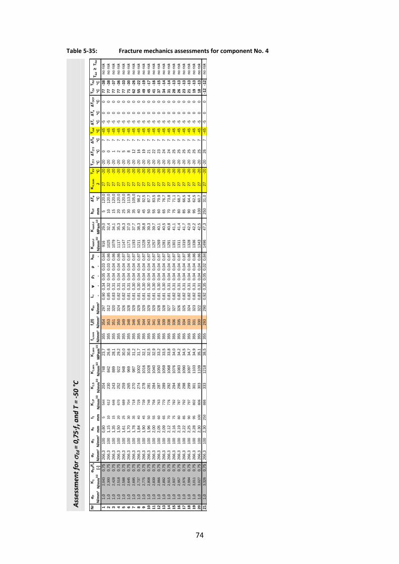
74
Table 5-35: Fracture mechanics assessments for component No. 4
Ass
essm
ent
for
Ed =
0,7
5∙f
y a
nd
T =
-50
°C
Nr
P
K1
Ed
/f y
P
Sa 0
t 1K
1,P
K1,
SK
1,ge
sK
1,ge
sf y,
nom
f y(t)
gy
L r
1
k R
6K
appl
,d
Kap
pl,d
b e
ff
T
KV,
nom
T KV
T 27J
T 2
7J
T R
T md
T r
T
T DC
FT E
dT R
d
N/m
m²
N/m
m3/
2[-]
N/m
m²
N/m
m²
mm
mm
N/m
m3/
2N
/mm
3/2
N/m
m3/
2M
Pam
1/2
N/m
m²
N/m
m²
N/m
m²
- -
- -
-N
/mm
3/2
MPa
m1/
2m
m°C
J°C
°C°C
°C°C
°C°C
°C°C
°C1
1,0
2,04
30,
7526
6,3
100
0,80
554
420
474
823
,735
535
429
70,
900,
340,
050,
030,
8491
629
,05
120,
027
-20
-20
07
-45
-50
077
-38
21,
02,
300
0,75
266,
310
01,
1510
612
230
842
26,6
355
353
312
0,85
0,32
0,04
0,03
0,86
1025
32,4
1012
0,0
27-2
0-2
00
7-4
5-5
00
77-3
83
1,0
2,42
80,
7526
6,3
100
1,35
1564
624
388
928
,135
535
132
00,
830,
310,
040,
040,
8610
7934
,115
120,
027
-20
-20
17
-45
-50
077
-37
41,
02,
518
0,75
266,
310
01,
5020
670
252
922
29,2
355
350
324
0,82
0,31
0,04
0,04
0,86
1117
35,3
2012
0,0
27-2
0-2
02
7-4
5-5
00
77-3
65
1,0
2,58
80,
7526
6,3
100
1,61
2568
925
994
830
,035
534
932
60,
820,
310,
040,
040,
8711
4736
,325
120,
027
-20
-20
57
-45
-50
077
-33
61,
02,
645
0,75
266,
310
01,
7030
704
265
969
30,6
355
348
328
0,81
0,31
0,04
0,04
0,87
1171
37,0
3011
3,9
27-2
0-2
08
7-4
5-5
00
71-3
07
1,0
2,69
50,
7526
6,3
100
1,78
3571
827
098
731
,235
534
632
90,
810,
300,
040,
040,
8711
9337
,735
105,
027
-20
-20
127
-45
-50
062
-26
81,
02,
737
0,75
266,
310
01,
8440
729
274
1002
31,7
355
345
329
0,81
0,30
0,04
0,04
0,87
1211
38,3
4098
,227
-20
-20
167
-45
-50
055
-22
91,
02,
775
0,75
266,
310
01,
9045
739
278
1016
32,1
355
344
329
0,81
0,30
0,04
0,04
0,87
1228
38,8
4592
,527
-20
-20
197
-45
-50
049
-19
101,
02,
808
0,75
266,
310
01,
9650
748
281
1028
32,5
355
343
329
0,81
0,30
0,04
0,04
0,87
1243
39,3
5087
,727
-20
-20
217
-45
-50
045
-17
111,
02,
839
0,75
266,
310
02,
0055
756
284
1040
32,9
355
341
329
0,81
0,30
0,04
0,04
0,87
1257
39,7
5583
,527
-20
-20
227
-45
-50
041
-16
121,
02,
866
0,75
266,
310
02,
0560
763
287
1050
33,2
355
340
328
0,81
0,30
0,04
0,04
0,87
1269
40,1
6079
,927
-20
-20
237
-45
-50
037
-15
131,
02,
892
0,75
266,
310
02,
0965
770
289
1059
33,5
355
339
328
0,81
0,30
0,04
0,04
0,87
1281
40,5
6576
,727
-20
-20
247
-45
-50
034
-14
141,
02,
915
0,75
266,
310
02,
1270
776
292
1068
33,8
355
338
327
0,81
0,31
0,04
0,04
0,87
1291
40,8
7073
,827
-20
-20
247
-45
-50
031
-14
151,
02,
937
0,75
266,
310
02,
1675
782
294
1076
34,0
355
336
327
0,82
0,31
0,04
0,04
0,87
1301
41,1
7571
,127
-20
-20
257
-45
-50
028
-13
161,
02,
957
0,75
266,
310
02,
1980
787
296
1083
34,2
355
335
326
0,82
0,31
0,04
0,04
0,87
1311
41,4
8068
,727
-20
-20
257
-45
-50
026
-13
171,
02,
976
0,75
266,
310
02,
2285
792
298
1090
34,5
355
334
325
0,82
0,31
0,04
0,04
0,87
1319
41,7
8566
,527
-20
-20
257
-45
-50
023
-13
181,
02,
994
0,75
266,
310
02,
2590
797
299
1097
34,7
355
333
324
0,82
0,31
0,04
0,04
0,86
1328
42,0
9064
,427
-20
-20
257
-45
-50
021
-13
191,
03,
011
0,75
266,
310
02,
2895
802
301
1103
34,9
355
331
323
0,82
0,31
0,04
0,04
0,86
1336
42,2
9562
,527
-20
-20
257
-45
-50
019
-13
201,
03,
027
0,75
266,
310
02,
3010
080
630
311
0935
,135
533
032
20,
830,
310,
040,
040,
8613
4342
,510
060
,727
-20
-20
257
-45
-50
018
-13
211,
03,
326
0,75
266,
310
02,
3025
088
633
312
1838
,535
529
329
00,
920,
350,
050,
020,
8414
9647
,325
031
,027
-20
-20
267
-45
-50
0-1
2-1
2
no ri
skno
risk
T Ed
≥ T
Rd
no ri
skno
risk
no ri
sk
no ri
skno
risk
no ri
skno
risk
no ri
skno
risk
no ri
sk
no ri
skno
risk
no ri
sk
no ri
skno
risk
no ri
skno
risk
no ri
skno
risk
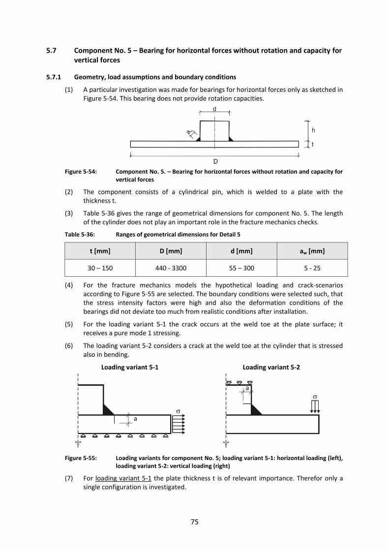
75
5.7 Component No. 5 – Bearing for horizontal forces without rotation and capacity for vertical forces
5.7.1 Geometry, load assumptions and boundary conditions
(1) A particular investigation was made for bearings for horizontal forces only as sketched in Figure 5-54. This bearing does not provide rotation capacities.
Figure 5-54: Component No. 5. – Bearing for horizontal forces without rotation and capacity for
vertical forces
(2) The component consists of a cylindrical pin, which is welded to a plate with the thickness t.
(3) Table 5-36 gives the range of geometrical dimensions for component No. 5. The length of the cylinder does not play an important role in the fracture mechanics checks.
Table 5-36: Ranges of geometrical dimensions for Detail 5
t [mm] D [mm] d [mm] aw [mm]
30 – 150 440 - 3300 55 – 300 5 - 25
(4) For the fracture mechanics models the hypothetical loading and crack-scenarios according to Figure 5-55 are selected. The boundary conditions were selected such, that the stress intensity factors were high and also the deformation conditions of the bearings did not deviate too much from realistic conditions after installation.
(5) For the loading variant 5-1 the crack occurs at the weld toe at the plate surface; it receives a pure mode 1 stressing.
(6) The loading variant 5-2 considers a crack at the weld toe at the cylinder that is stressed also in bending.
Loading variant 5-1 Loading variant 5-2
Figure 5-55: Loading variants for component No. 5; loading variant 5-1: horizontal loading (left), loading variant 5-2: vertical loading (right)
(7) For loading variant 5-1 the plate thickness t is of relevant importance. Therefor only a single configuration is investigated.
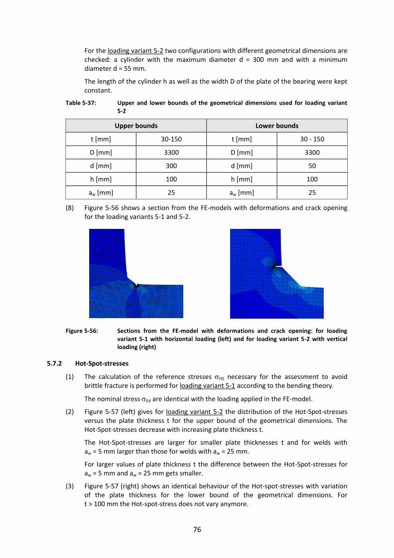
76
For the loading variant 5-2 two configurations with different geometrical dimensions are checked: a cylinder with the maximum diameter d = 300 mm and with a minimum diameter d = 55 mm.
The length of the cylinder h as well as the width D of the plate of the bearing were kept constant.
Table 5-37: Upper and lower bounds of the geometrical dimensions used for loading variant 5-2
Upper bounds Lower bounds
t [mm] 30-150 t [mm] 30 - 150
D [mm] 3300 D [mm] 3300
d [mm] 300 d [mm] 50
h [mm] 100 h [mm] 100
aw [mm] 25 aw [mm] 25
(8) Figure 5-56 shows a section from the FE-models with deformations and crack opening for the loading variants 5-1 and 5-2.
Figure 5-56: Sections from the FE-model with deformations and crack opening: for loading variant 5-1 with horizontal loading (left) and for loading variant 5-2 with vertical loading (right)
5.7.2 Hot-Spot-stresses
(1) The calculation of the reference stresses HS necessary for the assessment to avoid brittle fracture is performed for loading variant 5-1 according to the bending theory.
The nominal stress Ed are identical with the loading applied in the FE-model.
(2) Figure 5-57 (left) gives for loading variant 5-2 the distribution of the Hot-Spot-stresses versus the plate thickness t for the upper bound of the geometrical dimensions. The Hot-Spot-stresses decrease with increasing plate thickness t.
The Hot-Spot-stresses are larger for smaller plate thicknesses t and for welds with aw = 5 mm larger than those for welds with aw = 25 mm.
For larger values of plate thickness t the difference between the Hot-Spot-stresses for aw = 5 mm and aw = 25 mm gets smaller.
(3) Figure 5-57 (right) shows an identical behaviour of the Hot-spot-stresses with variation of the plate thickness for the lower bound of the geometrical dimensions. For t > 100 mm the Hot-spot-stress does not vary anymore.

77
Figure 5-57: Hot-Spot-stresses due to external unit loading for the loading variant 5-2: for upper bound of geometrical dimensions (left), for lower bound of geometrical dimensions (right)
5.7.3 Stress intensity factors
(1) Figure 5-58 (left) shows for the loading variant 5-1 the increase of the stress intensity factor K1 when the plate thickness t and hence the crack depth a0 is increased, all for the
unit loading N = 1 N/mm².
(2) The crack depths a0 are in the range of 1,701 mm to 2,505 mm.
The plate width D, the height h and the diameter d of the cylinder have no significant influence on K1.
(3) The Figure 5-58 (right) shows the minor influence of the throat thickness aw on K1. The calculations were performed with the maximum values aw.
Figure 5-58: K-values for the loading variant 5-1 for a unit loading N (t) = 1 N/mm (left) and K-values related to a constant horizontal load FH (right)
(4) For loading variant 5-2 Figure 5-59 (left) indicates the decrease of K with increasing plate thickness for the upper bound of the geometrical dimensions.
The mode 2 stresses lead to effective Keff-values which are a bit larger than the K1-values due to mode 1 stresses. For small weld sizes aw the K-values get larger.
(5) Figure 5-59 (right) gives the normalized -values, however with the relevant values for large throat thicknesses. The -values increase with increasing plate thicknesses t.
0
20
40
60
80
100
120
140
0 50 100 150 200 250
H
S[M
Pa]
t [mm]
configuration 5-2D = 3300 mm d = 300 mm h = 100 mm aw = 5 mm
aw = 25 mm
0
50
100
150
200
250
300
0 50 100 150 200 250
H
S[M
Pa]
t [mm]
configuration 5-2D = 3300 mm d = 50 mm h = 100 mm
aw = 5 mm
aw = 25 mm
5,0
5,5
6,0
6,5
7,0
20 40 60 80 100 120 140 160 180 200
stre
ss in
tens
ity fa
ctor
K1
t [mm]
configuration 5-1D = 3300 mm d = 300 mmh = 100 mm
initial crack size a0
N = const. = 1 N/mm
K1 = -7E-14t6 + 7E-11t5 - 3E-08t4 + 7E-06t3 - 0,001t2 + 0,0877t + 3,3597R2 = 1
aw = 5 mm
aw = 25 mm
aw = 15 mm
0,0
0,2
0,4
0,6
0,8
1,0
20 40 60 80 100 120 140 160
stre
ss in
tens
ity fa
ctor
K1
t [mm]
configuration 5-1D = 3300 mm d = 300 mmh = 100 mm initial crack size a0
FH = const.
aw = 25 mm
aw = 15 mm
aw = 5 mm

78
Figure 5-59: K-values for the loading variant 5-2 for variation of plate thickness t and upper bound of geometrical dimensions. K-values due to unit loading (left), normalized
-values related to HS = 1 N/mm² (right)
(6) For the lower bound of geometrical dimensions the function of K-values is similar as the one in Figure 5-60 (left). As derived for the upper bound of the geometrical dimensions the K-values get relevant for large weld sizes. The magnitude of K-values for the lower bound is significantly larger.
(7) In Figure 5-60 (right) the -values and also -values normalized for HS = 1 N/mm² are given; there is an increase of -values with larger t-values.
Figure 5-60: K-values for the loading variant 5-2 for variation of plate thickness t and lower bound of geometrical dimensions. K-values for unit loading (left), normalized
-values related to HS = 1 N/mm² (right)
5.7.4 Assessments to avoid brittle fracture
(1) The fracture-mechanics assessment are carried out for component No. 5 – Bearing for horizontal forces – for loading variant 5-1 in Table 5-40 and for loading variant 5-2 in Table 5-41.
(2) The results of the calculations are given in Table 5-38 and Table 5-39
Table 5-38: Limits of plate thickness for the component No. 5 for loading variant 5-1
Steel grade acc. to EN 10025
Ed 0°C -10°C -20°C -30°C -40°C -50°C
S355J2 0,25 ∙ fy 250*) 250*) 250*) 250*) 250*) 250*)
S355J2 0,50 ∙ fy 250*) 250*) 180 110 80 60
S355J2 0,75 ∙ fy 120 80 60 40 40 30
*) Assumption of a technical manufacturing limit (in theory element thicknesses with t ≥ 250 mm would be acceptable)
0
20
40
60
80
100
120
140
160
180
0 20 40 60 80 100 120 140 160
stre
ss in
tens
ity fa
ctor
K1,
Kef
f
t [mm]
configuration 5-2D = 3300 mmd = 300 mmh = 100 mm
a0 = const.
aw = 5 mm
aw = 15 mm
aw = 25 mm
K1
K1Keff
Keff
K1 Keff
1,0
1,2
1,4
1,6
1,8
2,0
0 20 40 60 80 100 120 140 160
stre
ss in
tens
ity fa
ctor
K
t [mm]
configuration 5-2D = 3300 mmd = 300 mmh = 100 mm
a0 = const.HS = const. = 1 N/mm
aw = 25 mm
aw = 5 mm
Keff
Keff
0
50
100
150
200
250
300
0 20 40 60 80 100 120 140 160
stre
ss in
tens
ity fa
ctor
K1,
Kef
f
t [mm]
configuration 5-2D = 3300 mmd = 50 mmh = 100 mm
a0 = const.
aw = 25 mm
K1
Keff
K = 0,0006∙t + 2,8849R2 = 0,9876
2,2
2,4
2,6
2,8
3,0
3,2
0 50 100 150 200
stre
ss in
tens
ity fa
ctor
K
t [mm]
configuration 5-2D = 3300 mmd = 50 mmh = 100 mm
a0 = const.
HS = const. = 1 N/mm
aw = 25 mmKeff
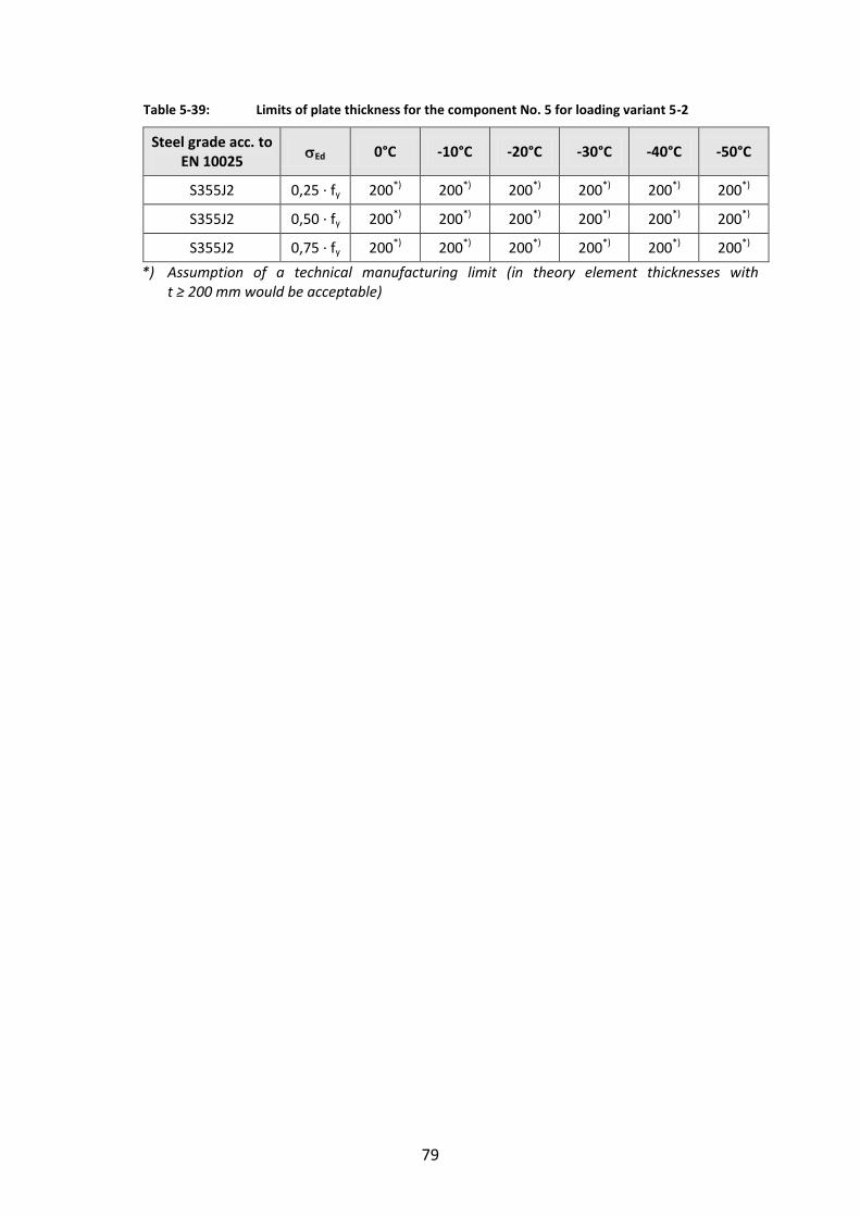
79
Table 5-39: Limits of plate thickness for the component No. 5 for loading variant 5-2
Steel grade acc. to EN 10025
Ed 0°C -10°C -20°C -30°C -40°C -50°C
S355J2 0,25 ∙ fy 200*) 200*) 200*) 200*) 200*) 200*)
S355J2 0,50 ∙ fy 200*) 200*) 200*) 200*) 200*) 200*)
S355J2 0,75 ∙ fy 200*) 200*) 200*) 200*) 200*) 200*)
*) Assumption of a technical manufacturing limit (in theory element thicknesses with t ≥ 200 mm would be acceptable)
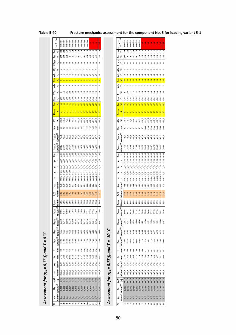
80
Table 5-40: Fracture mechanics assessment for the component No. 5 for loading variant 5-1
Ass
essm
ent
for
Ed =
0,7
5∙f
y a
nd
T =
0 °
C
Ass
essm
ent
for
Ed =
0,7
5∙f
y a
nd
T =
-10
°C
Nr
P
K1
Ed
/f y
P
Sa 0
t 1K
1,P
K1,
SK
1,ge
sK
1,ge
sf y,
nom
f y(t)
gy
L r
1
k R
6K
appl
,d
Kap
pl,d
b e
ff
T
KV,
nom
T KV
T 27J
T 2
7J
T R
T md
T r
T
T DC
FT E
dT R
d
N/m
m²
N/m
m3/
2[-]
N/m
m²
N/m
m²
mm
mm
N/m
m3/
2N
/mm
3/2
N/m
m3/
2M
Pam
1/2
N/m
m²
N/m
m²
N/m
m²
- -
- -
-N
/mm
3/2
MPa
m1/
2m
m°C
J°C
°C°C
°C°C
°C°C
°C°C
°C1
1,0
5,22
00,
7526
6,3
100
1,70
3013
9052
219
1260
,535
534
832
80,
810,
310,
040,
040,
8723
1273
,130
22,3
27-2
0-2
08
75
-50
029
-30
21,
05,
590
0,75
266,
310
01,
8440
1488
559
2047
64,7
355
345
329
0,81
0,30
0,04
0,04
0,87
2474
78,2
4012
,127
-20
-20
167
5-5
00
19-2
23
1,0
5,87
00,
7526
6,3
100
1,96
5015
6358
721
5068
,035
534
332
90,
810,
300,
040,
040,
8725
9882
,250
4,7
27-2
0-2
021
75
-50
012
-17
41,
06,
084
0,75
266,
310
02,
0560
1620
608
2228
70,5
355
340
328
0,81
0,30
0,04
0,04
0,87
2694
85,2
60-0
,827
-20
-20
237
5-5
00
6-1
55
1,0
6,25
00,
7526
6,3
100
2,12
7016
6462
522
8972
,435
533
832
70,
810,
310,
040,
040,
8727
6887
,570
-5,2
27-2
0-2
024
75
-50
02
-14
61,
06,
378
0,75
266,
310
02,
1980
1698
638
2336
73,9
355
335
326
0,82
0,31
0,04
0,04
0,87
2827
89,4
80-8
,727
-20
-20
257
5-5
00
-2-1
37
1,0
6,47
70,
7526
6,3
100
2,25
9017
2564
823
7275
,035
533
332
40,
820,
310,
040,
040,
8628
7290
,890
-11,
627
-20
-20
257
5-5
00
-5-1
38
1,0
6,55
40,
7526
6,3
100
2,30
100
1745
655
2400
75,9
355
330
322
0,83
0,31
0,04
0,04
0,86
2909
92,0
100
-14,
127
-20
-20
257
5-5
00
-7-1
39
1,0
6,61
30,
7526
6,3
100
2,35
110
1761
661
2422
76,6
355
328
321
0,83
0,31
0,04
0,04
0,86
2937
92,9
110
-16,
227
-20
-20
257
5-5
00
-9-1
310
1,0
6,65
90,
7526
6,3
100
2,39
120
1773
666
2439
77,1
355
325
319
0,84
0,31
0,04
0,04
0,86
2960
93,6
120
-18,
027
-20
-20
267
5-5
00
-11
-12
111,
06,
695
0,75
266,
310
02,
4313
017
8367
024
5277
,535
532
331
60,
840,
320,
040,
040,
8629
7894
,213
0-1
9,6
27-2
0-2
026
75
-50
0-1
3-1
212
1,0
6,72
20,
7526
6,3
100
2,47
140
1790
672
2462
77,9
355
320
314
0,85
0,32
0,04
0,04
0,86
2993
94,6
140
-21,
027
-20
-20
267
5-5
00
-14
-12
131,
06,
745
0,75
266,
310
02,
5115
017
9667
524
7078
,135
531
831
20,
850,
320,
040,
030,
8630
0695
,015
0-2
2,3
27-2
0-2
026
75
-50
0-1
5-1
220
1,0
6,79
00,
7526
6,3
100
2,60
180
1808
679
2487
78,6
355
310
306
0,87
0,33
0,04
0,03
0,85
3034
95,9
180
-25,
527
-20
-20
267
5-5
00
-19
-12
risk
no ri
skno
risk
T Ed
≥ T
Rd
no ri
skno
risk
no ri
sk
risk
risk
risk
no ri
sk
no ri
skno
risk
no ri
skno
risk
Nr
P
K1
Ed
/f y
P
Sa 0
t 1K
1,P
K1,
SK
1,ge
sK
1,ge
sf y,
nom
f y(t)
gy
L r
1
k R
6K
appl
,d
Kap
pl,d
b e
ff
T
KV,
nom
T KV
T 27J
T 2
7J
T R
T md
T r
T
T DC
FT E
dT R
d
N/m
m²
N/m
m3/
2[-]
N/m
m²
N/m
m²
mm
mm
N/m
m3/
2N
/mm
3/2
N/m
m3/
2M
Pam
1/2
N/m
m²
N/m
m²
N/m
m²
- -
- -
-N
/mm
3/2
MPa
m1/
2m
m°C
J°C
°C°C
°C°C
°C°C
°C°C
°C1
1,0
5,22
00,
7526
6,3
100
1,70
3013
9052
219
1260
,535
534
832
80,
810,
310,
040,
040,
8723
1273
,130
22,3
27-2
0-2
08
7-5
-50
019
-30
21,
05,
590
0,75
266,
310
01,
8440
1488
559
2047
64,7
355
345
329
0,81
0,30
0,04
0,04
0,87
2474
78,2
4012
,127
-20
-20
167
-5-5
00
9-2
23
1,0
5,87
00,
7526
6,3
100
1,96
5015
6358
721
5068
,035
534
332
90,
810,
300,
040,
040,
8725
9882
,250
4,7
27-2
0-2
021
7-5
-50
02
-17
41,
06,
084
0,75
266,
310
02,
0560
1620
608
2228
70,5
355
340
328
0,81
0,30
0,04
0,04
0,87
2694
85,2
60-0
,827
-20
-20
237
-5-5
00
-4-1
55
1,0
6,25
00,
7526
6,3
100
2,12
7016
6462
522
8972
,435
533
832
70,
810,
310,
040,
040,
8727
6887
,570
-5,2
27-2
0-2
024
7-5
-50
0-8
-14
61,
06,
378
0,75
266,
310
02,
1980
1698
638
2336
73,9
355
335
326
0,82
0,31
0,04
0,04
0,87
2827
89,4
80-8
,727
-20
-20
257
-5-5
00
-12
-13
71,
06,
477
0,75
266,
310
02,
2590
1725
648
2372
75,0
355
333
324
0,82
0,31
0,04
0,04
0,86
2872
90,8
90-1
1,6
27-2
0-2
025
7-5
-50
0-1
5-1
38
1,0
6,55
40,
7526
6,3
100
2,30
100
1745
655
2400
75,9
355
330
322
0,83
0,31
0,04
0,04
0,86
2909
92,0
100
-14,
127
-20
-20
257
-5-5
00
-17
-13
91,
06,
613
0,75
266,
310
02,
3511
017
6166
124
2276
,635
532
832
10,
830,
310,
040,
040,
8629
3792
,911
0-1
6,2
27-2
0-2
025
7-5
-50
0-1
9-1
310
1,0
6,65
90,
7526
6,3
100
2,39
120
1773
666
2439
77,1
355
325
319
0,84
0,31
0,04
0,04
0,86
2960
93,6
120
-18,
027
-20
-20
267
-5-5
00
-21
-12
111,
06,
695
0,75
266,
310
02,
4313
017
8367
024
5277
,535
532
331
60,
840,
320,
040,
040,
8629
7894
,213
0-1
9,6
27-2
0-2
026
7-5
-50
0-2
3-1
212
1,0
6,72
20,
7526
6,3
100
2,47
140
1790
672
2462
77,9
355
320
314
0,85
0,32
0,04
0,04
0,86
2993
94,6
140
-21,
027
-20
-20
267
-5-5
00
-24
-12
131,
06,
745
0,75
266,
310
02,
5115
017
9667
524
7078
,135
531
831
20,
850,
320,
040,
030,
8630
0695
,015
0-2
2,3
27-2
0-2
026
7-5
-50
0-2
5-1
220
1,0
6,79
00,
7526
6,3
100
2,60
180
1808
679
2487
78,6
355
310
306
0,87
0,33
0,04
0,03
0,85
3034
95,9
180
-25,
527
-20
-20
267
-5-5
00
-29
-12
no ri
sk
risk
risk
risk
risk
no ri
skris
kris
kris
k
risk
no ri
skno
risk
T Ed
≥ T
Rd
no ri
skno
risk
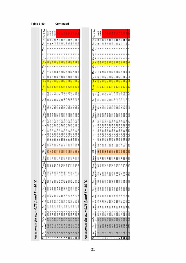
81
Table 5-40: Continued
Ass
essm
ent
for
Ed =
0,7
5∙f
y a
nd
T =
-20
°C
Ass
essm
ent
for
Ed =
0,7
5∙f
y a
nd
T =
-30
°C
Nr
P
K1
Ed
/f y
P
Sa 0
t 1K
1,P
K1,
SK
1,ge
sK
1,ge
sf y,
nom
f y(t)
gy
L r
1
k R
6K
appl
,d
Kap
pl,d
b e
ff
T
KV,
nom
T KV
T 27J
T 2
7J
T R
T md
T r
T
T DC
FT E
dT R
d
N/m
m²
N/m
m3/
2[-]
N/m
m²
N/m
m²
mm
mm
N/m
m3/
2N
/mm
3/2
N/m
m3/
2M
Pam
1/2
N/m
m²
N/m
m²
N/m
m²
- -
- -
-N
/mm
3/2
MPa
m1/
2m
m°C
J°C
°C°C
°C°C
°C°C
°C°C
°C1
1,0
5,22
00,
7526
6,3
100
1,70
3013
9052
219
1260
,535
534
832
80,
810,
310,
040,
040,
8723
1273
,130
22,3
27-2
0-2
08
7-1
5-5
00
9-3
02
1,0
5,59
00,
7526
6,3
100
1,84
4014
8855
920
4764
,735
534
532
90,
810,
300,
040,
040,
8724
7478
,240
12,1
27-2
0-2
016
7-1
5-5
00
-1-2
23
1,0
5,87
00,
7526
6,3
100
1,96
5015
6358
721
5068
,035
534
332
90,
810,
300,
040,
040,
8725
9882
,250
4,7
27-2
0-2
021
7-1
5-5
00
-8-1
74
1,0
6,08
40,
7526
6,3
100
2,05
6016
2060
822
2870
,535
534
032
80,
810,
300,
040,
040,
8726
9485
,260
-0,8
27-2
0-2
023
7-1
5-5
00
-14
-15
51,
06,
250
0,75
266,
310
02,
1270
1664
625
2289
72,4
355
338
327
0,81
0,31
0,04
0,04
0,87
2768
87,5
70-5
,227
-20
-20
247
-15
-50
0-1
8-1
46
1,0
6,37
80,
7526
6,3
100
2,19
8016
9863
823
3673
,935
533
532
60,
820,
310,
040,
040,
8728
2789
,480
-8,7
27-2
0-2
025
7-1
5-5
00
-22
-13
71,
06,
477
0,75
266,
310
02,
2590
1725
648
2372
75,0
355
333
324
0,82
0,31
0,04
0,04
0,86
2872
90,8
90-1
1,6
27-2
0-2
025
7-1
5-5
00
-25
-13
81,
06,
554
0,75
266,
310
02,
3010
017
4565
524
0075
,935
533
032
20,
830,
310,
040,
040,
8629
0992
,010
0-1
4,1
27-2
0-2
025
7-1
5-5
00
-27
-13
91,
06,
613
0,75
266,
310
02,
3511
017
6166
124
2276
,635
532
832
10,
830,
310,
040,
040,
8629
3792
,911
0-1
6,2
27-2
0-2
025
7-1
5-5
00
-29
-13
101,
06,
659
0,75
266,
310
02,
3912
017
7366
624
3977
,135
532
531
90,
840,
310,
040,
040,
8629
6093
,612
0-1
8,0
27-2
0-2
026
7-1
5-5
00
-31
-12
111,
06,
695
0,75
266,
310
02,
4313
017
8367
024
5277
,535
532
331
60,
840,
320,
040,
040,
8629
7894
,213
0-1
9,6
27-2
0-2
026
7-1
5-5
00
-33
-12
121,
06,
722
0,75
266,
310
02,
4714
017
9067
224
6277
,935
532
031
40,
850,
320,
040,
040,
8629
9394
,614
0-2
1,0
27-2
0-2
026
7-1
5-5
00
-34
-12
131,
06,
745
0,75
266,
310
02,
5115
017
9667
524
7078
,135
531
831
20,
850,
320,
040,
030,
8630
0695
,015
0-2
2,3
27-2
0-2
026
7-1
5-5
00
-35
-12
201,
06,
790
0,75
266,
310
02,
6018
018
0867
924
8778
,635
531
030
60,
870,
330,
040,
030,
8530
3495
,918
0-2
5,5
27-2
0-2
026
7-1
5-5
00
-39
-12
risk
no ri
skris
k
T Ed
≥ T
Rd
no ri
skno
risk
no ri
sk
risk
risk
risk
risk
risk
risk
risk
risk
Nr
P
K1
Ed
/f y
P
Sa 0
t 1K
1,P
K1,
SK
1,ge
sK
1,ge
sf y,
nom
f y(t)
gy
L r
1
k R
6K
appl
,d
Kap
pl,d
b e
ff
T
KV,
nom
T KV
T 27J
T 2
7J
T R
T md
T r
T
T DC
FT E
dT R
d
N/m
m²
N/m
m3/
2[-]
N/m
m²
N/m
m²
mm
mm
N/m
m3/
2N
/mm
3/2
N/m
m3/
2M
Pam
1/2
N/m
m²
N/m
m²
N/m
m²
- -
- -
-N
/mm
3/2
MPa
m1/
2m
m°C
J°C
°C°C
°C°C
°C°C
°C°C
°C1
1,0
5,22
00,
7526
6,3
100
1,70
3013
9052
219
1260
,535
534
832
80,
810,
310,
040,
040,
8723
1273
,130
22,3
27-2
0-2
08
7-2
5-5
00
-1-3
02
1,0
5,59
00,
7526
6,3
100
1,84
4014
8855
920
4764
,735
534
532
90,
810,
300,
040,
040,
8724
7478
,240
12,1
27-2
0-2
016
7-2
5-5
00
-11
-22
31,
05,
870
0,75
266,
310
01,
9650
1563
587
2150
68,0
355
343
329
0,81
0,30
0,04
0,04
0,87
2598
82,2
504,
727
-20
-20
217
-25
-50
0-1
8-1
74
1,0
6,08
40,
7526
6,3
100
2,05
6016
2060
822
2870
,535
534
032
80,
810,
300,
040,
040,
8726
9485
,260
-0,8
27-2
0-2
023
7-2
5-5
00
-24
-15
51,
06,
250
0,75
266,
310
02,
1270
1664
625
2289
72,4
355
338
327
0,81
0,31
0,04
0,04
0,87
2768
87,5
70-5
,227
-20
-20
247
-25
-50
0-2
8-1
46
1,0
6,37
80,
7526
6,3
100
2,19
8016
9863
823
3673
,935
533
532
60,
820,
310,
040,
040,
8728
2789
,480
-8,7
27-2
0-2
025
7-2
5-5
00
-32
-13
71,
06,
477
0,75
266,
310
02,
2590
1725
648
2372
75,0
355
333
324
0,82
0,31
0,04
0,04
0,86
2872
90,8
90-1
1,6
27-2
0-2
025
7-2
5-5
00
-35
-13
81,
06,
554
0,75
266,
310
02,
3010
017
4565
524
0075
,935
533
032
20,
830,
310,
040,
040,
8629
0992
,010
0-1
4,1
27-2
0-2
025
7-2
5-5
00
-37
-13
91,
06,
613
0,75
266,
310
02,
3511
017
6166
124
2276
,635
532
832
10,
830,
310,
040,
040,
8629
3792
,911
0-1
6,2
27-2
0-2
025
7-2
5-5
00
-39
-13
101,
06,
659
0,75
266,
310
02,
3912
017
7366
624
3977
,135
532
531
90,
840,
310,
040,
040,
8629
6093
,612
0-1
8,0
27-2
0-2
026
7-2
5-5
00
-41
-12
111,
06,
695
0,75
266,
310
02,
4313
017
8367
024
5277
,535
532
331
60,
840,
320,
040,
040,
8629
7894
,213
0-1
9,6
27-2
0-2
026
7-2
5-5
00
-43
-12
121,
06,
722
0,75
266,
310
02,
4714
017
9067
224
6277
,935
532
031
40,
850,
320,
040,
040,
8629
9394
,614
0-2
1,0
27-2
0-2
026
7-2
5-5
00
-44
-12
131,
06,
745
0,75
266,
310
02,
5115
017
9667
524
7078
,135
531
831
20,
850,
320,
040,
030,
8630
0695
,015
0-2
2,3
27-2
0-2
026
7-2
5-5
00
-45
-12
201,
06,
860
0,75
266,
310
02,
7625
018
2668
625
1279
,535
529
328
90,
920,
350,
050,
020,
8430
8697
,625
0-3
1,4
27-2
0-2
026
7-2
5-5
00
-54
-12
risk
risk
risk
risk
risk
risk
risk
risk
risk
risk
risk
risk
no ri
skno
risk
T Ed
≥ T
Rd
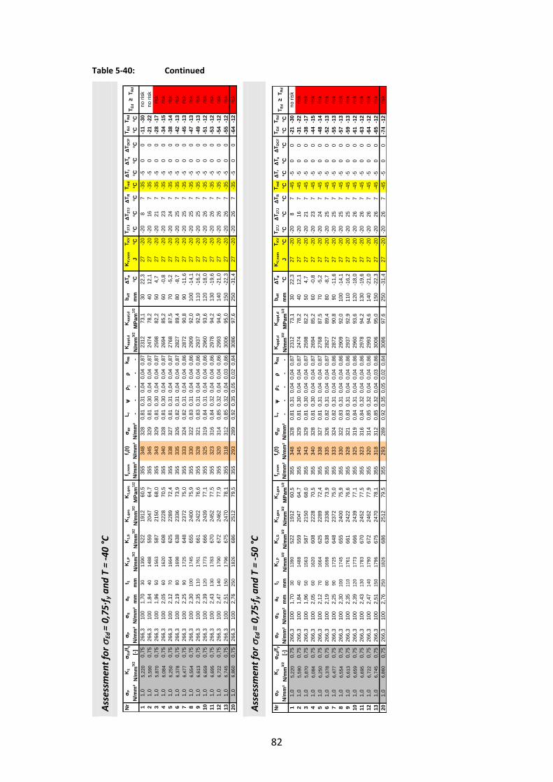
82
Table 5-40: Continued
Ass
essm
ent
for
Ed =
0,7
5∙f
y a
nd
T =
-40
°C
Ass
essm
ent
for
Ed =
0,7
5∙f
y a
nd
T =
-50
°C
Nr
P
K1
Ed
/f y
P
Sa 0
t 1K
1,P
K1,
SK
1,ge
sK
1,ge
sf y,
nom
f y(t)
gy
L r
1
k R
6K
appl
,d
Kap
pl,d
b e
ff
T
KV,
nom
T KV
T 27J
T 2
7J
T R
T md
T r
T
T DC
FT E
dT R
d
N/m
m²
N/m
m3/
2[-]
N/m
m²
N/m
m²
mm
mm
N/m
m3/
2N
/mm
3/2
N/m
m3/
2M
Pam
1/2
N/m
m²
N/m
m²
N/m
m²
- -
- -
-N
/mm
3/2
MPa
m1/
2m
m°C
J°C
°C°C
°C°C
°C°C
°C°C
°C1
1,0
5,22
00,
7526
6,3
100
1,70
3013
9052
219
1260
,535
534
832
80,
810,
310,
040,
040,
8723
1273
,130
22,3
27-2
0-2
08
7-3
5-5
00
-11
-30
21,
05,
590
0,75
266,
310
01,
8440
1488
559
2047
64,7
355
345
329
0,81
0,30
0,04
0,04
0,87
2474
78,2
4012
,127
-20
-20
167
-35
-50
0-2
1-2
23
1,0
5,87
00,
7526
6,3
100
1,96
5015
6358
721
5068
,035
534
332
90,
810,
300,
040,
040,
8725
9882
,250
4,7
27-2
0-2
021
7-3
5-5
00
-28
-17
41,
06,
084
0,75
266,
310
02,
0560
1620
608
2228
70,5
355
340
328
0,81
0,30
0,04
0,04
0,87
2694
85,2
60-0
,827
-20
-20
237
-35
-50
0-3
4-1
55
1,0
6,25
00,
7526
6,3
100
2,12
7016
6462
522
8972
,435
533
832
70,
810,
310,
040,
040,
8727
6887
,570
-5,2
27-2
0-2
024
7-3
5-5
00
-38
-14
61,
06,
378
0,75
266,
310
02,
1980
1698
638
2336
73,9
355
335
326
0,82
0,31
0,04
0,04
0,87
2827
89,4
80-8
,727
-20
-20
257
-35
-50
0-4
2-1
37
1,0
6,47
70,
7526
6,3
100
2,25
9017
2564
823
7275
,035
533
332
40,
820,
310,
040,
040,
8628
7290
,890
-11,
627
-20
-20
257
-35
-50
0-4
5-1
38
1,0
6,55
40,
7526
6,3
100
2,30
100
1745
655
2400
75,9
355
330
322
0,83
0,31
0,04
0,04
0,86
2909
92,0
100
-14,
127
-20
-20
257
-35
-50
0-4
7-1
39
1,0
6,61
30,
7526
6,3
100
2,35
110
1761
661
2422
76,6
355
328
321
0,83
0,31
0,04
0,04
0,86
2937
92,9
110
-16,
227
-20
-20
257
-35
-50
0-4
9-1
310
1,0
6,65
90,
7526
6,3
100
2,39
120
1773
666
2439
77,1
355
325
319
0,84
0,31
0,04
0,04
0,86
2960
93,6
120
-18,
027
-20
-20
267
-35
-50
0-5
1-1
211
1,0
6,69
50,
7526
6,3
100
2,43
130
1783
670
2452
77,5
355
323
316
0,84
0,32
0,04
0,04
0,86
2978
94,2
130
-19,
627
-20
-20
267
-35
-50
0-5
3-1
212
1,0
6,72
20,
7526
6,3
100
2,47
140
1790
672
2462
77,9
355
320
314
0,85
0,32
0,04
0,04
0,86
2993
94,6
140
-21,
027
-20
-20
267
-35
-50
0-5
4-1
213
1,0
6,74
50,
7526
6,3
100
2,51
150
1796
675
2470
78,1
355
318
312
0,85
0,32
0,04
0,03
0,86
3006
95,0
150
-22,
327
-20
-20
267
-35
-50
0-5
5-1
220
1,0
6,86
00,
7526
6,3
100
2,76
250
1826
686
2512
79,5
355
293
289
0,92
0,35
0,05
0,02
0,84
3086
97,6
250
-31,
427
-20
-20
267
-35
-50
0-6
4-1
2
risk
risk
risk
risk
T Ed
≥ T
Rd
no ri
skno
risk
risk
risk
risk
risk
risk
risk
risk
risk
Nr
P
K1
Ed
/f y
P
Sa 0
t 1K
1,P
K1,
SK
1,ge
sK
1,ge
sf y,
nom
f y(t)
gy
L r
1
k R
6K
appl
,d
Kap
pl,d
b e
ff
T
KV,
nom
T KV
T 27J
T 2
7J
T R
T md
T r
T
T DC
FT E
dT R
d
N/m
m²
N/m
m3/
2[-]
N/m
m²
N/m
m²
mm
mm
N/m
m3/
2N
/mm
3/2
N/m
m3/
2M
Pam
1/2
N/m
m²
N/m
m²
N/m
m²
- -
- -
-N
/mm
3/2
MPa
m1/
2m
m°C
J°C
°C°C
°C°C
°C°C
°C°C
°C1
1,0
5,22
00,
7526
6,3
100
1,70
3013
9052
219
1260
,535
534
832
80,
810,
310,
040,
040,
8723
1273
,130
22,3
27-2
0-2
08
7-4
5-5
00
-21
-30
21,
05,
590
0,75
266,
310
01,
8440
1488
559
2047
64,7
355
345
329
0,81
0,30
0,04
0,04
0,87
2474
78,2
4012
,127
-20
-20
167
-45
-50
0-3
1-2
23
1,0
5,87
00,
7526
6,3
100
1,96
5015
6358
721
5068
,035
534
332
90,
810,
300,
040,
040,
8725
9882
,250
4,7
27-2
0-2
021
7-4
5-5
00
-38
-17
41,
06,
084
0,75
266,
310
02,
0560
1620
608
2228
70,5
355
340
328
0,81
0,30
0,04
0,04
0,87
2694
85,2
60-0
,827
-20
-20
237
-45
-50
0-4
4-1
55
1,0
6,25
00,
7526
6,3
100
2,12
7016
6462
522
8972
,435
533
832
70,
810,
310,
040,
040,
8727
6887
,570
-5,2
27-2
0-2
024
7-4
5-5
00
-48
-14
61,
06,
378
0,75
266,
310
02,
1980
1698
638
2336
73,9
355
335
326
0,82
0,31
0,04
0,04
0,87
2827
89,4
80-8
,727
-20
-20
257
-45
-50
0-5
2-1
37
1,0
6,47
70,
7526
6,3
100
2,25
9017
2564
823
7275
,035
533
332
40,
820,
310,
040,
040,
8628
7290
,890
-11,
627
-20
-20
257
-45
-50
0-5
5-1
38
1,0
6,55
40,
7526
6,3
100
2,30
100
1745
655
2400
75,9
355
330
322
0,83
0,31
0,04
0,04
0,86
2909
92,0
100
-14,
127
-20
-20
257
-45
-50
0-5
7-1
39
1,0
6,61
30,
7526
6,3
100
2,35
110
1761
661
2422
76,6
355
328
321
0,83
0,31
0,04
0,04
0,86
2937
92,9
110
-16,
227
-20
-20
257
-45
-50
0-5
9-1
310
1,0
6,65
90,
7526
6,3
100
2,39
120
1773
666
2439
77,1
355
325
319
0,84
0,31
0,04
0,04
0,86
2960
93,6
120
-18,
027
-20
-20
267
-45
-50
0-6
1-1
211
1,0
6,69
50,
7526
6,3
100
2,43
130
1783
670
2452
77,5
355
323
316
0,84
0,32
0,04
0,04
0,86
2978
94,2
130
-19,
627
-20
-20
267
-45
-50
0-6
3-1
212
1,0
6,72
20,
7526
6,3
100
2,47
140
1790
672
2462
77,9
355
320
314
0,85
0,32
0,04
0,04
0,86
2993
94,6
140
-21,
027
-20
-20
267
-45
-50
0-6
4-1
213
1,0
6,74
50,
7526
6,3
100
2,51
150
1796
675
2470
78,1
355
318
312
0,85
0,32
0,04
0,03
0,86
3006
95,0
150
-22,
327
-20
-20
267
-45
-50
0-6
5-1
220
1,0
6,86
00,
7526
6,3
100
2,76
250
1826
686
2512
79,5
355
293
289
0,92
0,35
0,05
0,02
0,84
3086
97,6
250
-31,
427
-20
-20
267
-45
-50
0-7
4-1
2
risk
risk
risk
risk
risk
risk
risk
risk
risk
risk
T Ed
≥ T
Rd
risk
risk
risk
no ri
sk

83
Table 5-41: Fracture mechanics assessment for the component No. 5 for loading variant 5-2
Ass
essm
ent
for
Ed =
0,7
5∙f
y a
nd
T =
-50
°C
Nr
P
K1
Ed
/f y
P
Sa 0
t 1K
1,P
K1,
SK
1,ge
sK
1,ge
sf y,
nom
f y(t)
gy
L r
1
k R
6K
appl
,d
Kap
pl,d
b e
ff
T
KV,
nom
T KV
T 27J
T 2
7J
T R
T md
T r
T
T DC
FT E
dT R
d
N/m
m²
N/m
m3/
2[-]
N/m
m²
N/m
m²
mm
mm
N/m
m3/
2N
/mm
3/2
N/m
m3/
2M
Pam
1/2
N/m
m²
N/m
m²
N/m
m²
- -
- -
-N
/mm
3/2
MPa
m1/
2m
m°C
J°C
°C°C
°C°C
°C°C
°C°C
°C1
1,0
2,45
00,
7526
6,3
100
2,85
2565
224
589
728
,435
534
934
40,
770,
290,
040,
040,
8810
7333
,925
120,
027
-20
-20
57
-45
-50
077
-33
21,
02,
485
0,75
266,
310
02,
8535
662
248
910
28,8
355
346
342
0,78
0,29
0,04
0,04
0,88
1090
34,5
3512
0,0
27-2
0-2
012
7-4
5-5
00
77-2
63
1,0
2,59
40,
7526
6,3
100
2,85
4569
125
995
030
,035
534
433
90,
790,
290,
040,
040,
8711
4036
,145
109,
027
-20
-20
197
-45
-50
066
-19
41,
02,
778
0,75
266,
310
02,
8555
740
278
1017
32,2
355
341
337
0,79
0,30
0,04
0,04
0,87
1224
38,7
5588
,527
-20
-20
227
-45
-50
045
-16
51,
02,
878
0,75
266,
310
02,
8565
766
288
1054
33,3
355
339
334
0,80
0,30
0,04
0,04
0,87
1270
40,2
6578
,027
-20
-20
247
-45
-50
035
-14
61,
02,
904
0,75
266,
310
02,
8575
773
290
1064
33,6
355
336
332
0,80
0,30
0,04
0,04
0,87
1284
40,6
7573
,227
-20
-20
257
-45
-50
030
-13
71,
02,
922
0,75
266,
310
02,
8585
778
292
1070
33,8
355
334
329
0,81
0,30
0,04
0,04
0,87
1293
40,9
8569
,527
-20
-20
257
-45
-50
027
-13
81,
02,
952
0,75
266,
310
02,
8595
786
295
1081
34,2
355
331
327
0,81
0,31
0,04
0,04
0,87
1308
41,3
9565
,627
-20
-20
257
-45
-50
023
-13
91,
02,
948
0,75
266,
310
02,
8510
578
529
510
8034
,135
532
932
40,
820,
310,
040,
040,
8613
0741
,310
563
,727
-20
-20
257
-45
-50
021
-13
101,
02,
957
0,75
266,
310
02,
8511
578
729
610
8334
,235
532
632
20,
830,
310,
040,
040,
8613
1241
,511
561
,427
-20
-20
267
-45
-50
018
-12
111,
02,
964
0,75
266,
310
02,
8512
578
929
610
8534
,335
532
431
90,
830,
310,
040,
040,
8613
1741
,612
559
,327
-20
-20
267
-45
-50
016
-12
121,
02,
970
0,75
266,
310
02,
8513
579
129
710
8834
,435
532
131
70,
840,
320,
040,
040,
8613
2141
,813
557
,527
-20
-20
267
-45
-50
014
-12
131,
02,
975
0,75
266,
310
02,
8514
579
229
810
9034
,535
531
931
40,
850,
320,
040,
040,
8613
2441
,914
555
,727
-20
-20
267
-45
-50
013
-12
141,
02,
979
0,75
266,
310
02,
8515
579
329
810
9134
,535
531
631
20,
850,
320,
040,
030,
8613
2842
,015
554
,227
-20
-20
267
-45
-50
011
-12
151,
02,
984
0,75
266,
310
02,
8516
579
429
810
9334
,635
531
431
00,
860,
320,
040,
030,
8513
3142
,116
552
,727
-20
-20
267
-45
-50
010
-12
161,
02,
990
0,75
266,
310
02,
8517
579
629
910
9534
,635
531
130
70,
870,
330,
040,
030,
8513
3542
,217
551
,227
-20
-20
267
-45
-50
08
-12
171,
02,
996
0,75
266,
310
02,
8518
579
830
010
9734
,735
530
930
50,
870,
330,
040,
030,
8513
3942
,318
549
,827
-20
-20
267
-45
-50
07
-12
181,
03,
002
0,75
266,
310
02,
8519
579
930
010
9934
,835
530
630
20,
880,
330,
040,
030,
8513
4342
,519
548
,527
-20
-20
267
-45
-50
05
-12
191,
03,
008
0,75
266,
310
02,
8520
580
130
111
0234
,835
530
430
00,
890,
330,
040,
030,
8513
4742
,620
547
,227
-20
-20
267
-45
-50
04
-12
no ri
skno
risk
no ri
skno
risk
no ri
skno
risk
no ri
skno
risk
no ri
skno
risk
no ri
skno
risk
no ri
skno
risk
no ri
skno
risk
no ri
skno
risk
T Ed
≥ T
Rd
no ri
sk
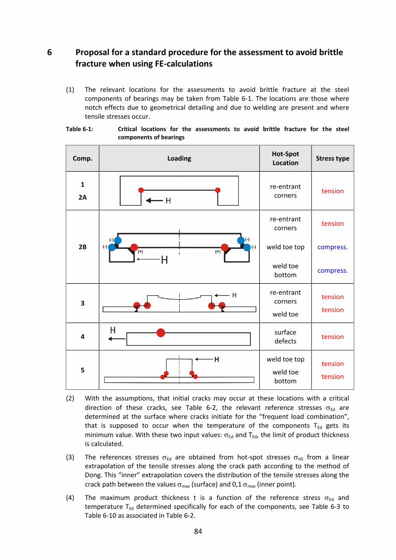
84
6 Proposal for a standard procedure for the assessment to avoid brittle fracture when using FE-calculations
(1) The relevant locations for the assessments to avoid brittle fracture at the steel components of bearings may be taken from Table 6-1. The locations are those where notch effects due to geometrical detailing and due to welding are present and where tensile stresses occur.
Table 6-1: Critical locations for the assessments to avoid brittle fracture for the steel components of bearings
Comp. Loading Hot-Spot Location
Stress type
1
2A
re-entrant corners
tension
2B
re-entrant corners
tension
weld toe top compress.
weld toe bottom
compress.
3
re-entrant corners
weld toe
tension
tension
4
surface defects
tension
5
weld toe top
weld toe bottom
tension
tension
(2) With the assumptions, that initial cracks may occur at these locations with a critical
direction of these cracks, see Table 6-2, the relevant reference stresses Ed are determined at the surface where cracks initiate for the “frequent load combination”, that is supposed to occur when the temperature of the components TEd gets its
minimum value. With these two input values: Ed and TEd, the limit of product thickness is calculated.
(3) The references stresses Ed are obtained from hot-spot stresses HS from a linear extrapolation of the tensile stresses along the crack path according to the method of Dong. This “inner” extrapolation covers the distribution of the tensile stresses along the
crack path between the values max (surface) and 0,1 max (inner point).
(4) The maximum product thickness t is a function of the reference stress Ed and temperature TEd determined specifically for each of the components, see Table 6-3 to Table 6-10 as associated in Table 6-2.

85
(5) These tables give the results for the most onerous loading variant used in section 5.
Table 6-2: Locations and directions of cracks as used to determined Ed = HS
Component Sketch Results
1
Top component – rotationally-symmetric
Table 6-3
2A
Top component – axisymmetric
Table 6-4
2B
Top component – axisymmetric, welded
Table 6-5 (element
thickness t1)
Table 6-6 (element
thickness t2)
3
Bottom component
Table 6-7 (element
thickness t1)
Table 6-8 (element
thickness t2)
4
Anchor plate
Table 6-9
5
Bearing for horizontal forces
Table 6-10

86
Table 6-3: Limits of plate thickness for component No. 1 – Rotationally-symmetric top component of bearing
Steel grade acc. to EN 10025
Ed 0°C -10°C -20°C -30°C -40°C -50°C
[mm]
S355J2 0,25 ∙ fy 250*) 250*) 250*) 250*) 250*) 250*)
S355J2 0,50 ∙ fy 250*) 250*) 250*) 250*) 250*) 250*)
S355J2 0,75 ∙ fy 250*) 250*) 250*) 250*) 250*) 235
*) Assumption of a technical manufacturing limit (in theory element thicknesses with t ≥ 250 mm would be acceptable)
Table 6-4: Limits of plate thickness for component No. 2A – Axisymmetric top component
Steel grade acc. to EN 10025
Ed 0°C -10°C -20°C -30°C -40°C -50°C
[mm]
S355J2 0,25 ∙ fy 250*) 250*) 250*) 250*) 250*) 250*)
S355J2 0,50 ∙ fy 250*) 250*) 250*) 250*) 250*) 250*)
S355J2 0,75 ∙ fy 250*) 250*) 250*) 250*) 250*) 240
*) Assumption of a technical manufacturing limit (in theory element thicknesses with t ≥ 250 mm would be acceptable)
Table 6-5: Limits of plate thickness t1 for component No. 2B - Welded top component of bearing
Steel grade acc. to EN 10025
Ed 0°C -10°C -20°C -30°C -40°C -50°C
[mm]
S355J2 0,25 ∙ fy 300*) 300*) 300*) 300*) 300*) 300*)
S355J2 0,50 ∙ fy 300*) 300*) 300*) 300*) 300*) 300*)
S355J2 0,75 ∙ fy 300*) 300*) 300*) 300*) 300*) 300*)
*) Assumption of a technical manufacturing limit (in theory element thicknesses with t ≥ 300 mm would be acceptable)
Table 6-6: Limits of plate thickness t2 for component No. 2B - Welded top component of bearing
Steel grade acc. to EN 10025
Ed 0°C -10°C -20°C -30°C -40°C -50°C
[mm]
S355J2 0,25 ∙ fy 200*) 200 190 170 150 130
*) Assumption of a technical manufacturing limit (in theory element thicknesses with t ≥ 200 mm would be acceptable)

87
Table 6-7: Limits of plate thickness t1 for component No. 3 - Bottom component of bearing
Steel grade acc. to EN 10025
Ed 0°C -10°C -20°C -30°C -40°C -50°C
[mm]
S355J2 0,25 ∙ fy 250*) 250*) 250*) 250*) 250*) 250*)
S355J2 0,50 ∙ fy 250*) 250*) 250*) 250*) 250*) 250*)
S355J2 0,75 ∙ fy 250*) 250*) 250*) 200 140 110
*) Assumption of a technical manufacturing limit (in theory element thicknesses with t ≥ 250 mm would be acceptable)
Table 6-8: Limits of plate thickness t2 for component No. 3 - Bottom component of bearing
Steel grade acc. to EN 10025
Ed 0°C -10°C -20°C -30°C -40°C -50°C
[mm]
S355J2 0,25 ∙ fy 250*) 250*) 250*) 250*) 250*) 250*)
S355J2 0,50 ∙ fy 250*) 250*) 250*) 250*) 250*) 250*)
S355J2 0,75 ∙ fy 250*) 250*) 250*) 200 140 110
*) Assumption of a technical manufacturing limit (in theory element thicknesses with t ≥ 250 mm would be acceptable)
Table 6-9: Limits of plate thickness for component No. 4 - Anchor plate
Steel grade acc. to EN 10025
Ed 0°C -10°C -20°C -30°C -40°C -50°C
[mm]
S355J2 0,25 ∙ fy 250*) 250*) 250*) 250*) 250*) 250*)
S355J2 0,50 ∙ fy 250*) 250*) 250*) 250*) 250*) 250*)
S355J2 0,75 ∙ fy 250*) 250*) 250*) 250*) 250*) 250*)
*) Assumption of a technical manufacturing limit (in theory element thicknesses with t ≥ 250 mm would be acceptable)
Table 6-10: Limits of plate thickness for component No. 5 – Bearing for horizontal loads
Steel grade acc. to EN 10025
Ed 0°C -10°C -20°C -30°C -40°C -50°C
[mm]
S355J2 0,25 ∙ fy 250*) 250*) 250*) 250*) 250*) 250*)
S355J2 0,50 ∙ fy 250*) 250*) 180 110 80 60
S355J2 0,75 ∙ fy 120 80 60 40 40 30
*) Assumption of a technical manufacturing limit (in theory element thicknesses with t ≥ 250 mm would be acceptable)
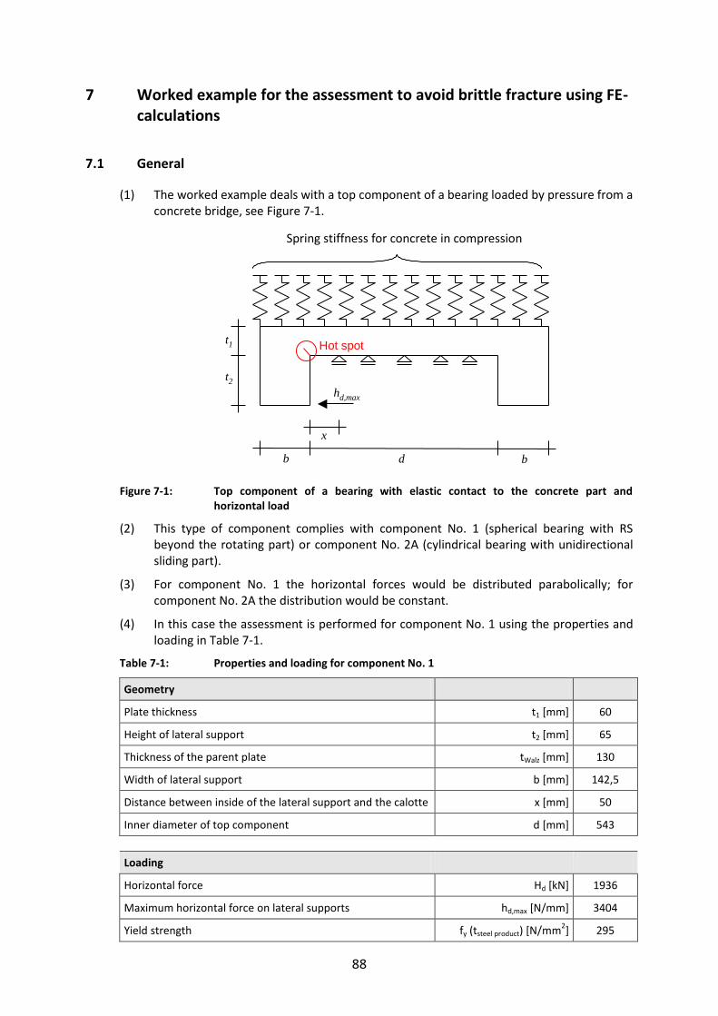
88
7 Worked example for the assessment to avoid brittle fracture using FE-calculations
7.1 General
(1) The worked example deals with a top component of a bearing loaded by pressure from a concrete bridge, see Figure 7-1.
Figure 7-1: Top component of a bearing with elastic contact to the concrete part and horizontal load
(2) This type of component complies with component No. 1 (spherical bearing with RS beyond the rotating part) or component No. 2A (cylindrical bearing with unidirectional sliding part).
(3) For component No. 1 the horizontal forces would be distributed parabolically; for component No. 2A the distribution would be constant.
(4) In this case the assessment is performed for component No. 1 using the properties and loading in Table 7-1.
Table 7-1: Properties and loading for component No. 1
Geometry
Plate thickness t1 [mm] 60
Height of lateral support t2 [mm] 65
Thickness of the parent plate tWalz [mm] 130
Width of lateral support b [mm] 142,5
Distance between inside of the lateral support and the calotte x [mm] 50
Inner diameter of top component d [mm] 543
Loading
Horizontal force Hd [kN] 1936
Maximum horizontal force on lateral supports hd,max [N/mm] 3404
Yield strength fy (tsteel product) [N/mm2] 295
Druckfedern für Betonpressung
hd,max
Hot spot
t2
t1
b bd
x
Spring stiffness for concrete in compression

89
(5) In order to take into account non-linear effects of the elastic contact between concrete and steel the calculation has been carried out using FEM.
(6) For concrete C30/40 was chosen.
(7) The concrete pressure is determined by bi-linear spring-elements, see Figure 7-2, where the limit pressure of 3∙fcd has been used.
Figure 7-2: Spring-characteristic for the concrete surface
(8) The numerical analysis was carried with the programme ANSYS12. The use of 2-dimensional sections makes the use of 2-dimensional Finite Elements possible:
- Plane 82 for linear elastic material properties for steel, i.e. modulus of elasticity
210.000 N/mm² and Poisson ratio = 0.3,
- COMBIN 39 as bilinear spring model for the concrete pressure.
7.2 Determination of the Hot-Spot-stresses
(1) The mechanical model in Figure 7-1 can be simplified for the safety assessment at the potential crack location to the model given in Figure 7-3.
Figure 7-3: Mechanical model for the potential crack detail
(2) The calculations are performed with a Finite-Element-model according to Figure 7-4, where the interface to the concrete is reproduced by bilinear springs.
s [mm]
[N/mm2]
3 fcd
Ecm
Druckfedern
Horizontalkraft
Hot spot mit r = 1mmt2
t1
b Abstand bis zur Kalotte, z.B. 50mm
Potentieller Rissquerschnitt
45°
Potential direction of crack
Hot spot with r = 1 mm
Horizontal force
Springs modeling the elasticity of concrete in compression
Distance to edge edge of calotte, e.g. 50 mm

90
Figure 7-4: Location and orientation of crack in the FE-mesh
(3) The radius at the critical detail is 1 mm.
(4) The horizontal force applied is 3404 N/mm.
(5) The mesh-length in the area of crack is 1x1 mm and has been confirmed by convergence-studies.
(6) For the evaluation of the principal stresses, which are nearly orientated perpendicularly to the potential crack direction, the standard hot-spot-stress method with non-linear surface extrapolation along the horizontal and the vertical path in Figure 7-4 is used.
(7) The principal stress HS for the horizontal extrapolation gives 106,3 N/mm² and for the vertical extrapolation 127,4 N/mm². For the vertical extrapolation the effect on the principal stress at the lateral supports at the point of the horizontal load application was separated.
extrapolation in horizontal direction extrapolation in vertical direction
0
200
400
600
800
1000
0 10 20 30 40 50
H
S[N
/mm
2 ]
x [mm]
1
H
0
200
400
600
800
1000
0 10 20 30 40 50 60
H
S[N
/mm
2 ]
y [mm]
1
H
Figure 7-5: Determination of the principal hot-spot stress HS by means of non-linear surface
extrapolation
7.3 Assessment
(1) The assessment is based on
Ed = 178 N/mm²
vertical path y
horizontal path x
bilinear springs
1
HS
1
HS

91
resulting from the static analysis of the bearing and hence
64,0295
178
fy
Ed
(2) According to Table 6-3 the dimensions of the steel-component are in the safe-area.

92
8 Simplified assessment with reference to ultimate limit state verifications
8.1 General
(1) The design of bearings for Ultimate Limit States yields in general the dimensions as given in Table 3-2.
(2) In the following it is assumed that
1. the ultimate limit state assessments are carried out using the elastic bending theory
for bars with the stress bend,d limited by the yield strength,
2. the loading assumptions are compatible with deformations,
3. assessments are carried out for the critical sections perpendicular to the neutral axis (and not in the direction of the probable crack path),
4. assessments are performed with the design values of action effects (from factored loads),
5. notch effects are neglected in using the elastic bending theory for bars.
(3) In order to establish a link between the reference stresses Ed defined as Hot-Spot-stresses according to Dong, for which the fracture mechanics assessments yielded the
thickness limits in Table 6-3 to Table 6-10, and the stresses bend,d from the ultimate limit state assessments the following correlations are necessary:
1. Difference between the load-level for “frequent” loads and the load level for ultimate limit state checks,
2. Differences between the Hot-Spot-stress HS from the linearization along the crack
path and the bending stress bend,d limited by the yield strength fy in the adjacent critical section perpendicular to the neutral axis.
8.2 Correlations
(1) To estimate the difference between the load-level for “frequent loads” and for ultimate limit state assessment, the case of canal bridges is adopted, for which
- the “frequent” load is defined by the permanent load (G+W) and
- the design load for ultimate limit states is G(G+W) where G = 1,35.
Hence the “frequent” load is equal to 1/1.35 = 0,75 of the ultimate load.
(2) As the bending stress bend,d for the critical cross-section perpendicular to the neutral
axis according to Figure 4-6a is in general smaller than the Hot-Spot-stress Ed along the
crack path, it is assumed, that the reference stress Ed equal to the Hot-Spot-stress along
the crack path can be correlated with the bending stress bend,d according to the bending theory in the following way:
(3) Using the assumptions (1) and (2) the reference stress Ed for the fracture mechanics assessment can be defined by
Ed = 0.75∙kDong∙bend,d (8-1)

93
where
Ed is determined according to the linear bending theory in the critical section perpendicular to the neutral axis for “frequent” loads
bend,d is the ultimate stress determined in a simplified way according to the elastic bending theory in the critical cross section perpendicular to the neutral axis for action effects
from loads factored with .
fy is the yield strength which limits the ultimate limit state assessment in the critical section perpendicular to the neutral axis
0,75 is the correlation factor between “frequent” load and the design load for ultimate limit states.
kDong is the correlation coefficient between the Hot-Spot-stress
HS according to Dong, see Figure 4-11 and the stress bend determined according to the elastic bending theory for the critical cross section perpendicular to the neutral axis
however with the same load level as for HS.
Figure 8-1 gives an example.
Figure 8-1: Correlation coefficient between the Hot-Spot-stress HS according to Dong and
stress bend according to the bending theory for the critical cross section perpendicular to the neutral axis
8.3 Consequences for the choice of material to avoid brittle fracture
(1) The consequences from the simplifications in 8.1 and 8.2 are demonstrated in Table 8-1. The results are safe-sided.
1,0
1,2
1,4
1,6
1,8
2,0
0 50 100 150 200 250
k Don
g[-]
t1 [mm]
kDong ≈ 1,80
t1
t2
bd/2
D/2
horizontal load H
Bieg
critical cross sectionperpendicular to the neutral axis

94
Table 8-1: Choice of material for steel components of bearings for the upper and bounds of dimensions for bearing type A and type B and steel S355J2 for TEd = - 30°C
No. Component Geometry
Type A Geometry
Type B Limits
1
Top component
(Sliding plate and lateral guiderail)
t: 55 – 315 mm
t1: 20 – 215 mm
t2: 25 – 100 mm D: 500 – 1800 mm
d: 355 - 1385 mm
b: 50 - 505 mm
t = 250 mm
2A
Top component
(sliding plate and lateral guiderail)
t: 55 – 315 mm
t1: 20 – 215 mm
t2: 25 – 100 mm D: 500 – 1800 mm
d: 355 - 1385 mm
b: 50 - 500 mm
t = 250 mm
2B
Top component
(sliding plate and lateral guiderail)
t1: 55 – 285 mm
t2: 55 – 170 mm
aw: 12 - 42 mm
(K oder Y-Naht)
D: 440 – 2580 mm
b: 55 - 570 mm
t1 = 300 mm
t2 = 170 mm
3
Bottom component
t: 55 – 255 mm
t1: 20 – 55 mm
t2: 20 – 60 mm
t3: 35 – 150 mm D: 330 – 1800 mm
b: 40-100 mm
r: 135-590 mm
t: 55 – 255 mm
t1: 20 – 55 mm
t2: 20 – 60 mm
t3: 35 – 150 mm D: 330 – 1800 mm
b: 40-100 mm
r: 135-590 mm
t1 = 200 mm
t2 = 200 mm
4
Anchor plate
t: ≥ 55 mm D: 440-3300 mm
t: ≥ 55 mm D: 440-3300 mm
t = 250 mm
5
Bearing for horizontal forces without rotation and capacity for vertical forces
t: 30 – 150 mm
d: 55 – 300 mm
aw: 5 – 25 mm D: 440 - 3300 mm
t: 30 – 150 mm
d: 55 – 300 mm
aw: 5 – 25 mm D: 440 - 3300 mm
t = 40 mm

95
9 Worked examples
9.1 General
(1) The worked examples shall demonstrate with a bridge recently built in Germany the use of the tables 6.2 to 6.10 for the choice of steel material to avoid brittle fracture for bearings.
(2) The railway bridge located in Hamburg, from which the worked example for bearings has been selected, has been designed according EN 1993-2 in connection with the associated German National Annex in force.
(3) The rules in this German National Annex for determining the action effects and movements for bearings, which supplement the rules given in EN 1990 and EN 1337, are given in Annex E for information. Other National Annexes may lead to other requirements for the bearings.
(4) For comparison sake in addition to the demonstration of the use of tables 6.2 to 6.10 section 9.4 also gives a complete fracture mechanics assessment of the bearings selected as worked examples.
9.2 Design situation
(1) The bearing plan used for a railway bridge is given in Figure 9-1.
Figure 9-1: Bearing plan for a railway bridge with reference bearings 8u/A, 8u/C and 10/B
(2) At the marked positions the bearings designed as spherical bearings for both compression and tension forces, shall be assessed.
(3) The principle structure of the bearings may be taken from Figure 9-2.
(4) The magnitudes of the compression forces and tension forces in the ultimate limit state for the reference bearings is given in Figure 9-3.
(5) Details of the bearings may be taken from Figure 9-4, Figure 9-5 and Figure 9-6.

96
1) Sliding plate 6) fill plate 2) Lateral guiderail 7) bottom component 3) bolted connection (top component – lateral guiderail) 8) bolted connection to anchor plate 4) calotte (compression) 9) auxiliary attachment for transport 5) calotte (tension) 10, 10’) anchor plate (welded or bolted)
Figure 9-2: Spherical bearings for both compressive and tensile forces
Figure 9-3: Maximum and minimum vertical forces for the reference bearings 8u/A, 8u/C, 10/B
1
9
7
54
6
8
3
10 10’
2
12.850 kN-950 kN
12.850 kN-950 kN
3.450 kN-1.150 kN

97
Figure 9-4: Bearing in axis 8u/A according to Figure 9-1

98
Figure 9-5: Bearing in axis 8u/C according to Figure 9-1
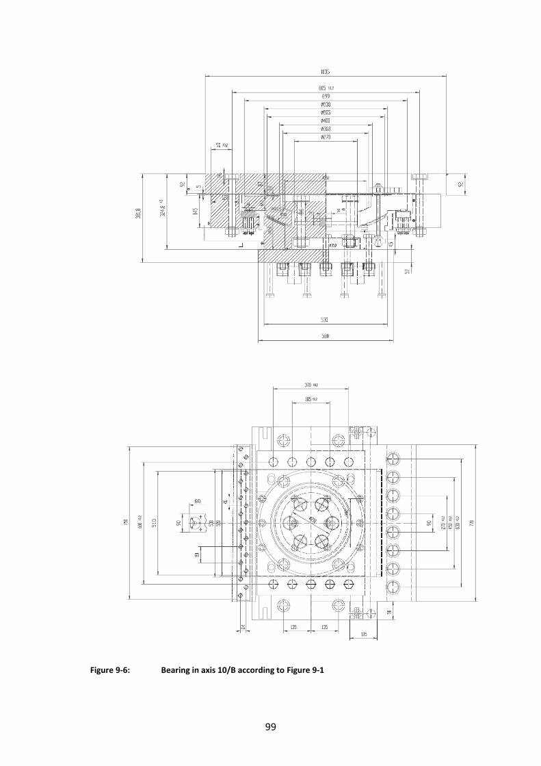
99
Figure 9-6: Bearing in axis 10/B according to Figure 9-1
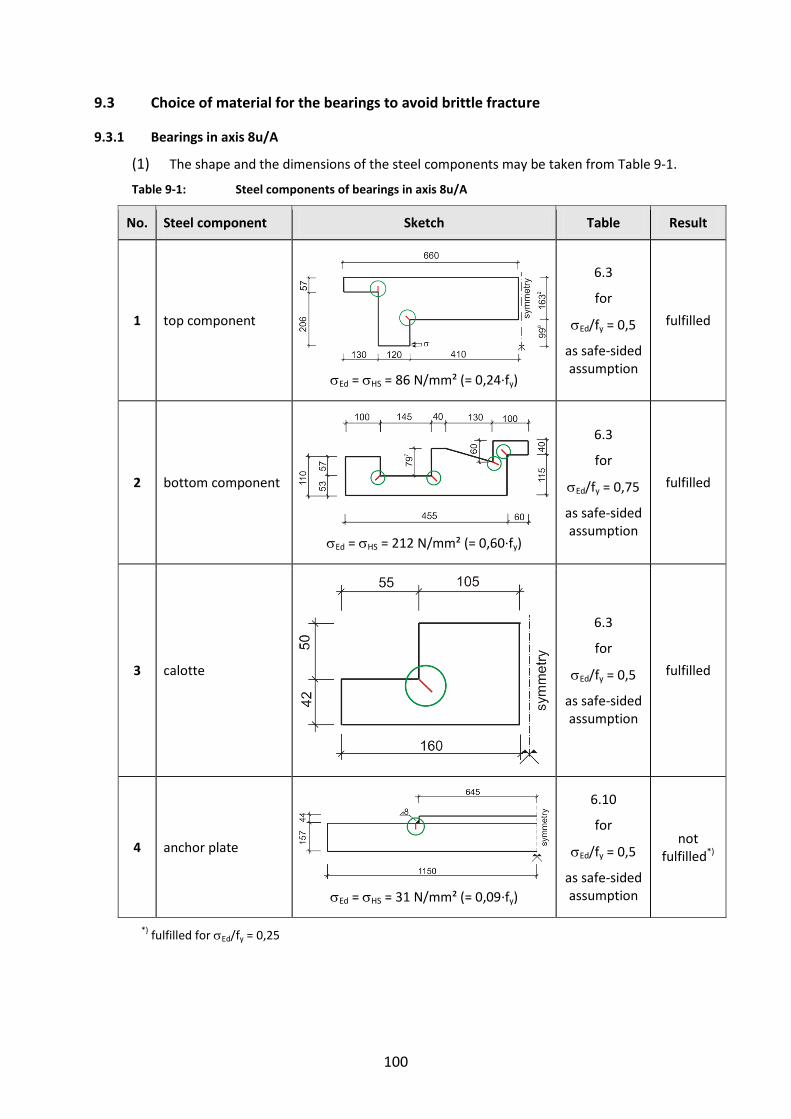
100
9.3 Choice of material for the bearings to avoid brittle fracture
9.3.1 Bearings in axis 8u/A
(1) The shape and the dimensions of the steel components may be taken from Table 9-1.
Table 9-1: Steel components of bearings in axis 8u/A
No. Steel component Sketch Table Result
1 top component
Ed = HS = 86 N/mm² (= 0,24∙fy)
6.3
for
Ed/fy = 0,5
as safe-sided assumption
fulfilled
2 bottom component
Ed = HS = 212 N/mm² (= 0,60∙fy)
6.3
for
Ed/fy = 0,75
as safe-sided assumption
fulfilled
3 calotte
6.3
for
Ed/fy = 0,5
as safe-sided assumption
fulfilled
4 anchor plate
Ed = HS = 31 N/mm² (= 0,09∙fy)
6.10
for
Ed/fy = 0,5
as safe-sided assumption
not fulfilled*)
*) fulfilled for Ed/fy = 0,25

101
9.3.2 Bearings in axis 8u/C
(1) The shape and the dimensions of the steel components may be taken from Table 9-2.
Table 9-2: Steel components of bearings in axis 8u/C
No. Steel component Sketch Table Result
1 top component
Ed = HS = 77 N/mm² (= 0,22∙fy)
6.3
for
Ed/fy = 0,5
as safe-sided assumption
fulfilled
2 bottom component
Ed = HS = 103 N/mm² (= 0,29∙fy)
6.3
for
Ed/fy = 0,5
as safe-sided assumption
fulfilled
3 calotte
6.3
for
Ed/fy = 0,5
as safe-sided assumption
fulfilled
4 anchor plate
Ed = HS = 30 N/mm² (= 0,09∙fy)
6.10
for
Ed/fy = 0,5
as safe-sided assumption
not fulfilled*)
*) fulfilled for Ed/fy = 0,25
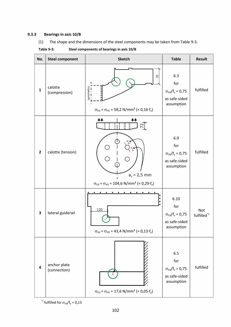
102
9.3.3 Bearings in axis 10/B
(1) The shape and the dimensions of the steel components may be taken from Table 9-3.
Table 9-3: Steel components of bearings in axis 10/B
No. Steel component Sketch Table Result
1 calotte (compression)
Ed = HS = 58,2 N/mm² (= 0,16∙fy)
6.3
for
Ed/fy = 0,75
as safe-sided assumption
fulfilled
2 calotte (tension)
Ed = HS = 104,6 N/mm² (= 0,29∙fy)
6.9
for
Ed/fy = 0,75
as safe-sided assumption
fulfilled
3 lateral guiderail
Ed = HS = 43,4 N/mm² (= 0,13∙fy)
6.10
for
Ed/fy = 0,75
as safe-sided assumption
Not fulfilled*)
4 anchor plate (connection)
Ed = HS = 17,6 N/mm² (= 0,05∙fy)
6.5
for
Ed/fy = 0,75
as safe-sided assumption
fulfilled
*) fulfilled for Ed/fy = 0,13
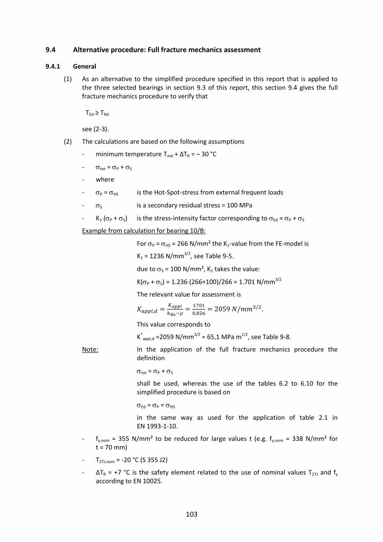
103
9.4 Alternative procedure: Full fracture mechanics assessment
9.4.1 General
(1) As an alternative to the simplified procedure specified in this report that is applied to the three selected bearings in section 9.3 of this report, this section 9.4 gives the full fracture mechanics procedure to verify that
TEd ≥ TRd
see (2-3).
(2) The calculations are based on the following assumptions
- minimum temperature Tmd + ΔTR = – 30 °C
- tot = P + S
- where
- P = HS is the Hot-Spot-stress from external frequent loads
- S is a secondary residual stress = 100 MPa
- K1 (P + S) is the stress-intensity factor corresponding to Ed = P + S
Example from calculation for bearing 10/B:
For P = HS = 266 N/mm² the K1-value from the FE-model is
K1 = 1236 N/mm3/2, see Table 9-5.
due to S = 100 N/mm², K1 takes the value:
K(P + S) = 1.236∙(266+100)/266 = 1.701 N/mm3/2
The relevant value for assessment is
.
This value corresponds to
K*appl,d =2059 N/mm3/2 = 65,1 MPa m1/2, see Table 9-8.
Note: In the application of the full fracture mechanics procedure the definition
tot = P + S
shall be used, whereas the use of the tables 6.2 to 6.10 for the simplified procedure is based on
Ed = P = HS
in the same way as used for the application of table 2.1 in EN 1993-1-10.
- fy,nom = 355 N/mm² to be reduced for large values t (e.g. fy,nom = 338 N/mm² for t = 70 mm)
- T27J,nom = -20 °C (S 355 J2)
- ΔTR = +7 °C is the safety element related to the use of nominal values T27J and fy according to EN 10025.

104
9.4.2 Design value of initial crack
(1) The initial crack sizes a0 and the values a0,d used for the calculation for the various plate-thicknesses are given in Table 9-4:
Table 9-4: Design values for crack-like flaws
steel component axis 8u/A axis 8u/C axis 10/B
t a0 a0,d t a0 a0,d t a0 a0,d
top component 163 2,55 2,60 163 2,55 2,60 70 2,12 2,50
bottom component 53 1,99 2,00 70 2,12 2,50
calotte (tension) 42 1,87 2,00 50 1,96 2,00 72 2,14 2,50
anchor plate 157 2,53 2,60 67 2,56 2,60 57 2,00 2,00
lateral guiderail 120 2,39 2,50
9.4.3 Determination of K1-values from the FE-analysis
(1) For various values Ed = P (0,25 fy, 0,50 fy, 0,75 fy) Table 9-5 gives the K1-values and Keff-values obtained from Finite-Element analysis for the fracture mechanics models given in Table 9-6, Table 9-7, Table 9-8.
Table 9-5: K-values from Finite-Element-Analysis of fracture mechanics models as given in
Table 9-6, Table 9-7 and Table 9-8 for various values Ed/fy = P/fy
No. component
0,25∙fy 0,50∙fy 0,75∙fy
K1 K2 Keff K1 K2 Keff K1 K2 Keff
[N/mm3/2] [N/mm3/2] [N/mm3/2]
1
Ob
erh
afen
Axi
s 8
u/A
top component
1 373 -17 364 746 -35 729 1119 -52 1093
2 325 15 333 650 30 666 975 45 998
2 bottom
component
1 443 15 451 886 30 902 1329 46 1353
2 391 -2 390 782 -4 780 1173 -6 1170
3 541 36 560 1083 71 1120 1624 107 1680
4 211 76 257 422 151 515 633 227 772
3 calotte (tens.)
- 535 -4 533 1071 -9 1066 1606 -13 1600
4 anchor plate - 1063 -306 948 2126 -612 1896 3190 -919 2844
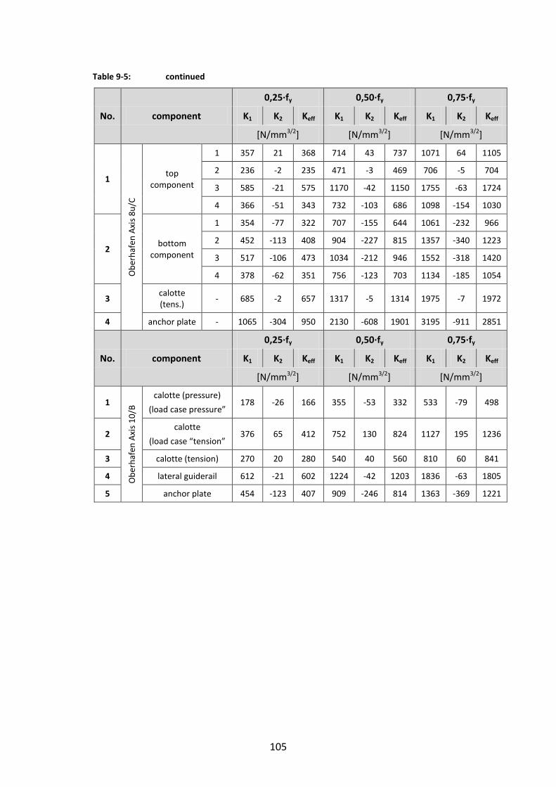
105
Table 9-5: continued
No. component
0,25∙fy 0,50∙fy 0,75∙fy
K1 K2 Keff K1 K2 Keff K1 K2 Keff
[N/mm3/2] [N/mm3/2] [N/mm3/2]
1
Ob
erh
afen
Axi
s 8
u/C
top component
1 357 21 368 714 43 737 1071 64 1105
2 236 -2 235 471 -3 469 706 -5 704
3 585 -21 575 1170 -42 1150 1755 -63 1724
4 366 -51 343 732 -103 686 1098 -154 1030
2 bottom
component
1 354 -77 322 707 -155 644 1061 -232 966
2 452 -113 408 904 -227 815 1357 -340 1223
3 517 -106 473 1034 -212 946 1552 -318 1420
4 378 -62 351 756 -123 703 1134 -185 1054
3 calotte (tens.)
- 685 -2 657 1317 -5 1314 1975 -7 1972
4 anchor plate - 1065 -304 950 2130 -608 1901 3195 -911 2851
No. component
0,25∙fy 0,50∙fy 0,75∙fy
K1 K2 Keff K1 K2 Keff K1 K2 Keff
[N/mm3/2] [N/mm3/2] [N/mm3/2]
1
Ob
erh
afen
Axi
s 1
0/B
calotte (pressure)
(load case pressure” 178 -26 166 355 -53 332 533 -79 498
2 calotte
(load case “tension” 376 65 412 752 130 824 1127 195 1236
3 calotte (tension) 270 20 280 540 40 560 810 60 841
4 lateral guiderail 612 -21 602 1224 -42 1203 1836 -63 1805
5 anchor plate 454 -123 407 909 -246 814 1363 -369 1221

106
Table 9-6: Fracture mechanics assessment for bearing in axis 8u/A for P = 0,50∙fy
No. Steel component Fracture mechanics
model
K*appl,d Tmdr TEd T27J TRd
[MPa∙m1/2
] [°C] [°C] [°C] [°C]
1 Top component
Variant 1
40,5 -30 97 -20 -38
Variant 2
37,3 -30 97 -20 -38
2 Bottom
component
Variant 1
50 -30 33 -20 -12
Variant 2
43,3 -30 47 -20 -12
Variant 3
62,1 -30 5 -20 -12
Variant 4
28,5 -30 97 -20 -12
3 Calotte (tension)
59,4 -30 13 -20 -12
4 Anchor plate
119 -30 -61*) -20 -38*)
*) calculated for Ed/fy = 0,13
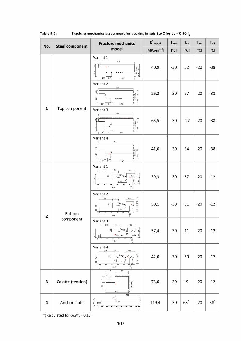
107
Table 9-7: Fracture mechanics assessment for bearing in axis 8u/C for P = 0,50∙fy
No. Steel component Fracture mechanics
model
K*appl,d Tmdr TEd T27J TRd
[MPa∙m1/2
] [°C] [°C] [°C] [°C]
1 Top component
Variant 1
40,9 -30 52 -20 -38
Variant 2
26,2 -30 97 -20 -38
Variant 3
65,5 -30 -17 -20 -38
Variant 4
41,0 -30 34 -20 -38
2 Bottom
component
Variant 1
39,3 -30 57 -20 -12
Variant 2
50,1 -30 31 -20 -12
Variant 3
57,4 -30 11 -20 -12
Variant 4
42,0 -30 50 -20 -12
3 Calotte (tension)
73,0 -30 -9 -20 -12
4 Anchor plate
119,4 -30 63*) -20 -38*)
*) calculated for Ed/fy = 0,13

108
Table 9-8: Fracture mechanics assessment for bearing in axis 10/B for P = 0,75∙fy
No. Steel component Fracture mechanics
model
K*appl,d Tmdr TEd T27J TRd
[MPa∙m1/2
] [°C] [°C] [°C] [°C]
1 Calotte
(compression)
Load case 1 – Tension
Load case 2 – Compression
65,1 -30 -4 -20 -38
28,1 -30 97 -20 -38
2 Calotte
(tension)
Variant 1: Surface cracks located at bore holes
44,2 -30 38 -20 -12
3 Stegeisen
96,9 -30 -44*) -20 -38*)
4 Anchor plate (connection)
Variant 1: Welded connection
71,7 -30 -6 -20 -38
*) calculated for Ed/fy = 0,13
9.4.4 Fracture mechanics assessments
(1) In Table 9-6, Table 9-7 and Table 9-8 the fracture mechanics models used to calculate
the K(P) values and the values K*appl,d including residual stresses S and finally TEd and
TRd are given. The reference stresses are P = 0.50 fy in Table 9-6 and Table 9-7 and
P = 0.75 fy in Table 9-8.
(2) The condition
TEd ≥ TRd
is satisfied for all models except for the anchor plates in 9-6 and Table 9-7 and the lateral guiderail in Table 9-8.
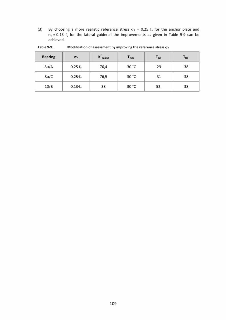
109
(3) By choosing a more realistic reference stress P = 0.25 fy for the anchor plate and
P = 0.13 fy for the lateral guiderail the improvements as given in Table 9-9 can be achieved.
Table 9-9: Modification of assessment by improving the reference stress P
Bearing P K*appl,d Tmdr TEd TRd
8u/A 0,25∙fy 76,4 -30 °C -29 -38
8u/C 0,25∙fy 76,5 -30 °C -31 -38
10/B 0,13∙fy 38 -30 °C 52 -38

110
10 References
[1] DASt-Richtlinie 009: Stahlsortenauswahl für geschweißte Stahlbauten, Deutscher Ausschuss für Stahlbau. Januar 2005.
[2] EN 1993-1-10: Eurocode 3: Design of Steel Structures - Part 1-10: Material Toughness and Through Thickness Properties. 2005.
[3] JRC – Scientific and Technical Report: Commentary and Worked Examples to EN 1993-1-10 “Material Toughness and Through Thickness Properties and Other Toughness Oriented Rules in EN 1993. CRC, September 2008.
[4] JRC – Scientific and Technical Report: Choice of Steel Material to avoid Brittle Fracture for Hollow Section Structures – Addition to EN 1993-1-10. 2011.
[5] EN 1993-1-9: Eurocode 3: Design for Steel Structures - Part 1-9: Fatigue. 2005.
[6] Kühn, B.: Beitrag zur Vereinheitlichung der europäischen Regelungen zur Vermeidung von Sprödbruch. Dissertation, Lehrstuhl für Stahlbau, RWTH Aachen, 2005, Shaker Verlag Aachen, ISBN 3-8322-3901-4.
[7] EN 1337-1: Structural Bearings– Part 1: General Design Rules. 2000.
[8] DIN Fachbericht 101: Einwirkungen auf Brücken. 2009.
[9] EN 1993-2: Eurocode 3 – Design of Steel Structures – Part 2: Steel Bridges. 2006.
[10] Hobbacher, A.: Recommendations for Fatigue Design of Welded Joints and Components. IIW-documentXIII-2151-07/XV-1254-07, 2007.
[11] Marshall, P.W.: Design of Welded Tubular Connections. Basis and Use of AWS Code Provisions. Development in Civil Engineering, 37, Elsevier, 1992. pp. 412.
[12] ASME Boiler and Pressure Vessel Code: Section III, Rule for Construction of Nuclear Power Plant Components, Division 1, Subsection NB, Class 1 Componets. New York, American Society of Mechanical Engineers, 1989.
[13] Dong, P.: A Structural Stress Definition and Numerical Implementation for Fatigue Analysis of Welded Joints. International Journal of Fatigue, Vol. 23, 2001, pp. 865-876.
[14] Dong, P., Hong, J.K., de Jesus, A.M.: Analysis of recent Data using the Structural Stress Procedure in ASME Div 2 Rewrite. Proceedings ASME Pressure Vessel and Piping Conference. PVP2005-71511, New York, ASME, 2005.

111
Annex E to section 9 – Worked Example
Objective
(1) EN 1990 does not give a specific specification for the calculation of design values of action effects as forces, moments and movements relevant for the design of bearings.
(2) It has been left to National Annexes to EN 1990 to give such specifications in the context of the use of the Eurocodes for the design of bridges.
(3) Annex E is the National Annex from Germany. It may be used as an example for such a National Annex. It has been used as reference for preparing the worked example in section 9 - Worked examples - of the JRC-Report “Choice of steel material for bridge bearings to avoid brittle fracture – Addition to EN 1993-1-10”.
Basic requirements for a National Annex to EN 1990 for preparing the technical specifications for bearings
(1) The particular specification for the calculation of design values of action effects on bearings shall take into account the following requirements:
1. It shall be consistently useable for the following cases of analysis of bridges
1. The bridge superstructure can be separated from the substructure at the interface of the bearings and be treated by an independent analysis model.
2. Bridge superstructure and bridge substructure interact by mechanical links provided by the bearings. As a subsequence the bridge superstructure and the bridge substructure form a unique analysis model including the bearings (e.g. for elastomeric bearings).
3. The bridge is an integral bridge without specific bearings.
2. It shall be consistently useable for the design of transition joints.
3. Long term regional experiences with measured data of movements should be
reflected by the rules.
(2) Particular features of the specification for the calculation of design values of action effect on bearings are
- correction of F to be applied to thermal actions from 1.50 to 1.35 (see EN 1990-A1),
- appropriate definition of material properties e.g. for long term effects of concrete or non-metallic material in the bearings.
(3) Annex E is a proposal from the German National Annex to EN 1990-A1 and is considered to comply with these requirements.


European Commission
EUR 25390 EN--- Joint Research Centre --- Institute for the Protection and Security of the Citizen
Title: Choice of steel material for bridge bearings to avoid brittle fracture
Authors: M. Feldmann, B. Eichler, G. Sedlacek, W. Dahl, P. Langerberg, C. Butz, H. Leendertz, G. Hanswille
Editors: A. Pinto, A. Athanasopoulou , H. Amorim-Varum
Luxembourg: Publications Office of the European Union
2012 --- 136 pp. --- 21.0 x 29.7 cm
EUR --- Scientific and Technical Research series --- ISSN 1831-9424 (online), ISSN 1018-5593 (print)
ISBN 978-92-79-25439-0
doi:10.2788/33897
Abstract
Bridge bearings need verification against brittle failure at low temperatures. The design of bearings according to EN 1337 may
lead to structural components with thicknesses no longer covered in the relevant technical construction regulations. Due to its
specific geometry, the loading and stressing and the fabrication process the prerequisites for using the rules in EN 1993-1-10
lead to conservative restrictions or uneconomical choice of steel material. For an economical bearing design further
modifications of the existing rules are necessary. This report adapts the fracture mechanical approach used in EN 1993-1-10
and gives information for a ‘‘safe-sided’’ choice of steel material for bearings. The main modifications refer to the hypothetical
design crack scenario and the definition of the ‘‘nominal design stress’’ at the geometric ‘‘hot-spot’’. An advanced methodology
using Finite Elements and a simplified method using linear bending theory are evaluated.
z
As the Commission’s in-house science service, the Joint Research Centre’s mission is to provide EU policies with independent, evidence-based scientific and technical support throughout the whole policy cycle. Working in close cooperation with policy Directorates-General, the JRC addresses key societal challenges while stimulating innovation through developing new standards, methods and tools, and sharing and transferring its know-how to the Member States and international community. Key policy areas include: environment and climate change; energy and transport; agriculture and food security; health and consumer protection; information society and digital agenda; safety and security including nuclear; all supported through a cross-cutting and multi-disciplinary approach.
LB-NA-25390-EN
-N