Chipsee BCM Debian User Manual
22
Chipsee_BCM_Debian_User_Manual Rev 2.1
Transcript of Chipsee BCM Debian User Manual

Chipsee_BCM_Debian_User_Manual
Rev 2.1

www.chipsee.com
2 / 22 Chipsee_BCM_Debian_User_ManualRev 2.1 CHIPSEE CO., LIMITED
About the Document
History
Revision Date Author Description
2.1 2021-02-25 Chipsee Modify 4G connection
commands
2.0 2021-02-02 Chipsee Add support for
more products
1.0 2020-01-16 Chipsee Initial
Supported Board
CS10600RA070
CS12800RA101-C111
CS10600RA4070
CS12800RA4101-C111
Supported Latest Images
2020-12-02-raspios-buster-armhf-full-chipsee.img.xz
2020-12-02-raspios-buster-armhf-chipsee.img.xz
2020-12-02-raspios-buster-armhf-lite-chipsee.img.xz
www.chipsee.com
CHIPSEE CO., LIMITED Chipsee_BCM_Debian_User_ManualRev 2.1 3 / 22
Contents
About the Document ........................................................................................................................ 2
System Features ................................................................................................................................ 4
1 Prepare ...................................................................................................................................... 5
1.1. Hardware ....................................................................................................................... 5
1.2. Software ........................................................................................................................ 5
2 Debug ........................................................................................................................................ 6
2.1. Serial Debug .................................................................................................................. 6
2.2. SSH Debug ..................................................................................................................... 7
2.3. VNC Debug .................................................................................................................... 9
3 Downloading images ............................................................................................................... 12
3.1. Booting switch configuration ...................................................................................... 12
3.2. Prebuilt image ............................................................................................................. 12
3.3. Writing images to the SD card ..................................................................................... 12
3.4. Writing images to the eMMC ...................................................................................... 13
4 System Resource ..................................................................................................................... 14
4.1. SD Card/USB ................................................................................................................ 14
4.2. Serial Port .................................................................................................................... 14
4.3. GPIO ............................................................................................................................ 16
4.4. Relay ............................................................................................................................ 17
4.5. Buzzer .......................................................................................................................... 18
4.6. Backlight ...................................................................................................................... 18
4.7. 4G ................................................................................................................................ 19
4.8. CAN Bus ....................................................................................................................... 19
4.9. WIFI ............................................................................................................................. 20
4.10. Zigbee ...................................................................................................................... 20
4.11. Camera .................................................................................................................... 20
4.12. Chipsee-init shell ..................................................................................................... 21
Contact Us ....................................................................................................................................... 22

www.chipsee.com
4 / 22 Chipsee_BCM_Debian_User_ManualRev 2.1 CHIPSEE CO., LIMITED
System Features
Feature Comment
Kernel Kernel 5.4.79
System Version * based on raspios 2020-12-02
Python Python 2.7.16 / Python 3.7.3
Qt Needs to be installed by the user
GCC 8.3.0
Debian Version Debian 10 (Buster)
user/password [pi/raspberry]
*The system we used is based on the Raspberry official system; we add Chipsee hardware drivers
to the Raspberry official system. For more information, please refer to:
https://github.com/Chipsee/industrial-pi
www.chipsee.com
CHIPSEE CO., LIMITED Chipsee_BCM_Debian_User_ManualRev 2.1 5 / 22
1 Prepare
1.1. Hardware
⚫ Chipsee Raspberry Pi
⚫ 6V ~ 36V Power Adapter (CS10600RA070 /CS10600RA4070 /CS12800RA101)
⚫ 12V 2A Power Adapter(CS12800RA4101)
⚫ Mini-B USB OTG Cable (CS10600RA070 /CS12800RA101)
⚫ Micro-B USB Cable (CS10600RA4070 /CS12800RA4101)
⚫ USB to RS232 serial cable debug cable, the debug port use RS232 protocol
⚫ SD Card (used for CM3 Lite , CM3+ Lite, CM4 Lite), 16GB at least
CS10600RA070 /CS10600RA4070 /CS12800RA101 need 6V ~ 36V power adapter that does
not come by default. Please make sure you provide the power adapter by yourself.
CS12800RA4101 needs a 12V 2A power adapter that comes with the product. Mini-B and Micro-
B USB OTG Cable is used to download system images to the board with CM3/CM3+/CM4. USB to
RS232 serial cable is used to debug the Chipsee Raspberry Pi product. SD card is used to make a
bootable card. If you use CM3 Lite/CM3 Lite+/CM4 Lite, you also need one SD card, 16GB at least.
1.2. Software
⚫ 7zip
⚫ Prebuilt Images
⚫ balenaEtcher
⚫ rpiboot
⚫ Xshell or other terminal emulation software
⚫ VNC-Viewer
If you need to change the system, you need 7zip/Prebuilt image/balenaEtcher/rpiboot. You
can use Xshell or other terminal emulation software to debug Chipsee Raspberry Pi products in
Windows. You can use VNC-Viewer to control Chipsee Raspberry Pi products over Ethernet.
www.chipsee.com
6 / 22 Chipsee_BCM_Debian_User_ManualRev 2.1 CHIPSEE CO., LIMITED
2 Debug
In this document, we use Xshell to debug the Chipsee Raspberry Pi products. You can also use
other tools such as Putty or another terminal emulation software.
2.1. Serial Debug
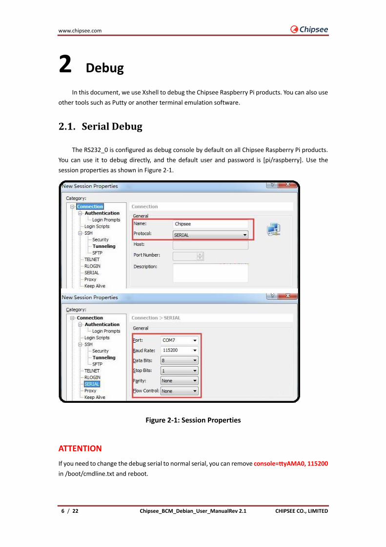
The RS232_0 is configured as debug console by default on all Chipsee Raspberry Pi products.
You can use it to debug directly, and the default user and password is [pi/raspberry]. Use the
session properties as shown in Figure 2-1.
Figure 2-1: Session Properties
ATTENTION
If you need to change the debug serial to normal serial, you can remove console=ttyAMA0, 115200
in /boot/cmdline.txt and reboot.
www.chipsee.com
CHIPSEE CO., LIMITED Chipsee_BCM_Debian_User_ManualRev 2.1 7 / 22
2.2. SSH Debug
Connect Chipsee Raspberry Pi product to the Internet, get the IP address. Then config Xshell
or use ssh tool in the PC directly.
⚫ You need to enable the SSH feature in Chipsee Raspberry Pi product first. Run the
following command in debug console.
$ sudo raspi-config
Interfacing Options -> SSH -> Yes
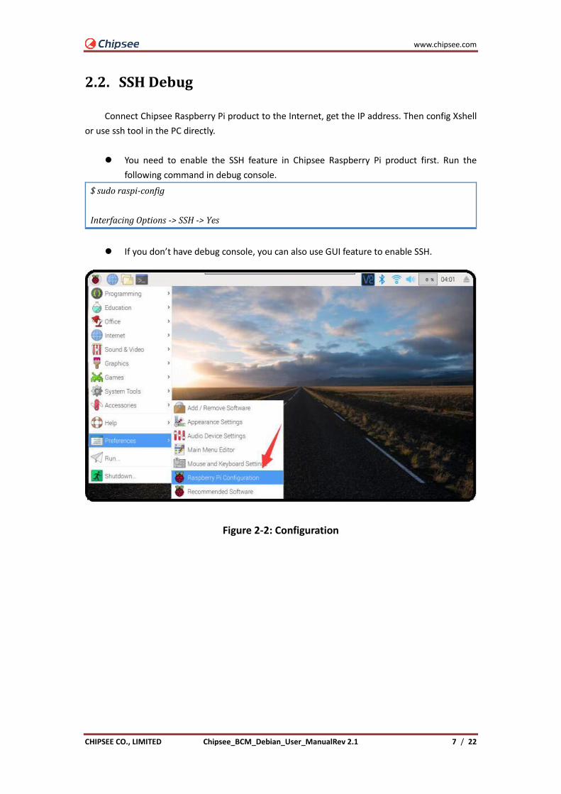
⚫ If you don’t have debug console, you can also use GUI feature to enable SSH.
Figure 2-2: Configuration

www.chipsee.com
8 / 22 Chipsee_BCM_Debian_User_ManualRev 2.1 CHIPSEE CO., LIMITED
Figure 2-3: Configurations SSH
Now we will introduce Xshell ssh debug. First, we need to add a new session and set it like in
Figure 2-4.
Figure 2-4: SSH Setting

www.chipsee.com
CHIPSEE CO., LIMITED Chipsee_BCM_Debian_User_ManualRev 2.1 9 / 22
Figure 2-5 SSH Debug
2.3. VNC Debug
You can use VNC-Viewer in Windows to control Chipsee Raspberry Pi product over Ethernet.
⚫ You need to enable the VNC feature in the Chipsee Raspberry Pi product. Run the
following command in debug console:
$ sudo raspi-config
Interfacing Options -> VNC -> Yes
⚫ If you don’t have debug console, you can also use GUI feature to enable VNC.

www.chipsee.com
10 / 22 Chipsee_BCM_Debian_User_ManualRev 2.1 CHIPSEE CO., LIMITED
Figure 2-6: Configurations
Figure 2-7: VNC Configuration
⚫ Use VNC-Viewer in Windows to control it over Ethernet, as shown in Figures 2-8, 2-9, and
2-10.
Figure 2-8: Connecting Vnc-Viewer

www.chipsee.com
CHIPSEE CO., LIMITED Chipsee_BCM_Debian_User_ManualRev 2.1 11 / 22
Figure 2-9: Authentication
Figure 2-10: VNC Desktop

www.chipsee.com
12 / 22 Chipsee_BCM_Debian_User_ManualRev 2.1 CHIPSEE CO., LIMITED
3 Downloading images
3.1. Booting switch configuration
Chipsee Raspberry Pi products support SD boot and eMMC boot (CS12800RA4101 only
supports eMMC boot). It is based on your CM version. If you use CM with eMMC, you can only use
eMMC boot. If you use CM Lite which has no eMMC, you can only use SD boot. The SD card should
be placed in SD0 slot. The SD1 slot is used as external storage.
As to CS10600RA070 /CS12800RA101 /CS10600RA4070
When you need to download a new system to eMMC, you should configure the boot switch to USB
position and insert Mini-B USB cable first, then power the board. This will enable eMMC to work
as a USB storage. After the eMMC flash, you need to configure the boot switch to the eMMC
position again.
When you need to use SD boot, you should configure the boot switch to the eMMC position.
As to CS12800RA4101
When you need to download a new system to eMMC, you should insert a Micro-B USB cable and
press the power button first, then power the board to enable eMMC to work as a USB storage. Find
detailed steps in the following text.
3.2. Prebuilt image
Chipsee Raspberry Pi products use the Raspberry Pi official system as a base and add some
modules and drivers. You can get the driver and latest image from the following link:
https://github.com/Chipsee/industrial-pi
If you're not using balenaEtcher, you'll need to unzip .img.xz file and get the image file (.img) to
write to your SD card.
3.3. Writing images to the SD card
Before you start, don't forget to check your SD card size (at least 16GB).
You will need to use an image writing tool to install the image you have downloaded on your SD
card.
balenaEtcher is a graphical SD card writing tool that works on Mac OS, Linux and Windows, and is
the easiest option for most users. balenaEtcher also supports writing images directly from
the .img.xz file, without any unzipping required. To write your image with balenaEtcher:
Download the latest version of balenaEtcher and install it.
⚫ Connect an SD card reader to the SD card inside.
⚫ Open balenaEtcher and select from your hard drive the Raspberry Pi .img.xz file you want
to write to the SD card.
www.chipsee.com
CHIPSEE CO., LIMITED Chipsee_BCM_Debian_User_ManualRev 2.1 13 / 22
⚫ Select the SD card you want to write your image to.
⚫ Review your selections and click 'Flash!' to begin writing data to the SD card.
Note: for Linux users, zenity might need to be installed on your machine for balenaEtcher to be
able to write the image on your SD card.
3.4. Writing images to the eMMC
Before you start, don’t forget to check your eMMC size, and select one image. You also need
to install rpitools to enable eMMC to work as one USB storage in your PC.
Under Windows, an installer is available to install the required drivers and boot tool automatically.
For those who just want to enable the Compute Module eMMC as a mass storage device under
Windows, the stand-alone installer is the recommended option. The installer is rpitools.
⚫ Download and run the Windows installer rpitools to install the drivers and boot tool.
As to CS10600RA070 /CS12800RA101 /CS10600RA4070
⚫ Plug your host PC Mini-B USB into the USB Downloader port, making sure the boot switch
is set to the USB position.
As to CS12800RA4101
⚫ Plug your host PC Micro-B USB into the USB Slave port (can be also called USB Download
Port), press the power button and keep it pressed.
⚫ Apply power to the board; Windows should now find the hardware and install the driver.
For CS12800RA4101, you can release the power button now.
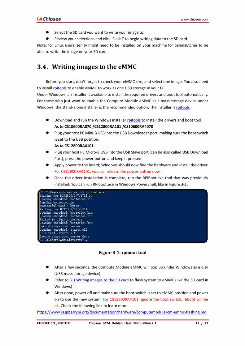
⚫ Once the driver installation is complete, run the RPiBoot.exe tool that was previously
installed. You can run RPiBoot.exe in Windows PowerShell, like in Figure 3-1.
Figure 3-1: rpiboot tool
⚫ After a few seconds, the Compute Module eMMC will pop up under Windows as a disk
(USB mass storage device).
⚫ Refer to 3.3 Writing images to the SD card to flash system to eMMC (like the SD card in
Windows)
⚫ After done, power off and make sure the boot switch is set to eMMC position and power
on to use the new system. For CS12800RA4101, ignore the boot switch, reboot will be
ok. Check the following link to learn more:
https://www.raspberrypi.org/documentation/hardware/computemodule/cm-emmc-flashing.md
www.chipsee.com
14 / 22 Chipsee_BCM_Debian_User_ManualRev 2.1 CHIPSEE CO., LIMITED
4 System Resource
4.1. SD Card/USB
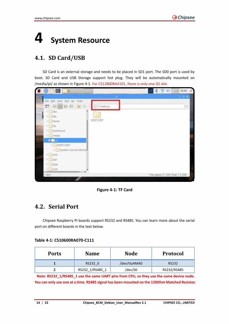
SD Card is an external storage and needs to be placed in SD1 port. The SD0 port is used by
boot. SD Card and USB Storage support hot plug. They will be automatically mounted on
/media/pi/ as shown in Figure 4-1. For CS12800RA4101, there is only one SD slot.
Figure 4-1: TF Card
4.2. Serial Port
Chipsee Raspberry Pi boards support RS232 and RS485. You can learn more about the serial
port on different boards in the text below.
Table 4-1: CS10600RA070-C111
Ports Name Node Protocol
1 RS232_0 /dev/ttyAMA0 RS232
2 RS232_1/RS485_1 /dev/S0 RS232/RS485
Note: RS232_1/RS485_1 use the same UART pins from CPU, so they use the same device node.
You can only use one at a time. RS485 signal has been mounted on the 120Ohm Matched Resistor.

www.chipsee.com
CHIPSEE CO., LIMITED Chipsee_BCM_Debian_User_ManualRev 2.1 15 / 22
There is one GPIO which is used by RS485. You can control it to enable and disable RS485 send and
receive. Check the tables below.
Table 4-2: RS485 control GPIO
GPIO Initial Control Function
GPIO34
$ echo 34 > /sys/class/gpio/export
$ echo out > /sys/class/gpio/gpio34/direction
$ ln -s /sys/class/gpio/gpio34/value /dev/rs485con
$echo 1 > /dev/rs485con Enable send
Disable receive
$echo 0 > /dev/rs485con Enable receive
Disable send
Table 4-3: CS12800RA101
Ports Name Node Protocol
1 CPU_RS232_0 /dev/ttyAMA0 RS232
2 CPU_RS232_1 /dev/S0 RS232
3 RS232_1 /dev/ttyUSB0 RS232
4 RS232_2 /dev/ttyUSB1 RS232
5 RS485_3 /dev/ttyUSB2 RS485
6 RS485_4 /dev/ttyUSB3 RS485
Table 4-4: CS10600RA4070-C111
Ports Name Node Protocol
1 RS232_0 /dev/ttyAMA0 RS232
2 RS232_2 /dev/ttyAMA1 RS232
3 RS232_3 /dev/ttyAMA2 *
4 RS485_3 /dev/ttyAMA2 RS485
5 RS232_5 /dev/ttyAMA3 *
6 RS485_5 /dev/ttyAMA3 RS485
*These two channels are not used by default and can be configured to RS232. In this case port 4
and port 6 will be disabled. Feel free to contact us if you need different settings from the default
one.

www.chipsee.com
16 / 22 Chipsee_BCM_Debian_User_ManualRev 2.1 CHIPSEE CO., LIMITED
Table 4-5: CS12800RA4101
Ports Name Node Protocol
1 RS232_0 /dev/ttyAMA0 RS232
2 RS232_1 /dev/ttyAMA1 RS232
3 RS485_2 /dev/ttyAMA2 RS485
You can install “cutecom” to test the serial port:
$ sudo apt-get install cutecom
Only root user and use the serial port:
$ sudo cutecom
4.3. GPIO
There are 8 GPIOs, 4 Output and 4 Input, they are all isolated. You can control the output or
input pin voltage by feeding the VDD_ISO suite voltage. You can select 5V~24V. Refer to the tables
below for a detailed port definition:
Table 4-6: CS10600RA070 P19 Port
Pin Number GPIO Number Function Device Node
1 GPIO11 IN4 /dev/chipsee-gpio8
2 GPIO10 IN3 /dev/chipsee-gpio7
3 GPIO9 IN2 /dev/chipsee-gpio6
4 GPIO8 IN1 /dev/chipsee-gpio5
5 GPIO7 OUT4 /dev/chipsee-gpio4
6 GPIO6 OUT3 /dev/chipsee-gpio3
7 GPIO5 OUT2 /dev/chipsee-gpio2
8 GPIO4 OUT1 /dev/chipsee-gpio1
9 GND_ISO Isolated GND NC
10 VDD_ISO Isolated VDD(5V-24V) NC
www.chipsee.com
CHIPSEE CO., LIMITED Chipsee_BCM_Debian_User_ManualRev 2.1 17 / 22
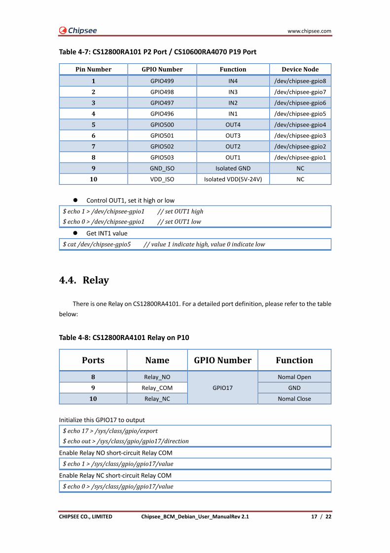
Table 4-7: CS12800RA101 P2 Port / CS10600RA4070 P19 Port
Pin Number GPIO Number Function Device Node
1 GPIO499 IN4 /dev/chipsee-gpio8
2 GPIO498 IN3 /dev/chipsee-gpio7
3 GPIO497 IN2 /dev/chipsee-gpio6
4 GPIO496 IN1 /dev/chipsee-gpio5
5 GPIO500 OUT4 /dev/chipsee-gpio4
6 GPIO501 OUT3 /dev/chipsee-gpio3
7 GPIO502 OUT2 /dev/chipsee-gpio2
8 GPIO503 OUT1 /dev/chipsee-gpio1
9 GND_ISO Isolated GND NC
10 VDD_ISO Isolated VDD(5V-24V) NC
⚫ Control OUT1, set it high or low
$ echo 1 > /dev/chipsee-gpio1 // set OUT1 high
$ echo 0 > /dev/chipsee-gpio1 // set OUT1 low
⚫ Get INT1 value
$ cat /dev/chipsee-gpio5 // value 1 indicate high, value 0 indicate low
4.4. Relay
There is one Relay on CS12800RA4101. For a detailed port definition, please refer to the table
below:
Table 4-8: CS12800RA4101 Relay on P10
Ports Name GPIO Number Function
8 Relay_NO
GPIO17
Nomal Open
9 Relay_COM GND
10 Relay_NC Nomal Close
Initialize this GPIO17 to output
$ echo 17 > /sys/class/gpio/export
$ echo out > /sys/class/gpio/gpio17/direction
Enable Relay NO short-circuit Relay COM
$ echo 1 > /sys/class/gpio/gpio17/value
Enable Relay NC short-circuit Relay COM
$ echo 0 > /sys/class/gpio/gpio17/value

www.chipsee.com
18 / 22 Chipsee_BCM_Debian_User_ManualRev 2.1 CHIPSEE CO., LIMITED
4.5. Buzzer
The Chipsee Raspberry Pi boards have one buzzer. We have created one symbol link to
/dev/buzzer. You can control it as follows:
$ echo 1 > /dev/buzzer //enable buzzer
$ echo 0 > /dev/buzzer // disable buzzer
4.6. Backlight
We use one GPIO to control the backlight for Chipsee Raspberry Pi boards, the GPIO is
different for different boards. Find more details below.
Table 4-9: Backlight GPIO
Board GPIO GPIO Config in config.txt PWM PWM Func
CS10600RA070 41 gpio=41=op,dh Pwm1 4
CS12800RA101 41 gpio=41=op,dh Pwm1 4
CS10600RA4070 18 gpio=18=op,dh Pmw0 2
CS12800RA4101 13 gpio=13=op,dh Pwm1 4
We use gpio=<GPIO>=op,dh in /boot/config.txt to enable the backlight by default. You can open
and close backlight as follows. GPIO41 is used as an example:
$ echo 41 > /sys/class/gpio/export
$ echo out > /sys/class/gpio/gpio41/direction
$ echo 1 > /sys/class/gpio/gpio41/value //enable backlight
$ echo 0 > /sys/class/gpio/gpio41/value //disable backlight
If you want to use PWM to control the backlight, you need to remove gpio=<GPIO >=op,dh, and
add dtoverlay=pwm, pin=<GPIO>, func=<PWM Func> in /boot/config.txt. You can do it in the
following way. GPIO13 is used as an example.
Remove this line in /boot/config.txt:
gpio=13=op,dh
And add the following line to /boot/config.txt:
dtoverlay=pwm,pin=13,func=4
Reboot, after that, Config and enable pwm
$ cd /sys/class/pwm/pwmchip0/
$ echo 1 > export //GPIO13 is pwm1, so we use 1
$ echo 10000000 > pwm1/period //set period to 10ms,100Hz
$ echo 8000000 > pwm1/duty_cycle // set duty to 8ms
$ echo 1 > pwm1/enable // enable pwm1
www.chipsee.com
CHIPSEE CO., LIMITED Chipsee_BCM_Debian_User_ManualRev 2.1 19 / 22
4.7. 4G
You can use 4G on Chipsee Raspberry Pi products. If the 4G module is Quectel EC20, you can
use the following tools to connect to internet.
$ sudo install udhcpc
$ sudo ifconfig wwan0 down
$ sudo quectel-CM –s 3gnet / cmnet / ctnet & // select different network base on your SIM
card, 3gnet is used by China-unicom and cmnet is used by China-mobile, ctnet is used by China
Telecom
If you use EC20 with GPS function, you can enable and get data in the following way.
Open one terminal to catch data:
cat /dev/ttyUSB1
Open another terminal to config and enable:
$ microcom –s 9600 /dev/ttyUSB2
AT+QGPSCFG=”gpsnmeatype”,1
AT+QGPS=1 // enable GPS, wait some minutes, you can get date from fist terminal.
AT+QGPSEND // disable GPS
Don’t forget to use one GPS ANT.
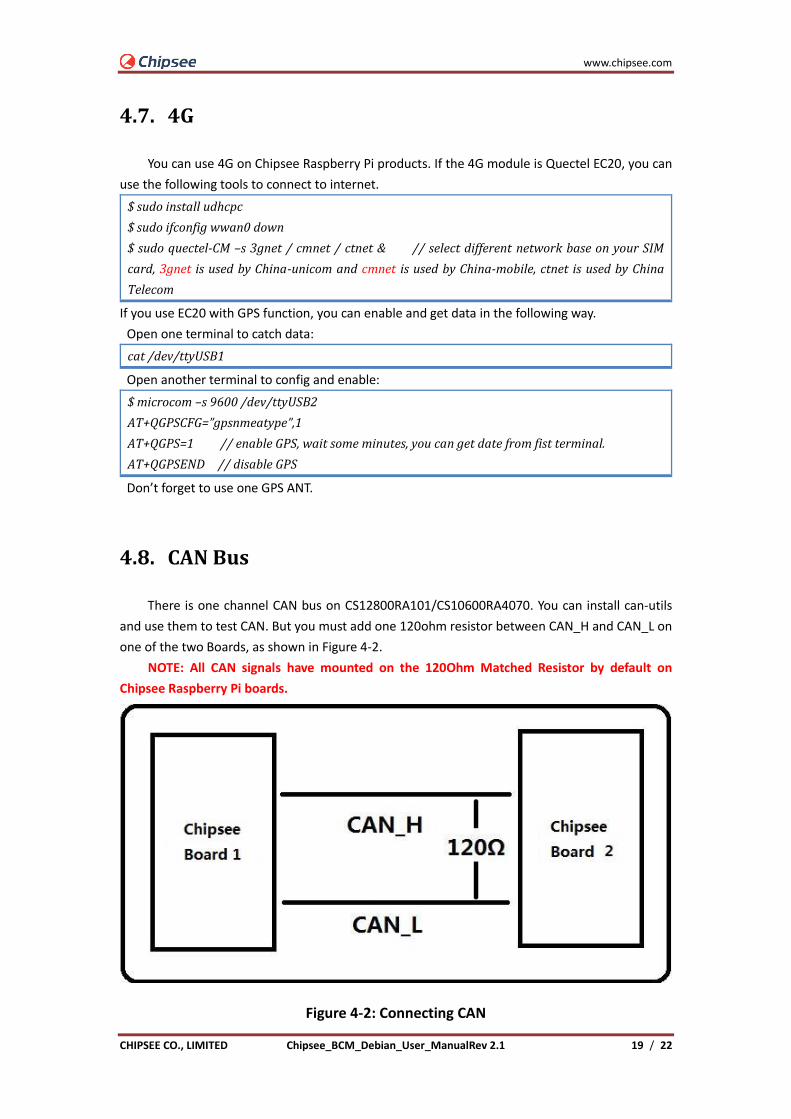
4.8. CAN Bus
There is one channel CAN bus on CS12800RA101/CS10600RA4070. You can install can-utils
and use them to test CAN. But you must add one 120ohm resistor between CAN_H and CAN_L on
one of the two Boards, as shown in Figure 4-2.
NOTE: All CAN signals have mounted on the 120Ohm Matched Resistor by default on
Chipsee Raspberry Pi boards.
Figure 4-2: Connecting CAN

www.chipsee.com
20 / 22 Chipsee_BCM_Debian_User_ManualRev 2.1 CHIPSEE CO., LIMITED
Here are a few examples to test CAN by using CAN units.
Install can-utils
$ sudo apt install can-utils
⚫ Set the bit-rate to 50Kbits/sec with triple sampling using the following command (use
ROOT user):
$ sudo ip link set can0 type can bitrate 50000 triple-sampling on
⚫ Bring up the device using the command:
$ sudo ip link set can0 up
⚫ Transfer packets
a. Transmit 8 bytes with standard packet id number as 0x10
$ sudo cansend can0 -i 0x10 0x11 0x22 0x33 0x44 0x55 0x66 0x77 0x88
b. Transmit 8 bytes with extended packet id number as 0x800
$ sudo cansend can0 -i 0x800 0x11 0x22 0x33 0x44 0x55 0x66 0x77 0x88 -
e
c. Transmit 20 8 bytes with extended packet id number as 0xFFFFF
$ sudo cansend can0 -i 0xFFFFF 0x11 0x22 0x33 0x44 0x55 0x66 0x77
0x88 -e --loop=20
⚫ Receive data from CAN bus
$ sudo candump can0
⚫ Bring down the device
$ sudo ip link set can0 down
4.9. WIFI
The Chipsee Raspberry Pi boards support RTL8723BU/RTL8723DU chip Wi-Fi. The
CS10600RA070/CS12800RA101 have an onboard RTL8723BU Wi-Fi chip. The
CS10600RA4070/CS12800RA4101 have no onboard Wi-Fi by default so you can use the USB Wi-Fi
dongle to enable the Wi-Fi.
4.10. Zigbee
The CS10600RA4070/CS12800RA4101 boards have an onboard ZigBee chip CC2531. Its device
node in the system is /dev/ttyACM0. We use zigbee2mqtt project firmware by default. Check the
following link to learn more about this project: https://www.zigbee2mqtt.io
4.11. Camera
The camera port CAM is compatible with Raspberry pi. Please refer to the following link to
learn how to attach a camera.
https://www.raspberrypi.org/documentation/hardware/computemodule/cmio-camera.md

www.chipsee.com
CHIPSEE CO., LIMITED Chipsee_BCM_Debian_User_ManualRev 2.1 21 / 22
4.12. Chipsee-init shell
We use one chipsee-init.sh as an initial shell which is placed in /opt/chipsee/chipsee-init.sh.
We initialize the GPIO/Buzzer and other configs in it. If you want to change it, please be careful.
Do a backup first before you modify anything.
www.chipsee.com
22 / 22 Chipsee_BCM_Debian_User_ManualRev 2.1 CHIPSEE CO., LIMITED
Contact Us
CHIPSEE CO., LIMITED
Xinyuan Science Park B406, 97 Changping Road, Changping District
Beijing, 102206, China
TEL:+86-10-62561127
Web: www.chipsee.com
E-Mail: [email protected]