Chip-on-Glass LCD Driver Technology - nxp.com · Chip-on-Glass LCD Driver Technology “Chip on...
9
Chip-on-Glass LCD Driver Technology Executive Summary Progress in Liquid Crystal Display (LCD) medical imaging technology has led to its increasing adoption for diagnostic viewing of medical images. Although LCD monitors have many advantages over cathode-ray tube monitors, cost continues to be a factor when medical professionals choose equipment. The rising overall cost of medical care adds further urgency to decrease equipment cost where possible. For systems that require LCD displays, a typical design approach has been to mount the display glass as well as the integrated circuit driving the display directly onto a printed circuit board (PCB). This approach results in a complex and area-intense PCB design. To address this issue, NXP has developed a Chip-on-Glass (COG) LCD driver approach whereby the integrated circuit mounts directly on the display glass, with the overall impact being a reduction in system cost. COG is a very reliable and well- established technology, which is often used in the automobile industry. Use of LCD Displays in Medical Imaging The need for imagery displays in medicine is vast, with technology such as digital X-ray, CT, MRI, and ultrasound just a few examples. Technologi- cal advances in areas such as minimally invasive surgery, where imaging provides doctors guidance also drive more display use. As LCD technology continues to progress and improve, digital imaging techniques are replacing analog-based cathode-ray tube monitors for medical uses. LCD monitors have many advantages over CRTs, including sharper imagery, reduced eyestrain, longer life, space efficiency, energy efficiency, reduced radiation, lighter weight, and better overall product quality. The one draw- back to rapid and widespread adoption has been cost. Pressure to reduce cost also increases as device portability requirements grow. Portable devices enable more efficient use of medical resources, and can even enable in-home care. To make a portable device feasible for in-home use, however, it must be offered at a reasonable price point. Thus manufacturers must find ways to cut cost wherever possible. One way to cut cost is by an innovative LCD design technology called Well-proven Approach from NXP Reduces Medical System Design Costs Executive Summary 1 Use of LCD Displays in Medical Imaging 1 The Chip-on-Glass Value Proposition 2 Understanding the Conventional Surface Mount Method 2 The Alternative Chip-on-Glass Concept 3 Comparing Design Effort Associated with COD and SMD Approaches 4 Cost Benefits of the COG Solutions versus the SMD Approach 5 Example Case for Cost Comparison 6 References 9 Acronyms 9
Transcript of Chip-on-Glass LCD Driver Technology - nxp.com · Chip-on-Glass LCD Driver Technology “Chip on...

Chip-on-Glass LCD Driver Technology
Executive SummaryProgress in Liquid Crystal Display (LCD) medical imaging technology has led to its increasing adoption for diagnostic viewing of medical images. Although LCD monitors have many advantages over cathode-ray tube monitors, cost continues to be a factor when medical professionals choose equipment. The rising overall cost of medical care adds further urgency to decrease equipment cost where possible.
For systems that require LCD displays, a typical design approach has been to mount the display glass as well as the integrated circuit driving the display directly onto a printed circuit board (PCB). This approach results in a complex and area-intense PCB design. To address this issue, NXP has developed a Chip-on-Glass (COG) LCD driver approach whereby the integrated circuit mounts directly on the display glass, with the overall impact being a reduction in system cost. COG is a very reliable and well-established technology, which is often used in the automobile industry.
Use of LCD Displays in Medical ImagingThe need for imagery displays in medicine is vast, with technology such as digital X-ray, CT, MRI, and ultrasound just a few examples. Technologi-cal advances in areas such as minimally invasive surgery, where imaging provides doctors guidance also drive more display use. As LCD technology continues to progress and improve, digital imaging techniques are replacing
analog-based cathode-ray tube monitors for medical uses. LCD monitors have many advantages over CRTs, including sharper imagery, reduced eyestrain, longer life, space efficiency, energy efficiency, reduced radiation, lighter weight, and better overall product quality. The one draw-back to rapid and widespread adoption has been cost.
Pressure to reduce cost also increases as device portability requirements grow. Portable devices enable more efficient use of medical resources, and can even enable in-home care. To make a portable device feasible for in-home use, however, it must be offered at a reasonable price point. Thus manufacturers must find ways to cut cost wherever possible. One way to cut cost is by an innovative LCD design technology called
Well-proven Approach from NXP Reduces Medical System Design Costs
Executive Summary 1Use of LCD Displays in Medical Imaging 1The Chip-on-Glass Value Proposition 2Understanding the Conventional Surface Mount Method 2The Alternative Chip-on-Glass Concept 3Comparing Design Effort Associated with COD and SMD Approaches 4Cost Benefits of the COG Solutions versus the SMD Approach 5Example Case for Cost Comparison 6References 9Acronyms 9
Chip-on-Glass LCD Driver Technology
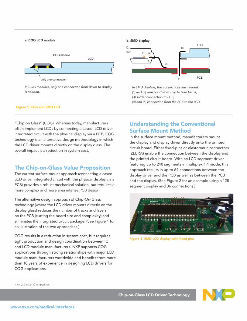
“Chip on Glass” (COG). Whereas today, manufacturers often implement LCDs by connecting a cased1 LCD driver integrated circuit with the physical display via a PCB, COG technology is an alternative design methodology in which the LCD driver mounts directly on the display glass. The overall impact is a reduction in system cost.
The Chip-on-Glass Value Proposition The current surface mount approach (connecting a cased LCD driver integrated circuit with the physical display via a PCB) provides a robust mechanical solution, but requires a more complex and more area intense PCB design.
The alternative design approach of Chip-On-Glass technology (where the LCD driver mounts directly on the display glass) reduces the number of tracks and layers on the PCB (cutting the board size and complexity) and eliminates the integrated circuit package. (See Figure 1 for an illustration of the two approaches.)
COG results in a reduction in system cost, but requires tight production and design coordination between IC and LCD module manufacturers. NXP supports COG applications through strong relationships with major LCD module manufacturers worldwide and benefits from more than 10 years of experience in designing LCD drivers for COG applications.
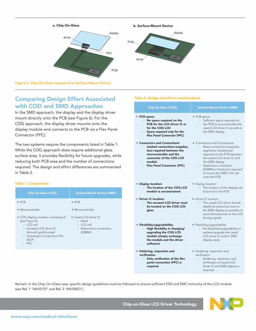
Understanding the Conventional Surface Mount MethodIn the surface mount method, manufacturers mount the display and display driver directly onto the printed circuit board. Either fixed-pins or elastomeric connectors (ZEBRA) enable the connection between the display and the printed circuit board. With an LCD segment driver featuring up to 240 segments in multiplex 1:4 mode, this approach results in up to 64 connections between the display driver and the PCB as well as between the PCB and the display. (See Figure 2 for an example using a 128 segment display and 36 connections.)
Figure 2. SMD LCD display with fixed pins
www.nxp.com/medical-interfaces
1. An LCD driver IC in a package.
IC chip (1) (2)
(3)
(4)
(5)LCD
PCB013aaa515
SMD display
013aaa516only one connection
COG moduleLCD
In SMD displays, five connections are needed:
(1) and (2) wire bond from chip to lead frame,
(3) solder connection to PCB,
(4) and (5) connection from the PCB to the LCD.
In COG modules, only one connection from driver to display
is needed.
b. SMD displaya. COG LCD module
Figure 1. COG and SMD LCD

Figure 3 illustrates the construction of an SMD LCD with elastomeric connectors (ZEBRA). The SMD display consists of the LCD cell and a metal or plastic bezel that clamps the LCD cell down onto the elastomeric connector (ZEBRA), which then makes the contact with the tracks on the PCB. The ZEBRA connector is composed of fine pitch conductive segments alternating with isolating segments, embedded between two isolating strips. The metal or plastic bezel squeezes the ZEBRA slightly to guarantee a firm contact between the LCD and the PCB.
Metal or plastic bezel, to clamp down the LCD cell
ZEBRA: elastomeric silicone connector making contact with the tracks (usually gold plated) on the PCB.
Printed Circuit Board (PCB)
Figure 3. Illustration of an SMD LCD with elastomeric connector
The Alternative Chip-on-Glass ConceptA Chip-on-Glass LCD module consists of:
• A display glass that represents the active display area. • A seal ring around the display glass that protects and
seals the display glass. • A contact ledge to supply room for the LCD driver IC.
The LCD driver IC itself generates the display control and driving signals. A Flex Panel Connector (FPC) connects the display driver IC to the system microcontroller (see Figure 4).
Liquid crystal displays are created by sandwiching liquid crystal between two glass substrate plates. To create a COG module, one of the two glass plates that make up the LCD is extended to give room for mounting an LCD driver and providing connections to it (see Figure 4 and Figure 5). Indium Tin Oxide (ITO) electrodes, which are integrated on the surface of the glass plates, connect via an Anisotropic Conductive Film (ACF) to the gold bumps mounted on the connecting pads of the driver IC to enable the display connections.
Seal ring round the display glass
Active display area
Contact ledge
LCD driver/controller
Flex panel connector
013aaa514Figure 4. COG LCD module
chip
anisotropic conductive film
ITO
glass
LCD cell epoxy underfill
silver dot
gold bumps
Figure 5. Illustration of a COG LCD module
The COG approach increases design flexibility for the LCD module in a number of ways:
• For COG, an uncased display driver IC (display driver without a package) is sufficient; the only requirements are that the display driver IC has gold bumps to enable the contact to the indium tin oxide tracks on the LCD glass.
• The placement of the LCD driver IC can be on any side of the active display area. This flexibility allows placement of the LCD driver IC on the smaller side to minimize the required contact ledge area, which reduces cost.
• The COG technology allows the cascading of several LCD driver ICs directly on the contact ledge in order to support driving larger display resolutions.
• COG technology allows for connecting the display to the PCB wherever it is most suitable, even some distance away from the microcontroller.
Chip-on-Glass LCD Driver Technology
www.nxp.com/medical-interfaces
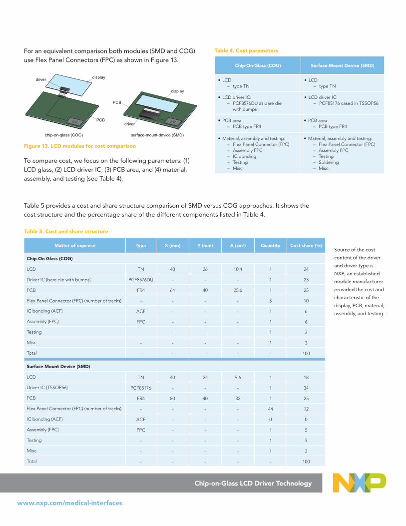
Comparing Design Effort Associated with COD and SMD ApproachesIn the SMD approach, the display and the display driver mount directly onto the PCB (see Figure 6). For the COG approach, the display driver mounts onto the display module and connects to the PCB via a Flex Panel Connector (FPC).
The two systems require the components listed in Table 1. While the COG approach does require additional glass surface area, it provides flexibility for future upgrades, while reducing both PCB area and the number of connections required. The design and effort differences are summarized in Table 2.
Table 1. Components
Chip-On-Glass (COG) Surface-Mount Device (SMD)
• PCB • PCB
• Microcontroller • Microcontroller
• COG display module, consisting of (see Figure 5):
– LCD cell – Uncased LCD driver IC
(die with gold bumps) – Anisotropic Conductive Film
(ACF) – FPC
• Cased LCD driver IC – Bezel – LCD cell – Elastomeric connectors
(ZEBRA)
Table 2. Design and effort considerations
Chip-On-Glass (COG) Surface-Mount Device (SMD)
• PCB space: – No space required on the
PCB for the LCD driver IC or for the COG LCD
– Space required only for the Flex Panel Connector (FPC)
• PCB space: – Sufficient space required on
the PCB to accommodate the cased LCD driver IC as well as the SMD display
• Connectors and Connections: – Limited connections (supplies,
bus) required between the microcontroller and the connector of the COG LCD module
– Flex Panel Connector (FPC)
• Connectors and Connections: – Many connections (supplies,
segments, backplanes) required on the PCB between the cased LCD driver IC and the SMD display
– Elastomeric connector (ZEBRA) or fixed pins required to mount the SMD LCD cell onto the PCB
• Display location: – The location of the COG LCD
module is unconstrained
• Display location: – The location of the display cell
is bound to the PCB
• Driver IC location: – The uncased LCD driver must
be located on the COG LCD glass
• Driver IC location: – The cased LCD driver should
ideally be placed as close to the SMD display as possible to avoid disturbances on the LCD driving signals
• Flexibility/upgradability: – High flexibility in changing/
upgrading the COG LCD module (simply exchange the module and the driver software)
• Flexibility/upgradability: – No flexibility/upgradability to
replace/upgrade the cased LCD driver IC and/or SMD display easily
• Soldering, inspection and verification:
– Only verification of the flex panel connection (FPC) is required
• Soldering, inspection and verification:
– Soldering, inspection and verification of cased LCD driver IC and SMD display is required
Chip-on-Glass LCD Driver Technology
www.nxp.com/medical-interfaces
displaydriver
chip-on-glass (COG)
PCBµC
FPC
display
driver
surface-mount-device (SMD)
PCB
µC
Figure 6. Chip-On-Glass compared to Surface-Mount Device
b. Surface-Mount Devicea. Chip-On-Glass
Remark: In the Chip-On-Glass case, specific design guidelines must be followed to ensure sufficient ESD and EMC immunity of the LCD module
(see Ref. 1 “AN10170” and Ref. 3 “AN10853”).

Cost Benefits of the COG Solutions versus the SMD ApproachFour key components2 determine the cost of a COG or SMD display. These components include:
• Printed circuit board• LCD driver• Display glass• Material and assembly
The following examines each of these contributing components in more detail, and Table 3 provides a cost comparison summary for the two approaches.
Table 3. Key Components Cost Comparison Summary
Chip-On-Glass (COG) Surface-Mount Device (SMD)
• Less complex and likely smaller PCB • More complex and likely larger PCB
• Uncased LCD driver (die with gold bumps) is sufficient
• Cased LCD driver (with package) required
• Only soldering, inspection and verification of the connector to the COG LCD module required
• Soldering, inspection and verification of the LCD driver and the SMD display required
• Larger LCD glass required to accom-modate the uncased LCD driver
• Smaller display glass (no extra space to the active area needed)
• Anisotropic conductive film required to connect the uncased LCD driver to the ITO tracks on the display glass
• Bezel and elastomeric connector required to connect the SMD display to the tracks on the PCB
Printed circuit board: The PCB is a major cost factor; the larger and the more complex a PCB (number of layers, number of vias), the more costly. By moving from an SMD LCD module to a COG LCD module, the display module and the display driver can be off-loaded from the PCB, saving board area and reducing board complexity. These reductions in board area and complexity help to reduce overall system cost.
LCD driver: The LCD driver is also a major contributor to the cost. A large portion of the driver cost originates from the package. When moving from a cased LCD driver to an uncased LCD driver, considerable cost can be saved (see Figure 7). (Figure 7 doesn’t reflect the additional cost for the gold bumps needed for a COG LCD module.)
0%10%20%30%40%50%60%70%80%90%
100%
128 160 240
Package Cost
Figure 7. Share of package cost on total display driver cost as
function of total number of display elements
Also, higher package pin counts result in exponentially higher package cost (see Figure 8). As a result, the package cost per display element increases when the number of display elements driven from a single package increases (see Figure 9):
48 56 64 80 100
Figure 8. Package cost as function of number of pins
128 160 240
Figure 9. Package cost per display element as function of total
number of display elements
Display glass: The display glass is the next major contribu-tor to the cost of the LCD module and is directly propor-tional to the display area. The COG approach requires ad-ditional glass area to accommodate the LCD driver IC. The size of this additional area heavily depends on the physical
Chip-on-Glass LCD Driver Technology
www.nxp.com/medical-interfaces
2. Note: For the following, the microcontroller is excluded.

Chip-on-Glass LCD Driver Technology
dimensions of the driver IC and the X-Y-dimensions of the LCD cell. The ideal driver IC design maximizes length while minimizing width. Such long and narrow driver ICs require less additional glass area. NXP designs most COG LCD driver ICs with this objective in mind—long and narrow for the lowest glass cost (see Figure 10).
aaa-003205
display-area
display-area
saved glass area
Figure 10. Required display area depending on the driver IC size
To reduce cost even further, the display driver IC should ideally always be placed on the smaller side of the active display area (see Figure 11). For full flexibility in display driver placement, the display driver IC should ideally have backplane outputs on both sides. NXP designed all of the latest NXP COG display driver ICs with this objective in mind—two sets of backplane outputs, one on each long side of the IC (see Figure 12).
• Optimized arrangement: display driver IC placed on the short side of the display
• Suboptimal arrangement: display driver IC placed on the long side of the display
Backplane Tracks
Segment Tracks
Segment Tracks
Segment Tracks Segment Tracks
Backplane Tracks Backplane Tracks
Figure 11. Placing of display driver IC on the display
00
+y
+xPCA8538U
BP
8B
P7
BP
6B
P5
BP
4
VLC
DIN
VLC
DS
EN
SE
VLC
DO
UT T4
251
T3 T5
50 75 100
125
T6
VS
S2
VS
S3
VS
S1
T1 T2 A0
A1
IFS
OS
CS
A0
SA
1
VD
D1
VD
D3
VD
D2
CE
CLK
SY
NC
1
SY
NC
0R
ST
SD
I/SD
AIN
SD
AO
UT
SD
OS
CL
BP
3B
P2
BP
1B
P0
126
146
166
186
206
226
247
S10
1S
100
S51B
P0
BP
1B
P2
BP
3B
P4
BP
5B
P6
BP
7B
P8
S50
S1S
0
Figure 12. Example of backplane location on an NXP COG
display driver
Material and assembly: In terms of material and assembly, a COG LCD solution is more cost-optimized compared to an SMD LCD solution. In the COG case, there is no need for placing and soldering the LCD cell and the LCD driver onto the PCB, avoiding the cost of this processing step along with the cost for inspection and verification. Also in terms of material in the SMD case, a considerable number of connec-tors (supplies, segments, backplanes) are required between the PCB and the LCD cell (depending on the number of con-nections to the display), whereas in the COG case, only the supplies and interface pins must be connected.
Example Case for Cost ComparisonTo illustrate the cost of a COG versus an SMD approach, this section provides example calculations based on a 160 segment twisted nematic (TN) LCD with a size of 40 mm × 24 mm. The display is assumed to be driven by a PCF8576DU in the COG case (40 × 4 LCD segment driver), and a PCF85176 in the SMD case (40 × 4 LCD segment driver for industrial applications, housed in a TSSOP56). In the SMD case, the display has its original size (40 mm × 24 mm). In the COG case, the display area is slightly bigger (40 mm × 26 mm) as the driver has to be placed on the glass, which requires 2 mm additional width. In this example, a PCB type FR4 is taken as a basis. The area in the SMD case is assumed to be 80 mm × 40 mm; in the COG case the area is 64 mm × 40 mm.
www.nxp.com/medical-interfaces
www.nxp.com/medical-interfaces
Chip-on-Glass LCD Driver Technology
For an equivalent comparison both modules (SMD and COG) use Flex Panel Connectors (FPC) as shown in Figure 13.
aaa-002681
displaydriver
chip-on-glass (COG)
PCBµC
display
driver
surface-mount-device (SMD)
PCB
µC
Figure 13. LCD modules for cost comparison
To compare cost, we focus on the following parameters: (1) LCD glass, (2) LCD driver IC, (3) PCB area, and (4) material, assembly, and testing (see Table 4).
Table 4. Cost parameters
Chip-On-Glass (COG) Surface-Mount Device (SMD)
• LCD: – type TN
• LCD: – type TN
• LCD driver IC: – PCF8576DU as bare die
with bumps
• LCD driver IC: – PCF85176 cased in TSSOP56
• PCB area – PCB type FR4
• PCB area – PCB type FR4
• Material, assembly and testing: – Flex Panel Connector (FPC) – Assembly FPC – IC bonding – Testing – Misc.
• Material, assembly and testing: – Flex Panel Connector (FPC) – Assembly FPC – Testing – Soldering – Misc.
Matter of expense Type X (mm) Y (mm) A (cm2) Quantity Cost share (%)
Chip-On-Glass (COG)
LCD TN 40 26 10.4 1 24
Driver IC (bare die with bumps) PCF8576DU - - - 1 23
PCB FR4 64 40 25.6 1 25
Flex Panel Connector (FPC) (number of tracks) - - - - 5 10
IC bonding (ACF) ACF - - - 1 6
Assembly (FPC) FPC - - - 1 6
Testing - - - - 1 3
Misc. - - - - 1 3
Total - - - - - 100
Surface-Mount Device (SMD)
LCD TN 40 24 9.6 1 18
Driver IC (TSSOP56) PCF85176 - - - 1 34
PCB FR4 80 40 32 1 25
Flex Panel Connector (FPC) (number of tracks) - - - - 44 12
IC bonding (ACF) ACF - - - 0 0
Assembly (FPC) FPC - - - 1 5
Testing - - - - 1 3
Misc. - - - - 1 3
Total - - - - - 100
Table 5. Cost and share structure
Source of the cost
content of the driver
and driver type is
NXP; an established
module manufacturer
provided the cost and
characteristic of the
display, PCB, material,
assembly, and testing.
Table 5 provides a cost and share structure comparison of SMD versus COG approaches. It shows the cost structure and the percentage share of the different components listed in Table 4.
www.nxp.com/medical-interfaces
Chip-on-Glass LCD Driver Technology
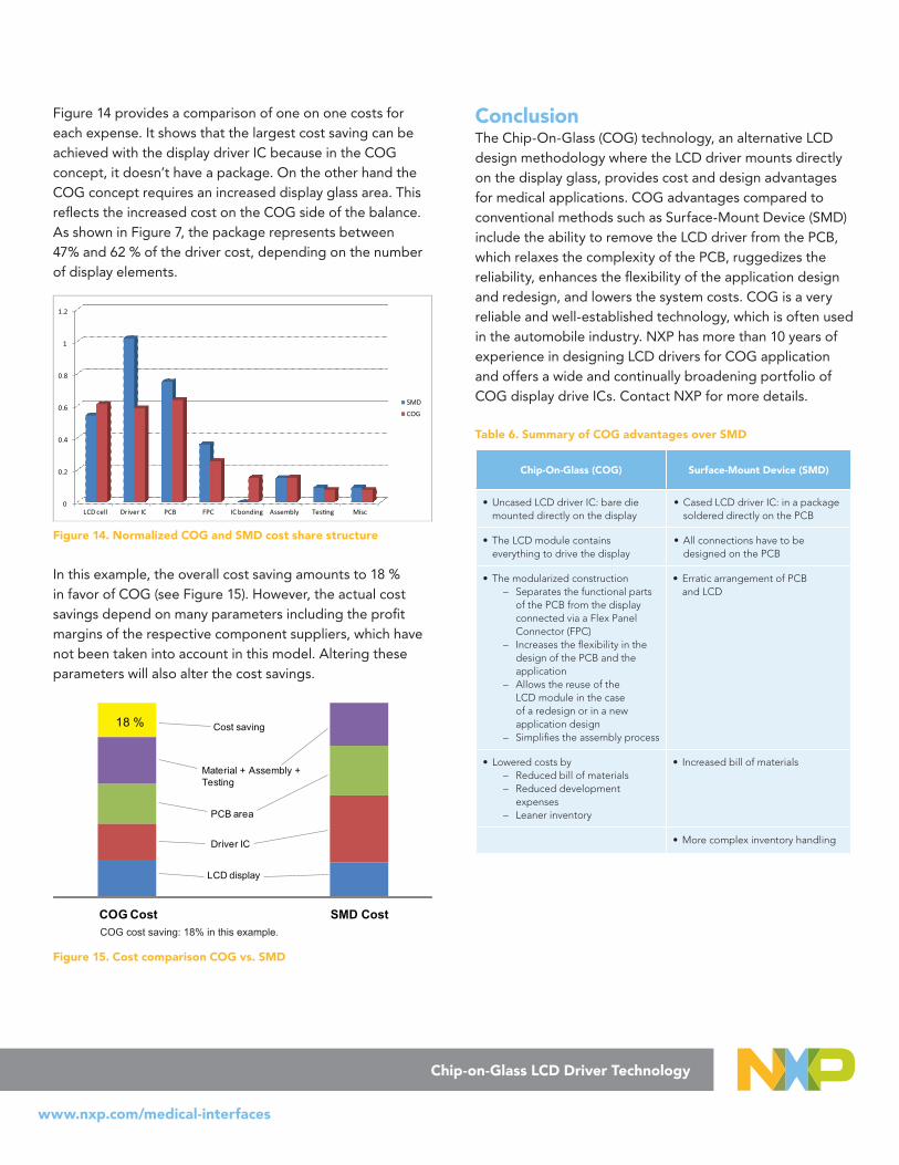
Figure 14 provides a comparison of one on one costs for each expense. It shows that the largest cost saving can be achieved with the display driver IC because in the COG concept, it doesn’t have a package. On the other hand the COG concept requires an increased display glass area. This reflects the increased cost on the COG side of the balance. As shown in Figure 7, the package represents between 47% and 62 % of the driver cost, depending on the number of display elements.
0
0.2
0.4
0.6
0.8
1
1.2
LCD cell Driver IC PCB FPC IC bonding Assembly Tes�ng Misc
SMD
COG
Figure 14. Normalized COG and SMD cost share structure
In this example, the overall cost saving amounts to 18 % in favor of COG (see Figure 15). However, the actual cost savings depend on many parameters including the profit margins of the respective component suppliers, which have not been taken into account in this model. Altering these parameters will also alter the cost savings.
18 %
COG Cost SMD Cost
Cost saving
Material + Assembly + Testing
PCB area
Driver IC
LCD display
Figure 15. Cost comparison COG vs. SMD
ConclusionThe Chip-On-Glass (COG) technology, an alternative LCD design methodology where the LCD driver mounts directly on the display glass, provides cost and design advantages for medical applications. COG advantages compared to conventional methods such as Surface-Mount Device (SMD) include the ability to remove the LCD driver from the PCB, which relaxes the complexity of the PCB, ruggedizes the reliability, enhances the flexibility of the application design and redesign, and lowers the system costs. COG is a very reliable and well-established technology, which is often used in the automobile industry. NXP has more than 10 years of experience in designing LCD drivers for COG application and offers a wide and continually broadening portfolio of COG display drive ICs. Contact NXP for more details.
Table 6. Summary of COG advantages over SMD
Chip-On-Glass (COG) Surface-Mount Device (SMD)
• Uncased LCD driver IC: bare die mounted directly on the display
• Cased LCD driver IC: in a package soldered directly on the PCB
• The LCD module contains everything to drive the display
• All connections have to be designed on the PCB
• The modularized construction – Separates the functional parts
of the PCB from the display connected via a Flex Panel Connector (FPC)
– Increases the flexibility in the design of the PCB and the application
– Allows the reuse of the LCD module in the case of a redesign or in a new application design
– Simplifies the assembly process
• Erratic arrangement of PCB and LCD
• Lowered costs by – Reduced bill of materials – Reduced development
expenses – Leaner inventory
• Increased bill of materials
• More complex inventory handling
COG cost saving: 18% in this example.
www.nxp.com/medical-interfaces
Chip-on-Glass LCD Driver Technology
References
[1] AN10170 — Design guidelines for COG modules with NXP monochrome LCD drivers
[2] AN10706 — Handling bare die
[3] AN10853 — ESD and EMC sensitivity of IC
[4] UM10204 — I2C-bus specification and user manual
Acronyms
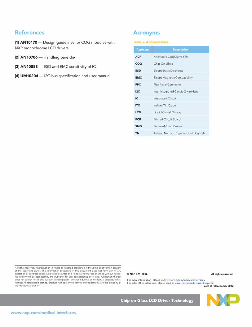
Table 7. Abbreviations
Acronym Description
ACF Anistropic Conductive Film
COG Chip-On-Glass
ESD ElectroStatic Discharge
EMC ElectroMagnetic Compatibility
FPC Flex Panel Connector
I2C Inter-Integrated Circuit (2 wire) bus
IC Integrated Circuit
ITO Indium Tin Oxide
LCD Liquid Crystal Display
PCB Printed-Circuit Board
SMD Surface-Mount Device
TN Twisted Nematic (Type of Liquid Crystal)
All rights reserved. Reproduction in whole or in part is prohibited without the prior written consent of the copyright owner. The information presented in this document does not form part of any quotation or contract, is believed to be accurate and reliable and may be changed without notice. No liability will be accepted by the publisher for any consequence of its use. Publication thereof does not convey nor imply any license under patent- or other industrial or intellectual property rights. Notice: All referenced brands, product names, service names and trademarks are the property of their respective owners.
© NXP B.V. 2012. All rights reserved. For more information, please visit: www.nxp.com/medical-interfaces. For sales office addresses, please send an email to: [email protected] Date of release: July 2012