Chip Multi-threading and Sun’s Niagara-serieskemper/cs654/slides/niagara.pdf · Chip...
27
Chip Multi-threading and Chip Multi-threading and Sun Sun ’ ’ s Niagara-series s Niagara-series Jinghe Jinghe Zhang Zhang Dept. of Computer Science Dept. of Computer Science College of William and Mary College of William and Mary
Transcript of Chip Multi-threading and Sun’s Niagara-serieskemper/cs654/slides/niagara.pdf · Chip...
Chip Multi-threading andChip Multi-threading andSunSun’’s Niagara-seriess Niagara-series
Jinghe Jinghe ZhangZhang
Dept. of Computer ScienceDept. of Computer Science
College of William and MaryCollege of William and Mary

OutlineOutline• Why CMT processors?• Sun’s Microprocessor• Conclusions

What is Chip Multi-What is Chip Multi-Threading?Threading?
• CMP: Chip that provide multiprocessing, called Multi-coreArchitecture. There are many cores per processor.
• HMT: Hardware Multithreading. There are many threads percore.
• CMT: Chip Multithreading has support to CMP Technologyand HMT Technology. There are many cores with multiplethreads per processor.
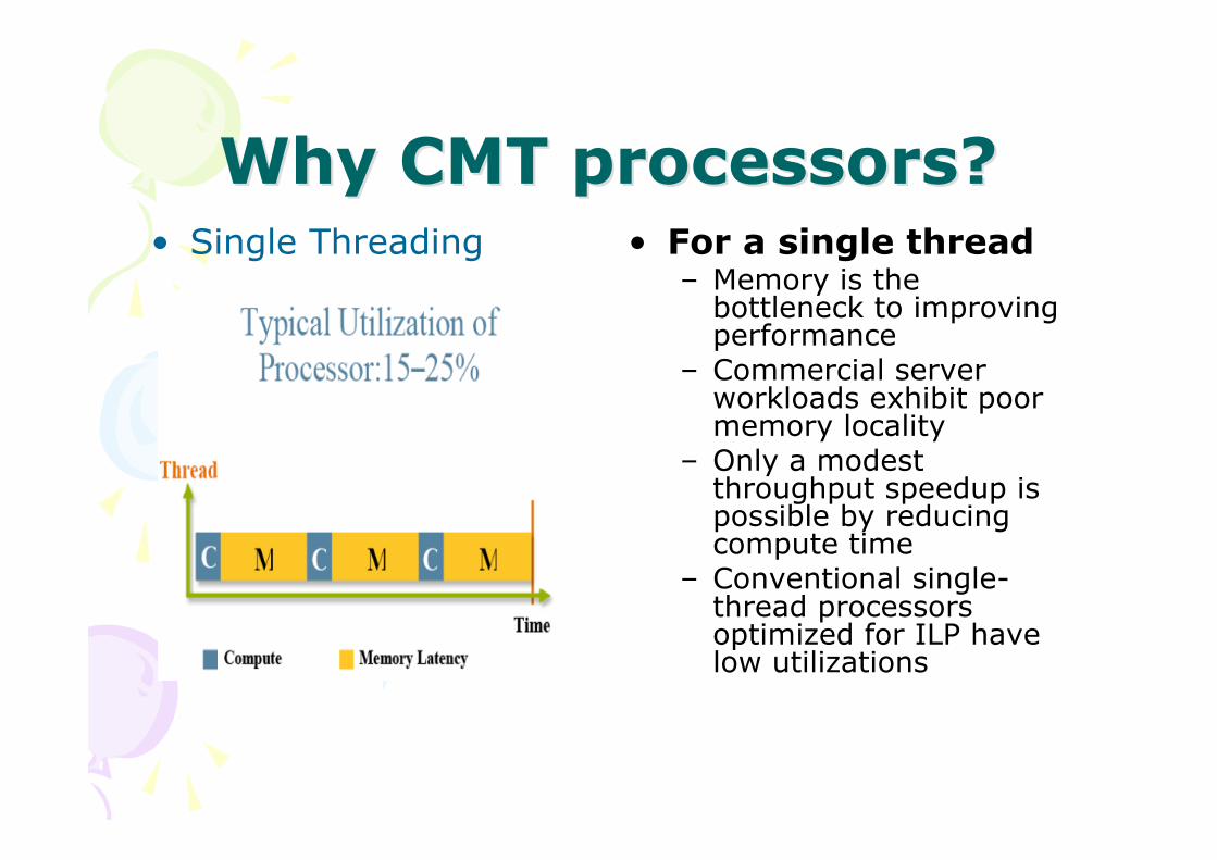
Why CMT processors?Why CMT processors?• Single Threading • For a single thread
– Memory is thebottleneck to improvingperformance
– Commercial serverworkloads exhibit poormemory locality
– Only a modestthroughput speedup ispossible by reducingcompute time
– Conventional single-thread processorsoptimized for ILP havelow utilizations
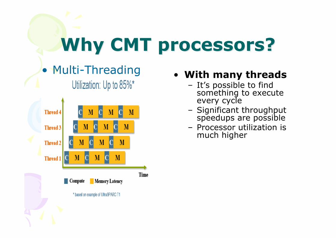
Why CMT processors?Why CMT processors?
• With many threads– It’s possible to find
something to executeevery cycle
– Significant throughputspeedups are possible
– Processor utilization ismuch higher
• Multi-Threading
Achievements and obstacles inAchievements and obstacles inimproving single threadimproving single thread
performanceperformance• Dramatic gains have been achieved in single-
threaded performance in recent years• Used a variety of micro-architectural techniques
– superscalar issue, out-of-order issue, on-chip caches &deeper pipelines
• Recent attempts to continue leveraging thesetechniques have not led to demonstrably betterperformance
• Power and memory latency considerationsintroduce increasingly insurmountable obstaclesto improving single thread performance– Several high frequency designs have been abandoned

Target: Commercial ServerTarget: Commercial ServerApplicationsApplications
• Server workloads are characterized by:– High thread-level parallelism (TLP)– Low instruction-level parallelism (ILP)
• Limited opportunity to boost single-threadperformance– Majority of CPI is a result of off-chip misses
• Couple high TLP in the application domainwith support for multiple threads ofexecution on a processor chip
• Chip Multi-threaded (CMT) processorscome to rescue!

Engineering SolutionEngineering Solution• Instead of optimizing each core, overall
goal was running as many concurrentthreads as possible maximizing andutilizing each core’s pipeline
• Each core is less complex than those ofcurrent high end processor, allowing 8cores to fit on the same die.
• Does not feature out-of-order execution,or a sizable amount of cache
• Each core is a barrel processor
SunSun’’s s MicroMicroprocessorsprocessors• Ultrasparc T line
–Ultrasparc T1 Niagara 2005 90nm–Ultrasparc T2 Niagara2 2007 65nm
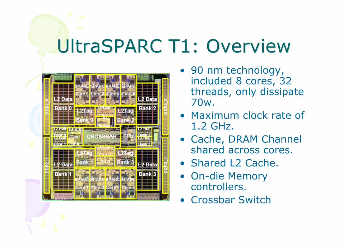
UltraSPARC T1: OverviewUltraSPARC T1: Overview• 90 nm technology,
included 8 cores, 32threads, only dissipate70w.
• Maximum clock rate of1.2 GHz.
• Cache, DRAM Channelshared across cores.
• Shared L2 Cache.• On-die Memory
controllers.• Crossbar Switch

T1T1’’s architectures architecture• 8 SPARC V9 CPU cores, with 4
threads per core, for a total of 32threads
• Fine-grained thread scheduling• One shared floating-point unit for
eight cores• 132 Gbytes/sec crossbar
interconnect for on-chipcommunication
• 16 KB of L1 I-cache, 8 KB of L1D-cache per CPU core
• 3 Mbytes of secondary (Level 2)cache – 4 way banked, 12 wayassociative shared by all CPUcores
• 4 DDR-II DRAM controllers – 144-bit interface per channel, 25GBytes/sec peak total bandwidth
Extra: Different types ofExtra: Different types ofMulti-threadingMulti-threading
• Coarse-grained multithreading, or switch-on-event multithreading, is when a thread has fulluse of the CPU resource until a long-latencyevent such as miss to DRAM occurs, in whichcase the CPU switches to another thread.
• Fine-grained multithreading is sometimes calledinterleaved multithreading; in it, thread selectiontypically happens at a cycle boundary.
• An approach that schedules instructions fromdifferent threads on different functional units atthe same time is called simultaneousmultithreading (SMT) or, alternately, horizontalmultithreading.

SPARC coreSPARC coreEach SPARC core has
hardware support for fourthreads. The four threadsshare the instruction, thedata caches, and the TLBs.
Each SPARC core has simple,in-order, single issue, sixstage pipeline. These sixstages are:
1. Fetch2. Thread Selection3. Decode4. Execute5. Memory6. Write Back

SPARC Core UnitsSPARC Core UnitsEach SPARC core has the following
units:• Instruction fetch unit (IFU)
includes the following pipelinestages – fetch, thread selection,and decode. The IFU also includesan instruction cache complex.
• Execution unit (EXU) includes theexecute stage of the pipeline.
• Load/store unit (LSU) includesmemory and writeback stages,and a data cache complex.
• Trap logic unit (TLU) includes traplogic and trap program counters.
• Stream processing unit (SPU) isused for modular arithmeticfunctions for crypto.
• Memory management unit(MMU).
• Floating-point frontend unit (FFU)interfaces to the FPU.

CPU-Cache CrossbarCPU-Cache CrossbarThe eight SPARC cores, the four L2-
cache banks, the I/O Bridge, andthe FPU all interface with thecrossbar.
The CPU cache crossbar (CCX)features include:
• Each requester queues up to twopackets per destination.
• Three stage pipeline – request,arbitrate, and transmit.
• Centralized arbitration with oldestrequester getting priority.
• Core-to-cache bus optimized foraddress plus double word
• store.• Cache-to-core bus optimized for
16-byte line fill. 32-byte Icacheline fill delivered in two back-to-back clocks.

Cache Coherence ProtocolCache Coherence Protocol• The L1 caches are write through, with allocate on load and no-
allocate on stores. L1 lines are either in valid or invalid states. TheL2 cache maintains a directory that shadows the L1 tags.
• A load that missed in an L1 cache (load miss) is delivered to thesource bank of the L2 cache w/ its replacement way from the L1cache. There, the load miss address is entered in thecorresponding L1 tag location of the directory, the L2 cache isaccessed to get the missing line and data is then returned to theL1 cache.– The directory maintains a sharers list at L1-line granularity.
• A store from a different or same L1 cache will look up thedirectory and queue up invalidates to the L1 caches that have theline. Stores do not update the local caches until they haveupdated the L2 cache. During this time, the store can pass data tothe same thread but not to other threads;– A store attains global visibility in the L2 cache.
• The crossbar establishes memory order between transactions fromthe same and different L2 banks, and guarantees delivery oftransactions to L1 caches in the same order.
• Direct memory access from I/O devices are ordered through theL2 cache.

What to expect next?
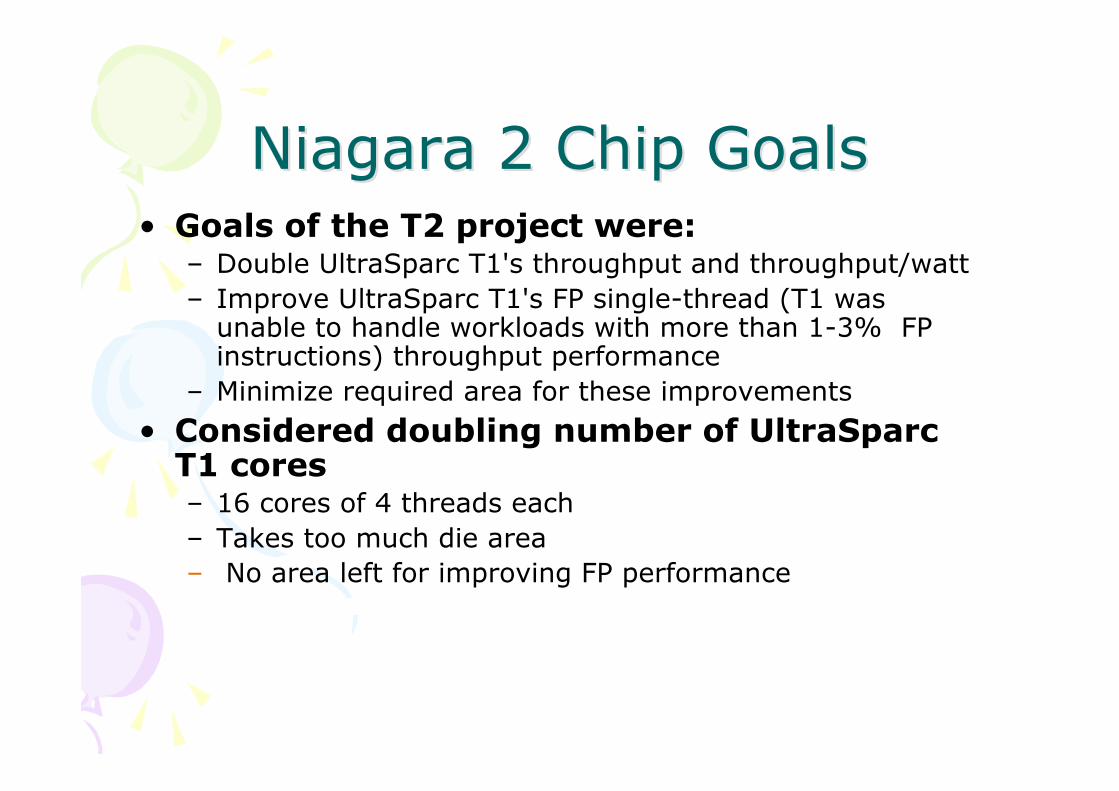
Niagara 2 Chip GoalsNiagara 2 Chip Goals• Goals of the T2 project were:
– Double UltraSparc T1's throughput and throughput/watt– Improve UltraSparc T1's FP single-thread (T1 was
unable to handle workloads with more than 1-3% FPinstructions) throughput performance
– Minimize required area for these improvements
• Considered doubling number of UltraSparcT1 cores– 16 cores of 4 threads each– Takes too much die area– No area left for improving FP performance

““Niagara 2 Opens theNiagara 2 Opens theFloodgatesFloodgates””
• 8 Sparc cores, 8 threadseach
• Shared 4MB L2, 8-banks,16-way associative
• Four dual-channel FBDIMMmemory controllers
• Two 10/1 Gb Ethernetports w/onboard packetclassification and filtering
• One PCI-E x8 1.0 port• 711 signal I/O, 1831 total
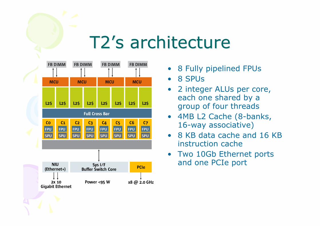
T2T2’’s architectures architecture• 8 Fully pipelined FPUs• 8 SPUs• 2 integer ALUs per core,
each one shared by agroup of four threads
• 4MB L2 Cache (8-banks,16-way associative)
• 8 KB data cache and 16 KBinstruction cache
• Two 10Gb Ethernet portsand one PCIe port
Efficient in-order singleEfficient in-order singleissue pipelineissue pipeline
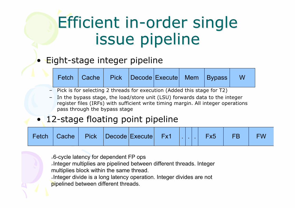
• Eight-stage integer pipeline
– Pick is for selecting 2 threads for execution (Added this stage for T2)– In the bypass stage, the load/store unit (LSU) forwards data to the integer
register files (IRFs) with sufficient write timing margin. All integer operationspass through the bypass stage
• 12-stage floating point pipeline
6-cycle latency for dependent FP opsInteger multiplies are pipelined between different threads. Integermultiplies block within the same thread.Integer divide is a long latency operation. Integer divides are notpipelined between different threads.
Fetch Cache Pick Decode Execute Mem Bypass W
Fetch Cache Pick Decode Execute Fx1 Fx5 FW. . . FB

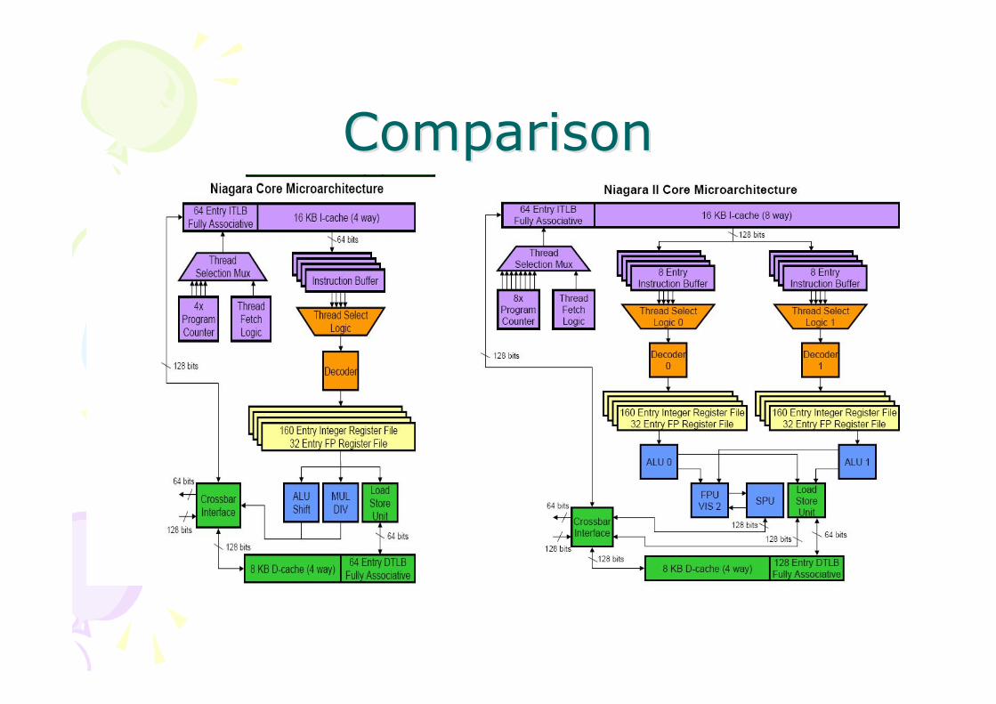
Core UnitsCore Units• EXU0/1 – Integer
Execution Units– 4 threads share each
unit– Executes one integer
instruction/cycle
• FGU –Floating/Graphics Unit
• The most visiblechanges: the dualexecution pipelinesand the new FGU
ComparisonComparison

Comparison: Main FeaturesComparison: Main Features
L3
UltraSPARC T1/T2Series
JBus (3.2 GB/s)JBus (3.2 GB/s)I/O-bus
4-channels, on-die, 400MT/s
4-channels, on-die, 400MT/sMemory controller
Full 8*9 crossbar switchBandwidth: >200 GB/sInterconnection NW
MonolithicMonolithicImpl. or the cores
SPARC V9SPARC V9Architecture
42.7 GB/s25.6 GB/sMemory bandwidth
4 MB/shared3 MB/sharedSize/allocationL2
4-way/core
63
On-die
1.2
279 mtrs.
379 mm2
90 nm
11/2005
Scalar integer FX cores
8 cores
UltraSPARC T1
8-way/coreMultithreading
72 (est.)TDP [W]
On-dieImplementation
1.4fc [GHz]
n.a.Nr. of transistors
342 mm2Die size
65 nmTechnology
2007Introduction
Dual-issue FX/FP coresCores
8 coresNr. of cores
UltraSPARC T2Models

ConclusionsConclusions• CMT designs support many HW threads via
efficient sharing of on-chip resources• CMT designs are rapidly evolving
– There will be more and more generations in the future
• CMT processors are a perfect match for thread-rich commercial applications
• Need to begin exploiting Speculative parallelismapproaches for applications with limited TLP
• Resource sharing and resultant inter-threadinteractions gives rise to many design challenges– Speculative prefetching, request prioritization, hot sets,
hot banks, BW limitations to name but a few...
ConclusionsConclusions• Niagara 1: a revolutionary 32-way multithreaded
processor with breakthrough performance levels,dramatically reduces power, cooling and spaceconsumption
• Niagara 2: based on Niagara 1, is the industry'sfirst "system on a chip," packing the most coresand threads of any general–purpose processoravailable, and integrating all the key functions ofa server on a single chip
CMT processors present an exciting range ofopportunities and challenges

• Questions?