CHIP & SEAL TECHNIQUES - Purdue University
27
CHIP & SEAL TECHNIQUES Chapter Five “Pavement Maintenance ” “Preventive Maintenance Treatments “ Participants Handbook ” by John P. Zaniewski &M i c h a e l S. M a Presented By: William F. Flora Information for this presentation is taken from the FHWA publication “Pavement Maintenance Effectiveness, Preventive Maintenance Treatment, Participants Handbook”. This publication includes information on preventive maintenance programs such as why to establish preventive maintenance, different preventive maintenance techniques and when to use them, and how to establish preventive maintenance. For information on obtaining the handbook, please contact the INDOT Pavement Management section at (317)233-1060 or the FHWA. Road School Proceedings - Page 104
Transcript of CHIP & SEAL TECHNIQUES - Purdue University
CHIP & SEAL TECHNIQUESChapter Five
“P a vem en t M a in ten a n ce ”“P reven tive M a in ten a n ce T rea tm en ts
“ Participants H a n d b o o k ” b y John P. Z an iew ski & M ic h a e l S. M a m lo u k
Presented By: William F. FloraInformation for this presentation is taken from the FHWA publication “P a ve m e n t M a in ten a n ce
E ffec tiven ess , P re v en tiv e M a in ten a n ce Treatm ent, P a r tic ip a n ts H a n d b o o k ”. This publication includes information on preventive maintenance programs such as why to establish preventive maintenance, different preventive maintenance techniques and when to use them, and how to establish preventive maintenance. For information on obtaining the handbook, please contact the INDOT Pavement Management section at (317)233-1060 or the FHWA.
Road School Proceedings - Page 104

CHAPTER 5. CHIP SEALS
INTRODUCTIONThe objective of this chapter is to present the proper techniques for chip seals (also called surface treatments, seal coat, or armor coating) with respect to material selection, design, and construction. Variations of chip seals are also described. These include modified binders, single, double and triple chip seals, precoated aggregates, sand seal, sandwich seal, and cape seal.
A chip seal is a sprayed application of asphalt binder immediately covered by a layer of one-sized aggregate. The chip seal course provides a new wearing surface. Chip seals provide several benefits, such as:
• Waterproofing the surface,
• Sealing small cracks,
• Protecting the original surface from solar radiation, and
• Improving the surface friction.
Chip sealing has been used for many years on low-volume roads.Recently, chip seals have been used by many States on roads with traffic volume greater than 5,000 vehicles/lane/day. However, in spite of its benefits, chip sealing has not been widely used for high-volume highways in the United States. Reasons limiting the use of chip seals on high- volume roads include:
Road School Proceedings - Page 105
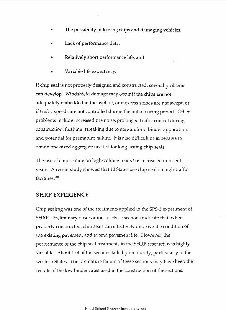
• The possibility of loosing chips and damaging vehicles,
• Lack of performance data,
• Relatively short performance life, and
• Variable life expectancy.
If chip seal is not properly designed and constructed, several problems can develop. Windshield damage may occur if the chips are not adequately embedded in the asphalt, or if excess stones are not swept, or if traffic speeds are not controlled during the initial curing period. Other problems include increased tire noise, prolonged traffic control during construction, flushing, streaking due to non-uniform binder application, and potential for premature failure. It is also difficult or expensive to obtain one-sized aggregate needed for long lasting chip seals.
The use of chip sealing on high-volume roads has increased in recent years. A recent study showed that 10 States use chip seal on high-traffic facilities.(26)
SHRP EXPERIENCEChip sealing was one of the treatments applied in the SPS-3 experiment of SHRP. Preliminary observations of these sections indicate that, when properly constructed, chip seals can effectively improve the condition of the existing pavement and extend pavement life. However, the performance of the chip seal treatments in the SHRP research was highly variable. About 1/4 of the sections failed prematurely, particularly in the western States. The premature failure of these sections may have been the results of the low binder rates used in the construction of the sections.
Road School Proceedings - Page 106
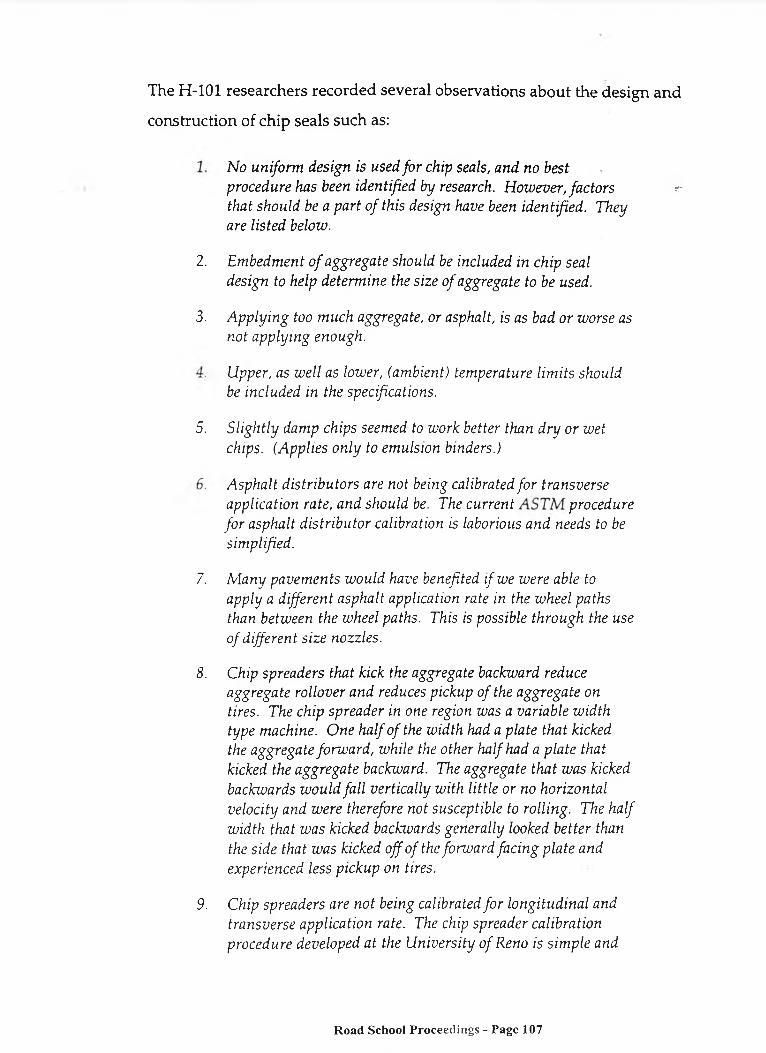
The H-101 researchers recorded several observations about the design and construction of chip seals such as:
1. N o u n ifo rm d es ig n is u sed fo r ch ip seals, a n d no b estp ro ced u re has been id en tified b y research. H o w e ve r , fa c to r s th a t sh o u ld be a p a r t o f th is design have been id en tified . T h eyare lis te d below .
2. E m b ed m en t o f a g g reg a te sh ou ld be in c lu ded in ch ip seal d es ig n to help d e te rm in e the s ize o f a gg rega te to be used.
3. A p p ly in g too m u ch a gg rega te , o r a sph alt, is as bad o r w o rse as n o t a p p ly in g enou gh .
4. U pp er, as w e ll as low er, (a m bien t) tem p era tu re l im its sh ou ld be in c lu d ed in the specifica tion s.
5. S lig h tly d am p ch ips seem ed to w ork b e tter than d r y o r w e t ch ips. (A p p lie s o n ly to em u lsion b in ders.)
6. A sp h a lt d is tr ib u to r s are n o t being ca libra ted fo r tra n sv e rse a p p lica tio n ra te , a n d sh o u ld be. The c u r r e n t p r o c e d u r e fo r a sp h a lt d is tr ib u to r ca libra tion is laborious a n d needs to be s im p lified .
7. M a n y p a v e m e n ts w o u ld h ave benefited i f w e w ere able to a p p ly a d ifferen t a sp h a lt app lica tion ra te in the w h eel p a th s than b etw een th e w h eel paths. This is poss ib le th ro u g h the use o f d ifferen t s iz e n o zz le s .
8. C h ip sp rea d ers th a t kick the a gg rega te backw ard reduce a g g reg a te ro llo ver a n d reduces p ick u p o f the a g g reg a te on tires. The ch ip sp rea d er in one region w as a varia b le w id th ty p e m achine. O n e h a lf o f the w id th had a p la te th a t kicked the a g g reg a te fo rw a rd , w h ile the o th er h a lf had a p la te th a t kicked the a g g reg a te backw ard. The a gg rega te th a t w a s kicked back w a rd s w o u ld fa ll v e r tic a lly w ith lit t le o r no h o r izo n ta l v e lo c ity a n d w e re therefore not su scep tib le to ro llin g . T he h a lf w id th th a t w a s k icked backw ards g en era lly looked b e tte r than the s id e th a t w a s k icked o ff o f the fo rw a rd fa c in g p la te a n d experien ced less p ick u p on tires. 9
9. C h ip sp rea d ers are n o t bein g ca libra ted fo r lo n g itu d in a l a n d tra n sv e rse a p p lica tio n rate. The chip sp read er ca libra tion p ro ced u re d eve lo p ed a t the U n iv e r s ity o f R eno is s im p le a n d
Road School Proceedings - Page 107
effective f o r both lo n g itu d in a l and tra n sv e rse ra tes. (C h ip sp rea d ers sh o u ld be ca libra ted both lo n g itu d in a lly a n d tra n sv e rse ly .)
10. M a n y d ifferen t ro llin g p a tte rn s , fro m on e p a ss o n ly , to f i v e o r se v en p asses , are used.
11. T he a m o u n t o f tim e after ro lling , b u t before o p e n in g the su rface to traffic seem ed im p o rta n t in h o t w ea th er.
12. R e q u ir in g redu ced speed fo r a t least one h ou r, e ith e r b y p o s tin g sp eed l im its or through the use o f p ilo t veh icles, seem ed to redu ce loss o f chips.
PAVEMENT CONDITION FOR SUCCESSFUL APPLICATIONSince chip seal does not add to the structural capability of pavement, the existing pavement has to be structurally sound in order to obtain a long performance life. If needed, the existing pavement has to be repaired, patched, and allowed to cure before applying the chip seal. The existing surface has to be clean.
Since chip seals follow the original profile of the pavement, they do not correct surface irregularities. Chip seals cannot be used on pavements with more than 10 to 15 mm of rutting. Aggregates in the ruts cannot be fully compacted, and cleaning loose aggregate from the rut with a power broom will dislodge the aggregates from the non-rutted area. If the surface has light-to-moderate bleeding, the binder application rate should be reduced. Pavements with high severity bleeding are not good candidates for chip seals.
Road School Proceedings - Page 108
DESIGN OF CHIP SEALSBinder SelectionThe binder used for chip seals is usually rapid setting emulsion, although medium setting emulsion could be used with fine aggregates. Asphalt cutback or asphalt cement can also be used. Asphalt emulsion is preferred over asphalt cement since it can be used with damp aggregates. Emulsion is also preferred over cutback because of environmental requirements and the slight saving in cost.
Aggregate SelectionThe aggregates used for chip seals should be one size of about 9.5 to 12.5 mm in order to provide good stability and maximum contact with tires. Cubical particle shape is preferred for the same reasons. Also, aggregates should have good resistance to abrasion, polishing, and degradation in order to resist traffic wear and impact and provide maximum friction resistance.
Table 12 presents the ASTM D1139 requirements for aggregates used for chip seals.
Application RateBefore construction, the chip seal has to be designed in order to find the target application rates for both asphalt binder and aggregates. Both mathematical and laboratory procedures are available for designing chip seals. Application rates are controlled to produce a pavement surface one stone thick with enough asphalt to hold the aggregate in place, but not so much that it will bleed. It is desirable to fill the voids between aggregate particles about two-thirds to three-fourths with asphalt. After rolling, an
Road School Proceedings - Page 109

Table 12. Specifications for aggregate used for chip seals.LA abrasion 40 percent maximum
Two crushed faces 60 percent minimumSodium sulfate soundness 12 percent maximum
Magnesium sulfate soundness 18 percent maximumClay lumps and friable particles 3 percent maximum
Flat or elongated pieces (for AASHTO sizes No. 5, 6 and 7)
10 percent maximum
embedment depth of aggregate into the asphalt film of 50 to 70 percent istypical.(21)
Table 13 shows typical application rates for aggregate and asphalt emulsion as a binder.(26)(27) Similar rates are recommended by ASTM D1369. Note that when the aggregate nominal size decreases, both aggregate and binder quantities decrease. The material quantities shown in table 13 should be adjusted based on local experience, road condition, specific gravity of aggregate, and aggregate precoating. The table also assumes an aggregate bulk specific gravity of 2.65. If the specific gravity is outside of the range of 2.55 and 2.75, the amounts of aggregate shown in the table should be multiplied by the ratio of actual bulk specific gravity to 2.65. In addition, the table shows ranges of aggregate gradation and rates of materials. If the aggregate has a gradation on the fine side of the specified range, a binder rate closer to the lower limit of the quantity range should be used. If the existing surface is flushed, the quantities shown in the table should be reduced by 0.04 to 0.27 liters/m. For absorbent surfaces the quantities should be increased by 0.14 to 0.40 liters/m2.
Road School Proceedings - Page 110

Table 13. Typical quantities of aggregate and emulsion forsingle chip seal applications.
Nominal Size of Aggregate
AASHTO Size No.
Quantity of Aggregate,
kg/m :Quantity of
Asphalt, liters/m2
Type and Grade of Asphalt
19 to 9.5 mm 6 22 to 27 1.6 to 2.0 Asphalt Cement1.8 to 2.3 RS-2, CRS-2
12.5 to 4.75 mm 7 14 to 16 0.9 to 1.4 Asphalt Cement1.4 to 2.0 RS-1, RS-2, CRS-1, CRS-2
9.5 to 2.36 mm 8 11 to 14 0.7 to 1.1 Asphalt Cement0.9 to 1.6 RS-l, RS-2, CRS-1, CRS-2
4.75 to 1.18 mm 9 8 to 11 0.5 to 0.7 RS-1, MS-1, CRS-1, HFMS-1
Sand AASHTOM-6
5 to 8 0.5 to 0.7 RS-1, CRS-1, MS-1, HFMS-1
The values in table 13 are general estimates of the quantity of materials required. A rather simple laboratory procedure can directly estimate the required amount of aggregate and asphalt. The aggregate is spread over an area of 1 m2.(:i) A 1 m x 1 m x 25 mm pan can be used for this purpose. Aggregate is placed in the densest condition anticipated to exist in the field. The weight of the aggregate needed to cover the pan with a single layer of aggregates equals the required weight of the aggregate to be used in the field in kg/m2. The pan is then carefully filled with water until the surface of the water comes just to the top of the aggregate. The volume of water is determined and approximately two-thirds of that volume is the quantity of asphalt residue required in the field.
Road School Proceedings - Page 111

CONSTRUCTION CONSIDERATIONSPavement PreparationBefore applying the chip seal, the condition of the existing pavement has to be surveyed. Most old pavements need some patching and removal of excess asphalt before chip sealing. Damaged areas must be patched and wide cracks sealed. The chip seal should not be placed until all of the asphalt used in the repair of the section has thoroughly cured. Immediately prior to construction of the chip seal, the pavement must be cleaned with a power broom.
Weather Conditions
Many specifications require the air temperature be at least 10 C before chip sealing begins. Some require the road surface temperature to beabove 20 C before work starts. ‘ Air temperatures of 40° C or higher may reduce the bonding of the aggregates due to rapid breaking of the emulsion. Chip sealing should never be started when the surface is wet or when it is threatening to rain.
Construction Process MethodologyThe construction sequence for a chip seal is:
• Clean surface with a power broom.
• Apply binder with a calibrated distributor truck.
• Apply cover aggregate when the binder is tacky.
• Roll the aggregate to embed in the binder.
Road School Proceedings - Page 112
Allow binder to set.
• Clean excess aggregate with a power broom.
Equipment consists of trucks, asphalt distributor, chip spreader, pneumatic (rubber tired) rollers, steel-wheel rollers, and power brooms. Sufficient trucks must be available in order to ensure continuous operation. There must be enough rollers to immediately roll the aggregates behind the spreader without delaying the operation.
The asphalt distributor consists of an insulated tank, asphalt pump, spray bar and nozzles, bitumeter wheel, and controls as illustrated in figure 17.<21> Most distributors are equipped with a heating system that will maintain the asphalt at the proper spray temperature. The asphalt distributor is equipped with a control system which includes a valve system which governs the flow of material, a pump tachometer or a pressure gauge that registers the pump output, and a bitumeter. The bitumeter is a rubber-tired wheel mounted on a retractable frame with a cable leading to a dial in the cab of the vehicle. The dial registers the rate of travel in distance per minute and the traveled distance. The bitumeter should be kept clean and checked for accuracy at regular intervals. The typical capacity of the truck varies from 3,000 to 20,000 liters. The spray bar can cover a width of 3 to 9 m in a single pass, depending on the pump capacity.
Figure 18 shows the asphalt distributor, chip spreader and pneumatic rollers prior to start of the chip sealing job. Figures 19 and 20 show the chip spreader and the rollers, respectively.
Road School Proceedings - Page 113

Figure 17. A schematic of asphalt distributor components.
Figure 18. Asphalt distributor, chip spreader and rollers.
Road School Proceedings - Page 114

Figure 19. Spreading chips with a chip spreader.
Figure 20. Compacting chip seals using rubber wheel rollers.
Road School Proceedings - Page 115
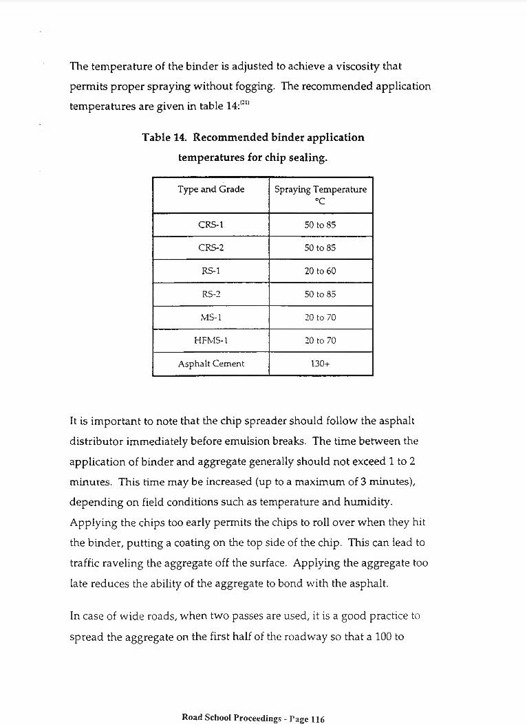
The temperature of the binder is adjusted to achieve a viscosity that permits proper spraying without fogging. The recommended application temperatures are given in table 14:<21)
Table 14. Recommended binder application temperatures for chip sealing.
Type and Grade Spraying Temperature°C
CRS-l 50 to 85CRS-2 50 to 85RS-1 20 to 60RS-2 50 to 85
MS-1 20 to 70HFMS-1 20 to 70
Asphalt Cement 130+
It is important to note that the chip spreader should follow the asphalt distributor immediately before emulsion breaks. The time between the application of binder and aggregate generally should not exceed 1 to 2 minutes. This time may be increased (up to a maximum of 3 minutes), depending on field conditions such as temperature and humidity. Applying the chips too early permits the chips to roll over when they hit the binder, putting a coating on the top side of the chip. This can lead to traffic raveling the aggregate off the surface. Applying the aggregate too late reduces the ability of the aggregate to bond with the asphalt.
In case of wide roads, when two passes are used, it is a good practice to spread the aggregate on the first half of the roadway so that a 100 to
Road School Proceedings - Page 116
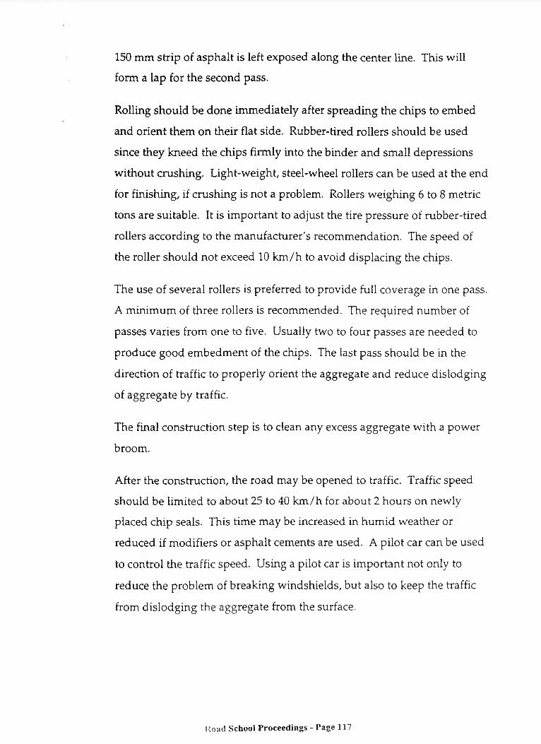
150 mm strip of asphalt is left exposed along the center line. This will form a lap for the second pass.
Rolling should be done immediately after spreading the chips to embed and orient them on their flat side. Rubber-tired rollers should be used since they kneed the chips firmly into the binder and small depressions without crushing. Light-weight, steel-wheel rollers can be used at the end for finishing, if crushing is not a problem. Rollers weighing 6 to 8 metric tons are suitable. It is important to adjust the tire pressure of rubber-tired rollers according to the manufacturer's recommendation. The speed of the roller should not exceed 10 km/h to avoid displacing the chips.
The use of several rollers is preferred to provide full coverage in one pass. A minimum of three rollers is recommended. The required number of passes varies from one to five. Usually two to four passes are needed to produce good embedment of the chips. The last pass should be in the direction of traffic to properly orient the aggregate and reduce dislodging of aggregate by traffic.
The final construction step is to clean any excess aggregate with a power broom.
After the construction, the road may be opened to traffic. Traffic speed should be limited to about 25 to 40 km/h for about 2 hours on newly placed chip seals. This time may be increased in humid weather or reduced if modifiers or asphalt cements are used. A pilot car can be used to control the traffic speed. Using a pilot car is important not only to reduce the problem of breaking windshields, but also to keep the traffic from dislodging the aggregate from the surface.
Road School Proceedings - Page 117

Inspection and AcceptanceBefore work begins, equipment should be checked to make sure it is in good working condition and properly calibrated. Be certain that nozzles are clear and at the correct angle, the spray bar is at the correct height, and the pump is set at proper pressure. Verify the calibration of the spray bar.
All nozzles have to be clean and unplugged. Otherwise a non-uniform application of binder or uncovered longitudinal streaks will develop. Nozzles have to be set at an angle so that the spray fans do not interfere with each other. The nozzle angle varies according to the make of the distributor but is typically between 15 and 30 degrees as shown on figure 21. It is important that all nozzles be set at the proper angle within close tolerances in order to obtain a uniform application rate.
The height of the spray bar must be properly set and maintained to obtain a uniform spray and avoid longitudinal streaking. Improper spray bar height causes streaks of over and under binder application. The height of the spray bar should be adjusted to produce a single, double, or triple coverage in order to obtain a uniform binder distribution as shown in figure 22. During construction, it may be necessary to adjust the spray bar height to compensate for a change in the truck height as the emulsion load on the truck is reduced. A double coverage is more suitable for a 100 mm nozzle spacing, but triple coverage can also be used. Note that triple coverage requires a greater height between the spray bar and the pavement surface. This may permit wind distortion of the spray fans.
Adjusting the height of the spray bar is done manually. The height to produce a single coverage is determined first by visual observation. To obtain a double coverage, every other nozzle is turned off and the spray bar is raised in increments of 10 mm until a single coverage is obtained.
Road School Proceedings - Page 118
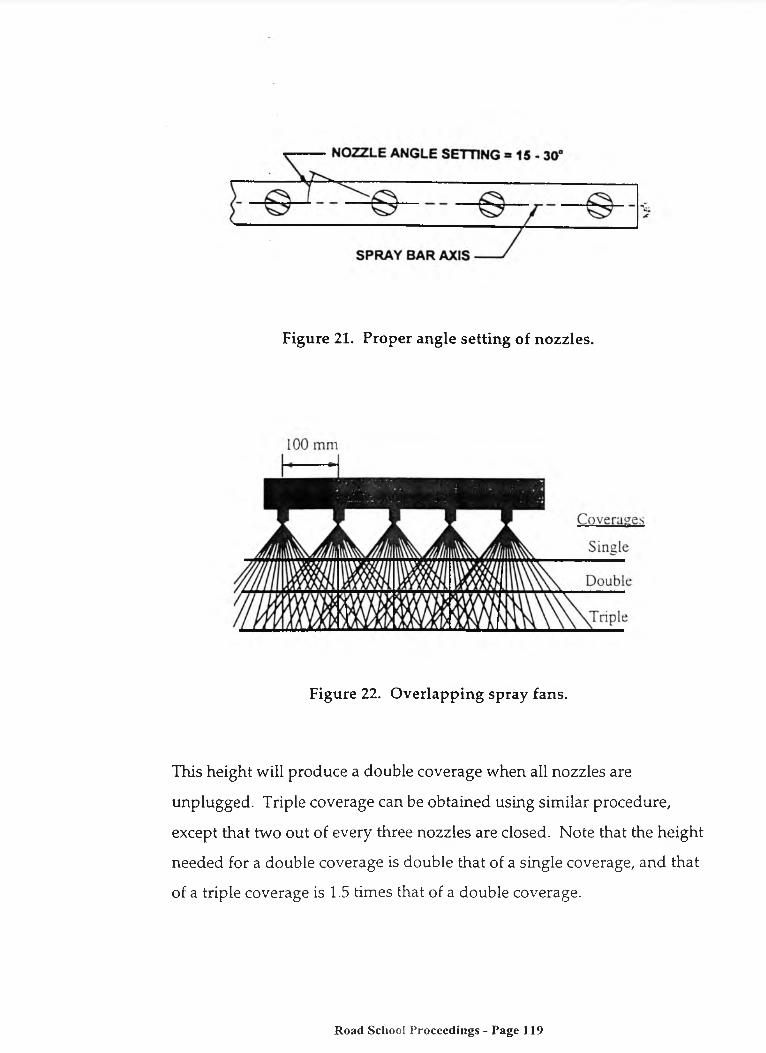
Figure 21. Proper angle setting of nozzles.
Figure 22. Overlapping spray fans.
This height will produce a double coverage when all nozzles are unplugged. Triple coverage can be obtained using similar procedure, except that two out of every three nozzles are closed. Note that the height needed for a double coverage is double that of a single coverage, and that of a triple coverage is 1.5 times that of a double coverage.
Road School Proceedings - Page 119

The application rate of the spray bar should be verified prior to use. Calibration is performed using pre-weighed metal trays or sheets of heavy paper to determine the amount of binder per unit area. To ensure uniform binder application, this process is repeated in both longitudinal and transverse directions. During construction, the application rate can be monitored by measuring the amount of emulsion used over a fixed-length section of pavement.
The asphalt distributor should be driven at the appropriate speed.Asphalt should be at the proper temperature before spraying. The asphalt binder should not be too hot or too cold. A typical range of binder temperature between 55 and 80° C is common when rapid setting emulsions are used. If asphalt cement is used, it is normally sprayed at temperatures of 130° C or higher. Air temperatures of 40° C or higher may reduce the bonding of the aggregates due to rapid setting of the emulsion. Overheating could break the emulsion prematurely, which reduces the bond with aggregate.
The aggregate spreader should be checked to ensure proper working condition. The aggregate spread rate should be adjusted to form a single layer. The rate of chip spreading and the consistency of spreading in both transverse and longitudinal directions should be checked prior to each application. Chip spreaders can be calibrated by placing mats of known surface area (approximately 1 mz) in the path of the spreader. Chip quantities on each mat are weighed. Spreader gates are adjusted to the desired quantity of chips. Calibration should be performed using the same aggregate as that used in the chip sealing. Chip spreaders that kick the aggregate backward or drop the aggregate straight down reduce aggregate rollover.
Road School Proceedings - Page 120

Aggregate should be spread immediately after spraying asphalt to embed and orient them on their flat side. Longitudinal joints can be eliminated by using full-width applications. Also, rough and unsightly transverse joints can be avoided by starting and stopping the asphalt and aggregate spread on building paper.
Rolling should be done using pneumatic-tired rollers immediately after the aggregate is spread and continue until the aggregate is properly seated in the asphalt membrane. Rollers should be as close as possible to the chip spreader.
Loose aggregate should be swept by lightly brooming with a power broom (figure 23) after the asphalt has set and a good bond has developed. The time required before brooming varies and ranges from 1 day to a few weeks. In any case, a good bond between the binder and the chips is a prerequisite. Brooming should be performed during the cooler morning weather. If the embedment is low and there are signs of chip loss after brooming, a fog seal can be considered.
SpecificationsState specifications usually include description of work, materials, construction details, weather limitations, method of measurement, and basis of payment. For example, New York requires that asphalt and aggregate need to meet State specification requirements. Crushed stone, crushed gravel, or crushed slag can be used. Aggregate shall not contain more than 5 percent chert. Aggregate sizes for single and double chip seals are specified. The bituminous material should not be applied on a wet surface when the air temperature is below 10° C or above 35°C, or when weather conditions would prevent the proper construction of the surface treatment. The required equipment is a bituminous material
Road School Proceedings - Page 121

distributor, an aggregate spreader, a pneumatic rubber tire roller, and a power broom. The pavement surface needs to be free from irregularities to provide a reasonably smooth and uniform surface to receive the treatment. The bituminous material should be applied at a rate of 1.1 to 1.8 liters/m2 unless otherwise directed by the engineer. Aggregate is to be spread immediately following the application of asphalt at a rate of 8 to 14 kg/m 2 unless otherwise directed by the engineer. Traffic should be detoured until the final layer is applied and rolled, after which controlled traffic may be permitted. Traffic shall be maintained at a speed not to exceed 25 km/h for 2 to 4 hours after rolling. The time and the method of traffic control are determined by the engineer.
Figure 23. Brooming excess chips using a rotary broom.
Road School Proceedings - Page 122

PERFORMANCEChip seals typically provide good performance on highways with as much as 5,000 vpd for 4 to 7 years.(23) Several chip seal projects were constructed under the SHRP SPS-3 project. Preliminary indications show that timing of chip seal applications relative to existing pavement condition is critical to its performance and cost-effectiveness.By and large, chip seals in Europe and other countries are similar to those in the United States However, polymer modified binders are commonly used in Europe. In other countries such as Australia, New Zealand, and South Africa, large stone aggregate is used to obtain long service life.(23)
LIMITATIONSSome of the limitations of chip seal applications include the difficulty and expense of obtaining one-sized aggregates needed for long lasting chip sealing. Also, windshield damage may occur if aggregates larger than 12.5 mm are used, especially if the chips are not adequately embedded in the asphalt or excessive stones are not swept. Other problems include increased tire noise, prolonged traffic control, flushed pavements, and potential for premature failure if not properly designed or constructed.
VARIATIONS ON CHIP SEALSSeveral variations can be used with the chip seal to address some of the previously noted problems. These variations include using modified binders; single, double, or triple chip seal; asphalt cement; precoated chips; sand seal; sandwich seal; and cape seal.
Road School Proceedings - Page 123
Alternative BindersSome States such as Arizona, California, Texas, and Washington use polymer-modified chip seal on their high-volume roads. The use of modified emulsion reduces temperature susceptibility, provides better adhesion to the existing surface, and allows the road to be opened to traffic earlier. Both recycled rubber and synthetic polymers have been used as modifiers. The cost of crumb rubber modified (CRM) chip seals has been about twice the cost of conventional seals. Wet processed asphalt-rubber has a higher viscosity than asphalt cement at higher temperatures. This permits increasing the binder application rate, and better chip retention, without resulting in a bleeding problem.
Asphalt cement is sometimes used as a binder to allow opening the roadway traffic earlier. However, it increases the cost and is more sensitive to dirty aggregates than emulsion binders. When asphalt cement is used, the chips must be placed and rolled while the asphalt cement is hot enough to allow embedment of the aggregates. Depending on ambient conditions, this can be limited to just a few minutes of effective rolling time.
Double and Triple Chip SealsA double or triple chip seal consists of two or three alternate applications of asphalt and aggregate, respectively. The nominal top size of the cover aggregate for each successive course should not be more than one-half that of the preceding one. When using multiple chip seal applications, the first layer should be cured before the application of the second layer.
The aggregate size of the first course determines the surface layer thickness, while the aggregate in the following layers fills voids in the preceding layers. The use of multiple chip seals fill the voids between
Road School Proceedings - Page 124

aggregate particles and increase the service life. The use of double and triple chip seals is not as common as single chip seals. Double chip seals can cost about 1 1/2 times single chip seals; however, double chip seals usually give more than twice the service life of single chip seals.
The New York specifications for double surface treatment require the application rates given in table 15.
Table 15. New York DOT application rates for double chip seal.Bituminous Material,
liters /m :Aggregate,
kg/m 21st Course (base) 1.1 to 2.3 11 to 16
2nd Course (surface) 1.1 to 1.8 8 to 14
Precoated ChipsPrecoated aggregate is used by a small number of States such as Illinois, Oregon, Pennsylvania, Texas, Utah, and Virginia for high-volume roads. Precoating eliminates dust and improves adhesion between aggregate and binder. Asphalt cement is used for coating with a content of about 0.75 to 1 percent by weight of chips. A 90 percent or more coating is desired. A mixing temperature of about 140 C is recommended. Correctly coated aggregate particles should separate from each other easily and flow readily through spreaders.
The use of precoated chips is not as common as the use of uncoated chips due to the difficulty in coating and spreading the chips and the extra expense. Also, it is reported that coated aggregates delay the break of the cationic emulsions.
R o a d School Proceedings - Page 1 2 5
Sand SealSand seal is an application of asphalt followed by a sand cover aggregate. The sand or stone screenings should be 6.35 mm sieve size or smaller. The binder used for sand seals is usually a rapid setting (anionic or cationic) or a medium setting (anionic or high float) emulsion. Therefore, sand seal is essentially the same as chip seal except finer aggregates are used as cover.
Sand seals are used to:
• Improve microtexture and provide better surface friction,• Renew old asphalt surfaces,• Seal small cracks and surface voids,• Address raveling of chip seals and open-graded surfaces in high-
volume roads, and• Maintain and delineate shoulders in high-volume roads.
Sand seals are not routinely used by many agencies. They have mostly been applied to low-volume roads. Some agencies have applied sand seals on moderate-to-high-volume roads and reported good performance. The use of sand seals on high-volume roads is limited due to the excessive traffic control requirements and the difficulty in determining the appropriate binder rate.The rate of emulsion application varies from 0.5 to 0.7 liters/ m2 depending on the texture of the existing surface, local conditions, and traffic. Sand is applied at a rate of about 5 to 8 kg/m:.
Sand seal should not be applied unless the surface temperature is at leasto15 C. Pneumatic tire rollers are recommended. Two hours of lane closure
is generally required under normal conditions. The performance life
Road School Proceedings - Page 126

varies between 3 and 6 years. Variables include traffic, construction quality, materials, and environmental conditions.
Among the limitations of sand seals is that it is not effective for long-term crack sealing, it may take several hours for the emulsion to cure and may not provide the distinct delineation depending on the aggregate color.
Sandwich SealSandwich seal is an application of binder sandwiched between two layers of aggregate. In this process, one-sized aggregates (either 4.75 or 9.5 mm) are spread on a clean and dry pavement at a rate of about 80 percent of the amount needed to provide coverage at one stone thickness. Aggregates are compacted and asphalt emulsion is applied at a rate of 1.2 to 1.5 times the amount for a conventional single chip seal. A second course of one-sized 2.36 to 4.75 mm is applied and rolled.123’
Before applying the sandwich seal the existing pavement has to be clean and dry. All aggregates used in the sandwich seal application have to be clean. A light-weight steel roller may be used to seat the first layer of aggregate. A slow-moving pneumatic roller is used to compact the top aggregate layer.
Sandwich seal is used for sealing high traffic pavements and flushed pavements. It also improves skid resistance. Sandwich seal has approximately the same service life as the double chip seal.
Sandwich seal is generally more economical than the double chip seal since only one application of binder is used.
Road School Proceedings - Page 127

A cape seal is chip seal topped with a seal coat such as slurry seal. The name is derived from the Cape Province of South Africa where it was o riginally developed. The cape seal provides a dense surface with good skid resistance and a relatively long service life. The slurry cover over the chip seal eliminates the problem with loose aggregates and reduces traffic noise. These properties of cape seal make it very suitable for high-traffic- volume roads.
In this treatment, a single course of chip seal is applied in the conventional manner. The chip seal cures for 4 to 10 days; the slurry seal is then applied. The surface has to be broomed before applying the slurry in order to provide better adhesion of the slurry. After the chip seal has been cured, the slurry seal is applied to fill the texture of the chip seal.
For a 15 mm thick layer, the emulsion is applied at a rate of about 1.4 to2 2 2.0 1/m , the chip at a rate of 14 to 16 kg/m , and the slurry mixture
(usually type I) at a rate of 3 to 5.5 kg/m .
After applying the slurry seal, traffic should be detoured for about 2 hours in warm weather and 6 to 12 hours or more in cool weather. One of the limitations of the cape seal is the need to establish traffic control twice in a relatively short time period.
Cape Seal
Road School Proceedings - Page 128

Road School Proceedings - Page 129

ME
TR
IC (
SI*
) C
ON
VE
RS
ION
FA
CT
OR
S
Road School Proceedings - Page 130