CHINA INDIA INDONESIA THAILAND MALAYSIA HONG KONG … · Casting Technology New Zealand Inc. PO Box...
24
ASIA PACIFIC Vol 58, No 2 June 2012 CASTING TECHNOLOGIES Print Post Approved 255003/01135 CHINA • INDIA • TAIWAN • SINGAPORE INDONESIA • THAILAND • PHILIPPINES MALAYSIA • HONG KONG • JAPAN • EUROPE USA • AUSTRALIA • KOREA • NEW ZEALAND
-
Upload
trinhkhanh -
Category
Documents
-
view
218 -
download
0
Transcript of CHINA INDIA INDONESIA THAILAND MALAYSIA HONG KONG … · Casting Technology New Zealand Inc. PO Box...
A S I A P A C I F I CVol 58, No 2 June 2012
CASTING TECHNOLOGIES
Prin
t Pos
t App
rove
d 25
5003
/0113
5
CHINA • INDIA • TAIWAN • SINGAPORE INDONESIA • THAILAND • PHILIPPINES
MALAYSIA • HONG KONG • JAPAN • EUROPE USA • AUSTRALIA • KOREA • NEW ZEALAND

Reclaimed Sand Temperature
PLC & Touch-screen
Supply Tanks
Fast Catalyst Pump
Slow Catalyst Pump
Resin Pump
New Sand Temperature
Casting process simulation is geared toward the reduction of energy consumption, raw material use and the environmental impact of your foundry. Increasing demands require even more fl exibility and faster decisions on your part. Meeting these challenges depends on technically and economically sound solutions.
Optimized Reality – this is where simulation with MAGMA shows its strength.
SHAPE THE FUTURE !
Contact in Asia:MAGMA Engineering Asia Pacifi c Pte Ltd 25 International Business Park, #03-76/79 German Centre Singapore 609916 Phone: +65 6564 3435 Fax: +65 6564 0665 [email protected] www.magmasoft.com.sg
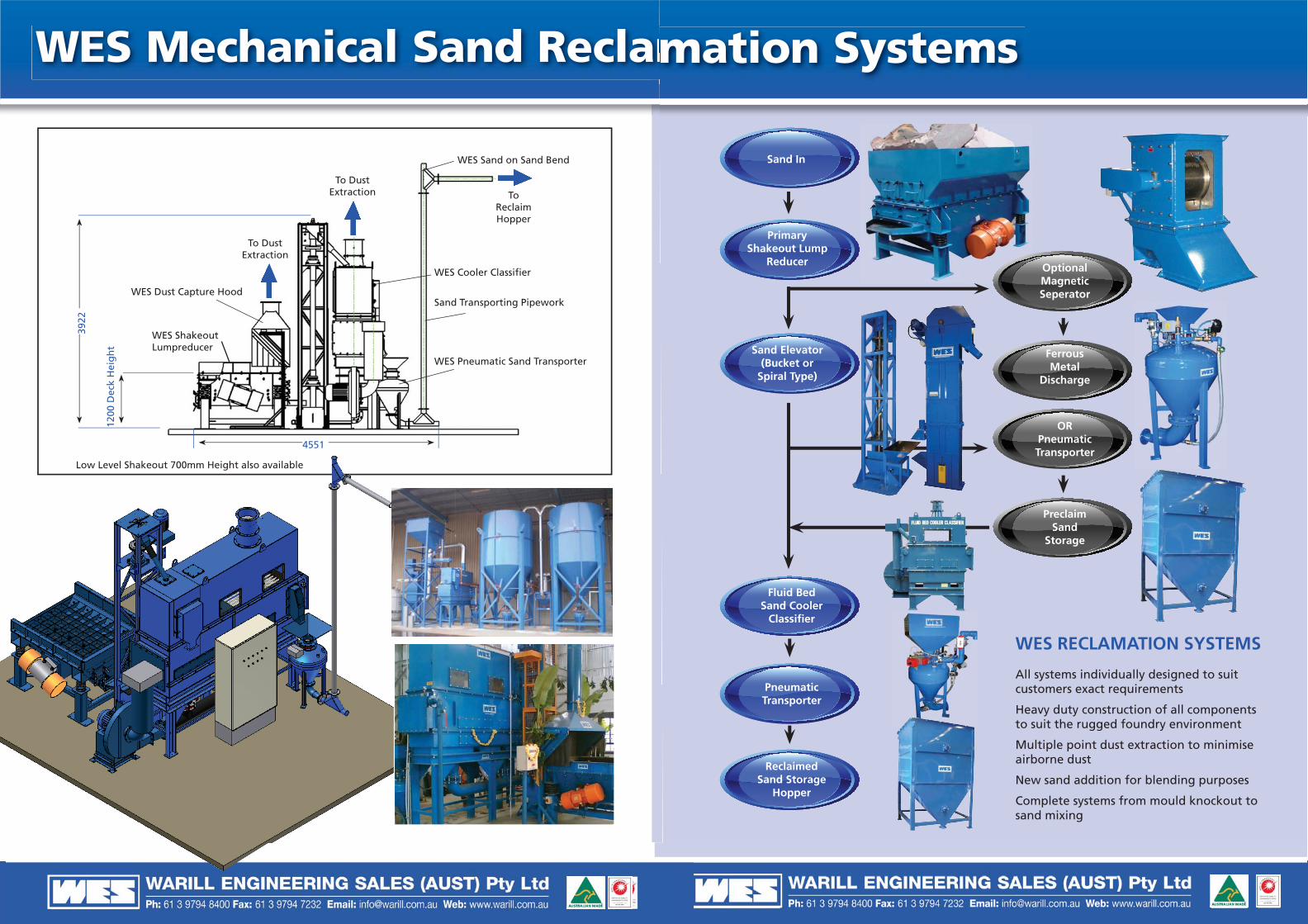
Sand In
Ferrous Metal
Discharge
OR Pneumatic Transporter
Preclaim Sand
Storage
Sand Elevator (Bucket or
Spiral Type)
Primary Shakeout Lump
Reducer
Fluid Bed Sand Cooler
Classifi er
Pneumatic Transporter
Reclaimed Sand Storage
Hopper
WES RECLAMATION SYSTEMS
All systems individually designed to suit customers exact requirements
Heavy duty construction of all components to suit the rugged foundry environment
Multiple point dust extraction to minimise airborne dust
New sand addition for blending purposes
Complete systems from mould knockout to sand mixing
Optional Magnetic Seperator
amation Systems
WES Sand on Sand Bend
To Reclaim Hopper
WES Cooler Classifi er
Sand Transporting Pipework
WES Pneumatic Sand Transporter
WES ShakeoutLumpreducer
WES Dust Capture Hood
To Dust Extraction
To Dust Extraction
3922
4551
1200
Dec
k H
eig
ht
Low Level Shakeout 700mm Height also available
WES Mechanical Sand Reclam

2 www.metals.rala.com.au
Jimmy Loke Yoon CheeDirector, Yoonsteel Foundry MalaysiaRepresentative of FOMFEIAMr Gopal RamaswamiNational Secretary of the Institute of Indian Foundrymen, IndiaEmail: [email protected] FrostWorld Consulting Specialist Foundry Process [email protected]
Mr Zhang LiboExecutive Vice PresidentChina Foundry [email protected] Seksan TangkoblabPresident Thai Foundrymen’s SocietyDr John PearceMetals SpecialistMTEC National Metals and MaterialsTechnology Centre, Thailand
Industry AssociationsAustralian Foundry InstituteSouth Australia: The Secretary, PO Box 288, North Adelaide SA 5006Western Australia: The Secretary,[email protected] South Wales: The Secretary, Locked Bag 30, Bankstown NSW 2200,[email protected]: C/- PO Box 89, Acacia Ridge QLD 4110Victoria: PO Box 4284, Dandenong South VIC 3164Casting Technology New Zealand Inc.PO Box 1925, Wellington, New ZealandTel: +64 4 496 6555, Fax: +64 4 496 6550China Foundry Association3rd Floor, A-32 Zizhuyuan RdHaidian District, Beijing 100048, CHINATel: +86 10 6841 8899 Fax: +86 10 6845 8356Web: www.foundry-china.comFederation of Malaysia Foundry & Engineering Industries Association(FOMFEIA), 8 Jalan 1/77B, Off Jalan Changi at Thambi Dollah 55100,Kuala Lumpur, MalaysiaTel: +603 241 8843, Fax: +603 242 1384Institute of Indian FoundrymenIIF Center, 335 Rajdanga Main Road, East Kolkata Township P.O.Kolkata - 700107 IndiaTel: +91 33 2442 4489, +91 33 2442 6825Fax: +91 33 2442 4491
Japanese Association of Casting TechnologyNoboru Hatano, Technical Director, JACT,Nakamura Bldg, 9-13, 5-chome, Ginza,Chuo-ku, Tokyo, 104 JapanTel: +81 3 3572 6824, Fax: +81 3 3575 4818Metalworking Industries Association of the Philippines Inc.Pacificador Directo, National President, MIAP, No. 55 Kanlaon St, Mandaluyong,1501 Metro Manila, PhilippinesTel: +632 775 391, Fax: +632 700 413Philippine Iron & Steel Institute(PISI), Room 518, 5th Floor, Ortigas Building,Ortigas Avenue, Pasig, Metro ManilaTel: +632 631 3065, Fax: +632 631 5781Philippine Metalcasting Association Inc.(PMAI), 1135 EDSA, Balintawak, Quezon City Metro Manila, PhilippinesTel: +632 352 287, Fax: +632 351 7590South East Asian Iron & Steel Institute2E 5th Floor Block 2, Worldwide Business ParkJalan Tinju 13/50, 40675 Shah Alam, Selangor MalaysiaTel: +603 5519 1102, Fax: +603 5519 1159, Email: [email protected] Foundry AssociationKhun Wiboolyos AmatyakulPresident Thai Foundry Association86/6 1st Floor BSID BuildingBureau of Supporting Industries DevelopmentSoi Trimitr, Rama IV RoadKlongtoey Bangkok 10110 Thailandwww.thaifoundry.comThe Materials Process Technology CenterJapan. Kikai Shinko Bldg,3-5-8 Shiba-Koen, Minato-ku, Tokyo, 105 JapanTel: +81 3 3434 3907, Fax: +81 3 3434 3698
Publisher & Managing EditorBarbara CailEmail: [email protected]
Research and Technical Contributor Adjunct Professor Ralph TobiasEmail: [email protected]
Advertising & Production – GlobalAdam CailEmail: [email protected]
Advertising & Production – ChinaMs. Angela JiangTel: +86 15 801 748 090Email: [email protected]
Editorial and SubscriptionsMelinda CailEmail: [email protected]
Accounts PayableCheryl Welsh Email: [email protected]
ProductionCraig O’NeillEmail: [email protected]
SUBSCRIPTION RATESAustralia $AUD 99.65 (Includes GST) Overseas $AUD 125.40 (Includes Mailing)
Published by RALA Information ServicesPostal: PO Box 134, Balmain
NSW 2041, AustraliaStreet: Rear of 205 Darling St, Balmain
NSW 2041, Australia (enter via Queens Place)
Phone: +61 2 9555 1944Fax: +61 2 9555 1496Web: www.metals.rala.com.au
Metal Casting Technologies is a technically based publication specifically for the Asia Pacific Region.The circulation reaches:• Foundries• Diecasters• Iron and steel mills• Testing labs• Planners & Designers – CIM-CAD-CAM
The Publisher reserves the right to alter or omit any article or advertisement submitted and requires indemnity from the advertisers and contributors against damages or liabilities that may arise from material published.
Copyright – No part of this publication may be reproduced, stored in a retrieval system or transmitted in any form or by any means, electronic, mechanical, photocopying, recording or otherwise without permission of the publisher.
Australian Foundry Association
China Foundry Association
Thai Foundry Association
The Institute of Indian
Foundrymen
The Korean Foundrymen's
Society
Metal working Industry Association
of the Philippines
Federation of Malaysian Foundry & Engineering Industries Association
South East Asian Iron & Steel
Institute
yy [email protected] Technology Centre, Thailand
Industry Associations Japanese Association of Casting Technology ContentsJune 2012 Volume 58, No 2
28
14
CONTENTS
METAL Casting Technologies June 2012 3
POWERFUL INTEGRATEDMEDIA PLATFORMSPRINT & ONLINE EDITIONSEXCLUSIVE EMAIL BROADCASTSContact: [email protected]
PRINT & ONLINE EDITIONSEXCLUSIVE EMAIL BROADCASTS
ADVERTISER’S INDEX11 Global Sourcing Exhibition ................ 1413 China Guangzhou Metal+Metallurgy China ....................... 27AFI Conference .......................................... 5Beckwith Macbro Sands ....................... 25Bruker Elemental GmbH ...................... 29CAST CRC ................................................... 23Foseco .................................................... OBCG&C Instrument Services ................. 33/35IMF .............................................................. 11Inductotherm ............................................ 9Linn High Therm .................................... 37Magma Engineering Asia Pacifi c .................... OFC/OFC gatefoldPacRim Foundry Services ...................... 13Sibelco ................................................... 17/19Spectro Analytical Instruments ............ 7SynchroERP ............................................... 13Thermo Fisher Scientifi c ..................... IBCWarill Engineering Sales (Aust)............................... IFC/IFC Gatefold/Page 1 Front Cover: Magma Engineering Asia Pacific
04 EDITORIAL
06 BRIEFINGS
16 FEATURES 16 Recent aluminium castings research in Thailand By John Pearce
20 Creep resistant magnesium alloys and their properties By Suming Zhu, Mark Gibson, Mark Easton, Zisheng Zhen and Trevor Abbott
26 Production and properties of aluminium foam By Dr. P. C. Maity
32 What is a foundry patternmaker? The critical importance of the foundry patternmaker By Neville Murray
31 WEBSITE SHOWCASE
35 EVENTS
36 BACK TO BASICS Modification of aluminium-silicon foundry alloys By J. F. Meredith
38 BACK TO THE FLOOR Furnaces for the virtual bronze foundry By Prof John HD Bautista

AFI2012 Get Involved!
43rd National Australian Foundry Institute Conference & Exhibition
Sunday 21 – Wednesday 24 October 2012Crowne Plaza Coogee Beach, Sydney
With the support of foundries and suppliers from all over Australia and abroad, AFI NSW is excited to bring to you the Australian Foundry Institute’s 43rd Australasian Conference & Exhibition.
Learn about the latest developments in foundry equipment, processes, technology, safety, markets and management.
Identify the future challenges and opportunities, trends for business, investment and technology, innovation research, product development and legislative changes.
The trade exhibition provides the opportunity to view the latest developments in the industry.
Visit the Safety Expo at Homebush Bay; Nuclear Reactor (ANSTO) at Lucas Heights; and the Sell & Parker Steel Shredding Facility.
More information? Visitwww.afiaustralia.org/nswConference Information: Caryn Morgan, Conference Manager E: [email protected]
CONTRIBUTORS
JOHN HERMES D. BAUTISTAPMAI Technical Consultant
DR. P. C. MAITYMetal Casting and Materials Engineer
GOPAL PADKIGopal Padki is a senior executive member of HA in China. HA is committed to green, environment and energy efficient processes for the best performance of foundries worldwide.
JEFF F. MEREDITHCasting Solutions Pty Ltd
JOHN PEARCEMetals Specialist, MTEC National Metals and Materials Technology Centre, Thailand
ABDUL RASHIDSecretary, Pakistan Foundry Association
WIBOOLYOS AMATYAKULPresident, Thai Foundry Association
4 www.metals.rala.com.au
EDITORIAL
Factories of the Future - manufacturing goes digital
aking things will return to rich countries. In the past we have honored the image of man combining mind and hands to create the world we live in. Now the tools are changing and they will transform the future of manufacturing.
Old school engineers worked with lathes, drills, stamping presses and molding machines. These still exist but at the recent EuroMold trade fair in Frankfurt there were no displays of machinery which would be tended by men in overalls, Instead computer screens were driving highly automated systems.
One of the machines, which are loudly proclaiming a new industrial revolution are 3D printers. Instead of bashing, bending and cutting material the way it always has been, 3D printers build things by depositing material, layer by layer.
We are seeing the future. For example, ask a factory today to make a single hammer to your own design and it will cost thousands of dollars. It would involve producing a mold, cast the head, machine to a suitable finish, turn a wooden handle and assemble the parts. For one hammer it is too expensive and therefore prohibitive. For many thousands of hammers you get economies of scale. However, for a 3D printer, economies of scale matter much less. Its software can be endlessly tweaked and it can make just about anything. This technology is already being used to make specialist parts for cars.
This new movement is dubbed Additive manufacturing. However it is only one of many new technologies which are creating the factories of the future. Conventional production equipment is becoming smarter
and more flexible. Volkswagen has a new production strategy called Modularer Querbaukasten or MQB. By standardizing the parameters of certain components, such as mounting points of engines, Volkswagen hopes to be able to produce all its models on the same production line. This will be introduced this year and will gather pace as new models are launched over the next decade. Eventually it should allow its factories in America, Europe and China to produce locally whatever vehicle each market requires.
The days of huge factories full of people directly employed are diminishing at a rapid rate. As the number of people directly employed in making things declines, the cost of labor as a proportion of the total cost of production will also diminish. This will encourage makers to move some of the work back to rich countries enabling the new manufacturing techniques to respond faster and cheaper to changing local tastes.
In he factories of the future everything will run on smarter software. Digitization in manufacturing will have a large disruptive effect just like other industries which have gone digital – office equipment, telecoms, photography, music, publishing and film.
This manufacturing future will empower small and
medium size firms – putting them in the game park with large manufacturing companies. Launching novel products will become easier and cheaper. These small and medium sized companies can benefit from new materials, cheaper robots, smarter software, an abundance of online services and 3D printers.
We are now at the beginning of the third industrial revolution. Turning away from mass manufacturing and towards much more individualized production. This will surely bring jobs back to the rich countries that long ago lost them to the emerging world.
We hope you can learn from the contents of this edition. Our recent reader survey confirmed that the magazine in print form is still highly valued. They simply use the web-based information to compliment it.
Barbara CailManaging Editor
Barbara Cail
M
METAL Casting Technologies June 2012 5

6 www.metals.rala.com.au
Metal Casting Technologies Asia Pacific Magazine welcomes readers in the Thai Foundry Association and Pakistan Foundry Association
Members of the Thai and Pakistan Foundry Associations are now receiving the benefits of all the foundry knowledge in Metal Casting Technologies Magazine. This increased distribution into Asia is added to the China Foundry Association whose members have been receiving the publication for more than 5 years.
From a recent survey MCT was classified as valuable reference and educational value for the members of the respective foundry associations. It was also revealed that the suppliers of the latest information on technological procedures as well as product supplies were considered very beneficial for planning purposes.
President of the PFA, Mr Sikandar Mustafa Khan, said that Metal Casting Technologies Magazine Australia has been highly respected and appreciated and will support members to deepen their knowledge about the various Asian countries and their metal casting technologies applications. They have also distributed MCT to academia and various Government officers.
History and Value - Thai Foundry AssociationThe Thai Foundry Association can be traced back to the year of 1989. During that period of time, there was a rapid growth in Thai industries and the metal casting industry had played the role as one of the most important supports for the industry development. In December 1989, The Economic and Social Commission for Asia and Pacific (ESCAP) arranged the seminar of “Technological Rehabilitation of Small Foundry Industries”, where there were 10 countries in Asia participating. From that seminar, there was one idea that every country agreed on. That was to
establish a club or society as a means of upgrading foundry technology. After the seminar, Prof. Manas Sterachinda (Chulalongkorn University) consulted with Dr.Damri Sukhotanang (the director of the Metal Working and Machinery Industries Development Institute – MIDI – at that time) to found Thai Foundrymens’ Forum.
The first meeting of Thai Foundrymen’s Forum was held on February 6, 1990. In that meeting, the numbers of foundry owners were invited to set up an executive board and Prof. Manas was elected as the first Chairman of Thai Foundrymen’s Forum.
In the early years, Thai Foundrymen’s Forum had involved in many activities to promote the knowledge in metal castings and upgraded the level of metal casting technology in Thailand. The forum also cooperated with many government and private sectors, both domestic and international, to make the metal casting industry to be the vital supports for other industries, especially the automotive industry.
With strong supports from its members, the forum has decided to move its status from the forum to association. In 1995, Thai Foundrymen’s Forum has officially registered as Thai Foundrymen’s Society with legal status of association. Thai Foundrymen’s Society has continued the role of the forum and even much more extended, as the society being well recognized from many organizations. Examples of the important activities of Thai Foundrymen’s Society were the host of the 8th Asian Foundry Congress in 2003 and the leader of the Preparation of Master Plan for Thailand’s Foundry Industry in 2003.
In 2011, Thai Foundrymen’s Society has changed its name to Thai Foundry Association to reflect its important role as the important supporting industry.
During 22 years, from a forum to an association, there have been good years and bad years from economy downturns. The members have ranged from small foundries, to large foundries.
Pakistan Foundry Association- An early leap into technologyFormation of the Pakistan Foundry Association began in the early half 2003 when a few foundries started working on the use of computer simulation technology for foundries in Pakistan. It was realized that technology growth issues cannot produce enormous results unless they are taken up on a common platform. Responding to this idea some of the leading foundries teamed up and formed the Association.
Small and Medium Enterprise Development Authority (SMEDA) of Pakistan guided PFA through its stage of inception and the organization was registered on 15th March, 2004.
The PFA objectives are:● To develop skills in various foundry
trades through training and expert advice
● To promote establishment of training institutes for foundry technology and assist in transfer of technology
● To facilitate export/import related activities of the members
● To represent the foundry industry at domestic and international forums
● To promote trade, commerce and manufacture of foundry products for the local and global markets
● To correlate the foundry industries of Pakistan with the latest international manufacturing practices
● To subscribe and cooperate with other associations and organizations, to collect information for the members
● To compile data on foundry inputs and undertake analysis
Thai auto industry renews call for a test and R&D centreThe establishment of a dedicated automotive testing and R&D centre in Thailand was first proposed some ten years ago with the aim of commencing testing by 2008. Unfortunately lack of agreement over financing between government and the private sector caused the project to be postponed.
BRIEFINGSOn-site, at-line and in the laboratory - from SPECTRO and its metal analyzers you can expect:- Perfect analysis solutions with innovative technologies - Fast and precise measurements, plus ease of use and reliability- Outstanding performance and flexibility- Comprehensive service and analytical expertise of the market leader- Unrivaled price-to-performance-ratio
Talk with SPECTRO and find out why SPECTRO‘s metal analyzers are an investment in better efficiency and higher profitability.
Tel. +852.2976.9162 Fax [email protected] www.spectro.com
Metal
Analysis
with SPECTRO
Analyzers
Please visit us at:Guangzhou Metal & Foundry Exhibition 2012, 19-21 June, Guangzhou, ChinaJAIMA/JASIS 2012, 5-7 September, Tokyo, JapanGuangzhou Mould Exhibition 2012, 19-21 September, Guangzhou, China
8 www.metals.rala.com.au
The Japan Automobile Manufacturers Association (JAMA), the Thai Automotive Industry Group and the Thai Autoparts Manufacturers Association (TAPMA) have jointly renewed calls for the Thai Government to restart the test centre project. JAMA has said that within three years Thailand could be producing 3 million vehicles per year and that figure could increase to 4 million if there is continuing clear government support and policy for the industry. JAMA stated that such production levels, and especially the parts producers, need the support that can be provided by an appropriately sized auto testing and R&D centre. The larger automotive companies have their own test facilities, but Thai SME companies have to use contract testing. The current Thai Automotive Institute testing capacity is limited such that many SME parts producers suffer increasing costs and delays because they have to send parts to Japan for testing.
Australia’s automotive component industry to get helping handA recently announced initiative by the Commonwealth Government will give Australian automotive component manufacturers more capability to expand their operations as well as win new business.
The Automotive New Markets Initiative (ANMI) is a $35 million initiative that will assist the automotive industry develop new business opportunities domestically and internationally. The initiative will run over four years commencing in 2012-13 and has three key elements; Automotive New Markets Program (ANMP), Business Capability Support and Automotive Envoy and Automotive Supplier Advocate.
A $30 million merit-based grants program will provide direct financial assistance for firms to expand their customer base and/or product range. This includes assistance for R&D for new products, pre-production development,
early stage commercialisation and re-tooling.
The Initiative will also fund an Automotive Envoy to strengthen links with the global automotive market and an Automotive Supplier Advocate to help identify new products and customers in automotive and non-automotive industries.
Working with automotive supply chain firms and capability development organisations the Supplier Advocate will help to match the capabilities of firms with opportunities in new domestic markets.
Internationally, the industry is moving towards global car platforms to achieve economies of scale, making it essential for Australian suppliers to remain competitive.
This initiative will work in conjunction with GM Holden’s commitment to set up a new Suppliers’ Working Group to connect Australian suppliers to GM’s world-wide supply chains.
The Initiative will be jointly administered by the Commonwealth, South Australian and Victorian Governments.
The Automotive New Markets Initiative Consultation Framework Paper is available at http://www.innovation.gov.au/Industry/Automotive/InitiativesandAssistance/Pages/ANMI.aspx. Public comment is invited on the draft framework and can be sent to [email protected]. The closing date for submissions is 5:00pm AEST, 28 June 2012.Further information [email protected]
The future of CAST: beyond the CRC programCAST has built a solid reputation in industry research since its beginnings in 1993. As of July this year, CAST will no longer be funded under the Australian Government’s Cooperative Research Centre (CRC) program, but that won’t stop the organisation from continuing
to lead the way in metals manufacturing research.
CAST’s Chairman Peter Robinson remarks, “As a CRC, CAST has amassed a formidable body of knowledge for the metals manufacturing industry, not to mention a considerable collaborative network. We are in an excellent position to establish ourselves as an independent research organisation that will continue to make significant contributions on our own shores, and beyond.”
As an industry research organisation, CAST works side-by-side with large and small manufacturers to develop well thought out research programs, sourcing grant funding, and facilitating joint projects to deliver the most effective outcomes.
“While CAST will no longer operate under the CRC program, we’re working hard to make sure everything else about us will stay the same. Our focus on collaborative research and industry-focused solutions will continue unabated,” says CAST CEO, George Collins.
“There are a number of funding alternatives available to us now that we couldn’t access as a CRC, and industry support remains strong, so the outlook is positive,” he said.
CAST’s winning formula has been its close working relationships across Australia’s research, industry, education, and government sectors, together with a research approach that is focused on real commercial outcomes. In the last five years alone, CAST has delivered over $90 million in savings, increased sales, and profits to Australia’s metal manufacturing industry. Added to that is the more than 80 technology transfer projects that have helped keep Australian manufacturers, large and small, competitive in a fast-changing global market.
Of the future, Dr Collins said: “The transition to our new ‘independent’ status, will allow us to build on the strength of our achievements and opens up a world of opportunity—for us, and for our network.”
BRIEFINGS
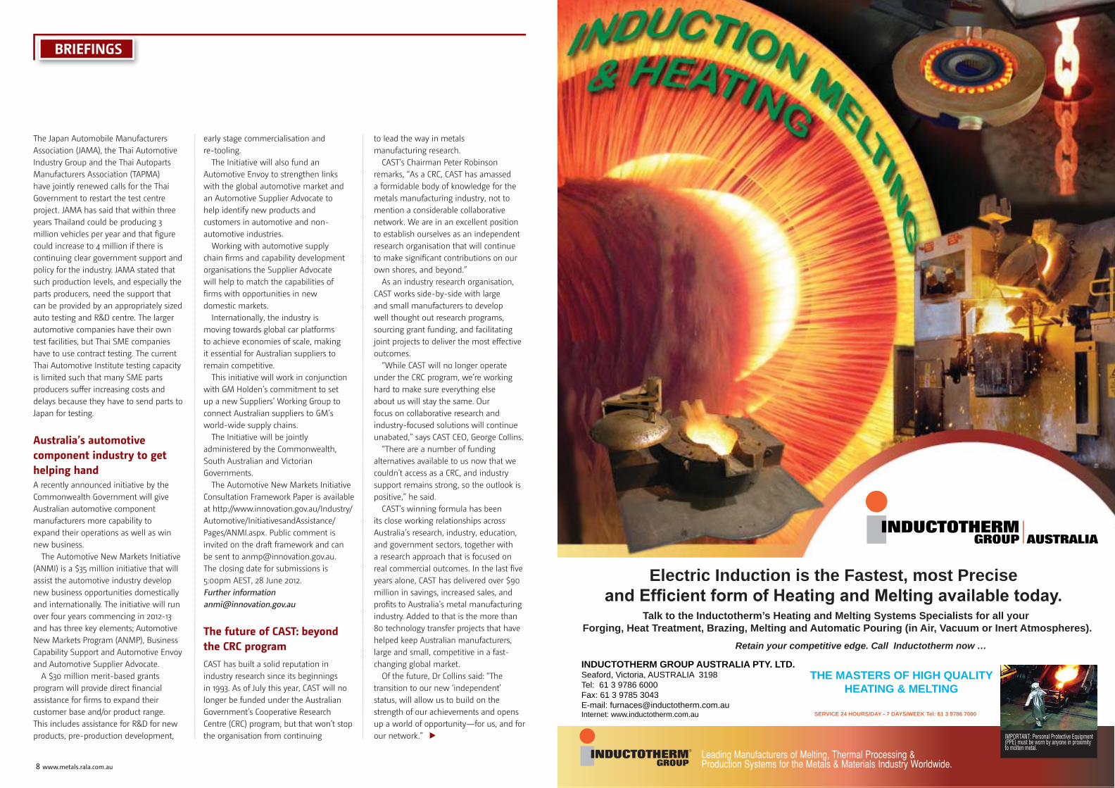
INDUCTOTHERM GROUP AUSTRALIA PTY. LTD.Seaford, Victoria, AUSTRALIA 3198Tel: 61 3 9786 6000Fax: 61 3 9785 3043E-mail: [email protected]: www.inductotherm.com.au
Electric Induction is the Fastest, most Precise
THE MASTERS OF HIGH QUALITY HEATING & MELTING
SERVICE 24 HOURS/DAY - 7 DAYS/WEEK Tel: 61 3 9786 7000
Retain your competitive edge. Call Inductotherm now …
Talk to the Inductotherm’s Heating and Melting Systems Specialists for all your Forging, Heat Treatment, Brazing, Melting and Automatic Pouring (in Air, Vacuum or Inert Atmospheres).
AUSTRALIA

10 www.metals.rala.com.au
TFA 2012 visits to industry begin in 3D
Each year the Thai Foundry Association organises a programme of technical visits to industry for its members. The 2012 season started in January with a look at rapid prototyping at Speed 3D Mold Co. Ltd. in Samutsakhon, near Bangkok. The company, which opened in 2011, offers casting simulation services and specialises in digital fabrication for complex sand moulds and cores via ink-jet printing technology starting directly from CAD data. In February the TFA paid visits to the Quality Sand Corporation Ltd and Siam Kubota plants just outside Bangkok. Quality Sand produce silica foundry sands and resin coated sand for shell moulding. Siam Kubota produces cast iron parts for agricultural machines, tractors and excavators.
Metal + Metallurgy China 2012 – Highly successful with strong growth Metal + Metallurgy China 2012 was held recently from 9-12 May at the China International Exhibition Centre in Beijing. The exhibition saw 1,375 exhibitors of which 1,109 companies were from China and the remaining 266 from countries around the world. Strong growth and support was represented by the growing number of 86,440 visitors attending up from 47,693 in 2010.
With stronger rising power, China has become the most important engine for global economic growth. In 2011, China kicked off its 12th Five-Year Plan (2011-2015). One of its targets is to speed up the construction & renovation of high speed rail networks, expressways, power grid and reservoir & irrigation systems. Great emphasis will be put on, and strict measures will be adopted for environmental protection, energy & resources saving, low carbon generation and scrap metal recycling to maintain the sustainable development of the metal and metallurgy industry and the whole economy at large.
Metal + Metallurgy China will return to Beijing in May 2014.
After the floods in Thailand – restarts, clusters and new estates?Following gradual recovery from the 2011 Thai flooding, the report of a survey by the Japanese Chamber of Commerce, Bangkok suggests that 85% of Japanese companies will continue to operate in Thailand with 8% of companies, mainly in the electronics sector, determined to relocate elsewhere. More than 400 of the 2,000 or so Japanese companies in Thailand have plants situated in the industrial estates that were severely affected by the flooding. It is estimated that just over half of the affected plants will have resumed production by the end of May 2012, but some companies will have had no production for more than six months due to the need for imported replacements of equipment or because they have yet to decide whether to restart existing plants or relocate. A number of companies have transferred production to alternative sites in Japan, China or other Asean countries. Japanese companies are paying increasing interest in Indonesia, due to the large domestic market, and Myanmar, due to natural resources and low labour costs.
In April Honda Automobile (Thailand) Company officially reopened its assembly plant in the Rojana Estate at Ayutthaya where production had to be stopped during early October 2011 when Rojana became the first industrial estate to be hit by the flooding. The Ayutthaya plant produces the Brio, Jazz, City, Civic, Accord and CRV models for the Thai market and for export to 30 other countries. The opening ceremony was attended by the Thai Prime Minister Yingluck Shinawatra, Mr. Takanobu Ito who is President of Honda Motors, and by Asian Honda Motor President & CEO Mr. Hiroshi Kobayashi, who is also president of Honda Automobile (Thailand). Mr. Ito stressed Thailand’s position as a very important production base in the region for Honda. He said that along with India and Indonesia, Thailand was among the three major markets for Honda in the Asia and Oceania region, and as such would continue as a main Honda production centre in the region.
BRIEFINGS
New technology in action at Speed 3D
Examples of rapid build moulds and cores FOUNDRY EQUIPMENT DIVISION PIPE HANDLING DIVISION
CORE-SHOOTING MACHINE DIVISION
I.M.F. Impianti Macchine Fonderia S.r.l. 21016 Luino (Va) Italy Ph.+ 39 0332 542424 Fax+ 39 0332 542626 [email protected] www.imf.it
SHOT-BLASTING MACHINE DIVISION
12 www.metals.rala.com.au
Other welcome news was that Siam Toyota Manufacturing, the local engine producer for Toyota vehicles in Thailand, is planning to increase the annual production of petrol engines by 100,000 units to 840,000. This will require an investment of some 6 billion baht and include the construction of a new aluminium alloy casting plant creating around 200 new jobs. The new facility will produce engines for vehicles to be assembled in Thailand, Vietnam and Taiwan.
Toyota Motor Thailand also announced that the refurbished Thai Auto Works (TAW) plant in Samut Prakarn would begin producing vehicles again by the end of 2012. The TAW plant built pick-up trucks and SUVs before it was mothballed in May 2010 due to the poor vehicle demand in the market at that time. It is believed that the re-opened plant will assemble Toyota commuter vans to substitute for imports totaling 20,000 vehicles per year that are currently built in Malaysia and Japan. It will be the first time that Toyota has assembled such vans in Thailand.
To establish back-up production facilities that can maintain parts supplies in the event of any future disaster the Japanese International Cooperation Agency (JICA) is promoting the set-up of “sister clusters” in Thailand. In normal times the sister cluster project, which is due to begin in 2013, will enable companies in the cluster to build up mutual business ties such they can operate as alternative production bases for one another in the event of a crisis. The project will be promoted by the industrial estate operators in Thailand and it is intended that small and medium sized companies will also be integrated into the clusters.
The Industrial Estates Authority of Thailand (IEAT) and the Thai Chamber of Commerce are involved in plans to set up a new industrial hub in the NE region of Thailand. New parts production bases in Udon Thani, Nakhon Ratchasima and Khon Kaen, etc. could supply existing assembly bases in the Eastern seaboard and could also serve as a gateway to Laos and Vietnam.
China shows signs of recovery in passenger vehicle salesFor the second straight month China’s passenger vehicle sales have increased more than was expected with a 13 percent rise in April to 1.3 million units. According to The China Association of Automobile Manufacturers analysts surveyed by Bloomberg news estimated an increase of only 11.3 percent.
Deputy Secretary General Yao Jie said the Association sees “signs of recovery” for sales in the world’s largest automotive market after they began the year with their worst two-month start since 2005. Toyota, Nissan Motor Co. and Honda Motor Co., which cut output at their Chinese factories after last year’s earthquake in Japan disrupted the supply of components, led gains as they restored production.
“Japanese carmakers were hit badly by the earthquake last year and that affected overall industry sales,” said Chen Liang, a Shanghai-based analyst at Huatai United Securities Co. “This comparison with a lower base helped sales register strong growth.”
Total vehicle deliveries in April, including commercial vehicles, rose 5.2 percent to 1.6 million units, the industry association said. Sales of SUVs jumped 34 percent, sedan sales rose 13 percent, while minivan sales fell 0.3 percent.
Passenger-vehicle sales rose 1.9 percent in the first four months of the year, CAAM said.
Forecast unchangedThe association kept its forecast for total vehicle sales to increase 8 percent this year. The slump in demand during the first two months of the year led Gu Xianghua, a deputy to the secretary general at CAAM, to say growth may not even reach 5 percent in 2012.
Auto demand rose 32 percent in 2010 after the government introduced subsidies and rebates to encourage buying, before slowing to 2.5 percent last year after the incentives lapsed.
General Motors, China’s largest foreign automaker, reported this week that sales
in country climbed 12 percent to 227,217 units, as demand for its Wuling minivans offset a drop in Chevrolet deliveries. The Buick Excelle was the top-selling model passenger vehicle model in China last month with 23,200 in deliveries, according to CAAM data.
Ford Motor Co.’s vehicle sales in China rose 24 percent to 54,881 units, the company said in an e-mailed release.
Among Japanese carmakers, Honda Motor Co. sold 43 percent more vehicles than a year earlier, Nissan Motor Co. boosted deliveries 18 percent, while Toyota increased sales by 68 percent.
“This time last year, the earthquake in Japan disrupted a large chunk of our production, comparison with the low base last year is the main reason for April’s big growth increase,” Niu Yu, the company’s Beijing-based spokesman.
Hyundai Motor Co.’s Verna and Elantra Yuedong were the only models by Asian carmakers to rank in the top 10 list last month, data from CAAM show.
Most luxury-car manufacturers continued to increase sales at a faster pace than mass-market carmakers.
BMW AG, which introduced the new generation long-wheelbase BMW 3-series sedan last month at the Beijing Auto show, saw sales rise 31 percent last month.
Volkswagen AG’s Audi delivered 44 percent more cars in the same period. Daimler AG’s Mercedes-Benz bucked the trend, registering an 8 percent decline in monthly sales.
- Source Automotive News China
Customer Day looks at melting and dust control in the foundryIn Bangkok, on 30th March 2012, ABP Induction Limited in partnership with Nederman S.E.A. Company organized a one day seminar for their customers in Thailand and members of the Thai Foundry Association. The morning session, conducted by speakers from ABP Induction Systems GmbH Germany (www.abpinduction.com), was entitled
BRIEFINGS BRIEFINGS
METAL Casting Technologies June 2012 13
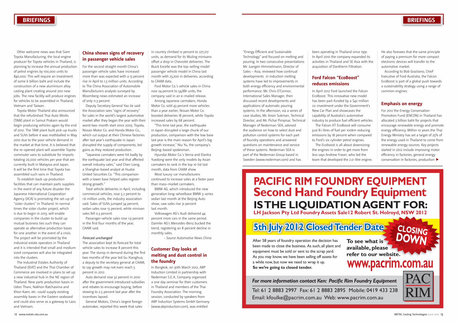
PACIFIC RIM FOUNDRY EQUIPMENT Second Hand Foundry EquipmentIS THE LIQUIDATION AGENT FOR:LH Jackson Pty Ltd Foundry Assets Sale12 Robert St. Holroyd, NSW 2012
For more information contact Ken: Pacifi c Rim Foundry Equipment
Tel: 61 2 8883 2997 Fax: 61 2 8883 2895 Mobile: 0419 433 238 Email: [email protected] Web: www.pacrim.com.au
After 58 years of foundry operation the decision has been made to close the business. As such, all plant and equipment must be sold or sent to the scrap yard. As you may know, we have been selling off assets for a while now, but now we need to wrap it up. So we’re going to closed tender.
To see what is available, please refer to our website.
www. rim.com.au
5th July 2012 Closed Tender Date
y ,
is ease website.
CLOSINGDOWN
“Energy Efficient and Sustainable Technology” and focused on melting and pouring. In two consecutive presentations Mr. Juergen Himmelmann, Director of Sales – Asia, reviewed how continual developments in induction melting systems have led to improvements in both energy efficiency and environmental performance. Mr. Chris O’Connor, International Sales Manager, then discussed recent developments and applications of automatic pouring systems. In the afternoon, via a series of case studies, Mr. Anon Sukman, Technical Director, and Mr. Pichai Pimpisai, Technical Manager of Nederman SEA, advised the audience on how to select dust and pollution control systems for each part of foundry operations and answered questions on maintenance and service of these systems. Nederman SEA is part of the Nederman Group based in Sweden (www.nederman.com) and has
been operating in Thailand since 1991. In April 2010 the company expanded its activities in Thailand and SE Asia with the acquisition of Dantherm Filtration.
Ford Falcon “EcoBoost” reduces emissionsIn April 2012 Ford launched the Falcon EcoBoost. This innovative new model has been part-funded by a $42 million co-investment under the Government’s New Car Plan and showcases the capability of Australia’s automotive industry to produce fuel efficient vehicles.
The Falcon XT EcoBoost will consume just 8.1 litres of fuel per 100km reducing emissions by 18 percent when compared to Ford’s six cylinder petrol engines.
The Ecoboost is all about downsizing the engines in order to get more from less says Andrew Fraser, who led the team that developed the 2.0-litre engine.
He also foresees that the same principle of paying a premium for more compact electronic devices will transfer to the automotive market.
According to Bob Graziiano, Chief Executive of Ford Australia, the Falcon EcoBoost is part of a global push towards a sustainability strategy using a range of common engines.
Emphasis on energyFor 2012 the Energy Conservation Promotion Fund (ENCON) in Thailand has allocated 3 billion baht for projects that encourage renewable energy and promote energy efficiency. Within 10 years the Thai Energy Ministry has set a target of 25% of the energy used in Thailand to come from renewable energy sources. Key projects started in 2012 include improving motor efficiency in factories, general energy conservation in factories, production
SUBSCRIPTION WINNER Congratulations to the University of Technology Sydney, Australia who is the winner of our Special Renewal Offer for June 2012 renewals. The University will receive a complimentary one year subscription to the Metals magazine.
of compressed bio-methane gas (CBG) for vehicles in remote areas with limited access to compressed natural gas, and use of solar energy to heat water. A renewed public relations campaign will also be used to raise public awareness about energy conservation and efficiency.
In March 2012 Thailand hosted a regional workshop in Bangkok, attended by 140 delegates from 8 countries, on the production and use of jatropha bio-diesel fuel. The event was co-organized by the New Energy and Industrial technology Development Organization (NEDO) of Japan and MTEC- the National Metals and Materials Technology Centre of Thailand with the aims of reviewing the present status and future prospects of bio-fuel production and discussing bio-mass policies in ASEAN countries, as well as providing a forum for networking and collaboration between jatropha bio-diesel research workers.
Energy and environment are two of the areas covered by the 7th Framework Programme for Research and Technological Development (FP7) which was originally launched in 2007 by the European Union. To encourage more cooperation in technology and innovation between the EU and SE Asia 2012 will be known as “Asean-EU Year of Science, Technology and Innovation”. This summer a further 10 billion Euros will be available in the last call for research proposals under FP7. In 2014 a new programme called Horizon 2020 will replace FP7. Horizon 2020 will focus on 3 key areas: science, industrial leadership and challenges to society. Among the Horizon 2020 topic areas of interest to metal casters are advanced materials and manufacturing processes, nanotechnology, secure clean and efficient energy, raw materials and resource efficiency. Of the Asean countries Thailand currently has the highest participation in FP7, followed by Indonesia and Vietnam. In Thailand the National Science and Technology Development Agency (NSTDA) has set up an FP7 Support Office to encourage and support Thai research workers who would like to take part in FP7 funded projects.
Honda to build new car and engine plants in ChinaHonda Motor Co plans to start construction of a new car and a new engine plant in China by the end of 2012 which is expected to be operational by 2014. Spending USD560 million to build the new plants the Japanese automaker anticipates that annual production will increase by 25%. Guangqi Honda Automobile Co, a Chinese joint venture with Honda, plans to boost the annual production to 600,000 vehicles in 2014 from the current 480,000.
Launching 10 new car models between now and 2015 Honda expects the 2011 annual recorded sales in China to double the recorded sales in 2011. ■
BRIEFINGS

16 www.metals.rala.com.au
Trust your most complex cores to INCAST ®. The idealcombination of geometry, density and particle size distribution, INCAST improves critical core making and casting propertiesincluding binder utilization, permeability and dimensional stability. Higher strength cores, better surface finish and increased efficiency and yield are the INCAST advantages.These sands are engineered for the metalcaster.
Optimize CorePerformance
For more information and availability:[email protected]
CORE AND MOULDING SANDS
® INCAST is a trademark. All rights reserved. ©2011
®
TECHNICAL FEATURE
Introductionhe Thai Foundry Association has around 100 company members in the non-ferrous sector, with around 90% of these producing Aluminium Alloy automotive
and electronic parts by high pressure diecasting. Low pressure diecasting and a limited amount of gravity casting processes are also used to produce car and truck wheels. The larger Al casting companies are joint ventures, mainly with Japan, and as such, serve as production bases having little involvement in research. Likewise the Thai owned SME Al foundries do not carry out any R&D by themselves but an increasing number of them are turning to the university sector for help in solving production problems. Three years ago the Thai Foundry Association set up the Aluminium Technology Forum to encourage capability improvements in light metal foundries. This Forum has improved technical knowledge through visits, seminars and training but most Aluminium casting research continues to be limited to university post-graduate projects or is performed in government supported centres such as the National Metal and Materials Technology Centre (MTEC). This article provides a brief outline of some of this research.
Improving melt quality and process controlR&D work at MTEC remains focused on helping Thai SME aluminium casting producers to improve their melt preparation, liquid metal treatments, process controls and technical capability in general [1]. Dr. J. Kajornchaiyakul leads a foundry engineering research group which has continued to provide improved and affordable thermal analysis systems for small foundries based on in-house developed AlRite and AlSoft equipment and software [2]. Following on from previous observations in predicting grain size [3] ongoing work is examining the various factors (e.g. H content, pouring
temperature and cooling rate) that may influence the nature of measured cooling curves and hence the reliability of grain refinement measurements. Various test techniques to assess liquid metal fluidity and cleanliness are also being examined, for example, a ring casting test has been developed to study quality in high pressure diecasting [4]. The simulation and design group directed by Dr. P. Dulapraphant at MTEC is involved in designing improved running and feeding systems for Al foundries. A current study is looking at how gating systems in HPDC affect machine power, die wear, flash and casting integrity, etc. This group also co-operates in the university research work in semi-solid processing outlined in the following section.
Semi-solid processingThe Innovative Metal Technology Centre led by Dr. J. Wannasin at Prince of Songkla University (PSU) in Hat Yai in the south of Thailand concentrates on semi-solid processing R&D using the gas-induced semi-solid (GISS) method. Feasibility studies have shown that the GISS process can not only be readily applied to produce Al alloy parts by high pressure diecasting [5] but can also be used for gravity sand casting [6, 7]. In HPDC the main advantages are found to be reduced turbulent flow giving improved die filling and in sand casting better casting yield plus improved mechanical properties. Recent work has centered on how the formation of solid fractions in the slurry can be characterized and modeled using a combination of rapid quenching and dilation & counting techniques [8]. Such characterization should lead to improved process control of slurry preparation and also assist process optimization. The effects of solution treatment and aging on the mechanical behaviour of GISS cast parts in several Al alloys are also being studied to determine optimum heat treatment conditions [9-11].
Grain refi nement and structural modifi cationA number of projects on control of cast structures in Al alloys have been completed at the Centre of Excellence in Metal Casting Technology at King Mongut’s University of Technology Thonburi (KMUTT). Postgraduate work supervised by Dr. C. Limmaneevichitr has investigated the effects of treatments with elements such as Antimony and Scandium on castability, mechanical properties and response to solution and aging heat treatments [12, 13]. As an alternative to semi-solid processing, the use of mechanical vibration during solidification is also being studied. Vibration of a pasty A356 melt with adequate solid fraction prior to completion of solidification was found to produce similar microstructures to semi-sold processing [14].
Characterisation of precipitation sequences during heat treatmentCharacterisation of fine scale microstructural features is essential in understanding the changes in structure and properties that occur during heat treatment of castings. In the north of Thailand, Dr. T. Chairuangsri at Chiang Mai University and Dr. A. Wiengmoon at Naruesuan University in Phitsanulok lead small research groups looking at how transmission electron microscopy (TEM) and related techniques can provide useful information about fine scale precipitates and second phases in casting alloys such as alloy white irons, duplex stainless steels and Al base. Both groups benefit from excellent co-operation via a post-graduate exchange scheme with the Advanced Research Centre for Beam Science at the Institute for Chemical Research, Kyoto University, Japan. The work on Al alloys, involving both conventionally cast and semi-solid cast materials, is focused on studies of precipitation sequences during aging of solution treated cast material, and the effects on mechanical properties [15-19]. Typical changes [16] in micro-hardness during aging of solution treated A319 alloy (Al-5%Si-3.5%Cu) are shown in Figure 1. Thai researchers visiting Kyoto University can make use of specialized techniques such as high resolution transmission electron microscopy (HRTEM) and high angle annular dark field scanning transmission electron microscopy (HAAD-STEM). These instruments enable not only the identification of precipitates by electron diffraction but also provide images of atomic positions within a precipitate and in the surrounding matrix, for
Recent aluminium castings research in ThailandBy John Pearce
T
R&D WORK AT MTEC REMAINS FOCUSED ON HELPING THAI SME ALUMINIUM CASTING PRODUCERS TO IMPROVE THEIR MELT PREPARATION, LIQUID METAL TREATMENTS, PROCESS CONTROLS AND TECHNICAL CAPABILITY IN GENERAL.

18 www.metals.rala.com.au METAL Casting Technologies June 2012 19
SuperchargeYour GreenSand SystemGreen sand systems work harder and last longer withTRUBOND®. These sodium bentonite grades mull in quicklyand undergo a controlled hydration to develop a stronger,more elastic adhesive. TRUBOND delivers excellent green compressive and hot strength properties and maintains itsworking bond in repetitive exposure to high heat loads and metal temperatures.
SODIUM BENTONITE
For more information and availability:[email protected]
® TRUBOND is a registered trademark. All rights reserved. ©2011
TECHNICAL FEATURE
example in alloys A356 [18] and A319 [19]. An example from work [18] that has made use of HRTEM imaging of precipitates in A356 alloy (Al-7%Si-0.3%Mg) is given in Figure 2. Such information leads to improved understanding about how the formation of precipitates affects mechanical properties since the degree of atomic fit/misfit between the precipitate and the surrounding matrix can be determined.
Future workAcademic research into aluminium alloy castings is well established in some Thai universities and it is important for the development of Thai metallurgical engineers that this work will continue to receive funding. At the same time Thai SMEs producing Al castings should seek increased contact with the “academics” to draw on expertise gained through research such as that outlined above. In optimizing their process conditions Thai metal casters could also benefit by taking a more “scientific”, rather than “guesswork”, approach to their control of variables. Thai universities and organizations like MTEC can all offer advice and guidance on how to design and carry out experiments for such shop floor R&D. However the first hurdle, as always, is to convince companies that in the longer term the effort expended in doing this work is more efficient in materials, energy and cost than “firefighting”.
At the time of writing Dr. J. Wannasin, who specialises in semi-solid metal technology at PSU, is the lead organizer of a one day seminar for industry to be held on June 5th at the Bureau of Supporting Industries Development in Bangkok. The seminar will examine “Advances and Technologies in Aluminium Casting”. Among the invited speakers are Prof. Merton Flemings, Massachusetts Institute of Technology (MIT) and Mr. Asia Mikio, Vice-President (Materials Engineering Division) of Toyota Motor Asia Pacific Engineering & Manufacturing. The seminar will wind up with a panel discussion on “Strengths, Weaknesses, Opportunities and Threats in the Thai Aluminium Casting Industry. A full report of this event and comment on the responses of industrial delegates during the panel discussion, including attitudes towards R&D, will be sent for inclusion in the September issue of MCT. ■
REFERENCES
1. J. Kajornchaiyakul & J. Pearce. “R&D to Improve Capability in Thai Aluminium Foundries”. Metal Casting Technologies (2010) Vol.56 No.2 June pp.36-39
2. J. Pearce. “Developing Thai R&D in Aluminium Castings”. Metal Casting Technologies (2009) Vol.55 No.2 June, pp. 36-39.
3. S. Phetchcrai et al. “Towards Improving the Thermal Analysis Technique in Casting of Hypoeutectic Aluminium-Silicon Alloy”. Metal Casting Technologies (2011) Vol.57 No.2 June, pp.24-28.
4. S. Lounksonchai et al. “Use of a die-casting ring test piece to study aluminium alloy melt quality”. Metal Casting Technologies (2012) Vol.58 No.1 March, pp. 24-27.
5. J. Wannasin et al. “Research and development of gas induced semi-solid process for industrial applications”. Trans. Nonferrous Met. Soc. China (2010) Vol. 20 pp.s1010-1015.
6. T. Chucheep et al. “Semi-solid gravity sand casting using gas induced semi-solid process”. Trans. Nonferrous Met. Soc. China (2010) Vol. 20 pp.s 981-987.
7. T. Chucheep et al. “A fluidity study of semi-solid rheo-slurry of AC4C aluminium alloy in gravity sand casting”. Advanced Materials Research (2011) Vol. 337 pp.439-442.
8. R. Canyook et al. “Characterisation of the microstructure evolution of a semi-solid metal slurry during the early stages”. Acta Materialia (2012) Vol. 60 pp. 3501-3510.
9. N. Mahalthaninwong et al. “Influence of solution treatment on microstructures of semisolid cast 7075 aluminium alloy”. Advanced Materials Research (2011) Vol.337 pp.439-442.
10. N. Mahalthaninwong et al. “T6 heat treatment of rheocasting 7075 alloy”. Materials Science & Engineering A (2012) Vol. 532 pp.91-99.
11. S. Wisulmethangoon et al. “Precipitation hardening of A356 Al alloy produced by gas induced semi-solid process”. Materials Science & Engineering A (2012) Vol. 532 pp.610-615.
12. S. Boontein et al. “Reduction in secondary dendrite arm spacing in cast aluminium alloy A356 by Sb addition”. Int. J. of Cast Metals Research (2011) Vol.24 pp.108-112.
13. W. Prukkanon et al. “Influence of Sc modification on the fluidity of an A356 aluminium alloy”. J. of Alloys & Compounds (2009) Vol.487 pp.453-457.
14. C. Limmaneevichitr et al. “Metallurgical structure of A356 aluminium alloy solidified under mechanical vibration: an investigation of alternative semi-solid casting routes”. Materials & Design (2009) Vol.30 pp.3925-3930.
15. S. Imurai et al. “Age hardening and precipitation behaviour of an experimental cast Al-Si-Mg alloy treated by T6 and T6I6 heat treatments”. Chiang Mai Journal of Science (2010) Vol. 37(2) pp.269-281.
16. P. Apichai et al. “Effect of Precipitation Hardening Temperatures and Times on Microstructure, Hardness and Tensile Properties of Cast Aluminium Alloy A319”. Naresuan University Engineering Journal (2011) Vol.6 pp.28-33.
17. P. Apichai et al. “Effect of Solution Treatment and Aging on Microstructure and Mechanical Properties of Cast Aluminium Alloy A319”. Proceedings of the European Conference on Heat Treatment 2011 “Quality in Heat Treatment”, 23-25 March 2011, Wels, Austria, pp. 218-225.
18. N. Chomsaeng et al. “HRTEM and ADF-STEM of precipitates at peak aging in cast A356 alloy”. J. of Alloys & Compounds (2010) Vol.496 pp.478-487.
19. A.Wiengmoon et al. “HRTEM and HAADF-STEM Study of the Precipitate at Peak Aging of Cast A319 Aluminium Alloy”. Conference Proceedings APMC 10 - The 10th Asia-Pacific Microscopy Conference, 6-9 February 2012, Perth, Western Australia, pp.199/1-2.
Figure 1. Effect of aging temperature and time on micro-hardness of solution treated A319 alloy. After Apichai [17]
Figure 2. An example of HRTEM imaging of precipitates formed in the Al solid solution matrix during aging of solution treated A356 alloy. The regular array of dark contrast corresponds to the positions of Al atoms (orientation indicated by white arrows). The outlined area shows a precipitate identified by nano-electron diffraction (from area 3-4nm in size) as β double dash Mg5Si6. The inset is a model of the diffraction pattern from the precipitate and Al matrix. This study was performed by N. Chomsaeng as part of his PhD studies (Chiang Mai University) during an exchange period at Kyoto [18].
THAI UNIVERSITIES AND ORGANIZATIONS LIKE MTEC CAN ALL OFFER ADVICE AND GUIDANCE ON HOW TO DESIGN AND CARRY OUT EXPERIMENTS FOR SUCH SHOP FLOOR R&D.
20 www.metals.rala.com.au
required for production then costs may be an issue.With regards to castability, an alloy with excellent creep
resistance that is unable to form acceptable parts due to cracking or filling problems is also unsuitable for commercial application.
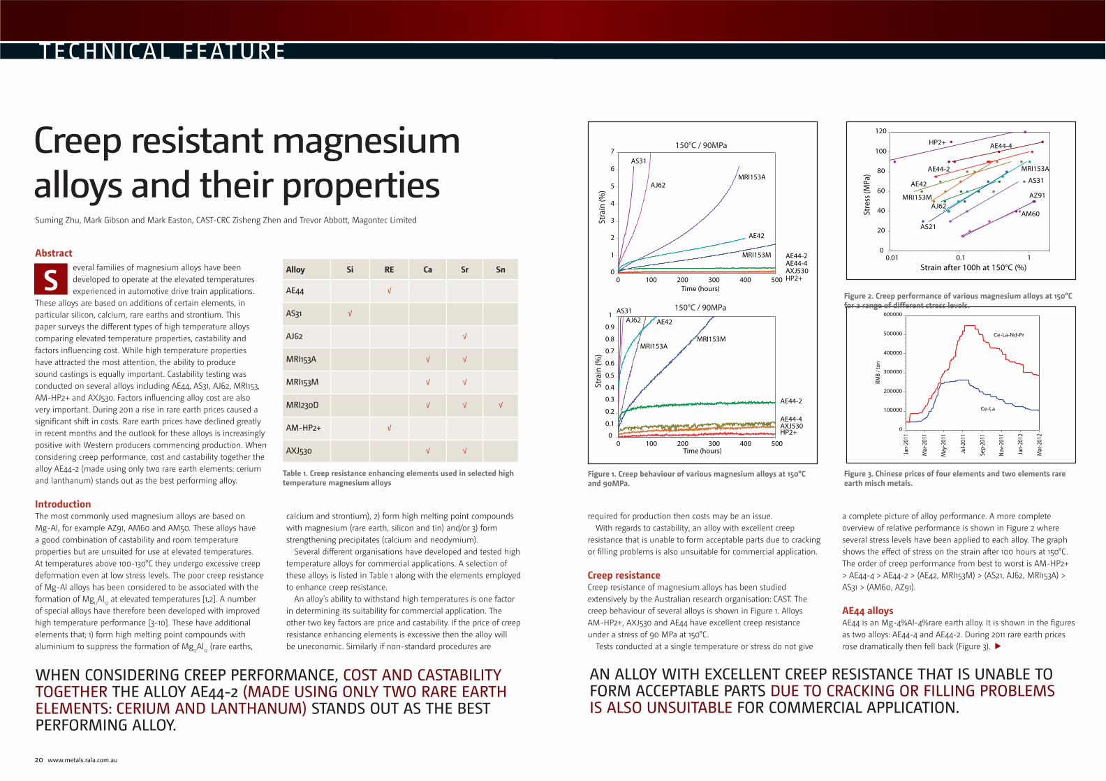
Creep resistanceCreep resistance of magnesium alloys has been studied extensively by the Australian research organisation: CAST. The creep behaviour of several alloys is shown in Figure 1. Alloys AM-HP2+, AXJ530 and AE44 have excellent creep resistance under a stress of 90 MPa at 150°C.
Tests conducted at a single temperature or stress do not give
a complete picture of alloy performance. A more complete overview of relative performance is shown in Figure 2 where several stress levels have been applied to each alloy. The graph shows the effect of stress on the strain after 100 hours at 150°C. The order of creep performance from best to worst is AM-HP2+ > AE44-4 > AE44-2 > (AE42, MRI153M) > (AS21, AJ62, MRI153A) > AS31 > (AM60, AZ91).
AE44 alloys AE44 is an Mg-4%Al-4%rare earth alloy. It is shown in the figures as two alloys: AE44-4 and AE44-2. During 2011 rare earth prices rose dramatically then fell back (Figure 3).
0
0.1
0.2
0.3
0.4
0.5
0.6
0.7
0.8
0.9
1
0 100 200 300 400 500
Stra
in (%
)
Time (hours)
AS31
AJ62
MRI153AMRI153M
AE42
AE44-2
AE44-4AXJ530HP2+
150°C / 90MPa
0
1
2
3
4
5
6
7
0 100 200 300 400 500
Stra
in (
%)
Time (hours)
AS31
AJ62MRI153A
MRI153M
AE42
AE44-2AE44-4AXJ530HP2+
150°C / 90MPa
J
J
JJ
J
J
J
J
J
J
J
J
J
J
J
J
J
J
J
J
J
J
J
J
J
J
J
J
J
J
J
J
J
J
J
J
JJ
J
JJ
J
J
J
J
J
0
20
40
60
80
100
120
0.01 0.1 1
Stre
ss (M
Pa)
Strain after 100h at 150°C (%)
AZ91
AM60
AS31
AS21
MRI153A
AJ62
AE42
MRI153M
AE44-2
AE44-4HP2+
0
100000
200000
300000
400000
500000
600000
Jan
-201
1
Mar
-201
1
May
-201
1
Jul-2
011
Sep
-201
1
Nov
-201
1
Jan
-201
2
Mar
-201
2
RMB
/ to
n
Ce-La
Ce-La-Nd-Pr
Figure 1. Creep behaviour of various magnesium alloys at 150°C and 90MPa.
Figure 2. Creep performance of various magnesium alloys at 150°C for a range of different stress levels.
Figure 3. Chinese prices of four elements and two elements rare earth misch metals.
AN ALLOY WITH EXCELLENT CREEP RESISTANCE THAT IS UNABLE TO FORM ACCEPTABLE PARTS DUE TO CRACKING OR FILLING PROBLEMS IS ALSO UNSUITABLE FOR COMMERCIAL APPLICATION.
TECHNICAL FEATURE
Abstracteveral families of magnesium alloys have been developed to operate at the elevated temperatures experienced in automotive drive train applications.
These alloys are based on additions of certain elements, in particular silicon, calcium, rare earths and strontium. This paper surveys the different types of high temperature alloys comparing elevated temperature properties, castability and factors influencing cost. While high temperature properties have attracted the most attention, the ability to produce sound castings is equally important. Castability testing was conducted on several alloys including AE44, AS31, AJ62, MRI153, AM-HP2+ and AXJ530. Factors influencing alloy cost are also very important. During 2011 a rise in rare earth prices caused a significant shift in costs. Rare earth prices have declined greatly in recent months and the outlook for these alloys is increasingly positive with Western producers commencing production. When considering creep performance, cost and castability together the alloy AE44-2 (made using only two rare earth elements: cerium and lanthanum) stands out as the best performing alloy.
IntroductionThe most commonly used magnesium alloys are based on Mg-Al, for example AZ91, AM60 and AM50. These alloys have a good combination of castability and room temperature properties but are unsuited for use at elevated temperatures. At temperatures above 100-130°C they undergo excessive creep deformation even at low stress levels. The poor creep resistance of Mg-Al alloys has been considered to be associated with the formation of Mg17Al12 at elevated temperatures [1,2]. A number of special alloys have therefore been developed with improved high temperature performance [3-10]. These have additional elements that; 1) form high melting point compounds with aluminium to suppress the formation of Mg17Al12 (rare earths,
calcium and strontium), 2) form high melting point compounds with magnesium (rare earth, silicon and tin) and/or 3) form strengthening precipitates (calcium and neodymium).
Several different organisations have developed and tested high temperature alloys for commercial applications. A selection of these alloys is listed in Table 1 along with the elements employed to enhance creep resistance.
An alloy’s ability to withstand high temperatures is one factor in determining its suitability for commercial application. The other two key factors are price and castability. If the price of creep resistance enhancing elements is excessive then the alloy will be uneconomic. Similarly if non-standard procedures are
Creep resistant magnesium alloys and their properties
S Alloy Si RE Ca Sr Sn
AE44 √
AS31 √
AJ62 √
MRI153A √ √
MRI153M √ √
MRI230D √ √ √
AM-HP2+ √
AXJ530 √ √
Table 1. Creep resistance enhancing elements used in selected high temperature magnesium alloys
WHEN CONSIDERING CREEP PERFORMANCE, COST AND CASTABILITY TOGETHER THE ALLOY AE44-2 (MADE USING ONLY TWO RARE EARTH ELEMENTS: CERIUM AND LANTHANUM) STANDS OUT AS THE BEST PERFORMING ALLOY.
Suming Zhu, Mark Gibson and Mark Easton, CAST-CRC Zisheng Zhen and Trevor Abbott, Magontec Limited
22 www.metals.rala.com.au
TECHNICAL FEATURE
Rare earths typically occur as a mixture of elements with cerium being the most abundant followed by lanthanum, neodymium and praseodymium. Traditionally the lowest cost rare earth metal has been that obtained by direct conversion of the ore to metal without separation of individual elements. However, in recent years the increased demand for neodymium has led to two elements misch metal, containing just cerium and lanthanum, becoming considerably cheaper than four elements misch metal.
In view of these developments AE44 is now provided in
two versions. AE44-4 contains Ce, La, Nd and Pr while AE44-2 contains just Ce and La.
While the creep performance of AE44-2 is reduced from AE44-4 it still exceeds the performance of all other alloys apart from AXJ530 and AM-HP2+. When die castability is considered the benefits of AE44-2 over other alloys is greatly enhanced.
Die castabilityIn some alloys, high temperature creep resistance comes at the expense of castability. If an alloy is prone to cracking or does not easily fill the die then high temperature creep resistance is of little use.
Quantification of die castability is not as straightforward as determining creep properties. Castability refers the several different aspects including tendency for cracking, level of porosity, fluidity and ease of filling, resistance to sticking and die soldering, surface finish and melt handling (including oxidation resistance and tendency for clogging problems in the melt transfer system).
In addition to different measures of castability, differences
AZ
91
D
AE
44
AJ5
2
AX
J53
0
MR
I15
3A
MR
I15
3M
MR
I23
0D
AS
31
HP
2+
0
1
2
3
4
5
Ca
sta
bili
ty R
ati
ng
cracking
lling
1
1
1
1
1
1
1
1
10
20
40
60
80
100
120
1.5 2 2.5 3 3.5 4
Cre
ep
Str
en
gth
(M
Pa
)
Castability Index
AM-HP2+
AE44
1%Ca
1%Ca
2%Ca3%Ca
MRI230D
AXJ530
MRI153M
AJ62MRI153A
AS31
AZ91
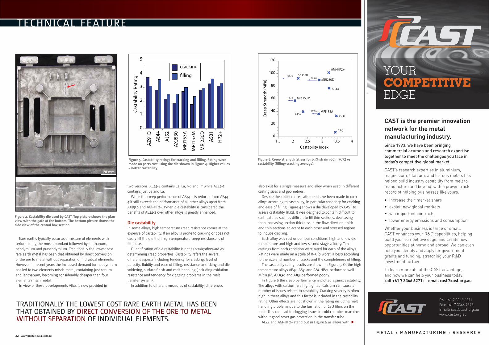
Figure 4. Castability die used by CAST. Top picture shows the plan view with the gate at the bottom. The bottom picture shows the side view of the central box section.
Figure 5. Castability ratings for cracking and filling. Rating were made on parts cast using the die shown in Figure 4. Higher values = better castability
Figure 6. Creep strength (stress for 0.1% strain 100h 175°C) vs castability (filling+cracking average).
also exist for a single measure and alloy when used in different casting sizes and geometries.
Despite these differences, attempts have been made to rank alloys according to castability, in particular tendency for cracking and ease of filling. Figure 4 shows a die developed by CAST to assess castability [11,12]. It was designed to contain difficult to cast features such as difficult to fill thin sections, decreasing then increasing section thickness in the flow direction, thick and thin sections adjacent to each other and stressed regions to induce cracking.
Each alloy was cast under four conditions: high and low die temperature and high and low second stage velocity. Ten castings from each condition were rated for each of the alloys. Ratings were made on a scale of 0-5 (0 worst, 5 best) according to the size and number of cracks and the completeness of filling.
The castability rating results are shown in Figure 5. Of the high temperature alloys AE44, AS31 and AM-HP2+ performed well. MRI153M, AXJ530 and AJ52 performed poorly.
In Figure 6 the creep performance is plotted against castability. The alloys with calcium are highlighted. Calcium can cause a number of issues related to castability. Cracking severity is often high in these alloys and this factor is included in the castability rating. Other effects are not shown in the rating including melt handling problems due to the formation of CaO films on the melt. This can lead to clogging issues in cold chamber machines without good cover gas protection in the transfer tube.
AE44 and AM-HP2+ stand out in Figure 6 as alloys with
TRADITIONALLY THE LOWEST COST RARE EARTH METAL HAS BEEN THAT OBTAINED BY DIRECT CONVERSION OF THE ORE TO METAL WITHOUT SEPARATION OF INDIVIDUAL ELEMENTS.
CAST is the premier innovation
network for the metal
manufacturing industry.
Since 1993, we have been bringing
commercial acumen and research expertise
together to meet the challenges you face in
today’s competitive global market.
CAST’s research expertise in aluminium,
magnesium, titanium, and ferrous metals has
helped build industry capability from melt to
manufacture and beyond, with a proven track
record of helping businesses like yours:
• increase their market share
• exploit new global markets
• win important contracts
• lower energy emissions and consumption.
Whether your business is large or small,
CAST enhances your R&D capabilities, helping
build your competitive edge, and create new
opportunities at home and abroad. We can even
help you identify and apply for government
grants and funding, stretching your R&D
investment further.
To learn more about the CAST advantage,
and how we can help your business today,
call +61 7 3366 6271 or email [email protected]
YOURCOMPETITIVEEDGE
M E T A L : M A N U F A C T U R I N G : R E S E A R C H
Ph: +61 7 3366 6271
Fax: +61 7 3346 9373
Email: [email protected]
www.cast.org.au

24 www.metals.rala.com.au
TECHNICAL FEATURE
both good creep properties and good castability. AS31 rates particularly well in terms of this castability test but has poor creep resistance.
CostThe cost of an alloy is as important as properties, especially in automotive applications. The recent rare earth price fluctuations mentioned above were of concern during 2011 but are now trending downwards (Figure 3). Additionally, non-Chinese rare earth
producers are also coming on-line in US, Australia, Malaysia and elsewhere which should help stabilise the price.
In Figure 7 an approximate indication of alloy cost is shown. The prices shown are the cost of alloy ingredients relative to AZ91D ingredients (March 2012 prices). This cost does not include production cost or yield losses and so should be used as a rough guide only. AM-HP2+, AE44-4 (Ce-La-Nd-Pr) and MRI230D are all considerably more expensive than AZ91D. AE44-2 (Ce-La) is much lower cost than AE44-4 and represents the best all round combination of creep properties, castability and cost.
AXJ530, MRI153M, AJ62, MRI153A and AS31 all have low cost ingredients but are limited by poor castability and/or poor creep properties.
ConclusionsFor a high temperature magnesium alloy to be adopted in automotive applications it needs to satisfy several criteria. Arguably the most important are creep resistance, castability and cost. The magnesium-aluminium-rare earth alloy AE44-2 (rare earths = Ce, La) uniquely meets all three criteria with good castability, creep resistance and cost.
In situations where creep resistance is of greatest importance the alloy AM-HP2+ stands against other high pressure diecast alloys. It exhibits both good castability and unmatched creep resistance but at a significantly higher price than AE44-2. ■
METAL Casting Technologies June 2012 25
REFERENCES
1. P. Humble: Mater. Forum, 1997, vol. 21, pp. 45-56.
2. M.S. Dargusch, G.L. Dunlop, and K. Pettersen: in Magnesium Alloys and Applications, B.L. Mordike and K.U. Kainer, eds., Werkstoff-Informationsgesellschaft, Frankfurt, Germany, 1998, pp. 277-82.
3. T.K. Aune and T.J. Ruden: SAE Trans., 1992, vol. 101, pp. 1-7.
4. M.O. Pekguleryuz and J. Renaud: in Magnesium Technology 2000, H.I. Kaplan, J. Hryn, and B. Clow, eds., TMS, Warrendale, PA, 2000, pp. 279-84.
5. E. Baril, P. Labelle, and M.O. Pekguleryuz: JOM, 2003, vol. 55(11), pp. 34-39.
6. B.R. Powell, A.A. Luo, V. Rezhets, J.J. Bommarito, and B.L. Tiwari: SAE Trans., 2001, vol. 110, pp. 406-13.
7. P. Bakke and H. Westengen: in Magnesium Technology 2005, N.R. Neelameggham, H.I. Kaplan, and B.R. Powell, eds., TMS, Warrendale, PA, 2005, pp. 291-95.
8. P. Lyon, J.F. King, and K. Nuttall: in Procedinging of the 3rd International Magnesium Conference, Institute of Materials, London, UK, 1996, pp. 99-108.
9. M.A. Gibson, C.J. Bettles, M.T. Murray, and G.L. Dunlop: in Magnesium Technology 2006, A.A. Luo, N.R. Neelameggham, and R.S. Beals, eds., TMS, Warrendale, PA, (2006), p. 327-31.
10. M.A. Gibson, S.M. Zhu, and J.F. Nie: in Proceedings of the Light Metals Technology Conference 2007, Saint-Sauveur, Québec, Canada, 2007, pp. 35-40.
11. M. Gibson, M.A. Easton, V. Tyagi, M. Murray, and G. Dunlop, in Magnesium Technology 2008, M. Pekguleryuz, E. Nyberg, R. S. Beals, and N. Neelameggham, eds., TMS, Warrendale, PA, 2008, pp. 227-232.
12. Strobel K, Easton MA, Tyagi V, Murray MT, Gibson MA, Savage G, Abbott T. Int. J. Cast Met. Res. 2010;23:81.
Reprinted with permission from the Proceedings of the 69th Annual International World Magnesium Conference, published by the International Magnesium Association.
1
111
1
11
1
1
0
20
40
60
80
100
120
1 1.2 1.4 1.6 1.8 2
Stre
ss (M
Pa) f
or 0
.1%
Cre
ep a
t 175
C af
ter 1
00 h
ours
Alloy Ingredient Cost / AZ91 Ingredient Cost
AM-HP2+
MRI230D
AXJ530
AE44-2
MRI153M
AJ62
MRI153AAS31
AZ91
1 AE44-4
Figure 7. Creep performance plotted against alloy ingredient prices. The data relates to prices in March 2012 and does not include contributions from processing costs or yield losses.
Dr Suming Zhu, CAST CRC Research Fellow, Monash UniversityDr Zhu received his PhD from City University of Hong Kong in 1997. Prior to joining Monash, he worked as lecturer at Dalian University of Technology, a research associate at City University of Hong Kong, and an industrial research scientist at Japan Ultra-High Temperature Materials Research Institute. Dr Zhu’s primary research focus is on microstructure and mechanical behaviour of structural metal alloys. His current research work is in magnesium alloys, including their mechanical properties and strengthening mechanisms, creep behaviour and deformation mechanisms, and micro-structural characterisation by electron microscopy.
Dr Mark Gibson, Research Group Leader Process Science & Engineering, CSIRODr Gibson gained his PhD from the University of Wollongong in 1989, joining CSIRO shortly after. In his current role, Dr Gibson is engaged in a number of research activities relating to the manipulation of alloy microstructure through careful control of composition and processing to optimise targeted functional properties. This has largely been associated with magnesium alloy development for light-weight automotive applications; however it is now extending more broadly into titanium alloys and non-equilibrium processing.
Dr Mark Easton, Program Manager Automotive Applications, CAST CRCDr Easton graduated with a PhD from The University of Queensland in 1999. Since then, he has worked in the light metals industry and in research organisations. He has been a research program manager with CAST CRC for the past seven years, a role which has included the oversight of magnesium alloy development activities. His research interests focus on metals processing, particularly casting, and how the developed microstructure affects alloy properties. Dr Easton won the prestigious GKSS International Magnesium Award in 2009.
Dr Zisheng Zhen, Technical Director, Magontec AsiaDr Zhen gained his PhD in materials science and engineering from University of Science and Technology Beijing, China, in 2003. He then conducted further research work on magnesium alloys at Oxford and Brunel Universities in England, and at the GKSS Magnesium Innovation Center in Germany. In 2009, Dr Zhen became the Manager of Research and Development at Magontec Xi’an. He took up his current role as Technical Director, Magontec Asia in 2011.
Dr Trevor Abbott, Magontec GmbH in GermanyDr Abbott leads the alloy development activities with Magontec GmbH in Germany. He joined Magontec’s predecessor organisation, Australian Magnesium Limited (AML) in 2005 as the Manager of Research and Development, and became AML’s Chief Technology Officer in 2009. Prior to this, Dr Abbott was the Sector Leader for magnesium applications in CAST CRC, and earlier, a senior researcher at BHP Steel. Dr Abbott has extensive experience in industrial research, and its application in commercial environments. Prior to his transfer to Germany, he led a CAST CRC/AML project to develop specialised magnesium coatings, and played a key role in commissioning the production facility of an alloy factory in Henan Province, China.
AUTHORS
ADDITIONALLY, NON-CHINESE RARE EARTH PRODUCERS ARE ALSO COMING ON-LINE IN US, AUSTRALIA, MALAYSIA AND ELSEWHERE WHICH SHOULD HELP STABILISE THE PRICE.
Beckwith Macbro Resin Coated Sands
Contact : Rob Dalla Via
30 Devon Road Devon Meadows, Melbourne
Telephone: +61 3 5995 4244
Mobile: 0417 332 723 Fax: +61 3 5995 5030
E-mail: [email protected]
Website: www.beckwithmacbro.com.au
All grades of resin coated sand used for shell molding and shell cores for ferrous and non-ferrous applications
PRODUCTS■ Range of resin strengths from 1.0% to 5.0%■ Silica, Zircon, Chromite coated sands
or blended mixes■ Coated Sands of diff erent AFS
typically from 50-90 AFS■ Thermal Reclaimed Coated Sands
SERVICES■ Full technical and trouble shooting service.■ On-site shell core and shell
molding facility to evaluate the product applications.
■ Laboratory facility to ensure product quality.
nds FOR SALE
SHELL CORE MACHINESSHELL MOULD MACHINES
26 www.metals.rala.com.au
TECHNICAL FEATURE
Introduction
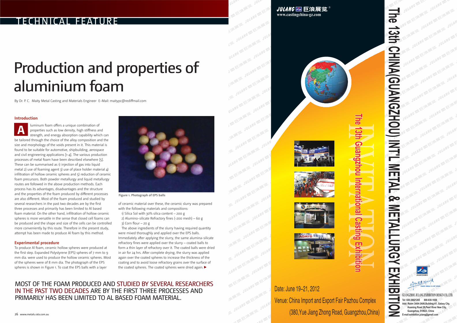
luminum foam offers a unique combination of properties such as low density, high stiffness and strength, and energy absorption capability which can
be tailored through the choice of the alloy composition and the size and morphology of the voids present in it. This material is found to be suitable for automotive, shipbuilding, aerospace and civil engineering applications [1-4]. The various production processes of metal foam have been described elsewhere [5]. These can be summarised as 1) injection of gas into liquid metal 2) use of foaming agent 3) use of place holder material 4) infiltration of hollow ceramic spheres and 5) reduction of ceramic foam precursors. Both powder metallurgy and liquid metallurgy routes are followed in the above production methods. Each process has its advantages, disadvantages and the structure and the properties of the foam produced by different processes are also different. Most of the foam produced and studied by several researchers in the past two decades are by the first three processes and primarily has been limited to Al based foam material. On the other hand, infiltration of hollow ceramic spheres is more versatile in the sense that closed cell foams can be produced and the shape and size of the cells can be controlled more conveniently by this route. Therefore in the present study, attempt has been made to produce Al foam by this method.
Experimental procedureTo produce Al foam, ceramic hollow spheres were produced at the first step. Expanded Polystyrene (EPS) spheres of 7 mm to 9 mm dia. were used to produce the hollow ceramic spheres. Most of the spheres were of 8 mm dia. The photograph of the EPS spheres is shown in Figure 1. To coat the EPS balls with a layer
of ceramic material over these, the ceramic slurry was prepared with the following materials and compositions:
1) Silica Sol with 30% silica content – 200 g2) Alumino-silicate Refractory fines (-200 mesh) – 60 g3) Corn flour – 20 gThe above ingredients of the slurry having required quantity
were mixed thoroughly and applied over the EPS balls. Immediately after applying the slurry, the same alumina-silicate refractory fines were applied over the slurry – coated balls to form a thin layer of refractory over it. The coated balls were dried in air for 24 hrs. After complete drying, the slurry was applied again over the coated spheres to increase the thickness of the coating and to avoid loose refractory grains over the surface of the coated spheres. The coated spheres were dried again.
Production and properties of aluminium foamBy Dr. P. C. Maity Metal Casting and Materials Engineer E-Mail: [email protected]
A
MOST OF THE FOAM PRODUCED AND STUDIED BY SEVERAL RESEARCHERS IN THE PAST TWO DECADES ARE BY THE FIRST THREE PROCESSES AND PRIMARILY HAS BEEN LIMITED TO AL BASED FOAM MATERIAL.
Figure 1. Photograph of EPS balls
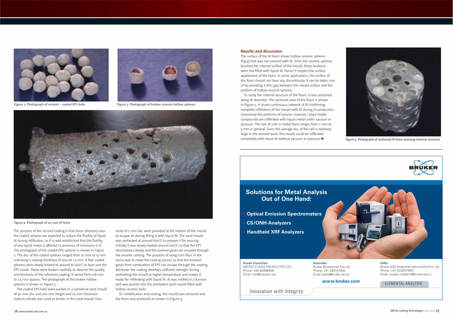
28 www.metals.rala.com.au METAL Casting Technologies June 2012 29
TECHNICAL FEATURE
The purpose of the second coating is that loose refractory over the coated spheres are expected to reduce the fluidity of liquid Al during infiltration, as it is well established that the fluidity of any liquid metal is affected in presence of inclusions in it. The photograph of the coated EPS spheres is shown in Figure 2. The dia. of the coated spheres ranged from 10 mm to 13 mm indicating a coating thickness of around 1.5 mm. A few coated spheres were slowly heated to around to 2000C to burn out the EPS inside. These were broken carefully to observe the quality and thickness of the refractory coating. It varied from 0.8 mm to 2.5 mm approx. The photograph of the broken hollow spheres is shown in Figure 3.
The coated EPS balls were packed in a cylindrical sand mould of 50 mm dia. and 200 mm height and 20 mm thickness. Sodium silicate was used as binder in the sand mould. Four
vents of 2 mm dia. were provided at the bottom of the mould to escape air during filling it with liquid Al. The sand mould was preheated at around 6000C to prepare it for pouring. Initially it was slowly heated around 2000C so that the EPS decomposes slowly and the evolved gases are escaped through the ceramic coating. The purpose of using corn flour in the slurry was to make the coating porous so that the evolved gases from combustion of EPS can escape through the coating. Moreover the coating develops sufficient strength during preheating the mould at higher temperature and makes it ready for infiltrating with liquid Al. Al was melted in a furnace and was poured into the preheated sand mould filled with hollow ceramic balls.
On solidification and cooling, the mould was removed and the foam was produced as shown in Figure 4.
Results and discussion The surface of the Al foam shows hollow ceramic spheres (Fig.4) that was not covered with Al. Since the ceramic spheres touched the internal surface of the mould, these locations were not filled with liquid Al. Hence it impairs the surface appearance of the foam. In some applications, the surface of the foam should not have any discontinuity. It can be taken care of by providing a thin gap between the mould surface and the preform of hollow ceramic spheres.
To study the internal structure of the foam, it was sectioned along its diameter. The sectional view of the foam is shown in Figure 5. It shows continuous network of Al confirming complete infiltration of the mould with Al during its production. Commonly the performs of ceramic material / place holder compounds are infiltrated with liquid metal under vacuum or pressure. The size of cells in metal foam ranges from 2 mm to 5 mm in general. Since the average dia. of the cell is relatively large in the present work, the mould could be infiltrated completely with liquid Al without vacuum or pressure.
Figure 2. Photograph of ceramic - coated EPS balls Figure 3. Photograph of broken ceramic hollow spheres
Figure 5. Photograph of sectioned Al foam showing internal structure
Figure 4. Photograph of as-cast Al foam
ELEMENTAL ANALYSIS
Innovation with Integrity
www.bruker.com
Optical Emission Spectrometers
CS/ONH-Analyzers
Handheld XRF Analyzers
Solutions for Metal AnalysisOut of One Hand:
Asean Countries MSITECH (ASIA PACIFIC) PTE LTDPhone: +65 65096938Email: [email protected]
Australia Bruker Biosciences Pty LtdPhone: +61 394747000Email: [email protected]
India Bruker AXS Analytical Instruments Pvt. Ltd Phone: +91 2232674001Email: [email protected]

30 www.metals.rala.com.au METAL Casting Technologies June 2012 31
TECHNICAL FEATURE
The successful infiltration depends upon the stability of the hollow ceramic spheres, as the whole structure of the preform can be damaged under liquid metals’ temperature and pressure. There can be filling of the hollow spheres with liquid metal, if part of the surface of the hollow spheres is damaged. In the present work, silica sol was used as the binder and alumina-silicate refractory grains were used as the filler, both are of high stability at high temperature. Moreover the thickness of the hollow spheres was sufficient to sustain the temperature and pressure of liquid Al. Hence the Al foam could be produced successfully.
As the ceramic spheres were randomly distributed inside the mould, some of the spheres were sectioned through its middle part, whereas others were sectioned near the edges. Hence the ceramic spheres of different orientation are observed over the sectioned surface. The thickness of the ceramic shell is also observed to vary (Figure 5) over the sectioned surface. Therefore the present method of coating needs to be improved to make a reasonably uniform thickness of the coating over the EPS balls.
The density of the foam was measured by weighing the cylindrical sample of the foam and by calculating the volume of the sample. The density of the solid Al is around 2.7 g/cc whereas the density of the foam was calculated as 1.79 g/cc, which is approx. 70% of the density of the solid Al. It has been reported that the density of various metal foams ranges from 20% to as low as 5% of the density of the respective solid metal. For example, Al foam of 0.38 g/cc to 0.76 g/cc was used in the experiments by Rajendran et al. [6]. Indeed the relative density of the metal foams depends primarily upon the method of its production. In most of the foams the preform or precursor materials are removed by dissolving in a solvent or by other techniques. The Al foam of the present work contains the ceramic spheres in it that could not be removed. The thickness of the hollow spheres is around 1.5 mm in average and the alumina-silicate refractory grain used in the work is of higher density than that of Al. Therefore the relative density of the Al foam is quite high.
Although the relative density of the Al foam is high, it can have other advantages. Most of the Al foam produced are envisaged for application in lightweight structural parts having energy absorption capability. Some of the potential uses of Al foam are in crashbox, rails, bumper, internal occupant protection in automobiles that require energy absorption capability [7]. This capability is reflected in the compressive stress – strain diagram of a foam material which shows a plateau region in stress over very large strain. It indicates the capability of the material to absorb energy over a constant force. The presence of ceramic material in the cells of the Al foam of present work can enhance its compressive strength. However since the ceramics are brittle in nature, the compressive behaviour of such foam composite needs to be studied in details to find its suitability for versatile applications.
ConclusionAl foam could be produced by liquid metal infiltration of ceramic hollow spheres. The density of the foam is high due to the presence of the ceramic material within the foam. The method is apparently applicable to high temperature alloys provided the ceramic hollow spheres are stable at the high temperature of the alloy used. ■
REFERENCES
1) T. Mukai, H. Kanahashi, T. Miyoshi, M. Mabuchi, T.G. Nieh and K. Higashi, Scripta Mater., 40 (1999), pp.921-927.
2) K. Y. G. McCulough, N. A. Fleck and M. F. Ashby, Acta Mater. 47 (1999), pp.2323-2330.
3) F. Yi, Z. Zhu, F. Zu, S. Hu and P. Yi, Mater. Characterization, 47 (2001) pp.417-422.
4) K. Kitazano, E. Sato and K. Kuribayashi, Scripta Mater. 50 (2004) pp. 495-498.
5) P. C. Maity, Metal Casting Technologies, Vol.55, N0.3, September 2009, pp.55-57.
6) R. Rajendran, K. Prem Sai, B. Chandrasekar, A. Gokhale and S. Basu, Materials and Design 29 (2008) pp. 1732-1739.
7) www.cymat.com
SOME OF THE POTENTIAL USES OF AL FOAM ARE IN CRASHBOX, RAILS, BUMPER, INTERNAL OCCUPANT PROTECTION IN AUTOMOBILES THAT REQUIRE ENERGY ABSORPTION CAPABILITY
WEBSITE SHOWCASE
www.afi australia.org/nsw www.beckwithmacbro.com.au www.bruker-elemental.com www.cast.org.au
www.foseco.com.au www.gcinstrument.com.au www.imf.it www.inductotherm.com.au
www.linn.de www.magmasoft.com.sg www.pacrim.com.au www.sibelco.com
www.spectro.com/lab www.synchroerp.com www.thermoscientifi c.com/oes www.warill.com.au

32 www.metals.rala.com.au METAL Casting Technologies June 2012 33
n this article Nev Murray, an Australian veteran foundryman, takes a look back at the history of patternmakers. It is sometimes worthwhile refreshing
the basics of what we are in business.
Ancient beginnings - productivity, quality and deliveryPatternmakers suddenly became important when the ancient metal caster, working from his cave, received an order, not for the usual one off, but for a batch of castings to be all the same shape, size and wanted urgently. Until then, the casting shape was roughly chiselled out of a piece of stone, and molten metal was poured in to make the cast shape. For the new order the metal caster had to engage the expertise of a specialist called a ‘patternmaker’. The metal caster needed a ‘model’ carved out of wood, the same shape his customer wanted as a casting, so that he could make multiple clay moulds to cast metal into. This job required the expertise of a specialist with skills he didn’t have. A patternmaker was needed.
The patternmaker made it possible, resulting in higher production, better quality, delivered on time and more money. The patternmaker alone had turned the ancient metal caster into what we now call the foundry industry. The metal caster became a ‘foundry manager’ and the rest is history.
The fi rst industrial revolution BC – CastingsBefore long castings were being made all over the known world in various metas and quality.
First trinket castings for jewellery, then agricultural implements to dig the ground for crops, then more destructive weapons to
wage war on the neighbours. The first industrial revolution, on this planet, had arrived.
Everybody wanted castings, good, cheap and fast. Patternmakers were in demand.
History - wealth and expansionHistory does not record when the term ‘patternmaker’ was first actually used to define the function of what we accept as the basic starting point of the foundry industry. After the first production pattern was made and identical multiple moulds could be used, the moulder was created. Following this innovation there was an ‘urge’ to produce more metal and the metallurgist was created. Obviously the industry was then counting more money and the accountant was created. The modern business structure was cast.
What is a foundry patternmaker?The critical importance of the foundry patternmakerIn this article Nev Murray, an Australian veteran foundryman, takes a look back at the history of patternmakers. It is sometimes worthwhile refreshing the basics of what we are in business.
I
Dictionary - Pattern. ‘A formed shape usually wooden imbedded into a sand or clay mould for metal casting’.The foundry patternmaker is a tradesman trained artisan skilled in the craft of reading an engineering drawing to make an accurate
model (pattern), using hand tools and machinery, to be used in foundry making sand moulds for the production of metal castings.
Casting metal into stone moulds before the patternmaker arrived
Innovation – bigger is betterThe basic principles of a foundry had been established for production of castings, and there wasn’t any significant technological improvements for quite a long time, but patternmakers found they had to be innovative and creative to help the foundry industry expand to meet the demand for more, bigger, better and cheaper castings.
Constant up-skilling of the patternmaker became necessary to make patterns suitable for changes to modern high pressure high volume moulding and core machines. Machinery has replaced the moulder but cannot replace the patternmaker. The patternmaker is unique in the ability to absorb skills necessary to provide the service to foundries constantly introducing new production technologies.
The patternmaker from ancient ChinaWe need to go right back to when metal was first melted and cast into moulds for a finished product.
Possibly the explanation why the ‘specialist’ was called a patternmaker is evidenced by the fact that in ancient China elaborately patterned metal castings were well established before ‘the rest of the world’ got into it’. In fact iron casting in China 402 - 221 BC pre-dated the Bronze Age in Europe. This fact could be attributed to the Chinese archaeological artefacts of Shang Dynasty 1523 - 1027 BC with many elegant cast articles with identical elaborate pattern designs moulded into the outer faces. Weapons of war also benefited from the ability to mass produce metal castings of identical shape. During the Ch’in dynasty around 200BC, hundreds and probably thousands of fine accurately cast to size metal cross bow trigger mechanisms were made, which were interchangeable. The mechanism consisted of five intricately shaped castings which fitted together unmachined. This devastating and effective weapon would not be seen in the west for another 600 years. An elaborate design is difficult to accurately reproduce by individually carving it out of clay, and it’s slow and expensive. A single wood pattern could make many clay moulds very quickly.
Western origins from 1300ADWooden patterns were employed by members of the Worshipful Company of Founders Guild in England whose guild existed in London in the 1300’s and to The master moulders in the 1500’s as cannon founders to King Henry VII and VIII. Cannon production was big business.
The first permanent foundry tooling (patterns) was for cannon, pots and stoves in Flanders and the western parts of what is now Germany.
Permanent wood patterns became prevalent during the
Industrial Revolution circa 1760, which provided the tool that permitted faithful reproduction of complicated metal shapes at a reasonable price.
The ‘Worshipful Company of Founders Guild’Patternmaking in America has lineage back to the English ‘Worshipful Company of Founders Guild’, whose motto was ‘GOD THE ONLY FOUNDER’.
Patternmakers are first recorded at the first foundry in America at Saugus, Massachusetts Bay Colony (1642 – 1675) evidenced by surviving mass
produced three-legged pots.
Patternmaking as a Trade – modern originsHistorically, unlike other crafts, very few books have been written specifically about foundry patternmaking and very little authoritative attempts have been made to formally standardise or produce guides of direction by governments or manufacturing industry societies/associations about pattern design or
Members Plaque Worshipful Company of
Founders Guild London 1300’s.
FEATURE
Belec Lab 3000s Spectrometerfor accurate Cast Iron and Steel Analysis
G & C Instrument Services P/LWebsite: www.gcinstrument.com.au
Email: [email protected] Telephone: +61 (0)2 4981 7255
✓Easily Installed!
✓Low Running Costs!
✓ No Special Power Requirements!
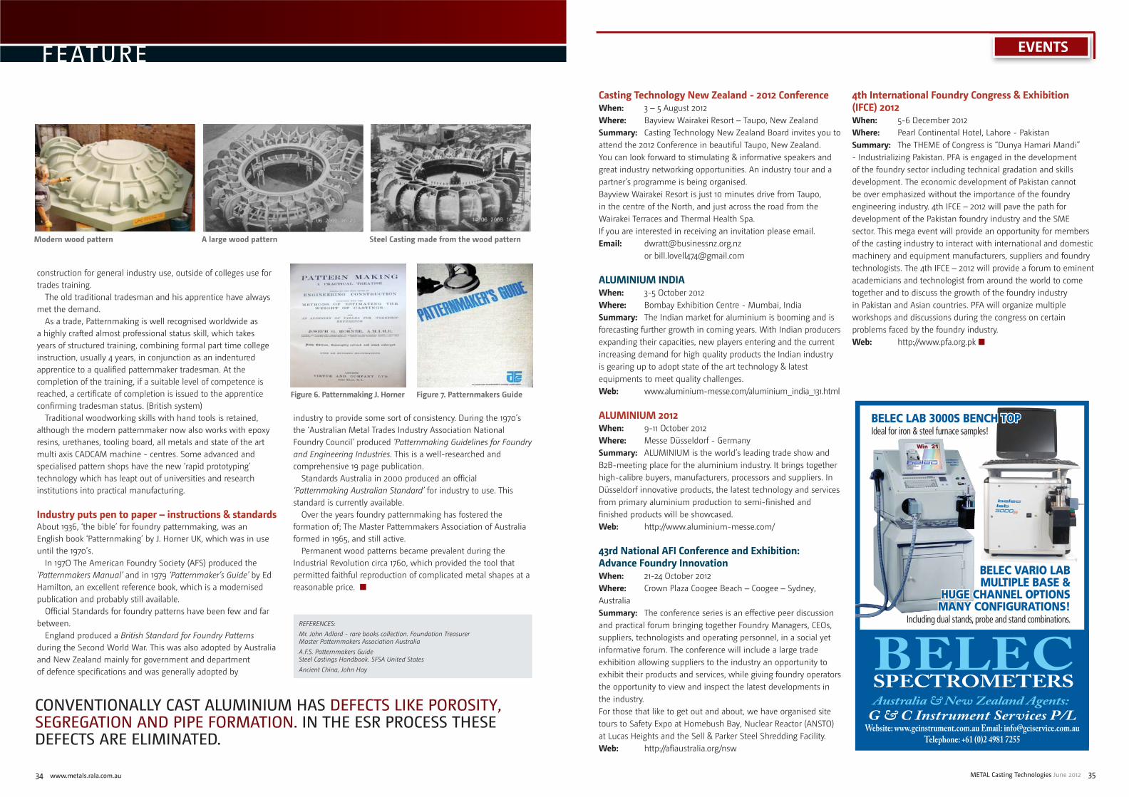
34 www.metals.rala.com.au METAL Casting Technologies June 2012 35
EVENTS
Casting Technology New Zealand - 2012 ConferenceWhen: 3 – 5 August 2012Where: Bayview Wairakei Resort – Taupo, New ZealandSummary: Casting Technology New Zealand Board invites you to attend the 2012 Conference in beautiful Taupo, New Zealand. You can look forward to stimulating & informative speakers and great industry networking opportunities. An industry tour and a partner’s programme is being organised.Bayview Wairakei Resort is just 10 minutes drive from Taupo, in the centre of the North, and just across the road from the Wairakei Terraces and Thermal Health Spa.If you are interested in receiving an invitation please email.Email: [email protected] or [email protected]
ALUMINIUM INDIAWhen: 3-5 October 2012Where: Bombay Exhibition Centre - Mumbai, IndiaSummary: The Indian market for aluminium is booming and is forecasting further growth in coming years. With Indian producers expanding their capacities, new players entering and the current increasing demand for high quality products the Indian industry is gearing up to adopt state of the art technology & latest equipments to meet quality challenges.Web: www.aluminium-messe.com/aluminium_india_131.html
ALUMINIUM 2012When: 9-11 October 2012Where: Messe Düsseldorf - GermanySummary: ALUMINIUM is the world’s leading trade show and B2B-meeting place for the aluminium industry. It brings together high-calibre buyers, manufacturers, processors and suppliers. In Düsseldorf innovative products, the latest technology and services from primary aluminium production to semi-finished and finished products will be showcased.Web: http://www.aluminium-messe.com/
43rd National AFI Conference and Exhibition: Advance Foundry InnovationWhen: 21-24 October 2012Where: Crown Plaza Coogee Beach – Coogee – Sydney, AustraliaSummary: The conference series is an effective peer discussion and practical forum bringing together Foundry Managers, CEOs, suppliers, technologists and operating personnel, in a social yet informative forum. The conference will include a large trade exhibition allowing suppliers to the industry an opportunity to exhibit their products and services, while giving foundry operators the opportunity to view and inspect the latest developments in the industry.For those that like to get out and about, we have organised site tours to Safety Expo at Homebush Bay, Nuclear Reactor (ANSTO) at Lucas Heights and the Sell & Parker Steel Shredding Facility.Web: http://afiaustralia.org/nsw
4th International Foundry Congress & Exhibition (IFCE) 2012When: 5-6 December 2012Where: Pearl Continental Hotel, Lahore - Pakistan Summary: The THEME of Congress is “Dunya Hamari Mandi” - Industrializing Pakistan. PFA is engaged in the development of the foundry sector including technical gradation and skills development. The economic development of Pakistan cannot be over emphasized without the importance of the foundry engineering industry. 4th IFCE – 2012 will pave the path for development of the Pakistan foundry industry and the SME sector. This mega event will provide an opportunity for members of the casting industry to interact with international and domestic machinery and equipment manufacturers, suppliers and foundry technologists. The 4th IFCE – 2012 will provide a forum to eminent academicians and technologist from around the world to come together and to discuss the growth of the foundry industry in Pakistan and Asian countries. PFA will organize multiple workshops and discussions during the congress on certain problems faced by the foundry industry.Web: http://www.pfa.org.pk ■
CONVENTIONALLY CAST ALUMINIUM HAS DEFECTS LIKE POROSITY, SEGREGATION AND PIPE FORMATION. IN THE ESR PROCESS THESE DEFECTS ARE ELIMINATED.
construction for general industry use, outside of colleges use for trades training.
The old traditional tradesman and his apprentice have always met the demand.
As a trade, Patternmaking is well recognised worldwide as a highly crafted almost professional status skill, which takes years of structured training, combining formal part time college instruction, usually 4 years, in conjunction as an indentured apprentice to a qualified patternmaker tradesman. At the completion of the training, if a suitable level of competence is reached, a certificate of completion is issued to the apprentice confirming tradesman status. (British system)
Traditional woodworking skills with hand tools is retained, although the modern patternmaker now also works with epoxy resins, urethanes, tooling board, all metals and state of the art multi axis CADCAM machine - centres. Some advanced and specialised pattern shops have the new ‘rapid prototyping’ technology which has leapt out of universities and research institutions into practical manufacturing.
Industry puts pen to paper – instructions & standardsAbout 1936, ‘the bible’ for foundry patternmaking, was an English book ‘Patternmaking’ by J. Horner UK, which was in use until the 1970’s.
In 197O The American Foundry Society (AFS) produced the ‘Patternmakers Manual’ and in 1979 ‘Patternmaker’s Guide’ by Ed Hamilton, an excellent reference book, which is a modernised publication and probably still available.
Official Standards for foundry patterns have been few and far between.
England produced a British Standard for Foundry Patterns during the Second World War. This was also adopted by Australia and New Zealand mainly for government and department of defence specifications and was generally adopted by
industry to provide some sort of consistency. During the 1970’s the ‘Australian Metal Trades Industry Association National Foundry Council’ produced ‘Patternmaking Guidelines for Foundry and Engineering Industries. This is a well-researched and comprehensive 19 page publication.
Standards Australia in 2000 produced an official ‘Patternmaking Australian Standard’ for industry to use. This standard is currently available.
Over the years foundry patternmaking has fostered the formation of; The Master Patternmakers Association of Australia formed in 1965, and still active.
Permanent wood patterns became prevalent during the Industrial Revolution circa 1760, which provided the tool that permitted faithful reproduction of complicated metal shapes at a reasonable price. ■
Modern wood pattern A large wood pattern Steel Casting made from the wood pattern
Figure 6. Patternmaking J. Horner Figure 7. Patternmakers Guide
REFERENCES:Mr. John Adlard - rare books collection. Foundation TreasurerMaster Patternmakers Association AustraliaA.F.S. Patternmakers GuideSteel Castings Handbook. SFSA United StatesAncient China, John Hay
FEATURE
G & C Instrument Services P/LWebsite: www.gcinstrument.com.au Email: [email protected]
Telephone: +61 (0)2 4981 7255
BELEC SPECTROMETERSAustralia & New Zealand Agents:
BELEC LAB 3000S BENCH TOPBELEC LAB 3000S BENCH TOPIdeal for iron & steel furnace samples!
BELEC VARIO LAB BELEC VARIO LAB MULTIPLE BASE & MULTIPLE BASE &
HUGE CHANNEL OPTIONSHUGE CHANNEL OPTIONSMANY CONFIGURATIONS! MANY CONFIGURATIONS!
Including dual stands, probe and stand combinations.

36 www.metals.rala.com.au METAL Casting Technologies June 2012 37
Back to B A S I C S
Introductionluminium-silicon alloys are widely used in the casting industry due to their excellent castability and good mechanical properties. The alloys consist predominantly
of aluminium with silicon addition up to 11% (hypoeutectic), 11 to 13% (eutectic) and over 13% (hypereutectic) with various other elements such as magnesium, zinc, iron, copper and nickel added to achieve desired casting and mechanical properties. Silicon is the most significant alloying ingredient and is primarily responsible for the excellent castability of these alloys. Silicon increases fluidity, wear resistance and strength, whilst it reduces melting temperature, solidification contraction and hot-tears.
Aluminium-silicon casting alloys are essential to a wide range of industries including engineering, aeronautical and automotive and are suitable for sand or die casting processes.
Al-Si is a simple eutectic system of two solid solution phases where each element has little or no solubility in the other.
Aluminium melts at approximately 660oC while silicon melts at 1414oC. The diagram in figure 2 shows the eutectic at 12.6 wt % Si and 577oC. The maximum solubility of Si in Al is approximately 1.65% at 577oC.
Generally with binary alloys when there are approximately equal volume fractions of the two phases, eutectics of these alloys exhibit a lamellar structure. If, however, one phase is present in a small volume fraction, this phase tends to be fibrous. In the case of Aluminium-silicon alloys, the silicon tends to form coarse and brittle needle-like particles which are detrimental to the strength of the casting. See figure 3.
Modifi cationModification describes a condition of refinement of the acicular silicon crystal in the aluminium-silicon eutectic. This structural modification of the silicon crystal is achieved by the addition of elements such as sodium and strontium to hypoeutectic alloys.
These modifying additions suppress the growth of the silicon crystal within the eutectic thus producing a finer distribution as such as shown in figure 4.
The higher the silicon level in the alloy, the greater the amount of modifying element required to achieve structural modification. Likewise, the lower the cooling rate in the casting the greater the required addition.
The first structural modifiers of hypoeutectic aluminium-silicon alloys were based on sodium. Sodium has a strong undercooling effect so that it is particularly useful when cooling rates are low such as with sand casting. Sodium is very reactive and is generally introduced into the liquid alloy in the form of salts which are “rabbled” into the surface, or as metallic sodium which is packed in vacuum sealed containers. In both cases, care must be taken to prevent accidents, metallic sodium containers must be held under the surface of the liquid metal until all reaction has ceased. Problems associated with the use of sodium modifiers included objectionable fumes and high rates of fade. Sodium additions are typically in the range of 0.005 to 0.02%. Higher additions should be avoided as they can result in over-modification which causes a reduction in mechanical properties. Accurate control of sodium level can be difficult due to its high reactivity.
Strontium is added as a master alloy for use in hypoeutectic and eutectic aluminium-silicon alloys. Strontium modification offer advantages such as low fume, better recovery and reduced fade compared to sodium-based modifiers. The reduced rate of fade makes this method of modification particularly well suited to diecasting applications where it may be necessary to hold molten metal for long periods of time. The amount of strontium modifier to add depends not only on the degree of modification required, but is also influenced by such factors as the silicon content of the alloy, the cooling rate of the casting, the holding time and metal temperature. Generally, additions of 0.02 to 0.04% are adequate for most applications.
Small additions of antimony can be used to obtain permanent modification of the eutectic phase in aluminium-silicon alloys. Antimony is largely unaffected by holding time, degassing or remelting. Antimony is not compatible with sodium and strontium and the modifying properties of these elements can be seriously impaired if cross-contamination occurs. It is not usual to use antimony in foundry applications due to the toxic nature of the material and the risk of over-modification when returns are recycled.
The mechanism of refining the primary silicon structure is different for hypereutectic aluminium-silicon alloys. These alloys are frequently used for wear resistant applications where it is necessary for the primary silicon to be evenly dispersed throughout the casting. With slow cooling rates and long freezing ranges, growth and floatation of primary silicon can occur. Large silicon particles are detrimental to castability, machinability, mechanical and wear properties. Hypereutectic alloys can be refined by the addition of small amounts of phosphorous. Phosphorous combines with aluminium in the melt to form tiny insoluble aluminium-phosphide particles that act as nuclei on which primary silicon crystal can grow ensuring a fine dispersion of silicon in the eutectic matrix.
Benefi ts of modifi cationStructural modification of aluminium-silicon alloys has a number of beneficial effects, which include:
• Improved mechanical properties• Improved machinability• Improved wear properties• Reduced hot-tearing• Increased pressure tightness• Reduced shrinkage porosity• Increased response to heat treatment• Improved die filling
AcknowledgmentThe photomicrographs appearing as Figures 3 and 4 are from George Vander Voort presentation “The Aluminium-Silicon Phase Diagram and Eutectic Modifications” ■
Modification of aluminium-silicon foundry alloysJ. F. Meredith, Casting Solutions Pty Ltd
Figure 1. Aluminium-silicon alloy castings.
Figure 3. Needles of coarse silicon in unmodified Al, 12% Si alloy.
Figure 2. Al-Si phase diagram.
Figure 4. Sodium modified Al, 12% Si allo
A
REFERENCES
1. Aluminium Casting Technology 2nd Edition – American Foundrymen’s Society Inc 1993
2. Modiification of Aluminium-Silicon Foundry Alloys – Dr R Cook, Metallurg Aluminium – London & Scandinavian Metallurgical Co Limited 1998
3. Foseco Non-Ferrous Foundryman’s Handbook Eleventh Edition – Butterworth Heinemann 1999
www.linn.de
Production line for γ-TiAl consisting of mould pre heating rotary hearthfurnace, conveyor furnace for annealing of castings under protective gas and centrifugal casting unit.
Turbine blades, turbocharger wheels. γ-TiAl, Ti, Ni-basis, Al, Mg.
Induction heated precision centrifugal fine casting systems up to 2 kg Ti /TiAl, 3 kg Steel, 1 kg Al/Mg, e.g.
Rotary hearth furnace forpre heating of ceramic casting moulds for TiAl, Ti, Pt, Ni-basis. Up to 1100 °C. 3 turn tables (Ø 940 mm).

38 www.metals.rala.com.au METAL Casting Technologies June 2012 39
Back to the
onsideration is given to fuel first and furnaces second because the nature of the fuel that is available is the controlling factor in deciding the type of furnace to be
used. Where natural gas is available, it may be more economical to use rather than electricity. However, careful consideration should be given as to whether a natural gas furnace system will give a product that will meet the standard of quality specified for the castings to be made, and whether the working conditions in the foundry will be acceptable. Taking all other things equal, the slogan to be clearly followed in any foundry is:
The foundry is a pleasant place to work inThis means the foundry should have maximum light, both natural and artificial, be as cool as possible during summer and comfortably warm in winter, and as free as possible from dust and noise and unduly concentrated heat in any area. Keeping the slogan in mind, let us take a trip down memory lane and see what major types of furnaces were used for the melting bronze in the past.
Pit-type coke-fi red crucible furnacesThere was the pit-type furnace where the crucible was placed and surrounded by burning coke using natural draft. Mechanical thongs on hoists were used to carry the loaded crucible in or out of the furnace. As the metal becomes melted, it is adjusted in composition, covered, and worked up to pouring temperature. Using the mechanical thongs, the hot crucible was then hoisted out and usually used as the pouring crucible, too. There could be as many crucibles as there are melt compositions to be made to avoid contamination of the melt. Very good bronze was produced in this type of furnace. One difficulty with this system, besides the heat and difficulty encountered by the melters who had to straddle close to the open hole of the pit furnace to retrieve the crucible full of hot melt, is the control of the effluent smoke and gases generated and the subsequent cleaning and maintenance of the pit. This was the type of furnace that I encountered when I “accidentally” got involved in the foundry industry as a young engineer years ago.
Reference has been made to the arduous nature of the work in connection with the removal of the crucibles from the furnace. Undoubtedly, this should be done by mechanical means. The days are over for the lifting of the crucible by two men who, having placed the crucible thongs around the crucible (itself a heat exposing job, although unavoidable then), proceed to straddle the
furnace while lifting the crucible up to and onto the foundry floor, their leggings scorching with the heat.
The natural draft pit-type furnace is greatly affected by the weather, the draft being poor on windless humid days and better on dry windy days. This draft could be supplemented; however, with air from an air-compressor as forced draft. The main objection to coke as a fuel is the fact that it can happen that the molten metal in the crucible, not having reached the required temperature by the time the fuel around the crucible has burned away, cannot be brought up to the required temperature until the fuel is renewed. This means a delay of from one to one-and-a-half hours. Another objection is the labor needed to coke the fires and clean out the ashes, not to mention the possible contamination of the melt by pieces of the solid fuel.
Care of cruciblesThe use of crucibles brings up the question of their care. As received, the crucible, made of silicon carbide, has absorbed a considerable amount of moisture and the nature of the material is such that it requires a steady and continuous heat to dry it out. Further, the material is capable of re-absorbing moisture after once being dried. With these facts in mind, the crucibles should have a proper place kept for them, in the general nature of a core oven, with suitable shelves. The oven should be maintained at a temperature between 135-163˚C (275-325˚F). Care in handling at all times should be the watchword. The life of the crucibles is directly proportional to the care they receive. At the end of the day, the crucibles in use should be put in the crucible oven after they have cooled a little. Another thing to remember is that a red hot crucible is much more delicate than a cold one. Every care should therefore be taken in handling them during their removal from the furnace. The crucible thongs and shanks should be made to fit well the contour of each kind of crucible and undue squeezing should be avoided. They should, at all times, be kept from contact with such moisture as damp sand on the foundry floor or otherwise.
Fixed pouring oil-fi red, crucible furnacesThen there was the oil-fired, crucible furnace of the fixed pouring type. Here the crucible is larger and the whole furnace tilts to facilitate the pouring operation. Natural gas or diesel oil is used as fuel introduced through a burner at the bottom of the crucible in the furnace at an angle tangent to the circumference of the crucible
making the effluent gases and smoke go around the crucible and exit through the hole at the center of the furnace cover. This makes it much easier to maintain an oxidizing flame (slightly yellowish) and avoid a reducing flame (slightly greenish) to avoid the entry of hydrogen in the melt, which is difficult to remove from the melt, and which causes gas holes in the casting. It would be preferable to allow some oxygen to get into the melt to react with the hydrogen and come out of the top hole in the cover as water vapor. It is then an easy matter to remove the excess oxygen in the melt by using a deoxidizer during the tapping of the melt. One difficulty with this system is, if you have only one furnace, you face the danger of contamination of succeeding melts since you have only one melting crucible. There would then be required as many furnaces as there are compositions to be melted. This is the type of furnace I designed and built for our foundry after gaining enough experience (I remember making three furnaces of this type, as I gained more knowledge in foundry operations, since these three were sufficient to avoid or control contamination of the melt of the alloys we produced).
Electric furnacesNow we come to electric furnaces. The indirect-arc, revolving type of furnace is very suitable for most foundry melting. The resistor-type is another type. The former is a noise-maker due to the arc; but the latter is nearly noiseless. Both of these operate with relatively cleaner atmospheres as compared with oil-fired furnaces. As in all built-in furnaces, the facility for changing from one alloy to another several times a day is lost as only one furnace hearth is used for all alloys and contamination definitely cannot be avoided. These furnaces are indicated for the large production of one type of alloy. The high-frequency, induction furnace of the lift-coil type is the preferable furnace for the melting of many types of alloy in one day. This is the best type of furnace for a jobbing bronze foundry producing several alloys per day.
High-frequency, electric induction, lift-coil furnacesFinally, there is the high-frequency electric induction furnace of the lift-coil type. This is ideal for making melt-after-melt-after-melt throughout the whole day. There is only one induction coil that could be placed on either one of two crucibles. There could be as many crucibles as there are melt-compositions made. First one crucible is charged and the induction coil placed over and around it. Melting could then proceed. The outside of the crucible may be scarcely visibly red while the metal inside is at 1200˚C (2200˚F). With this type of furnace, the mixing is automatic caused by the
eddy currents generated by the induction coil. The temperature obtainable is only limited by the fusing point of the crucible; there is no noise, and the surrounding temperature in the vicinity of the melting is almost the same as if no furnace was there. The melting time is extremely short and, when electric power is reasonable, so is the cost. Meanwhile, the other crucible on the same platform-on-wheels could be charged and made ready for melting. When the first crucible is done, the induction coil is lifted up and placed over the second crucible to commence melting in this one. The first crucible could then be used to pour the relevant molds. While pouring is going on, even a third crucible could be charging and preparing for melting, as necessary. The process could be repeated on and on continuously throughout the day. There are not much effluent gases to be of any problem, as this is a clean-melting system. The only real problem here is the availability and the cost of electric power, if available. The main objection to this type of furnace is the capital outlay, but the improvement in working conditions, the uniformity of the metal produced, the quality of the castings made, and the flexibility of the operation do justify the outlay, if other requirements make it suitable.
RecapitulationThe choice of a melting unit actually depends on the kind of operation planned for the foundry. When the castings to be made weigh only, on the average, no more than 100 kgs. each (220 lbs.) and where it may be necessary to make many types of alloys – or even make nickel or other high melting point alloys – and where ideal working conditions around the furnaces are considered important with particular attention to the absence of heat and noise, then the high-frequency induction lift-coil type of crucible furnace is to be preferred. For practical purposes, it would be better to have one crucible for each type of the following alloys to avoid contamination of the melt: (1) tin bronzes, (2) leaded tin bronzes, leaded brasses, and phosphor bronzes, (3) manganese bronzes – actually a brass – and standard brasses, (4) aluminum bronzes, (5) nickel bronzes, (6) silicon bronzes, and (7) beryllium bronzes. In this type of furnace, no ladles or ladle heaters are required, and no mechanical mixing is needed.
However, where larger amounts of metal are needed, for castings heavier than the above, than the lift-coil furnace can provide, almost the same form and system of melting is available in the oil-fired, fixed-pouring crucible furnaces, as an alternative. As an added advantage here, this type of oil-fired furnace can be fabricated in-house easily – except for the crucible and the burner – and the foundry can have as many furnaces as the type of
Furnaces for the virtual bronze foundry
CBy Prof. John H. D. Bautista, PEE, RMetE, MBA; Technical Consultant, Phil. Metalcasting Association., Inc.
THE HIGH-FREQUENCY, INDUCTION FURNACE OF THE LIFT-COIL TYPE IS THE PREFERABLE FURNACE FOR THE MELTING OF MANY TYPES OF ALLOY IN ONE DAY.

40 www.metals.rala.com.au
Back to the
alloys desired to be produced to avoid melt contamination, that is, one furnace per type of alloy to be produced.
In fabricating oil-fired furnaces the following should be observed:
The size of the crucible will depend on the melting plan and the volume of melt to be made per heat and the crucible should be with a spout.
The furnace shall be built around the crucible with a refractory lining of about 10 cms. (4-inches) thick all around, including cover and bottom, and the clearance between the crucible and the lining shall be about 5 cms. (2-inches) at the lip of the crucible. This is regardless of the size of the crucible. The furnace cover shall have a 10-cm. (4-inch) hole at the center and shall be about 5-cms. (2-inches) clearance over the crucible lip. The crucible shall sit on a “pedestal” about 10 cms. (4-inches) thick and a tap hole shall be provided to tap out any molten metal in case of a crucible breakage during melting. The furnace cover should be able to lift about an inch and swayed to one side to facilitate charging.
The burner shall be directed horizontally and tangentially at the
bottom of the crucible. If you are in the northern hemisphere – north of the equator – the flame should go around the crucible in a counterclockwise manner; and conversely, if you are in the southern hemisphere – south of the equator – the flame should go clockwise. This is to avoid any turbulence in the flame.
The furnace should sit on a rack where a system of worm and worm-wheel gear system could be used to tilt the furnace as necessary. The furnace could be held in any position towards tilting.
It is preferable to use composition ingots rather than virgin metal or assorted scrap.
A guide for furnace dimensional specifications is given here to help in-plant fabrication. It should be noted that the furnace doesn’t have to be really complicated; otherwise, buy a commercial furnace. ■
REFERENCES(a) Harold J. Roast, Cast Bronze, The American Society for Metals.
Style Cru. Size
Cap. A B C D E F G H I J K L M N O
180 G.T. 40 120 14 3/8 197/8 283/8 231/8 383/8 14 7/8 14 3/8 287/8 543/4 403/8 6711/14 38 3/4 333/4 141/2 14 7/16
180 G.T. 5060
150180 16 21 3/4 30 25 401/4 14 7/8 139/16 287/8 563/4 403/8 691/4 403/8 333/4 141/2 14 7/16
800 G.T.70 210 163/8 225/8 303/8 26 41 1/4 14 7/8 13 7/16 287/8 573/4 403/8 6911/16 403/4 333/4 141/2 14 7/16
800 G.T. 8090
240270 175/8 243/4 315/8 28 431/4 14 7/8 123/4 287/8 595/8 403/8 71 42 333/4 141/2 14 7/16
Capacities in pounds and dimensions in inches
Dimensional Specifications for a single burner, oil-fired, tilting crucible furnace
Here is a guide to help in the in-plant fabrication of an oil-fired, tilting crucible furnace for melting bronze (it could be less complicated).
ARL 4460 Optical Emission Spectrometer Outstanding performance for elemental and inclusion analysis in steel
ARL PERFORM’X Advanced WDXRF Spectrometer X-ray elemental analysis where performance meets versatility
ARL 9900 XRF Series with Integrated XRD Capability Capable, fast X-ray system that combines XRF and XRD
Niton XL2 XRF Analyzer Fast, accurate alloy analysis and grade identification. Anytime, anywhere
Quality analysis is essential to your products, productivity and profitability.
We offer solutions that fit your needs and your budget. From iron ores to
steel and inclusions, our instruments deliver unmatched speed, precision
and accuracy. Versatile,non-destructive XRF and XRD. Industry-leading
OES. Highly efficient automated instruments including sample preparation.
A network of local support. You’ll have the instruments and expertise to
achieve superior product quality, reduce costs and maximize uptime.
that specs and budgets will be met
You areassured
www.thermoscientific.com/assured
© 2
010
Ther
mo
Fish
er S
cien
tific
Inc.
All
right
s re
serv
ed.
COATINGS
FILTRATION
FEEDING SYSTEMS
MELT SHOP REFRACTORIES
METAL TREATMENT
BINDERS
CRUCIBLES
C O M M I T T E D T O F O U N D R I E S
The world is full of great double acts. Our technology and your foundry, for instance, to make premium-grade casting products. Or your castings in the hands of engineers who produce great technology that serves us every day.
Our locally based teams of foundry specialists are on hand to help you develop innovative solutions to suit your mould and core binder needs.
Our products, services and expertise coupled with your skills and process knowledge can unlock the full potential of your foundry operations.
As a reliable and trusted supplier, Foseco can help you to improve casting strength and nish, reduce fume emissions during coremaking and moulding, raise reclamation rates or perhaps boost productivity.
Whatever your foundry requirements are, talk to us.
Your foundry and Foseco. The power of two.
THE POWER OF 2
Phone: + (61) 2 9914 5500 Fax: + (61) 2 9914 5547www.foseco.com.au
POLITEC* | NORACEL* | ECOLOTEC* | FUROTEC* | FENOTEC* | POLISET*
* POLITEC, NORACEL, ECOLOTEC, FUROTEC; FENOTEC and POLISET are trade marks of the Vesuvius Group, registered in certain countries, used under licence.